
Ask AI
— answers from the official manualAnswers from the official manual.
Common questions
Common Questions
9 totalHow do I set up the maximum speed limit on my KT-LCD3?
To set up the maximum speed limit, start by turning on the meter and within five seconds simultaneously hold the UP and Down buttons for three seconds. Use the DOWN button to decrease or UP button to increase the desired speed limit.
What are the steps to change wheel diameter settings?
To adjust the wheel diameter setting, during general project setup use the DOWN button to cycle through menu options until 'DST' is flashing. Choose from available diameters (e.g., inches or cm) by pressing UP and Down buttons.
How can I set the motor characteristic parameters on my KT-LCD3?
To configure motor characteristics, enter P Parameter settings after cycling through general options. Use UP and DOWN buttons to select values within a range of 0-255 for P1 (Motor Gear Reduction Ratio * Rotor Magnets).
How do I enable cruise control function?
To activate the Cruise Function, set C7 parameter to 'Enabled' in the C Parameter Settings menu. Once enabled and vehicle is moving above 7Km/H hold the DOWN button for three seconds.
How do I reset my KT-LCD3 if I forget or lost the startup password?
To restore default settings in case of forgotten passwords, set C10 value to ‘Enabled’, then hold Power button for two seconds. It’s recommended to back up parameters before resetting.
What is the process to display motor temperature?
To enable motor operating temperature display, set C8 parameter value to 'Enabled' in the C Parameter settings menu from the previous configuration steps.
Full Manual
31 pages

KT-LCD3
User Manual eBike Special Meter

Please read through carefully before use
English
PREFACE
This manual aims to help the user understand and familiarise themselves with the meter function, operation of the meter, how to set the project parameters, how to achieve the best match of the three (motor, controller, and meter) to improve electronic control performance of the electric motor. This manual covers installation, operation, parameter setting of the meter and how to use it properly, which help user resolve issues that arise from use.
OUTLOOK AND SIZE
Meter Dimension

Meter Dimension

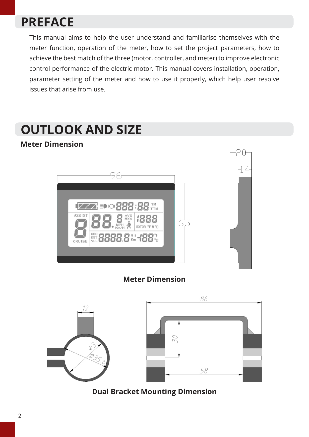
Dual Bracket Mounting Dimension
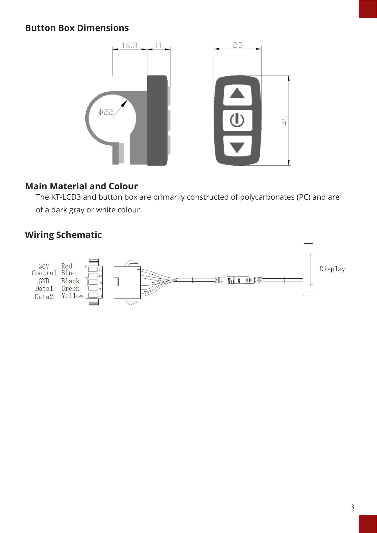
##### Button Box Dimensions

##### Main Material and Colour
The KT-LCD3 and button box are primarily constructed of polycarbonates (PC) and are of a dark gray or white colour.
##### Wiring Schematic

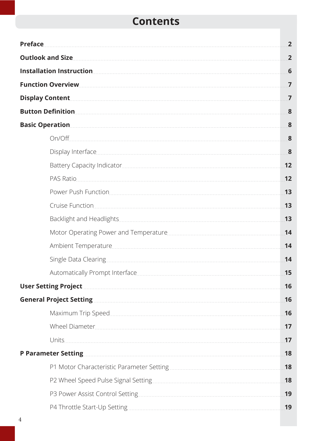
#### Contents
Preface 2 Outlook and Size 2 Installation Instruction 6 Function Overview 7 Display Content 7 Button Definition 8 Basic Operation 8
On/Off 8 Display Interface 8 Battery Capacity Indicator 12 PAS Ratio 12 Power Push Function 13 Cruise Function 13 Backlight and Headlights 13 Motor Operating Power and Temperature 14 Ambient Temperature 14 Single Data Clearing 14 Automatically Prompt Interface 15
User Setting Project 16 General Project Setting 16
Maximum Trip Speed 16 Wheel Diameter 17 Units 17
###### P Parameter Setting 18
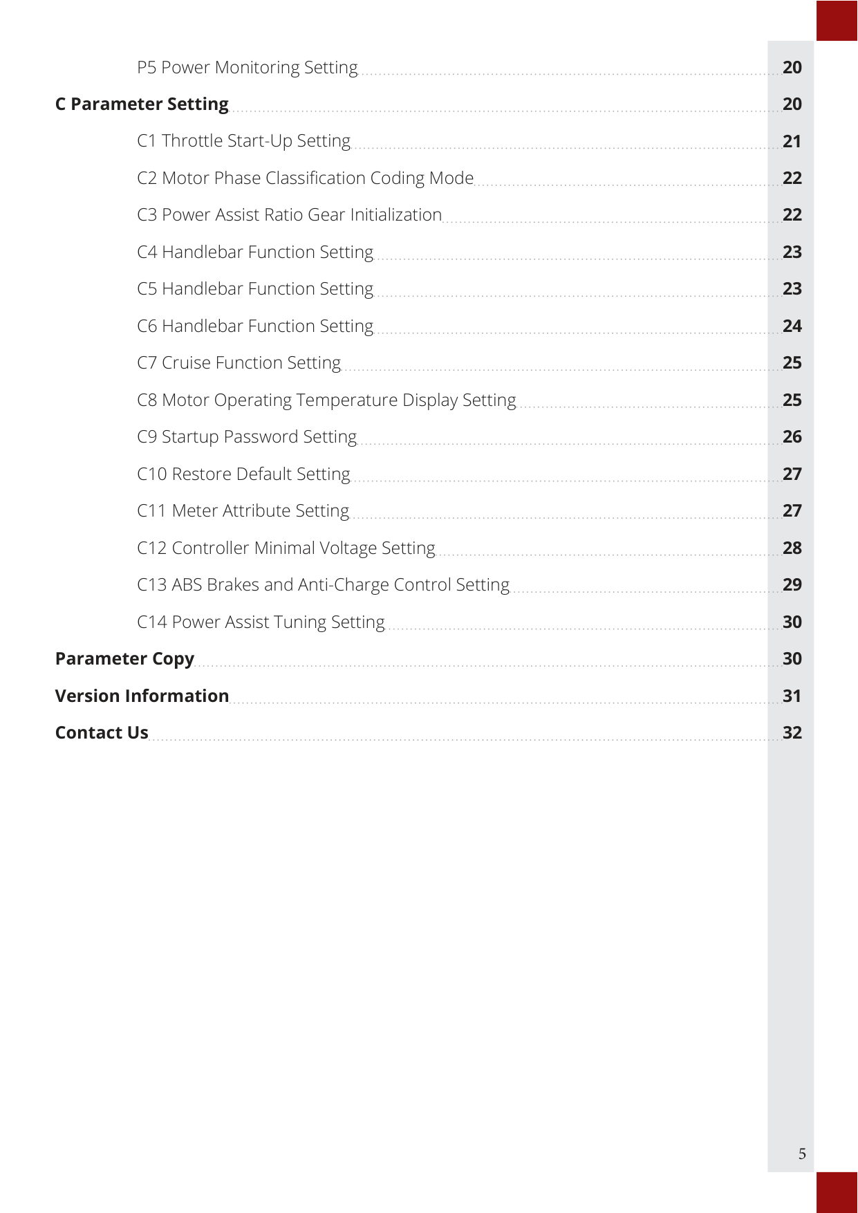
C Parameter Setting 20 C1 Throttle Start-Up Setting 21 C2 Motor Phase Classification Coding Mode 22 C3 Power Assist Ratio Gear Initialization 22 C4 Handlebar Function Setting 23 C5 Handlebar Function Setting 23 C6 Handlebar Function Setting 24 C7 Cruise Function Setting 25 C8 Motor Operating Temperature Display Setting 25 C9 Startup Password Setting 26
###### Parameter Copy 30 Version Information 31 Contact Us 32
INSTALLATION INSTRUCTION
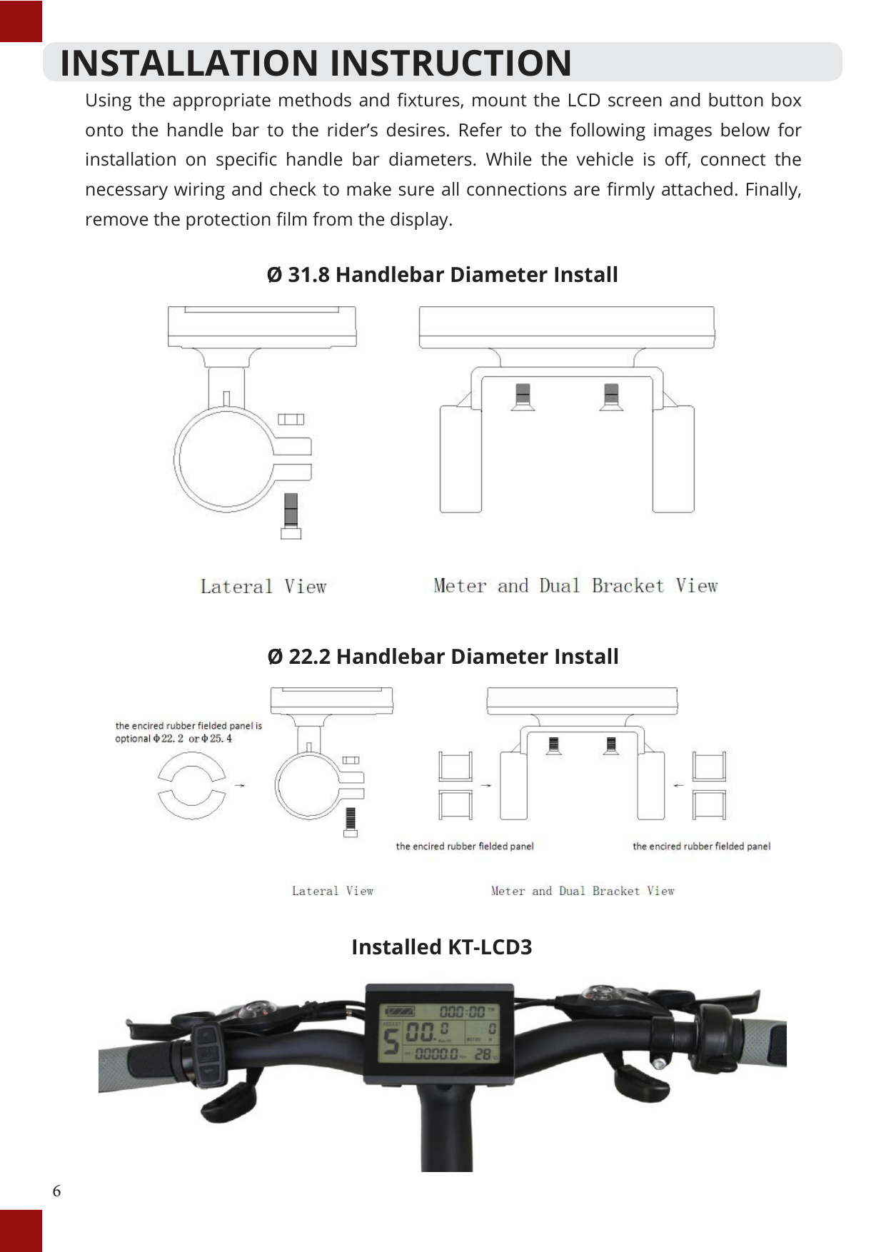
Using the appropriate methods and fixtures, mount the LCD screen and button box onto the handle bar to the rider’s desires. Refer to the following images below for installation on specific handle bar diameters. While the vehicle is off, connect the necessary wiring and check to make sure all connections are firmly attached. Finally, remove the protection film from the display.
Ø 31.8 Handlebar Diameter Install

Ø 22.2 Handlebar Diameter Install

Installed KT-LCD3

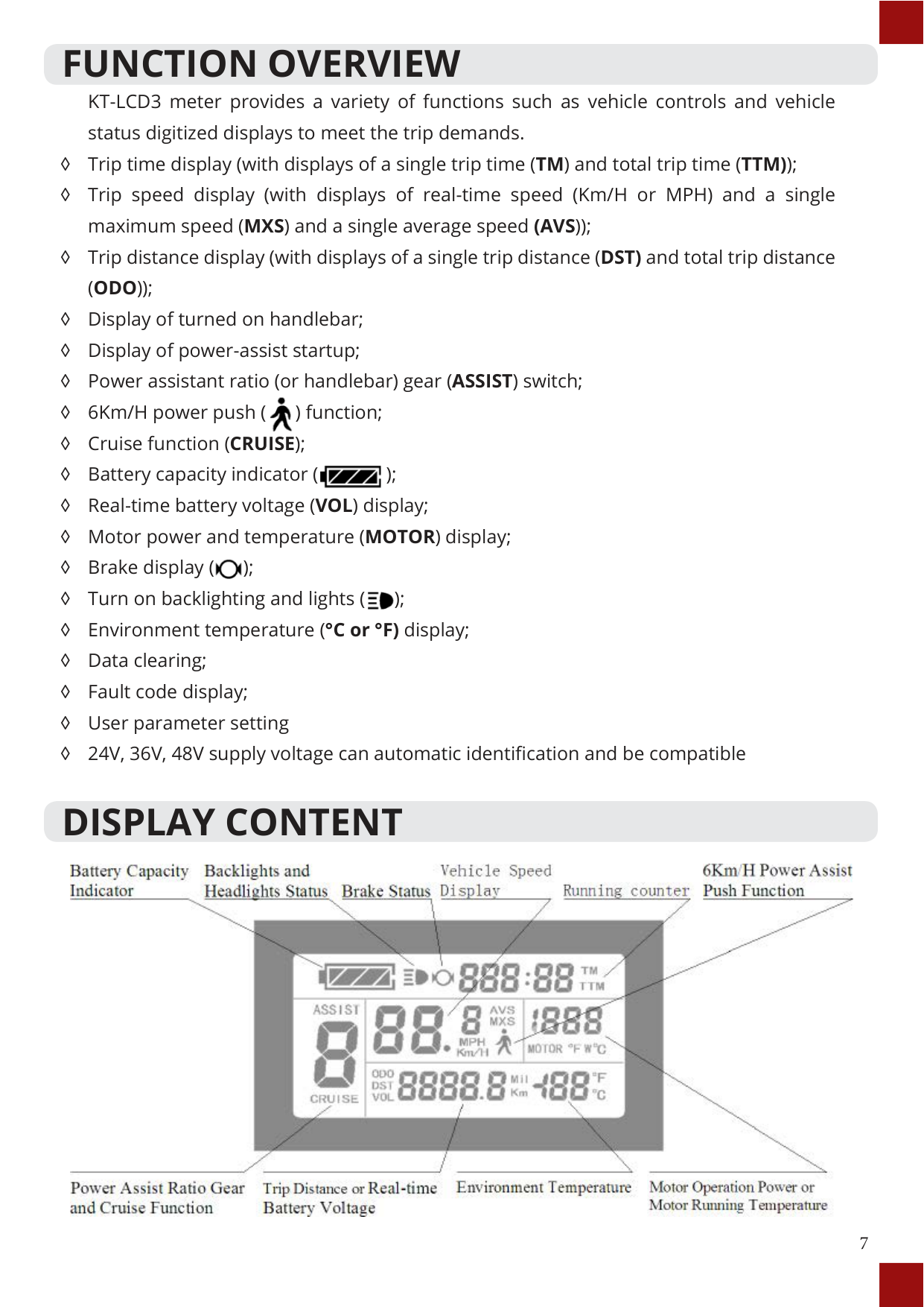
FUNCTION OVERVIEW KT-LCD3 meter provides a variety of functions such as vehicle controls and vehicle status digitized displays to meet the trip demands.
◊ Trip time display (with displays of a single trip time (TM) and total trip time (TTM));
◊ Trip speed display (with displays of real-time speed (Km/H or MPH) and a single maximum speed (MXS) and a single average speed (AVS));
◊ Trip distance display (with displays of a single trip distance (DST) and total trip distance (ODO));
◊ Display of turned on handlebar; ◊ Display of power-assist startup; ◊ Power assistant ratio (or handlebar) gear (ASSIST) switch;

◊ 6Km/H power push ( ) function;
◊ Cruise function (CRUISE);
◊ Battery capacity indicator ( );

◊ Real-time battery voltage (VOL) display;
◊ Motor power and temperature (MOTOR) display;
◊ Brake display ( );

◊ Turn on backlighting and lights ( );

◊ Environment temperature (°C or °F) display;
◊ Data clearing;
◊ Fault code display;
◊ User parameter setting
◊ 24V, 36V, 48V supply voltage can automatic identification and be compatible
DISPLAY CONTENT

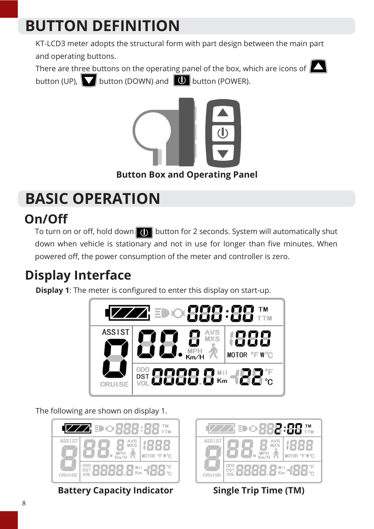
BUTTON DEFINITION KT-LCD3 meter adopts the structural form with part design between the main part and operating buttons. There are three buttons on the operating panel of the box, which are icons of button (UP), button (DOWN) and button (POWER).


Button Box and Operating Panel
BASIC OPERATION
#### On/Off
To turn on or off, hold down button for 2 seconds. System will automatically shut down when vehicle is stationary and not in use for longer than five minutes. When powered off, the power consumption of the meter and controller is zero.

#### Display Interface

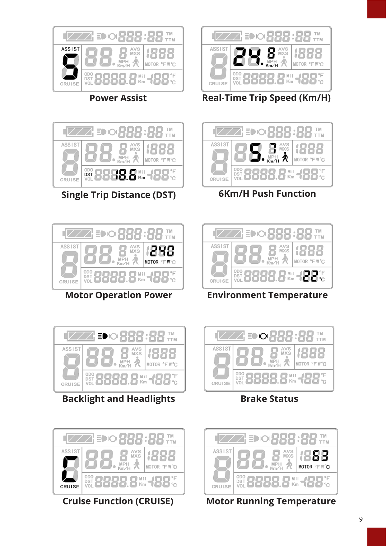
The following are shown on display 1.


##### Battery Capacity Indicator Single Trip Time (TM)


##### Power Assist Real-Time Trip Speed (Km/H)


##### Single Trip Distance (DST) 6Km/H Push Function


##### Motor Operation Power Environment Temperature


##### Backlight and Headlights Brake Status


##### Cruise Function (CRUISE) Motor Running Temperature


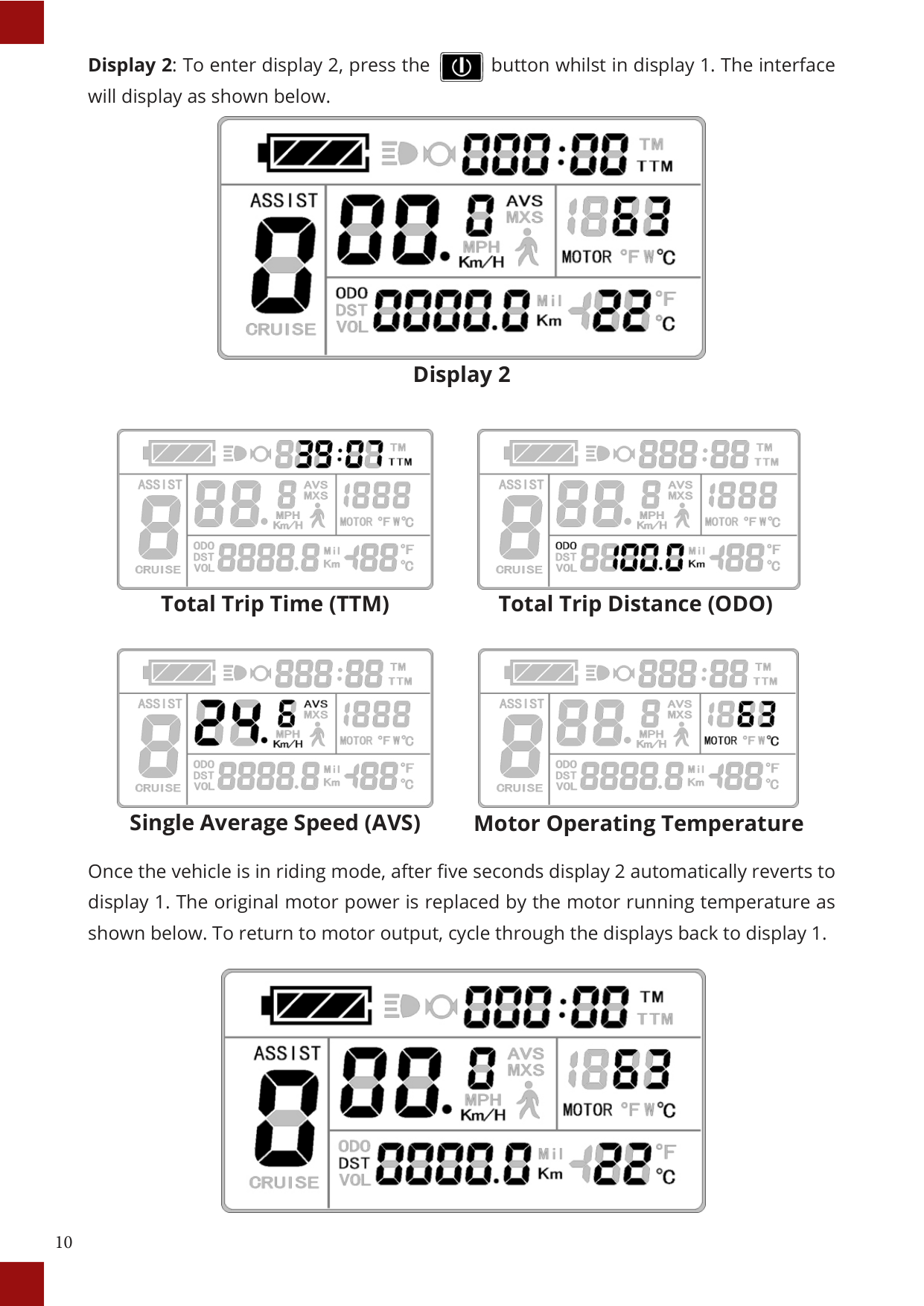
##### Display 2


##### Total Trip Time (TTM) Total Trip Distance (ODO)


##### Single Average Speed (AVS) Motor Operating Temperature
Once the vehicle is in riding mode, after five seconds display 2 automatically reverts to display 1. The original motor power is replaced by the motor running temperature as shown below. To return to motor output, cycle through the displays back to display 1.


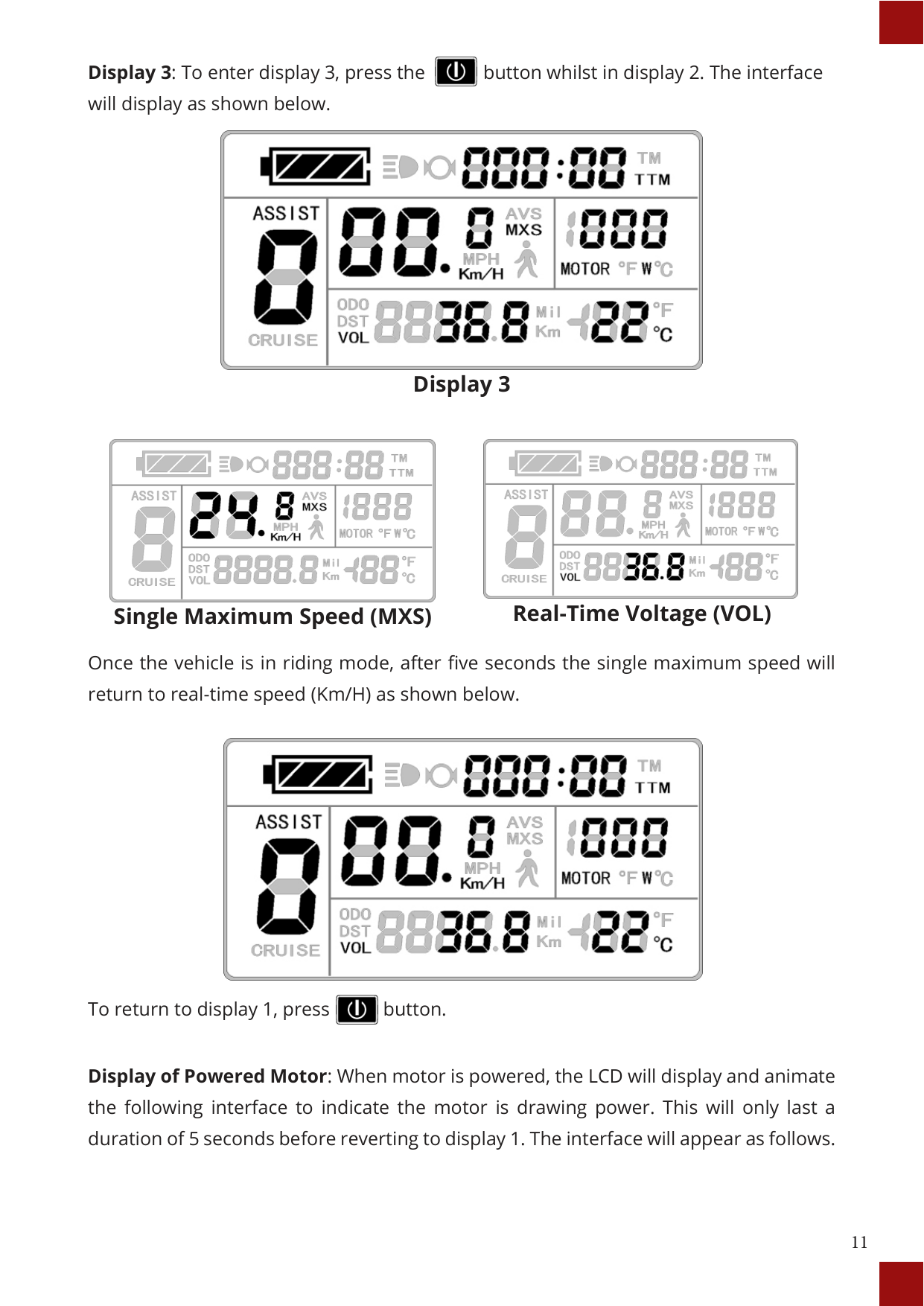
##### Display 3


##### Single Maximum Speed (MXS) Real-Time Voltage (VOL)
Once the vehicle is in riding mode, after five seconds the single maximum speed will return to real-time speed (Km/H) as shown below.


To return to display 1, press button.
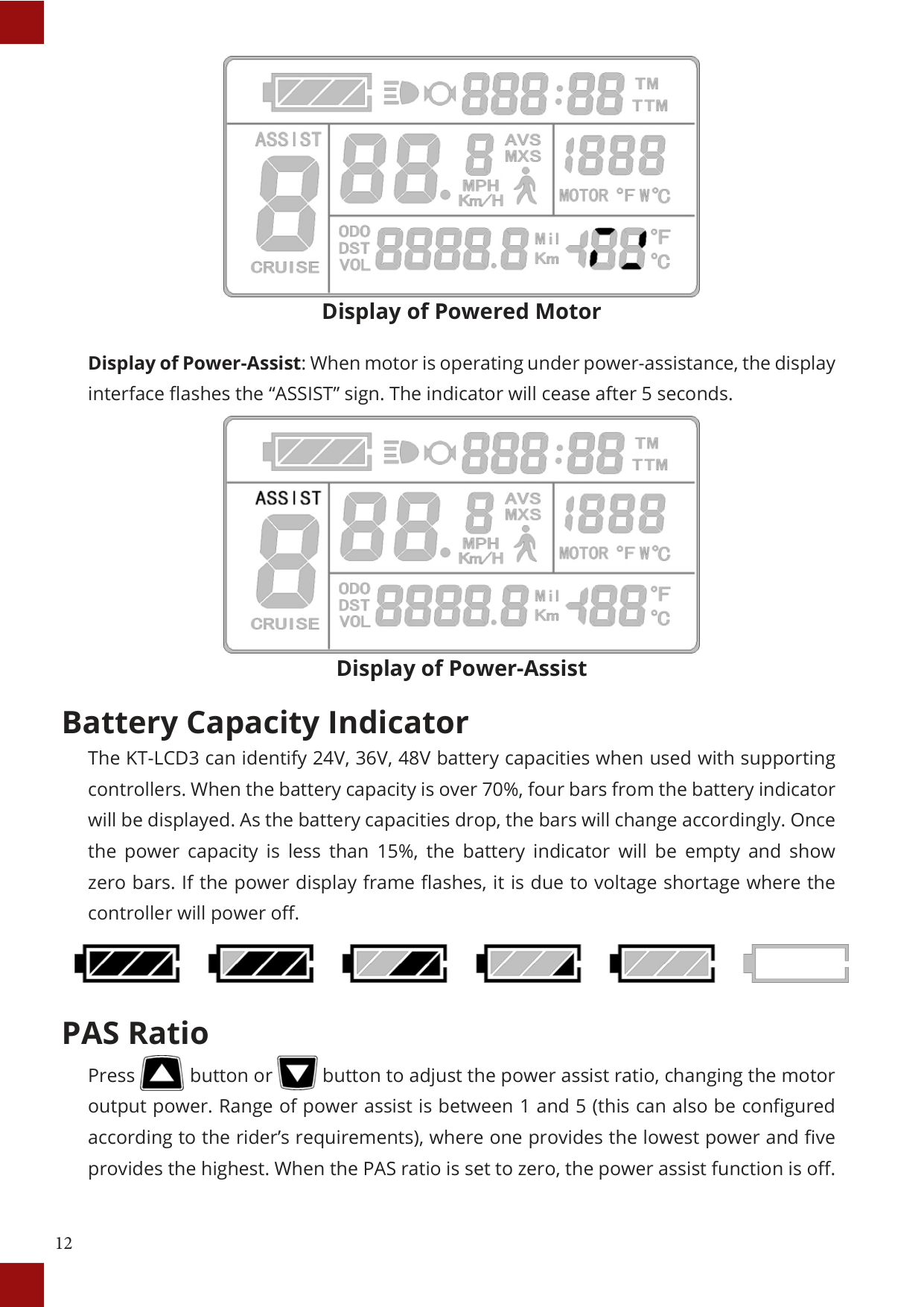
Display of Powered Motor: When motor is powered, the LCD will display and animate the following interface to indicate the motor is drawing power. This will only last a duration of 5 seconds before reverting to display 1. The interface will appear as follows.

Display of Powered Motor
Display of Power-Assist: When motor is operating under power-assistance, the display interface flashes the “ASSIST” sign. The indicator will cease after 5 seconds.

Display of Power-Assist
#### Battery Capacity Indicator
The KT-LCD3 can identify 24V, 36V, 48V battery capacities when used with supporting controllers. When the battery capacity is over 70%, four bars from the battery indicator will be displayed. As the battery capacities drop, the bars will change accordingly. Once the power capacity is less than 15%, the battery indicator will be empty and show zero bars. If the power display frame flashes, it is due to voltage shortage where the controller will power off.

#### PAS Ratio


Press button or button to adjust the power assist ratio, changing the motor output power. Range of power assist is between 1 and 5 (this can also be configured according to the rider’s requirements), where one provides the lowest power and five provides the highest. When the PAS ratio is set to zero, the power assist function is off.
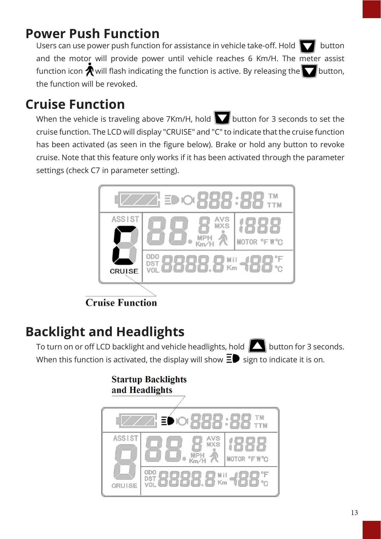
#### Power Push Function

Users can use power push function for assistance in vehicle take-off. Hold button and the motor will provide power until vehicle reaches 6 Km/H. The meter assist function icon will flash indicating the function is active. By releasing the button, the function will be revoked.


#### Cruise Function

When the vehicle is traveling above 7Km/H, hold button for 3 seconds to set the cruise function. The LCD will display "CRUISE" and "C" to indicate that the cruise function has been activated (as seen in the figure below). Brake or hold any button to revoke cruise. Note that this feature only works if it has been activated through the parameter settings (check C7 in parameter setting).

Backlight and Headlights To turn on or off LCD backlight and vehicle headlights, hold button for 3 seconds. When this function is activated, the display will show sign to indicate it is on.


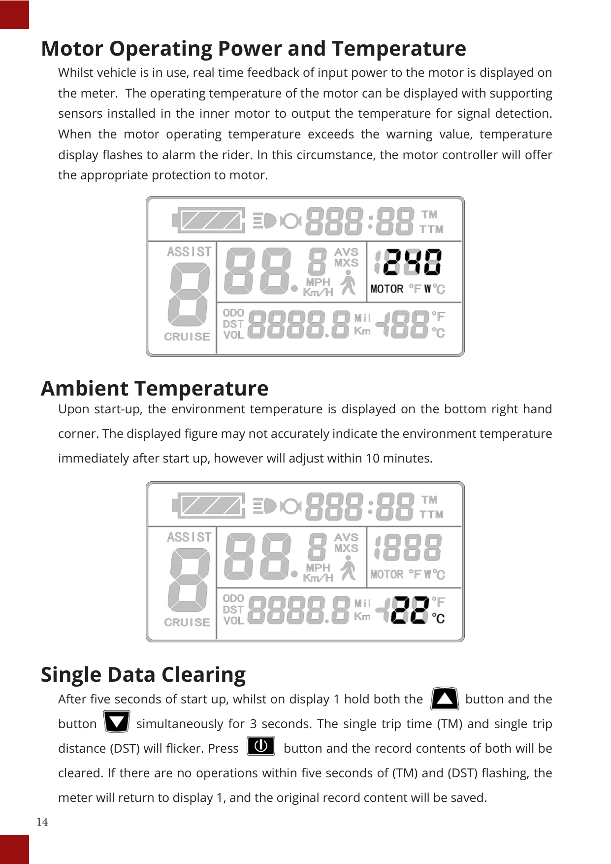
#### Motor Operating Power and Temperature
Whilst vehicle is in use, real time feedback of input power to the motor is displayed on the meter. The operating temperature of the motor can be displayed with supporting sensors installed in the inner motor to output the temperature for signal detection. When the motor operating temperature exceeds the warning value, temperature display flashes to alarm the rider. In this circumstance, the motor controller will offer the appropriate protection to motor.

#### Ambient Temperature
Upon start-up, the environment temperature is displayed on the bottom right hand corner. The displayed figure may not accurately indicate the environment temperature immediately after start up, however will adjust within 10 minutes.

#### Single Data Clearing

After five seconds of start up, whilst on display 1 hold both the button and the button simultaneously for 3 seconds. The single trip time (TM) and single trip distance (DST) will flicker. Press button and the record contents of both will be cleared. If there are no operations within five seconds of (TM) and (DST) flashing, the meter will return to display 1, and the original record content will be saved.


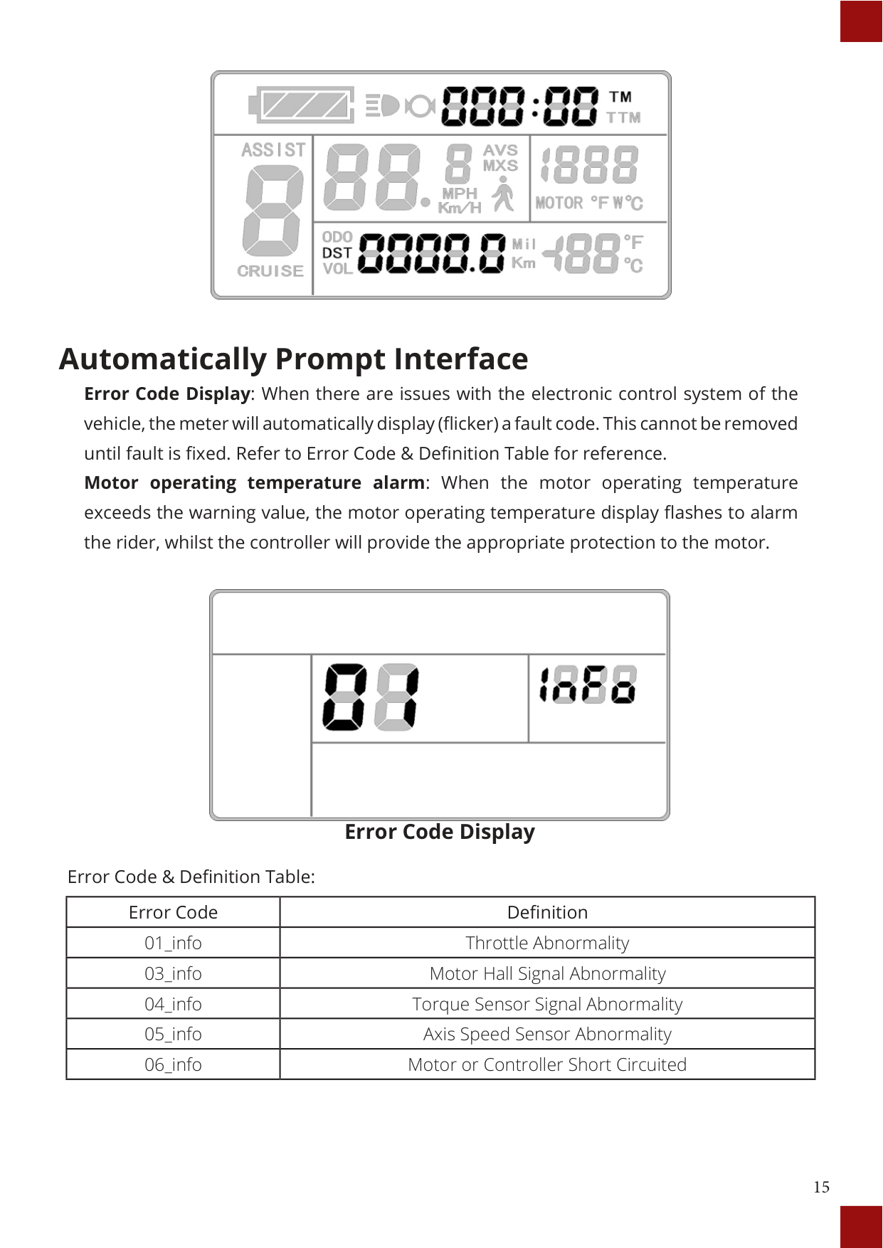
#### Automatically Prompt Interface
Error Code Display: When there are issues with the electronic control system of the vehicle, the meter will automatically display (flicker) a fault code. This cannot be removed until fault is fixed. Refer to Error Code & Definition Table for reference.
Motor operating temperature alarm: When the motor operating temperature exceeds the warning value, the motor operating temperature display flashes to alarm the rider, whilst the controller will provide the appropriate protection to the motor.

Error Code Display
Error Code & Definition Table:
|Error Code|Definition| |---|---| |01_info|Throttle Abnormality| |03_info|Motor Hall Signal Abnormality| |04_info|Torque Sensor Signal Abnormality|
|05_info|Axis Speed Sensor Abnormality| |06_info|Motor or Controller Short Circuited|
USER SETTING PROJECT
The KT-LCD3 meter provides users with 3 depths of settings which are s:


GENERAL PROJECT SETTING
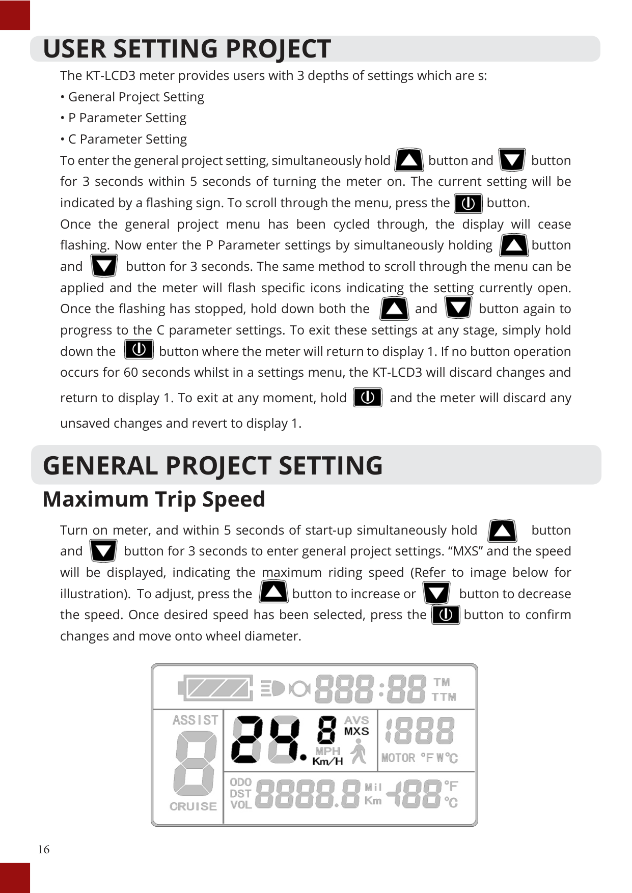
#### Maximum Trip Speed

Turn on meter, and within 5 seconds of start-up simultaneously hold button and button for 3 seconds to enter general project settings. “MXS” and the speed will be displayed, indicating the maximum riding speed (Refer to image below for illustration). To adjust, press the button to increase or button to decrease the speed. Once desired speed has been selected, press the button to confirm changes and move onto wheel diameter.


#### Wheel Diameter

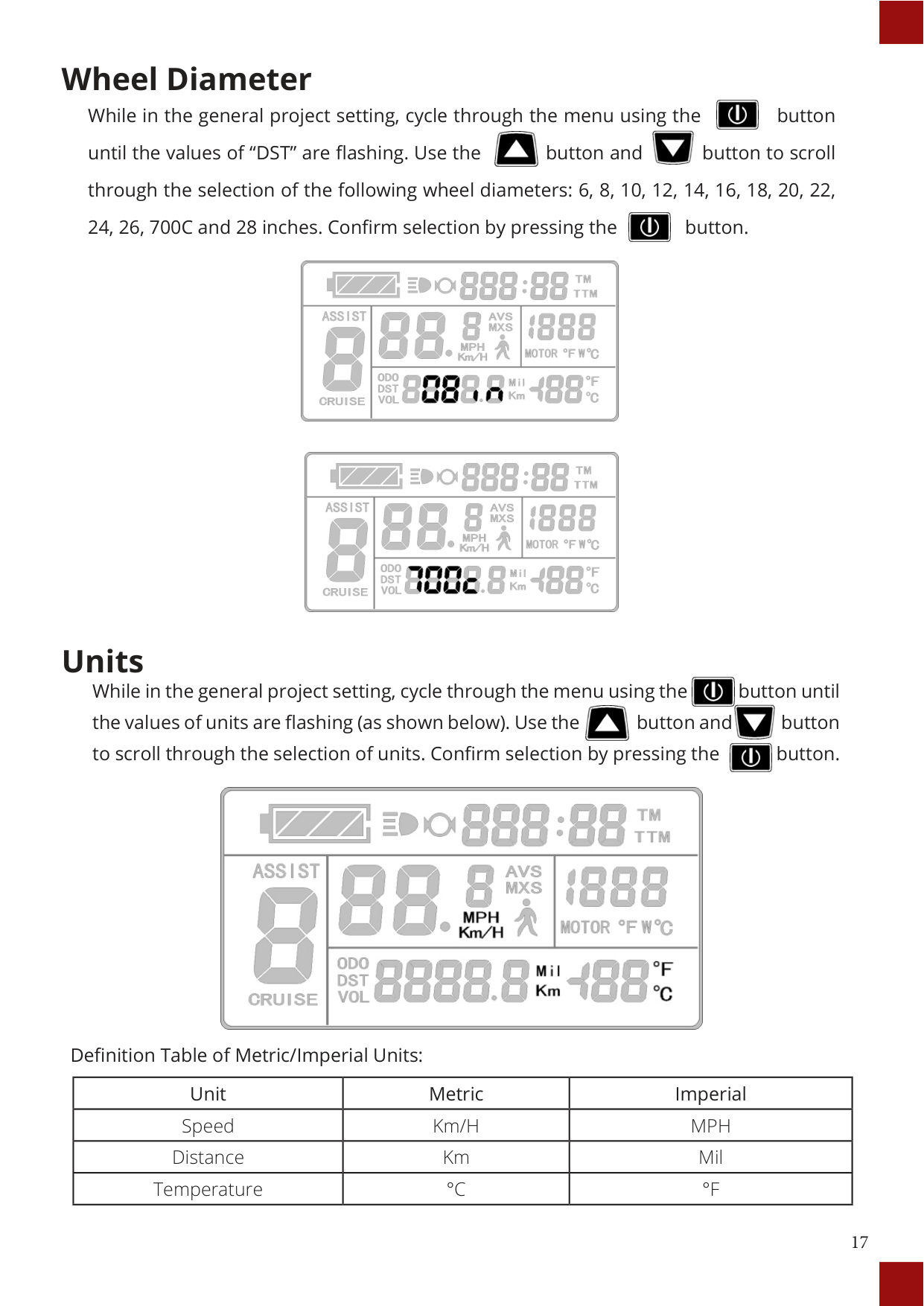
While in the general project setting, cycle through the menu using the button until the values of “DST” are flashing. Use the button and button to scroll through the selection of the following wheel diameters: 6, 8, 10, 12, 14, 16, 18, 20, 22, 24, 26, 700C and 28 inches. Confirm selection by pressing the button.


#### Units

While in the general project setting, cycle through the menu using the button until the values of units are flashing (as shown below). Use the button and button to scroll through the selection of units. Confirm selection by pressing the button.


Definition Table of Metric/Imperial Units:
|Unit|Metric|Imperial| |---|---|---| |Speed|Km/H|MPH| |Distance|Km|Mil| |Temperature|°C|°F|
P PARAMETER SETTING Enter the P Parameter settings by cycling through the General Project Settings to the end (when display ceases flashing) and simultaneously holding button and button for 3 seconds. If required to exit at any parameter, hold button for 2 seconds. Use the button and button to select the value and confirm selection by pressing the button. The parameter will be saved and the meter will enter the next P parameter settings.


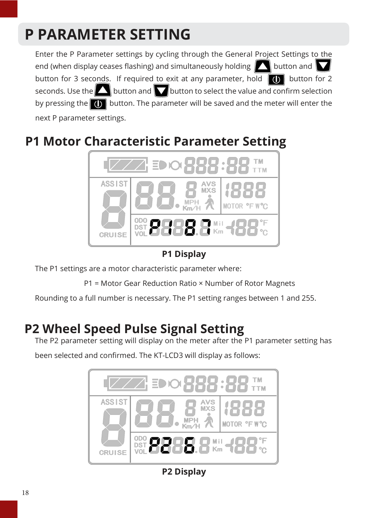
#### P1 Motor Characteristic Parameter Setting

P1 Display
The P1 settings are a motor characteristic parameter where: P1 = Motor Gear Reduction Ratio × Number of Rotor Magnets Rounding to a full number is necessary. The P1 setting ranges between 1 and 255.
#### P2 Wheel Speed Pulse Signal Setting
The P2 parameter setting will display on the meter after the P1 parameter setting has been selected and confirmed. The KT-LCD3 will display as follows:

##### P2 Display


P3 Display

##### P4 Display

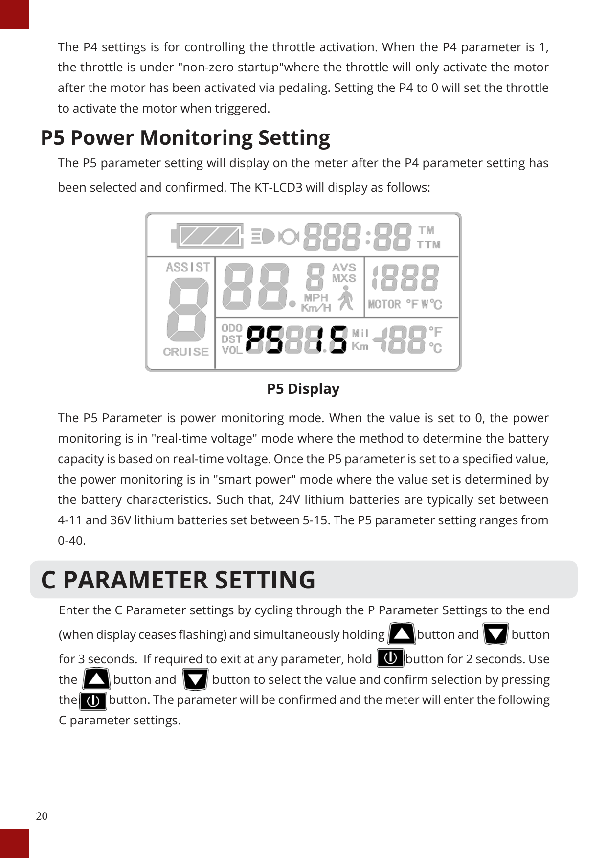
##### P5 Display
The P5 Parameter is power monitoring mode. When the value is set to 0, the power monitoring is in "real-time voltage" mode where the method to determine the battery capacity is based on real-time voltage. Once the P5 parameter is set to a specified value, the power monitoring is in "smart power" mode where the value set is determined by the battery characteristics. Such that, 24V lithium batteries are typically set between 4-11 and 36V lithium batteries set between 5-15. The P5 parameter setting ranges from 0-40.
C PARAMETER SETTING
Enter the C Parameter settings by cycling through the P Parameter Settings to the end (when display ceases flashing) and simultaneously holding button and button for 3 seconds. If required to exit at any parameter, hold button for 2 seconds. Use the button and button to select the value and confirm selection by pressing the button. The parameter will be confirmed and the meter will enter the following C parameter settings.


#### C1 Throttle Start-Up Setting
The C1 parameter setting will display on the meter after the P Parameter settings. The KT-LCD3 will display as follows:

##### C1 Display
C1 settings are the power assist sensor parameters. Its definition is shown in the following table. As it can be seen from the table, the values for this parameter range from 0 to 7.
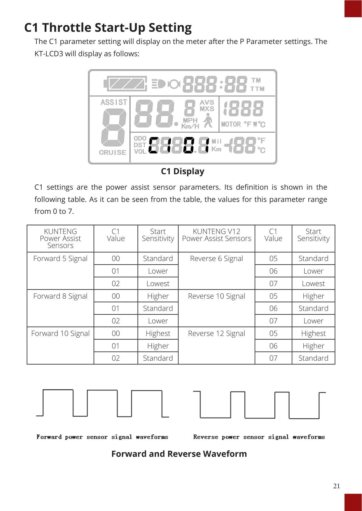
|KUNTENG Power Assist Sensors|C1 Value|Start Sensitivity|KUNTENG V12 Power Assist Sensors|C1 Value|Start Sensitivity| |---|---|---|---|---|---| |Forward 5 Signal|00|Standard|Reverse 6 Signal|05|Standard| |Forward 5 Signal|01|Lower|Reverse 6 Signal|06|Lower| |Forward 5 Signal|02|Lowest|Reverse 6 Signal|07|Lowest| |Forward 8 Signal|00|Higher|Reverse 10 Signal|05|Higher| |Forward 8 Signal|01|Standard|Reverse 10 Signal|06|Standard| |Forward 8 Signal|02|Lower|Reverse 10 Signal|07|Lower| |Forward 10 Signal|00|Highest|Reverse 12 Signal|05|Highest| |Forward 10 Signal|01|Higher|Reverse 12 Signal|06|Higher| |Forward 10 Signal|02|Standard|Reverse 12 Signal|07|Standard|

Forward and Reverse Waveform
#### C2 Motor Phase Classification Coding Mode

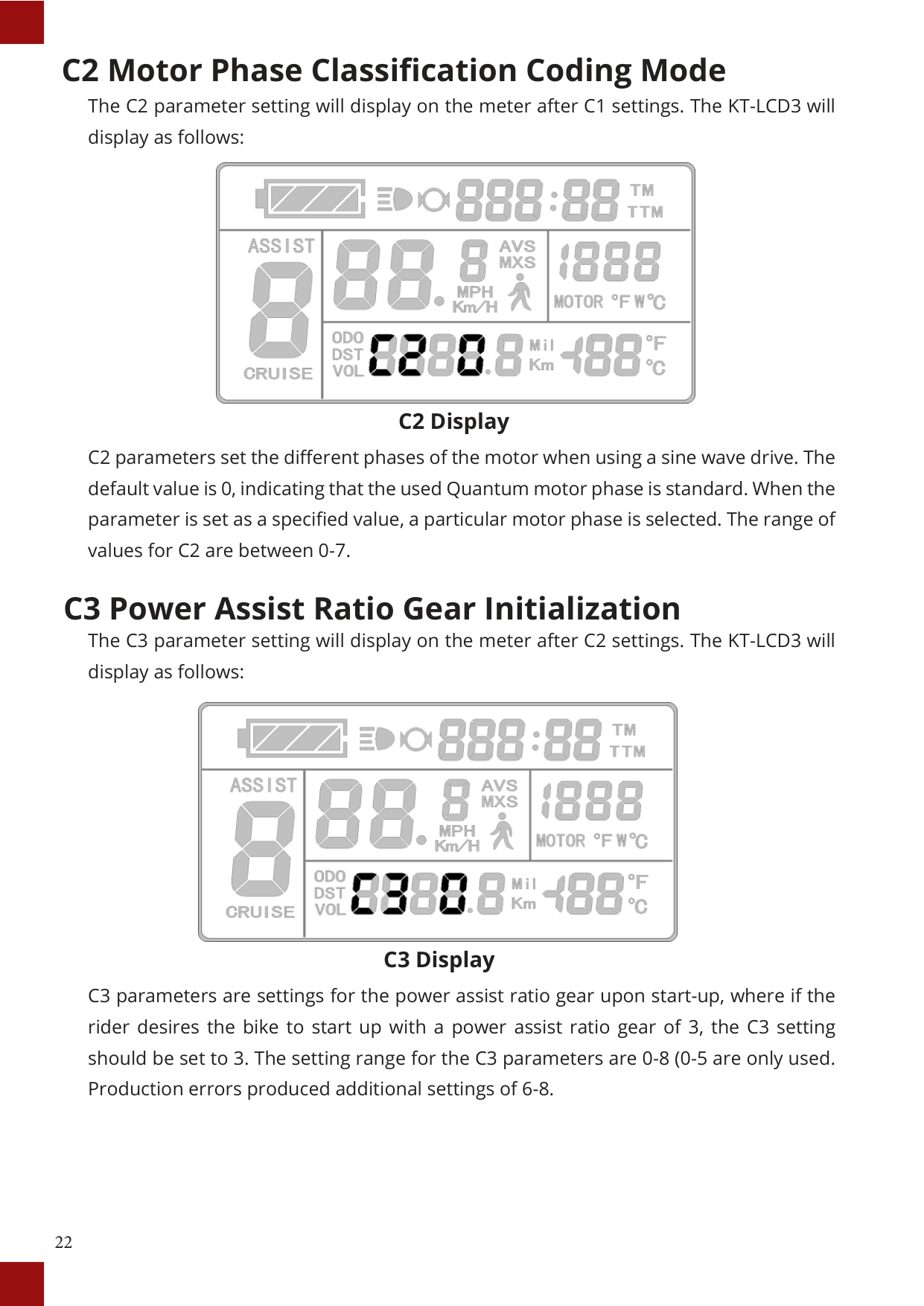
C2 Display
C2 parameters set the different phases of the motor when using a sine wave drive. The default value is 0, indicating that the used Quantum motor phase is standard. When the parameter is set as a specified value, a particular motor phase is selected. The range of values for C2 are between 0-7.
#### C3 Power Assist Ratio Gear Initialization

C3 Display
C3 parameters are settings for the power assist ratio gear upon start-up, where if the rider desires the bike to start up with a power assist ratio gear of 3, the C3 setting should be set to 3. The setting range for the C3 parameters are 0-8 (0-5 are only used. Production errors produced additional settings of 6-8.
C4 Handlebar Function Setting The C4 parameter setting will display on the meter after C3 settings. The KT-LCD3 will display as follows:

C4 Display C4 settings are for the handlebar functions. The setting range is 0-4. This is accompanied by a table below, defining each value.
|C4 Value|Throttle startup Mode P4 = 0|Throttle Startup Mode P4 = 1| |---|---|---| |0|Zero startup handlebar|Non-zero startup| |1|Zero startup, throttle speed limited to 6km/h|Throttle limited to 6km/h before pedaling and provides full speed after pedal assist| |2|Zero startup, throttle speed limited to rider's specification|Non-zero startup, throttle speed limited to rider's specification| |3|Zero startup, zero gear effectively|Retain| |4|Throttle gears is distinguished according to the display meter|Throttle gears is distinguished according to the display meter| |5|Retain|Retain|
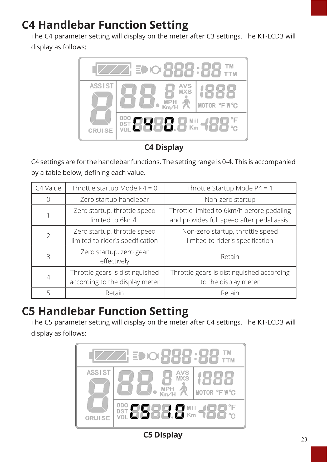
C5 Handlebar Function Setting The C5 parameter setting will display on the meter after C4 settings. The KT-LCD3 will display as follows:

##### C5 Display
C5 settings are for controlling the maximum operating current. The default value is 10 and value ranges from 0 to 10. Refer to table below for definition of each value.
|C5 Value|Maximum Current Value (A)| |---|---| |00|Undefined| |01|Undefined| |02|Undefined| |03|Maximum Current Value ÷ 2.00| |04|Maximum Current Value ÷ 1.50| |05|Maximum Current Value ÷ 1.33| |06|Maximum Current Value ÷ 1.25| |07|Maximum Current Value ÷ 1.20| |08|Maximum Current Value ÷ 1.15| |09|Maximum Current Value ÷ 1.10| |10|Maximum Current Value|
C6 Handlebar Function Setting The C6 parameter setting will display on the meter after C5 settings. The KT-LCD3 will display as follows:
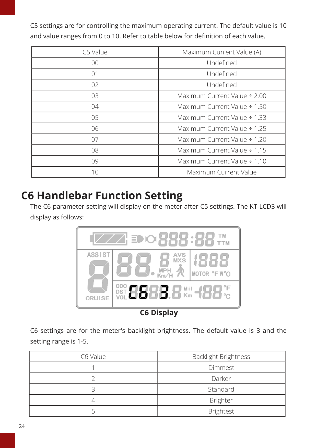

##### C6 Display
C6 settings are for the meter's backlight brightness. The default value is 3 and the setting range is 1-5.
|C6 Value|Backlight Brightness| |---|---| |1|Dimmest| |2|Darker| |3|Standard| |4|Brighter| |5|Brightest|
#### C7 Cruise Function Setting
The C7 parameter setting will display on the meter after C6 settings. The KT-LCD3 will display as follows:

##### C7 Display
The cruise function settings can be found in C7. Refer to the following table for definitions of C7 values.
|C7 Value|Cruise Function| |---|---| |0|Disabled| |1|Enabled|
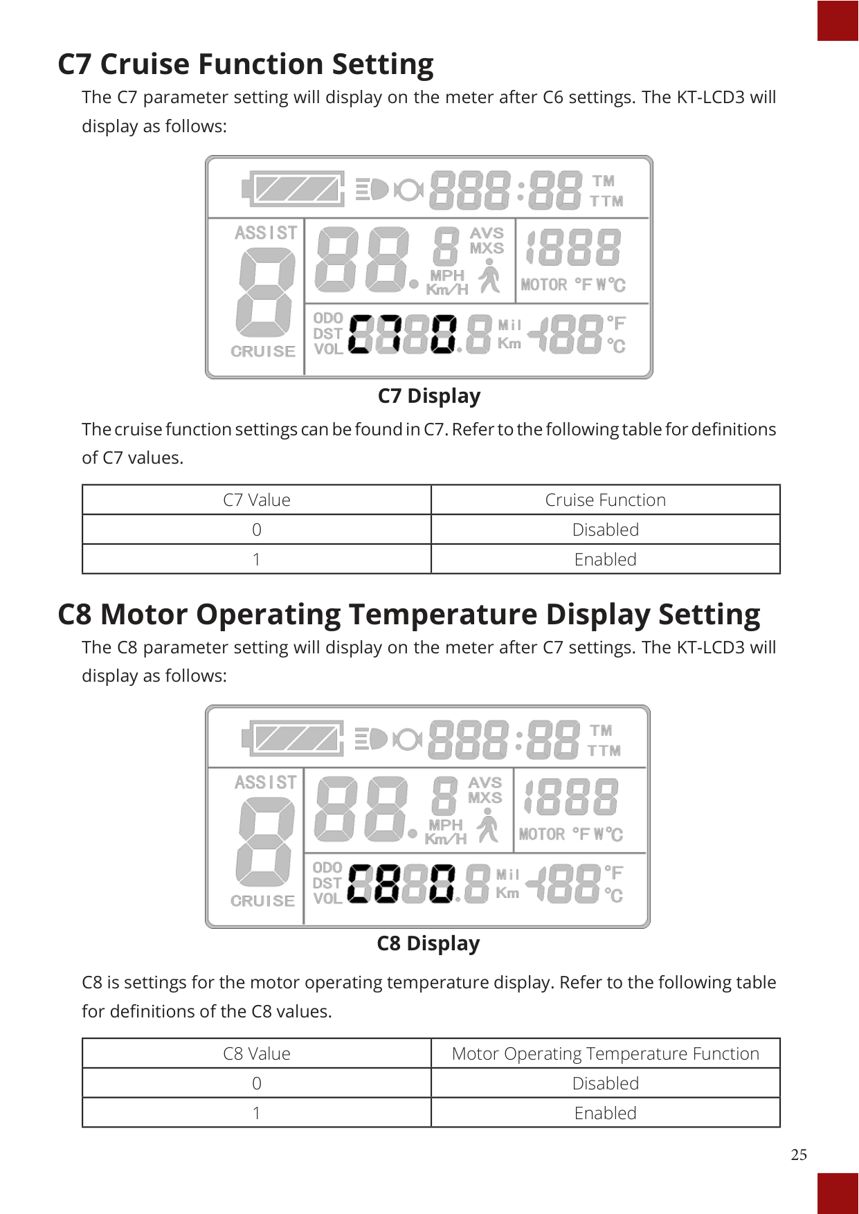
#### C8 Motor Operating Temperature Display Setting
The C8 parameter setting will display on the meter after C7 settings. The KT-LCD3 will display as follows:

##### C8 Display
C8 is settings for the motor operating temperature display. Refer to the following table for definitions of the C8 values.
|C8 Value|Motor Operating Temperature Function| |---|---| |0|Disabled| |1|Enabled|
#### C9 Startup Password Setting
The C9 parameter setting will display on the meter after C8 settings. The KT-LCD3 will display as follows:
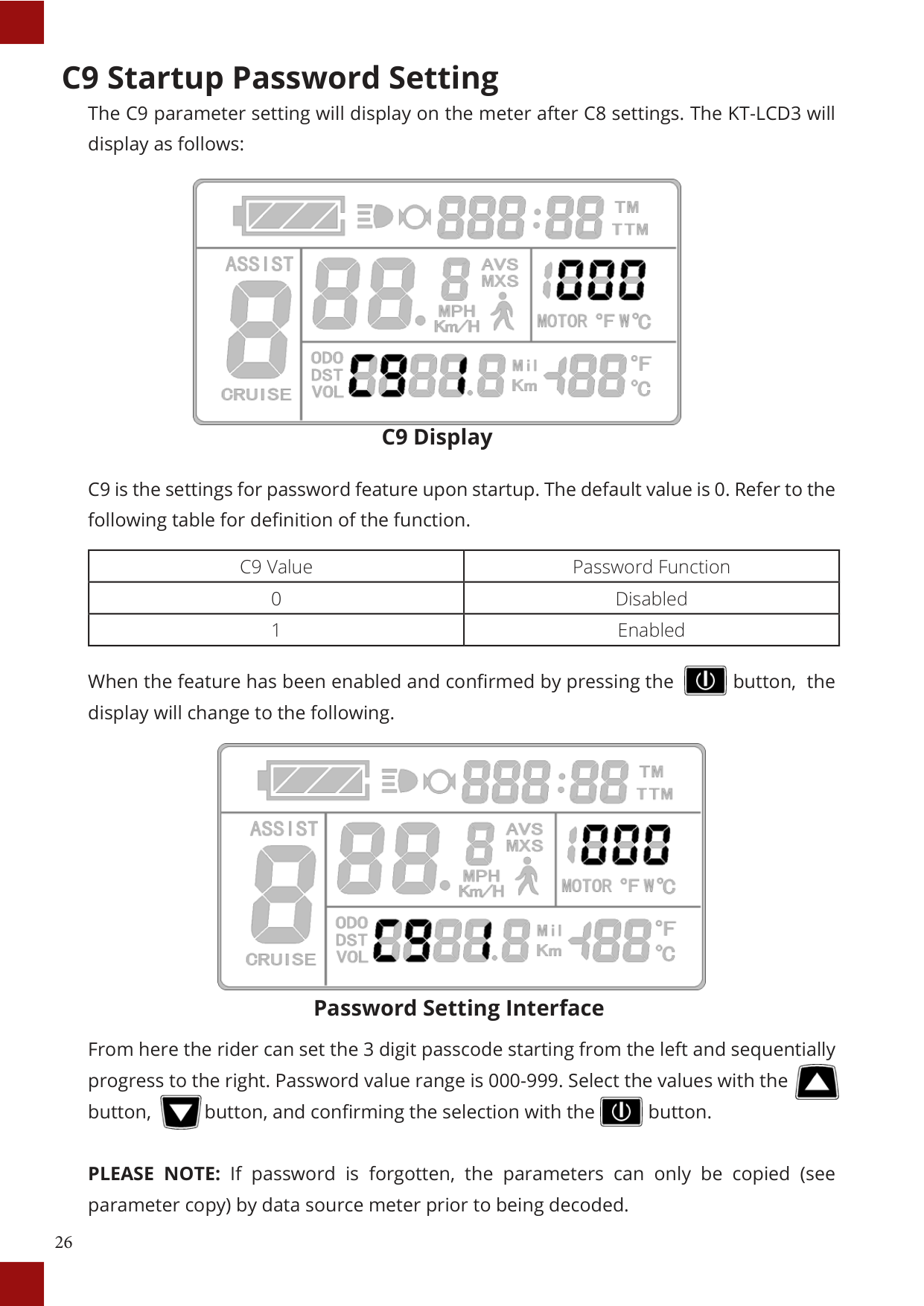

C9 Display
C9 is the settings for password feature upon startup. The default value is 0. Refer to the following table for definition of the function.
|C9 Value|Password Function| |---|---| |0|Disabled| |1|Enabled|

When the feature has been enabled and confirmed by pressing the button, the display will change to the following.

Password Setting Interface
From here the rider can set the 3 digit passcode starting from the left and sequentially progress to the right. Password value range is 000-999. Select the values with the button, button, and confirming the selection with the button.


PLEASE NOTE: If password is forgotten, the parameters can only be copied (see parameter copy) by data source meter prior to being decoded.
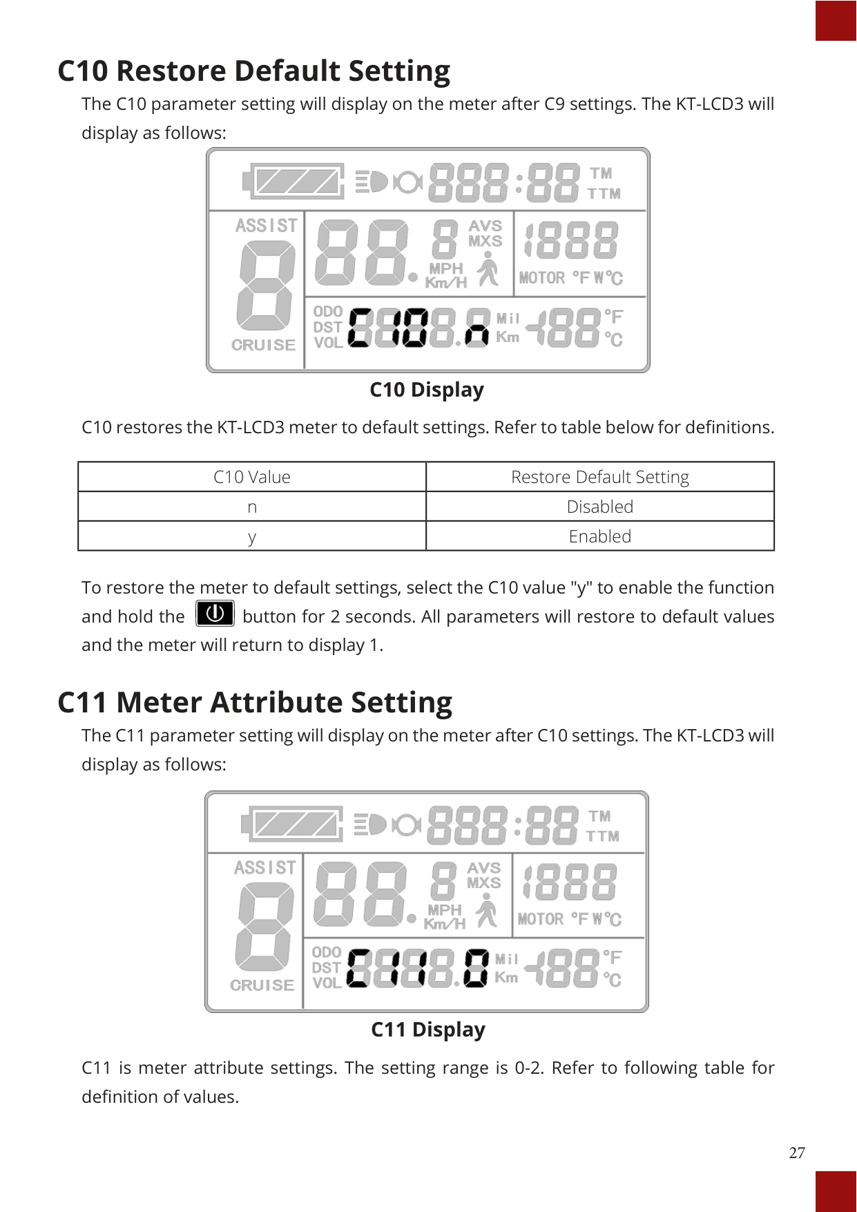
#### C10 Restore Default Setting
The C10 parameter setting will display on the meter after C9 settings. The KT-LCD3 will display as follows:

C10 Display
|C10 Value|Restore Default Setting| |---|---| |n|Disabled| |y|Enabled|
To restore the meter to default settings, select the C10 value "y" to enable the function and hold the button for 2 seconds. All parameters will restore to default values and the meter will return to display 1.


The C11 parameter setting will display on the meter after C10 settings. The KT-LCD3 will display as follows:
##### C11 Display
|C8 Value|Meter Attribute| |---|---| |0|Meter uses LCD3 new version of communication protocol, compatible with LCD1 and LCD3| |1|Meter uses LCD1 and LCD2 old version communication protocol, it is not compatible with LCD3| |2|As data source for copying parameters, the meter transfers the new LCD3 parameter to other meters|
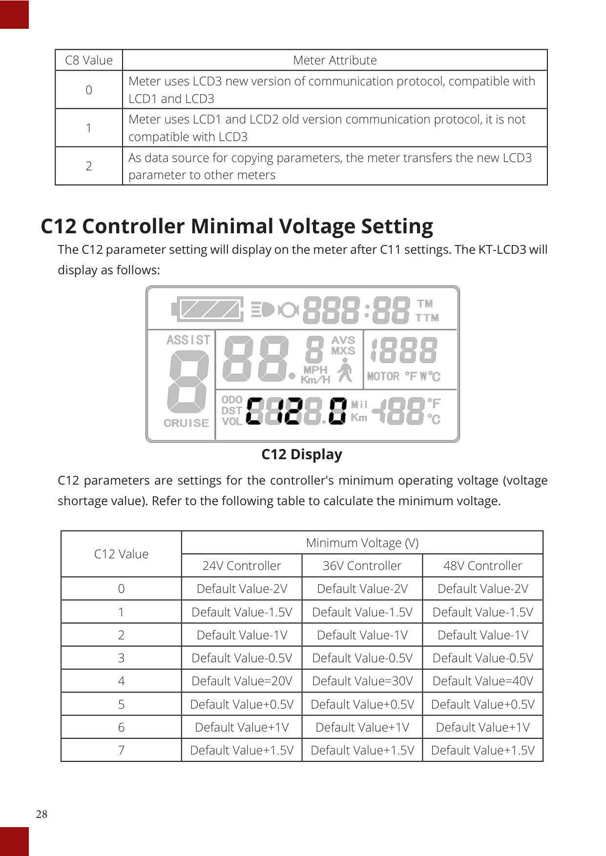
#### C12 Controller Minimal Voltage Setting
The C12 parameter setting will display on the meter after C11 settings. The KT-LCD3 will display as follows:

##### C12 Display
|C12 Value|Minimum Voltage (V)|Minimum Voltage (V)|Minimum Voltage (V)| |---|---|---|---| |C12 Value|24V Controller|36V Controller|48V Controller| |0|Default Value-2V|Default Value-2V|Default Value-2V| |1|Default Value-1.5V|Default Value-1.5V|Default Value-1.5V| |2|Default Value-1V|Default Value-1V|Default Value-1V| |3|Default Value-0.5V|Default Value-0.5V|Default Value-0.5V| |4|Default Value=20V|Default Value=30V|Default Value=40V| |5|Default Value+0.5V|Default Value+0.5V|Default Value+0.5V| |6|Default Value+1V|Default Value+1V|Default Value+1V| |7|Default Value+1.5V|Default Value+1.5V|Default Value+1.5V|
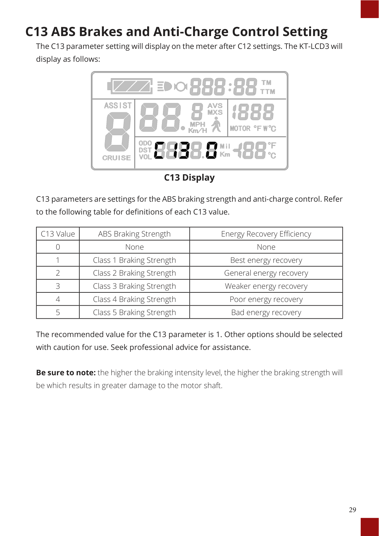
#### C13 ABS Brakes and Anti-Charge Control Setting
The C13 parameter setting will display on the meter after C12 settings. The KT-LCD3 will display as follows:

##### C13 Display
|C13 Value|ABS Braking Strength|Energy Recovery Efficiency| |---|---|---| |0|None|None| |1|Class 1 Braking Strength|Best energy recovery| |2|Class 2 Braking Strength|General energy recovery| |3|Class 3 Braking Strength|Weaker energy recovery| |4|Class 4 Braking Strength|Poor energy recovery| |5|Class 5 Braking Strength|Bad energy recovery|
The recommended value for the C13 parameter is 1. Other options should be selected with caution for use. Seek professional advice for assistance.
Be sure to note: the higher the braking intensity level, the higher the braking strength will be which results in greater damage to the motor shaft.
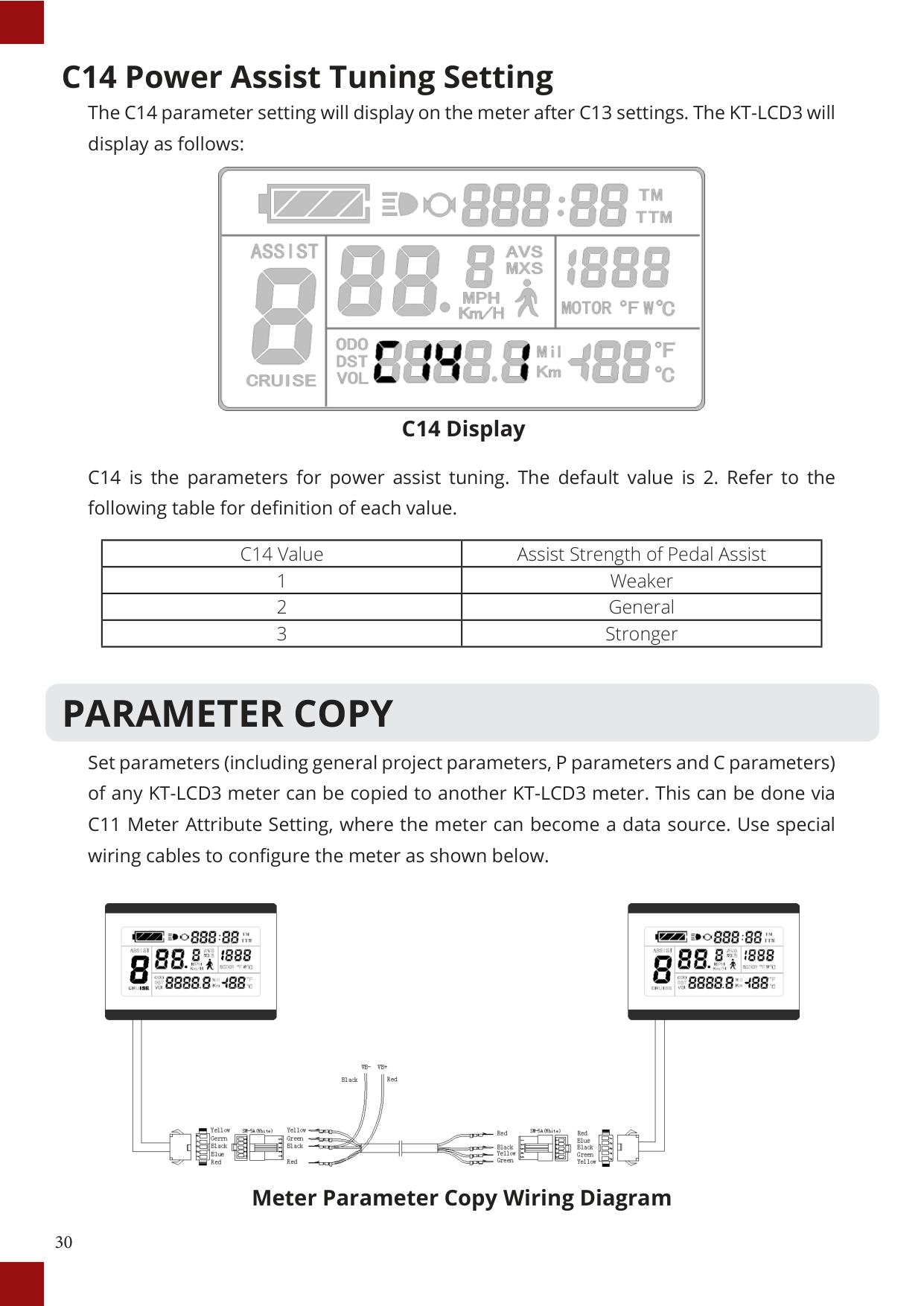
#### C14 Power Assist Tuning Setting
The C14 parameter setting will display on the meter after C13 settings. The KT-LCD3 will display as follows:

##### C14 Display
C14 is the parameters for power assist tuning. The default value is 2. Refer to the following table for definition of each value.
|C14 Value|Assist Strength of Pedal Assist| |---|---|
|1|Weaker| |2|General| |3|Stronger|
PARAMETER COPY
Set parameters (including general project parameters, P parameters and C parameters) of any KT-LCD3 meter can be copied to another KT-LCD3 meter. This can be done via C11 Meter Attribute Setting, where the meter can become a data source. Use special wiring cables to configure the meter as shown below.

##### Meter Parameter Copy Wiring Diagram

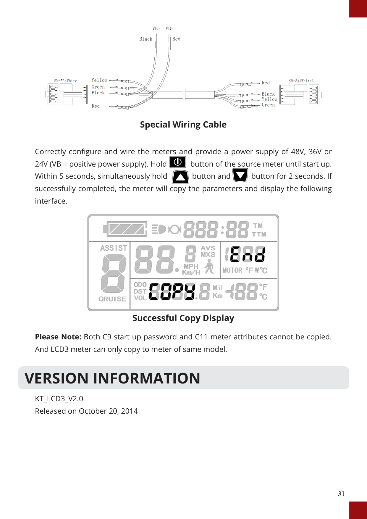
Special Wiring Cable
Correctly configure and wire the meters and provide a power supply of 48V, 36V or 24V (VB + positive power supply). Hold button of the source meter until start up. Within 5 seconds, simultaneously hold button and button for 2 seconds. If successfully completed, the meter will copy the parameters and display the following interface.


Successful Copy Display
Please Note: Both C9 start up password and C11 meter attributes cannot be copied. And LCD3 meter can only copy to meter of same model.
VERSION INFORMATION
KT_LCD3_V2.0 Released on October 20, 2014