
Anthony P0117 Cylinder Head Temperature Sensor
Ask AI
— answers from the official manualAnswers from the official manual.
Common questions
Common Questions
10 totalWhat does DTC P0117 indicate?
DTC P0117 indicates a short in the engine coolant temperature sensor circuit that lasts for at least 0.5 seconds (Page 2)
How do I troubleshoot DTC P0117?
To troubleshoot, read engine coolant temperature values using a Techstream and check for an output below 0.14V, indicating circuit performance issues related to the sensor (Pages 2-5)
What causes DTC P0117?
DTC P0117 is set when there is a short in the engine coolant temperature sensor circuit for at least 0.5 seconds (Page 2)
What does an open or short circuit issue usually display on the Techstream?
An open circuit typically reads -40°C (-40°F), while a short circuit shows 140°C (284°F) or higher temperatures during a malfunction check with Techstream (Page 6)
How do I confirm if an open circuit issue is present?
To confirm an open circuit, disconnect the engine coolant temperature sensor connector and reconnect terminals THW and E2 from the wire harness side; a reading of over 140°C (284°F) indicates no open circuit (Page 6)
How can I check for an open connection in DTC P0117?
Checking involves confirming a good connection at the engine coolant temperature sensor connector and measuring resistance between terminal pairs to ensure it is below 1Ω (Page 8)
Full Manual
9 pages
||Last Modified: 11-3-2017| |---|
|6.8:8.0.48| |---|
|Doc ID: RM000000PF50APX| |---|
|Model Year Start: 2010| |---|
|Model: Prius| |---|
|Prod Date Range: [04/2009 - ]| |---|
|Title: 2ZR-FXE ENGINE CONTROL: SFI SYSTEM: P0115,P0117,P0118; Engine Coolant Temperature Circuit Malfunction; 2010 MY Prius [04/2009 - ]| |---| | |---|
||DTC| |---|
|P0115| |---|
|Engine Coolant Temperature Circuit Malfunction| |---| | |---|
||DTC| |---|
|P0117| |---|
|Engine Coolant Temperature Circuit Low Input| |---| | |---|
||DTC| |---|
|P0118| |---|
|Engine Coolant Temperature Circuit High Input| |---| | |---|
DESCRIPTION
A thermistor, whose resistance value varies according to the engine coolant temperature, is built into the engine coolant temperature sensor.
The structure of the sensor and its connection to the ECM are the same as those of the intake air temperature sensor.
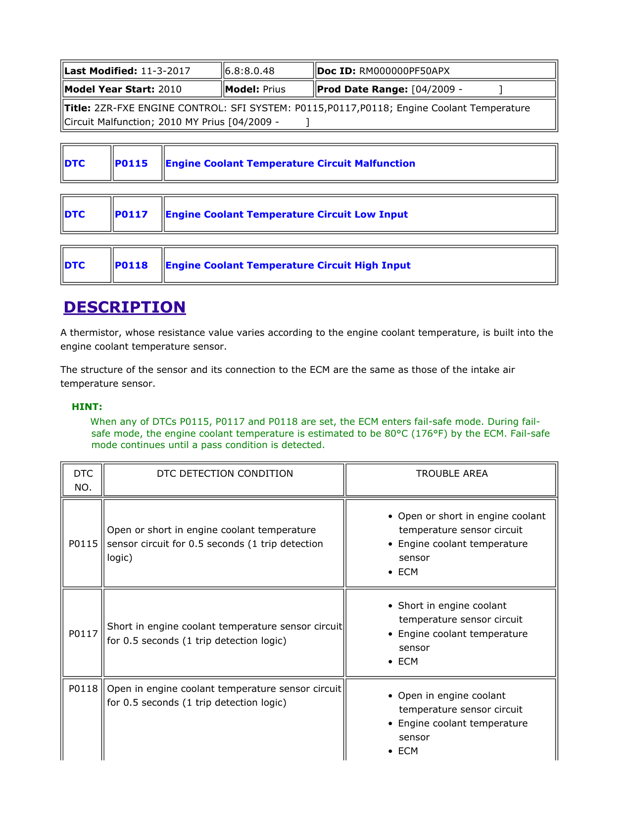
HINT: When any of DTCs P0115, P0117 and P0118 are set, the ECM enters fail-safe mode. During failsafe mode, the engine coolant temperature is estimated to be 80°C (176°F) by the ECM. Fail-safe mode continues until a pass condition is detected.
|DTC NO.| |---|
|DTC DETECTION CONDITION| |---|
|TROUBLE AREA| |---|
|P0115| |---|
|Open or short in engine coolant temperature sensor circuit for 0.5 seconds (1 trip detection logic)| |---|
|• Open or short in engine coolant temperature sensor circuit
• Engine coolant temperature sensor
• ECM
| |---|
|P0117| |---|
|Short in engine coolant temperature sensor circuit for 0.5 seconds (1 trip detection logic)| |---|
|• Short in engine coolant temperature sensor circuit
• Engine coolant temperature sensor
• ECM
| |---|
P0118 Open in engine coolant temperature sensor circuit for 0.5 seconds (1 trip detection logic)
||DTC NO.| |---|
|DTC DETECTION CONDITION| |---|
|TROUBLE AREA| |---| | |---|
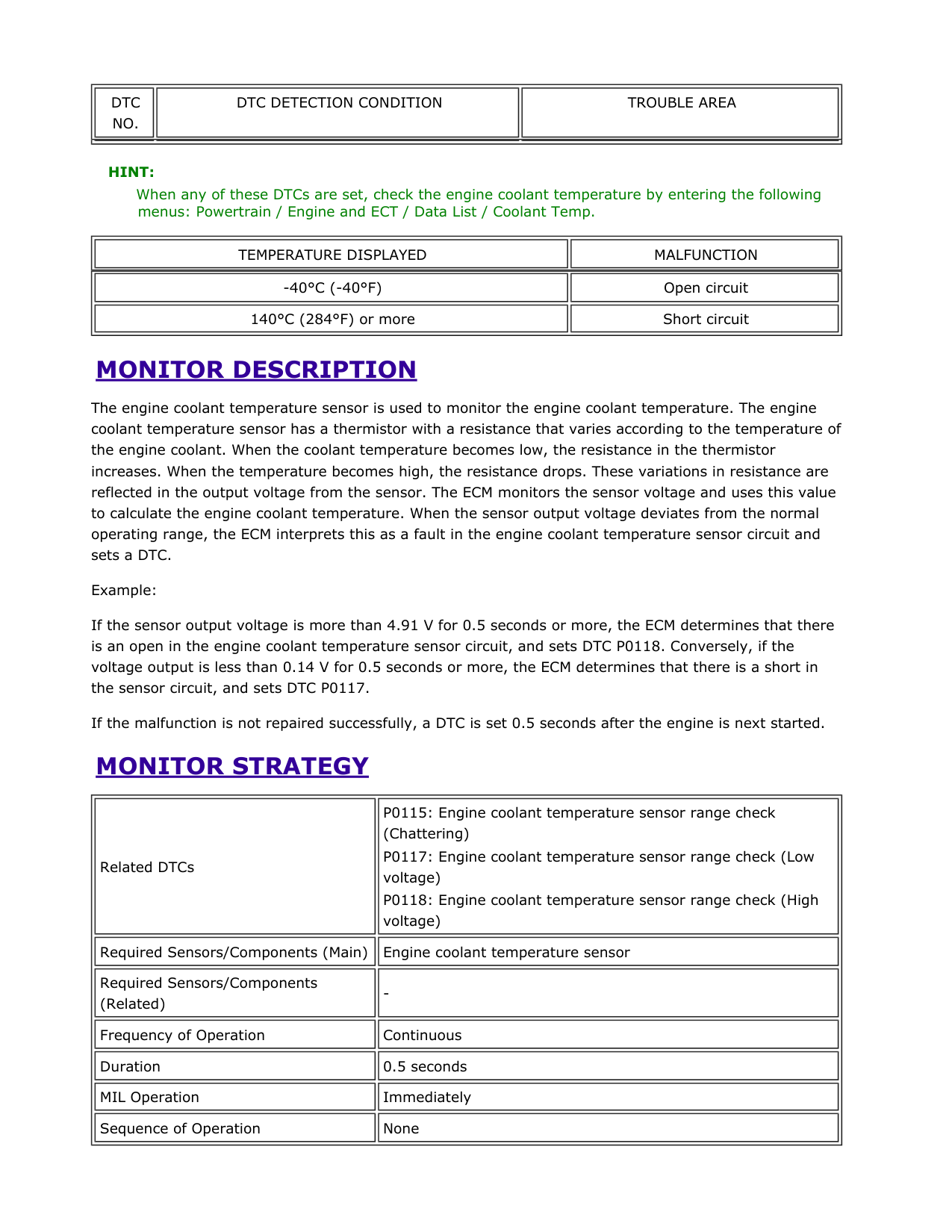
HINT: When any of these DTCs are set, check the engine coolant temperature by entering the following menus: Powertrain / Engine and ECT / Data List / Coolant Temp.
||TEMPERATURE DISPLAYED| |---|
|MALFUNCTION| |---| | |---| ||-40°C (-40°F)| |---|
|Open circuit| |---|
|140°C (284°F) or more| |---|
|Short circuit| |---| |
MONITOR DESCRIPTION
The engine coolant temperature sensor is used to monitor the engine coolant temperature. The engine coolant temperature sensor has a thermistor with a resistance that varies according to the temperature of the engine coolant. When the coolant temperature becomes low, the resistance in the thermistor increases. When the temperature becomes high, the resistance drops. These variations in resistance are reflected in the output voltage from the sensor. The ECM monitors the sensor voltage and uses this value to calculate the engine coolant temperature. When the sensor output voltage deviates from the normal operating range, the ECM interprets this as a fault in the engine coolant temperature sensor circuit and sets a DTC.
Example:
If the sensor output voltage is more than 4.91 V for 0.5 seconds or more, the ECM determines that there is an open in the engine coolant temperature sensor circuit, and sets DTC P0118. Conversely, if the voltage output is less than 0.14 V for 0.5 seconds or more, the ECM determines that there is a short in the sensor circuit, and sets DTC P0117.
If the malfunction is not repaired successfully, a DTC is set 0.5 seconds after the engine is next started.
MONITOR STRATEGY
||Related DTCs| |---|
|P0115: Engine coolant temperature sensor range check (Chattering)
P0117: Engine coolant temperature sensor range check (Low voltage)
P0118: Engine coolant temperature sensor range check (High voltage)
| |---|
|Required Sensors/Components (Main)| |---|
|Engine coolant temperature sensor| |---|
|Required Sensors/Components (Related)| |---|
|-| |---|
|Frequency of Operation| |---|
|Continuous| |---|
|Duration| |---|
|0.5 seconds| |---|
|MIL Operation| |---|
|Immediately| |---|
|Sequence of Operation| |---|
|None| |---| | |---|
TYPICAL ENABLING CONDITIONS
||Monitor runs whenever following DTCs are not present| |---|
|None| |---| | |---|
TYPICAL MALFUNCTION THRESHOLDS
P0115
||Engine coolant temperature sensor voltage| |---|
|Less than 0.14 V, or more than 4.91 V| |---| | |---|
||Engine coolant temperature sensor voltage| |---|
|Less than 0.14 V| |---| | |---|
||Engine coolant temperature sensor voltage| |---|
|More than 4.91 V| |---| | |---|
COMPONENT OPERATING RANGE
||Engine coolant temperature sensor voltage| |---|
|0.14 to 4.91 V| |---| | |---|
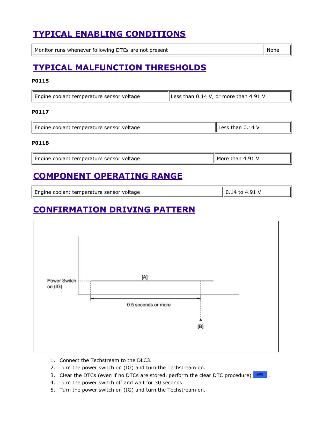
CONFIRMATION DRIVING PATTERN
|| |---|

HINT: If a DTC is not output, perform the following procedure.
HINT:
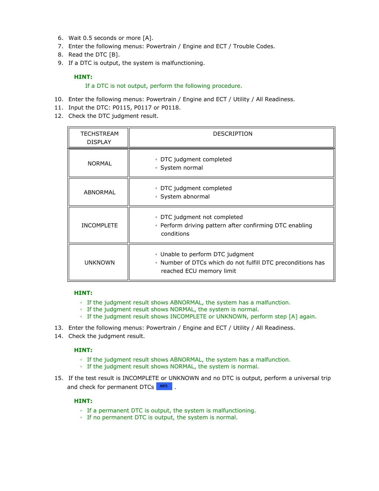
||TECHSTREAM DISPLAY| |---|
|DESCRIPTION| |---| | |---| ||NORMAL| |---|
|◦ DTC judgment completed
◦ System normal
| |---|
|ABNORMAL| |---|
|◦ DTC judgment completed
◦ System abnormal
| |---|
|INCOMPLETE| |---|
|◦ DTC judgment not completed
◦ Perform driving pattern after confirming DTC enabling conditions
| |---|
|UNKNOWN| |---|
|◦ Unable to perform DTC judgment
◦ Number of DTCs which do not fulfill DTC preconditions has reached ECU memory limit
| |---| |

HINT:
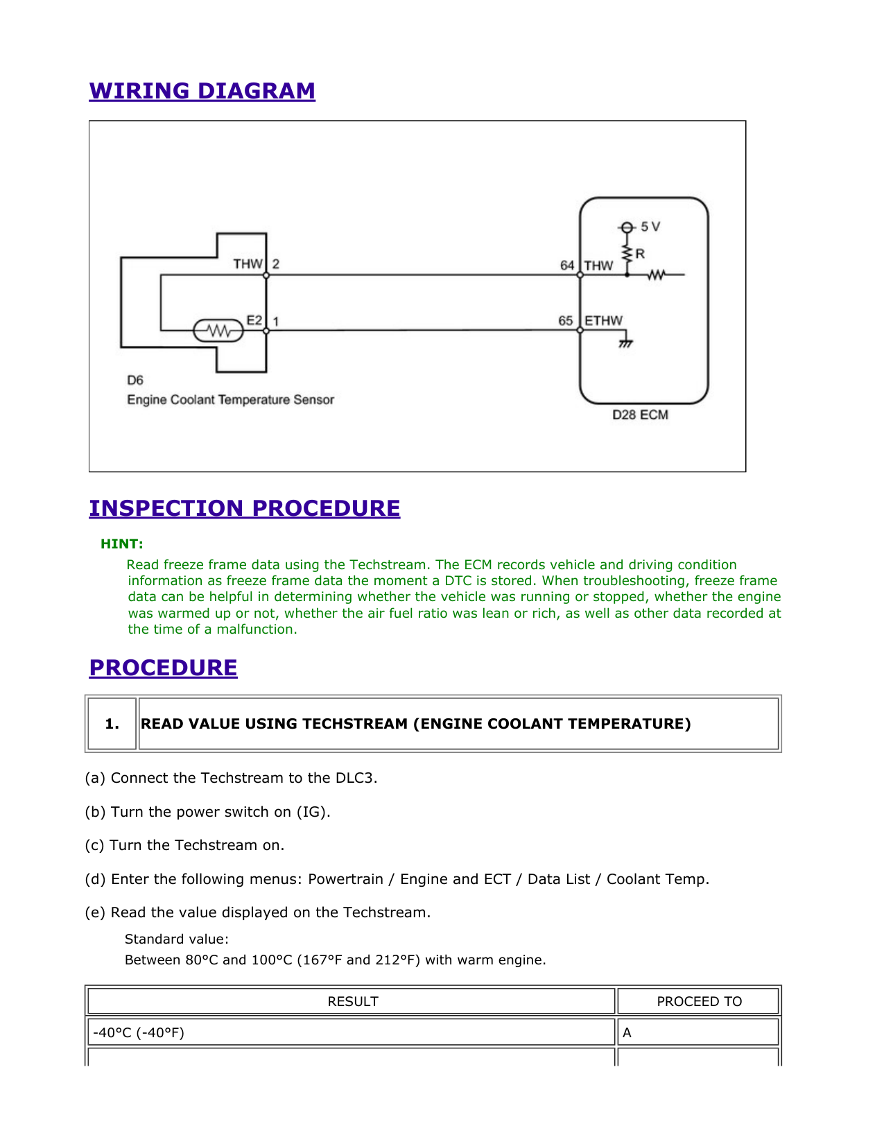
WIRING DIAGRAM
|| |---|
INSPECTION PROCEDURE
HINT: Read freeze frame data using the Techstream. The ECM records vehicle and driving condition information as freeze frame data the moment a DTC is stored. When troubleshooting, freeze frame data can be helpful in determining whether the vehicle was running or stopped, whether the engine was warmed up or not, whether the air fuel ratio was lean or rich, as well as other data recorded at the time of a malfunction.
PROCEDURE
||1.| |---|
|READ VALUE USING TECHSTREAM (ENGINE COOLANT TEMPERATURE)| |---| | |---|
Standard value: Between 80°C and 100°C (167°F and 212°F) with warm engine.
|RESULT| |---|
|PROCEED TO| |---|
|-40°C (-40°F)| |---|
|A| |---|
||RESULT| |---|
|PROCEED TO| |---| ||RESULT| |---|
|PROCEED TO| |---| | |---|---| |140°C (284°F) or more|B| ||Between 80°C and 100°C (176°F and 212°F)| |---|
|C| |---| ||Between 80°C and 100°C (176°F and 212°F)| |---|
|C| |---| |
HINT:
A

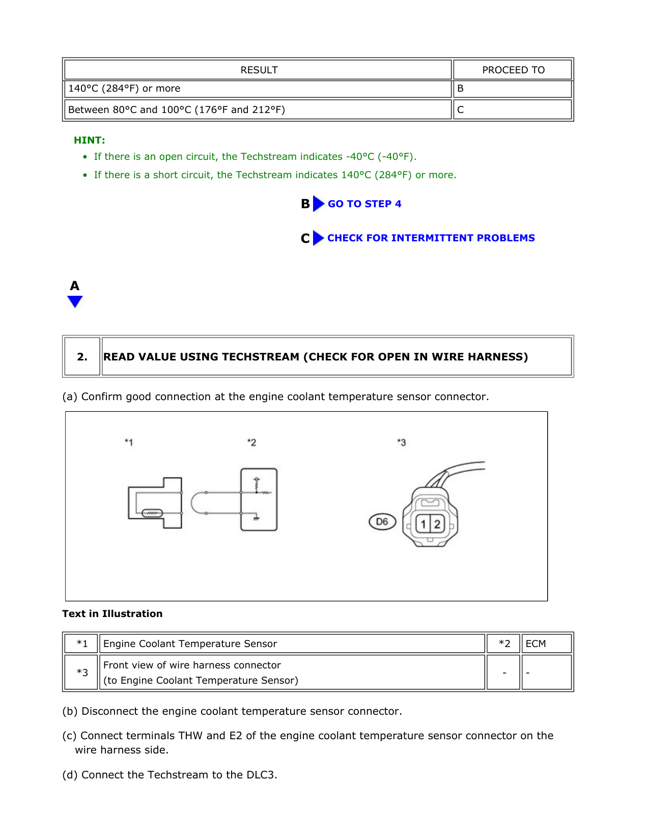
||2.| |---|
|READ VALUE USING TECHSTREAM (CHECK FOR OPEN IN WIRE HARNESS)| |---| | |---|
|| |---|
Text in Illustration
||*1| |---|
|Engine Coolant Temperature Sensor| |---|
|*2| |---|
|ECM| |---|
|*3| |---|
|Front view of wire harness connector (to Engine Coolant Temperature Sensor)| |---|
|-| |---|
|-| |---| | |---|
Standard: 140°C (284°F) or more
OK REPLACE ENGINE COOLANT TEMPERATURESENSOR
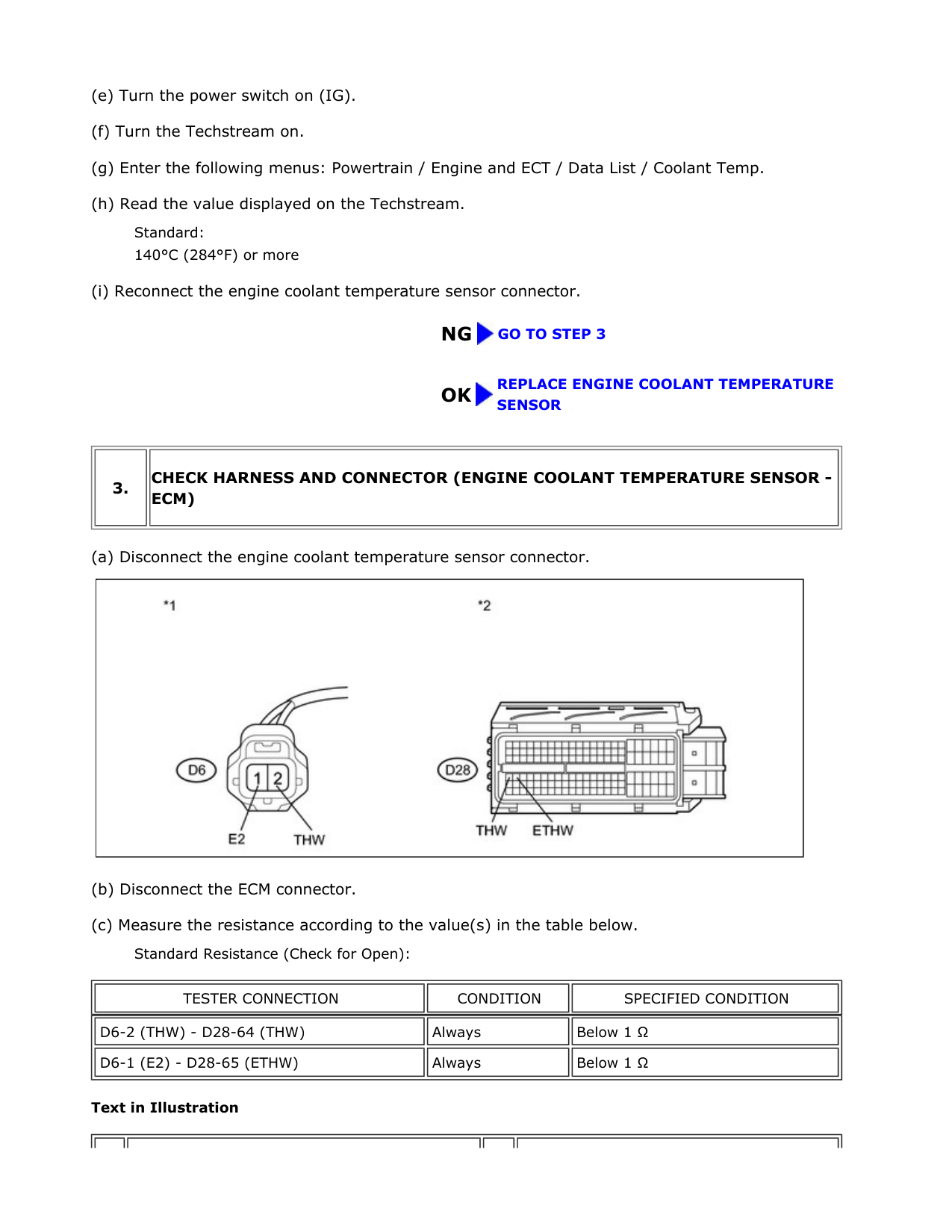
||3.| |---|
|CHECK HARNESS AND CONNECTOR (ENGINE COOLANT TEMPERATURE SENSOR ECM)| |---| | |---|
|| |---|
||TESTER CONNECTION| |---|
|CONDITION| |---|
|SPECIFIED CONDITION| |---| | |---|
||D6-2 (THW) - D28-64 (THW)| |---|
|Always| |---|
|Below 1 Ω| |---|
|D6-1 (E2) - D28-65 (ETHW)| |---|
|Always| |---|
|Below 1 Ω| |---| |
Text in Illustration
*1 Front view of wire harness connector (to Engine Coolant Temperature Sensor)
*2 Front view of wire harness connector (to ECM)
NG
REPAIR OR REPLACE HARNESS OR CONNECTOR (ENGINE COOLANT TEMPERATURE SENSOR - ECM)
OK REPLACE ECM
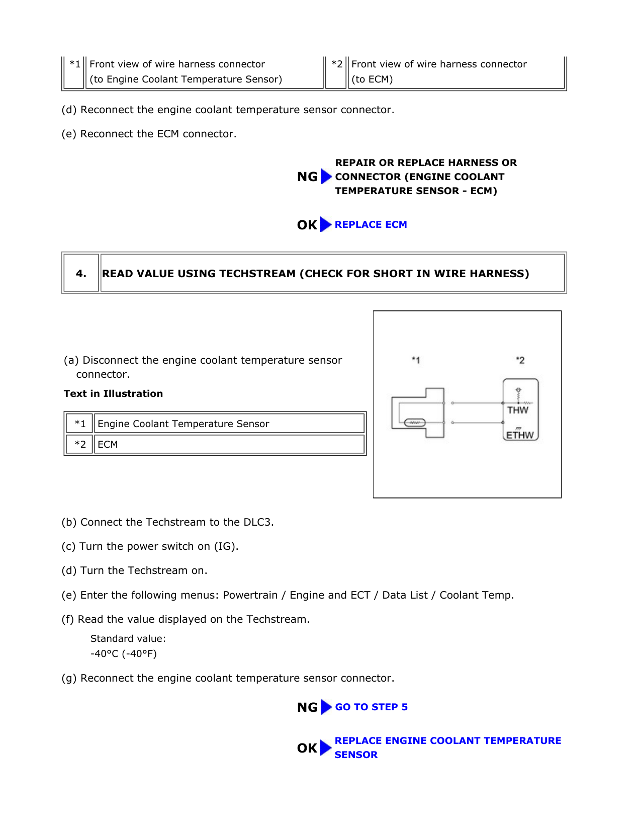
||4.| |---|
|READ VALUE USING TECHSTREAM (CHECK FOR SHORT IN WIRE HARNESS)| |---| | |---|
Text in Illustration
||*1| |---|
|Engine Coolant Temperature Sensor| |---|
|*2| |---|
|ECM| |---| | |---|
|| |---|
Standard value:
-40°C (-40°F)
OK REPLACE ENGINE COOLANT TEMPERATURESENSOR
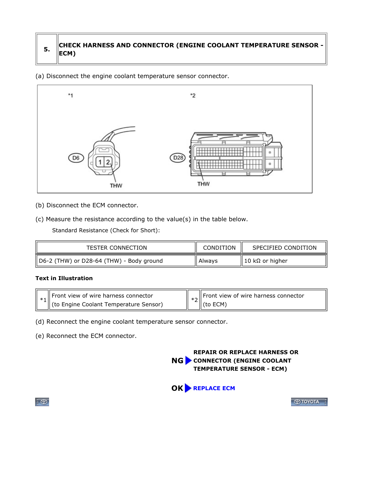
||5.| |---|
|CHECK HARNESS AND CONNECTOR (ENGINE COOLANT TEMPERATURE SENSOR ECM)| |---| | |---|
|| |---|
Text in Illustration
||*1| |---|
|Front view of wire harness connector (to Engine Coolant Temperature Sensor)| |---|
|*2| |---|
|Front view of wire harness connector (to ECM)| |---| | |---|
||TESTER CONNECTION| |---|
|CONDITION| |---|
|SPECIFIED CONDITION| |---| | |---| ||D6-2 (THW) or D28-64 (THW) - Body ground| |---|
|Always| |---|
|10 kΩ or higher| |---| |
NG
REPAIR OR REPLACE HARNESS OR CONNECTOR (ENGINE COOLANT TEMPERATURE SENSOR - ECM)

OK REPLACE ECM
