
Ask AI
— answers from the official manualAnswers from the official manual.
Common questions
Common Questions
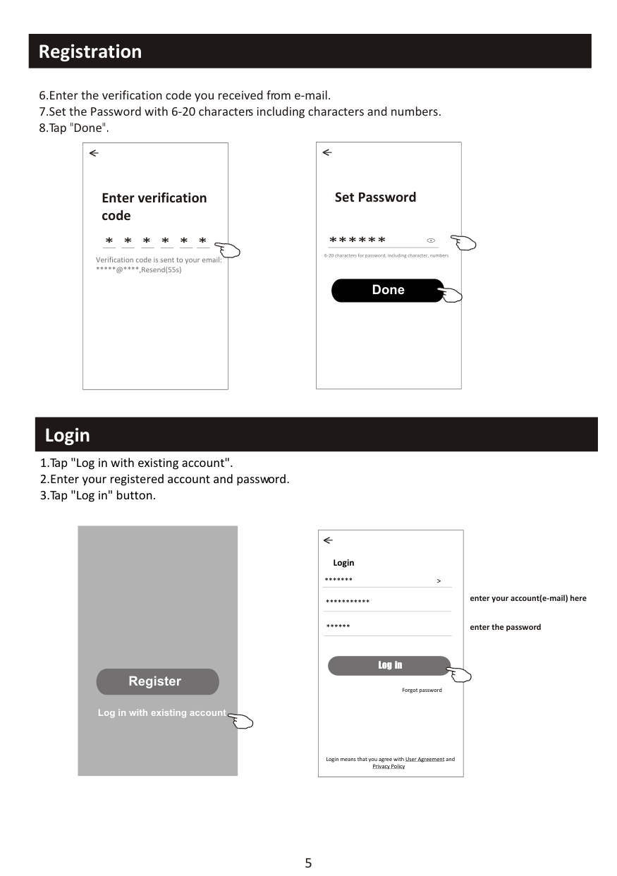
10 totalHow do I replace or clean the air filter?
To clean the air filter, shut down the machine and cut off power for more than 5 minutes. Remove the filter screen by taking out its opposite direction from the unit. Clean it with soapy water and allow it to air dry completely before reinstalling. If you find dust accumulation, clean the filter promptly to maintain efficiency (Page 32).
How do I factory reset my remote control?
Press and hold the ECO button for over 6 seconds on some models until it displays ( ) on the LED. Do this again to deactivate the function, effectively resetting any specific settings (Page 10).
What steps are involved in installing the outdoor unit of my air conditioner?
Start by selecting a suitable installation location according to safety precautions such as ensuring it is not near heat sources or flammable substances, then drill holes and secure expansion bolts. Install rubber blankets for noise reduction if needed before mounting the outdoor unit securely to the brackets with wrenches (Page 26).
What should I do during a defrost cycle?
During defrosting, indoor unit fan stops. Upon completion, it automatically resumes heating operations. This procedure is essential to clean frost from the condenser and recover heat exchange function (Page 9).
How do I activate 8 heating function on my remote control?
Long press the ECO button over 3 seconds; if it displays a specific icon, your unit is now in 8C heating mode and will automatically start when room temperature drops below 8C (Page 10).
What safety measures should I take while disposing of my air conditioner?
Do not dispose as unsorted municipal waste; refrigerants and potential hazardous materials must be collected separately for proper treatment. Follow the guidelines provided in Disposal Instructions section (Page 33).
Full Manual
64 pages
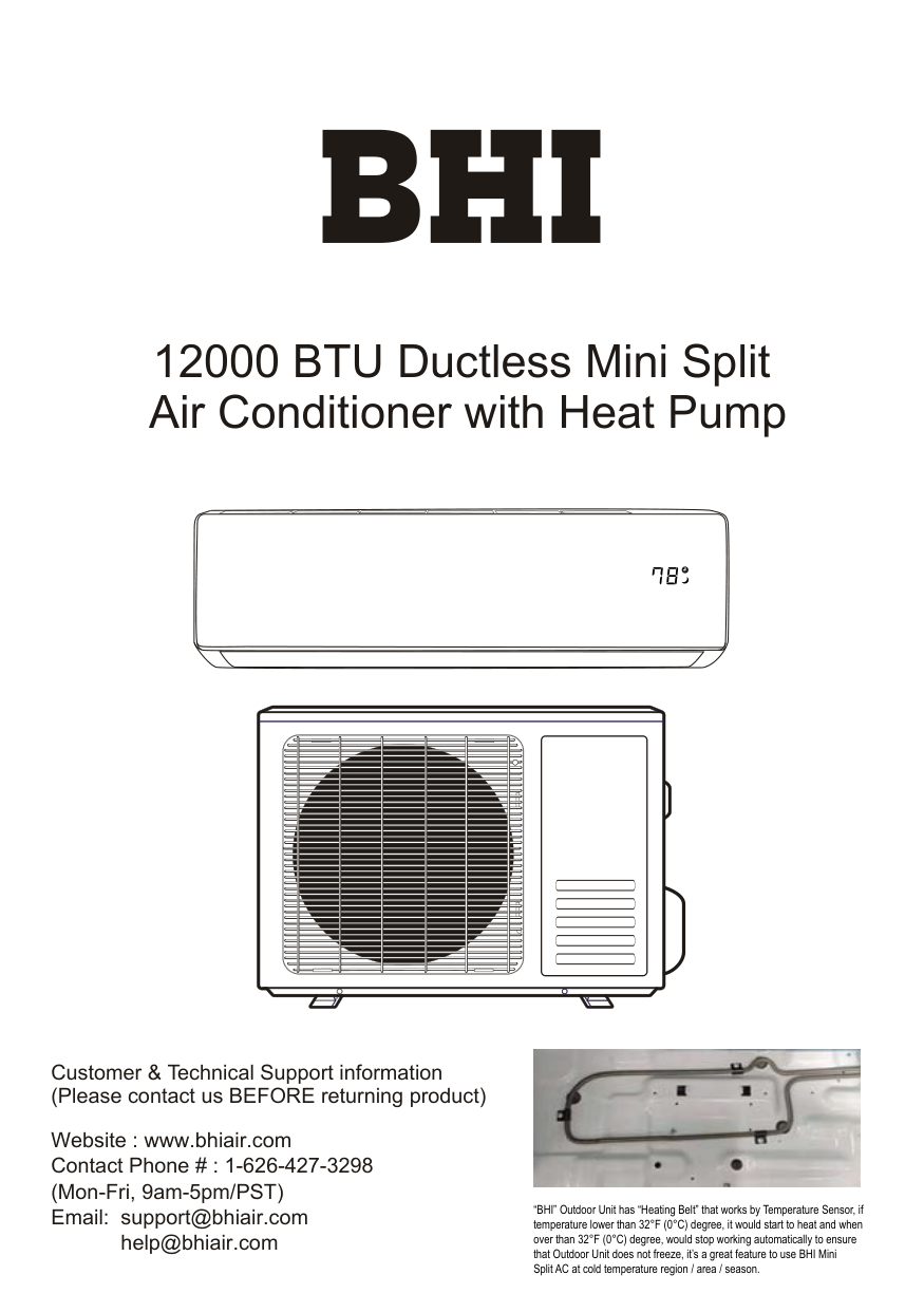
12000 BTU Ductless Mini Split Air Conditioner with Heat Pump
Customer & Technical Support information (Please contact us BEFORE returning product)
Website : www.bhiair.com Contact Phone # : 1-626-427-3298 (Mon-Fri, 9am-5pm/PST) Email: [email protected]

“BHI” Outdoor Unit has “Heating Belt” that works by Temperature Sensor, if temperature lower than 32°F (0°C) degree, it would start to heat and when over than 32°F (0°C) degree, would stop working automatically to ensure that Outdoor Unit does not freeze, it’s a great feature to use BHI Mini Split AC at cold temperature region / area / season.
################# CONTENTS
.....................................................................................................................1
SAFETY PRECAUTIONS NAME OF PARTS REMOTE CONTROL OPERATION INSTRUCTIONS INSTALLATION PRECAUTIONS INDOOR UNIT INSTALLATION OUTDOOR UNIT INSTALLATION TEST OPERATION MAINTENANCE TROUBLESHOOTING
............................................................................................................................4
...........................................................................................................................6
............................................................................................................13
.........................................................................................................14
.........................................................................................................15
.....................................................................................................20
............................................................................................................................23
...............................................................................................................................25
.......................................................................................................................26
forbidden to children. Unforeseeable accidents could happen.

the air conditioner.
another overload protection device.
or power plug clean. Insert the power plug correctly and firmly into the socket, thereby avoiding the risk of electric shock or fire due to insufficient contact.
contact separation in all poles that provide full disconnection under over voltage category III conditions, and these means must be incorporated in the fixed wiring in accordance with the wiring rules.
(alcohol, etc.) Or from pressurized containers (e.g. spray cans).
to prevent any leaks of refrigerant gas from remaining in the environment and creating a danger of fire.
Take the air conditioner at the end of its useful life to a special waste collection center for disposal.
cover every possible condition and situation. As with any electrical household appliance, common sense and caution are therefore always recommended for installation, operation and maintenance.
physical, sensory or mental capabilities or lack of experience and knowledge if they have been given supervision or instruction concerning use of the appliance in a safe way and understand the hazards involved. Children shall not play with the appliance. Cleaning and user maintenance shall not be made by children without supervision.
1
disconnect the appliance from the mains electricity supply before carrying out any cleaning or maintenance.
or power plug clean. Insert the power plug correctly and firmly into the socket, thereby avoiding the risk of electric shock or fire due to insufficient contact.
a spark and cause a fire, etc.
for any other purpose, such as for drying clothes, cooling food, etc.
could cause an excessive accumulation of dust or waste on the inner parts of the device with possible subsequent failures.
check that it is earth in accordance with current legislation and insert a thermos magnetic circuit breaker.
scrap batteries, please discard the batteries as sorted municipal waste at the accessible collection point.
exposition to cold air could be dangerous for your health. Particular care should be taken in the rooms where there are children, old or sick people.
supply and contact the Service Center.
repair could expose the user to the risk of electric shock, etc.
direction must be properly adjusted.
for a long period and before carrying out any cleaning or maintenance.
##################### SAFETY RULES AND PROHIBITIONS
are probably due to a damaged power cord. Specialized technical personnel only must replace a damaged power cord.
openings causes a reduction in the operative efficiency of the conditioner with possible consequent failures or damages.
sources of heat.
sensory or mental capabilities, or lack of experience and knowledge, unless they have been given supervision or instruction concerning use of the appliance by a person responsible for their safety.
plants and animals.
thus causing electrocution.
cord is damaged, it must be replaced by the manufacturer, its service agent or similarly qualified persons in order to avoid a hazard.
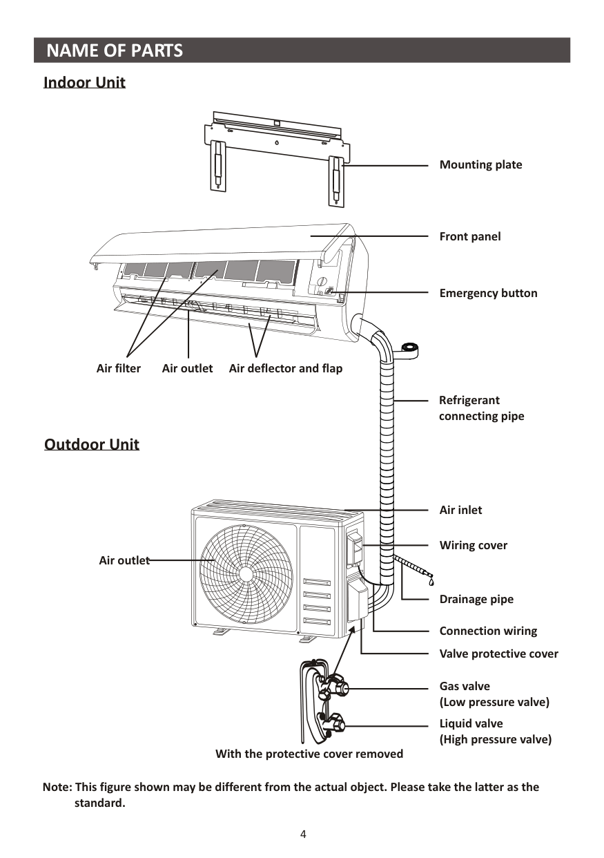
Indoor Unit


Air filter
Air deflector and flapAir outlet
Outdoor Unit
Mounting plate
Front panel
Emergency button
Refrigerant connecting pipe
Air outlet
Air inlet
Wiring cover
With the protective cover removed
Drainage pipe
Connection wiring Valve protective cover
Gas valve (Low pressure valve)
Liquid valve (High pressure valve)
Note: This figure shown may be different from the actual object. Please take the latter as the standard.
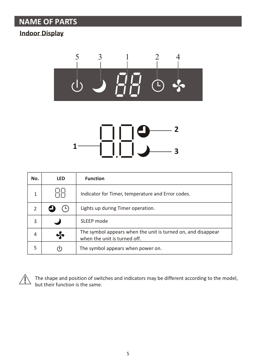
############### Indoor Display
3 42
15
| | |---|
########### 1
| | | | |---|---|---| |1| |Indicator for Timer, temperature and Error codes.| |2| |Lights up during Timer operation.| |3| |SLEEP mode| |4| |The symbol appears when the unit is turned on, and disappear when the unit is turned off.| |5| |The symbol appears when power on.|
The shape and position of switches and indicators may be different according to the model, but their function is the same.
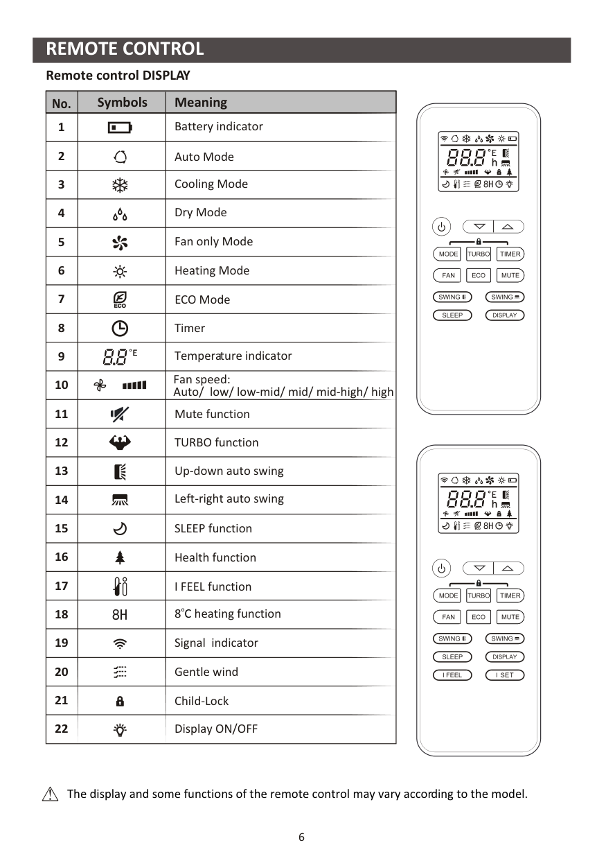
##################### Remote control DISPLAY
|Symbols MeaningNo.| |---| |Cooling Mode Dry Mode Fan only Mode Heating Mode
Fan speed: Auto/ low/ low-mid/ mid/ mid-high/ high
TURBO function
Mute function
Up-down auto swing
Temperature indicator
Left-right auto swing SLEEP function
Timer
Battery indicator Auto Mode
Health function I FEEL function
ECO Mode
8 heating functionoC Signal indicator Gentle wind Child-Lock Display ON/OFF
1
2
3
4
5
6
7
8
9
10
11
12
13
14
15
16
17
18
19
20
21
22
|


The display and some functions of the remote control may vary according to the model.
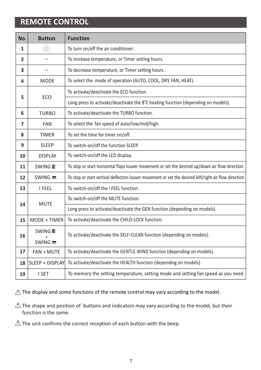
|No.|Button|Function| |---|---|---| |1| |To turn on/off the air conditioner .| |2| |To increase temperature, or Timer setting hours.| |3| |To decrease temperature, or Timer setting hours.| |4|MODE|To select the mode of operation (AUTO, COOL, DRY, FAN, HEAT).| |5|ECO|To activate/deactivate the ECO function.| |5|ECO|Long press to activate/deactivate the 8 heating function (depending on models).oC| |6|TURBO|To activate/deactivate the TURBO function.| |7|FAN|To select the fan speed of auto/low/mid/high.| |8|TIMER|To set the time for timer on/off.| |9|SLEEP|To switch-on/off the function SLEEP.| |10|DISPLAY|To switch-on/off the LED display.| |11|SWING|To stop or start horizontal flaps louver movement or set the desired up/down air flow direction.| |12|SWING|To stop or start vertical deflectors louver movement or set the desired left/right air flow direction.| |13|I FEEL|To switch-on/off the I FEEL function.| |14|MUTE
|To switch-on/off the MUTE function.| |14|MUTE
|Long press to activate/deactivate the GEN function (depending on models).| |15|MODE + TIMER|To activate/deactivate the CHILD-LOCK function.| |16|SWING SWING
+|To activate/deactivate the SELF-CLEAN function (depending on models).| |17|FAN + MUTE|To activate/deactivate the GENTLE WIND function (depending on models).| |18|SLEEP + DISPLAY|To activate/deactivate the HEALTH function (depending on models).| |19|I SET|To memory the setting temperature, setting mode and setting fan speed as you need.|
The display and some functions of the remote control may vary according to the model.
The shape and position of buttons and indicators may vary according to the model, but their function is the same.
The unit confirms the correct reception of each button with the beep.
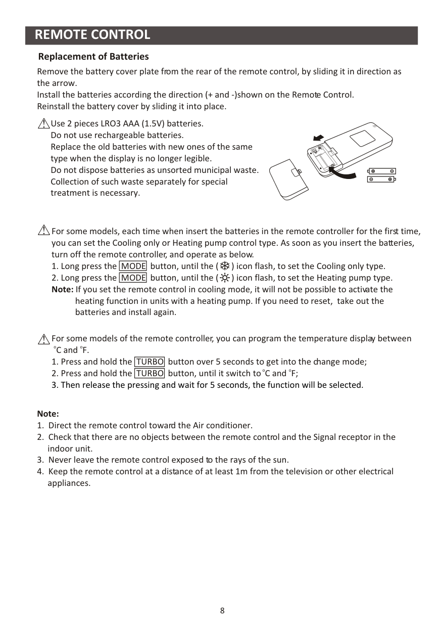
Replacement of Batteries Remove the battery cover plate from the rear of the remote control, by sliding it in direction as the arrow. Install the batteries according the direction (+ and -)shown on the Remote Control. Reinstall the battery cover by sliding it into place.
Use 2 pieces LRO3 AAA (1.5V) batteries. Do not use rechargeable batteries. Replace the old batteries with new ones of the same type when the display is no longer legible. Do not dispose batteries as unsorted municipal waste. Collection of such waste separately for special treatment is necessary.
For some models, each time when insert the batteries in the remote controller for the first time, you can set the Cooling only or Heating pump control type. As soon as you insert the batteries, turn off the remote controller, and operate as below.
heating function in units with a heating pump. If you need to reset, take out the batteries and install again.
For some models of the remote controller, you can program the temperature display between ooC and F.
############################# Note:
##################### COOLING MODE HEATING MODE
The cooling function allows the air conditioner to cool the room and reduce Air humidity at the same time.
The heating function allows the air conditioner to heat the room.
|COOL| |---|
|HEAT| |---|
To activate the heating function (HEAT), press the button until the symbol appears on the
|MODE|
|---|
To activate the cooling function (COOL), press the
display. With the button or set a temperature higher than that of the room.
button until the symbol appears on the display. With the button or set a temperature lower than that of the room.
|MODE| |---|
In HEATING operation, the appliance can automatically activate a defrost cycle, which is essential to clean the frost on the condenser so as to recover its heat exchange function. This procedure usually lasts for 2-10 minutes. During defrosting, indoor unit fan stop operation. After defrosting, it resumes to HEATING mode automatically. (For North American market) If necessary, you can press ECO button 10 times within 8 seconds under heating mode to start the forced defrosting. It will defrost the outdoor ice much faster.
FAN MODE (Not FAN button)
|FAN| |---|
Fan mode, air ventilation only.
until appears on the display.
To set the FAN mode, press
|MODE| |---|
DRY MODE
FAN SPEED function (FAN button)
This function reduces the humidity of the air to make the room more comfortable.
|FAN| |---|
|DRY| |---|
Change the operating fan speed.
Press
button to set the running fan speed, it can be set to AUTO/ MUTE/ LOW/ LOW-MID / MID/ MID-HIGH/ HIGH/ TURBO speed circularly.
|FAN| |---|
until appears in the display. An automatic function of pre-setting is activated.
To set the DRY mode, Press
|MODE| |---|
(Flash)
################## Child-Lock function
##################### AUTO MODE
|AUTO| |---|
|MODE| |---|
and
|TIMER| |---|
button together to active this function, and do it again to deactivate this function.
Automatic mode. To set the AUTO mode, press
until
|MODE| |---|
appears on the display. In AUTO mode the run mode will be set automatically according to the room temperature.
##################### TIMER function ---- TIMER ON SWING function
To automatic switch on the appliance.
|SWING| |---|
|SWING| |---|
|TIMER| |---|
When the unit is switch-off, you can set the TIMER ON. To set the time of automatic switch-on as below:
|SWING| |---|
|TIMER| |---|
button first time to set the switch-on, and will appear on the remote display and flashes.
|TIMER| |---|
button second time to confirm.
|SWING| |---|
button. And set the needed fan speed, by press
|MODE| |---|
button. And press or to set the needed operation temperature.
|FAN| |---|
CANCEL it by press
button.
|TIMER| |---|
This adjustment must be done while the appliance is switched off.
TIMER function ---- TIMER OFF
Never position Flaps manually, the delicate mechanism might seriously damaged!
To automatic switch off the appliance.
|TIMER| |---|
Never put fingers, sticks or other objects into the air inlet or outlet vents. Such accidental contact with live parts might cause unforeseeable damage or injury.
When the unit is switch-on, you can set the TIMER OFF. To set the time of automatic switch-off, as below:
|TIMER| |---|
button at first time to set the
switch-off. Press or to set the needed timer.
TURBO function
|TURBO| |---|
button at the second time to confirm.
|TIMER| |---|
To activate turbo function, press the button, and will appear on the display. Press again to cancel this function. In COOL/ HEAT mode, when you select TURBO feature, the appliance will turn to quick COOL or quick HEAT mode, and operate the highest fan speed to blow strong airflow.
|TURBO| |---|
CANCEL it by press
button.
|TIMER| |---|
Note: All programming should be operated within 5 seconds, otherwise the setting will be cancelled.
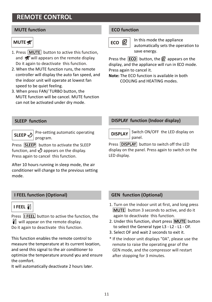
MUTE function ECO function
In this mode the appliance automatically sets the operation to save energy.
|MUTE| |---|
|ECO| |---|
|MUTE| |---|
button to active this function, and will appears on the remote display. Do it again to deactivate this function.
button, the appears on the display, and the appliance will run in ECO mode. Press again to cancel it. Note: The ECO function is available in both COOLING and HEATING modes.
Press the
|ECO| |---|
SLEEP function
Pre-setting automatic operating program.
|SLEEP| |---|
button to activate the SLEEP function, and appears on the display. Press again to cancel this function.
Press
|SLEEP| |---|
After 10 hours running in sleep mode, the air conditioner will change to the previous setting mode.
DISPLAY function (Indoor display)
Switch ON/OFF the LED display on panel.
|DISPLAY| |---|
button to switch off the LED display on the panel. Press again to switch on the LED display.
Press
|DISPLAY| |---|
##################### I FEEL function (Optional)
|I FEEL| |---|
Press
button to active the function, the will appear on the remote display.
|I FEEL| |---|
Do it again to deactivate this function.
This function enables the remote control to measure the temperature at its current location, and send this signal to the air conditioner to optimize the temperature around you and ensure the comfort. It will automatically deactivate 2 hours later.
##################### GEN function (Optional)
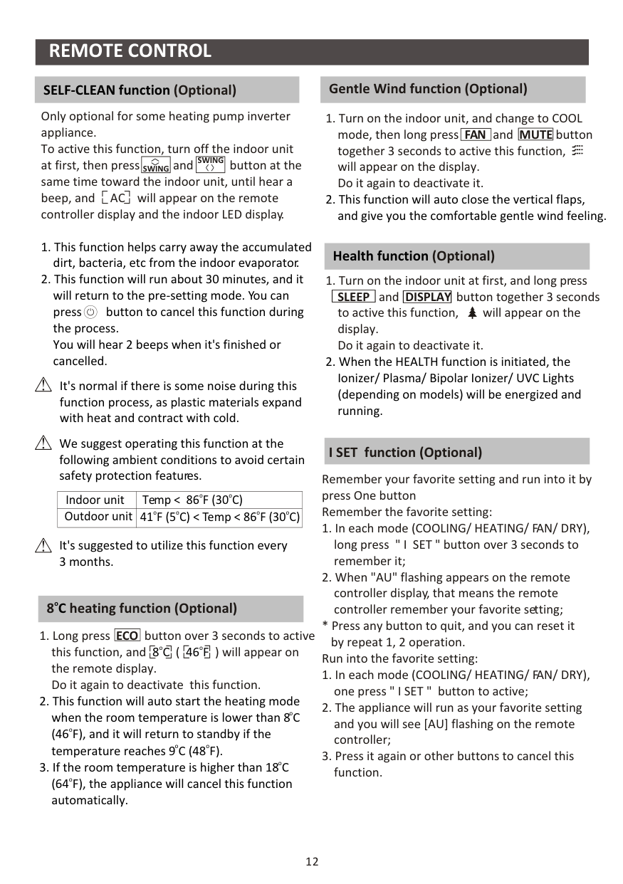
##################### SELF-CLEAN function (Optional) Gentle Wind function (Optional)
Only optional for some heating pump inverter appliance. To active this function, turn off the indoor unit at first, then press and button at the same time toward the indoor unit, until hear a beep, and AC will appear on the remote controller display and the indoor LED display.
|SWING| |---|
|SWING| |---|
##################### Health function (Optional)
It's normal if there is some noise during this function process, as plastic materials expand with heat and contract with cold.
We suggest operating this function at the following ambient conditions to avoid certain safety protection features.
##################### I SET function (Optional)
Remember your favorite setting and run into it by press One button Remember the favorite setting:
|Indoor unit|ooTemp < 86 F (30 C)| |---|---| |Outdoor unit|oo o o41 F (5 C) < Temp < 86 F (30 C)|
It's suggested to utilize this function every 3 months.
##################### 8 heating function (Optional)oC
|ECO| |---|
button over 3 seconds to active this function, and ( ) will appear on the remote display. Do it again to deactivate this function.
oo8C 46F
by repeat 1, 2 operation. Run into the favorite setting:
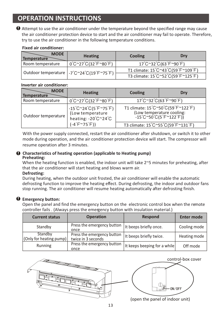
########## OPERATION INSTRUCTIONS
Attempt to use the air conditioner under the temperature beyond the specified range may cause the air conditioner protection device to start and the air conditioner may fail to operate. Therefore, try to use the air conditioner in the following temperature conditions.
Fixed air conditioner:
|Temperature
MODE|Heating|Cooling|Dry| |---|---|---|---| |Room temperature|0 ~27 (32 ~80 )
|17 32 (63 ~90 )~
|17 32 (63 ~90 )~
| |Outdoor temperature|-7 ~24 (19 ~75 )|T1 climate: 15 (59 ~109 )~43
|T1 climate: 15 (59 ~109 )~43
| |Outdoor temperature|-7 ~24 (19 ~75 )|T3 climate: 15 (59 ~125 )~52
|T3 climate: 15 (59 ~125 )~52
|
############################ Inverter air conditioner:
|Temperature
MODE|Heating|Cooling|Dry| |---|---|---|---| |Room temperature|0 ~27 (32 ~80 )
|17 32 (63 ~90 )~
|17 32 (63 ~90 )~
| |Outdoor temperature|-15 ~24 (5 ~75 )
(Low temperature heating: -20 ~24 (-4 ~75 ))
|T1 climate: ~50 (Low temperature cooling: ~50
15 (59 ~122 )
-15 (5 ~122 ))|T1 climate: ~50 (Low temperature cooling: ~50
15 (59 ~122 )
-15 (5 ~122 ))| |Outdoor temperature|-15 ~24 (5 ~75 )
(Low temperature heating: -20 ~24 (-4 ~75 ))
|T3 climate: 15 (59 ~131 )~55
|T3 climate: 15 (59 ~131 )~55
|
With the power supply connected, restart the air conditioner after shutdown, or switch it to other mode during operation, and the air conditioner protection device will start. The compressor will resume operation after 3 minutes.
Characteristics of heating operation (applicable to Heating pump)
Preheating: When the heating function is enabled, the indoor unit will take 2~5 minutes for preheating, after that the air conditioner will start heating and blows warm air. Defrosting: During heating, when the outdoor unit frosted, the air conditioner will enable the automatic defrosting function to improve the heating effect. During defrosting, the indoor and outdoor fans stop running. The air conditioner will resume heating automatically after defrosting finish.
Emergency button: Open the panel and find the emergency button on the electronic control box when the remote controller fails . (Always press the emergency button with insulation material.)
|Current status|Operation|Respond|Enter mode| |---|---|---|---| |Standby|Press the emergency button once|It beeps briefly once.|Cooling mode| |Standby (Only for heating pump)|Press the emergency button twice in 3 seconds|It beeps briefly twice.|Heating mode| |Running|Press the emergency button once|It keeps beeping for a while|Off mode|
control-box cover
(open the panel of indoor unit)
13
| | | | | | |---|---|---|---|---| | | | | | | | | | | | | | | | | | | | | | | | | | | | | | | | | | | | |
| | | | | | |---|---|---|---|---| | | | | | | | | | | | | | | | | | |
| | | | | | | | | | | |
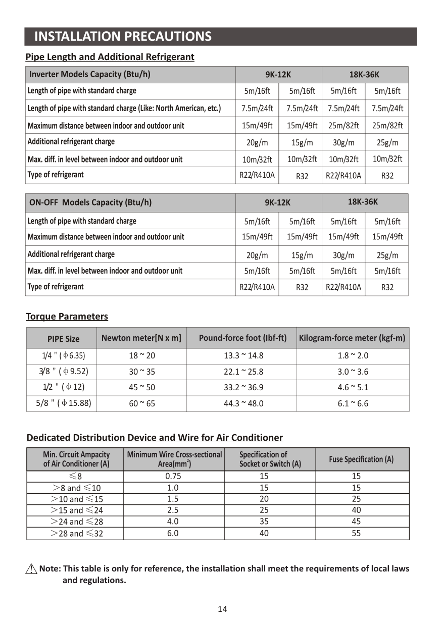
######################## Torque Parameters
|PIPE Size|Newton meter[N x m]|Pound-force foot (Ibf-ft)|Kilogram-force meter (kgf-m)| |---|---|---|---| |1/4 ( 6.35)|18 ~ 20|13.3 ~ 14.8|1.8 ~ 2.0| |3/8 ( 9.52)|30 ~ 35|22.1 ~ 25.8|3.0 ~ 3.6| |1/2 ( 12)|45 ~ 50|33.2 ~ 36.9|4.6 ~ 5.1| |5/8 ( 15.88)|60 ~ 65|44.3 ~ 48.0|6.1 ~ 6.6|
| | | | |---|---|---| | | | | | | | | | | | | | | | | | | | | | | | |
Note: This table is only for reference, the installation shall meet the requirements of local laws and regulations.
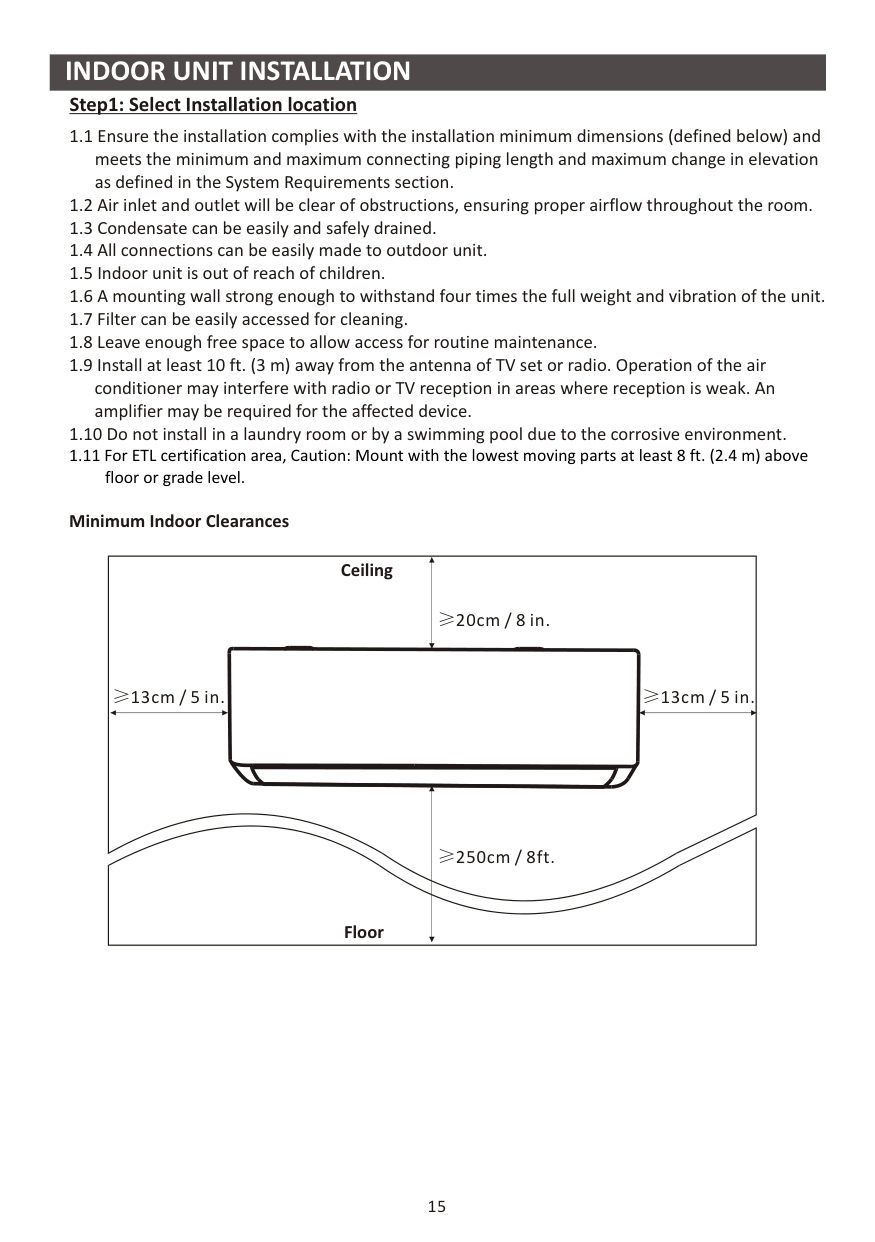
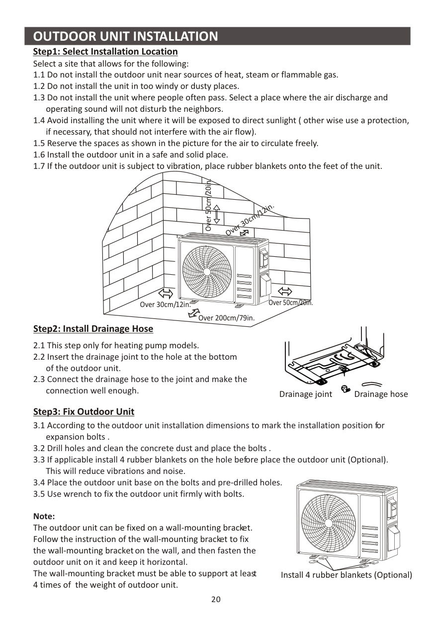
################### Step1: Select Installation location
Minimum Indoor Clearances
Ceiling
20cm / 8 in.
13cm / 5 in.
13cm / 5 in.
Floor
250cm / 8ft.
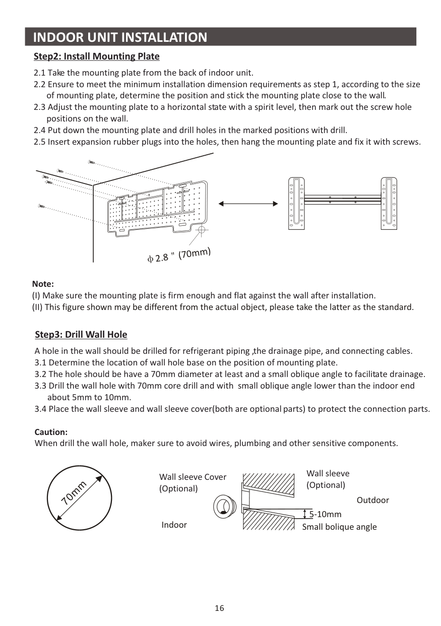
################### Step2: Install Mounting Plate
| | | | |---|---|---| | | | | | | | | | | | |
########################## 2.8 (70mm)
############################ Note:
######################## Step3: Drill Wall Hole
A hole in the wall should be drilled for refrigerant piping ,the drainage pipe, and connecting cables.
Caution: When drill the wall hole, maker sure to avoid wires, plumbing and other sensitive components.
m
m
70
Wall sleeve (Optional)
Wall sleeve Cover (Optional)
Outdoor
5-10mm
Indoor Small bolique angle
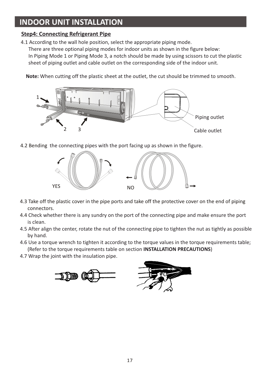
Note: When cutting off the plastic sheet at the outlet, the cut should be trimmed to smooth.


32
1
Piping outlet Cable outlet


NOYES
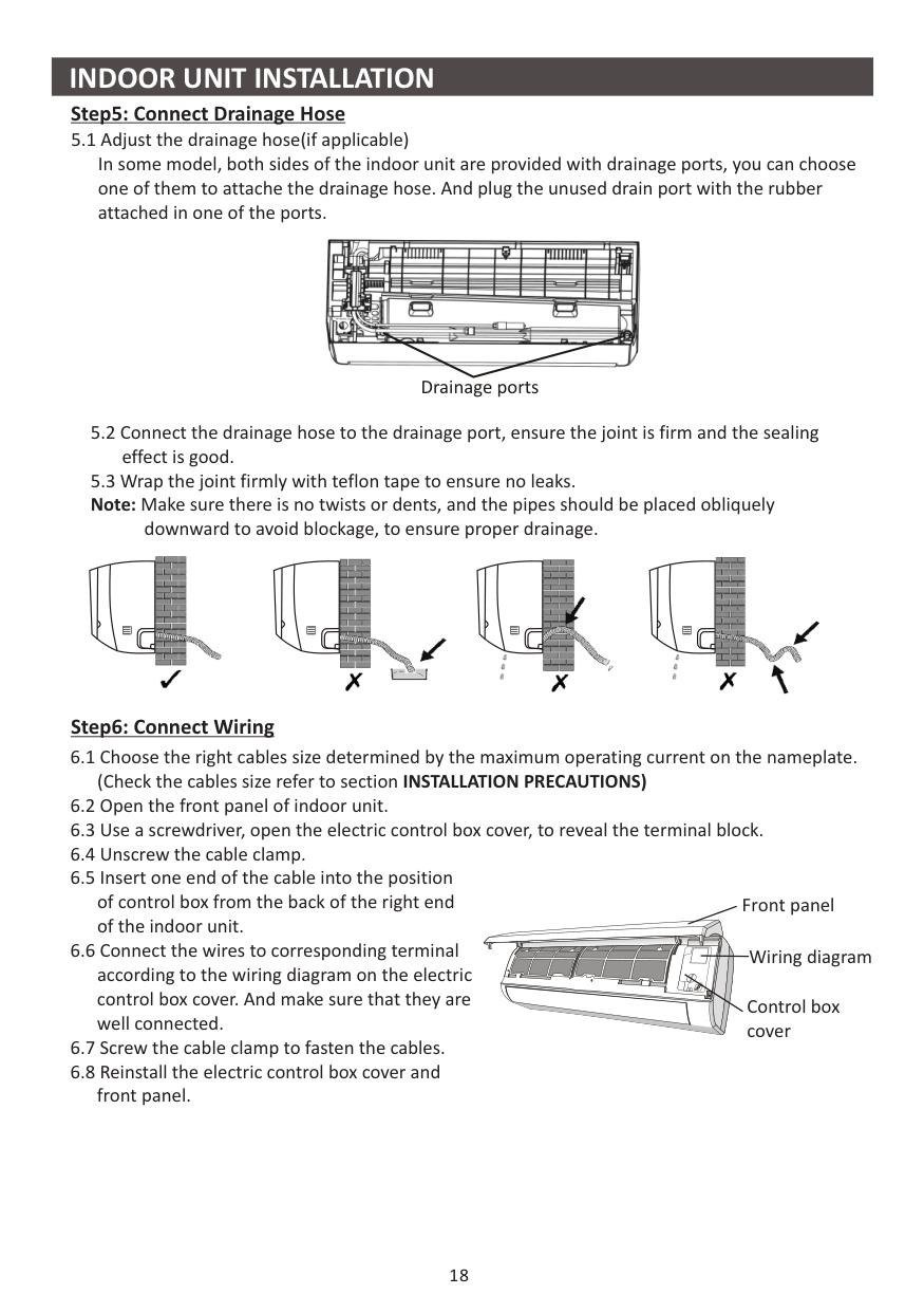
Step5: Connect Drainage Hose
downward to avoid blockage, to ensure proper drainage.
Step6: Connect Wiring

Drainage ports


Front panel


Wiring diagram


Control box cover


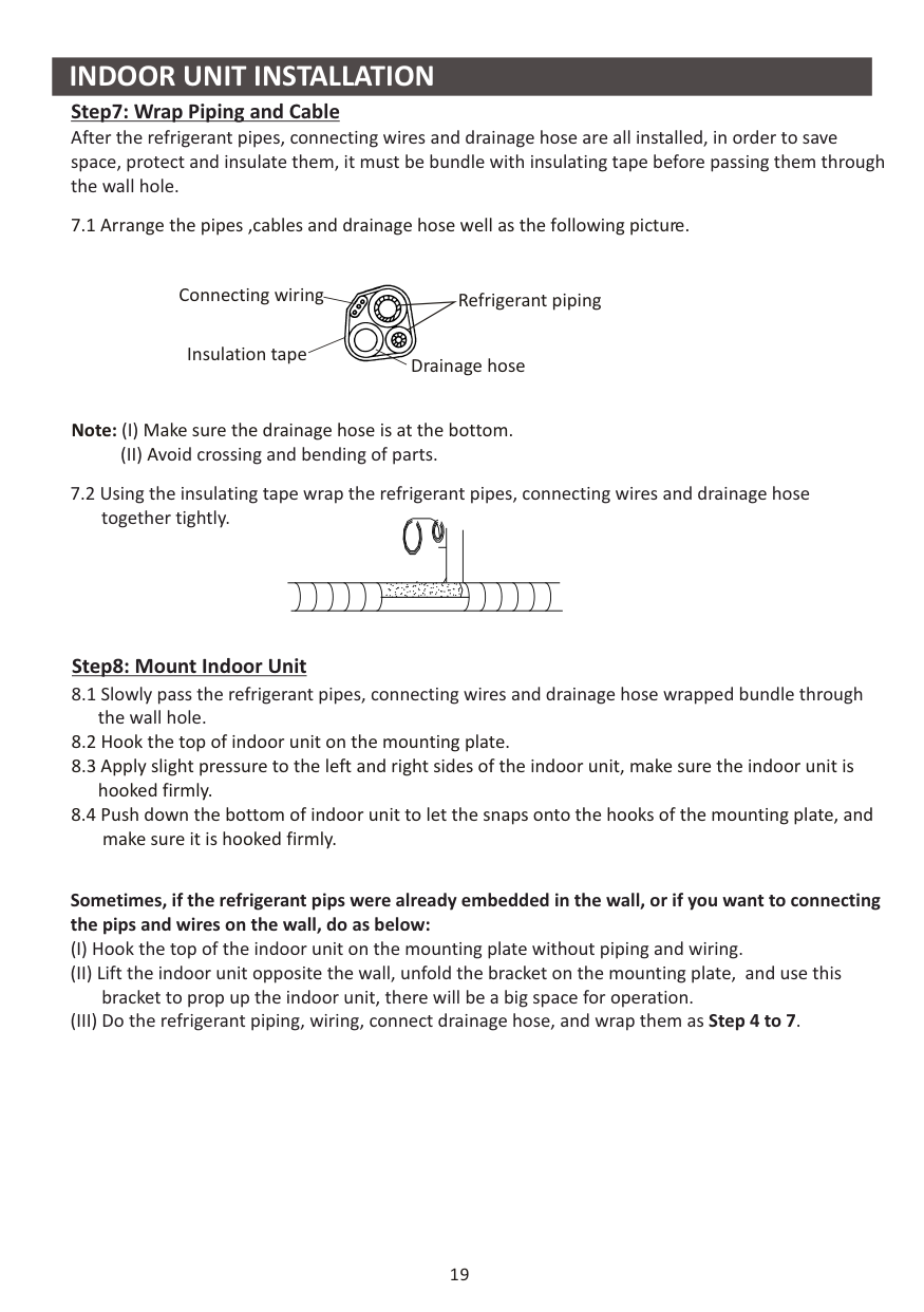
################### Step7: Wrap Piping and Cable
After the refrigerant pipes, connecting wires and drainage hose are all installed, in order to save space, protect and insulate them, it must be bundle with insulating tape before passing them through the wall hole.
7.1 Arrange the pipes ,cables and drainage hose well as the following picture.
Connecting wiring Refrigerant piping
Insulation tape
Drainage hose
Note: Make sure the drainage hose is at the bottom.
A
Step8: Mount Indoor Unit
Sometimes, if the refrigerant pips were already embedded in the wall, or if you want to connecting the pips and wires on the wall, do as below:
Over 50cm/20in.
ver 30cm/12in.
O
Over 30cm/12in. Over 50cm/20in.
Over 200cm/79in.
The outdoor unit can be fixed on a wall-mounting bracket. Follow the instruction of the wall-mounting bracket to
wall-mounting bracket wall-mounting bracket must be able to support at least
4 times of the weight of outdoor unit.
outdoor unit installation dimensions to mark the installation position for expansion bolts .
Drainage joint Drainage hose
fix the on the wall, and then fasten the outdoor unit on it and keep it horizontal. The
Install 4 rubber blankets (Optional)
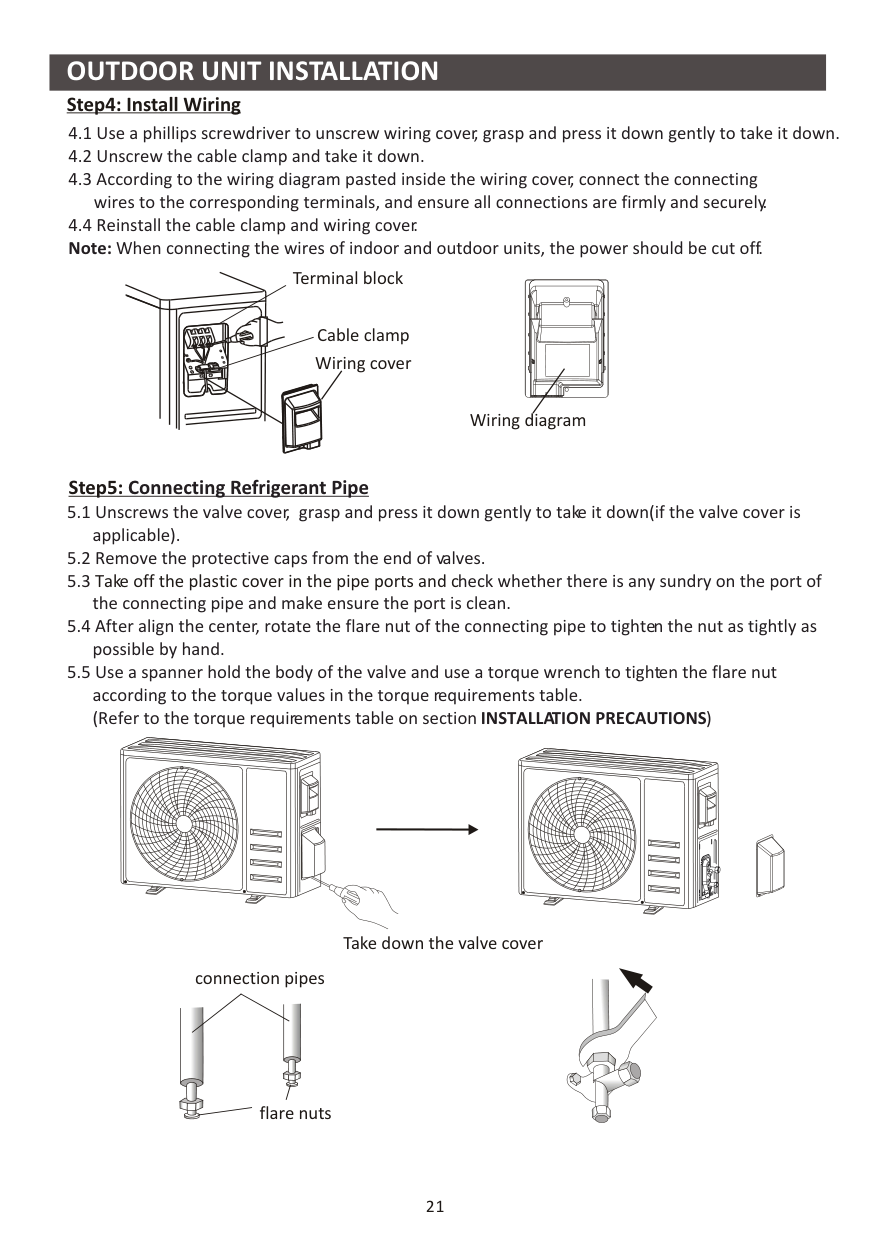
Terminal block
Cable clamp Wiring cover
Wiring diagram
Take off the plastic cover in the pipe ports and c
connection pipes


flare nuts


Take down the valve cover


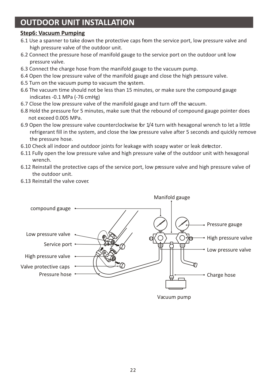
################### Step6: Vacuum Pumping
indicates -0.1 MPa (-76 cmHg)
Turn on the vacuum pump to vacuum the system.
Manifold gauge
compound gauge
Pressure gauge High pressure valve
Low pressure valve
Service port
Low pressure valve
High pressure valve
Valve protective caps Pressure hose
Charge hose
Vacuum pump
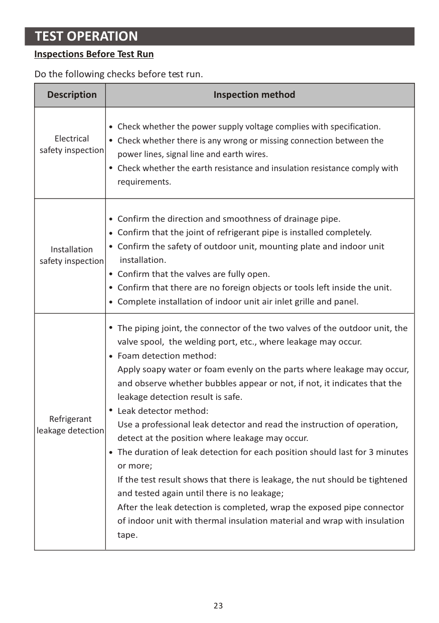
##################### Inspections Before Test Run
Do the following checks before test run.
|Description|Inspection method| |---|---| |Electrical safety inspection|Check whether the power supply voltage complies with specification. Check whether there is any wrong or missing connection between the power lines, signal line and earth wires. Check whether the earth resistance and insulation resistance comply with requirements.| |Installation safety inspection|Confirm the direction and smoothness of drainage pipe. Confirm that the joint of refrigerant pipe is installed completely. Confirm the safety of outdoor unit, mounting plate and indoor unit
installation. Confirm that the valves are fully open. Confirm that there are no foreign objects or tools left inside the unit. Complete installation of indoor unit air inlet grille and panel.| |Refrigerant leakage detection|The piping joint, the connector of the two valves of the outdoor unit, the valve spool, the welding port, etc., where leakage may occur. Foam detection method: Apply soapy water or foam evenly on the parts where leakage may occur, and observe whether bubbles appear or not, if not, it indicates that the leakage detection result is safe. Leak detector method: Use a professional leak detector and read the instruction of operation, detect at the position where leakage may occur. The duration of leak detection for each position should last for 3 minutes or more; If the test result shows that there is leakage, the nut should be tightened and tested again until there is no leakage; After the leak detection is completed, wrap the exposed pipe connector of indoor unit with thermal insulation material and wrap with insulation tape.
|
################### Test Run Instruction
############################# Note:
If the ambient temperature is excess the range refer to section OPERATION INSTRUCTIONS, and it can not run COOL or HEAT mode, lift the front panel and refer to the emergency button operation to run the COOL and HEAT mode.
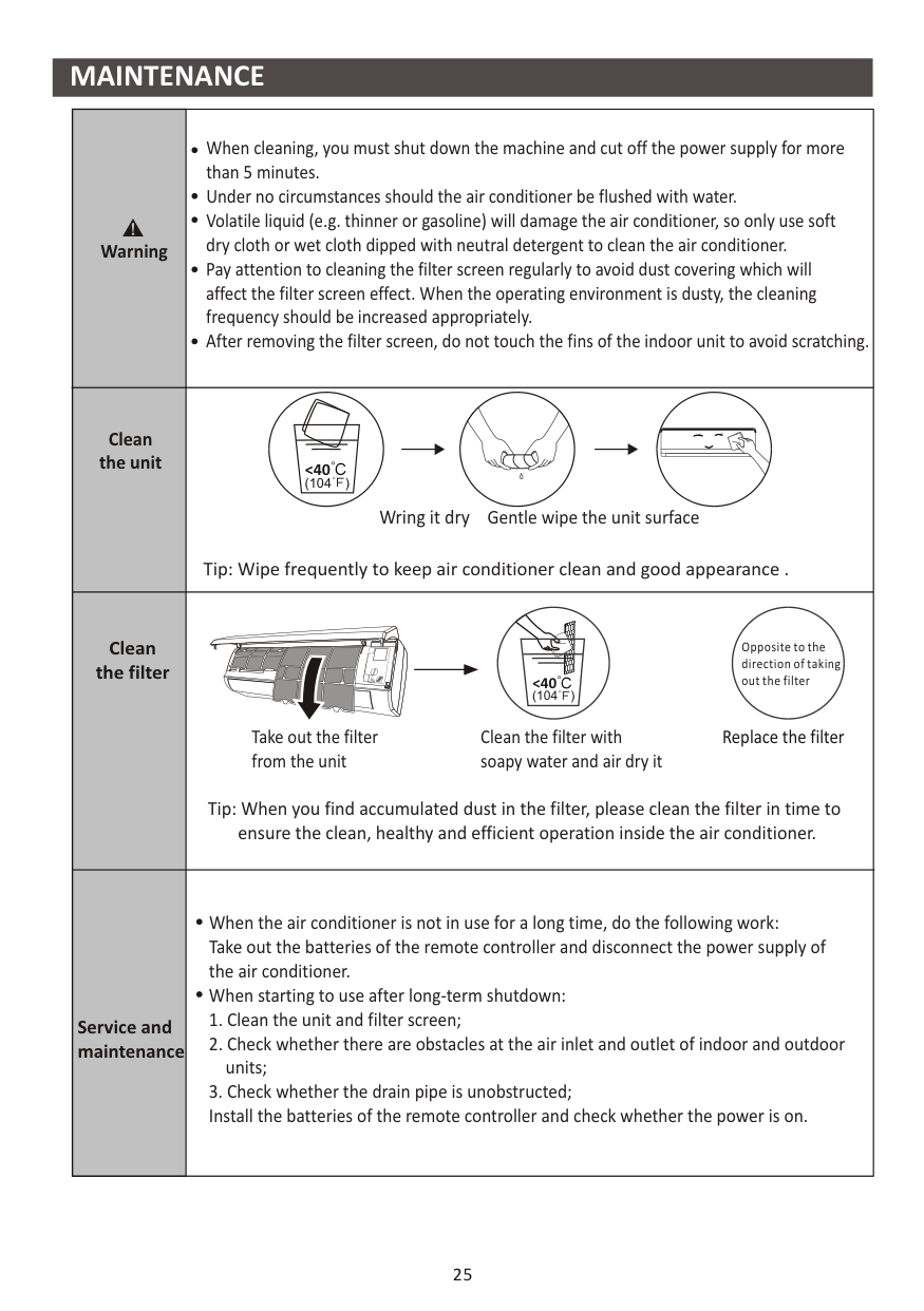
########## MAINTENANCE
|Warning|When cleaning, you must shut down the machine and cut off the power supply for more than 5 minutes. Under no circumstances should the air conditioner be flushed with water. Volatile liquid (e.g. thinner or gasoline) will damage the air conditioner, so only use soft dry cloth or wet cloth dipped with neutral detergent to clean the air conditioner. Pay attention to cleaning the filter screen regularly to avoid dust covering which will affect the filter screen effect. When the operating environment is dusty, the cleaning frequency should be increased appropriately. After removing the filter screen, do not touch the fins of the indoor unit to avoid scratching.
| |---|---| |Clean the unit|Tip: Wipe frequently to keep air conditioner clean and good appearance .
Wring it dry Gentle wipe the unit surface
<40 (104 )
| |Clean the filter|

Opposite to the direction of taking out the filter
Take out the filter from the unit
Clean the filter with soapy water and air dry it
Replace the filter
Tip: When you find accumulated dust in the filter, please clean the filter in time to ensure the clean, healthy and efficient operation inside the air conditioner.
<40 (104 )
| |Service and maintenance|When the air conditioner is not in use for a long time, do the following work: Take out the batteries of the remote controller and disconnect the power supply of the air conditioner. When starting to use after long-term shutdown:
1. Clean the unit and filter screen;
2. Check whether there are obstacles at the air inlet and outlet of indoor and outdoor units;
3. Check whether the drain pipe is unobstructed; Install the batteries of the remote controller and check whether the power is on.
|
|26
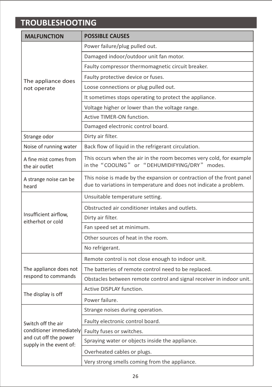
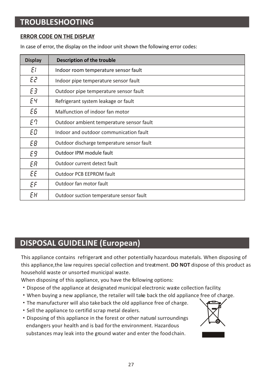
TROUBLESHOOTING
|MALFUNCTION|POSSIBLE CAUSES| |---|---| |The appliance does not operate|Power failure/plug pulled out.| |The appliance does not operate|Damaged indoor/outdoor unit fan motor.| |The appliance does not operate|Faulty compressor thermomagnetic circuit breaker.| |The appliance does not operate|Faulty protective device or fuses.| |The appliance does not operate|Loose connections or plug pulled out.| |The appliance does not operate|It sometimes stops operating to protect the appliance.| |The appliance does not operate|Voltage higher or lower than the voltage range.| |The appliance does not operate|Active TIMER-ON function.| |The appliance does not operate|Damaged electronic control board.| |Strange odor|Dirty air filter.| |Noise of running water|Back flow of liquid in the refrigerant circulation.| |A fine mist comes from the air outlet|This occurs when the air in the room becomes very cold, for example in the COOLING or DEHUMIDIFYING/DRY modes.| |A strange noise can be heard|This noise is made by the expansion or contraction of the front panel due to variations in temperature and does not indicate a problem.| |Insufficient airflow, eitherhot or cold|Unsuitable temperature setting.| |Insufficient airflow, eitherhot or cold|Obstructed air conditioner intakes and outlets.| |Insufficient airflow, eitherhot or cold|Dirty air filter.| |Insufficient airflow, eitherhot or cold|Fan speed set at minimum.| |Insufficient airflow, eitherhot or cold|Other sources of heat in the room.| |Insufficient airflow, eitherhot or cold|No refrigerant.| |The appliance does not respond to commands|Remote control is not close enough to indoor unit.| |The appliance does not respond to commands|The batteries of remote control need to be replaced.| |The appliance does not respond to commands|Obstacles between remote control and signal receiver in indoor unit.| |The display is off|Active DISPLAY function.| |The display is off|Power failure.| |Switch off the air conditioner immediately and cut off the power supply in the event of:|Strange noises during operation.| |Switch off the air conditioner immediately and cut off the power supply in the event of:|Faulty electronic control board.| |Switch off the air conditioner immediately and cut off the power supply in the event of:|Faulty fuses or switches.| |Switch off the air conditioner immediately and cut off the power supply in the event of:|Spraying water or objects inside the appliance.| |Switch off the air conditioner immediately and cut off the power supply in the event of:|Overheated cables or plugs.| |Switch off the air conditioner immediately and cut off the power supply in the event of:|Very strong smells coming from the appliance.| | |---|
########## TROUBLESHOOTING
####################### ERROR CODE ON THE DISPLAY In case of error, the display on the indoor unit shown the following error codes:
|Display|Description of the trouble| |---|---| | |Indoor room temperature sensor fault| | |Indoor pipe temperature sensor fault| | |Outdoor pipe temperature sensor fault| | |Refrigerant system leakage or fault| | |Malfunction of indoor fan motor| | |Outdoor ambient temperature sensor fault| | |Indoor and outdoor communication fault| | |Outdoor discharge temperature sensor fault| | |Outdoor IPM module fault| | |Outdoor current detect fault| | |Outdoor PCB EEPROM fault| | |Outdoor fan motor fault| | |Outdoor suction temperature sensor fault|
########## DISPOSAL GUIDELINE (European)
This appliance contains refrigerant and other potentially hazardous materials. When disposing of this appliance,the law requires special collection and treatment. DO NOT dispose of this product as household waste or unsorted municipal waste. When disposing of this appliance, you have the following options:
Dispose of the appliance at designated municipal electronic waste collection facility. When buying a new appliance, the retailer will take back the old appliance free of charge. The manufacturer will also take back the old appliance free of charge. Sell the appliance to certifid scrap metal dealers. Disposing of this appliance in the forest or other natural surroundings endangers your health and is bad for the environment. Hazardous substances may leak into the ground water and enter the food chain.
27


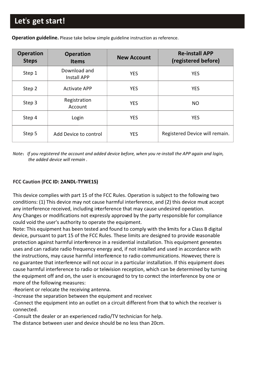
########## Let's get start!
Operation guideline. Please take below simple guideline instruction as reference.
|Operation Steps|Operation Items|New Account|Re-install APP (registered before)| |---|---|---|---| |Step 1|Download and Install APP|YES|YES| |Step 2|Activate APP|YES|YES| |Step 3|Registration Account|YES|NO| |Step 4|Login|YES|YES| |Step 5|Add Device to control|YES|Registered Device will remain.|
Note If you registered the account and added device before, when you re-install the APP again and login, the added device will remain .
############################# FCC Caution (FCC ID: 2ANDL-TYWE1S)
This device complies with part 15 of the FCC Rules. Operation is subject to the following two conditions: (1) This device may not cause harmful interference, and (2) this device must accept any interference received, including interference that may cause undesired operation. Any Changes or modifications not expressly approved by the party responsible for compliance could void the user's authority to operate the equipment. Note: This equipment has been tested and found to comply with the limits for a Class B digital device, pursuant to part 15 of the FCC Rules. These limits are designed to provide reasonable protection against harmful interference in a residential installation. This equipment generates uses and can radiate radio frequency energy and, if not installed and used in accordance with the instructions, may cause harmful interference to radio communications. However, there is no guarantee that interference will not occur in a particular installation. If this equipment does cause harmful interference to radio or television reception, which can be determined by turning the equipment off and on, the user is encouraged to try to correct the interference by one or more of the following measures:
###### CONTENTS
Wi-Fi Module specification and basic information..............................................1 Download and Install the App.............................................................................2 Activate APP.........................................................................................................3 Registration.........................................................................................................4 Login....................................................................................................................6 Add device........................................................................................................8 Air conditioner control.......................................................................................10 Account management........................................................................................28 Trouble Shooting...............................................................................30
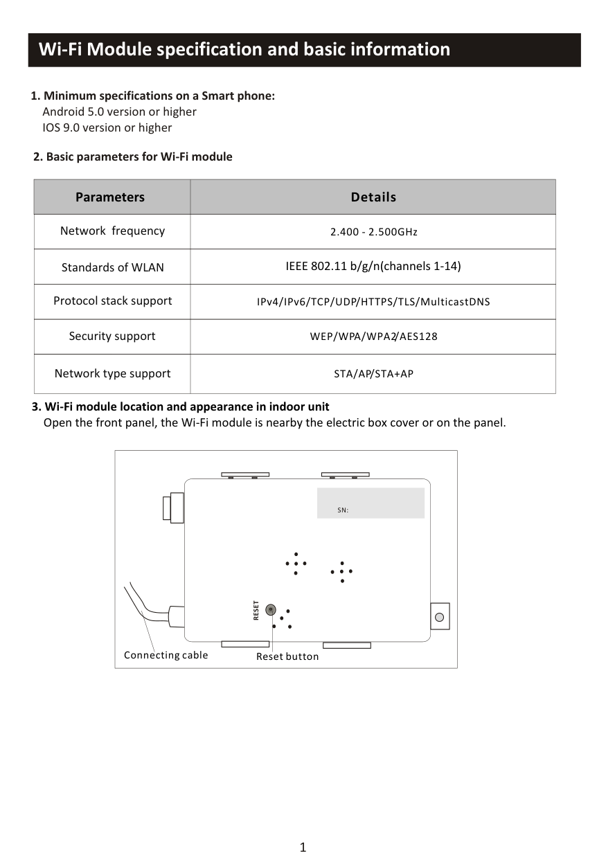
Wi-Fi Module specification and basic information
############################## 1. Minimum specifications on a Smart phone:Android 5.0 version or higherIOS 9.0 version or higher
############################# 2. Basic parameters for Wi-Fi module
|Parameters|Details| |---|---| |Network frequency|2.400 - 2.500GHz| |Standards of WLAN|IEEE 802.11 b/g/n(channels 1-14)| |Protocol stack support|IPv4/IPv6/TCP/UDP/HTTPS/TLS/MulticastDNS| |Security support|WEP/WPA/WPA2/AES128| |Network type support|STA/AP/STA+AP|
Open the front panel, the Wi-Fi module is nearby the electric box cover or on the panel.
|RESET
|SN:| |---|
Reset buttonConnecting cable
| |---|
########## Download and Install the App

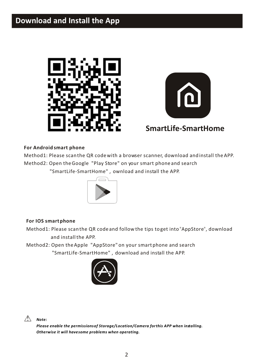
######### SmartLife-SmartHome
For Android smart phone Method1: Please scan the QR code with a browser scanner, download and install the APP. Method2: Open the Google "Play Store" on your smart phone and search
"SmartLife-SmartHome" , ownload and install the APP.
For IOS smart phone Method1: Please scan the QR code and follow the tips to get into"AppStore", download
and install the APP. Method2: Open the Apple "AppStore" on your smart phone and search "SmartLife-SmartHome" , download and install the APP.
Note: Please enable the permissions of Storage/Location/Camera for this APP when installing. Otherwise it will have some problems when operating.
################ The first time the app is used, it will need activating.
Activate APP
SmartLife-SmartHome
then enter the activate code and tap "CONFIRM".
Activate QR code and activation code

Scan the activation QR code from instructions or device
Scan
######## OR
|BHI| |---|
Note Without the QR code or activation code,
you can't active the APP and using it, please keep them safe.
or Enter Activation Code
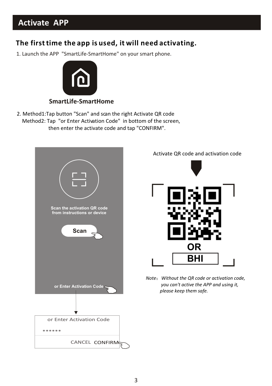
|or Enter Activation Code
CANCEL CONFIRM
**| |---|
Privacy Policy
we pay high attention to the privacy of personal information. To fully present how we collect and use your personal information, we revised the Privacy Policy in detail in compliance with the latest laws and regulations. By clicking Agree, you agree that you have fully read, understood and accepted all the content of the revised Privacy policy. Please take your time to read the Privacy Policy. If you have any question, please contact us at any time.
############################### Register
Log in with existing account
Privacy Policy
Disagree Agree
Search the country or slide the screen up/down to find and choose the Country.
<
<
Country Choosed
########################################## Resister
Search
>
|A| |---|
enter your e-mail address here
*** X
#
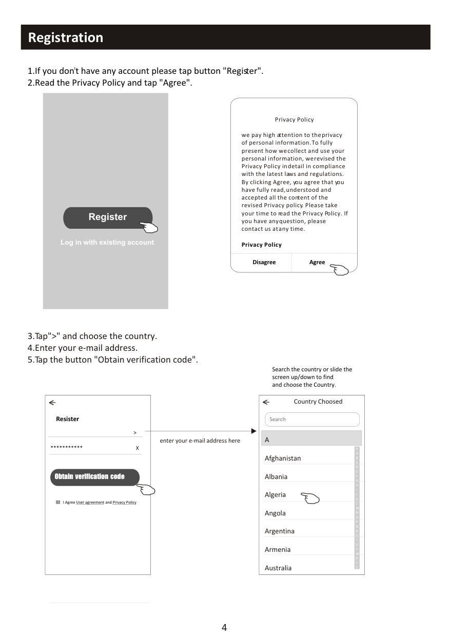
Afghanistan Albania Algeria Angola Argentina Armenia Australia
########################################## Obtain verification code
I Agree User agreement and Privacy Policy
|Set Password
6-20 characters for password, including character, numbers
**
<
Done| |---|
|Enter verification code
* * * * * *
<
Verification code is sent to your email:
*@****,Resend(55s)|
|---|
########## Login Login
Register
Log in with existing account
|Login
* >
***
<
Login means that you agree with User Agreement and Privacy Policy
Log in
****
Forgot password
| |---|
enter your account(e-mail) here
enter the password
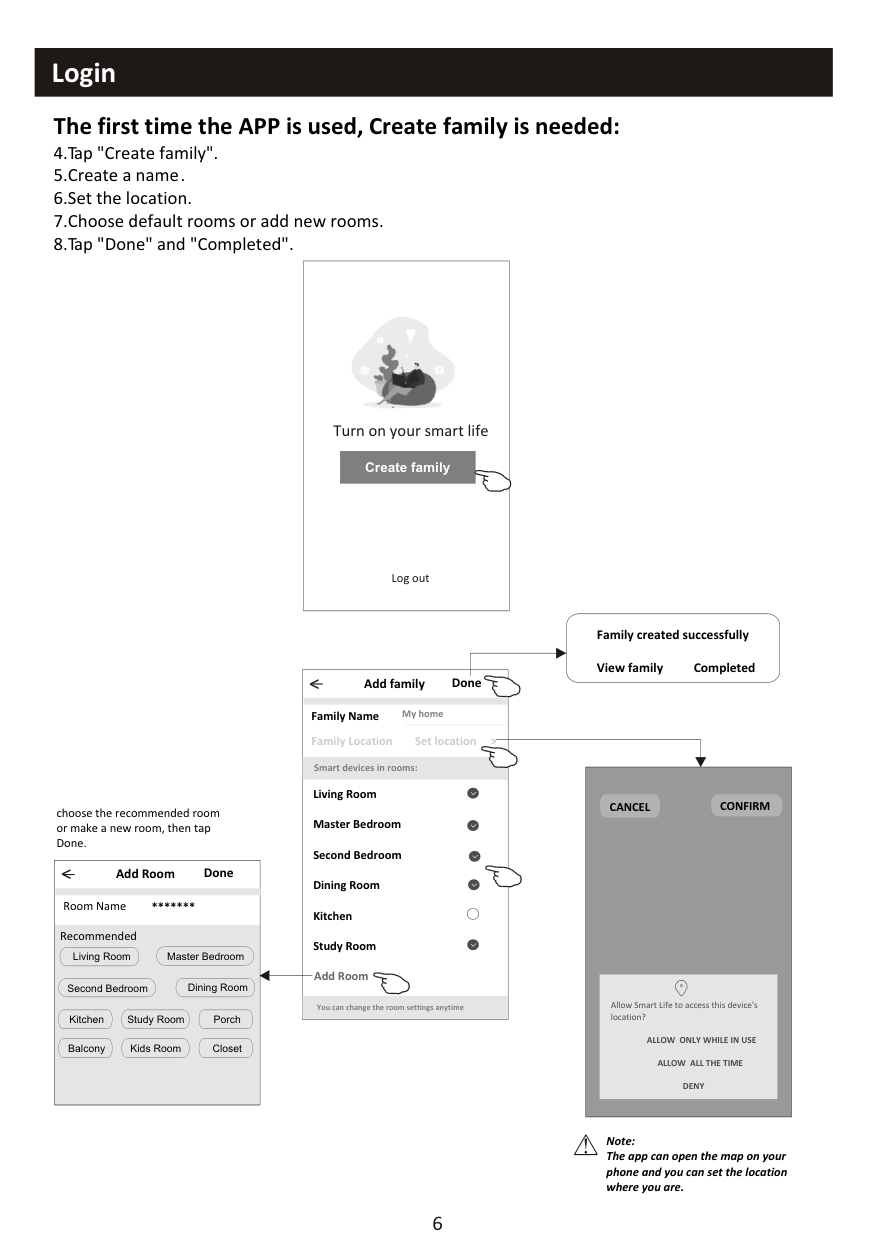
################ The first time the APP is used, Create family is needed:
|Turn on your smart life
Create family
Log out
| |---|
########################################## Family created successfully View family Completed
##################### < Add family Done
##################################################### My home
Family Name
Family Location Set location > Smart devices in rooms: Living Room Master Bedroom Second Bedroom Dining Room Kitchen Study Room Add Room
A
CANCEL CONFIRM
choose the recommended room or make a new room, then tap Done.
|< Add Room Done
| |---| |Living Room Master Bedroom
Second Bedroom Dining Room
Kitchen Study Room Porch
Balcony Kids Room Closet
Room Name Recommended
***|
L
Y
Allow Smart Life to access this device's location?
You can change the room settings anytime
ALLOW ONLY WHILE IN USE ALLOW ALL THE TIME
W
DENY
Z
Note: The app can open the map on your phone and you can set the location where you are.
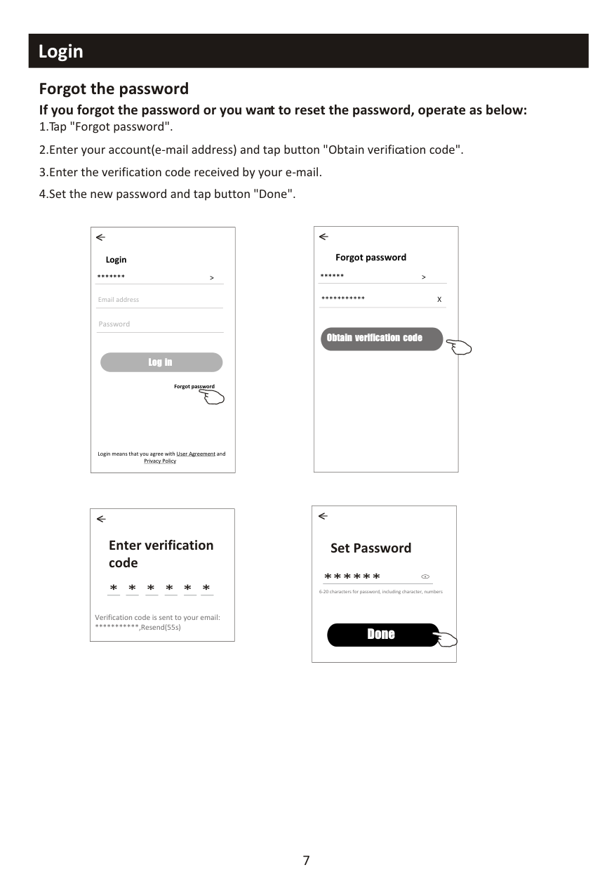
################ Forgot the password If you forgot the password or you want to reset the password, operate as below:
|Forgot password ** >
*** X
<
Obtain verification code|
|---|
|Login
*** >
Email address
<
Log in
Password
Forgot password
Login means that you agree with User Agreement and Privacy Policy
| |---|
|Set Password
6-20 characters for password, including character, numbers
**
<
Done| |---|
|Enter verification code
Verification code is sent to your email:
***,Resend(55s)
* * * * * *
<| |---|
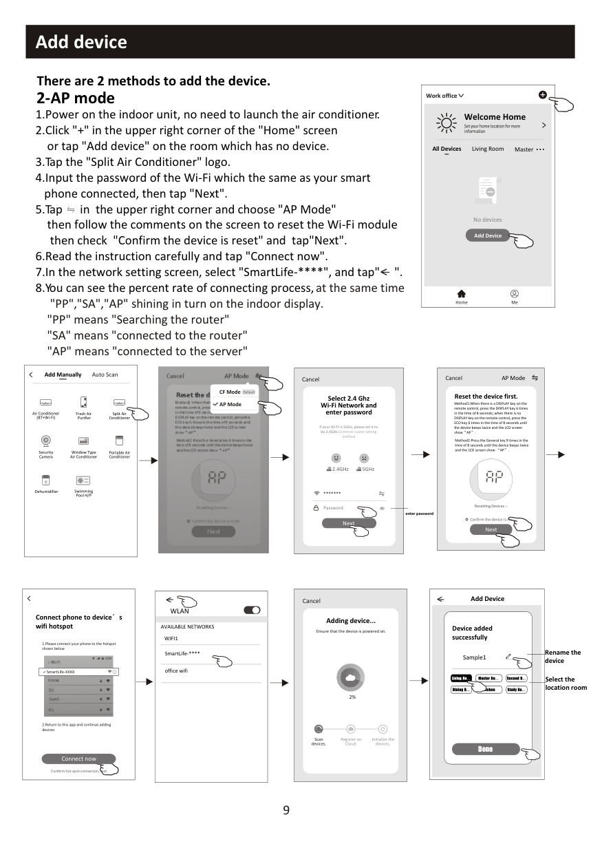
################ There are 2 modes CF(Quick connection) and AP(Access Point) for adding device. CF mode
|<
Welcome Home
Set your home location for more information
All Devices Living Room Master ...
Add Device
Home Me
Work office
<
No devices| |---|
"PP" means "Searching the router" "SA" means "connected to the router" "AP" means "connected to the server"
|< Add Manually Auto Scan
Dehumidifier
Air Conditioner (BT+Wi-Fi)
Fresh Air Purifier
Split Air Conditioner
Window Type Air Conditioner
Portable Air Conditioner
Security Camera
Swimming Pool H/P| |---|
|CF Mode
Reset the device first.
Method1:When there is a DISPLAY key on the remote control, press the DISPLAY key 6 times in the time of 8 seconds; when there is no DISPLAY key on the remote control, press the ECO key 6 times in the time of 8 seconds until the device beeps twice and the LCD screen show CF .
Next
Cancel
Confirm the device is reset.
Resetting Devices
<
Method2:Press the General key 9 times in the time of 8 seconds until the device beeps twice and the LCD screen show CF .| |---|
|Select 2.4 Ghz Wi-Fi Network and enter password
Next
Cancel
If your Wi-Fi is 5GHz, please set it to bo 2.4GHz.Common router setting method
2.4GHz 5GHz
***
Password
| |---|
enter password
|Adding device...
Cancel
Ensure that the device is powered on.

2%


Scan devices.
Register on Cloud.
Initialize the devices.|

|---|
Add Device<
Device added successfully
Rename the device
Sample1
Select the location room
Living Ro... Master Be... Second B...
Dining R... Kitchen Study Ro...
Done
################ There are 2 methods to add the device. 2-AP mode
|<
Welcome Home
Set your home location for more information
All Devices Living Room Master ...
Add Device
Home Me
Work office
<
No devices| |---|
then check "Confirm the device is reset" and tap"Next".
<
"PP" means "Searching the router" "SA" means "connected to the router" "AP" means "connected to the server"
|< Add Manually Auto Scan
Dehumidifier
Air Conditioner (BT+Wi-Fi)
Fresh Air Purifier
Split Air Conditioner
Window Type Air Conditioner
Portable Air Conditioner
Security Camera
Swimming Pool H/P| |---|
|AP Mode
Reset the device first.
Method1:When there is a DISPLAY key on the remote control, press the DISPLAY key 6 times in the time of 8 seconds; when there is no DISPLAY key on the remote control, press the ECO key 6 times in the time of 8 seconds until the device beeps twice and the LCD screen show AP .
Next
Cancel
Confirm the device is reset.
Resetting Devices
<
Method2:Press the General key 9 times in the time of 8 seconds until the device beeps twice and the LCD screen show AP .

CF Mode AP Mode
Default
| |---|
|AP Mode
Reset the device first.
Method1:When there is a DISPLAY key on the remote control, press the DISPLAY key 6 times in the time of 8 seconds; when there is no DISPLAY key on the remote control, press the ECO key 6 times in the time of 8 seconds until the device beeps twice and the LCD screen show AP .
Next
Cancel
Confirm the device is reset.
Resetting Devices
Method2:Press the General key 9 times in the time of 8 seconds until the device beeps twice and the LCD screen show AP .| |---|
########################################################## Cancel
#################################################### Select 2.4 Ghz Wi-Fi Network and enter password
If your Wi-Fi is 5GHz, please set it to bo 2.4GHz.Common router setting method
############################################################### 2.4GHz 5GHz
***
Password
enter password
Next
|<
Connect phone to device s wifi hotspot
Connect now
1.Please connect your phone to the hotspot shown below
Wi-Fi
Home 5G Guest 4G
12:30 <

|SmartLife-XXXX
| |---|
2.Return to this app and continue adding devices
Confirm hot spot connecton,next| |---|
|<
WLAN
AVAILABLE NETWORKS
SmartLife-****
office wifi
WIFI1| |---|
|Adding device...
Cancel
Ensure that the device is powered on.

2%


Scan devices.
Register on Cloud.
Initialize the devices.| |---|
9
Add Device<
Device added successfully
Rename the device
Sample1
Select the location room
Living Ro... Master Be... Second B...
Dining R Kitchen Study Ro...
Done
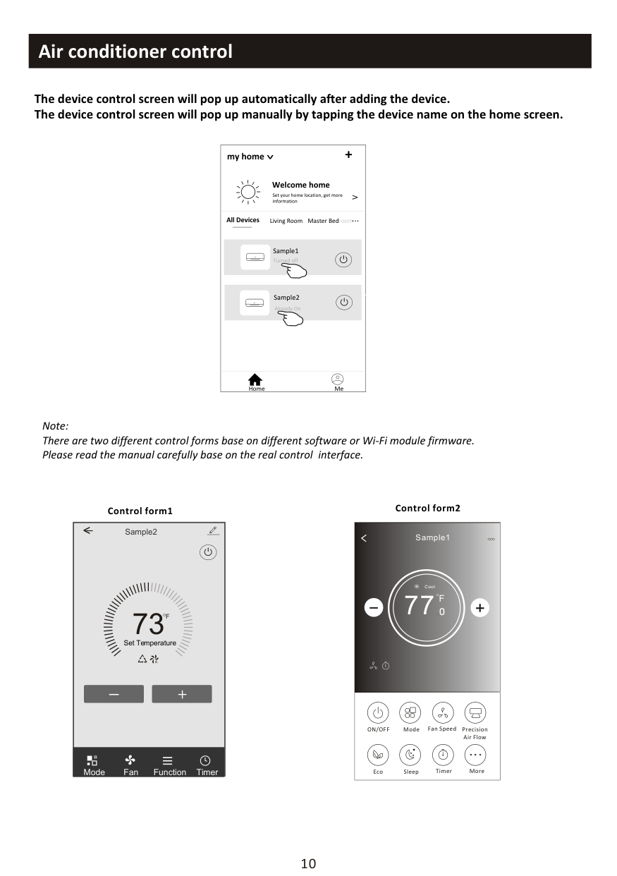
############################# The device control screen will pop up automatically after adding the device. The device control screen will pop up manually by tapping the device name on the home screen.
my home +
################################# >
############################################## Welcome home
Set your home location, get more information
V
Living Room roomMaster Bed...
All Devices
Turned off
<
Already On
Home Me
Note: There are two different control forms base on different software or Wi-Fi module firmware. Please read the manual carefully base on the real control interface.
Control form1 Control form2
|
Sample1
77
Cool
0
F| |---| |ON/OFF Fan Speed Precision Air Flow
MoreEcoSleep
Mode
Timer
|
Sample2<
##### 73
F
Set Temperature
TimerFunctionFanMode
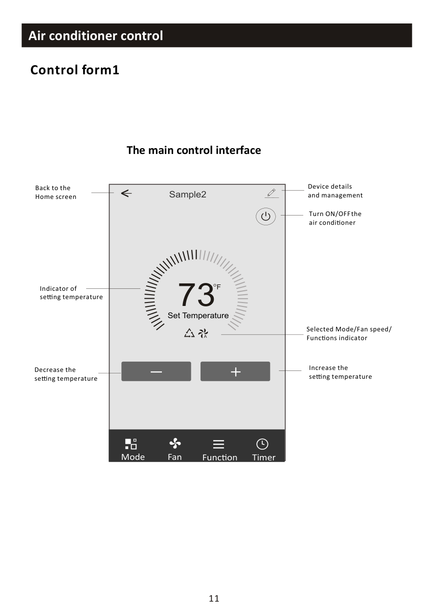
########## Control form1
################ The main control interface
Device details and management
Back to the Home screen
Sample2<
Turn ON/OFF the air condi oner
73
F
Indicator of se ng temperature
Set Temperature
Selected Mode/Fan speed/ Func ons indicator
Increase the se ng temperature
Decrease the se ng temperature
TimerFunc onFanMode
########## Control form1-Mode setting
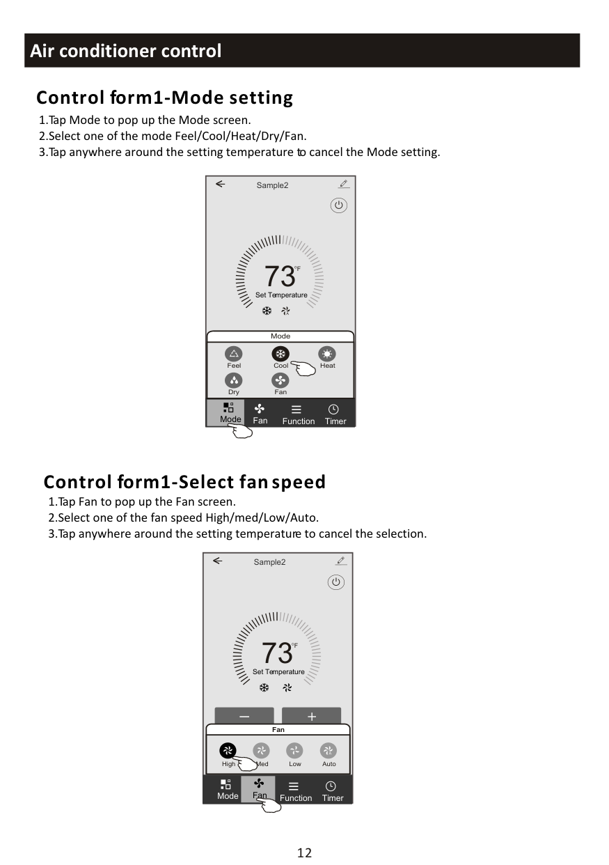
Sample2<
##### 73
F
Set Temperature
Mode
Feel Cool Heat
FanDry
Mode
TimerFunctionFan
########## Control form1-Select fan speed
Sample2<
##### 73
F
Set Temperature
######################################################## Fan
Med Low AutoHigh
Mode Fan
TimerFunction
########## Control form1-Function setting
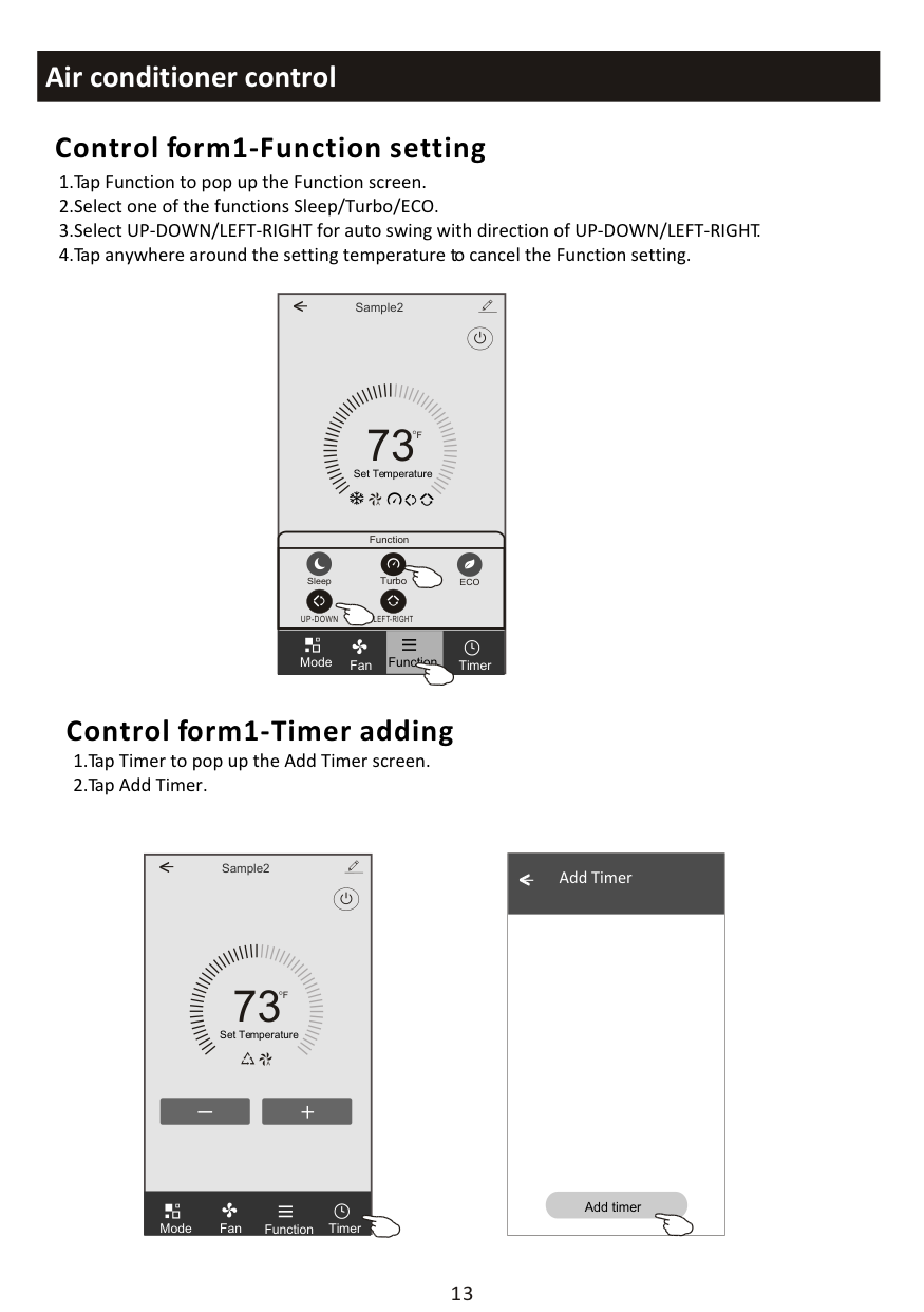
Sample2<
##### 73
F
Set Temperature
Function
TurboSleep ECO
UP-DOWN LEFT-RIGHT
Function
Mode
TimerFan
########## Control form1-Timer adding
Sample2<
##### 73
F
Set Temperature
TimerFunctionFanMode
|< Add Timer
Add timer
| |---|
########## Control form1-Timer adding
3.Select the time, select the repeat days and Timer on/off. 4.Select the Mode/Fan speed/Function and select the setting temperature for Timer on. 5.Tap Save to add the timer.
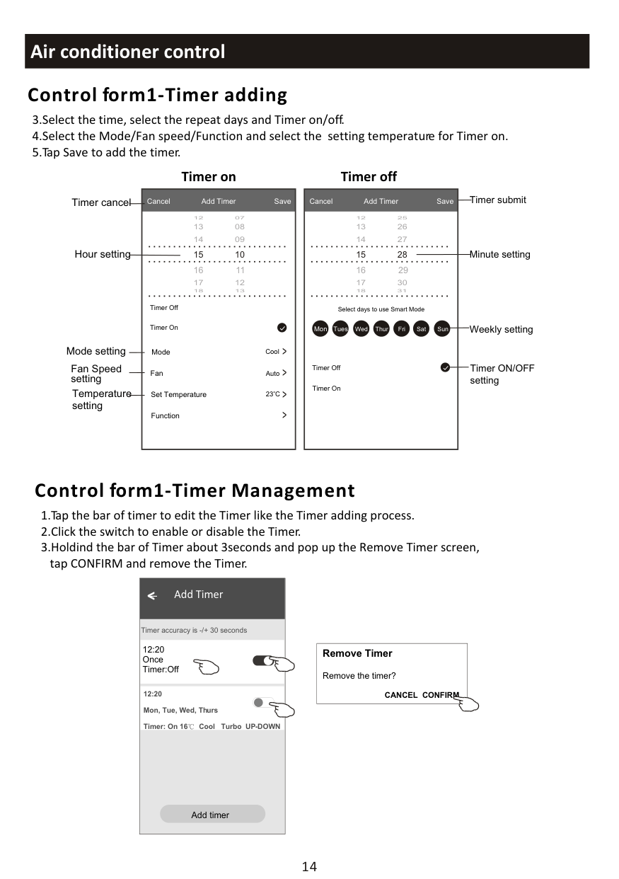
##################### Timer on Timer off
Timer cancel Timer submit
Cancel Add Timer Save
Cancel Add Timer Save
Hour setting Minute setting
14 09
13 08
12 07
14 27
13 26
12 25
Timer Off
Select days to use Smart Mode
Weekly setting
Timer On
Mon Tues Wed Thur Fri Sat Sun
< < < <
Mode setting
Cool
Mode
Fan Speed setting
Timer ON/OFF setting
Timer Off
Fan
Auto
Timer On
Temperature setting
Set Temperature
23 C
Function
########## Control form1-Timer Management
|WLAN
Add timer
Timer accuracy is -/+ 30 seconds
12:20 Once Timer:Off
12:20 Mon, Tue, Wed, Thurs Timer: On 16 Cool Turbo UP-DOWN
| |---|
|Remove Timer
Remove the timer?
CANCEL CONFIRM| |---|
########## Air condi oner control
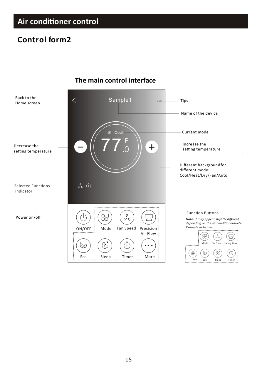
########## Control form2
Back to the Home screen
Decrease the se ng temperature
Selected Func ons indicator
Power on/off
The main control interface

Sample1
Tips
Name of the device
Current mode
Cool
77
F
Increase the se ng temperature
############## 0
Different background for different mode: Cool/Heat/Dry/Fan/Auto
|ON/OFF
|Fan Speed Precision Air Flow
Mode| |---|---| |MoreEcoSleepTimer
|MoreEcoSleepTimer
|
Func on Bu ons
Note: it may appear slightly different , depending on the air conditioner model. Example as below:
| |Fan Speed Swing FlowMode| |---|---| |Eco Sleep TimerTurbo
|Eco Sleep TimerTurbo
|
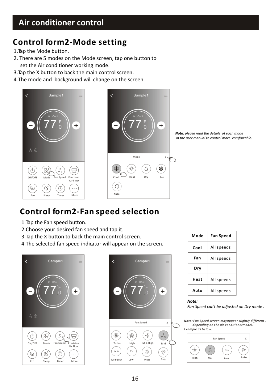
########## Control form2-Mode setting
|
Sample1
77
Cool
0
F| |---| |ON/OFF Fan Speed Precision Air Flow
MoreEcoSleep
Mode
Timer
|
|BackSample1

77
Cool
0
F| |---| |Cool Dry FanHeat
Auto
Mode X|
Note: please read the details of each mode
in the user manual to control more comfortable.
########## Control form2-Fan speed selection
|Mode|Fan Speed| |---|---| |Cool|All speeds| |Fan|All speeds| |Dry| | |Heat|All speeds| |Auto|All speeds|
|BackSample1

77
Cool
0
F| |---| |Turbo Mid-High Midhigh
Fan Speed X
Mid-Low Mute AutoLow|
|
Sample1
77
F
Cool
0
| |---| |ON/OFF Fan Speed Precision Air Flow
MoreEcoSleep
Mode
Timer
|
Note: Fan Speed can't be adjusted on Dry mode .
Note: Fan Speed screen may appear slightly different ,
depending on the air conditioner model. Example as below:
|Midhigh
Fan Speed X
AutoLow| |---|
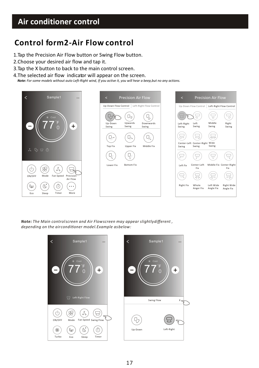
########## Control form2-Air Flow control
Note: For some models without auto Left-Right wind, If you active it, you will hear a beep,but no any actions.
|
Sample1
77
Cool
0
F| |---| |ON/OFF Fan Speed Precision Air Flow
MoreEcoSleep
Mode
Timer
|
|Get verification code

< Precision Air Flow
Up-Down Flow Control Left-Right Flow Control
Downwards Swing
Up-Down Swing
Upwards Swing
Middle FixTop FixUpper Fix
Lower Fix Bottom Fix| |---|
|
< Precision Air Flow
Up-Down Flow Control Left-Right Flow Control
Right Swing
Left-Right Swing
Left Swing
Middle Swing
Center-Left Swing
Center-Right Swing
Wide Swing
Center-Right Fix
Left fix Center-Left Fix
Middle Fix
Right Wide Angle Fix
Right Fix Whole Anger Fix
Left Wide Angle Fix| |---|
Note: The Main control screen and Air Flow screen may appear slightly different , depending on the air conditioner model.Example as below:
|
Sample1
77
Cool
0
Le -Right Flow
F| |---| |ON/OFF Fan Speed Swing Flow
Eco Sleep
Mode
TimerTurbo
|
|BackSample1

77
Cool
0
F|
|---| |Swing Flow X
Up-Down Le -Right|
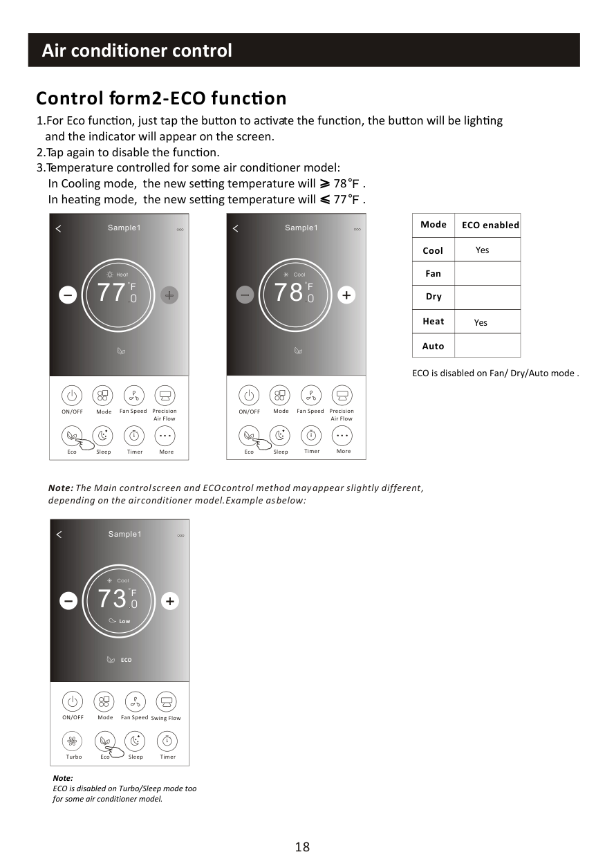
########## Control form2-ECO func on
F F
|
Sample1
78
Cool
0
F| |---| |ON/OFF Fan Speed Precision Air Flow
MoreEcoSleep
Mode
Timer
|
|Mode|ECO enabled| |---|---| |Cool|Yes| |Fan| | |Dry| | |Heat|Yes| |Auto| |
|
Sample1
77
Heat
0
F| |---| |ON/OFF Fan Speed Precision Air Flow
MoreEcoSleep
Mode
Timer
|
ECO is disabled on Fan/ Dry/Auto mode .
Note: The Main control screen and ECO control method may appear slightly different , depending on the air conditioner model.Example as below:
|
Sample1
73
Cool
0
ECO
F
Low| |---| |ON/OFF Fan Speed Swing Flow
Eco Sleep
Mode
TimerTurbo
|
Note: ECO is disabled on Turbo/Sleep mode too for some air conditioner model.
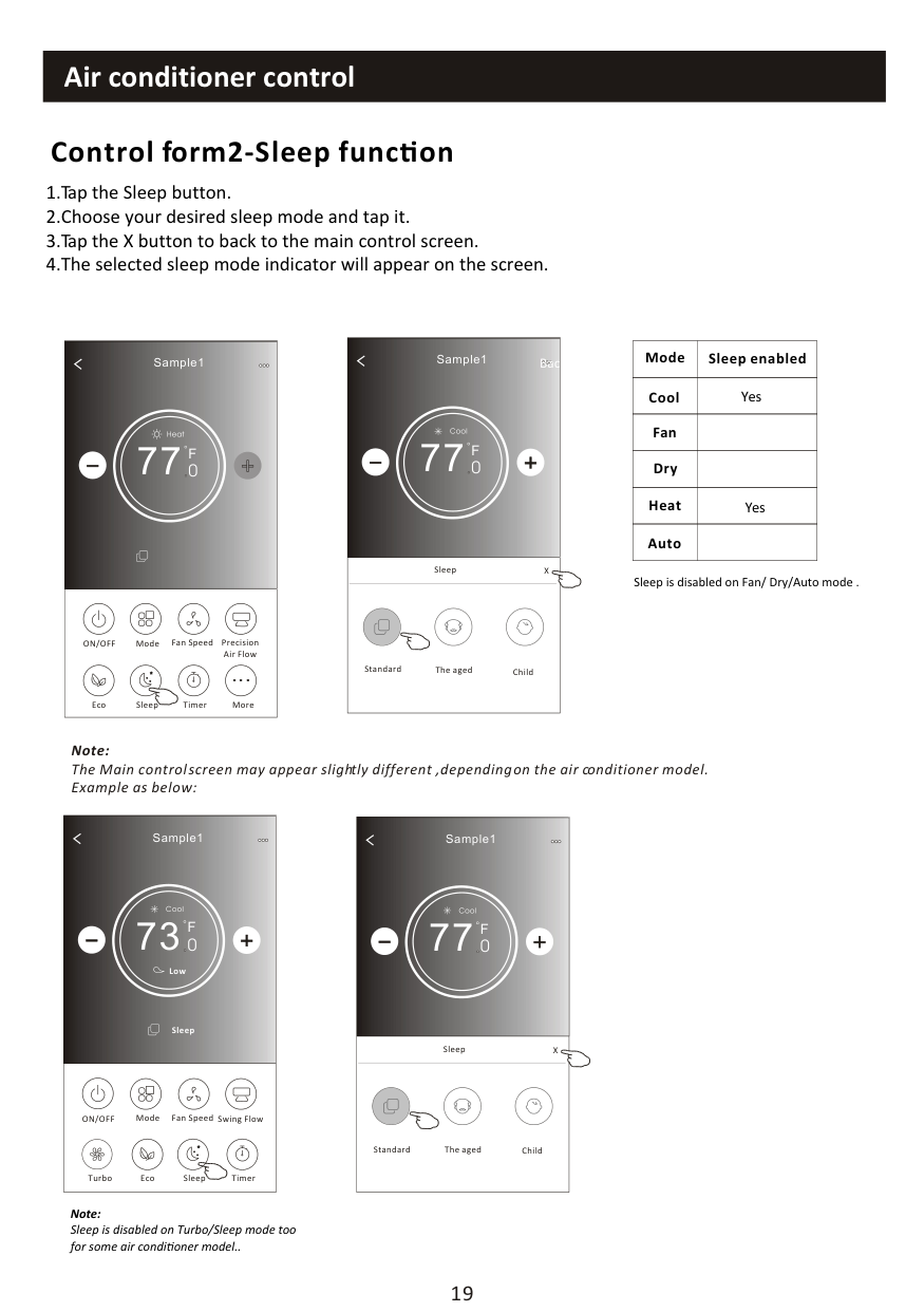
########## Control form2-Sleep func on
|
Sample1
77
Cool
0
F
Back| |---| |Sleep X
Standard ChildThe aged
|
|Mode|Sleep enabled| |---|---| |Cool|Yes| |Fan| | |Dry| | |Heat|Yes| |Auto| |
|
Sample1
77
Heat
0
F| |---| |ON/OFF Fan Speed Precision Air Flow
MoreEcoSleep
Mode
Timer
|
Sleep is disabled on Fan/ Dry/Auto mode .
Note: The Main control screen may appear slightly different ,depending on the air conditioner model. Example as below:
|
Sample1
73
Cool
0
Sleep
F
Low| |---| |ON/OFF Fan Speed Swing Flow
Eco Sleep
Mode
TimerTurbo
|
|BackSample1

77
Cool
0
F| |---| |Sleep X
ChildThe agedStandard
|
Note: Sleep is disabled on Turbo/Sleep mode too for some air conditioner model..
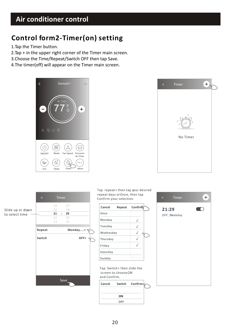
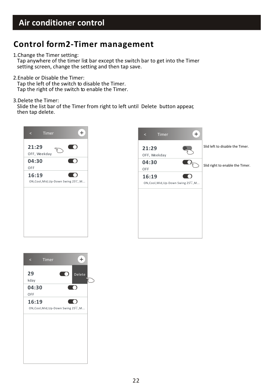
########## Control form2-Timer(on) setting
1.Tap the Timer button. 2.Tap + in the upper right corner of the Timer main screen. 3.Choose the Time/Repeat/Switch OFF then tap Save. 4.The timer(off) will appear on the Timer main screen.
|
Sample1
77
Cool
0
F| |---|
|ON/OFF Fan Speed Precision Air Flow
MoreEcoSleep
Mode
Timer
|
|
< Timer
No Timer| |---|
|
< Timer
19 27
20 28
22 30
23 31
Save

21 : 29
Repeat Monday.... > Switch OFF>| |---|
Slide up or down to select time
Tap repeat > then tap your desired repeat days or Once, then tap Confirm your selection.
|Once Monday Tuesday Wednesday Thursday Friday Saturday Sunday
Cancel Repeat Confirm| |---|
Tap Switch > then slide the
screen to choose ON and Confirm.
|ON
Cancel Switch Confirm
OFF| |---|
|
< Timer 21:29 OFF, Weekday
| |---|
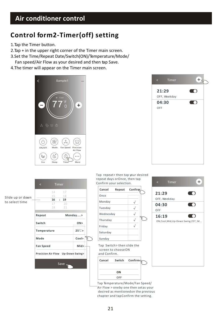
########## Control form2-Timer(off) setting
|
Sample1
77
Cool
0
F| |---| |ON/OFF Fan Speed Precision Air Flow
MoreEcoSleep
Mode
Timer
|
|
< Timer 21:29 OFF, Weekday
| |---|
|04:30 OFF
|
Tap repeat > then tap your desired repeat days or Once, then tap Confirm your selection.
|
< Timer
21:29 OFF, Weekday
| |---| |04:30 OFF| |16:19
ON,Cool,Mid,Up-Down Swing 25 ,M...|

####################################### < Timer
|Once Monday Tuesday Wednesday Thursday Friday Saturday Sunday
Cancel Repeat Confirm| |---|
Save

Slide up or down to select time
Repeat Monday.... > Switch ON> Temperature 25 > Mode Cool> Fan Speed Mid> Precision Air Flow Up-Down Swing>
Tap Switch > then slide the
screen to choose ON and Confirm.
|ON
Cancel Switch Confirm
OFF| |---|
Tap Temperature/Mode/Fan Speed/ Air Flow > one by one then set as your
desired as mentioned on the previous chapter and tap Confirm the setting.
########## Control form2-Timer management
|
< Timer
21:29 OFF, Weekday
| |---| |04:30 OFF| |16:19
ON,Cool,Mid,Up-Down Swing 25 ,M...
| | |
|
< Timer
21:29 OFF, Weekday
| |---| |04:30 OFF| |16:19
ON,Cool,Mid,Up-Down Swing 25 ,M...
| | |
Slid left to disable the Timer.
Slid right to enable the Timer.
|
< Timer
29 kday
Delete| |---| |04:30 OFF| |16:19
ON,Cool,Mid,Up-Down Swing 25 ,M...
| | |
|
Sample1
77
Cool
0
F| |---| |ON/OFF Fan Speed Precision Air Flow
MoreEcoSleep
Mode
Timer
|
Note: The appearance maybe different , some icons
will be hidden if the air conditional do no have this function or do not enable on the current mode.
|
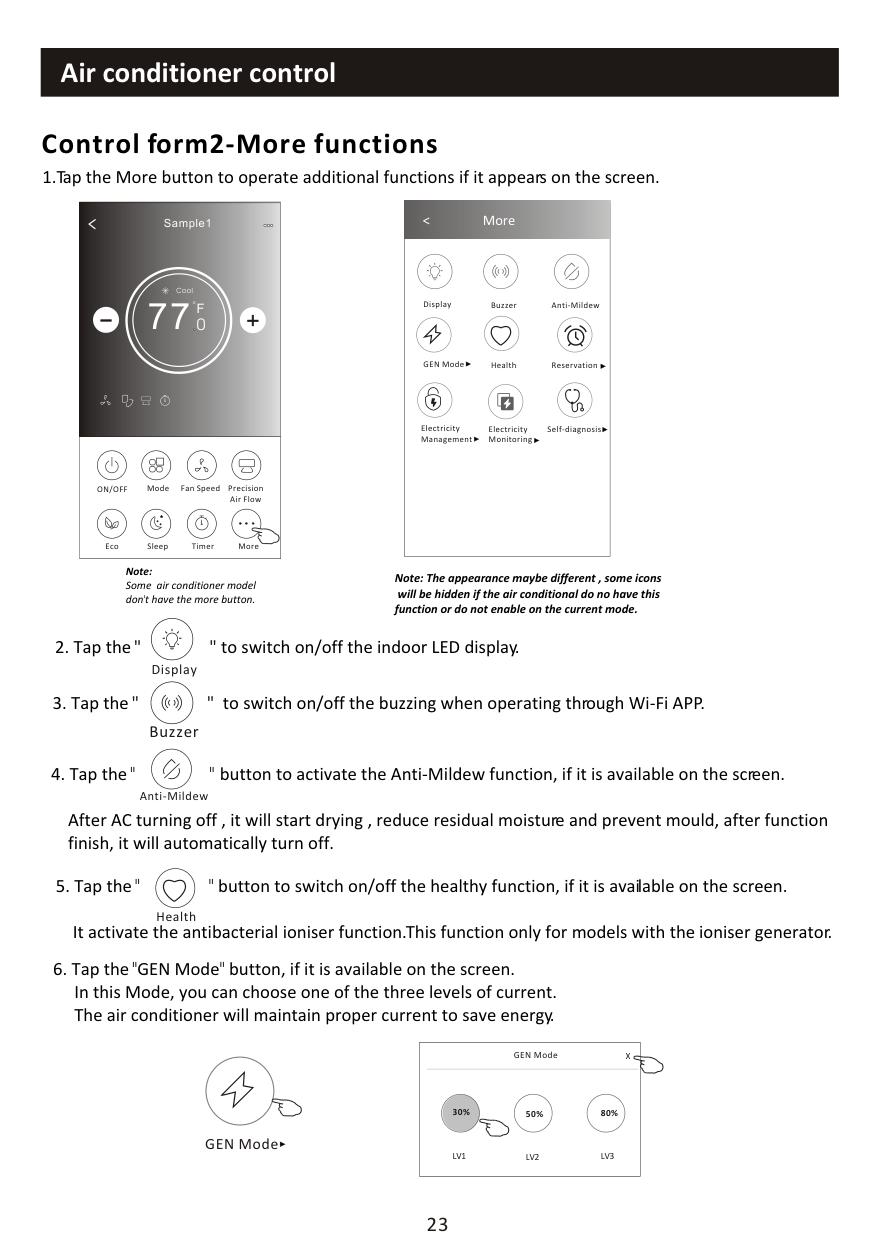
< More
Buzzer Anti-MildewDisplay
Health ReservationGEN Mode
Electricity Monitoring
Self-diagnosisElectricity Management
| |---|
Note:
Some air conditioner model dont have the more button.
After AC turning off , it will start drying , reduce residual moisture and prevent mould, after function finish, it will automatically turn off.
Anti-Mildew
Health
GEN Mode
|GEN Mode X
LV1 LV3LV2
30% 80%50%| |---|


########## Control form2-More functions
############################## 7. Tap the"Electricity Monitoring" button if it is available on the screen.In this function, you can monitor the air conditioner electricity consumption.
|Electricity monitoring
2019-03-11
DAY Month Year
13:00 14:00 15:00 16:00 17:00 18:00 19:00
(Kwh) 0.032
0.024
0.016
0.008
0|Electricity monitoring
2019-03-11
DAY Month Year
13:00 14:00 15:00 16:00 17:00 18:00 19:00
(Kwh) 0.032
0.024
0.016
0.008
0| |---|---| |2019-03-10|2019-03-11| |0kwh Total Electricity Consumption|0.14kwh Total Electricity Consumption| |0hour
Running time statistic|4.6hour
Running time statistics|
You can tap this button to pop up the calender then
|Electricity monitoring
2019-03
DAY Month Year
03-09 03-10 03-11 03-12 03-13 03-14 03-15
(Kwh) 0.16
0.12
0.08
0.04
0|Electricity monitoring
2019-03
DAY Month Year
03-09 03-10 03-11 03-12 03-13 03-14 03-15
(Kwh) 0.16
0.12
0.08
0.04
0| |---|---| |2019-02|2019-03| |0.13kwh Total Electricity Consumption|0.32kwh Total Electricity Consumption| |4.33hour
Running time statistic|10.83hour
Running time statistics|
select the date.
Electricity Monitoring
Self-Cleaning
8 Heat
|
< Reservation 16:19:00 ON,Cool,Mid,Up-Down Swing 25 ,M...
| |---| |After the reservation is set up, the air conditioner will automatically reach your set requirement at your appointment time.|
|
< Reservation
14 17
15 18
17 20
18 21
Save

16 : 19
Repeat setting Monday.... > Temperature 25 > Mode Cool> Fan Speed Mid> Precision Air Flow Up-Down Swing>| |---|
Reservation

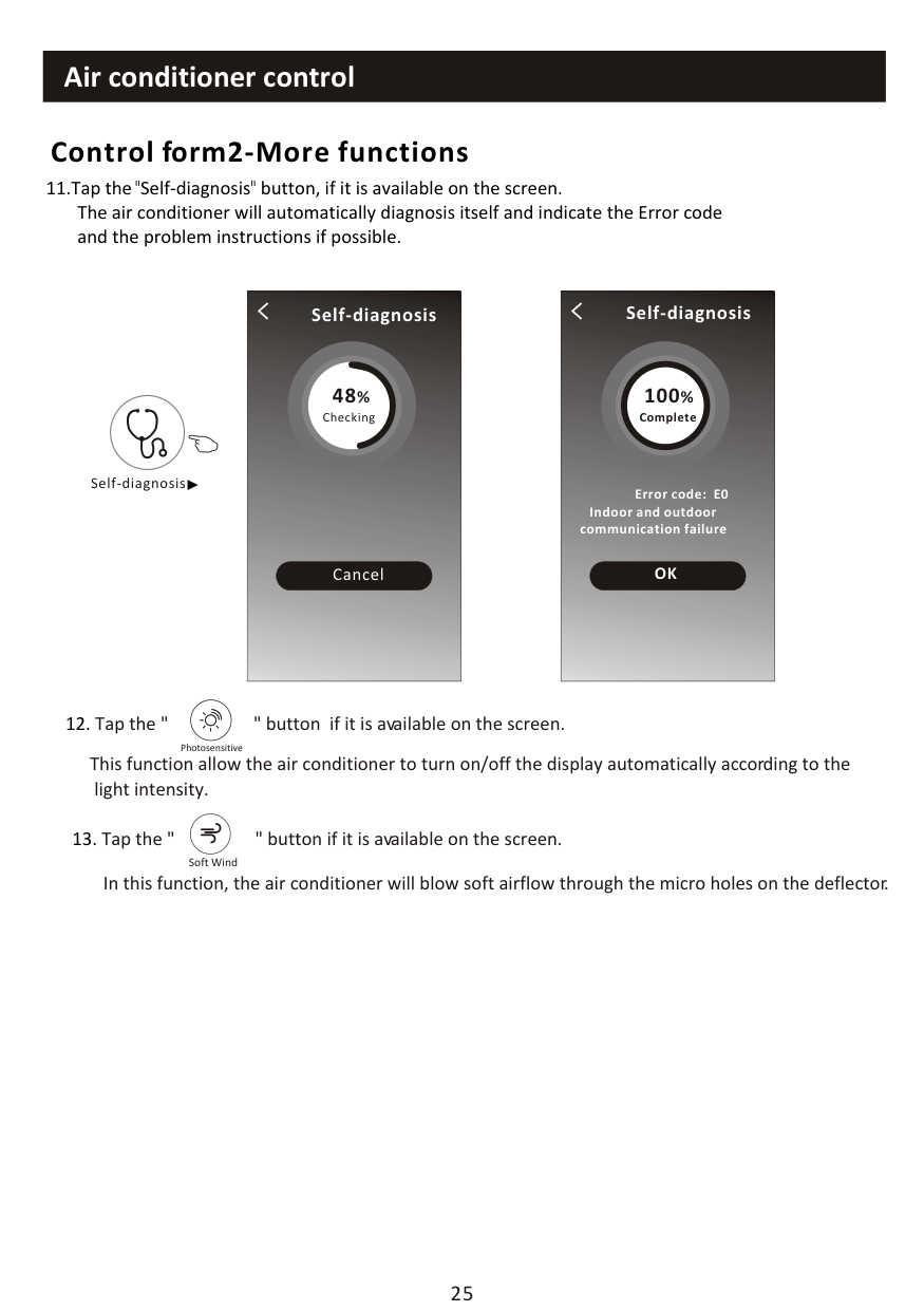
|Self-diagnosis
48%
Checking
Cancel| |---|

|48
OK
Self-diagnosis
100%
Complete
Error code: E0 Indoor and outdoor communication failure|
|---|
Self-diagnosis
Photosensitive
############################## This function allow the air conditioner to turn on/off the display automatically according to the light intensity.
Soft Wind
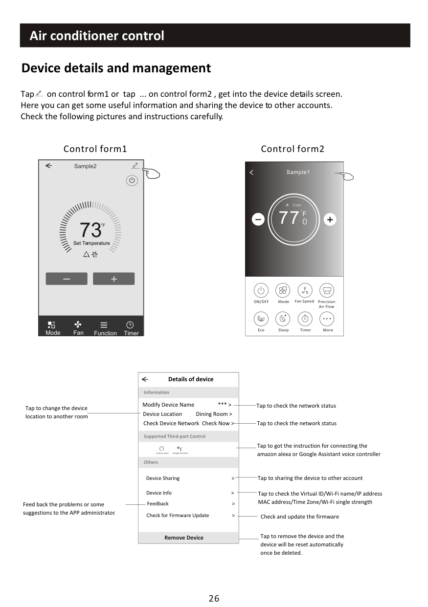
Tap on control form1 or tap ... on control form2 , get into the device details screen. Here you can get some useful information and sharing the device to other accounts. Check the following pictures and instructions carefully.
Control form2Control form1
Sample2<
##### 73
F
Set Temperature
TimerFunctionFanMode
|
Sample1
77
Cool
0
F| |---| |ON/OFF Fan Speed Precision Air Flow
MoreEcoSleep
Mode
Timer
|
|< Details of device
Information
Remove Device
Supported Third-part Control
Others
Modify Device Name *** > Device Location Dining Room > Check Device Network Check Now >
Device Sharing >
Device Info > Feedback > Check for Firmware Update >
| |---|
Tap to check the network status
Tap to change the device location to another room
Tap to check the network status
Tap to got the instruction for connecting the amazon alexa or Google Assistant voice controller
Tap to sharing the device to other account
Tap to check the Virtual ID/Wi-Fi name/IP address
MAC address/Time Zone/Wi-Fi single strengthFeed back the problems or some suggestions to the APP administrator.
Check and update the firmware
Tap to remove the device and the device will be reset automatically once be deleted.
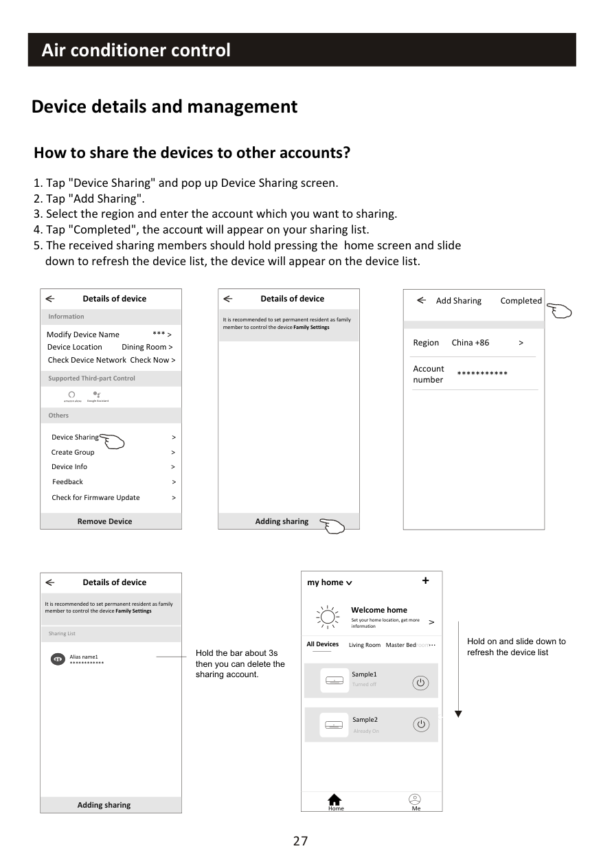
################ How to share the devices to other accounts?
|< Details of device
Information
Remove Device
Supported Third-part Control
Others
Modify Device Name *** > Device Location Dining Room > Check Device Network Check Now >
Device Sharing > Create Group > Device Info > Feedback > Check for Firmware Update >
| |---|
|< Details of device
Adding sharing
It is recommended to set permanent resident as family member to control the device Family Settings| |---|
|< Add Sharing Completed
Region China +86 >
Account number
***| |---|
|< Details of device
Adding sharing
It is recommended to set permanent resident as family member to control the device Family Settings
Sharing List
Alias name1
****
| |---|
Hold the bar about 3s then you can delete the sharing account.
my home +
################################# >
############################################## Welcome home
Set your home location, get more information
V
############################################### Hold on and slide down to refresh the device list
Living Room roomMaster Bed...
All Devices
Turned off
<
Already On
Home Me
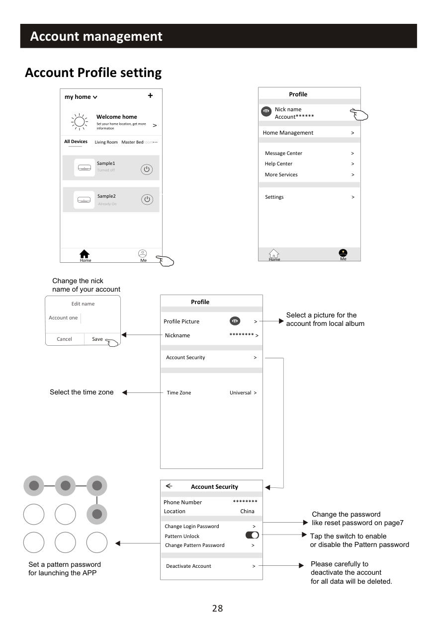
########## Account Profile setting
my home +
################################# >
############################################## Welcome home
Set your home location, get more information
V
Living Room roomMaster Bed...
All Devices
Turned off
<
Already On
Home Me
|Profile
Nick name > Account**
Message Center > Help Center > More Services >
Settings >
Home Management >
Home Me
| |---|
Change the nick name of your account
|Profile
Profile Picture >
Account Security >
Time Zone Universal >
Nickname **** >
| |---|
Edit name
Select a picture for the account from local album
Account one
Cancel Save
Select the time zone
|Account Security
Phone Number ****
Change Login Password >
Deactivate Account >
Location China
<
Pattern Unlock Change Pattern Password >| |---|
Change the password like reset password on page7
Tap the switch to enable or disable the Pattern password
Please carefully to deactivate the account for all data will be deleted.
Set a pattern password for launching the APP
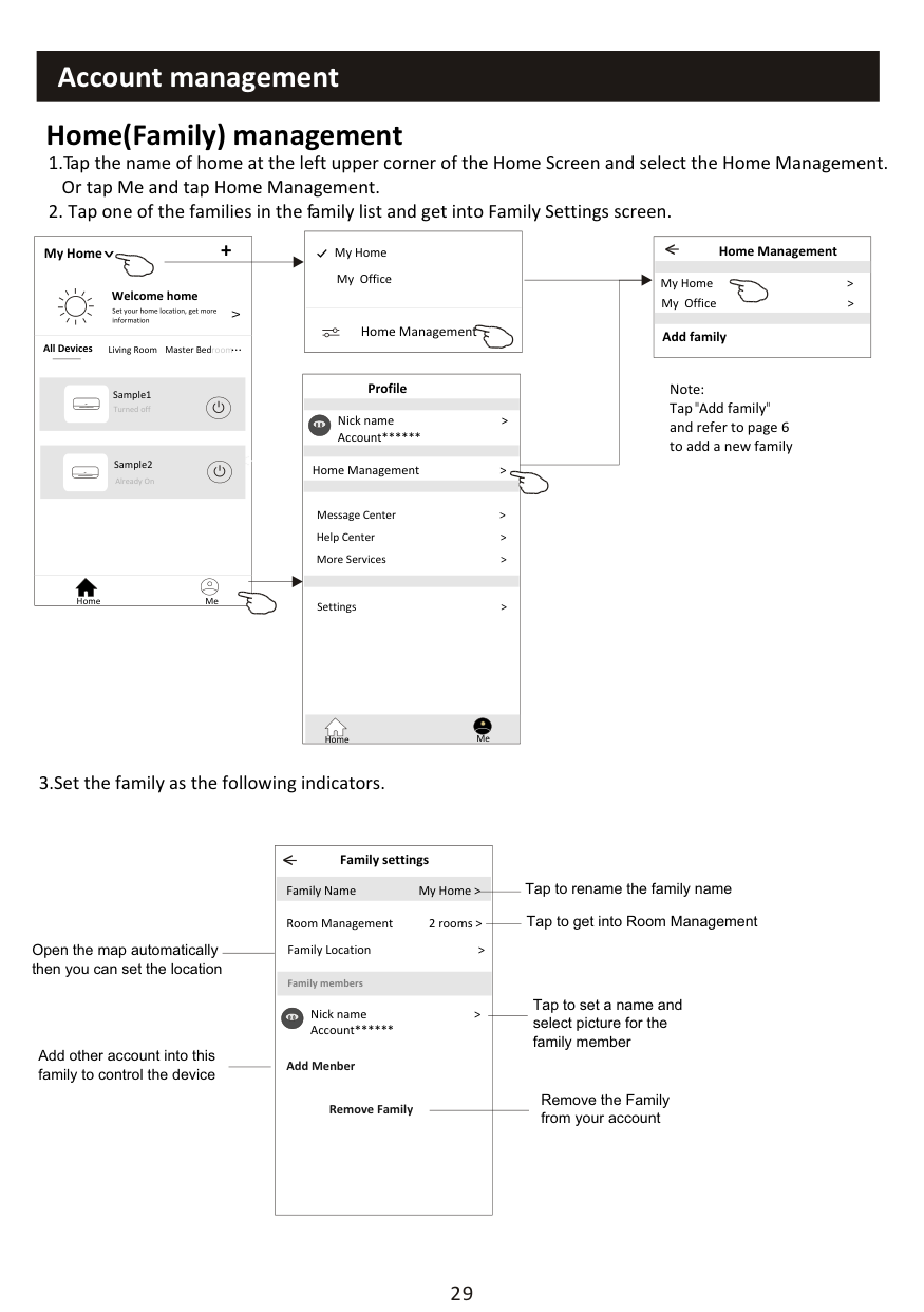
########## Home(Family) management
|Home Management >
My Home My Office| |---|
My Home +
|Home Management
My Home > My Office >
<
Add family|
|---|
################################# >
############################################## Welcome home
Set your home location, get more information
V
Living Room roomMaster Bed...
All Devices
########################################## Profile
Note: Tap"Add family" and refer to page 6 to add a new family
Turned off
Nick name > Account**
<
Home Management >
Already On
Message Center > Help Center > More Services >
Home Me
Settings >
Home Me
3.Set the family as the following indicators.
|< Family settings
Family members
Room Management 2 rooms > Family Location >
Family Name My Home >
Remove Family
Add Menber
Nick name > Account**
| |---|
Tap to rename the family name
Tap to get into Room Management
Open the map automatically then you can set the location
Tap to set a name and select picture for the family member
Add other account into this family to control the device
Remove the Family from your account
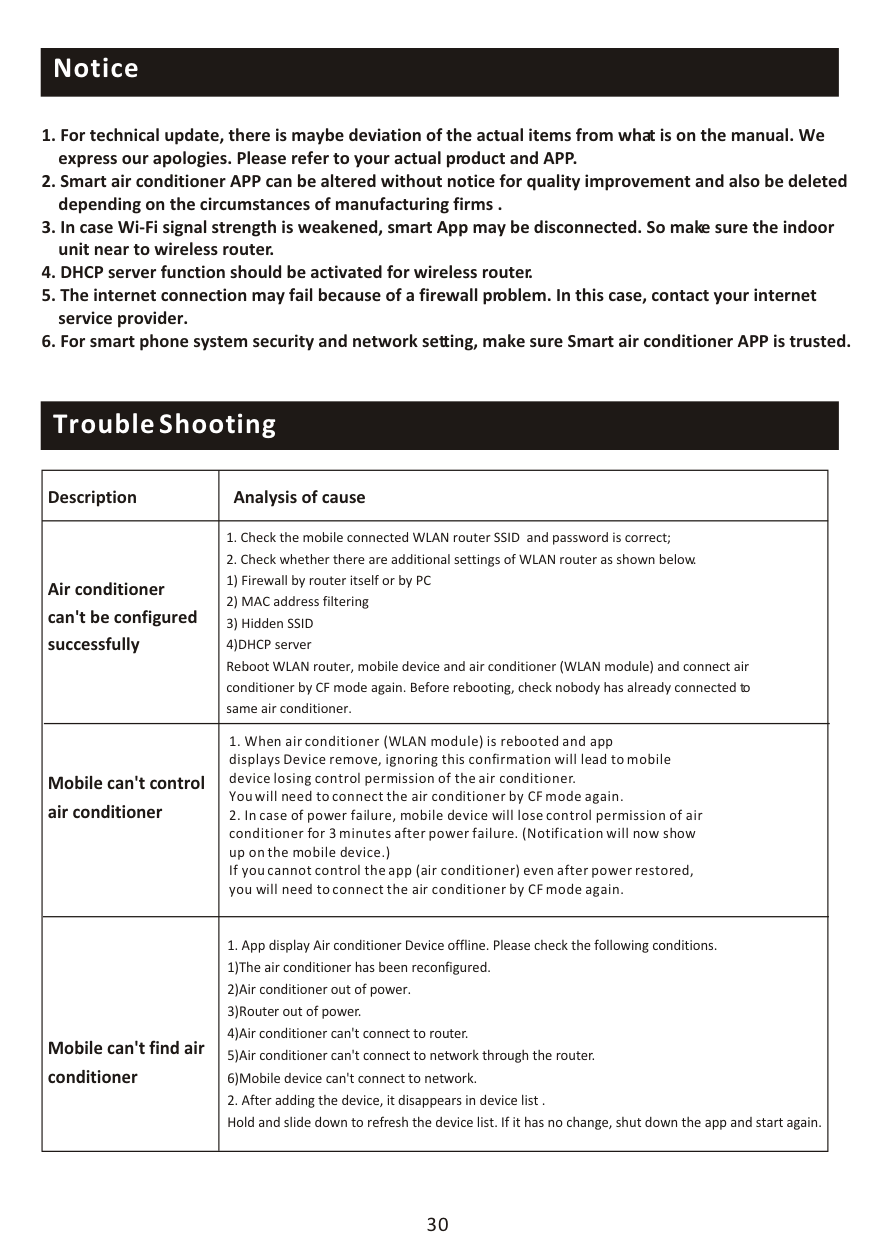
########## Notice
########## Trouble Shooting
|Description|Analysis of cause| |---|---| |Air conditioner can't be configured successfully|1. Check the mobile connected WLAN router SSID and password is correct;
2. Check whether there are additional settings of WLAN router as shown below.
1) Firewall by router itself or by PC
2) MAC address filtering
3) Hidden SSID
4)DHCP server Reboot WLAN router, mobile device and air conditioner (WLAN module) and connect air conditioner by CF mode again. Before rebooting, check nobody has already connected to same air conditioner.
| |Mobile can't control air conditioner|1. When air conditioner (WLAN module) is rebooted and app displays Device remove, ignoring this confirmation will lead to mobile device losing control permission of the air conditioner. You will need to connect the air conditioner by CF mode again.
2. In case of power failure, mobile device will lose control permission of air conditioner for 3 minutes after power failure. (Notification will now show up on the mobile device.) If you cannot control the app (air conditioner) even after power restored, you will need to connect the air conditioner by CF mode again.
| |Mobile can't find air conditioner|1. App display Air conditioner Device offline. Please check the following conditions.
1)The air conditioner has been reconfigured.
2)Air conditioner out of power.
3)Router out of power.
4)Air conditioner can't connect to router.
5)Air conditioner can't connect to network through the router.
6)Mobile device can't connect to network.
2. After adding the device, it disappears in device list . Hold and slide down to refresh the device list. If it has no change, shut down the app and start again.
|
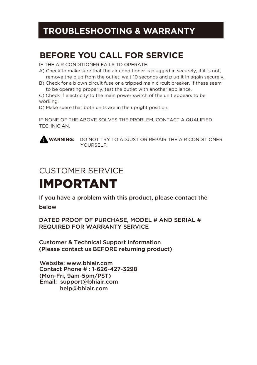
############ TROUBLESHOOTING & WARRANTY
############# BEFORE YOU CALL FOR SERVICE
IF THE AIR CONDITIONER FAILS TO OPERATE:
IF NONE OF THE ABOVE SOLVES THE PROBLEM, CONTACT A QUALIFIED TECHNICIAN.
WARNING: DO NOT TRY TO ADJUST OR REPAIR THE AIR CONDITIONER
YOURSELF.
CUSTOMER SERVICE
#### IMPORTANT
If you have a problem with this product, please contact the below
DATED PROOF OF PURCHASE, MODEL # AND SERIAL # REQUIRED FOR WARRANTY SERVICE
Customer & Technical Support Information (Please contact us BEFORE returning product)
Website: www.bhiair.com
Contact Phone # : 1-626-427-3298
(Mon-Fri, 9am-5pm/PST)