
Della Mini Split Air Conditioner
Ask AI
— answers from the official manualAnswers from the official manual.
Common questions
Common Questions
29 totalWhat is the recommended minimum floor area required for installing the Della Mini Split?
The room for installation, use, repair, and storage of the air conditioner should be greater than 54 sq ft / 5m². This minimum space requirement ensures safe operation and proper refrigerant handling. Failure to maintain this space may result in safety hazards related to refrigerant exposure.
How do I clean the air filter on my indoor unit?
Open the front panel, pull down the air filter, and clean it with soapy water. Air dry the filter completely (below 113°F / 45°C), then put it back in its original position. Check and clean the air filter regularly to prevent dust accumulation, especially if your environment is dusty or has poor air quality.
What does error code E5 mean?
Error code E5 indicates a communication error between the outdoor unit and the indoor unit. This is a communication problem between parts that requires professional diagnosis. For detailed troubleshooting, visit dellahome.com/pages/serena-troubleshooting for model-specific diagnostic information.
How often should I run the self-cleaning function?
It is recommended to operate the self-cleaning function once every 3 months. The function runs for 30-50 minutes and helps carry away accumulated dirt and bacteria from the indoor evaporator. It is best to run this when the indoor ambient temperature is under 86°F / 30°C and outdoor temperature is between 41°F - 86°F / 5°C - 30°C.
What is the maximum distance allowed between indoor and outdoor units?
The maximum distance between the indoor and outdoor units is 82 ft / 25 m. The standard pipe length is 16.4 ft / 5 m, and the maximum elevation difference is 49 ft / 15 m. If you exceed these distances, additional refrigerant charge may be required.
What should I do if the remote control stops working?
First, check if the remote control is too far from the indoor unit or if there is an obstruction between them. Replace the batteries if they have run out. Check if the child lock function is activated and deactivate it if necessary. If the display on the indoor unit is not lit, check the power supply or circuit breaker.
Show 23 more questions
What is the warranty coverage for a new Della Mini Split system?
How do I set up the Wi-Fi connection for the Della+ app?
What temperature range can I set on the air conditioner?
What should I do if water is dripping from the outdoor unit?
Can I install this air conditioner myself, or do I need a professional?
What should I do if I suspect a refrigerant leak?
How much space do I need to safely install and operate this air conditioner?
How should I bundle the line set for my installation?
What is the minimum room size required for installing this air conditioner?
Why is vacuum pumping important for my AC installation?
What are the 5 most important things I need to know before installing my Della Mini Split AC?
What is R32 refrigerant and why should I be careful with it?
What should I do if the air outlet of my indoor or outdoor unit is obstructed?
Do I need to hire a professional to install my mini split AC?
What electrical safety precautions should I take during installation?
How can I contact Della support if I have installation questions?
What refrigerant does this unit use and what safety concerns should I know?
What are the most important things I need to know before installing my Della Mini Split AC?
What is vacuum pumping and why is it important?
What should I do after completing the installation?
What safety precautions should I take with the power cord?
How should I bundle the refrigerant line set during installation?
How can I get help with installation or if I have questions?
Full Manual
68 pages

Multi-Zone Inverter Instruction Manual Installation and Operation Guide Watch video before Installation
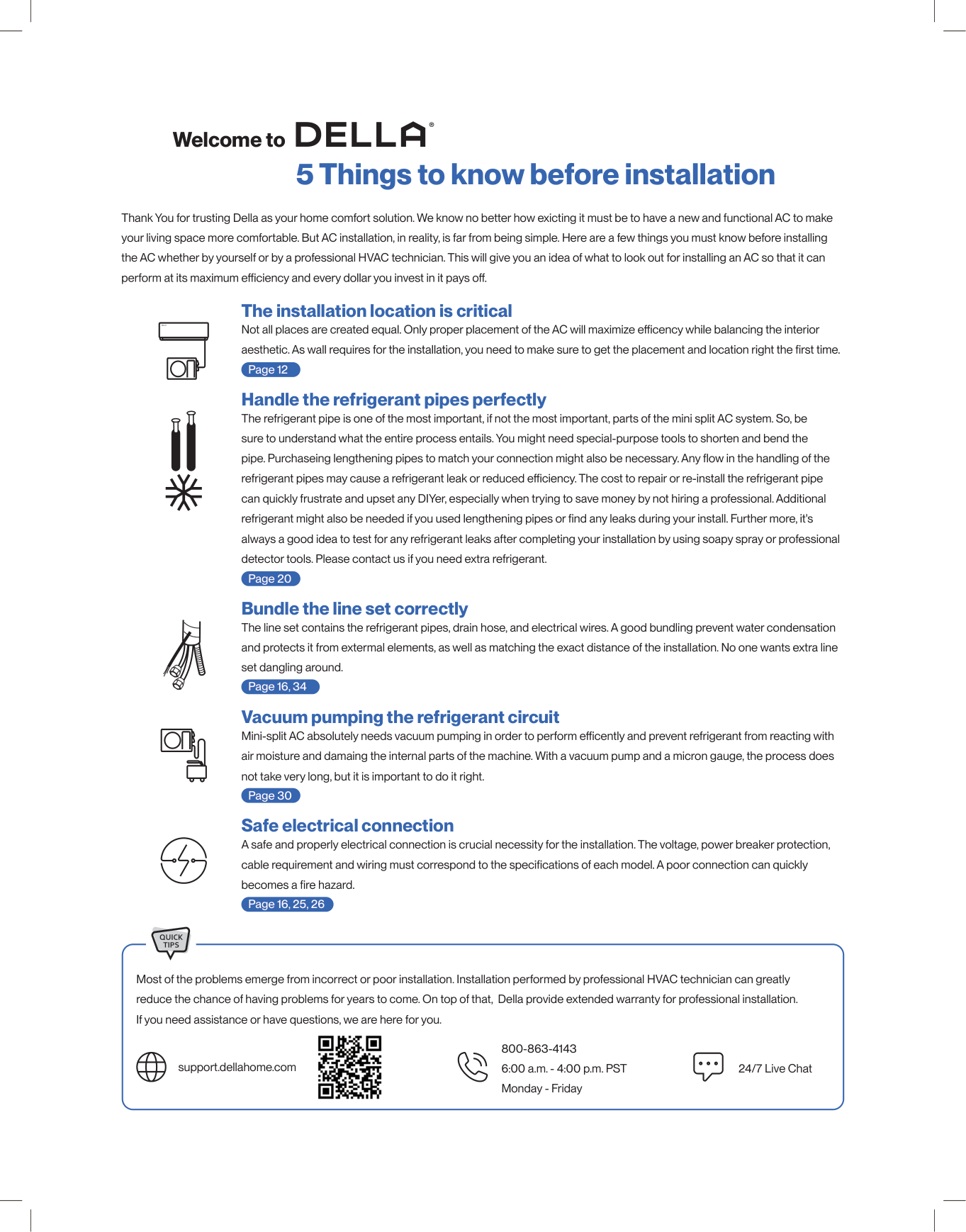
Welcome to 5 Things to know before installation The installation location is critical Handle the refrigerant pipes perfectly Bundle the line set correctly Vacuum pumping the refrigerant circuit Safe electrical connection -14- Thank You for trusting Della as your home comfort solution. We know no better how exicting it must be to have a new and functional AC to make your living space more comfortable. But AC installation, in reality, is far from being simple. Here are a few things you must know before installing the AC whether by yourself or by a professional HVAC technician. This will give you an idea of what to look out for installing an AC so that it can The refrigerant pipe is one of the most important, if not the most important, parts of the mini split AC system. So, be sure to understand what the entire process entails. You might need special-purpose tools to shorten and bend the can quickly frustrate and upset any DIYer, especially when trying to save money by not hiring a professional. Additional always a good idea to test for any refrigerant leaks after completing your installation by using soapy spray or professional detector tools. Please contact us if you need extra refrigerant. -22- The line set contains the refrigerant pipes, drain hose, and electrical wires. A good bundling prevent water condensation and protects it from extermal elements, as well as matching the exact distance of the installation. No one wants extra line set dangling around. -18, 30- air moisture and damaing the internal parts of the machine. With a vacuum pump and a micron gauge, the process does not take very long, but it is important to do it right. -26- A safe and properly electrical connection is crucial necessity for the installation. The voltage, power breaker protection, -12, 25- Page 12 Page 20 Page 30 Page 16, 34 Page 16, 25, 26 Most of the problems emerge from incorrect or poor installation. Installation performed by professional HVAC technician can greatly reduce the chance of having problems for years to come. On top of that, Della provide extended warranty for professional installation. If you need assistance or have questions, we are here for you. support.dellahome.com 24/7 Live Chat 800-863-4143 6:00 a.m. - 4:00 p.m. PST Monday - Friday
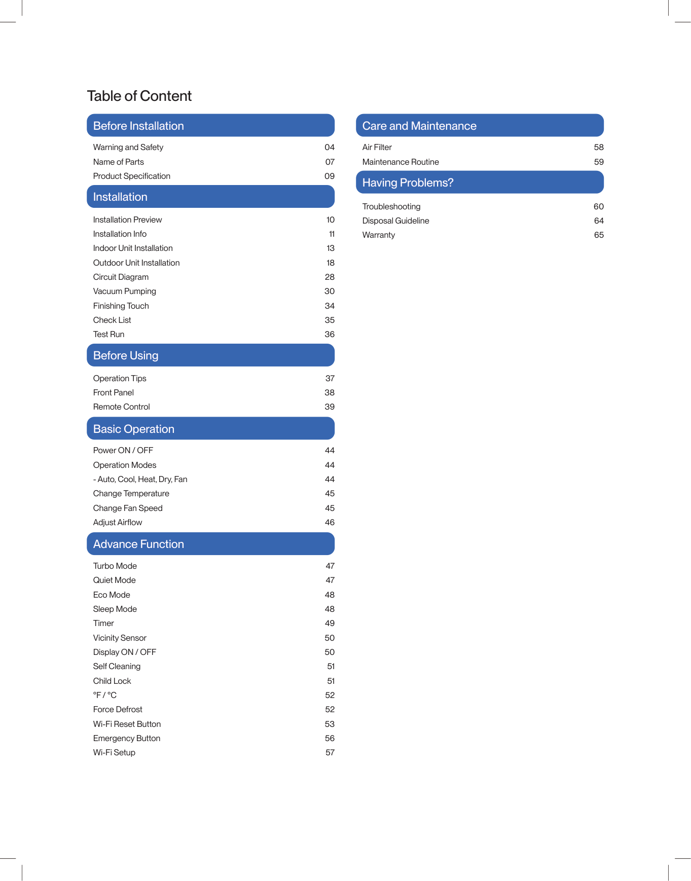
Table of Content Warning and Safety Name of Parts 04 07 09 58 59 60 64 65 Air Filter Maintenance Routine Installation Preview Installation Info Indoor Unit Installation Outdoor Unit Installation Circuit Diagram Vacuum Pumping Finishing Touch Check List Test Run 10 11 13 18 28 30 34 35 36 Troubleshooting Disposal Guideline Warranty Power ON / OFF Operation Modes
°F / °C
Force Defrost Wi-Fi Reset Button Emergency Button Wi-Fi Setup Operation Tips Front Panel Remote Control 37 38 39 Before Installation Care and Maintenance Having Problems? Installation Before Using Basic Operation Advance Function 47 47 48 48 49 50 50 51 51 52 52 53 56 57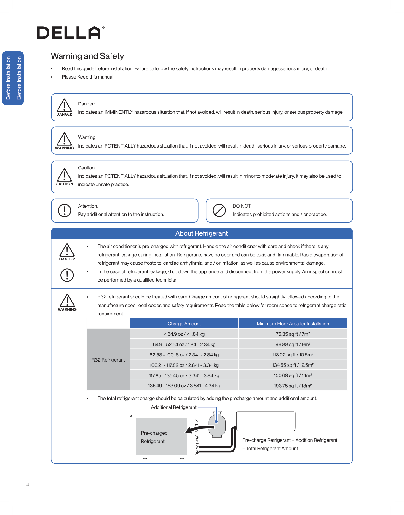
4 Before Installation Before Installation Warning and Safety • Read this guide before installation. Failure to follow the safety instructions may result in property damage, serious injury, or death. • Please Keep this manual. Danger: Indicates an IMMINENTLY hazardous situation that, if not avoided, will result in death, serious injury, or serious property damage. Warning: Indicates an POTENTIALLY hazardous situation that, if not avoided, will result in death, serious injury, or serious property damage. Caution: Indicates an POTENTIALLY hazardous situation that, if not avoided, will result in minor to moderate injury. It may also be used to indicate unsafe practice. About Refrigerant Attention: Pay additional attention to the instruction.
Do Not:
Indicates prohibited actions and / or practice. • The air conditioner is pre-charged with refrigerant. Handle the air conditioner with care and check if there is any refrigerant may cause frostbite, cardiac arrhythmia, and / or irritation, as well as cause environmental damage. • In the case of refrigerant leakage, shut down the appliance and disconnect from the power supply. An inspection must • R32 refrigerant should be treated with care. Charge amount of refrigerant should straightly followed according to the manufacture spec, local codes and safety requirements. Read the table below for room space to refrigerant charge ratio requirement. • The total refrigerant charge should be calculated by adding the precharge amount and additional amount.Danger
Danger
Warning
Caution
Warning
Charge Amount Minimum Floor Area for Installation R32 Refrigerant < 64.9 oz / < 1.84 kg 64.9 - 52.54 oz / 1.84 - 2.34 kg 82.58 - 100.18 oz / 2.341 - 2.84 kg 100.21 - 117.82 oz / 2.841 - 3.34 kg 117.85 - 135.45 oz / 3.341 - 3.84 kg 135.49 - 153.09 oz / 3.841 - 4.34 kg Pre-charged Refrigerant Pre-charge Refrigerant + Addition Refrigerant = Total Refrigerant Amount Additional Refrigerant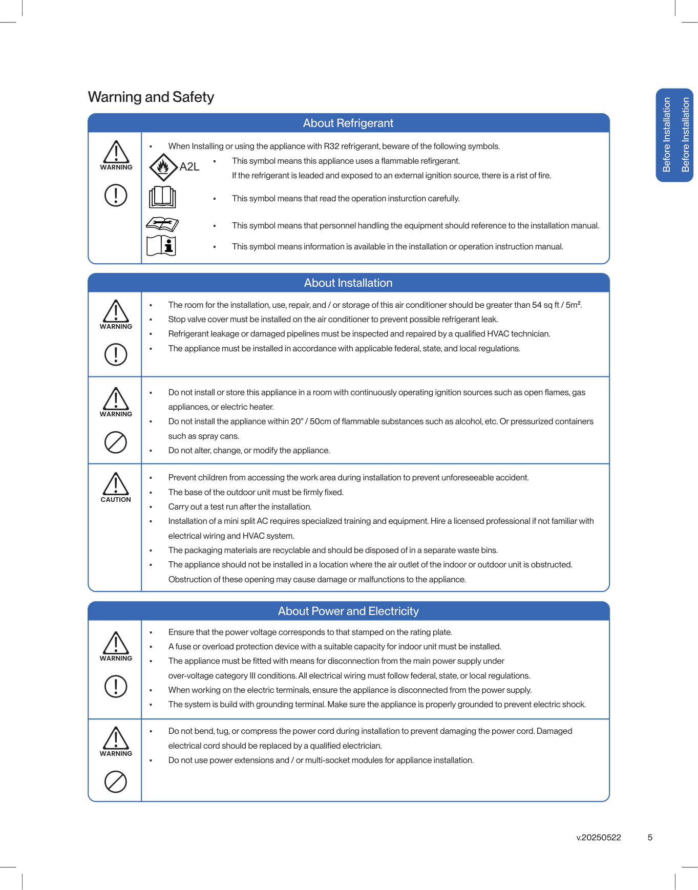
5 v.20250522 Before Installation Before Installation About Refrigerant • The room for the installation, use, repair, and / or storage of this air conditioner should be greater than 54 sq ft / 5m². • Stop valve cover must be installed on the air conditioner to prevent possible refrigerant leak. • • The appliance must be installed in accordance with applicable federal, state, and local regulations.
Warning
Warning and Safety About Installation About Power and Electricity • appliances, or electric heater. • such as spray cans. • Do not alter, change, or modify the appliance. • Prevent children from accessing the work area during installation to prevent unforeseeable accident. • • Carry out a test run after the installation. • Installation of a mini split AC requires specialized training and equipment. Hire a licensed professional if not familiar with electrical wiring and HVAC system. • The packaging materials are recyclable and should be disposed of in a separate waste bins. • The appliance should not be installed in a location where the air outlet of the indoor or outdoor unit is obstructed. Obstruction of these opening may cause damage or malfunctions to the appliance. • Ensure that the power voltage corresponds to that stamped on the rating plate. • A fuse or overload protection device with a suitable capacity for indoor unit must be installed. •over-voltage category III conditions. All electrical wiring must follow federal, state, or local regulations. • When working on the electric terminals, ensure the appliance is disconnected from the power supply. • The system is build with grounding terminal. Make sure the appliance is properly grounded to prevent electric shock. • Do not bend, tug, or compress the power cord during installation to prevent damaging the power cord. Damaged • Do not use power extensions and / or multi-socket modules for appliance installation.
Warning
Warning
Warning
Caution
Warning
• When Installing or using the appliance with R32 refrigerant, beware of the following symbols. •• This symbol means that read the operation insturction carefully. • This symbol means that personnel handling the equipment should reference to the installation manual. • This symbol means information is available in the installation or operation instruction manual.
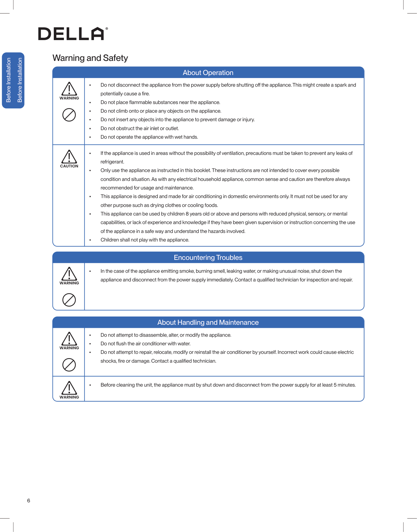
6 Warning and Safety About Operation About Handling and Maintenance Encountering Troubles • • • Do not climb onto or place any objects on the appliance. • Do not insert any objects into the appliance to prevent damage or injury. • Do not obstruct the air inlet or outlet. • Do not operate the appliance with wet hands. • Do not attempt to disassemble, alter, or modify the appliance. • • Do not attempt to repair, relocate, modify or reinstall the air conditioner by yourself. Incorrect work could cause electric • In the case of the appliance emitting smoke, burning smell, leaking water, or making unusual noise, shut down the • If the appliance is used in areas without the possibility of ventilation, precautions must be taken to prevent any leaks of refrigerant. • Only use the appliance as instructed in this booklet. These instructions are not intended to cover every possible condition and situation. As with any electrical household appliance, common sense and caution are therefore always recommended for usage and maintenance. • This appliance is designed and made for air conditioning in domestic environments only. It must not be used for any other purpose such as drying clothes or cooling foods. • This appliance can be used by children 8 years old or above and persons with reduced physical, sensory, or mental capabilities, or lack of experience and knowledge if they have been given supervision or instruction concerning the use of the appliance in a safe way and understand the hazards involved. • Children shall not play with the appliance. • Before cleaning the unit, the appliance must by shut down and disconnect from the power supply for at least 5 minutes.
Warning
Warning
Warning
Warning
Caution
Before Installation Before Installation
7 v.20250522 Before Installation Before Installation Name of Parts Air Outlet Air Deflector and Flap Air Filter Screen Front Panel Wiring Terminal with Wiring Diagram Drain Hose Refrigerant Pipe Emergency ON / OFF Switch Indoor Unit Outdoor Unit Refrigerant Valves Valve Cover Page 56 Page 58 Control Box with Wiring Diagram

8 Before Installation Before Installation Name of Parts Included Accessories (for each indoor unit) Mounting Plate 1x Bracket Template 1x • Screw Driver • Hole Saw Ø2.75" / Ø70mm • Refrigerant Leak Detector / Liquid Leak Detector • Allen Wrench • Spanner • Torque Wrench • Measuring Tape • Spirit Level • Stud Finder • Thermometer • Vacuum Pump • Dry Wall Anchors / Molly Bolts • Wood Screws • Floor Mounting Base Kit / Wall Mount Kit • Micron Gauge / AC manifold Gauge • Copper Pipe Bender / Spring Bender • Caulk • Ø25mm Drainage Joint • Ø2.5" / Ø65mm Wall Sleeve • Tubing Cutter* • Pipe Reamer* • Tubing Flaring Tool* • Wire cutter* NOTE: Tools marked with * are needed for shortening the refrigerant pipe and / or electrical wire to the exact desired length. Tools Needed (Not included) Communication Cable 1x Wall Cover 1x Plasticine Putty 1x Refrigerant Pipe Narrow 1x Thick 1x Drain Hose 1x Insulation Wrap 1x Remote Control & Holder 1x Battery 2x Rubber Foot Pad 4x Drainage Joint 1x
9 v.20250522 Before Installation Before Installation
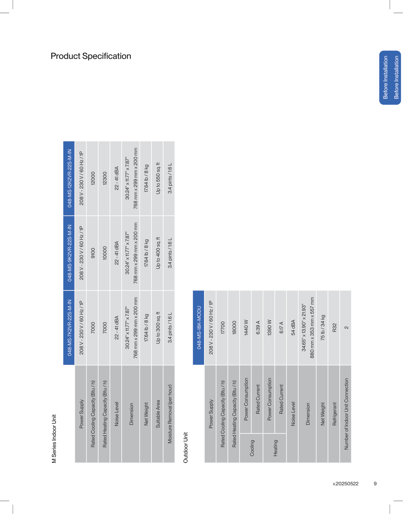
048-Ms-7K2Vr-22S-M-In
048-Ms-9K2Vr-22S-M-In
048-Ms-12K2Vr-22S-M-In
Power Supply 208 V - 230 V / 60 Hz / 1P 208 V - 230 V / 60 Hz / 1P 208 V - 230 V / 60 Hz / 1P Rated Cooling Capacity (Btu / h) 7000 9100 12000 Rated Heating Capacity (Btu / h) 7000 10000 12300 Noise Level 22 - 41 dBA 22 - 41 dBA 22 - 41 dBA Dimension 30.24" x 11.77" x 7.87" 768 mm x 299 mm x 200 mm 30.24" x 11.77" x 7.87" 768 mm x 299 mm x 200 mm 30.24" x 11.77" x 7.87" 768 mm x 299 mm x 200 mm Net Weight 17.64 lb / 8 kg 17.64 lb / 8 kg 17.64 lb / 8 kg Suitable Area Up to 300 sq. ft Up to 400 sq. ft Up to 550 sq. ft Moisture Removal (per hour) 3.4 pints / 1.6 L 3.4 pints / 1.6 L 3.4 pints / 1.6 L048-Ms-18K-Modu
Power Supply 208 V - 230 V / 60 Hz / 1P Rated Cooling Capacity (Btu / h) 17700 Rated Heating Capacity (Btu / h) 18000 Cooling Power Consumption1440 W
Rated Current6.39 A
Heating Power Consumption1390 W
Rated Current6.17 A
Noise Level 54 dBA Dimension 34.65" x 13.90" x 21.93" 880 mm x 353 mm x 557 mm Net Weight 75 lb / 34 kg RefrigerantR32
Number of Indoor Unit Connection 2 M Series Indoor Unit Outdoor Unit
10 Installation Installation Installation Preview 1 2 3 4 5 ≥ 7.9" / 20 cm ≥ 5.1" / 13 cm ≥ 5.1" / 13 cm ≥ 79" / 200 cm ≥ 11.8" / 30 cm ≥ 11.8" / 30 cm ≥ 19.7" / 50 cm ≥ 19.7" / 50 cm Choose the installation location -00- Mount the indoor unit -00- Placing the outdoor unit -00- Vacuum Pumping -00- Finishing -00- Check List -00- Test Run -00- Connection between indoor and outdoor unit • Connect the refrigerant pipes -00- • Connect the electrical wires -00- Indoor unit connection • Connect the drain hose to the indoor unit -00- • Pass the electrical wire into the indoor unit -00- Drill wall hole and Install mounting plate -00- 6 7 8 9 10 Standard Length 16.4 ft / 5 m Max. Distance 82 ft / 25 m Max. Elevation 49 ft / 15 m Page 12 Page 15 Page 16 Page 17 Page 13-14 Page 25 Page 34 Page 35 Page 36 Page 18-19 Page 22-23 Page 30-33 ≥ 98" / 250 cm (From the unit to the ground)
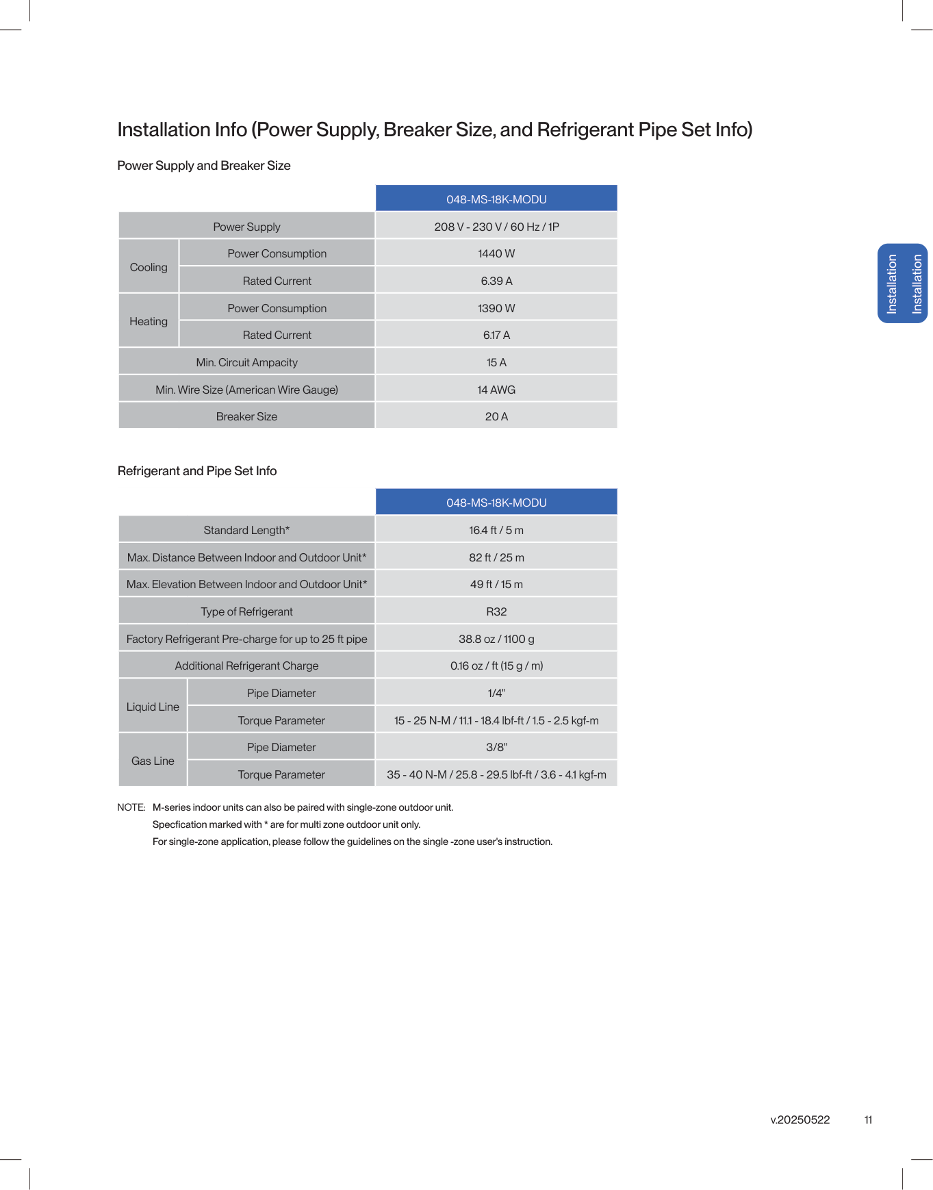
11 v.20250522 Installation Installation Installation Info (Power Supply, Breaker Size, and Refrigerant Pipe Set Info) Power Supply and Breaker Size
048-Ms-18K-Modu
Power Supply 208 V - 230 V / 60 Hz / 1P Cooling Power Consumption1440 W
Rated Current6.39 A
Heating Power Consumption1390 W
Rated Current6.17 A
Min. Circuit Ampacity15 A
Min. Wire Size (American Wire Gauge)14 Awg
Breaker Size20 A
Refrigerant and Pipe Set Info048-Ms-18K-Modu
Standard Length* 16.4 ft / 5 m Max. Distance Between Indoor and Outdoor Unit* 82 ft / 25 m Max. Elevation Between Indoor and Outdoor Unit* 49 ft / 15 m Type of RefrigerantR32
Factory Refrigerant Pre-charge for up to 25 ft pipe 38.8 oz / 1100 g Additional Refrigerant Charge 0.16 oz / ft (15 g / m) Liquid Line Pipe Diameter 1/4" Torque Parameter 15 - 25 N-M / 11.1 - 18.4 lbf-ft / 1.5 - 2.5 kgf-m Gas Line Pipe Diameter 3/8" Torque Parameter 35 - 40 N-M / 25.8 - 29.5 lbf-ft / 3.6 - 4.1 kgf-m NOTE: M-series indoor units can also be paired with single-zone outdoor unit. For single-zone application, please follow the guidelines on the single -zone user's instruction.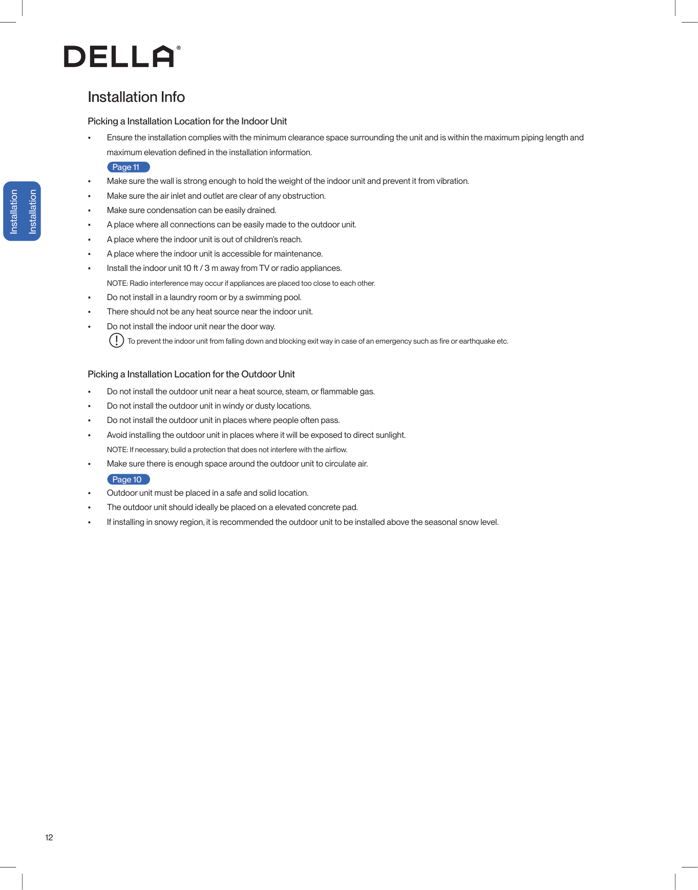
12 Installation Installation Installation Info Picking a Installation Location for the Indoor Unit Picking a Installation Location for the Outdoor Unit • Ensure the installation complies with the minimum clearance space surrounding the unit and is within the maximum piping length and maximum elevation defined in the installation information. -00- • Make sure the wall is strong enough to hold the weight of the indoor unit and prevent it from vibration. • Make sure the air inlet and outlet are clear of any obstruction. • Make sure condensation can be easily drained. • A place where all connections can be easily made to the outdoor unit. • A place where the indoor unit is out of children’s reach. • A place where the indoor unit is accessible for maintenance. • Install the indoor unit 10 ft / 3 m away from TV or radio appliances. NOTE: Radio interference may occur if appliances are placed too close to each other. • Do not install in a laundry room or by a swimming pool. • There should not be any heat source near the indoor unit. • Do not install the indoor unit near the door way. To prevent the indoor unit from falling down and blocking exit way in case of an emergency such as fire or earthquake etc. • Do not install the outdoor unit near a heat source, steam, or flammable gas. • Do not install the outdoor unit in windy or dusty locations. • Do not install the outdoor unit in places where people often pass. • Avoid installing the outdoor unit in places where it will be exposed to direct sunlight. NOTE: If necessary, build a protection that does not interfere with the airflow. • Make sure there is enough space around the outdoor unit to circulate air. -00- • Outdoor unit must be placed in a safe and solid location. • The outdoor unit should ideally be placed on a elevated concrete pad. • If installing in snowy region, it is recommended the outdoor unit to be installed above the seasonal snow level. Page 11 Page 10
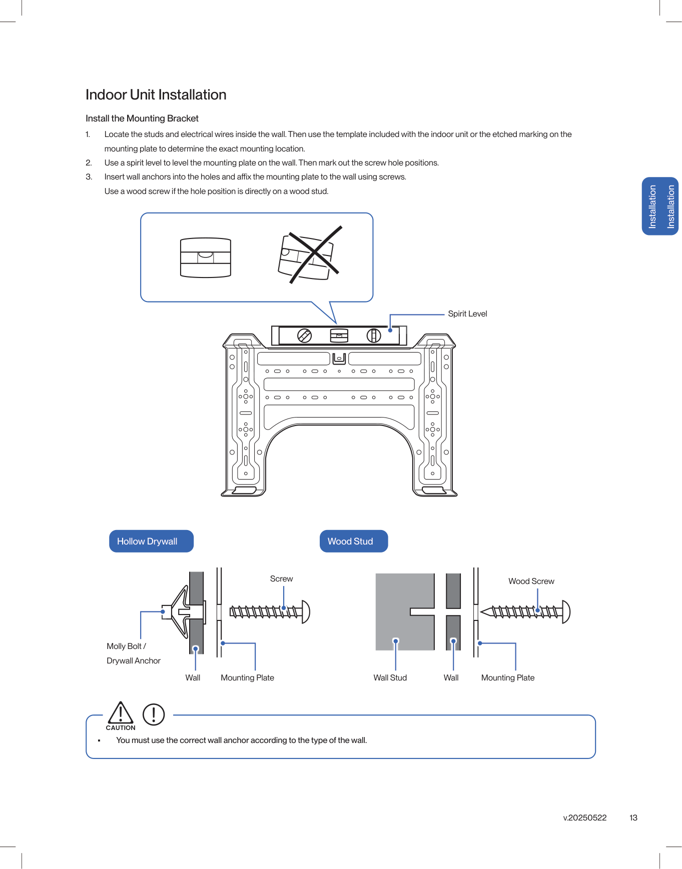
13 v.20250522 Installation Installation Indoor Unit Installation Install the Mounting Bracket • You must use the correct wall anchor according to the type of the wall.
Caution
Hollow Drywall Wood Stud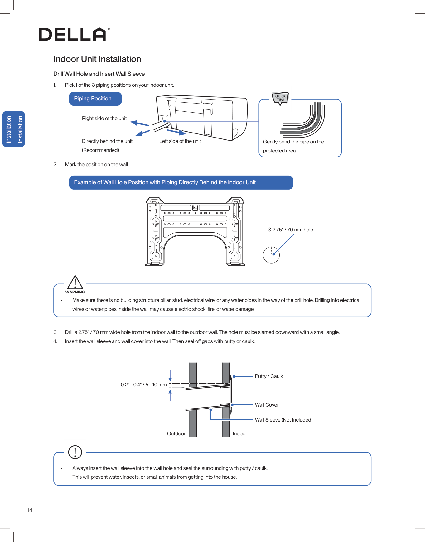
14 Installation Installation
Warning
Ø 2.75" / 70 mm hole
15 v.20250522 Installation Installation • Drain hose must be slanted downward and leave a small gap between the ground and the hose. • Avoid having bends or dents on the drain hose. • Do not leave the end of the hose into drainage gutter. Indoor Unit Installation Connect the Indoor Unit Drain Hose Drain Hose Installation Drainage Ports

16 Installation Installation Electric Cable Terminal Block Screw Indoor Unit Installation Pass Electrical Cable Through the Indoor Unit Bundle the Indoor Unit Refrigerant Pipes, Hose, and Cable
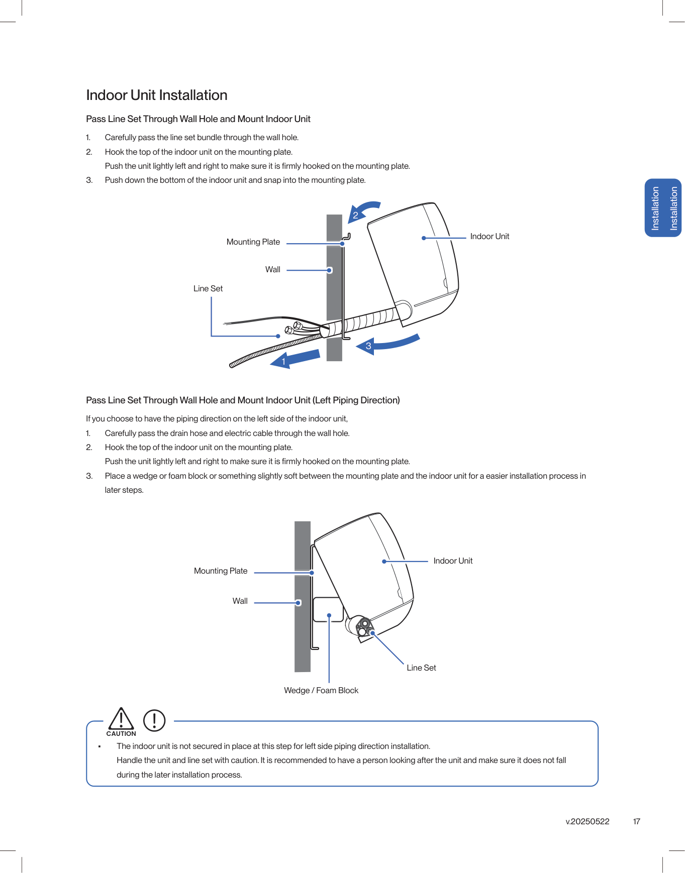
17 v.20250522 Installation Installation Line Set Line Set Wall Wall Mounting Plate Mounting Plate Indoor Unit Wedge / Foam Block Indoor Unit Installation Pass Line Set Through Wall Hole and Mount Indoor Unit Pass Line Set Through Wall Hole and Mount Indoor Unit (Left Piping Direction)
Caution
1 2 3 Indoor Unit
18 Installation Installation
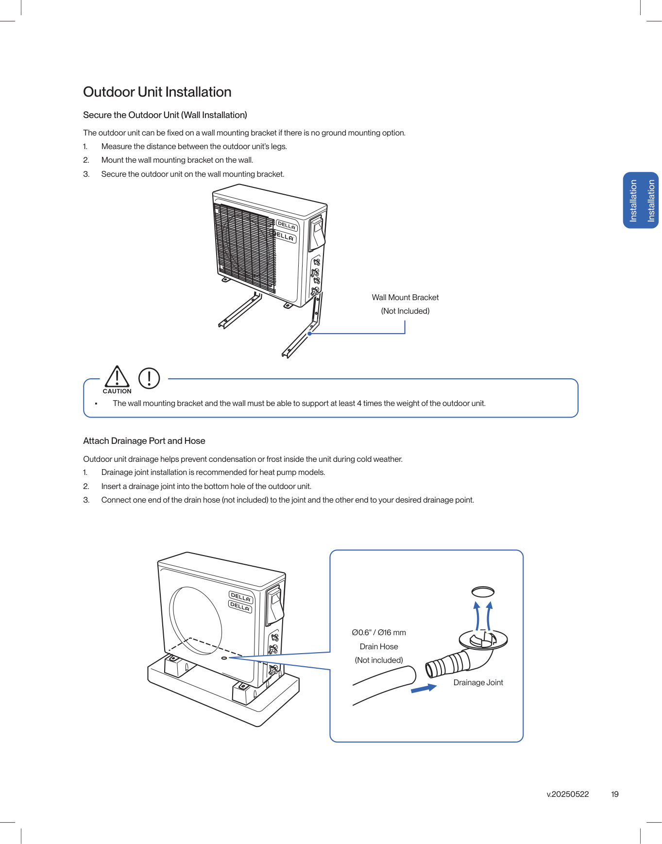
19 v.20250522 Installation Installation Outdoor Unit Installation Secure the Outdoor Unit (Wall Installation)
Caution
Drainage Joint Ø0.6" / Ø16 mm Drain Hose (Not included)
20
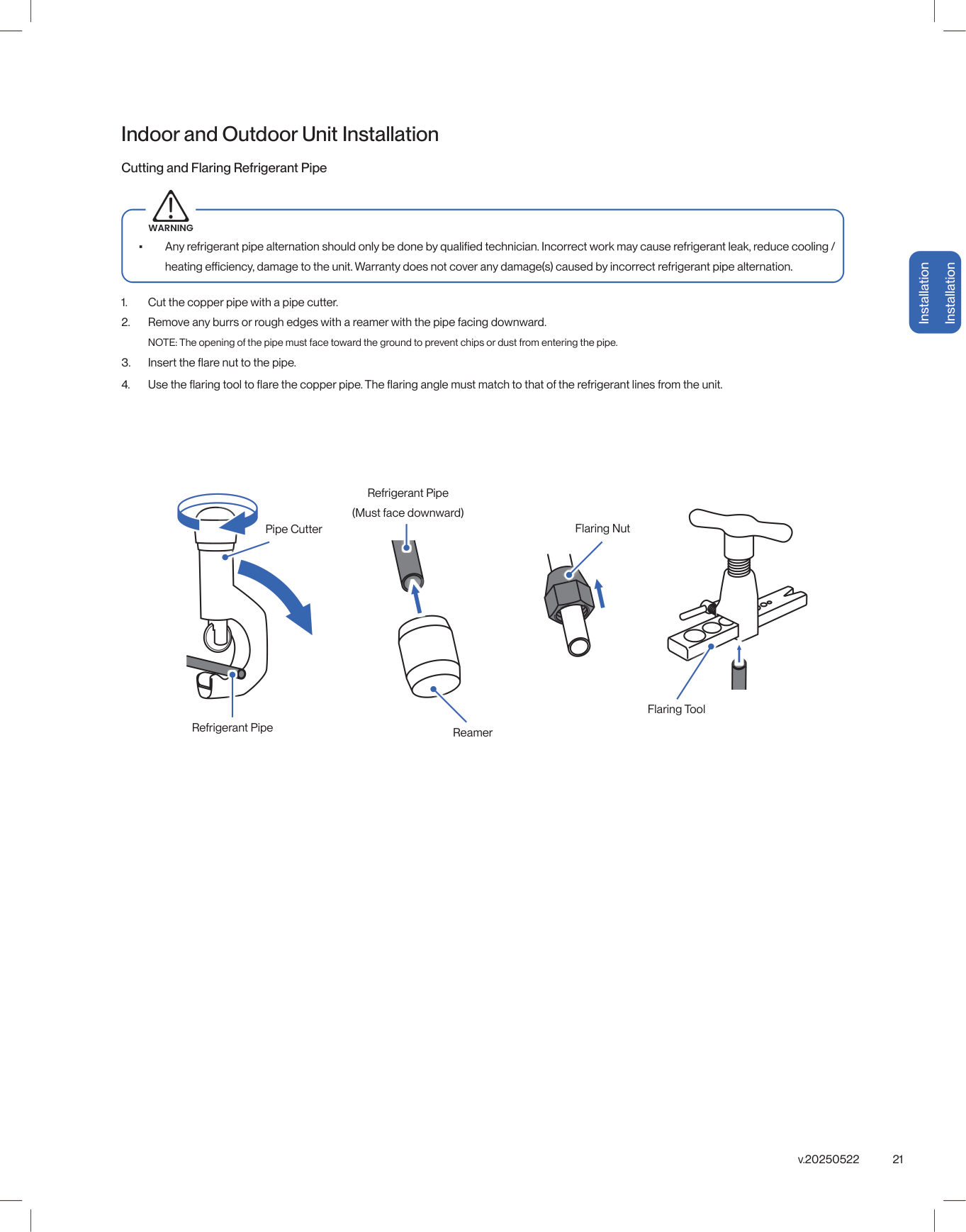
21 v.20250522 Cutting and Flaring Refrigerant Pipe
Warning
Installation Installation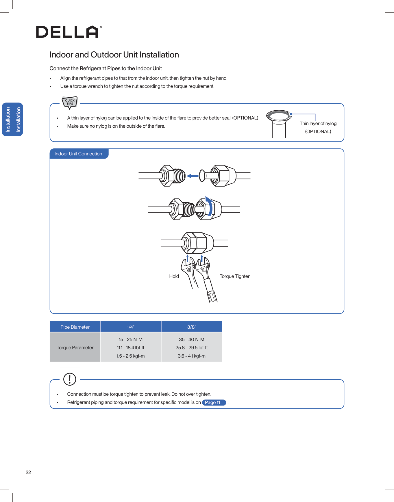
22 Installation Installation Indoor and Outdoor Unit Installation • Align the refrigerant pipes to that from the indoor unit, then tighten the nut by hand. • Use a torque wrench to tighten the nut according to the torque requirement. • • Thin layer of nylog
(Optional)
Pipe Diameter 1/4" 3/8” Torque Parameter15 - 25 N-M
11.1 - 18.4 lbf-ft 1.5 - 2.5 kgf-m35 - 40 N-M
25.8 - 29.5 lbf-ft 3.6 - 4.1 kgf-m • Connection must be torque tighten to prevent leak. Do not over tighten. • Connect the Refrigerant Pipes to the Indoor Unit Page 11 Hold Torque Tighten Indoor Unit Connection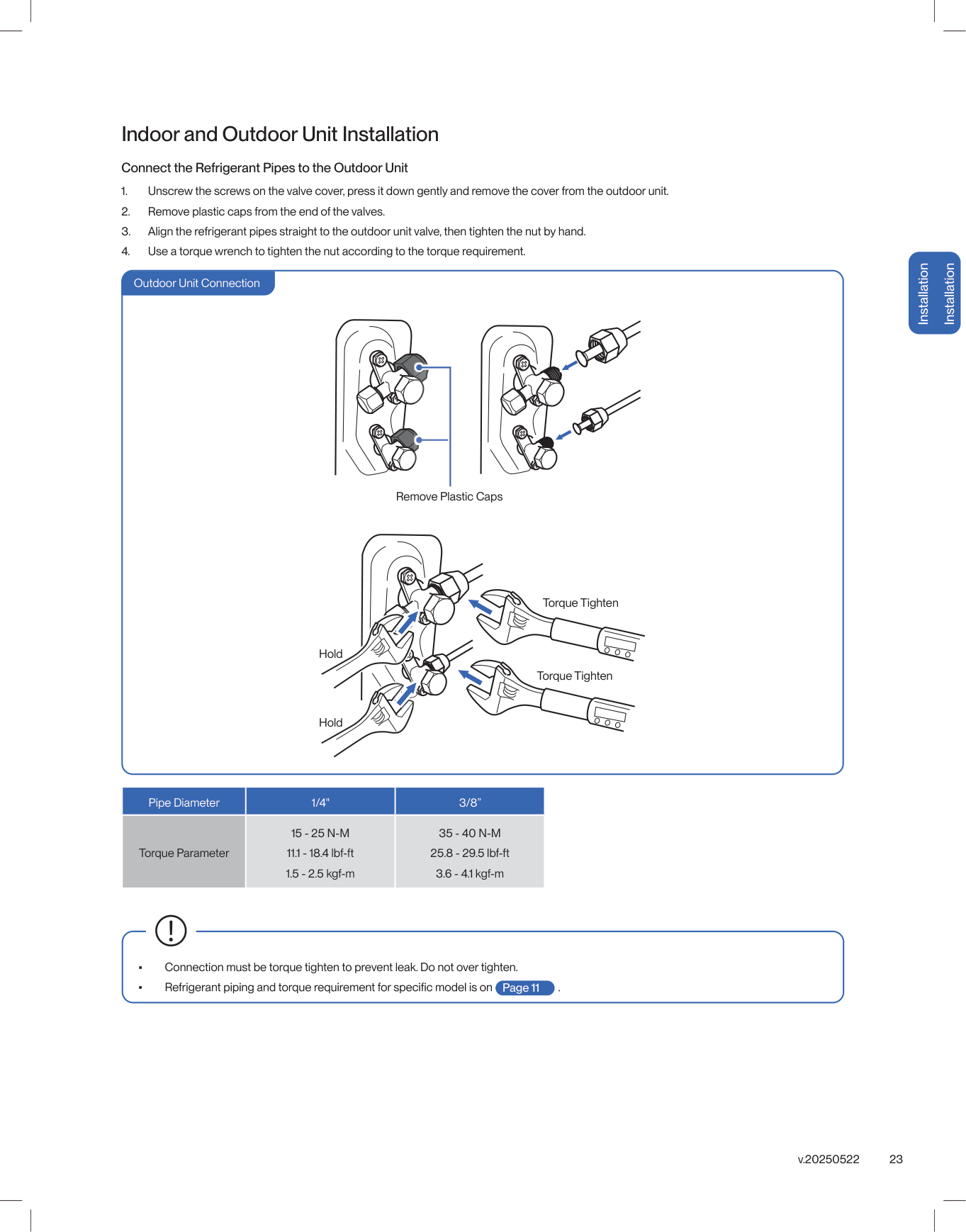
23 v.20250522 Installation Installation Indoor and Outdoor Unit Installation Connect the Refrigerant Pipes to the Outdoor Unit
15 - 25 N-M
11.1 - 18.4 lbf-ft 1.5 - 2.5 kgf-m35 - 40 N-M
25.8 - 29.5 lbf-ft 3.6 - 4.1 kgf-m • Connection must be torque tighten to prevent leak. Do not over tighten. • Outdoor Unit Connection Page 11
24 Installation Installation Indoor and Outdoor Unit Installation Outdoor Unit Knockouts for Electrical Wire
25 v.20250522 Installation Installation
L1(L)L 2(N)
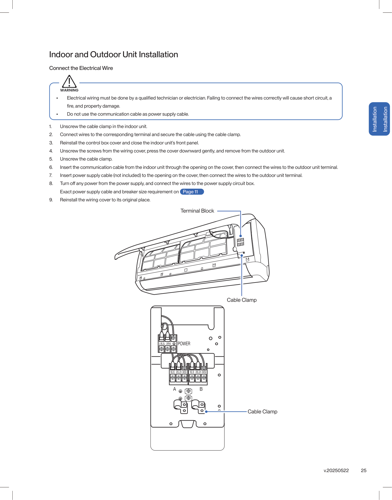
Indoor and Outdoor Unit Installation Connect the Electrical WireWarning
Page 11 Terminal Block Cable Clamp Cable Clamp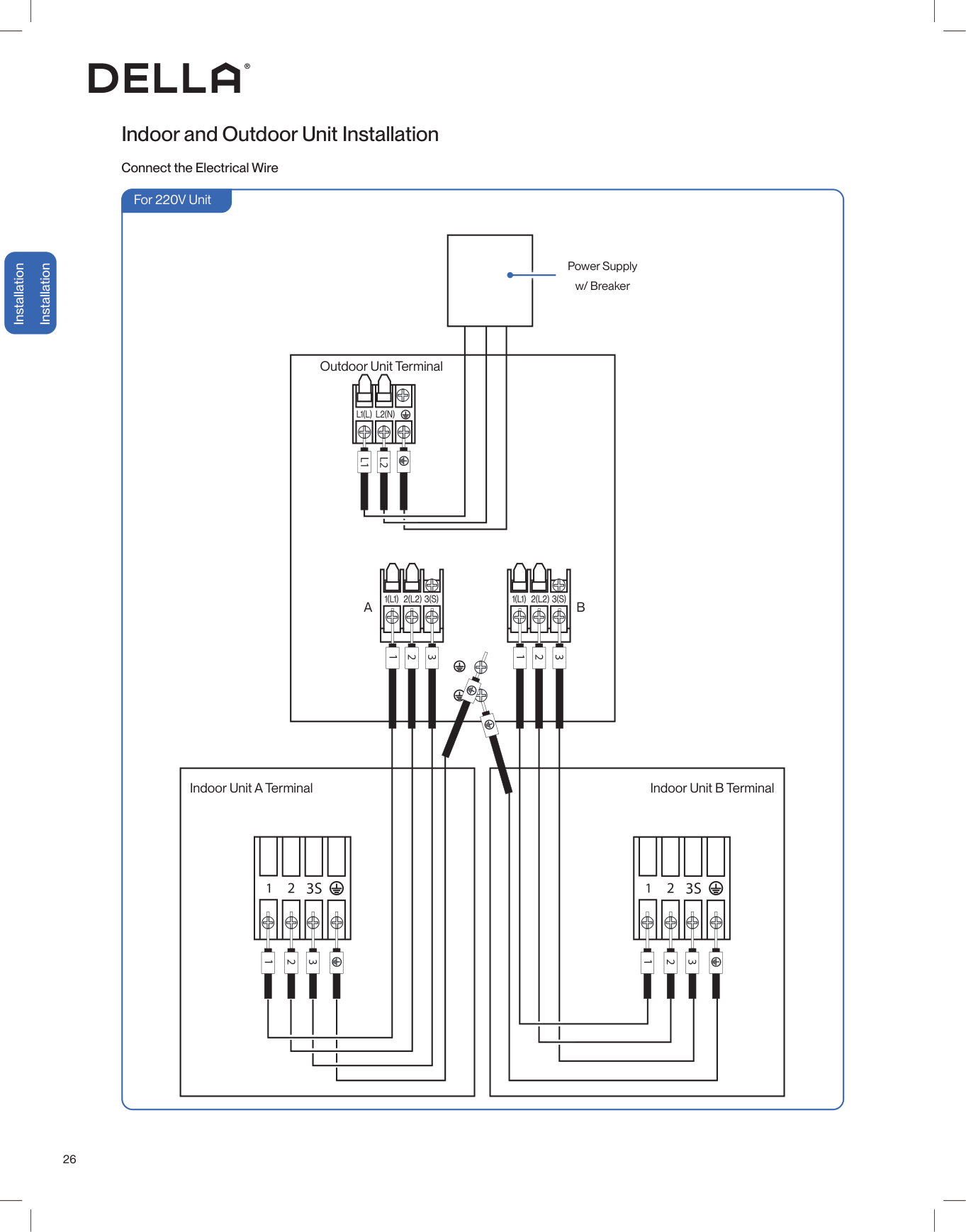
26 Installation Installation Indoor and Outdoor Unit Installation Connect the Electrical Wire For 220V Unit Outdoor Unit Terminal Indoor Unit A Terminal Indoor Unit B Terminal
A
B
Power Supply w/ Breaker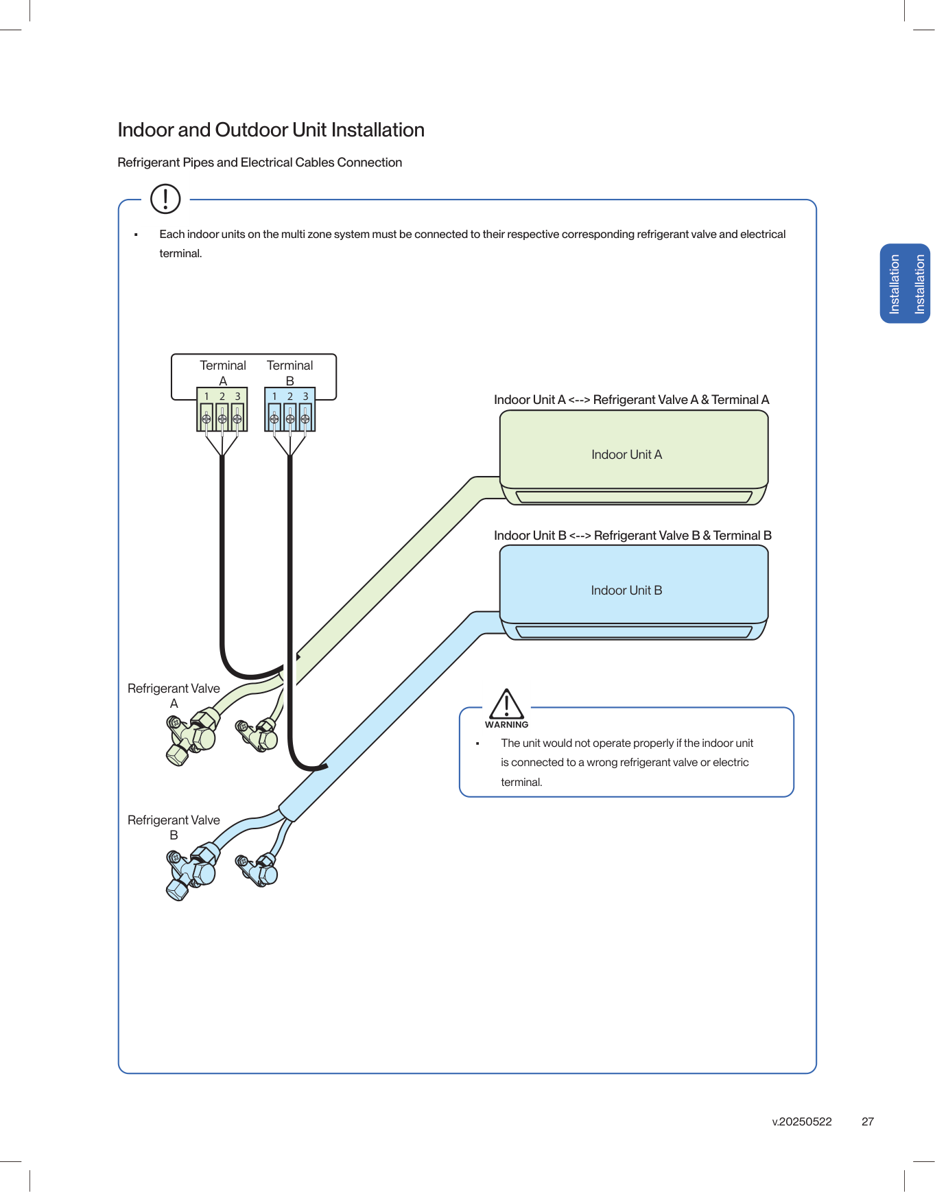
27 v.20250522 Installation Installation Indoor and Outdoor Unit Installation • Each indoor units on the multi zone system must be connected to their respective corresponding refrigerant valve and electrical terminal. Refrigerant Pipes and Electrical Cables Connection Terminal
A
TerminalB
Refrigerant ValveA
Refrigerant ValveB
Indoor Unit A <--> Refrigerant Valve A & Terminal A Indoor Unit B <--> Refrigerant Valve B & Terminal B Indoor Unit A Indoor Unit B • The unit would not operate properly if the indoor unit is connected to a wrong refrigerant valve or electric terminal.Warning
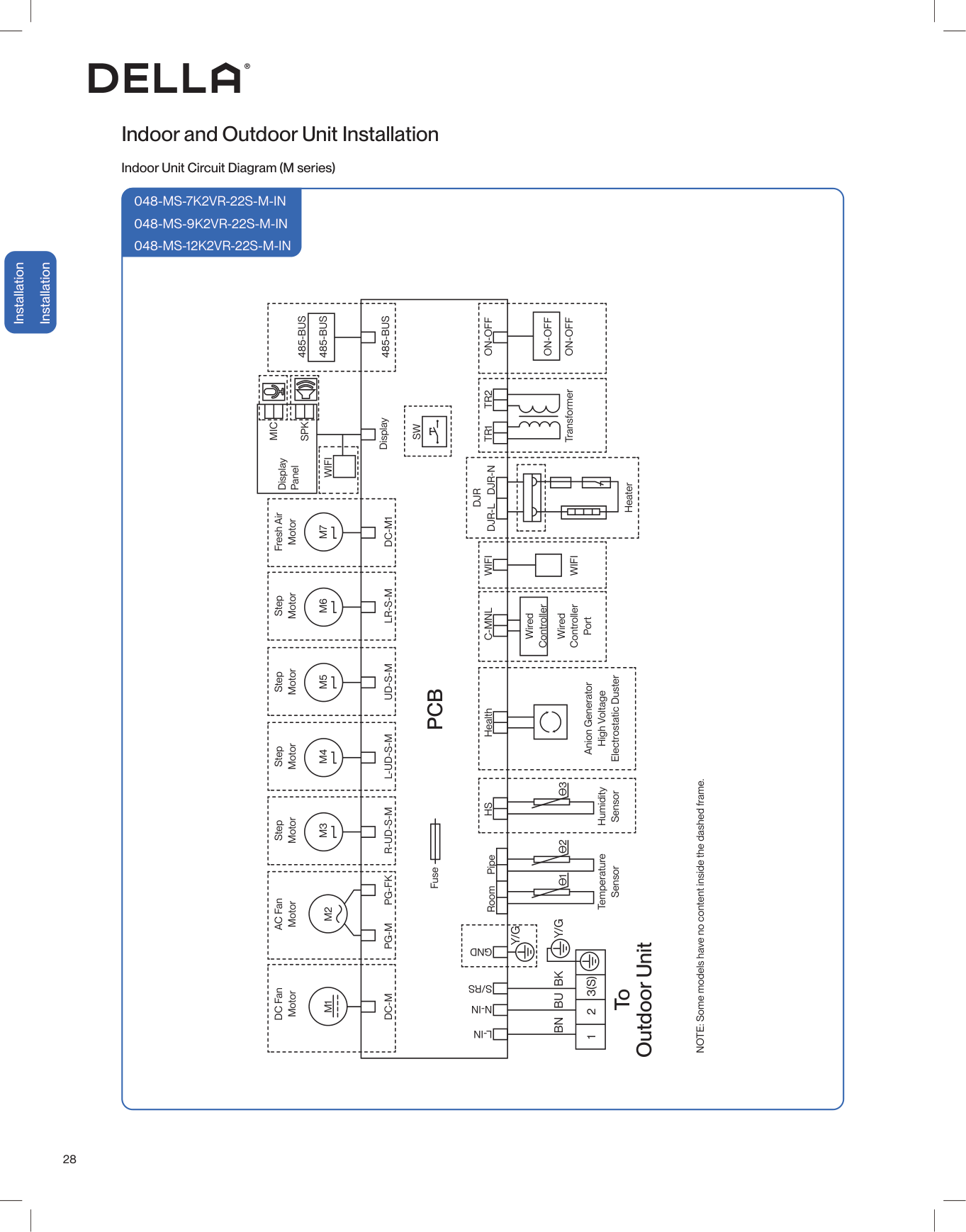
28 Installation Installation Indoor and Outdoor Unit Installation Indoor Unit Circuit Diagram (M series)
048-Ms-7K2Vr-22S-M-In
048-Ms-9K2Vr-22S-M-In
048-Ms-12K2Vr-22S-M-In
Pcb
To Outdoor Unit FuseL-In
N-In
S/Rs
Gnd
Ө
Ө
Ө
1 2 33(S)
2 1Bk
Y/G
Y/G
Bu
Bn
Temperature Sensor Humidity Sensor Anion Generator High Voltage Electrostatic Duster NOTE: Some models have no content inside the dashed frame. Room PipeHs
HealthC-Mnl
Wifi
Wifi
Dc-M1
Lr-S-M
Ud-S-M
L-Ud-S-M
R-Ud-S-M
Pg-Fk
Pg-M
Dc-M
M7
M6
M5
M4
M3
M2
M1
Fresh Air Motor Step Motor Step Motor Step Motor Step Motor AC Fan Motor DC Fan Motor Display PanelDjr-L
Djr-N
Djr
Heater TransformerOn-Off
On-Off
On-Off
Tr1
Tr2
Sw
485-Bus
DisplayMic
Spk
485-Bus
485-Bus
Wifi
Wired Controller Wired Controller Port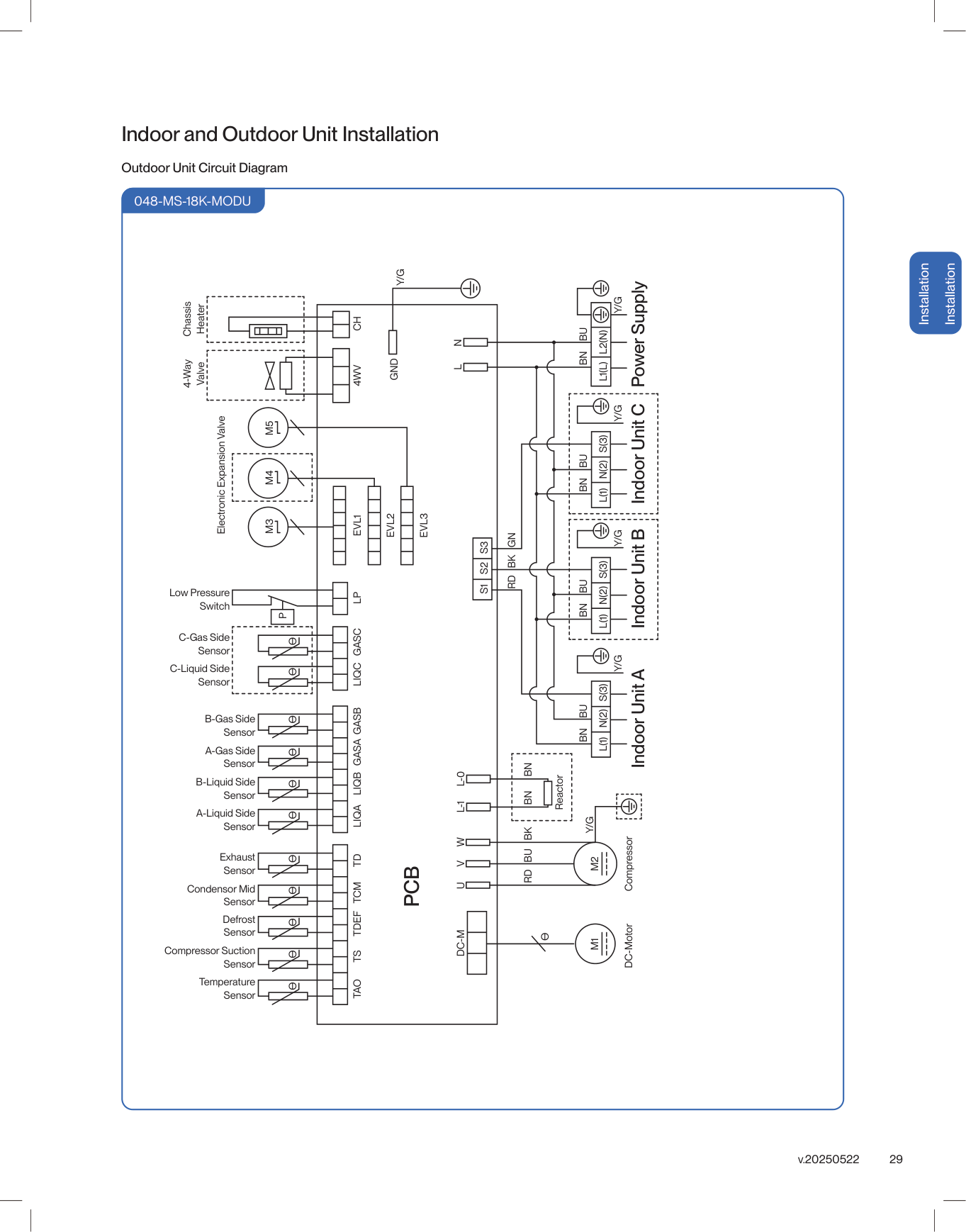
29 v.20250522 Installation Installation Indoor and Outdoor Unit Installation Outdoor Unit Circuit Diagram
048-Ms-18K-Modu
Pcb
Tao
Temperature Sensor Compressor Suction Sensor Defrost Sensor Condensor Mid Sensor Exhaust Sensor A-Liquid Side Sensor A-Gas Side Sensor C-Gas Side Sensor Low Pressure Switch Electronic Expansion Valve 4-Way Valve Chassis Heater B-Liquid Side Sensor C-Liquid Side Sensor B-Gas Side SensorTs
Tdef
Liqa
Gasa
Gasc
Lp
Evl1
4Wv
Ch
Evl2
Evl3
Gasb
Liqb
Liqc
Tcm
Td
L-1
W
N
V
L
U
Dc-M
M3
M4
M5
DC-Motor Compressor ReactorM1
M2
L-0
Gnd
L(1)
L(1)
L(1)
L1(L)
S1
S2
S3
L2(N)
N(2)
N(2)
N(2)
S(3)
S(3)
S(3)
P
Rd Bu Bk
Bn
Bn
Bn
Bn
Bn
Bn
Bu
Bu
Bu
Bu
Rd Bk Gn
Y/G
Y/G
Y/G
Y/G
Y/G
Y/G
Ө
Indoor Unit A Indoor Unit B Indoor Unit C Power SupplyӨ
Ө
Ө
Ө
Ө
Ө
Ө
Ө
Ө
Ө
Ө
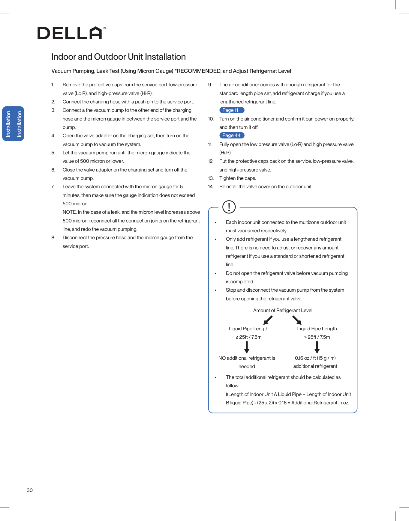
30 Indoor and Outdoor Unit Installation Vacuum Pumping, Leak Test (Using Micron Gauge) *RECOMMENDED, and Adjust Refrigernat Level

31 v.20250522 Indoor and Outdoor Unit Installation Charging Hose Vacuum Pump High Pressure Valve (Hi·R) Valve Adapter Low Pressure Valve (Lo·R) Micron Gauge Service Port Micron Micron Gauge Connection Installation Installation
32

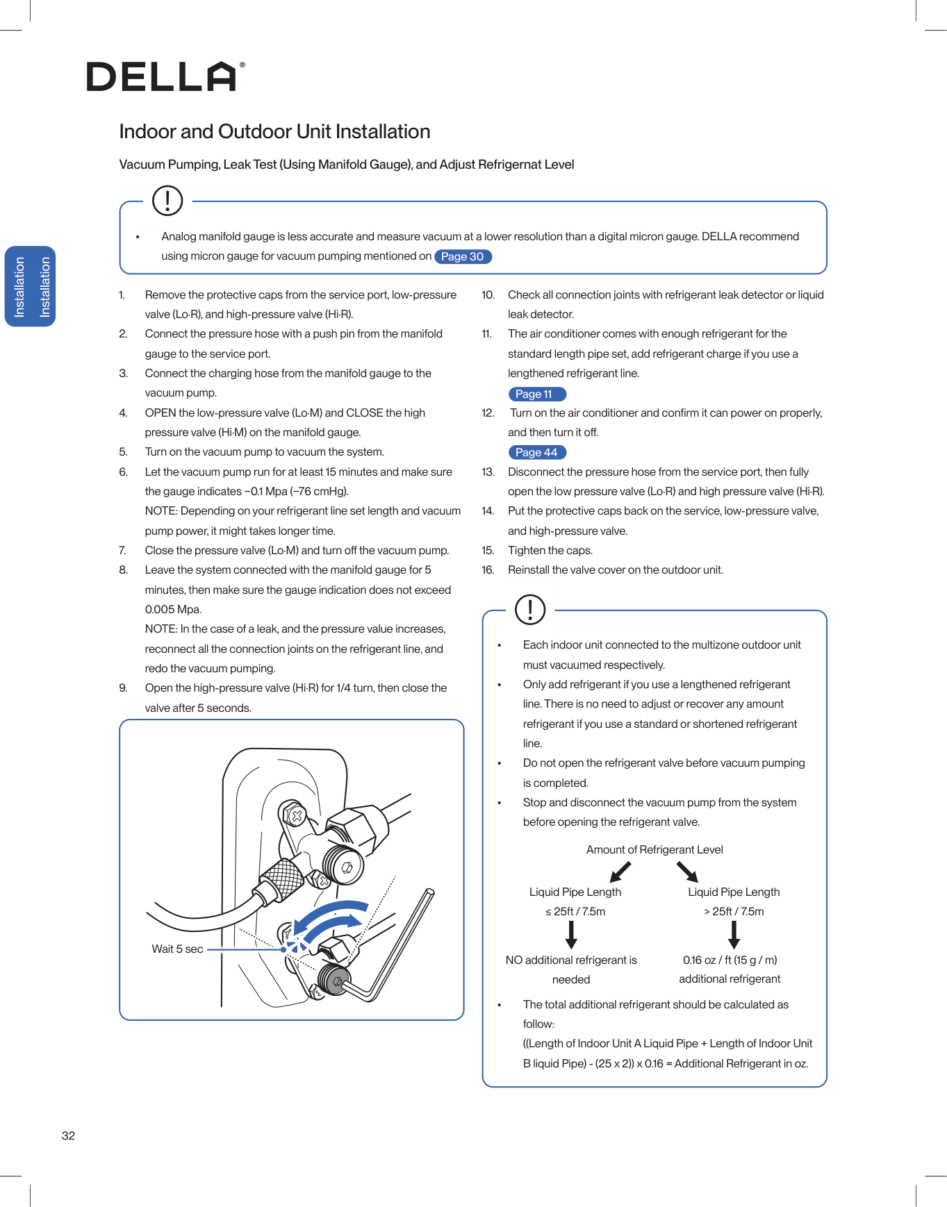
33 v.20250522 Indoor and Outdoor Unit Installation kg/cm² Pressure Hose Charging Hose Manifold Gauge High Pressure Valve (Hi·R) High Pressure Valve (Hi·M) Low Pressure Valve (Lo·R) Low Pressure Valve (Lo·M) Service Port Vacuum Pump Installation Installation Manifold Gauge Connection

34 Installation Installation Install a decorative line cover kit (not included) on the outdoor wall and over the line bundle to protect it from rain, sunlight, and other external elements. Make sure the indoor unit is firmly attached to the mounting bracket. Seal the wall penetration with sealant / putty / caulk etc. (Only putty is included in the package) to prevent water or insects from getting into the wall. • When wrapping and bundling the line set, avoid over tightening to prevent the insulating materials from over compression. • Make sure all connection joints are properly insulated. Line Set Insulation, Bundling, and Finishing Touch Refrigerant Pipes, drain hose, and electric cable must be properly arranged and bundled with insulation tape to maximize the unit’s efficiency and prevent condensation or water leak. Finishing Wrapping Tape Polyethylene Foam, hold in place with zip ties or tape
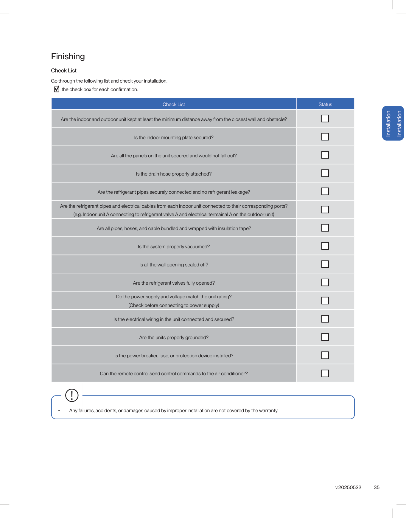
35 v.20250522 Finishing Check List Go through the following list and check your installation. Check List Status Are the indoor and outdoor unit kept at least the minimum distance away from the closest wall and obstacle? Is the indoor mounting plate secured? Are all the panels on the unit secured and would not fall out? Is the drain hose properly attached? Are the refrigerant pipes securely connected and no refrigerant leakage? Are the refrigerant pipes and electrical cables from each indoor unit connected to their corresponding ports? (e.g. Indoor unit A connecting to refrigerant valve A and electrical termainal A on the outdoor unit) Are all pipes, hoses, and cable bundled and wrapped with insulation tape? Is the system properly vacuumed? Are the refrigerant valves fully opened? Do the power supply and voltage match the unit rating? (Check before connecting to power supply) Is the electrical wiring in the unit connected and secured? Are the units properly grounded? Is the power breaker, fuse, or protection device installed? Can the remote control send control commands to the air conditioner? • Any failures, accidents, or damages caused by improper installation are not covered by the warranty. Installation Installation
36 Test Run After the installation, test run the mini split system and take sure it performs and works properly without water leak or abnormal noise. Finishing

37 v.20250522 Before Using Before Using Operation Tips Before Using Avoid placing TV, radio or large furniture under the air conditioner. Avoid putting plants or objects around the outdoor unit. Close windows and blinds. Avoid direct wind flow to people, pets, or plants. Follow cleaning and maintenance routine. DO NOT manually adjust the deflector and flaps. • It may block wind flow or interfere with the remote control. • It may lower the air conditioner efficiency or cause malfunction. • The air conditioner can cool or warm the area with better efficiency. • Expose to direct wind flow for extended period of time may have a negative impact on your health. • Regular cleaning and maintenance are needed for the best efficiency and prevent bad odor or water leak. • It may cause injury to the user and damages to the air conditioner.

38 Before Using Before Using Air Filter -00- Air Outlet Air Deflector and Flaps -00- Emergency ON / OFF Switch -00- Wi-Fi Module Front Panel NOTE: The graphical representation might have slight differences than the actual product. LED Indicator Function Lights up when the unit is turned on and operating Indicator for temperature, timer, and error codes Indoor Unit and Front Panel Before Using Display Page 58 Page 46 Page 56

39 v.20250522 Before Using Before Using Remote Control Holder Remote Control (Remote Control Holder)

41 v.20250515U Made to live with you, Della puts controls in your hands so that you can easily dail in a stress-free space that helps you feel more you. Just Right, Always.

42 Before Using Before Using Vicinity Sensor Button Let the air conditioner adjust temperature automatically according to the detected temperature around the remote control -00- Self Clean Button Enable the air conditioner to clean its internal parts -00- Display Indicate operating status, temperature or timer setting Mode Button Select operation mode -00- Power Button Turn ON / OFF the air conditioner -00- Fan Button Select fan speed -00- Quiet Button Enable the air conditioner to run in quiet mode -00- Sleep Button Enable the air conditioner to operate a pre-set program suited for sleep time -00- Increase / Decrease Button Adjust temperature / timer setting Air Flow Button Control deflector & flaps to direct air flow -00- Turbo Button Temporary boosting the air conditioner performance -00- ECO Button Enable the air conditioner to be more energy efficient -00- Display Button Turn ON / OFF the indoor unit display -00- Timer Button Enable ON / OFF timer setting -00- Remote Control Before Using Page 44 Page 46 Page 47 Page 48 Page 49 Page 50 Page 44 Page 45 Page 47 Page 48 Page 50 Page 51

43 v.20250522 Before Using Before Using Remote Control Before Using LED Indicator Function Signal Indicator Child Lock Indicate Set Temperature Indicate Room Temperature Low Battery Auto Mode Cool Mode Dehumidify Mode Heat Mode Fan Mode Indicate Temperature Value Temperature Unit Degree Fahrenheit / Celsius LED Indicator Function Horizontal & Vertical Air Flow Indicator Quiet Mode Fan Speed Turbo Mode Eco Mode Sleep Mode Timer Vicinity Sensor Mode Self Clean
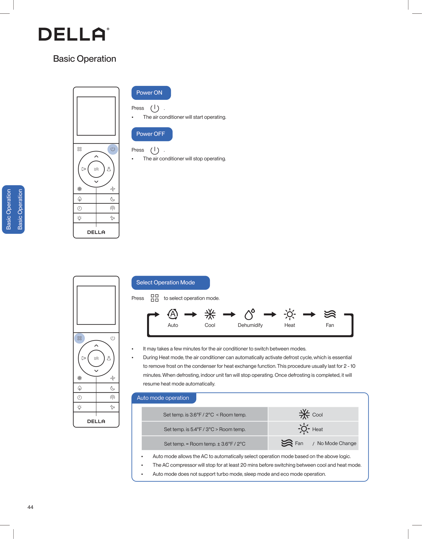
44 Basic Operation Press . • The air conditioner will start operating. Press . • The air conditioner will stop operating. Power ON Power OFF Basic Operation Basic Operation • It may takes a few minutes for the air conditioner to switch between modes. • During Heat mode, the air conditioner can automatically activate defrost cycle, which is essential to remove frost on the condenser for heat exchange function. This procedure usually last for 2 - 10 minutes. When defrosting, indoor unit fan will stop operating. Once defrosting is completed, it will resume heat mode automatically. Auto Cool Dehumidify Heat Fan Press to select operation mode. Select Operation Mode • Auto mode allows the AC to automatically select operation mode based on the above logic. • The AC compressor will stop for at least 20 mins before switching between cool and heat mode. • Auto mode does not support turbo mode, sleep mode and eco mode operation. Set temp. is 3.6°F / 2°C < Room temp. Set temp. is 5.4°F / 3°C > Room temp. Set temp. = Room temp. ± 3.6°F / 2°C / Cool Heat Fan No Mode Change Auto mode operation
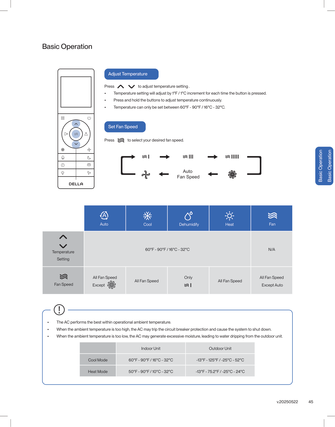
45 v.20250522 Basic Operation Adjust Temperature Set Fan Speed Press to adjust temperature setting . • Temperature setting will adjust by 1°F / 1°C increment for each time the button is pressed. • Press and hold the buttons to adjust temperature continuously. • Temperature can only be set between 60°F - 90°F / 16°C - 32°C. Press to select your desired fan speed.
60°F - 90°F / 16°C - 32°C
N/A
All Fan Speed All Fan Speed Only All Fan Speed All Fan Speed Auto Cool Dehumidify Temperature Setting Fan Speed Except Except Auto Heat Fan Basic Operation Basic Operation Indoor Unit Outdoor Unit Cool Mode60°F - 90°F / 16°C - 32°C
-13°F - 125°F / -25°C - 52°C
Heat Mode50°F - 90°F / 10°C - 32°C
-13°F - 75.2°F / -25°C - 24°C
• The AC performs the best within operational ambient temperature. • When the ambient temperature is too high, the AC may trip the circuit breaker protection and cause the system to shut down. • When the ambient temperature is too low, the AC may generate excessive moisture, leading to water dripping from the outdoor unit.
46 Basic Operation Adjust Air Flow Press to oscillate horizontal flaps. Press to oscillate vertical vanes . Press one more time. Press one more time. The flaps will stop at the position it was in when you pressed the button. The vanes will stop at the position it was in when you pressed the button. • When holding the horizontal flaps in place. It is recommended to hold the flaps in the up most position during cool mode. Vice versa, it is recommended to hold the flaps in the down most position during heat mode. • Cold air tends to sink. • Warm air tends to rise. Basic Operation Basic Operation

47 v.20250522 Advance Function Turbo Mode Using turbo mode can boost the air conditioner performance in a short amount of time. Press . • The air conditioner will operate in boosted fan speed. • Turbo mode is not available when the air conditioner is operating in auto mode or dehumidification mode. The air conditioner will operate at the minimum noise level under quiet mode. Press . • The air conditioner will operate in the lowest fan speed. • Quiet mode is not available when the air conditioner is operating in dehumidification mode. To stop turbo mode, press again or press / / . To stop quiet mode, press again or press / / . Quiet Mode Advance Function Advance Function
48 +
60°F - 90°F / 16°C - 32°C
Advance Function CoolEco
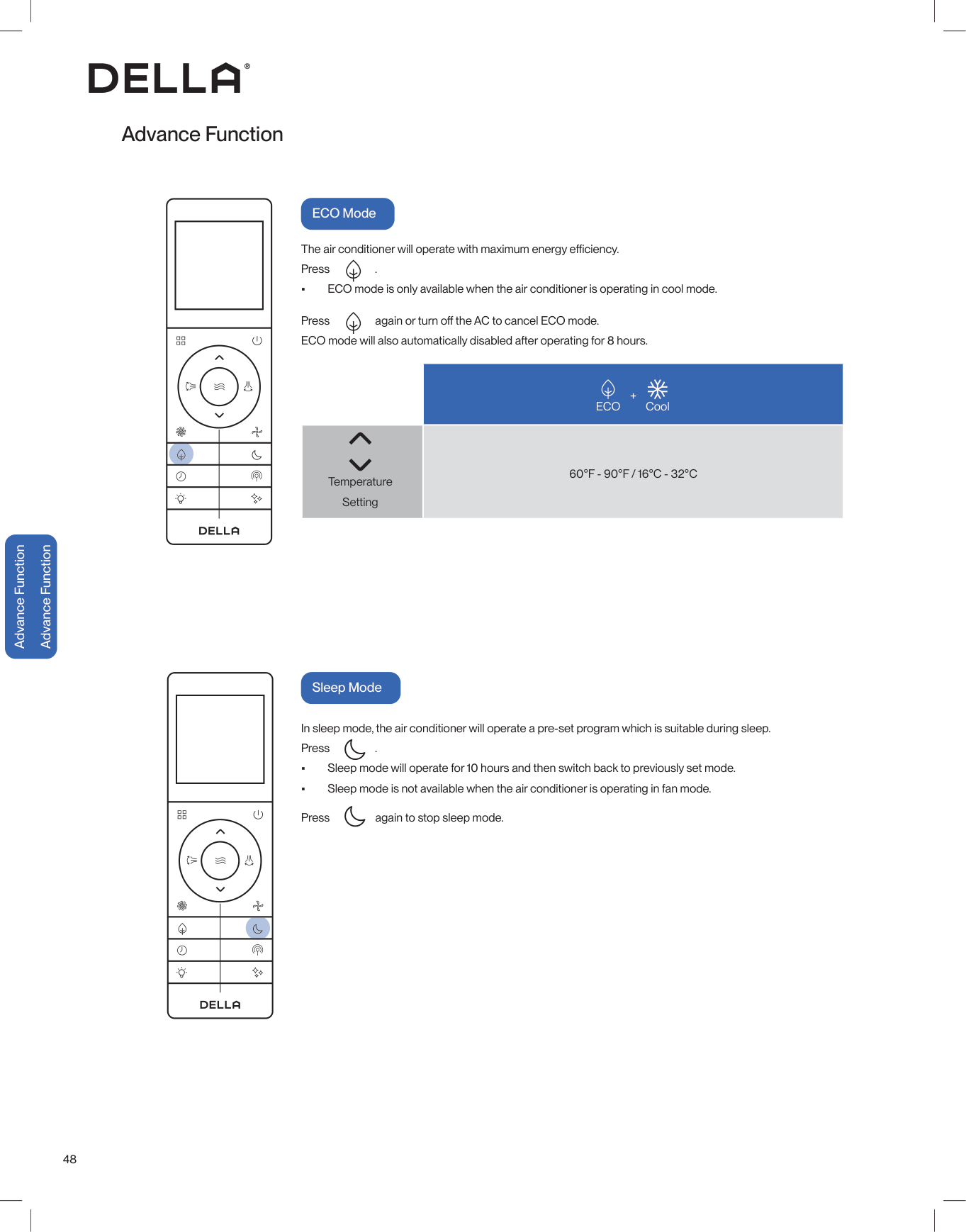
ECO Mode The air conditioner will operate with maximum energy efficiency. Press . • ECO mode is only available when the air conditioner is operating in cool mode. Press again or turn off the AC to cancel ECO mode. ECO mode will also automatically disabled after operating for 8 hours. Temperature Setting Advance Function Advance Function In sleep mode, the air conditioner will operate a pre-set program which is suitable during sleep. Press . • Sleep mode will operate for 10 hours and then switch back to previously set mode. • Sleep mode is not available when the air conditioner is operating in fan mode. Press again to stop sleep mode. Sleep Mode
49 v.20250522 • While entering the setting, make sure to press the button within 10 seconds after the previous button was pressed. otherwise, the entire process will reset and you will have to start over. •
Advance Function Timer Function (Shutdown Timer) Timer Function (Start-up Timer) Set a timer to automatically turn OFF the air conditioner. Press when the air conditioner is ON. Press to set the desired turn off time. Press to confirm the timer setting. Press to confirm the timer setting. Set a timer to automatically turn ON the air conditioner. Press when the air conditioner is OFF. Press to set the desired turn on time. Press , and to select your desired operation mode, temperature setting, and fan speed for when the air conditioner is turn ON. Press Timer default at 0.5 h Timer Set Edit timer setting Cancel timer Without pressing any button for 10 sec Press to confirm • Both the shutdown and start-up timer can be set between 0.5 - 24 hours. Advance Function Advance Function

50 Advance Function Vicinity Sensor Switch ON / OFF the LED display on the indoor unit front panel. Press to turn OFF the indoor unit display. • The display on the indoor unit will not lit up, and no indicator will be shown on the remote control. • The AC will still function normally and commandable using the remote control. Press again to turn ON the indoor unit display. Display ON / OFF Advance Function Advance Function Vicinity sensor function turns your remote control into a portable thermostat that automatically controls the unit to adjust the temperature of the room you are in. Press to activate vicinity sensor function. • The display panel will show your set temperature. • After setting your desire temperature, the display will flash for 5 seconds, and show the detected environment temperature. • In the case of the temperature detected by the remote control is greater than 122 °F / 50 °C, or short circuit, the system will determine it as a malfuction / error on the remote control and automatically disable vicinity sensor function within 30 seconds. Remote control detect its surrounding temperature every 3 minutes. Air conditioner would operate to match the detected temperature to the set temperature. NOTE: The remote control must be pointed towards the indoor unit to prevent lost of communication. Press again to stop vicinity sensor function.

51 v.20250522 Self cleaning function allows the air conditioner to clean the interior parts and helps carry away the accumulated dirt, bacteria, etc. from the indoor evaporator. Press when the air conditioner is OFF. • will display on the remote control display. • will display on the indoor unit display. • The self cleaning function will run for 30-50 minutes,. • If you enable self cleaning while the AC has a start-up timer set, The AC will start up once the self cleaning cycle is completed. • It is recommended to operate this function when the indoor ambient temperature is under 86°F / 30°C, and the outdoor ambient temperature is between 41°F - 86°F / 5°C - 30°C. • It is suggested to run the self cleaning function once every 3 months. • It is normal that the unit makes some noise during self cleaning process as plastic materials expand and contract with temperature change. • Press within 30 minutes of self cleaning function will terminate self cleaning. • Turning ON the AC during self cleaning operation will terminate self cleaning and forced the AC into normal operation. Advance Function Self Cleaning Child lock function will disable all input from the remote control until unlocked. Press and hold and for 3 seconds to activate child lock. • will display on the remote control display. Press and hold and for 3 seconds again to dectivate child lock. Child Lock Advance Function Advance Function
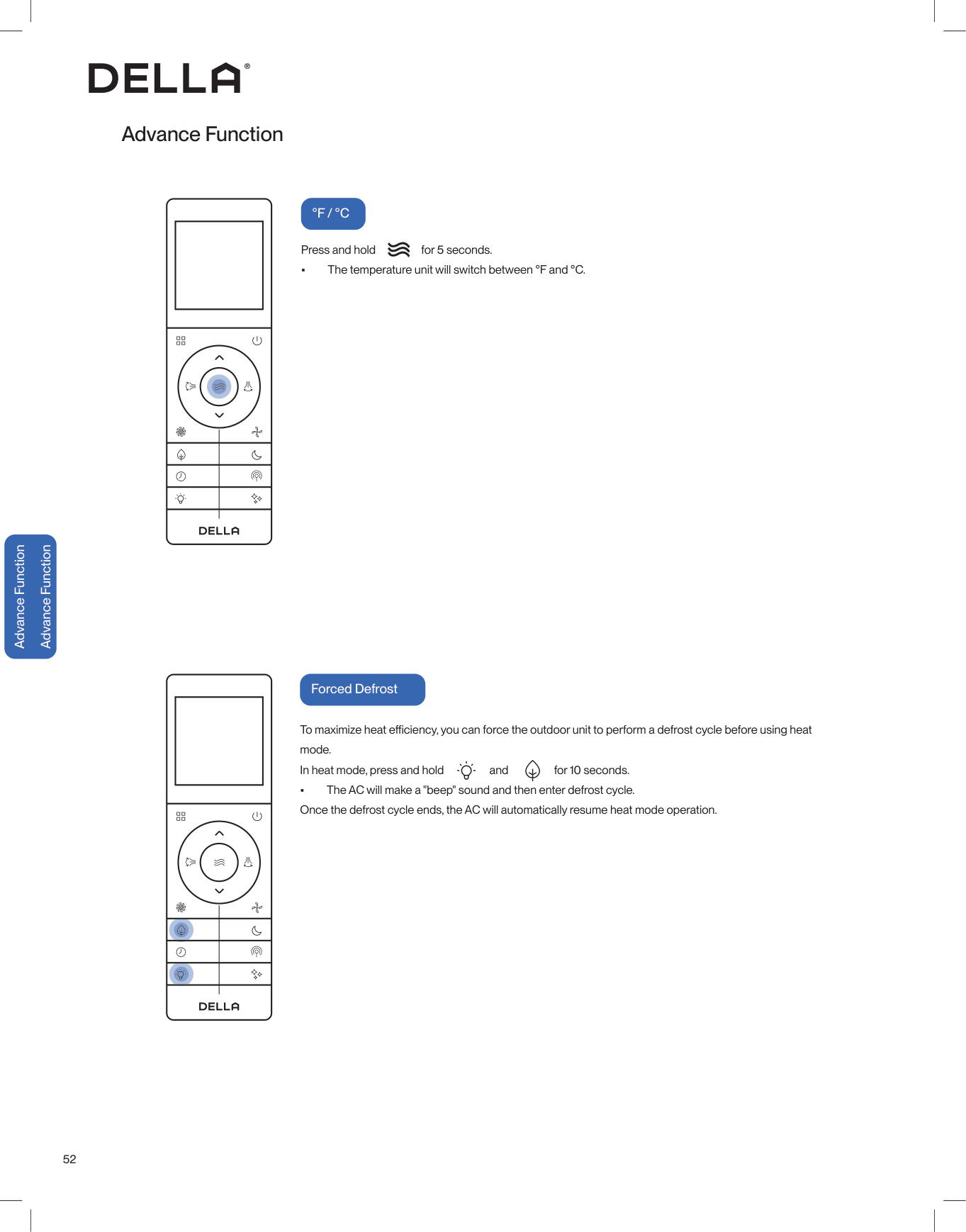
52 Press and hold for 5 seconds. • The temperature unit will switch between °F and °C. Advance Function
°F / °C
Advance Function Advance Function To maximize heat efficiency, you can force the outdoor unit to perform a defrost cycle before using heat mode. In heat mode, press and hold and for 10 seconds. • The AC will make a "beep" sound and then enter defrost cycle. Once the defrost cycle ends, the AC will automatically resume heat mode operation. Forced Defrost
53 v.20250522 Advance Function Advance Function Press 6 times within 3 seconds to enable flter cleaning reminder. NOTE: Filter cleaning reminder is default off out of factory. For every 500 hours of operation, the AC will remind you to clean the indoor air filter. will flash on the indoor unit display for 5 times when turning off the AC. Press 6 times within 3 seconds to reset the filter cleaning reminder. Filter Cleaning Reset Advance Function Wi-Fi reset function allows you to pair the air conditioner to your mobile device's app. When the AC is on, press 8 times within 4 seconds. • The indoor unit will make "beep beep" sound and reset the Wi-fi connection. • More details on Wi-Fi set up on -00- Wi-Fi Reset Page 57 • The self cleaning reminder will also automatically reset if it is ignored after turning OFF the AC for 5 times. • It is recommanded that the air filter is cleaned for the best performance.

54 The Della app combines smart technology with simple, user-friendly design, providing a seemless experience and endless customization. Automated smart features work behind the scenes to dialin your environment and improve your everyday, so you can focus on other, more interesting things. remotely, too. We work

55 v.20250515U

56 • Always wear insulation material when pressing the emergency buttons.
Caution
• When the unit is off, press this switch ONCE to start auto mode. • In operation, press this switch ONCE to turn off the unit. Indoor unit ON / OFF Switch Advance Function Emergency Buttons You can use the emergency buttons for limited control of the air conditioner in case the remote control fails or is missing. Advance Function Advance Function
57 v.20250522 Advance Function Advance Function DELLA+ App Download

58
<113°F / 45°C
Clean the Air Filter • • • Do not touch the fins inside the indoor unit with bare hands after removing the filter screen. • Check and clean the air filter regularly to prevent dust accumulation. • Clean the air filter frequently if the operating environment is dusty or has bad air quality.Caution
Clean the Unit Care and Maintenance Care and Maintenance
59 v.20250522 Care and Maintenance Care and Maintenance • Clean the air filter screen every 3 months. • Use the self clean function to clean the indoor unit every 3 months. -00- • Call your HVAC technician to check on the refrigerant level every 3 - 4 years. • Regularly check and remove any obstacles from the outdoor unit. • Take out the batteries from the remove control and disconnect the power supply of the air conditioner. • Clean the unit and the air filter screen. • Remove any obstacles at the air inlet and outlet of both the indoor and outdoor unit. • Make sure drain pipe is unobstructed. • Install batteries into the remove control and connect the power supply to the air conditioner. Planning to Not Operate the Air Conditioner for a Long Period Using the Air Conditioner After a Long Idle Period Care and Maintenance Maintenance Routine Page 51

60 Having Problems? Having Problems? Before consulting repair or warranty, please check the following troubleshooting guide. In the case of an persistent problem, contact a qualified technician for diagnosis and repair. • When encountering persisting problem, stop operation and turn off the breaker. Continue operation in an abnormal condition may cause electric shock, fire, or damage to the unit. • Do not attempt to repair or modify the unit by yourself. Incorrect work may result in electric shock, fire or injury. Troubleshooting
Warning
Problem Possible Cause / Explanation / Solution The appliance is non operational When pressing the power button soon after operation was stoppedmode. This is not a malfunction. In the case of plastic cracking noise

61 v.20250522 Having Problems? Having Problems? Problem Possible Cause / Explanation / Solution Mist comes out from the air outlet This occurs when the air in the room becomes cold in cool or dry mode. This does not indicate a problem. No cool air in cold mode When switching between operation modes

62 Having Problems? Having Problems?
Warning
Switch off the air conditioner immediately and cut off the power supply in the event of: • Strange, loud noises during operation. • Faulty electronic control board. • Faulty fuses or switches. • Spraying water or objects inside the appliance. • Frequent circuit breaker tripped during operation. • Abnormally hot or damaged power cord or plug. • Very strong smells discharging from the appliance. Troubleshooting Error Code Error Code DescriptionE1
Fault with the room temperature sensor on the indoor unitE2
Fault with the defrosting condenser temperature sensor in the outdoor unitE3
Fault with the temperature sensor of the indoor evaporatorE4
Fault of the fan motor on the indoor unitE5
Communication error between the outdoor unit and the indoor unitE8
Communication error between the display board and the main PCB of the indoor unitF0
Fault with the fan motor of the outdoor unitF1
Module protection failureF2
Compressor drive PFC protectionF3
Compressor protection failureF4
Fault with the discharge temperature sensorF5
Temperature protection of compressor top coverF6
Fault with the environment temperature sensor on the outdoor unitF7
Fault with the over-voltage or low voltage protectionF8
Communication error between the drover PCB and main PCB of the outdoor unitF9
Fault with the outdoor unit EEPROMFa
Fault with the suction temperature sensor
63 v.20250522 Having Problems? Having Problems? Troubleshooting Error Code Description
H1
Fault with the drainage on the indoor unitH2
Communication error between the wired controller and main PCB of the indoor unitH3
Fault of temperature sensor at evaporator inletH4
Fault of temperature sensor at evaporator outletH5
Protection lower temperature dischargeH6
Low pressure switch protectionH7
Low pressure protectionH8
Fault of four way valveH9
Inter-computer communication line connection faultL0
Over voltage and under voltage protection of indoor DC motorL1
Over voltage protection of compressorL2
Compressor operation failureL3
Phase-absence protection of compressorL4
IPM fault of compressor drive moduleL5
Compressor drive PFC hardware protectionL6
Compressor drive PFC software protectionL7
AD abnormal protection for compressor current detectionL8
Compressor superpower protectionL9
IPM temperature sensor faultLa
Compressor start failureLc
PFC Current Detection Ad Abnormal protectionLd
AD abnormal protection for outdoor DC fan current detectionLe
Phase-lacking protection of outdoor DC fans Lf Outdoor DC fan out of step protectionLh
IPM protection of outdoor DC fan
64 Having Problems? Having Problems? Troubleshooting Error Code Description
P2
High Pressure Switch ProtectionP3
P4
High temperature protection for refrigeration outdoorP5
Protection high temperature dischargeP6
High temperature protection in heating roomP7
Indoor anti-freezing protectionP8
AC over-current protection5E
Communication error between the outdoor unit and the indoor unit Disposal Guideline This appliance contains refrigerant and other potentially hazardous materials. When disposing of the appliance, follow all federal, state, and local regulations. DO NOT dispose of this product as normal household waste or unsorted municipal waste. When disposing of this appliance, you have the following options: • Dispose of the appliance at a designated municipal electronic waste collection facility. • When buying a new appliance, the retailer will take the old appliance. • The manufacturer may take back the old appliance. • Sell the appliance to a certified scrap metal dealer. Error codes shown on the air conditioner display panel only indicates communication problems between parts. For technicians attempt to identify the exact problematic parts or componants, visit our page on dellahome.com/pages/serena-troubleshooting for detailed model specific diagnostic handbook. dellahome.com/pages/serena-troubleshooting
65 v.20250522 Warranty dellahome.com/pages/warranty Warranty Warranty Scan the QR code or visit our page on dellahome.com/pages/warranty to sign up for warranty coverage on your new DELLA appliance. DELLA distributor (hereinafter “Company”) warrants this product against failure due to defect in materials or workmanship under normal use and maintenance as follows: All warranty periods begin on the date of purchase. If a part fails due to defect during the applicable warranty period, Company will provide a new or remanufactured part, at Company’s option, to replace the failed defective part at no charge for the part. This limited warranty is subject to all provisions, conditions, limitations and exclusions listed below. • The standard warranty period is one (1) year for the entire unit and all parts, with no registration required. • The extended warranty peroid for a complete new Della system (outdoor and indoor unit) is lifetime on all parts and compressor. • In order to qualify for the free extended warranty the unit must be:
Warranty Coverage
Standard Warranty
Extended Warranty
Warranty Parts Replacement

66 Warranty Warranty Warranty LIMITATIONS OF WARRANTIES: ALL IMPLIED WARRANTIES AND/OR CONDITIONS (INCLUDING IMPLIED WARRANTIES OR CONDITIONS OF MERCHANTABILITY AND FITNESS FOR A PARTICULAR USE OR PURPOSE ARE LIMITED TO THE DURATION OF THIS LIMITED WARRANTY. SOME STATES DO NOT ALLOW LIMITATION ON HOW LONG AN IMPLIED WARRANTY OR CONDITION LASTS, SO THE ABOVE MAY NOT APPLY TO YOU THE EXPRESS WARRANTIES MADE IN THIS WARRANTY ARE EXCLUSIVE AND MAY NOT BE ALTERED
Enlarged, Or Changed By Any Distributor, Dealer, Or Other Person, Whatsoever.
This warranty gives you specific legal rights, and you may also have other rights which vary from state to state. In jurisdictions where warranty benefits conditioned on registration are prohibited by law, registration is not required, and the STANDARD warranty period shown above will apply.Limited Warranty Statement
This Limited Warranty Does Not Cover:

67 v.20250522
Id: 2Andl-Tyaux-J
FCC Caution This device complies with part 15 of the FCC Rules. Operation is subject to the following two conditions: (1) This device may not cause harmful interference, and (2) this device must accept any interference received, including interference that may cause undesired operation. Any changes or modifications not expressly approved by the party responsible for compliance could void the user's authority to operate the equipment. NOTE: This equipment has been tested and found to comply with the limits for a Class B digital device, pursuant to Part 15 of the FCC Rules. These limits are designed to provide reasonable protection against harmful interference in a residential installation. This equipment generates, uses and can radiate radio frequency energy and if not installed and used in accordance with the instructions, may cause harmful interference to radio communications. However, there is no guarantee that interference will not occur in a particular installation. If this equipment does cause harmful interference to radio or television reception, which can be determined by turning the equipment off and on, the user is encouraged to try to correct the interference by one or more of the following measures: • Reorient or relocate the receiving antenna. • Increase the seperation between the equipment and receiver. • Connect the equipment into an outlet on a circuit different from that to which the receiver is connected. • Consult the dealer or an experienced radio / TV technician for help. Radio Frequency Interference Model: 048-MS-18K MODU series Compliance Information
69 v.20250522 Memo

© Della All rights reserved. notice for product improvement. Any updates to the manual will be uploaded to the della website. www.dellahome.com [email protected] 800 863 4143 6:00 a.m. 4:00 p.m. PST Monday Friday