
Ask AI
— answers from the official manualAnswers from the official manual.
Common questions
Common Questions
8 totalWhat voltage compatibility does the Firex 2650 smoke detector offer?
The unit has universal voltage input compatibility on any one of four voltages: 115 VAC, 230 VAC, 24 VAC or 24 VDC.
What are the environmental limitations for outdoor usage?
A custom fitted NEMA 3R rated Firex Weatherproof Enclosure (item number 555) is required for indoor or outdoor locations needing protection from environmental elements.
What is the power input requirement and contact rating of the Firex smoke detector?
The Alarm contacts are two form “C” at 10 Amps @ 230 VAC resistive. The Trouble contact is one form “C” rated 10 Amps @ 230 VAC resistive.
How can I test the Firex detector without opening it?
Patented Test Smoke Port Hole allows for testing of sensor functionality without removing the cover, offering time-saving convenience in maintenance.
What should users know about installing sampling tubes properly?
The installation is done via a mounting template and two sheet metal screws provided; intake sampler tubes must be ordered separately if not included.
What are some key maintenance features for the Firex duct smoke detector?
Key features include a built-in power supply, large terminal connection screws, and no additional screens or filters to clean since dust filtering is included within the detector head.
Full Manual
2 pages

IMPROVED PRODUCT! New customer driven features reduce mechanical install time by 40%
The professional choice in fire safety.
Duct Smoke Detectors
#### Universal Voltage Models 230 VAC, 115 VAC, 24 VAC or 24 VDC operation 2650-760 Ionization • 2650-761 Photoelectric
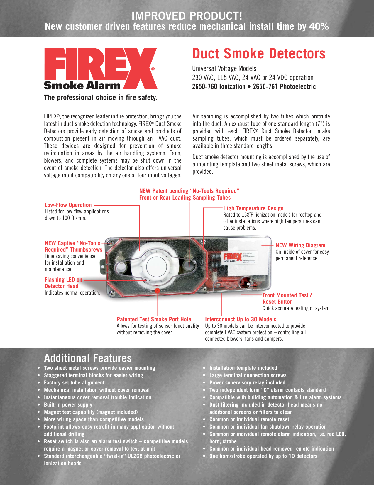
FIREX®, the recognized leader in fire protection, brings you the latest in duct smoke detection technology. FIREX® Duct Smoke Detectors provide early detection of smoke and products of combustion present in air moving through an HVAC duct. These devices are designed for prevention of smoke recirculation in areas by the air handling systems. Fans, blowers, and complete systems may be shut down in the event of smoke detection. The detector also offers universal voltage input compatibility on any one of four input voltages.
Air sampling is accomplished by two tubes which protrude into the duct. An exhaust tube of one standard length (7”) is provided with each FIREX® Duct Smoke Detector. Intake sampling tubes, which must be ordered separately, are available in three standard lengths.
Duct smoke detector mounting is accomplished by the use of a mounting template and two sheet metal screws, which are provided.
###### NEW Patent pending “No-Tools Required” Front or Rear Loading Sampling Tubes
Low-Flow Operation Listed for low-flow applications down to 100 ft./min.
High Temperature Design Rated to 158˚F (ionization model) for rooftop and other installations where high temperatures can cause problems.

NEW Captive “No-Tools Required” Thumbscrews Time saving convenience for installation and maintenance.
NEW Wiring Diagram On inside of cover for easy, permanent reference.
Flashing LED on Detector Head Indicates normal operation.
Front Mounted Test / Reset Button Quick accurate testing of system.
###### Interconnect Up to 30 Models
Patented Test Smoke Port Hole Allows for testing of sensor functionality without removing the cover.
Up to 30 models can be interconnected to provide complete HVAC system protection – controlling all connected blowers, fans and dampers.

Additional Features
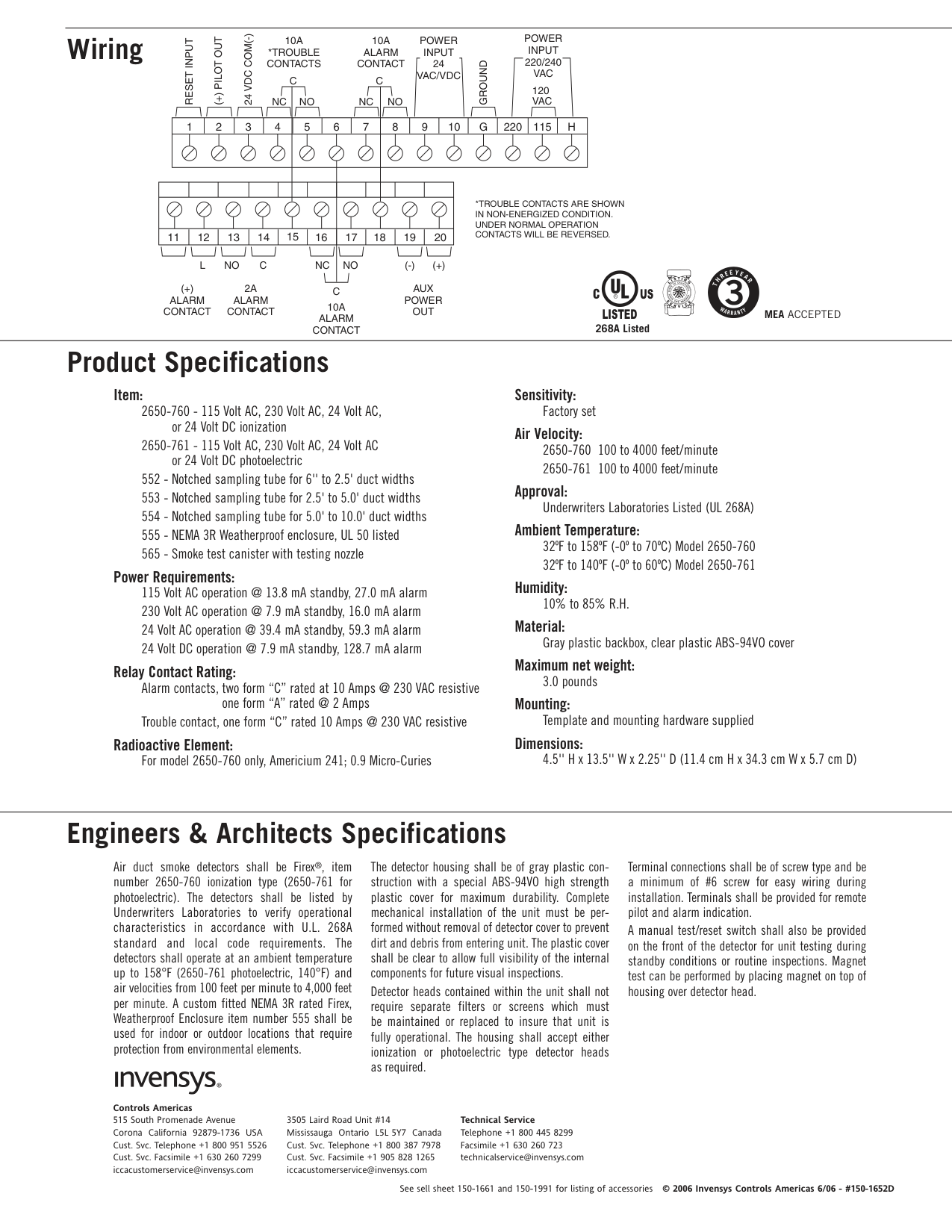
Wiring
POWER INPUT 220/240 VAC
24 VDC COM(-)
10A *TROUBLE CONTACTS
POWER INPUT 24 VAC/VDC
10A ALARM CONTACT
(+) PILOT OUT
RESET INPUT
GROUND
CC
120 VAC
NC
NO NC NO
1
2
3
4
5 6 7 8 9 10 G
220 115 H
*TROUBLE CONTACTS ARE SHOWN IN NON-ENERGIZED CONDITION. UNDER NORMAL OPERATION CONTACTS WILL BE REVERSED.
11 12 13 14 15 16 17 18 19 20
NO (-) (+)
LNO NCC
(+) ALARM CONTACT
2A ALARM
AUX POWER OUT
C
####### R US LISTED
CONTACT 10A
ALARM CONTACT
268A Listed
T
I
S
N
I
G
L
A
L
F
I
F O R N
O
E
T
A
A
L
A
A T E
H
S E
A
F
E
I
M
R
E
C
R
I
V
E
Y
E
E
R
A R
H
T
W
Y
MEA ACCEPTED
A
T
N
R
A
R
Product Specifications
##### Item:
Power Requirements: 115 Volt AC operation @ 13.8 mA standby, 27.0 mA alarm 230 Volt AC operation @ 7.9 mA standby, 16.0 mA alarm 24 Volt AC operation @ 39.4 mA standby, 59.3 mA alarm 24 Volt DC operation @ 7.9 mA standby, 128.7 mA alarm
##### Relay Contact Rating:
Alarm contacts, two form “C” rated at 10 Amps @ 230 VAC resistive one form “A” rated @ 2 Amps
Trouble contact, one form “C” rated 10 Amps @ 230 VAC resistive Radioactive Element:
For model 2650-760 only, Americium 241; 0.9 Micro-Curies
Sensitivity:
Factory set Air Velocity:
##### Approval:
Underwriters Laboratories Listed (UL 268A) Ambient Temperature:
32ºF to 158ºF (-0º to 70ºC) Model 2650-760 32ºF to 140ºF (-0º to 60ºC) Model 2650-761
##### Humidity:
10% to 85% R.H. Material:
Gray plastic backbox, clear plastic ABS-94VO cover Maximum net weight:
##### 3.0 pounds Mounting:
Template and mounting hardware supplied Dimensions:
4.5'' H x 13.5'' W x 2.25'' D (11.4 cm H x 34.3 cm W x 5.7 cm D)
Engineers & Architects Specifications
Air duct smoke detectors shall be Firex®‚ item number 2650-760 ionization type (2650-761 for photoelectric). The detectors shall be listed by Underwriters Laboratories to verify operational characteristics in accordance with U.L. 268A standard and local code requirements. The detectors shall operate at an ambient temperature up to 158°F (2650-761 photoelectric, 140°F) and air velocities from 100 feet per minute to 4,000 feet per minute. A custom fitted NEMA 3R rated Firex‚ Weatherproof Enclosure item number 555 shall be used for indoor or outdoor locations that require protection from environmental elements.
The detector housing shall be of gray plastic construction with a special ABS-94VO high strength plastic cover for maximum durability. Complete mechanical installation of the unit must be performed without removal of detector cover to prevent dirt and debris from entering unit. The plastic cover shall be clear to allow full visibility of the internal components for future visual inspections.
Detector heads contained within the unit shall not require separate filters or screens which must be maintained or replaced to insure that unit is fully operational. The housing shall accept either ionization or photoelectric type detector heads as required.
Controls Americas 515 South Promenade Avenue Corona California 92879-1736 USA Cust. Svc. Telephone +1 800 951 5526 Cust. Svc. Facsimile +1 630 260 7299 [email protected]
Technical Service Telephone +1 800 445 8299 Facsimile +1 630 260 723 [email protected]
3505 Laird Road Unit #14 Mississauga Ontario L5L 5Y7 Canada Cust. Svc. Telephone +1 800 387 7978 Cust. Svc. Facsimile +1 905 828 1265 [email protected]
Terminal connections shall be of screw type and be a minimum of #6 screw for easy wiring during installation. Terminals shall be provided for remote pilot and alarm indication.
A manual test/reset switch shall also be provided on the front of the detector for unit testing during standby conditions or routine inspections. Magnet test can be performed by placing magnet on top of housing over detector head.
See sell sheet 150-1661 and 150-1991 for listing of accessories © 2006 Invensys Controls Americas 6/06 - #150-1652D