
Fisher Paykel Myairvo 2 Humidified High Flow Generator System
Ask AI
— answers from the official manualAnswers from the official manual.
Common questions
Common Questions
10 totalHow do I turn on the AIRVO™ 2 humidifier?
Press and hold the On/Off button for at least 2 seconds. Ensure it is plugged into mains power with the power cord securely inserted.
What should I do if my AIRVO™ 2 doesn't turn on?
Press and hold the On/Off button for at least 2 seconds. Check that it is plugged into mains power with a secure, undamaged power cord. Use another power cord or outlet to confirm proper functioning.
What does 'Power out (black screen)' mean on the AIRVO™ 2?
This error usually indicates a dislodged or disconnected power cord. Check and reattach the power connection.
How do I fix the 'Check tube' or E38 error on my AIRVO™ 2?
Ensure the heated breathing tube is correctly attached, free of visible damage, and try reattaching it if in doubt. If necessary, use a new heated breathing tube.
How do I address the 'Check for blockages' or E121 error on my AIRVO™ 2?
Inspect and reposition the silicone flaps in the non-return valve if displaced. Ensure water chamber is not overfilled, replace chambers as needed.
How do I set up disinfection in my AIRVO™ 2 settings?
From the 'Warm-up' or 'Ready for use' screen, navigate through settings via Up and Down buttons with confirmation required before progressing to warmup.
Full Manual
33 pages
AIRVO™2
Technical Manual

############### This page has intentionally been left blank.
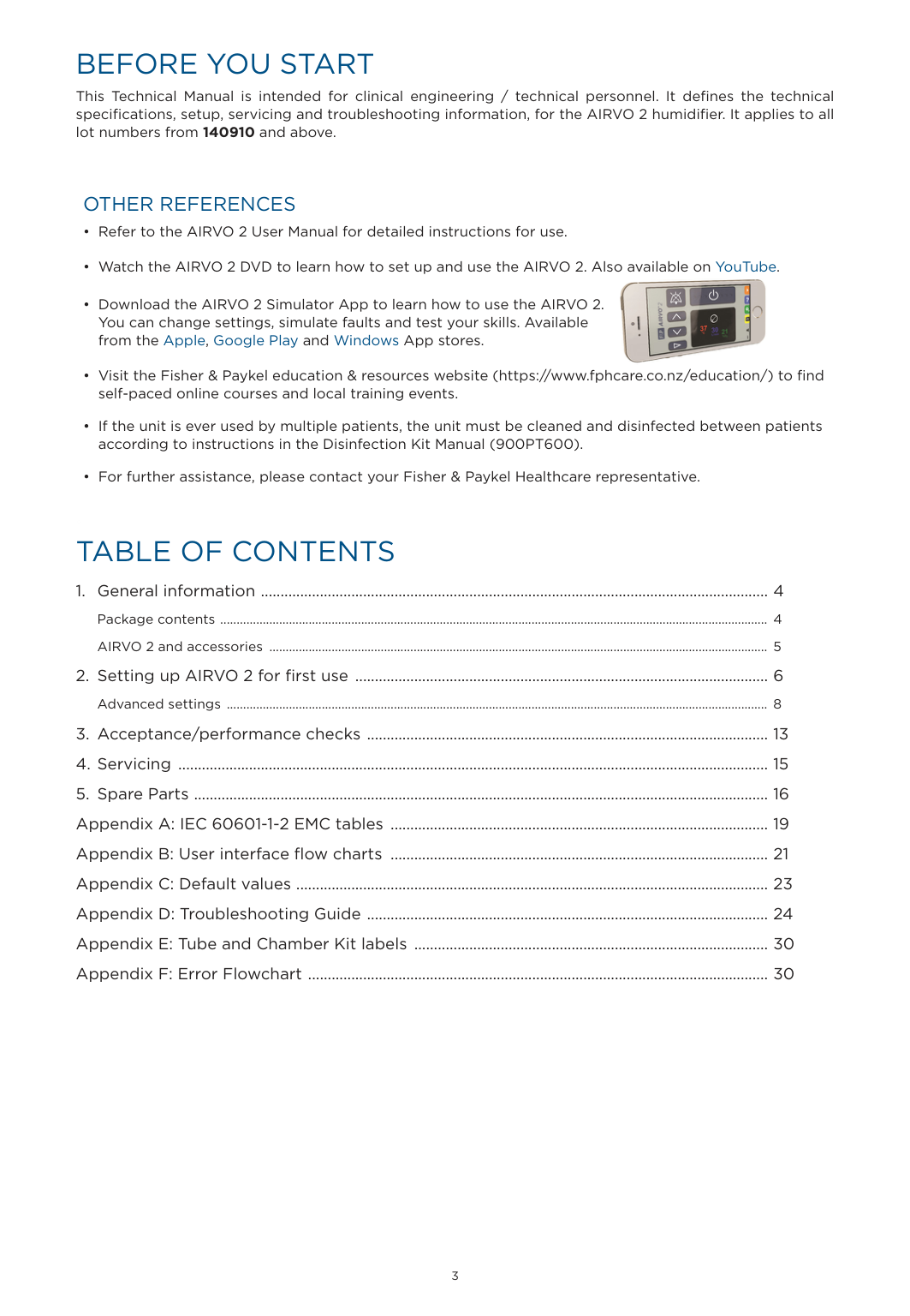
BEFORE YOU START
This Technical Manual is intended for clinical engineering / technical personnel. It defines the technical specifications, setup, servicing and troubleshooting information, for the AIRVO 2 humidifier. It applies to all lot numbers from 140910 and above.
######### OTHER REFERENCES

TABLE OF CONTENTS
1. GENERAL INFORMATION
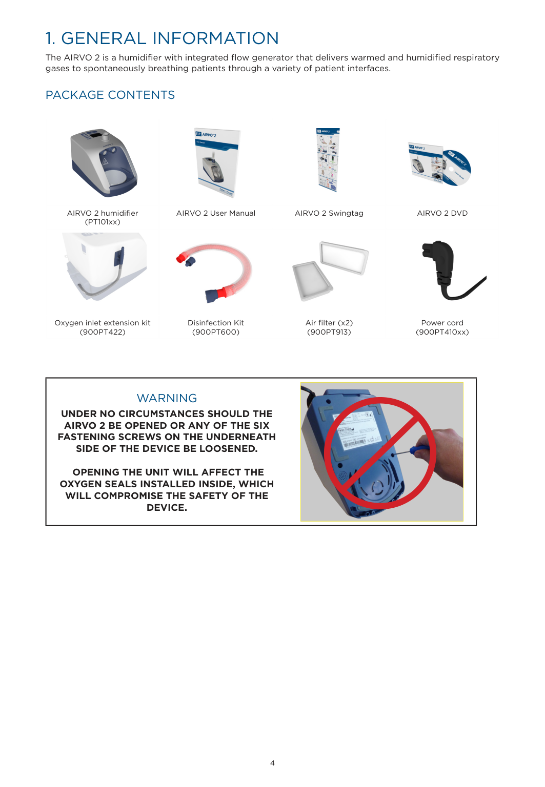
The AIRVO 2 is a humidifier with integrated flow generator that delivers warmed and humidified respiratory gases to spontaneously breathing patients through a variety of patient interfaces.
######### PACKAGE CONTENTS
||||| |---|---|---|---| |AIRVO 2 humidifier (PT101xx)|AIRVO 2 User Manual|AIRVO 2 Swingtag|AIRVO 2 DVD| ||||| |Oxygen inlet extension kit (900PT422)|Disinfection Kit (900PT600)|Air filter (x2) (900PT913)|Power cord (900PT410xx)|
|WARNING UNDER NO CIRCUMSTANCES SHOULD THE AIRVO 2 BE OPENED OR ANY OF THE SIX FASTENING SCREWS ON THE UNDERNEATH SIDE OF THE DEVICE BE LOOSENED.
OPENING THE UNIT WILL AFFECT THE OXYGEN SEALS INSTALLED INSIDE, WHICH WILL COMPROMISE THE SAFETY OF THE DEVICE.
|| |---| | |---|
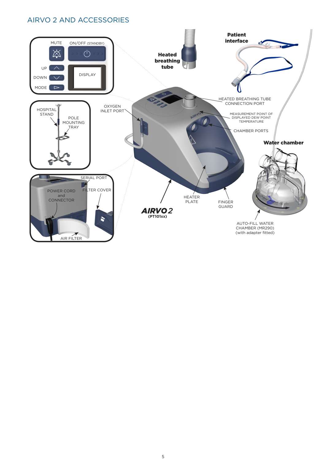
######### AIRVO 2 AND ACCESSORIES


Patient interfaceON/OFF(STANDBY)MUTE

Heated breathing tube
UP DOWN
DISPLAY
MODE
HEATED BREATHING TUBE CONNECTION PORT

OXYGEN INLET PORT
HOSPITAL STAND

MEASUREMENT POINT OF DISPLAYED DEW POINT TEMPERATURE
POLE MOUNTING TRAY
CHAMBER PORTS
Water chamber

SERIAL PORT
FILTER COVERPOWER CORD
and CONNECTOR
HEATER
PLATE FINGER GUARD
####### AIRVO2
(PT101xx)
AUTO-FILL WATER CHAMBER (MR290) (with adapter fitted)
AIR FILTER
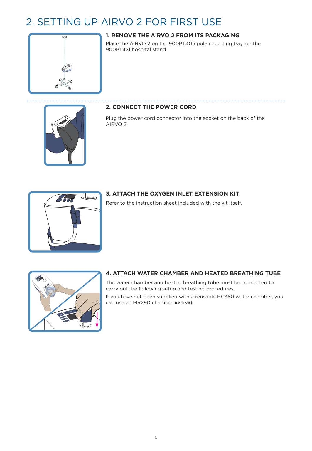
2. SETTING UP AIRVO 2 FOR FIRST USE
Place the AIRVO 2 on the 900PT405 pole mounting tray, on the 900PT421 hospital stand.
Plug the power cord connector into the socket on the back of the AIRVO 2.

The water chamber and heated breathing tube must be connected to carry out the following setup and testing procedures. If you have not been supplied with a reusable HC360 water chamber, you can use an MR290 chamber instead.
|| |---|


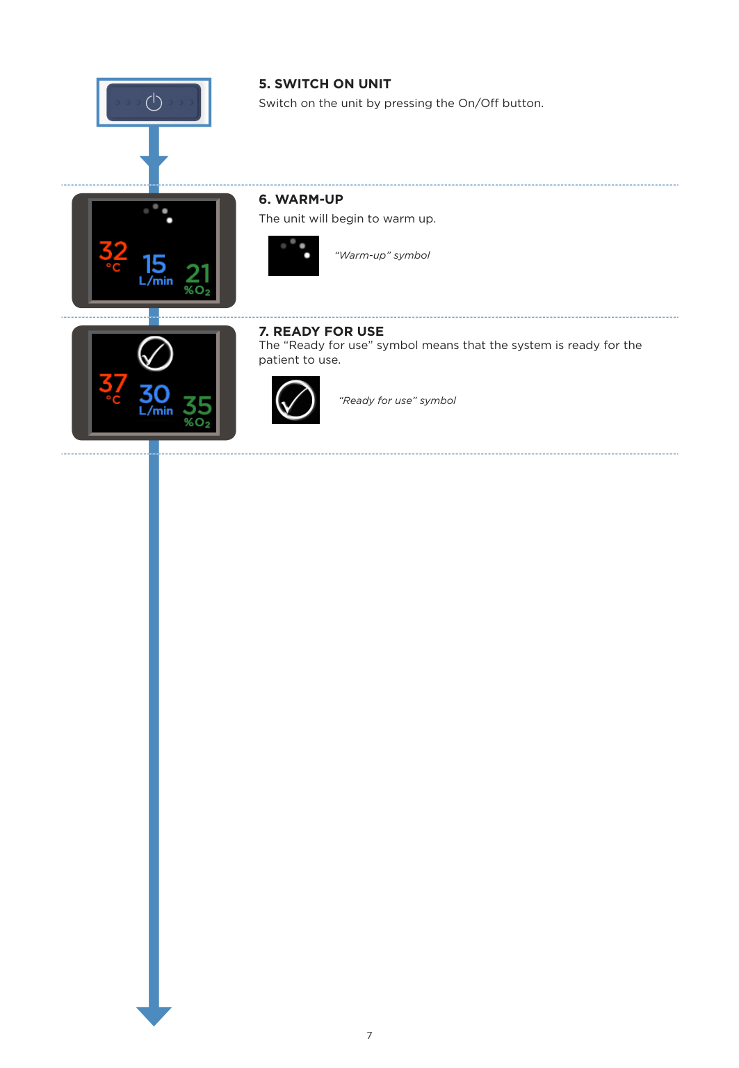
“Warm-up” symbol


“Ready for use” symbol

| | |---|

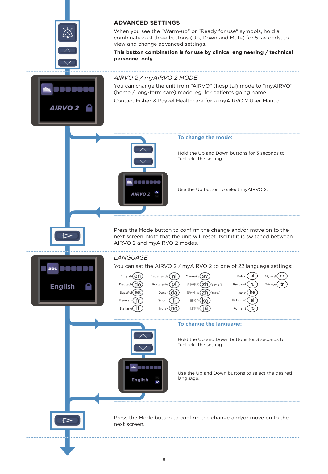
ADVANCED SETTINGS When you see the “Warm-up” or “Ready for use” symbols, hold a combination of three buttons (Up, Down and Mute) for 5 seconds, to view and change advanced settings.
This button combination is for use by clinical engineering / technical personnel only.
AIRVO 2 / myAIRVO 2 MODE You can change the unit from “AIRVO” (hospital) mode to “myAIRVO” (home / long-term care) mode, eg. for patients going home. Contact Fisher & Paykel Healthcare for a myAIRVO 2 User Manual.
| | | |---|---| | ||

############## To change the mode:
Hold the Up and Down buttons for 3 seconds to “unlock” the setting.
Use the Up button to select myAIRVO 2.

| | |---|

Press the Mode button to confirm the change and/or move on to the next screen. Note that the unit will reset itself if it is switched between AIRVO 2 and myAIRVO 2 modes.
LANGUAGE You can set the AIRVO 2 / myAIRVO 2 to one of 22 language settings:


English Nederlands Svenska Polski pl العربية ar Deutsch Português 简体中文 [simp.] Русский ru Türkçe tr Español Dansk 繁体中文 [trad.] עברית he Français Suomi Ελληνικά el


Italiano Norsk 日本語 Română ro
| | | |---|---| || |

############## To change the language:
Hold the Up and Down buttons for 3 seconds to “unlock” the setting.
Use the Up and Down buttons to select the desired language.

| | |---|
Press the Mode button to confirm the change and/or move on to the next screen.

############## 95
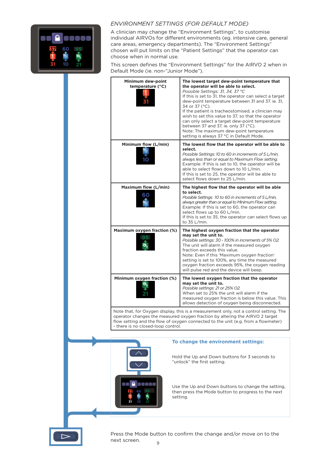
ENVIRONMENT SETTINGS (FOR DEFAULT MODE) A clinician may change the “Environment Settings”, to customise individual AIRVOs for different environments (eg. intensive care, general care areas, emergency departments). The “Environment Settings” chosen will put limits on the “Patient Settings” that the operator can choose when in normal use. This screen defines the “Environment Settings” for the AIRVO 2 when in Default Mode (ie. non-“Junior Mode”).
|Minimum dew-point temperature (°C)
|The lowest target dew-point temperature that the operator will be able to select. Possible Settings: 31, 34, 37 °C If this is set to 31, the operator can select a target dew-point temperature between 31 and 37. ie. 31, 34 or 37 (°C). If the patient is tracheostomised, a clinician may wish to set this value to 37, so that the operator can only select a target dew-point temperature between 37 and 37, ie. only 37 (°C). Note: The maximum dew-point temperature setting is always 37 °C in Default Mode.| |---|---| |Minimum flow (L/min)
|The lowest flow that the operator will be able to select. Possible Settings: 10 to 60 in increments of 5 L/min, always less than or equal to Maximum Flow setting. Example: If this is set to 10, the operator will be able to select flows down to 10 L/min. If this is set to 25, the operator will be able to select flows down to 25 L/min.| |Maximum flow (L/min)
|The highest flow that the operator will be able to select. Possible Settings: 10 to 60 in increments of 5 L/min, always greater than or equal to Minimum Flow setting. Example: If this is set to 60, the operator can select flows up to 60 L/min. If this is set to 35, the operator can select flows up to 35 L/min.| |Maximum oxygen fraction (%) 95

|The highest oxygen fraction that the operator may set the unit to. Possible settings: 30 - 100% in increments of 5% O2. The unit will alarm if the measured oxygen fraction exceeds this value. Note: Even if this ‘Maximum oxygen fraction‘ setting is set to 100%, any time the measured oxygen fraction exceeds 95%, the oxygen reading will pulse red and the device will beep.| |Minimum oxygen fraction (%)
|The lowest oxygen fraction that the operator may set the unit to. Possible settings: 21 or 25% O2. When set to 25% the unit will alarm if the measured oxygen fraction is below this value. This allows detection of oxygen being disconnected.| |Note that, for Oxygen display, this is a measurement only, not a control setting. The operator changes the measured oxygen fraction by altering the AIRVO 2 target flow setting and the flow of oxygen connected to the unit (e.g. from a flowmeter)
- there is no closed-loop control.|Note that, for Oxygen display, this is a measurement only, not a control setting. The operator changes the measured oxygen fraction by altering the AIRVO 2 target flow setting and the flow of oxygen connected to the unit (e.g. from a flowmeter)
- there is no closed-loop control.|
| | | |---|---| | |
95|

############## To change the environment settings:
Hold the Up and Down buttons for 3 seconds to “unlock” the first setting.
Use the Up and Down buttons to change the setting, then press the Mode button to progress to the next setting.

| | |---|
Press the Mode button to confirm the change and/or move on to the next screen.

############# 95
100
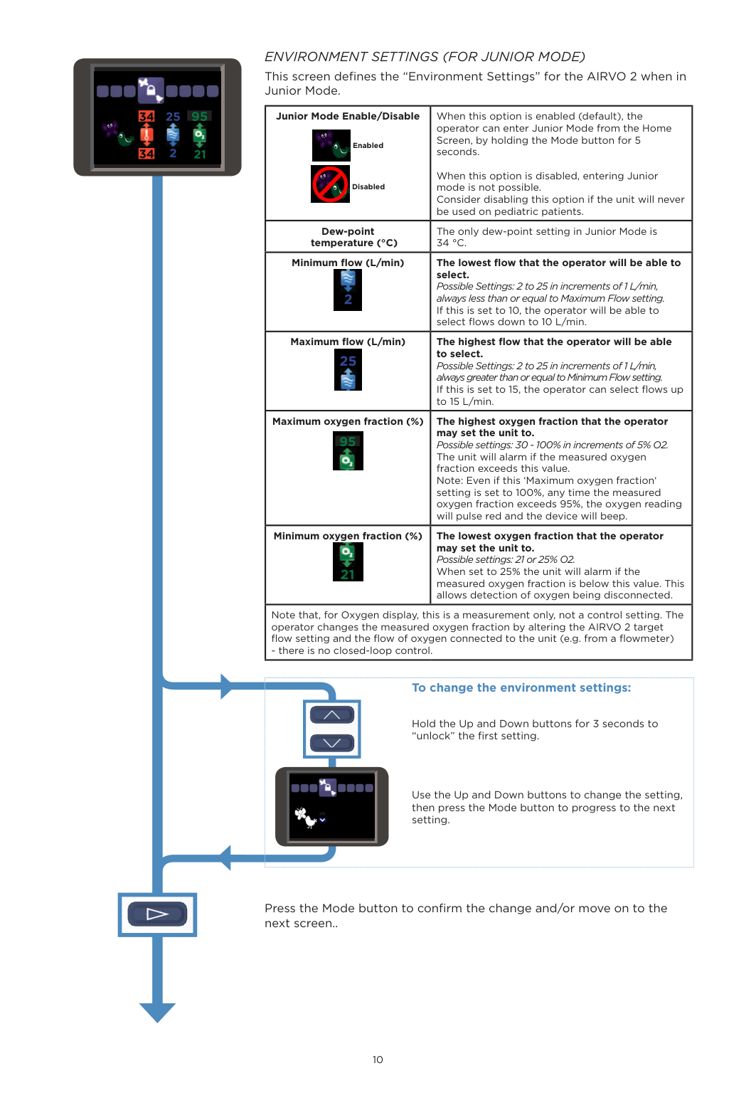
ENVIRONMENT SETTINGS (FOR JUNIOR MODE) This screen defines the “Environment Settings” for the AIRVO 2 when in Junior Mode.
|Junior Mode Enable/Disable

Enabled

Disabled|When this option is enabled (default), the operator can enter Junior Mode from the Home Screen, by holding the Mode button for 5 seconds.
When this option is disabled, entering Junior mode is not possible. Consider disabling this option if the unit will never be used on pediatric patients.| |---|---| |Dew-point temperature (°C)|The only dew-point setting in Junior Mode is 34 °C.| |Minimum flow (L/min)
|The lowest flow that the operator will be able to select. Possible Settings: 2 to 25 in increments of 1 L/min, always less than or equal to Maximum Flow setting. If this is set to 10, the operator will be able to select flows down to 10 L/min.| |Maximum flow (L/min)
|The highest flow that the operator will be able to select. Possible Settings: 2 to 25 in increments of 1 L/min, always greater than or equal to Minimum Flow setting. If this is set to 15, the operator can select flows up to 15 L/min.| |Maximum oxygen fraction (%) 95

|The highest oxygen fraction that the operator may set the unit to. Possible settings: 30 - 100% in increments of 5% O2. The unit will alarm if the measured oxygen fraction exceeds this value. Note: Even if this ‘Maximum oxygen fraction‘ setting is set to 100%, any time the measured oxygen fraction exceeds 95%, the oxygen reading will pulse red and the device will beep.| |Minimum oxygen fraction (%)
|The lowest oxygen fraction that the operator may set the unit to. Possible settings: 21 or 25% O2. When set to 25% the unit will alarm if the measured oxygen fraction is below this value. This allows detection of oxygen being disconnected.|
|Note that, for Oxygen display, this is a measurement only, not a control setting. The operator changes the measured oxygen fraction by altering the AIRVO 2 target flow setting and the flow of oxygen connected to the unit (e.g. from a flowmeter)
- there is no closed-loop control.|Note that, for Oxygen display, this is a measurement only, not a control setting. The operator changes the measured oxygen fraction by altering the AIRVO 2 target flow setting and the flow of oxygen connected to the unit (e.g. from a flowmeter)
- there is no closed-loop control.|
| | | |---|---| || |

############## To change the environment settings:
Hold the Up and Down buttons for 3 seconds to “unlock” the first setting.
Use the Up and Down buttons to change the setting, then press the Mode button to progress to the next setting.

| | |---|
Press the Mode button to confirm the change and/or move on to the next screen..

########## 25
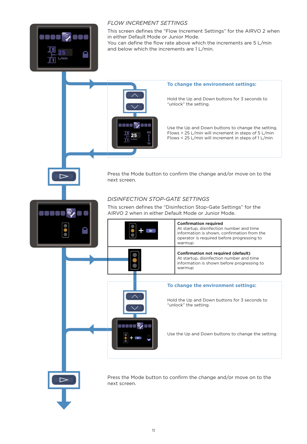
FLOW INCREMENT SETTINGS This screen defines the “Flow Increment Settings” for the AIRVO 2 when in either Default Mode or Junior Mode. You can define the flow rate above which the increments are 5 L/min and below which the increments are 1 L/min.
| | | |---|---| |2|
|

############## To change the environment settings:
Hold the Up and Down buttons for 3 seconds to “unlock” the setting.
Use the Up and Down buttons to change the setting. Flows > 25 L/min will increment in steps of 5 L/min Flows < 25 L/min will increment in steps of 1 L/min

| | |---|


Press the Mode button to confirm the change and/or move on to the next screen.
DISINFECTION STOP-GATE SETTINGS This screen defines the “Disinfection Stop-Gate Settings” for the AIRVO 2 when in either Default Mode or Junior Mode.


Confirmation required At startup, disinfection number and time information is shown, confirmation from the operator is required before progressing to warmup
Confirmation not required (default) At startup, disinfection number and time information is shown before progressing to warmup


############## To change the environment settings:
Hold the Up and Down buttons for 3 seconds to “unlock” the setting.
Use the Up and Down buttons to change the setting.

| | |---|
Press the Mode button to confirm the change and/or move on to the next screen.


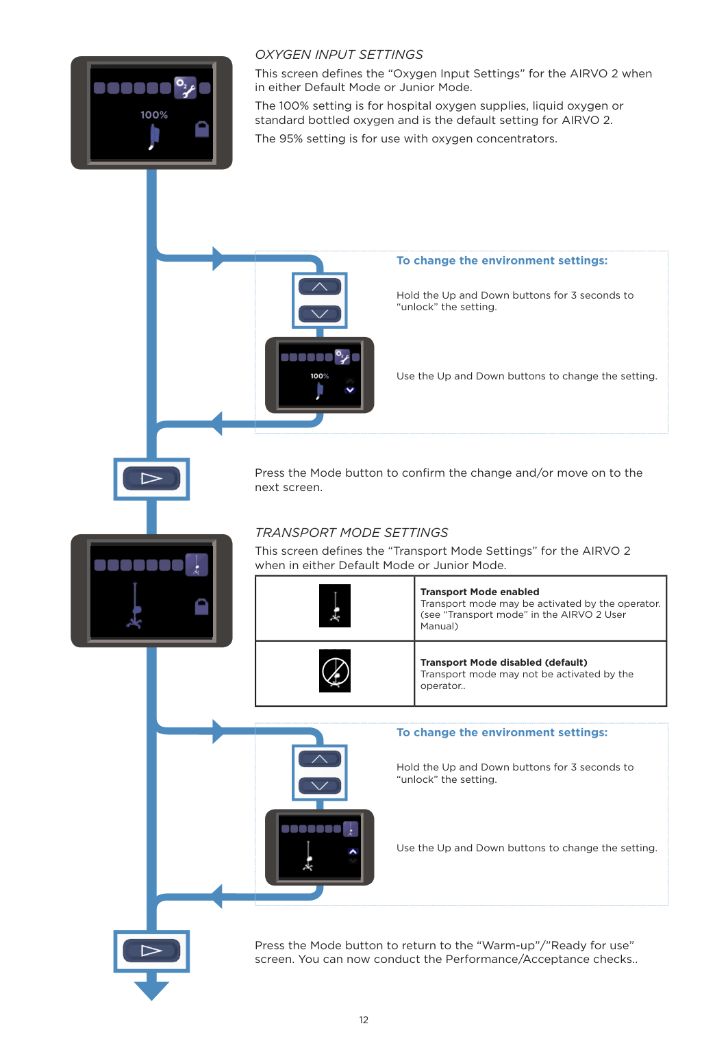
OXYGEN INPUT SETTINGS This screen defines the “Oxygen Input Settings” for the AIRVO 2 when in either Default Mode or Junior Mode. The 100% setting is for hospital oxygen supplies, liquid oxygen or standard bottled oxygen and is the default setting for AIRVO 2. The 95% setting is for use with oxygen concentrators.
| | | |---|---| | |
|

############## To change the environment settings:
Hold the Up and Down buttons for 3 seconds to “unlock” the setting.
Use the Up and Down buttons to change the setting.

| | |---|

Press the Mode button to confirm the change and/or move on to the next screen.
TRANSPORT MODE SETTINGS This screen defines the “Transport Mode Settings” for the AIRVO 2 when in either Default Mode or Junior Mode.
||Transport Mode enabled Transport mode may be activated by the operator. (see “Transport mode” in the AIRVO 2 User Manual)| |---|---| ||Transport Mode disabled (default) Transport mode may not be activated by the operator..|
| | | |---|---| || |

############## To change the environment settings:
Hold the Up and Down buttons for 3 seconds to “unlock” the setting.
Use the Up and Down buttons to change the setting.

| | |---|
Press the Mode button to return to the “Warm-up”/”Ready for use” screen. You can now conduct the Performance/Acceptance checks..
3. ACCEPTANCE/PERFORMANCE CHECKS
This section contains performance checks which can be carried out on the AIRVO 2, however there is no manufacturer requirement to carry out these checks on a routine basis. These checks test the basic functions of the unit, the operation of the flow sensor and the audible alarm signal.
########### SENSOR CHECKS
|To ensure quality and patient safety, Fisher & Paykel Healthcare undertakes stringent testing to each and every unit manufactured. The AIRVO 2’s sensors, measuring temperature, flow and oxygen, have been carefully designed to exacting criteria, and are calibrated and tested in our controlled work environment to strict limits. Furthermore, the AIRVO 2 itself carries out regular self-checks during normal use, comparing sensor readings against expected values.
Do not perform additional tests of internal sensor accuracy, as these often produce erroneous results due to limitations of the external test environment and equipment used, particularly given the temperature, humidity content and/or flow of the gases being delivered by the AIRVO 2.| |---|
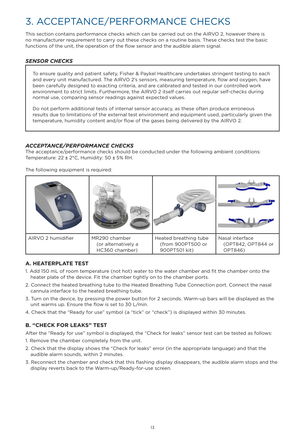
ACCEPTANCE/PERFORMANCE CHECKS The acceptance/performance checks should be conducted under the following ambient conditions: Temperature: 22 ± 2°C, Humidity: 50 ± 5% RH.
The following equipment is required:
||
| |
| |---|---|---|---| |AIRVO 2 humidifier|MR290 chamber
(or alternatively a HC360 chamber)|Heated breathing tube (from 900PT500 or 900PT501 kit)|Nasal interface (OPT842, OPT844 or OPT846)|
########### A. HEATERPLATE TEST
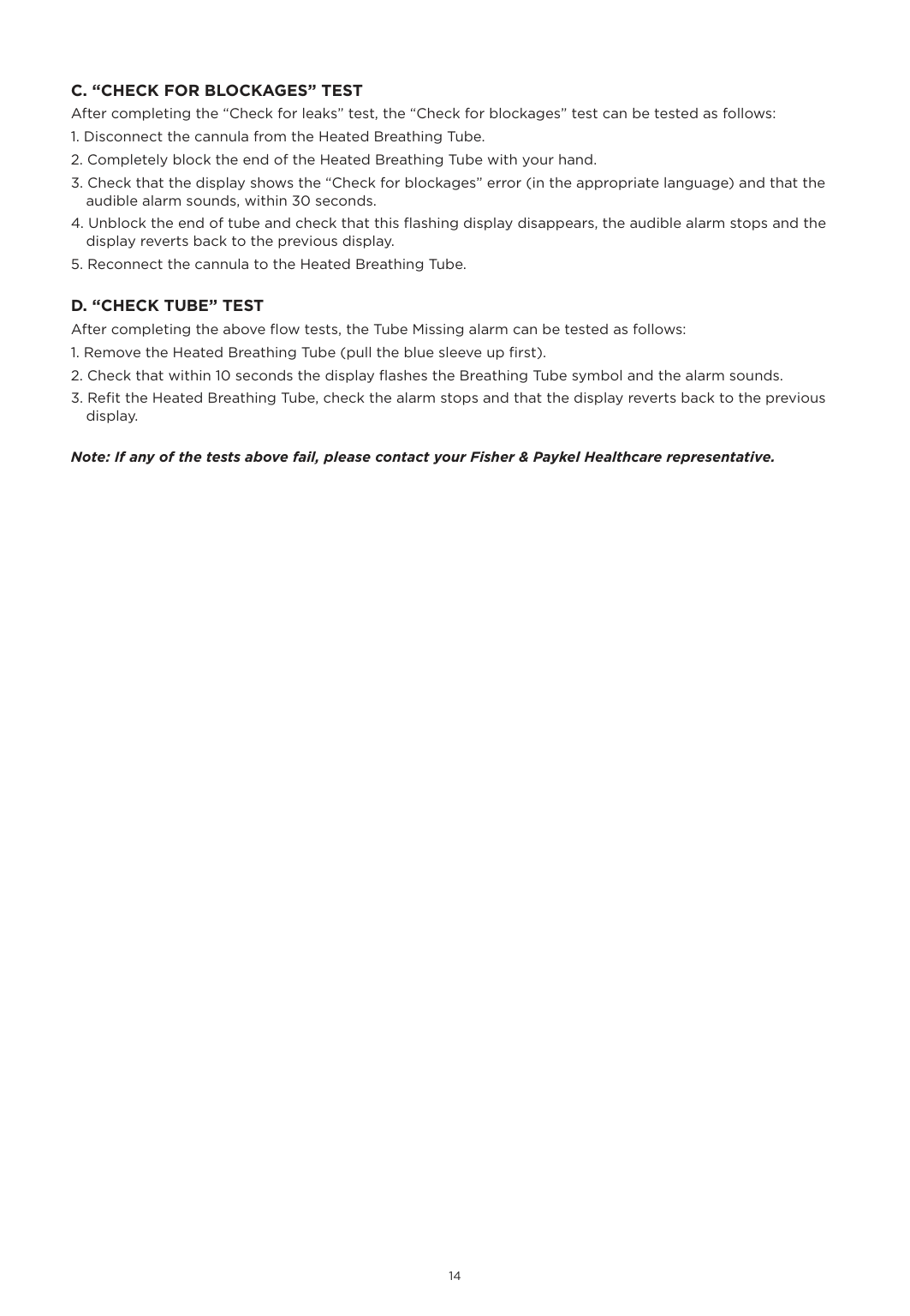
############ B. “CHECK FOR LEAKS” TESTAfter the “Ready for use” symbol is displayed, the “Check for leaks” sensor test can be tested as follows:
############## Note: If any of the tests above fail, please contact your Fisher & Paykel Healthcare representative.
4. SERVICING
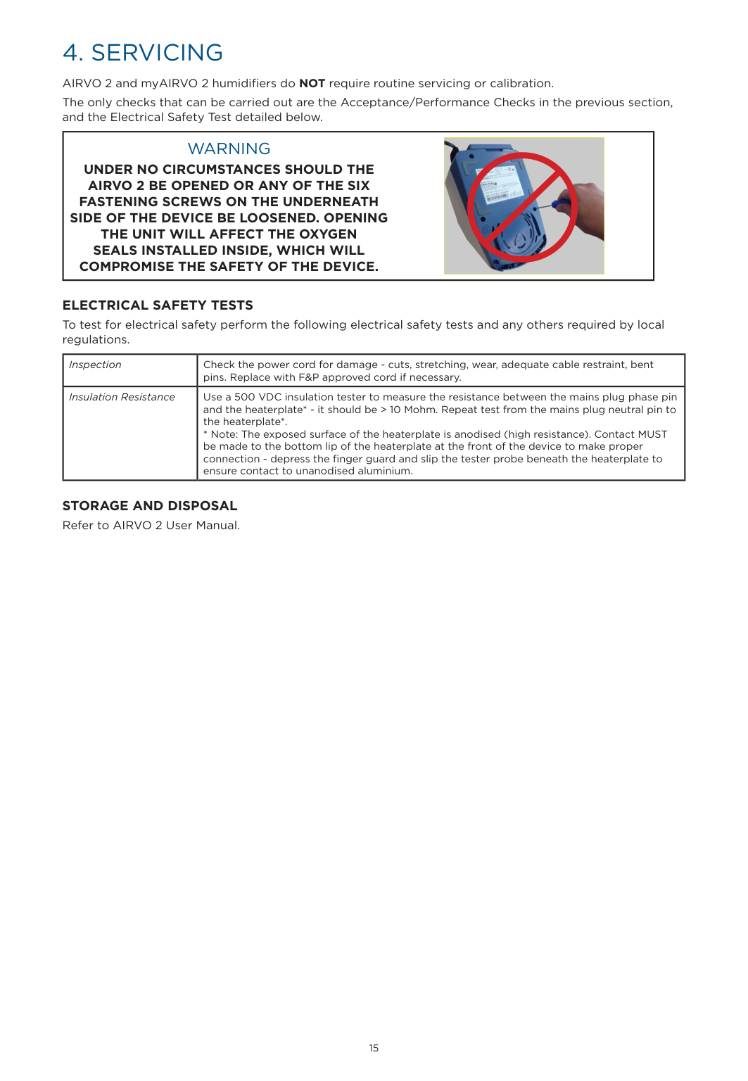
AIRVO 2 and myAIRVO 2 humidifiers do NOT require routine servicing or calibration. The only checks that can be carried out are the Acceptance/Performance Checks in the previous section, and the Electrical Safety Test detailed below.
|WARNING UNDER NO CIRCUMSTANCES SHOULD THE AIRVO 2 BE OPENED OR ANY OF THE SIX FASTENING SCREWS ON THE UNDERNEATH SIDE OF THE DEVICE BE LOOSENED. OPENING THE UNIT WILL AFFECT THE OXYGEN SEALS INSTALLED INSIDE, WHICH WILL COMPROMISE THE SAFETY OF THE DEVICE.
|| |---| | |---|
ELECTRICAL SAFETY TESTS To test for electrical safety perform the following electrical safety tests and any others required by local regulations.
|Inspection|Check the power cord for damage - cuts, stretching, wear, adequate cable restraint, bent pins. Replace with F&P approved cord if necessary.| |---|---| |Insulation Resistance|Use a 500 VDC insulation tester to measure the resistance between the mains plug phase pin and the heaterplate* - it should be > 10 Mohm. Repeat test from the mains plug neutral pin to the heaterplate*.
* Note: The exposed surface of the heaterplate is anodised (high resistance). Contact MUST be made to the bottom lip of the heaterplate at the front of the device to make proper connection - depress the finger guard and slip the tester probe beneath the heaterplate to ensure contact to unanodised aluminium.|
STORAGE AND DISPOSAL Refer to AIRVO 2 User Manual.
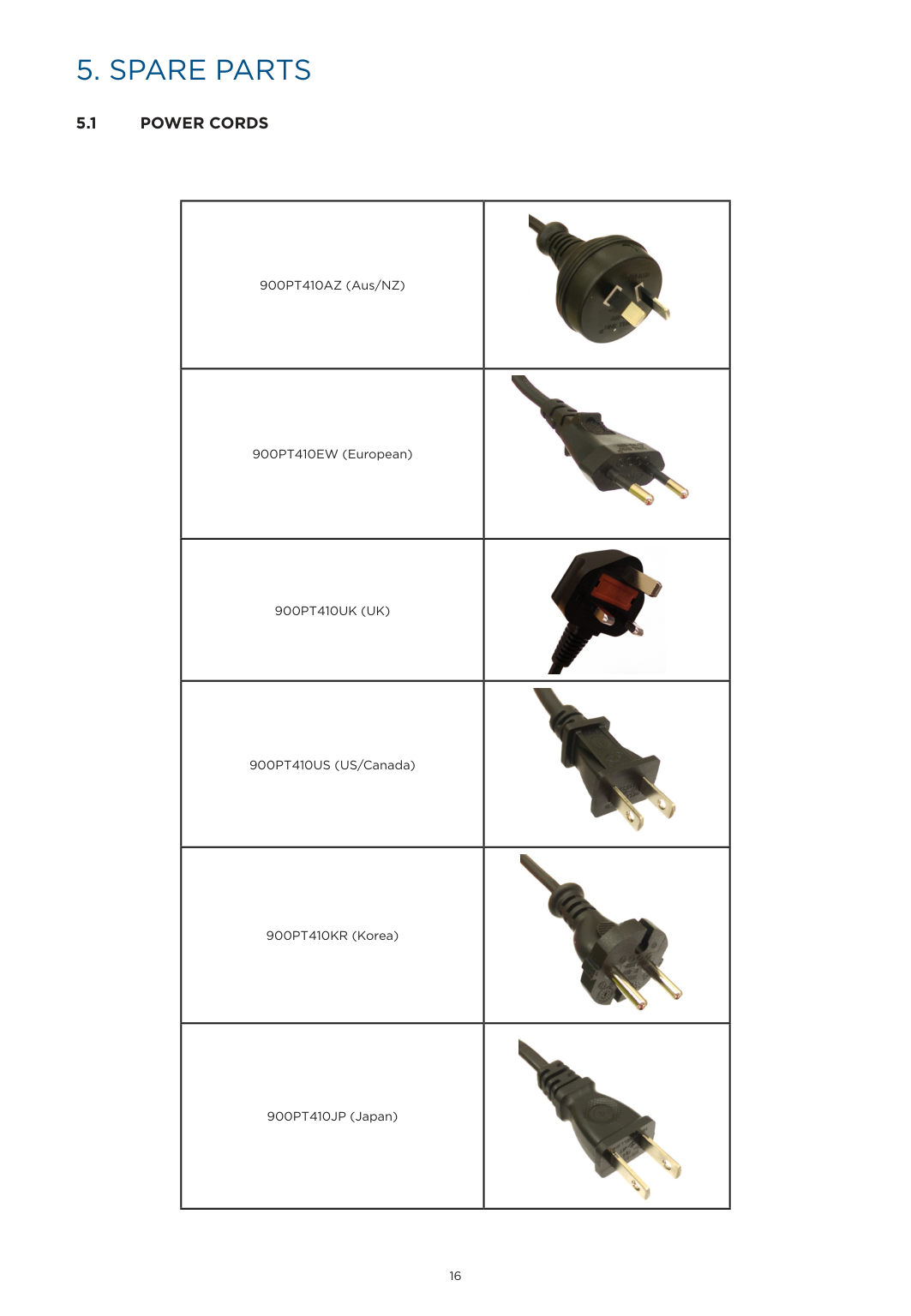
5. SPARE PARTS
|900PT410AZ (Aus/NZ)|| |---|---| |900PT410EW (European)|| |900PT410UK (UK)|| |900PT410US (US/Canada)|| |900PT410KR (Korea)|| |900PT410JP (Japan)||
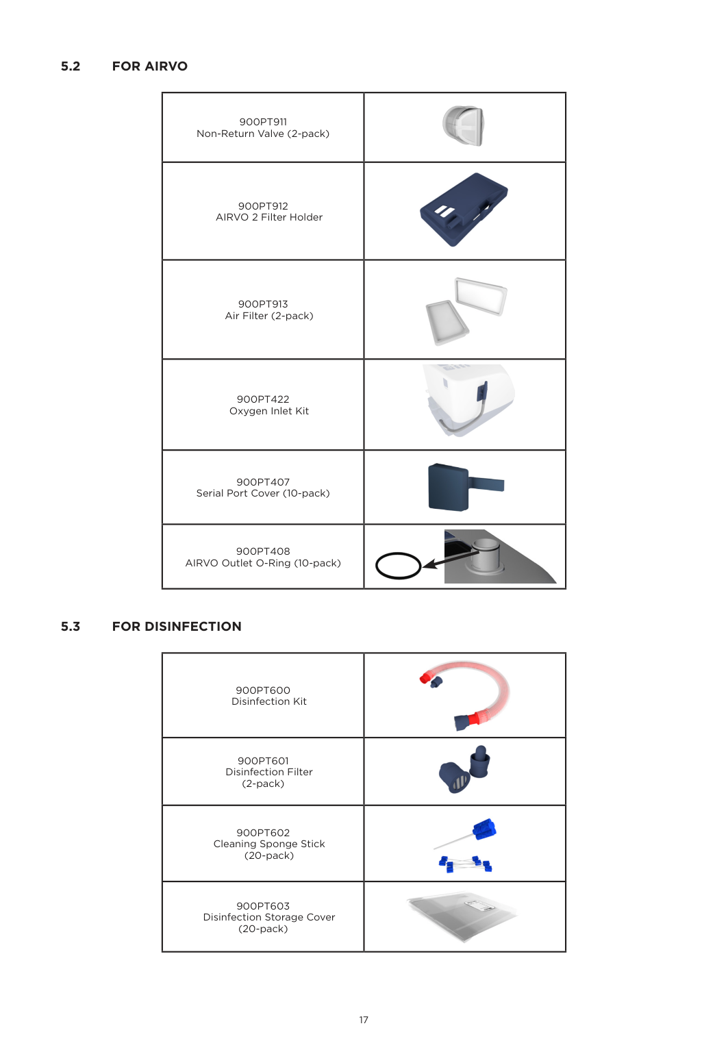
########### 5.2 FOR AIRVO
|900PT911 Non-Return Valve (2-pack)|| |---|---| |900PT912 AIRVO 2 Filter Holder|| |900PT913 Air Filter (2-pack)|| |900PT422 Oxygen Inlet Kit|| |900PT407 Serial Port Cover (10-pack)|| |900PT408 AIRVO Outlet O-Ring (10-pack)|

|
########### 5.3 FOR DISINFECTION
|900PT600 Disinfection Kit|| |---|---| |900PT601 Disinfection Filter (2-pack)|| |900PT602
Cleaning Sponge Stick (20-pack)|| |900PT603 Disinfection Storage Cover (20-pack)||
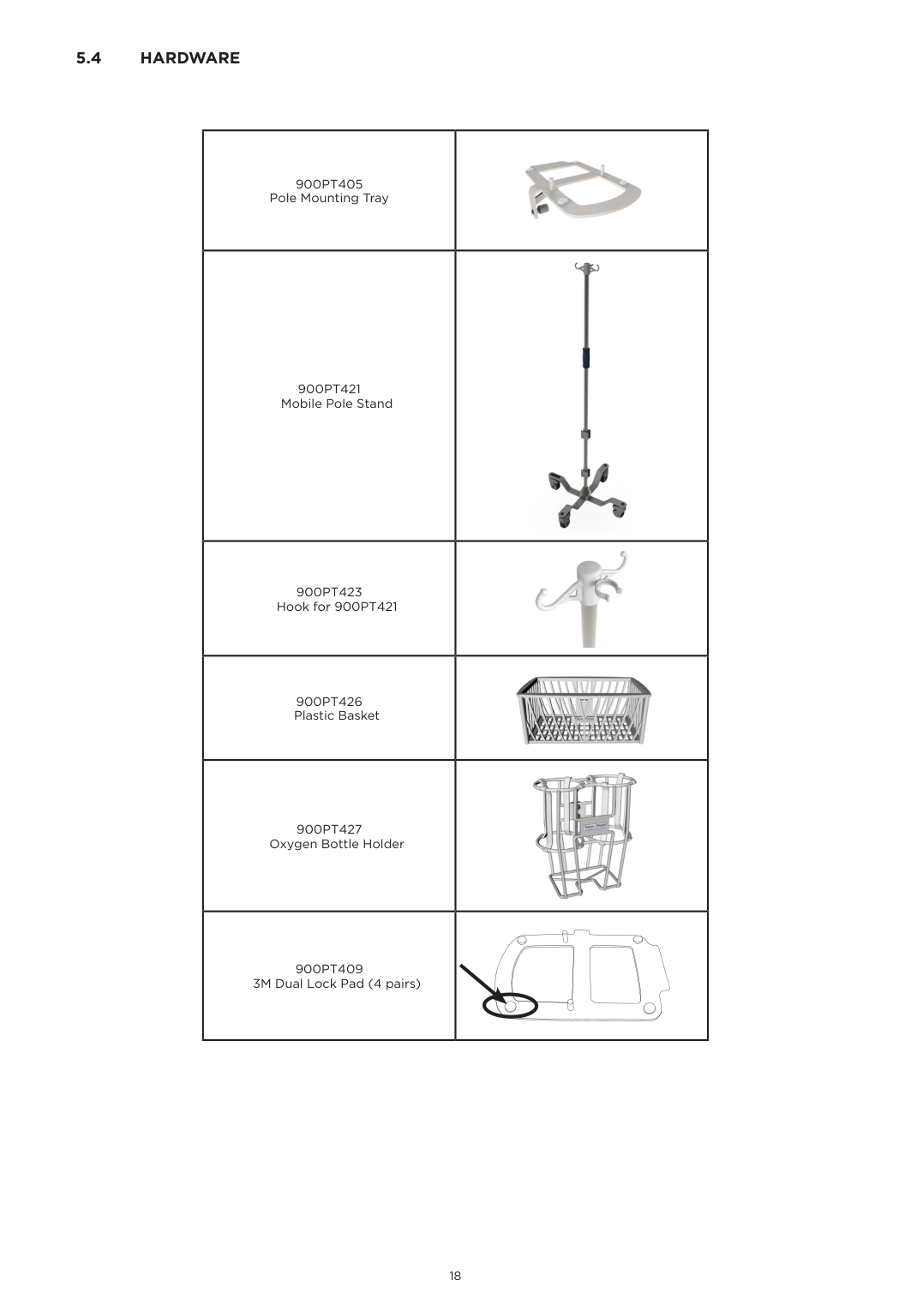
########### 5.4 HARDWARE
|900PT405 Pole Mounting Tray|| |---|---| |900PT421 Mobile Pole Stand|| |900PT423 Hook for 900PT421|| |900PT426 Plastic Basket|
| |900PT427 Oxygen Bottle Holder|| |900PT409 3M Dual Lock Pad (4 pairs)| |
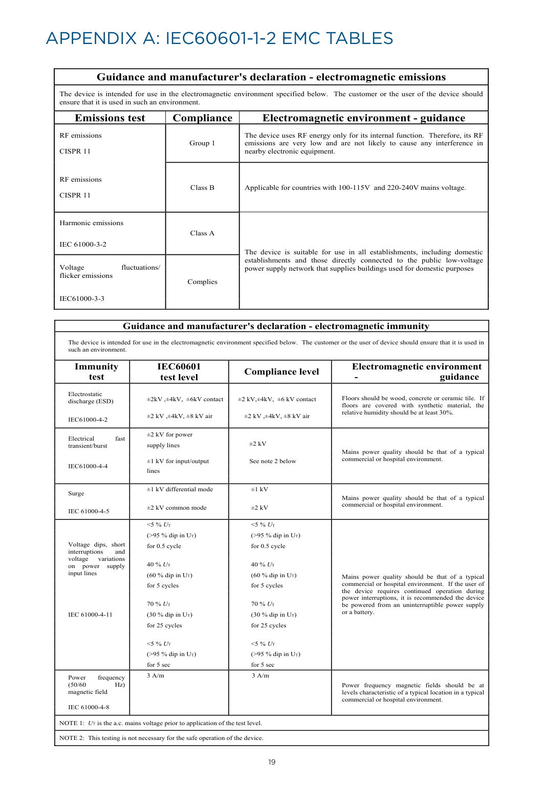
APPENDIX A: IEC60601-1-2 EMC TABLES
|Guidance and manufacturer's declaration - electromagnetic emissions|Guidance and manufacturer's declaration - electromagnetic emissions|Guidance and manufacturer's declaration - electromagnetic emissions| |---|---|---| |The device is intended for use in the electromagnetic environment specified below. The customer or the user of the device should ensure that it is used in such an environment.|The device is intended for use in the electromagnetic environment specified below. The customer or the user of the device should ensure that it is used in such an environment.|The device is intended for use in the electromagnetic environment specified below. The customer or the user of the device should ensure that it is used in such an environment.| |Emissions test|Compliance|Electromagnetic environment - guidance| |RF emissions CISPR 11
RF emissions CISPR 11
|Group 1|The device uses RF energy only for its internal function. Therefore, its RF emissions are very low and are not likely to cause any interference in nearby electronic equipment.| |RF emissions CISPR 11
RF emissions CISPR 11
|Class B|Applicable for countries with 100-115V and 220-240V mains voltage.| |Harmonic emissions
IEC 61000-3-2|Class A|The device is suitable for use in all establishments, including domestic establishments and those directly connected to the public low-voltage power supply network that supplies buildings used for domestic purposes
| |Voltage fluctuations/ flicker emissions
IEC61000-3-3|Complies|The device is suitable for use in all establishments, including domestic establishments and those directly connected to the public low-voltage power supply network that supplies buildings used for domestic purposes
|
|Guidance and manufacturer's declaration - electromagnetic immunity|Guidance and manufacturer's declaration - electromagnetic immunity|Guidance and manufacturer's declaration - electromagnetic immunity|Guidance and manufacturer's declaration - electromagnetic immunity| |---|---|---|---| |The device is intended for use in the electromagnetic environment specified below. The customer or the user of device should ensure that it is used in such an environment.|The device is intended for use in the electromagnetic environment specified below. The customer or the user of device should ensure that it is used in such an environment.|The device is intended for use in the electromagnetic environment specified below. The customer or the user of device should ensure that it is used in such an environment.|The device is intended for use in the electromagnetic environment specified below. The customer or the user of device should ensure that it is used in such an environment.| |Immunity test|IEC60601 test level|Compliance level
|Electromagnetic environment - guidance| |Electrostatic discharge (ESD)
IEC61000-4-2|±2kV ,±4kV, ±6kV contact
±2 kV ,±4kV, ±8 kV air|±2 kV,±4kV, ±6 kV contact
±2 kV ,±4kV, ±8 kV air
|Floors should be wood, concrete or ceramic tile. If floors are covered with synthetic material, the relative humidity should be at least 30%.| |Electrical fast transient/burst
IEC61000-4-4|±2 kV for power supply lines
±1 kV for input/output lines
|±2 kV
See note 2 below|Mains power quality should be that of a typical commercial or hospital environment.| |Surge
IEC 61000-4-5|±1 kV differential mode
±2 kV common mode
|±1 kV
±2 kV
|Mains power quality should be that of a typical commercial or hospital environment.
| |Voltage dips, short interruptions and voltage variations on power supply input lines
IEC 61000-4-11|A
<5 % UT (>95 % dip in UT) for 0.5 cycle
40 % UT (60 % dip in UT) for 5 cycles
70 % UT (30 % dip in UT) for 25 cycles
<5 % UT (>95 % dip in UT) for 5 sec|irvoTM Series Humidifier
<5 % UT (>95 % dip in UT) for 0.5 cycle
40 % UT (60 % dip in UT) for 5 cycles
70 % UT (30 % dip in UT) for 25 cycles
<5 % UT (>95 % dip in UT) for 5 sec|Mains power quality should be that of a typical commercial or hospital environment. If the user of the device requires continued operation during power interruptions, it is recommended the device be powered from an uninterruptible power supply or a battery.
| |Power frequency (50/60 Hz) magnetic field
IEC 61000-4-8|Technical M3 A/m|Models PT101 and PT100 nual Rev D (Part Numbe3 A/m|185044926)Power frequency magnetic fields should be at levels characteristic of a typical location in a typical commercial or hospital environment.
| |NOTE 1: UT is the a.c. mains voltage prior to application of the test level.|NOTE 1: UT is the a.c. mains voltage prior to application of the test level.|NOTE 1: UT is the a.c. mains voltage prior to application of the test level.|NOTE 1: UT is the a.c. mains voltage prior to application of the test level.| |NOTE 2: This testing is not necessary for the safe operation of the device.|NOTE 2: This testing is not necessary for the safe operation of the device.|NOTE 2: This testing is not necessary for the safe operation of the device.|NOTE 2: This testing is not necessary for the safe operation of the device.|
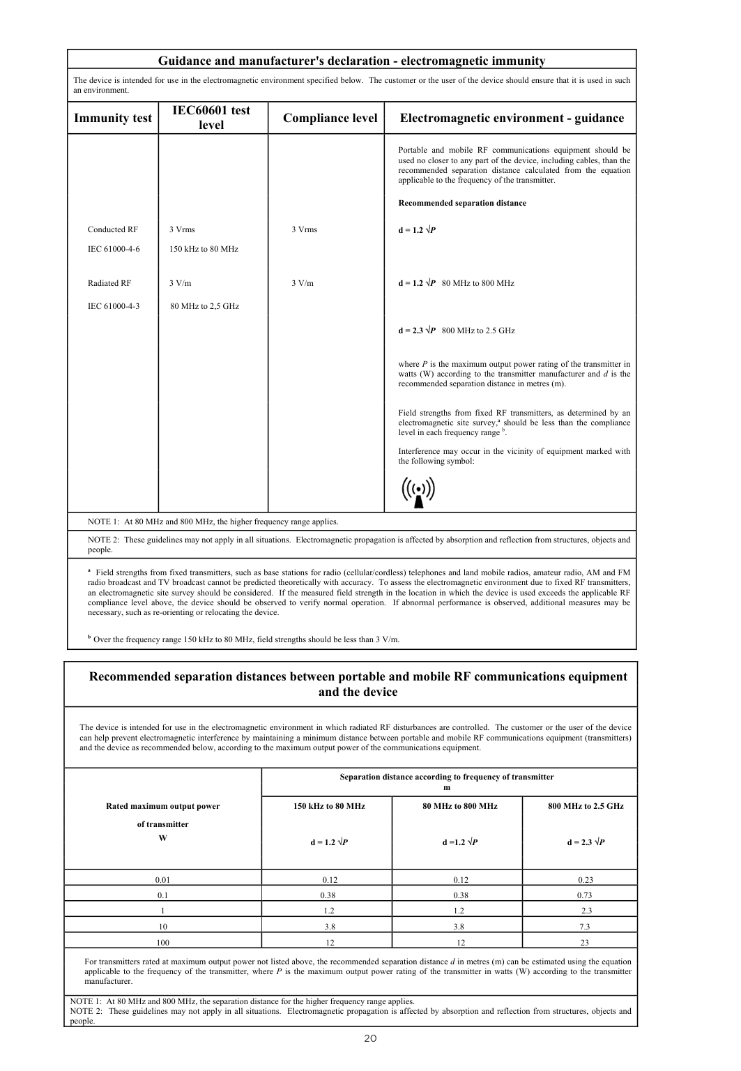
|Guidance and manufacturer's declaration - electromagnetic immunity|Guidance and manufacturer's declaration - electromagnetic immunity|Guidance and manufacturer's declaration - electromagnetic immunity|Guidance and manufacturer's declaration - electromagnetic immunity| |---|---|---|---| |The device is intended for use in the electromagnetic environment specified below. The customer or the user of the device should ensure that it is used in such an environment.|The device is intended for use in the electromagnetic environment specified below. The customer or the user of the device should ensure that it is used in such an environment.|The device is intended for use in the electromagnetic environment specified below. The customer or the user of the device should ensure that it is used in such an environment.|The device is intended for use in the electromagnetic environment specified below. The customer or the user of the device should ensure that it is used in such an environment.| |Immunity test|IEC60601 test level|Compliance level
|Electromagnetic environment - guidance| |Conducted RF IEC 61000-4-6
Radiated RF
IEC 61000-4-3|3 Vrms 150 kHz to 80 MHz
3 V/m
80 MHz to 2,5 GHz|3 Vrms
3 V/m|Portable and mobile RF communications equipment should be used no closer to any part of the device, including cables, than the recommended separation distance calculated from the equation applicable to the frequency of the transmitter.
Recommended separation distance
d = 1.2 √P
d = 1.2 √P 80 MHz to 800 MHz
d = 2.3 √P 800 MHz to 2.5 GHz
where P is the maximum output power rating of the transmitter in watts (W) according to the transmitter manufacturer and d is the recommended separation distance in metres (m).
Field strengths from fixed RF transmitters, as determined by an electromagnetic site survey,ª should be less than the compliance level in each frequency range b.
Interference may occur in the vicinity of equipment marked with the following symbol:
| |NOTE 1: At 80 MHz and 800 MHz, the higher frequency range applies.|NOTE 1: At 80 MHz and 800 MHz, the higher frequency range applies.|NOTE 1: At 80 MHz and 800 MHz, the higher frequency range applies.|NOTE 1: At 80 MHz and 800 MHz, the higher frequency range applies.| |NOTE 2: These guidelines may not apply in all situations. Electromagnetic propagation is affected by absorption and reflection from structures, objects and people.|NOTE 2: These guidelines may not apply in all situations. Electromagnetic propagation is affected by absorption and reflection from structures, objects and people.|NOTE 2: These guidelines may not apply in all situations. Electromagnetic propagation is affected by absorption and reflection from structures, objects and people.|NOTE 2: These guidelines may not apply in all situations. Electromagnetic propagation is affected by absorption and reflection from structures, objects and people.| |a Field strengths from fixed transmitters, such as base stations for radio (cellular/cordless) telephones and land mobile radios, amateur radio, AM and FM radio broadcast and TV broadcast cannot be predicted theoretically with accuracy. To assess the electromagnetic environment due to fixed RF transmitters, an electromagnetic site survey should be considered. If the measured field strength in the location in which the device is used exceeds the applicable RF compliance level above, the device should be observed to verify normal operation. If abnormal performance is observed, additional measures may be necessary, such as re-orienting or relocating the device.
b Over the frequency range 150 kHz to 80 MHz, field strengths should be less than 3 V/m.17 of 17
|a Field strengths from fixed transmitters, such as base stations for radio (cellular/cordless) telephones and land mobile radios, amateur radio, AM and FM radio broadcast and TV broadcast cannot be predicted theoretically with accuracy. To assess the electromagnetic environment due to fixed RF transmitters, an electromagnetic site survey should be considered. If the measured field strength in the location in which the device is used exceeds the applicable RF compliance level above, the device should be observed to verify normal operation. If abnormal performance is observed, additional measures may be necessary, such as re-orienting or relocating the device.
b Over the frequency range 150 kHz to 80 MHz, field strengths should be less than 3 V/m.17 of 17
|
|Recommended separation distances between portable and mobile RF communications equipment and the device
|Recommended separation distances between portable and mobile RF communications equipment and the device
|Recommended separation distances between portable and mobile RF communications equipment and the device
|Recommended separation distances between portable and mobile RF communications equipment and the device
| |---|---|---|---| |The device is intended for use in the electromagnetic environment in which radiated RF disturbances are controlled. The customer or the user of the device can help prevent electromagnetic interference by maintaining a minimum distance between portable and mobile RF communications equipment (transmitters) and the device as recommended below, according to the maximum output power of the communications equipment.|The device is intended for use in the electromagnetic environment in which radiated RF disturbances are controlled. The customer or the user of the device can help prevent electromagnetic interference by maintaining a minimum distance between portable and mobile RF communications equipment (transmitters) and the device as recommended below, according to the maximum output power of the communications equipment.|The device is intended for use in the electromagnetic environment in which radiated RF disturbances are controlled. The customer or the user of the device can help prevent electromagnetic interference by maintaining a minimum distance between portable and mobile RF communications equipment (transmitters) and the device as recommended below, according to the maximum output power of the communications equipment.|The device is intended for use in the electromagnetic environment in which radiated RF disturbances are controlled. The customer or the user of the device can help prevent electromagnetic interference by maintaining a minimum distance between portable and mobile RF communications equipment (transmitters) and the device as recommended below, according to the maximum output power of the communications equipment.| |TechnRated maximum output power
of transmitter W
|Series Humidifiers Models PT101 and PT100
Separation distance according to frequency of transmitter m|Series Humidifiers Models PT101 and PT100
Separation distance according to frequency of transmitter m|Series Humidifiers Models PT101 and PT100
Separation distance according to frequency of transmitter m| |TechnRated maximum output power
of transmitter W
|cal Manual Rev D (Part Num150 kHz to 80 MHz
d = 1.2 √P
|er 185044926)80 MHz to 800 MHz
d =1.2 √P
|800 MHz to 2.5 GHz
d = 2.3 √P
|
|0.01|0.12|0.12|0.23| |0.1|0.38|0.38|0.73| |1|1.2|1.2|2.3| |10|3.8|3.8|7.3| |100|12|12|23| |For transmitters rated at maximum output power not listed above, the recommended separation distance d in metres (m) can be estimated using the equation applicable to the frequency of the transmitter, where P is the maximum output power rating of the transmitter in watts (W) according to the transmitter manufacturer.
|For transmitters rated at maximum output power not listed above, the recommended separation distance d in metres (m) can be estimated using the equation applicable to the frequency of the transmitter, where P is the maximum output power rating of the transmitter in watts (W) according to the transmitter manufacturer.
|For transmitters rated at maximum output power not listed above, the recommended separation distance d in metres (m) can be estimated using the equation applicable to the frequency of the transmitter, where P is the maximum output power rating of the transmitter in watts (W) according to the transmitter manufacturer.
|For transmitters rated at maximum output power not listed above, the recommended separation distance d in metres (m) can be estimated using the equation applicable to the frequency of the transmitter, where P is the maximum output power rating of the transmitter in watts (W) according to the transmitter manufacturer.
| |NOTE 1: At 80 MHz and 800 MHz, the separation distance for the higher frequency range applies.
NOTE 2: These guidelines may not apply in all situations. Electromagnetic propagation is affected by absorption and reflection from structures, objects and people.
|NOTE 1: At 80 MHz and 800 MHz, the separation distance for the higher frequency range applies.
NOTE 2: These guidelines may not apply in all situations. Electromagnetic propagation is affected by absorption and reflection from structures, objects and people.
|NOTE 1: At 80 MHz and 800 MHz, the separation distance for the higher frequency range applies.
NOTE 2: These guidelines may not apply in all situations. Electromagnetic propagation is affected by absorption and reflection from structures, objects and people.
|NOTE 1: At 80 MHz and 800 MHz, the separation distance for the higher frequency range applies.
NOTE 2: These guidelines may not apply in all situations. Electromagnetic propagation is affected by absorption and reflection from structures, objects and people.
|
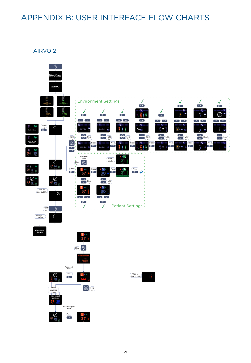
APPENDIX B: USER INTERFACE FLOW CHARTS
######### AIRVO 2

| |
| |---|---| |17 days 14 hours|17 days 14 hours| | | |


Environment Settings


Last Disinfection: #4
Last Disinfection: #5


2 days 4 hours
90
25
34


95%


agoago

2
21
34


Hold 5 s


60
90
37

60


100%


30

AIRVO 2

English


Junior Mode

31
10
21
10
V6.72


Hold 3s
Hold 3s
Hold 3s
Hold 3s
Hold
Hold 3s
Hold 3s
Hold 3s
Hold 3s
5 s New Target Settings


Press
Press Press Press Press PressPress


60 25
90 90
37
34


100%


30


AIRVO 2
English


31
10 2
34
21
21


Transport Mode


After 3 scrolls

90


Hold 5 s
21

Press
Press
Press
Press


90


21 onitor patient O2


Hold 3s
Hold 3s


Wait for time out 60s


37 60


31 10


Patient Settings


Hold 3s
Oxygen is left on


Disconnect Oxygen


Hold 5 s

Transport Mode
Press

Wait for time out 60s


19:55 19:23

timer reaches 00:00
Hold 5 s

Non-Transport Mode


Press


21
| | | |---|---| | | |


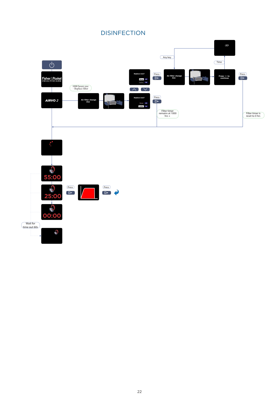
######### DISINFECTION
Any key

Time
1000 hours use - Replace filter


Press Press


Now
Later


Press

Now
Later
Filter timer remains at 1000 hrs +
Filter timer is reset to 0 hrs


Press Press


Wait for time out 60s

| | | |---|---| | | |
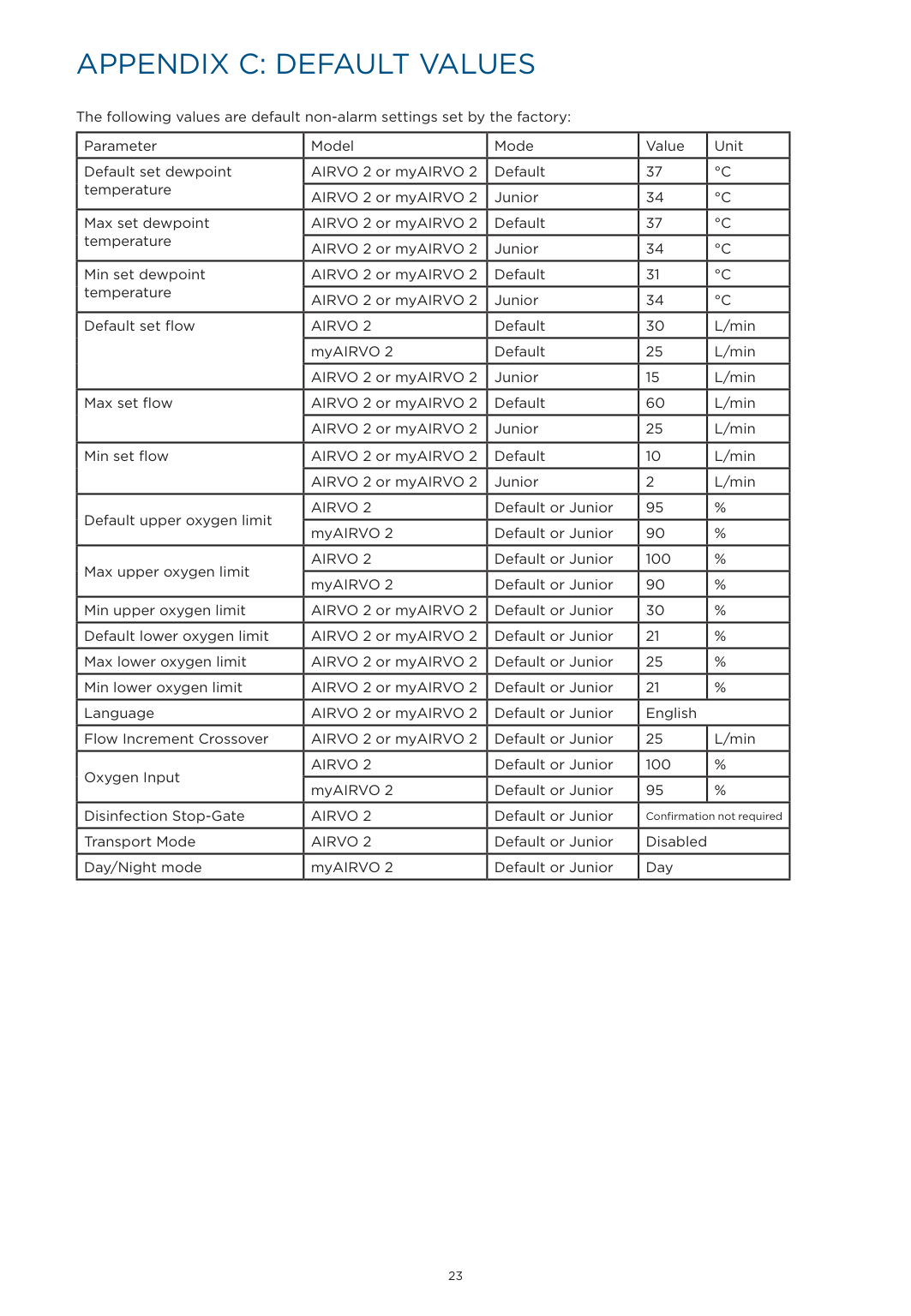
APPENDIX C: DEFAULT VALUES
The following values are default non-alarm settings set by the factory:
|Parameter|Model|Mode|Value|Unit| |---|---|---|---|---| |Default set dewpoint temperature|AIRVO 2 or myAIRVO 2|Default|37|°C| |Default set dewpoint temperature|AIRVO 2 or myAIRVO 2|Junior|34|°C| |Max set dewpoint temperature|AIRVO 2 or myAIRVO 2|Default|37|°C| |Max set dewpoint temperature|AIRVO 2 or myAIRVO 2|Junior|34|°C| |Min set dewpoint temperature|AIRVO 2 or myAIRVO 2|Default|31|°C| |Min set dewpoint temperature|AIRVO 2 or myAIRVO 2|Junior|34|°C| |Default set flow|AIRVO 2|Default|30|L/min| |Default set flow|myAIRVO 2|Default|25|L/min| |Default set flow|AIRVO 2 or myAIRVO 2|Junior|15|L/min| |Max set flow|AIRVO 2 or myAIRVO 2|Default|60|L/min| |Max set flow|AIRVO 2 or myAIRVO 2|Junior|25|L/min| |Min set flow|AIRVO 2 or myAIRVO 2|Default|10|L/min| |Min set flow|AIRVO 2 or myAIRVO 2|Junior|2|L/min| |Default upper oxygen limit|AIRVO 2|Default or Junior|95|%| |Default upper oxygen limit|myAIRVO 2|Default or Junior|90|%| |Max upper oxygen limit|AIRVO 2|Default or Junior|100|%| |Max upper oxygen limit|myAIRVO 2|Default or Junior|90|%| |Min upper oxygen limit|AIRVO 2 or myAIRVO 2|Default or Junior|30|%| |Default lower oxygen limit|AIRVO 2 or myAIRVO 2|Default or Junior|21|%| |Max lower oxygen limit|AIRVO 2 or myAIRVO 2|Default or Junior|25|%| |Min lower oxygen limit|AIRVO 2 or myAIRVO 2|Default or Junior|21|%| |Language|AIRVO 2 or myAIRVO 2|Default or Junior|English|English| |Flow Increment Crossover|AIRVO 2 or myAIRVO 2|Default or Junior|25|L/min| |Oxygen Input|AIRVO 2|Default or Junior|100|%| |Oxygen Input|myAIRVO 2|Default or Junior|95|%| |Disinfection Stop-Gate|AIRVO 2|Default or Junior|Confirmation not required|Confirmation not required| |Transport Mode|AIRVO 2|Default or Junior|Disabled|Disabled| |Day/Night mode|myAIRVO 2|Default or Junior|Day|Day|
| | | |---|---| | | |
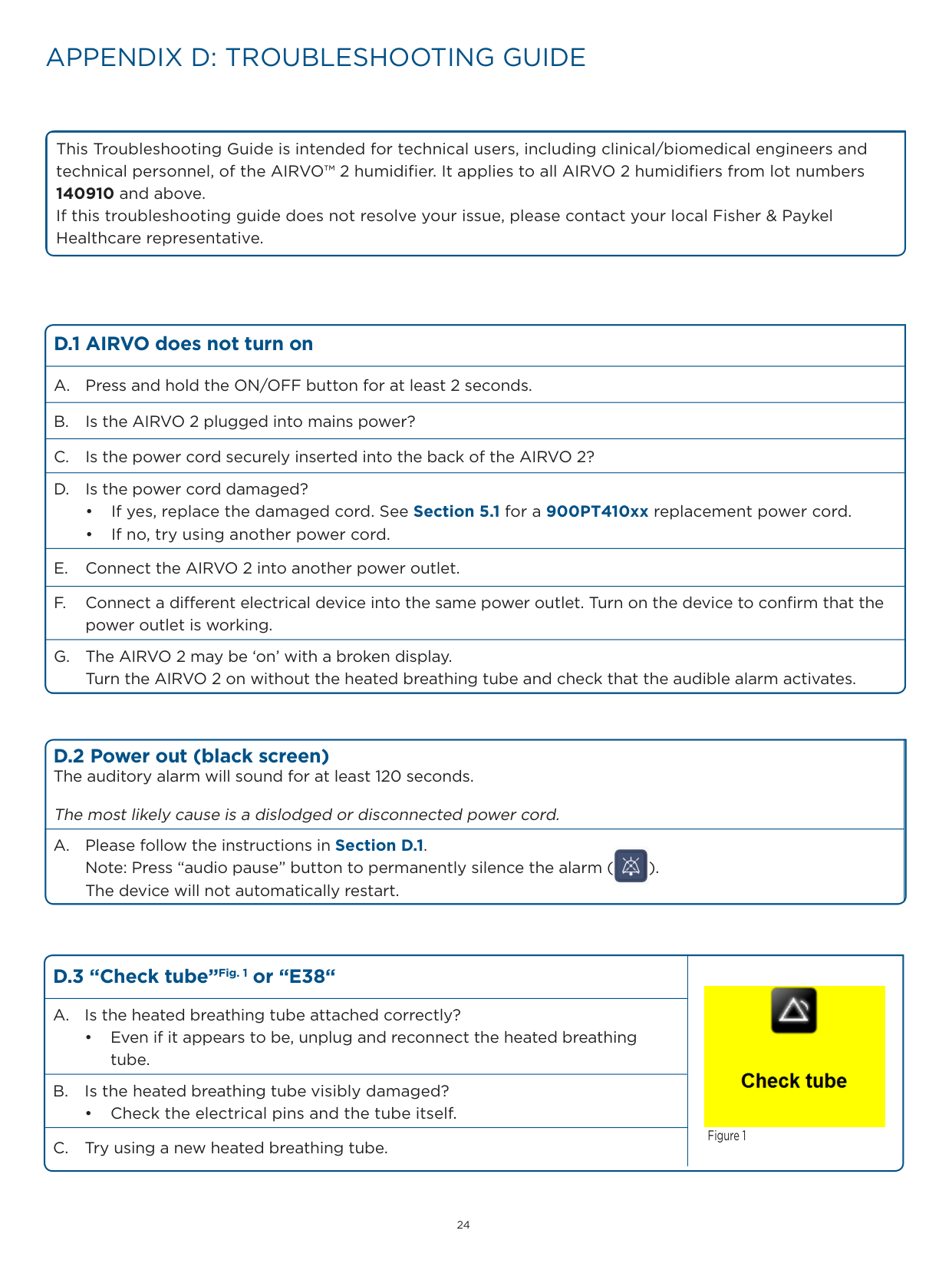
APPENDIX D: TROUBLESHOOTING GUIDE
This Troubleshooting Guide is intended for technical users, including clinical/biomedical engineers and technical personnel, of the AIRVO™ 2 humidifier. It applies to all AIRVO 2 humidifiers from lot numbers 140910 and above.
If this troubleshooting guide does not resolve your issue, please contact your local Fisher & Paykel Healthcare representative.
###### D.1 AIRVO does not turn on
######## D.2 Power out (black screen)The auditory alarm will sound for at least 120 seconds.
The most likely cause is a dislodged or disconnected power cord. A. Please follow the instructions in Section D.1.

Note: Press “audio pause” button to permanently silence the alarm ( ). The device will not automatically restart.
|D.3 “Check tube”Fig. 1 or “E38“|
Figure 1| |---|---| |A. Is the heated breathing tube attached correctly?
• Even if it appears to be, unplug and reconnect the heated breathing tube.|
Figure 1| |B. Is the heated breathing tube visibly damaged?
• Check the electrical pins and the tube itself.|
Figure 1| |C. Try using a new heated breathing tube.|
Figure 1|
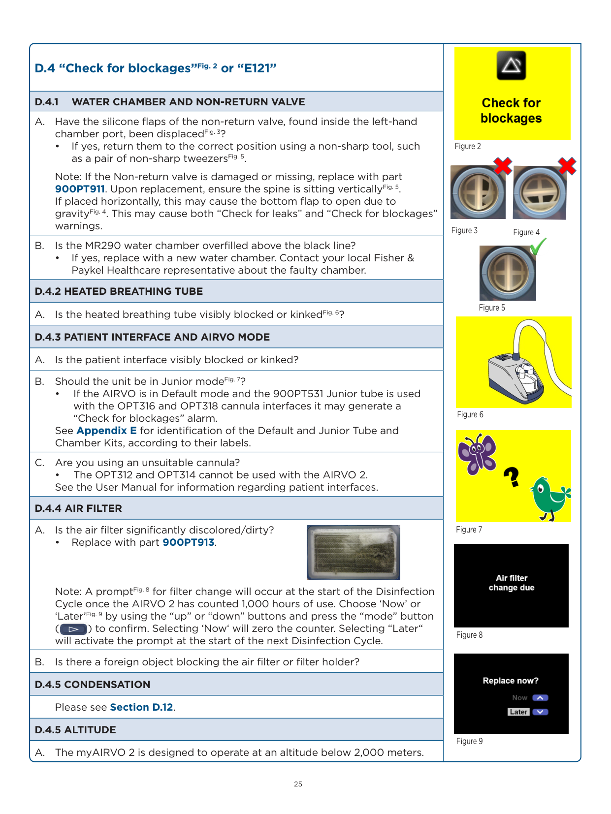
|D.4 “Check for blockages”Fig. 2 or “E121”|


Figure 2


Figure 3 Figure 4

Figure 7

Figure 8

Figure 9
Figure 5

Figure 6| |---|---| |D.4.1 WATER CHAMBER AND NON-RETURN VALVE|


Figure 2


Figure 3 Figure 4

Figure 7

Figure 8

Figure 9
Figure 5

Figure 6| |A. Have the silicone flaps of the non-return valve, found inside the left-hand chamber port, been displacedFig. 3?
• If yes, return them to the correct position using a non-sharp tool, such as a pair of non-sharp tweezersFig. 5.
Note: If the Non-return valve is damaged or missing, replace with part 900PT911. Upon replacement, ensure the spine is sitting verticallyFig. 5. If placed horizontally, this may cause the bottom flap to open due to gravityFig. 4. This may cause both “Check for leaks” and “Check for blockages” warnings.|


Figure 2


Figure 3 Figure 4

Figure 7

Figure 8

Figure 9
Figure 5

Figure 6| |B. Is the MR290 water chamber overfilled above the black line?
• If yes, replace with a new water chamber. Contact your local Fisher & Paykel Healthcare representative about the faulty chamber.|


Figure 2


Figure 3 Figure 4

Figure 7

Figure 8

Figure 9
Figure 5

Figure 6| |D.4.2 HEATED BREATHING TUBE|


Figure 2


Figure 3 Figure 4

Figure 7

Figure 8

Figure 9
Figure 5

Figure 6| |A. Is the heated breathing tube visibly blocked or kinkedFig. 6?|


Figure 2


Figure 3 Figure 4

Figure 7

Figure 8

Figure 9
Figure 5

Figure 6| |D.4.3 PATIENT INTERFACE AND AIRVO MODE|


Figure 2


Figure 3 Figure 4

Figure 7

Figure 8

Figure 9
Figure 5

Figure 6| |A. Is the patient interface visibly blocked or kinked?|


Figure 2


Figure 3 Figure 4

Figure 7

Figure 8

Figure 9
Figure 5

Figure 6| |B. Should the unit be in Junior modeFig. 7?
• If the AIRVO is in Default mode and the 900PT531 Junior tube is used with the OPT316 and OPT318 cannula interfaces it may generate a “Check for blockages” alarm.
See Appendix E for identification of the Default and Junior Tube and Chamber Kits, according to their labels.
|


Figure 2


Figure 3 Figure 4

Figure 7

Figure 8

Figure 9
Figure 5

Figure 6| |C. Are you using an unsuitable cannula?
• The OPT312 and OPT314 cannot be used with the AIRVO 2. See the User Manual for information regarding patient interfaces.|


Figure 2


Figure 3 Figure 4

Figure 7

Figure 8

Figure 9
Figure 5

Figure 6| |D.4.4 AIR FILTER|


Figure 2


Figure 3 Figure 4

Figure 7

Figure 8

Figure 9
Figure 5

Figure 6| |A. Is the air filter significantly discolored/dirty?
• Replace with part 900PT913.
Note: A promptFig. 8 for filter change will occur at the start of the Disinfection Cycle once the AIRVO 2 has counted 1,000 hours of use. Choose ‘Now’ or ‘Later’Fig. 9 by using the “up” or “down” buttons and press the “mode” button ( ) to confirm. Selecting ‘Now‘ will zero the counter. Selecting “Later“ will activate the prompt at the start of the next Disinfection Cycle.

|


Figure 2


Figure 3 Figure 4

Figure 7

Figure 8

Figure 9
Figure 5

Figure 6| |B. Is there a foreign object blocking the air filter or filter holder?|


Figure 2


Figure 3 Figure 4

Figure 7

Figure 8

Figure 9
Figure 5

Figure 6| |D.4.5 CONDENSATION|


Figure 2


Figure 3 Figure 4

Figure 7

Figure 8

Figure 9
Figure 5

Figure 6| |Please see Section D.12.|


Figure 2


Figure 3 Figure 4

Figure 7

Figure 8

Figure 9
Figure 5

Figure 6| |D.4.5 ALTITUDE|


Figure 2


Figure 3 Figure 4

Figure 7

Figure 8

Figure 9
Figure 5

Figure 6| |A. The myAIRVO 2 is designed to operate at an altitude below 2,000 meters.|


Figure 2


Figure 3 Figure 4

Figure 7

Figure 8

Figure 9
Figure 5

Figure 6|
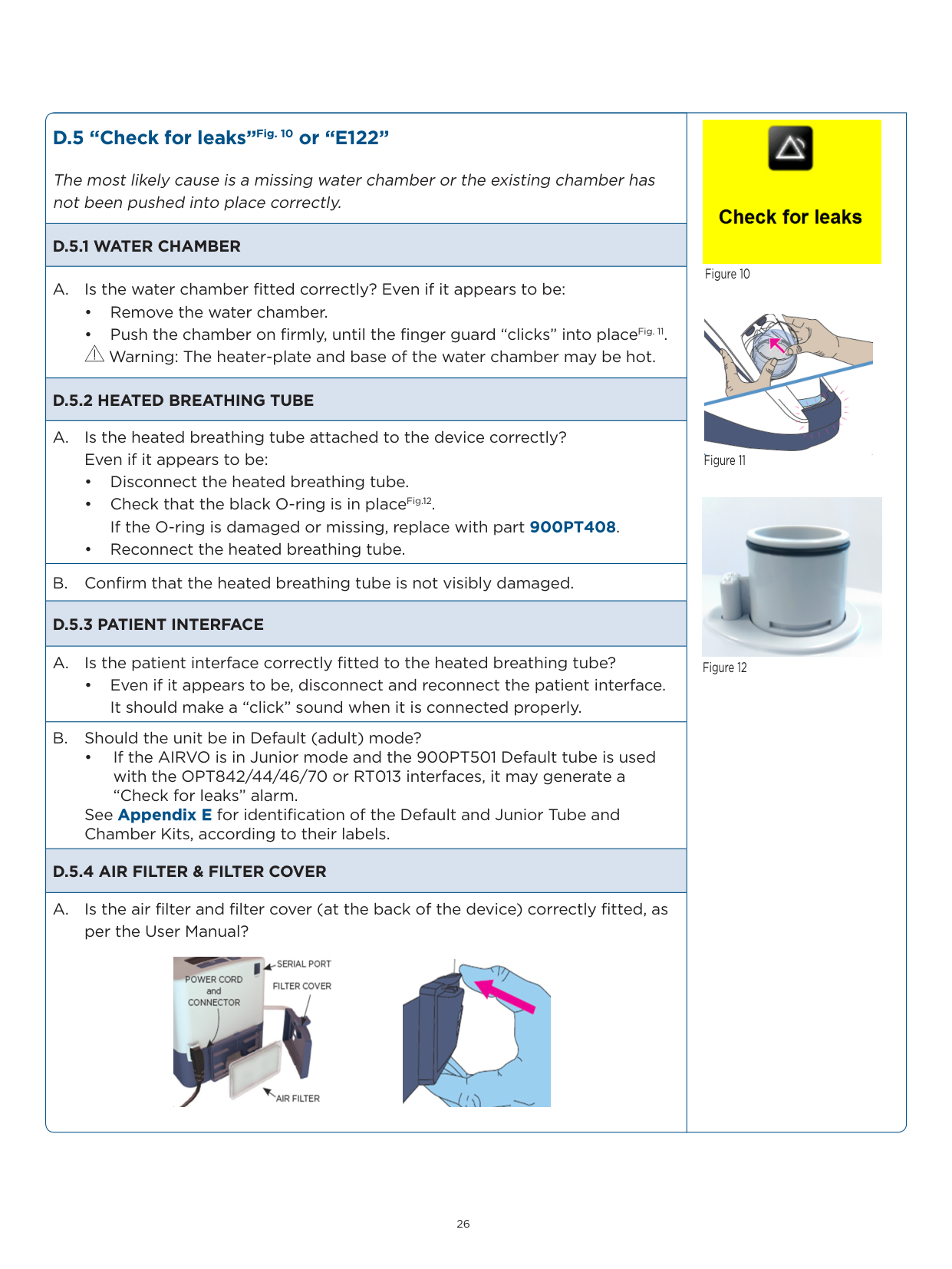
###### D.5 “Check for leaks”Fig. 10 or “E122”
The most likely cause is a missing water chamber or the existing chamber has not been pushed into place correctly.
########## D.5.1 WATER CHAMBER
A. Is the water chamber fitted correctly? Even if it appears to be:
Warning: The heater-plate and base of the water chamber may be hot.
########## D.5.2 HEATED BREATHING TUBE
########## D.5.3 PATIENT INTERFACE
• Even if it appears to be, disconnect and reconnect the patient interface. It should make a “click” sound when it is connected properly.
• If the AIRVO is in Junior mode and the 900PT501 Default tube is used with the OPT842/44/46/70 or RT013 interfaces, it may generate a “Check for leaks” alarm.
See Appendix E for identification of the Default and Junior Tube and Chamber Kits, according to their labels.
########## D.5.4 AIR FILTER & FILTER COVER
A. Is the air filter and filter cover (at the back of the device) correctly fitted, as per the User Manual?


Figure 10


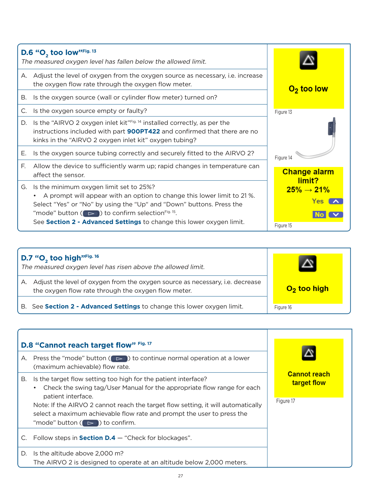
######## D.6 “O2 too low”Fig. 13The measured oxygen level has fallen below the allowed limit.
• A prompt will appear with an option to change this lower limit to 21 %. Select “Yes” or “No” by using the “Up“ and “Down” buttons. Press the “mode” button ( ) to confirm selectionFig. 15. See Section 2 - Advanced Settings to change this lower oxygen limit.
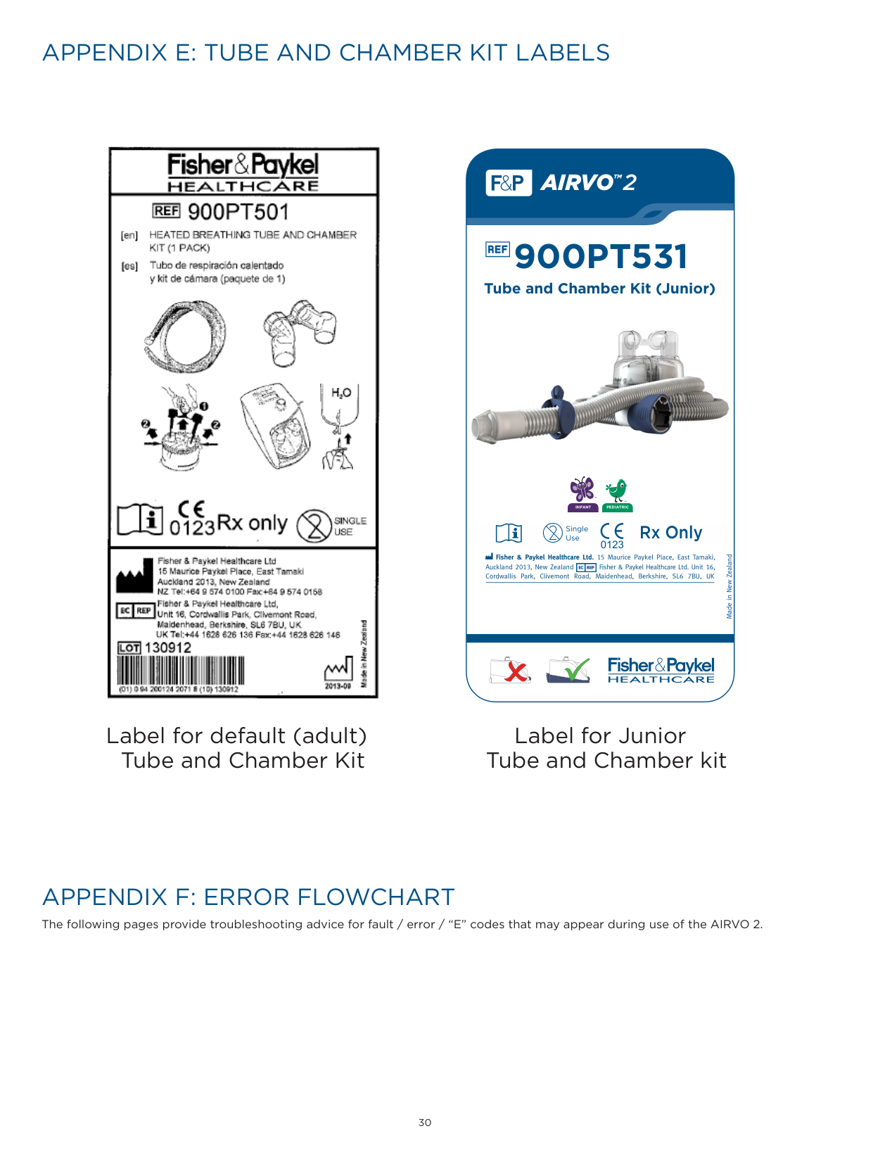


Figure 13


######## D.7 “O2 too high”Fig. 16The measured oxygen level has risen above the allowed limit.

|D.8 “Cannot reach target flow” Fig. 17|
Figure 17| |---|---| |A. Press the “mode” button ( ) to continue normal operation at a lower (maximum achievable) flow rate.
|
Figure 17| |B. Is the target flow setting too high for the patient interface?
• Check the swing tag/User Manual for the appropriate flow range for each
patient interface. Note: If the AIRVO 2 cannot reach the target flow setting, it will automatically select a maximum achievable flow rate and prompt the user to press the “mode” button ( ) to confirm.
|
Figure 17| |C. Follow steps in Section D.4 — “Check for blockages”.|
Figure 17| |D. Is the altitude above 2,000 m? The AIRVO 2 is designed to operate at an altitude below 2,000 meters.|
Figure 17|
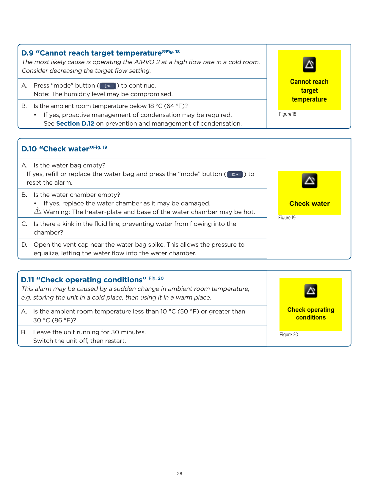
|D.9 “Cannot reach target temperature”Fig. 18 The most likely cause is operating the AIRVO 2 at a high flow rate in a cold room. Consider decreasing the target flow setting.|
Figure 18| |---|---| |A. Press “mode” button ( ) to continue. Note: The humidity level may be compromised.
|
Figure 18| |B. Is the ambient room temperature below 18 °C (64 °F)?
• If yes, proactive management of condensation may be required. See Section D.12 on prevention and management of condensation.|
Figure 18|
|D.10 “Check water”Fig. 19|
Figure 19| |---|---| |A. Is the water bag empty? If yes, refill or replace the water bag and press the “mode” button ( ) to reset the alarm.
|
Figure 19| |B. Is the water chamber empty?
• If yes, replace the water chamber as it may be damaged.
Warning: The heater-plate and base of the water chamber may be hot.|
Figure 19| |C. Is there a kink in the fluid line, preventing water from flowing into the chamber?|
Figure 19| |D. Open the vent cap near the water bag spike. This allows the pressure to equalize, letting the water flow into the water chamber.|
Figure 19|
|D.11 “Check operating conditions” Fig. 20 This alarm may be caused by a sudden change in ambient room temperature, e.g. storing the unit in a cold place, then using it in a warm place.|
Figure 20| |---|---| |A. Is the ambient room temperature less than 10 °C (50 °F) or greater than 30 °C (86 °F)?|
Figure 20| |B. Leave the unit running for 30 minutes. Switch the unit off, then restart.|
Figure 20|
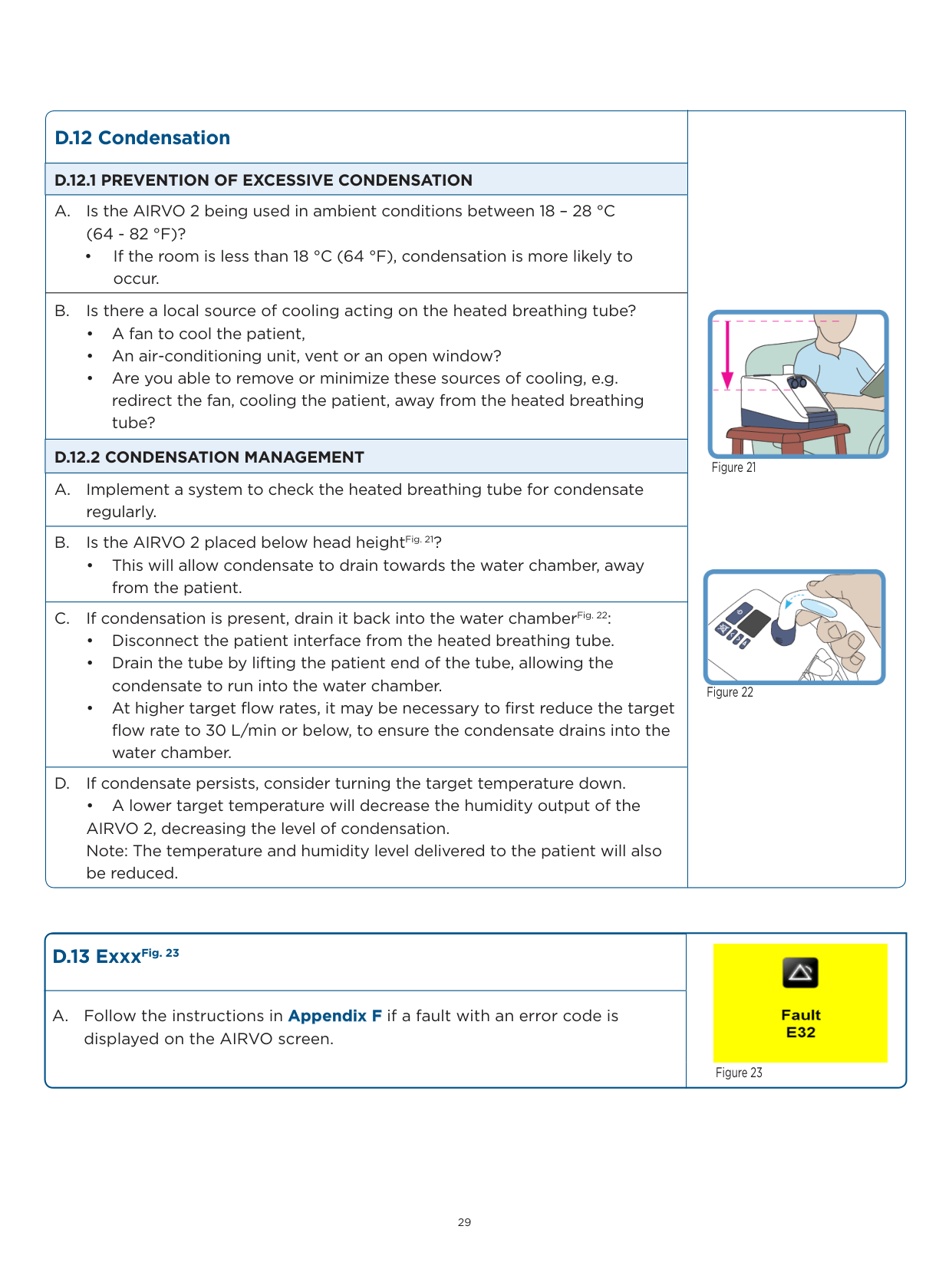
|D.12 Condensation|
Figure 21

Figure 22
| |---|---| |D.12.1 PREVENTION OF EXCESSIVE CONDENSATION|
Figure 21

Figure 22
| |A. Is the AIRVO 2 being used in ambient conditions between 18 – 28 °C (64 - 82 °F)?
• If the room is less than 18 °C (64 °F), condensation is more likely to occur.|
Figure 21

Figure 22
| |B. Is there a local source of cooling acting on the heated breathing tube?
• A fan to cool the patient,
• An air-conditioning unit, vent or an open window?
• Are you able to remove or minimize these sources of cooling, e.g. redirect the fan, cooling the patient, away from the heated breathing tube?
|
Figure 21

Figure 22
| |D.12.2 CONDENSATION MANAGEMENT|
Figure 21

Figure 22
| |A. Implement a system to check the heated breathing tube for condensate regularly.|
Figure 21

Figure 22
| |B. Is the AIRVO 2 placed below head heightFig. 21?
• This will allow condensate to drain towards the water chamber, away from the patient.|
Figure 21

Figure 22
| |C. If condensation is present, drain it back into the water chamberFig. 22:
• Disconnect the patient interface from the heated breathing tube.
• Drain the tube by lifting the patient end of the tube, allowing the condensate to run into the water chamber.
• At higher target flow rates, it may be necessary to first reduce the target flow rate to 30 L/min or below, to ensure the condensate drains into the water chamber.
|
Figure 21

Figure 22
|
|D. If condensate persists, consider turning the target temperature down.
• A lower target temperature will decrease the humidity output of the AIRVO 2, decreasing the level of condensation. Note: The temperature and humidity level delivered to the patient will also be reduced.|
Figure 21

Figure 22
|
###### D.13 ExxxFig. 23
A. Follow the instructions in Appendix F if a fault with an error code is displayed on the AIRVO screen.

Figure 23

#### AIRVO
2
TM
900PT531

Tube and Chamber Kit (Junior)

################### PEDIATRICINFANT
##### Rx Only
Single Use
0123
Fisher & Paykel Healthcare Ltd. 15 Maurice Paykel Place, East Tamaki, Auckland 2013, New Zealand Fisher & Paykel Healthcare Ltd. Unit 16, Cordwallis Park, Clivemont Road, Maidenhead, Berkshire, SL6 7BU, UK
Made in New Zealand

| | | |---|---| | | |
| | | |---|---| | | |
Label for default (adult) Tube and Chamber Kit
Label for Junior Tube and Chamber kit
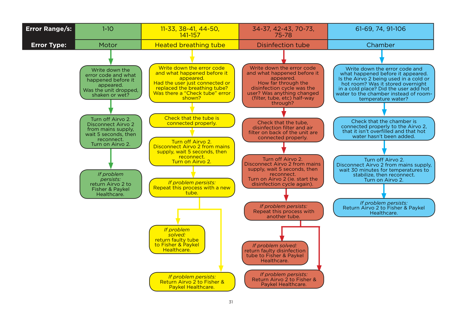
The following pages provide troubleshooting advice for fault / error / “E” codes that may appear during use of the AIRVO 2.
|Error Range/s:|1-10|1-10|11-33, 38-41, 44-50, 141-157|11-33, 38-41, 44-50, 141-157|34-37, 42-43, 70-73, 75-78|61-69, 74, 91-106|61-69, 74, 91-106| |---|---|---|---|---|---|---|---| |Error Type:|Mot|r|Heated breathing tube|Heated breathing tube|Disinfection tube|Chamber|Chamber| | | | | | | | | |
Write down the error code and what happened before it appeared. Had the user just connected or replaced the breathing tube? Was there a “Check tube” error shown?
Write down the error code and what happened before it appeared. How far through the disinfection cycle was the user? Was anything changed (filter, tube, etc) half-way through?
Write down the error code and what happened before it appeared. Is the Airvo 2 being used in a cold or hot room? Was it stored overnight in a cold place? Did the user add hot water to the chamber instead of roomtemperature water?
Write down the error code and what happened before it appeared. Was the unit dropped, shaken or wet?
Check that the tube is connected properly.
Turn off Airvo 2. Disconnect Airvo 2 from mains supply, wait 5 seconds, then reconnect. Turn on Airvo 2.
Check that the chamber is connected properly to the Airvo 2, that it isn’t overfilled and that hot water hasn’t been added.
Check that the tube, disinfection filter and air filter on back of the unit are connected properly.
Turn off Airvo 2. Disconnect Airvo 2 from mains supply, wait 5 seconds, then reconnect. Turn on Airvo 2.
Turn off Airvo 2. Disconnect Airvo 2 from mains supply, wait 5 seconds, then reconnect. Turn on Airvo 2 (ie. start the disinfection cycle again).
Turn off Airvo 2. Disconnect Airvo 2 from mains supply, wait 30 minutes for temperatures to stabilize, then reconnect. Turn on Airvo 2.
If problem persists: return Airvo 2 to Fisher & Paykel Healthcare.
If problem persists: Repeat this process with a new tube.
If problem persists: Return Airvo 2 to Fisher & Paykel Healthcare.
If problem persists: Repeat this process with another tube.
If problem solved: return faulty tube to Fisher & Paykel Healthcare.
If problem solved: return faulty disinfection tube to Fisher & Paykel Healthcare.
If problem persists: Return Airvo 2 to Fisher & Paykel Healthcare.
If problem persists: Return Airvo 2 to Fisher & Paykel Healthcare.
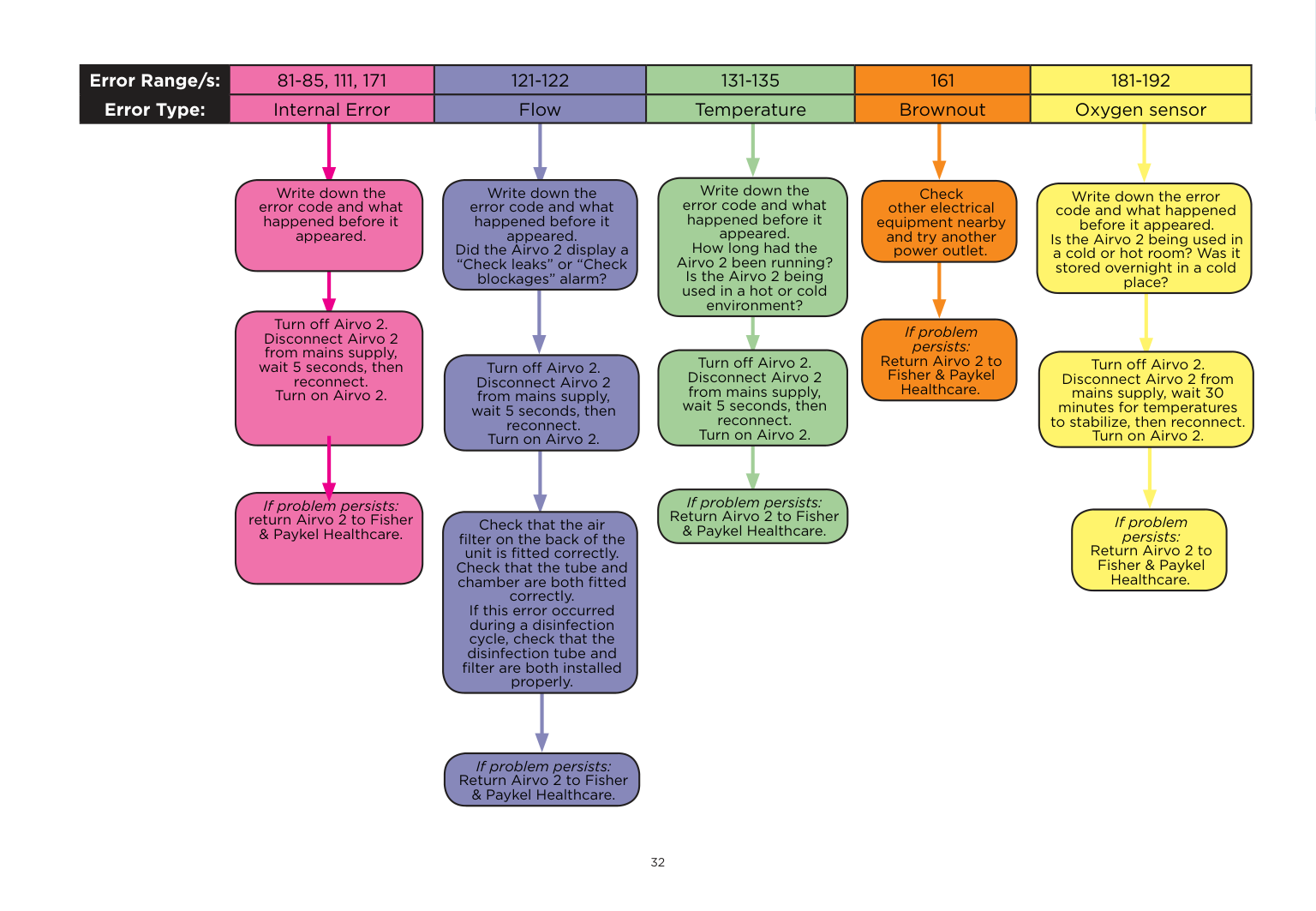
|Error Range/s:|81-85, 111, 171|81-85, 111, 171|121-122|121-122|131-135|131-135|161|161|181-192|181-192| |---|---|---|---|---|---|---|---|---|---|---| |Error Type:|Internal Error|Internal Error|Flow|Flow|Temperature|Temperature|Brownout|Brownout|Oxygen sensor|Oxygen sensor| | | | | | | | | | | | |
Write down the error code and what happened before it appeared. How long had the Airvo 2 been running? Is the Airvo 2 being used in a hot or cold environment?
Write down the error code and what happened before it appeared.
Write down the error code and what happened before it appeared. Did the Airvo 2 display a “Check leaks” or “Check blockages” alarm?
Check other electrical equipment nearby and try another power outlet.
Write down the error code and what happened before it appeared. Is the Airvo 2 being used in a cold or hot room? Was it stored overnight in a cold place?
Turn off Airvo 2. Disconnect Airvo 2 from mains supply, wait 5 seconds, then reconnect. Turn on Airvo 2.
If problem persists: Return Airvo 2 to Fisher & Paykel Healthcare.
Turn off Airvo 2. Disconnect Airvo 2 from mains supply, wait 5 seconds, then reconnect. Turn on Airvo 2.
Turn off Airvo 2. Disconnect Airvo 2 from mains supply, wait 30 minutes for temperatures to stabilize, then reconnect. Turn on Airvo 2.
Turn off Airvo 2. Disconnect Airvo 2 from mains supply, wait 5 seconds, then reconnect. Turn on Airvo 2.
If problem persists: Return Airvo 2 to Fisher & Paykel Healthcare.
If problem persists: return Airvo 2 to Fisher & Paykel Healthcare.
If problem persists: Return Airvo 2 to Fisher & Paykel Healthcare.
Check that the air filter on the back of the unit is fitted correctly. Check that the tube and chamber are both fitted correctly. If this error occurred during a disinfection cycle, check that the disinfection tube and filter are both installed properly.
If problem persists: Return Airvo 2 to Fisher & Paykel Healthcare.
For more information please contact your local Fisher & Paykel Healthcare representative
REF 185047911 REV E © 2014-11 Fisher & Paykel Healthcare Limited
Manufacturer Fisher & Paykel Healthcare Ltd 15 Maurice Paykel Place East Tamaki, Auckland 2013
PO Box 14 348, Panmure Auckland 1741 New Zealand
Tel: +64 9 574 0100 Fax: +64 9 574 0158 Email: [email protected] Web: www.fphcare.com
Australia Fisher & Paykel Healthcare Pty Limited 36-40 New Street, PO Box 167 Ringwood, Melbourne Victoria 3134, Australia Tel: +61 3 9879 5022 Fax: +61 3 9879 5232 Austria Tel: 0800 29 31 23 Fax: 0800 29 31 22 Benelux Tel: +31 40 216 3555 Fax: +31 40 216 3554 China
Tel: +86 20 3205 3486 Fax: +86 20 3205 2132
France Tel: +33 1 6446 5201 Fax: +33 1 6446 5221
Germany Tel: +49 7181 98599 0 Fax: +49 7181 98599 66
############## India
Tel: +91 80 4284 4000 Fax: +91 80 4123 6044
Irish Republic Tel: 1800 409 011
Italy Tel: +39 06 7839 2939 Fax: +39 06 7814 7709
Spain Tel: +34 902 013 346 Fax: +34 902 013 379
Sweden Tel: +46 8 564 76 680 Fax: +46 8 36 63 10
Switzerland Tel: 0800 83 47 63 Fax: 0800 83 47 54
Taiwan Tel: +886 2 8751 1739 Fax: +886 2 8751 5625
Turkey Fisher Paykel Sağlık Ürünleri Ticaret Limited Şirketi, Alinteri Bulvari 1161/1 Sokak No. 12-14, P.O. Box 06371 Ostim, Ankara, Turkey
Tel: +90 312 354 34 12 Fax: +90 312 354 31 01
UK Fisher & Paykel Healthcare Ltd Unit 16, Cordwallis Park Clivemont Road, Maidenhead Berkshire SL6 7BU, UK
Tel: +44 1628 626 136 Fax: +44 1628 626 146
############## USA/Canada
Tel: +1 800 446 3908 or +1 949 453 4000 Fax: +1 949 453 4001
0123
www.fphcare.com