
Ford F 150 2009 2014 Fuses And Fuse Box Diagram And Location
Ask AI
— answers from the official manualAnswers from the official manual.
Common questions
Common Questions
9 totalWhat should I do if I encounter a blinking service engine soon indicator?
A blinking service engine soon light indicates a severe misfire that can cause damage to the catalytic converter, fuel system or other vehicle parts possibly leading to a fire. Drive in a moderate way and seek immediate service by an authorized dealer. (Page 14)
How do I change presets on my satellite radio?
Press and hold the preset button you wish to assign until sound returns and PRESET # SAVED will display, confirming the station has been stored. You can save up to 30 stations in total across AM/FM1/FM2 modes. (Page 24)
What does it mean if my charging system warning light stays on?
The charging system warning light will illuminate when the battery is not charging properly even while the engine is running, indicating a possible malfunction in the system which requires attention as soon as possible. (Page 16)
How do I use my heated seats if the vehicle is equipped with them?
Press the heated seat control button to activate or deactivate the heated seating function. Ensure you find a comfortable temperature setting and press AUTO for full automatic control of heating/cooling levels based on the preset temperatures. (Page 40, page 41)
How do I engage my dual climate control system's pass temperature override?
Press PASS TEMP to activate the separate passenger climate control; you can increase or decrease the airflow and temperature specifically for the front passenger. Refer to Message Center functions detailed in Dual-Zone Climate Control chapter for complete customization. (Page 42)
What happens if my electronic stability control warning light remains illuminated?
An illuminated Advance Trac/Traction Control™ warning signal requires attention immediately, indicating system malfunction or inactivity upon start-up which needs to be addressed by an authorized dealer. (Page 17)
Full Manual
409 pages
##### Introduction 4 Instrument Cluster 12
Warning lights and chimes 12 Gauges 18
##### Entertainment Systems 22
AM/FM stereo 22 AM/FM stereo with CD/MP3 24 Auxiliary input jack (Line in) 32 USB port 34 Satellite radio information 37 Navigation system 40 SYNC 40
##### Climate Controls 41
Manual heating and air conditioning 41 Dual electronic automatic temperature control 44 Navigation system based climate control 49 Rear window defroster 53
##### Lights 54
Headlamps 54 Turn signal control 58 Bulb replacement 59
##### Driver Controls 65
Windshield wiper/washer control 65 Steering wheel adjustment 66 Power windows 72 Mirrors 74 Speed control 80 Message center 89 Tailgate 113
Table of Contents
##### Locks and Security 126
Keys 126 Locks 126 Anti-theft system 139
##### Seating and Safety Restraints 143
Seating 143 Safety restraints 161 Airbags 180 Child restraints 193
##### Tires, Wheels and Loading 216
Tire information 218 Tire inflation 220 Tire Pressure Monitoring System (TPMS) 233 Vehicle loading 244 Trailer towing 250 Trailer brake controller-integrated 257 Recreational towing 263
##### Driving 265
Starting 265 Brakes 272 AdvanceTrac 274 Transmission operation 281 Reverse sensing system 292 Reverse camera 294 Snowplowing 308
##### Roadside Emergencies 312
Getting roadside assistance 312 Hazard flasher control 313 Fuses and relays 314 Changing tires 322 Wheel lug nut torque 330 Jump starting 331 Wrecker towing 337
##### Customer Assistance 339
Reporting safety defects (U.S. only) 345 Reporting safety defects (Canada only) 345
##### Cleaning 346 Maintenance and Specifications 355
Engine compartment 357 Engine oil 360 Battery 363 Engine coolant 365 Fuel information 371 Air filter(s) 389 Part numbers 392 Maintenance product specifications and capacities 393 Engine data 397
##### Accessories 401 Index 403
All rights reserved. Reproduction by any means, electronic or mechanical including photocopying, recording or by any information storage and retrieval system or translation in whole or part is not permitted without written authorization from Ford Motor Company. Ford may change the contents without notice and without incurring obligation.
Copyright © 2009 Ford Motor Company
###### CONGRATULATIONS
Congratulations on acquiring your new Ford Motor Company product. Please take the time to get well acquainted with your vehicle by reading this handbook. The more you know and understand about your vehicle, the greater the safety and pleasure you will derive from driving it.
For more information on Ford Motor Company and its products visit the following website:
This vehicle’s Owner’s Guide describes every option and model variant available and therefore some of the items covered may not apply to your particular vehicle. Furthermore, due to printing cycles it may describe options before they are generally available.
Remember to pass on this vehicle’s Owner’s Guide when reselling the vehicle. It is an integral part of the vehicle.
SAFETY AND ENVIRONMENT PROTECTION
Warning symbols in this guide
How can you reduce the risk of personal injury to yourself or others? In this guide, answers to such questions are contained in comments highlighted by the warning triangle symbol. These comments should be read and observed.
###### Warning symbols on your vehicle
When you see this symbol, it is imperative that you consult the relevant section of this guide before touching or attempting adjustment of any kind.
###### Protecting the environment
We must all play our part in protecting the environment. Correct vehicle usage and the authorized disposal of waste, cleaning and lubrication materials are significant steps towards this aim. Information in this respect is highlighted in this guide with the tree symbol.
###### CALIFORNIA Proposition 65 Warning
WARNING: Engine exhaust, some of its constituents, and certain vehicle components contain or emit chemicals known to
the State of California to cause cancer and birth defects or other reproductive harm. In addition, certain fluids contained in vehicles and certain products of component wear contain or emit chemicals known to the State of California to cause cancer and birth defects or other reproductive harm.
###### PERCHLORATE MATERIAL
Certain components of this vehicle such as airbag modules, seat belt pretensioners, and button cell batteries may contain Perchlorate Material
– Special handling may apply for service or vehicle end of life disposal. See www.dtsc.ca.gov/hazardouswaste/perchlorate.
###### BREAKING-IN YOUR VEHICLE
Your vehicle does not need an extensive break-in. Try not to drive continuously at the same speed for the first 1,000 miles (1,600 km) of new vehicle operation. Vary your speed frequently in order to give the moving parts a chance to break in.
Drive your new vehicle at least 1,000 miles (1,600 km) before towing a trailer. For more detailed information about towing a trailer, refer to Trailer towing in the Tires, Wheels and Loading chapter.
Do not add friction modifier compounds or special break-in oils since these additives may prevent piston ring seating. See Engine oil in the Maintenance and Specifications chapter for more information on oil usage.
SPECIAL NOTICES New Vehicle Limited Warranty
For a detailed description of what is covered and what is not covered by your vehicle’s New Vehicle Limited Warranty, refer to the Warranty Guide/Customer Information Guide that is provided to you along with your Owner’s Guide. Special instructions For your added safety, your vehicle is fitted with sophisticated electronic controls.
WARNING: Please read the section Airbag Supplemental Restraint System (SRS) in the Seating and Safety Restraints
chapter. Failure to follow the specific warnings and instructions could result in personal injury.
WARNING: Front seat mounted rear-facing child or infant seats should NEVER be placed in front of an active passenger airbag.
###### Service Data Recording
Service data recorders in your vehicle are capable of collecting and storing diagnostic information about your vehicle. This potentially includes information about the performance or status of various systems and modules in the vehicle, such as engine, throttle, steering or brake systems. In order to properly diagnose and service your vehicle, Ford Motor Company, Ford of Canada, and service and repair facilities may access vehicle diagnostic information through a direct connection to your vehicle when diagnosing or servicing your vehicle. For U.S. only (if equipped), if you choose to use the SYNC Vehicle Health Report, you consent that certain diagnostic information may also be accessed electronically by Ford Motor Company and Ford authorized service facilities, and that the diagnostic information may be used for any purpose. See your SYNC supplement for more information.
Event Data Recording
Other modules in your vehicle — event data recorders — are capable of collecting and storing data during a crash or near crash event. The recorded information may assist in the investigation of such an event. The modules may record information about both the vehicle and the occupants, potentially including information such as:
To access this information, special equipment must be directly connected to the recording modules. Ford Motor Company and Ford of Canada do not access event data recorder information without obtaining consent, unless pursuant to court order or where required by law enforcement, other government authorities or other third parties acting with lawful authority. Other parties may seek to access the information independently of Ford Motor Company and Ford of Canada. Please note that once 911 Assist (if equipped) is enabled (set ON), 911 Assist may, through any paired and connected cell phone, disclose to emergency services that the vehicle has been in a crash involving the deployment of an airbag or, in certain vehicles, the activation of the fuel pump shut-off. Certain versions or updates to 911 Assist may also be capable of electronically or verbally disclosing to 911 operators the vehicle location, and/or other details about the vehicle or crash to assist 911 operators to provide the most appropriate emergency services. If you do not want to disclose this information, do not activate the feature. See your SYNC supplement for more information.
Using your vehicle with a snowplow
For more information and guidelines for using your vehicle with a snowplow, refer to the Driving chapter.
Using your vehicle as an ambulance Do not use this vehicle as an ambulance.
Your vehicle is not equipped with the Ford Ambulance Preparation Package.
###### Notice to owners of pickup trucks and utility type vehicles
WARNING: Utility vehicles have a significantly higher rollover rate than other types of vehicles.
Before you drive your vehicle, please read this Owner’s Guide carefully. Your vehicle is not a passenger car. As with other vehicles of this type, failure to operate this vehicle correctly may result in loss of vehicle control, vehicle rollover, personal injury or death.
Notice to owners of the F150 Note: Your vehicle is equipped with high performance tires. When first driving the vehicle after it has been parked for a period of time, you may experience a temporary ride disturbance. This is a characteristic of the tires and should be no reason for concern. The condition should correct itself within 5-15 miles (8-25 km) of driving. If the disturbance persists, have the tires serviced by an authorized dealer.
###### Cell phone use
The use of Mobile Communications Equipment has become increasingly important in the conduct of business and personal affairs. However, drivers must not compromise their own or others’ safety when using such equipment. Mobile Communications can enhance personal safety and security when appropriately used, particularly in emergency situations. Safety must be paramount when using mobile communications equipment to avoid negating these benefits.
Mobile Communication Equipment includes, but is not limited to cellular phones, pagers, portable email devices, in-vehicle communications systems, telematics devices and portable two-way radios.
WARNING: Driving while distracted can result in loss of vehicle control, accident and injury. Ford strongly recommends that
drivers use extreme caution when using any device that may take their focus off the road. The driver’s primary responsibility is the safe operation of their vehicle. Only use cell phones and other devices not essential to the driving task when it is safe to do so.
Export unique (Non–United States/Canada) vehicle specific information
For your particular global region, your vehicle may be equipped with features and options that are different from the features and options that are described in this Owner’s Guide. A market unique supplement may be supplied that complements this book. By referring to the market unique supplement, if provided, you can properly identify those features, recommendations and specifications that are unique to your vehicle. This Owner’s Guide is written primarily for the U.S. and Canadian Markets. Features or equipment listed as standard may be different on units built for Export. Refer to this Owner’s Guide for all other required information and warnings.
These are some of the symbols you may see on your vehicle.
###### Vehicle Symbol Glossary
Safety Alert See Owner’s Guide
Fasten Safety Belt Airbag - Front
Airbag - Side
Child Seat Lower Anchor
Child Seat Tether Anchor
Brake System
Anti-Lock Brake System Parking Brake System
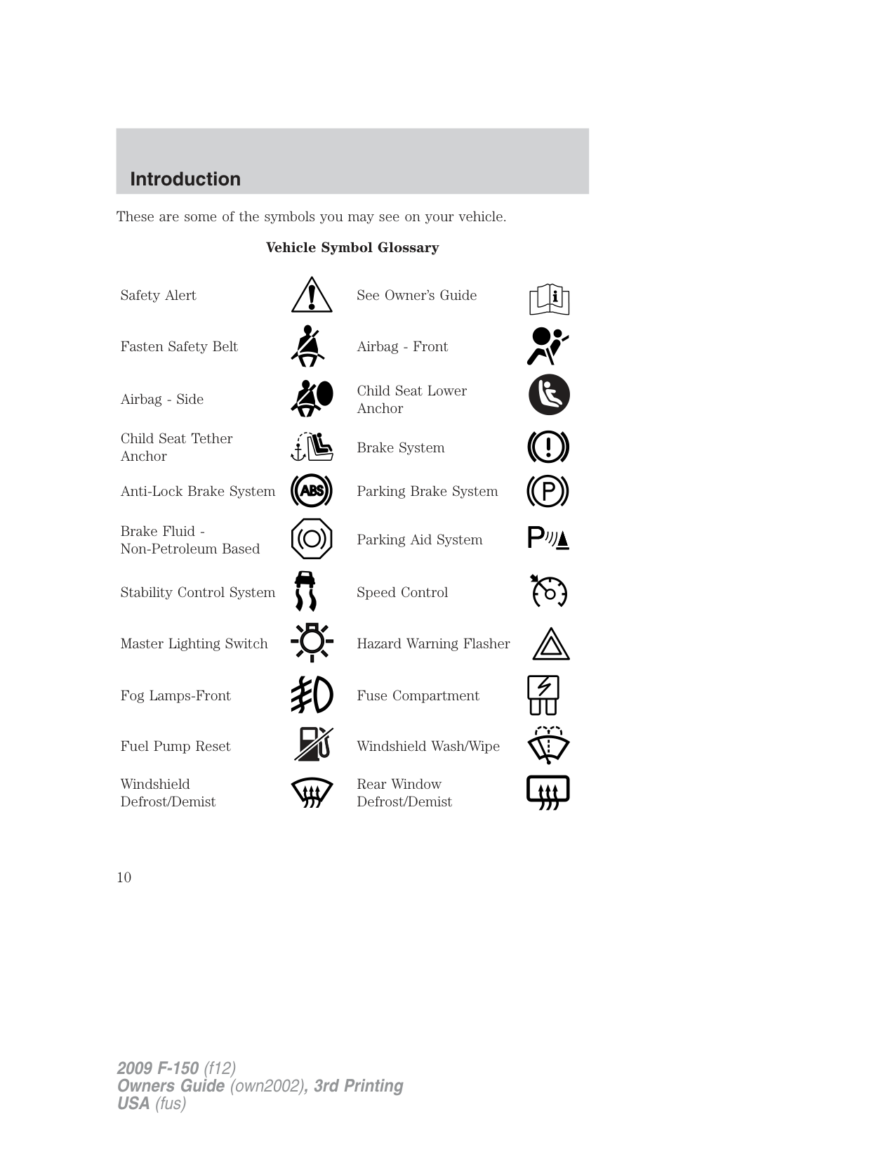
Brake Fluid Non-Petroleum Based
Parking Aid System
Stability Control System Speed Control
Master Lighting Switch Hazard Warning Flasher
Fog Lamps-Front Fuse Compartment
Fuel Pump Reset Windshield Wash/Wipe
Windshield Defrost/Demist
Rear Window Defrost/Demist
###### Vehicle Symbol Glossary
Power Windows Front/Rear
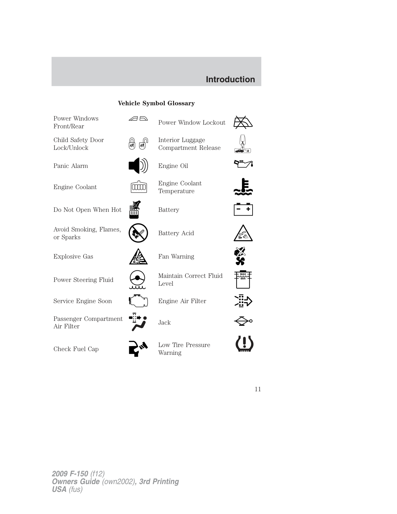
Power Window Lockout
Child Safety Door Lock/Unlock
| | | | |---|---|---| | | | |
| | | |---|---| | | |
Interior Luggage Compartment Release
Panic Alarm Engine Oil
Engine Coolant
Engine Coolant Temperature
Do Not Open When Hot Battery
Avoid Smoking, Flames, or Sparks
Battery Acid
Explosive Gas Fan Warning
Power Steering Fluid
Maintain Correct Fluid Level
Service Engine Soon Engine Air Filter
Passenger Compartment Air Filter
Jack
Check Fuel Cap
Low Tire Pressure Warning
| | |---|
|MAX MIN| |---|
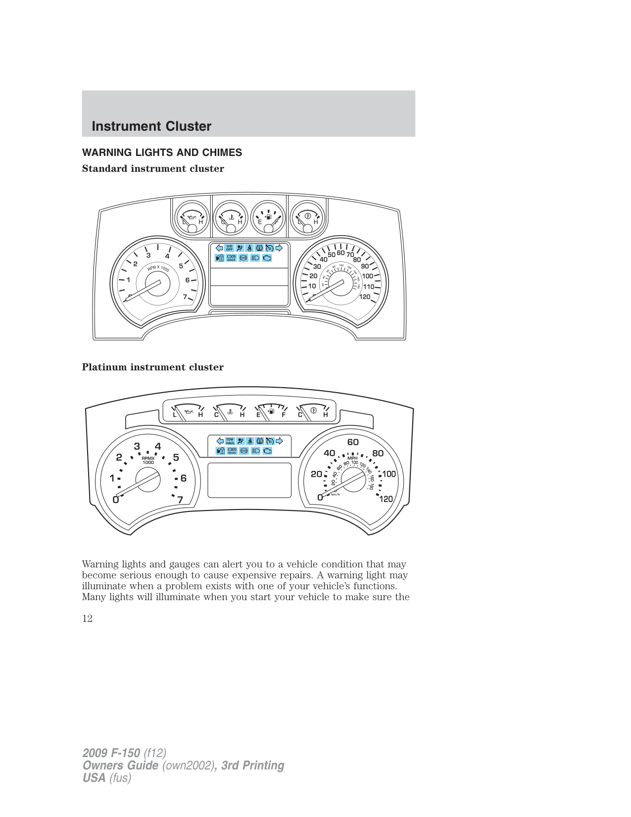
WARNING LIGHTS AND CHIMES Standard instrument cluster
Platinum instrument cluster
Warning lights and gauges can alert you to a vehicle condition that may become serious enough to cause expensive repairs. A warning light may illuminate when a problem exists with one of your vehicle’s functions. Many lights will illuminate when you start your vehicle to make sure the
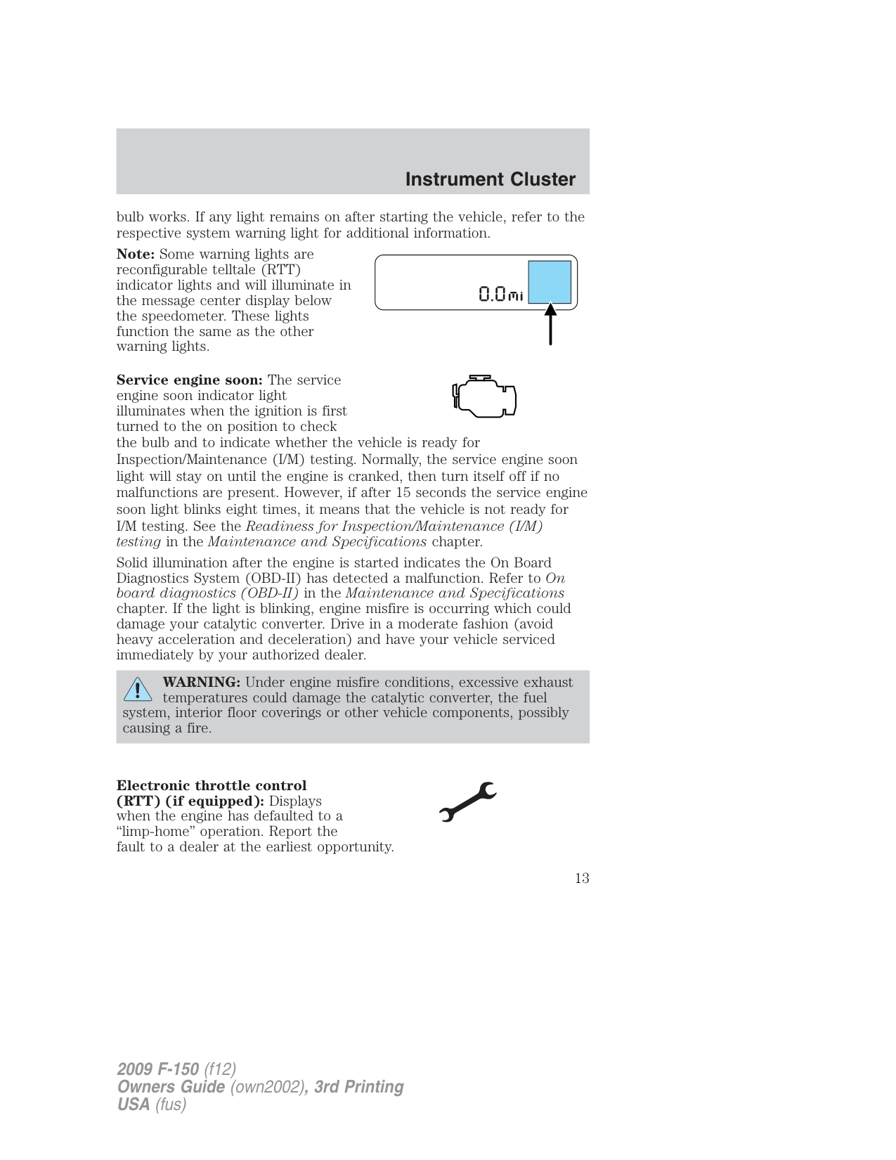
bulb works. If any light remains on after starting the vehicle, refer to the respective system warning light for additional information. Note: Some warning lights are reconfigurable telltale (RTT) indicator lights and will illuminate in the message center display below the speedometer. These lights function the same as the other warning lights.
Service engine soon: The service engine soon indicator light illuminates when the ignition is first turned to the on position to check the bulb and to indicate whether the vehicle is ready for Inspection/Maintenance (I/M) testing. Normally, the service engine soon light will stay on until the engine is cranked, then turn itself off if no malfunctions are present. However, if after 15 seconds the service engine soon light blinks eight times, it means that the vehicle is not ready for I/M testing. See the Readiness for Inspection/Maintenance (I/M) testing in the Maintenance and Specifications chapter.
Solid illumination after the engine is started indicates the On Board Diagnostics System (OBD-II) has detected a malfunction. Refer to On board diagnostics (OBD-II) in the Maintenance and Specifications chapter. If the light is blinking, engine misfire is occurring which could damage your catalytic converter. Drive in a moderate fashion (avoid heavy acceleration and deceleration) and have your vehicle serviced immediately by your authorized dealer.
WARNING: Under engine misfire conditions, excessive exhaust temperatures could damage the catalytic converter, the fuel
system, interior floor coverings or other vehicle components, possibly causing a fire.
Electronic throttle control (RTT) (if equipped): Displays when the engine has defaulted to a “limp-home” operation. Report the fault to a dealer at the earliest opportunity.
On vehicles equipped with a message center, “ENGINE FAILSAFE MODE” will be displayed, refer to Message center in the Driver Controls chapter.
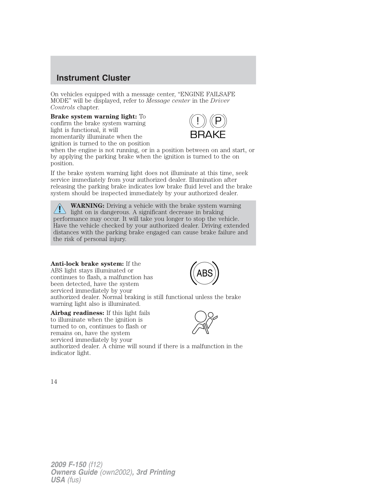
Brake system warning light: To confirm the brake system warning light is functional, it will momentarily illuminate when the ignition is turned to the on position when the engine is not running, or in a position between on and start, or by applying the parking brake when the ignition is turned to the on position.
P! BRAKE
If the brake system warning light does not illuminate at this time, seek service immediately from your authorized dealer. Illumination after releasing the parking brake indicates low brake fluid level and the brake system should be inspected immediately by your authorized dealer.
WARNING: Driving a vehicle with the brake system warning light on is dangerous. A significant decrease in braking performance may occur. It will take you longer to stop the vehicle. Have the vehicle checked by your authorized dealer. Driving extended distances with the parking brake engaged can cause brake failure and the risk of personal injury.
Anti-lock brake system: If the ABS light stays illuminated or continues to flash, a malfunction has been detected, have the system serviced immediately by your authorized dealer. Normal braking is still functional unless the brake warning light also is illuminated.
ABS
Airbag readiness: If this light fails to illuminate when the ignition is turned to on, continues to flash or remains on, have the system serviced immediately by your authorized dealer. A chime will sound if there is a malfunction in the indicator light.
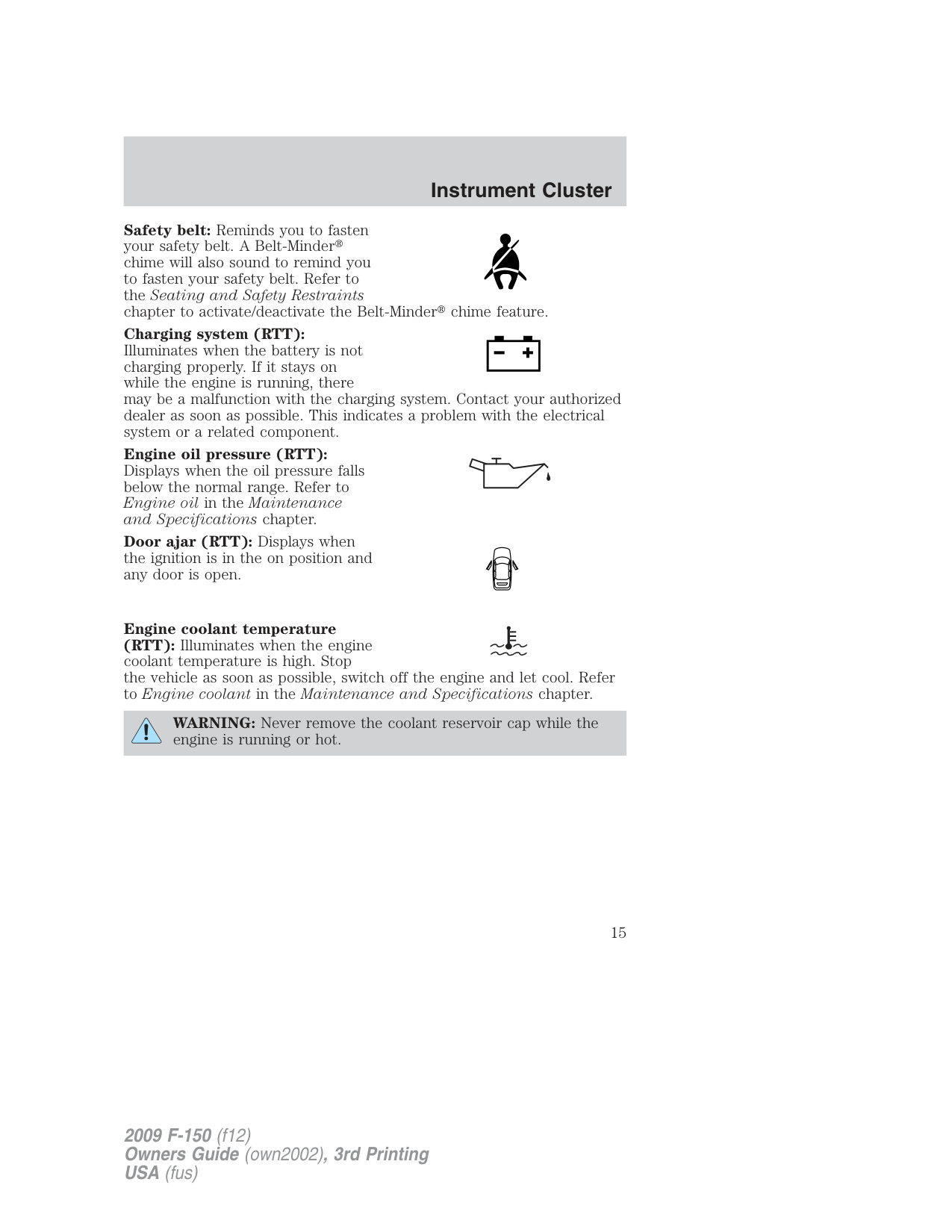
Safety belt: Reminds you to fasten your safety belt. A Belt-Minder chime will also sound to remind you to fasten your safety belt. Refer to the Seating and Safety Restraints chapter to activate/deactivate the Belt-Minder chime feature.
Charging system (RTT): Illuminates when the battery is not charging properly. If it stays on while the engine is running, there may be a malfunction with the charging system. Contact your authorized dealer as soon as possible. This indicates a problem with the electrical system or a related component.
Engine oil pressure (RTT): Displays when the oil pressure falls below the normal range. Refer to Engine oil in the Maintenance and Specifications chapter.
Door ajar (RTT): Displays when the ignition is in the on position and any door is open.
Engine coolant temperature (RTT): Illuminates when the engine coolant temperature is high. Stop the vehicle as soon as possible, switch off the engine and let cool. Refer to Engine coolant in the Maintenance and Specifications chapter.
WARNING: Never remove the coolant reservoir cap while the engine is running or hot.
Low tire pressure warning: Illuminates when your tire pressure is low. If the light remains on at start up or while driving, the tire pressure should be checked. Refer to Inflating your tires in the Tires, Wheels and Loading chapter. When the ignition is first turned to on, the light will illuminate for three seconds to ensure the bulb is working. If the light does not turn on, have the system inspected by your authorized dealer. For more information on this system, refer to Tire pressure monitoring system (TPMS) in the Tires, Wheels and Loading chapter.
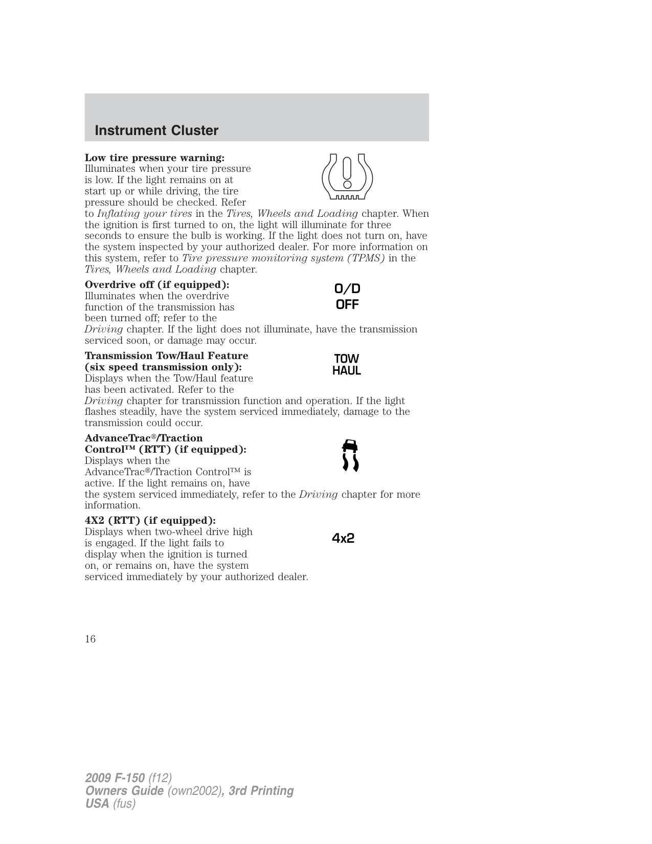
Overdrive off (if equipped): Illuminates when the overdrive function of the transmission has been turned off; refer to the Driving chapter. If the light does not illuminate, have the transmission serviced soon, or damage may occur.
O/D OFF
Transmission Tow/Haul Feature (six speed transmission only): Displays when the Tow/Haul feature has been activated. Refer to the Driving chapter for transmission function and operation. If the light flashes steadily, have the system serviced immediately, damage to the transmission could occur. AdvanceTrac /Traction Control™ (RTT) (if equipped): Displays when the AdvanceTrac /Traction Control™ is active. If the light remains on, have the system serviced immediately, refer to the Driving chapter for more information. 4X2 (RTT) (if equipped): Displays when two-wheel drive high is engaged. If the light fails to display when the ignition is turned on, or remains on, have the system serviced immediately by your authorized dealer.
4x2
Four wheel drive low (RTT) (if equipped): Displays when four-wheel drive low is engaged. If the light fails to display when the ignition is turned on, or remains on, have the system serviced immediately by your authorized dealer.
4x4 LOW
Four wheel drive high (RTT) (if equipped): Displays when four-wheel drive high is engaged. If the light fails to display when the ignition is turned on, or remains on, have the system serviced immediately by your authorized dealer.
4x4 HIGH
Electronic locking differential (RTT) (if equipped): Displays when using the electronic locking differential.
Speed control: Illuminates when the speed control is activated. Turns off when the speed control system is deactivated.
Anti-theft system: Flashes when the SecuriLock™ Passive Anti-theft System has been activated.
Turn signal: Illuminates when the left or right turn signal or the hazard lights are turned on. If the indicators stay on or flash faster, check for a burned out bulb.
High beams: Illuminates when the high beam headlamps are turned on.
Key-in-ignition warning chime: Sounds when the key is left in the ignition in the off or accessory position and the driver’s door is opened.
Headlamps on warning chime: Sounds when the headlamps or parking lamps are on, the ignition is off (the key is not in the ignition) and the driver’s door is opened.
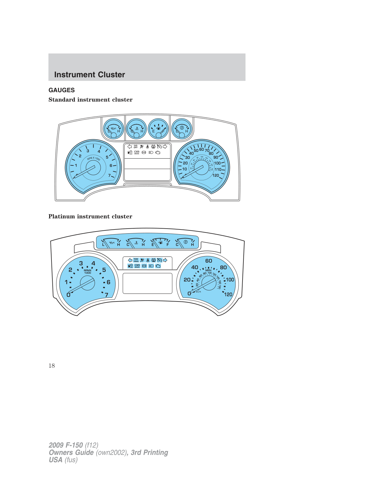
GAUGES Standard instrument cluster
Platinum instrument cluster
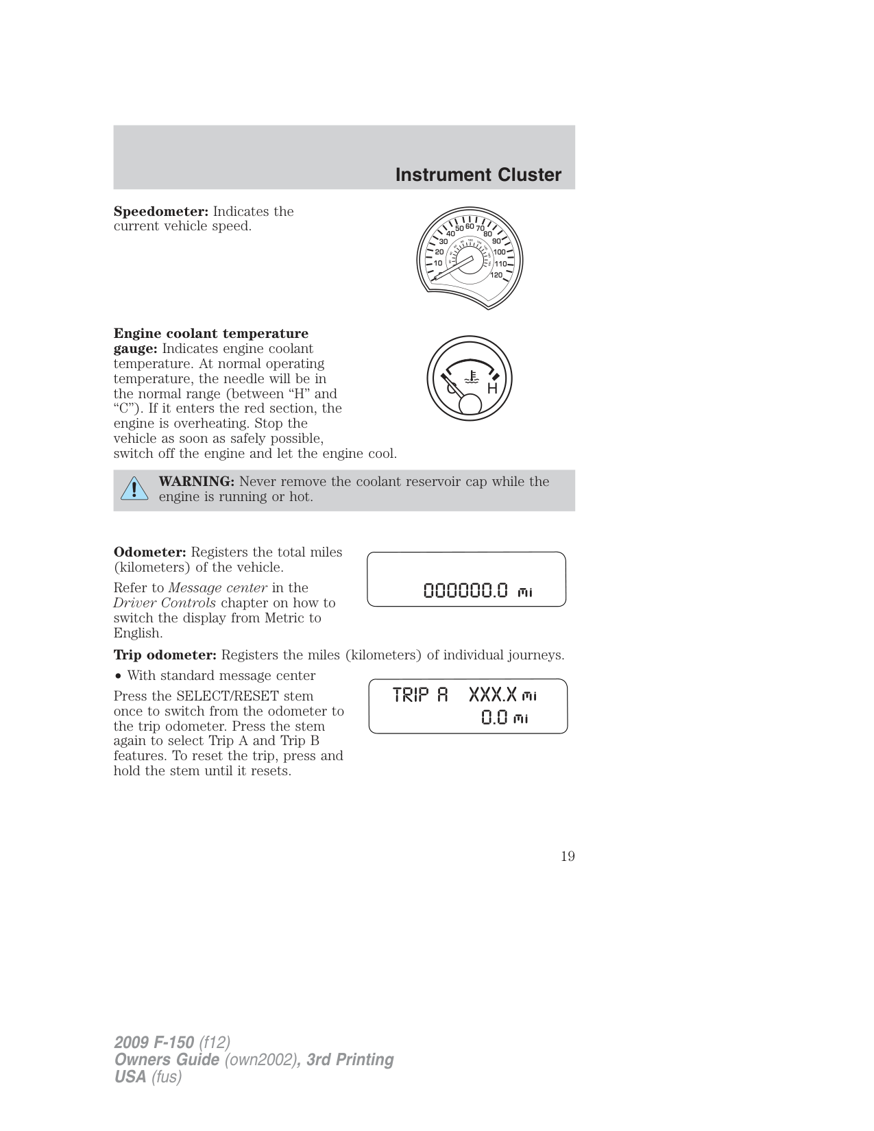
Speedometer: Indicates the current vehicle speed.
Engine coolant temperature gauge: Indicates engine coolant temperature. At normal operating temperature, the needle will be in the normal range (between “H” and “C”). If it enters the red section, the engine is overheating. Stop the vehicle as soon as safely possible, switch off the engine and let the engine cool.
WARNING: Never remove the coolant reservoir cap while the engine is running or hot.
Odometer: Registers the total miles (kilometers) of the vehicle. Refer to Message center in the Driver Controls chapter on how to switch the display from Metric to English. Trip odometer: Registers the miles (kilometers) of individual journeys.
• With standard message center Press the SELECT/RESET stem once to switch from the odometer to the trip odometer. Press the stem again to select Trip A and Trip B features. To reset the trip, press and hold the stem until it resets.
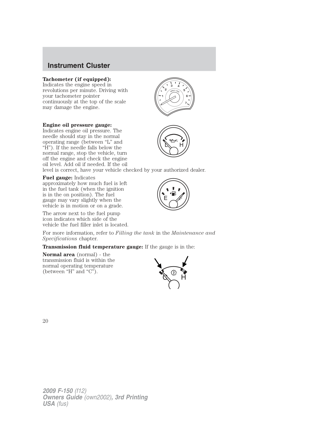
Tachometer (if equipped): Indicates the engine speed in revolutions per minute. Driving with your tachometer pointer continuously at the top of the scale may damage the engine.
Engine oil pressure gauge: Indicates engine oil pressure. The needle should stay in the normal operating range (between “L” and “H”). If the needle falls below the normal range, stop the vehicle, turn off the engine and check the engine oil level. Add oil if needed. If the oil level is correct, have your vehicle checked by your authorized dealer.
Fuel gauge: Indicates approximately how much fuel is left in the fuel tank (when the ignition is in the on position). The fuel gauge may vary slightly when the vehicle is in motion or on a grade.
The arrow next to the fuel pump icon indicates which side of the vehicle the fuel filler inlet is located.
For more information, refer to Filling the tank in the Maintenance and Specifications chapter.
Transmission fluid temperature gauge: If the gauge is in the: Normal area (normal) - the transmission fluid is within the normal operating temperature (between “H” and “C”).
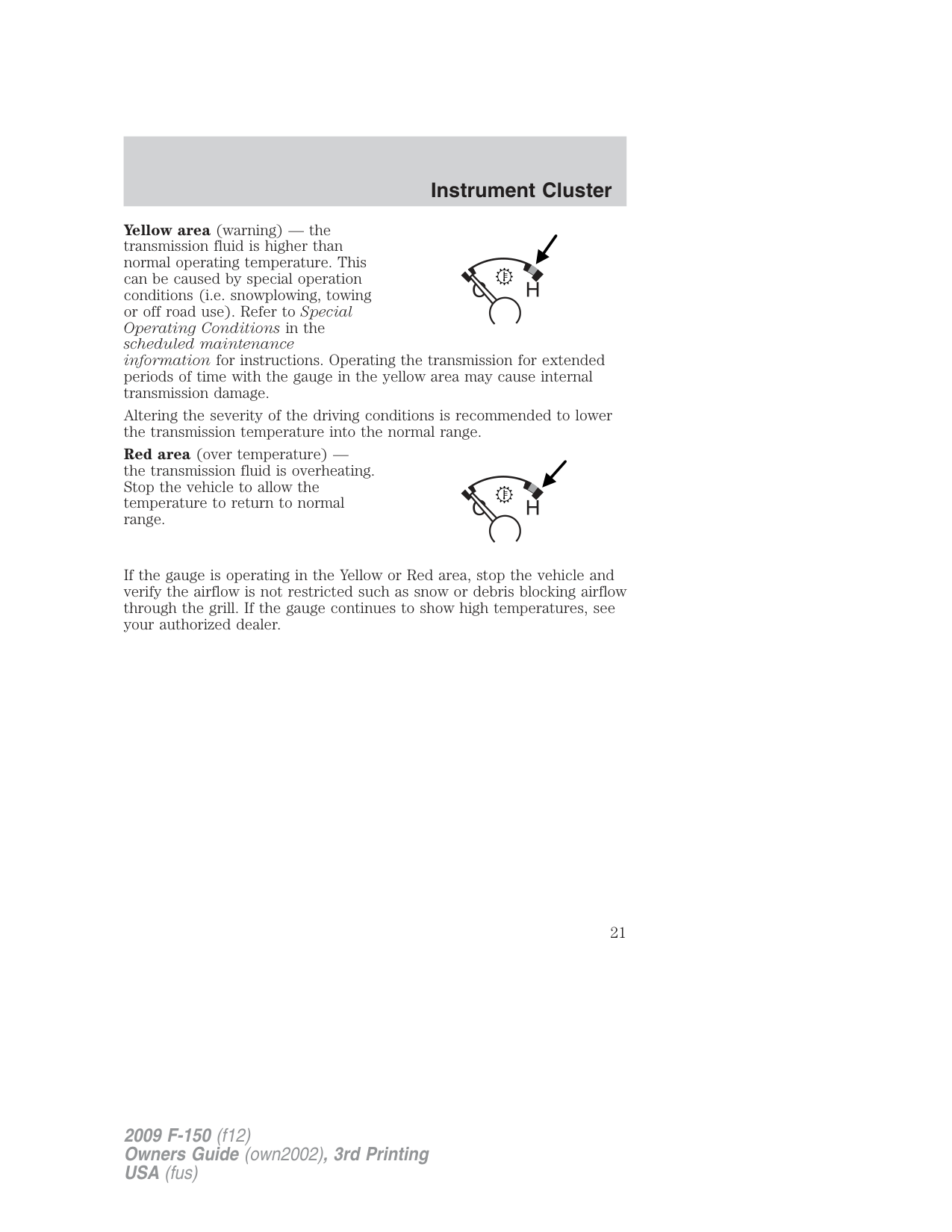
Yellow area (warning) — the transmission fluid is higher than normal operating temperature. This can be caused by special operation conditions (i.e. snowplowing, towing or off road use). Refer to Special Operating Conditions in the scheduled maintenance information for instructions. Operating the transmission for extended periods of time with the gauge in the yellow area may cause internal transmission damage.
Altering the severity of the driving conditions is recommended to lower the transmission temperature into the normal range.
Red area (over temperature) the transmission fluid is overheating. Stop the vehicle to allow the temperature to return to normal range.
If the gauge is operating in the Yellow or Red area, stop the vehicle and verify the airflow is not restricted such as snow or debris blocking airflow through the grill. If the gauge continues to show high temperatures, see your authorized dealer.
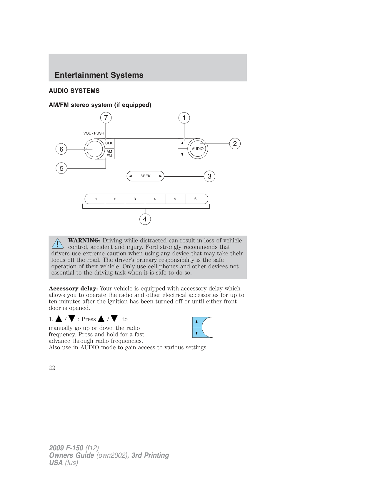
###### AUDIO SYSTEMS AM/FM stereo system (if equipped)
WARNING: Driving while distracted can result in loss of vehicle control, accident and injury. Ford strongly recommends that
drivers use extreme caution when using any device that may take their focus off the road. The driver’s primary responsibility is the safe operation of their vehicle. Only use cell phones and other devices not essential to the driving task when it is safe to do so.
Accessory delay: Your vehicle is equipped with accessory delay which allows you to operate the radio and other electrical accessories for up to ten minutes after the ignition has been turned off or until either front door is opened.
manually go up or down the radio frequency. Press and hold for a fast advance through radio frequencies. Also use in AUDIO mode to gain access to various settings.
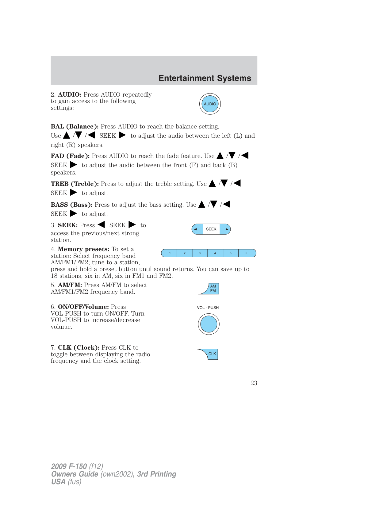
BAL (Balance): Press AUDIO to reach the balance setting. Use / / SEEK to adjust the audio between the left (L) and right (R) speakers. FAD (Fade): Press AUDIO to reach the fade feature. Use / /
SEEK to adjust the audio between the front (F) and back (B) speakers.
TREB (Treble): Press to adjust the treble setting. Use / / SEEK to adjust. BASS (Bass): Press to adjust the bass setting. Use / / SEEK to adjust.
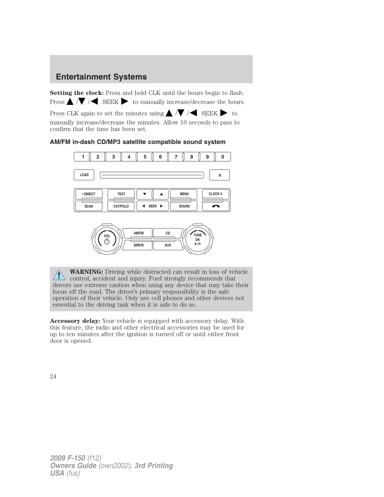
Setting the clock: Press and hold CLK until the hours begin to flash. Press / / SEEK to manually increase/decrease the hours. Press CLK again to set the minutes using / / SEEK to manually increase/decrease the minutes. Allow 10 seconds to pass to confirm that the time has been set. AM/FM in-dash CD/MP3 satellite compatible sound system
WARNING: Driving while distracted can result in loss of vehicle control, accident and injury. Ford strongly recommends that
drivers use extreme caution when using any device that may take their focus off the road. The driver’s primary responsibility is the safe operation of their vehicle. Only use cell phones and other devices not essential to the driving task when it is safe to do so.
Accessory delay: Your vehicle is equipped with accessory delay. With this feature, the radio and other electrical accessories may be used for up to ten minutes after the ignition is turned off or until either front door is opened.
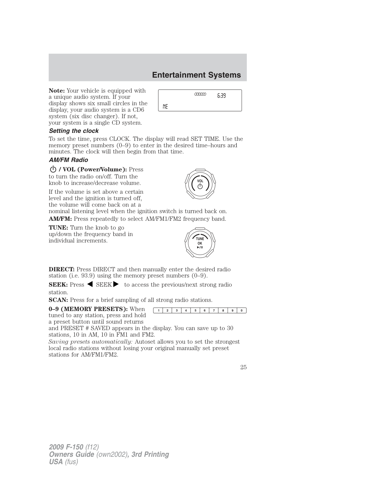
Note: Your vehicle is equipped with a unique audio system. If your display shows six small circles in the display, your audio system is a CD6 system (six disc changer). If not, your system is a single CD system.
Setting the clock To set the time, press CLOCK. The display will read SET TIME. Use the memory preset numbers (0–9) to enter in the desired time–hours and minutes. The clock will then begin from that time. AM/FM Radio
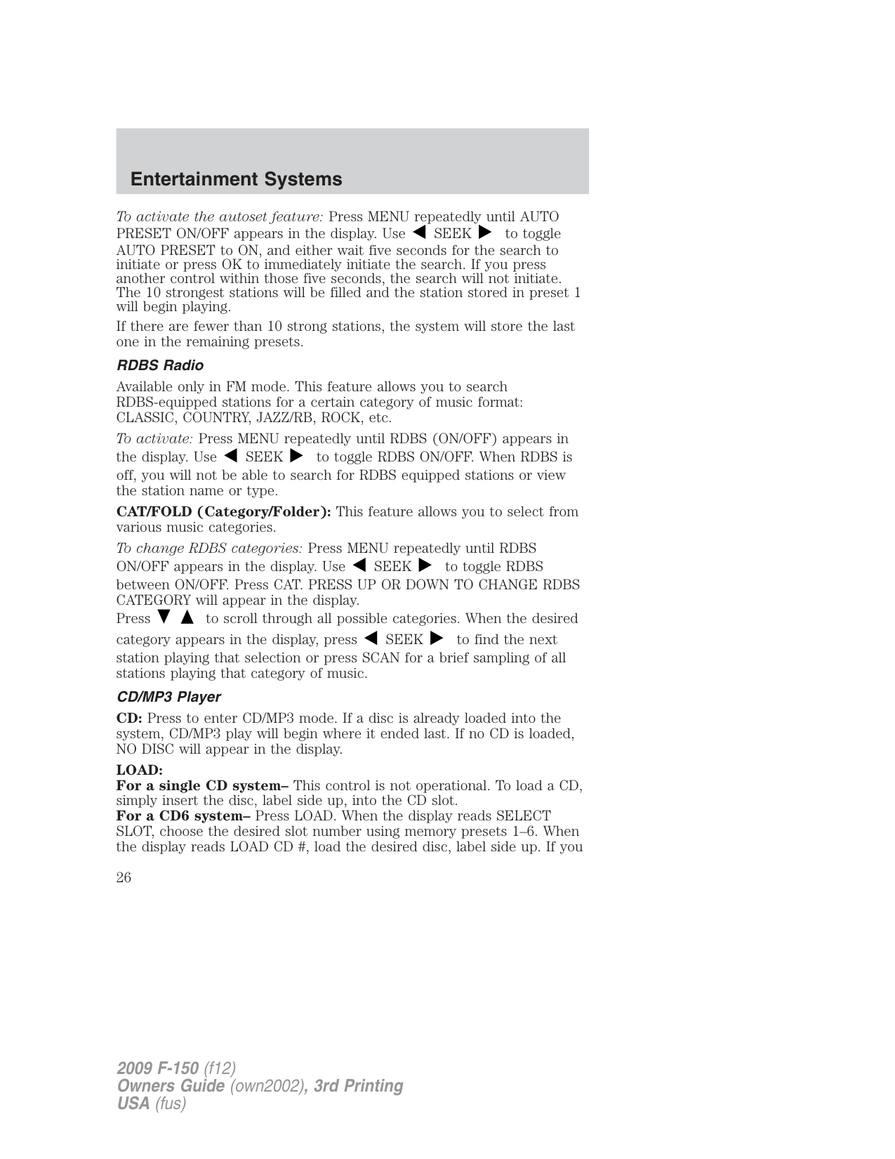
/ VOL (Power/Volume): Press to turn the radio on/off. Turn the knob to increase/decrease volume.
If the volume is set above a certain level and the ignition is turned off, the volume will come back on at a nominal listening level when the ignition switch is turned back on. AM/FM: Press repeatedly to select AM/FM1/FM2 frequency band. TUNE: Turn the knob to go up/down the frequency band in individual increments.
DIRECT: Press DIRECT and then manually enter the desired radio station (i.e. 93.9) using the memory preset numbers (0–9).
SEEK: Press SEEK to access the previous/next strong radio station. SCAN: Press for a brief sampling of all strong radio stations.
To activate the autoset feature: Press MENU repeatedly until AUTO PRESET ON/OFF appears in the display. Use SEEK to toggle AUTO PRESET to ON, and either wait five seconds for the search to initiate or press OK to immediately initiate the search. If you press another control within those five seconds, the search will not initiate. The 10 strongest stations will be filled and the station stored in preset 1 will begin playing. If there are fewer than 10 strong stations, the system will store the last one in the remaining presets. RDBS Radio
Available only in FM mode. This feature allows you to search RDBS-equipped stations for a certain category of music format: CLASSIC, COUNTRY, JAZZ/RB, ROCK, etc.
To activate: Press MENU repeatedly until RDBS (ON/OFF) appears in the display. Use SEEK to toggle RDBS ON/OFF. When RDBS is off, you will not be able to search for RDBS equipped stations or view the station name or type. CAT/FOLD (Category/Folder): This feature allows you to select from various music categories. To change RDBS categories: Press MENU repeatedly until RDBS ON/OFF appears in the display. Use SEEK to toggle RDBS between ON/OFF. Press CAT. PRESS UP OR DOWN TO CHANGE RDBS CATEGORY will appear in the display. Press to scroll through all possible categories. When the desired category appears in the display, press SEEK to find the next station playing that selection or press SCAN for a brief sampling of all stations playing that category of music. CD/MP3 Player CD: Press to enter CD/MP3 mode. If a disc is already loaded into the system, CD/MP3 play will begin where it ended last. If no CD is loaded, NO DISC will appear in the display.
LOAD: For a single CD system– This control is not operational. To load a CD, simply insert the disc, label side up, into the CD slot. For a CD6 system– Press LOAD. When the display reads SELECT SLOT, choose the desired slot number using memory presets 1–6. When the display reads LOAD CD #, load the desired disc, label side up. If you
do not choose a slot within five seconds, the system will choose for you. Once loaded, the first track will begin to play.
To auto load up to six discs– Press and hold LOAD until the display reads AUTOLOAD #. Load the desired disc, label side up. The system will prompt you to load discs for the remaining available slots. Insert the discs, one at a time, label side up, when prompted. Once loaded, the disc in preset #1 will begin to play.
Press the number preset buttons (1–6) to choose the disc you want to play.
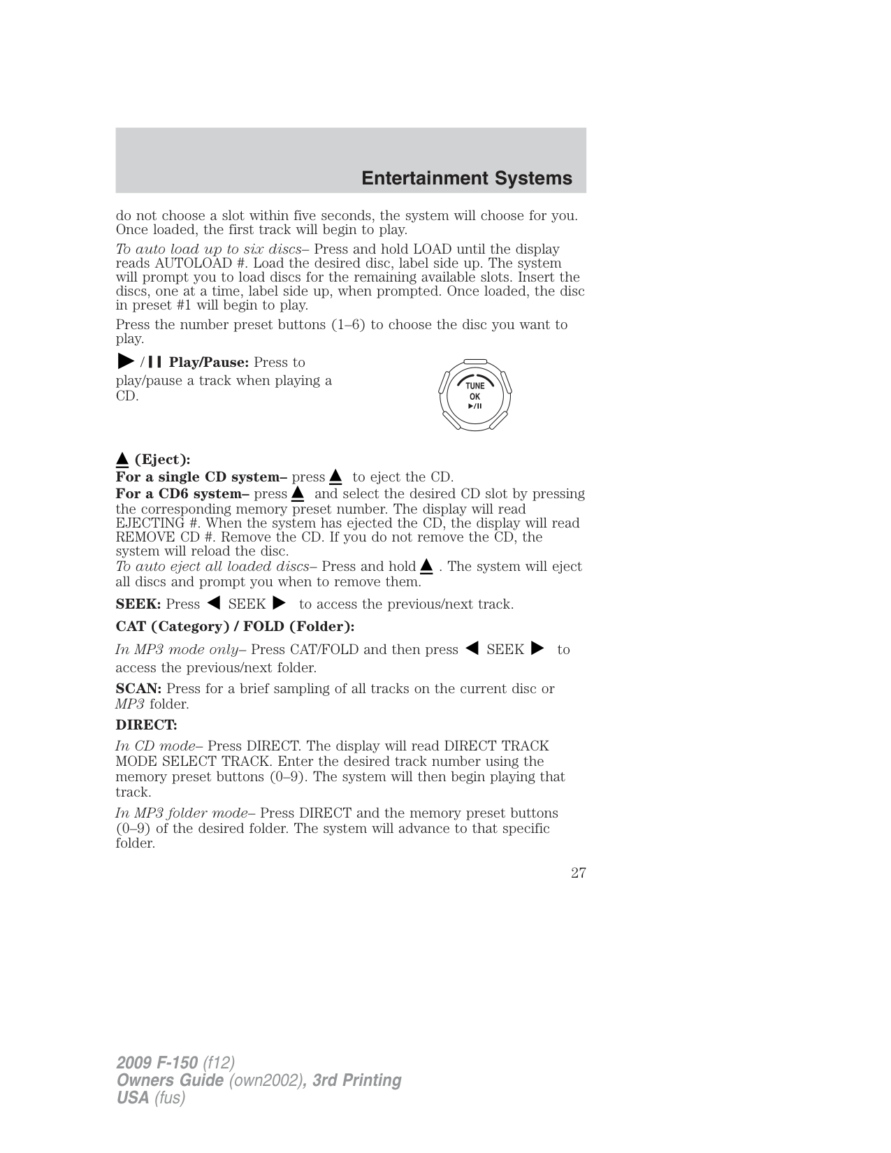
/ Play/Pause: Press to play/pause a track when playing a CD.
(Eject): For a single CD system– press to eject the CD. For a CD6 system– press and select the desired CD slot by pressing
the corresponding memory preset number. The display will read EJECTING #. When the system has ejected the CD, the display will read REMOVE CD #. Remove the CD. If you do not remove the CD, the system will reload the disc. To auto eject all loaded discs– Press and hold . The system will eject all discs and prompt you when to remove them.
SEEK: Press SEEK to access the previous/next track. CAT (Category) / FOLD (Folder): In MP3 mode only– Press CAT/FOLD and then press SEEK to access the previous/next folder. SCAN: Press for a brief sampling of all tracks on the current disc or MP3 folder. DIRECT: In CD mode– Press DIRECT. The display will read DIRECT TRACK MODE SELECT TRACK. Enter the desired track number using the memory preset buttons (0–9). The system will then begin playing that track. In MP3 folder mode– Press DIRECT and the memory preset buttons (0–9) of the desired folder. The system will advance to that specific folder.
TEXT: In MP3 mode only– Press TEXT repeatedly to view Album (AL), Folder (FL), Song (SO) and Artist (AR) in the display, if available. In TEXT MODE: Sometimes the display requires additional text to be displayed. When theindicatorisactive,press TEXT and then press SEEK to view the additional display text. COMPRESSION: Press MENU repeatedly until COMPRESSION ON/OFF appears in the display. Use SEEK to toggle between ON/OFF. When COMPRESSION is ON, the system will bring the soft and loud CD passages together for a more consistent listening level. SHUFFLE: Press MENU repeatedly until SHUFFLE ON/OFF appears in the display. Use SEEK to toggle between ON/OFF. If you wish to engage shuffle mode right away, press SEEK to begin random play. Otherwise, random play will begin when the current track is finished playing. The system will only shuffle the disc currently playing. Satellite Radio (if equipped)
Satellite radio is available only with a valid SIRIUS radio subscription. Check with your authorized dealer for availability.
SIRIUS: Press repeatedly to access satellite radio mode, if equipped. Press repeatedly to cycle through SAT1, SAT2 and SAT3 modes.
TUNE: Turn to go to the next / previous available SIRIUS satellite station.
DIRECT: Press DIRECT then enter the desired channel (i.e. 002) using the memory preset buttons (0–9). If you only enter one digit, press OK and the system will go to that satellite channel. If you enter three digits, the system will automatically go to that channel, if available. You may cancel your entry by pressing DIRECT. If an invalid station number is entered, INVALID CHANNEL will appear in the display and the system will continue playing the current station.
SEEK: Press SEEK to seek to the previous/next channel. If a specific category is selected, (Jazz, Rock, News, etc.), press SEEK to seek to the previous/next channel in the selected category. Press and hold SEEK to fast seek through the previous/next channels. SCAN: Press SCAN for a brief sampling of all available SIRIUS satellite
channels. If a specific category is selected, (Jazz, Rock, News, etc.) press SCAN for a brief sampling of all available SIRIUS satellite channels within the selected category.
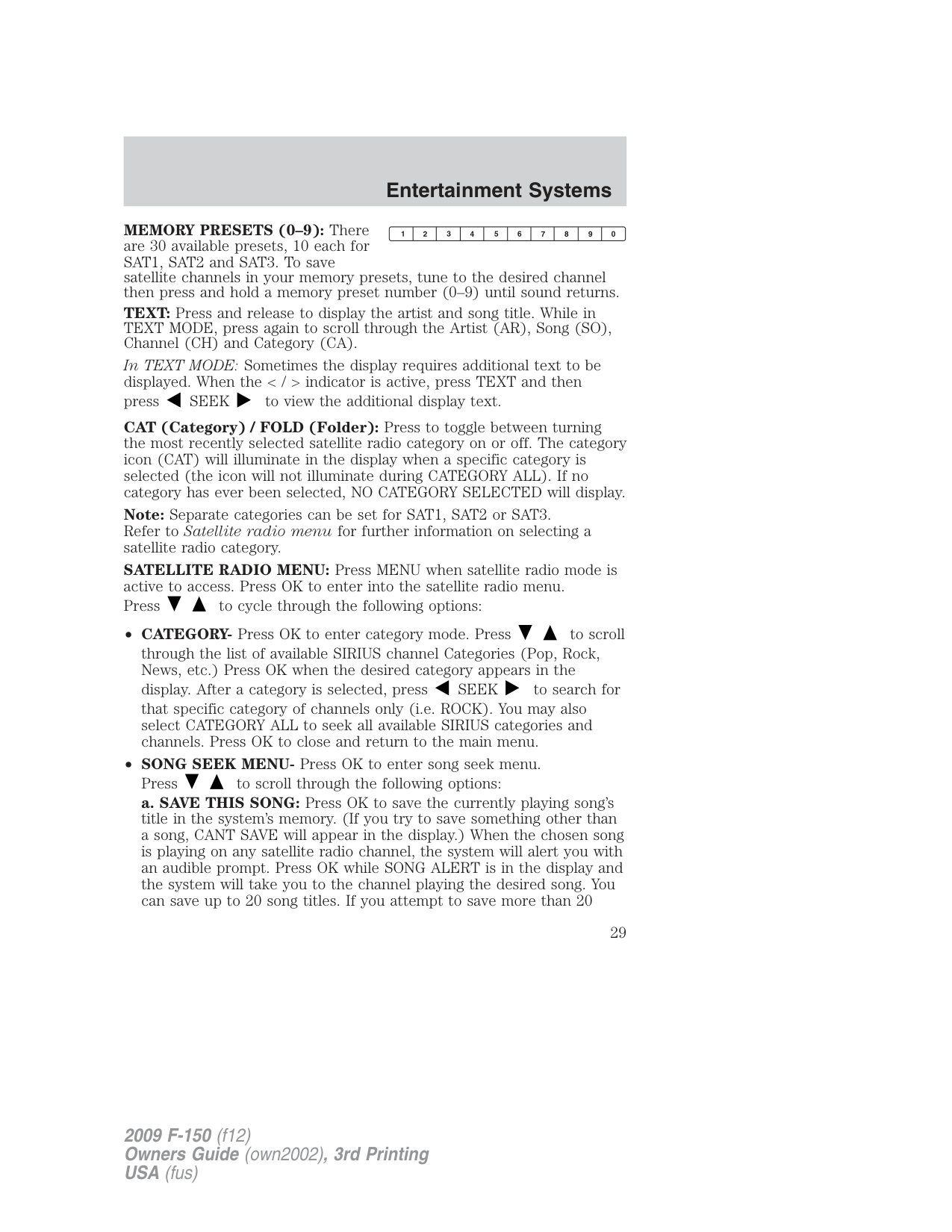
MEMORY PRESETS (0–9): There are 30 available presets, 10 each for SAT1, SAT2 and SAT3. To save satellite channels in your memory presets, tune to the desired channel then press and hold a memory preset number (0–9) until sound returns. TEXT: Press and release to display the artist and song title. While in TEXT MODE, press again to scroll through the Artist (AR), Song (SO), Channel (CH) and Category (CA). In TEXT MODE: Sometimes the display requires additional text to be displayed. When theindicatorisactive,press TEXT and then press SEEK to view the additional display text. CAT (Category) / FOLD (Folder): Press to toggle between turning the most recently selected satellite radio category on or off. The category icon (CAT) will illuminate in the display when a specific category is selected (the icon will not illuminate during CATEGORY ALL). If no category has ever been selected, NO CATEGORY SELECTED will display. Note: Separate categories can be set for SAT1, SAT2 or SAT3. Refer to Satellite radio menu for further information on selecting a satellite radio category. SATELLITE RADIO MENU: Press MENU when satellite radio mode is active to access. Press OK to enter into the satellite radio menu. Press to cycle through the following options:
Sound Adjustments Press SOUND repeatedly to cycle through the following features:
BASS: Press SEEK to adjust the level of bass. TREBLE: Press SEEK to adjust the level of treble. BALANCE: Press SEEK to adjust the audio between the left (L) and right (R) speakers. FADE: Press SEEK to adjust the audio between the back (B) and front (F) speakers. SPEED COMPENSATED VOLUME: With this feature on, radio volume automatically gets louder with increasing vehicle speed to compensate for road and wind noise. The default setting is off. Use SEEK to adjust between SPEED OFF and levels 1–7: Increasing the level from 1 (lowest setting) to 7 (highest setting) allows the radio volume to automatically change slightly with vehicle speed to compensate for road and wind noise. Recommended level is 1–3; SPEED OFF turns the feature off and level 7 is the maximum setting. Extra Features AUX: Press repeatedly to cycle through LINE IN (auxiliary audio mode), and SYNC (if equipped). For location and further information on auxiliary audio mode, refer to Auxiliary input jack later in this chapter.
If your vehicle is equipped with SYNC, please refer to supplemental information on SYNC.
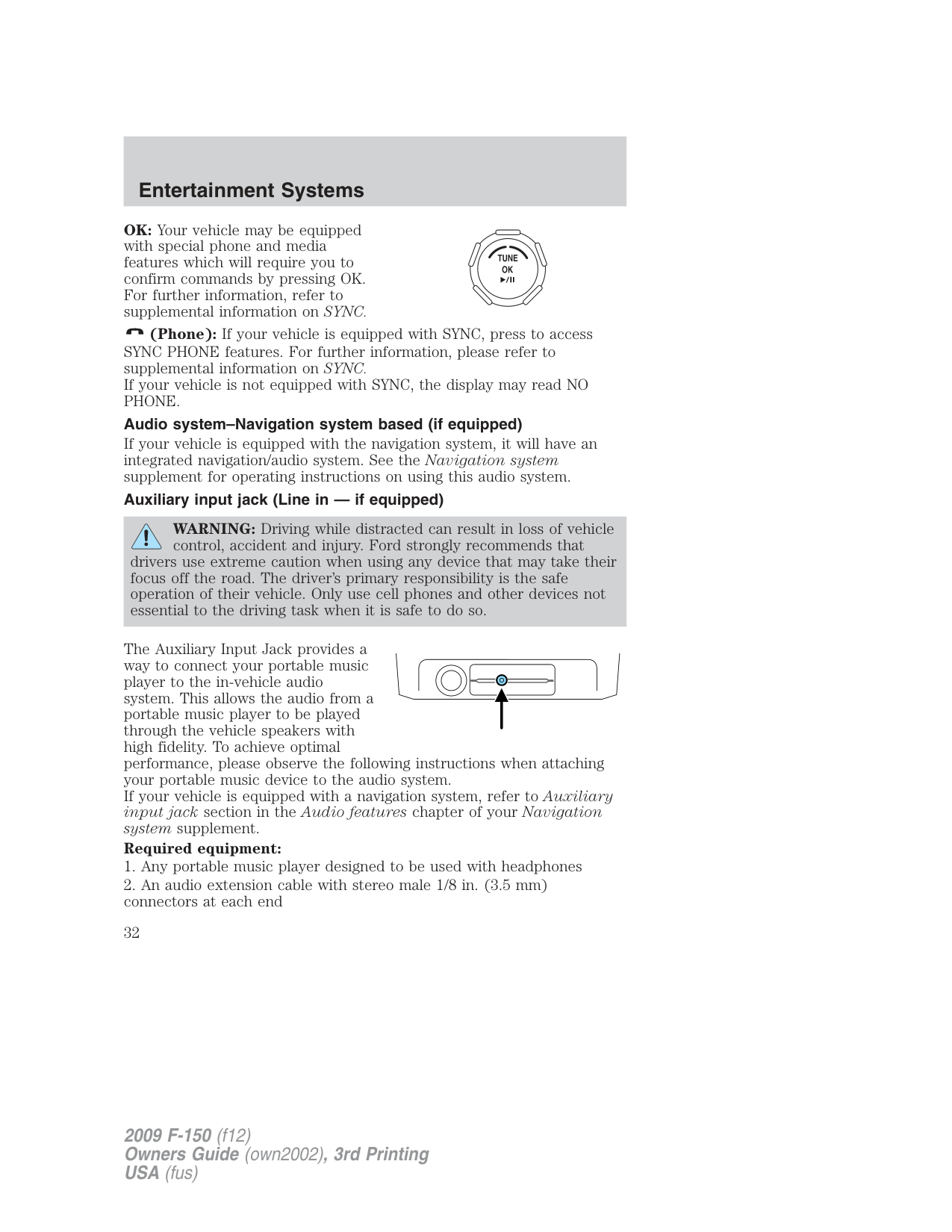
OK: Your vehicle may be equipped with special phone and media features which will require you to confirm commands by pressing OK. For further information, refer to supplemental information on SYNC.
(Phone): If your vehicle is equipped with SYNC, press to access SYNC PHONE features. For further information, please refer to supplemental information on SYNC. If your vehicle is not equipped with SYNC, the display may read NO PHONE.
Audio system–Navigation system based (if equipped) If your vehicle is equipped with the navigation system, it will have an integrated navigation/audio system. See the Navigation system supplement for operating instructions on using this audio system. Auxiliary input jack (Line in — if equipped)
WARNING: Driving while distracted can result in loss of vehicle control, accident and injury. Ford strongly recommends that
drivers use extreme caution when using any device that may take their focus off the road. The driver’s primary responsibility is the safe operation of their vehicle. Only use cell phones and other devices not essential to the driving task when it is safe to do so.
The Auxiliary Input Jack provides a way to connect your portable music player to the in-vehicle audio system. This allows the audio from a portable music player to be played through the vehicle speakers with high fidelity. To achieve optimal performance, please observe the following instructions when attaching your portable music device to the audio system. If your vehicle is equipped with a navigation system, refer to Auxiliary input jack section in the Audio features chapter of your Navigation system supplement. Required equipment:
###### To play your portable music player using the auxiliary input jack:
location, such as the center console or the glove box, when the vehicle is in motion. The audio extension cable must be long enough to allow the portable music player to be safely stored while the vehicle is in motion.
###### USB port (if equipped)
WARNING: Driving while distracted can result in loss of vehicle control, accident and injury. Ford strongly recommends that
drivers use extreme caution when using any device that may take their focus off the road. The driver’s primary responsibility is the safe operation of their vehicle. Only use cell phones and other devices not essential to the driving task when it is safe to do so.
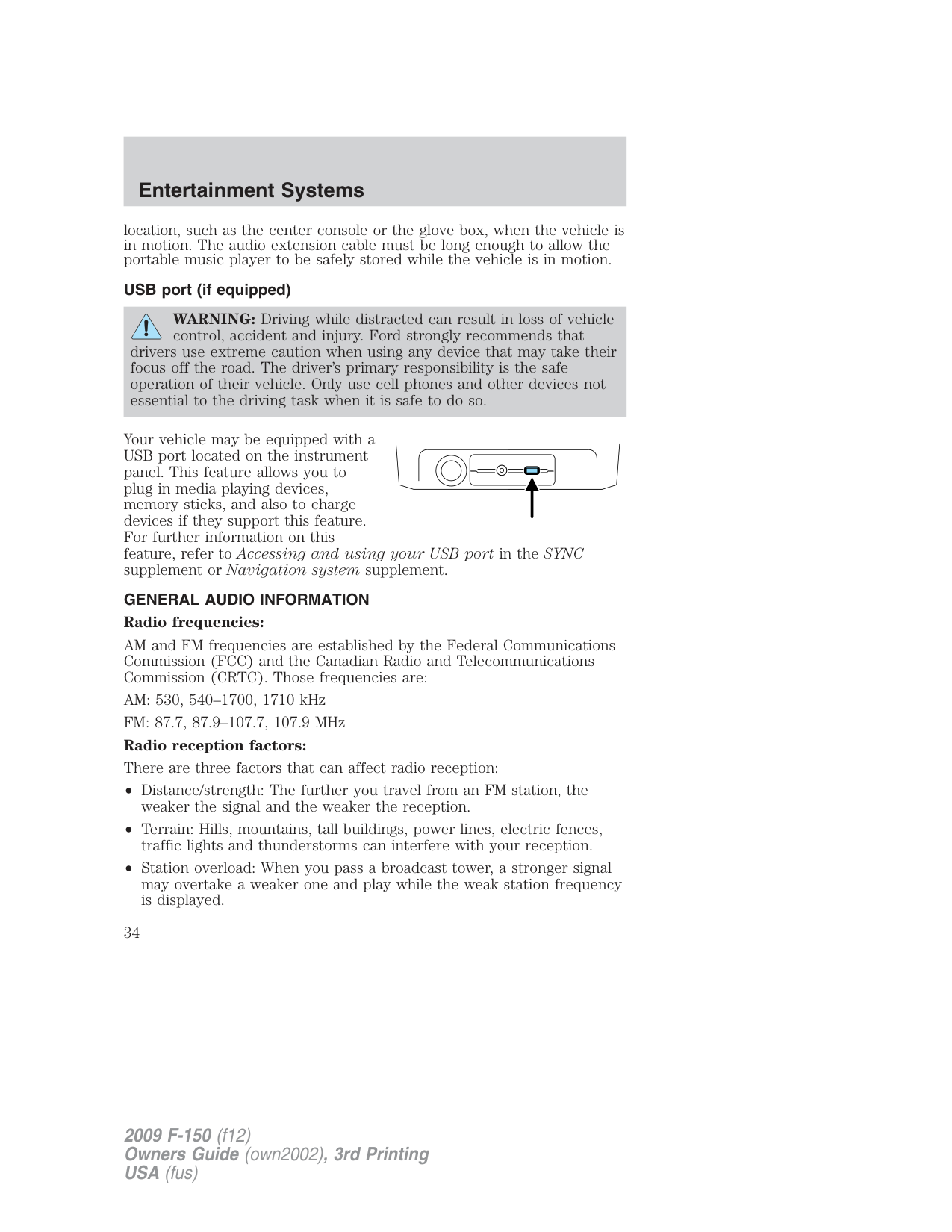
Your vehicle may be equipped with a USB port located on the instrument panel. This feature allows you to plug in media playing devices, memory sticks, and also to charge devices if they support this feature. For further information on this feature, refer to Accessing and using your USB port in the SYNC supplement or Navigation system supplement.
GENERAL AUDIO INFORMATION Radio frequencies:
AM and FM frequencies are established by the Federal Communications Commission (FCC) and the Canadian Radio and Telecommunications Commission (CRTC). Those frequencies are:
AM: 530, 540–1700, 1710 kHz FM: 87.7, 87.9–107.7, 107.9 MHz Radio reception factors: There are three factors that can affect radio reception:
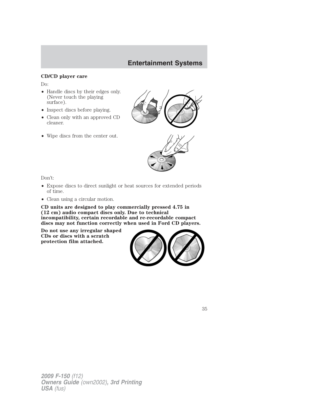
CD/CD player care Do:
Don’t:


CD units are designed to play commercially pressed 4.75 in (12 cm) audio compact discs only. Due to technical incompatibility, certain recordable and re-recordable compact discs may not function correctly when used in Ford CD players.
Do not use any irregular shaped CDs or discs with a scratch protection film attached.

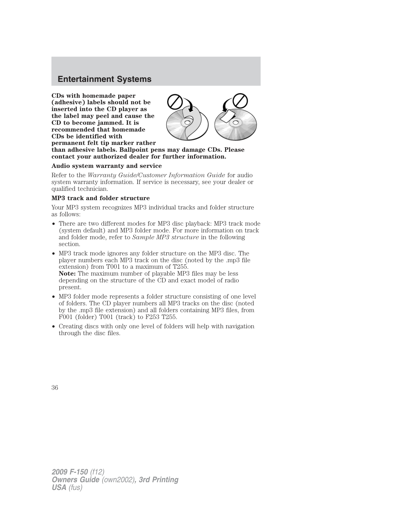
CDs with homemade paper (adhesive) labels should not be inserted into the CD player as the label may peel and cause the CD to become jammed. It is recommended that homemade CDs be identified with permanent felt tip marker rather than adhesive labels. Ballpoint pens may damage CDs. Please contact your authorized dealer for further information.

Audio system warranty and service
Refer to the Warranty Guide/Customer Information Guide for audio system warranty information. If service is necessary, see your dealer or qualified technician.
MP3 track and folder structure Your MP3 system recognizes MP3 individual tracks and folder structure

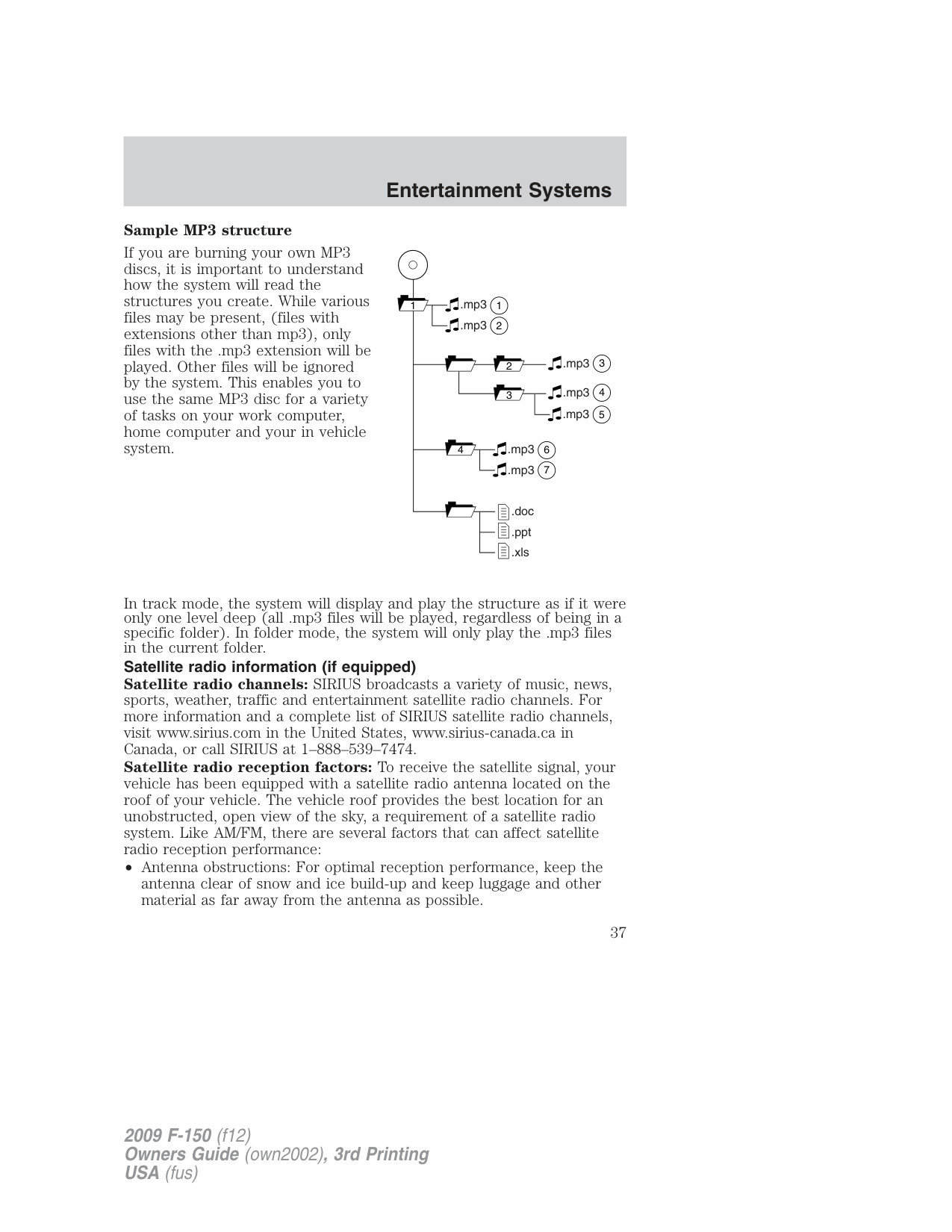
###### Sample MP3 structure
If you are burning your own MP3 discs, it is important to understand how the system will read the structures you create. While various files may be present, (files with extensions other than mp3), only files with the .mp3 extension will be played. Other files will be ignored by the system. This enables you to use the same MP3 disc for a variety of tasks on your work computer, home computer and your in vehicle system.
11
.mp3 2.mp3
3.mp3
5.mp3
64.mp3 7.mp3
.doc
| | | |---|---| | | |
.ppt .xls
In track mode, the system will display and play the structure as if it were only one level deep (all .mp3 files will be played, regardless of being in a specific folder). In folder mode, the system will only play the .mp3 files in the current folder. Satellite radio information (if equipped) Satellite radio channels: SIRIUS broadcasts a variety of music, news, sports, weather, traffic and entertainment satellite radio channels. For more information and a complete list of SIRIUS satellite radio channels, visit www.sirius.com in the United States, www.sirius-canada.ca in Canada, or call SIRIUS at 1–888–539–7474. Satellite radio reception factors: To receive the satellite signal, your vehicle has been equipped with a satellite radio antenna located on the roof of your vehicle. The vehicle roof provides the best location for an unobstructed, open view of the sky, a requirement of a satellite radio system. Like AM/FM, there are several factors that can affect satellite radio reception performance:
Unlike AM/FM audible static, you will hear an audio mute when there is a satellite radio signal interference. Your radio display may display NO SIGNAL to indicate the interference.
SIRIUS satellite radio service: SIRIUS Satellite Radio is a subscription based satellite radio service that broadcasts music, sports, news and entertainment programming. A service fee is required in order to receive SIRIUS service. Vehicles that are equipped with a factory installed SIRIUS Satellite Radio system include:
For information on extended subscription terms, contact SIRIUS at
Note: SIRIUS reserves the unrestricted right to change, rearrange, add or delete programming including canceling, moving or adding particular channels, and its prices, at any time, with or without notice to you. Ford Motor Company shall not be responsible for any such programming changes.
Satellite Radio Electronic Serial Number (ESN): This 12–digit Satellite Serial Number is needed to activate, modify or track your satellite radio account. You will need this number when communicating with SIRIUS. While in Satellite Radio mode, you can view this number on the radio display by pressing AUX and Preset 1 control simultaneously.
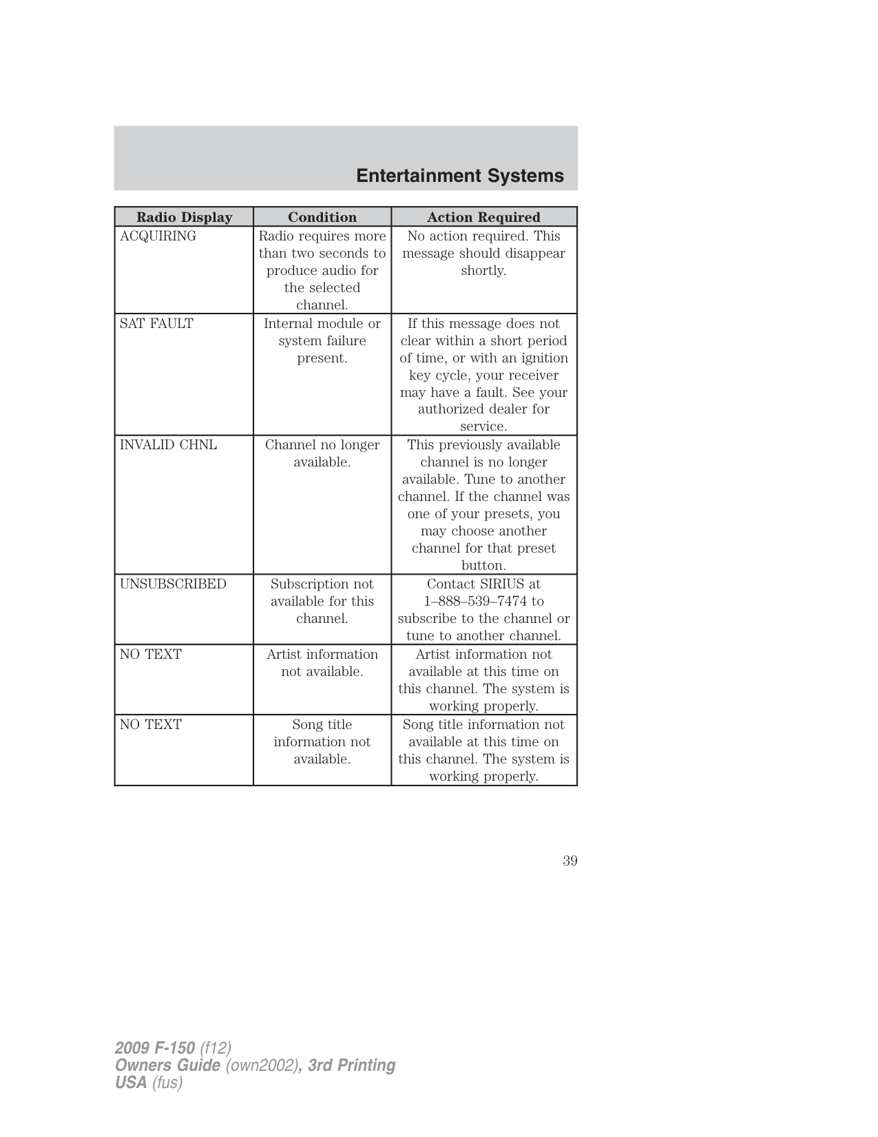
|Radio Display|Condition|Action Required| |---|---|---| |ACQUIRING|Radio requires more than two seconds to produce audio for the selected channel.|No action required. This message should disappear shortly.| |SAT FAULT|Internal module or system failure present.|If this message does not clear within a short period of time, or with an ignition key cycle, your receiver may have a fault. See your authorized dealer for service.| |INVALID CHNL|Channel no longer available.|This previously available channel is no longer available. Tune to another channel. If the channel was one of your presets, you may choose another channel for that preset button.| |UNSUBSCRIBED|Subscription not available for this channel.|Contact SIRIUS at 1–888–539–7474 to subscribe to the channel or tune to another channel.| |NO TEXT|Artist information not available.|Artist information not available at this time on this channel. The system is working properly.| |NO TEXT|Song title information not available.|Song title information not available at this time on this channel. The system is working properly.|
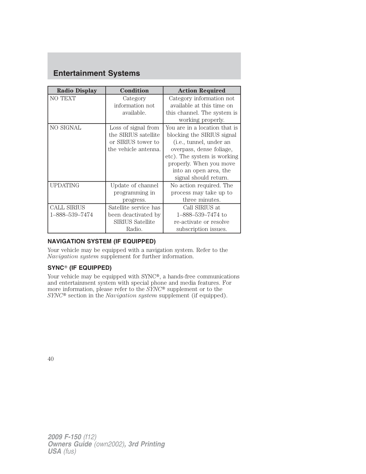
|Radio Display|Condition|Action Required| |---|---|---| |NO TEXT|Category information not available.|Category information not available at this time on this channel. The system is working properly.| |NO SIGNAL|Loss of signal from the SIRIUS satellite or SIRIUS tower to the vehicle antenna.|You are in a location that is blocking the SIRIUS signal (i.e., tunnel, under an overpass, dense foliage, etc). The system is working properly. When you move into an open area, the signal should return.| |UPDATING|Update of channel programming in progress.|No action required. The process may take up to three minutes.| |CALL SIRIUS 1–888–539–7474|Satellite service has been deactivated by SIRIUS Satellite Radio.|Call SIRIUS at 1–888–539–7474 to re-activate or resolve subscription issues.|
NAVIGATION SYSTEM (IF EQUIPPED) Your vehicle may be equipped with a navigation system. Refer to the Navigation system supplement for further information.
###### SYNC (IF EQUIPPED)
Your vehicle may be equipped with SYNC , a hands-free communications and entertainment system with special phone and media features. For more information, please refer to the SYNC supplement or to the SYNC section in the Navigation system supplement (if equipped).
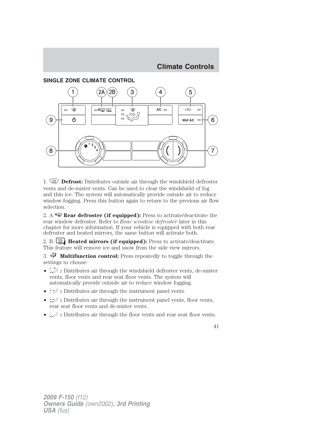
###### SINGLE ZONE CLIMATE CONTROL
| | | |---|---| | | | | | |
| | | |---|---| | | | | | |
Panel ( ) and panel/floor ( ) modes:
To increase airflow to the outer instrument panel vents, close the vents located in the middle of the instrument panel.
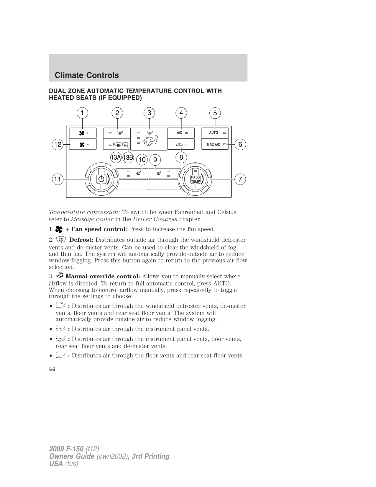
###### DUAL ZONE AUTOMATIC TEMPERATURE CONTROL WITH HEATED SEATS (IF EQUIPPED)
| | | |---|---| | | | | | |
| | | |---|---| | | | | | |
Temperature conversion: To switch between Fahrenheit and Celsius, refer to Message center in the Driver Controls chapter.
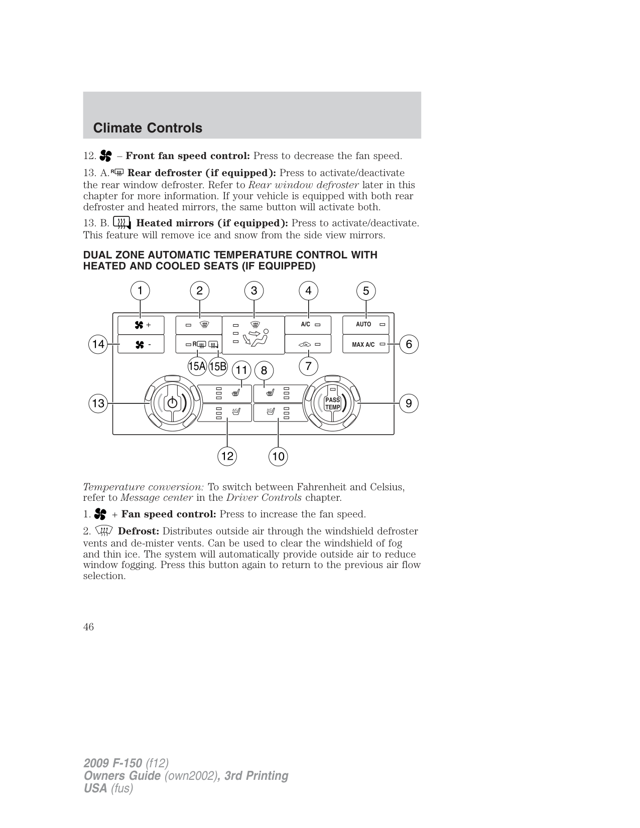
###### DUAL ZONE AUTOMATIC TEMPERATURE CONTROL WITH HEATED AND COOLED SEATS (IF EQUIPPED)
| | |
|---|---| | | | | | |
| | | |---|---| | | | | | |
| | | | |---|---|---| | | | |
Temperature conversion: To switch between Fahrenheit and Celsius, refer to Message center in the Driver Controls chapter.
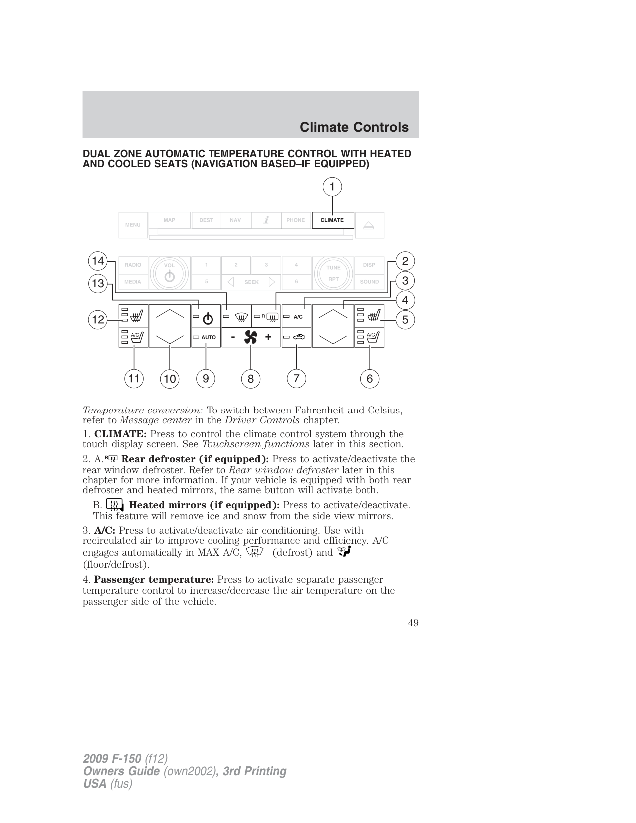
###### DUAL ZONE AUTOMATIC TEMPERATURE CONTROL WITH HEATED AND COOLED SEATS (NAVIGATION BASED–IF EQUIPPED)
| | | |---|---| | | |
| | | | |---|---|---| | | | | | | | | | | | |
Temperature conversion: To switch between Fahrenheit and Celsius, refer to Message center in the Driver Controls chapter.
B. Heated mirrors (if equipped): Press to activate/deactivate. This feature will remove ice and snow from the side view mirrors.
Recirculation may turn off automatically in all airflow selections except MAX A/C.
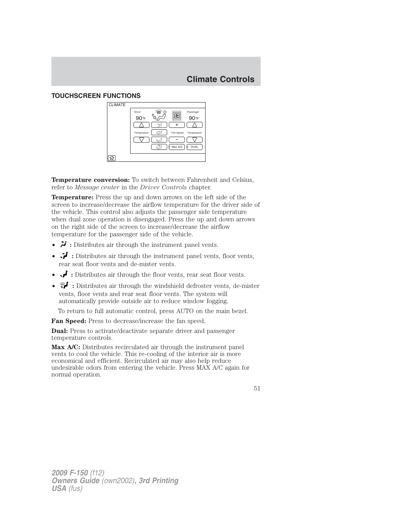
###### TOUCHSCREEN FUNCTIONS
| | |---| | |
| | |---| | |
Temperature conversion: To switch between Fahrenheit and Celsius, refer to Message center in the Driver Controls chapter.
Temperature: Press the up and down arrows on the left side of the screen to increase/decrease the airflow temperature for the driver side of the vehicle. This control also adjusts the passenger side temperature when dual zone operation is disengaged. Press the up and down arrows on the right side of the screen to increase/decrease the airflow temperature for the passenger side of the vehicle.
Fan Speed: Press to decrease/increase the fan speed. Dual: Press to activate/deactivate separate driver and passenger temperature controls. Max A/C: Distributes recirculated air through the instrument panel vents to cool the vehicle. This re-cooling of the interior air is more economical and efficient. Recirculated air may also help reduce undesirable odors from entering the vehicle. Press MAX A/C again for normal operation.
VOICE COMMANDS IN CLIMATE MODE Please refer to the Voice commands in climate mode section of the Navigation supplement for more information on using voice commands with the climate control system.
###### Operating tips
###### For maximum cooling performance MAX A/C in AUTO:
For maximum cooling performance MAX A/C in manual override control
To increase airflow to the outer instrument panel vents, close the vents located in the middle of the instrument panel.
###### REAR WINDOW DEFROSTER (IF EQUIPPED) R
The rear defroster control is located on the climate control panel and works to defrost your rear window from fog and thin ice. If equipped, it also operates the heated mirror to remove snow and thin ice from the side mirrors.
Ensure that the ignition on. Press to turn the defroster on/off. The indicator light will illuminate when activated.
Do not use razor blades or other sharp objects to clean the inside of the rear window or to remove decals from the inside of the rear window. This may cause damage to the heated grid lines and will not be covered by your warranty.
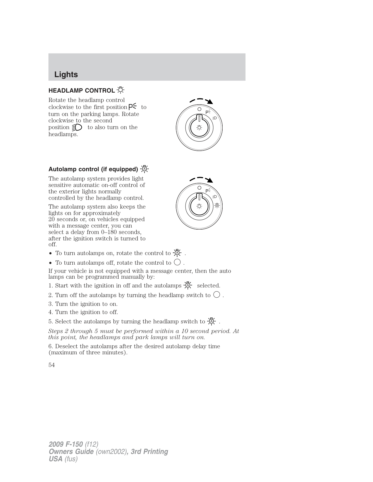
###### HEADLAMP CONTROL
Rotate the headlamp control clockwise to the first position to turn on the parking lamps. Rotate clockwise to the second position to also turn on the headlamps.
###### Autolamp control (if equipped)
The autolamp system provides light sensitive automatic on-off control of the exterior lights normally controlled by the headlamp control.
The autolamp system also keeps the lights on for approximately 20 seconds or, on vehicles equipped with a message center, you can select a delay from 0–180 seconds, after the ignition switch is turned to off.
If your vehicle is not equipped with a message center, then the auto lamps can be programmed manually by:
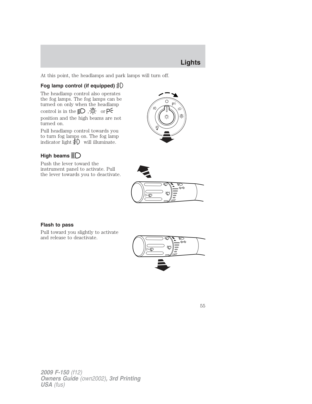
At this point, the headlamps and park lamps will turn off. Fog lamp control (if equipped)
The headlamp control also operates the fog lamps. The fog lamps can be turned on only when the headlamp control is in the , or position and the high beams are not turned on.
Pull headlamp control towards you to turn fog lamps on. The fog lamp indicator light will illuminate.
###### High beams
Push the lever toward the instrument panel to activate. Pull the lever towards you to deactivate.
######### OFF
###### Flash to pass
Pull toward you slightly to activate and release to deactivate.
Daytime running lamps (DRL) (if equipped) Turns the headlamps on with a reduced output. In order for the DRLs to function:
WARNING: Always remember to turn on your headlamps at
dusk or during inclement weather. The Daytime Running Lamp (DRL) system does not activate the tail lamps and generally may not provide adequate lighting during these conditions. Failure to activate your headlamps under these conditions may result in a collision.
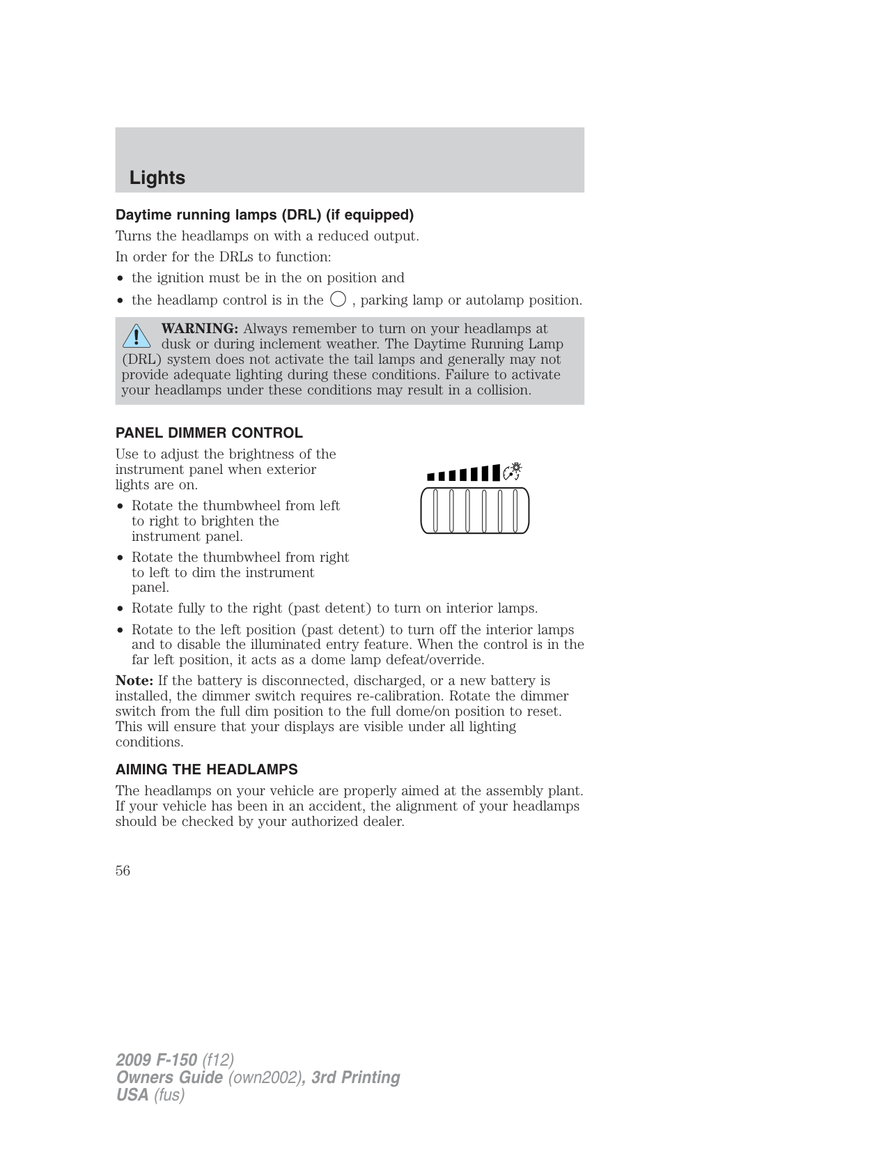
###### PANEL DIMMER CONTROL
Use to adjust the brightness of the instrument panel when exterior lights are on.
Note: If the battery is disconnected, discharged, or a new battery is installed, the dimmer switch requires re-calibration. Rotate the dimmer switch from the full dim position to the full dome/on position to reset. This will ensure that your displays are visible under all lighting conditions.
###### AIMING THE HEADLAMPS
The headlamps on your vehicle are properly aimed at the assembly plant. If your vehicle has been in an accident, the alignment of your headlamps should be checked by your authorized dealer.
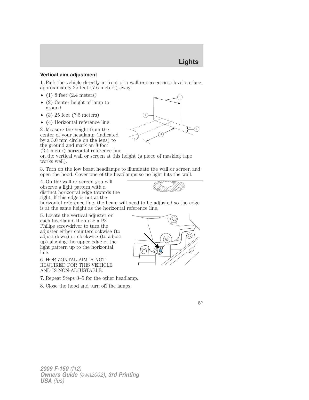
###### Vertical aim adjustment
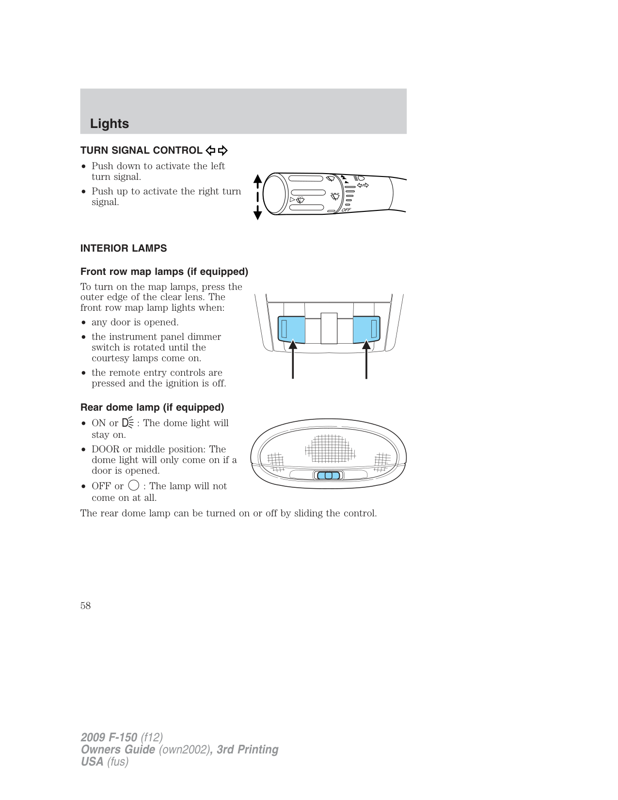
###### TURN SIGNAL CONTROL
INTERIOR LAMPS Front row map lamps (if equipped)
To turn on the map lamps, press the outer edge of the clear lens. The front row map lamp lights when:
| | | | |---|---|---| | | | |
###### Rear dome lamp (if equipped)
The rear dome lamp can be turned on or off by sliding the control.
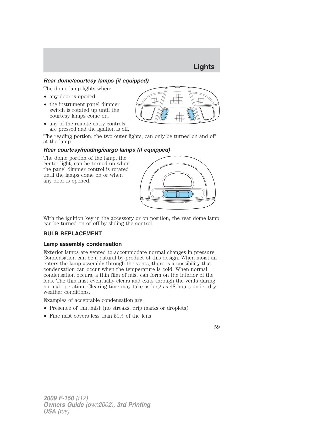
Rear dome/courtesy lamps (if equipped) The dome lamp lights when:
The reading portion, the two outer lights, can only be turned on and off
The dome portion of the lamp, the center light, can be turned on when the panel dimmer control is rotated until the lamps come on or when any door is opened.
With the ignition key in the accessory or on position, the rear dome lamp can be turned on or off by sliding the control.
BULB REPLACEMENT Lamp assembly condensation
Exterior lamps are vented to accommodate normal changes in pressure. Condensation can be a natural by-product of this design. When moist air enters the lamp assembly through the vents, there is a possibility that condensation can occur when the temperature is cold. When normal condensation occurs, a thin film of mist can form on the interior of the lens. The thin mist eventually clears and exits through the vents during normal operation. Clearing time may take as long as 48 hours under dry weather conditions.
Examples of acceptable condensation are:
Examples of unacceptable moisture (usually caused by a lamp water leak) are:
Take your vehicle to dealer for service if any of the above conditions of unacceptable moisture are present.
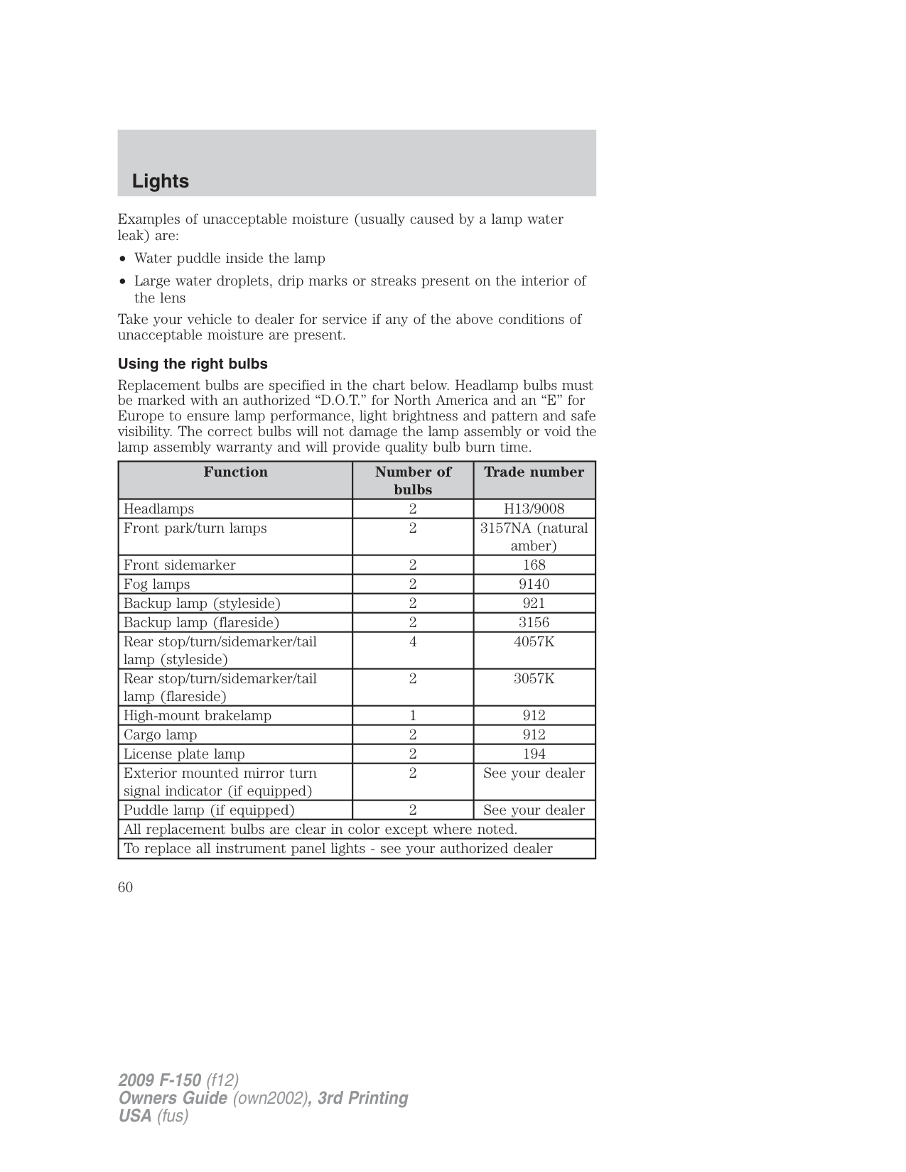
###### Using the right bulbs
Replacement bulbs are specified in the chart below. Headlamp bulbs must be marked with an authorized “D.O.T.” for North America and an “E” for Europe to ensure lamp performance, light brightness and pattern and safe visibility. The correct bulbs will not damage the lamp assembly or void the lamp assembly warranty and will provide quality bulb burn time.
|Function|Number of bulbs|Trade number| |---|---|---| |Headlamps|2|H13/9008| |Front park/turn lamps|2|3157NA (natural amber)| |Front sidemarker|2|168| |Fog lamps|2|9140| |Backup lamp (styleside)|2|921| |Backup lamp (flareside)|2|3156| |Rear stop/turn/sidemarker/tail lamp (styleside)|4|4057K| |Rear stop/turn/sidemarker/tail lamp (flareside)|2|3057K| |High-mount brakelamp|1|912| |Cargo lamp|2|912| |License plate lamp|2|194| |Exterior mounted mirror turn signal indicator (if equipped)|2|See your dealer| |Puddle lamp (if equipped)|2|See your dealer| |All replacement bulbs are clear in color except where noted.|All replacement bulbs are clear in color except where noted.|All replacement bulbs are clear in color except where noted.| |To replace all instrument panel lights - see your authorized dealer|To replace all instrument panel lights - see your authorized dealer|To replace all instrument panel lights - see your authorized dealer|
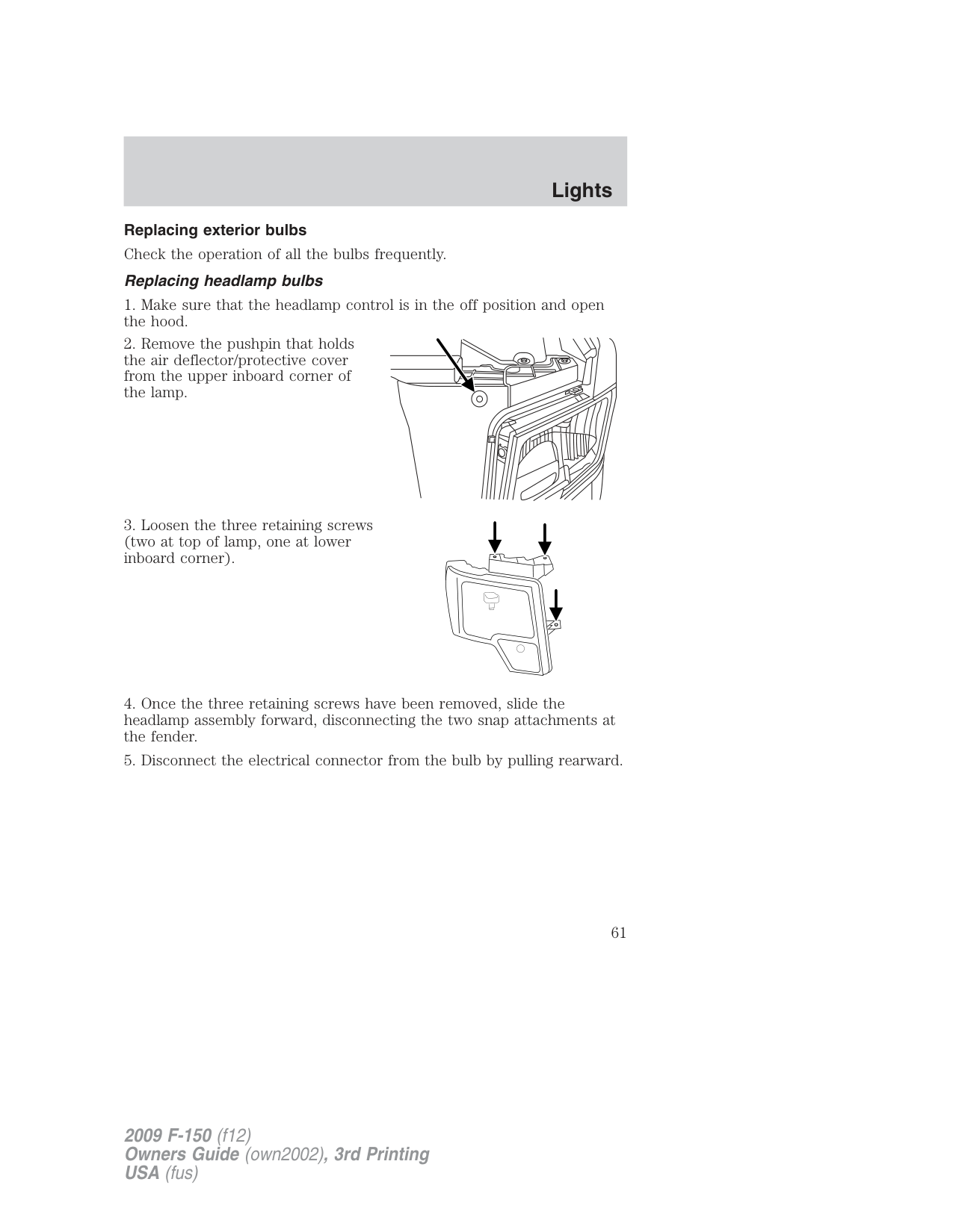
###### Replacing exterior bulbs Check the operation of all the bulbs frequently. Replacing headlamp bulbs
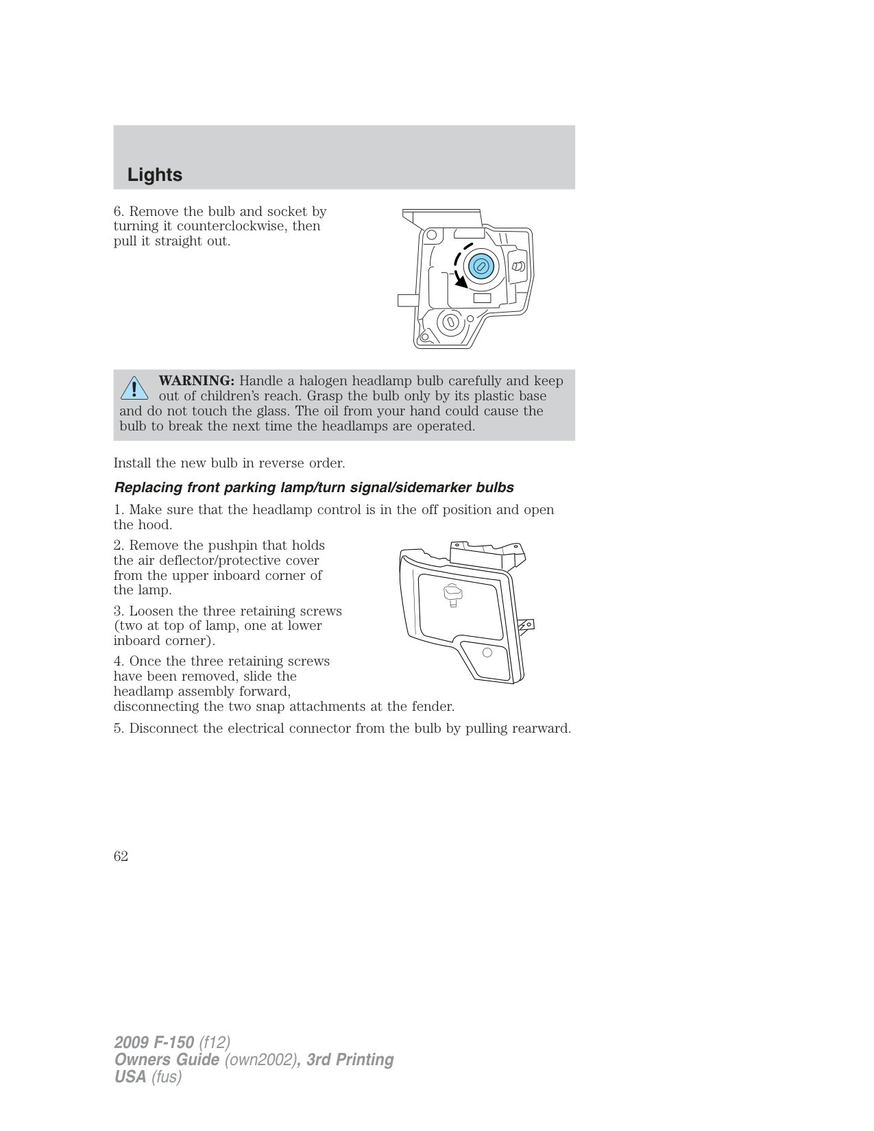
WARNING: Handle a halogen headlamp bulb carefully and keep out of children’s reach. Grasp the bulb only by its plastic base
and do not touch the glass. The oil from your hand could cause the bulb to break the next time the headlamps are operated.
Install the new bulb in reverse order. Replacing front parking lamp/turn signal/sidemarker bulbs
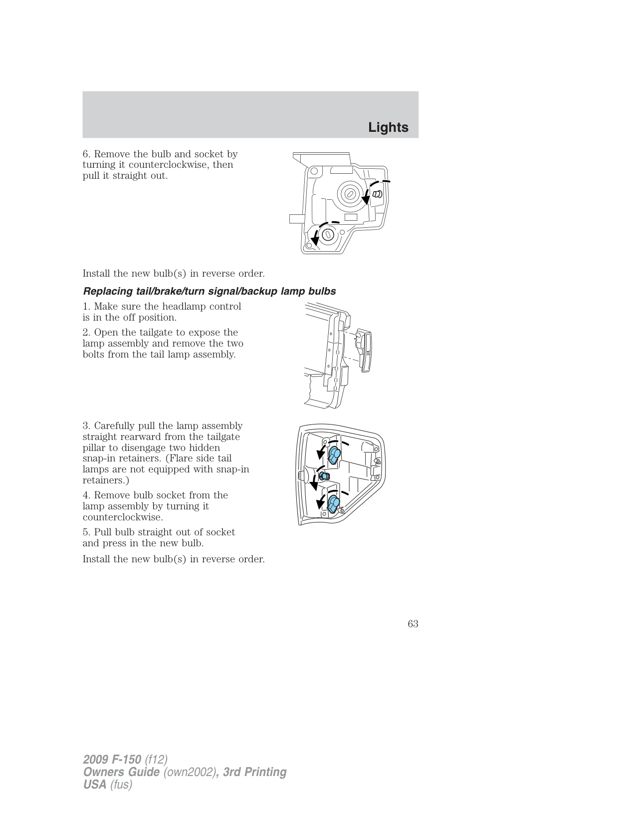
Install the new bulb(s) in reverse order. Replacing tail/brake/turn signal/backup lamp bulbs
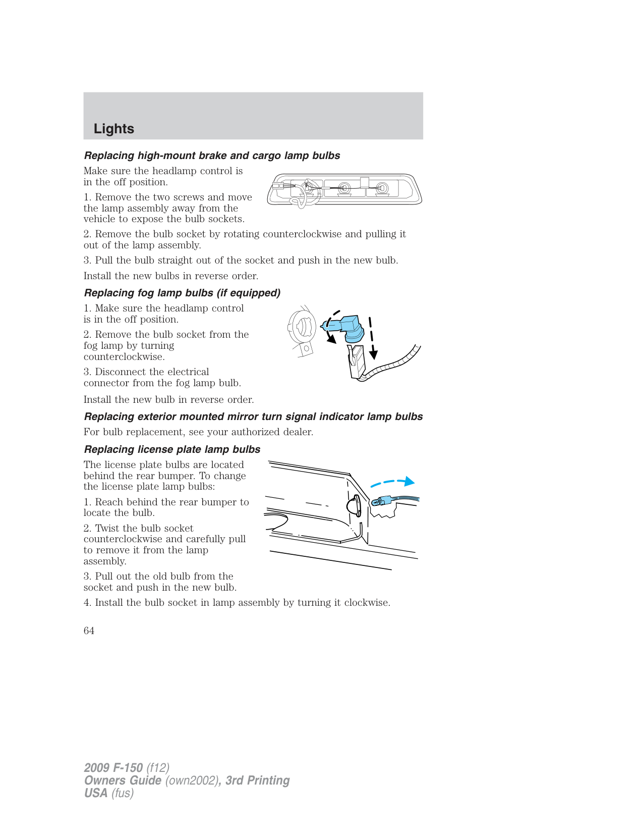
###### Replacing high-mount brake and cargo lamp bulbs
Make sure the headlamp control is in the off position.
| | |---| | |
The license plate bulbs are located behind the rear bumper. To change the license plate lamp bulbs:
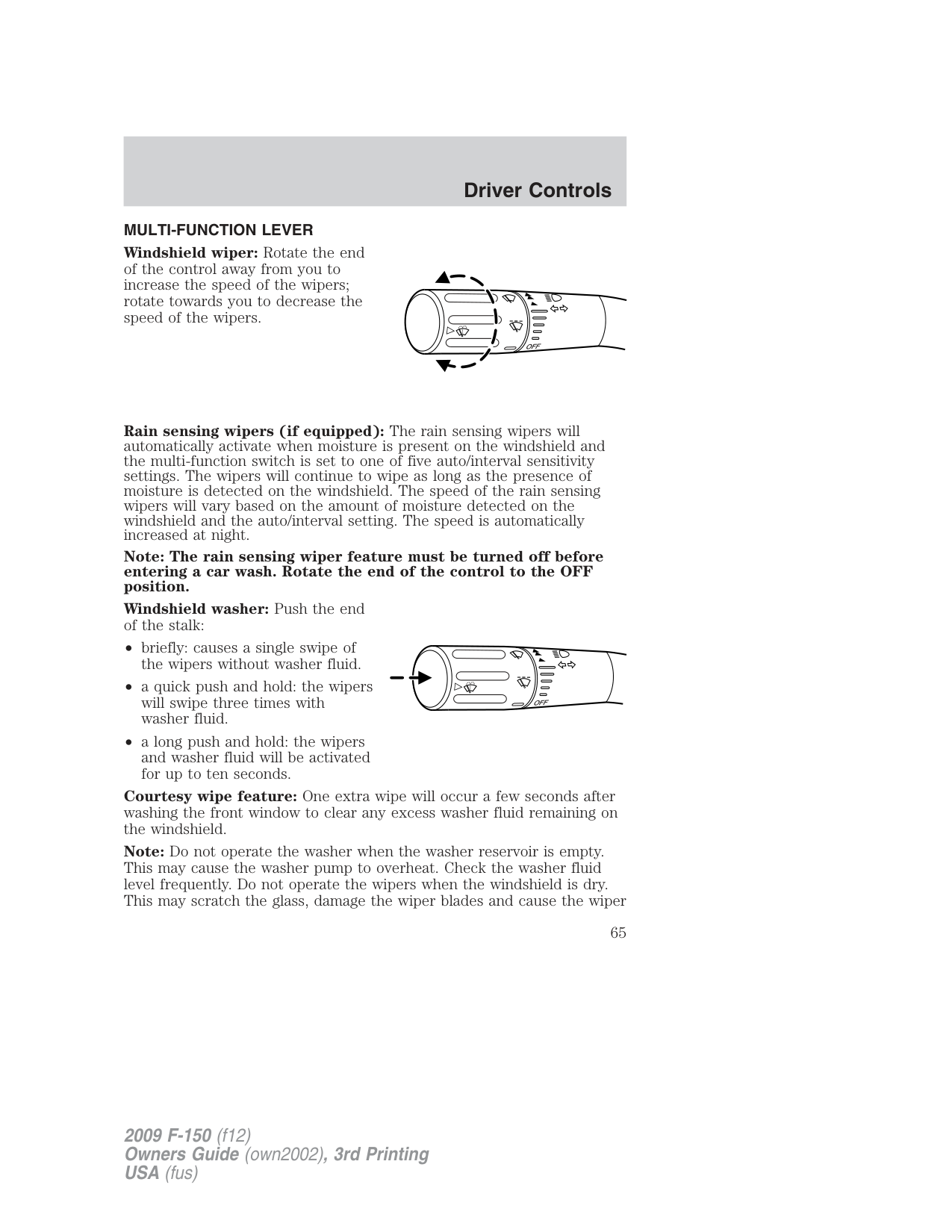
MULTI-FUNCTION LEVER Windshield wiper: Rotate the end of the control away from you to increase the speed of the wipers; rotate towards you to decrease the speed of the wipers.
Rain sensing wipers (if equipped): The rain sensing wipers will automatically activate when moisture is present on the windshield and the multi-function switch is set to one of five auto/interval sensitivity settings. The wipers will continue to wipe as long as the presence of moisture is detected on the windshield. The speed of the rain sensing wipers will vary based on the amount of moisture detected on the windshield and the auto/interval setting. The speed is automatically increased at night.
Note: The rain sensing wiper feature must be turned off before entering a car wash. Rotate the end of the control to the OFF position.
Windshield washer: Push the end of the stalk:
Courtesy wipe feature: One extra wipe will occur a few seconds after washing the front window to clear any excess washer fluid remaining on the windshield.
Note: Do not operate the washer when the washer reservoir is empty. This may cause the washer pump to overheat. Check the washer fluid level frequently. Do not operate the wipers when the windshield is dry. This may scratch the glass, damage the wiper blades and cause the wiper
motor to burn out. Before operating the wiper on a dry windshield, always use the windshield washer. In freezing weather, be sure the wiper blades are not frozen to the windshield before operating the wipers.
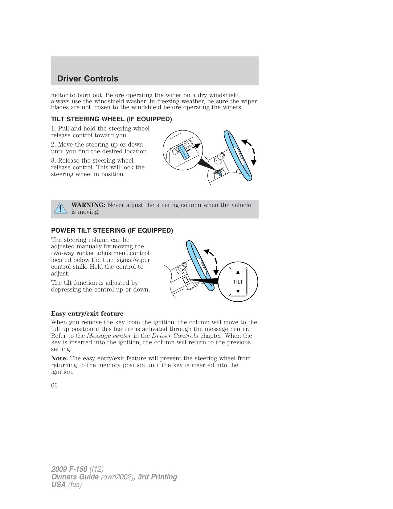
###### TILT STEERING WHEEL (IF EQUIPPED)
WARNING: Never adjust the steering column when the vehicle is moving.
###### POWER TILT STEERING (IF EQUIPPED)
The steering column can be adjusted manually by moving the two-way rocker adjustment control located below the turn signal/wiper control stalk. Hold the control to adjust.
The tilt function is adjusted by depressing the control up or down.
Easy entry/exit feature When you remove the key from the ignition, the column will move to the full up position if this feature is activated through the message center. Refer to the Message center in the Driver Controls chapter. When the key is inserted into the ignition, the column will return to the previous setting. Note: The easy entry/exit feature will prevent the steering wheel from returning to the memory position until the key is inserted into the ignition.
###### Memory feature
The steering column positions are saved when doing a memory set function and can be recalled along with the vehicle personality features when a memory position is selected through the remote entry transmitter, keyless entry keypad or memory switch on the side of the driver’s seat (if equipped with memory feature). Refer to Memory seat/power mirrors/adjustable pedals in the Seating and Safety Restraints chapter.
If the steering column adjustment control is pressed during memory recall it will cancel the automatic operation and the column will respond to manual adjustment of the control.
WARNING: Never adjust the steering column when the vehicle is moving.
On vehicles with memory feature, to prevent damage to the steering column, the steering column is designed to set a stopping position just short of the end of the column position. If the steering column encounters an object while moving up or down, a new stopping position will be set. To reset the steering column to its normal stopping position:
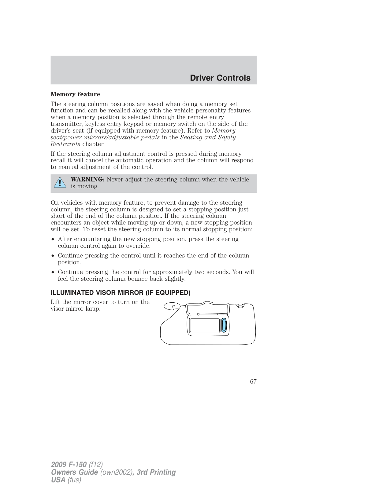
###### ILLUMINATED VISOR MIRROR (IF EQUIPPED)
Lift the mirror cover to turn on the visor mirror lamp.
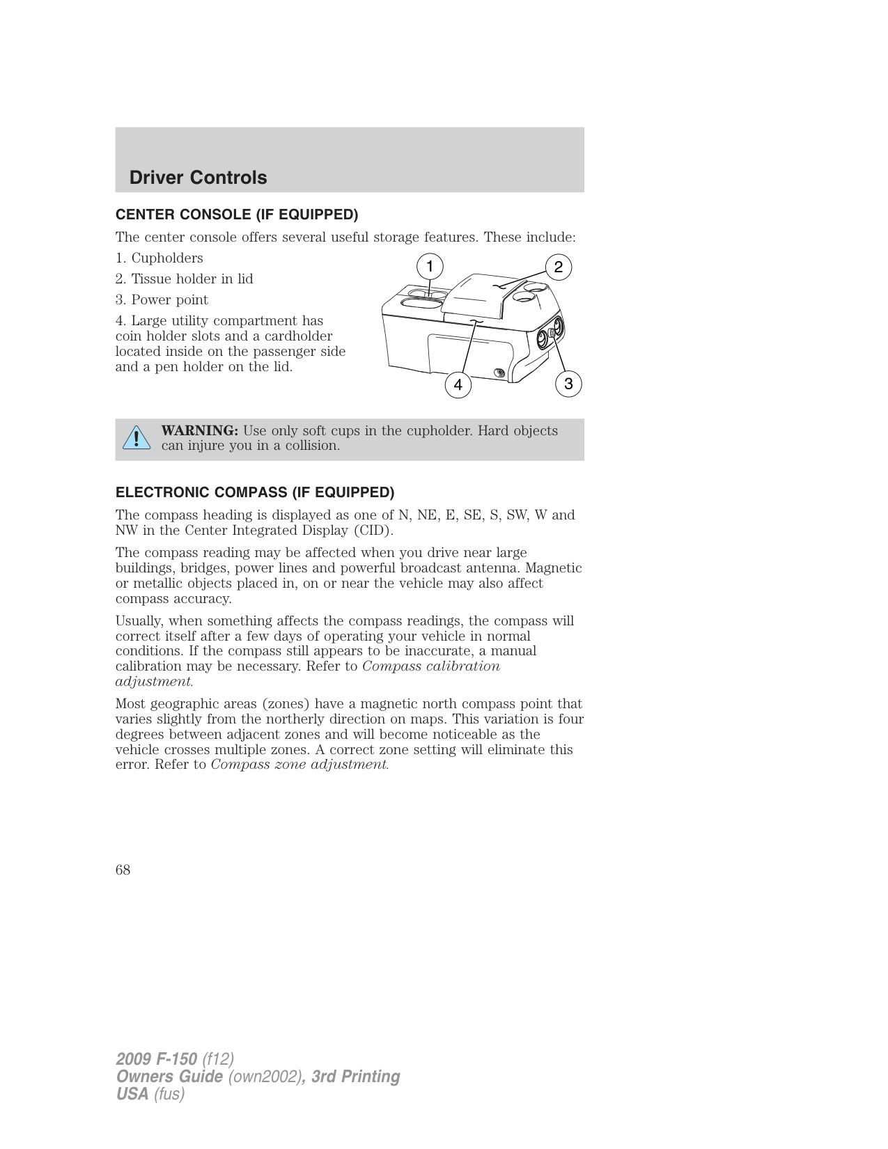
CENTER CONSOLE (IF EQUIPPED) The center console offers several useful storage features. These include:
WARNING: Use only soft cups in the cupholder. Hard objects can injure you in a collision.
###### ELECTRONIC COMPASS (IF EQUIPPED)
The compass heading is displayed as one of N, NE, E, SE, S, SW, W and NW in the Center Integrated Display (CID).
The compass reading may be affected when you drive near large buildings, bridges, power lines and powerful broadcast antenna. Magnetic or metallic objects placed in, on or near the vehicle may also affect compass accuracy.
Usually, when something affects the compass readings, the compass will correct itself after a few days of operating your vehicle in normal conditions. If the compass still appears to be inaccurate, a manual calibration may be necessary. Refer to Compass calibration adjustment.
Most geographic areas (zones) have a magnetic north compass point that varies slightly from the northerly direction on maps. This variation is four degrees between adjacent zones and will become noticeable as the vehicle crosses multiple zones. A correct zone setting will eliminate this error. Refer to Compass zone adjustment.
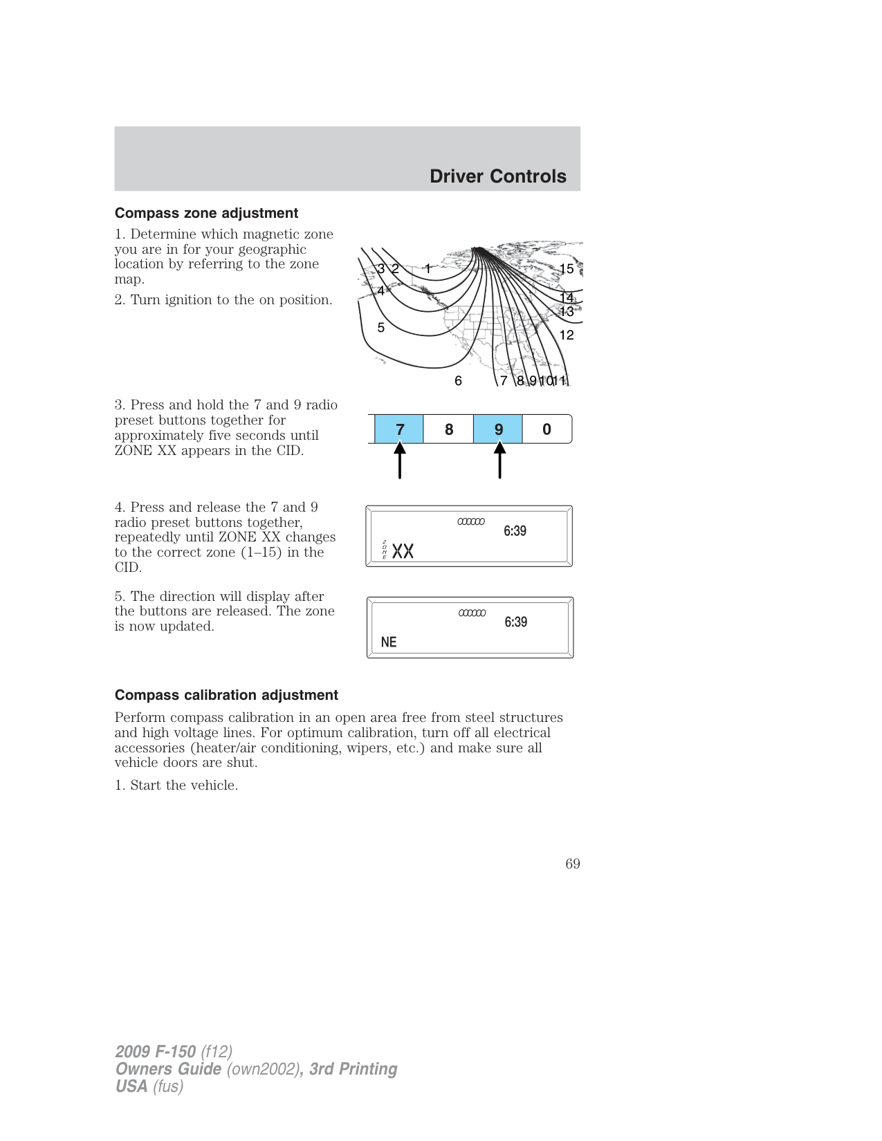
###### Compass zone adjustment

123
6 7 8 91011
###### Compass calibration adjustment
Perform compass calibration in an open area free from steel structures and high voltage lines. For optimum calibration, turn off all electrical accessories (heater/air conditioning, wipers, etc.) and make sure all vehicle doors are shut.
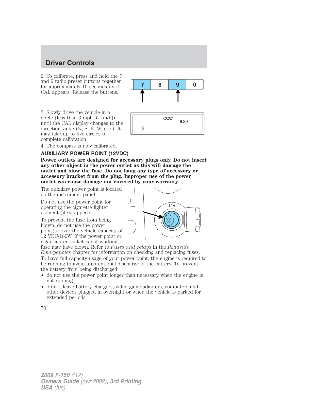
Power outlets are designed for accessory plugs only. Do not insert any other object in the power outlet as this will damage the outlet and blow the fuse. Do not hang any type of accessory or accessory bracket from the plug. Improper use of the power outlet can cause damage not covered by your warranty.
The auxiliary power point is located on the instrument panel.
Do not use the power point for operating the cigarette lighter element (if equipped).
To prevent the fuse from being blown, do not use the power point(s) over the vehicle capacity of 12 VDC/180W. If the power point or cigar lighter socket is not working, a fuse may have blown. Refer to Fuses and relays in the Roadside Emergencies chapter for information on checking and replacing fuses.
To have full capacity usage of your power point, the engine is required to be running to avoid unintentional discharge of the battery. To prevent the battery from being discharged:
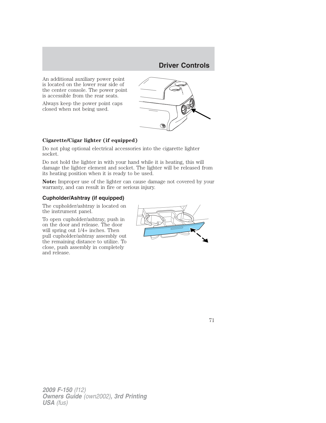
An additional auxiliary power point is located on the lower rear side of the center console. The power point is accessible from the rear seats.
Always keep the power point caps closed when not being used.
###### Cigarette/Cigar lighter (if equipped)
Do not plug optional electrical accessories into the cigarette lighter socket.
Do not hold the lighter in with your hand while it is heating, this will damage the lighter element and socket. The lighter will be released from its heating position when it is ready to be used.
Note: Improper use of the lighter can cause damage not covered by your warranty, and can result in fire or serious injury.
###### Cupholder/Ashtray (if equipped)
The cupholder/ashtray is located on the instrument panel.
To open cupholder/ashtray, push in on the door and release. The door will spring out 1/4+ inches. Then pull cupholder/ashtray assembly out the remaining distance to utilize. To close, push assembly in completely and release.
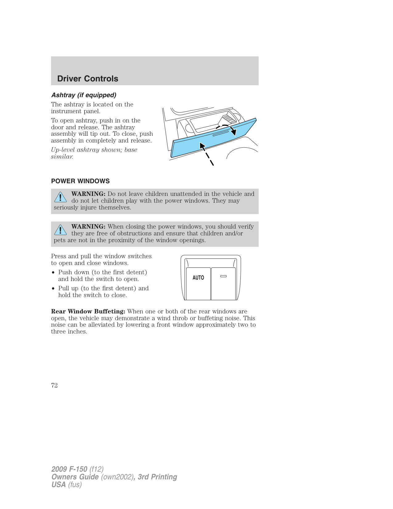
###### Ashtray (if equipped)
The ashtray is located on the instrument panel.
To open ashtray, push in on the door and release. The ashtray assembly will tip out. To close, push assembly in completely and release.
Up-level ashtray shown; base similar.
###### POWER WINDOWS
WARNING: Do not leave children unattended in the vehicle and do not let children play with the power windows. They may
seriously injure themselves.
WARNING: When closing the power windows, you should verify they are free of obstructions and ensure that children and/or
pets are not in the proximity of the window openings.
Press and pull the window switches to open and close windows.
Rear Window Buffeting: When one or both of the rear windows are
open, the vehicle may demonstrate a wind throb or buffeting noise. This noise can be alleviated by lowering a front window approximately two to three inches.
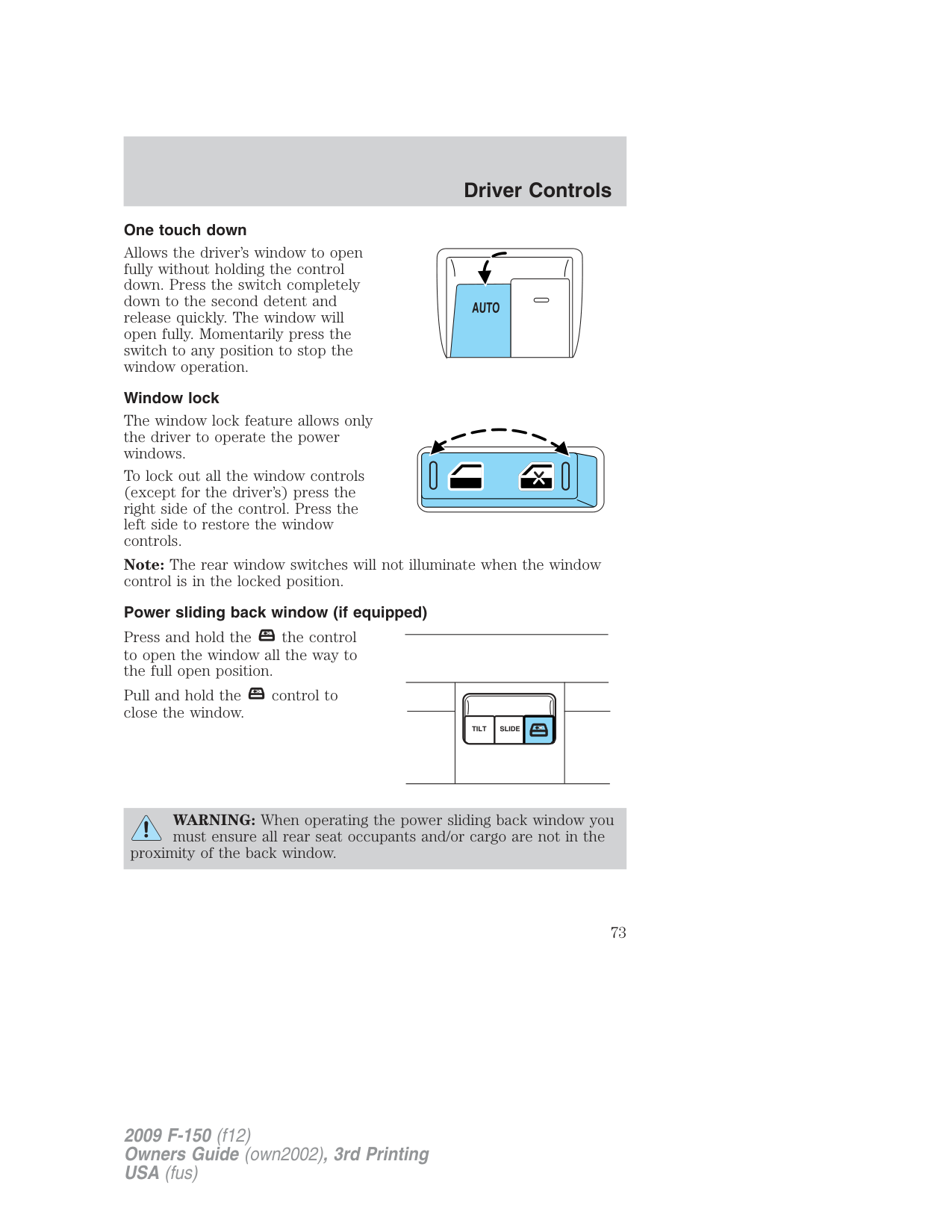
###### One touch down
Allows the driver’s window to open fully without holding the control down. Press the switch completely down to the second detent and release quickly. The window will open fully. Momentarily press the switch to any position to stop the window operation.
###### Window lock
The window lock feature allows only the driver to operate the power windows.
To lock out all the window controls (except for the driver’s) press the right side of the control. Press the left side to restore the window controls.
Note: The rear window switches will not illuminate when the window control is in the locked position.
###### Power sliding back window (if equipped)
Press and hold the the control to open the window all the way to the full open position.
| | | | |---|---|---| | | | |
Pull and hold the control to close the window.
WARNING: When operating the power sliding back window you must ensure all rear seat occupants and/or cargo are not in the
proximity of the back window.
WARNING: Do not leave children unattended in the vehicle and do not let children play with the power sliding back window.
They may seriously injure themselves.
Accessory delay (if equipped) With accessory delay, the window switches may be used for up to
###### INTERIOR MIRROR
The interior rear view mirror has two pivot points on the support arm which lets you adjust the mirror up or down and from side to side.
WARNING: Do not adjust the mirror while the vehicle is in motion.
###### Automatic dimming interior rear view mirror (if equipped)
Your vehicle may be equipped with an interior rear view mirror that has an auto-dimming function (optional on the driver’s side exterior mirror). The electronic day/night mirror will change from the normal (high reflective) state to the non-glare (darkened) state when bright lights (glare) reach the interior mirror. When the interior mirror detects bright light from behind the vehicle, the interior rear view mirror and the driver’s side exterior mirror (if equipped) will automatically adjust (darken) to minimize glare.
###### Without microphone
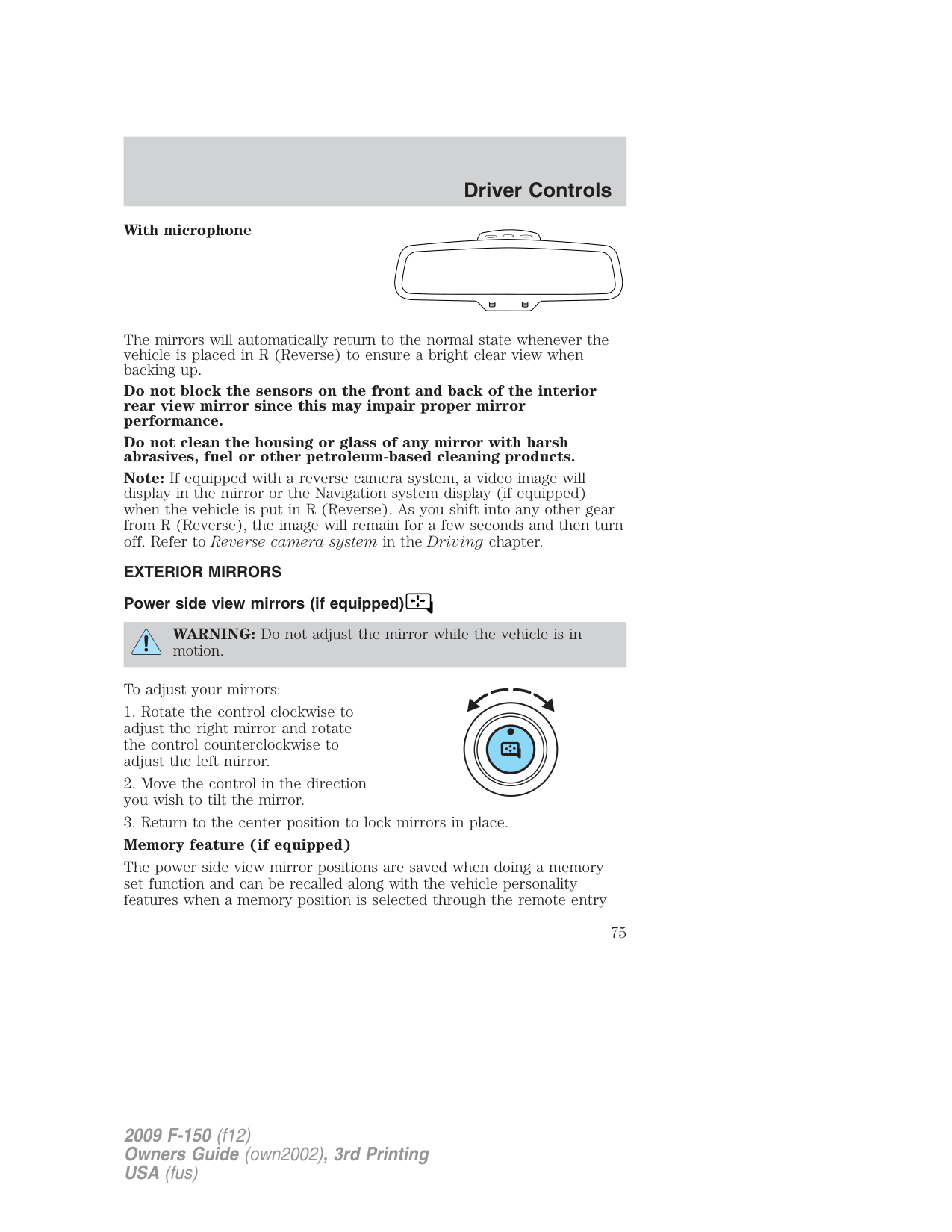
###### With microphone
The mirrors will automatically return to the normal state whenever the vehicle is placed in R (Reverse) to ensure a bright clear view when backing up.
Do not block the sensors on the front and back of the interior rear view mirror since this may impair proper mirror performance.
Do not clean the housing or glass of any mirror with harsh abrasives, fuel or other petroleum-based cleaning products.
Note: If equipped with a reverse camera system, a video image will display in the mirror or the Navigation system display (if equipped) when the vehicle is put in R (Reverse). As you shift into any other gear from R (Reverse), the image will remain for a few seconds and then turn off. Refer to Reverse camera system in the Driving chapter.
EXTERIOR MIRRORS Power side view mirrors (if equipped)
WARNING: Do not adjust the mirror while the vehicle is in motion.
To adjust your mirrors:
The power side view mirror positions are saved when doing a memory set function and can be recalled along with the vehicle personality features when a memory position is selected through the remote entry
transmitter, keyless entry keypad or memory switch on the driver’s seat. Refer to Memory seats and mirrors in the Seating and Safety Restraints chapter.
###### Automatic dimming feature (if equipped)
The driver’s side view mirror has an auto-dimming function. For more information, refer to Automatic dimming interior rear view mirror in this chapter.
###### Fold-away mirrors
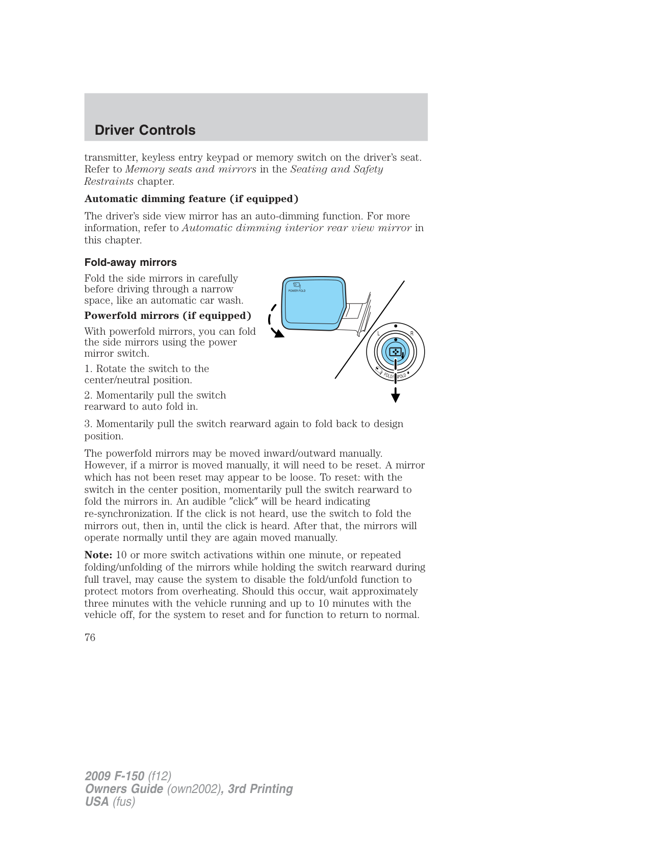
Fold the side mirrors in carefully before driving through a narrow space, like an automatic car wash.
###### Powerfold mirrors (if equipped)
With powerfold mirrors, you can fold the side mirrors using the power mirror switch.
The powerfold mirrors may be moved inward/outward manually. However, if a mirror is moved manually, it will need to be reset. A mirror which has not been reset may appear to be loose. To reset: with the switch in the center position, momentarily pull the switch rearward to fold the mirrors in. An audible click will be heard indicating re-synchronization. If the click is not heard, use the switch to fold the mirrors out, then in, until the click is heard. After that, the mirrors will operate normally until they are again moved manually.
Note: 10 or more switch activations within one minute, or repeated folding/unfolding of the mirrors while holding the switch rearward during full travel, may cause the system to disable the fold/unfold function to protect motors from overheating. Should this occur, wait approximately three minutes with the vehicle running and up to 10 minutes with the vehicle off, for the system to reset and for function to return to normal.
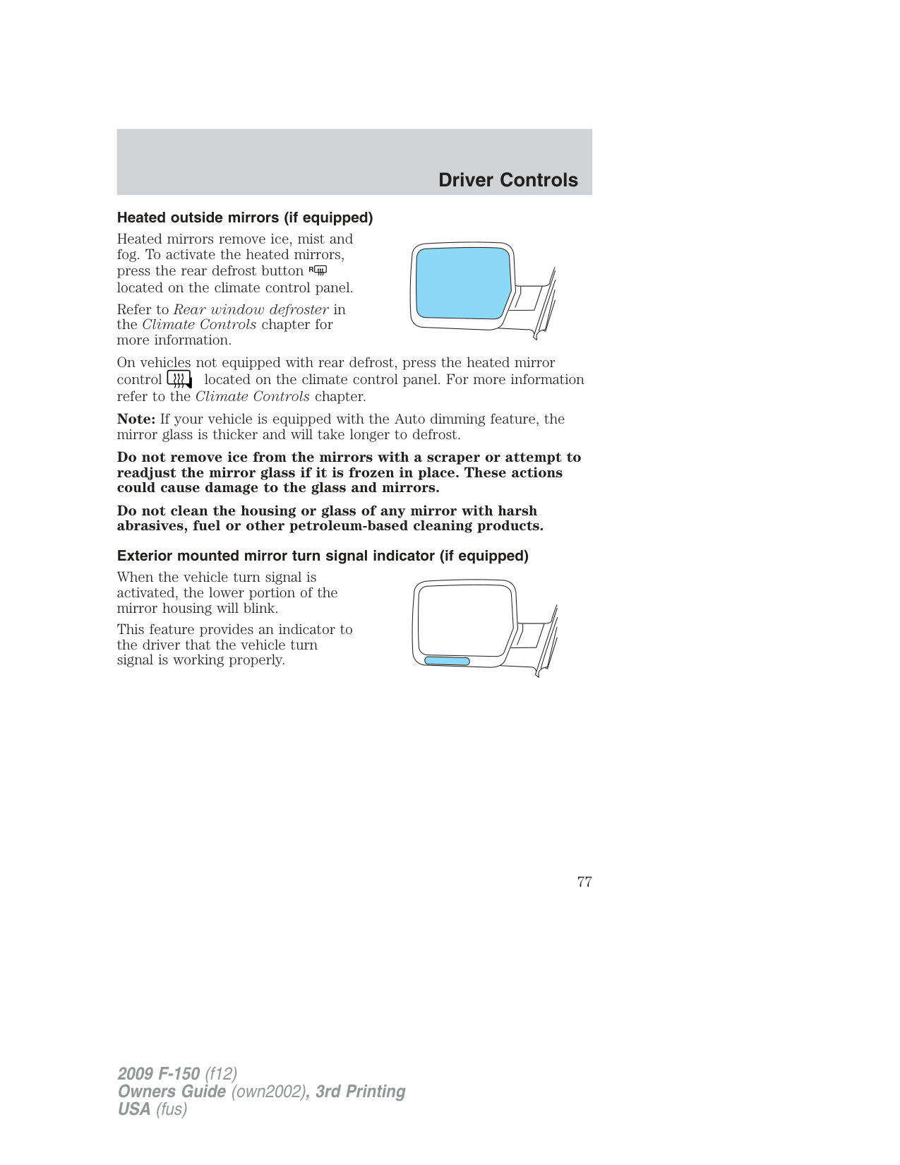
Heated outside mirrors (if equipped) Heated mirrors remove ice, mist and fog. To activate the heated mirrors, press the rear defrost button R located on the climate control panel. Refer to Rear window defroster in the Climate Controls chapter for more information. On vehicles not equipped with rear defrost, press the heated mirror control located on the climate control panel. For more information refer to the Climate Controls chapter. Note: If your vehicle is equipped with the Auto dimming feature, the mirror glass is thicker and will take longer to defrost.
Do not remove ice from the mirrors with a scraper or attempt to readjust the mirror glass if it is frozen in place. These actions could cause damage to the glass and mirrors.
Do not clean the housing or glass of any mirror with harsh abrasives, fuel or other petroleum-based cleaning products.
Exterior mounted mirror turn signal indicator (if equipped)
When the vehicle turn signal is activated, the lower portion of the mirror housing will blink.
This feature provides an indicator to the driver that the vehicle turn signal is working properly.
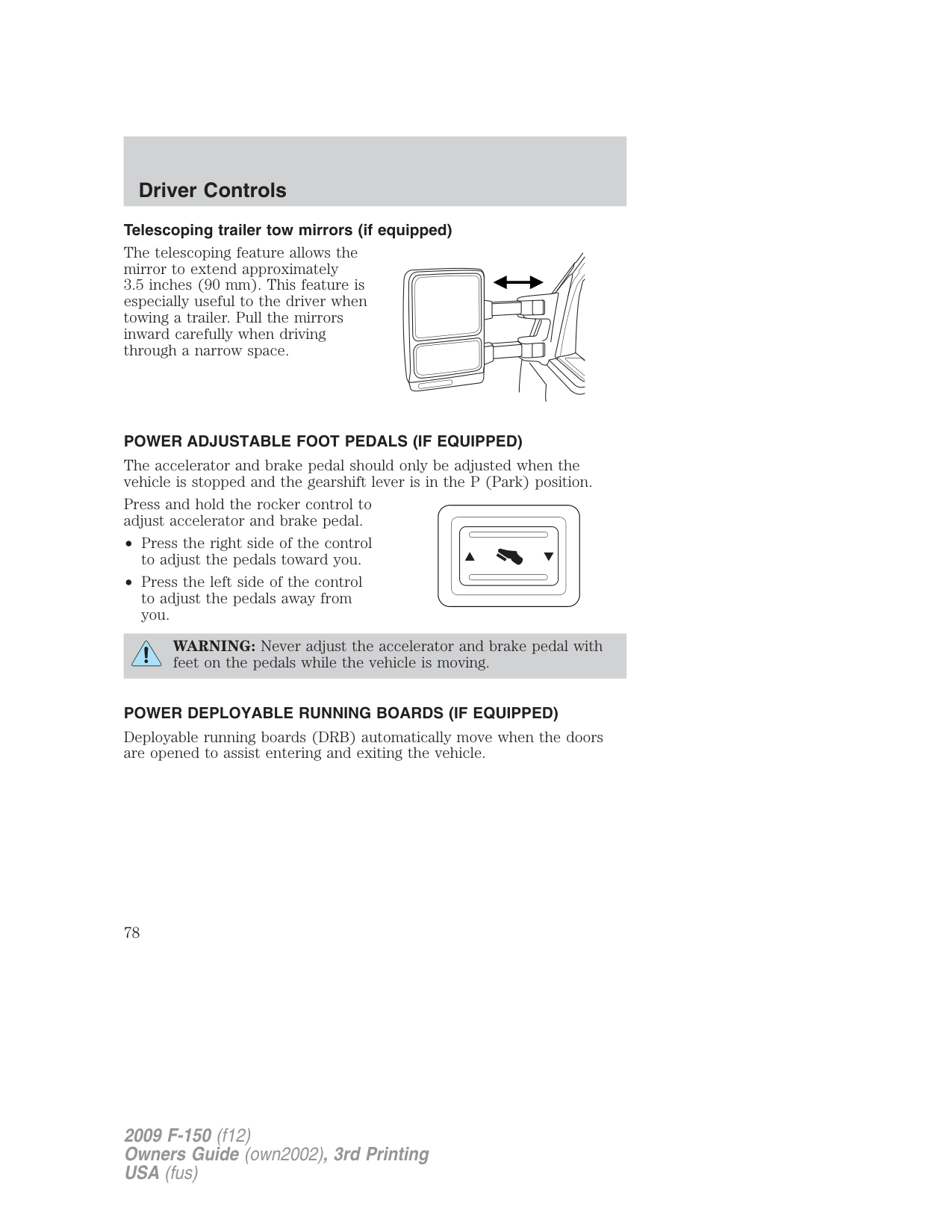
###### Telescoping trailer tow mirrors (if equipped)
The telescoping feature allows the mirror to extend approximately
###### POWER ADJUSTABLE FOOT PEDALS (IF EQUIPPED)
The accelerator and brake pedal should only be adjusted when the vehicle is stopped and the gearshift lever is in the P (Park) position.
Press and hold the rocker control to adjust accelerator and brake pedal.
WARNING: Never adjust the accelerator and brake pedal with feet on the pedals while the vehicle is moving.
###### POWER DEPLOYABLE RUNNING BOARDS (IF EQUIPPED)
Deployable running boards (DRB) automatically move when the doors are opened to assist entering and exiting the vehicle.
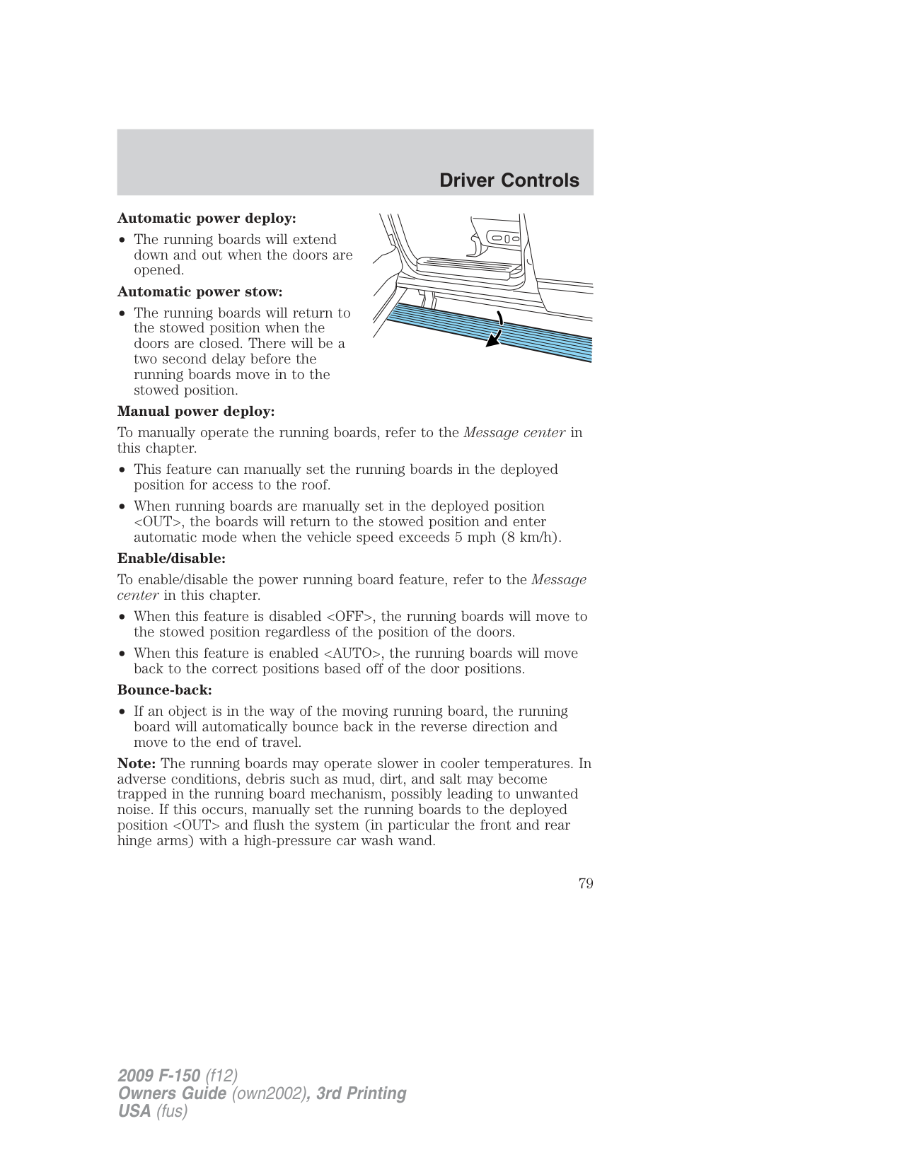
###### Automatic power deploy:
• The running boards will extend down and out when the doors are opened.
###### Automatic power stow:
• The running boards will return to the stowed position when the doors are closed. There will be a two second delay before the running boards move in to the stowed position.
###### Manual power deploy:
To manually operate the running boards, refer to the Message center in this chapter.
• This feature can manually set the running boards in the deployed
position for access to the roof.
• When running boards are manually set in the deployed position
Enable/disable: To enable/disable the power running board feature, refer to the Message center in this chapter.
###### Bounce-back:
• If an object is in the way of the moving running board, the running board will automatically bounce back in the reverse direction and move to the end of travel.
Note: The running boards may operate slower in cooler temperatures. In adverse conditions, debris such as mud, dirt, and salt may become trapped in the running board mechanism, possibly leading to unwanted noise. If this occurs, manually set the running boards to the deployed position
Note: Do not use the running boards, front and rear hinge assemblies, running board motors, or the running board under body mounts to lift the vehicle when jacking. Please utilize proper jacking points. Refer to Changing the tires in the Roadside Emergencies chapter.
WARNING: In extreme climates, excessive ice buildup may occur, causing the running boards not to deploy. Be sure that the
running boards have deployed, and have finished moving before attempting to step on them. Note: The running boards will resume normal function once the blockage is cleared.
WARNING: Turn off the running boards before jacking or placing any object under the vehicle. Never place your hand
between the extended running board and the vehicle. A moving running board may cause injury.
###### SPEED CONTROL (IF EQUIPPED)
With speed control set, you can maintain a set speed without keeping your foot on the accelerator pedal.
WARNING: Do not use the speed control in heavy traffic or on roads that are winding, slippery or unpaved.
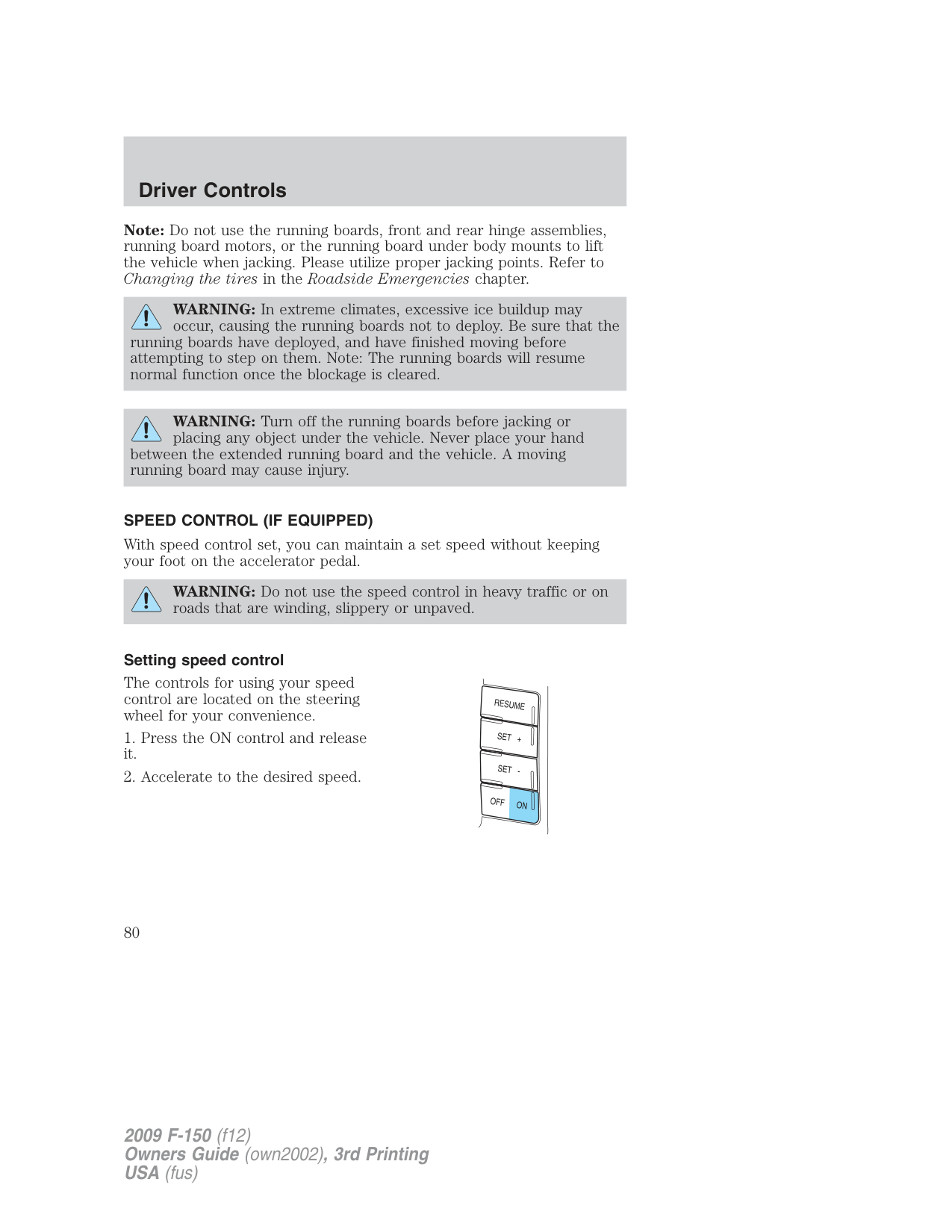
###### Setting speed control
The controls for using your speed control are located on the steering wheel for your convenience.
###### Note:
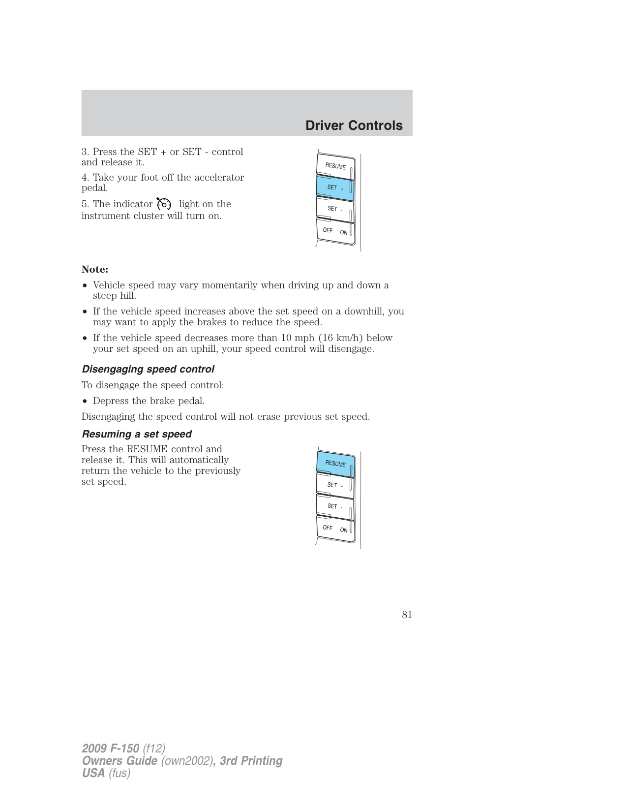
###### Resuming a set speed
Press the RESUME control and release it. This will automatically return the vehicle to the previously set speed.
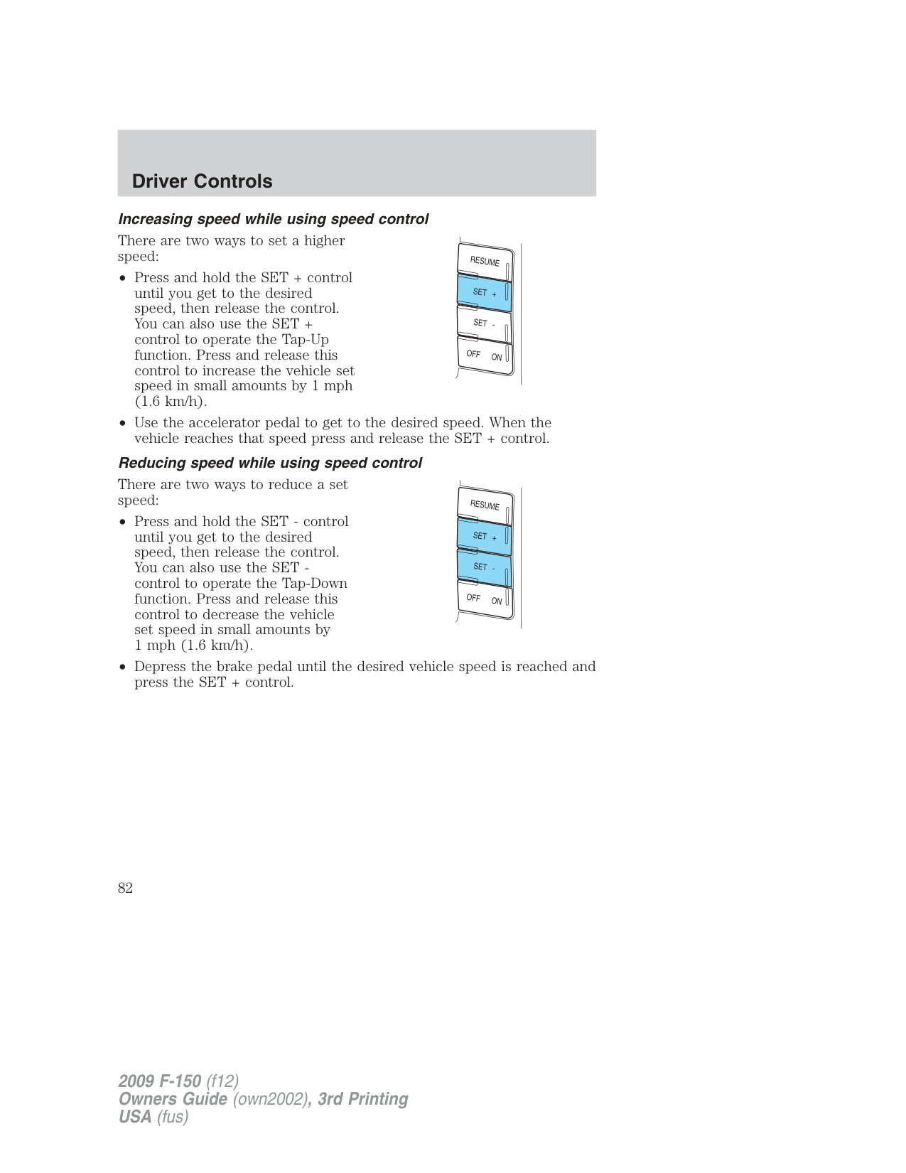
###### Increasing speed while using speed control
There are two ways to set a higher speed:
###### Reducing speed while using speed control
There are two ways to reduce a set speed:
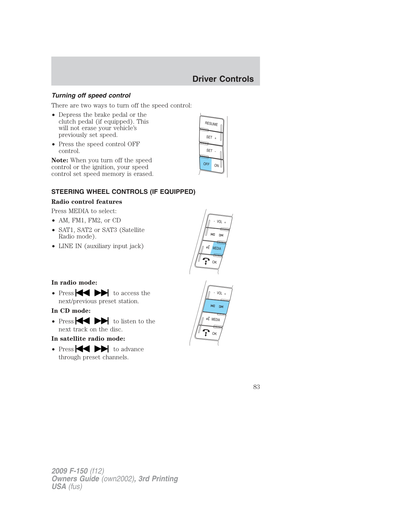
Turning off speed control There are two ways to turn off the speed control:
Note: When you turn off the speed control or the ignition, your speed control set speed memory is erased.
STEERING WHEEL CONTROLS (IF EQUIPPED) Radio control features Press MEDIA to select:
In radio mode:
###### In CD mode:
• Press to listen to the
next track on the disc.
###### In satellite radio mode:
• Press to advance
through preset channels.
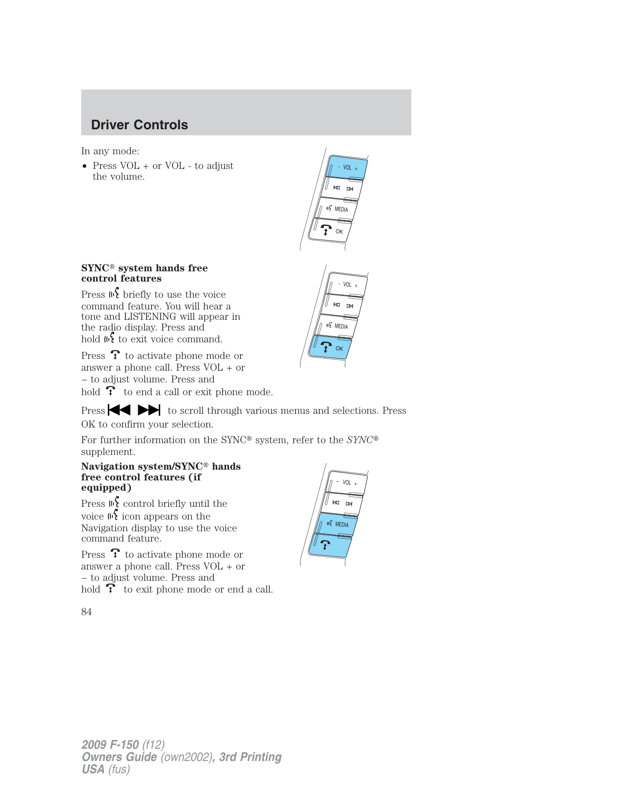
In any mode:
• Press VOL + or VOL - to adjust
the volume.
SYNC system hands free control features
Press briefly to use the voice command feature. You will hear a tone and LISTENING will appear in the radio display. Press and hold to exit voice command.
Press to activate phone mode or answer a phone call. Press VOL + or − to adjust volume. Press and
hold to end a call or exit phone mode. Press to scroll through various menus and selections. Press OK to confirm your selection. For further information on the SYNC system, refer to the SYNC supplement.
Navigation system/SYNC hands free control features (if equipped)
Press control briefly until the voice icon appears on the Navigation display to use the voice command feature.
Press to activate phone mode or answer a phone call. Press VOL + or − to adjust volume. Press and hold to exit phone mode or end a call.
For further information on the Navigation system/SYNC system, refer to the Navigation and SYNC supplements.
MOON ROOF (IF EQUIPPED) The moon roof control is located on the overhead console.
WARNING: Do not let children play with the moon roof or leave children unattended in the vehicle. They may seriously hurt
themselves.
WARNING: When closing the moon roof, you should verify that it is free of obstructions and ensure that children and/or pets are
not in the proximity of the moon roof opening.
The moon roof is equipped with an automatic, one-touch, express opening and closing feature. To stop motion at any time during the one-touch operation, press the control a second time.
To open the moon roof: Press and release the SLIDE control, the moon roof will open automatically. Press the switch again to stop the moon roof.
| | | | |---|---|---| | | | |
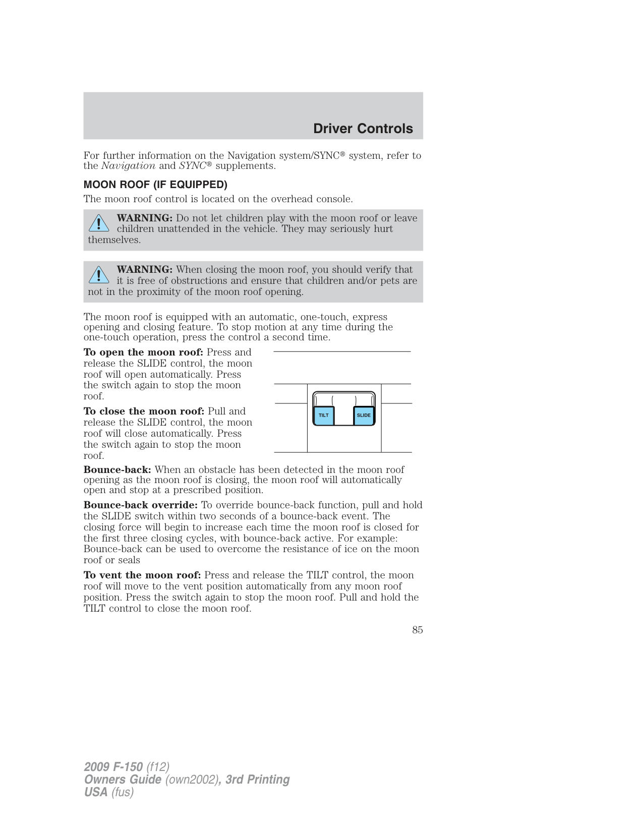
To close the moon roof: Pull and release the SLIDE control, the moon roof will close automatically. Press the switch again to stop the moon roof. Bounce-back: When an obstacle has been detected in the moon roof opening as the moon roof is closing, the moon roof will automatically open and stop at a prescribed position. Bounce-back override: To override bounce-back function, pull and hold the SLIDE switch within two seconds of a bounce-back event. The closing force will begin to increase each time the moon roof is closed for the first three closing cycles, with bounce-back active. For example: Bounce-back can be used to overcome the resistance of ice on the moon roof or seals To vent the moon roof: Press and release the TILT control, the moon roof will move to the vent position automatically from any moon roof position. Press the switch again to stop the moon roof. Pull and hold the TILT control to close the moon roof.
The moon roof has a built-in sliding shade that can be manually opened or closed when the glass panel is shut. To close the shade, pull it toward the front of the vehicle.
HOMELINK WIRELESS CONTROL SYSTEM (IF EQUIPPED) The HomeLink Wireless Control System, located on the driver’s visor, provides a convenient way to replace up to three hand-held transmitters with a single built-in device. This feature will learn the radio frequency codes of most transmitters to operate garage doors, entry gate operators, security systems, entry door locks, and home or office lighting.
WARNING: When programming your HomeLink Wireless Control System to a garage door or gate, be sure that people and
objects are out of the way to prevent potential injury or damage.
Do not use the HomeLink Wireless Control System with any garage door opener that lacks safety stop and reverse features as required by U.S. federal safety standards (this includes any garage door opener model manufactured before April 1, 1982). A garage door which cannot detect an object, signaling the door to stop and reverse, does not meet current U.S. federal safety standards. For more information, contact HomeLink at: www.homelink.com or 1–800–355–3515. Retain the original transmitter for use in other vehicles as well as for future programming procedures (i.e. new HomeLink equipped vehicle purchase). It is also suggested that upon the sale of the vehicle, the programmed Homelink buttons be erased for security purposes, refer to Programming in this section.
Programming Do not program HomeLink with the vehicle parked in the garage. Note: Your vehicle may require the ignition switch to be turned to the accessory position for programming and/or operation of the HomeLink . It is also recommended that a new battery be placed in the hand-held transmitter of the device being programmed to HomeLink for quicker training and accurate transmission of the radio-frequency signal.
Note: Some entry gates and garage door openers may require you to
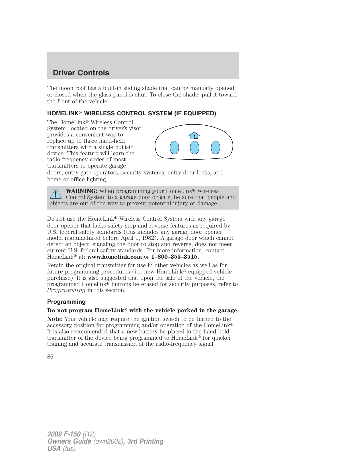
replace Step 2 with procedures noted in the Gate Operator and Canadian Programming in this section for Canadian residents.
6 to complete programming of a rolling code equipped device (most commonly a garage door opener).
HomeLink should now activate your rolling code equipped device. To program additional HomeLink buttons begin with Step 1 in this section. For questions or comments, please contact HomeLink at www.homelink.com or 1–800–355–3515.
###### Gate Operator & Canadian Programming
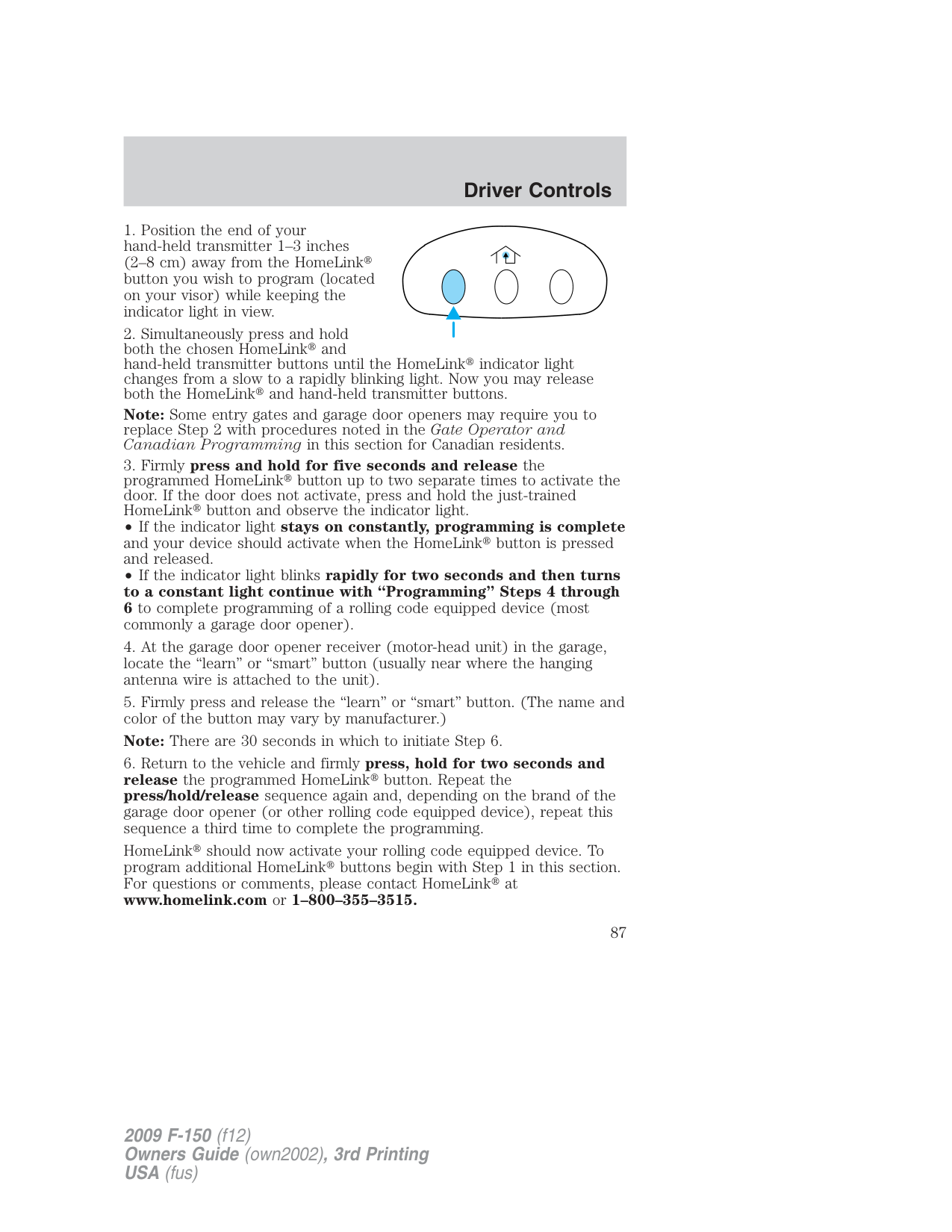
During programming, your hand-held transmitter may automatically stop transmitting not allowing enough time for HomeLink to accept the signal from the hand-held transmitter.
After completing Step 1 outlined in the Programming section, replace Step 2 with the following:
Note: If programming a garage door opener or gate operator, it is advised to unplug the device during the “cycling” process to prevent overheating.
###### Operating the HomeLink Wireless Control System
To operate, simply press and release the appropriate HomeLink button. Activation will now occur for the trained product (garage door, gate operator, security system, entry door lock, or home or office lighting etc.). For convenience, the hand-held transmitter of the device may also be used at any time. In the event that there are still programming difficulties, contact HomeLink at www.homelink.com or 1–800–355–3515.
###### Erasing HomeLink buttons
To erase the three programmed buttons (individual buttons cannot be erased):
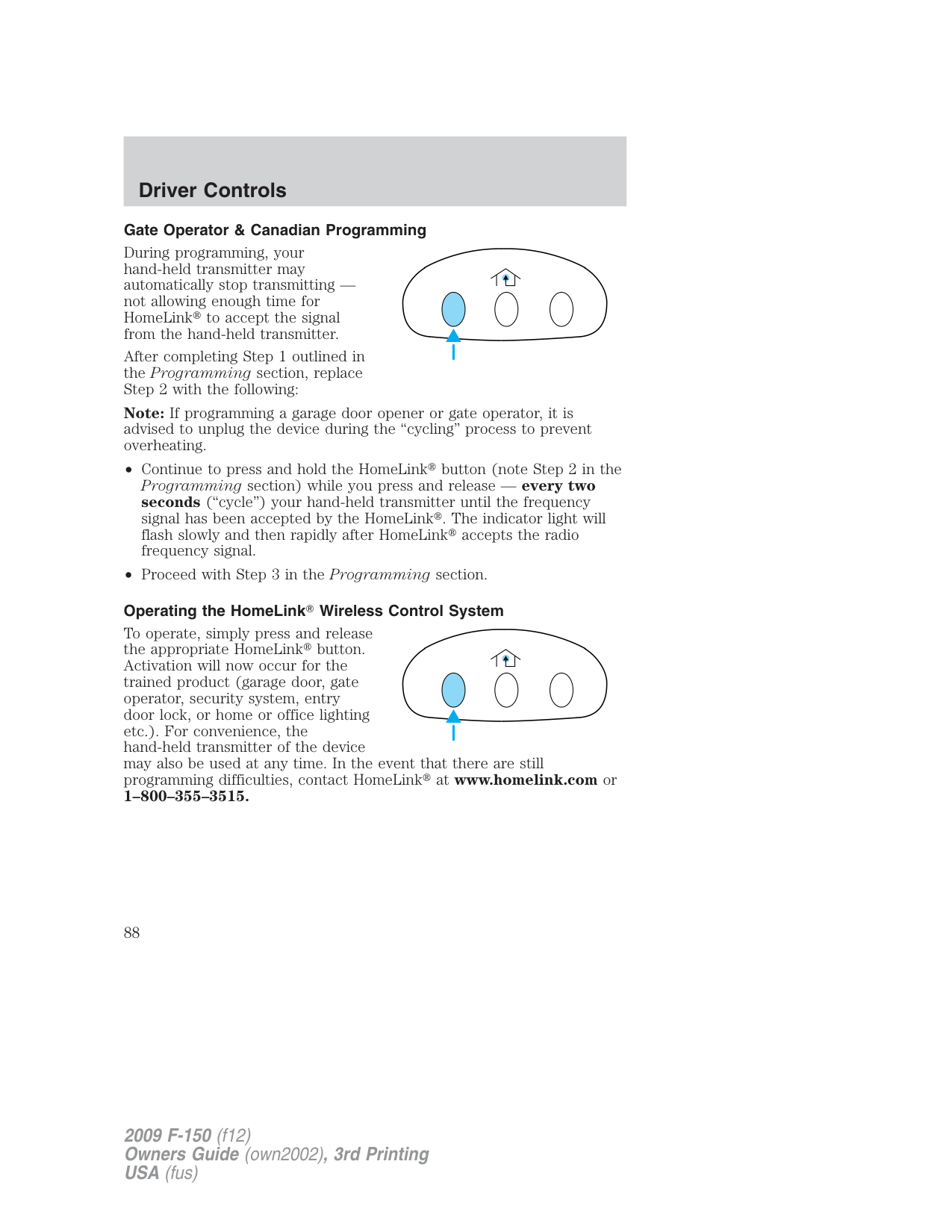
HomeLink is now in the train (or learning) mode and can be programmed at any time beginning with Step 1 in the Programming section.
Reprogramming a single HomeLink button To program a device to HomeLink using a HomeLink button previously trained, follow these steps:
For questions or comments, contact HomeLink at www.homelink.com or 1–800–355–3515.
###### STANDARD MESSAGE CENTER (IF EQUIPPED)
With the ignition in the on position, the message center, located on your instrument cluster, displays important vehicle information through a constant monitor of vehicle systems. You may select display features on the message center for a display of status preceded by a brief indicator chime. The system will also notify you of potential vehicle problems with a display of system warnings followed by a long indicator chime.
###### Selectable features
Press and release the SELECT/RESET stem, located in the speedometer, to scroll and reset the following functions. Select or reset the function by pressing and holding the SELECT/RESET stem for more than two seconds.
Info menu This menu displays the following:
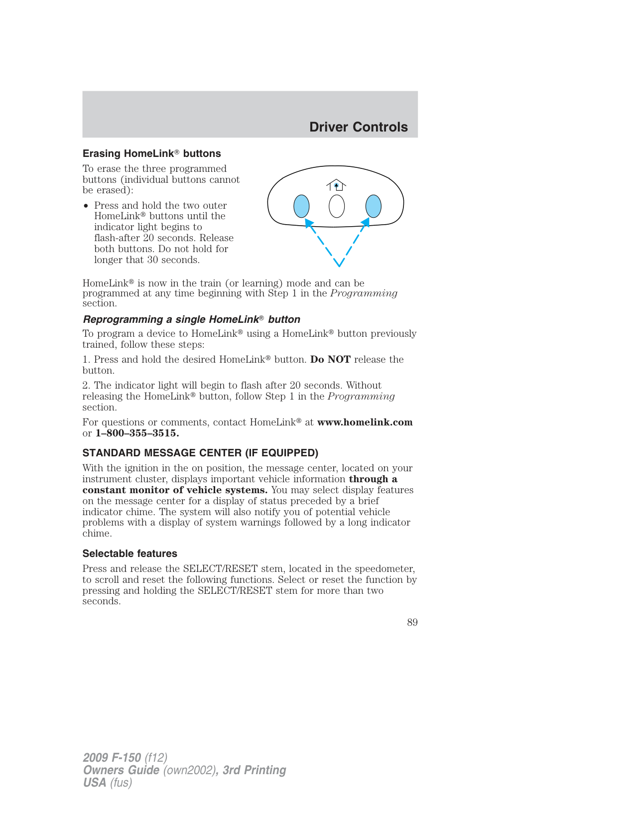
Select this function to estimate approximately how far you can drive with the fuel remaining in your tank under normal driving conditions. Remember to turn the ignition off when refueling to allow this feature to correctly detect the added fuel.
The DTE function will display XXX MILES TO E FUEL LEVEL LOW and sound a chime for one second when you have approximately 50 miles (80 km) to empty. If you RESET this warning message, this display and chime will return within 10 minutes.
DTE is calculated using a running average fuel economy, which is based on your recent driving history of 500 miles (800 km). This value is not the same as the average fuel economy display. The running average fuel economy is re-initialized to a factory default value if the battery is disconnected.
Average fuel economy (AFE)
Select this function from the INFO menu to display your average fuel economy in miles/gallon or liters/100 km.
If you calculate your average fuel economy by dividing miles traveled by gallons of fuel used (liters of fuel used by 100 kilometers traveled), your figure may be different than displayed for the following reasons:
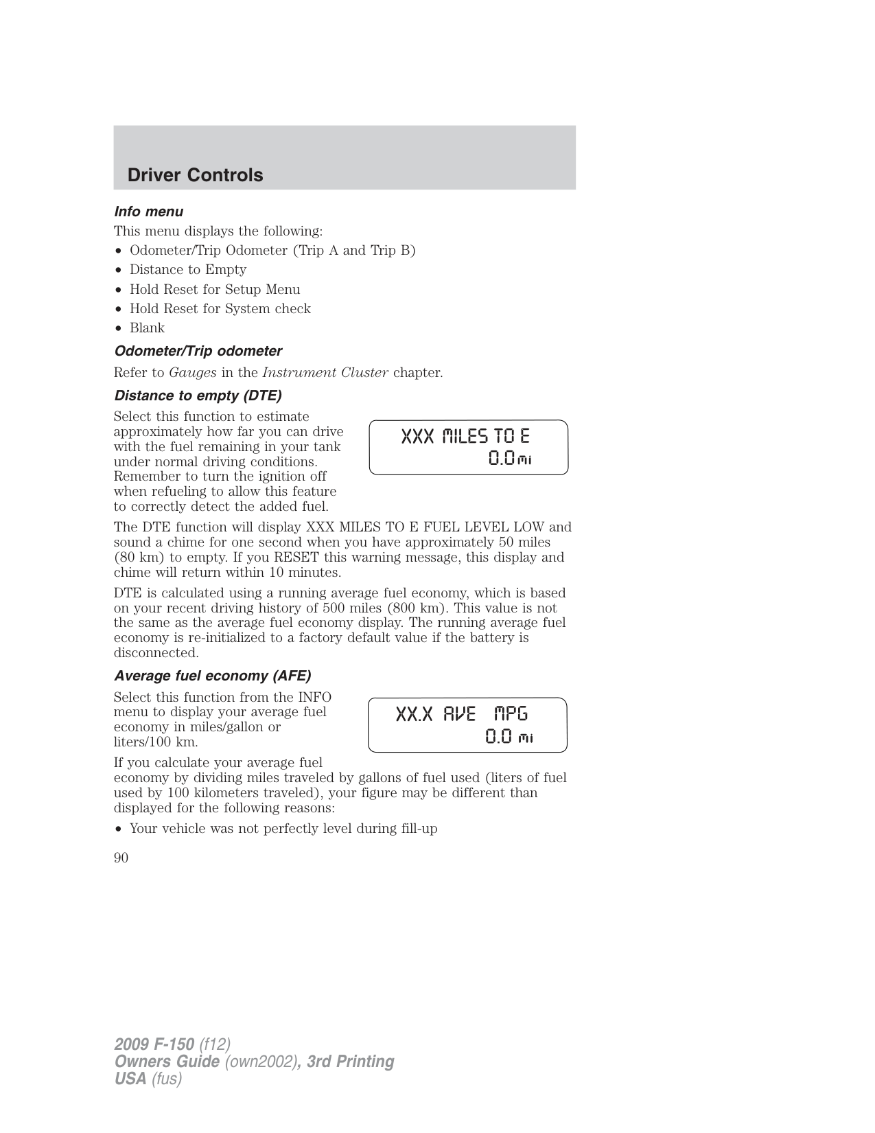
It is important to press the SELECT/RESET stem (press and hold for two seconds in order to reset the function) after setting the speed control to get accurate highway fuel economy readings.
###### Setup Menu
Press and hold the SELECT/RESET stem to get into the SETUP menu sequence from the INFO menu for the following items:

Note: When returning to the SETUP menu and a non-English language has been selected, HOLD RESET FOR ENGLISH will be displayed to change back to English. Press and hold the SELECT/RESET stem to change back to English.
###### Oil Life XXX% HOLD RESET = NEW
An oil change is required whenever indicated by the message center. USE ONLY RECOMMENDED ENGINE OILS.
To reset the oil monitoring system to 100% after each oil change [approximately 7,500 miles (12,000 km) or six months] perform the following:
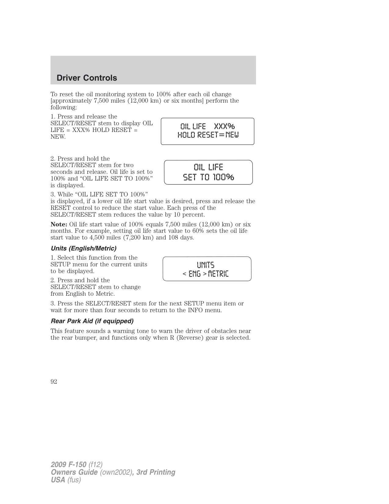
Note: Oil life start value of 100% equals 7,500 miles (12,000 km) or six months. For example, setting oil life start value to 60% sets the oil life start value to 4,500 miles (7,200 km) and 108 days.
###### Units (English/Metric)
This feature sounds a warning tone to warn the driver of obstacles near the rear bumper, and functions only when R (Reverse) gear is selected.
This feature keeps your headlights on for up to three minutes after the ignition is switched off.
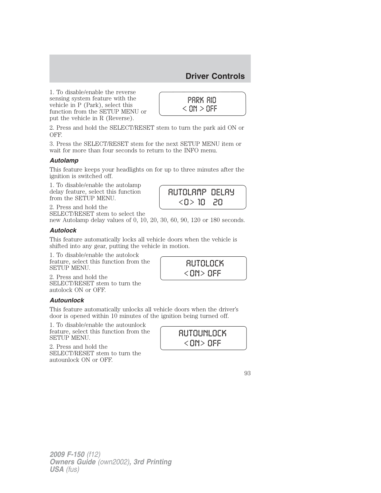
This feature automatically locks all vehicle doors when the vehicle is shifted into any gear, putting the vehicle in motion.
This feature automatically unlocks all vehicle doors when the driver’s door is opened within 10 minutes of the ignition being turned off.
###### Easy Entry (if equipped)
This feature automatically moves the drivers seat backwards for easy exit from the vehicle.
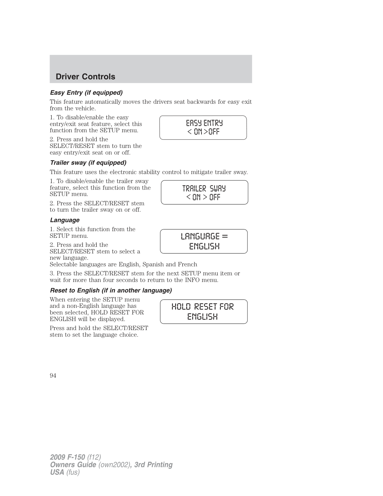
When entering the SETUP menu and a non-English language has been selected, HOLD RESET FOR ENGLISH will be displayed.
Press and hold the SELECT/RESET stem to set the language choice.
###### RESET FOR SYSTEM CHECK
Press and hold the SELECT/RESET stem to get into the system check sequence from the INFO menu for the following items:
The message center will cycle through each of the systems being monitored. For each of the monitored systems, the message center will indicate either an OK message or a warning message for two seconds.
The sequence of the system check report and how it appears in the message center is as follows:
System warnings alert you to possible problems or malfunctions in your vehicle’s operating systems.
In the event of a multiple warning situation, the message center will cycle the display to show all warnings by displaying each one for four seconds.
The message center will display the last selected feature if there are no more warning messages. This allows you to use the full functionality of the message center after you acknowledge the warning by pressing the SELECT/RESET stem and clearing the warning message.

Warning messages can be divided into three categories:
|Warning display|Status| |---|---| |Driver door ajar|The warning can return after the ignition key is turned from off to on if the condition still exists.| |Passenger door ajar|The warning can return after the ignition key is turned from off to on if the condition still exists.| |Rear left door ajar|The warning can return after the ignition key is turned from off to on if the condition still exists.| |Rear right door ajar|The warning can return after the ignition key is turned from off to on if the condition still exists.| |XXX miles to E fuel level low|The warning can be reset. If the condition/problem occurs again, the message can return after being reset. The warning can return after the ignition key is turned from off to on if the condition/problem still exists.| |Check charging system|The warning can be reset. If the condition/problem occurs again, the message can return after being reset. The warning can return after the ignition key is turned from off to on if the condition/problem still exists.| |Tire pressure sensor fault|The warning can be reset. If the condition/problem occurs again, the message can return after being reset. The warning can return after the ignition key is turned from off to on if the condition/problem still exists.| |Low tire pressure|The warning can be reset. If the condition/problem occurs again, the message can return after being reset. The warning can return after the ignition key is turned from off to on if the condition/problem still exists.| |Service RSC now|The warning can be reset. If the condition/problem occurs again, the message can return after being reset. The warning can return after the ignition key is turned from off to on if the condition/problem still exists.| |Check fuel fill inlet|The warning can be reset. If the condition/problem occurs again, the message can return after being reset. The warning can return after the ignition key is turned from off to on if the condition/problem still exists.| |Check 4x4 (if equipped)|The warning can be reset. If the condition/problem occurs again, the message can return after being reset. The warning can return after the ignition key is turned from off to on if the condition/problem still exists.|
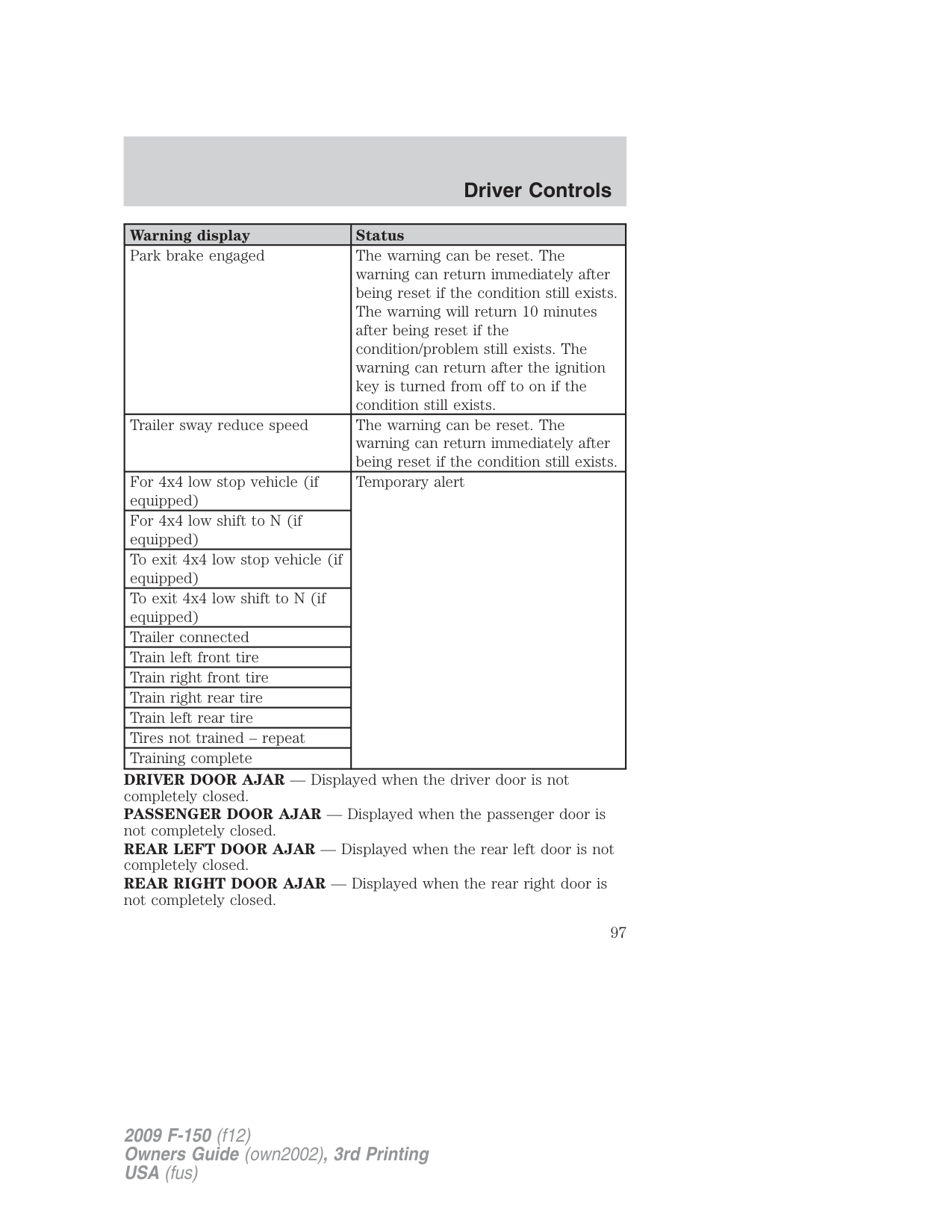
|Tire pressure monitor fault|The warning can be reset. If the condition/problem occurs again, the message can return after being reset. The warning can return after the ignition key is turned from off to on if the condition/problem still exists.| |Brake fluid level low|The warning can be reset. The warning can return after the ignition key is turned from off to on if the condition/problem still exists.| |Trailer brake module fault (if equipped)|The warning can be reset. The warning can return after the ignition key is turned from off to on if the condition/problem still exists.| |Oil change required|The warning can be reset. The warning can return after the ignition key is turned from off to on if the condition/problem still exists.| |XX% Oil life change soon|The warning can be reset. The warning can return after the ignition key is turned from off to on if the condition/problem still exists.| |Wiring fault on trailer (if equipped)|The warning can be reset. The warning can return after the ignition key is turned from off to on if the condition/problem still exists.| |Check rear park aid (if equipped)|The warning can be reset. The warning can return after the ignition key is turned from off to on if the condition/problem still exists.| |Trailer disconnected (if equipped)|The warning can be reset. The warning can return immediately after being reset if the condition/problem still exists. The warning will return 10 minutes after being reset if the condition/problem still exists. The warning can return after the ignition key is turned from off to on if the condition/problem still exists.| |Check brake system|The warning can be reset. The warning can return immediately after being reset if the condition/problem still exists. The warning will return 10 minutes after being reset if the condition/problem still exists. The warning can return after the ignition key is turned from off to on if the condition/problem still exists.|
|Warning display|Status| |---|---| |Park brake engaged|The warning can be reset. The warning can return immediately after being reset if the condition still exists. The warning will return 10 minutes after being reset if the condition/problem still exists. The warning can return after the ignition key is turned from off to on if the condition still exists.| |Trailer sway reduce speed|The warning can be reset. The warning can return immediately after being reset if the condition still exists.| |For 4x4 low stop vehicle (if equipped)|Temporary alert| |For 4x4 low shift to N (if equipped)|Temporary alert| |To exit 4x4 low stop vehicle (if equipped)|Temporary alert| |To exit 4x4 low shift to N (if equipped)|Temporary alert| |Trailer connected|Temporary alert|
|Train left front tire|Temporary alert| |Train right front tire|Temporary alert| |Train right rear tire|Temporary alert| |Train left rear tire|Temporary alert| |Tires not trained – repeat|Temporary alert| |Training complete|Temporary alert|
DRIVER DOOR AJAR — Displayed when the driver door is not completely closed. PASSENGER DOOR AJAR — Displayed when the passenger door is not completely closed. REAR LEFT DOOR AJAR — Displayed when the rear left door is not completely closed. REAR RIGHT DOOR AJAR — Displayed when the rear right door is not completely closed.
XXX MILES TO E FUEL LEVEL LOW — Displayed as an early reminder of a low fuel condition.
CHECK CHARGING SYSTEM — Displayed when the electrical system is not maintaining proper voltage. If you are operating electrical accessories when the engine is idling at a low speed, turn off as many of the electrical loads as soon as possible. If the warning stays on or comes on when the engine is operating at normal speeds, contact your authorized dealer as soon as possible
TIRE PRESSURE SENSOR FAULT — Displayed when a tire pressure sensor is malfunctioning, or your spare tire is in use. For more information on how the system operates under these conditions, refer to Understanding Your Tire Pressure Monitoring System (TPMS) in the Tires, Wheels and Loading chapter. If the warning stays on or continues to come on, contact your authorized dealer as soon as possible
LOW TIRE PRESSURE — Displayed when one or more tires on your vehicle have low tire pressure. Refer to Inflating Your Tires in the Tires, Wheels and Loading chapter.
SERVICE RSC NOW — Displayed when the RSC system is not operating properly. If the warning stays on or continues to come on, contact your authorized dealer as soon as possible.
CHECK FUEL FILL INLET — Displayed when the fuel fill inlet may not be properly closed. Refer to Easy Fuel™ “no cap” fuel system in the Maintenance and Specifications chapter.
CHECK 4X4 (if equipped) — Displayed when a 4X4 system fault is present. For more information, refer to Four-wheel drive (4WD) operation in the Driving chapter.
###### TIRE PRESSURE MONITOR FAULT — Displayed when the Tire
Pressure Monitoring System is malfunctioning. If the warning stays on or continues to come on, contact your authorized dealer as soon as possible
BRAKE FLUID LEVEL LOW — Indicates the brake fluid level is low and the brake system should be inspected immediately. Refer to Brake fluid in the Maintenance and Specifications chapter.
TRAILER BRAKE MODULE FAULT (if equipped) — Displayed and accompanied by a single chime, in response to faults sensed by the TBC. Refer to Trailer towing in the Tires, Wheels and Loading chapter for more information.
OIL CHANGE REQUIRED — Displayed when an oil change is required.
XX% OIL LIFE CHANGE SOON — Displayed when an oil change will soon be required and shows the percentage of oil life left.
WIRING FAULT ON TRAILER (if equipped) — Displayed if there are certain faults in the vehicle wiring and trailer wiring/brake system. Refer to Trailer towing in the Tires, Wheels and Loading chapter for more information.
CHECK REAR PARK AID (if equipped) — Displayed when the transmission is in R (Reverse). Refer to Reverse sensing system in the Driving chapter.
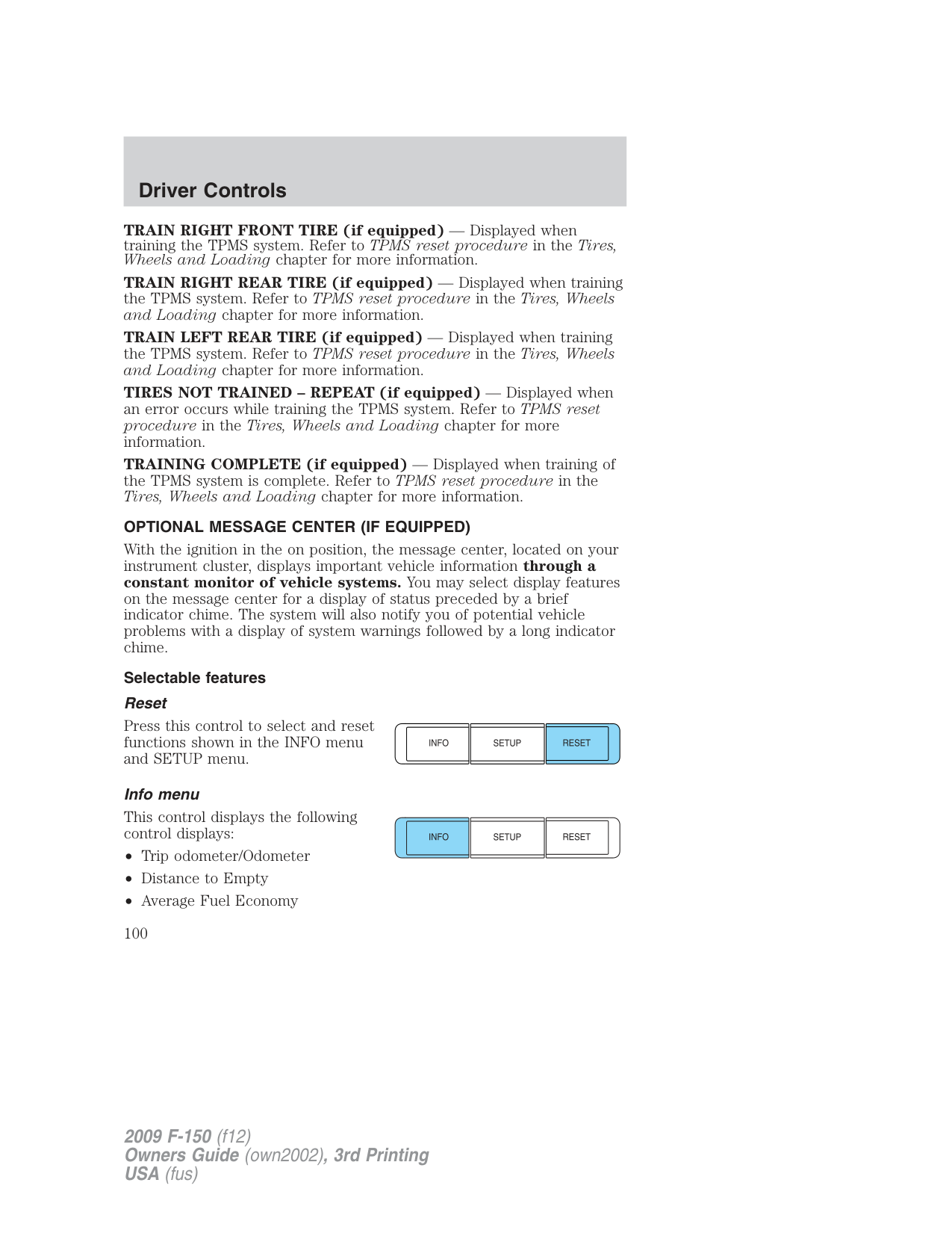
TRAILER DISCONNECTED (if equipped) — Displayed when a trailer connection becomes disconnected, either intentionally or unintentionally, and has been sensed during a given ignition cycle. Refer to Trailer towing in the Tires, Wheels and Loading chapter for more information.
CHECK BRAKE SYSTEM — Displayed when a fault has been detected by the ABS module.
PARK BRAKE ENGAGED — Displayed when the parking brake is engaged.
TRAILER SWAY REDUCE SPEED (if equipped) — Displayed when the trailer sway control has detected trailer sway. For more information, refer to the Driving chapter for more information.
FOR 4X4 LOW STOP VEHICLE (if equipped) — Displayed when 4X4 LOW is selected while the vehicle is moving. For more information, refer to Four-wheel drive (4WD) operation in the Driving chapter.
FOR 4X4 LOW SHIFT TO N (if equipped) — Displayed when 4X4 LOW is selected and the vehicle is stopped. For more information, refer to Four-wheel drive (4WD) operation in the Driving chapter.
TO EXIT 4X4 LOW STOP VEHICLE (if equipped) — Displayed when 2WD is selected while the vehicle is operating in 4X4 LOW. For more information, refer to Four-wheel drive (4WD) operation in the Driving chapter.
TO EXIT 4X4 LOW SHIFT TO N (if equipped) — Displayed when 2WD is selected while the vehicle has been stopped in 4X4 LOW. For more information, refer to Four-wheel drive (4WD) operation in the Driving chapter.
###### TRAILER CONNECTED (if equipped) — Displayed when a correct
trailer connection (a trailer with electric trailer brakes) is sensed during a given ignition cycle. Refer to Trailer towing in the Tires, Wheels and Loading chapter for more information.
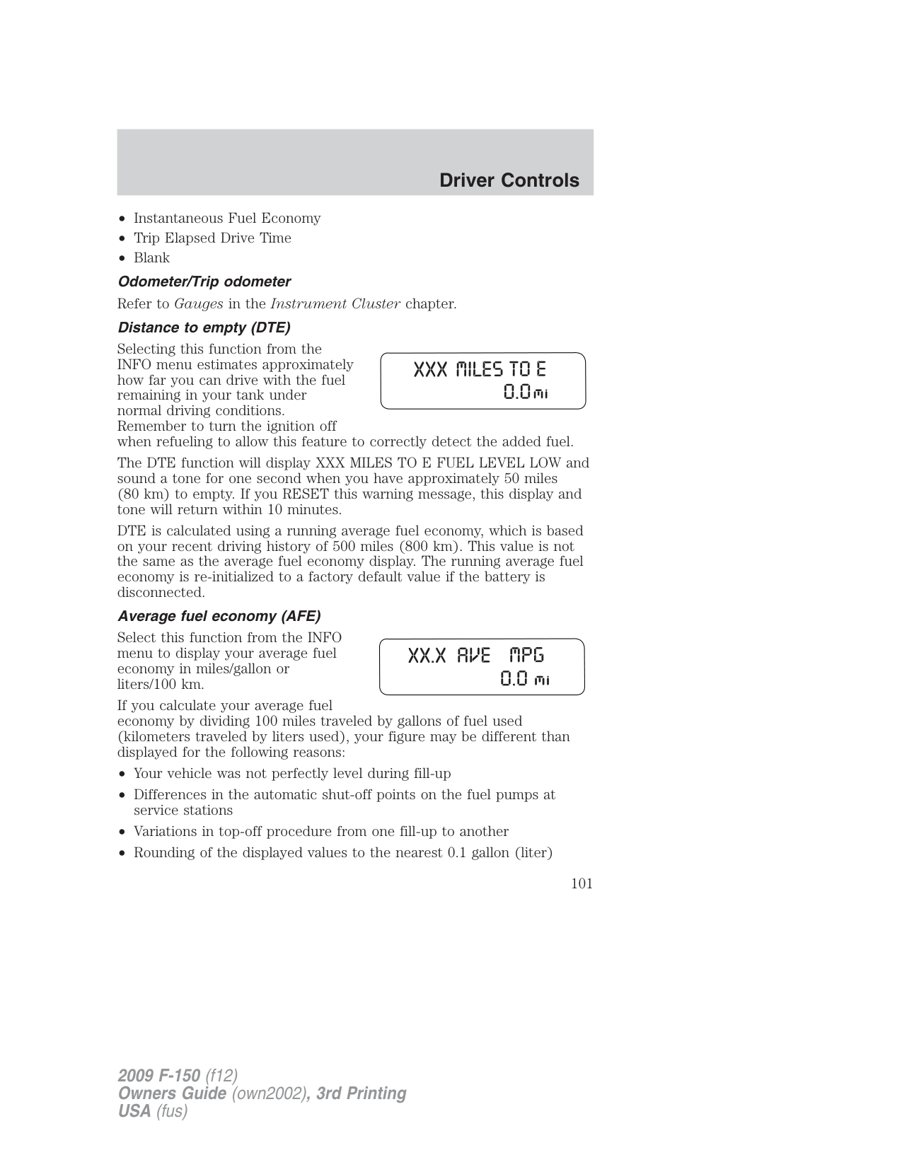
TRAIN LEFT FRONT TIRE (if equipped) — Displayed when training the TPMS system. Refer to TPMS reset procedure in the Tires, Wheels and Loading chapter for more information.
TRAIN RIGHT FRONT TIRE (if equipped) — Displayed when training the TPMS system. Refer to TPMS reset procedure in the Tires, Wheels and Loading chapter for more information.
TRAIN RIGHT REAR TIRE (if equipped) — Displayed when training the TPMS system. Refer to TPMS reset procedure in the Tires, Wheels and Loading chapter for more information.
TRAIN LEFT REAR TIRE (if equipped) — Displayed when training the TPMS system. Refer to TPMS reset procedure in the Tires, Wheels and Loading chapter for more information.
TIRES NOT TRAINED – REPEAT (if equipped) — Displayed when an error occurs while training the TPMS system. Refer to TPMS reset procedure in the Tires, Wheels and Loading chapter for more information.
TRAINING COMPLETE (if equipped) — Displayed when training of the TPMS system is complete. Refer to TPMS reset procedure in the Tires, Wheels and Loading chapter for more information.
###### OPTIONAL MESSAGE CENTER (IF EQUIPPED)
With the ignition in the on position, the message center, located on your instrument cluster, displays important vehicle information through a constant monitor of vehicle systems. You may select display features on the message center for a display of status preceded by a brief indicator chime. The system will also notify you of potential vehicle problems with a display of system warnings followed by a long indicator chime.
Selectable features Reset
Press this control to select and reset functions shown in the INFO menu and SETUP menu.
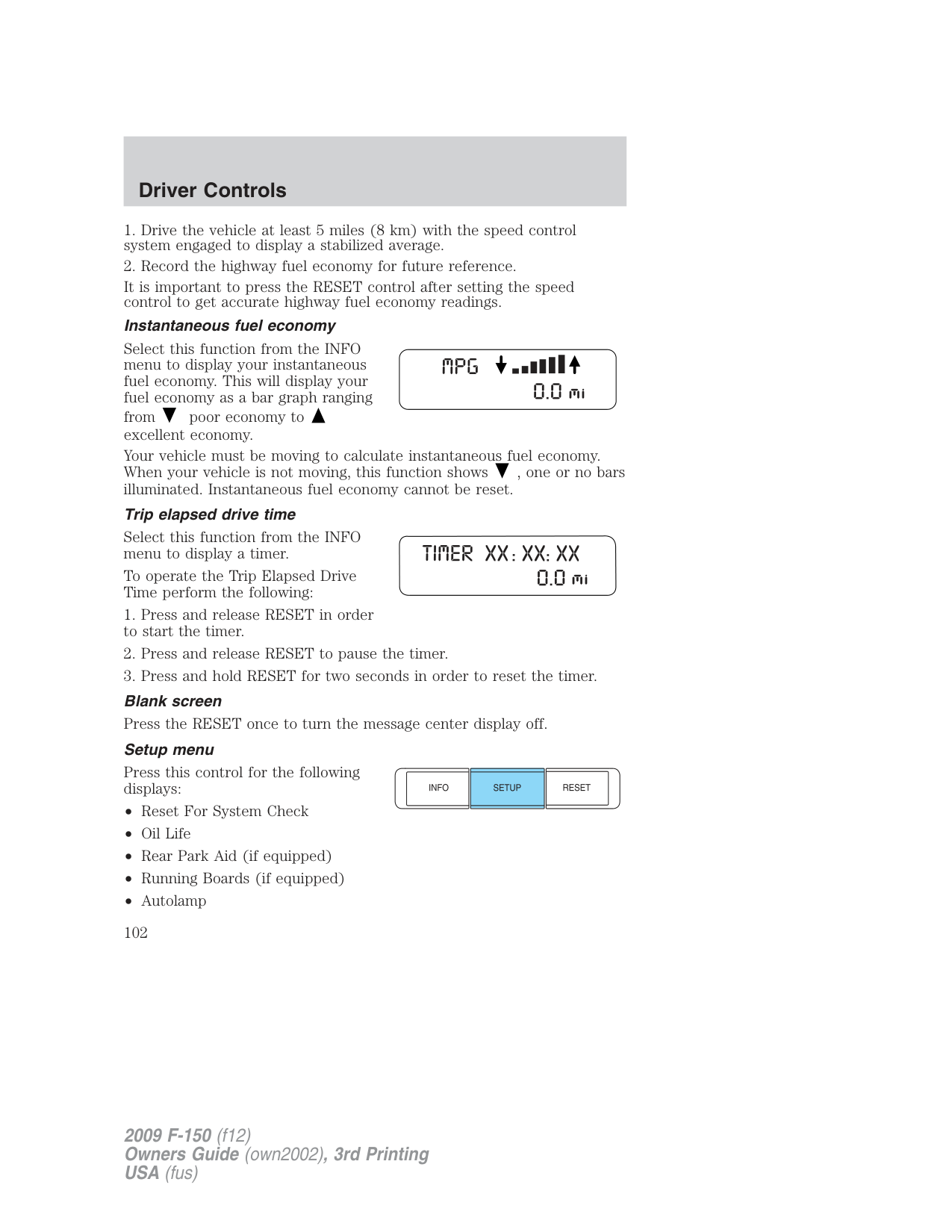
| | |---| | |
###### Info menu
This control displays the following control displays:
| | |---| | |
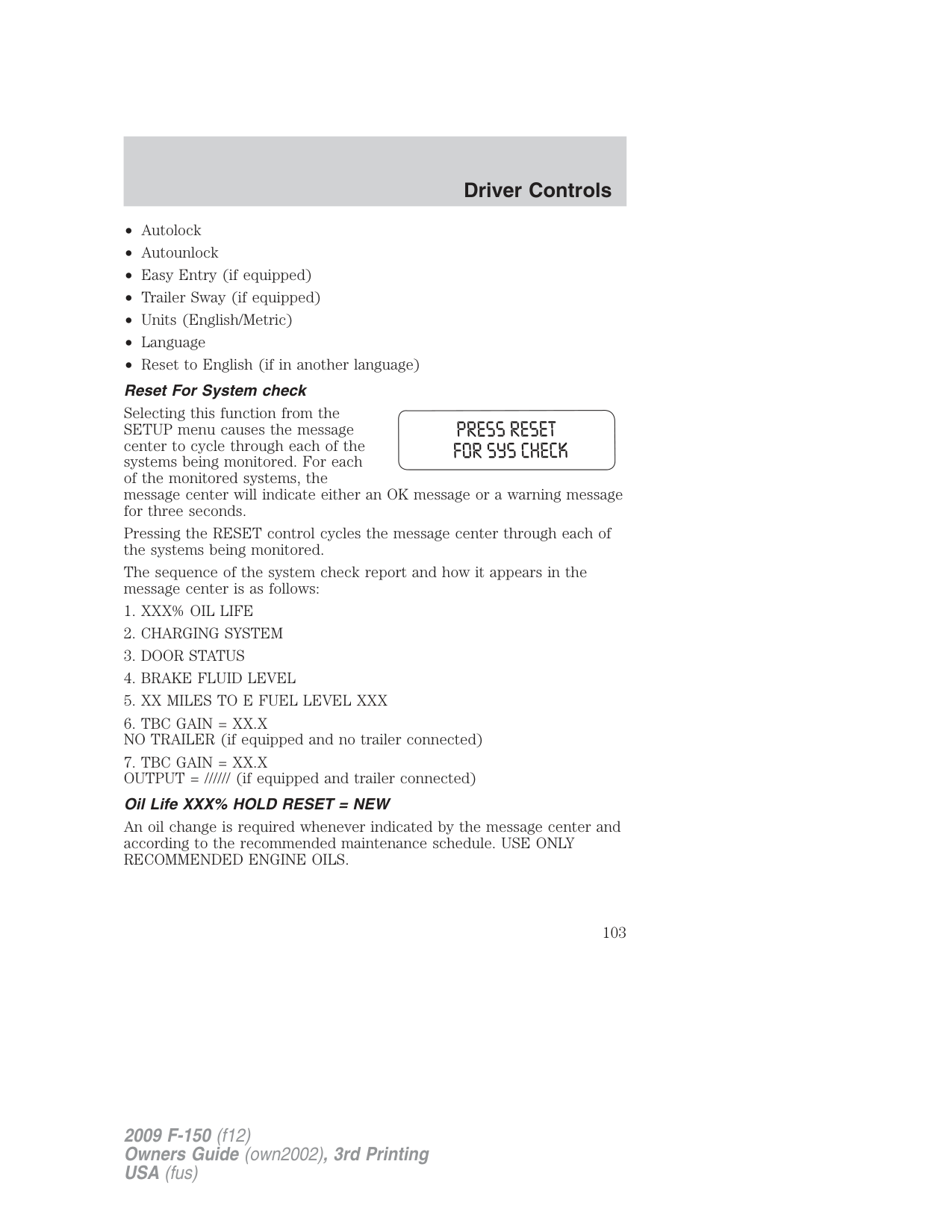
Selecting this function from the INFO menu estimates approximately how far you can drive with the fuel remaining in your tank under normal driving conditions. Remember to turn the ignition off when refueling to allow this feature to correctly detect the added fuel.
The DTE function will display XXX MILES TO E FUEL LEVEL LOW and sound a tone for one second when you have approximately 50 miles (80 km) to empty. If you RESET this warning message, this display and tone will return within 10 minutes.
DTE is calculated using a running average fuel economy, which is based on your recent driving history of 500 miles (800 km). This value is not the same as the average fuel economy display. The running average fuel economy is re-initialized to a factory default value if the battery is disconnected.
Average fuel economy (AFE)
Select this function from the INFO menu to display your average fuel economy in miles/gallon or liters/100 km.
If you calculate your average fuel economy by dividing 100 miles traveled by gallons of fuel used (kilometers traveled by liters used), your figure may be different than displayed for the following reasons:
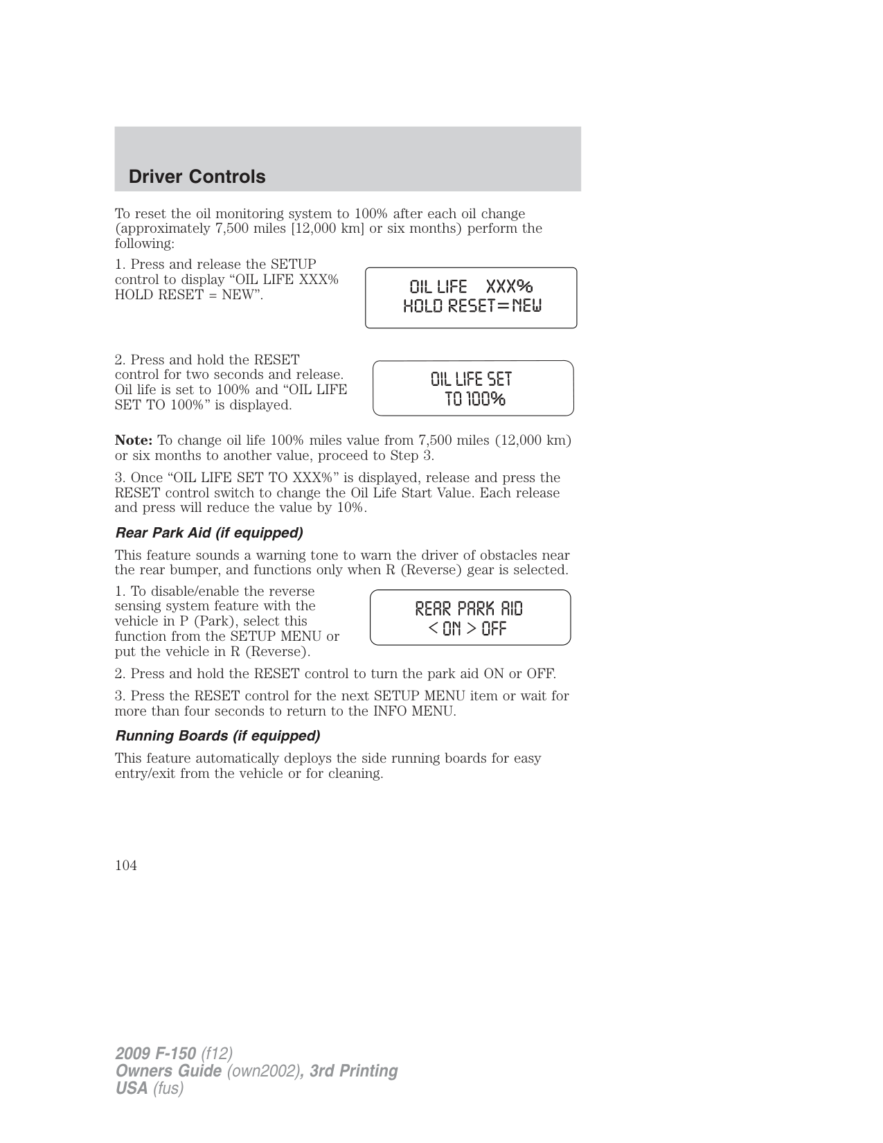
It is important to press the RESET control after setting the speed control to get accurate highway fuel economy readings.
Instantaneous fuel economy Select this function from the INFO menu to display your instantaneous fuel economy. This will display your fuel economy as a bar graph ranging from poor economy to excellent economy. Your vehicle must be moving to calculate instantaneous fuel economy. When your vehicle is not moving, this function shows , one or no bars illuminated. Instantaneous fuel economy cannot be reset. Trip elapsed drive time
Select this function from the INFO menu to display a timer.
To operate the Trip Elapsed Drive Time perform the following:
Press this control for the following displays:
| | |---| | |
Selecting this function from the SETUP menu causes the message center to cycle through each of the systems being monitored. For each of the monitored systems, the message center will indicate either an OK message or a warning message for three seconds.
Pressing the RESET control cycles the message center through each of the systems being monitored.
The sequence of the system check report and how it appears in the message center is as follows:
An oil change is required whenever indicated by the message center and according to the recommended maintenance schedule. USE ONLY RECOMMENDED ENGINE OILS.
To reset the oil monitoring system to 100% after each oil change (approximately 7,500 miles [12,000 km] or six months) perform the following:
Note: To change oil life 100% miles value from 7,500 miles (12,000 km) or six months to another value, proceed to Step 3.
This feature sounds a warning tone to warn the driver of obstacles near the rear bumper, and functions only when R (Reverse) gear is selected.
This feature automatically deploys the side running boards for easy entry/exit from the vehicle or for cleaning.
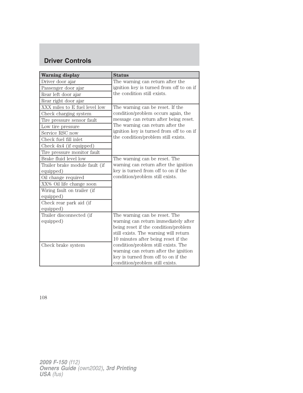
This feature keeps your headlights on for up to three minutes after the ignition is switched off.
This feature automatically locks all vehicle doors when the vehicle is shifted into any gear, putting the vehicle in motion.
This feature automatically unlocks all vehicle doors when the driver’s door is opened within 10 minutes of the ignition being turned off.
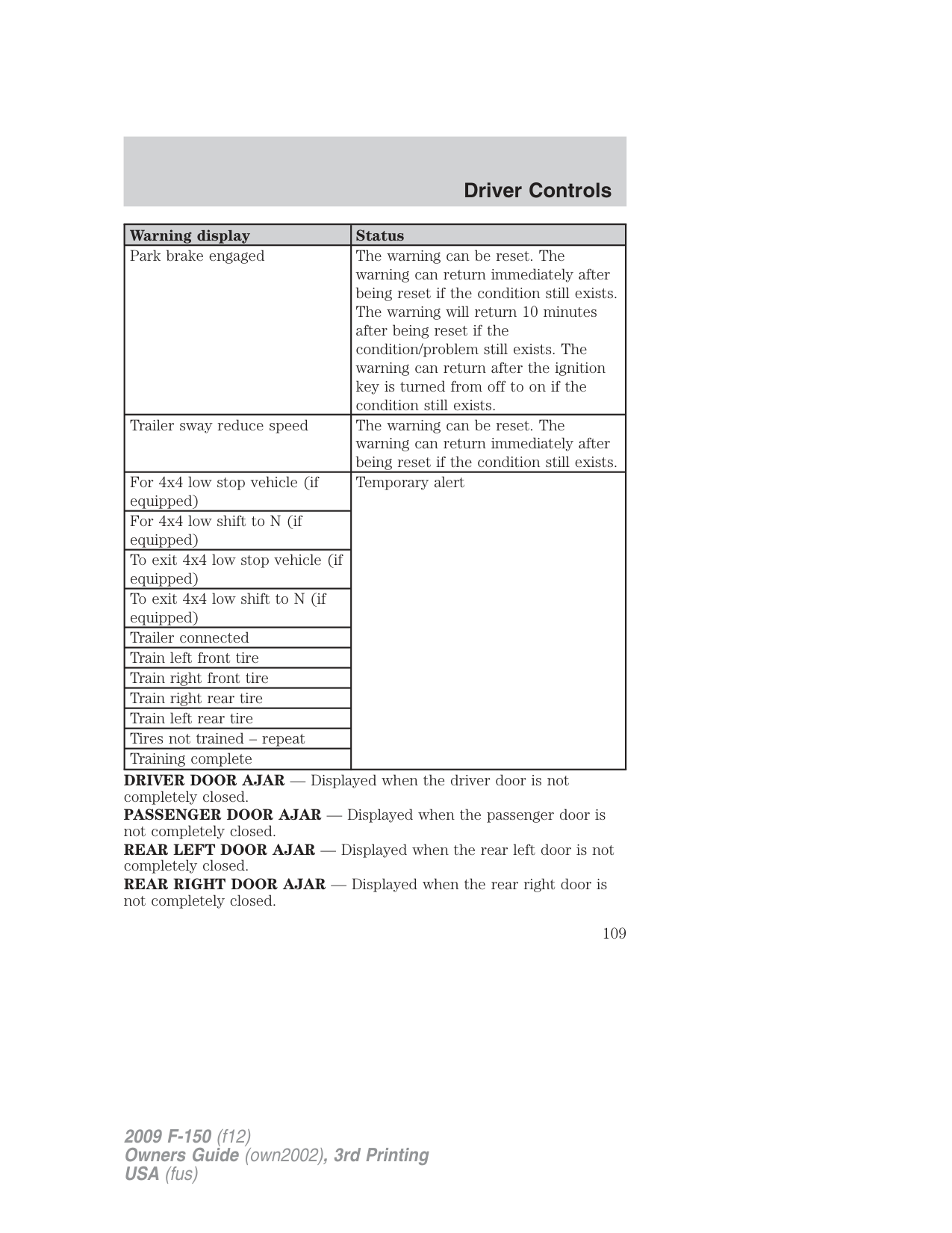
This feature automatically moves the drivers seat backwards for easy exit from the vehicle.
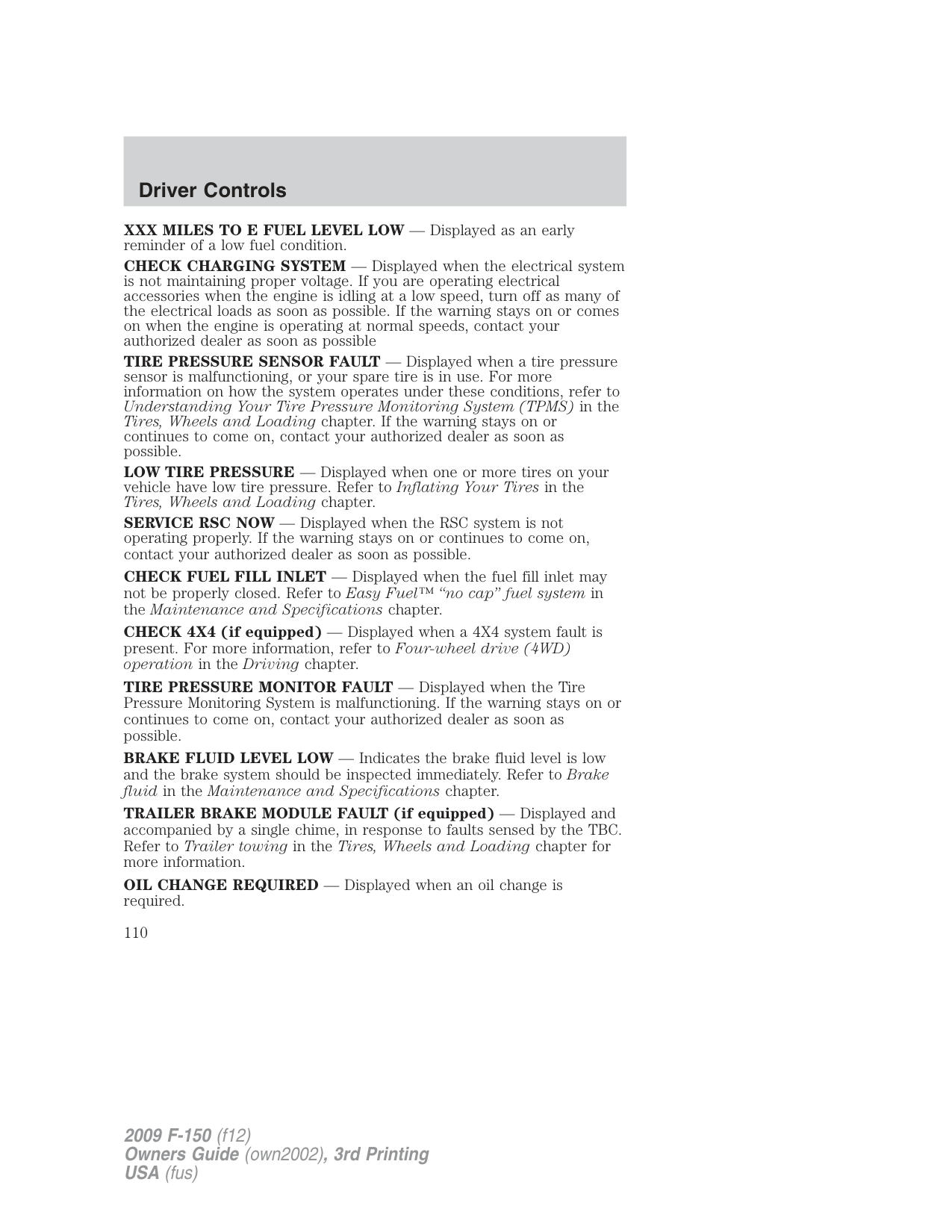
When entering the SETUP MENU and a non-English language has been selected, “HOLD RESET FOR ENGLISH” will be displayed.
Press and hold the RESET control to set the language choice.
###### System warnings
System warnings alert you to possible problems or malfunctions in your vehicle’s operating systems.
In the event of a multiple warning situation, the message center will cycle the display to show all warnings by displaying each one for four seconds.
The message center will display the last selected feature if there are no more warning messages. This allows you to use the full functionality of the message center after you acknowledge the warning by pressing the RESET control and clearing the warning message.
Warning messages can be divided into three categories:
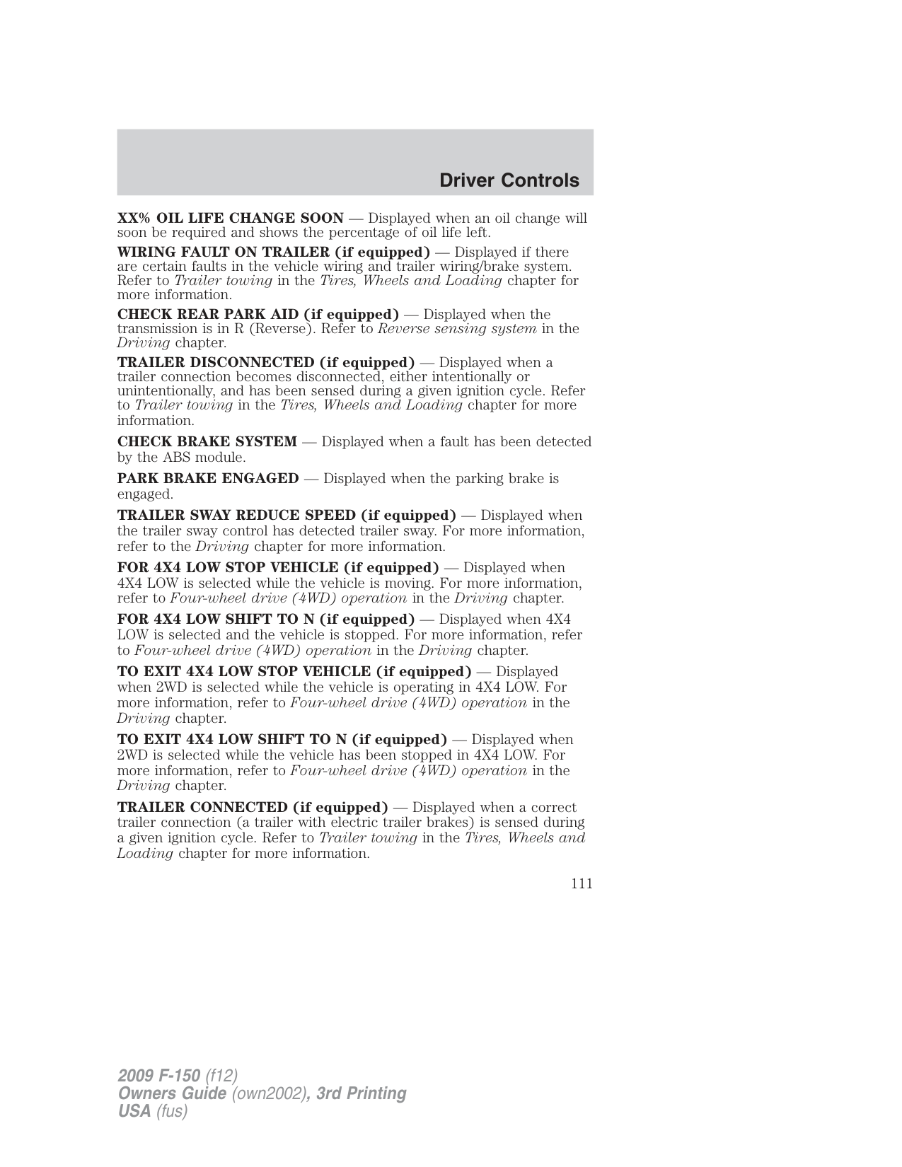
|Warning display|Status| |---|---| |Driver door ajar|The warning can return after the ignition key is turned from off to on if the condition still exists.| |Passenger door ajar|The warning can return after the ignition key is turned from off to on if the condition still exists.| |Rear left door ajar|The warning can return after the ignition key is turned from off to on if the condition still exists.| |Rear right door ajar|The warning can return after the ignition key is turned from off to on if the condition still exists.| |XXX miles to E fuel level low|The warning can be reset. If the condition/problem occurs again, the message can return after being reset. The warning can return after the ignition key is turned from off to on if the condition/problem still exists.| |Check charging system|The warning can be reset. If the condition/problem occurs again, the message can return after being reset. The warning can return after the ignition key is turned from off to on if the condition/problem still exists.| |Tire pressure sensor fault|The warning can be reset. If the condition/problem occurs again, the message can return after being reset. The warning can return after the ignition key is turned from off to on if the condition/problem still exists.| |Low tire pressure|The warning can be reset. If the condition/problem occurs again, the message can return after being reset. The warning can return after the ignition key is turned from off to on if the condition/problem still exists.| |Service RSC now|The warning can be reset. If the condition/problem occurs again, the message can return after being reset. The warning can return after the ignition key is turned from off to on if the condition/problem still exists.| |Check fuel fill inlet|The warning can be reset. If the condition/problem occurs again, the message can return after being reset. The warning can return after the ignition key is turned from off to on if the condition/problem still exists.| |Check 4x4 (if equipped)|The warning can be reset. If the condition/problem occurs again, the message can return after being reset. The warning can return after the ignition key is turned from off to on if the condition/problem still exists.| |Tire pressure monitor fault|The warning can be reset. If the condition/problem occurs again, the message can return after being reset. The warning can return after the ignition key is turned from off to on if the condition/problem still exists.|
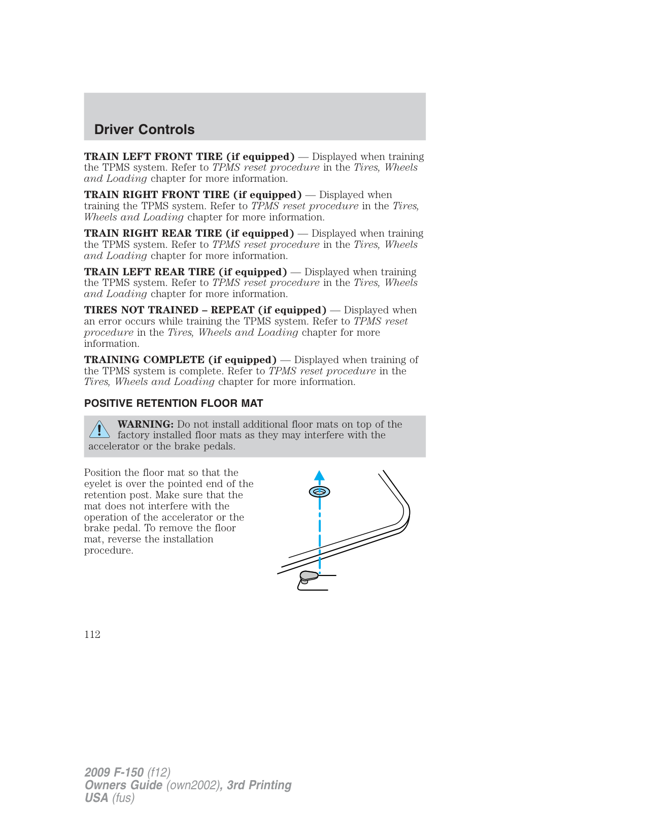
|Brake fluid level low|The warning can be reset. The warning can return after the ignition key is turned from off to on if the condition/problem still exists.| |Trailer brake module fault (if equipped)|The warning can be reset. The warning can return after the ignition key is turned from off to on if the condition/problem still exists.| |Oil change required|The warning can be reset. The warning can return after the ignition key is turned from off to on if the condition/problem still exists.| |XX% Oil life change soon|The warning can be reset. The warning can return after the ignition key is turned from off to on if the condition/problem still exists.| |Wiring fault on trailer (if equipped)|The warning can be reset. The warning can return after the ignition key is turned from off to on if the condition/problem still exists.| |Check rear park aid (if equipped)|The warning can be reset. The warning can return after the ignition key is turned from off to on if the condition/problem still exists.| |Trailer disconnected (if equipped)|The warning can be reset. The warning can return immediately after being reset if the condition/problem still exists. The warning will return 10 minutes after being reset if the condition/problem still exists. The warning can return after the ignition key is turned from off to on if the condition/problem still exists.| |Check brake system|The warning can be reset. The warning can return immediately after being reset if the condition/problem still exists. The warning will return 10 minutes after being reset if the condition/problem still exists. The warning can return after the ignition key is turned from off to on if the condition/problem still exists.|
|Warning display|Status| |---|---| |Park brake engaged|The warning can be reset. The warning can return immediately after being reset if the condition still exists. The warning will return 10 minutes after being reset if the condition/problem still exists. The warning can return after the ignition key is turned from off to on if the condition still exists.| |Trailer sway reduce speed|The warning can be reset. The warning can return immediately after being reset if the condition still exists.| |For 4x4 low stop vehicle (if equipped)|Temporary alert| |For 4x4 low shift to N (if equipped)|Temporary alert| |To exit 4x4 low stop vehicle (if equipped)|Temporary alert| |To exit 4x4 low shift to N (if equipped)|Temporary alert| |Trailer connected|Temporary alert| |Train left front tire|Temporary alert|
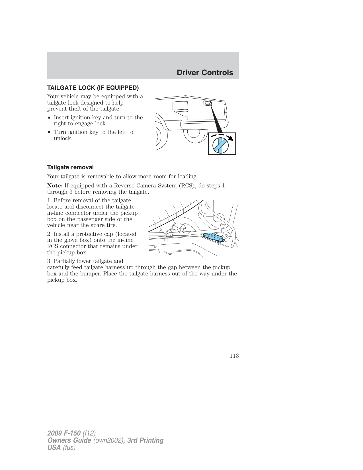
|Train right front tire|Temporary alert| |Train right rear tire|Temporary alert| |Train left rear tire|Temporary alert| |Tires not trained – repeat|Temporary alert| |Training complete|Temporary alert|
DRIVER DOOR AJAR — Displayed when the driver door is not completely closed. PASSENGER DOOR AJAR — Displayed when the passenger door is not completely closed. REAR LEFT DOOR AJAR — Displayed when the rear left door is not completely closed. REAR RIGHT DOOR AJAR — Displayed when the rear right door is not completely closed.
XXX MILES TO E FUEL LEVEL LOW — Displayed as an early reminder of a low fuel condition.
CHECK CHARGING SYSTEM — Displayed when the electrical system is not maintaining proper voltage. If you are operating electrical accessories when the engine is idling at a low speed, turn off as many of the electrical loads as soon as possible. If the warning stays on or comes on when the engine is operating at normal speeds, contact your authorized dealer as soon as possible
TIRE PRESSURE SENSOR FAULT — Displayed when a tire pressure sensor is malfunctioning, or your spare tire is in use. For more information on how the system operates under these conditions, refer to Understanding Your Tire Pressure Monitoring System (TPMS) in the Tires, Wheels and Loading chapter. If the warning stays on or continues to come on, contact your authorized dealer as soon as possible.
LOW TIRE PRESSURE — Displayed when one or more tires on your vehicle have low tire pressure. Refer to Inflating Your Tires in the Tires, Wheels and Loading chapter.
SERVICE RSC NOW — Displayed when the RSC system is not operating properly. If the warning stays on or continues to come on, contact your authorized dealer as soon as possible.
CHECK FUEL FILL INLET — Displayed when the fuel fill inlet may not be properly closed. Refer to Easy Fuel™ “no cap” fuel system in the Maintenance and Specifications chapter.
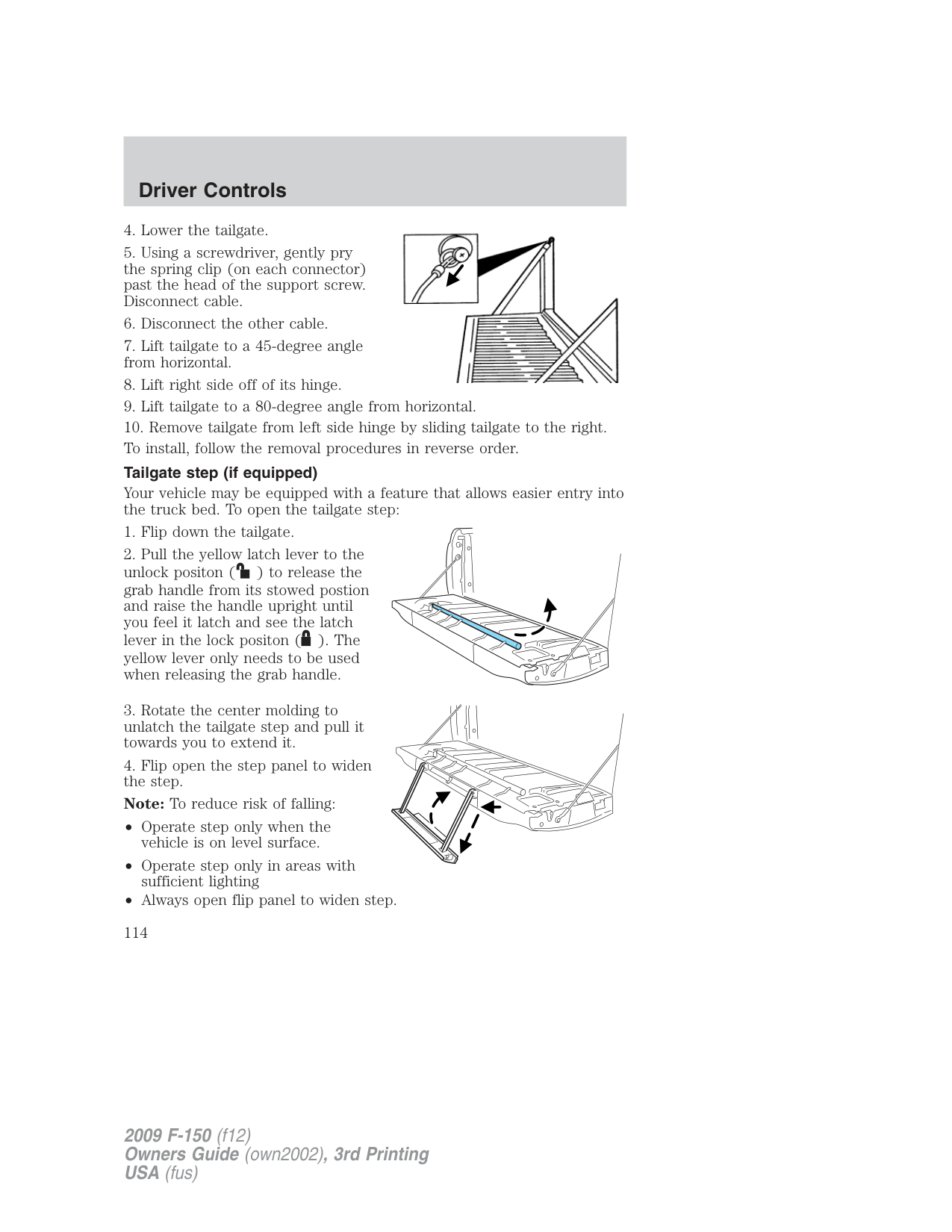
CHECK 4X4 (if equipped) — Displayed when a 4X4 system fault is present. For more information, refer to Four-wheel drive (4WD) operation in the Driving chapter.
TIRE PRESSURE MONITOR FAULT — Displayed when the Tire Pressure Monitoring System is malfunctioning. If the warning stays on or continues to come on, contact your authorized dealer as soon as possible.
BRAKE FLUID LEVEL LOW — Indicates the brake fluid level is low and the brake system should be inspected immediately. Refer to Brake fluid in the Maintenance and Specifications chapter.
TRAILER BRAKE MODULE FAULT (if equipped) — Displayed and accompanied by a single chime, in response to faults sensed by the TBC. Refer to Trailer towing in the Tires, Wheels and Loading chapter for more information.
OIL CHANGE REQUIRED — Displayed when an oil change is required.
XX% OIL LIFE CHANGE SOON — Displayed when an oil change will soon be required and shows the percentage of oil life left.
WIRING FAULT ON TRAILER (if equipped) — Displayed if there are certain faults in the vehicle wiring and trailer wiring/brake system. Refer to Trailer towing in the Tires, Wheels and Loading chapter for more information.
CHECK REAR PARK AID (if equipped) — Displayed when the transmission is in R (Reverse). Refer to Reverse sensing system in the Driving chapter.
TRAILER DISCONNECTED (if equipped) — Displayed when a trailer connection becomes disconnected, either intentionally or unintentionally, and has been sensed during a given ignition cycle. Refer to Trailer towing in the Tires, Wheels and Loading chapter for more information.
CHECK BRAKE SYSTEM — Displayed when a fault has been detected by the ABS module.
PARK BRAKE ENGAGED — Displayed when the parking brake is engaged.
TRAILER SWAY REDUCE SPEED (if equipped) — Displayed when the trailer sway control has detected trailer sway. For more information, refer to the Driving chapter for more information.
FOR 4X4 LOW STOP VEHICLE (if equipped) — Displayed when 4X4 LOW is selected while the vehicle is moving. For more information, refer to Four-wheel drive (4WD) operation in the Driving chapter.
FOR 4X4 LOW SHIFT TO N (if equipped) — Displayed when 4X4 LOW is selected and the vehicle is stopped. For more information, refer to Four-wheel drive (4WD) operation in the Driving chapter.
TO EXIT 4X4 LOW STOP VEHICLE (if equipped) — Displayed when 2WD is selected while the vehicle is operating in 4X4 LOW. For more information, refer to Four-wheel drive (4WD) operation in the Driving chapter.
TO EXIT 4X4 LOW SHIFT TO N (if equipped) — Displayed when 2WD is selected while the vehicle has been stopped in 4X4 LOW. For more information, refer to Four-wheel drive (4WD) operation in the Driving chapter.
###### TRAILER CONNECTED (if equipped) — Displayed when a correct
trailer connection (a trailer with electric trailer brakes) is sensed during a given ignition cycle. Refer to Trailer towing in the Tires, Wheels and Loading chapter for more information.
TRAIN LEFT FRONT TIRE (if equipped) — Displayed when training the TPMS system. Refer to TPMS reset procedure in the Tires, Wheels and Loading chapter for more information.
TRAIN RIGHT FRONT TIRE (if equipped) — Displayed when training the TPMS system. Refer to TPMS reset procedure in the Tires, Wheels and Loading chapter for more information.
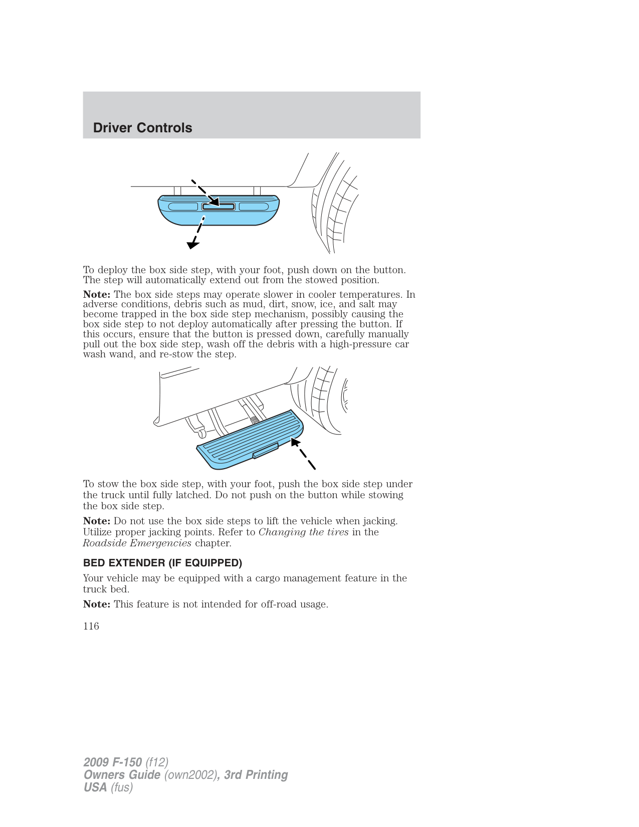
TRAIN RIGHT REAR TIRE (if equipped) — Displayed when training the TPMS system. Refer to TPMS reset procedure in the Tires, Wheels and Loading chapter for more information.
TRAIN LEFT REAR TIRE (if equipped) — Displayed when training the TPMS system. Refer to TPMS reset procedure in the Tires, Wheels and Loading chapter for more information.
TIRES NOT TRAINED – REPEAT (if equipped) — Displayed when an error occurs while training the TPMS system. Refer to TPMS reset procedure in the Tires, Wheels and Loading chapter for more information.
TRAINING COMPLETE (if equipped) — Displayed when training of the TPMS system is complete. Refer to TPMS reset procedure in the Tires, Wheels and Loading chapter for more information.
###### POSITIVE RETENTION FLOOR MAT
WARNING: Do not install additional floor mats on top of the factory installed floor mats as they may interfere with the
accelerator or the brake pedals.
Position the floor mat so that the eyelet is over the pointed end of the retention post. Make sure that the mat does not interfere with the operation of the accelerator or the brake pedal. To remove the floor mat, reverse the installation procedure.
###### TAILGATE LOCK (IF EQUIPPED)
Your vehicle may be equipped with a tailgate lock designed to help prevent theft of the tailgate.
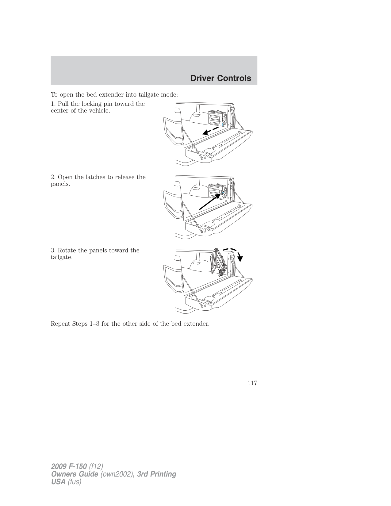
• Insert ignition key and turn to the
right to engage lock.
• Turn ignition key to the left to
unlock.
Tailgate removal Your tailgate is removable to allow more room for loading. Note: If equipped with a Reverse Camera System (RCS), do steps 1 through 3 before removing the tailgate.
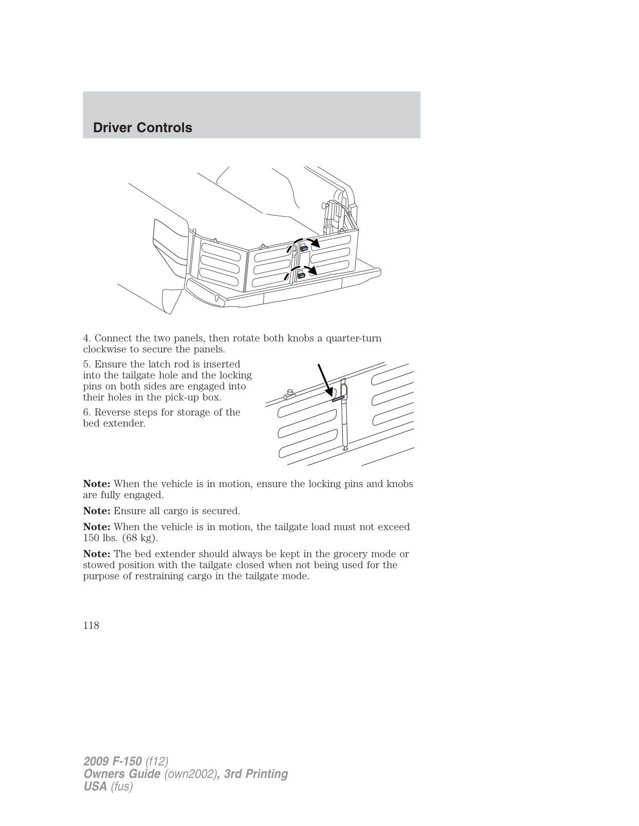

Tailgate step (if equipped) Your vehicle may be equipped with a feature that allows easier entry into the truck bed. To open the tailgate step:
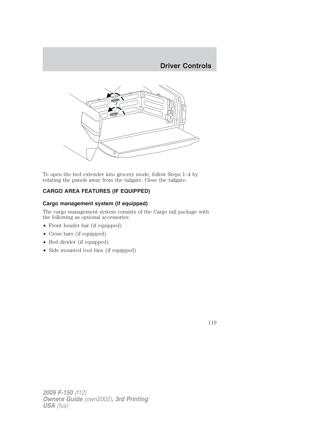
###### Box side step (if equipped)
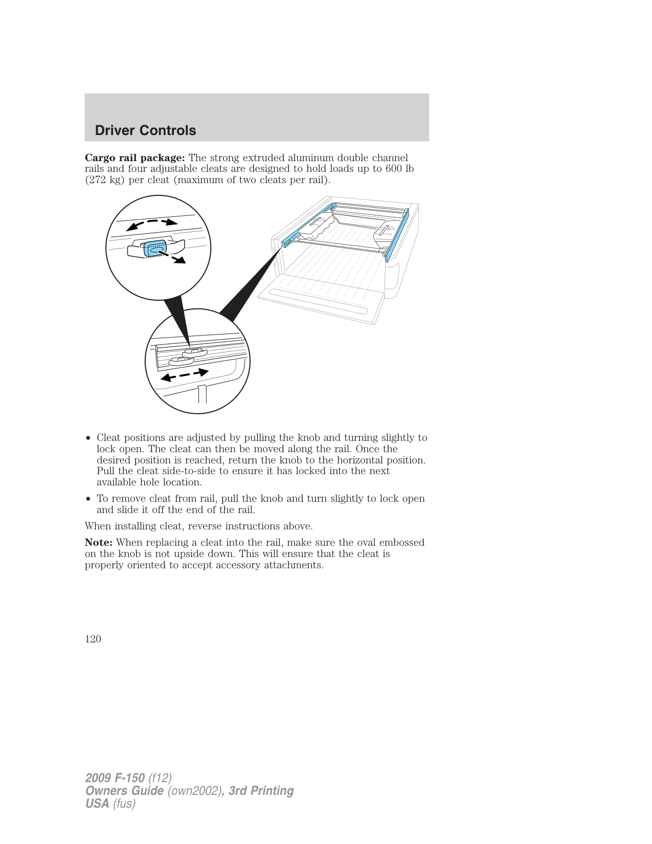
Your vehicle may be equipped with a box side step that allows easier access to the truck bed.
Note: Do not drive vehicle with box side step(s) in the deployed position.
Note: The Box Side Step load carrying capability (1 person + cargo) is 500 lbs (227 kg). Do not exceed 500 lbs (227 kg).
To deploy the box side step, with your foot, push down on the button. The step will automatically extend out from the stowed position.
Note: The box side steps may operate slower in cooler temperatures. In adverse conditions, debris such as mud, dirt, snow, ice, and salt may become trapped in the box side step mechanism, possibly causing the box side step to not deploy automatically after pressing the button. If this occurs, ensure that the button is pressed down, carefully manually pull out the box side step, wash off the debris with a high-pressure car wash wand, and re-stow the step.
To stow the box side step, with your foot, push the box side step under the truck until fully latched. Do not push on the button while stowing the box side step.
Note: Do not use the box side steps to lift the vehicle when jacking. Utilize proper jacking points. Refer to Changing the tires in the Roadside Emergencies chapter.
###### BED EXTENDER (IF EQUIPPED)
Your vehicle may be equipped with a cargo management feature in the truck bed.
Note: This feature is not intended for off-road usage.
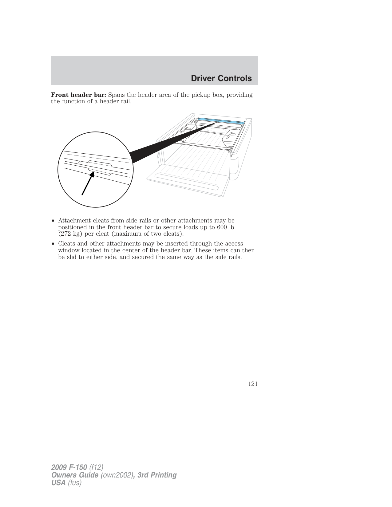
To open the bed extender into tailgate mode:
Repeat Steps 1–3 for the other side of the bed extender.
Note: When the vehicle is in motion, ensure the locking pins and knobs are fully engaged.
Note: Ensure all cargo is secured. Note: When the vehicle is in motion, the tailgate load must not exceed 150 lbs. (68 kg). Note: The bed extender should always be kept in the grocery mode or stowed position with the tailgate closed when not being used for the purpose of restraining cargo in the tailgate mode.
To open the bed extender into grocery mode, follow Steps 1–4 by rotating the panels away from the tailgate. Close the tailgate.
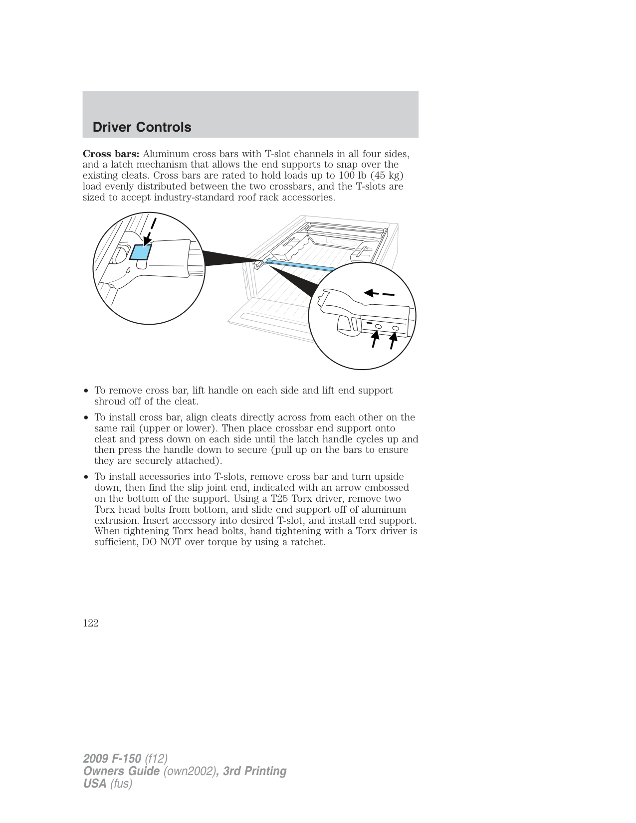
CARGO AREA FEATURES (IF EQUIPPED) Cargo management system (if equipped)
The cargo management system consists of the Cargo rail package with the following as optional accessories:
Cargo rail package: The strong extruded aluminum double channel rails and four adjustable cleats are designed to hold loads up to 600 lb (272 kg) per cleat (maximum of two cleats per rail).
When installing cleat, reverse instructions above. Note: When replacing a cleat into the rail, make sure the oval embossed on the knob is not upside down. This will ensure that the cleat is properly oriented to accept accessory attachments.
Front header bar: Spans the header area of the pickup box, providing the function of a header rail.
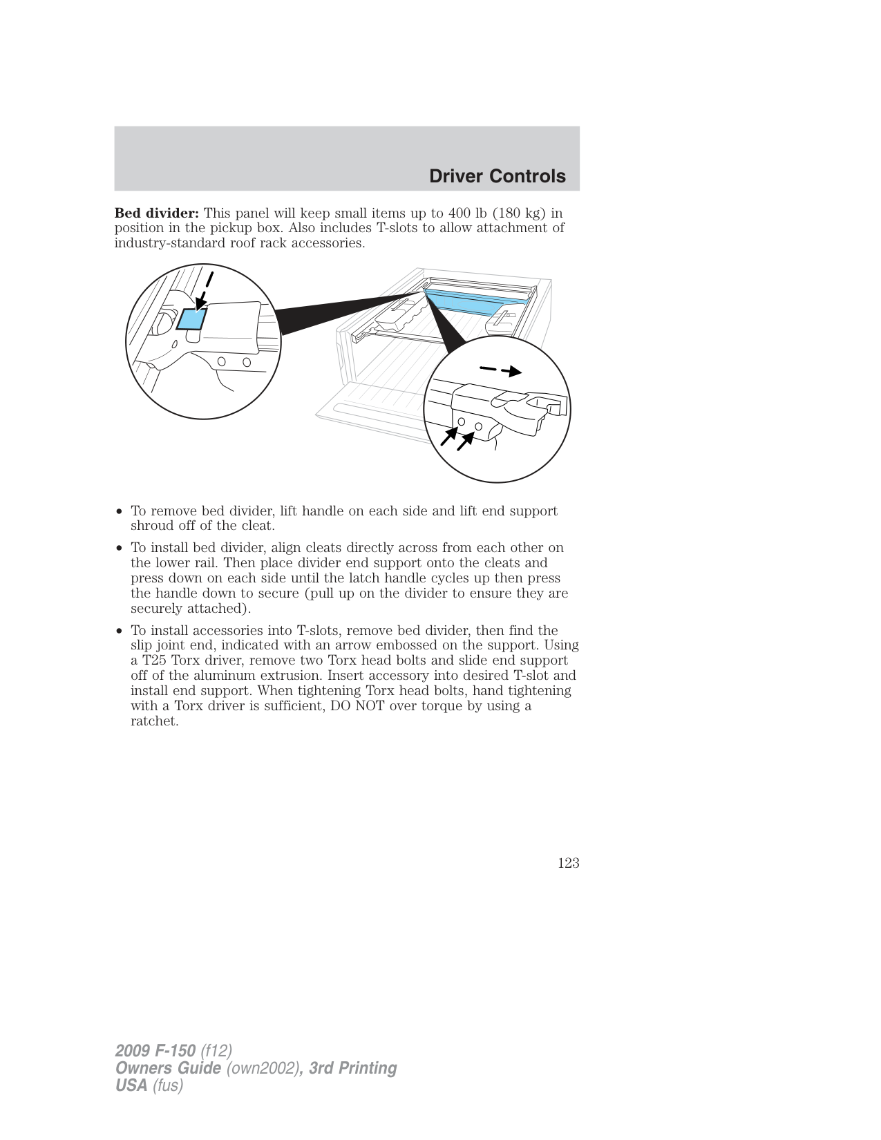
Cross bars: Aluminum cross bars with T-slot channels in all four sides, and a latch mechanism that allows the end supports to snap over the existing cleats. Cross bars are rated to hold loads up to 100 lb (45 kg) load evenly distributed between the two crossbars, and the T-slots are sized to accept industry-standard roof rack accessories.
Bed divider: This panel will keep small items up to 400 lb (180 kg) in position in the pickup box. Also includes T-slots to allow attachment of industry-standard roof rack accessories.
Side mounted tool bins: Watertight bins can be positioned at any point along the side rails and can be easily removed (even when full), and carried to wherever the contents are needed. Each bin will hold up to 60 lb (27 kg) of cargo, and has a drain plug for use as a cooler. Note: When multiple bins are placed on one side of the pickup box, the total cargo weight in all bins on that side of the pickup box cannot exceed 60 lb (27 kg).
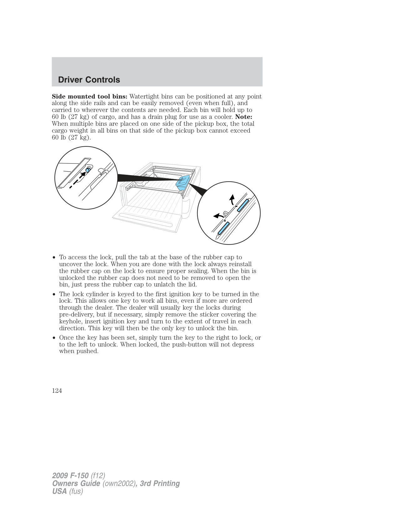
Note: Remove the bins during severe off road driving to avoid damage to the cargo bins and pickup box.
WARNING: If any levers are visible above the lid of the bin, the bin is not securely attached to the rail, and may become
detached from the vehicle if driven in that configuration.
###### KEYS
The key operates all locks on your vehicle. In case of loss, replacement keys are available from your dealer.
You should always carry a second key with you in a safe place in case you require it in an emergency.
Refer to the SecuriLock™ passive anti-theft system section in this chapter for more information.
POWER DOOR LOCKS (IF EQUIPPED) Press control to unlock all doors.
Press control to lock all doors.
###### Smart unlocking feature
The smart unlocking feature helps prevent you from locking yourself out of your vehicle.
With the key in any ignition position:
• The driver’s door will automatically unlock if it is locked by the
driver’s power lock control while the driver’s door is open.
The vehicle may still be locked with the key in the ignition, and performing one of the following actions:
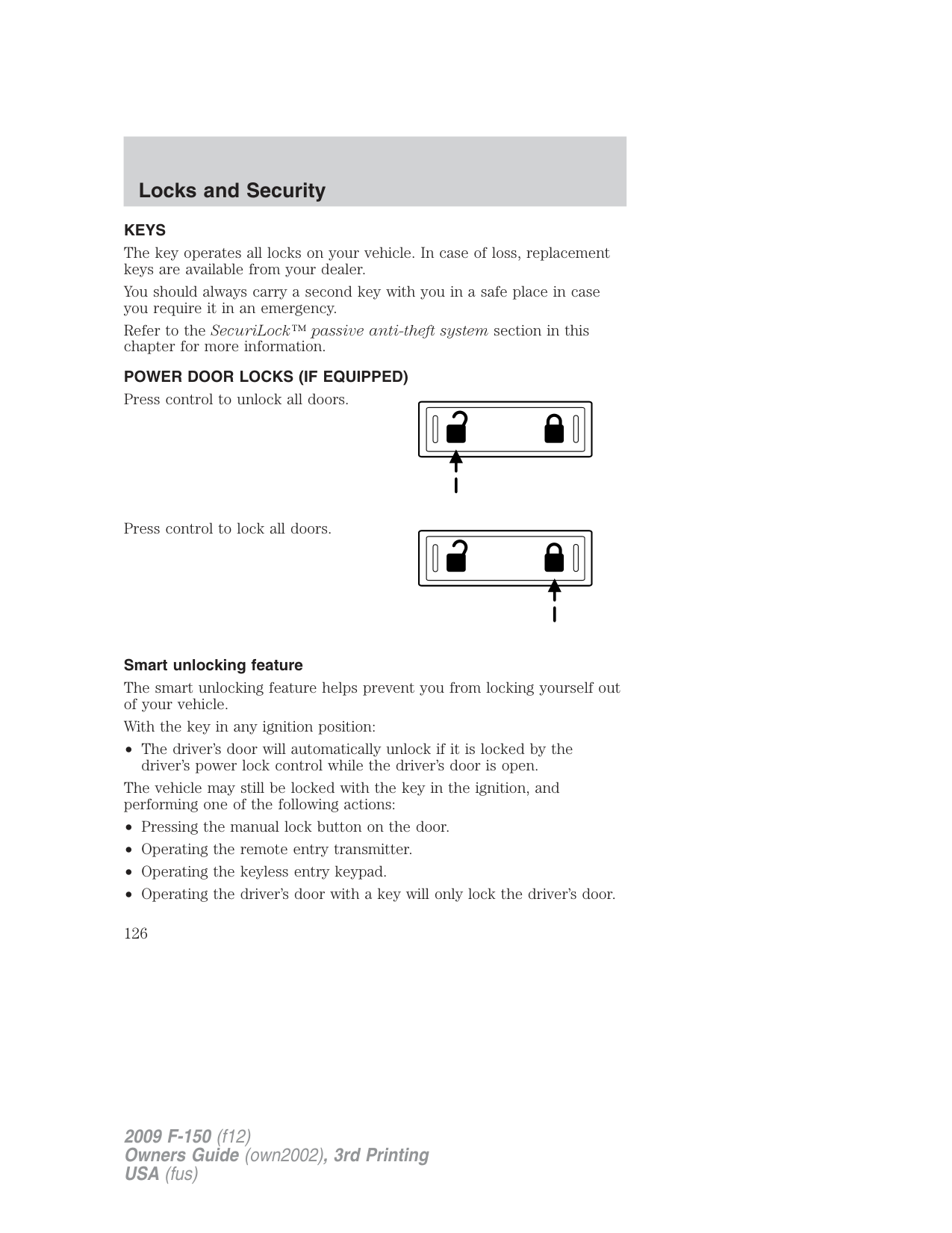
###### Autolock
The autolock feature is available on vehicles with power locking. This feature will lock all the doors when:
Your vehicle comes with the autolock feature enabled. There are four methods to enable/disable this feature:
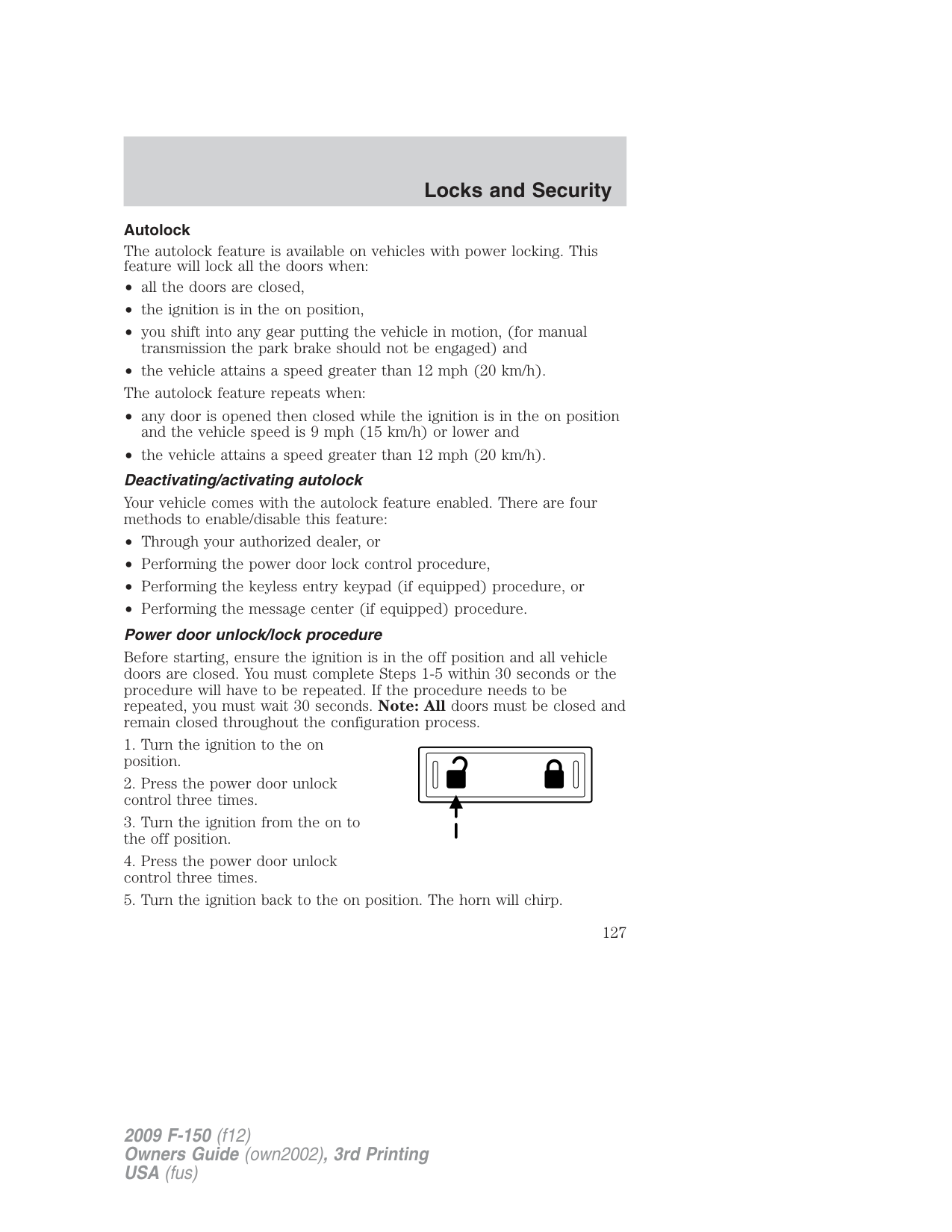
Before starting, ensure the ignition is in the off position and all vehicle doors are closed. You must complete Steps 1-5 within 30 seconds or the procedure will have to be repeated. If the procedure needs to be repeated, you must wait 30 seconds. Note: All doors must be closed and remain closed throughout the configuration process.
The user should receive a horn chirp to indicate the system has been disabled or a chirp followed by a honk to indicate the system has been enabled.
###### Message center procedure
For information regarding the activation and deactivation of the autolocks feature using the message center, refer to Message center in the Driver Controls chapter.
Autounlock feature The autounlock feature will unlock all the doors when:
Note: The doors will not autounlock if the vehicle has been electronically locked before the driver door is opened.
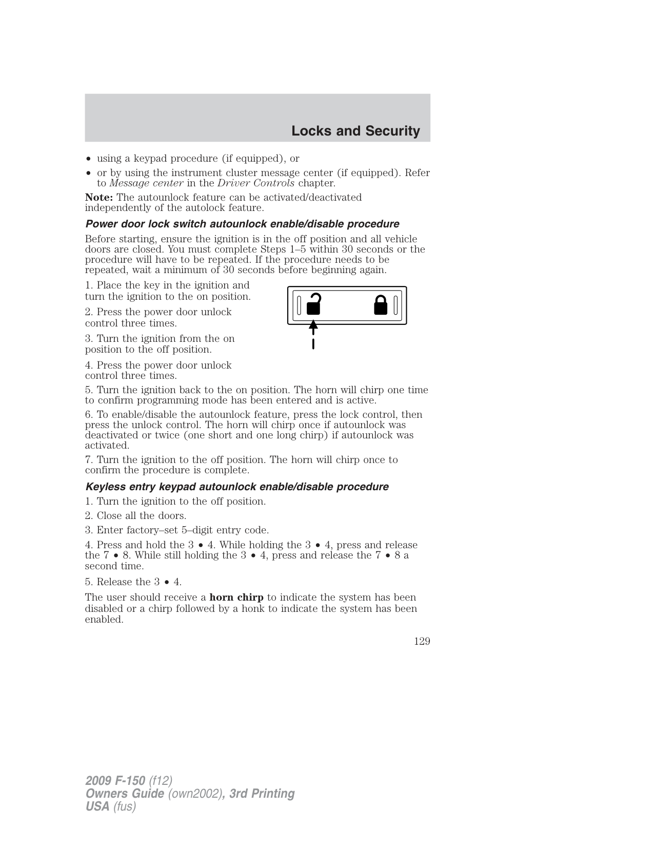
###### Deactivating/activating autounlock feature
Your vehicle comes with the autounlock features activated; there are four methods to enable/disable this feature:
Note: The autounlock feature can be activated/deactivated independently of the autolock feature.
###### Power door lock switch autounlock enable/disable procedure
Before starting, ensure the ignition is in the off position and all vehicle doors are closed. You must complete Steps 1–5 within 30 seconds or the procedure will have to be repeated. If the procedure needs to be repeated, wait a minimum of 30 seconds before beginning again.
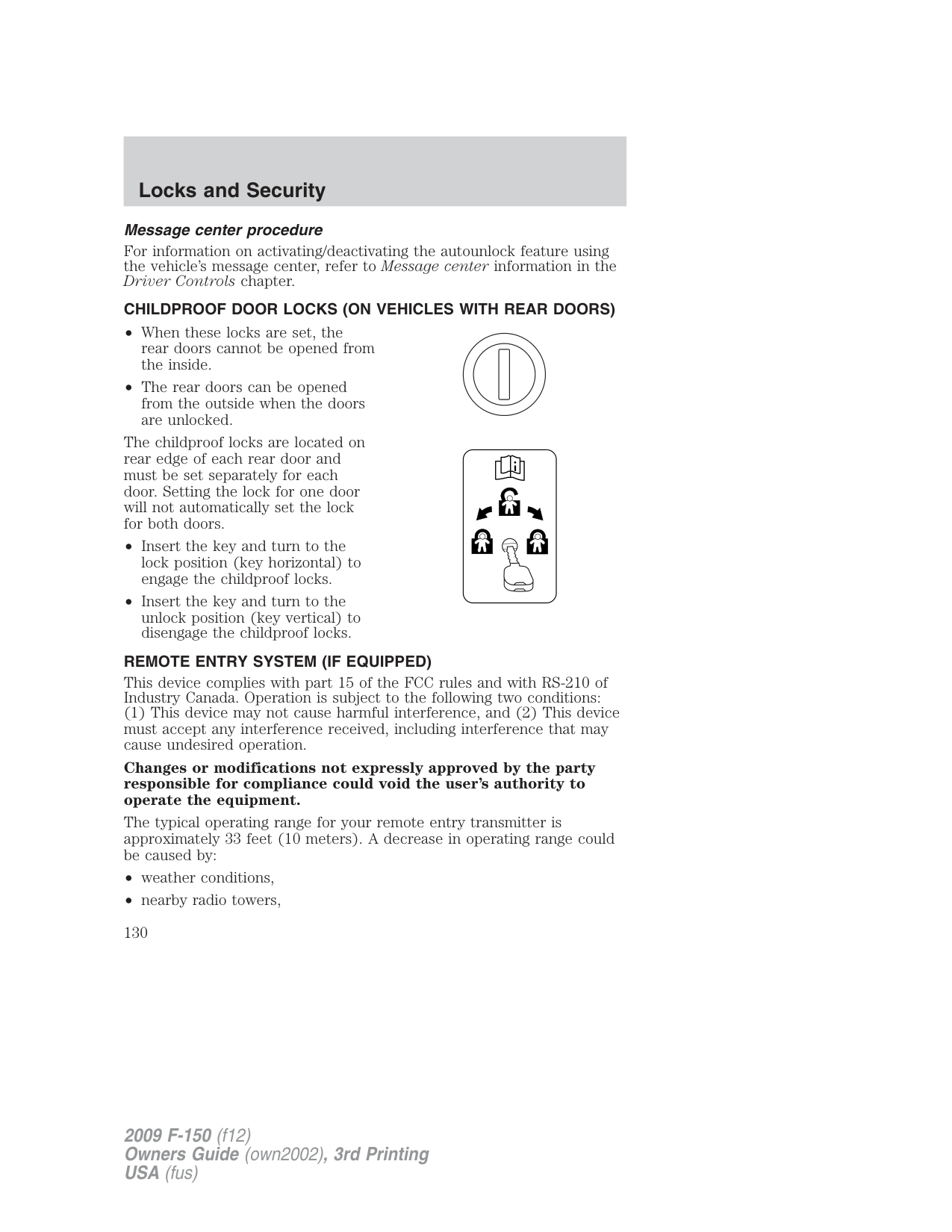
The user should receive a horn chirp to indicate the system has been disabled or a chirp followed by a honk to indicate the system has been enabled.
###### Message center procedure
For information on activating/deactivating the autounlock feature using the vehicle’s message center, refer to Message center information in the Driver Controls chapter.
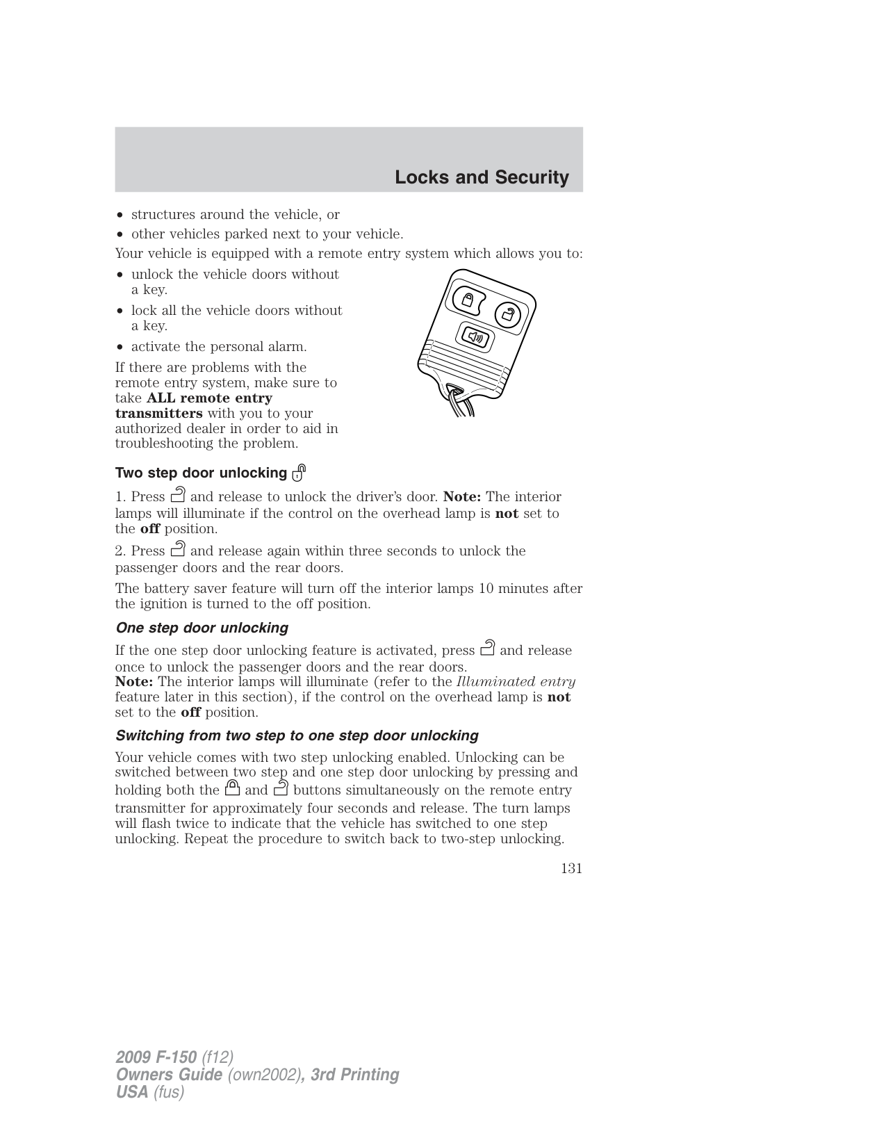
###### CHILDPROOF DOOR LOCKS (ON VEHICLES WITH REAR DOORS)
The childproof locks are located on rear edge of each rear door and must be set separately for each door. Setting the lock for one door will not automatically set the lock for both doors.
###### REMOTE ENTRY SYSTEM (IF EQUIPPED)
This device complies with part 15 of the FCC rules and with RS-210 of Industry Canada. Operation is subject to the following two conditions:
Changes or modifications not expressly approved by the party responsible for compliance could void the user’s authority to operate the equipment.
The typical operating range for your remote entry transmitter is approximately 33 feet (10 meters). A decrease in operating range could be caused by:
If there are problems with the remote entry system, make sure to take ALL remote entry transmitters with you to your authorized dealer in order to aid in troubleshooting the problem.
###### Two step door unlocking
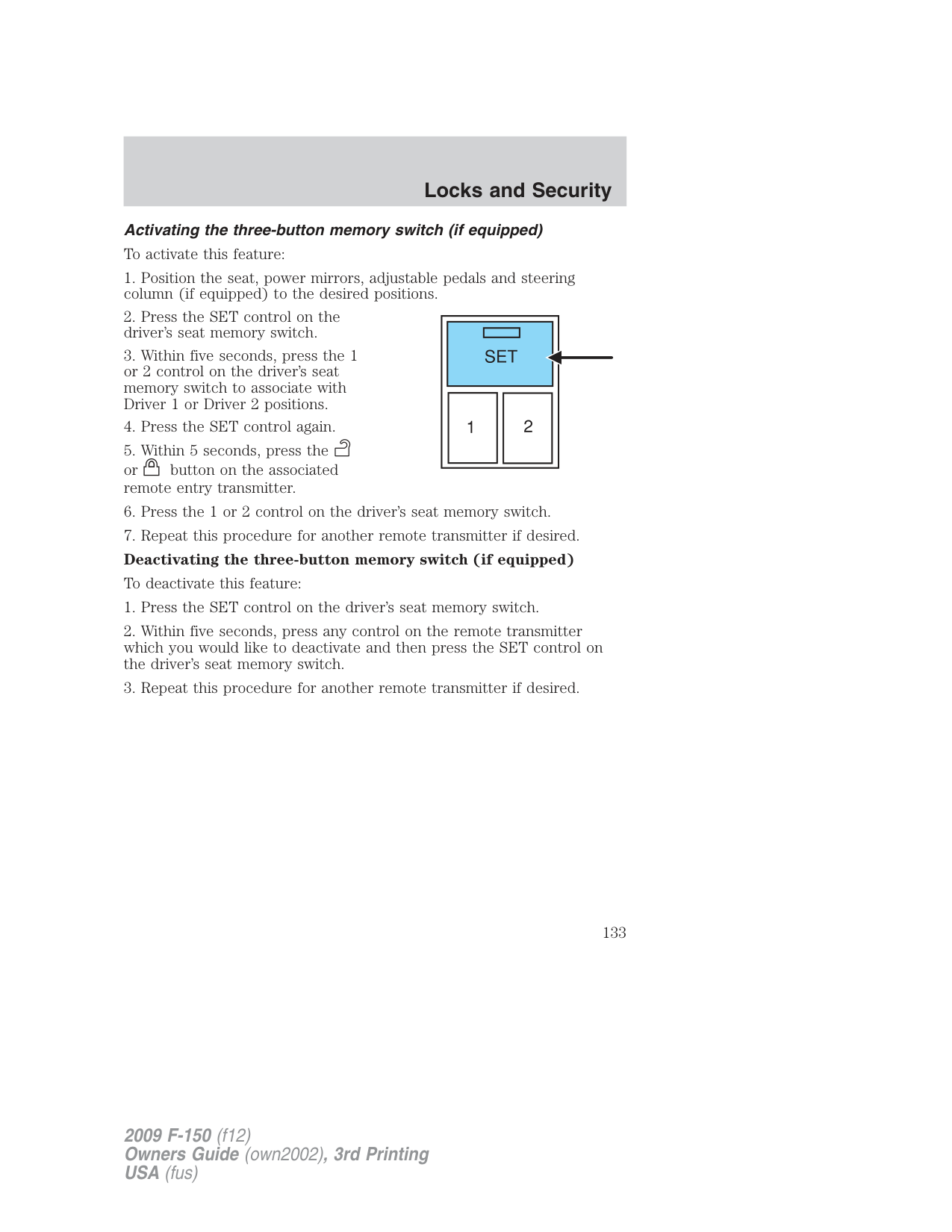
The battery saver feature will turn off the interior lamps 10 minutes after the ignition is turned to the off position.
###### One step door unlocking
If the one step door unlocking feature is activated, press and release once to unlock the passenger doors and the rear doors. Note: The interior lamps will illuminate (refer to the Illuminated entry feature later in this section), if the control on the overhead lamp is not set to the off position.
###### Switching from two step to one step door unlocking
Your vehicle comes with two step unlocking enabled. Unlocking can be switched between two step and one step door unlocking by pressing and
holding both the and buttons simultaneously on the remote entry transmitter for approximately four seconds and release. The turn lamps will flash twice to indicate that the vehicle has switched to one step unlocking. Repeat the procedure to switch back to two-step unlocking.
###### Locking the doors
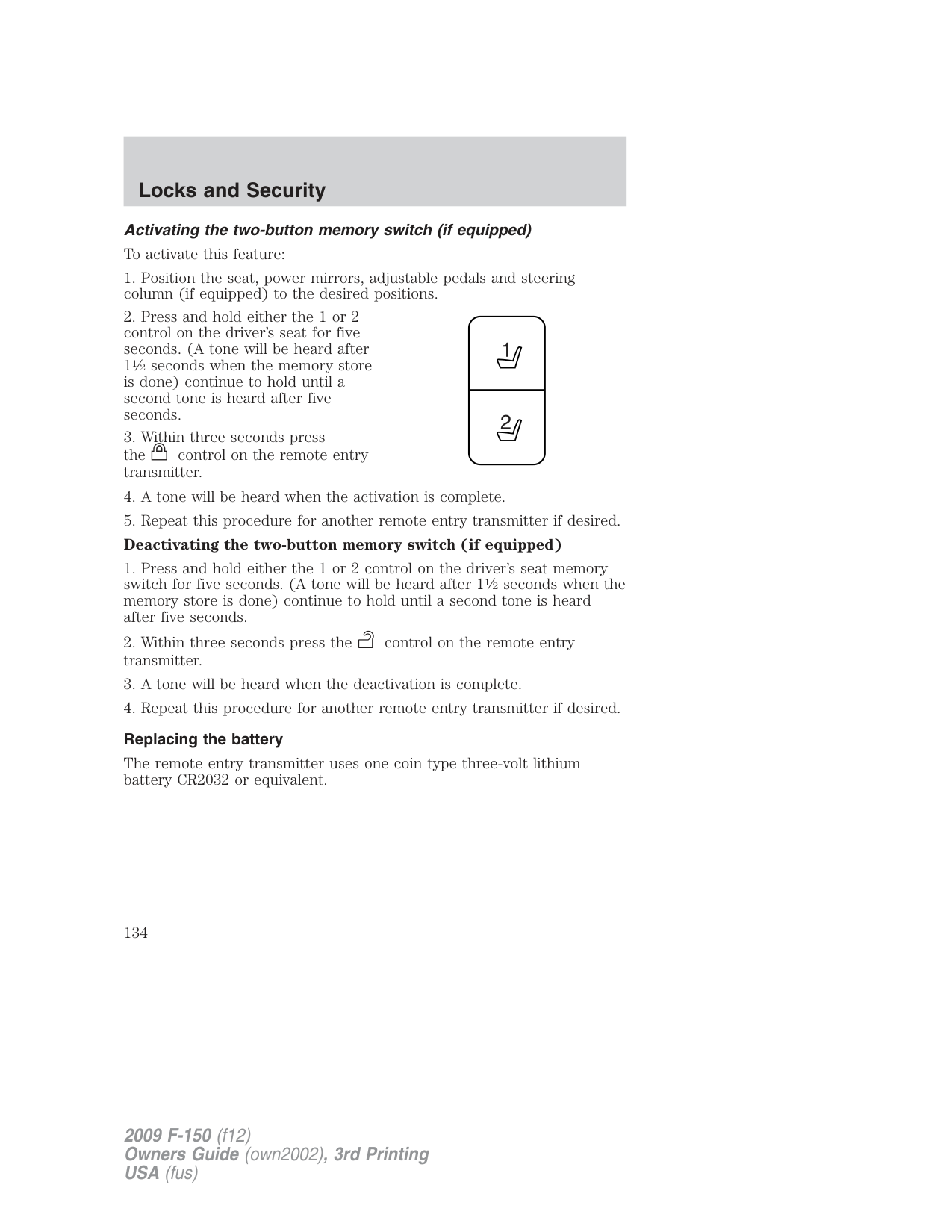
If any of the doors are not properly closed the horn will make two quick chirps and the turn signal lamps will not flash.
###### Car finder
Press twice within three seconds. The horn will chirp and the turn lamps will flash. It is recommended that this method be used to locate your vehicle, rather than using the panic alarm.
###### Sounding a panic alarm
Press to activate the alarm. Press again or turn the ignition to accessory or on to deactivate.
Note: The panic alarm will only operate when the ignition is in the off position.
Memory seats/power mirrors/adjustable pedals/steering column (if equipped)
The remote entry transmitter allows you to recall the memory seat/power mirrors/adjustable pedals/steering column (if equipped) feature.
Press to automatically move the seat, mirrors, adjustable pedals and steering column (if equipped) to the desired memory position.
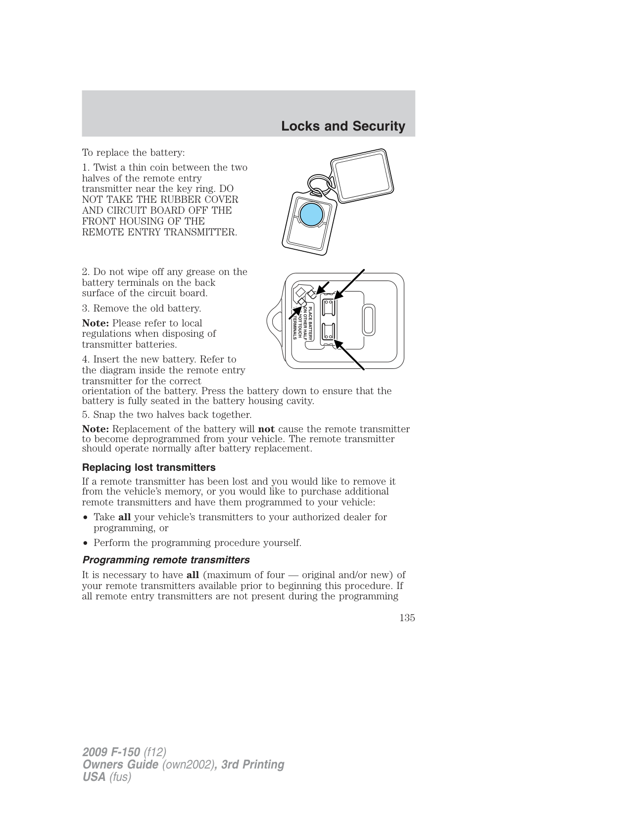
Note: The seat will not travel to its final position if the key is not in the ignition and the easy entry feature is enabled.
Activating the three-button memory switch (if equipped) To activate this feature:
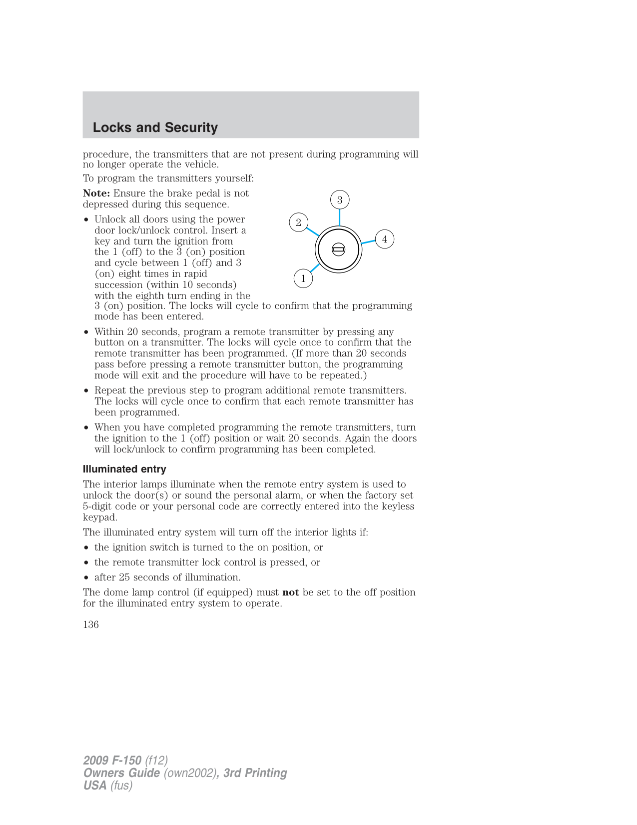
Activating the two-button memory switch (if equipped) To activate this feature:
###### Replacing the battery
The remote entry transmitter uses one coin type three-volt lithium battery CR2032 or equivalent.
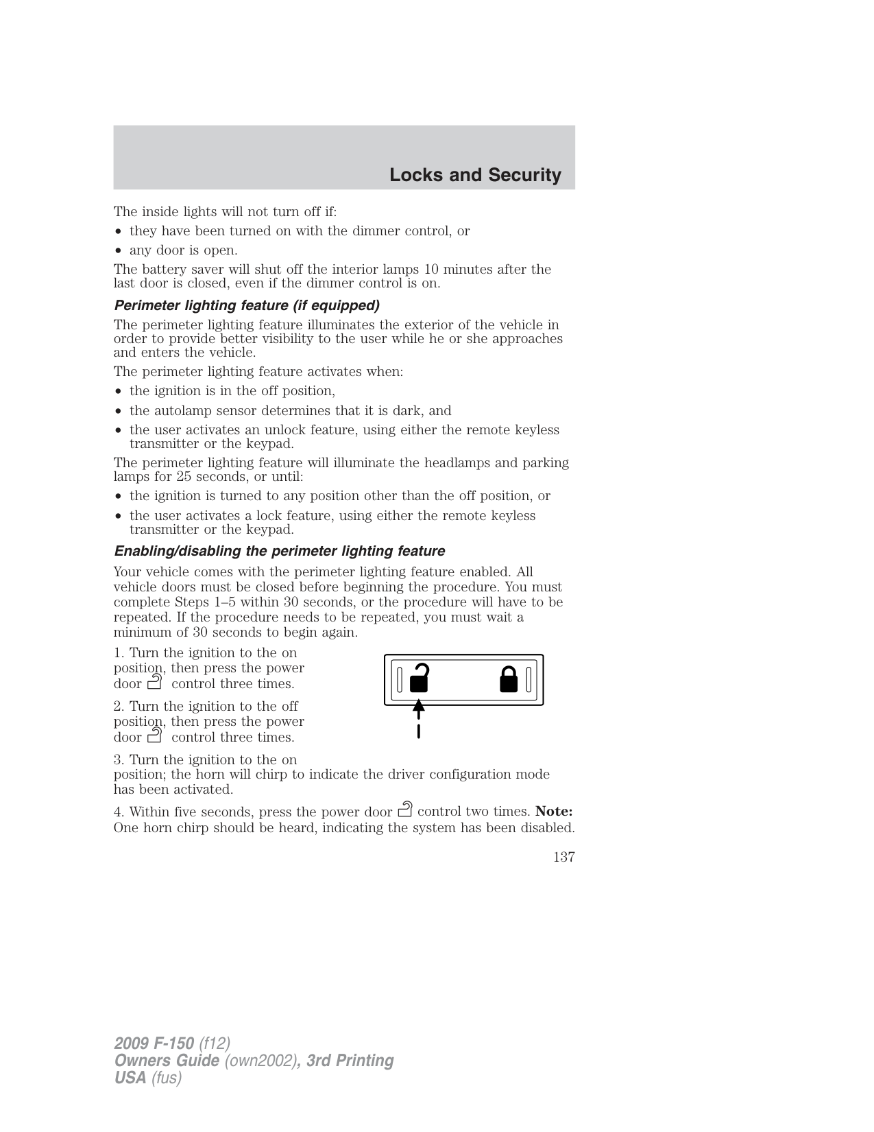
To replace the battery:
Note: Please refer to local regulations when disposing of transmitter batteries.
Note: Replacement of the battery will not cause the remote transmitter to become deprogrammed from your vehicle. The remote transmitter should operate normally after battery replacement.
Replacing lost transmitters If a remote transmitter has been lost and you would like to remove it from the vehicle’s memory, or you would like to purchase additional remote transmitters and have them programmed to your vehicle:
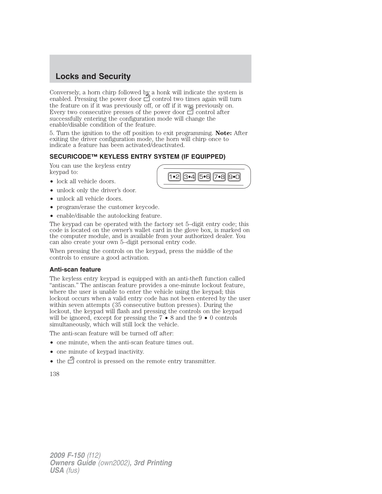
It is necessary to have all (maximum of four — original and/or new) of your remote transmitters available prior to beginning this procedure. If all remote entry transmitters are not present during the programming
procedure, the transmitters that are not present during programming will no longer operate the vehicle.
To program the transmitters yourself: Note: Ensure the brake pedal is not depressed during this sequence.
3 2
4
1
###### Illuminated entry
The interior lamps illuminate when the remote entry system is used to unlock the door(s) or sound the personal alarm, or when the factory set 5-digit code or your personal code are correctly entered into the keyless keypad.
The illuminated entry system will turn off the interior lights if:
The dome lamp control (if equipped) must not be set to the off position for the illuminated entry system to operate.
The inside lights will not turn off if:
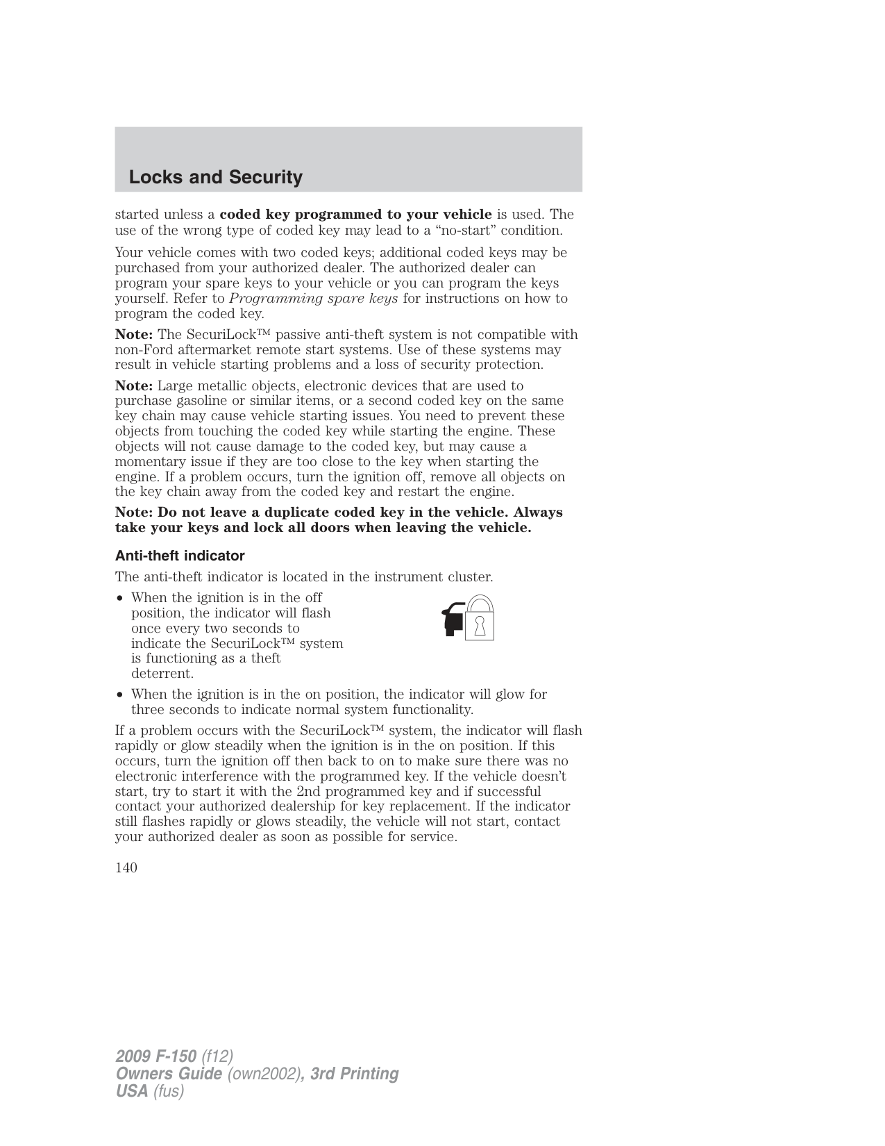
The battery saver will shut off the interior lamps 10 minutes after the last door is closed, even if the dimmer control is on.
Perimeter lighting feature (if equipped)
The perimeter lighting feature illuminates the exterior of the vehicle in order to provide better visibility to the user while he or she approaches and enters the vehicle.
The perimeter lighting feature activates when:
The perimeter lighting feature will illuminate the headlamps and parking lamps for 25 seconds, or until:
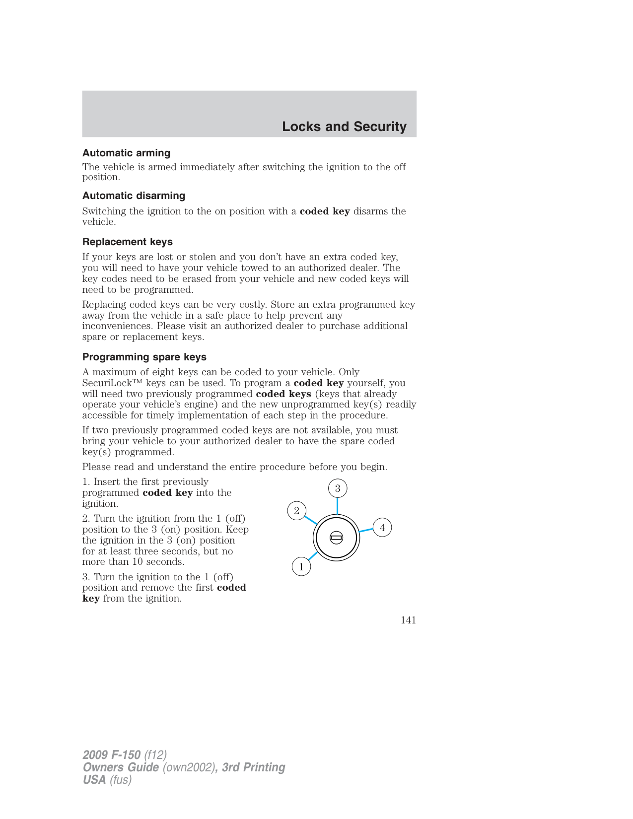
###### Enabling/disabling the perimeter lighting feature
Your vehicle comes with the perimeter lighting feature enabled. All vehicle doors must be closed before beginning the procedure. You must complete Steps 1–5 within 30 seconds, or the procedure will have to be repeated. If the procedure needs to be repeated, you must wait a minimum of 30 seconds to begin again.
###### SECURICODE™ KEYLESS ENTRY SYSTEM (IF EQUIPPED)
You can use the keyless entry keypad to:
The keypad can be operated with the factory set 5–digit entry code; this code is located on the owner’s wallet card in the glove box, is marked on the computer module, and is available from your authorized dealer. You can also create your own 5–digit personal entry code.
When pressing the controls on the keypad, press the middle of the controls to ensure a good activation.
Anti-scan feature
The keyless entry keypad is equipped with an anti-theft function called “antiscan.” The antiscan feature provides a one-minute lockout feature, where the user is unable to enter the vehicle using the keypad; this lockout occurs when a valid entry code has not been entered by the user within seven attempts (35 consecutive button presses). During the lockout, the keypad will flash and pressing the controls on the keypad will be ignored, except for pressing the 7 • 8 and the 9 • 0 controls simultaneously, which will still lock the vehicle.
The anti-scan feature will be turned off after:
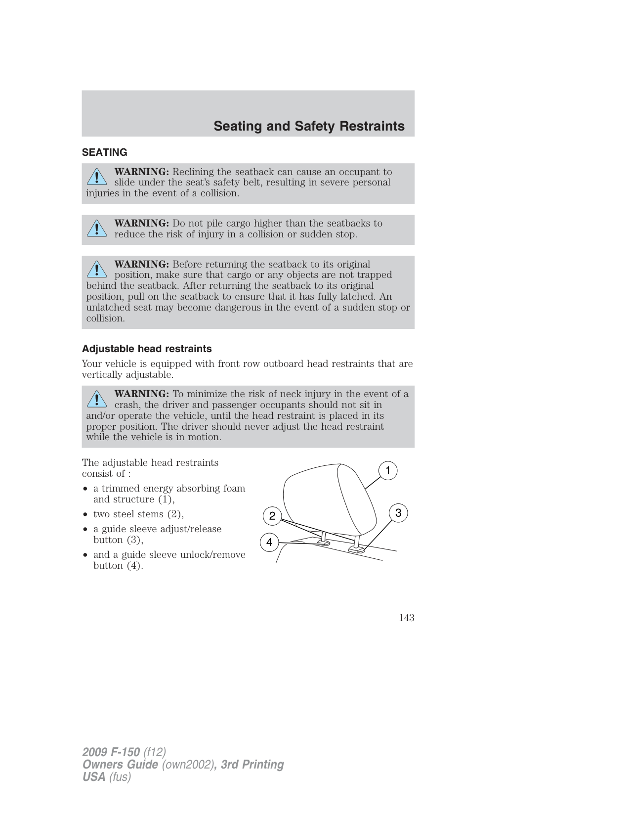
Programming a personal entry code To create your own personal entry code:
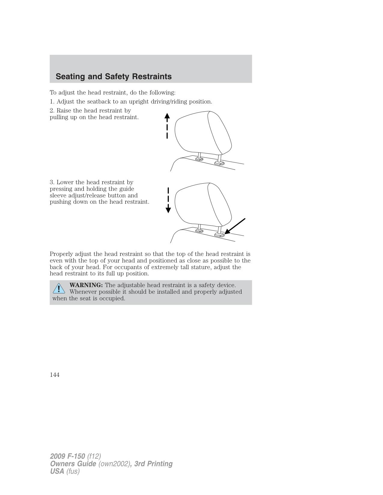
Your personal code is now erased and only the factory set 5–digit code will work.
Unlocking and locking the doors using keyless entry keypad To unlock the driver’s door, enter the factory set 5-digit code or your personal code. Each number must be pressed within five seconds of each other. Note: The driver’s door will unlock and the interior lamps will illuminate after the factory set 5-digit code or your personal code are correctly entered.
To unlock all doors, press the 3 • 4 control within five seconds. To lock all doors, press the 7 • 8 and the 9 • 0 at the same time. You do not need to enter the keypad code first. Note: The interior lamps will turn off. SECURILOCK™ PASSIVE ANTI-THEFT SYSTEM
SecuriLock™ passive anti-theft system is an engine immobilization system. This system is designed to help prevent the engine from being
started unless a coded key programmed to your vehicle is used. The use of the wrong type of coded key may lead to a “no-start” condition.
Your vehicle comes with two coded keys; additional coded keys may be purchased from your authorized dealer. The authorized dealer can program your spare keys to your vehicle or you can program the keys yourself. Refer to Programming spare keys for instructions on how to program the coded key.
Note: The SecuriLock™ passive anti-theft system is not compatible with non-Ford aftermarket remote start systems. Use of these systems may result in vehicle starting problems and a loss of security protection.
Note: Large metallic objects, electronic devices that are used to purchase gasoline or similar items, or a second coded key on the same key chain may cause vehicle starting issues. You need to prevent these objects from touching the coded key while starting the engine. These objects will not cause damage to the coded key, but may cause a momentary issue if they are too close to the key when starting the engine. If a problem occurs, turn the ignition off, remove all objects on the key chain away from the coded key and restart the engine.
Note: Do not leave a duplicate coded key in the vehicle. Always take your keys and lock all doors when leaving the vehicle.
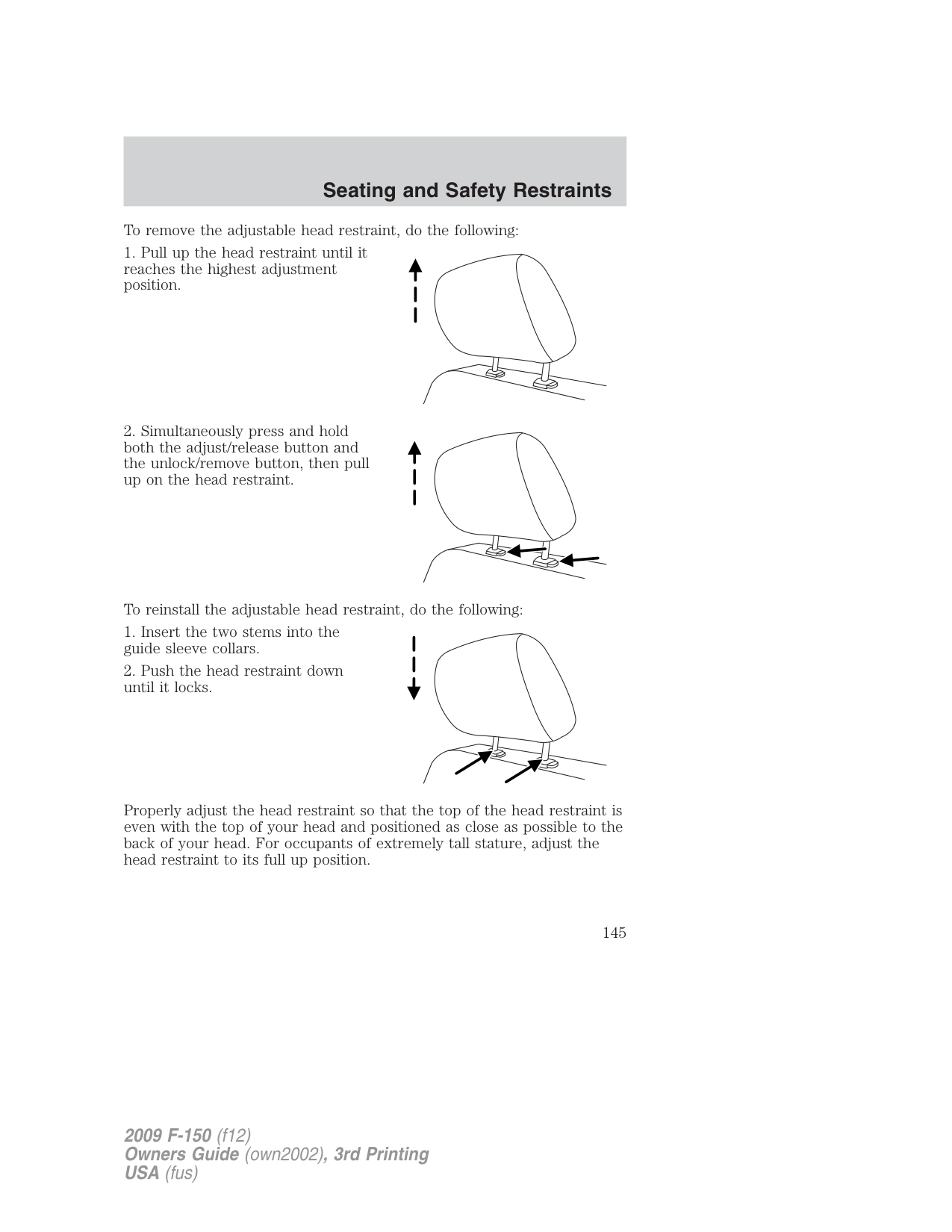
Anti-theft indicator The anti-theft indicator is located in the instrument cluster.
If a problem occurs with the SecuriLock™ system, the indicator will flash rapidly or glow steadily when the ignition is in the on position. If this occurs, turn the ignition off then back to on to make sure there was no electronic interference with the programmed key. If the vehicle doesn’t start, try to start it with the 2nd programmed key and if successful contact your authorized dealership for key replacement. If the indicator still flashes rapidly or glows steadily, the vehicle will not start, contact your authorized dealer as soon as possible for service.
###### Automatic arming
The vehicle is armed immediately after switching the ignition to the off position.
###### Automatic disarming
Switching the ignition to the on position with a coded key disarms the vehicle.
###### Replacement keys
If your keys are lost or stolen and you don’t have an extra coded key, you will need to have your vehicle towed to an authorized dealer. The key codes need to be erased from your vehicle and new coded keys will need to be programmed.
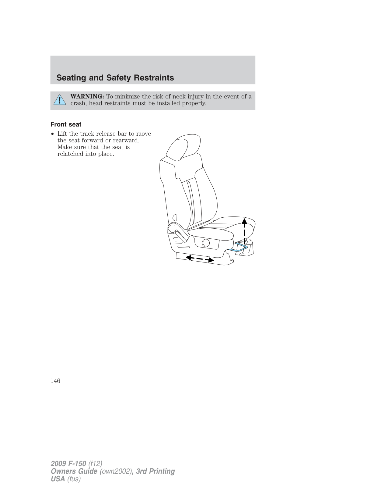
Replacing coded keys can be very costly. Store an extra programmed key away from the vehicle in a safe place to help prevent any inconveniences. Please visit an authorized dealer to purchase additional spare or replacement keys.
###### Programming spare keys
A maximum of eight keys can be coded to your vehicle. Only SecuriLock™ keys can be used. To program a coded key yourself, you will need two previously programmed coded keys (keys that already operate your vehicle’s engine) and the new unprogrammed key(s) readily accessible for timely implementation of each step in the procedure.
If two previously programmed coded keys are not available, you must bring your vehicle to your authorized dealer to have the spare coded key(s) programmed.
Please read and understand the entire procedure before you begin.
3 2
4
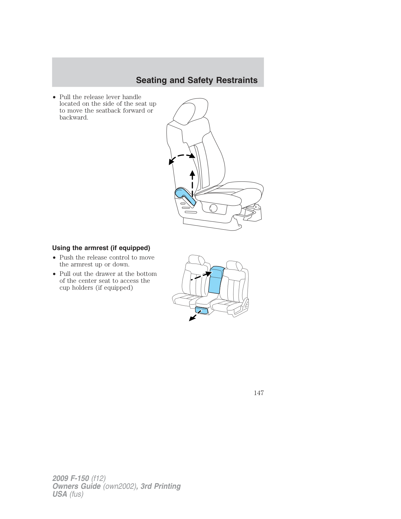
1
If successful, the new coded key(s) will start the vehicle’s engine and the theft indicator will illuminate for three seconds and then go out.
If not successful, the new coded key(s) will not start the vehicle’s engine and the theft indicator will flash on and off and you may repeat Steps 1 through 5. If failure repeats, bring your vehicle to your authorized dealer to have the new spare key(s) programmed.
###### SEATING
WARNING: Reclining the seatback can cause an occupant to slide under the seat’s safety belt, resulting in severe personal
injuries in the event of a collision.
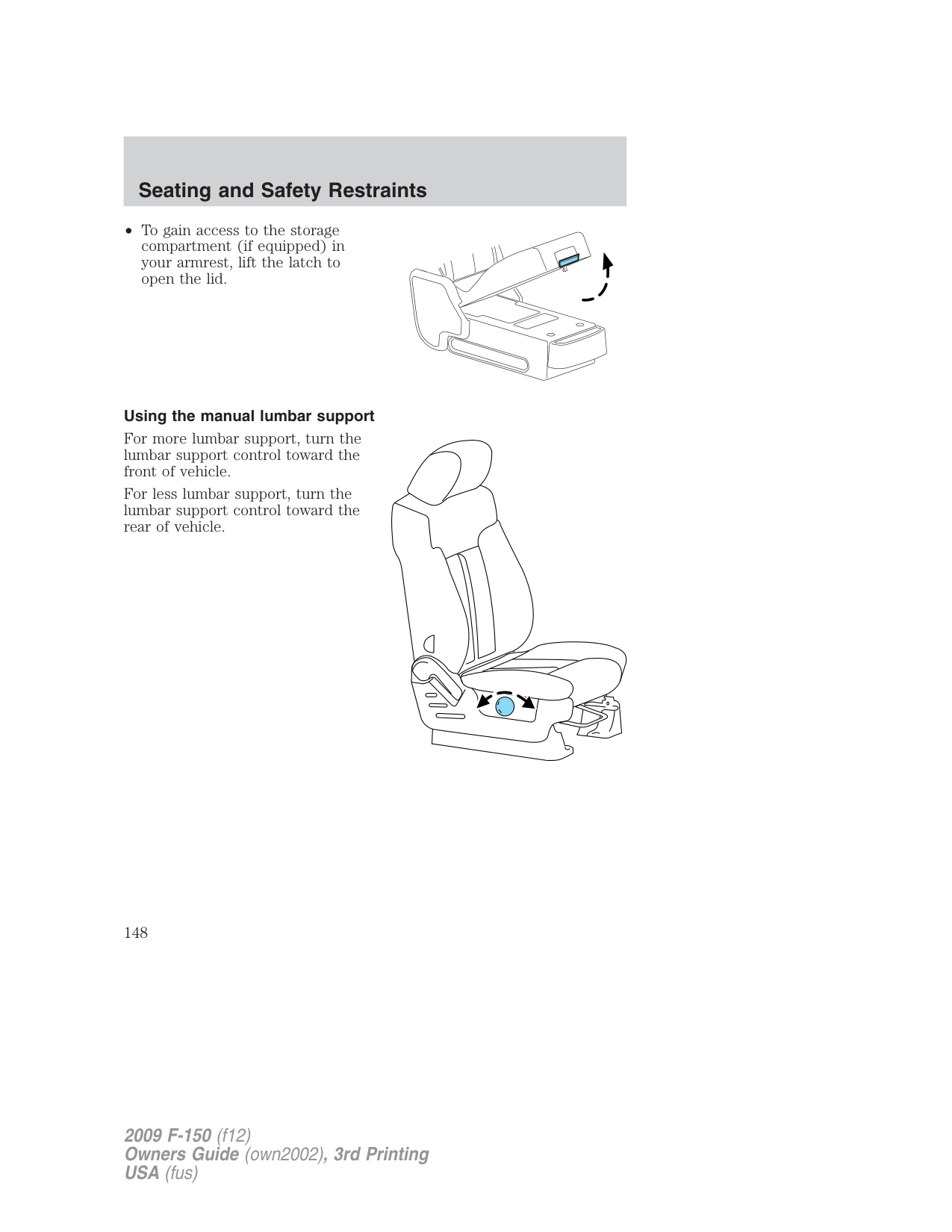
WARNING: Do not pile cargo higher than the seatbacks to reduce the risk of injury in a collision or sudden stop.
WARNING: Before returning the seatback to its original position, make sure that cargo or any objects are not trapped
behind the seatback. After returning the seatback to its original position, pull on the seatback to ensure that it has fully latched. An unlatched seat may become dangerous in the event of a sudden stop or collision.
###### Adjustable head restraints
Your vehicle is equipped with front row outboard head restraints that are vertically adjustable.
WARNING: To minimize the risk of neck injury in the event of a
crash, the driver and passenger occupants should not sit in and/or operate the vehicle, until the head restraint is placed in its proper position. The driver should never adjust the head restraint while the vehicle is in motion.
The adjustable head restraints consist of :
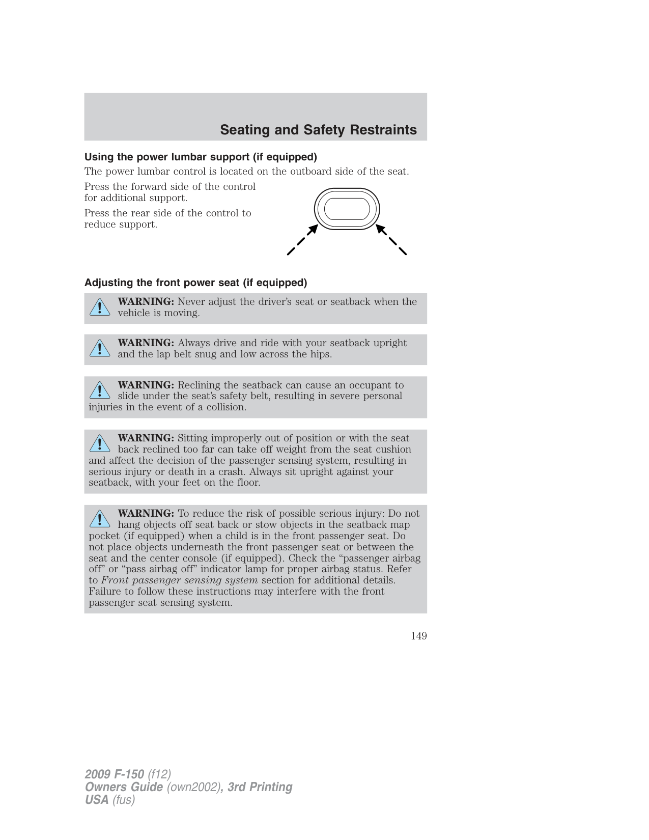
• and a guide sleeve unlock/remove
To adjust the head restraint, do the following:
Properly adjust the head restraint so that the top of the head restraint is even with the top of your head and positioned as close as possible to the back of your head. For occupants of extremely tall stature, adjust the head restraint to its full up position.
WARNING: The adjustable head restraint is a safety device. Whenever possible it should be installed and properly adjusted
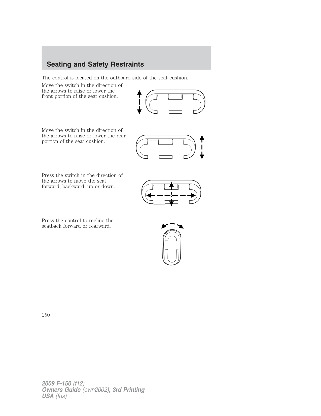
when the seat is occupied.
To remove the adjustable head restraint, do the following:
To reinstall the adjustable head restraint, do the following:
Properly adjust the head restraint so that the top of the head restraint is even with the top of your head and positioned as close as possible to the back of your head. For occupants of extremely tall stature, adjust the head restraint to its full up position.
WARNING: To minimize the risk of neck injury in the event of a crash, head restraints must be installed properly.
###### Front seat
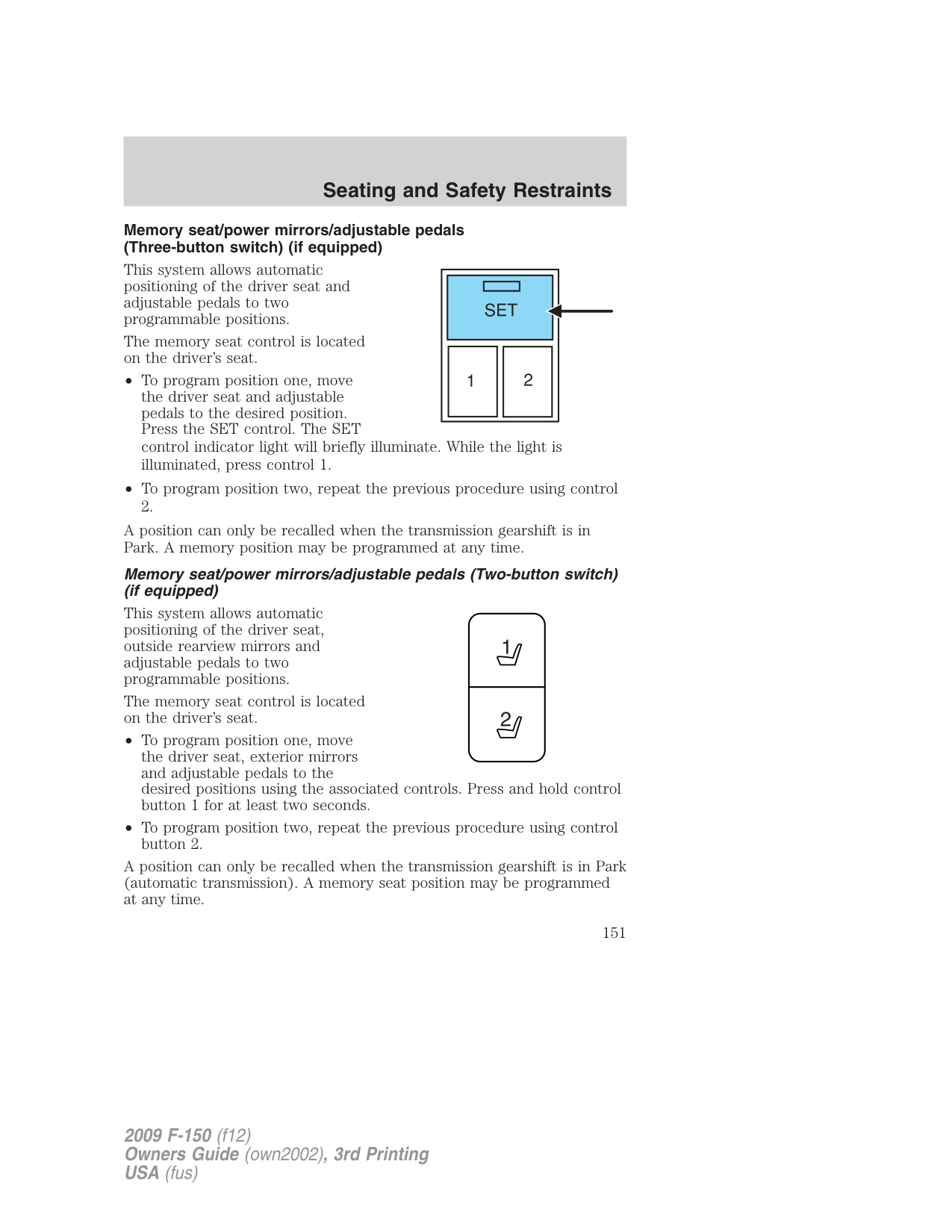
###### Using the armrest (if equipped)
###### Using the manual lumbar support
For more lumbar support, turn the lumbar support control toward the front of vehicle.
For less lumbar support, turn the lumbar support control toward the rear of vehicle.
Using the power lumbar support (if equipped) The power lumbar control is located on the outboard side of the seat. Press the forward side of the control for additional support. Press the rear side of the control to reduce support.
###### Adjusting the front power seat (if equipped)
WARNING: Never adjust the driver’s seat or seatback when the vehicle is moving.
WARNING: Always drive and ride with your seatback upright and the lap belt snug and low across the hips.
WARNING: Reclining the seatback can cause an occupant to slide under the seat’s safety belt, resulting in severe personal
injuries in the event of a collision.
WARNING: Sitting improperly out of position or with the seat back reclined too far can take off weight from the seat cushion
and affect the decision of the passenger sensing system, resulting in serious injury or death in a crash. Always sit upright against your seatback, with your feet on the floor.
WARNING: To reduce the risk of possible serious injury: Do not hang objects off seat back or stow objects in the seatback map
pocket (if equipped) when a child is in the front passenger seat. Do not place objects underneath the front passenger seat or between the seat and the center console (if equipped). Check the “passenger airbag off” or “pass airbag off” indicator lamp for proper airbag status. Refer to Front passenger sensing system section for additional details. Failure to follow these instructions may interfere with the front passenger seat sensing system.
The control is located on the outboard side of the seat cushion. Move the switch in the direction of the arrows to raise or lower the front portion of the seat cushion.
Move the switch in the direction of the arrows to raise or lower the rear portion of the seat cushion.
Press the switch in the direction of the arrows to move the seat forward, backward, up or down.
Press the control to recline the seatback forward or rearward.
Memory seat/power mirrors/adjustable pedals (Three-button switch) (if equipped)
This system allows automatic positioning of the driver seat and adjustable pedals to two programmable positions.
The memory seat control is located on the driver’s seat.
A position can only be recalled when the transmission gearshift is in Park. A memory position may be programmed at any time.
Memory seat/power mirrors/adjustable pedals (Two-button switch) (if equipped)
This system allows automatic positioning of the driver seat, outside rearview mirrors and adjustable pedals to two programmable positions.
The memory seat control is located on the driver’s seat.
A position can only be recalled when the transmission gearshift is in Park (automatic transmission). A memory seat position may be programmed at any time.
The memory seat positions are also recalled when you press your remote entry transmitter (unlock) control and the transmitter is programmed to a memory seat position or when you enter a valid customer code 1 or 2 on the keypad. To program the memory seat to remote entry transmitter, refer to Remote entry system in the Locks and Security chapter..
Note: The seat will not travel to its final position if the key is not in the ignition and the easy entry feature is enabled.
Easy-access/easy-out feature (if equipped)
The easy entry feature automatically moves the driver’s seat 2 inches (5 cm) forward when:
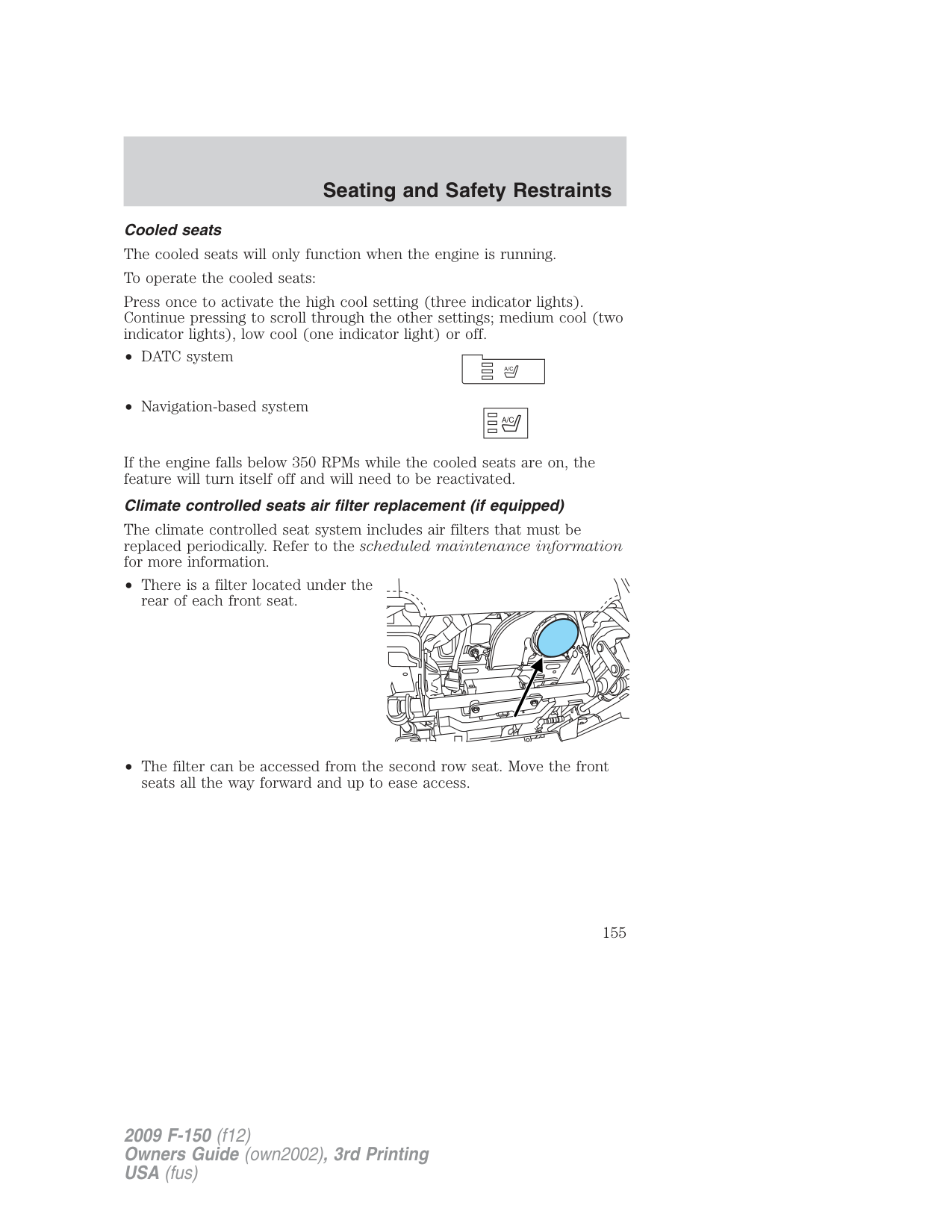
(If the seat is located less than 2 inches [5 cm] from the front of the seat track, the seat will travel up to 1⁄4 inch (.64 cm) to the front of the seat track).
The easy out feature automatically moves the driver’s seat 2 inches (5 cm) backward when:
(If the seat is located less than 2 inches (5 cm) from the rear of the seat track, the seat will travel up to 1⁄4 inch (.64 cm) to the rear of the seat track).
If the memory setting is programmed through the remote transmitter, upon unlocking the door via remote entry system, the seat position will travel to the desired memory setting less 2 inches (5 cm). Once entering the vehicle and inserting the key in the ignition while in P (Park), the easy entry feature will move the seat an additional 2 inches (5 cm) to the desired memory location. See Locks and Security for activating the memory seat feature through the remote entry system.
###### Deactivating/activating the easy access/easy out feature
The easy entry/exit feature can be turned off or on through the vehicle message center (if equipped). If your vehicle does not have a message center, the feature can be turned off or on through the following process:
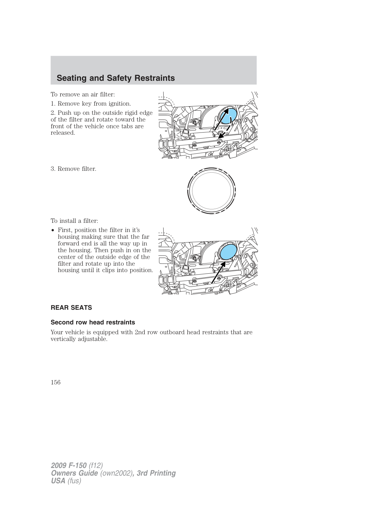
WARNING: Persons who are unable to feel pain to the skin because of advanced age, chronic illness, diabetes, spinal cord
injury, medication, alcohol use, exhaustion, or other physical conditions, must exercise care when using the seat heater. The seat heater may cause burns even at low temperatures, especially if used for long periods of time. Do not place anything on the seat that insulates against heat, such as a blanket or cushion, because this may cause the seat heater to overheat. Do not puncture the seat with pins, needles, or other pointed objects because this may damage the heating element which may cause the seat heater to overheat. An overheated seat may cause serious personal injury.
Note: Do not do the following:
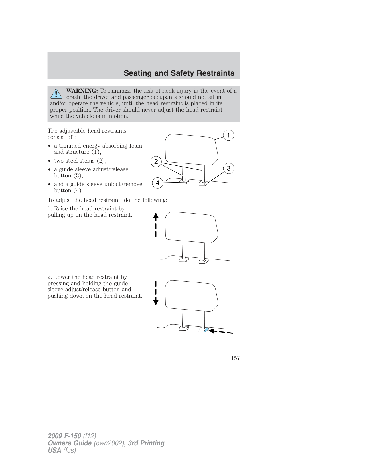
seat. Allow the seat to dry thoroughly. To operate the heated seats, do the following:
The indicator light on the control will illuminate when activated. The system automatically shuts off after 10 minutes.
###### Heated and cooled seats (if equipped)
The controls for the climate controlled seats are located on the dual electronic automatic temperature control (DEATC) system.
###### Heated seats
WARNING: Persons who are unable to feel pain to the skin because of advanced age, chronic illness, diabetes, spinal cord
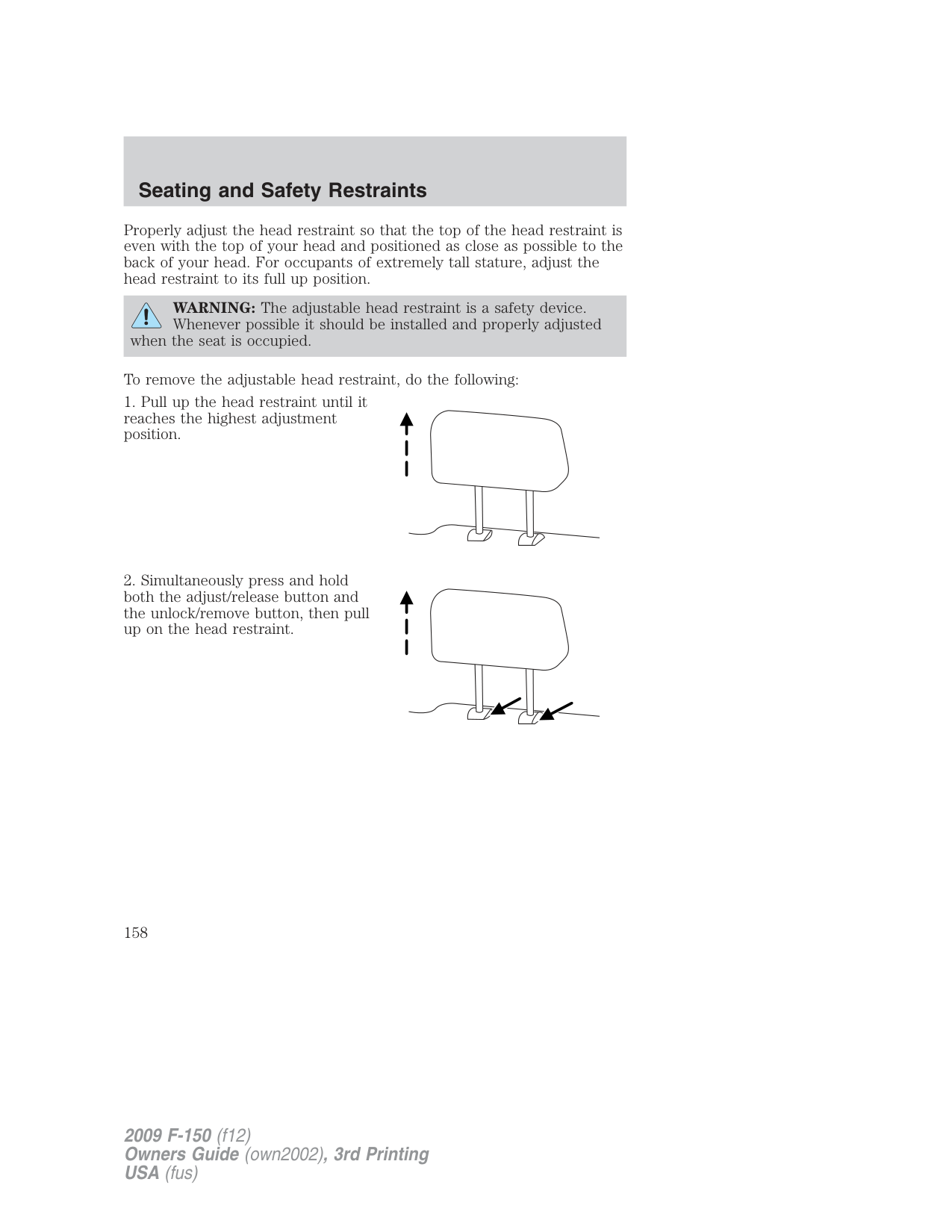
injury, medication, alcohol use, exhaustion, or other physical conditions, must exercise care when using the seat heater. The seat heater may cause burns even at low temperatures, especially if used for long periods of time. Do not place anything on the seat that insulates against heat, such as a blanket or cushion, because this may cause the seat heater to overheat. Do not puncture the seat with pins, needles, or other pointed objects because this may damage the heating element which may cause the seat heater to overheat. An overheated seat may cause serious personal injury.
Note: Do not do the following:
Cooled seats The cooled seats will only function when the engine is running. To operate the cooled seats: Press once to activate the high cool setting (three indicator lights). Continue pressing to scroll through the other settings; medium cool (two indicator lights), low cool (one indicator light) or off.
If the engine falls below 350 RPMs while the cooled seats are on, the feature will turn itself off and will need to be reactivated.
Climate controlled seats air filter replacement (if equipped)
The climate controlled seat system includes air filters that must be replaced periodically. Refer to the scheduled maintenance information for more information.
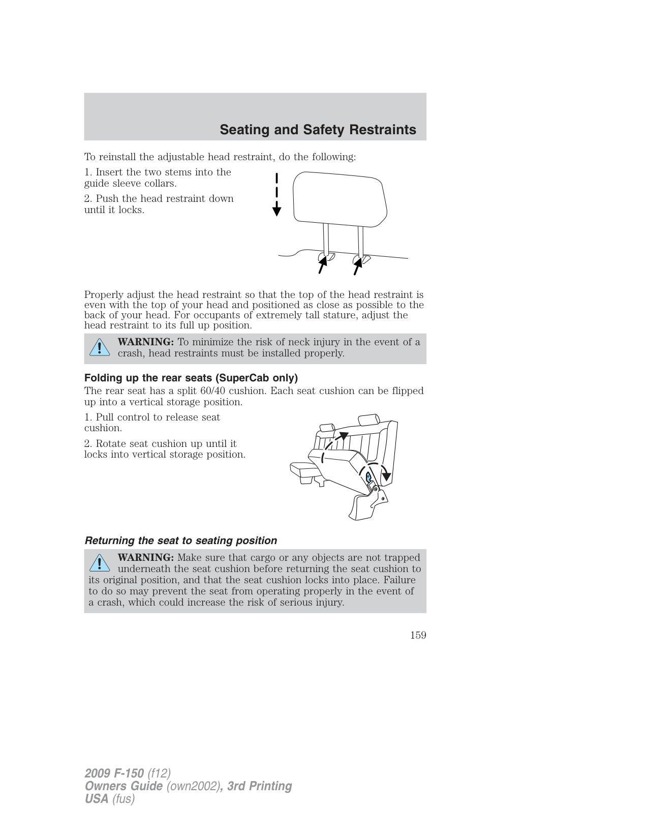
########### A/C
To remove an air filter:
To install a filter:
• First, position the filter in it’s housing making sure that the far forward end is all the way up in the housing. Then push in on the center of the outside edge of the filter and rotate up into the housing until it clips into position.
REAR SEATS Second row head restraints
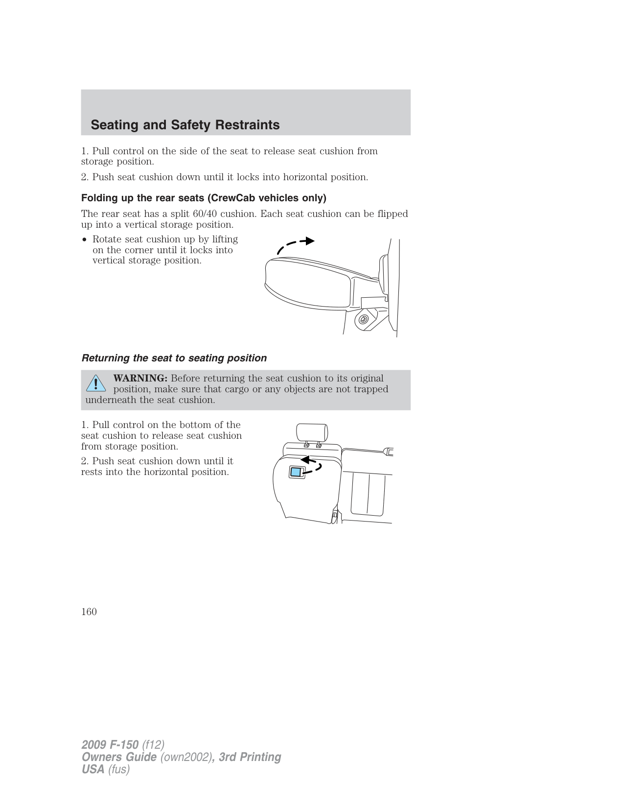
Your vehicle is equipped with 2nd row outboard head restraints that are vertically adjustable.
WARNING: To minimize the risk of neck injury in the event of a
crash, the driver and passenger occupants should not sit in and/or operate the vehicle, until the head restraint is placed in its proper position. The driver should never adjust the head restraint while the vehicle is in motion.
The adjustable head restraints consist of :
• and a guide sleeve unlock/remove
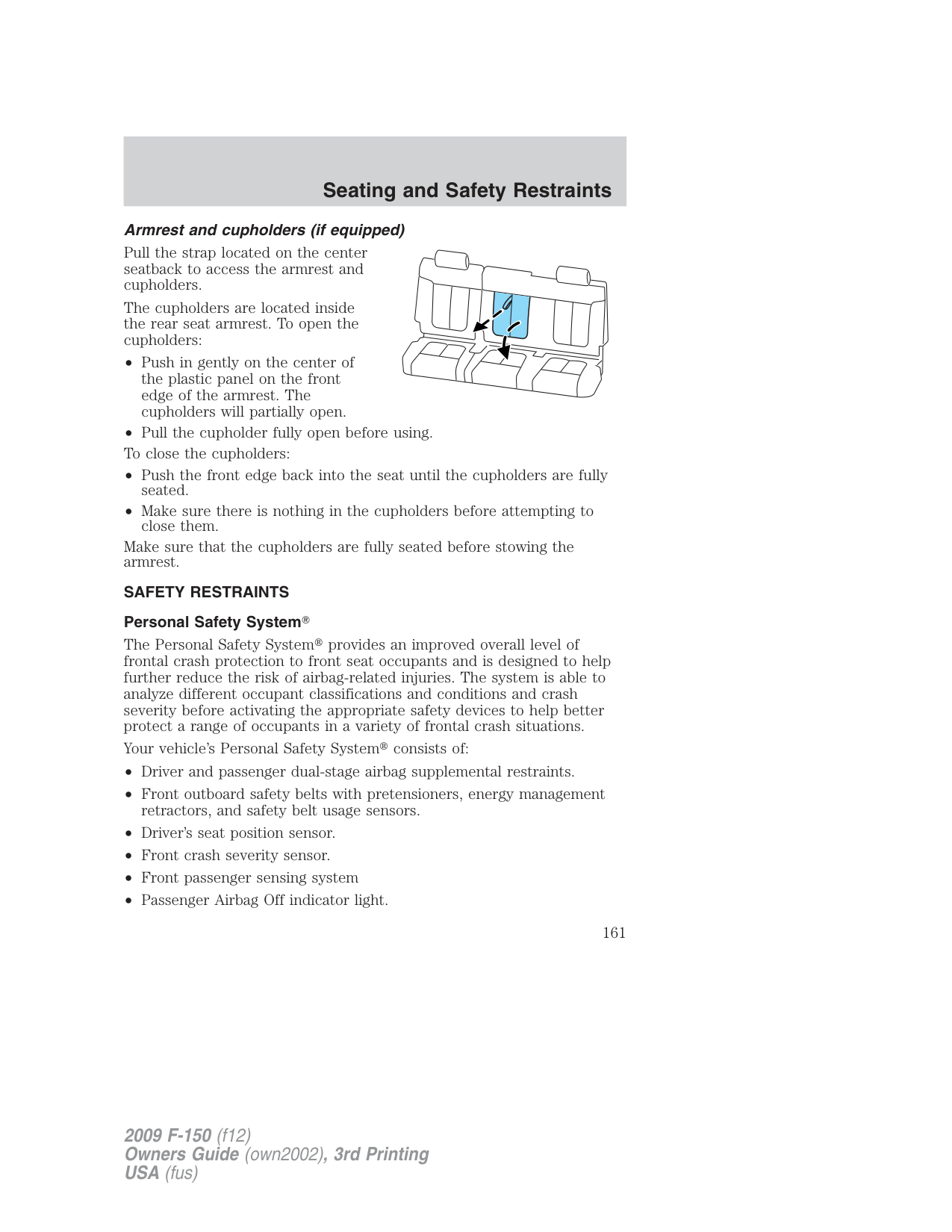
To adjust the head restraint, do the following:
Properly adjust the head restraint so that the top of the head restraint is even with the top of your head and positioned as close as possible to the back of your head. For occupants of extremely tall stature, adjust the head restraint to its full up position.
WARNING: The adjustable head restraint is a safety device. Whenever possible it should be installed and properly adjusted
when the seat is occupied.
To remove the adjustable head restraint, do the following:
To reinstall the adjustable head restraint, do the following:
Properly adjust the head restraint so that the top of the head restraint is even with the top of your head and positioned as close as possible to the back of your head. For occupants of extremely tall stature, adjust the head restraint to its full up position.
WARNING: To minimize the risk of neck injury in the event of a crash, head restraints must be installed properly.
Folding up the rear seats (SuperCab only) The rear seat has a split 60/40 cushion. Each seat cushion can be flipped up into a vertical storage position.
###### Returning the seat to seating position
WARNING: Make sure that cargo or any objects are not trapped underneath the seat cushion before returning the seat cushion to
its original position, and that the seat cushion locks into place. Failure to do so may prevent the seat from operating properly in the event of a crash, which could increase the risk of serious injury.
###### Folding up the rear seats (CrewCab vehicles only)
The rear seat has a split 60/40 cushion. Each seat cushion can be flipped up into a vertical storage position.
• Rotate seat cushion up by lifting on the corner until it locks into vertical storage position.
###### Returning the seat to seating position
WARNING: Before returning the seat cushion to its original position, make sure that cargo or any objects are not trapped
underneath the seat cushion.
###### Armrest and cupholders (if equipped)
Pull the strap located on the center seatback to access the armrest and cupholders.
The cupholders are located inside the rear seat armrest. To open the cupholders:
Make sure that the cupholders are fully seated before stowing the armrest.
SAFETY RESTRAINTS Personal Safety System
The Personal Safety System provides an improved overall level of frontal crash protection to front seat occupants and is designed to help further reduce the risk of airbag-related injuries. The system is able to analyze different occupant classifications and conditions and crash severity before activating the appropriate safety devices to help better protect a range of occupants in a variety of frontal crash situations.
Your vehicle’s Personal Safety System consists of:
###### How does the Personal Safety System work?
The Personal Safety System can adapt the deployment strategy of your vehicle’s safety devices according to crash severity and occupant classification and conditions. A collection of crash and occupant sensors provides information to the Restraints Control Module (RCM). During a crash, the RCM may activate the safety belt pretensioners and/or either none, one, or both stages of the dual-stage airbag supplemental restraints based on crash severity and occupant classification and conditions.
The fact that the pretensioners or airbags did not activate for both front seat occupants in a collision does not mean that something is wrong with the system. Rather, it means the Personal Safety System determined the accident conditions (crash severity, belt usage, etc.) were not appropriate to activate these safety devices. Front airbags are designed to activate only in frontal and near-frontal collisions, not rollovers, side-impacts, or rear-impacts unless the collision causes sufficient longitudinal deceleration.
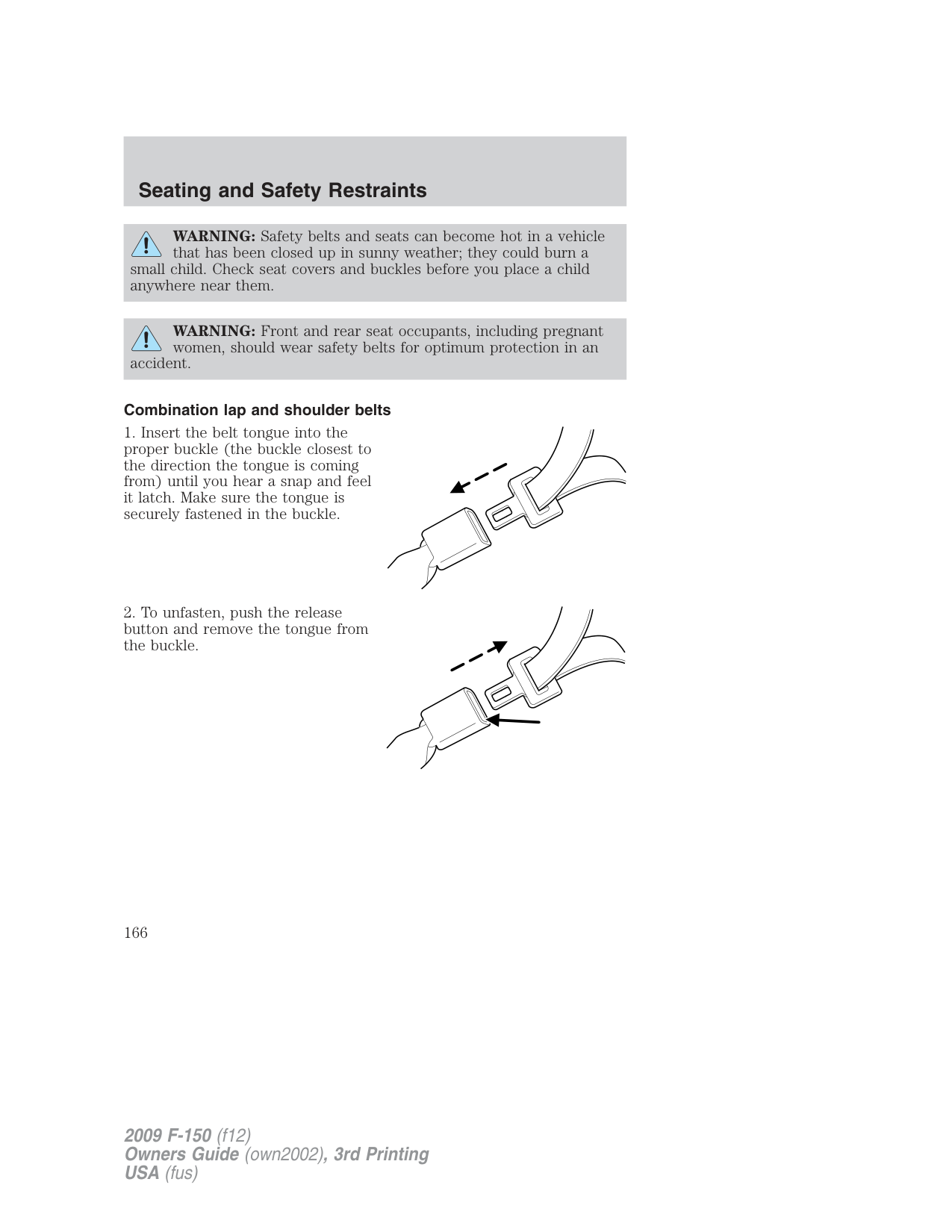
Driver and passenger dual-stage airbag supplemental restraints The dual-stage airbags offer the capability to tailor the level of airbag inflation energy. A lower, less forceful energy level is provided for more common, moderate-severity impacts. A higher energy level is used for the most severe impacts. Refer to Airbag Supplemental Restraints (SRS) section in this chapter. Front crash severity sensor
The front crash severity sensor enhances the ability to detect the severity of an impact. Positioned up front, it provides valuable information early in the crash event on the severity of the impact. This allows your Personal Safety System to distinguish between different levels of crash severity and modify the deployment strategy of the dual-stage airbags and safety belt pretensioners.
###### Driver’s seat position sensor
The driver’s seat position sensor allows your Personal Safety System to tailor the deployment level of the driver dual-stage airbag based on seat position. The system is designed to help protect smaller drivers sitting close to the driver airbag by providing a lower airbag output level.
Front passenger sensing system For airbags to do their job they must inflate with great force, and this force can pose a potentially deadly risk to occupants that are very close to the airbag when it begins to inflate. For some occupants, like infants in rear-facing child seats, this occurs because they are initially sitting very close to the airbag. For other occupants, this occurs when the occupant is not properly restrained by safety belts or child safety seats and they move forward during pre-crash braking. The most effective way to reduce the risk of unnecessary injuries is to make sure all occupants are properly restrained. Accident statistics suggest that children are much safer when properly restrained in the rear seating positions than in the front.
WARNING: Air bags can kill or injure a child in a child seat. NEVER place a rear-facing child seat in front of an active air
bag. If you must use a forward-facing child seat in the front seat, move the seat all the way back.
WARNING: Always transport children 12 years old and under in the back seat and always properly use appropriate child
restraints.
WARNING: When possible, all children 12 years old and under should be properly restrained in a rear seating position.
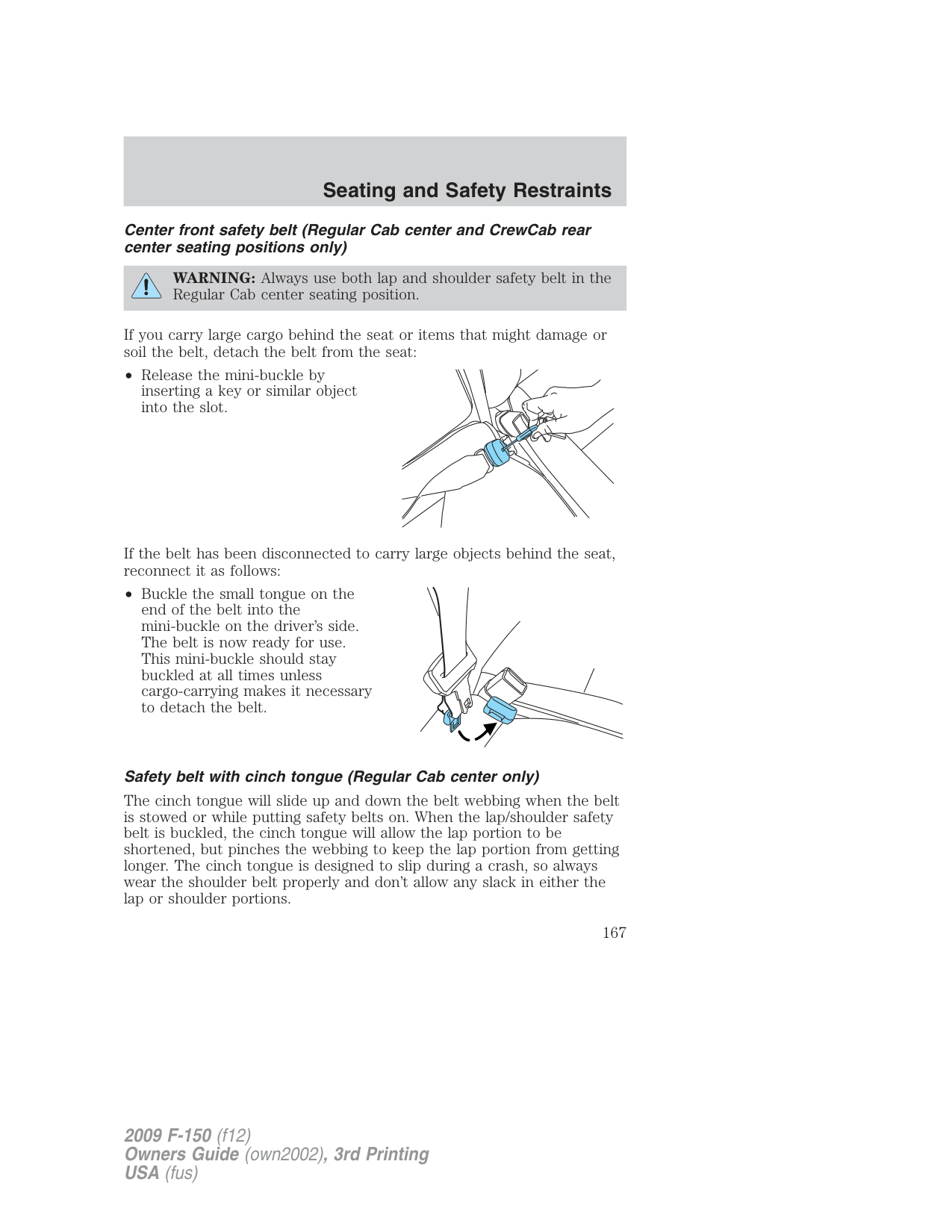
The front passenger sensing system can automatically turn off the passenger front airbag when a rear facing child seat, a forward-facing child restraint, or a booster seat is detected. Even with this technology, parents are STRONGLY encouraged to always properly restrain children in the rear seat. The sensor also turns off the passenger front airbag and passenger seat-mounted side airbag when the passenger seat is empty. When the front passenger seat is occupied and the sensing system has turned off the passenger’s frontal airbag, the “pass airbag off” indicator will light and stay lit to remind you that the front passenger frontal airbag is off. See Front passenger sensing system in the Airbag supplemental restraint system (SRS) section of this chapter. Front safety belt usage sensors
The front safety belt usage sensors detect whether or not the driver and front outboard passenger safety belts are fastened. This information
allows your Personal Safety System to tailor the airbag deployment and safety belt pretensioner activation depending upon safety belt usage. Refer to Safety belt usage sensors later in this chapter.
Front outboard safety belt pretensioners The safety belt pretensioners at the front outboard seating positions are designed to tighten the safety belts firmly against the occupant’s body during frontal collisions, and in side collisions and rollovers. This helps increase the effectiveness of the safety belts. In frontal collisions, the safety belt pretensioners can be activated alone or, if the collision is of sufficient severity, together with the front airbags. Front outboard safety belt energy management retractors
The front outboard safety belt energy management retractors allow webbing to be pulled out of the retractor in a gradual and controlled manner in response to the occupant’s forward momentum. This helps reduce the risk of force-related injuries to the occupant’s chest by limiting the load on the occupant. Refer to Energy management retractors section in this chapter.
###### Determining if the Personal Safety System is operational
The Personal Safety System uses a warning light in the instrument cluster or a back-up tone to indicate the condition of the system. Refer to the Warning lights and chimes section in the Instrument Cluster chapter. Routine maintenance of the Personal Safety System is not required.
The Restraints Control Module (RCM) monitors its own internal circuits and the circuits for the airbag supplemental restraints, crash sensor(s), safety belt pretensioners, front safety belt buckle sensors, and the driver seat position sensor. In addition, the RCM also monitors the restraints warning light in the instrument cluster. A difficulty with the system is indicated by one or more of the following.
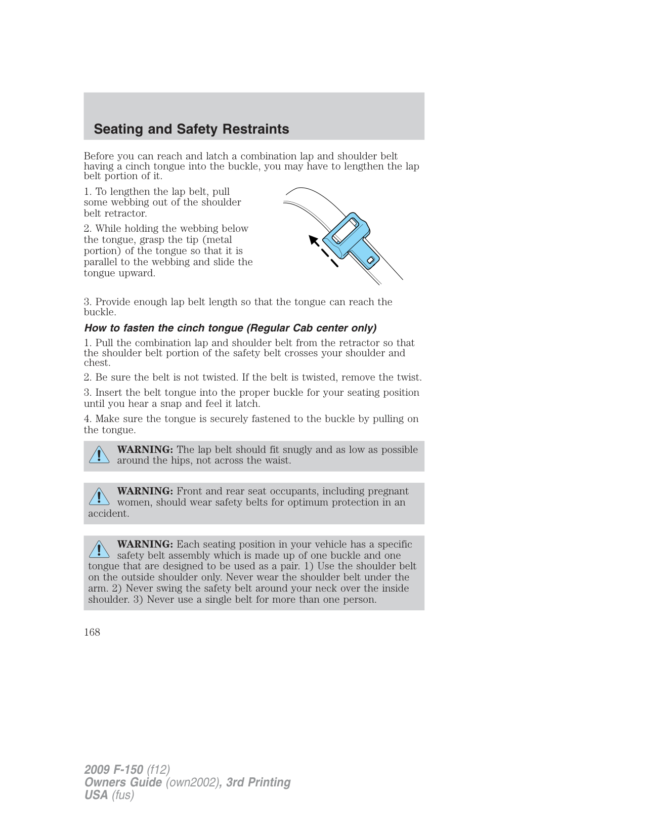
If any of these things happen, even intermittently, have the Personal Safety System serviced at an authorized dealer immediately. Unless serviced, the system may not function properly in the event of a collision.
###### Safety restraints precautions
WARNING: Always drive and ride with your seatback upright and the lap belt snug and low across the hips.
WARNING: To reduce the risk of injury, make sure children sit in a rear seating position where they can be properly restrained.
WARNING: Never let a passenger hold a child on his or her lap while the vehicle is moving. The passenger cannot protect the
child from injury in a collision.
WARNING: All occupants of the vehicle, including the driver, should always properly wear their safety belts, even when an
airbag supplemental restraint system (SRS) is provided.
WARNING: It is extremely dangerous to ride in a cargo area, inside or outside of a vehicle. In a collision, people riding in
these areas are more likely to be seriously injured or killed. Do not allow people to ride in any area of your vehicle that is not equipped with seats and safety belts. Be sure everyone in your vehicle is in a seat and using a safety belt properly.
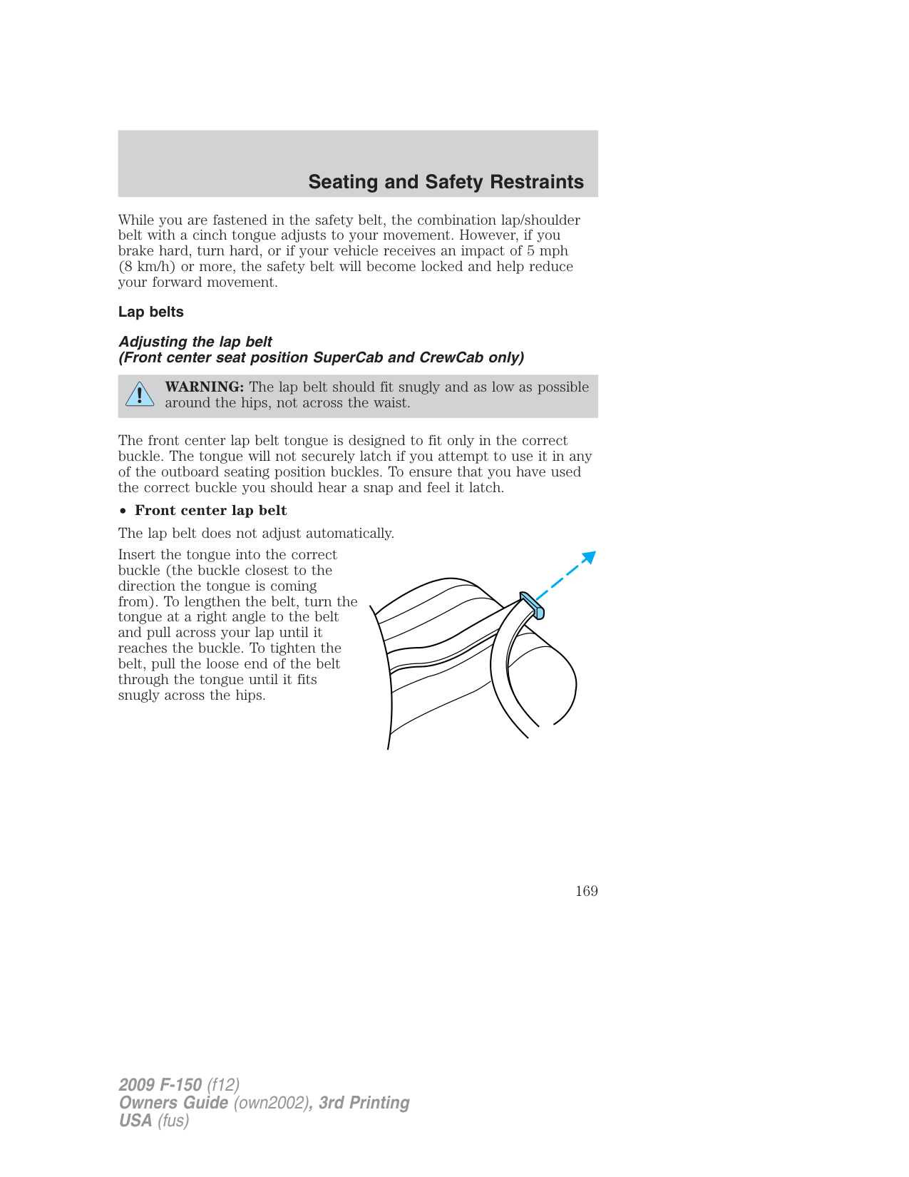
belt.
WARNING: In a rollover crash, an unbelted person is significantly more likely to die than a person wearing a safety
WARNING: Each seating position in your vehicle has a specific safety belt assembly which is made up of one buckle and one
tongue that are designed to be used as a pair. 1) Use the shoulder belt on the outside shoulder only. Never wear the shoulder belt under the arm. 2) Never swing the safety belt around your neck over the inside shoulder. 3) Never use a single belt for more than one person.
WARNING: When possible, all children 12 years old and under should be properly restrained in a rear seating position.
WARNING: Safety belts and seats can become hot in a vehicle that has been closed up in sunny weather; they could burn a
small child. Check seat covers and buckles before you place a child anywhere near them.
WARNING: Front and rear seat occupants, including pregnant women, should wear safety belts for optimum protection in an
accident.
###### Combination lap and shoulder belts
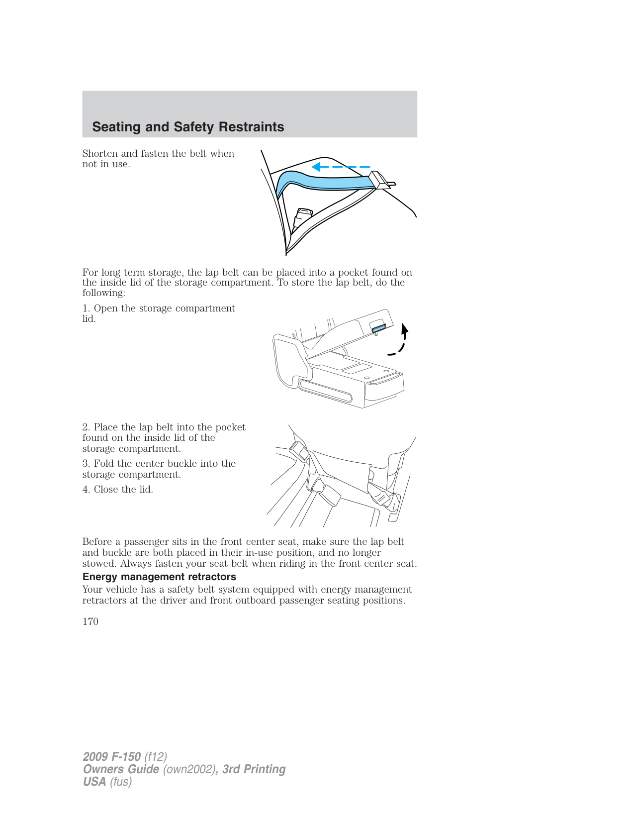
Center front safety belt (Regular Cab center and CrewCab rear center seating positions only)
WARNING: Always use both lap and shoulder safety belt in the Regular Cab center seating position.
If you carry large cargo behind the seat or items that might damage or soil the belt, detach the belt from the seat:
• Release the mini-buckle by inserting a key or similar object into the slot.
If the belt has been disconnected to carry large objects behind the seat, reconnect it as follows:
• Buckle the small tongue on the end of the belt into the mini-buckle on the driver’s side. The belt is now ready for use. This mini-buckle should stay buckled at all times unless cargo-carrying makes it necessary to detach the belt.
###### Safety belt with cinch tongue (Regular Cab center only)
The cinch tongue will slide up and down the belt webbing when the belt is stowed or while putting safety belts on. When the lap/shoulder safety belt is buckled, the cinch tongue will allow the lap portion to be shortened, but pinches the webbing to keep the lap portion from getting longer. The cinch tongue is designed to slip during a crash, so always wear the shoulder belt properly and don’t allow any slack in either the lap or shoulder portions.
Before you can reach and latch a combination lap and shoulder belt having a cinch tongue into the buckle, you may have to lengthen the lap belt portion of it.
WARNING: The lap belt should fit snugly and as low as possible around the hips, not across the waist.
WARNING: Front and rear seat occupants, including pregnant women, should wear safety belts for optimum protection in an
accident.
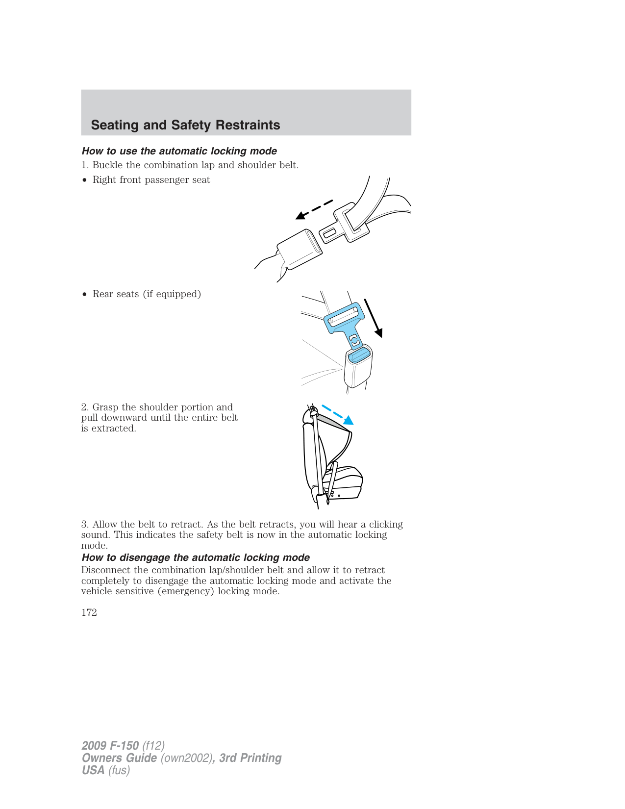
WARNING: Each seating position in your vehicle has a specific safety belt assembly which is made up of one buckle and one
tongue that are designed to be used as a pair. 1) Use the shoulder belt on the outside shoulder only. Never wear the shoulder belt under the arm. 2) Never swing the safety belt around your neck over the inside shoulder. 3) Never use a single belt for more than one person.
While you are fastened in the safety belt, the combination lap/shoulder belt with a cinch tongue adjusts to your movement. However, if you brake hard, turn hard, or if your vehicle receives an impact of 5 mph (8 km/h) or more, the safety belt will become locked and help reduce your forward movement.
Lap belts
Adjusting the lap belt (Front center seat position SuperCab and CrewCab only)
WARNING: The lap belt should fit snugly and as low as possible around the hips, not across the waist.
The front center lap belt tongue is designed to fit only in the correct buckle. The tongue will not securely latch if you attempt to use it in any of the outboard seating position buckles. To ensure that you have used the correct buckle you should hear a snap and feel it latch.
• Front center lap belt The lap belt does not adjust automatically. Insert the tongue into the correct buckle (the buckle closest to the direction the tongue is coming from). To lengthen the belt, turn the tongue at a right angle to the belt and pull across your lap until it reaches the buckle. To tighten the belt, pull the loose end of the belt through the tongue until it fits snugly across the hips.
Shorten and fasten the belt when not in use.
For long term storage, the lap belt can be placed into a pocket found on the inside lid of the storage compartment. To store the lap belt, do the following:
Before a passenger sits in the front center seat, make sure the lap belt and buckle are both placed in their in-use position, and no longer stowed. Always fasten your seat belt when riding in the front center seat. Energy management retractors
Your vehicle has a safety belt system equipped with energy management retractors at the driver and front outboard passenger seating positions.
An energy management retractor is a device which pays out webbing in a controlled manner. This feature is designed to help further reduce the risk of force-related injuries to the occupant.
Safety belt systems equipped with an energy management retractor must be replaced if they were in use during a frontal collision which resulted in deployment of the frontal airbags. Refer to the Safety belt maintenance section in this chapter.
The front and rear safety restraints in the vehicle are combination lap and shoulder belts. The front passenger outboard and rear outboard seat safety belts have two types of locking modes described below:
###### Vehicle sensitive mode
The vehicle sensitive mode is the normal retractor mode, allowing free shoulder belt length adjustment to your movements and locking in response to vehicle movement. For example, if the driver brakes suddenly or turns a corner sharply, or the vehicle receives an impact of approximately 5 mph (8 km/h) or more, the combination safety belts will lock to help reduce forward movement of the driver and passengers.
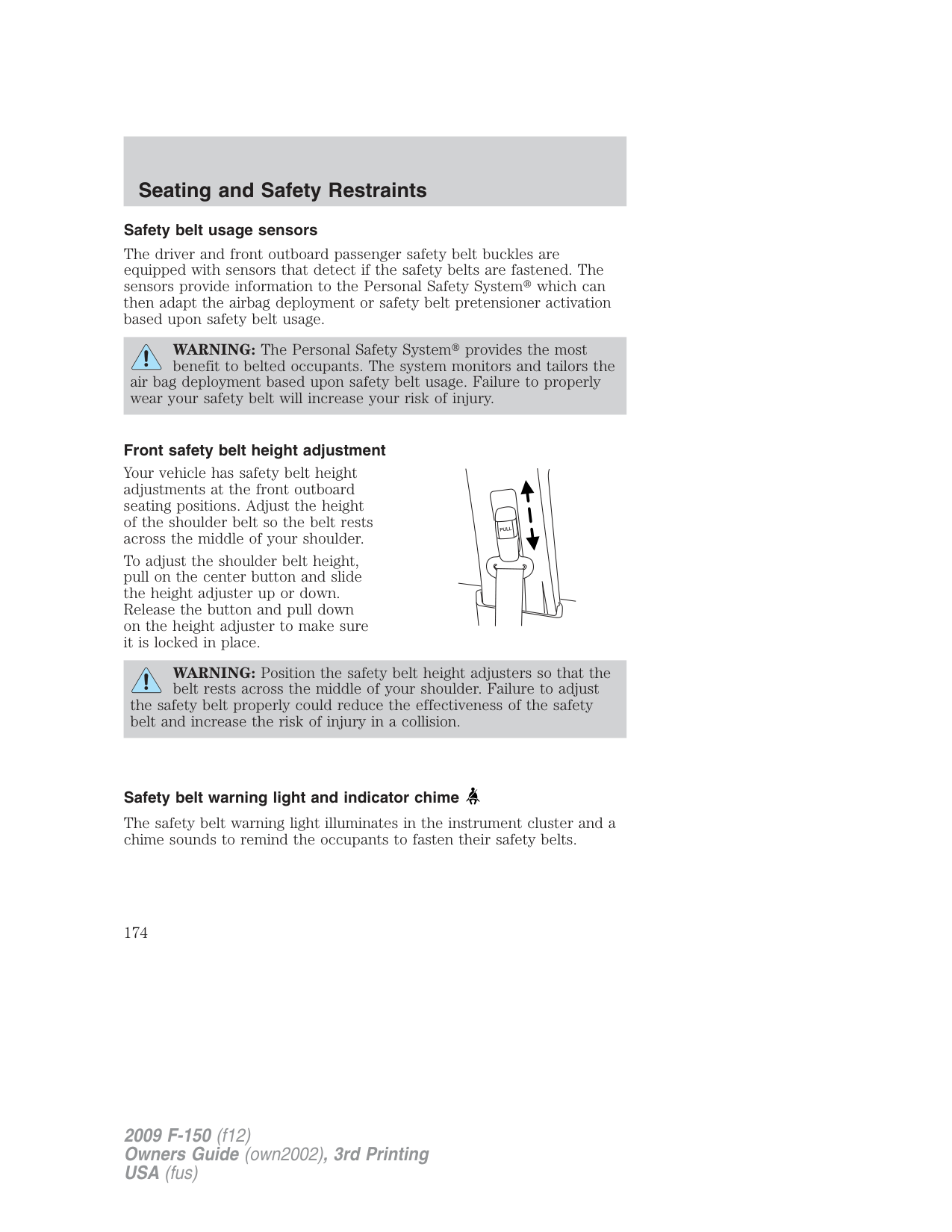
The front outboard safety belts can also be made to lock manually by quickly pulling on the shoulder belt. Rear safety belts (if equipped) can also be made to lock up by pulling quickly on the belt.
###### Automatic locking mode
In this mode, the shoulder belt is automatically pre-locked. The belt will still retract to remove any slack in the shoulder belt.
The automatic locking mode is not available on the driver safety belt, or the Regular Cab center safety belt.
###### When to use the automatic locking mode
• Anytime a child safety seat is installed in a front outboard passenger seating position in a Regular Cab/ SuperCab/ SuperCrew or any rear seating position of a SuperCab or SuperCrew. The Regular Cab front center seatbelt has a cinch mechanism. Refer to Safety belt with cinch tongue (Regular Cab center only) earlier in this chapter. Children 12 years old and under should be properly restrained in a rear seat whenever possible. Refer to Safety restraints for children or Safety seats for children later in this chapter.
###### How to use the automatic locking mode
WARNING: After any vehicle collision, the safety belt systems at all seating positions (except the driver position, which does
not have this feature) must be checked by an authorized dealer to verify that the automatic locking retractor feature for child seats is still functioning properly. In addition, all safety belts should be checked for proper function.
WARNING: BELT AND RETRACTOR ASSEMBLY MUST BE REPLACED if the safety belt assembly “automatic locking
retractor” feature or any other safety belt function is not operating properly when checked by an authorized dealer. Failure to replace the Belt and Retractor assembly could increase the risk of injury in collisions.
###### Safety belt pretensioner
Your vehicle is equipped with safety belt pretensioners at the driver and right front passenger seating positions.
The safety belt pretensioner removes some slack from the safety belt
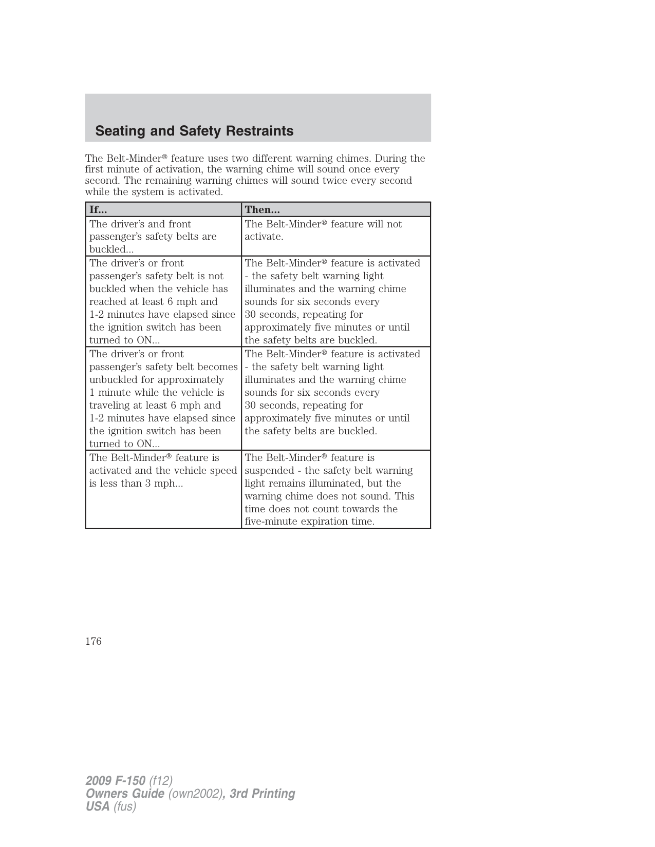
When the Safety Canopy system and/or the front airbags are activated, the safety belt pretensioners for the driver and right front passenger seating positions will be activated when the respective seatbelt is properly buckled.
WARNING: The driver and the right front passenger safety belt system (including retractors, buckles and height adjusters) must
be replaced if the vehicle is involved in a collision that results in deployment of front airbags or Safety Canopy and safety belt pretensioners.
WARNING: Failure to replace the safety belt assembly under the above conditions could result in severe personal injuries in
the event of a collision.
Refer to the Safety belt maintenance section in this chapter.
###### Safety belt usage sensors
The driver and front outboard passenger safety belt buckles are equipped with sensors that detect if the safety belts are fastened. The sensors provide information to the Personal Safety System which can then adapt the airbag deployment or safety belt pretensioner activation based upon safety belt usage.
WARNING: The Personal Safety System provides the most benefit to belted occupants. The system monitors and tailors the
air bag deployment based upon safety belt usage. Failure to properly wear your safety belt will increase your risk of injury.
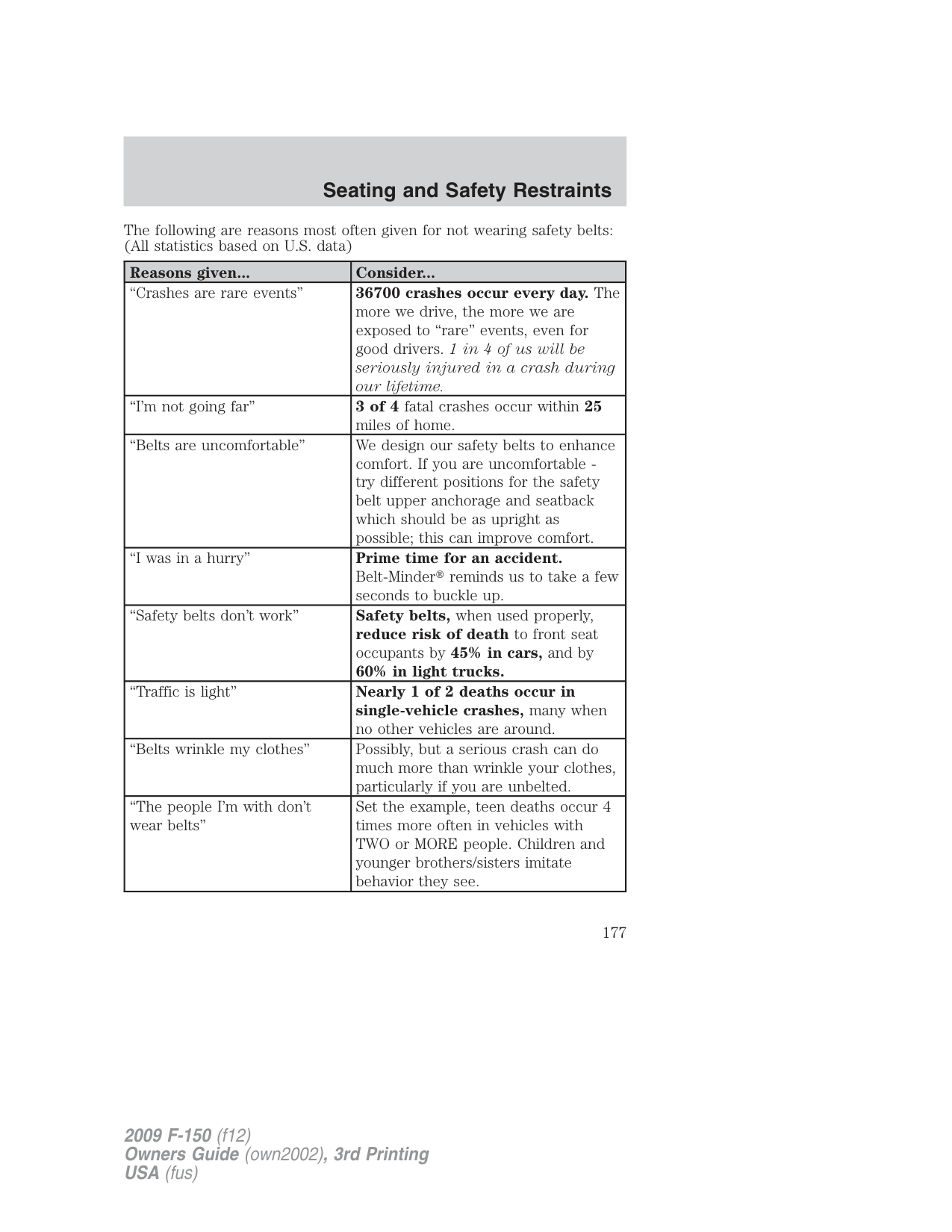
###### Front safety belt height adjustment
Your vehicle has safety belt height adjustments at the front outboard seating positions. Adjust the height of the shoulder belt so the belt rests across the middle of your shoulder.
To adjust the shoulder belt height, pull on the center button and slide the height adjuster up or down. Release the button and pull down on the height adjuster to make sure it is locked in place.
WARNING: Position the safety belt height adjusters so that the belt rests across the middle of your shoulder. Failure to adjust
the safety belt properly could reduce the effectiveness of the safety belt and increase the risk of injury in a collision.
###### Safety belt warning light and indicator chime
The safety belt warning light illuminates in the instrument cluster and a chime sounds to remind the occupants to fasten their safety belts.
Conditions of operation
|If...|Then...| |---|---| |The driver’s safety belt is not buckled before the ignition switch is turned to the on position...|The safety belt warning light illuminates 1-2 minutes and the warning chime sounds 4-8 seconds.|
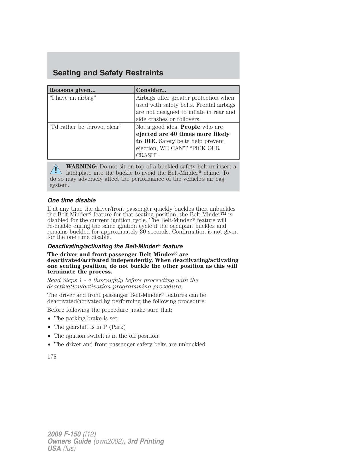
|The driver’s safety belt is buckled while the indicator light is illuminated and the warning chime is sounding...|The safety belt warning light and warning chime turn off.| |The driver’s safety belt is buckled before the ignition switch is turned to the on position...|The safety belt warning light and indicator chime remain off.|
Belt-Minder
The Belt-Minder feature is a supplemental warning to the safety belt warning function. This feature provides additional reminders by intermittently sounding a chime and illuminating the safety belt warning lamp in the instrument cluster when the driver’s and front passenger’s safety belt is unbuckled.
The Belt-Minder feature uses information from the front passenger sensing system to determine if a front seat passenger is present and therefore potentially in need of a warning. To avoid activating the Belt-Minder feature for objects placed in the front passenger seat, warnings will only be given to large front seat occupants as determined by the front passenger sensing system. Both the driver’s and passenger’s safety belt usages are monitored and either may activate the Belt-Minder feature. The warnings are the same for the driver and the front passenger. If the Belt-Minder warnings have expired (warnings for approximately five minutes) for one occupant (driver or front passenger), the other occupant can still activate the Belt-Minder feature. When the Belt-Minder feature is activated, the safety belt warning light illuminates and the warning chime sounds for six seconds every 30 seconds, repeating for approximately five minutes or until the safety belts are buckled.
The Belt-Minder feature uses two different warning chimes. During the first minute of activation, the warning chime will sound once every second. The remaining warning chimes will sound twice every second while the system is activated.
|If...|Then...| |---|---| |The driver’s and front passenger’s safety belts are buckled...|The Belt-Minder feature will not activate.| |The driver’s or front passenger’s safety belt is not buckled when the vehicle has reached at least 6 mph and 1-2 minutes have elapsed since the ignition switch has been turned to ON...|The Belt-Minder feature is activated
- the safety belt warning light illuminates and the warning chime sounds for six seconds every 30 seconds, repeating for approximately five minutes or until the safety belts are buckled.| |The driver’s or front passenger’s safety belt becomes unbuckled for approximately 1 minute while the vehicle is traveling at least 6 mph and 1-2 minutes have elapsed since the ignition switch has been turned to ON...|The Belt-Minder feature is activated
- the safety belt warning light illuminates and the warning chime sounds for six seconds every 30 seconds, repeating for approximately five minutes or until the safety belts are buckled.| |The Belt-Minder feature is activated and the vehicle speed is less than 3 mph...|The Belt-Minder feature is suspended - the safety belt warning light remains illuminated, but the warning chime does not sound. This time does not count towards the five-minute expiration time.|
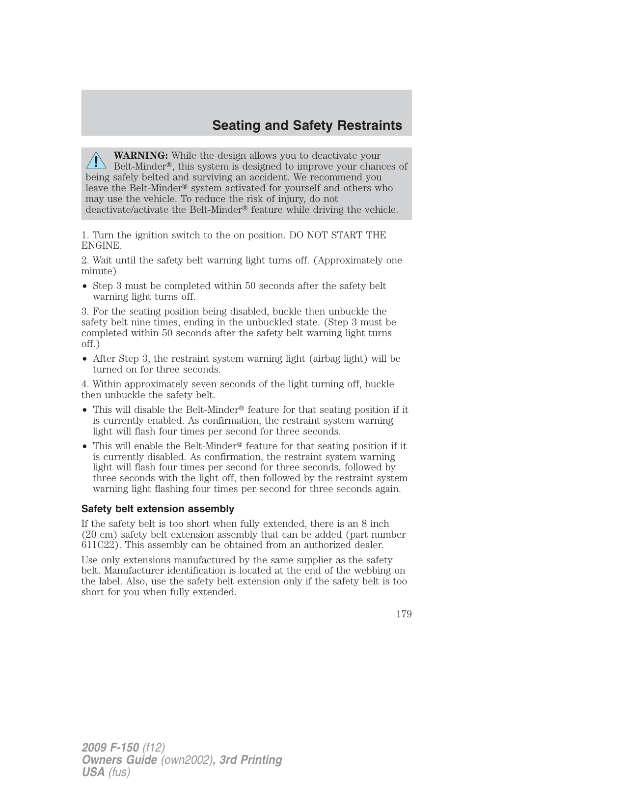
####### The following are reasons most often given for not wearing safety belts: (All statistics based on U.S. data)
|Reasons given...|Consider...| |---|---| |“Crashes are rare events”|36700 crashes occur every day. The more we drive, the more we are exposed to “rare” events, even for good drivers. 1in4ofuswillbe seriously injured in a crash during our lifetime.| |“I’m not going far”|3of4fatal crashes occur within 25 miles of home.| |“Belts are uncomfortable”|We design our safety belts to enhance comfort. If you are uncomfortable try different positions for the safety belt upper anchorage and seatback which should be as upright as possible; this can improve comfort.| |“I was in a hurry”|Prime time for an accident. Belt-Minder reminds us to take a few seconds to buckle up.| |“Safety belts don’t work”|Safety belts, when used properly, reduce risk of death to front seat occupants by 45% in cars, and by 60% in light trucks.| |“Traffic is light”|Nearly 1 of 2 deaths occur in single-vehicle crashes, many when no other vehicles are around.| |“Belts wrinkle my clothes”|Possibly, but a serious crash can do much more than wrinkle your clothes, particularly if you are unbelted.| |“The people I’m with don’t wear belts”|Set the example, teen deaths occur 4 times more often in vehicles with TWO or MORE people. Children and younger brothers/sisters imitate behavior they see.|
|Reasons given...|Consider...| |---|---| |“I have an airbag”|Airbags offer greater protection when used with safety belts. Frontal airbags are not designed to inflate in rear and side crashes or rollovers.| |“I’d rather be thrown clear”|Not a good idea. People who are ejected are 40 times more likely to DIE. Safety belts help prevent ejection, WE CAN’T “PICK OUR CRASH”.|
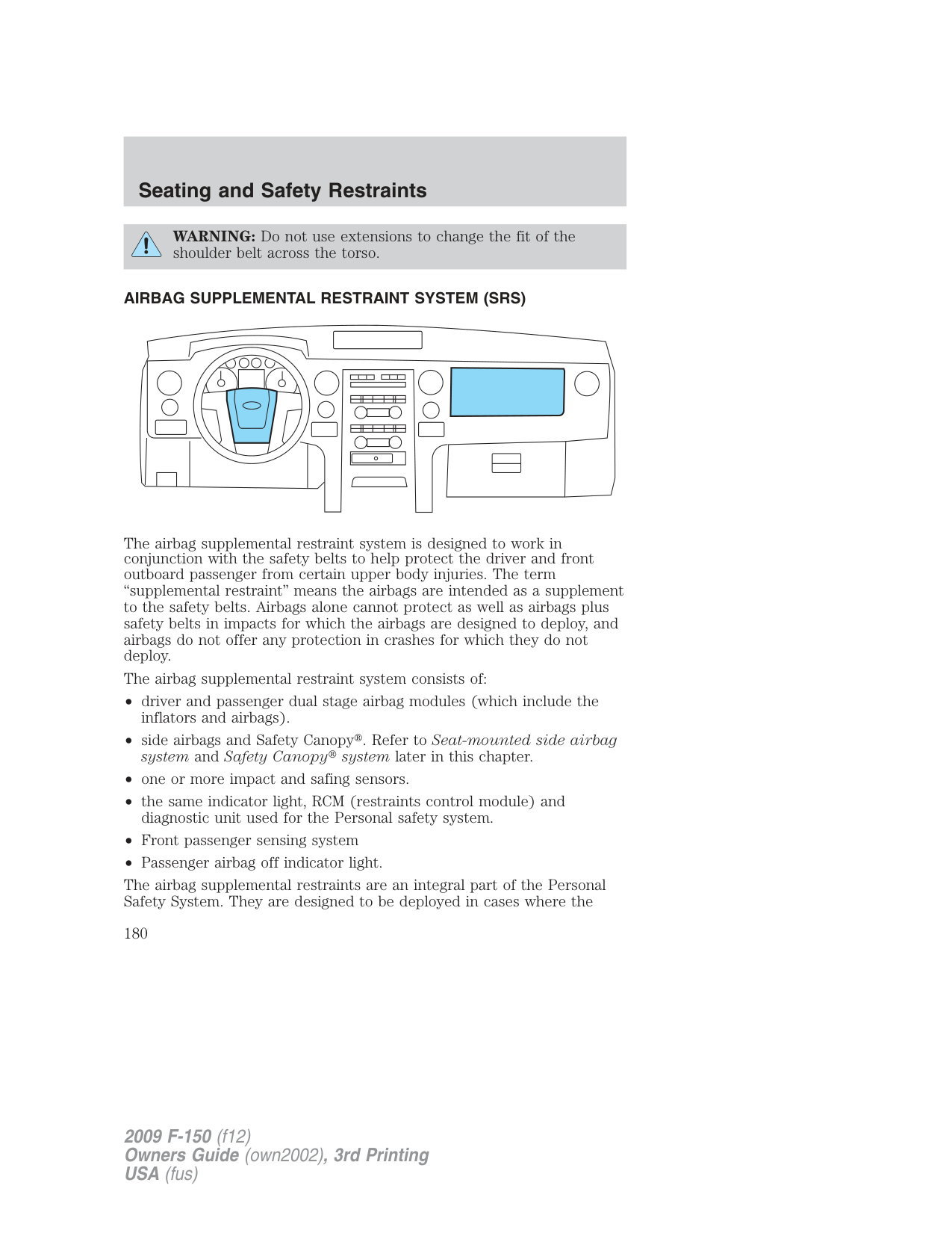
WARNING: Do not sit on top of a buckled safety belt or insert a latchplate into the buckle to avoid the Belt-Minder chime. To
do so may adversely affect the performance of the vehicle’s air bag system.
###### One time disable
If at any time the driver/front passenger quickly buckles then unbuckles the Belt-Minder feature for that seating position, the Belt-Minder™ is disabled for the current ignition cycle. The Belt-Minder feature will re-enable during the same ignition cycle if the occupant buckles and remains buckled for approximately 30 seconds. Confirmation is not given for the one time disable.
Deactivating/activating the Belt-Minder feature
The driver and front passenger Belt-Minder are deactivated/activated independently. When deactivating/activating one seating position, do not buckle the other position as this will terminate the process.
Read Steps1-4thoroughly before proceeding with the deactivation/activation programming procedure.
The driver and front passenger Belt-Minder features can be deactivated/activated by performing the following procedure:
Before following the procedure, make sure that:
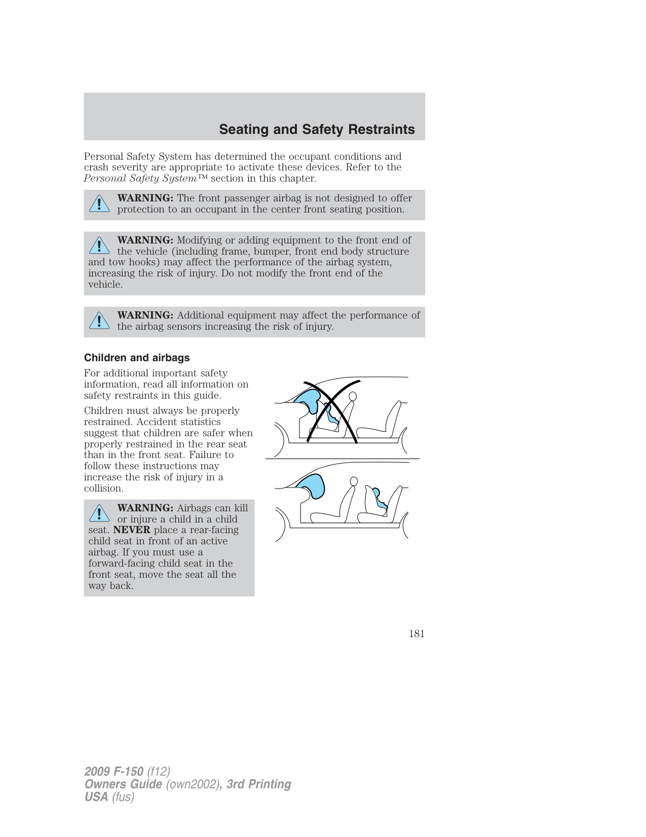
WARNING: While the design allows you to deactivate your Belt-Minder , this system is designed to improve your chances of
being safely belted and surviving an accident. We recommend you leave the Belt-Minder system activated for yourself and others who may use the vehicle. To reduce the risk of injury, do not deactivate/activate the Belt-Minder feature while driving the vehicle.
• Step 3 must be completed within 50 seconds after the safety belt
warning light turns off.
• After Step 3, the restraint system warning light (airbag light) will be
turned on for three seconds.
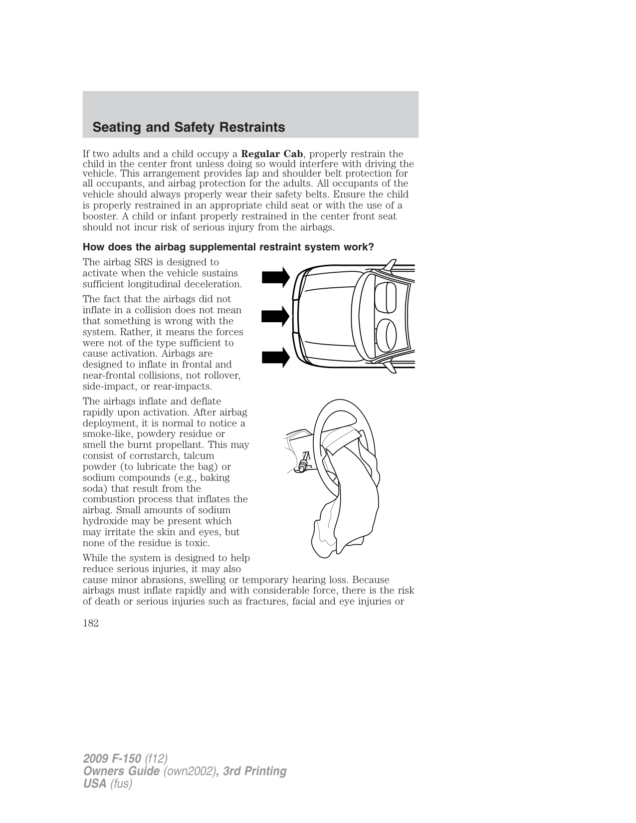
###### Safety belt extension assembly
If the safety belt is too short when fully extended, there is an 8 inch (20 cm) safety belt extension assembly that can be added (part number 611C22). This assembly can be obtained from an authorized dealer.
Use only extensions manufactured by the same supplier as the safety belt. Manufacturer identification is located at the end of the webbing on the label. Also, use the safety belt extension only if the safety belt is too short for you when fully extended.
WARNING: Do not use extensions to change the fit of the shoulder belt across the torso.
###### AIRBAG SUPPLEMENTAL RESTRAINT SYSTEM (SRS)
| | | | |---|---|---|
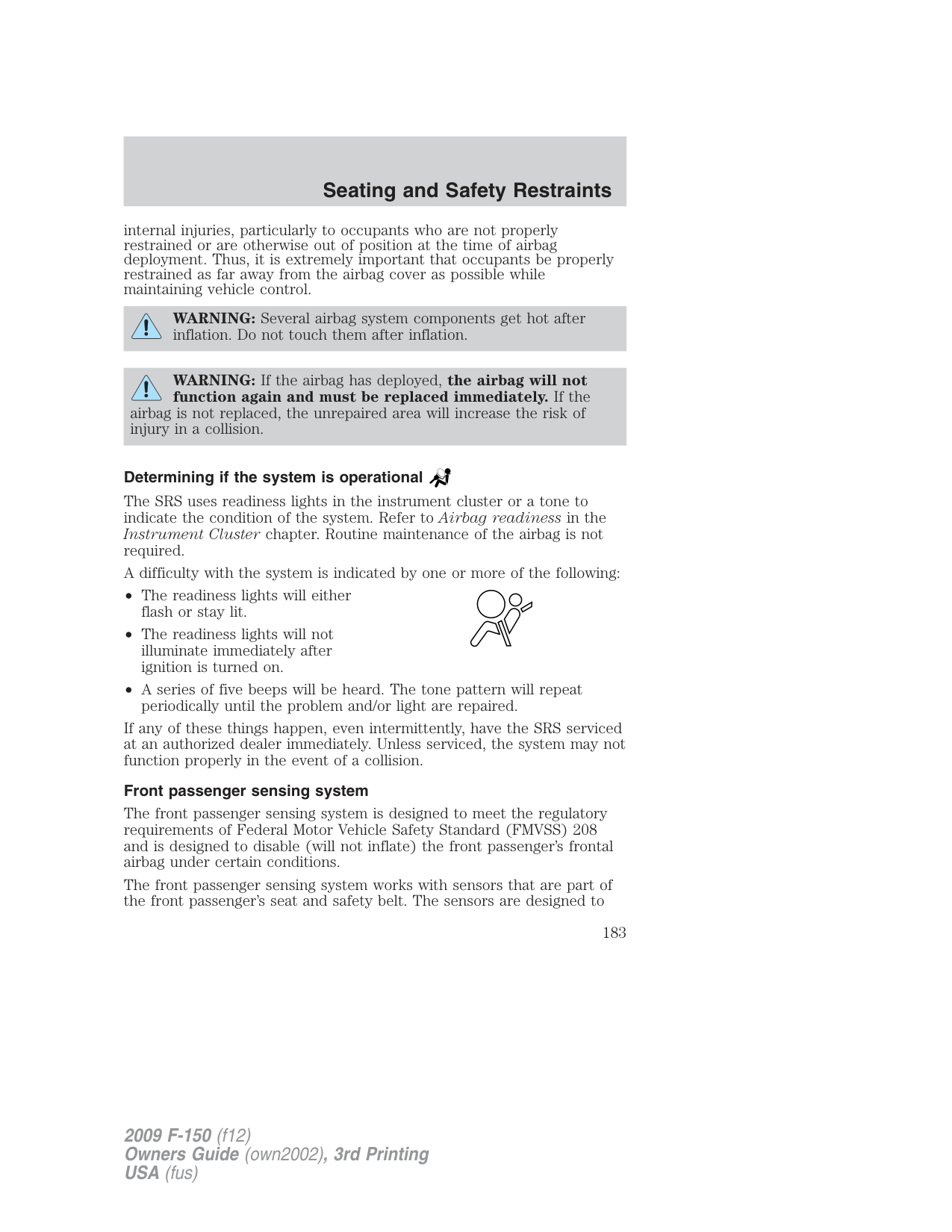
| | | | |---|---|---|
| | | | | | |---|---|---|---|---| | | | | | |
| | | | | | |---|---|---|---|---| | | | | | |
The airbag supplemental restraint system is designed to work in conjunction with the safety belts to help protect the driver and front outboard passenger from certain upper body injuries. The term “supplemental restraint” means the airbags are intended as a supplement to the safety belts. Airbags alone cannot protect as well as airbags plus safety belts in impacts for which the airbags are designed to deploy, and airbags do not offer any protection in crashes for which they do not deploy.
The airbag supplemental restraint system consists of:
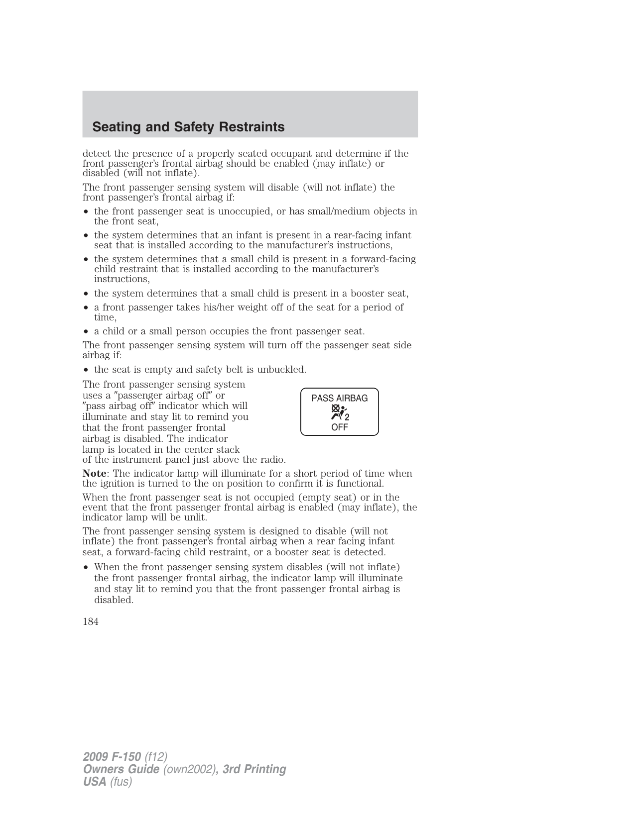
The airbag supplemental restraints are an integral part of the Personal Safety System. They are designed to be deployed in cases where the
Personal Safety System has determined the occupant conditions and crash severity are appropriate to activate these devices. Refer to the Personal Safety System™ section in this chapter.
WARNING: The front passenger airbag is not designed to offer protection to an occupant in the center front seating position.
WARNING: Modifying or adding equipment to the front end of the vehicle (including frame, bumper, front end body structure
and tow hooks) may affect the performance of the airbag system, increasing the risk of injury. Do not modify the front end of the vehicle.
WARNING: Additional equipment may affect the performance of the airbag sensors increasing the risk of injury.
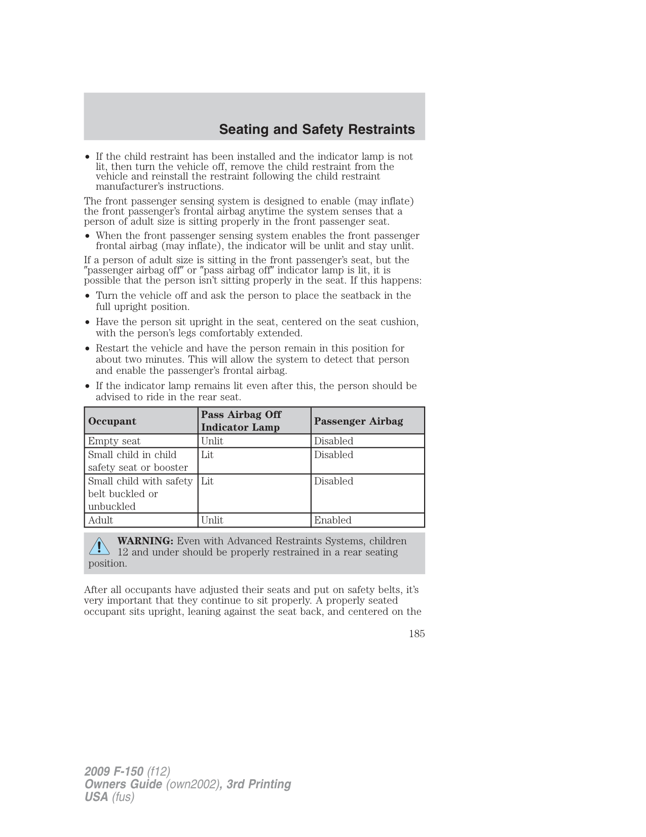
###### Children and airbags
For additional important safety information, read all information on safety restraints in this guide.
Children must always be properly restrained. Accident statistics suggest that children are safer when properly restrained in the rear seat than in the front seat. Failure to follow these instructions may increase the risk of injury in a collision.
WARNING: Airbags can kill or injure a child in a child
seat. NEVER place a rear-facing child seat in front of an active airbag. If you must use a forward-facing child seat in the front seat, move the seat all the way back.
If two adults and a child occupy a Regular Cab, properly restrain the child in the center front unless doing so would interfere with driving the vehicle. This arrangement provides lap and shoulder belt protection for all occupants, and airbag protection for the adults. All occupants of the vehicle should always properly wear their safety belts. Ensure the child is properly restrained in an appropriate child seat or with the use of a booster. A child or infant properly restrained in the center front seat should not incur risk of serious injury from the airbags.
###### How does the airbag supplemental restraint system work?
The airbag SRS is designed to activate when the vehicle sustains sufficient longitudinal deceleration.
The fact that the airbags did not inflate in a collision does not mean that something is wrong with the system. Rather, it means the forces were not of the type sufficient to cause activation. Airbags are designed to inflate in frontal and near-frontal collisions, not rollover, side-impact, or rear-impacts.
The airbags inflate and deflate rapidly upon activation. After airbag deployment, it is normal to notice a smoke-like, powdery residue or smell the burnt propellant. This may consist of cornstarch, talcum powder (to lubricate the bag) or sodium compounds (e.g., baking soda) that result from the combustion process that inflates the airbag. Small amounts of sodium hydroxide may be present which may irritate the skin and eyes, but none of the residue is toxic.
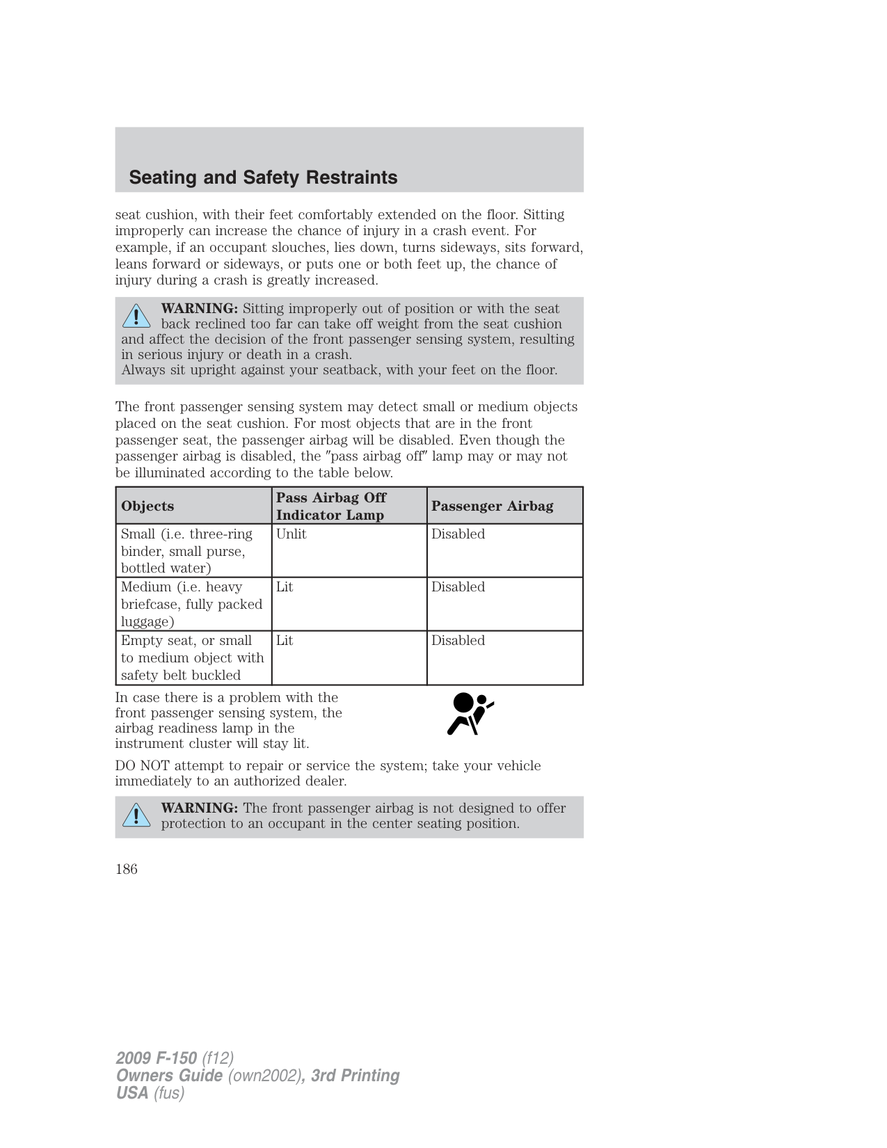
While the system is designed to help reduce serious injuries, it may also cause minor abrasions, swelling or temporary hearing loss. Because airbags must inflate rapidly and with considerable force, there is the risk of death or serious injuries such as fractures, facial and eye injuries or
internal injuries, particularly to occupants who are not properly restrained or are otherwise out of position at the time of airbag deployment. Thus, it is extremely important that occupants be properly restrained as far away from the airbag cover as possible while maintaining vehicle control.
WARNING: Several airbag system components get hot after inflation. Do not touch them after inflation.
###### WARNING: If the airbag has deployed, the airbag will not function again and must be replaced immediately. If the
airbag is not replaced, the unrepaired area will increase the risk of injury in a collision.
###### Determining if the system is operational
The SRS uses readiness lights in the instrument cluster or a tone to indicate the condition of the system. Refer to Airbag readiness in the Instrument Cluster chapter. Routine maintenance of the airbag is not required.
A difficulty with the system is indicated by one or more of the following:
• The readiness lights will either
flash or stay lit.
periodically until the problem and/or light are repaired.
If any of these things happen, even intermittently, have the SRS serviced at an authorized dealer immediately. Unless serviced, the system may not function properly in the event of a collision.
###### Front passenger sensing system
The front passenger sensing system is designed to meet the regulatory requirements of Federal Motor Vehicle Safety Standard (FMVSS) 208 and is designed to disable (will not inflate) the front passenger’s frontal airbag under certain conditions.
The front passenger sensing system works with sensors that are part of the front passenger’s seat and safety belt. The sensors are designed to
detect the presence of a properly seated occupant and determine if the front passenger’s frontal airbag should be enabled (may inflate) or disabled (will not inflate).
The front passenger sensing system will disable (will not inflate) the front passenger’s frontal airbag if:
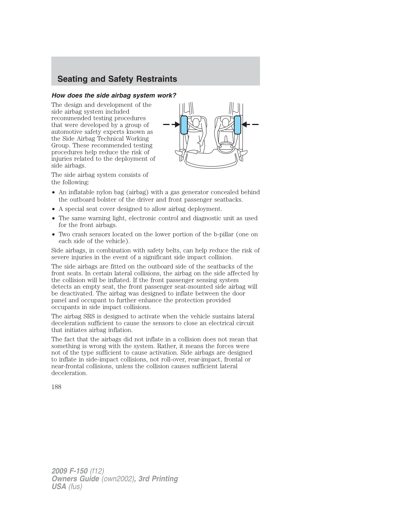
The front passenger sensing system will turn off the passenger seat side airbag if:
The front passenger sensing system uses a passenger airbag off or
pass airbag off indicator which will illuminate and stay lit to remind you that the front passenger frontal airbag is disabled. The indicator lamp is located in the center stack of the instrument panel just above the radio. Note: The indicator lamp will illuminate for a short period of time when the ignition is turned to the on position to confirm it is functional. When the front passenger seat is not occupied (empty seat) or in the event that the front passenger frontal airbag is enabled (may inflate), the indicator lamp will be unlit. The front passenger sensing system is designed to disable (will not inflate) the front passenger’s frontal airbag when a rear facing infant seat, a forward-facing child restraint, or a booster seat is detected.
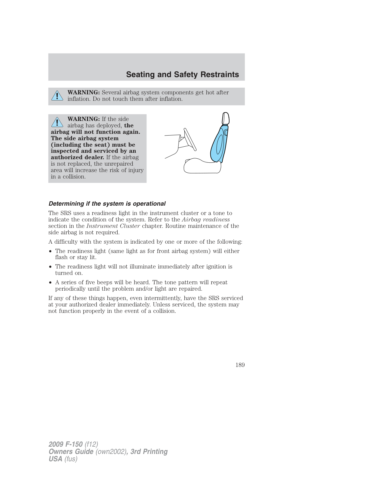
The front passenger sensing system is designed to enable (may inflate) the front passenger’s frontal airbag anytime the system senses that a person of adult size is sitting properly in the front passenger seat.
• When the front passenger sensing system enables the front passenger
frontal airbag (may inflate), the indicator will be unlit and stay unlit. If a person of adult size is sitting in the front passenger’s seat, but the
passenger airbag off or pass airbag off indicator lamp is lit, it is possible that the person isn’t sitting properly in the seat. If this happens:
|Occupant|Pass Airbag Off Indicator Lamp|Passenger Airbag| |---|---|---| |Empty seat|Unlit|Disabled| |Small child in child safety seat or booster|Lit|Disabled| |Small child with safety belt buckled or unbuckled|Lit|Disabled| |Adult|Unlit|Enabled|
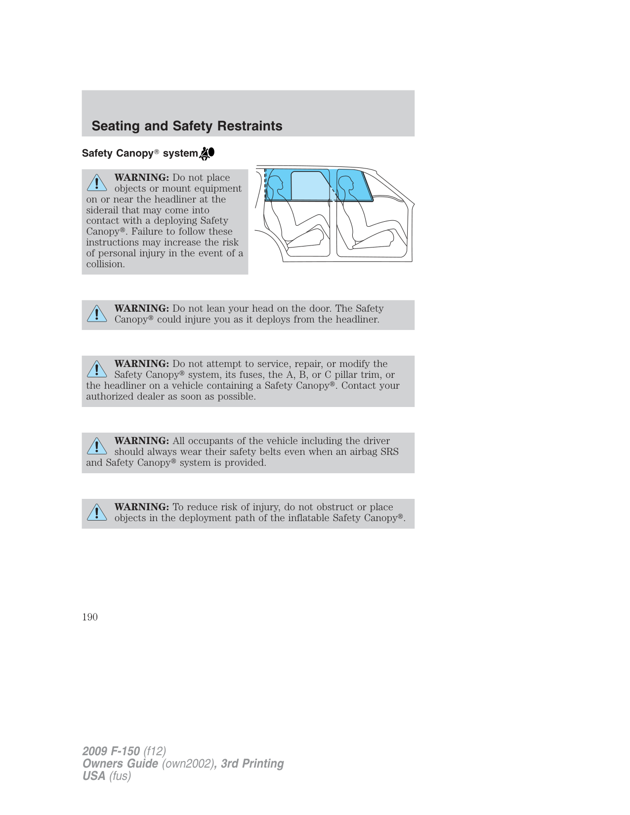
WARNING: Even with Advanced Restraints Systems, children 12 and under should be properly restrained in a rear seating
position.
After all occupants have adjusted their seats and put on safety belts, it’s very important that they continue to sit properly. A properly seated occupant sits upright, leaning against the seat back, and centered on the
seat cushion, with their feet comfortably extended on the floor. Sitting improperly can increase the chance of injury in a crash event. For example, if an occupant slouches, lies down, turns sideways, sits forward, leans forward or sideways, or puts one or both feet up, the chance of injury during a crash is greatly increased.
WARNING: Sitting improperly out of position or with the seat back reclined too far can take off weight from the seat cushion
and affect the decision of the front passenger sensing system, resulting in serious injury or death in a crash. Always sit upright against your seatback, with your feet on the floor.
The front passenger sensing system may detect small or medium objects placed on the seat cushion. For most objects that are in the front passenger seat, the passenger airbag will be disabled. Even though the passenger airbag is disabled, the pass airbag off lamp may or may not be illuminated according to the table below.
|Objects|Pass Airbag Off Indicator Lamp|Passenger Airbag| |---|---|---| |Small (i.e. three-ring binder, small purse, bottled water)|Unlit|Disabled| |Medium (i.e. heavy briefcase, fully packed luggage)|Lit|Disabled|
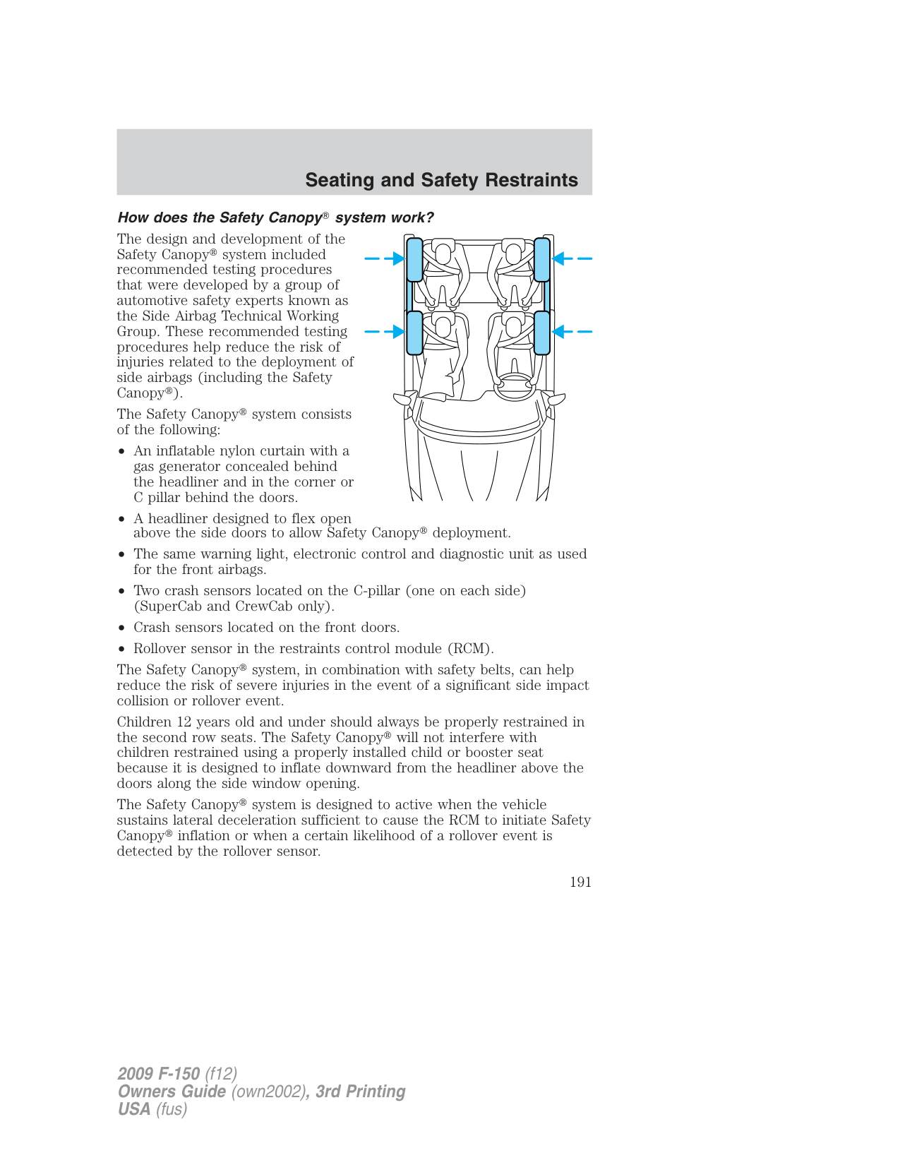
|Empty seat, or small to medium object with safety belt buckled|Lit|Disabled|
In case there is a problem with the front passenger sensing system, the airbag readiness lamp in the instrument cluster will stay lit.
DO NOT attempt to repair or service the system; take your vehicle immediately to an authorized dealer.
WARNING: The front passenger airbag is not designed to offer protection to an occupant in the center seating position.
WARNING: An out of position front center occupant could affect the decision of the front passenger sensing system.
If it is necessary to modify an advanced front airbag system to accommodate a person with disabilities, contact the Ford Customer Relationship Center at the phone number shown in the Customer Assistance section of this Owner’s Guide.
WARNING: Any alteration/modification to the front passenger seat may affect the performance of the front passenger sensing
system.
###### Seat-mounted side airbag system
WARNING: Do not place objects or mount equipment on or near the airbag cover on the side of the seatbacks of the front
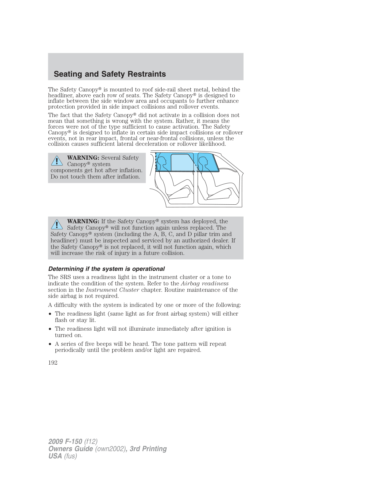
seats or in front seat areas that may come into contact with a deploying airbag. Failure to follow these instructions may increase the risk of personal injury in the event of a collision.
WARNING: Do not use accessory seat covers. The use of accessory seat covers may prevent the deployment of the side
airbags and increase the risk of injury in an accident.
WARNING: Do not lean your head on the door. The side airbag could injure you as it deploys from the side of the seatback.
WARNING: Do not attempt to service, repair, or modify the airbag SRS, its fuses or the seat cover on a seat containing an
airbag. See an authorized dealer.
WARNING: All occupants of the vehicle should always wear their safety belts even when an airbag SRS is provided.
###### How does the side airbag system work?
The design and development of the side airbag system included recommended testing procedures that were developed by a group of automotive safety experts known as the Side Airbag Technical Working Group. These recommended testing procedures help reduce the risk of injuries related to the deployment of side airbags.
The side airbag system consists of the following:
Side airbags, in combination with safety belts, can help reduce the risk of severe injuries in the event of a significant side impact collision.
The side airbags are fitted on the outboard side of the seatbacks of the front seats. In certain lateral collisions, the airbag on the side affected by the collision will be inflated. If the front passenger sensing system detects an empty seat, the front passenger seat-mounted side airbag will be deactivated. The airbag was designed to inflate between the door panel and occupant to further enhance the protection provided occupants in side impact collisions.
The airbag SRS is designed to activate when the vehicle sustains lateral deceleration sufficient to cause the sensors to close an electrical circuit that initiates airbag inflation.
The fact that the airbags did not inflate in a collision does not mean that something is wrong with the system. Rather, it means the forces were not of the type sufficient to cause activation. Side airbags are designed to inflate in side-impact collisions, not roll-over, rear-impact, frontal or near-frontal collisions, unless the collision causes sufficient lateral deceleration.
WARNING: Several airbag system components get hot after inflation. Do not touch them after inflation.
WARNING: If the side airbag has deployed, the
airbag will not function again. The side airbag system (including the seat) must be inspected and serviced by an authorized dealer. If the airbag is not replaced, the unrepaired area will increase the risk of injury in a collision.
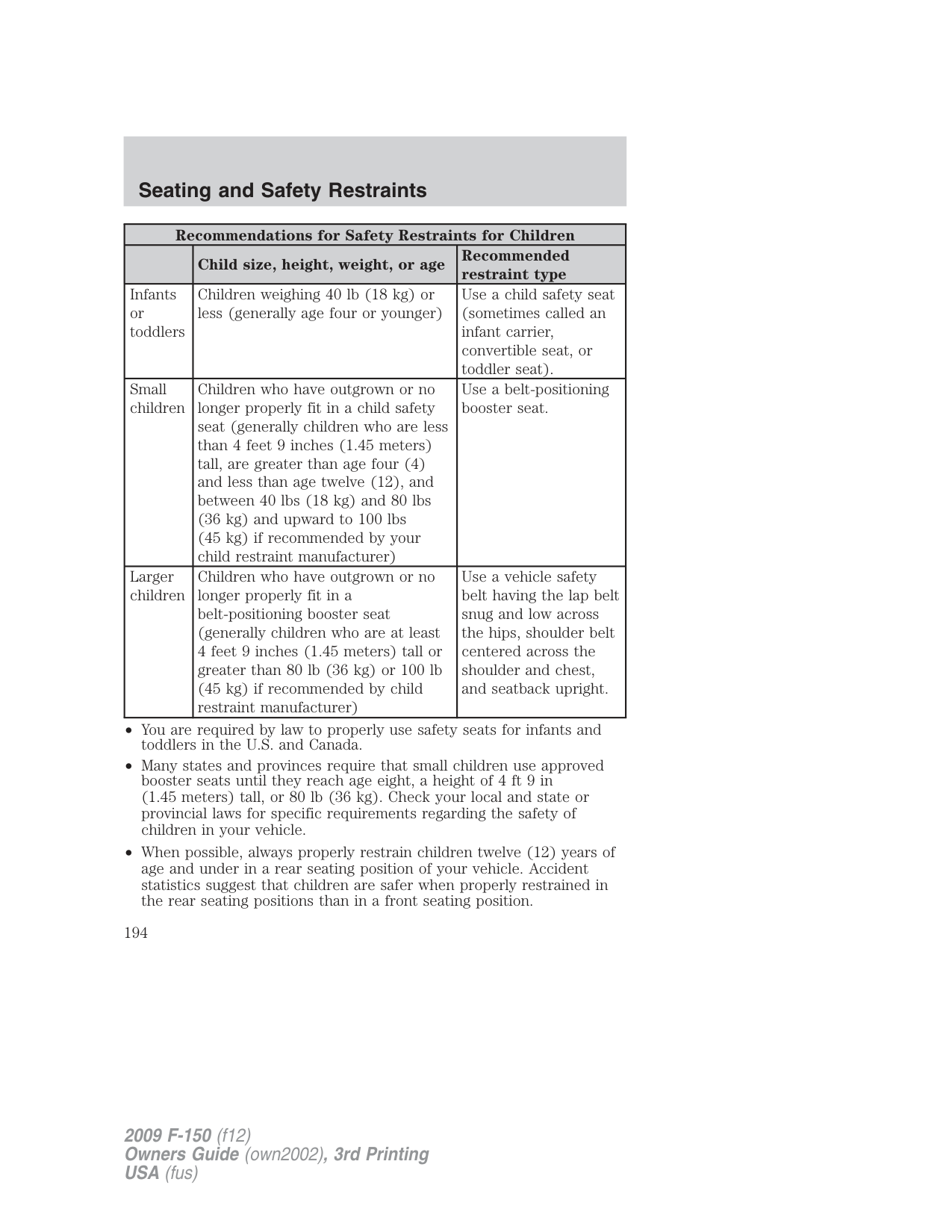
Determining if the system is operational
The SRS uses a readiness light in the instrument cluster or a tone to indicate the condition of the system. Refer to the Airbag readiness section in the Instrument Cluster chapter. Routine maintenance of the side airbag is not required.
A difficulty with the system is indicated by one or more of the following:
• The readiness light (same light as for front airbag system) will either
flash or stay lit.
• The readiness light will not illuminate immediately after ignition is
turned on.
• A series of five beeps will be heard. The tone pattern will repeat
periodically until the problem and/or light are repaired.
If any of these things happen, even intermittently, have the SRS serviced at your authorized dealer immediately. Unless serviced, the system may not function properly in the event of a collision.
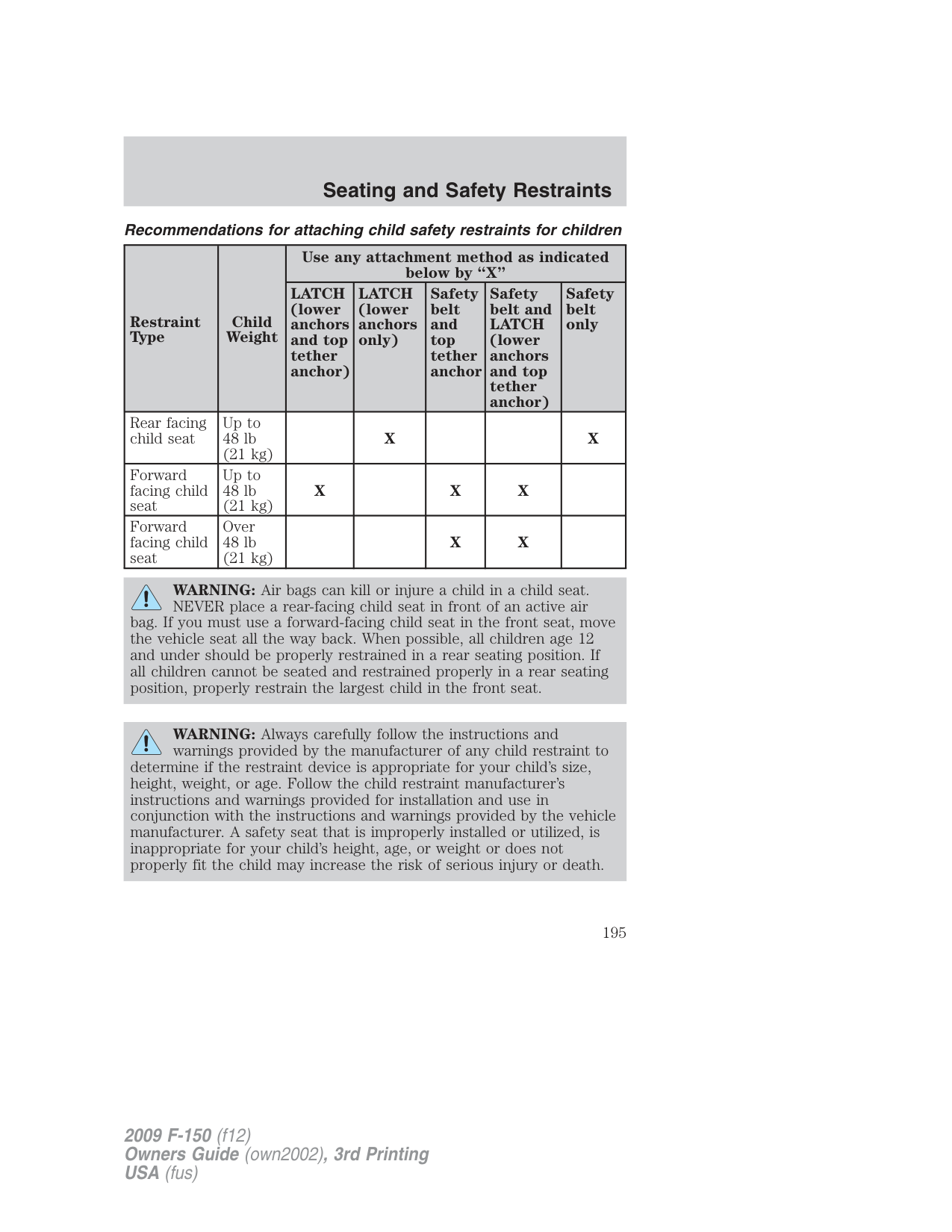
###### Safety Canopy system
WARNING: Do not place objects or mount equipment
on or near the headliner at the siderail that may come into contact with a deploying Safety Canopy . Failure to follow these instructions may increase the risk of personal injury in the event of a collision.
WARNING: Do not lean your head on the door. The Safety Canopy could injure you as it deploys from the headliner.
WARNING: Do not attempt to service, repair, or modify the Safety Canopy system, its fuses, the A, B, or C pillar trim, or
the headliner on a vehicle containing a Safety Canopy . Contact your authorized dealer as soon as possible.
WARNING: All occupants of the vehicle including the driver should always wear their safety belts even when an airbag SRS
and Safety Canopy system is provided.
WARNING: To reduce risk of injury, do not obstruct or place objects in the deployment path of the inflatable Safety Canopy .
###### How does the Safety Canopy system work?
The design and development of the Safety Canopy system included recommended testing procedures that were developed by a group of automotive safety experts known as the Side Airbag Technical Working Group. These recommended testing procedures help reduce the risk of injuries related to the deployment of side airbags (including the Safety Canopy ).
The Safety Canopy system consists of the following:
The Safety Canopy system, in combination with safety belts, can help reduce the risk of severe injuries in the event of a significant side impact collision or rollover event.
Children 12 years old and under should always be properly restrained in the second row seats. The Safety Canopy will not interfere with children restrained using a properly installed child or booster seat because it is designed to inflate downward from the headliner above the doors along the side window opening.
The Safety Canopy system is designed to active when the vehicle sustains lateral deceleration sufficient to cause the RCM to initiate Safety Canopy inflation or when a certain likelihood of a rollover event is detected by the rollover sensor.
The Safety Canopy is mounted to roof side-rail sheet metal, behind the headliner, above each row of seats. The Safety Canopy is designed to inflate between the side window area and occupants to further enhance protection provided in side impact collisions and rollover events.
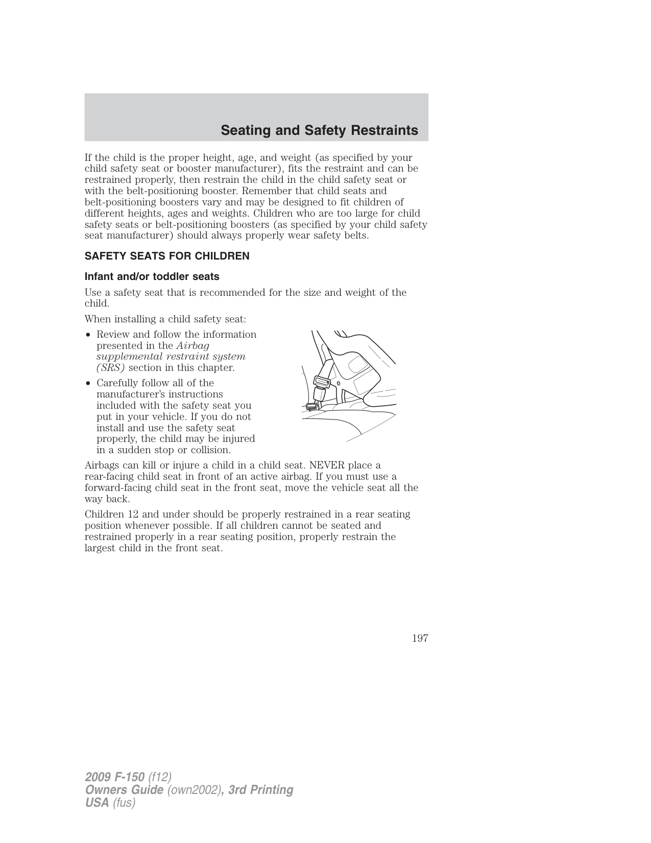
The fact that the Safety Canopy did not activate in a collision does not mean that something is wrong with the system. Rather, it means the forces were not of the type sufficient to cause activation. The Safety Canopy is designed to inflate in certain side impact collisions or rollover events, not in rear impact, frontal or near-frontal collisions, unless the collision causes sufficient lateral deceleration or rollover likelihood.
WARNING: Several Safety Canopy system
components get hot after inflation. Do not touch them after inflation.
WARNING: If the Safety Canopy system has deployed, the Safety Canopy will not function again unless replaced. The
Safety Canopy system (including the A, B, C, and D pillar trim and headliner) must be inspected and serviced by an authorized dealer. If the Safety Canopy is not replaced, it will not function again, which will increase the risk of injury in a future collision.
Determining if the system is operational The SRS uses a readiness light in the instrument cluster or a tone to indicate the condition of the system. Refer to the Airbag readiness section in the Instrument Cluster chapter. Routine maintenance of the side airbag is not required. A difficulty with the system is indicated by one or more of the following:
If any of these things happen, even intermittently, have the SRS serviced at your authorized dealer immediately. Unless serviced, the system may not function properly in the event of a collision.
Disposal of airbags and airbag equipped vehicles (including pretensioners)
Contact your authorized dealer as soon as possible. Airbags MUST BE disposed of by qualified personnel. SAFETY RESTRAINTS FOR CHILDREN
See the following sections for directions on how to properly use safety restraints for children. Also see Airbag supplemental restraint system (SRS) in this chapter for special instructions about using airbags. Important child restraint precautions
WARNING: Always make sure your child is secured properly in a device that is appropriate for their height, age and weight.
Child safety restraints must be purchased separately from the vehicle. Failure to follow these instructions and guidelines may result in an increased risk of serious injury or death to your child.
WARNING: All children are shaped differently. The Recommendations for Safety Restraints are based on probable
child height, age and weight thresholds from NHTSA and other safety organizations or are the minimum requirements of law. Ford recommends checking with a NHTSA Certified Child Passenger Safety Technician (CPST) and your pediatrician to make sure your child seat is appropriate for your child, and is compatible with and properly installed in the vehicle. To locate a child seat fitting station and CPST contact the NHTSA toll free at 1-888-327-4236 or on the internet at http://www.nhtsa.dot.gov. Failure to properly restrain children in safety seats made especially for their height, age, and weight may result in an increased risk of serious injury or death to your child.
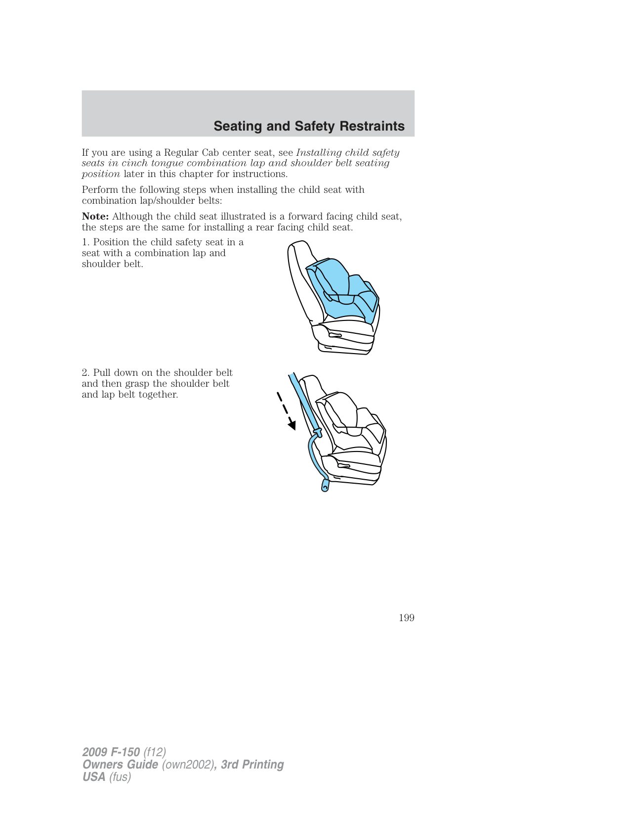
|Recommendations for Safety Restraints for Children|Recommendations for Safety Restraints for Children|Recommendations for Safety Restraints for Children| |---|---|---| | |Child size, height, weight, or age|Recommended restraint type| |Infants or toddlers|Children weighing 40 lb (18 kg) or less (generally age four or younger)|Use a child safety seat (sometimes called an infant carrier, convertible seat, or toddler seat).| |Small children|Children who have outgrown or no longer properly fit in a child safety seat (generally children who are less than 4 feet 9 inches (1.45 meters) tall, are greater than age four (4) and less than age twelve (12), and between 40 lbs (18 kg) and 80 lbs (36 kg) and upward to 100 lbs (45 kg) if recommended by your child restraint manufacturer)|Use a belt-positioning booster seat.| |Larger children|Children who have outgrown or no longer properly fit in a belt-positioning booster seat (generally children who are at least 4 feet 9 inches (1.45 meters) tall or greater than 80 lb (36 kg) or 100 lb (45 kg) if recommended by child restraint manufacturer)|Use a vehicle safety belt having the lap belt snug and low across the hips, shoulder belt centered across the shoulder and chest, and seatback upright.|
Recommendations for attaching child safety restraints for children
|Restraint Type|Child Weight|Use any attachment method as indicated below by “X”|Use any attachment method as indicated below by “X”|Use any attachment method as indicated below by “X”|Use any attachment method as indicated below by “X”|Use any attachment method as indicated below by “X”| |---|---|---|---|---|---|---| |Restraint Type|Child Weight|LATCH (lower anchors and top tether anchor)|LATCH (lower anchors only)|Safety belt and top tether anchor|Safety belt and LATCH (lower anchors and top tether anchor)|Safety belt only| |Rear facing child seat|Up to 48 lb (21 kg)| | | | | |
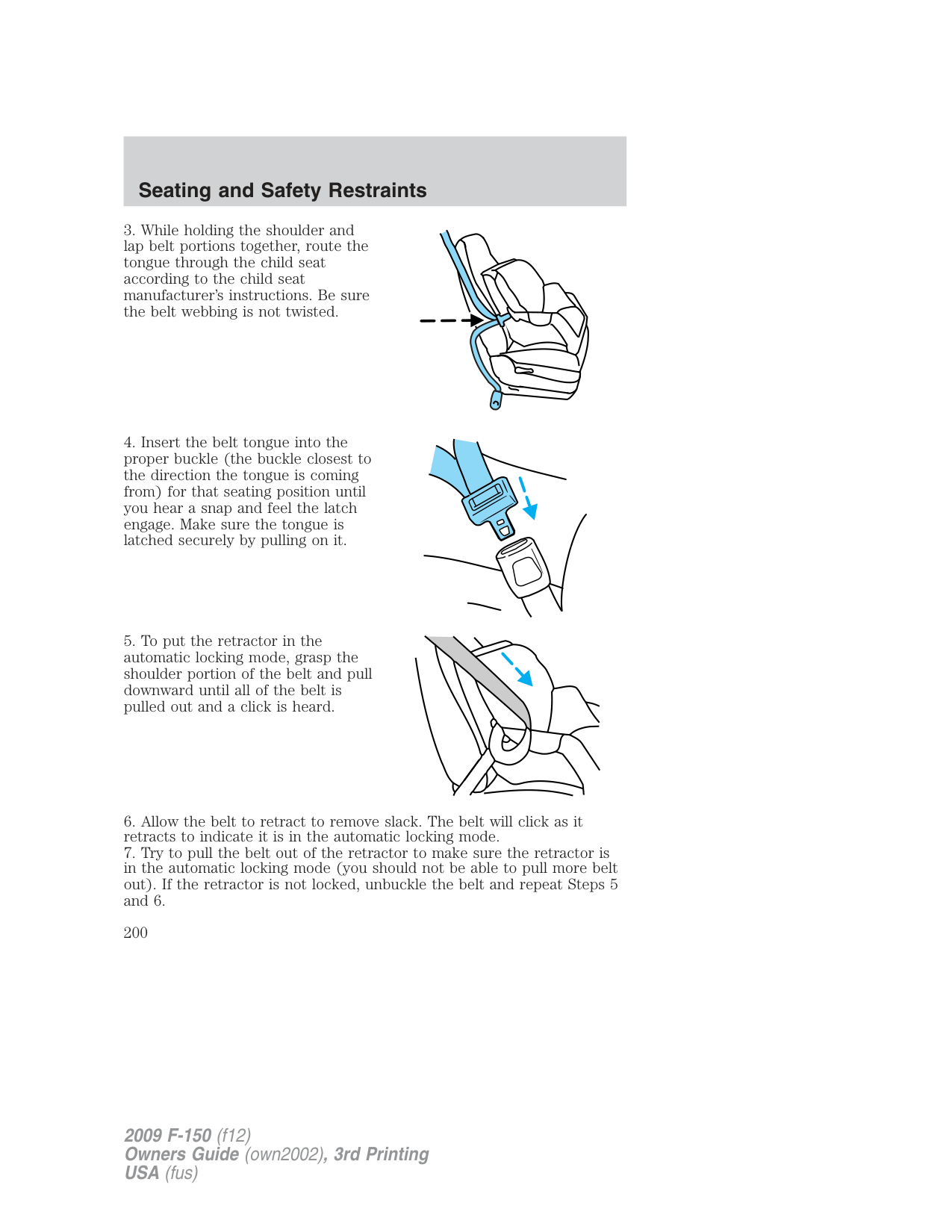
|Forward facing child seat|Up to 48 lb (21 kg)|X| |X| |X| |Forward facing child seat|Over 48 lb (21 kg)| | |X|X| |
XX
WARNING: Air bags can kill or injure a child in a child seat. NEVER place a rear-facing child seat in front of an active air
bag. If you must use a forward-facing child seat in the front seat, move the vehicle seat all the way back. When possible, all children age 12 and under should be properly restrained in a rear seating position. If all children cannot be seated and restrained properly in a rear seating position, properly restrain the largest child in the front seat.
WARNING: Always carefully follow the instructions and warnings provided by the manufacturer of any child restraint to
determine if the restraint device is appropriate for your child’s size, height, weight, or age. Follow the child restraint manufacturer’s instructions and warnings provided for installation and use in conjunction with the instructions and warnings provided by the vehicle manufacturer. A safety seat that is improperly installed or utilized, is inappropriate for your child’s height, age, or weight or does not properly fit the child may increase the risk of serious injury or death.
WARNING: Never let a passenger hold a child on his or her lap while the vehicle is moving. The passenger cannot protect the
child from injury in a collision, which may result in serious injury or death.
WARNING: Never use pillows, books, or towels to boost a child. They can slide around and increase the likelihood of injury or
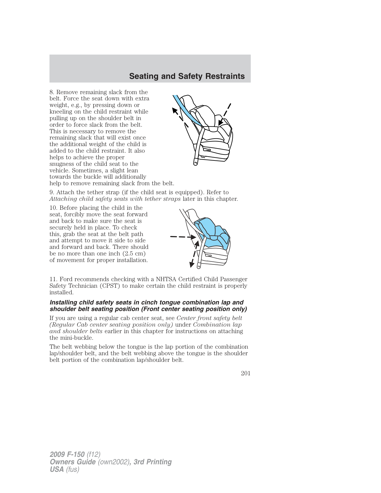
death in a collision.
WARNING: Always restrain an unoccupied child seat or booster seat. These objects may become projectiles in a collision or
sudden stop, which may increase the risk of serious injury.
WARNING: Never place, or allow a child to place, the shoulder belt under a child’s arm or behind the back because it reduces
the protection for the upper part of the body and may increase the risk of injury or death in a collision.
WARNING: Do not leave children, unreliable adults, or pets unattended in your vehicle.
###### Transporting children
Always make sure your child is secured properly in a device that is appropriate for their age, height and weight. All children are shaped differently. The child height, age and weight thresholds provided are recommendations or the minimum requirements of law. The National Highway Traffic Safety Administration (NHTSA) provides education and training to ensure that all children ages 0 to 16 are properly restrained in the correct restraint system. Ford recommends checking with a NHTSA Certified Child Passenger Safety Technician (CPST) and your pediatrician to make sure your seat is appropriate for your child and properly installed in the vehicle. To locate a child seat fitting station and CPST contact the NHTSA toll free at 1-888-327-4236 or on the internet at http://www.nhtsa.dot.gov.
Follow all the safety restraint and airbag precautions that apply to adult passengers in your vehicle.
If the child is the proper height, age, and weight (as specified by your child safety seat or booster manufacturer), fits the restraint and can be restrained properly, then restrain the child in the child safety seat or with the belt-positioning booster. Remember that child seats and belt-positioning boosters vary and may be designed to fit children of different heights, ages and weights. Children who are too large for child safety seats or belt-positioning boosters (as specified by your child safety seat manufacturer) should always properly wear safety belts.
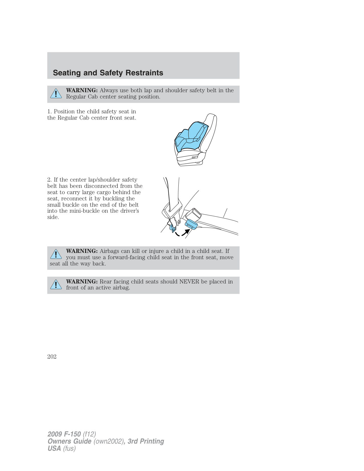
SAFETY SEATS FOR CHILDREN Infant and/or toddler seats
Use a safety seat that is recommended for the size and weight of the child.
When installing a child safety seat:
Airbags can kill or injure a child in a child seat. NEVER place a rear-facing child seat in front of an active airbag. If you must use a forward-facing child seat in the front seat, move the vehicle seat all the way back.
Children 12 and under should be properly restrained in a rear seating position whenever possible. If all children cannot be seated and restrained properly in a rear seating position, properly restrain the largest child in the front seat.
Installing child safety seats with combination lap and shoulder belts
Check to make sure the child seat is properly secured before each use. Children 12 and under should be properly restrained in a rear seating position whenever possible. If all children cannot be seated and restrained properly in a rear seating position, properly restrain the largest child in the front seat.
When installing a child safety seat with combination lap/shoulder belts:
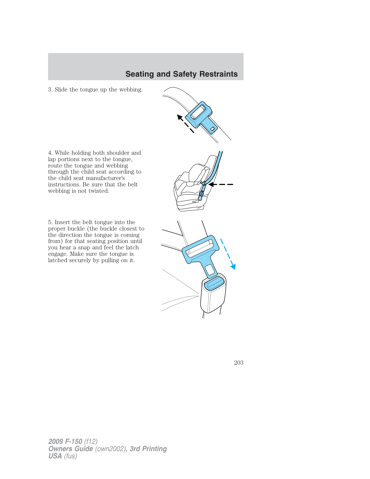
WARNING: Depending on where you secure a child restraint, and depending on the child restraint design, you may block
access to certain safety belt buckle assemblies and/or LATCH lower anchors, rendering those features potentially unusable. To avoid risk of injury, occupants should only use seating positions where they are able to be properly restrained.
If you are using a Regular Cab center seat, see Installing child safety seats in cinch tongue combination lap and shoulder belt seating position later in this chapter for instructions.
Perform the following steps when installing the child seat with combination lap/shoulder belts:
Note: Although the child seat illustrated is a forward facing child seat, the steps are the same for installing a rear facing child seat.
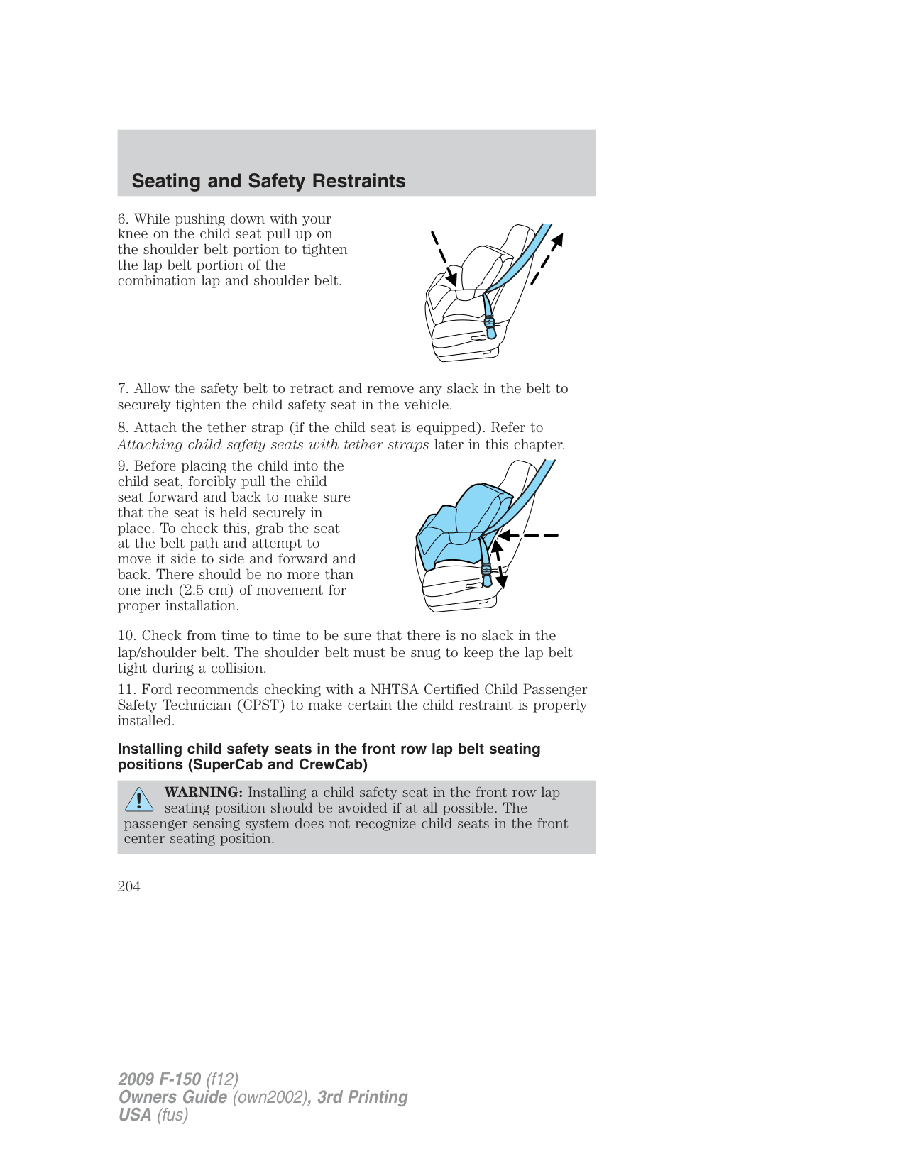
Installing child safety seats in cinch tongue combination lap and shoulder belt seating position (Front center seating position only)
If you are using a regular cab center seat, see Center front safety belt (Regular Cab center seating position only) under Combination lap and shoulder belts earlier in this chapter for instructions on attaching the mini-buckle.
The belt webbing below the tongue is the lap portion of the combination lap/shoulder belt, and the belt webbing above the tongue is the shoulder belt portion of the combination lap/shoulder belt.
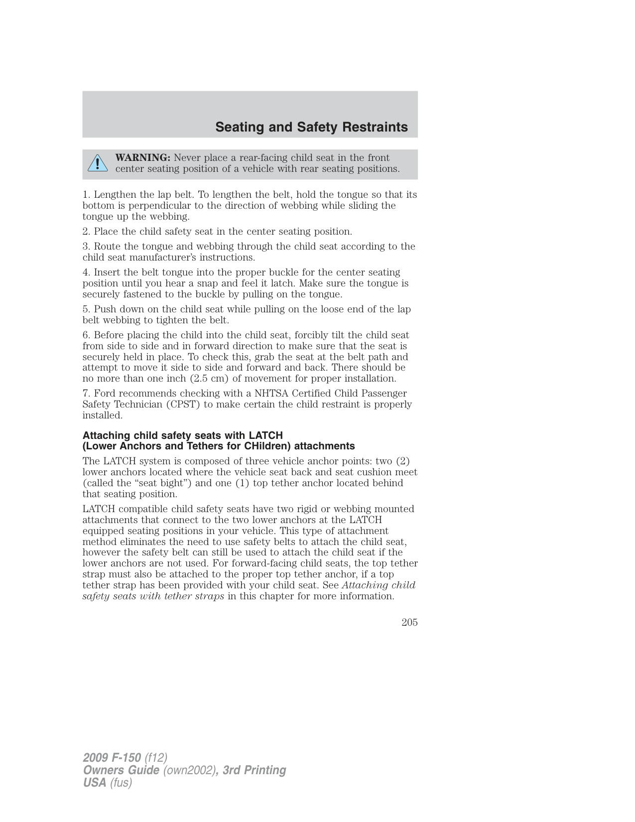
WARNING: Always use both lap and shoulder safety belt in the Regular Cab center seating position.
WARNING: Airbags can kill or injure a child in a child seat. If you must use a forward-facing child seat in the front seat, move
seat all the way back.
WARNING: Rear facing child seats should NEVER be placed in front of an active airbag.
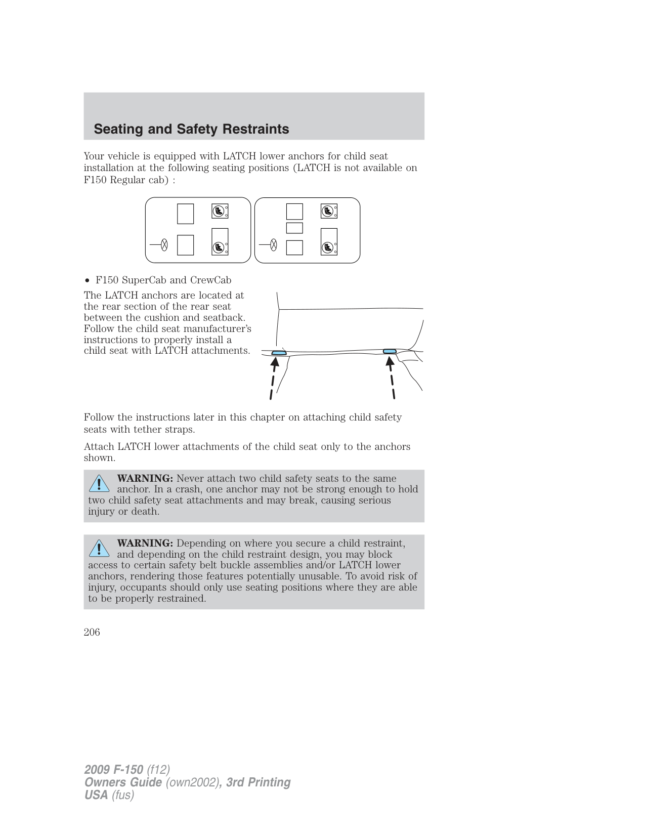
Installing child safety seats in the front row lap belt seating positions (SuperCab and CrewCab)
WARNING: Installing a child safety seat in the front row lap seating position should be avoided if at all possible. The passenger sensing system does not recognize child seats in the front center seating position.
WARNING: Never place a rear-facing child seat in the front center seating position of a vehicle with rear seating positions.
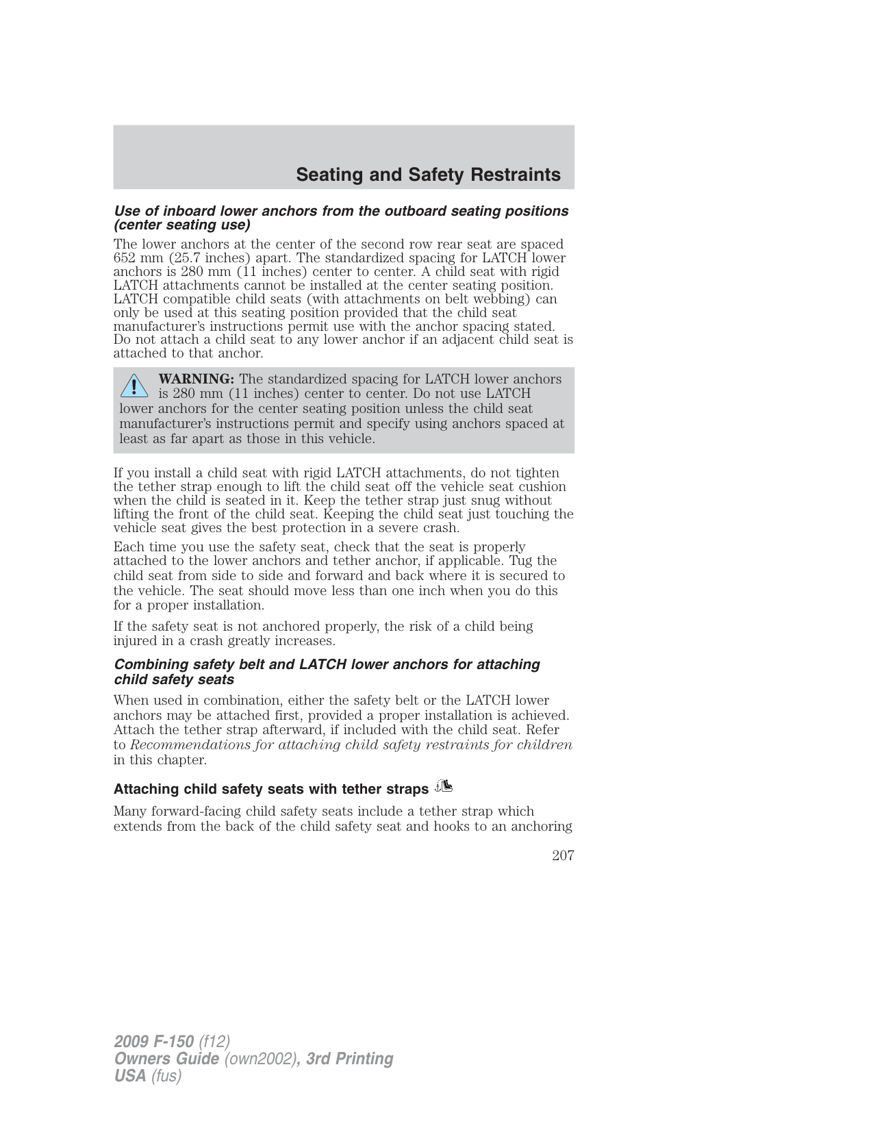
Attaching child safety seats with LATCH (Lower Anchors and Tethers for CHildren) attachments
The LATCH system is composed of three vehicle anchor points: two (2) lower anchors located where the vehicle seat back and seat cushion meet (called the “seat bight”) and one (1) top tether anchor located behind that seating position.
LATCH compatible child safety seats have two rigid or webbing mounted attachments that connect to the two lower anchors at the LATCH equipped seating positions in your vehicle. This type of attachment method eliminates the need to use safety belts to attach the child seat, however the safety belt can still be used to attach the child seat if the lower anchors are not used. For forward-facing child seats, the top tether strap must also be attached to the proper top tether anchor, if a top tether strap has been provided with your child seat. See Attaching child safety seats with tether straps in this chapter for more information.
Your vehicle is equipped with LATCH lower anchors for child seat installation at the following seating positions (LATCH is not available on F150 Regular cab) :
• F150 SuperCab and CrewCab
The LATCH anchors are located at the rear section of the rear seat between the cushion and seatback. Follow the child seat manufacturer’s instructions to properly install a child seat with LATCH attachments.
Follow the instructions later in this chapter on attaching child safety seats with tether straps.
Attach LATCH lower attachments of the child seat only to the anchors shown.
WARNING: Never attach two child safety seats to the same anchor. In a crash, one anchor may not be strong enough to hold
two child safety seat attachments and may break, causing serious injury or death.
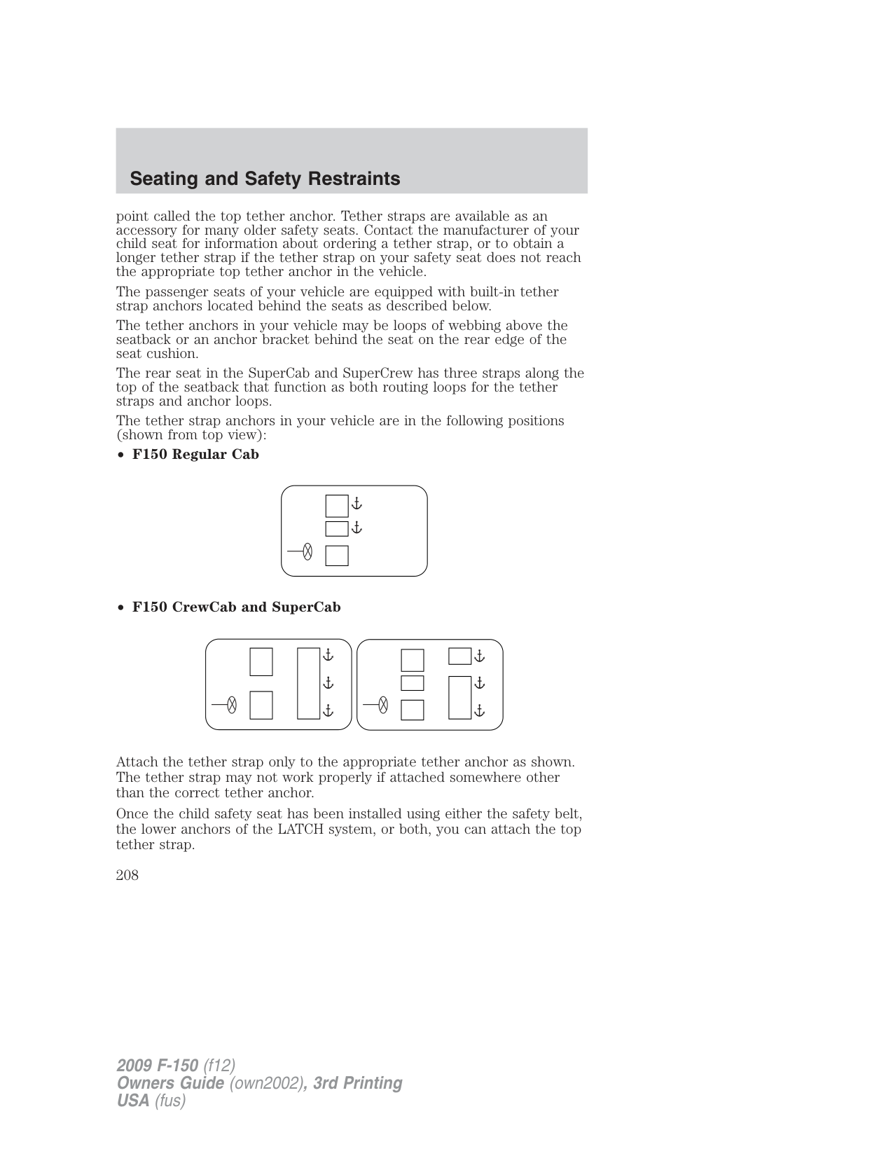
WARNING: Depending on where you secure a child restraint, and depending on the child restraint design, you may block
access to certain safety belt buckle assemblies and/or LATCH lower anchors, rendering those features potentially unusable. To avoid risk of injury, occupants should only use seating positions where they are able to be properly restrained.
Use of inboard lower anchors from the outboard seating positions (center seating use)
The lower anchors at the center of the second row rear seat are spaced 652 mm (25.7 inches) apart. The standardized spacing for LATCH lower anchors is 280 mm (11 inches) center to center. A child seat with rigid LATCH attachments cannot be installed at the center seating position. LATCH compatible child seats (with attachments on belt webbing) can only be used at this seating position provided that the child seat manufacturer’s instructions permit use with the anchor spacing stated. Do not attach a child seat to any lower anchor if an adjacent child seat is attached to that anchor.
WARNING: The standardized spacing for LATCH lower anchors is 280 mm (11 inches) center to center. Do not use LATCH
lower anchors for the center seating position unless the child seat manufacturer’s instructions permit and specify using anchors spaced at least as far apart as those in this vehicle.
If you install a child seat with rigid LATCH attachments, do not tighten the tether strap enough to lift the child seat off the vehicle seat cushion when the child is seated in it. Keep the tether strap just snug without lifting the front of the child seat. Keeping the child seat just touching the vehicle seat gives the best protection in a severe crash.
Each time you use the safety seat, check that the seat is properly attached to the lower anchors and tether anchor, if applicable. Tug the child seat from side to side and forward and back where it is secured to the vehicle. The seat should move less than one inch when you do this for a proper installation.
If the safety seat is not anchored properly, the risk of a child being injured in a crash greatly increases.
Combining safety belt and LATCH lower anchors for attaching child safety seats
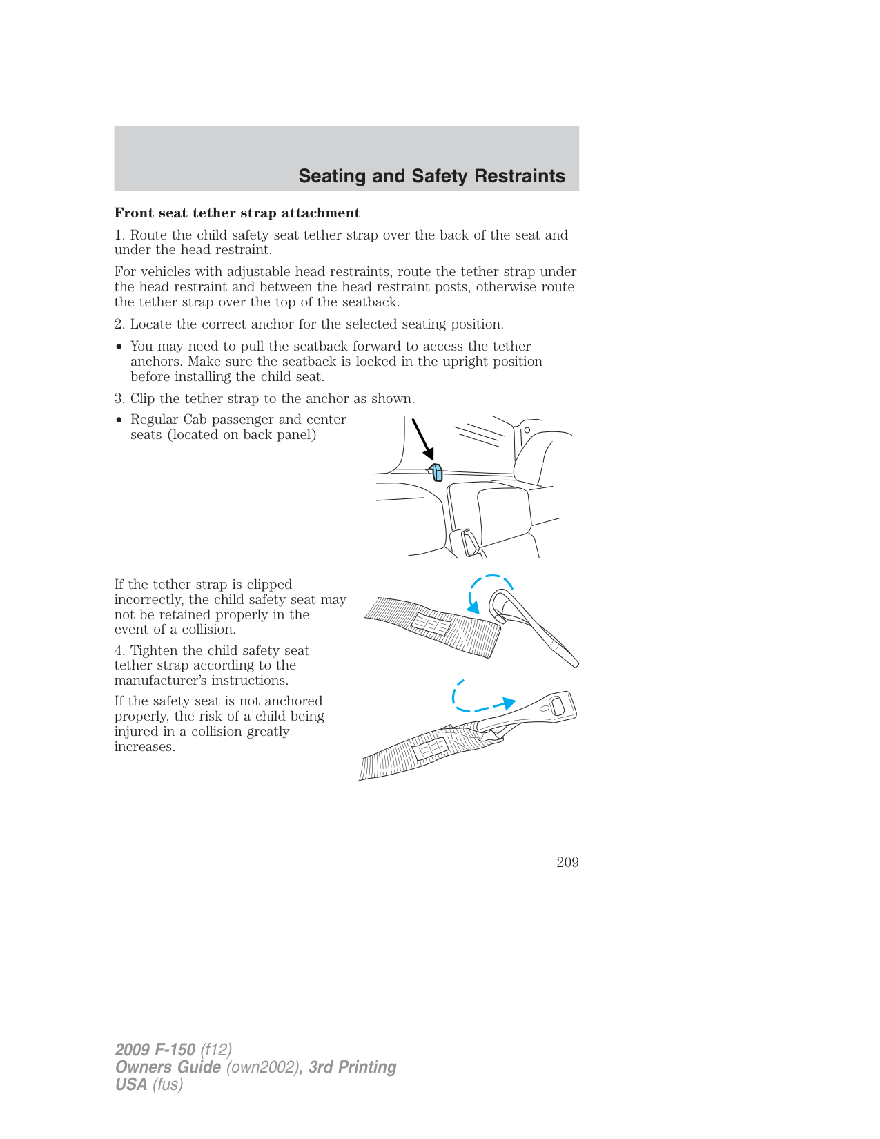
When used in combination, either the safety belt or the LATCH lower anchors may be attached first, provided a proper installation is achieved. Attach the tether strap afterward, if included with the child seat. Refer to Recommendations for attaching child safety restraints for children in this chapter.
###### Attaching child safety seats with tether straps
Many forward-facing child safety seats include a tether strap which extends from the back of the child safety seat and hooks to an anchoring
point called the top tether anchor. Tether straps are available as an accessory for many older safety seats. Contact the manufacturer of your child seat for information about ordering a tether strap, or to obtain a longer tether strap if the tether strap on your safety seat does not reach the appropriate top tether anchor in the vehicle.
The passenger seats of your vehicle are equipped with built-in tether strap anchors located behind the seats as described below.
The tether anchors in your vehicle may be loops of webbing above the seatback or an anchor bracket behind the seat on the rear edge of the seat cushion.
The rear seat in the SuperCab and SuperCrew has three straps along the top of the seatback that function as both routing loops for the tether straps and anchor loops.
The tether strap anchors in your vehicle are in the following positions (shown from top view):
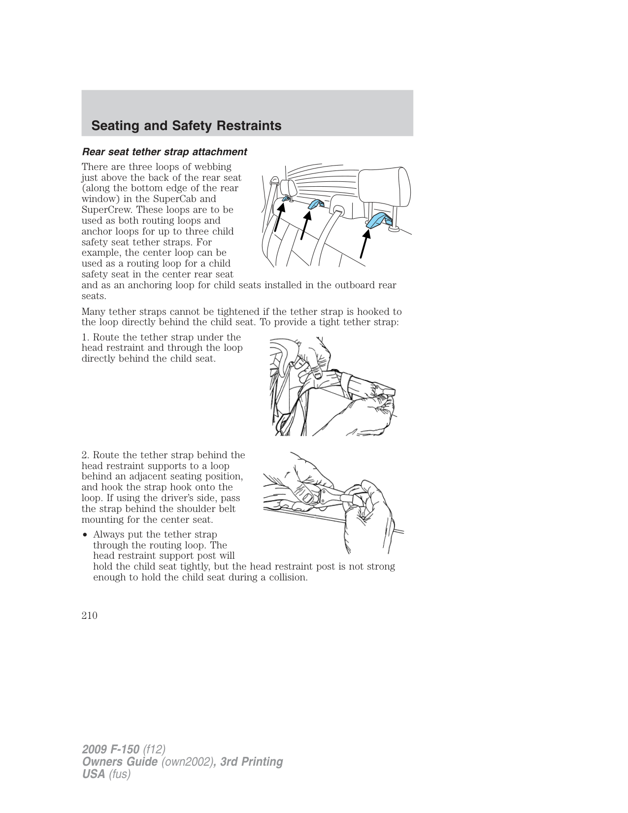
Attach the tether strap only to the appropriate tether anchor as shown. The tether strap may not work properly if attached somewhere other than the correct tether anchor.
Once the child safety seat has been installed using either the safety belt, the lower anchors of the LATCH system, or both, you can attach the top tether strap.
###### Front seat tether strap attachment
For vehicles with adjustable head restraints, route the tether strap under the head restraint and between the head restraint posts, otherwise route the tether strap over the top of the seatback.
• You may need to pull the seatback forward to access the tether anchors. Make sure the seatback is locked in the upright position before installing the child seat.
• Regular Cab passenger and center
seats (located on back panel)
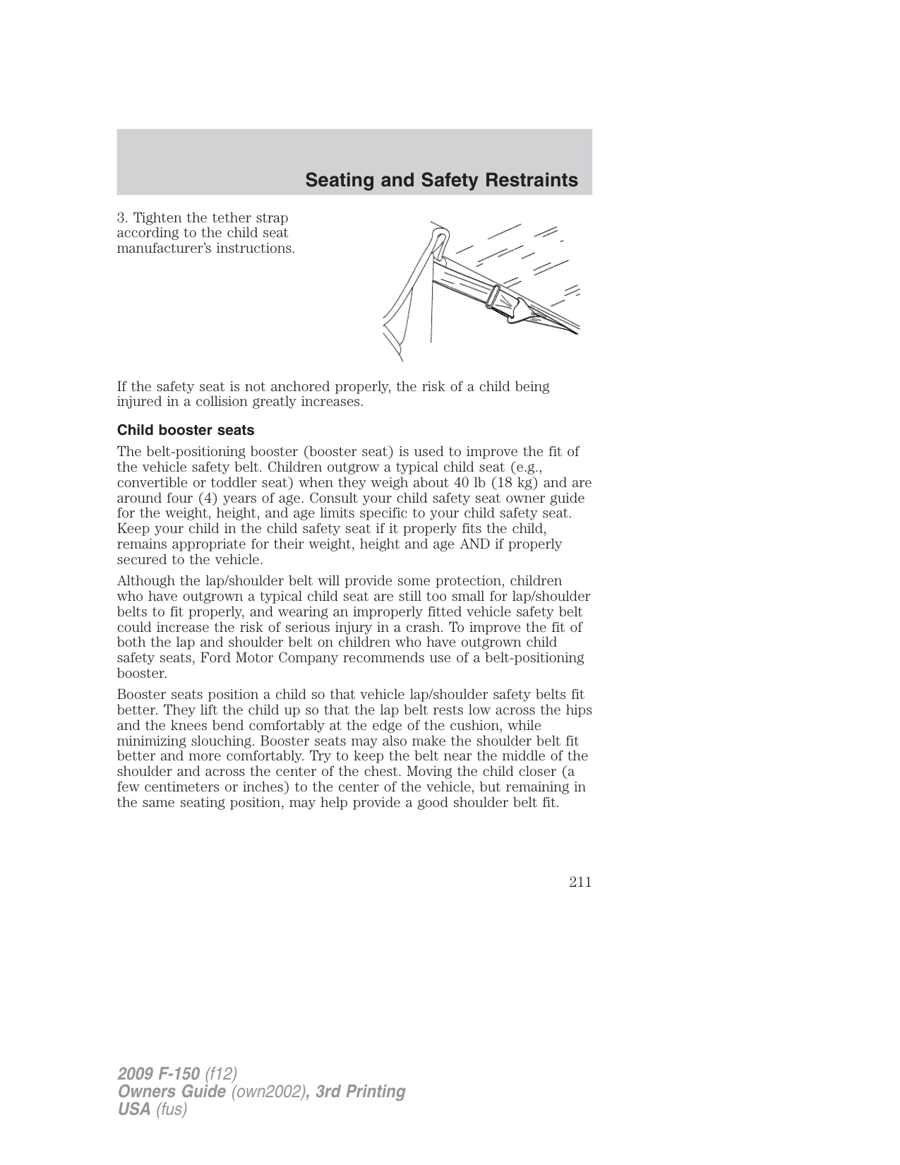
If the tether strap is clipped incorrectly, the child safety seat may not be retained properly in the event of a collision.
If the safety seat is not anchored properly, the risk of a child being injured in a collision greatly increases.
###### Rear seat tether strap attachment
There are three loops of webbing just above the back of the rear seat (along the bottom edge of the rear window) in the SuperCab and SuperCrew. These loops are to be used as both routing loops and anchor loops for up to three child safety seat tether straps. For example, the center loop can be used as a routing loop for a child safety seat in the center rear seat and as an anchoring loop for child seats installed in the outboard rear seats.
Many tether straps cannot be tightened if the tether strap is hooked to the loop directly behind the child seat. To provide a tight tether strap:


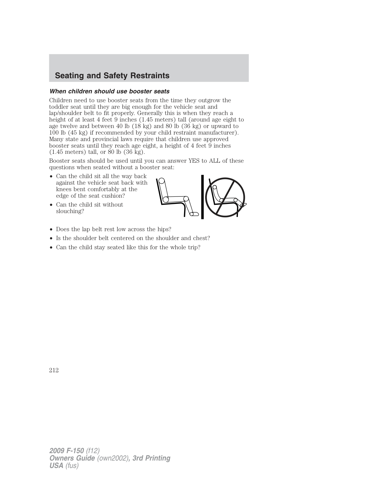
• Always put the tether strap through the routing loop. The head restraint support post will hold the child seat tightly, but the head restraint post is not strong enough to hold the child seat during a collision.

If the safety seat is not anchored properly, the risk of a child being injured in a collision greatly increases.
###### Child booster seats
The belt-positioning booster (booster seat) is used to improve the fit of the vehicle safety belt. Children outgrow a typical child seat (e.g., convertible or toddler seat) when they weigh about 40 lb (18 kg) and are around four (4) years of age. Consult your child safety seat owner guide for the weight, height, and age limits specific to your child safety seat. Keep your child in the child safety seat if it properly fits the child, remains appropriate for their weight, height and age AND if properly secured to the vehicle.
Although the lap/shoulder belt will provide some protection, children who have outgrown a typical child seat are still too small for lap/shoulder belts to fit properly, and wearing an improperly fitted vehicle safety belt could increase the risk of serious injury in a crash. To improve the fit of both the lap and shoulder belt on children who have outgrown child safety seats, Ford Motor Company recommends use of a belt-positioning booster.
Booster seats position a child so that vehicle lap/shoulder safety belts fit better. They lift the child up so that the lap belt rests low across the hips and the knees bend comfortably at the edge of the cushion, while minimizing slouching. Booster seats may also make the shoulder belt fit better and more comfortably. Try to keep the belt near the middle of the shoulder and across the center of the chest. Moving the child closer (a few centimeters or inches) to the center of the vehicle, but remaining in the same seating position, may help provide a good shoulder belt fit.
###### When children should use booster seats
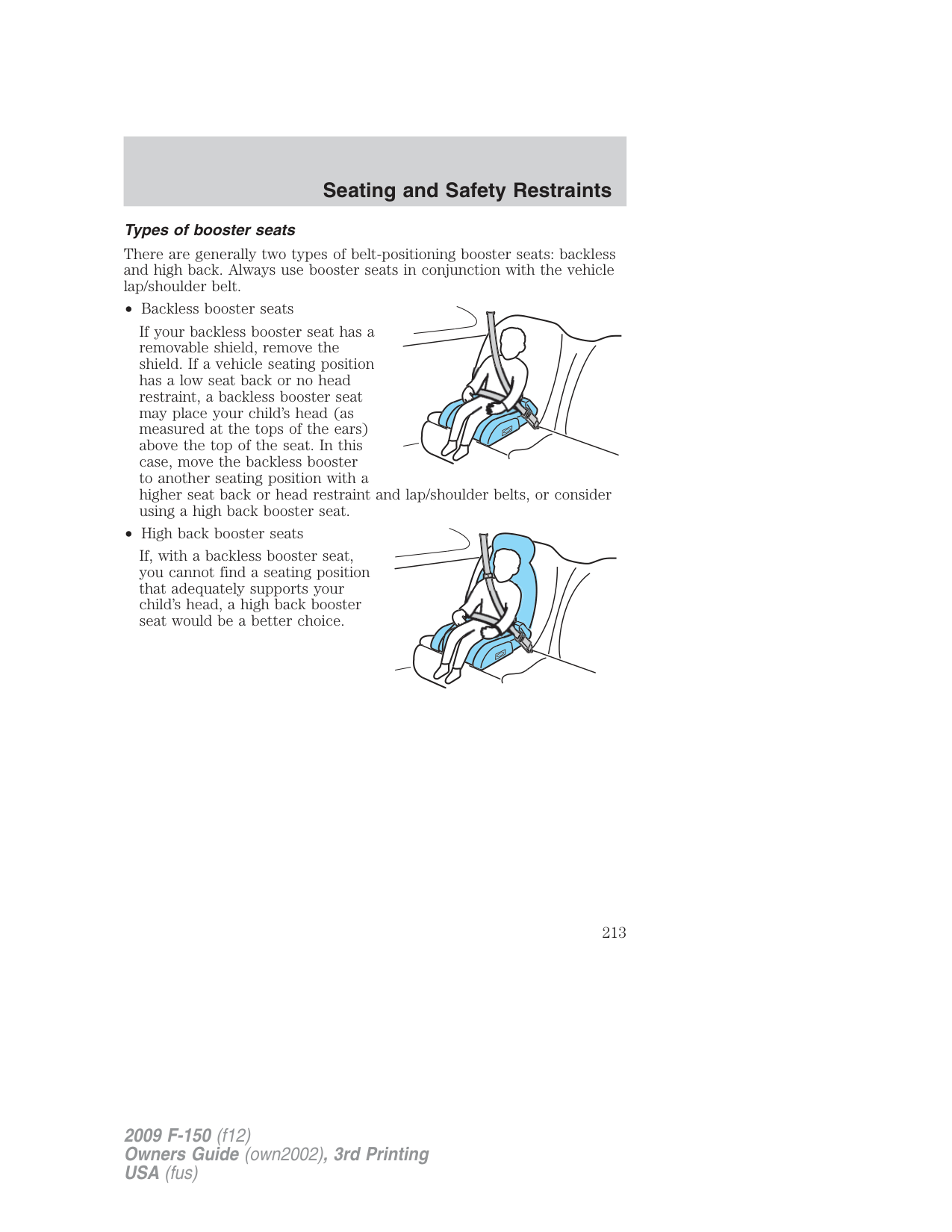
Children need to use booster seats from the time they outgrow the toddler seat until they are big enough for the vehicle seat and lap/shoulder belt to fit properly. Generally this is when they reach a height of at least 4 feet 9 inches (1.45 meters) tall (around age eight to age twelve and between 40 lb (18 kg) and 80 lb (36 kg) or upward to 100 lb (45 kg) if recommended by your child restraint manufacturer). Many state and provincial laws require that children use approved booster seats until they reach age eight, a height of 4 feet 9 inches (1.45 meters) tall, or 80 lb (36 kg).
Booster seats should be used until you can answer YES to ALL of these questions when seated without a booster seat:
###### Types of booster seats
There are generally two types of belt-positioning booster seats: backless and high back. Always use booster seats in conjunction with the vehicle lap/shoulder belt.
If your backless booster seat has a removable shield, remove the shield. If a vehicle seating position has a low seat back or no head restraint, a backless booster seat may place your child’s head (as measured at the tops of the ears) above the top of the seat. In this case, move the backless booster to another seating position with a higher seat back or head restraint and lap/shoulder belts, or consider using a high back booster seat.
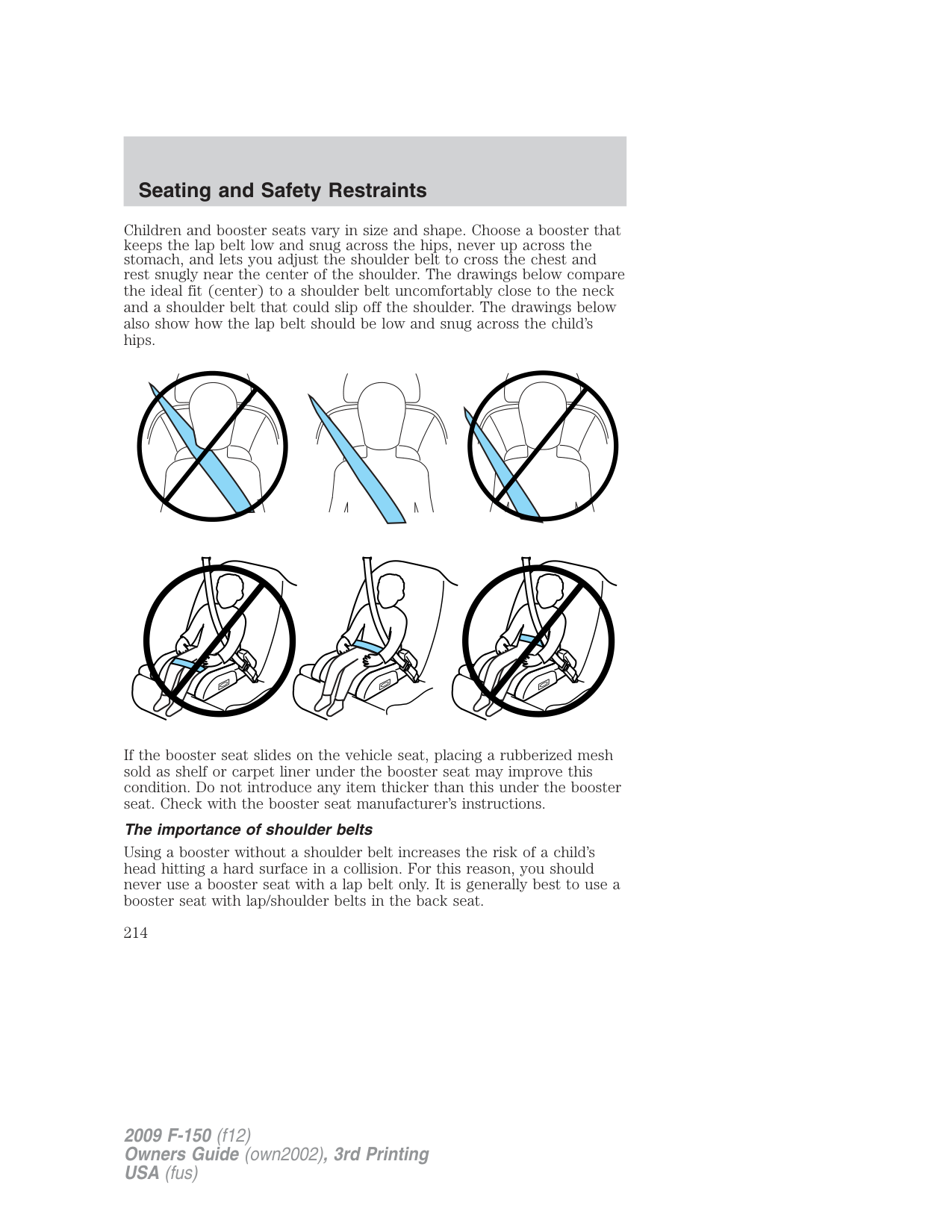

If, with a backless booster seat, you cannot find a seating position that adequately supports your child’s head, a high back booster seat would be a better choice.

Children and booster seats vary in size and shape. Choose a booster that keeps the lap belt low and snug across the hips, never up across the stomach, and lets you adjust the shoulder belt to cross the chest and rest snugly near the center of the shoulder. The drawings below compare
the ideal fit (center) to a shoulder belt uncomfortably close to the neck and a shoulder belt that could slip off the shoulder. The drawings below also show how the lap belt should be low and snug across the child’s hips.
If the booster seat slides on the vehicle seat, placing a rubberized mesh sold as shelf or carpet liner under the booster seat may improve this condition. Do not introduce any item thicker than this under the booster seat. Check with the booster seat manufacturer’s instructions.
###### The importance of shoulder belts
Using a booster without a shoulder belt increases the risk of a child’s head hitting a hard surface in a collision. For this reason, you should never use a booster seat with a lap belt only. It is generally best to use a booster seat with lap/shoulder belts in the back seat.
Move a child to a different seating location if the shoulder belt does not stay positioned on the shoulder during use.
Follow all instructions provided by the manufacturer of the booster seat.
WARNING: Never place, or allow a child to place, the shoulder belt under a child’s arm or behind the back because it reduces
the protection for the upper part of the body and may increase the risk of injury or death in a collision.
###### Child restraint and safety belt maintenance
Inspect the vehicle safety belts and child safety seat systems periodically to make sure they work properly and are not damaged. Inspect the vehicle and child seat safety belts to make sure there are no nicks, tears or cuts. Replace if necessary. All vehicle safety belt assemblies, including retractors, buckles, front safety belt buckle assemblies, buckle support assemblies (slide bar-if equipped), shoulder belt height adjusters (if equipped), shoulder belt guide on seatback (if equipped), child safety seat LATCH and tether anchors, and attaching hardware, should be inspected after a collision. Refer to the child restraint manufacturer’s instructions for additional inspection and maintenance information specific to the child restraint. Ford Motor Company recommends that all safety belt assemblies in use in vehicles involved in a collision be replaced. However, if the collision was minor and an authorized dealer finds that the belts do not show damage and continue to operate properly, they do not need to be replaced. Safety belt assemblies not in use during a collision should also be inspected and replaced if either damage or improper operation is noted.
For proper care of soiled safety belts, refer to Interior in the Cleaning chapter.
WARNING: Failure to inspect and if necessary replace the safety belt assembly or child restraint system under the above
conditions could result in severe personal injuries in the event of a collision.
###### NOTICE TO UTILITY VEHICLE AND TRUCK OWNERS
Utility vehicles and trucks handle differently than passenger cars in the various driving conditions that are encountered on streets, highways and off-road. Utility vehicles and trucks are not designed for cornering at speeds as high as passenger cars any more than low-slung sports cars are designed to perform satisfactorily under off-road conditions.
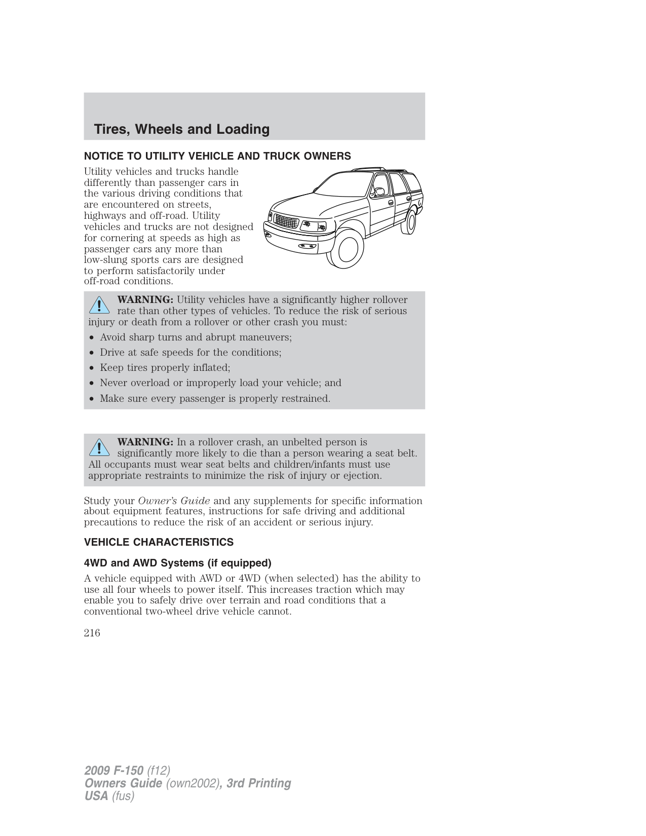
WARNING: Utility vehicles have a significantly higher rollover rate than other types of vehicles. To reduce the risk of serious
injury or death from a rollover or other crash you must:
WARNING: In a rollover crash, an unbelted person is significantly more likely to die than a person wearing a seat belt.
All occupants must wear seat belts and children/infants must use appropriate restraints to minimize the risk of injury or ejection.
Study your Owner’s Guide and any supplements for specific information about equipment features, instructions for safe driving and additional precautions to reduce the risk of an accident or serious injury.
VEHICLE CHARACTERISTICS 4WD and AWD Systems (if equipped)
A vehicle equipped with AWD or 4WD (when selected) has the ability to use all four wheels to power itself. This increases traction which may enable you to safely drive over terrain and road conditions that a conventional two-wheel drive vehicle cannot.
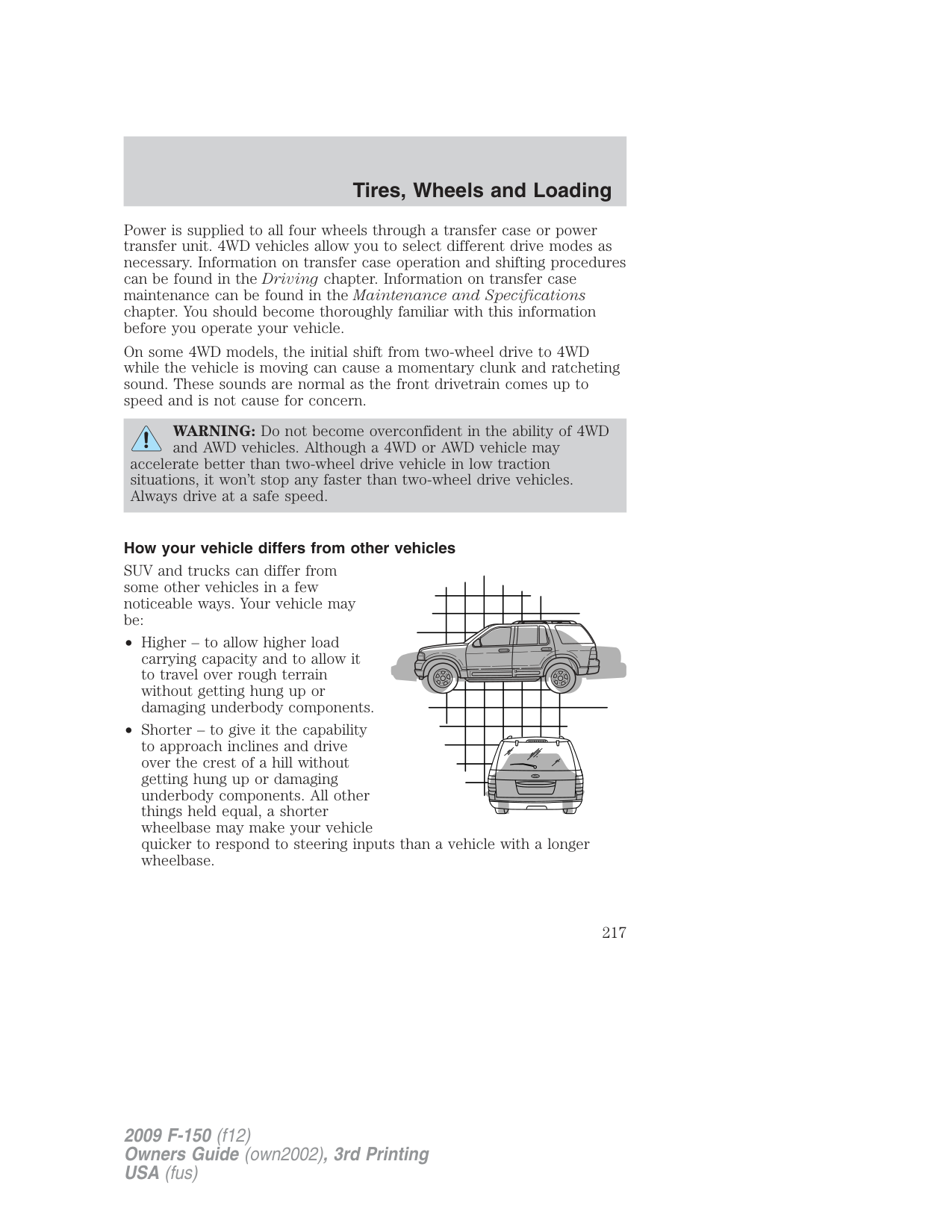
Power is supplied to all four wheels through a transfer case or power transfer unit. 4WD vehicles allow you to select different drive modes as necessary. Information on transfer case operation and shifting procedures can be found in the Driving chapter. Information on transfer case maintenance can be found in the Maintenance and Specifications chapter. You should become thoroughly familiar with this information before you operate your vehicle.
On some 4WD models, the initial shift from two-wheel drive to 4WD while the vehicle is moving can cause a momentary clunk and ratcheting sound. These sounds are normal as the front drivetrain comes up to speed and is not cause for concern.
WARNING: Do not become overconfident in the ability of 4WD and AWD vehicles. Although a 4WD or AWD vehicle may
accelerate better than two-wheel drive vehicle in low traction situations, it won’t stop any faster than two-wheel drive vehicles. Always drive at a safe speed.
###### How your vehicle differs from other vehicles
SUV and trucks can differ from some other vehicles in a few noticeable ways. Your vehicle may be:
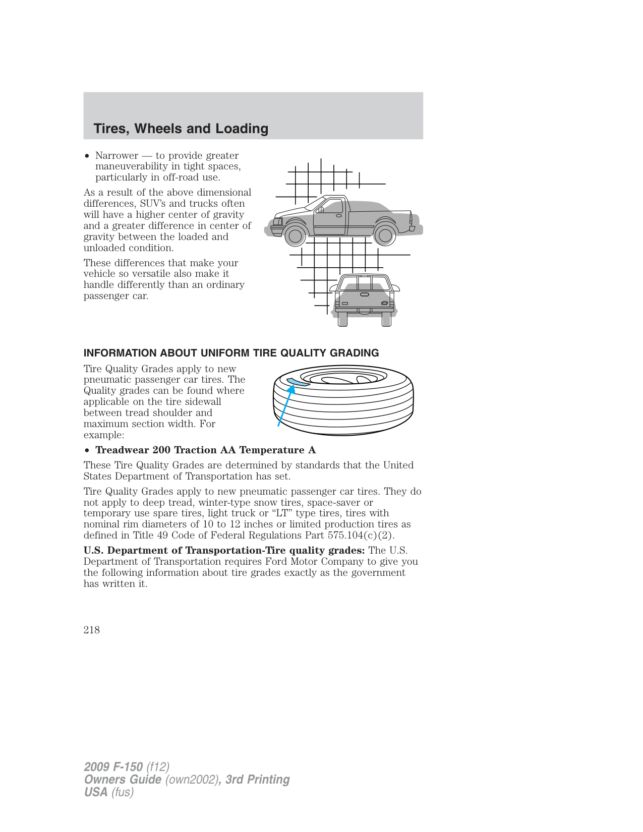
These differences that make your vehicle so versatile also make it handle differently than an ordinary passenger car.
| | | | | | | | | | |---|---|---|---|---|---|---|---|---| | | | | | | | | | | | | | | | | | | | |
###### INFORMATION ABOUT UNIFORM TIRE QUALITY GRADING
Tire Quality Grades apply to new pneumatic passenger car tires. The Quality grades can be found where applicable on the tire sidewall between tread shoulder and maximum section width. For example:
###### • Treadwear 200 Traction AA Temperature A
These Tire Quality Grades are determined by standards that the United States Department of Transportation has set.
Tire Quality Grades apply to new pneumatic passenger car tires. They do not apply to deep tread, winter-type snow tires, space-saver or temporary use spare tires, light truck or “LT” type tires, tires with nominal rim diameters of 10 to 12 inches or limited production tires as defined in Title 49 Code of Federal Regulations Part 575.104(c)(2).
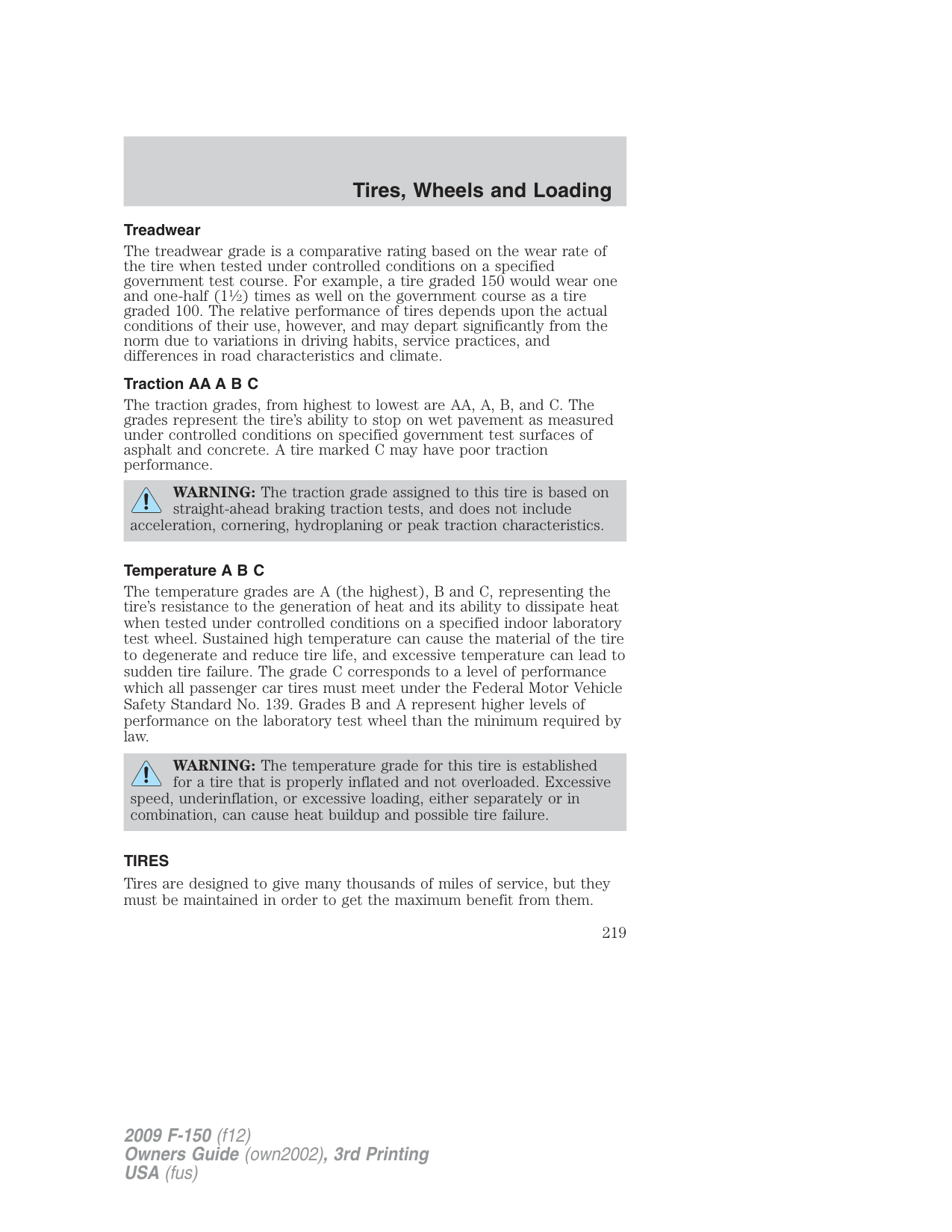
U.S. Department of Transportation-Tire quality grades: The U.S. Department of Transportation requires Ford Motor Company to give you the following information about tire grades exactly as the government has written it.
###### Treadwear
The treadwear grade is a comparative rating based on the wear rate of the tire when tested under controlled conditions on a specified government test course. For example, a tire graded 150 would wear one and one-half (11⁄2) times as well on the government course as a tire graded 100. The relative performance of tires depends upon the actual conditions of their use, however, and may depart significantly from the norm due to variations in driving habits, service practices, and differences in road characteristics and climate.
###### Traction AA A B C
The traction grades, from highest to lowest are AA, A, B, and C. The grades represent the tire’s ability to stop on wet pavement as measured under controlled conditions on specified government test surfaces of asphalt and concrete. A tire marked C may have poor traction performance.
WARNING: The traction grade assigned to this tire is based on straight-ahead braking traction tests, and does not include
acceleration, cornering, hydroplaning or peak traction characteristics.
Temperature A B C The temperature grades are A (the highest), B and C, representing the tire’s resistance to the generation of heat and its ability to dissipate heat when tested under controlled conditions on a specified indoor laboratory test wheel. Sustained high temperature can cause the material of the tire to degenerate and reduce tire life, and excessive temperature can lead to sudden tire failure. The grade C corresponds to a level of performance which all passenger car tires must meet under the Federal Motor Vehicle Safety Standard No. 139. Grades B and A represent higher levels of performance on the laboratory test wheel than the minimum required by law.
WARNING: The temperature grade for this tire is established for a tire that is properly inflated and not overloaded. Excessive
speed, underinflation, or excessive loading, either separately or in combination, can cause heat buildup and possible tire failure.
###### TIRES
Tires are designed to give many thousands of miles of service, but they must be maintained in order to get the maximum benefit from them.
###### Glossary of tire terminology
###### INFLATING YOUR TIRES
Safe operation of your vehicle requires that your tires are properly inflated. Remember that a tire can lose up to half of its air pressure without appearing flat.
Every day before you drive, check your tires. If one looks lower than the others, use a tire gauge to check pressure of all tires and adjust if required.
You are strongly urged to buy a reliable tire pressure gauge, as automatic service station gauges may be inaccurate. Ford recommends the use of a digital or dial-type tire pressure gauge rather than a stick-type tire pressure gauge.
Use the recommended cold inflation pressure for optimum tire performance and wear. Under-inflation or over-inflation may cause uneven treadwear patterns.
WARNING: Under-inflation is the most common cause of tire failures and may result in severe tire cracking, tread separation
or blowout , with unexpected loss of vehicle control and increased risk of injury. Under-inflation increases sidewall flexing and rolling resistance, resulting in heat buildup and internal damage to the tire. It also may result in unnecessary tire stress, irregular wear, loss of vehicle control and accidents. A tire can lose up to half of its air pressure and not appear to be flat!
Always inflate your tires to the Ford recommended inflation pressure even if it is less than the maximum inflation pressure information found on the tire. The Ford recommended tire inflation pressure is found on the Safety Compliance Certification Label or Tire Label which is located on the B-Pillar or the edge of the driver’s door. Failure to follow the tire pressure recommendations can cause uneven treadwear patterns and adversely affect the way your vehicle handles.
Maximum Permissible Inflation Pressure is the tire manufacturer’s maximum permissible pressure and/or the pressure at which the maximum load can be carried by the tire. This pressure is normally higher than the manufacturer’s recommended cold inflation pressure which can be found on the Safety Compliance Certification Label or Tire Label which is located on the B-Pillar or the edge of the driver’s door. The cold inflation pressure should never be set lower than the recommended pressure on the Safety Compliance Certification Label or Tire Label.
When weather temperature changes occur, tire inflation pressures also change. A 10°F (6°C) temperature drop can cause a corresponding drop of 1 psi (7 kPa) in inflation pressure. Check your tire pressures frequently and adjust them to the proper pressure which can be found on the Safety Compliance Certification Label or Tire Label. To check the pressure in your tire(s):
If you are checking tire pressure when the tire is hot, (i.e. driven more than 1 mile [1.6 km]), never “bleed” or reduce air pressure. The tires are hot from driving and it is normal for pressures to increase above recommended cold pressures. A hot tire at or below recommended cold inflation pressure could be significantly under-inflated.
Note: If you have to drive a distance to get air for your tire(s), check and record the tire pressure first and add the appropriate air pressure when you get to the pump. It is normal for tires to heat up and the air pressure inside to go up as you drive.
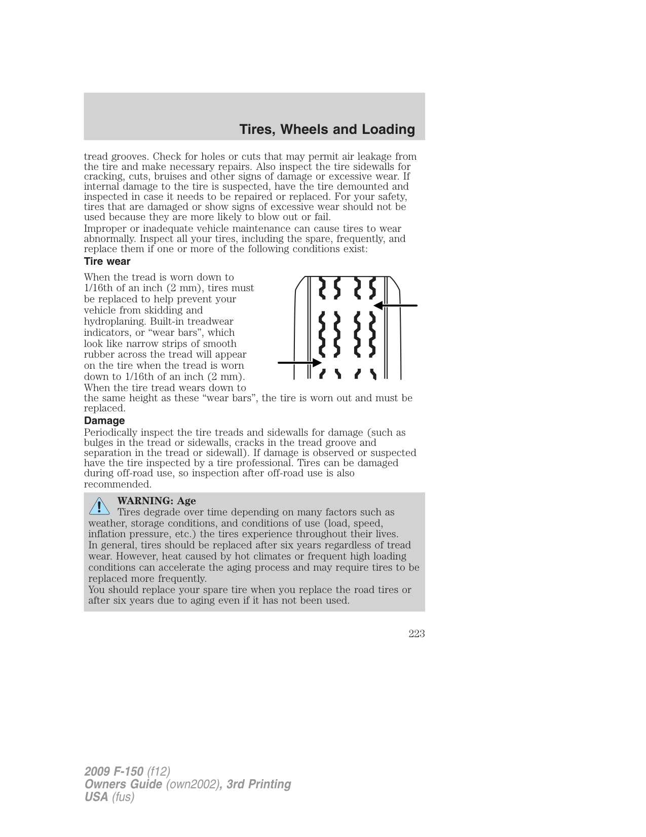
Inspecting your tires Periodically inspect the tire treads for uneven or excessive wear and remove objects such as stones, nails or glass that may be wedged in the
tread grooves. Check for holes or cuts that may permit air leakage from the tire and make necessary repairs. Also inspect the tire sidewalls for cracking, cuts, bruises and other signs of damage or excessive wear. If internal damage to the tire is suspected, have the tire demounted and inspected in case it needs to be repaired or replaced. For your safety, tires that are damaged or show signs of excessive wear should not be used because they are more likely to blow out or fail. Improper or inadequate vehicle maintenance can cause tires to wear abnormally. Inspect all your tires, including the spare, frequently, and replace them if one or more of the following conditions exist: Tire wear
When the tread is worn down to 1/16th of an inch (2 mm), tires must be replaced to help prevent your vehicle from skidding and hydroplaning. Built-in treadwear indicators, or “wear bars”, which look like narrow strips of smooth rubber across the tread will appear on the tire when the tread is worn down to 1/16th of an inch (2 mm). When the tire tread wears down to the same height as these “wear bars”, the tire is worn out and must be replaced. Damage Periodically inspect the tire treads and sidewalls for damage (such as bulges in the tread or sidewalls, cracks in the tread groove and separation in the tread or sidewall). If damage is observed or suspected have the tire inspected by a tire professional. Tires can be damaged during off-road use, so inspection after off-road use is also recommended.
| | | | |---|---|---| | | | | | | | |
WARNING: Age Tires degrade over time depending on many factors such as
weather, storage conditions, and conditions of use (load, speed, inflation pressure, etc.) the tires experience throughout their lives. In general, tires should be replaced after six years regardless of tread wear. However, heat caused by hot climates or frequent high loading conditions can accelerate the aging process and may require tires to be replaced more frequently. You should replace your spare tire when you replace the road tires or after six years due to aging even if it has not been used.
###### U.S. DOT Tire Identification Number (TIN)
Both U.S. and Canada Federal regulations require tire manufacturers to place standardized information on the sidewall of all tires. This information identifies and describes the fundamental characteristics of the tire and also provides a U.S. DOT Tire Identification Number for safety standard certification and in case of a recall.
This begins with the letters “DOT” and indicates that the tire meets all federal standards. The next two numbers or letters are the plant code designating where it was manufactured, the next two are the tire size code and the last four numbers represent the week and year the tire was built. For example, the numbers 317 mean the 31st week of 1997. After 2000 the numbers go to four digits. For example, 2501 means the 25th week of 2001. The numbers in between are identification codes used for traceability. This information is used to contact customers if a tire defect requires a recall.
###### Tire replacement requirements
Your vehicle is equipped with tires designed to provide a safe ride and handling capability.
WARNING: Only use replacement tires and wheels that are the same size, load index, speed rating and type (such as P-metric
versus LT-metric or all-season versus all-terrain) as those originally provided by Ford. The recommended tire and wheel size may be found on either the Safety Compliance Certification Label or the Tire Label which is located on the B-Pillar or edge of the driver’s door. If this information is not found on these labels then you should contact your authorized dealer as soon as possible. Use of any tire or wheel not recommended by Ford can affect the safety and performance of your vehicle, which could result in an increased risk of loss of vehicle control, vehicle rollover, personal injury and death. Additionally the use of non-recommended tires and wheels could cause steering, suspension, axle or transfer case/power transfer unit failure. If you have questions regarding tire replacement, contact your authorized dealer as soon as possible.
WARNING: When mounting replacement tires and wheels, you should not exceed the maximum pressure indicated on the
sidewall of the tire to set the beads without additional precautions listed below. If the beads do not seat at the maximum pressure indicated, re-lubricate and try again. When inflating the tire for mounting pressures up to 20 psi (1.38 bar) greater than the maximum pressure on the tire sidewall, the following precautions must be taken to protect the person mounting the tire:
Important: Remember to replace the wheel valve stems when the road tires are replaced on your vehicle. It is recommended that the two front tires or two rear tires generally be replaced as a pair. The tire pressure sensors mounted in the wheels (originally installed on your vehicle) are not designed to be used in aftermarket wheels. The use of wheels or tires not recommended by Ford Motor Company may affect the operation of your Tire Pressure Monitoring System. If the TPMS indicator is flashing, your TPMS is malfunctioning. Your replacement tire might be incompatible with your TPMS, or some component of the TPMS may be damaged.
Safety practices Driving habits have a great deal to do with your tire mileage and safety.
WARNING: If your vehicle is stuck in snow, mud, sand, etc., do not rapidly spin the tires; spinning the tires can tear the tire and
cause an explosion. A tire can explode in as little as three to five seconds.
WARNING: Do not spin the wheels at over 35 mph (56 km/h). The tires may fail and injure a passenger or bystander.
###### Highway hazards
No matter how carefully you drive there’s always the possibility that you may eventually have a flat tire on the highway. Drive slowly to the closest safe area out of traffic. This may further damage the flat tire, but your safety is more important.
If you feel a sudden vibration or ride disturbance while driving, or you suspect your tire or vehicle has been damaged, immediately reduce your speed. Drive with caution until you can safely pull off the road. Stop and inspect the tires for damage. If a tire is under-inflated or damaged, deflate it, remove wheel and replace it with your spare tire and wheel. If you cannot detect a cause, have the vehicle towed to the nearest repair facility or tire dealer to have the vehicle inspected.
###### Tire and wheel alignment
A bad jolt from hitting a curb or pothole can cause the front end of your vehicle to become misaligned or cause damage to your tires. If your vehicle seems to pull to one side when you’re driving, the wheels may be out of alignment. Have an authorized dealer check the wheel alignment periodically.
Wheel misalignment in the front or the rear can cause uneven and rapid treadwear of your tires and should be corrected by an authorized dealer. Front wheel drive (FWD) vehicles and those with an independent rear
suspension (if equipped) may require alignment of all four wheels. The tires should also be balanced periodically. An unbalanced tire and wheel assembly may result in irregular tire wear.
Tire rotation Rotating your tires at the recommended interval (as indicated in the scheduled maintenance information that comes with your vehicle) will help your tires wear more evenly, providing better tire performance and longer tire life.
• Rear Wheel Drive (RWD) vehicles/Four Wheel Drive (4WD)/ All Wheel Drive (AWD) vehicles (front tires at top of diagram)
Sometimes irregular tire wear can be corrected by rotating the tires. Note: If your tires show uneven wear ask an authorized dealer to check for and correct any wheel misalignment, tire imbalance or mechanical problem involved before tire rotation. Note: Your vehicle may be equipped with a dissimilar spare tire/wheel. A dissimilar spare tire/wheel is defined as a spare tire and/or wheel that is different in brand, size or appearance from the road tires and wheels. If you have a dissimilar spare tire/wheel it is intended for temporary use only and should not be used in a tire rotation. Note: After having your tires rotated, check tire pressure and adjust to the recommended inflation pressure. Note: The TPMS reset tool is ONLY provided for vehicles with different front and rear tire pressures. The TPMS reset procedure needs to be performed after tire rotation only on these vehicles.
WARNING: If the tire label shows different tire pressures for the front and rear tires and the vehicle is equipped with TPMS
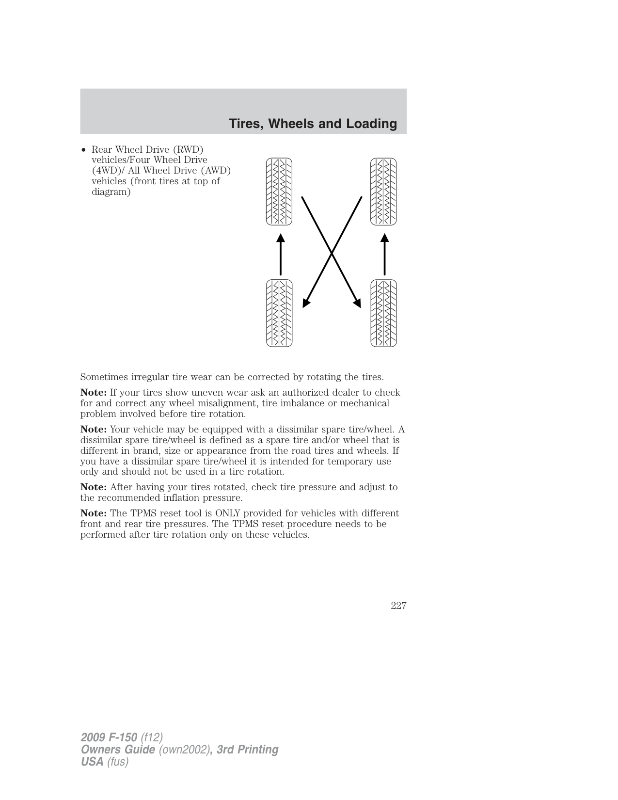
(tire pressure monitoring system), then the TPMS sensors need to be reset after tire rotation. If the system is not reset, it may not provide a low tire pressure warning when necessary. See the TPMS reset procedure in this chapter.
###### INFORMATION CONTAINED ON THE TIRE SIDEWALL
Both U.S. and Canada Federal regulations require tire manufacturers to place standardized information on the sidewall of all tires. This information identifies and describes the fundamental characteristics of the tire and also provides a U.S. DOT Tire Identification Number for safety standard certification and in case of a recall.
###### Information on “P” type tires
P215/65R15 95H is an example of a tire size, load index and speed rating. The definitions of these items are listed below. (Note that the tire size, load index and speed rating for your vehicle may be different from this example.)

Note: If your tire size does not begin with a letter this may mean it is designated by either ETRTO (European Tire and Rim Technical Organization) or JATMA (Japan Tire Manufacturing Association).
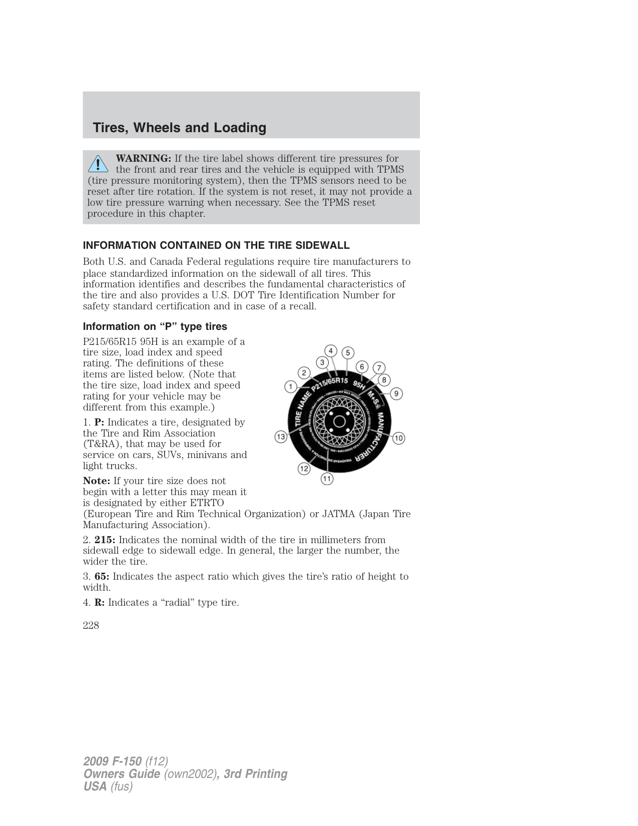
Note: You may not find this information on all tires because it is not required by federal law.
Note: You may not find this information on all tires because it is not required by federal law.
|Letter rating|Speed rating - mph (km/h)| |---|---| |M|81 mph (130 km/h)| |N|87 mph (140 km/h)| |Q|99 mph (159 km/h)| |R|106 mph (171 km/h)| |S|112 mph (180 km/h)| |T|118 mph (190 km/h)| |U|124 mph (200 km/h)|
|H|130 mph (210 km/h)| |V|149 mph (240 km/h)| |W|168 mph (270 km/h)| |Y|186 mph (299 km/h)| |Note: For tires with a maximum speed capability over 149 mph (240 km/h), tire manufacturers sometimes use the letters ZR. For those with a maximum speed capability over 186 mph (299 km/h), tire manufacturers always use the letters ZR.|Note: For tires with a maximum speed capability over 149 mph (240 km/h), tire manufacturers sometimes use the letters ZR. For those with a maximum speed capability over 186 mph (299 km/h), tire manufacturers always use the letters ZR.|
The tire suppliers may have additional markings, notes or warnings such as standard load, radial tubeless, etc.
Additional information contained on the tire sidewall for “LT” type tires
“LT” type tires have some additional information beyond those of “P” type tires; these differences are described below.

Note: Tire Quality Grades do not apply to this type of tire.
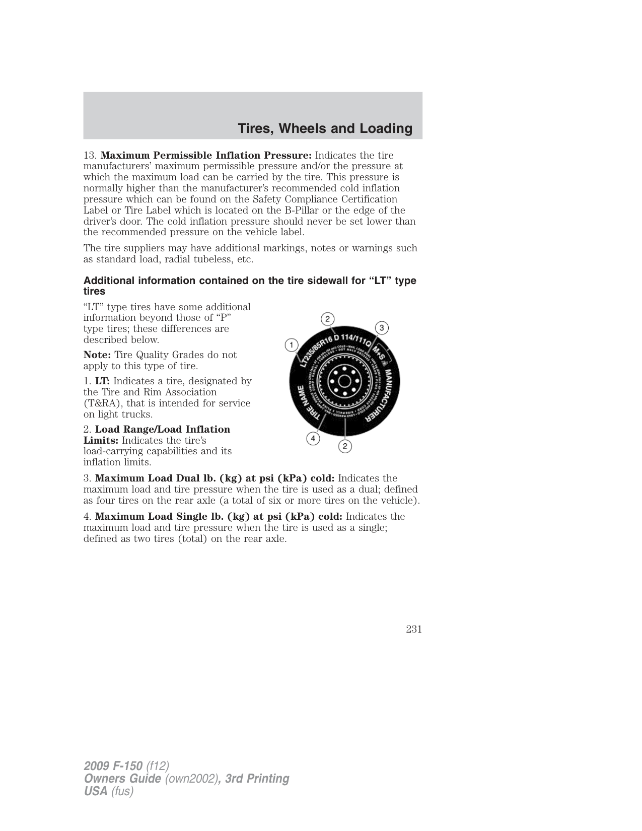
###### Information on “T” type tires
“T” type tires have some additional information beyond those of “P” type tires; these differences are described below:
T145/80D16 is an example of a tire size.
Note: The temporary tire size for your vehicle may be different from this example. Tire Quality Grades do not apply to this type of tire.
###### Location of the tire label
You will find a Tire Label containing tire inflation pressure by tire size and other important information located on the B-Pillar or the edge of the driver’s door. Refer to the payload description and graphic in the
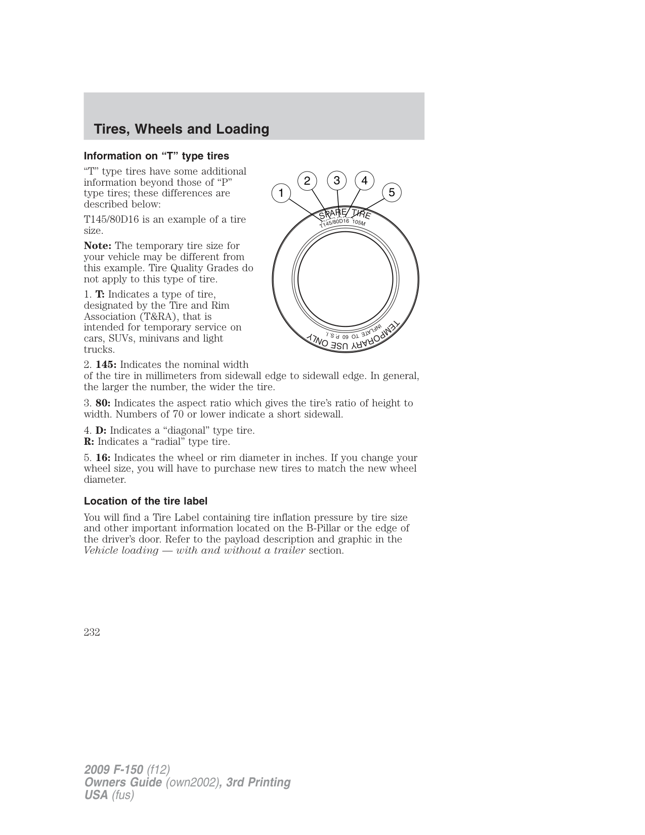
Vehicle loading — with and without a trailer section.
###### TIRE PRESSURE MONITORING SYSTEM (TPMS) (IF EQUIPPED)
Each tire, including the spare (if provided), should be checked monthly when cold and inflated to the inflation pressure recommended by the vehicle manufacturer on the vehicle placard or tire inflation pressure label. (If your vehicle has tires of a different size than the size indicated on the vehicle placard or tire inflation pressure label, you should determine the proper tire inflation pressure for those tires.)
As an added safety feature, your vehicle has been equipped with a tire pressure monitoring system (TPMS) that illuminates a low tire pressure telltale when one or more of your tires is significantly under-inflated. Accordingly, when the low tire pressure telltale illuminates, you should stop and check your tires as soon as possible, and inflate them to the proper pressure. Driving on a significantly under-inflated tire causes the tire to overheat and can lead to tire failure. Under-inflation also reduces fuel efficiency and tire tread life, and may affect the vehicle’s handling and stopping ability.
Please note that the TPMS is not a substitute for proper tire maintenance, and it is the driver’s responsibility to maintain correct tire pressure, even if under-inflation has not reached the level to trigger illumination of the TPMS low tire pressure telltale.
Your vehicle has also been equipped with a TPMS malfunction indicator to indicate when the system is not operating properly. The TPMS malfunction indicator is combined with the low tire pressure telltale. When the system detects a malfunction, the telltale will flash for approximately one minute and then remain continuously illuminated. This sequence will continue upon subsequent vehicle start-ups as long as the malfunction exists.
When the malfunction indicator is illuminated, the system may not be able to detect or signal low tire pressure as intended. TPMS malfunctions may occur for a variety of reasons, including the installation of replacement or alternate tires or wheels on the vehicle that prevent the TPMS from functioning properly. Always check the TPMS malfunction telltale after replacing one or more tires or wheels on your vehicle to ensure that the replacement or alternate tires and wheels allow the TPMS to continue to function properly.
The Tire Pressure Monitoring System complies with part 15 of the FCC rules and with RSS-210 of Industry Canada. Operation is subject to the following two conditions: (1) This device may not cause harmful interference, and (2) This device must accept any interference received, including interference that may cause undesired operation.
WARNING: The Tire Pressure Monitoring System is NOT a substitute for manually checking tire pressure. The tire pressure
should be checked periodically (at least monthly) using a tire gauge, see Inflating your tires in this chapter. Failure to properly maintain your tire pressure could increase the risk of tire failure, loss of control, vehicle rollover and personal injury.
Changing tires with TPMS Each road tire is equipped with a tire pressure sensor located inside the tire/wheel cavity. The pressure sensor is attached to the valve stem. The pressure sensor is covered by the tire and is not visible unless the tire is removed. Care must be taken when changing the tire to avoid damaging the sensor. It is recommended that you always have your tires serviced by an authorized dealer.
The tire pressure should be checked periodically (at least monthly) using an accurate tire gauge, refer to Inflating your tires in this chapter.
###### Understanding your Tire Pressure Monitoring System (TPMS)
The Tire Pressure Monitoring System measures pressure in your four road tires and sends the tire pressure readings to your vehicle. The Low Tire Warning Lamp will turn ON if the tire pressure is significantly low. Once the light is illuminated, your tires are under inflated and need to be inflated to the manufacturer’s recommended tire pressure. Even if the light turns ON and a short time later turns OFF, your tire pressure still needs to be checked. Visit www.checkmytires.org for additional information.
###### When your temporary spare tire is installed
When one of your road tires needs to be replaced with the temporary spare, the TPMS system will continue to identify an issue to remind you that the damaged road wheel/tire needs to be repaired and put back on your vehicle.
To restore the full functionality of the Tire Pressure Monitoring System, have the damaged road wheel/tire repaired and remounted on your vehicle. For additional information, refer to Changing tires with TPMS in this section.
###### When you believe your system is not operating properly
The main function of the Tire Pressure Monitoring System is to warn you when your tires need air. It can also warn you in the event the system is no longer capable of functioning as intended. Please refer to the following chart for information concerning your Tire Pressure Monitoring System:
|Low Tire Pressure Warning Light|Possible cause|Customer Action Required|
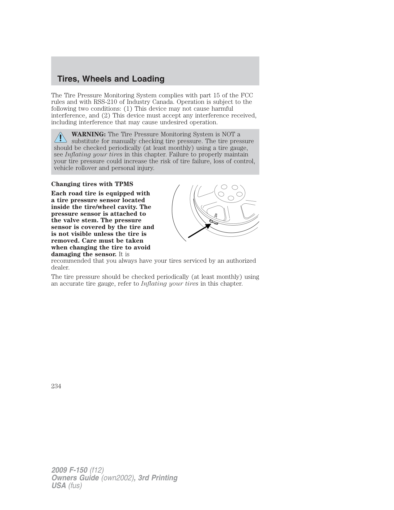
|---|---|---| |Solid Warning Light|Tire(s) under-inflated|1. Check your tire pressure to ensure tires are properly inflated; refer to Inflating your tires in this chapter.
2. After inflating your tires to the manufacturer’s recommended inflation pressure as shown on the Tire Label (located on the edge of driver’s door or the B-Pillar), the vehicle must be driven for at least two minutes over 20 mph (32 km/h) before the light will turn OFF.
| |Solid Warning Light|Spare tire in use|Your temporary spare tire is in use. Repair the damaged road wheel/tire and reinstall it on the vehicle to restore system functionality. For a description on how the system functions, refer to When your temporary spare tire is installed in this section.| |Solid Warning Light|TPMS malfunction|If your tires are properly inflated and your spare tire is not in use and the light remains ON, have the system inspected by your authorized dealer.| |Solid Warning Light|Tire rotation without sensor training|On vehicles with different front and rear tire pressures, the TPMS system must be retrained following every tire rotation. Refer to Tire rotation in this chapter.|
|Low Tire Pressure Warning Light|Possible cause|Customer Action Required| |---|---|---| |Flashing Warning Light|Spare tire in use|Your temporary spare tire is in use. Repair the damaged road wheel and re-mount it on the vehicle to restore system functionality. For a description of how the system functions under these conditions, refer to When your temporary spare tire is installed in this section.| |Flashing Warning Light|TPMS malfunction|If your tires are properly inflated and your spare tire is not in use and the TPMS warning light still flashes, have the system inspected by your authorized dealer.|
###### When inflating your tires
When putting air into your tires (such as at a gas station or in your garage), the Tire Pressure Monitoring System may not respond immediately to the air added to your tires.
It may take up to two minutes of driving over 20 mph (32 km/h) for the light to turn OFF after you have filled your tires to the recommended inflation pressure.
###### How temperature affects your tire pressure
The Tire Pressure Monitoring System (TPMS) monitors tire pressure in each pneumatic tire. While driving in a normal manner, a typical passenger tire inflation pressure may increase approximately 2 to 4 psi (14 to 28 kPa) from a cold start situation. If the vehicle is stationary over night with the outside temperature significantly lower than the daytime temperature, the tire pressure may decrease approximately 3 psi (20.7 kPa) for a drop of 30° F (16.6°C) in ambient temperature. This lower pressure value may be detected by the TPMS as being significantly lower than the recommended inflation pressure and activate the TPMS warning for low tire pressure. If the low tire pressure warning light is ON, visually check each tire to verify that no tire is flat. (If one or more tires are flat, repair as necessary.) Check air pressure in the road tires. If any tire is under-inflated, carefully drive the vehicle to the nearest location where air can be added to the tires. Inflate all the tires to the recommended inflation pressure.
TPMS reset procedure (if applicable)
The TPMS reset tool is ONLY provided for vehicles with different front and rear tire pressures. The TPMS reset procedure needs to be performed after tire rotation only on these vehicles.
WARNING: To determine if your vehicle has different recommended pressures for the front and rear tires, refer to the
Safety Compliance Certification Label or Tire Label which is located on the B-Pillar or the edge of the driver’s door. See Vehicle Loading in this chapter for more information.
###### Overview
To provide the vehicle’s load carrying capability, some trucks require different recommended tire pressures in the front tires as compared to the rear tires. The Tire Pressure Monitoring System (TPMS) equipped on these vehicles is designed to illuminate the Low Tire Pressure Warning indicator at two different pressures; one for the front tires and one for the rear tires.
Since tires need to be rotated to provide consistent performance and maximum tire life, the Tire Pressure Monitoring System needs to know when the tires are rotated to determine which set of tires are on the front and which are on the rear. With this information, the system can detect and properly warn of low tire pressures.
WARNING: Always perform the TPMS reset procedure after tire rotation when recommended pressures are different for the front
and rear tires.
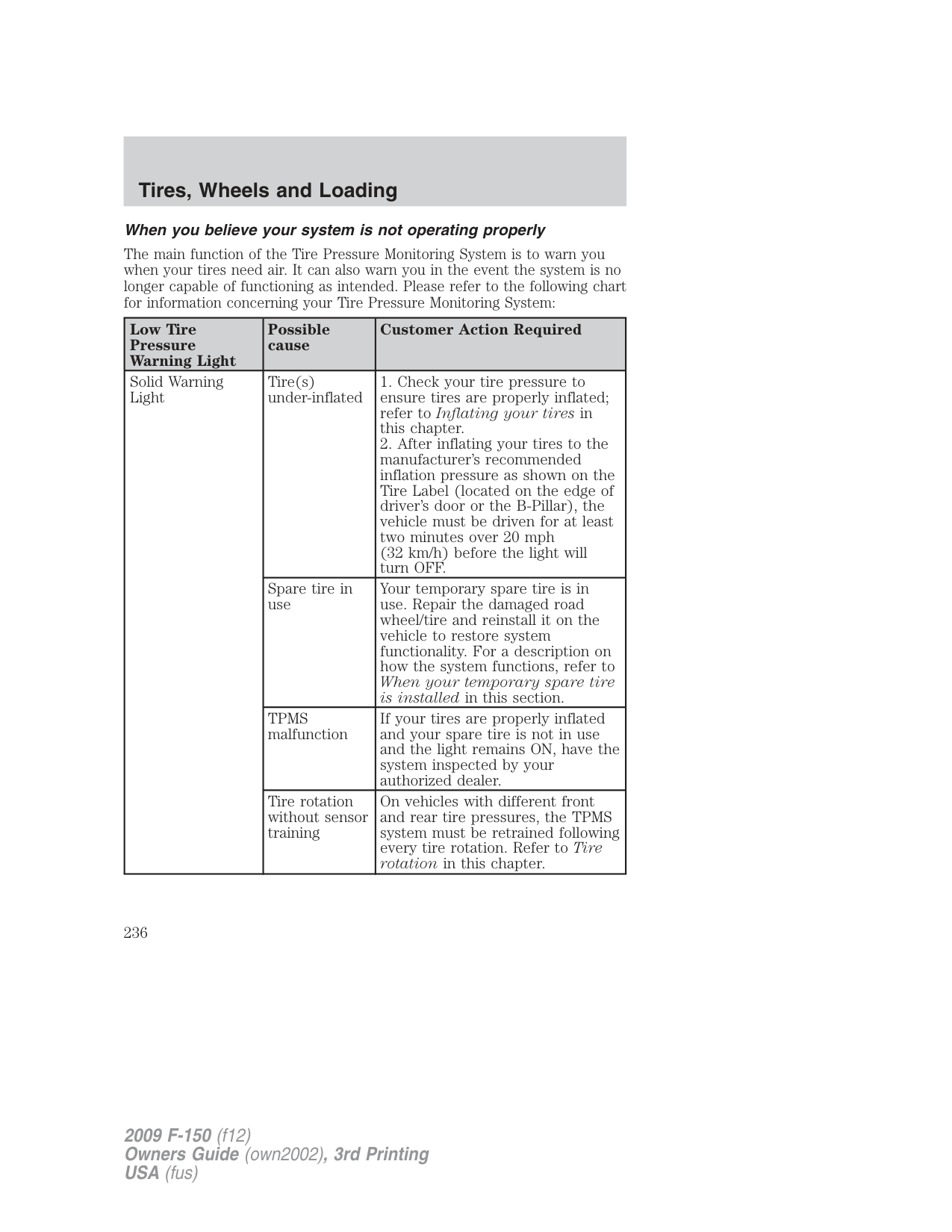
###### TPMS reset tool
A special TPMS reset tool to reset your TPMS after tire rotation is provided with vehicles that have different front and rear tire pressures. The tool is located with your Owner’s Guide materials.
Please take the tool with the provided Velcro strip on the back and mount it in the bottom right corner of your Owner’s Guide case (as shown) for safe keeping.
If you find that the reset tool was not provided when delivered, has been lost or no longer functions (the battery is not replaceable), please contact your authorized dealer to obtain a replacement.
To verify that your TPMS reset tool is working, press and release the button on the center of the TPMS tool. The red light should illuminate and remain on for approximately five (5) seconds. If the light does not illuminate, the tool needs to be replaced.
###### TPMS reset tips:
TPMS reset procedure It is recommended that you read the entire procedure before attempting. Note: To enter the reset mode, Steps 1–6 MUST be completed within 60 seconds.
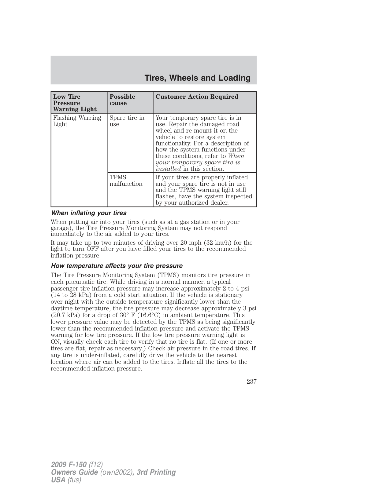
If the reset mode has been entered successfully, the horn will sound once, the TPMS indicator will flash and the message center will display TRAIN LEFT FRONT TIRE.
If after repeated attempts to enter the reset mode, the horn does not sound, the TPMS indicator does not flash and the message center does not display TRAIN LEFT FRONT TIRE, seek service from your authorized dealer.
Turn the ignition to off. If two short horn beeps are heard, the reset procedure was unsuccessful and must be repeated.
If after repeating the procedure and two short beeps are heard when the ignition is turned to off, seek assistance from your authorized dealer.
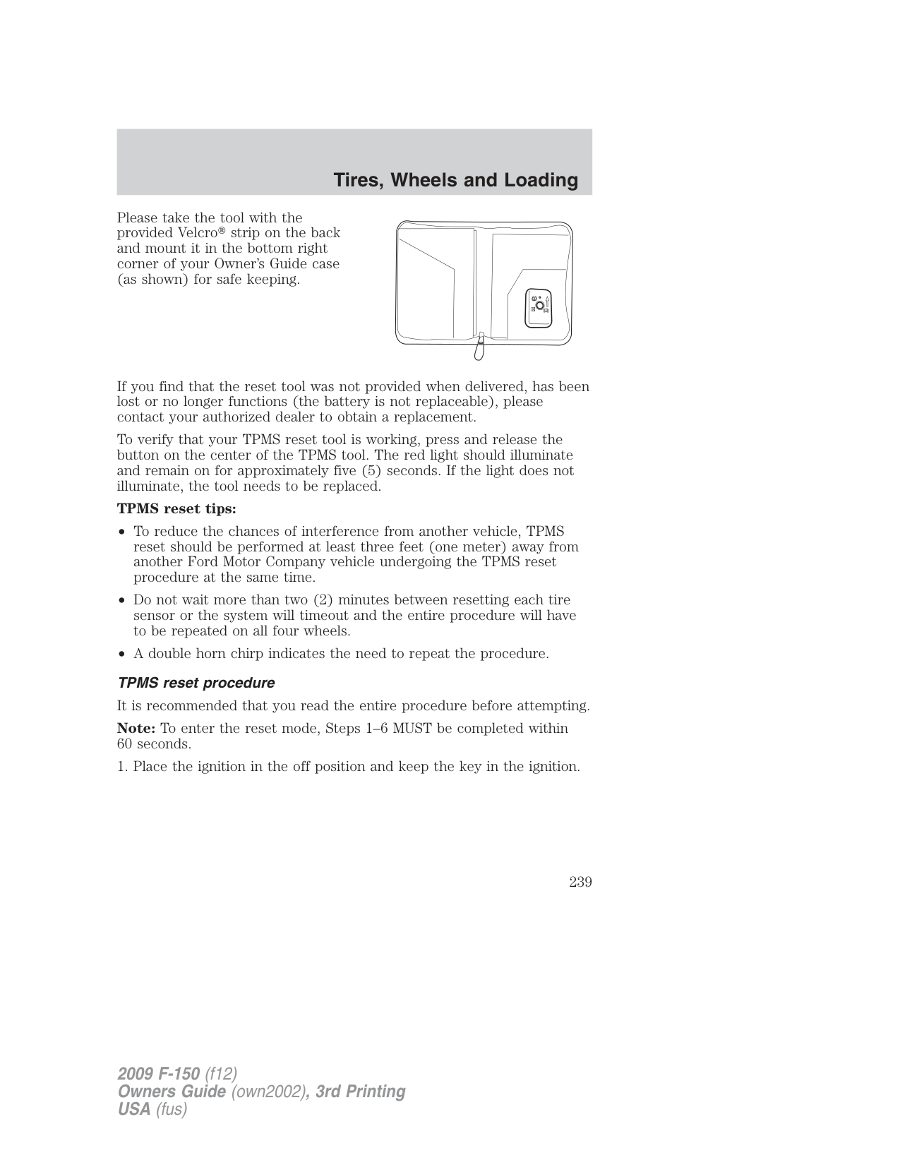
###### SNOW TIRES AND CHAINS
WARNING: Snow tires must be the same size, load index, speed rating as those originally provided by Ford. Use of any tire or
wheel not recommended by Ford can affect the safety and performance of your vehicle, which could result in an increased risk of loss of vehicle control, vehicle rollover, personal injury and death. Additionally, the use of non-recommended tires and wheels could cause steering, suspension, axle or transfer case/power transfer unit failure.
The tires on your vehicle have all-weather treads to provide traction in rain and snow. However, in some climates, you may need to use snow tires and chains. If you need to use chains, it is recommended that steel wheels (of the same size and specifications) be used, as chains may chip aluminum wheels.
Note: Do not place chains on the following tires sizes: P265/60R18, P275/65R18, LT275/70R17, LT275/65R18, P275/55R20, and P275/45R22. Follow these guidelines when using snow tires and chains:
###### VEHICLE LOADING – WITH AND WITHOUT A TRAILER
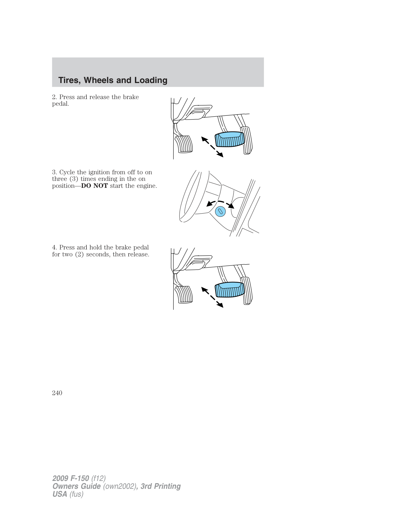
This section will guide you in the proper loading of your vehicle and/or trailer, to keep your loaded vehicle weight within its design rating capability, with or without a trailer. Properly loading your vehicle will provide maximum return of vehicle design performance. Before loading your vehicle, familiarize yourself with the following terms for determining your vehicle’s weight ratings, with or without a trailer, from the vehicle’s Tire Label or Safety Compliance Certification Label:
Base Curb Weight – is the weight of the vehicle including a full tank of fuel and all standard equipment. It does not include passengers, cargo, or optional equipment.
Vehicle Curb Weight – is the weight of your new vehicle when you picked it up from your authorized dealer plus any aftermarket equipment.
Payload – is the combined weight of cargo and passengers that the vehicle is carrying. The maximum payload for your vehicle can be found on the Tire Label on the B-Pillar or the edge of the driver’s door (vehicles exported outside the US and Canada may not have a Tire Label). Look for “THE COMBINED WEIGHT OF OCCUPANTS AND CARGO SHOULD NEVER EXCEED XXX kg OR XXX lb.” for maximum payload. The payload listed on the Tire Label is the maximum payload for the vehicle as built by the assembly plant. If any aftermarket or authorized-dealer installed equipment has been installed on the vehicle, the weight of the equipment must be subtracted from the payload listed on the Tire Label in order to determine the new payload.
WARNING: The appropriate loading capacity of your vehicle can be limited either by volume capacity (how much space is
available) or by payload capacity (how much weight the vehicle should carry). Once you have reached the maximum payload of your vehicle, do not add more cargo, even if there is space available. Overloading or improperly loading your vehicle can contribute to loss of vehicle control and vehicle rollover.
###### Example only:

| | | | | |---|---|---|---| | | | | | | | | | |
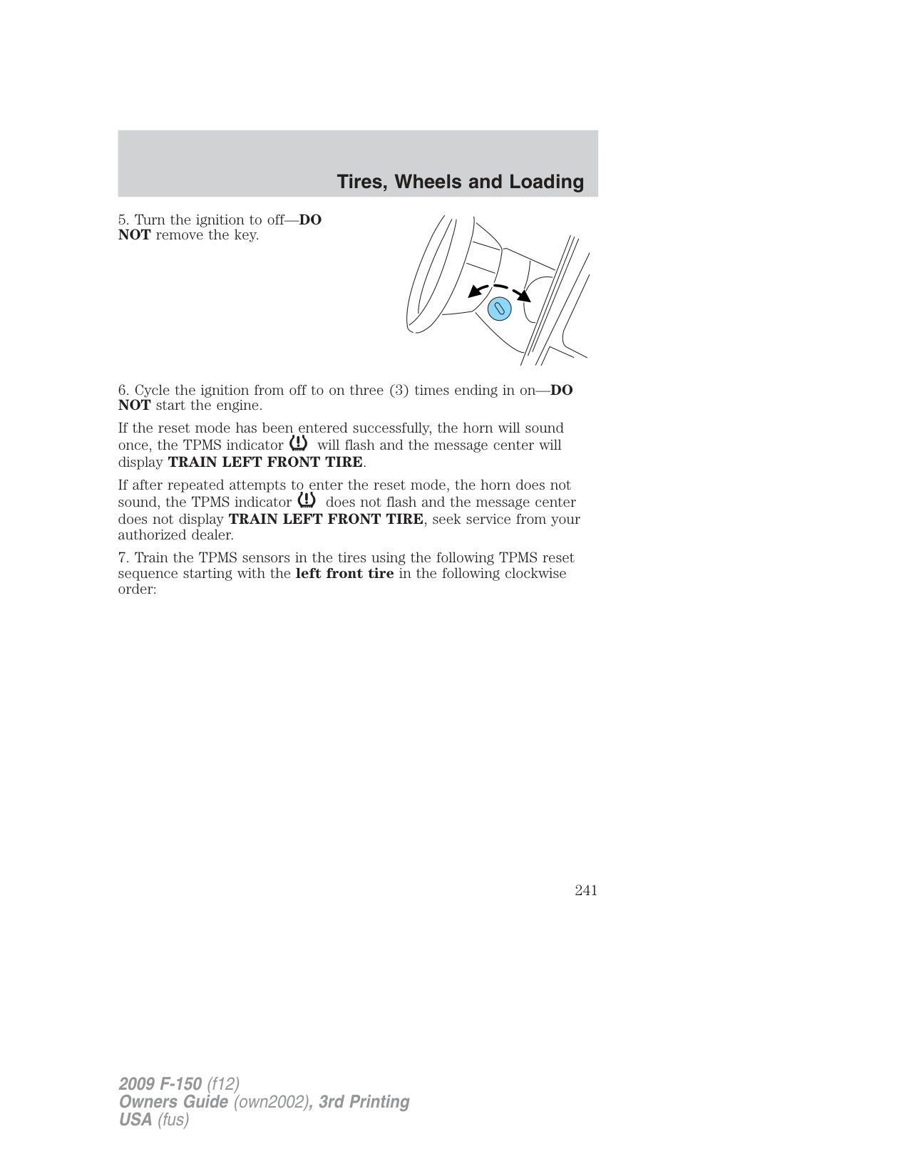
| | | | |

Cargo Weight – includes all weight added to the Base Curb Weight, including cargo and optional equipment. When towing, trailer tongue load or king pin weight is also part of cargo weight.
GAW (Gross Axle Weight) – is the total weight placed on each axle (front and rear) – including vehicle curb weight and all payload.
GAWR (Gross Axle Weight Rating) – is the maximum allowable weight that can be carried by a single axle (front or rear). These numbers are shown on the Safety Compliance Certification Label located on the B-Pillar or the edge of the driver’s door. The total load on each axle must never exceed its GAWR.
Note: For trailer towing information refer to Trailer towing found in this chapter or the RV and Trailer Towing Guide provided by your authorized dealer.
GVW (Gross Vehicle Weight) – is the Vehicle Curb Weight + cargo + passengers.
GVWR (Gross Vehicle Weight Rating) – is the maximum allowable weight of the fully loaded vehicle (including all options, equipment, passengers and cargo). The GVWR is shown on the Safety Compliance Certification Label located on the B-Pillar or the edge of the driver’s door. The GVW must never exceed the GVWR.
WARNING: Exceeding the Safety Compliance Certification Label vehicle weight rating limits could result in substandard vehicle
handling or performance, engine, transmission and/or structural damage, serious damage to the vehicle, loss of control and personal injury.
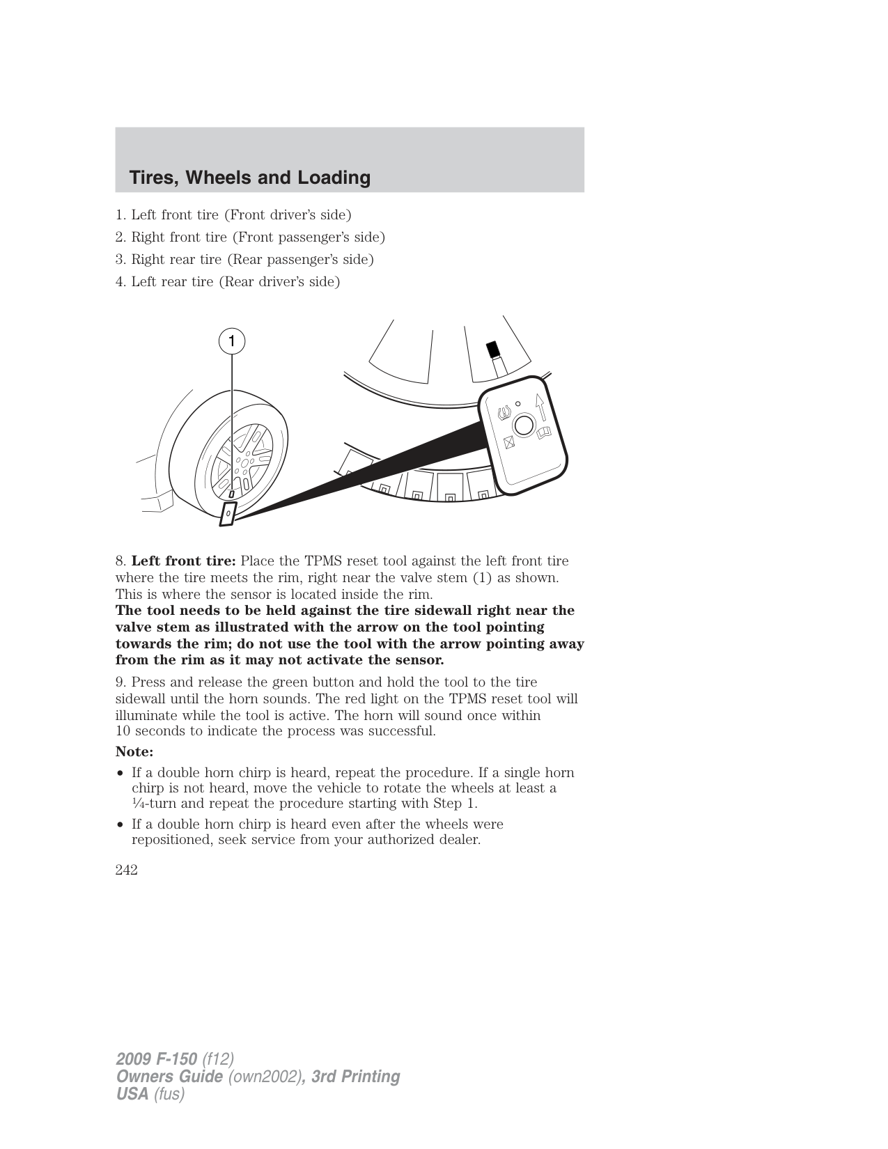
GCW (Gross Combined Weight) – is the weight of the loaded vehicle (GVW) plus the weight of the fully loaded trailer.
GCWR (Gross Combined Weight Rating) – is the maximum allowable weight of the vehicle and the loaded trailer – including all cargo and passengers – that the vehicle can handle without risking damage. (Important: The towing vehicle’s braking system is rated for operation at GVWR, not at GCWR.) Separate functional brakes should be used for safe control of towed vehicles and for trailers where the GCW of the towing vehicle plus the trailer exceed the GVWR of the towing vehicle. The GCW must never exceed the GCWR. Maximum Loaded Trailer Weight – is the highest possible weight of a fully loaded trailer the vehicle can tow. It assumes a vehicle with only mandatory options, no cargo (internal or external), a tongue load of 10–15% (conventional trailer) or king pin weight of 15–25% (fifth wheel trailer), and driver only (150 lb. [68 kg]). Consult your authorized dealer (or the RV and Trailer Towing Guide provided by your authorized dealer) for more detailed information. Tongue Load or Fifth Wheel King Pin Weight – refers to the amount of the weight that a trailer pushes down on a trailer hitch. Examples: For a 5,000 lb. (2,268 kg) conventional trailer, multiply 5,000 by 0.10 and 0.15 to obtain a proper tongue load range of 500 to 750 lb. (227 to 340 kg). For an 11,500 lb. (5,216 kg) fifth wheel trailer, multiply by 0.15 and 0.25 to obtain a proper king pin load range of 1,725 to 2,875 lb. (782 to 1,304 kg)
WARNING: Do not exceed the GVWR or the GAWR specified on the Safety Compliance Certification Label.
WARNING: Do not use replacement tires with lower load carrying capacities than the original tires because they may
lower the vehicle’s GVWR and GAWR limitations. Replacement tires with a higher limit than the original tires do not increase the GVWR and GAWR limitations.
WARNING: Exceeding any vehicle weight rating limitation could result in serious damage to the vehicle and/or personal injury.
###### Steps for determining the correct load limit:
= 650 lb.). In metric units (635-340 (5 x 68) = 295 kg.)
The following gives you a few examples on how to calculate the available amount of cargo and luggage load capacity:
1400 - (2 x 220) - (9 x 100) = 1400 - 440 - 900 = 60 lb. Now you have the load capacity to transport the cement and your friend home. In metric units, the calculation would be: 635 kg - (2 x 99 kg) - (9 x 45 kg) = 635 - 198 - 405 = 32 kg.
The above calculations also assume that the loads are positioned in your vehicle in a manner that does not overload the Front or the Rear Gross Axle Weight Rating specified for your vehicle on the Safety Compliance Certification Label found on the edge of the driver’s door.
Special loading instructions for owners of pickup trucks and utility-type vehicles
WARNING: For important information regarding safe operation of this type of vehicle, see the Preparing to drive your vehicle
section in the Driving chapter of this Owner’s Guide.
WARNING: Loaded vehicles may handle differently than unloaded vehicles. Extra precautions, such as slower speeds and
increased stopping distance, should be taken when driving a heavily loaded vehicle.
Your vehicle can haul more cargo and people than most passenger cars. Depending upon the type and placement of the load, hauling cargo and people may raise the center of gravity of the vehicle.
TRAILER TOWING Your vehicle may tow a class I, II, III or IV trailer provided the maximum trailer weight is less than or equal to the maximum trailer weight listed for your engine and rear axle ratio on the following charts.
If your vehicle is not equipped with a heavy-duty trailer towing package, the maximum weight your vehicle can tow is limited to 5,000 lb. (2,268 kg)
Your vehicle’s load capacity is designated by weight, not by volume, so you cannot necessarily use all available space when loading a vehicle.
Towing a trailer places an additional load on your vehicle’s engine, transmission, axle, brakes, tires and suspension. Inspect these components carefully periodically during, and after any towing operation.
Exceeding the maximum GCWR could result in extensive damage to your vehicle and personal injury.
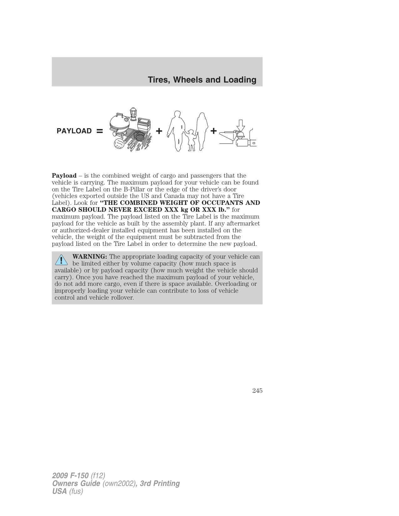
WARNING: Do not exceed the GVWR or the GAWR specified on the certification label.
WARNING: Towing trailers beyond the maximum recommended gross trailer weight exceeds the limit of the vehicle and could
result in engine damage, transmission damage, structural damage, loss of vehicle control, vehicle rollover and personal injury.
|Regular Cab 4x2 (126” wheelbase)|Regular Cab 4x2 (126” wheelbase)|Regular Cab 4x2 (126” wheelbase)|Regular Cab 4x2 (126” wheelbase)| |---|---|---|---| |Engine|Rear axle ratio|Maximum GCWR-lb. (kg)|Maximum trailer weight-lb. (kg)| |4.6L 2V|3.55|10400 (4717)|5400 (2449)| |4.6L 2V|3.73|10900 (4944)|5900 (2676)|
|Regular Cab 4x4 (126” wheelbase)|Regular Cab 4x4 (126” wheelbase)|Regular Cab 4x4 (126” wheelbase)|Regular Cab 4x4 (126” wheelbase)| |---|---|---|---| |Engine|Rear axle ratio|Maximum GCWR-lb. (kg)|Maximum trailer weight-lb. (kg)| |4.6L 2V|3.73|10900 (4944)|5700 (2585)| |4.6L 3V|3.55|12900 (5851)|7700 (3493)| |4.6L 3V|3.73|13300 (6033)|8000 (3629)| |5.4L|3.31|13000 (5897)|7700 (3493)|
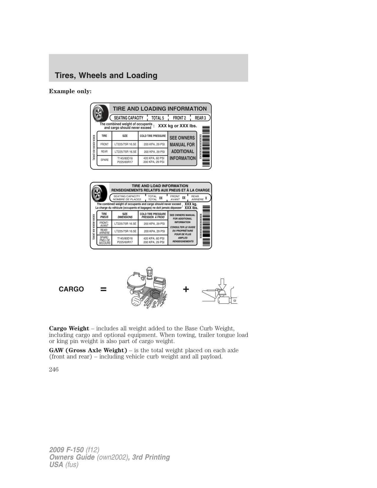
|5.4L|3.55|13900 (6305)|8600 (3901)| |5.4L|3.73|13900 (6305)|8600 (3901)|
|Regular Cab 4x2 (145” wheelbase)|Regular Cab 4x2 (145” wheelbase)|Regular Cab 4x2 (145” wheelbase)|Regular Cab 4x2 (145” wheelbase)| |---|---|---|---| |Engine|Rear axle ratio|Maximum GCWR-lb. (kg)|Maximum trailer weight-lb. (kg)| |4.6L 2V|3.55|10600 (4808)|5500 (2495)| |4.6L 2V|3.73|11100 (5035)|6000 (2722)| |4.6L 3V|3.31|13100 (5942)|8000 (3629)| |4.6L 3V|3.55|13600 (6169)|8400 (3810)| |5.4L|3.15|13200 (5987)|8000 (3629)| |5.4L|3.55|15000 (6804)|9800 (4445)| |5.4L (Heavy Duty)|3.73|16700 (7575)|11300 (5126)|
|Regular Cab 4x4 (145” wheelbase)|Regular Cab 4x4 (145” wheelbase)|Regular Cab 4x4 (145” wheelbase)|Regular Cab 4x4 (145” wheelbase)| |---|---|---|---| |Engine|Rear axle ratio|Maximum GCWR-lb. (kg)|Maximum trailer weight-lb. (kg)| |4.6L 2V|3.73|11100 (5035)|5500 (2495)|
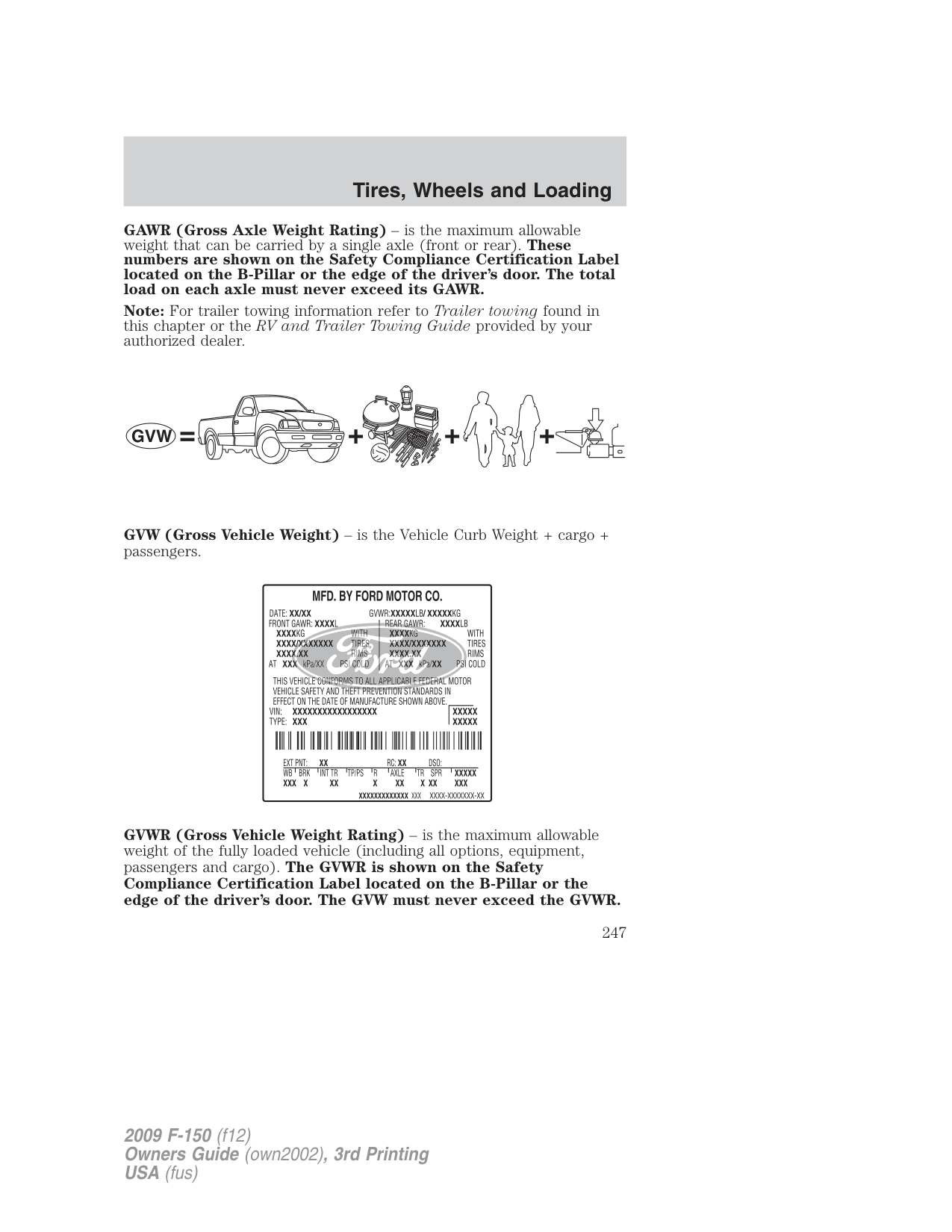
|4.6L 3V|3.55|13100 (5942)|7800 (3538)| |4.6L 3V|3.73|12600 (5715)|8200 (3719)| |5.4L|3.31|13200 (5987)|7800 (3538)| |5.4L|3.55|15000 (6804)|9500 (4309)| |5.4L|3.73|15000 (6804)|9500 (4309)| |5.4L (Heavy Duty)|3.73|17000 (7711)|11300 (5126)|
|SuperCab 4x2 (133” wheelbase)|SuperCab 4x2 (133” wheelbase)|SuperCab 4x2 (133” wheelbase)|SuperCab 4x2 (133” wheelbase)| |---|---|---|---| |Engine|Rear axle ratio|Maximum GCWR-lb. (kg)|Maximum trailer weight-lb. (kg)| |4.6L 2V|3.55|10400 (4717)|5200 (2359)| |4.6L 2V|3.73|10900 (4944)|5700 (2585)| |4.6L 3V|3.31|13000 (5897)|7800 (3538)| |4.6L 3V|3.55|13500 (6123)|8200 (3719)|
|SuperCab 4x2 (133” wheelbase)|SuperCab 4x2 (133” wheelbase)|SuperCab 4x2 (133” wheelbase)|SuperCab 4x2 (133” wheelbase)| |---|---|---|---| |Engine|Rear axle ratio|Maximum GCWR-lb. (kg)|Maximum trailer weight-lb. (kg)|
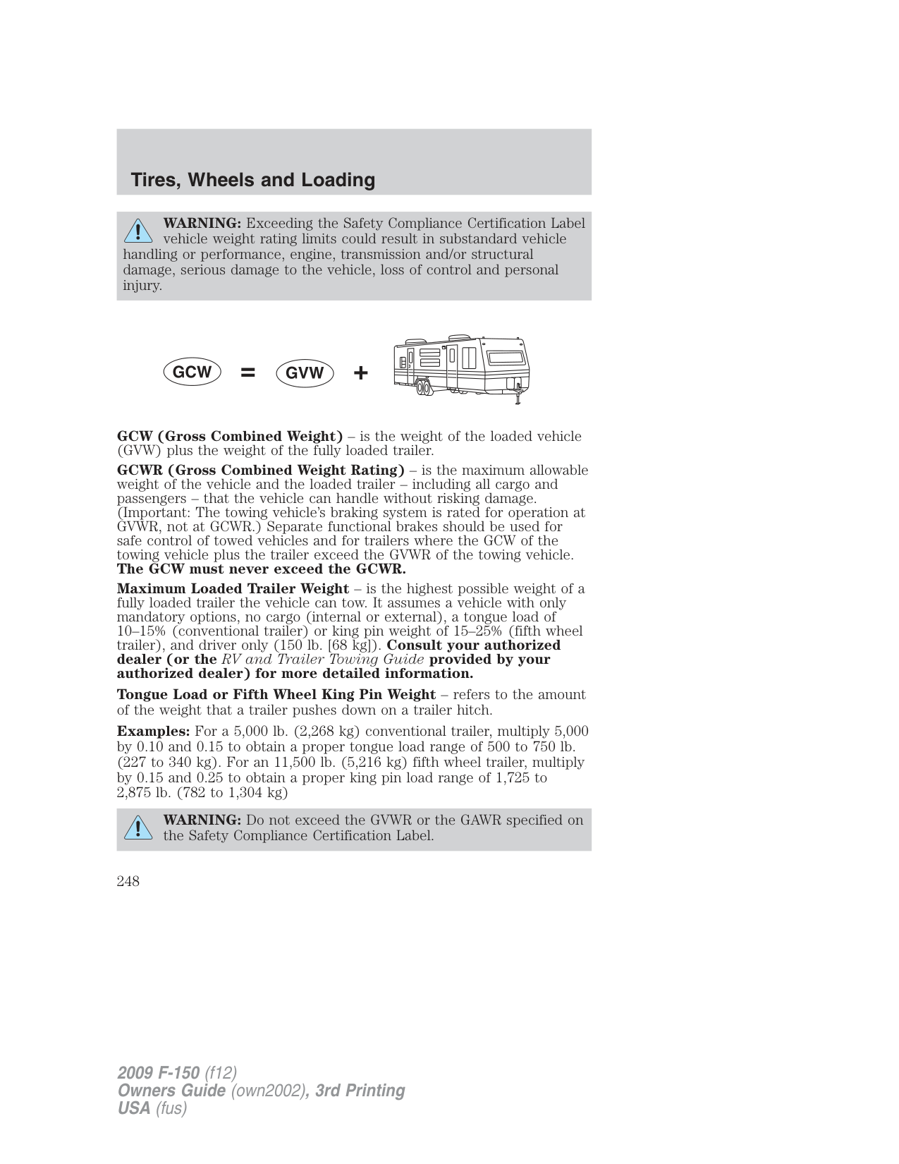
|5.4L|3.15|13200 (5987)|7800 (3538)| |5.4L|3.55|14000 (6350)|8600 (3901)|
|SuperCab 4x4 (133” wheelbase)|SuperCab 4x4 (133” wheelbase)|SuperCab 4x4 (133” wheelbase)|SuperCab 4x4 (133” wheelbase)| |---|---|---|---| |Engine|Rear axle ratio|Maximum GCWR-lb. (kg)|Maximum trailer weight-lb. (kg)| |4.6L 2V|3.73|10900 (4944)|5400 (2449)| |4.6L 3V|3.55|13000 (5897)|7500 (3402)| |4.6L 3V|3.73|13500 (6123)|8000 (3629)| |5.4L|3.31|13200 (5987)|7600 (3447)| |5.4L|3.55|14000 (6350)|8400 (3810)| |5.4L|3.73|14000 (6350)|8400 (3810)|
|SuperCab 4x2 (145” wheelbase)|SuperCab 4x2 (145” wheelbase)|SuperCab 4x2 (145” wheelbase)|SuperCab 4x2 (145” wheelbase)| |---|---|---|---| |Engine|Rear axle ratio|Maximum GCWR-lb. (kg)|Maximum trailer weight-lb. (kg)| |4.6L 2V|3.55|10600 (4808)|5300 (24004)| |4.6L 2V|3.73|11100 (5035)|5800 (2631)|
|4.6L 3V|3.31|13500 (6123)|8200 (3719)| |4.6L 3V|3.55|14900 (6759)|9500 (4309)| |5.4L|3.15|14000 (6350)|8600 (3900)| |5.4L|3.55|15200 (6895)|9800 (4445)| |5.4L|3.73|16900 (7666)|11300 (5126)|
|SuperCab 4x4 (145” wheelbase)|SuperCab 4x4 (145” wheelbase)|SuperCab 4x4 (145” wheelbase)|SuperCab 4x4 (145” wheelbase)| |---|---|---|---| |Engine|Rear axle ratio|Maximum GCWR-lb. (kg)|Maximum trailer weight-lb. (kg)| |4.6L 2V|3.73|11100 (5035)|5500 (2495)| |4.6L 3V|3.55|13500 (6123)|7900 (3583)| |4.6L 3V|3.73|15100 (6849)|9400 (4264)| |5.4L|3.31|14000 (6350)|8300 (3765)| |5.4L|3.55|15400 (6985)|9700 (4400)| |5.4L|3.73|15400 (6985) 17100 (7756)*|9700 (4400) 11200 (5080)*|
####### *Maximum GCWR and trailer weight when equipped with Max TrailerTow package.
|SuperCab 4x2 (163” wheelbase)|SuperCab 4x2 (163” wheelbase)|SuperCab 4x2 (163” wheelbase)|SuperCab 4x2 (163” wheelbase)| |---|---|---|---| |Engine|Rear axle ratio|Maximum GCWR-kg (lb.)|Maximum trailer weight-kg (lb.)| |5.4L (Heavy Duty)|3.73|17100 (7756)|11300 (5126)|
|SuperCab 4x4 (163” wheelbase)|SuperCab 4x4 (163” wheelbase)|SuperCab 4x4 (163” wheelbase)|SuperCab 4x4 (163” wheelbase)| |---|---|---|---| |Engine|Rear axle ratio|Maximum GCWR-lb. (kg)|Maximum trailer weight-lb. (kg)| |5.4L (Heavy Duty)|3.73|17100 (7756)|11100 (5035)|
|SuperCrew 4x2 (145” wheelbase)|SuperCrew 4x2 (145” wheelbase)|SuperCrew 4x2 (145” wheelbase)|SuperCrew 4x2 (145” wheelbase)| |---|---|---|---| |Engine|Rear axle ratio|Maximum GCWR-lb. (kg)|Maximum trailer weight-lb. (kg)| |4.6L 2V|3.55|10600 (4808)|5200 (2359)| |4.6L 2V|3.73|11100 (5035)|5700 (2585)|
|SuperCrew 4x2 (145” wheelbase)|SuperCrew 4x2 (145” wheelbase)|SuperCrew 4x2 (145” wheelbase)|SuperCrew 4x2 (145” wheelbase)|
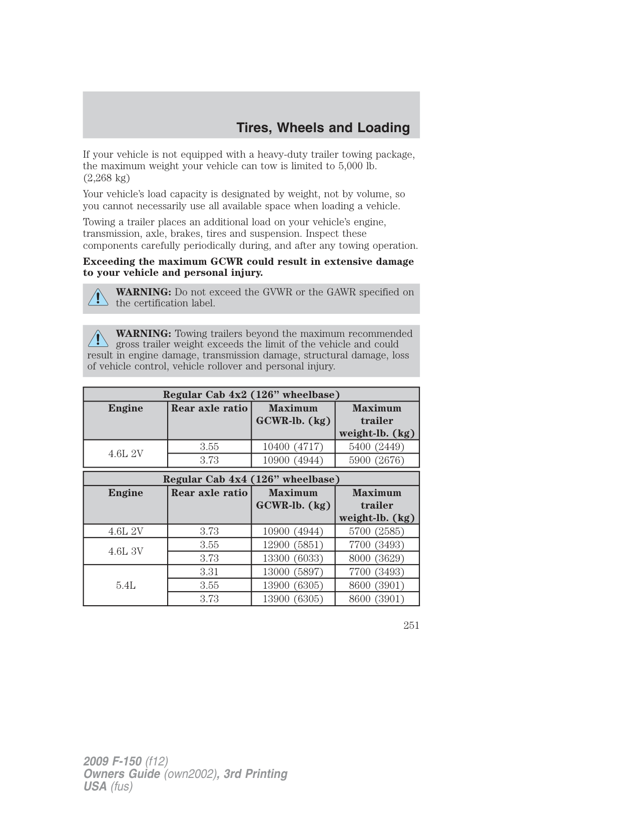
|---|---|---|---| |Engine|Rear axle ratio|Maximum GCWR-lb. (kg)|Maximum trailer weight-lb. (kg)| |4.6L 3V|3.31|13500 (6123)|8100 (3674)| |4.6L 3V|3.55|14900 (6759)|9500 (4309)| |4.6L 3V|3.15|13000 (5897)|7500 (3402)| |5.4L|3.15|14000 (6350)|8500 (3856)| |5.4L|3.55|15300 (6940)|9800 (4445)| |5.4L|3.73|16900 (7666)|11300 (5126)|
|SuperCrew 4x4 (145” wheelbase)|SuperCrew 4x4 (145” wheelbase)|SuperCrew 4x4 (145” wheelbase)|SuperCrew 4x4 (145” wheelbase)| |---|---|---|---| |Engine|Rear axle ratio|Maximum GCWR-lb. (kg)|Maximum trailer weight-lb. (kg)| |4.6L 3V|3.55|13500 (6123)|7700 (3493)| |4.6L 3V|3.73|15100 (6849)|9300 (4218)| |5.4L|3.31|14000 (6350)|8200 (3719)| |5.4L|3.55|15500 (7031)|9700 (4400)| |5.4L|3.73|15500 (7031) 17100 (7756)*|9700 (4400) 11200 (5080)*|
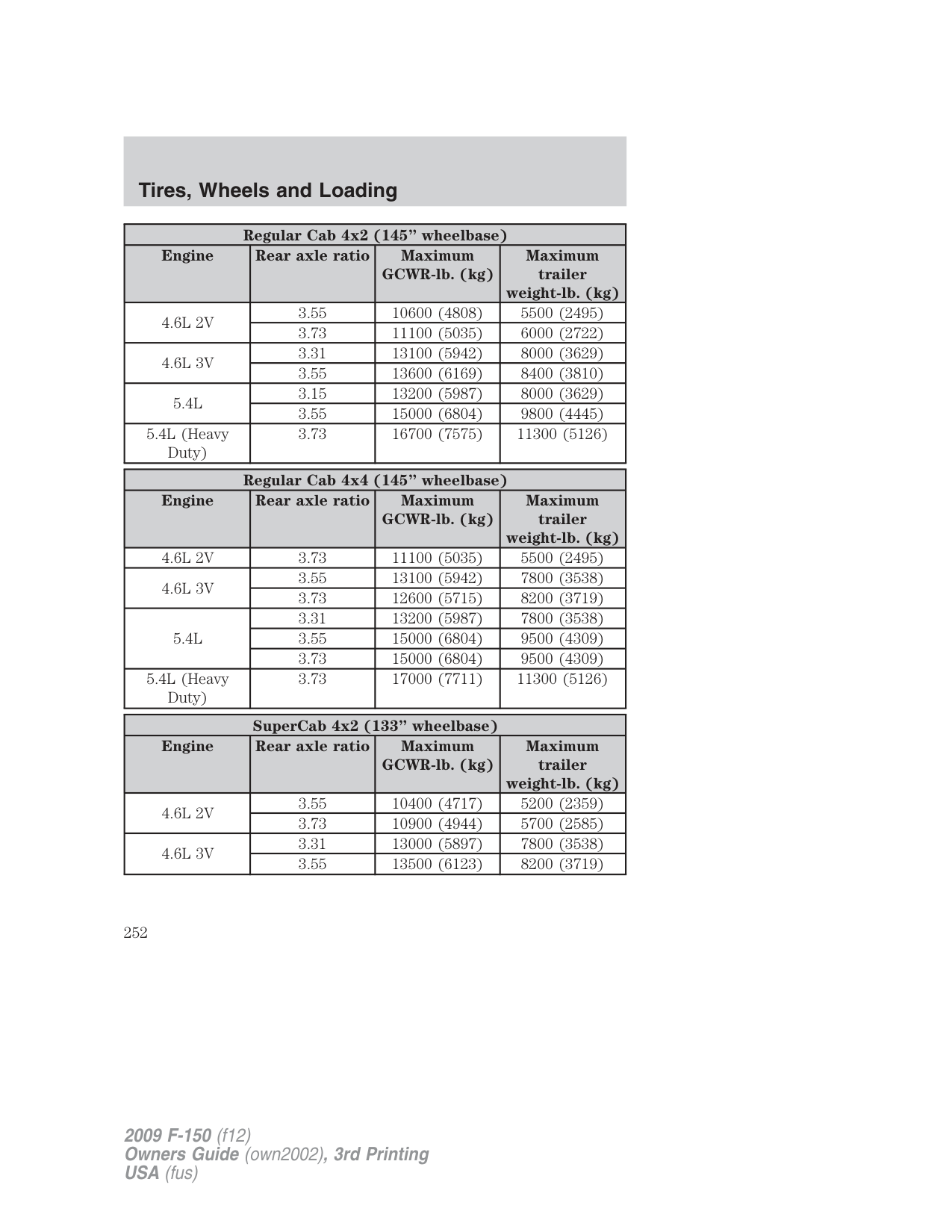
####### *Maximum GCWR and trailer weight when equipped with Max TrailerTow package.
|SuperCrew 4x2 (157” wheelbase)|SuperCrew 4x2 (157” wheelbase)|SuperCrew 4x2 (157” wheelbase)|SuperCrew 4x2 (157” wheelbase)| |---|---|---|---| |Engine|Rear axle ratio|Maximum GCWR-lb. (kg)|Maximum trailer weight-lb. (kg)| |4.6L 2V|3.55|10600 (4808)|5100 (2313)| |4.6L 2V|3.73|11100 (5035)|5600 (2540)| |4.6L 3V|3.31|13500 (6123)|8000 (3629)| |4.6L 3V|3.55|14900 (6759)|9300 (4218)| |5.4L|3.15|14000 (6350)|8400 (3810)| |5.4L|3.55|15300 (6940)|9700 (4400)|
|SuperCrew 4x4 (157” wheelbase)|SuperCrew 4x4 (157” wheelbase)|SuperCrew 4x4 (157” wheelbase)|SuperCrew 4x4 (157” wheelbase)| |---|---|---|---| |Engine|Rear axle ratio|Maximum GCWR-lb. (kg)|Maximum trailer weight-lb. (kg)| |4.6L 3V|3.55|13500 (6123)|7600 (3448)| |4.6L 3V|3.73|15100 (6849)|9200 (4173)| |5.4L|3.31|14000 (6350)|8100 (3674)| |5.4L|3.55|15500 (7031)|9600 (4354)|
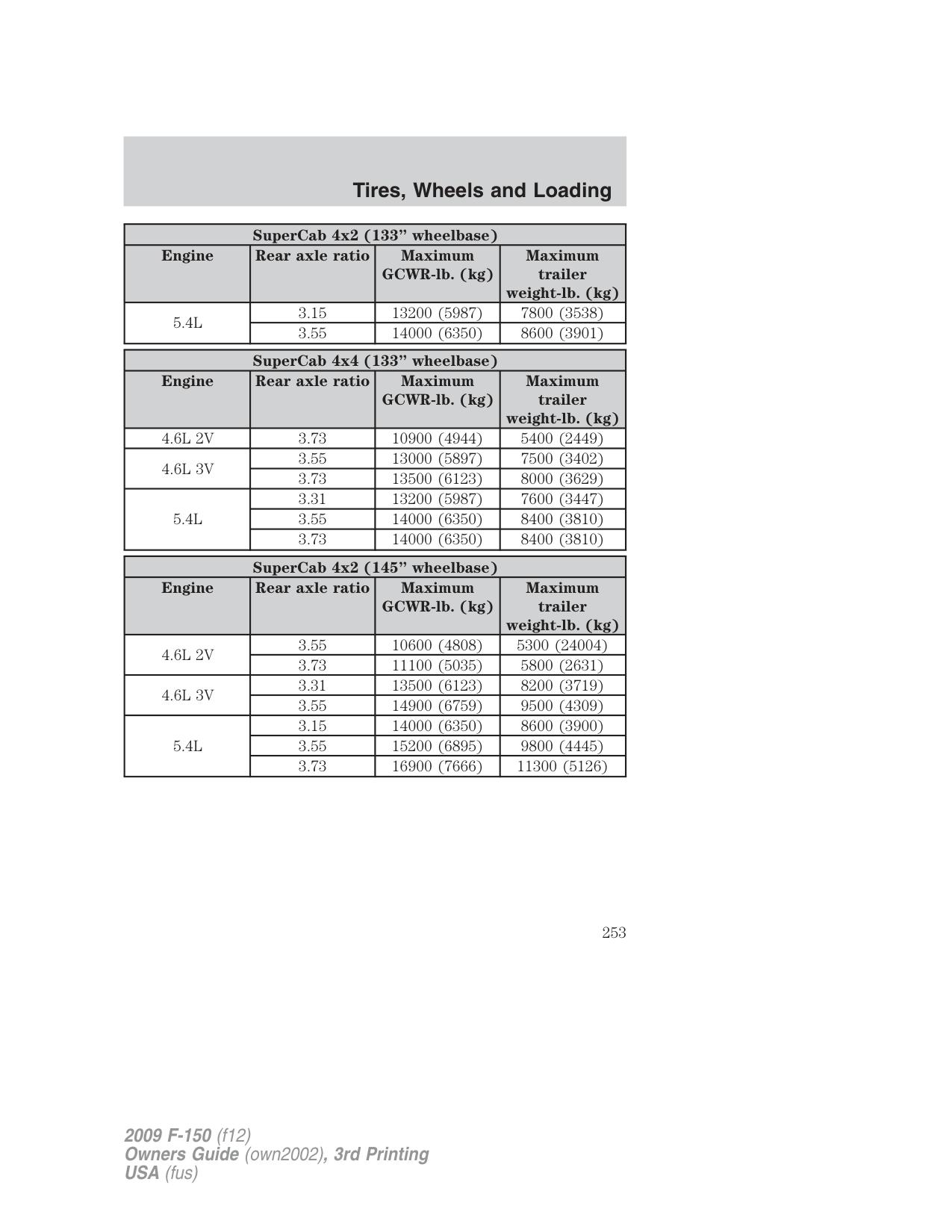
|5.4L|3.73|15500 (7031) 17100 (7756)*|9600 (4354) 11100 (5035)*|
• Not to exceed towing vehicle frontal area 36 square feet (3.4 square
meters) without the Class IV trailer towing package.
trailer towing package for vehicles with 3.15 rear axle ratio only. Note: Do not exceed trailer weight of 5,000 lb. (2,268 kg) when towing with bumper only. Preparing to tow Use the proper equipment for towing a trailer and make sure it is properly attached to your vehicle. Contact your authorized dealer or a reliable trailer dealer as soon as possible if you require assistance. Hitches
Do not use hitches that clamp onto the vehicle’s bumper or attach to the axle. You must distribute the load in your trailer so that 10%–15% of the total weight of the trailer is on the tongue.
###### Weight distributing hitch
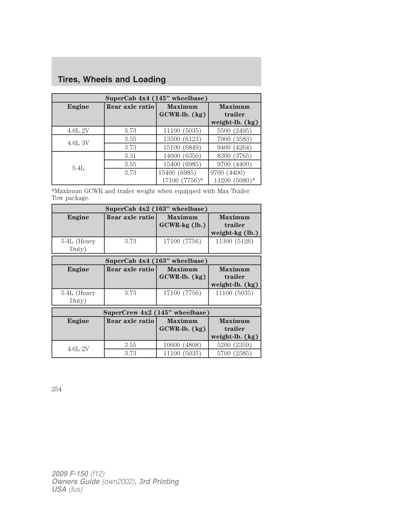
When hooking up a trailer using a load equalizing hitch, always use the following procedure:
at the center of the vehicle.
WARNING: Do not adjust a weight distributing hitch to any position where the rear bumper of the vehicle is higher than it
was before attaching the trailer. Doing so will defeat the function of the weight distributing hitch, which may cause unpredictable handling, and could result in serious personal injury.
###### Safety chains
Always connect the trailer’s safety chains to the frame or hook retainers of the vehicle hitch. To connect the trailer’s safety chains, cross the chains under the trailer tongue and allow slack for turning corners.
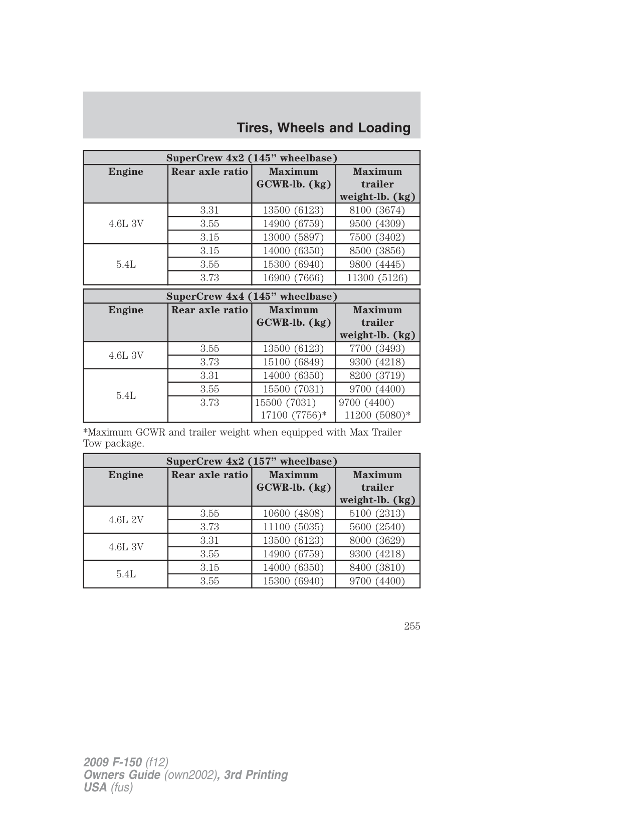
If you use a rental trailer, follow the instructions that the rental agency gives to you.
Do not attach safety chains to the bumper. Trailer brakes
Electric brakes and manual, automatic or surge-type trailer brakes are safe if installed properly and adjusted to the manufacturer’s specifications. The trailer brakes must meet local and Federal regulations.
WARNING: Do not connect a trailer’s hydraulic brake system directly to your vehicle’s brake system. Your vehicle may not
have enough braking power and your chances of having a collision greatly increase.
The braking system of the tow vehicle is rated for operation at the GVWR not GCWR.
###### Integrated trailer brake controller (if equipped)
Your vehicle may be equipped with a fully integrated electronic trailer brake controller (TBC). When used properly, the TBC helps ensure smooth and effective trailer braking by powering the trailer’s electric brakes with a proportional output based on the towing vehicle’s brake pressure.
WARNING: The Ford TBC has only been verified to be compatible with trailers having electric-actuated drum brakes
(one to four axles) and not hydraulic surge or electric-over-hydraulic types. It is the responsibility of the customer to ensure that the trailer brakes are adjusted appropriately, functioning normally and all electric connections are properly made.
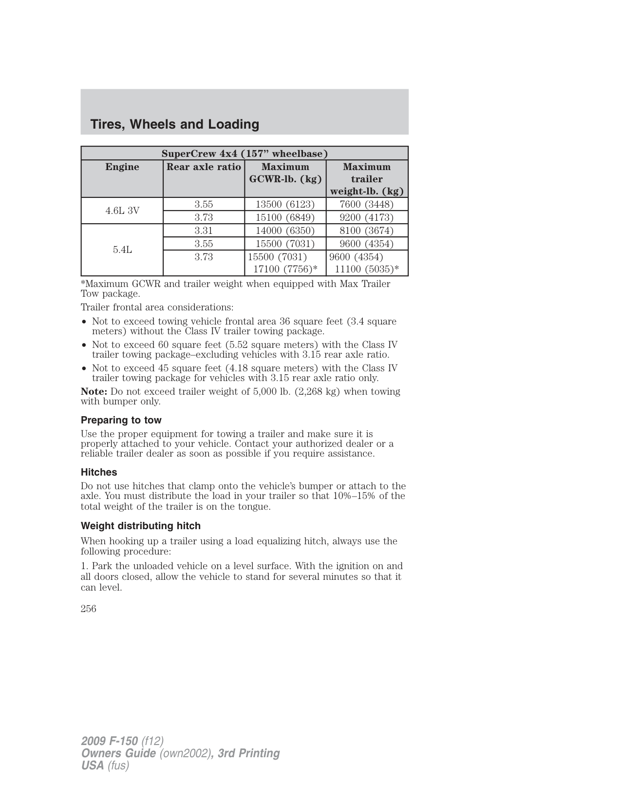
The TBC user interface consists of the following:
• Stop Lamps: Activating the TBC manual control lever will illuminate both the trailer brake lamps and the tow vehicle brake lamps except the Center High-Mount Stop Lamp (presuming proper trailer electrical connection). Pressing the vehicle brake pedal will also illuminate both trailer and vehicle brake lamps.
GAIN: The GAIN setting is used to set the TBC for the specific towing condition and should be changed as towing conditions change. Changes to towing conditions include trailer load, vehicle load, road conditions and weather.
The GAIN should be set to provide the maximum trailer braking assistance while ensuring the trailer wheels do not lock when braking. Locked trailer wheels may lead to trailer instability.
Procedure for adjusting GAIN: Note: This should only be performed in a traffic free environment at speeds of approximately 20–25 mph (30–40 km/h).
Repeat Steps 5 and 6 until the GAIN setting is at a point just below trailer-wheel lockup. If towing a heavier trailer, trailer wheel lockup may not be attainable even with the maximum GAIN setting of 10.
###### Explanation of instrument cluster messages:
The TBC interacts with the instrument cluster message center. These messages, accompanied by a single chime, will be displayed when the TBC determines a malfunction in the trailer connection, TBC system, or in the trailer. These messages are listed below:
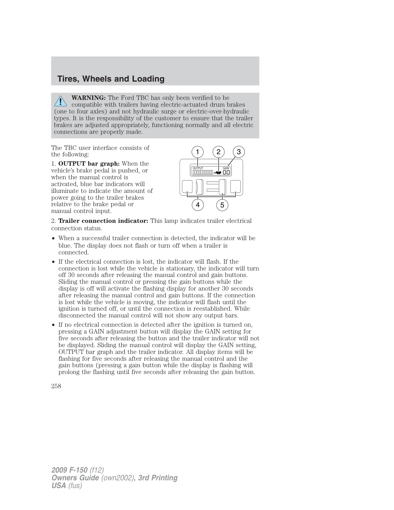
TRAILER DISCONNECTED: This message is displayed when a trailer connection was determined and then a disconnection, either intentionally or unintentionally, has been sensed during a given ignition cycle. It is also displayed if a trailer fault occurs causing the trailer to appear disconnected. This message is also displayed during manual activation without a trailer connected.
###### TRAILER BRAKE MODULE FAULT: This message is displayed in
response to faults sensed by the TBC. In the event this message is seen, please take your vehicle to an authorized dealer for diagnosis and repair. The TBC may still function, but performance may be degraded.
WIRING FAULT ON TRAILER: The TBC is capable of determining certain faults in the vehicle wiring and trailer wiring/brake system. These faults do not mean there is anything wrong with the TBC. This message is displayed when one of the following faults has occurred:
• Short circuit on the electric brake output wire: If the WIRING FAULT ON TRAILER message is displayed with no trailer connected, the problem is with the vehicle wiring from the TBC to the 7–pin connector in the bumper. If the message is only displayed with a trailer connected, the problem is related to the trailer wiring; consult your trailer dealer for assistance. This can be a short to ground (i.e., chaffed wire) or a short to voltage (i.e., a pulled pin on trailer emergency break-away battery) or trailer brakes drawing too much current.
Note: Your TBC can be diagnosed by your authorized dealer to determine exactly which trailer fault has occurred; however, if the fault is with the trailer this diagnosis is not covered under your Ford warranty. Points to Remember:
Trailer lamps Trailer lamps are required on most towed vehicles. Make sure all running lights, brake lights, turn signals and hazard lights are working. Contact your authorized dealer or trailer rental agency for proper instructions and equipment for hooking up trailer lamps. Using a step bumper (if equipped)
The rear bumper is equipped with an integral hitch and only requires a ball with a one inch (25.4 mm) shank diameter. The bumper has a 5,000 lb (2,270 kg) trailer weight and 500 lb (227 kg) tongue weight capacity.
If it is necessary to relocate the trailer hitch ball position, a frame-mounted trailer hitch must be installed.
Driving while you tow When towing a trailer:
If you tow a trailer for long distances, your vehicle will require more frequent service intervals. Refer to your scheduled maintenance information for more information.
Trailer towing tips
Launching or retrieving a boat
Disconnect the wiring to the trailer before backing the trailer into the water. Reconnect the wiring to the trailer after the trailer is removed from the water.
When backing down a ramp during boat launching or retrieval:
• do not allow the static water level to rise above the bottom edge of
the rear bumper.
• do not allow waves to break higher than 6 inches (15 cm) above the
bottom edge of the rear bumper. Exceeding these limits may allow water to enter vehicle components:
Replace the rear axle lubricant any time the axle has been submerged in water. Rear axle lubricant quantities are not to be checked or changed unless a leak is suspected or repair required.
###### RECREATIONAL TOWING
Follow these guidelines if you have a need for recreational (RV) towing. An example of recreational towing would be towing your vehicle behind a motorhome. These guidelines are designed to ensure that your transmission is not damaged.
Note: Put your climate control system in recirculated air mode to prevent exhaust fumes from entering the vehicle. Refer to the Climate controls chapter for more information.
2WD vehicles: Do not tow your vehicle with any wheels on the ground, as vehicle or transmission damage may occur. It is recommended to tow your vehicle with all four (4) wheels off the ground such as when using a car-hauling trailer. Otherwise, no recreational towing is permitted.
###### 4WD vehicles equipped with manual-shift transfer case:
The transfer case N (Neutral) position overrides the transmission and puts the vehicle in neutral regardless of transmission gearshift lever position. The vehicle can move forward or backward. This position should only be used when towing the vehicle.
WARNING: Do not leave the vehicle unattended with the transfer case in the N (Neutral) position. Always set the parking
brake fully and turn off the ignition when leaving the vehicle.
After reaching the destination, you must place your vehicle’s 4x4 gearshift lever in gear (2H, 4H or 4L).
In case of a roadside emergency with a disabled vehicle, see Wrecker towing in the Roadside Emergencies chapter.
4WD vehicles equipped with an electronic-shift transfer case: Do not tow your vehicle with any wheels on the ground, as vehicle or transmission damage may occur. It is recommended to tow your vehicle with all four (4) wheels off the ground such as when using a car-hauling trailer. Otherwise, no recreational towing is permitted.
In case of a roadside emergency with a disabled vehicle, see Wrecker towing in the Roadside Emergencies chapter.
STARTING Positions of the ignition
Note: The ignition key cannot be removed from the ignition unless the gearshift lever is securely latched in P (Park).
Preparing to start your vehicle Engine starting is controlled by the powertrain control system. This system meets all Canadian interference-causing equipment standard requirements regulating the impulse electrical field strength of radio noise. When starting a fuel-injected engine, don’t press the accelerator before or during starting. Only use the accelerator when you have difficulty starting the engine. For more information on starting the vehicle, refer to Starting the engine in this chapter.
WARNING: Extended idling at high engine speeds can produce very high temperatures in the engine and exhaust system,
creating the risk of fire or other damage.
WARNING: Do not park, idle, or drive your vehicle in dry grass or other dry ground cover. The emission system heats up the
engine compartment and exhaust system, which can start a fire.
WARNING: Do not start your vehicle in a closed garage or in other enclosed areas. Exhaust fumes can be toxic. Always open
the garage door before you start the engine. See Guarding against exhaust fumes in this chapter for more instructions.
WARNING: If you smell exhaust fumes inside your vehicle, have your dealer inspect your vehicle immediately. Do not drive if you
smell exhaust fumes.
###### Important safety precautions
A computer system controls the engine’s idle revolutions per minute (RPM). When the engine starts, the idle RPM runs higher than normal in order to warm the engine. If the engine idle speed does not slow down automatically, have the vehicle checked. If the vehicle is operated in a heavy snow storm or blowing snow conditions, the engine air induction may become partially clogged with snow and/or ice. If this occurs the engine may experience a significant reduction in power output. At the earliest opportunity, clear all snow and/or ice away from the air induction inlet. Do not allow the vehicle to idle for more than 10 minutes at the higher engine RPM.
Before starting the vehicle:
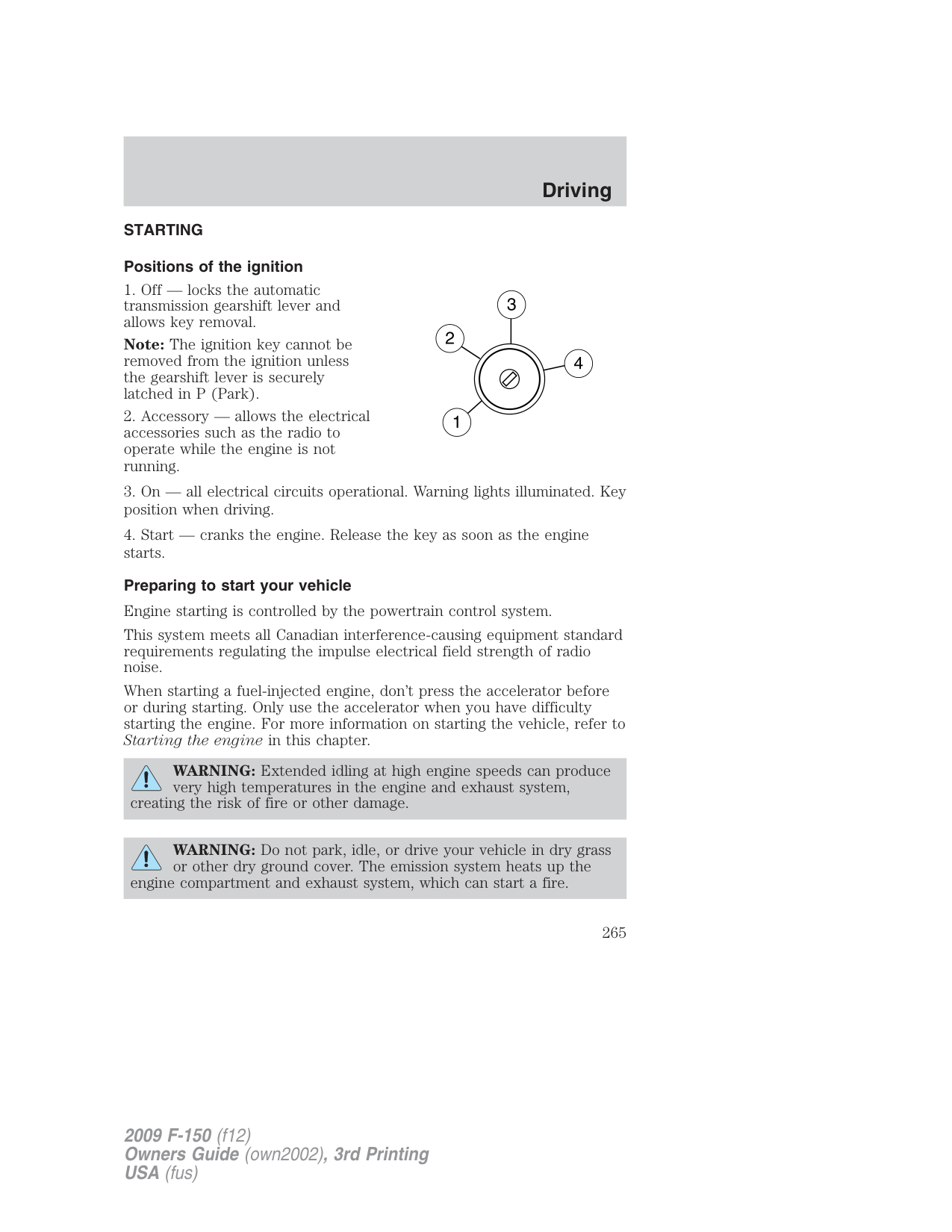
############ BRAKE
Some warning lights will briefly illuminate. See Warning lights and chimes in the Instrument Cluster chapter for more information regarding the warning lights.
###### Starting the engine
Note: If the engine does not start on the first try, turn the key to the off position, wait 10 seconds and try Step 2 again. If the engine still fails to start, press the accelerator to the floor and try Step 2 again, keeping the accelerator on the floor until the engine begins to accelerate above cranking speeds; this will allow the engine to crank with the fuel shut off in case the engine is flooded with fuel.
###### Cold weather starting (flexible fuel vehicles only)
The starting characteristics of all grades of E85 ethanol make it unsuitable for use when ambient temperatures fall below 0°F (-18°C).
Consult your fuel distributor for the availability of winter grade ethanol. As the outside temperature approaches freezing, ethanol fuel distributors should supply winter grade ethanol (same as with unleaded gasoline). If summer grade ethanol is used in cold weather conditions, 0°F to 32°F (-18°C to 0°C), you may experience increased cranking times, rough idle or hesitation until the engine has warmed up.
You may experience a decrease in peak performance when the engine is cold when operating on E85 ethanol. Do not crank the engine for more than 10 seconds at a time as starter damage may occur. If the engine fails to start, turn the key to off and wait 30 seconds before trying again. Do not use starting fluid such as ether in the air intake system. Such fluid could cause immediate explosive damage to the engine and possible personal injury. If you should experience cold weather starting problems on E85 ethanol, and neither an alternative brand of E85 ethanol nor an engine block heater is available, the addition of unleaded gasoline to your tank will improve cold starting performance. Your vehicle is designed to operate on E85 ethanol alone, unleaded gasoline alone, or any mixture of the two. See Choosing the right fuel in the Maintenance and Specifications chapter for more information on ethanol.
If the engine fails to start using the preceding instructions (flexible fuel vehicles only)
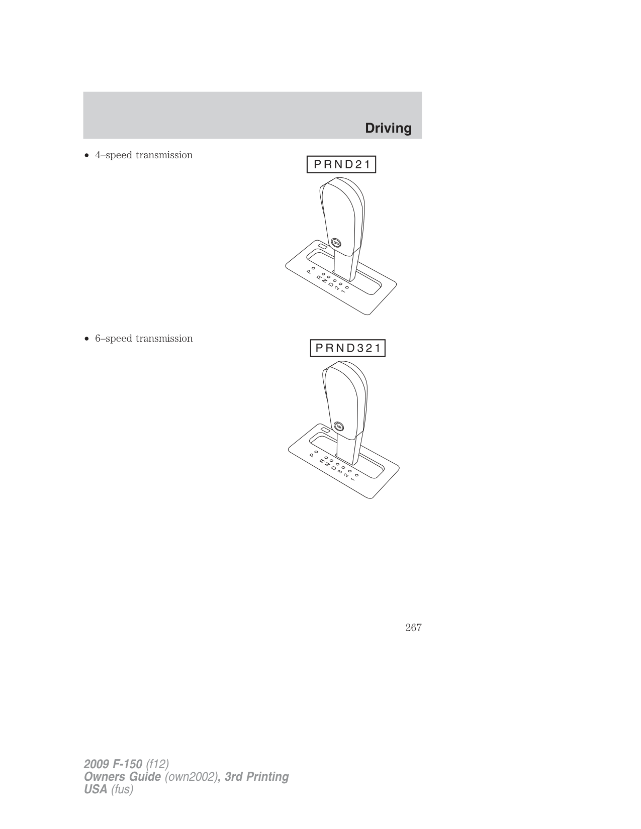
###### Guarding against exhaust fumes
Carbon monoxide is present in exhaust fumes. Take precautions to avoid its dangerous effects.
WARNING: If you smell exhaust fumes inside your vehicle, have your dealer inspect your vehicle immediately. Do not drive if you
smell exhaust fumes.
###### Important ventilating information
If the engine is idling while the vehicle is stopped for a long period of time, open the windows at least one inch (2.5 cm) or adjust the heating or air conditioning to bring in fresh air.
###### ENGINE BLOCK HEATER (IF EQUIPPED)
An engine block heater warms the engine coolant which aids in starting and allows the heater/defroster system to respond quickly. If your vehicle is equipped with this system, your equipment includes a heater element which is installed in your engine block and a wire harness which allows the user to connect the system to a grounded 120 volt a/c electrical source. The block heater system is most effective when outdoor temperatures reach below 0°F (-18°C).
For flexible fuel vehicles, if operating with E85 ethanol, an engine block heater must be used if ambient temperature is below 0°F (-18°C).
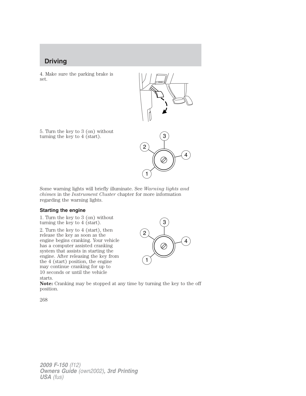
See Cold weather starting in the Driving chapter for more information on starting with ethanol.
WARNING: Failure to follow engine block heater instructions could result in property damage or physical injury.
WARNING: To reduce the risk of electrical shock, do not use your heater with ungrounded electrical systems or two-pronged
(cheater) adapters.
Prior to using the engine block heater, follow these recommendations for proper and safe operation:
###### How to use the engine block heater
Ensure the receptacle terminals are clean and dry prior to use. To clean them, use a dry cloth.
Depending on the type of factory installed equipment, your engine block heater system may consume anywhere between 400 watts or 1000 watts of power per hour. Your factory installed block heater system does not have a thermostat; however, maximum temperature is attained after approximately three hours of operation. Block heater operation longer than 3 hours will not improve system performance and will unnecessarily use additional electricity.
Make sure system is unplugged and properly stowed before driving the vehicle. While not in use, make sure the protective cover seals the prongs of the engine block heater cord plug.
BRAKES Occasional brake noise is normal. If a metal-to-metal, continuous grinding or continuous squeal sound is present, the brake linings may be worn-out and should be inspected by an authorized dealer. If the vehicle has continuous vibration or shudder in the steering wheel while braking, the vehicle should be inspected by an authorized dealer. Refer to Brake system warning light in the Instrument Cluster chapter for information on the brake system warning light.
P! BRAKE
###### Four-wheel anti-lock brake system (ABS)
Your vehicle is equipped with an Anti-lock Braking System (ABS). This system helps you maintain steering control during emergency stops by keeping the brakes from locking. Noise from the ABS pump motor and brake pedal pulsation may be observed during ABS braking and the brake pedal may suddenly travel a little farther as soon as ABS braking is done and normal brake operation resumes. These are normal characteristics of the ABS and should be no reason for concern.
###### Using ABS
When hard braking is required, apply continuous force on the brake pedal; do not pump the brake pedal since this will reduce the effectiveness of the ABS and will increase your vehicle’s stopping distance. The ABS will be activated immediately, allowing you to retain steering control during hard braking and on slippery surfaces. However, the ABS does not decrease stopping distance.
###### ABS warning lamp
The ABS lamp in the instrument cluster momentarily illuminates when the ignition is turned on. If the light does not illuminate during start up, remains on or flashes, the ABS may be disabled and may need to be serviced.
ABS
Even when the ABS is disabled, normal braking is still effective. If your BRAKE warning lamp illuminates with the parking brake released, have your brake system serviced immediately.
P! BRAKE
###### Parking brake
To set the parking brake (1), press the parking brake pedal down until the pedal stops.
The BRAKE warning lamp will illuminate and will remain illuminated until the parking brake is released.
P! BRAKE
To release, pull the lever (2).
WARNING: Always set the parking brake fully and make sure that the gearshift is securely latched in P (Park) (automatic
transmission) or in 1 (First) (manual transmission).
###### ADVANCETRAC WITH ROLL STABILITY CONTROL™ (RSC ) STABILITY ENHANCEMENT SYSTEM
WARNING: Vehicle modifications involving braking system, aftermarket roof racks, suspension, steering system, tire
construction and/or wheel/tire size may change the handling characteristics of the vehicle and may adversely affect the the performance of the AdvanceTrac with RSC system. In addition, installing any stereo loudspeakers may interfere with and adversely affect the AdvanceTrac with RSC system. Install any aftermarket stereo loudspeaker as far as possible from the front center console, the tunnel, and the front seats in order to minimize the risk of interfering with the AdvanceTrac with RSC sensors. Reducing the effectiveness of the AdvanceTrac with RSC system could lead to an increased risk of loss of vehicle control, vehicle rollover, personal injury and death.
WARNING: Remember that even advanced technology cannot defy the laws of physics. It’s always possible to lose control of a
vehicle due to inappropriate driver input for the conditions. Aggressive driving on any road condition can cause you to lose control of your vehicle increasing the risk of personal injury or property damage. Activation of the AdvanceTrac with RSC system is an indication that at least some of the tires have exceeded their ability to grip the road; this could reduce the operator’s ability to control the vehicle, potentially resulting in a loss of vehicle control, vehicle rollover, personal injury and death. If your AdvanceTrac with RSC system activates, SLOW DOWN.
WARNING: If a failure has been detected within the AdvanceTrac with RSC system, the sliding car icon will
illuminate steadily. Verify that the AdvanceTrac with RSC system is not manually disabled (push the AdvanceTrac with RSC “Off “ control button located on the center of the instrument panel). If the
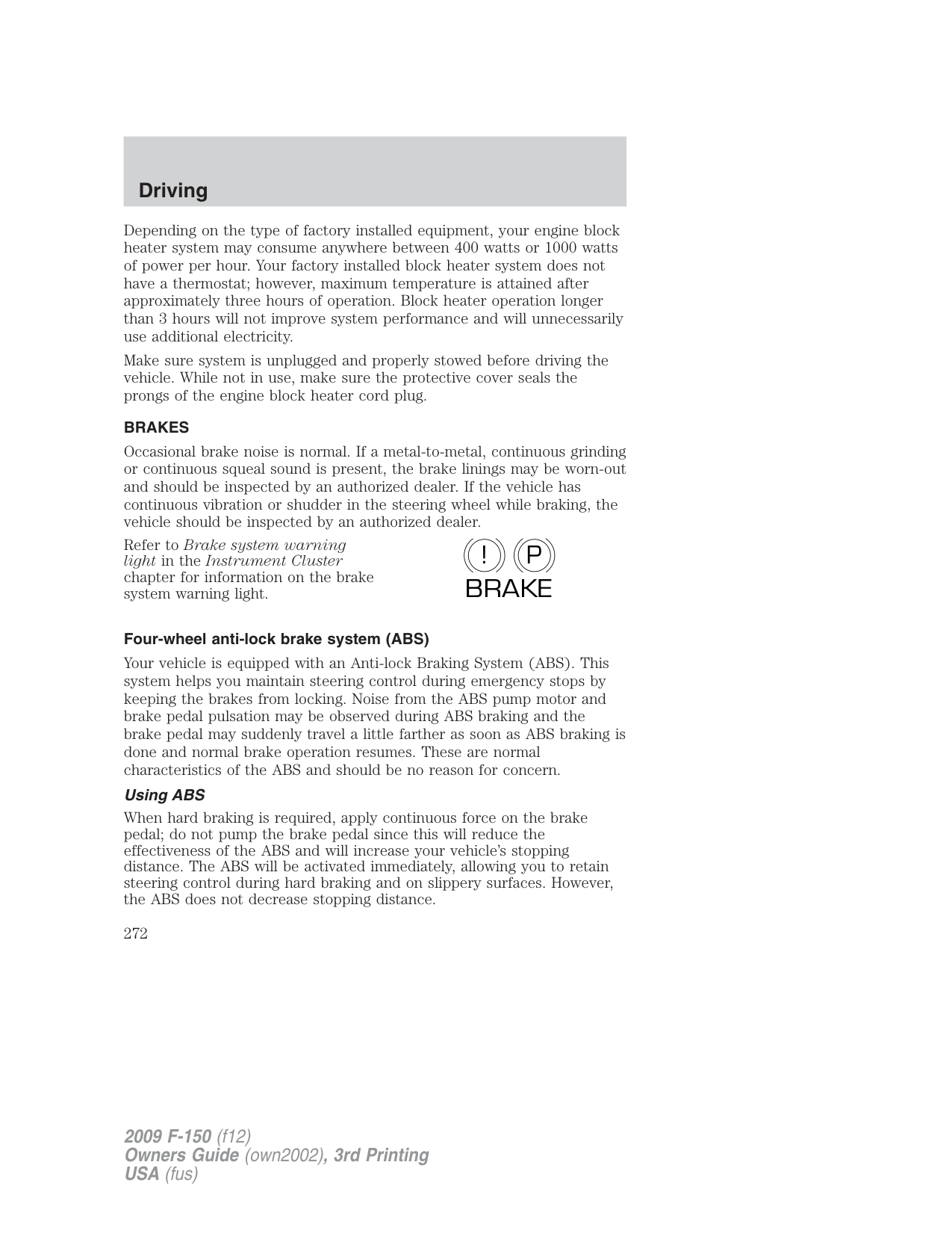
sliding car icon still illuminates steadily, have the system service by an authorized dealer immediately. Operating your vehicle with AdvanceTrac with RSC disabled could lead to an increased risk of loss of vehicle control, vehicle rollover, personal injury and death.
The AdvanceTrac with RSC system provides the following stability enhancement features for certain driving situations:
The AdvanceTrac with RSC system automatically enables each time the engine is started. All features of the AdvanceTrac with RSC system (TCS, ESC, and RSC ) are active and monitor the vehicle from start-up. However, the system will only intervene if the driving situation requires it.
The AdvanceTrac with RSC system includes an AdvanceTrac with RSC Off control button on the center of the instrument panel, and a “sliding car” icon in the instrument cluster. The “sliding car” icon in the instrument cluster will illuminate if a driving situation causes the AdvanceTrac with RSC system to operate. If the “sliding car” icon illuminates steadily, verify that the AdvanceTrac with RSC system is not manually disabled by pressing the AdvanceTrac with RSC Off button located on the center stack of the instrument panel. If the “sliding car” icon remains steadily illuminated, have the system serviced by an authorized dealer immediately. When AdvanceTrac with RSC performs a normal system self-check, some drivers may notice a slight movement of the brake, and/or a rumble, grunting, or grinding noise after startup and when driving off. When an event occurs that activates AdvanceTrac with RSC you may experience the following:
| | |---|
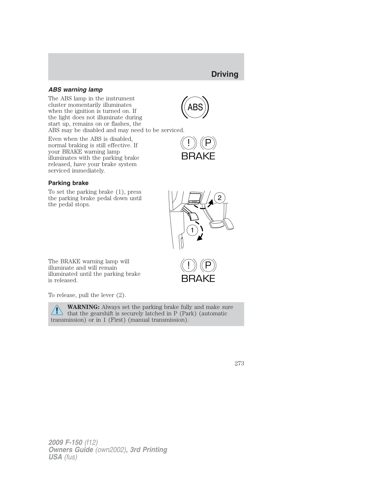
Traction Control is a driver aid feature that helps your vehicle maintain traction of the wheels, typically when driving on slippery and/or hilly road surfaces, by detecting and controlling wheel spin.
Excessive wheel spin is controlled in two ways, which may work separately or in tandem: Engine Traction Control and Brake Traction Control. Engine Traction Control works to limit drive-wheel spin by momentarily reducing engine power. Brake Traction Control works to limit wheel spin by momentarily applying the brakes to the wheel that is slipping. Traction Control is most active at low speeds.
During Traction Control events the “sliding car” icon in the instrument cluster will flash. If the Traction Control system is activated excessively in a short period of time, the braking portion of the system may become temporarily disabled to allow the brakes to cool down. In this situation, Traction Control will use only engine power reduction or transfer to help control the wheels from over-spinning. When the brakes have cooled down, the system will regain all features. Anti-lock braking, RSC , and ESC are not affected by this condition and will continue to function during the cool-down period. The Engine Traction Control and Brake Traction Control system may be deactivated in certain situations. See the Switching Off AdvanceTrac with RSC section following. Electronic Stability Control (ESC)
Electronic Stability Control (ESC) may enhance your vehicle’s directional stability during adverse maneuvers, for example when cornering severely or avoiding objects in the roadway. ESC operates by applying brakes to one or more of the wheels individually and, if necessary, reducing engine power if the system detects that the vehicle is about to skid or slide laterally.
During Electronic Stability Control events the “sliding car” icon in the instrument cluster will flash. Certain adverse driving maneuvers may activate the Electronic Stability Control system, which include but are not limited to:
The Electronic Stability Control system may be deactivated in certain situations. See the Switching Off AdvanceTrac with RSC section following.
###### Roll Stability Control™ (RSC )
Roll Stability Control (RSC ) may help to maintain roll stability of the vehicle during adverse maneuvers. RSC operates by detecting the vehicle’s roll motion and the rate at which it changes and by applying the brakes to one or more wheels individually.
During an event that activates the Roll Stability Control™ (RSC )the “sliding car” icon in the instrument cluster will flash.
Certain adverse driving maneuvers may activate the Roll Stability Control system, which include:
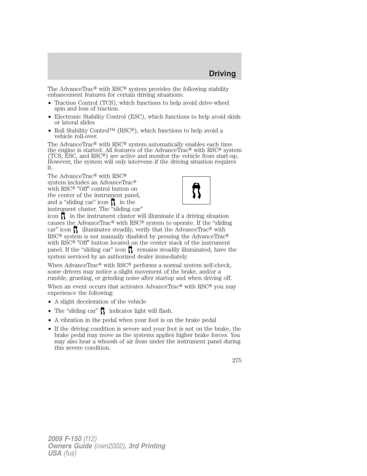
The Roll Stability Control system may be deactivated in certain situations. See the Switching Off AdvanceTrac with RSC section following.
###### Switching Off AdvanceTrac with RSC
If the vehicle is stuck in snow, mud or sand, and seems to lose engine power, switching off certain features of the AdvanceTrac with RSC system may be beneficial because the wheels are allowed to spin. This will restore full engine power and will enhance momentum through the obstacle. To switch off the AdvanceTrac with RSC system press the AdvanceTrac with RSC Off button. Full features of the AdvanceTrac with RSC system can be restored by pressing the AdvanceTrac with RSC Off button again or by turning off and restarting the engine.
If you switch off the AdvanceTrac with RSC system, the sliding car icon will illuminate steadily. Pressing the AdvanceTrac with RSC
Off button again will turn off the sliding car icon .
In R (Reverse), ABS and the Engine and Brake Traction Control features will continue to function; however, ESC and RSC are disabled.
|AdvanceTrac with RSC Features|AdvanceTrac with RSC Features|AdvanceTrac with RSC Features|AdvanceTrac with RSC Features|AdvanceTrac with RSC Features| |---|---|---|---|---| |Button functions|“Sliding car” icon
|RSC|ESC|Traction Control| |Default at start-up|Illuminated during bulb check|Enabled|Enabled|Enabled| |Button pressed momentarily|Illuminated during bulb check|Enabled|Enabled|Disabled|
|Button pressed and held for more than five seconds at vehicle speed under 35 mph (56 km/h)|Flashes then illuminated solid|Disabled|Disabled|Disabled| |Vehicle speed exceeds 35 mph (56 km/h) after button is pressed and held for more than five seconds|Illuminated solid|Enabled|Enabled|Disabled| |Button pressed again after deactivation|Not illuminated|Enabled|Enabled|Enabled|
###### Trailer Sway Control
Your vehicle may be equipped with trailer sway control. When properly equipped, trailer sway control will use the vehicle’s AdvanceTrac with RSC system to detect and help reduce trailer sway by applying brake force at individual wheels and, if necessary, by reducing engine power.
WARNING: Trailer sway control does not prevent a trailer from swaying, it mitigates the sway from increasing once it has
occurred. If you are experiencing trailer sway it is likely that the trailer is improperly loaded for the correct tongue weight or the speed of the vehicle and trailer is too high. Pull the vehicle-trailer over to a safe location to check the trailer weight distribution and tongue load and reduce speed to a safe level while towing. If trailer sway is experienced, SLOW DOWN.
During Trailer Sway Control events the skidding car icon in the instrument cluster will flash momentarily. The message center will also display TRAILER SWAY REDUCE SPEED. In some cases when trailer sway is detected, the vehicle speed is too high and may be above a speed at which trailer sway will not grow continuously. This may cause the system to activate multiple times, causing a gradual reduction in speed. Note: The trailer sway control will only activate at speeds greater than 40 mph (64 km/h). Disabling Trailer Sway Control
Trailer sway control can be disabled during any key cycle. See Trailer Sway Control under the Message center in the Driver Controls chapter. Note that regardless of chosen enable state, Trailer Sway Control will be re-enabled at each new key cycle.
WARNING: Turning off Trailer Sway Control increases the risk of loss of vehicle control, serious injury, or death. Ford does not
recommend disabling this feature except in situations where speed reduction may be detrimental (e.g., hill climbing), the driver has significant trailer towing experience, and can control trailer sway and maintain safe operation.
STEERING To help prevent damage to the power steering system:
If the power steering system breaks down (or if the engine is turned off), you can steer the vehicle manually, but it takes more effort.
If the steering wanders or pulls, check for:
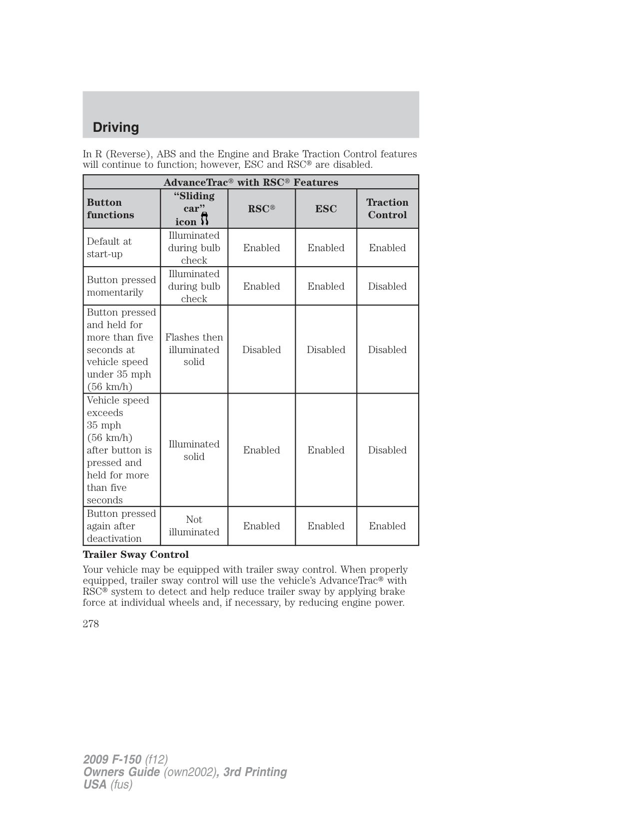
A high crown in the road or high crosswinds may also make the steering seem to wander/pull.
###### LIMITED-SLIP AXLE (IF EQUIPPED)
This axle provides added traction on slippery surfaces, particularly when one wheel is on a poor traction surface. Under normal conditions, the Limited-slip axle functions like a standard rear axle. The axle may exhibit a slight noise or vibration in tight turns with low vehicle speed. This is normal behavior and indicates the axle is working.
###### Electronic locking differential (ELD) axle (if equipped)
This axle provides added traction on slippery and/or off road surfaces, particularly when one wheel is on a poor traction surface. In normal driving conditions the rear axle function as a standard axle. The ELD may be locked or unlocked by the vehicle operator. Refer to Four-wheel drive (4WD) operation section in this chapter for further detail on ELD function and usage. When the axle is unlocked it will function like a standard rear axle. When the axle is locked it will not allow the rear wheels to rotate at different speeds when turning. The ELD axle is not recommended for use on good traction surfaces such as dry pavement. Doing so may result in abnormal driving behavior while cornering and excessive tire wear.
###### PREPARING TO DRIVE
WARNING: Utility vehicles have a significantly higher rollover rate than other types of vehicles.
WARNING: In a rollover crash, an unbelted person is significantly more likely to die than a person wearing a seat belt.
Utility vehicles and trucks have larger tires and increased ground clearance, giving the vehicle a higher center of gravity than a passenger car.
WARNING: Vehicles with a higher center of gravity such as utility vehicles and trucks handle differently than vehicles with a lower center of gravity. Utility vehicles and trucks are not designed for cornering at speeds as high as passenger cars any more than low-slung sports cars are designed to perform satisfactorily under off-road conditions. Avoid sharp turns, excessive speed or abrupt maneuvers in these vehicles. Failure to drive cautiously could result in an increased risk of loss of vehicle control, vehicle rollover, personal injury and death.
WARNING: Loaded vehicles, with a higher center of gravity, may handle differently than unloaded vehicles. Do not overload
your vehicle and use extra precautions, such as driving at slower speeds, avoiding abrupt steering changes and allowing for increased stopping distance, when driving a heavily loaded vehicle. Over-loading or loading the vehicle improperly can deteriorate handling capability and contribute to loss of vehicle control and vehicle rollover.
AUTOMATIC TRANSMISSION OPERATION Brake-shift interlock - column-shift transmission
This vehicle is equipped with a park/brake-shift interlock feature that prevents the gearshift lever from being moved from P (Park) when the ignition is in the on position unless the brake pedal is pressed.
If you cannot move the gearshift lever out of P (Park) with ignition in the on position and the brake pedal pressed, it is possible that a fuse has blown or the vehicle’s brakelamps are not operating properly. Refer to Fuses and relays in the Roadside Emergencies chapter.
If the fuse is not blown, perform the following procedure: Note: The following procedure is easier to perform when the steering column is adjusted to the full up position. Refer to Tilt steering wheel in the Driver Controls chapter.
Note: After the transmission is shifted to N (Neutral), it is easier to reinstall the cover when the column is in the middle or lower tilt position.
WARNING: Do not drive your vehicle until you verify that the brakelamps are working.
WARNING: Always set the parking brake fully and make sure the gearshift is latched in P (Park). Turn the ignition to the off
position and remove the key whenever you leave your vehicle.
WARNING: If the parking brake is fully released, but the brake warning lamp remains illuminated, the brakes may not be
working properly. See your authorized dealer.
###### Brake-shift interlock – floor-shift transmission
This vehicle is equipped with a brake-shift interlock feature that prevents the gearshift lever from being moved from P (Park) when the ignition is in the ON position unless the brake pedal is pressed.
If you cannot move the gearshift lever out of P (Park) with ignition in the on position and the brake pedal pressed, or when the ignition is in the off position, it is possible that a fuse has blown or the vehicle’s brakelamps are not operating properly. Refer to Fuses and relays in the Roadside Emergencies chapter.
If the fuse is not blown, perform the following procedure:
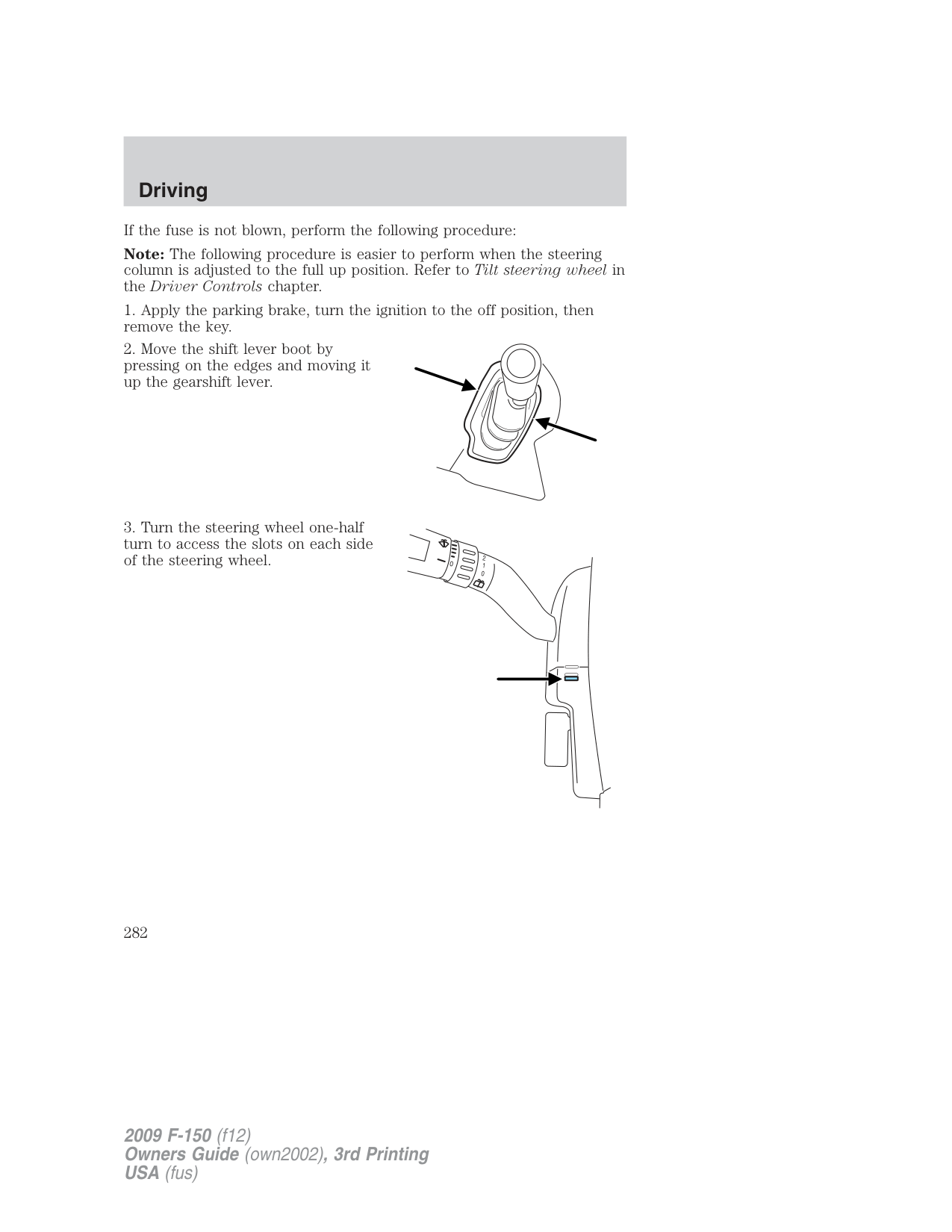
WARNING: Do not drive your vehicle until you verify that the brakelamps are working.
WARNING: Always set the parking brake fully and make sure the gearshift is latched in P (Park). Turn the ignition to the off
position and remove the key whenever you leave your vehicle.
WARNING: If the parking brake is fully released, but the brake warning lamp remains illuminated, the brakes may not be
working properly. See your authorized dealer.
Understanding the gearshift positions of the 4–speed automatic transmission
Your vehicle has been designed to improve fuel economy by reducing fuel usage during coasting or deceleration. When you take your foot off the accelerator pedal and the vehicle begins to slow down the torque converter clutch locks up and aggressively shuts off fuel flow to the engine while decelerating. This fuel economy benefit may be perceived as a light to medium braking sensation when removing your foot from the accelerator pedal.
Your vehicle’s automatic transmission is equipped with a special shift strategy that ensures maximum heater performance during cold weather operation. When ambient temperature is 23°F (–5°C) or below and the engine coolant temperature is below 100°F (38°C), light throttle upshifts may be slightly delayed. Once the engine coolant temperature reaches 160°F (71°C) the normal shift strategy will resume. This is normal operation and will not affect the function or the durability of the transmission.
If the normal shift strategy does not resume once the engine coolant temperature reaches the normal operating temperature, or if the downshifts and other throttle conditions do not function normally, see your authorized dealer as soon as possible.
P (Park)
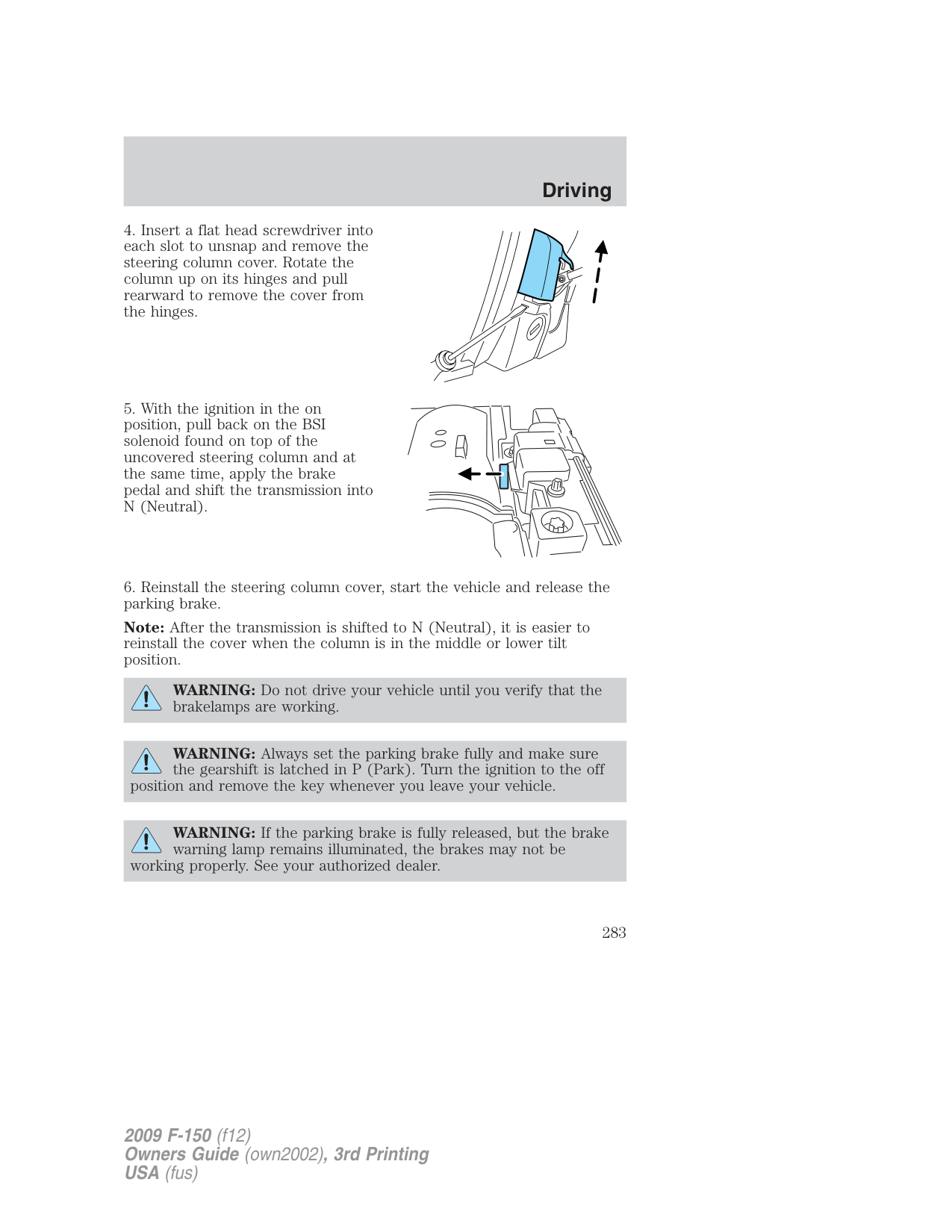
This position locks the transmission and prevents the rear wheels from turning.
To put your vehicle in gear:
WARNING: Always set the parking brake fully and make sure the gearshift is latched in P (Park). Turn the ignition to the off
position and remove the key whenever you leave your vehicle.
R (Reverse) With the gearshift lever in R (Reverse), the vehicle will move backward. Always come to a complete stop before shifting into and out of R (Reverse). N (Neutral)
With the gearshift lever in N (Neutral), the vehicle can be started and is free to roll. Hold the brake pedal down while in this position.
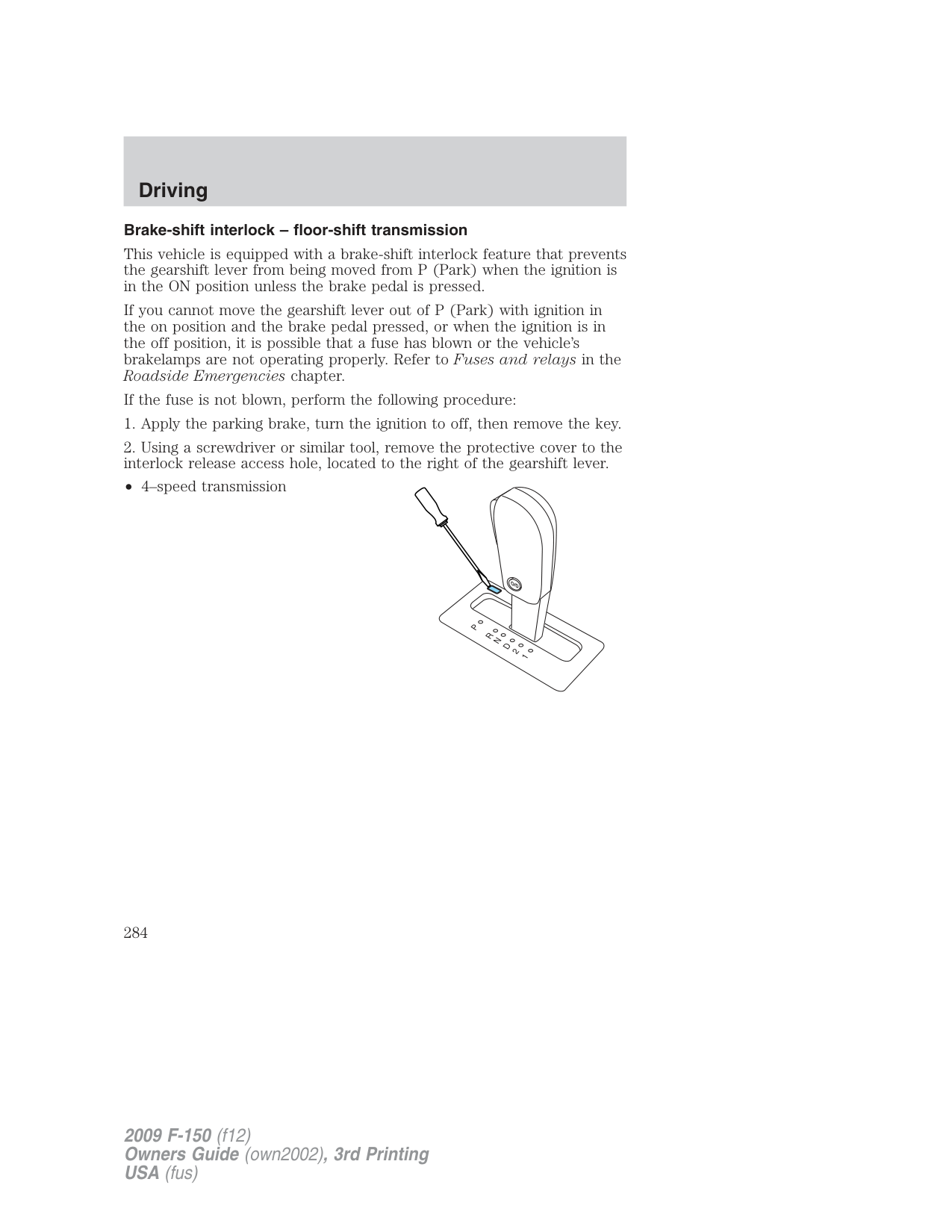
###### D (Overdrive)
The normal driving position for the best fuel economy. Transmission operates in gears one through four.
Overdrive can be deactivated by pressing the transmission control switch on the end of the gearshift lever (column-shift transmission) or on the gearshift bezel (floor-shift transmission).
The transmission control indicator (TCIL) will illuminate on the instrument cluster.
Drive (not shown) Drive is activated when the transmission control switch is pressed.
O/D OFF
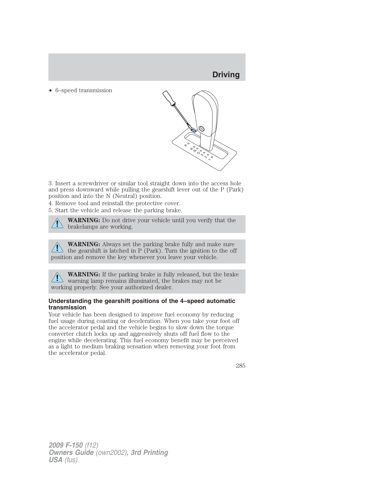
and out of overdrive occurs, hilly terrain, heavy loads, trailer towing and when engine braking is required.
###### 1 (First)
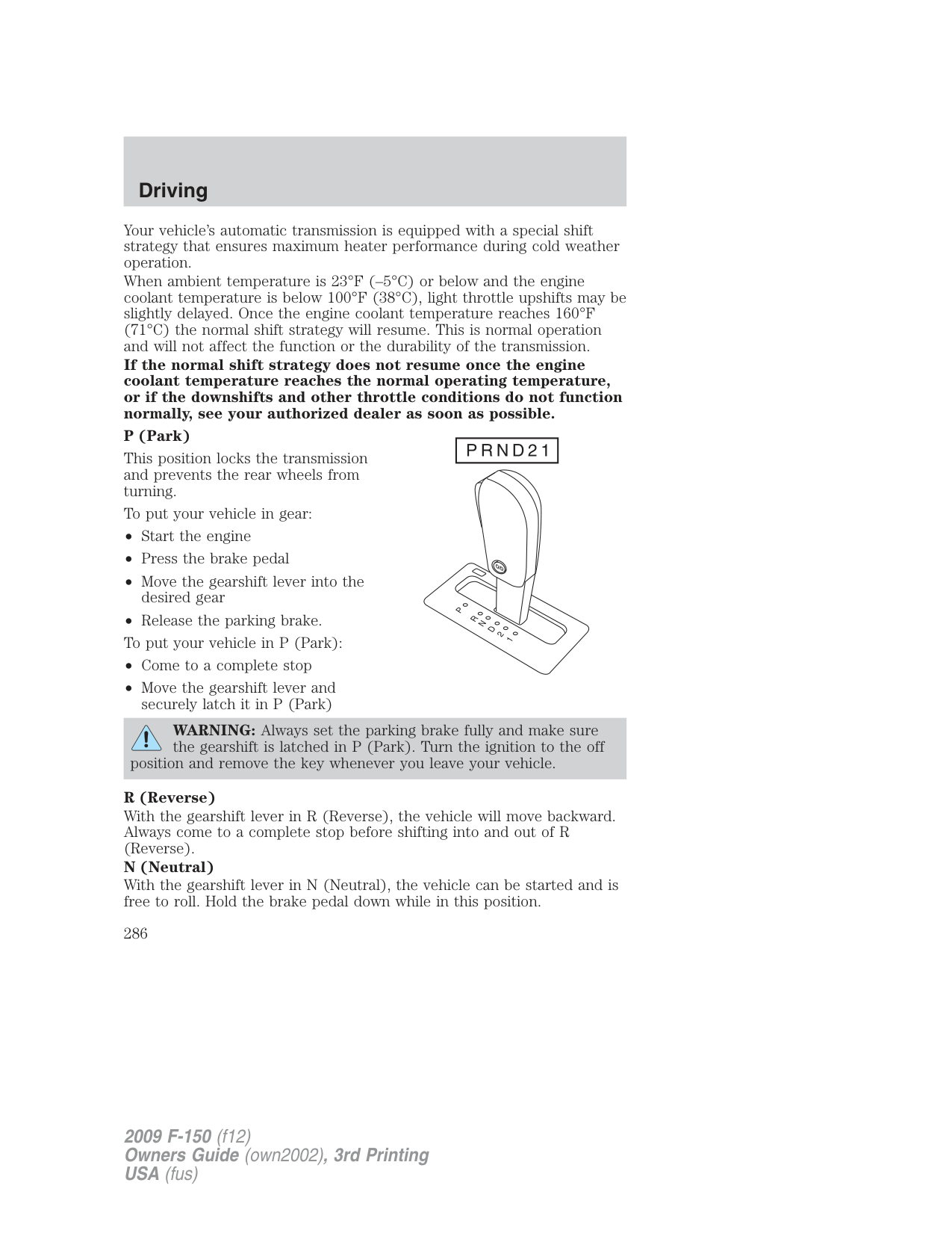
###### Driving with a 6–speed automatic transmission
Your vehicle has been designed to improve fuel economy by reducing fuel usage during coasting or deceleration. When you take your foot off the accelerator pedal and the vehicle begins to slow down the torque converter clutch locks up and aggressively shuts off fuel flow to the engine while decelerating. This fuel economy benefit may be perceived as a light to medium braking sensation when removing your foot from the accelerator pedal.
This vehicle is equipped with an Adaptive Transmission Shift Strategy. The Adaptive Transmission Shift Strategy offers the optimal transmission operation and shift quality. When the engine is turned off, the shift data which includes the adaptive information will be stored automatically in
the Powertrain Control Module (PCM) and Transmission Control Module (TCM). If the battery is disconnected for any reason, the stored information from the last time the key was turned to off will be read. This way, no information will be lost with any battery removal or battery disconnect.
###### P (Park)
This position locks the transmission and prevents the rear wheels from turning.
To put your vehicle in gear:
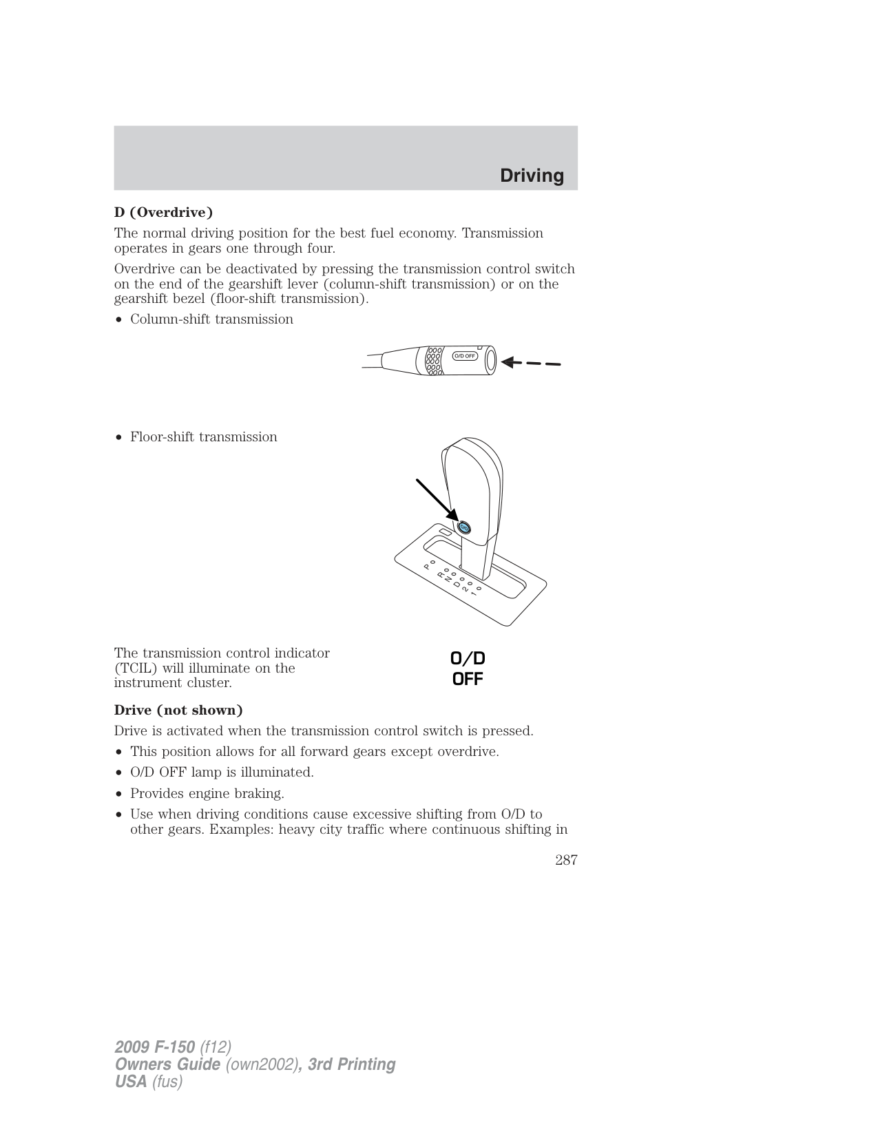
WARNING: Always set the parking brake fully and make sure the gearshift is latched in P (Park). Turn the ignition to the off
position and remove the key whenever you leave your vehicle.
###### R (Reverse)
With the gearshift lever in R (Reverse), the vehicle will move backward. Always come to a complete stop before shifting into and out of R (Reverse).
###### N (Neutral)
With the gearshift lever in N (Neutral), the vehicle can be started and is free to roll. Hold the brake pedal down while in this position.
###### D (Overdrive) with Tow/Haul Off
The normal driving position for the best fuel economy. Transmission operates in gears one through six.
D (Overdrive) with Tow/Haul On The Tow/Haul feature improves transmission operation when towing a trailer or a heavy load. All transmission gear ranges are available when using Tow/Haul. Tow/Haul can be activated by pressing the transmission control switch on the end of the gearshift lever (column-shift transmission) or on the side of the gearshift lever (floor-shift transmission).
The TOW HAUL indicator light will illuminate in the instrument cluster.
Tow/Haul delays upshifts to reduce frequency of transmission shifting. Tow/Haul also provides engine braking in all forward gears when the transmission is in the D (Overdrive) position; this engine braking will slow the vehicle and assist the driver in controlling the vehicle when descending a grade. Depending on driving conditions and load conditions, the transmission may downshift, slow the vehicle and control the vehicle speed when descending a hill, without the accelerator pedal being pressed. The amount of downshift braking provided will vary based upon the amount the brake pedal is depressed. To deactivate the Tow/Haul feature and return to normal driving mode, press the button on the end of the gearshift lever. The TOW HAUL light will no longer be illuminated.
When you shut-off and restart the engine, the transmission will automatically return to normal D (Overdrive) mode (Tow/Haul OFF).
WARNING: Do not use the Tow/Haul feature when driving in icy or slippery conditions as the increased engine braking can cause
the rear wheels to slide and the vehicle to swing around with the possible loss of vehicle control.
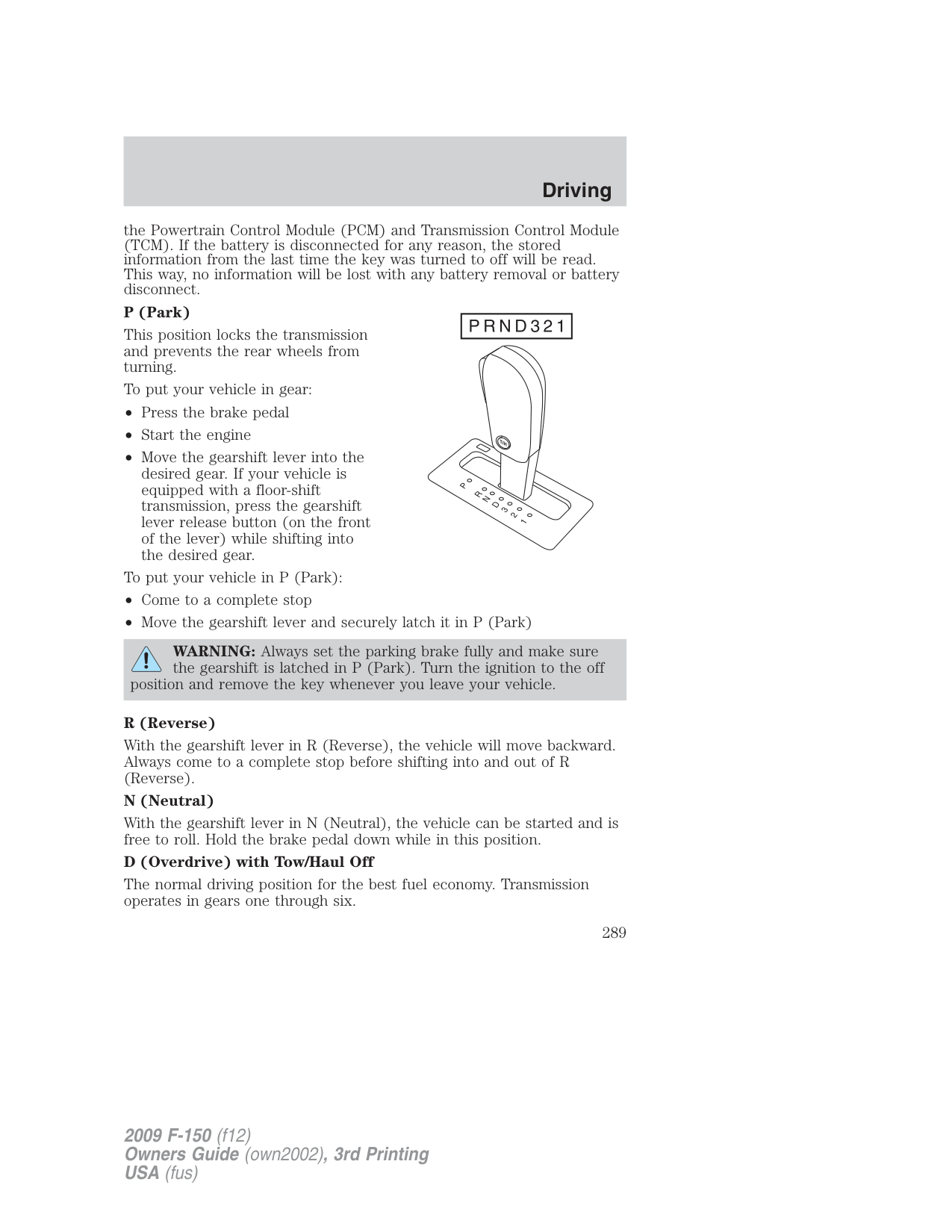
Used for improved traction on slippery roads. Selecting 3 (Third) provides engine braking.
Use 2 (Second) to start-up on slippery roads or to provide additional engine braking on downgrades.
###### 1 (First)
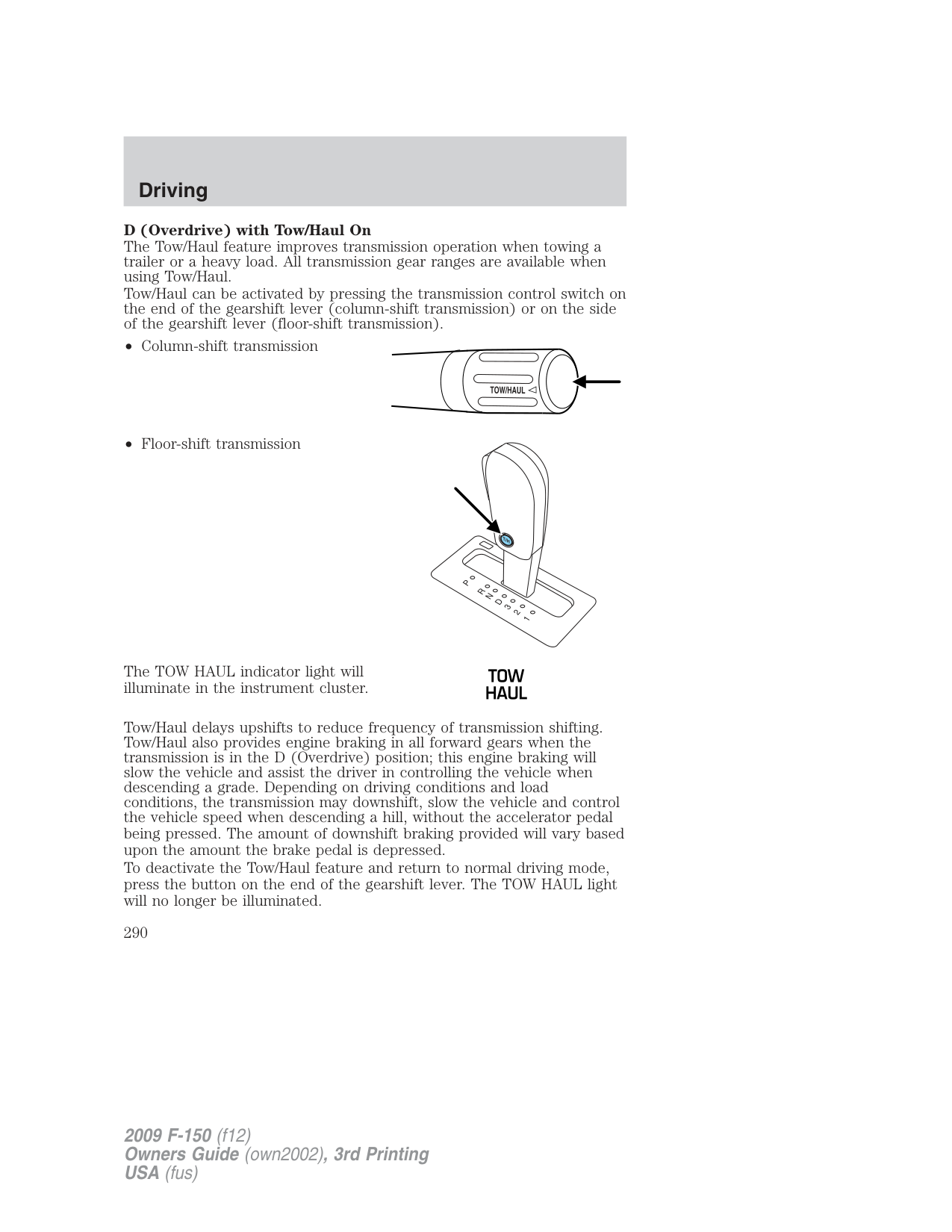
If your vehicle gets stuck in mud or snow, it may be rocked out by shifting between forward and reverse gears, stopping between shifts in a steady pattern. Press lightly on the accelerator in each gear.
Do not rock the vehicle if the engine is not at normal operating temperature or damage to the transmission may occur.
Do not rock the vehicle for more than a minute or damage to the transmission and tires may occur, or the engine may overheat.
###### REVERSE SENSING SYSTEM (IF EQUIPPED)
The Reverse Sensing System (RSS) sounds a tone to warn the driver of obstacles near the rear bumper when R (Reverse) is selected and the vehicle is moving at speeds less than 3 mph (5 km/h). The system is not effective at speeds above 3 mph (5 km/h) and may not detect certain angular or moving objects.
WARNING: To help avoid personal injury, please read and understand the limitations of the reverse sensing system as
contained in this section. Reverse sensing is only an aid for some (generally large and fixed) objects when moving in reverse on a flat surface at “parking speeds”. Inclement weather may also affect the function of the RSS; this may include reduced performance or a false activation.
WARNING: To help avoid personal injury, always use caution when in reverse and when using the RSS.
WARNING: This system is not designed to prevent contact with small or moving objects. The system is designed to provide a
warning to assist the driver in detecting large stationary objects to avoid damaging the vehicle. The system may not detect smaller objects, particularly those close to the ground.
WARNING: Certain add-on devices such as large trailer hitches, bike or surfboard racks and any device that may block the
normal detection zone of the RSS system may create false beeps.
The RSS detects obstacles up to
While receiving a warning the radio volume may be reduced to a predetermined level. After the warning goes away, the radio will return to the previous volume.
The RSS may have reduced performance or an increased chance of false detection if the tailgate is not locked and in the upright position. If the tailgate is down, the RSS tone may be heard intermittently or continuously. The tone may also be heard if items in the truck bed protrude rearward outside the bed.
The RSS automatically turns on when the gear selector is placed in R (Reverse) and the ignition is on. A control in the message center allows the driver to disable the system, refer to Message center in the Driver Controls chapter for more information.
Keep the RSS sensors (located on the rear bumper/fascia) free from snow, ice and large accumulations of dirt (do not clean the sensors with sharp objects). If the sensors are covered, it will affect the accuracy of the RSS.
If your vehicle sustains damage to the rear bumper/fascia, leaving it misaligned or bent, the sensing zone may be altered causing inaccurate measurement of obstacles or false alarms.
###### REARVIEW CAMERA SYSTEM (IF EQUIPPED)
The rearview camera system, located on the tailgate, provides a video image, which appears in the rearview mirror or the navigation system (if equipped), of the area behind the vehicle. It adds assistance to the driver while reversing or reverse parking the vehicle.
To use the camera system, place the transmission in R (Reverse); an image will display on the left portion of the rearview mirror or on the navigation screen (if equipped). The area displayed on the screen may vary according to the vehicle orientation and/or road condition.
Objects in the red zone are closest to your vehicle and objects in the green zone are further away. Objects are getting closer to your vehicle as they move from the green zone to the yellow or red zones. Use the side mirrors and rearview mirror to get better coverage on both sides and rear of the vehicle. Image delay if displayed through the rearview mirror:
When shifting out of R (Reverse) and into any other gear, the image in the rearview mirror will remain on for a few seconds before it shuts off to assist in parking or trailer hookup.
###### Image delay if displayed through the Navigation screen:
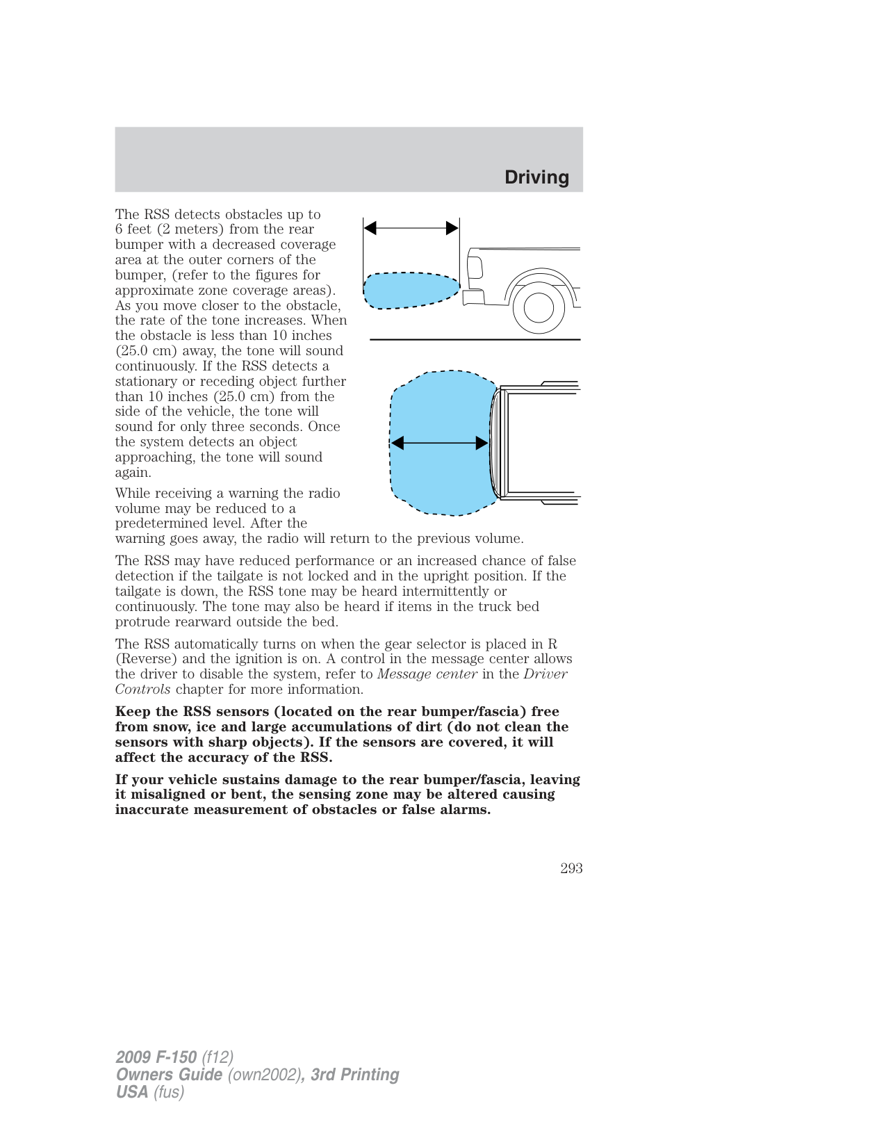
After shifting out of R (Reverse) and into any gear other than P (Park), the image in the navigation screen will remain until the vehicle speed reaches five mph (8 km/h), only if the rear camera delay feature is on, or until any navigation radio button is pressed.
Note: The default setting for the rear camera delay is off. Press the “Settings” button found on the navigation screen (if equipped) to set the rear camera delay feature to on or off.
When towing, the camera system will only see what is being towed behind the vehicle; this might not provide adequate coverage as it usually provides in normal operation and some objects might not be seen.
The camera lens for the camera system is located on the tailgate, under the Ford Oval. Keep the lens clean so the video image remains clear and undistorted. Clean the lens with a soft, lint-free cloth and non-abrasive cleaner.
Note: If the camera system image is not clear or seems distorted, it may be covered with water droplets, snow, mud or any other substance. If this occurs, clean the camera lens before using the camera system.
WARNING: The camera system is a reverse aid supplement device that still requires the driver to use it in conjunction with
the rearview mirror and the side mirrors for maximum coverage.
WARNING: Objects that are close to either corner of the bumper or under the bumper, might not be seen on the screen
due to the limited coverage of the camera system.
WARNING: Backup as slow as possible since higher speeds might limit your reaction time to stop the vehicle.
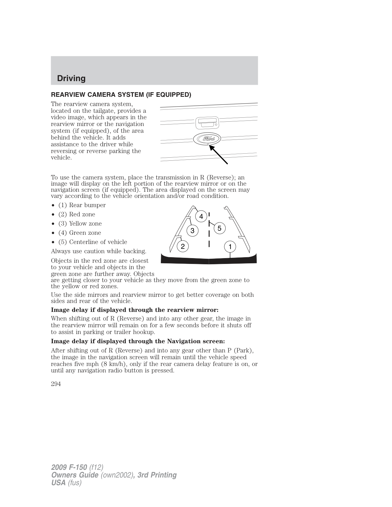
WARNING: Do not use the camera system with the tailgate open.
If the back end of the vehicle is hit or damaged, then check with your authorized dealer to have your rear video system checked for proper coverage and operation.
###### Night time and dark area use
###### Servicing
• If the image comes on while the vehicle is not in R (Reverse), have
the system inspected by your authorized dealer.
• If the image is not clear, then check if there is anything covering the lens such as dirt, mud, ice, snow, etc. If the image is still not clear after cleaning, have your system inspected by your authorized dealer.
###### FOUR-WHEEL DRIVE (4WD) OPERATION (IF EQUIPPED)
WARNING: For important information regarding safe operation of this type of vehicle, see Preparing to drive your vehicle in
this chapter.
Four–wheel drive (4WD) supplies power to all four wheels. 4WD should not be operated on dry pavement; driveline damage may occur.
If equipped with the Electronic Shift 4WD System, and 4X4 Low is selected while the vehicle is moving above 3 mph (5 km/h), the 4WD system will not perform a shift. This is normal and should be no reason for concern. Refer to Shifting to/from 4L (4X4 Low) for proper operation.
System indicator lights
Note: When a 4X4 system fault is present, the system will typically remain in whichever 4X4 mode was selected prior to the fault condition occurring. It will not default to 4X2 in all circumstances. When this warning is displayed, have your vehicle serviced by an authorized dealer.
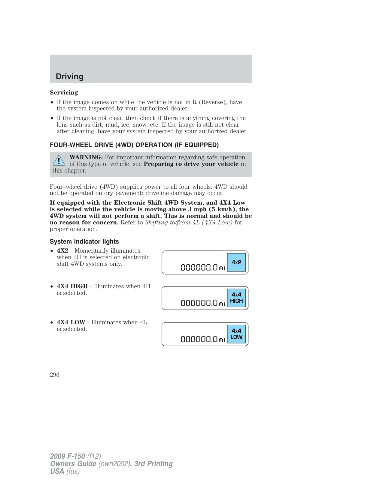
###### Using a manual 4WD system (if equipped)
• Move the transfer case lever between 2H (4X2) and 4H (4X4 High) at
a stop or any forward speed.
Note: Momentarily releasing the accelerator pedal while preforming a shift will improve engagement/disengagement times.
Note: Do not perform this operation if the rear wheels are slipping. Note: Some noise may be heard as the system shifts or engages; this is normal. Shifting to/from 4L (4X4 Low)
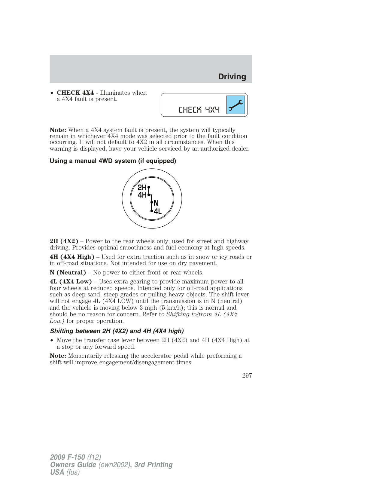
• If the transfer case will not engage into 4L (4X4 Low) do not force the lever. Allow the vehicle to coast at a speed below 3 mph (5 km/h), then repeat Steps 2 and 3.
Note: Some noise may be heard as the system shifts or engages; this is normal.
Note: For proper operation in 4X4 Low, ensure the transfer case shift lever is moved entirely rearward in to the 4L (4X4 Low) position and that the 4x4 Low light is displayed in the message center.
Note: Ideal 4L (4X4 Low) shift conditions occur when the vehicle is rolling at a speed below 3 mph (5 km/h) and the transmission is in N (Neutral).
Using the N (Neutral) position
The transfer case N (Neutral) position overrides the transmission and puts the vehicle in neutral regardless of transmission gearshift lever position. The vehicle can move forward or backward.
This position should only be used when towing the vehicle.
WARNING: Do not leave the vehicle unattended with the transfer case in the N (Neutral) position. Always set the parking
brake fully and turn off the ignition when leaving the vehicle.
###### Using the electronic shift 4WD system (if equipped)
4H (4X4 High) - Used for extra traction such as in snow or icy roads or in off-road situations. Not intended for use on dry pavement.
4L (4X4 Low) - Uses extra gearing to provide maximum power to all four wheels at reduced speeds. Intended only for off-road applications such as deep sand, steep grades or pulling heavy objects. 4L (4X4 Low) will not engage while the vehicle is moving above 3 mph (5 km/h); this is normal and should be no reason for concern. Refer to Shifting to/from 4L (4X4 Low) for proper operation.
###### Shifting between 2H (4X2 High) and 4H (4X4 High)
• Move the 4WD control between 2H (4X2 High) and 4H (4X4 High) at
any forward speed.
The message center will display 4X4 SHIFT IN PROGRESS during the system shift. “4X4 HIGH” will display in the message center.
Note: Momentarily releasing the accelerator pedal while preforming a shift will improve engagement/disengagement times.
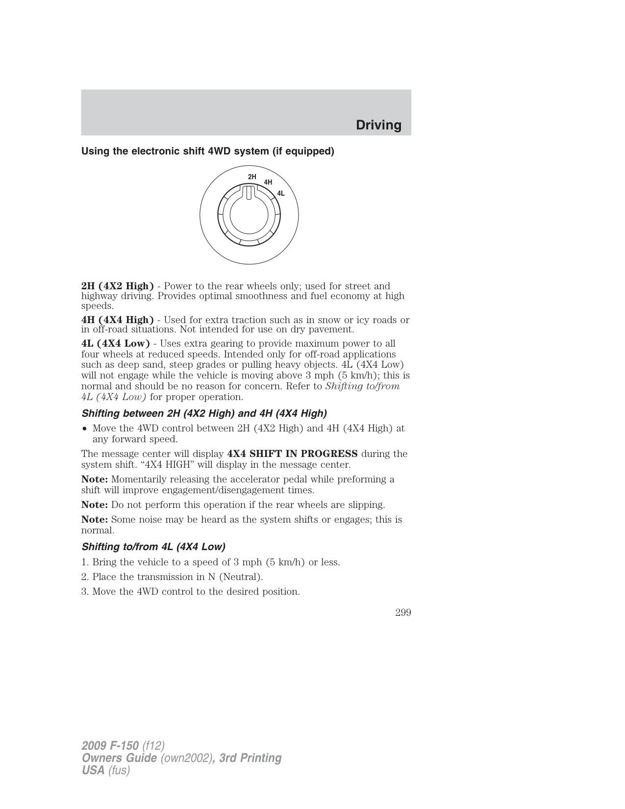
Note: Do not perform this operation if the rear wheels are slipping. Note: Some noise may be heard as the system shifts or engages; this is normal. Shifting to/from 4L (4X4 Low)
The message center will display 4X4 SHIFT IN PROGRESS during the shift. The message center will then display the system mode selected.
If any of the above shift conditions are not met, the shift will not occur and the message center will display information guiding the driver through the proper shifting procedures.
If 4X4 SHIFT IN PROGRESS is displayed for more than five seconds, transfer case gear tooth blockage is present. To alleviate this condition, move the vehicle forward approximately five feet
Note: Some noise may be heard as the system shifts or engages; this is normal.
###### Electronic locking differential (ELD) (if equipped)
The electronic locking differential (ELD) is a device housed in the rear axle which allows both rear wheels to turn at the same speed. The ELD can provide additional traction should the vehicle become stuck. The ELD is electronically activated by the driver and can be shifted on the fly. It is intended for use in mud, rocks, sand, or any off-road condition where maximum traction is needed. It is not intended for use on dry pavement.
The ELD is affected by the following conditions:
The ELD is designed for off-road use only.
###### Activating the electronic locking differential (ELD)
The ELD can be turned on by pulling the knob on the 4WD control toward you while the control is in either 4H (4X4 High) or 4L (4X4 Low) mode.
Once the knob is pulled, the light located on the control will blink for approximately two seconds and then it will remain solid.
Once the light on the control remains solid, both rear wheel axle shafts will be locked together providing added traction.
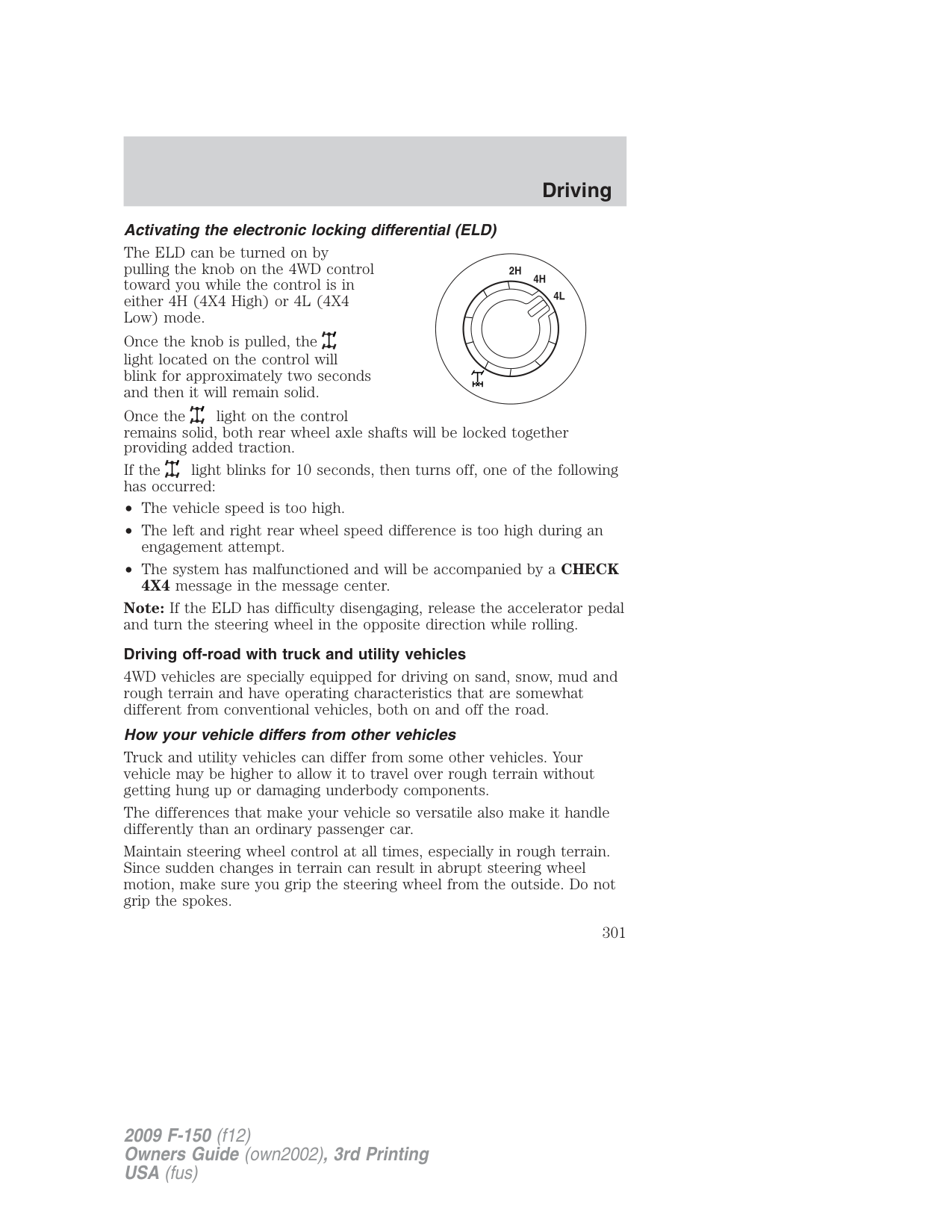
If the light blinks for 10 seconds, then turns off, one of the following has occurred:
Note: If the ELD has difficulty disengaging, release the accelerator pedal and turn the steering wheel in the opposite direction while rolling.
###### Driving off-road with truck and utility vehicles
4WD vehicles are specially equipped for driving on sand, snow, mud and rough terrain and have operating characteristics that are somewhat different from conventional vehicles, both on and off the road.
###### How your vehicle differs from other vehicles
Truck and utility vehicles can differ from some other vehicles. Your vehicle may be higher to allow it to travel over rough terrain without getting hung up or damaging underbody components.
The differences that make your vehicle so versatile also make it handle differently than an ordinary passenger car.
Maintain steering wheel control at all times, especially in rough terrain. Since sudden changes in terrain can result in abrupt steering wheel motion, make sure you grip the steering wheel from the outside. Do not grip the spokes.
Drive cautiously to avoid vehicle damage from concealed objects such as rocks and stumps.
You should either know the terrain or examine maps of the area before driving. Map out your route before driving in the area. To maintain steering and braking control of your vehicle, you must have all four wheels on the ground and they must be rolling, not sliding or spinning.
###### Basic operating principles
###### If your vehicle goes off the edge of the pavement
WARNING: Vehicles with a higher center of gravity such as utility and four-wheel drive vehicles handle differently than
vehicles with a lower center of gravity. Utility and four-wheel drive vehicles are not designed for cornering at speeds as high as passenger cars any more than low-slung sports cars are designed to perform satisfactorily under off-road conditions. Avoid sharp turns, excessive speed and abrupt maneuvers in these vehicles. Failure to drive cautiously could result in an increased risk of loss of vehicle control, vehicle rollover, personal injury and death.
###### If your vehicle gets stuck
If your vehicle gets stuck in mud or snow it may be rocked out by shifting between forward and reverse gears, stopping between shifts, in a steady pattern. Press lightly on the accelerator in each gear.
Do not rock the vehicle if the engine is not at normal operating temperature or damage to the transmission may occur.
Do not rock the vehicle for more than a few minutes or damage to the transmission and tires may occur or the engine may overheat.
WARNING: Do not spin the wheels at over 35 mph (56 km/h). The tires may fail and injure a passenger or bystander.
###### Emergency maneuvers
WARNING: Vehicles with a higher center of gravity such as utility and four-wheel drive vehicles handle differently than
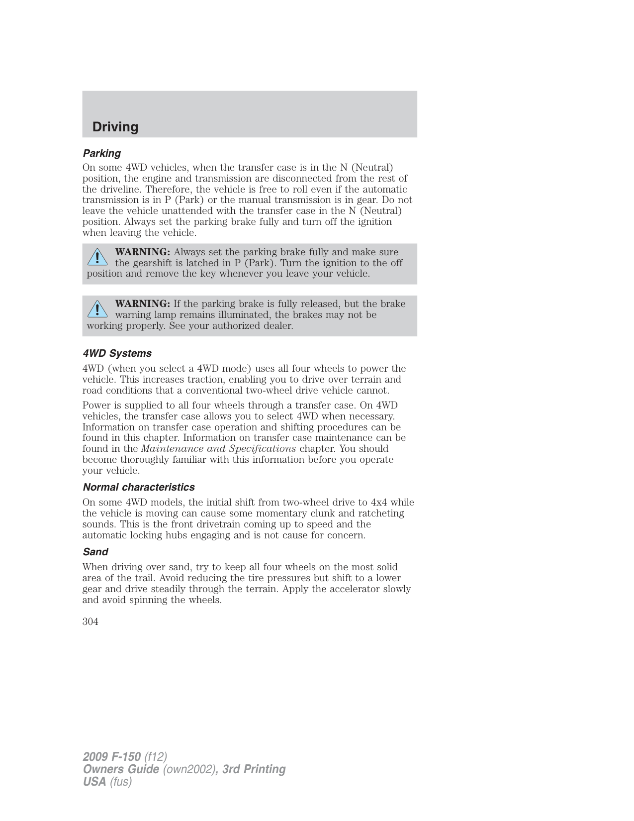
vehicles with a lower center of gravity. Utility and four-wheel drive vehicles are not designed for cornering at speeds as high as passenger cars any more than low-slung sports cars are designed to perform satisfactorily under off-road conditions. Avoid sharp turns, excessive speed and abrupt maneuvers in these vehicles. Failure to drive cautiously could result in an increased risk of loss of vehicle control, vehicle rollover, personal injury and death.
Parking On some 4WD vehicles, when the transfer case is in the N (Neutral) position, the engine and transmission are disconnected from the rest of the driveline. Therefore, the vehicle is free to roll even if the automatic transmission is in P (Park) or the manual transmission is in gear. Do not leave the vehicle unattended with the transfer case in the N (Neutral) position. Always set the parking brake fully and turn off the ignition when leaving the vehicle.
WARNING: Always set the parking brake fully and make sure the gearshift is latched in P (Park). Turn the ignition to the off
position and remove the key whenever you leave your vehicle.
WARNING: If the parking brake is fully released, but the brake warning lamp remains illuminated, the brakes may not be
working properly. See your authorized dealer.
###### 4WD Systems
4WD (when you select a 4WD mode) uses all four wheels to power the vehicle. This increases traction, enabling you to drive over terrain and road conditions that a conventional two-wheel drive vehicle cannot.
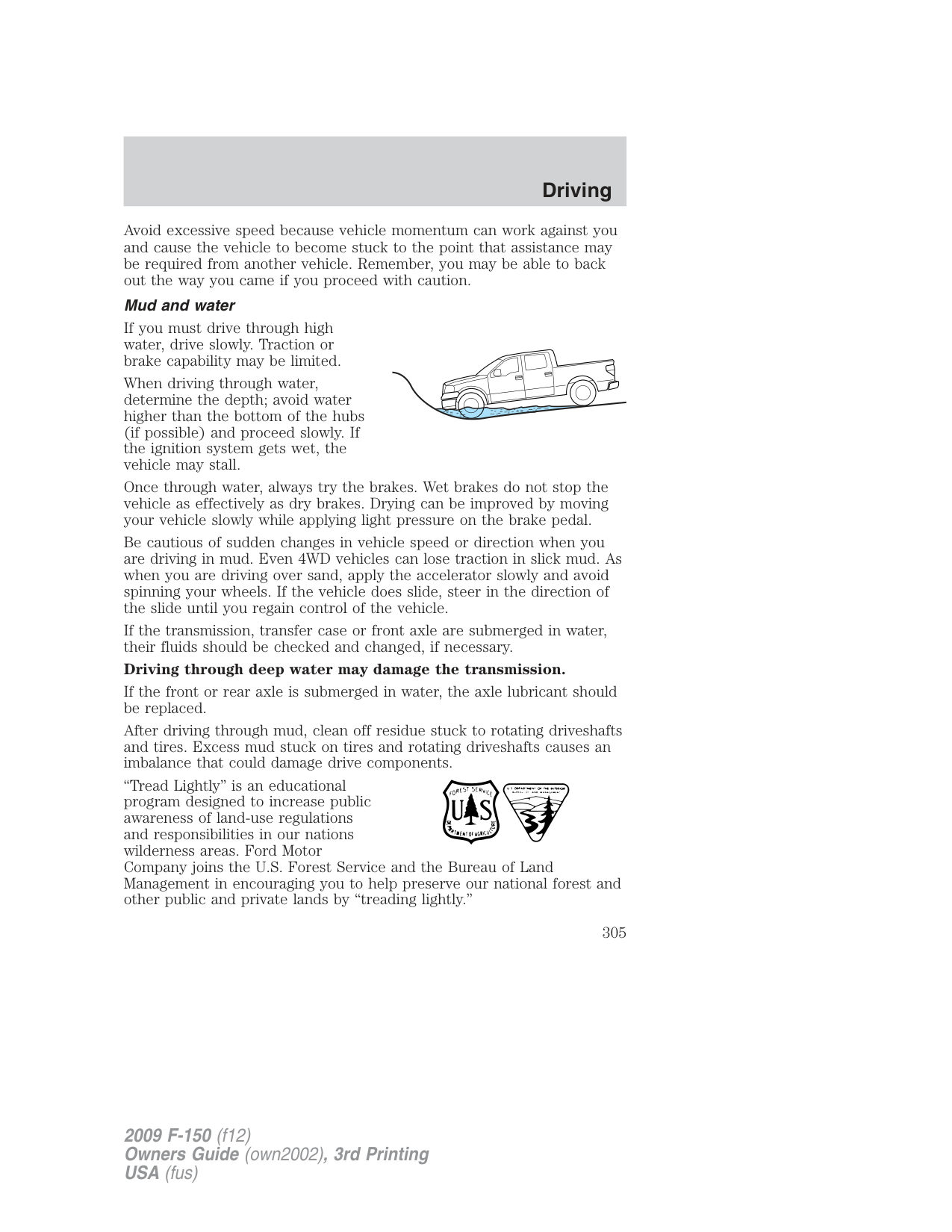
Power is supplied to all four wheels through a transfer case. On 4WD vehicles, the transfer case allows you to select 4WD when necessary. Information on transfer case operation and shifting procedures can be found in this chapter. Information on transfer case maintenance can be found in the Maintenance and Specifications chapter. You should become thoroughly familiar with this information before you operate your vehicle.
###### Normal characteristics
On some 4WD models, the initial shift from two-wheel drive to 4x4 while the vehicle is moving can cause some momentary clunk and ratcheting sounds. This is the front drivetrain coming up to speed and the automatic locking hubs engaging and is not cause for concern.
###### Sand
When driving over sand, try to keep all four wheels on the most solid area of the trail. Avoid reducing the tire pressures but shift to a lower gear and drive steadily through the terrain. Apply the accelerator slowly and avoid spinning the wheels.
Avoid excessive speed because vehicle momentum can work against you and cause the vehicle to become stuck to the point that assistance may be required from another vehicle. Remember, you may be able to back out the way you came if you proceed with caution.
###### Mud and water
If you must drive through high water, drive slowly. Traction or brake capability may be limited.
When driving through water, determine the depth; avoid water higher than the bottom of the hubs (if possible) and proceed slowly. If the ignition system gets wet, the vehicle may stall.
Once through water, always try the brakes. Wet brakes do not stop the vehicle as effectively as dry brakes. Drying can be improved by moving your vehicle slowly while applying light pressure on the brake pedal.
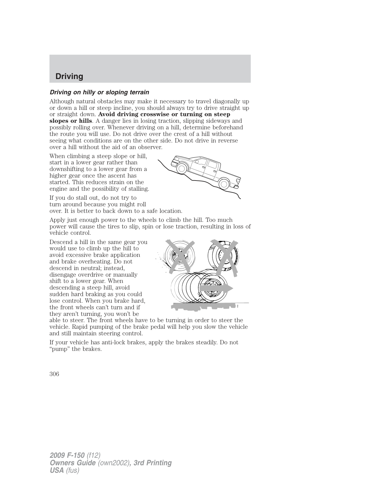
Be cautious of sudden changes in vehicle speed or direction when you are driving in mud. Even 4WD vehicles can lose traction in slick mud. As when you are driving over sand, apply the accelerator slowly and avoid spinning your wheels. If the vehicle does slide, steer in the direction of the slide until you regain control of the vehicle.
If the transmission, transfer case or front axle are submerged in water, their fluids should be checked and changed, if necessary.
###### Driving through deep water may damage the transmission.
If the front or rear axle is submerged in water, the axle lubricant should be replaced.
After driving through mud, clean off residue stuck to rotating driveshafts and tires. Excess mud stuck on tires and rotating driveshafts causes an imbalance that could damage drive components.
“Tread Lightly” is an educational program designed to increase public awareness of land-use regulations and responsibilities in our nations wilderness areas. Ford Motor Company joins the U.S. Forest Service and the Bureau of Land Management in encouraging you to help preserve our national forest and other public and private lands by “treading lightly.”
###### Driving on hilly or sloping terrain
Although natural obstacles may make it necessary to travel diagonally up or down a hill or steep incline, you should always try to drive straight up or straight down. Avoid driving crosswise or turning on steep
slopes or hills. A danger lies in losing traction, slipping sideways and possibly rolling over. Whenever driving on a hill, determine beforehand the route you will use. Do not drive over the crest of a hill without seeing what conditions are on the other side. Do not drive in reverse over a hill without the aid of an observer.
When climbing a steep slope or hill, start in a lower gear rather than downshifting to a lower gear from a higher gear once the ascent has started. This reduces strain on the engine and the possibility of stalling.
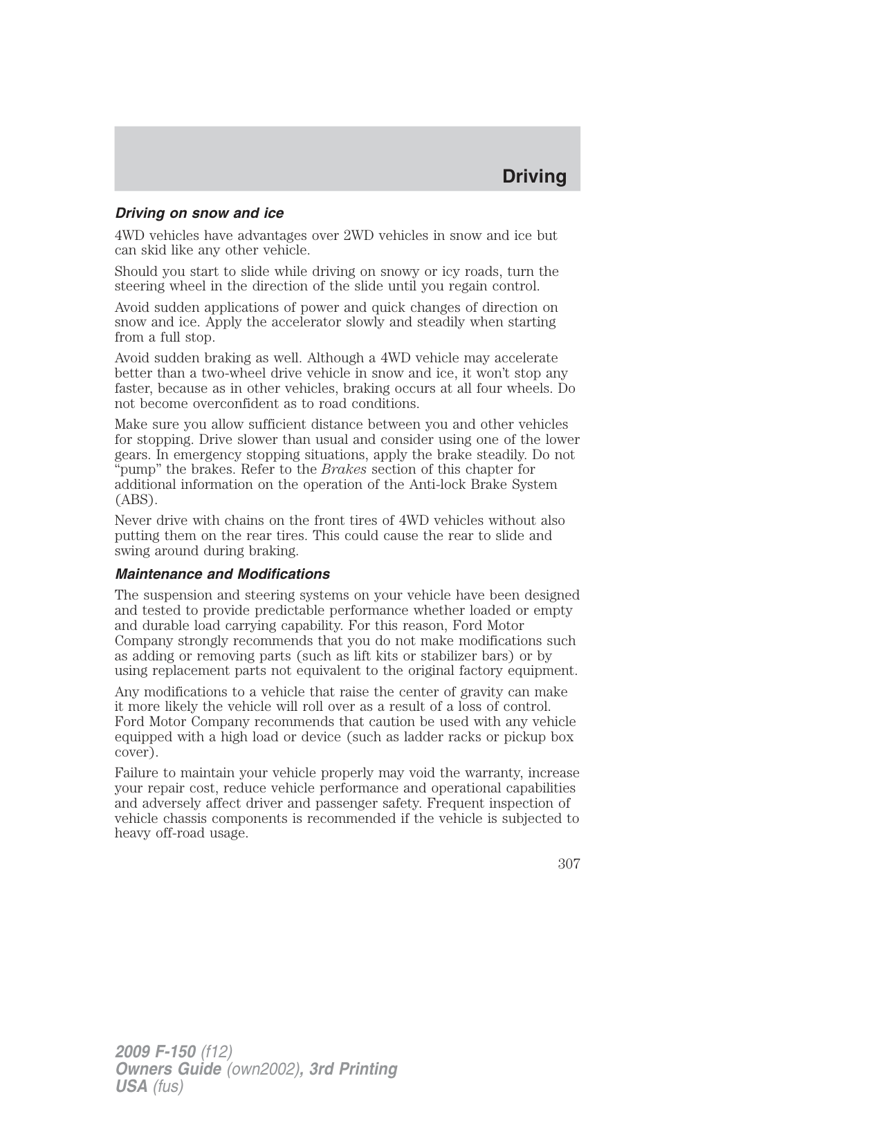
If you do stall out, do not try to turn around because you might roll over. It is better to back down to a safe location.
Apply just enough power to the wheels to climb the hill. Too much power will cause the tires to slip, spin or lose traction, resulting in loss of vehicle control.
Descend a hill in the same gear you would use to climb up the hill to avoid excessive brake application and brake overheating. Do not descend in neutral; instead, disengage overdrive or manually shift to a lower gear. When descending a steep hill, avoid sudden hard braking as you could lose control. When you brake hard, the front wheels can’t turn and if they aren’t turning, you won’t be able to steer. The front wheels have to be turning in order to steer the vehicle. Rapid pumping of the brake pedal will help you slow the vehicle and still maintain steering control.
If your vehicle has anti-lock brakes, apply the brakes steadily. Do not “pump” the brakes.
###### Driving on snow and ice
4WD vehicles have advantages over 2WD vehicles in snow and ice but can skid like any other vehicle.
Should you start to slide while driving on snowy or icy roads, turn the steering wheel in the direction of the slide until you regain control.
Avoid sudden applications of power and quick changes of direction on snow and ice. Apply the accelerator slowly and steadily when starting from a full stop.
Avoid sudden braking as well. Although a 4WD vehicle may accelerate better than a two-wheel drive vehicle in snow and ice, it won’t stop any faster, because as in other vehicles, braking occurs at all four wheels. Do not become overconfident as to road conditions.
Make sure you allow sufficient distance between you and other vehicles for stopping. Drive slower than usual and consider using one of the lower gears. In emergency stopping situations, apply the brake steadily. Do not “pump” the brakes. Refer to the Brakes section of this chapter for additional information on the operation of the Anti-lock Brake System (ABS).
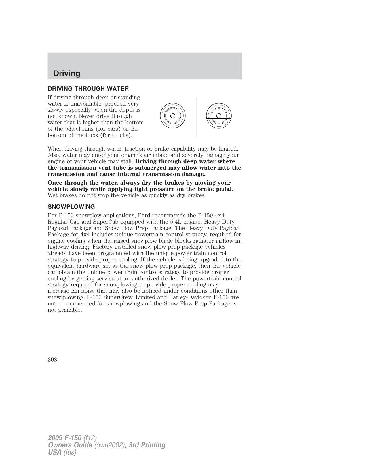
Never drive with chains on the front tires of 4WD vehicles without also putting them on the rear tires. This could cause the rear to slide and swing around during braking.
###### Maintenance and Modifications
The suspension and steering systems on your vehicle have been designed and tested to provide predictable performance whether loaded or empty and durable load carrying capability. For this reason, Ford Motor Company strongly recommends that you do not make modifications such as adding or removing parts (such as lift kits or stabilizer bars) or by using replacement parts not equivalent to the original factory equipment.
Any modifications to a vehicle that raise the center of gravity can make it more likely the vehicle will roll over as a result of a loss of control. Ford Motor Company recommends that caution be used with any vehicle equipped with a high load or device (such as ladder racks or pickup box cover).
Failure to maintain your vehicle properly may void the warranty, increase your repair cost, reduce vehicle performance and operational capabilities and adversely affect driver and passenger safety. Frequent inspection of vehicle chassis components is recommended if the vehicle is subjected to heavy off-road usage.
###### DRIVING THROUGH WATER
If driving through deep or standing water is unavoidable, proceed very slowly especially when the depth is not known. Never drive through water that is higher than the bottom of the wheel rims (for cars) or the bottom of the hubs (for trucks).
When driving through water, traction or brake capability may be limited. Also, water may enter your engine’s air intake and severely damage your engine or your vehicle may stall. Driving through deep water where
the transmission vent tube is submerged may allow water into the transmission and cause internal transmission damage.
Once through the water, always dry the brakes by moving your vehicle slowly while applying light pressure on the brake pedal. Wet brakes do not stop the vehicle as quickly as dry brakes.
SNOWPLOWING
For F-150 snowplow applications, Ford recommends the F-150 4x4 Regular Cab and SuperCab equipped with the 5.4L engine, Heavy Duty Payload Package and Snow Plow Prep Package. The Heavy Duty Payload Package for 4x4 includes unique powertrain control strategy, required for engine cooling when the raised snowplow blade blocks radiator airflow in highway driving. Factory installed snow plow prep package vehicles already have been programmed with the unique power train control strategy to provide proper cooling. If the vehicle is being upgraded to the equivalent hardware set as the snow plow prep package, then the vehicle can obtain the unique power train control strategy to provide proper cooling by getting service at an authorized dealer. The powertrain control strategy required for snowplowing to provide proper cooling may increase fan noise that may also be noticed under conditions other than snow plowing. F-150 SuperCrew, Limited and Harley-Davidson F-150 are not recommended for snowplowing and the Snow Plow Prep Package is not available.
###### Installing the snowplow
Weight limits and guidelines for selecting and installing the snowplow can be found in the Ford Truck Body Builders Layout Book, Snowplow section, found at www.fleet.ford.com/truckbbas. A typical installation affects the following:
###### Operating the vehicle with the snowplow attached
Ford recommends that the F–150 be limited to low speed, personal-use snow removal. Do not use your vehicle for snow removal until it has been driven at least 500 miles (800 km).
The attached snowplow blade restricts airflow to the radiator, and may cause the engine to run at a higher temperature. Attention to engine temperature is especially important when outside temperatures are above freezing. Angle the blade to maximize airflow to the radiator and monitor engine temperature to determine whether a left or right angle provides the best performance.
###### Snowplowing with your airbag equipped vehicle
Your vehicle is equipped with a driver and passenger air bag Supplemental Restraint System (SRS) The SRS is designed to activate in certain frontal and offset frontal collisions when the vehicle sustains sufficient longitudinal deceleration.
Careless or high speed driving while plowing snow which results in sufficient vehicle decelerations can deploy the airbag. Such driving also increases the risk of accidents.
WARNING: All occupants of the vehicle, including the driver, should always properly wear their safety belts, even when an air
bag supplemental restraint system (SRS) is provided.
Never remove or defeat the “tripping mechanisms” designed into the snow removal equipment by its manufacturer. Doing so may cause damage to the vehicle and the snow removal equipment as well as possible air bag deployment.
WARNING: Do not attempt to service, repair, or modify the air bag supplemental restraint system (SRS) or its fuses. See your
Ford or Lincoln Mercury dealer.
###### Transmission operation while plowing
Do not rock the vehicle if the engine is not at operating temperature. Do not rock the vehicle for more than a minute. The transmission and tires may be damaged or the engine may overheat.
WARNING: Do not spin the wheels at over 35 mph (55 km/h). The tires may fail and injure a passenger or bystander.
###### Engine temperature while plowing
When driving with a plow, your engine may run at a higher temperature than normal because the attached snowplow blade will restrict airflow to the radiator.
If you are driving more than 15 miles (24 km) at temperatures above freezing, angle the plow blade either full left or full right to provide maximum airflow to the radiator.
If you are driving less than 15 miles (24 km) at speeds up to 40 mph (64 km/h) in cold weather, you will not need to worry about blade position to provide maximum airflow.
Factory installed snow plow prep package vehicles already have been programmed with the unique power train control strategy to provide proper cooling. If the vehicle is being upgraded to the equivalent hardware set as the snow plow prep package, then the vehicle can obtain the unique power train control strategy to provide proper cooling by getting service at an authorized dealer. The powertrain control strategy required for snowplowing to provide proper cooling may increase fan noise that may also be noticed under conditions other than snow plowing.
ROADSIDE ASSISTANCE Getting roadside assistance
To fully assist you should you have a vehicle concern, Ford Motor Company offers a complimentary roadside assistance program. This program is separate from the New Vehicle Limited Warranty. The service is available:
Roadside assistance will cover:
Trailers shall be covered up to $200 if the disabled eligible vehicle requires service at the nearest authorized dealer. If the trailer is disabled, but the towing vehicle is operational, the trailer does not qualify for any roadside services.
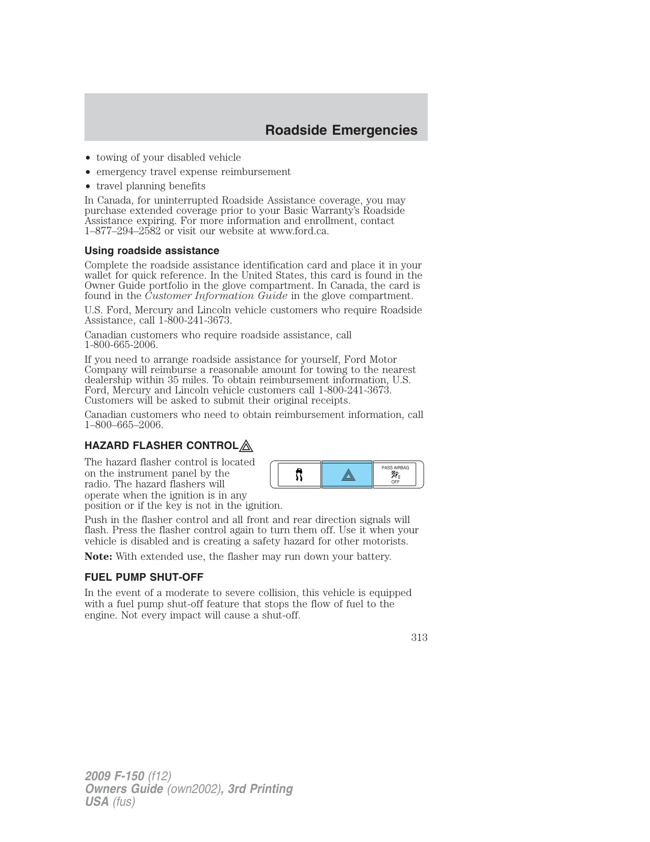
Canadian customers refer to your Customer Information Guide for information on:
In Canada, for uninterrupted Roadside Assistance coverage, you may purchase extended coverage prior to your Basic Warranty’s Roadside Assistance expiring. For more information and enrollment, contact 1–877–294–2582 or visit our website at www.ford.ca.
###### Using roadside assistance
Complete the roadside assistance identification card and place it in your wallet for quick reference. In the United States, this card is found in the Owner Guide portfolio in the glove compartment. In Canada, the card is found in the Customer Information Guide in the glove compartment.
U.S. Ford, Mercury and Lincoln vehicle customers who require Roadside Assistance, call 1-800-241-3673.
Canadian customers who require roadside assistance, call 1-800-665-2006.
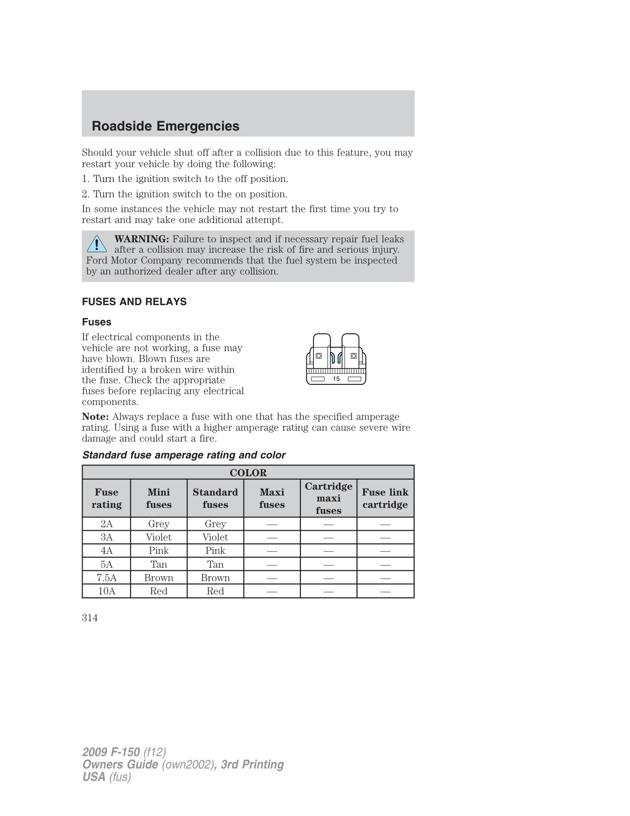
If you need to arrange roadside assistance for yourself, Ford Motor Company will reimburse a reasonable amount for towing to the nearest dealership within 35 miles. To obtain reimbursement information, U.S. Ford, Mercury and Lincoln vehicle customers call 1-800-241-3673. Customers will be asked to submit their original receipts.
Canadian customers who need to obtain reimbursement information, call 1–800–665–2006.
HAZARD FLASHER CONTROL The hazard flasher control is located on the instrument panel by the radio. The hazard flashers will operate when the ignition is in any position or if the key is not in the ignition. Push in the flasher control and all front and rear direction signals will flash. Press the flasher control again to turn them off. Use it when your vehicle is disabled and is creating a safety hazard for other motorists. Note: With extended use, the flasher may run down your battery. FUEL PUMP SHUT-OFF
| | |---| | |
In the event of a moderate to severe collision, this vehicle is equipped with a fuel pump shut-off feature that stops the flow of fuel to the engine. Not every impact will cause a shut-off.
Should your vehicle shut off after a collision due to this feature, you may restart your vehicle by doing the following:
WARNING: Failure to inspect and if necessary repair fuel leaks after a collision may increase the risk of fire and serious injury.
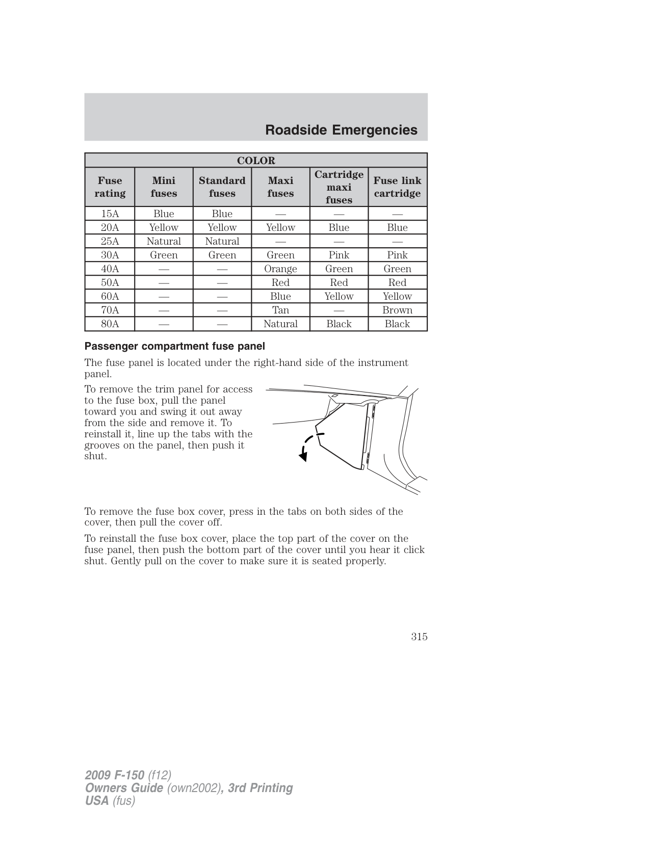
Ford Motor Company recommends that the fuel system be inspected by an authorized dealer after any collision.
FUSES AND RELAYS Fuses
If electrical components in the vehicle are not working, a fuse may have blown. Blown fuses are identified by a broken wire within the fuse. Check the appropriate fuses before replacing any electrical components.
| | | | | | | | | | | | | | | | | | |---|---|---|---|---|---|---|---|---|---|---|---|---|---|---|---|---| | | | | | | | | | | | | | | | | | | | | | | | | | | | | | | | | | | | | | | | | | | | | | | | | | | | | | | | | | | | | | | | | | | | | | | | |
15
Note: Always replace a fuse with one that has the specified amperage rating. Using a fuse with a higher amperage rating can cause severe wire damage and could start a fire.
Standard fuse amperage rating and color
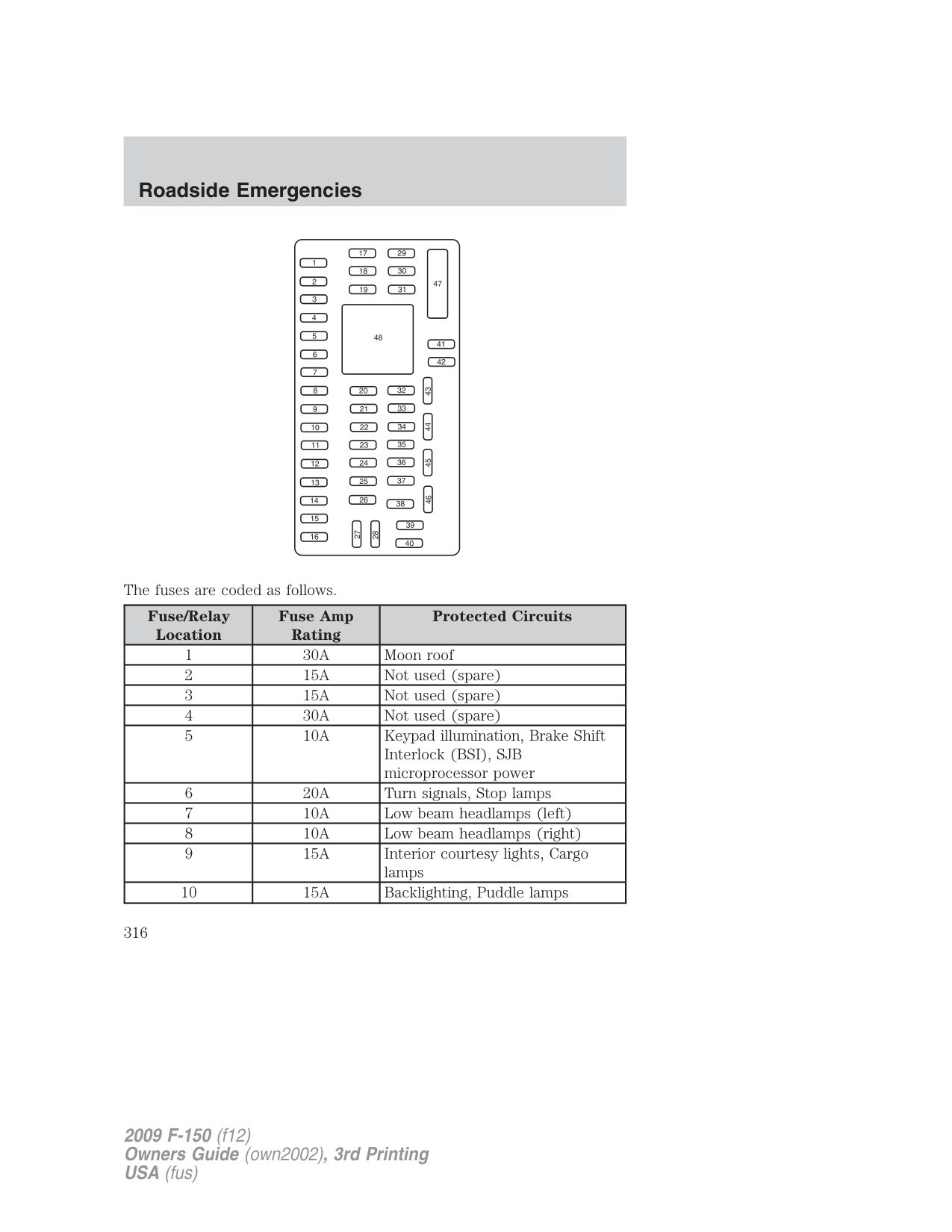
|COLOR|COLOR|COLOR|COLOR|COLOR|COLOR| |---|---|---|---|---|---| |Fuse rating|Mini fuses|Standard fuses|Maxi fuses|Cartridge maxi fuses|Fuse link cartridge| |2A|Grey|Grey|—|—|—| |3A|Violet|Violet|—|—|—| |4A|Pink|Pink|—|—|—| |5A|Tan|Tan|—|—|—| |7.5A|Brown|Brown|—|—|—| |10A|Red|Red|—|—|—|
|COLOR|COLOR|COLOR|COLOR|COLOR|COLOR| |---|---|---|---|---|---| |Fuse rating|Mini fuses|Standard fuses|Maxi fuses|Cartridge maxi fuses|Fuse link cartridge| |15A|Blue|Blue|—|—|—| |20A|Yellow|Yellow|Yellow|Blue|Blue| |25A|Natural|Natural|—|—|—| |30A|Green|Green|Green|Pink|Pink| |40A|—|—|Orange|Green|Green| |50A|—|—|Red|Red|Red|
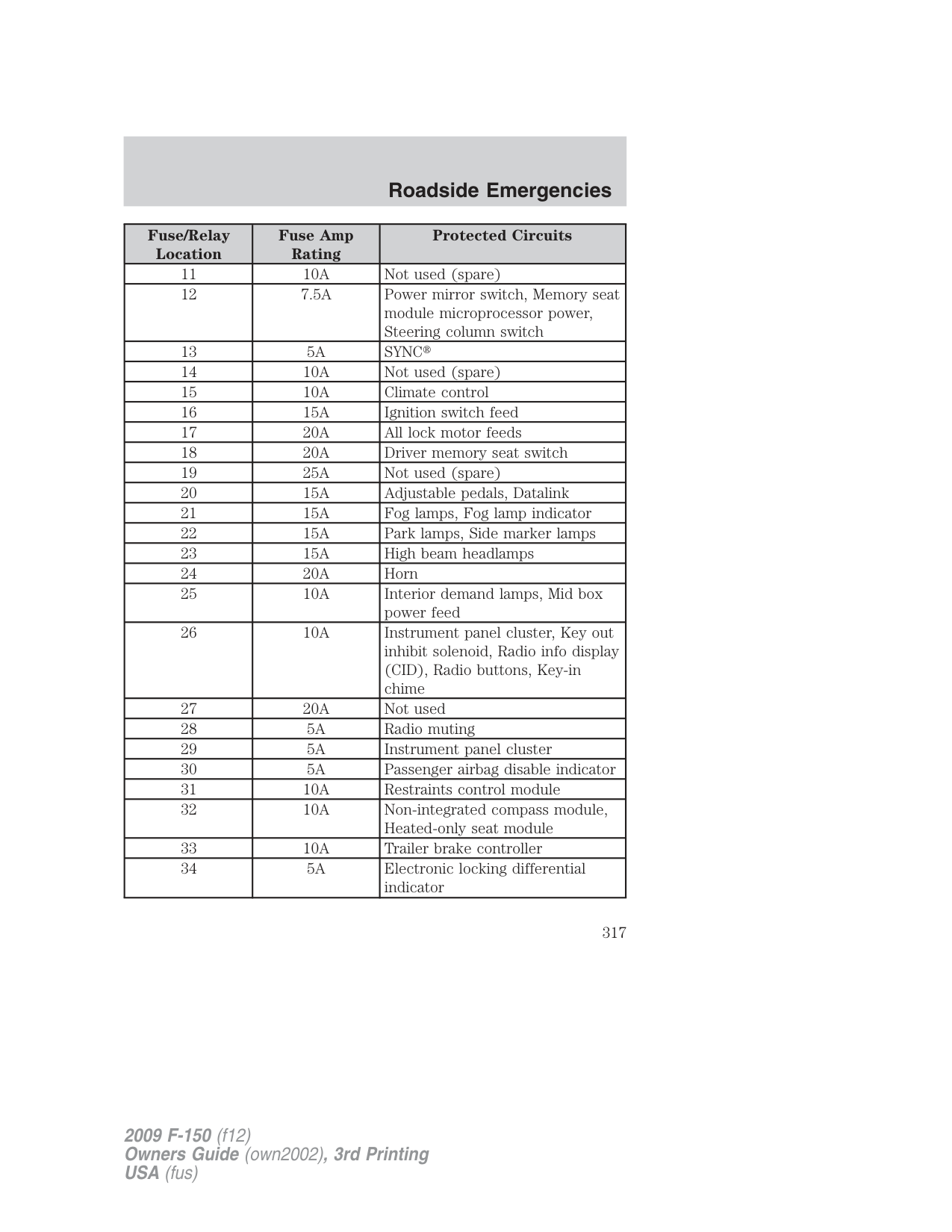
|60A|—|—|Blue|Yellow|Yellow| |70A|—|—|Tan|—|Brown| |80A|—|—|Natural|Black|Black|
###### Passenger compartment fuse panel
The fuse panel is located under the right-hand side of the instrument panel.
To remove the trim panel for access to the fuse box, pull the panel toward you and swing it out away from the side and remove it. To reinstall it, line up the tabs with the grooves on the panel, then push it shut.
To remove the fuse box cover, press in the tabs on both sides of the cover, then pull the cover off.
To reinstall the fuse box cover, place the top part of the cover on the fuse panel, then push the bottom part of the cover until you hear it click shut. Gently pull on the cover to make sure it is seated properly.
####### The fuses are coded as follows.
|Fuse/Relay Location|Fuse Amp Rating|Protected Circuits| |---|---|---| |1|30A|Moon roof|
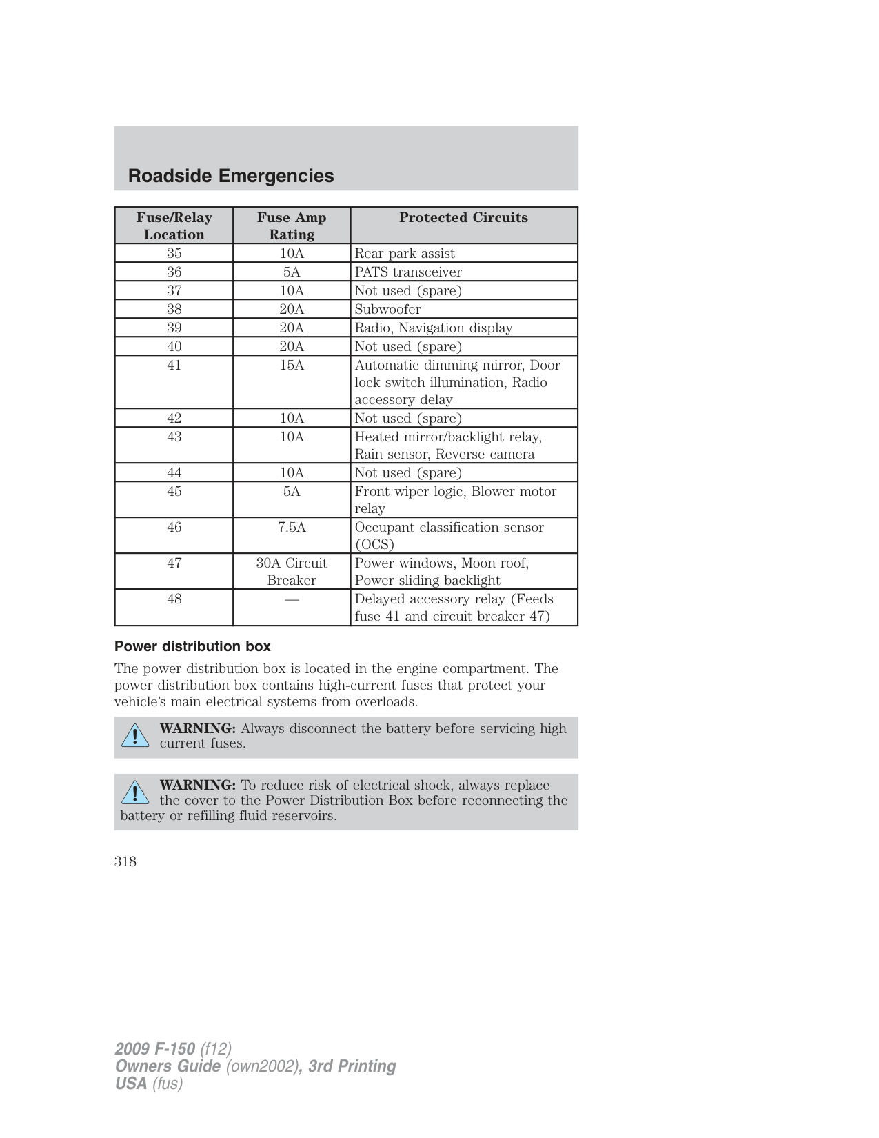
|2|15A|Not used (spare)| |3|15A|Not used (spare)| |4|30A|Not used (spare)| |5|10A|Keypad illumination, Brake Shift Interlock (BSI), SJB microprocessor power| |6|20A|Turn signals, Stop lamps| |7|10A|Low beam headlamps (left)| |8|10A|Low beam headlamps (right)| |9|15A|Interior courtesy lights, Cargo lamps| |10|15A|Backlighting, Puddle lamps|
|Fuse/Relay Location|Fuse Amp Rating|Protected Circuits| |---|---|---| |11|10A|Not used (spare)| |12|7.5A|Power mirror switch, Memory seat module microprocessor power, Steering column switch| |13|5A|SYNC| |14|10A|Not used (spare)| |15|10A|Climate control| |16|15A|Ignition switch feed| |17|20A|All lock motor feeds|
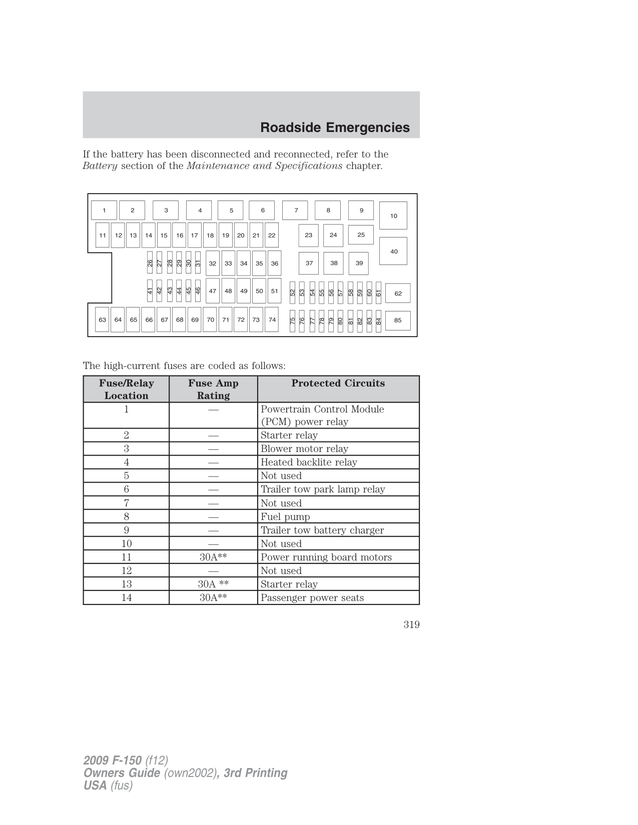
|18|20A|Driver memory seat switch| |19|25A|Not used (spare)| |20|15A|Adjustable pedals, Datalink| |21|15A|Fog lamps, Fog lamp indicator| |22|15A|Park lamps, Side marker lamps| |23|15A|High beam headlamps| |24|20A|Horn| |25|10A|Interior demand lamps, Mid box power feed| |26|10A|Instrument panel cluster, Key out inhibit solenoid, Radio info display (CID), Radio buttons, Key-in chime| |27|20A|Not used| |28|5A|Radio muting| |29|5A|Instrument panel cluster| |30|5A|Passenger airbag disable indicator| |31|10A|Restraints control module| |32|10A|Non-integrated compass module, Heated-only seat module| |33|10A|Trailer brake controller| |34|5A|Electronic locking differential indicator|
|Fuse/Relay Location|Fuse Amp Rating|Protected Circuits|
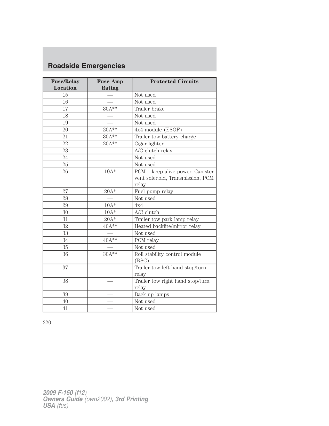
|---|---|---| |35|10A|Rear park assist| |36|5A|PATS transceiver| |37|10A|Not used (spare)| |38|20A|Subwoofer| |39|20A|Radio, Navigation display| |40|20A|Not used (spare)| |41|15A|Automatic dimming mirror, Door lock switch illumination, Radio accessory delay| |42|10A|Not used (spare)| |43|10A|Heated mirror/backlight relay, Rain sensor, Reverse camera| |44|10A|Not used (spare)| |45|5A|Front wiper logic, Blower motor relay| |46|7.5A|Occupant classification sensor (OCS)| |47|30A Circuit Breaker|Power windows, Moon roof, Power sliding backlight| |48|—|Delayed accessory relay (Feeds fuse 41 and circuit breaker 47)|
###### Power distribution box
The power distribution box is located in the engine compartment. The power distribution box contains high-current fuses that protect your vehicle’s main electrical systems from overloads.
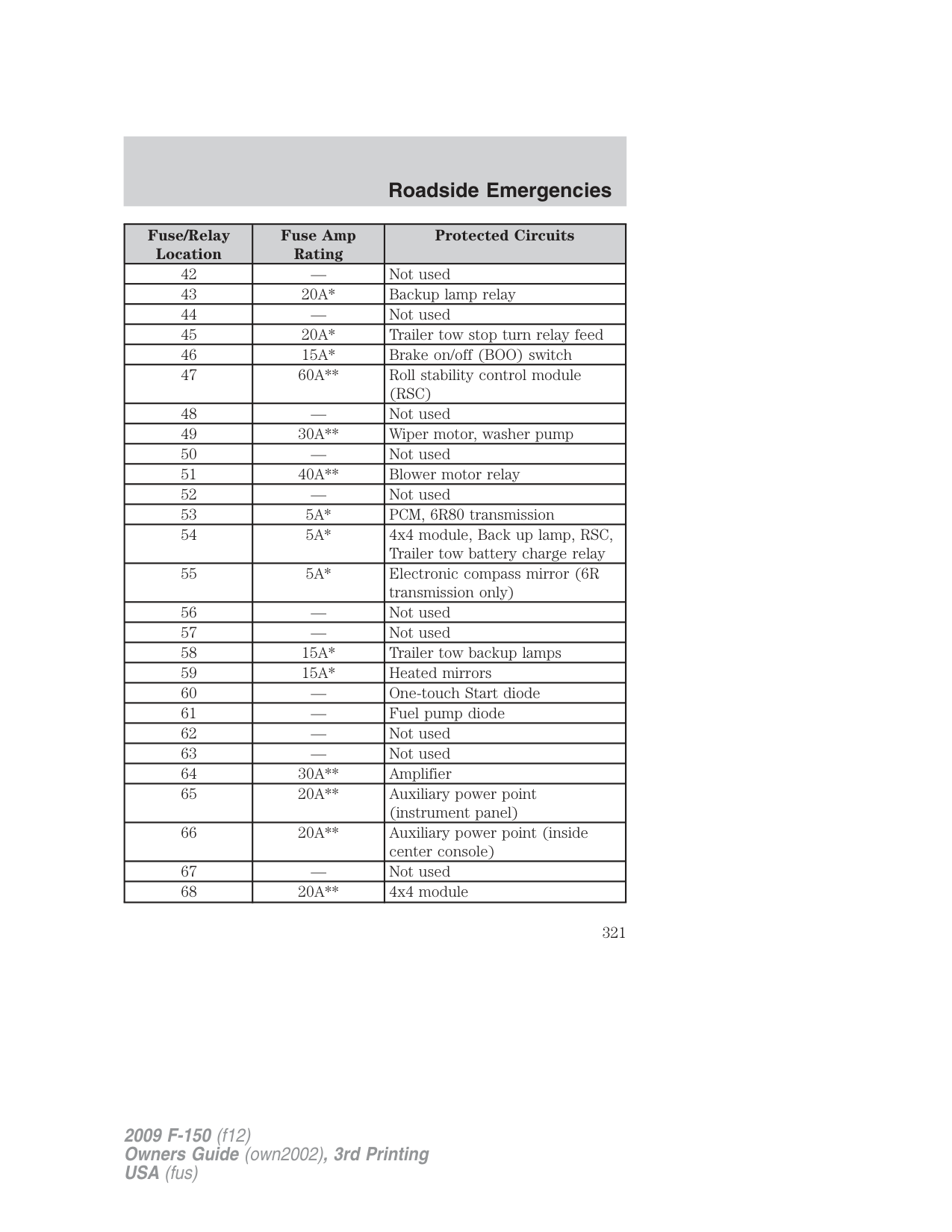
WARNING: Always disconnect the battery before servicing high current fuses.
WARNING: To reduce risk of electrical shock, always replace the cover to the Power Distribution Box before reconnecting the
battery or refilling fluid reservoirs.
If the battery has been disconnected and reconnected, refer to the Battery section of the Maintenance and Specifications chapter.
The high-current fuses are coded as follows:
|Fuse/Relay Location|Fuse Amp Rating|Protected Circuits| |---|---|---| |1|—|Powertrain Control Module (PCM) power relay| |2|—|Starter relay| |3|—|Blower motor relay| |4|—|Heated backlite relay| |5|—|Not used| |6|—|Trailer tow park lamp relay| |7|—|Not used|
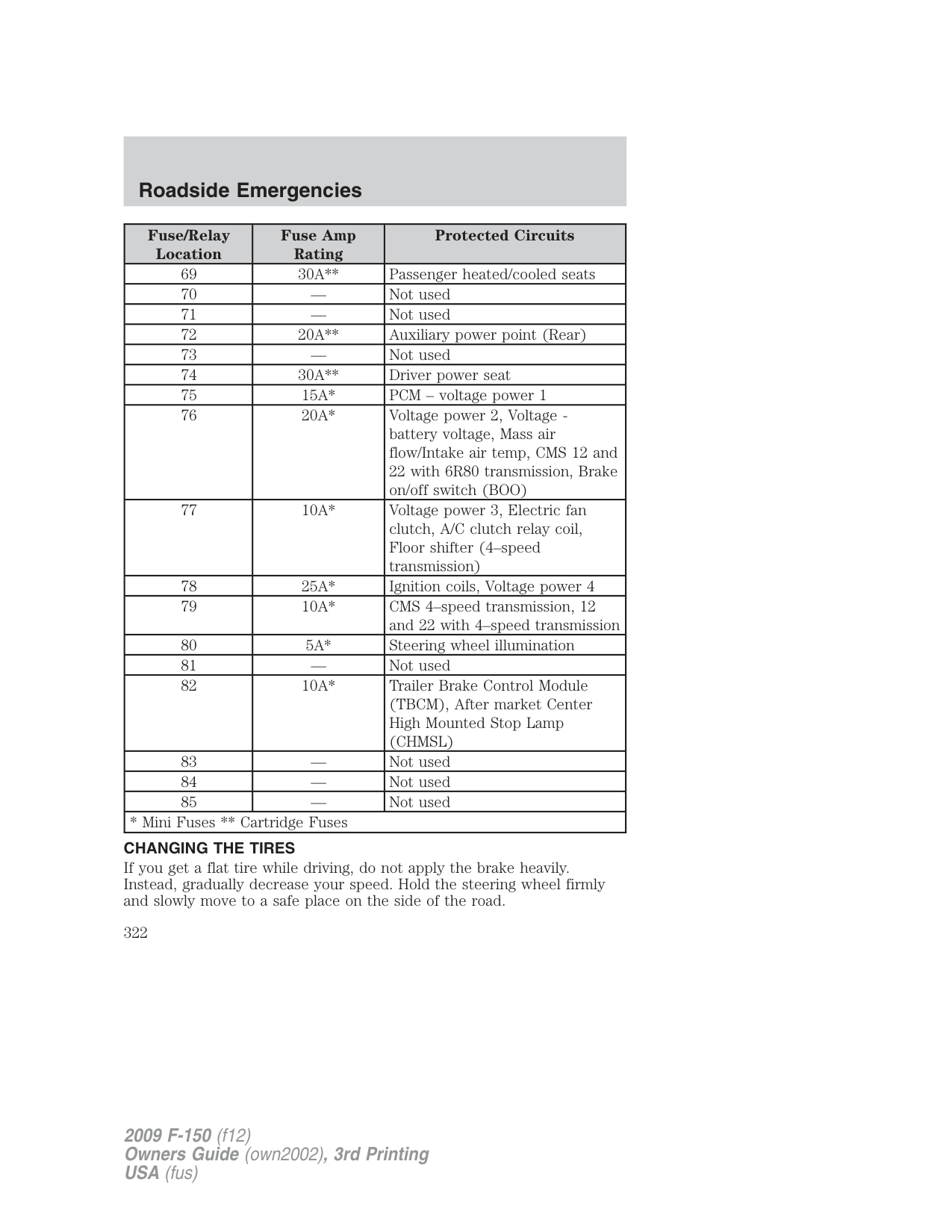
|8|—|Fuel pump| |9|—|Trailer tow battery charger| |10|—|Not used| |11|30A**|Power running board motors| |12|—|Not used| |13|30A **|Starter relay| |14|30A**|Passenger power seats|
|Fuse/Relay Location|Fuse Amp Rating|Protected Circuits| |---|---|---| |15|—|Not used| |16|—|Not used| |17|30A**|Trailer brake| |18|—|Not used| |19|—|Not used| |20|20A**|4x4 module (ESOF)| |21|30A**|Trailer tow battery charge| |22|20A**|Cigar lighter| |23|—|A/C clutch relay|
|24|—|Not used| |25|—|Not used| |26|10A*|PCM – keep alive power, Canister vent solenoid, Transmission, PCM relay| |27|20A*|Fuel pump relay| |28|—|Not used| |29|10A*|4x4| |30|10A*|A/C clutch| |31|20A*|Trailer tow park lamp relay| |32|40A**|Heated backlite/mirror relay| |33|—|Not used| |34|40A**|PCM relay| |35|—|Not used| |36|30A**|Roll stability control module (RSC)| |37|—|Trailer tow left hand stop/turn relay| |38|—|Trailer tow right hand stop/turn relay| |39|—|Back up lamps| |40|—|Not used| |41|—|Not used|
|Fuse/Relay Location|Fuse Amp Rating|Protected Circuits| |---|---|---| |42|—|Not used| |43|20A*|Backup lamp relay| |44|—|Not used| |45|20A*|Trailer tow stop turn relay feed| |46|15A*|Brake on/off (BOO) switch| |47|60A**|Roll stability control module (RSC)| |48|—|Not used| |49|30A**|Wiper motor, washer pump| |50|—|Not used| |51|40A**|Blower motor relay| |52|—|Not used| |53|5A*|PCM, 6R80 transmission| |54|5A*|4x4 module, Back up lamp, RSC, Trailer tow battery charge relay| |55|5A*|Electronic compass mirror (6R transmission only)| |56|—|Not used| |57|—|Not used| |58|15A*|Trailer tow backup lamps| |59|15A*|Heated mirrors|
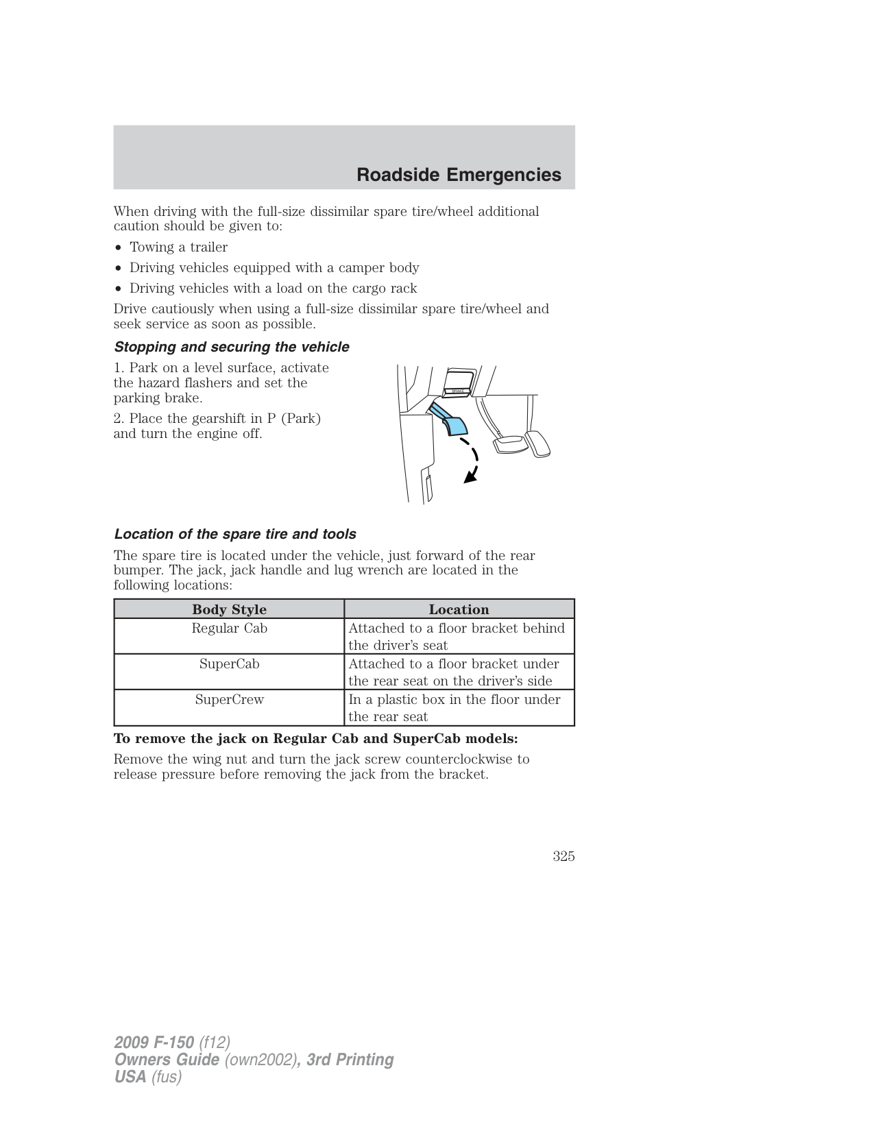
|60|—|One-touch Start diode| |61|—|Fuel pump diode| |62|—|Not used| |63|—|Not used| |64|30A**|Amplifier| |65|20A**|Auxiliary power point (instrument panel)| |66|20A**|Auxiliary power point (inside center console)| |67|—|Not used| |68|20A**|4x4 module|
|Fuse/Relay Location|Fuse Amp Rating|Protected Circuits| |---|---|---| |69|30A**|Passenger heated/cooled seats| |70|—|Not used| |71|—|Not used| |72|20A**|Auxiliary power point (Rear)| |73|—|Not used| |74|30A**|Driver power seat| |75|15A*|PCM – voltage power 1|
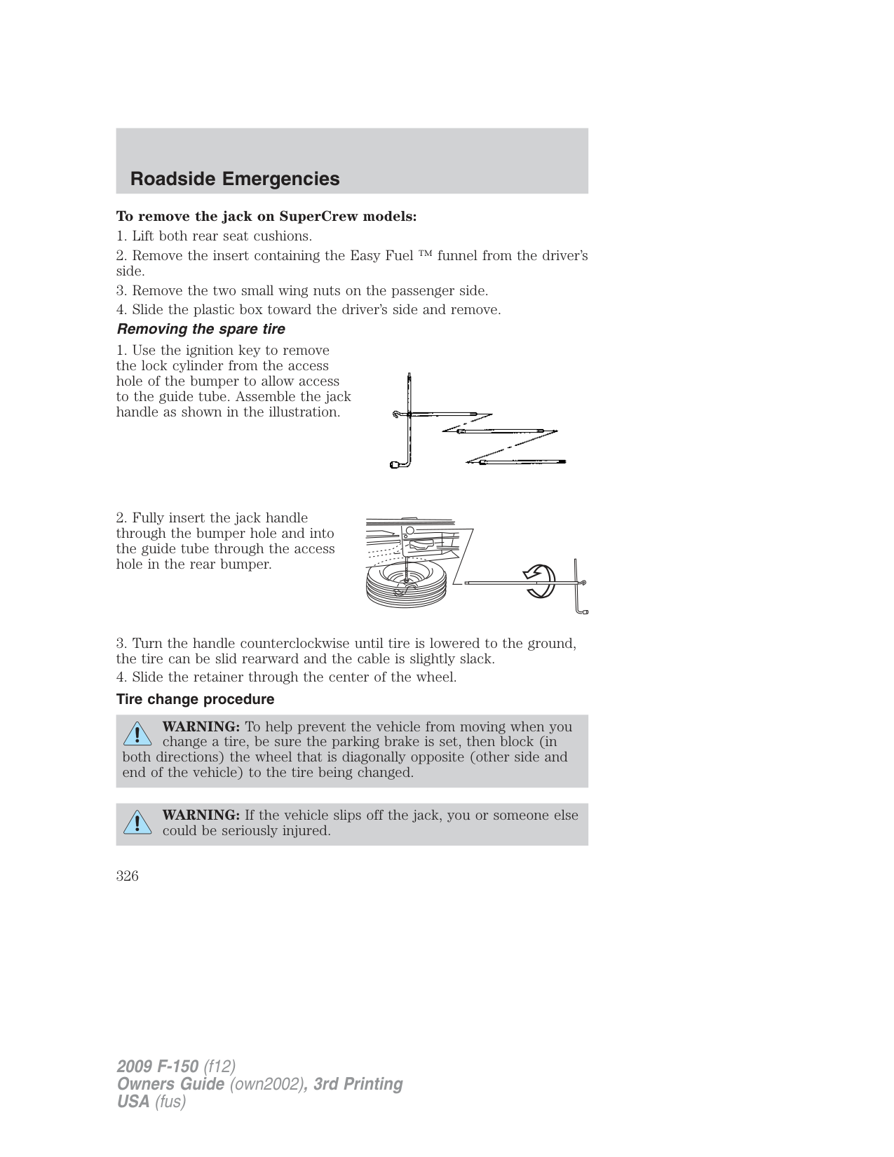
|76|20A*|Voltage power 2, Voltage battery voltage, Mass air flow/Intake air temp, CMS 12 and 22 with 6R80 transmission, Brake on/off switch (BOO)| |77|10A*|Voltage power 3, Electric fan clutch, A/C clutch relay coil, Floor shifter (4–speed transmission)| |78|25A*|Ignition coils, Voltage power 4| |79|10A*|CMS 4–speed transmission, 12 and 22 with 4–speed transmission| |80|5A*|Steering wheel illumination| |81|—|Not used| |82|10A*|Trailer Brake Control Module (TBCM), After market Center High Mounted Stop Lamp (CHMSL)| |83|—|Not used| |84|—|Not used| |85|—|Not used| |* Mini Fuses Cartridge Fuses|* Mini Fuses Cartridge Fuses|* Mini Fuses ** Cartridge Fuses|
CHANGING THE TIRES If you get a flat tire while driving, do not apply the brake heavily. Instead, gradually decrease your speed. Hold the steering wheel firmly and slowly move to a safe place on the side of the road.
Note: The tire pressure monitoring system (TPMS) indicator light will illuminate when the spare tire is in use. To restore the full functionality of the monitoring system, all road wheels equipped with tire pressure monitoring sensors must be mounted on the vehicle.
Have a flat serviced by an authorized dealer in order to prevent damage to the TPMS sensors, refer to Tire pressure monitoring system (TPMS) in the Tires, Wheels and Loading chapter. Replace the spare tire with a road tire as soon as possible. During repairing or replacing of the flat tire, have the authorized dealer inspect the TPMS sensor for damage.
WARNING: The use of tire sealants may damage your Tire Pressure Monitoring System and should not be used.
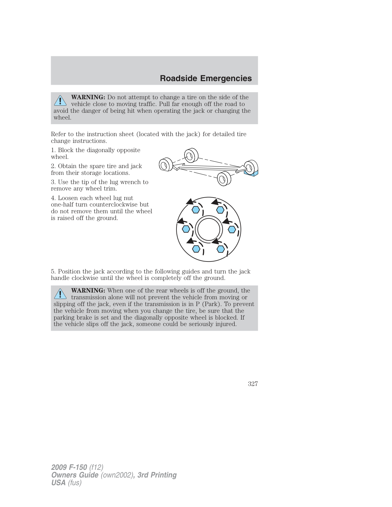
WARNING: Refer to Tire pressure monitoring system (TPMS) in the Tires, Wheels and Loading chapter for important information. If the tire pressure monitor sensor becomes damaged, it will no longer function.
###### Dissimilar spare tire/wheel information
WARNING: Failure to follow these guidelines could result in an increased risk of loss of vehicle control, injury or death.
If you have a dissimilar spare tire/wheel, then it is intended for temporary use only. This means that if you need to use it, you should replace it as soon as possible with a road tire/wheel that is the same size and type as the road tires and wheels that were originally provided by Ford. If the dissimilar spare tire or wheel is damaged, it should be replaced rather than repaired.
A dissimilar spare tire/wheel is defined as a spare tire and/or wheel that is different in brand, size or appearance from the road tires and wheels and can be one of three types:
When driving with one of the dissimilar spare tires listed above, do not:
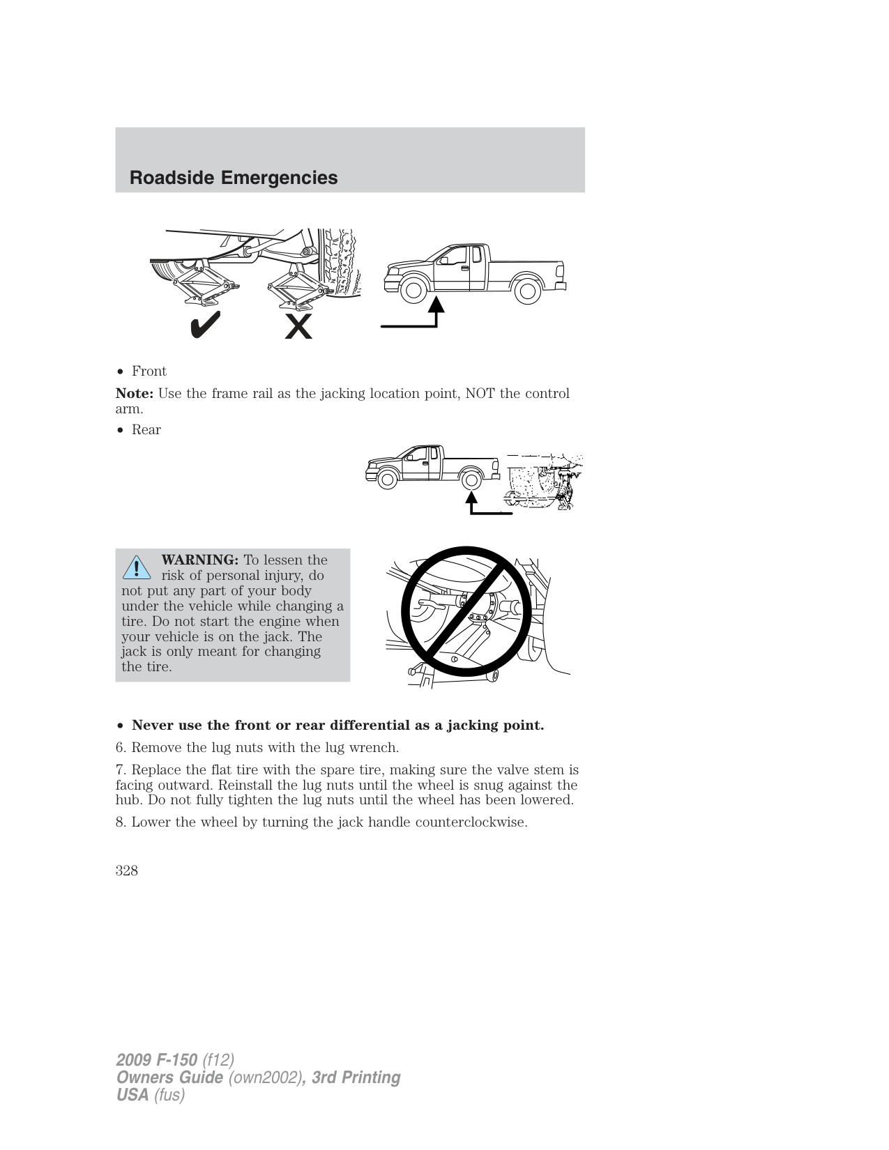
Use of one of the dissimilar spare tires listed above at any one wheel location can lead to impairment of the following:
###### 3. Full-size dissimilar spare without label on wheelWhen driving with the full-size dissimilar spare tire/wheel, do not:
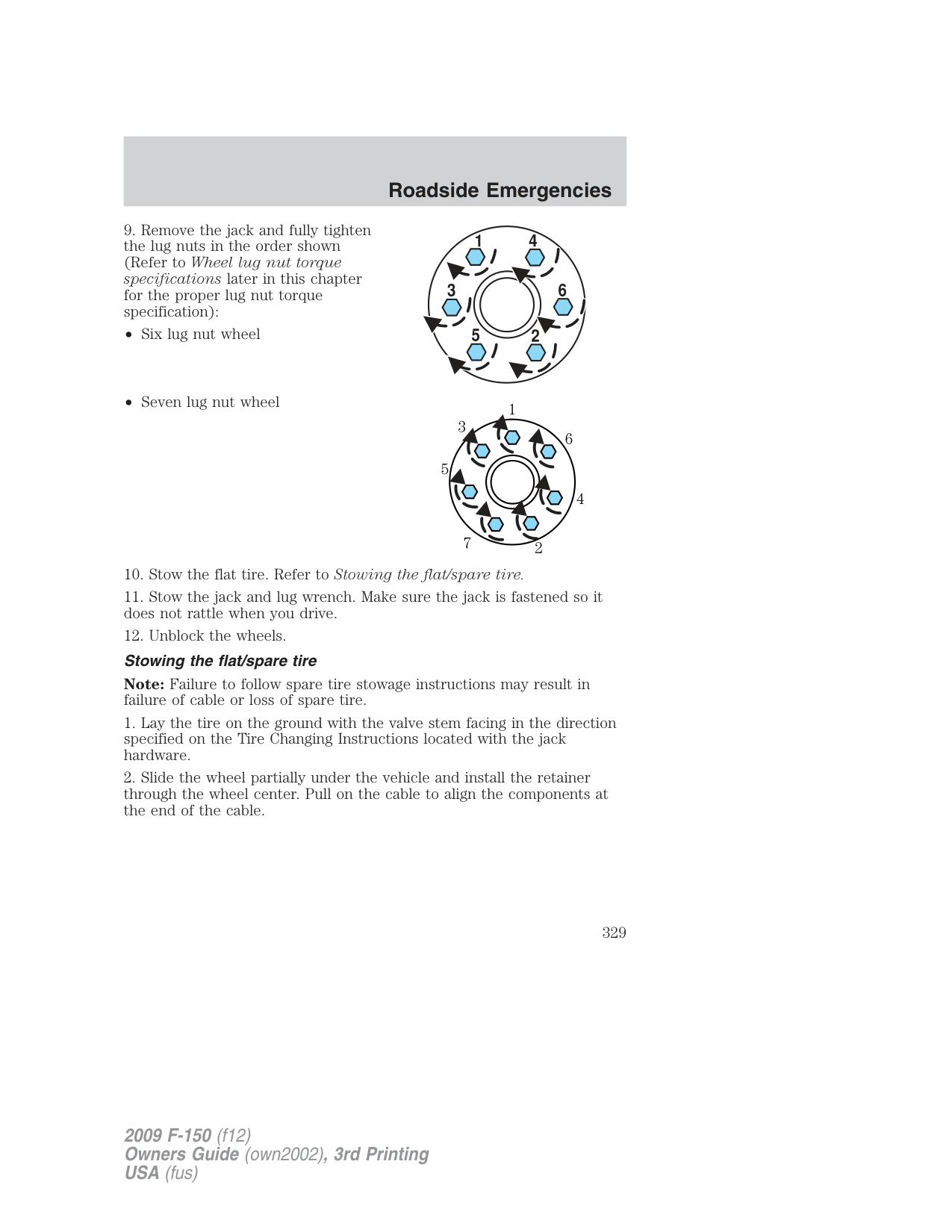
When driving with the full-size dissimilar spare tire/wheel additional caution should be given to:
Drive cautiously when using a full-size dissimilar spare tire/wheel and seek service as soon as possible.
###### Stopping and securing the vehicle
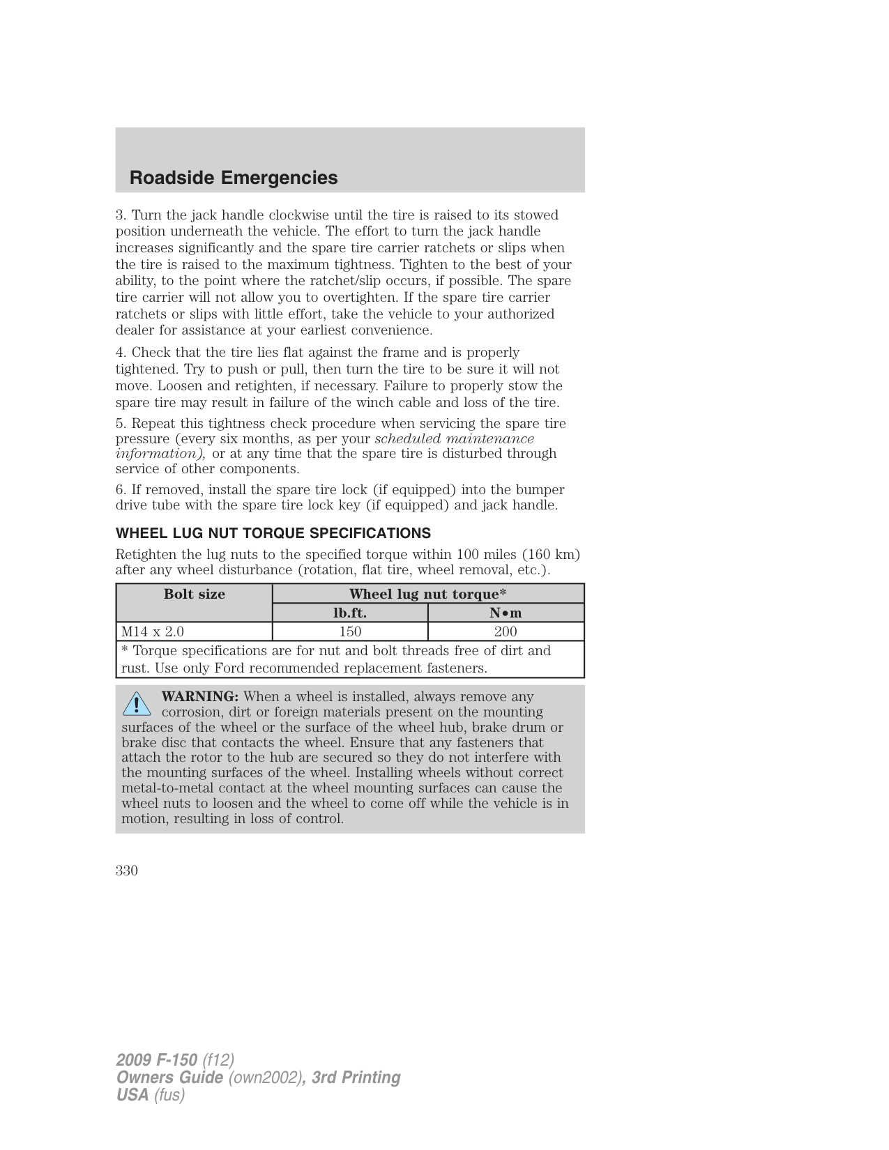
###### Location of the spare tire and tools
The spare tire is located under the vehicle, just forward of the rear bumper. The jack, jack handle and lug wrench are located in the following locations:
|Body Style|Location| |---|---| |Regular Cab|Attached to a floor bracket behind the driver’s seat| |SuperCab|Attached to a floor bracket under the rear seat on the driver’s side| |SuperCrew|In a plastic box in the floor under the rear seat|
###### To remove the jack on Regular Cab and SuperCab models:
Remove the wing nut and turn the jack screw counterclockwise to release pressure before removing the jack from the bracket.
###### To remove the jack on SuperCrew models:
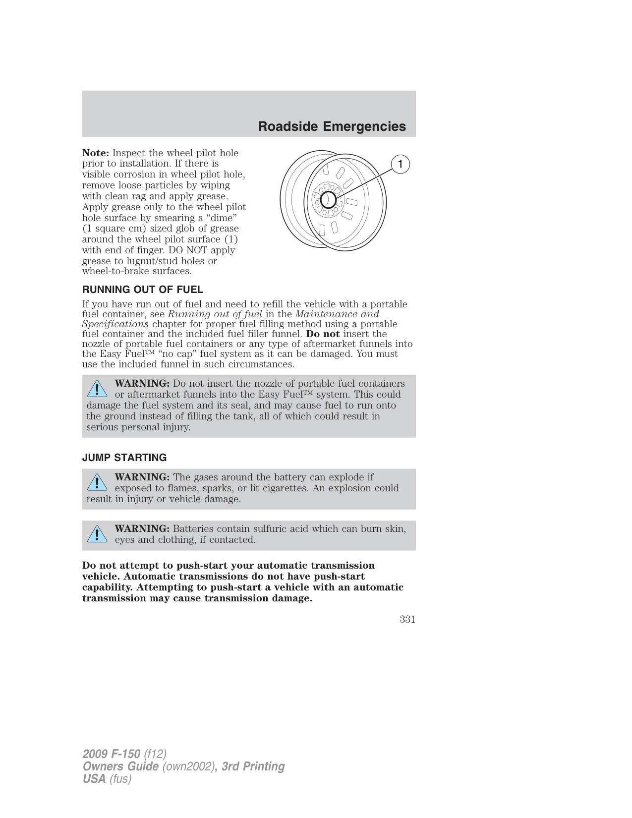

WARNING: To help prevent the vehicle from moving when you change a tire, be sure the parking brake is set, then block (in
both directions) the wheel that is diagonally opposite (other side and end of the vehicle) to the tire being changed.
WARNING: If the vehicle slips off the jack, you or someone else could be seriously injured.
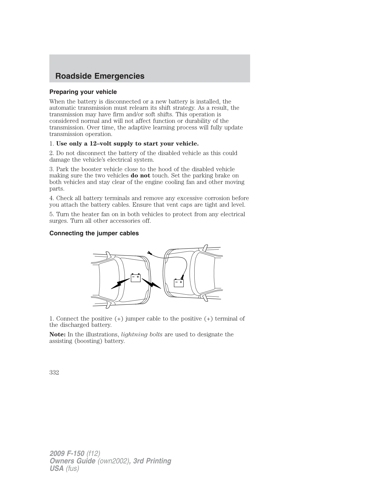
WARNING: Do not attempt to change a tire on the side of the vehicle close to moving traffic. Pull far enough off the road to
avoid the danger of being hit when operating the jack or changing the wheel.
Refer to the instruction sheet (located with the jack) for detailed tire change instructions.
WARNING: When one of the rear wheels is off the ground, the transmission alone will not prevent the vehicle from moving or
slipping off the jack, even if the transmission is in P (Park). To prevent the vehicle from moving when you change the tire, be sure that the parking brake is set and the diagonally opposite wheel is blocked. If the vehicle slips off the jack, someone could be seriously injured.
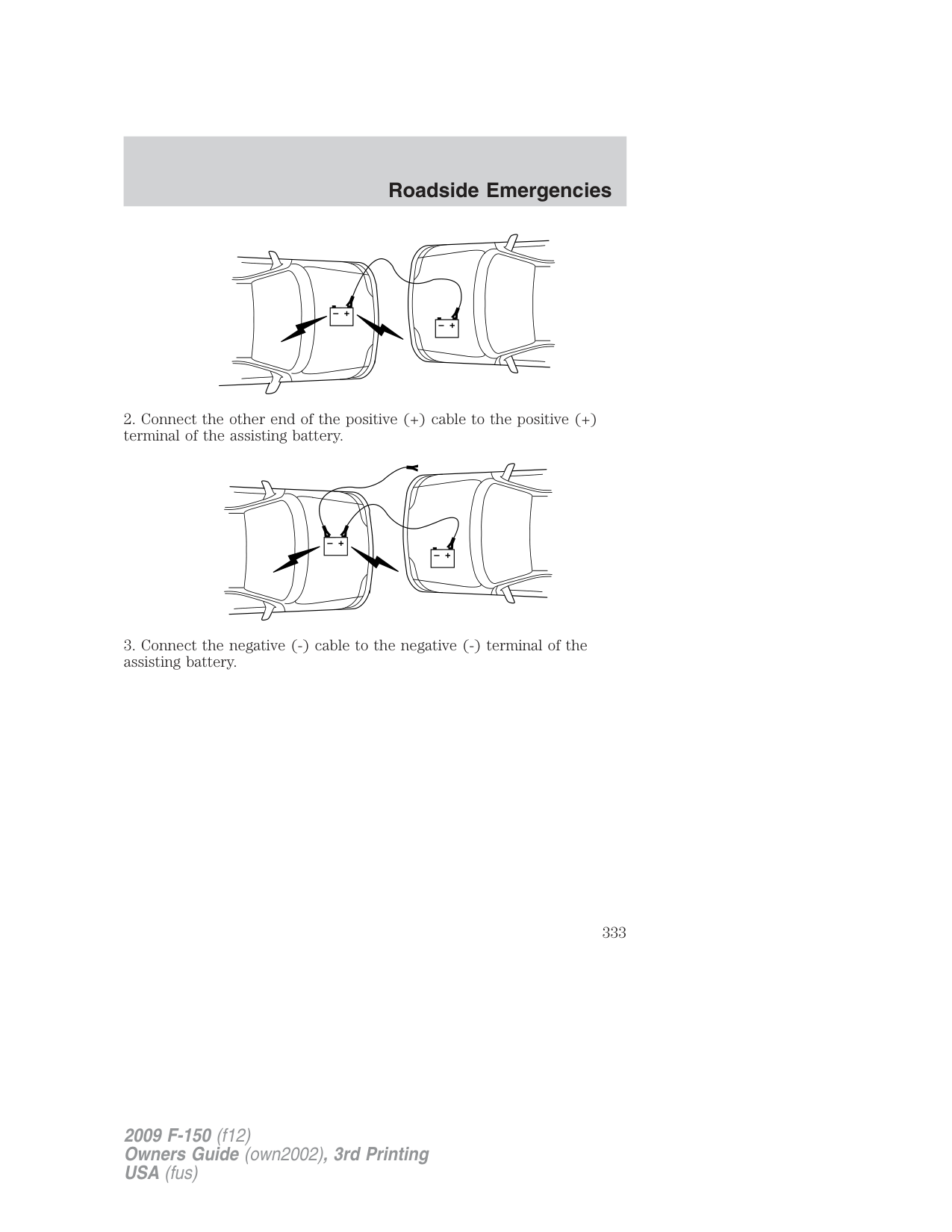
Note: Use the frame rail as the jacking location point, NOT the control arm.
WARNING: To lessen the risk of personal injury, do
not put any part of your body under the vehicle while changing a tire. Do not start the engine when your vehicle is on the jack. The jack is only meant for changing the tire.

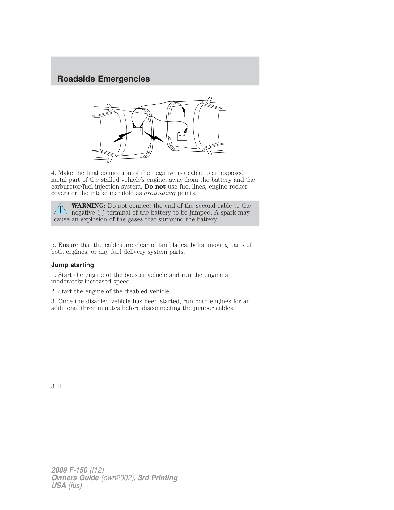
Note: Failure to follow spare tire stowage instructions may result in failure of cable or loss of spare tire.
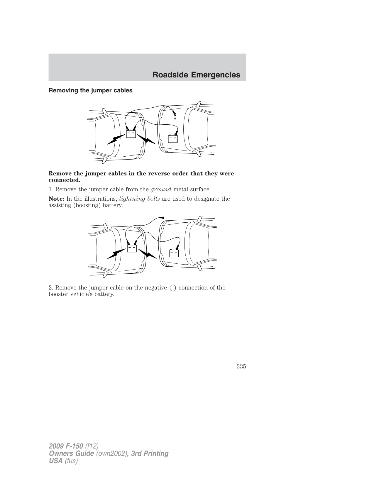
###### WHEEL LUG NUT TORQUE SPECIFICATIONS
Retighten the lug nuts to the specified torque within 100 miles (160 km) after any wheel disturbance (rotation, flat tire, wheel removal, etc.).
|Bolt size|Wheel lug nut torque*|Wheel lug nut torque*| |---|---|---| |Bolt size|lb.ft.|N•m| |M14 x 2.0|150|200| |* Torque specifications are for nut and bolt threads free of dirt and rust. Use only Ford recommended replacement fasteners.|* Torque specifications are for nut and bolt threads free of dirt and rust. Use only Ford recommended replacement fasteners.|* Torque specifications are for nut and bolt threads free of dirt and rust. Use only Ford recommended replacement fasteners.|
WARNING: When a wheel is installed, always remove any corrosion, dirt or foreign materials present on the mounting
surfaces of the wheel or the surface of the wheel hub, brake drum or brake disc that contacts the wheel. Ensure that any fasteners that attach the rotor to the hub are secured so they do not interfere with the mounting surfaces of the wheel. Installing wheels without correct metal-to-metal contact at the wheel mounting surfaces can cause the wheel nuts to loosen and the wheel to come off while the vehicle is in motion, resulting in loss of control.
Note: Inspect the wheel pilot hole prior to installation. If there is visible corrosion in wheel pilot hole, remove loose particles by wiping with clean rag and apply grease. Apply grease only to the wheel pilot hole surface by smearing a “dime” (1 square cm) sized glob of grease around the wheel pilot surface (1) with end of finger. DO NOT apply grease to lugnut/stud holes or wheel-to-brake surfaces.
RUNNING OUT OF FUEL If you have run out of fuel and need to refill the vehicle with a portable fuel container, see Running out of fuel in the Maintenance and Specifications chapter for proper fuel filling method using a portable fuel container and the included fuel filler funnel. Do not insert the nozzle of portable fuel containers or any type of aftermarket funnels into the Easy Fuel™ “no cap” fuel system as it can be damaged. You must use the included funnel in such circumstances.
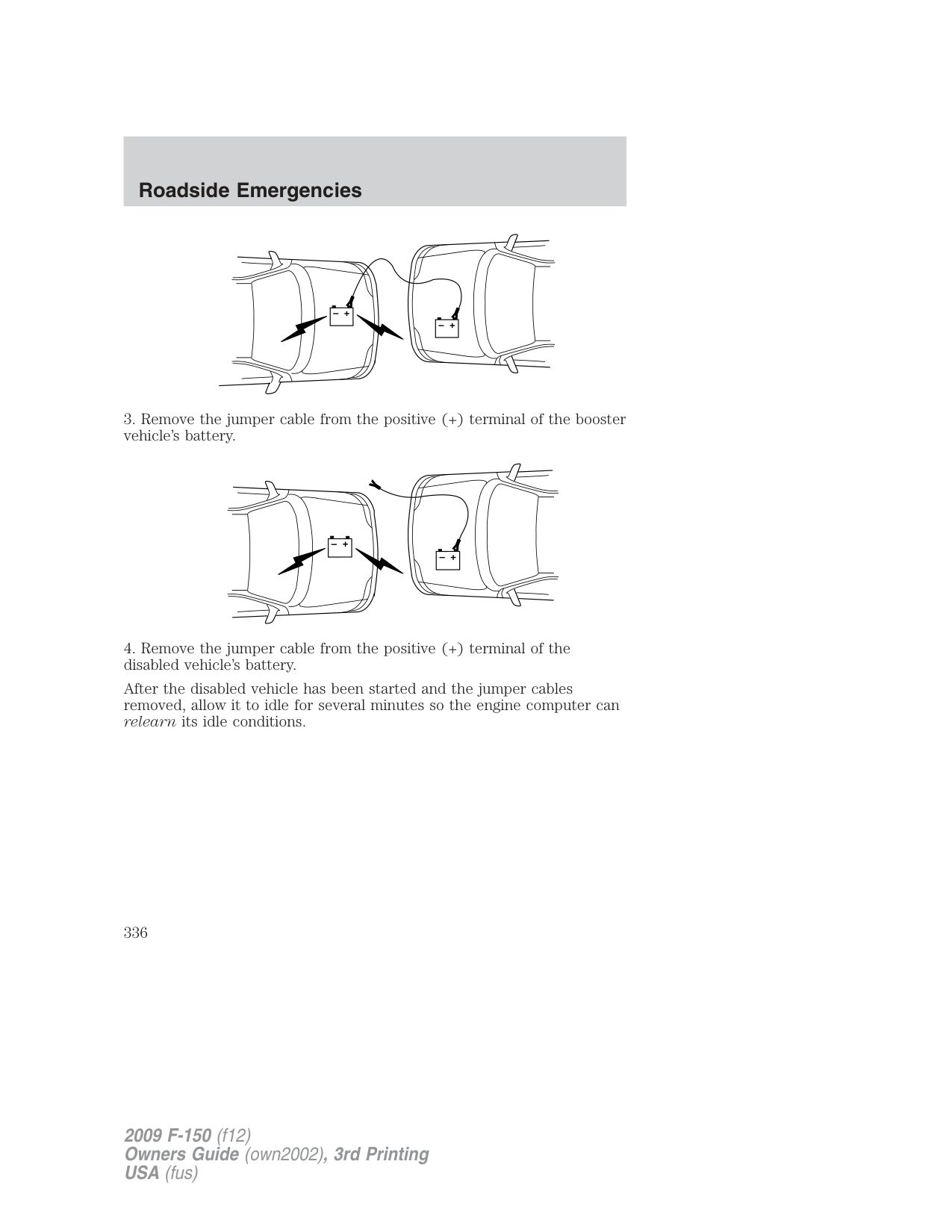
WARNING: Do not insert the nozzle of portable fuel containers or aftermarket funnels into the Easy Fuel™ system. This could
damage the fuel system and its seal, and may cause fuel to run onto the ground instead of filling the tank, all of which could result in serious personal injury.
###### JUMP STARTING
WARNING: The gases around the battery can explode if exposed to flames, sparks, or lit cigarettes. An explosion could
result in injury or vehicle damage.
WARNING: Batteries contain sulfuric acid which can burn skin, eyes and clothing, if contacted.
Do not attempt to push-start your automatic transmission vehicle. Automatic transmissions do not have push-start capability. Attempting to push-start a vehicle with an automatic transmission may cause transmission damage.
###### Preparing your vehicle
When the battery is disconnected or a new battery is installed, the automatic transmission must relearn its shift strategy. As a result, the transmission may have firm and/or soft shifts. This operation is considered normal and will not affect function or durability of the transmission. Over time, the adaptive learning process will fully update transmission operation.
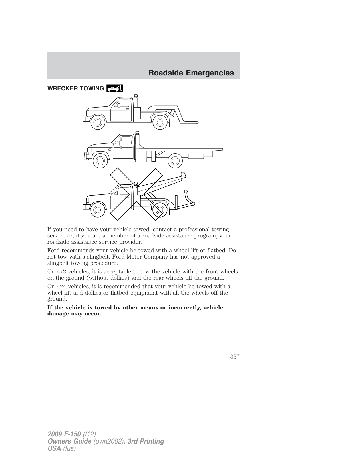
|+
–| |---|
|+
–| |---|
Note: In the illustrations, lightning bolts are used to designate the assisting (boosting) battery.
|+
–| |---|
|+
–| |---|
|+
–| |---|
|+
–| |---|
|+
–| |---|
|+
–| |---|
WARNING: Do not connect the end of the second cable to the negative (-) terminal of the battery to be jumped. A spark may
cause an explosion of the gases that surround the battery.
Removing the jumper cables
|+
–| |---|
|+
–| |---|
Remove the jumper cables in the reverse order that they were connected.
Note: In the illustrations, lightning bolts are used to designate the assisting (boosting) battery.
|+
–|
|---|
|+
–| |---|
|+
–| |---|
|+
–| |---|
|+
–|
|---|
|+
–| |---|
After the disabled vehicle has been started and the jumper cables removed, allow it to idle for several minutes so the engine computer can relearn its idle conditions.
###### WRECKER TOWING
| | | |---|---| | | |
If you need to have your vehicle towed, contact a professional towing service or, if you are a member of a roadside assistance program, your roadside assistance service provider.
Ford recommends your vehicle be towed with a wheel lift or flatbed. Do not tow with a slingbelt. Ford Motor Company has not approved a slingbelt towing procedure.
On 4x2 vehicles, it is acceptable to tow the vehicle with the front wheels on the ground (without dollies) and the rear wheels off the ground.
On 4x4 vehicles, it is recommended that your vehicle be towed with a wheel lift and dollies or flatbed equipment with all the wheels off the ground.
If the vehicle is towed by other means or incorrectly, vehicle damage may occur.
###### Emergency towing
In case of a roadside emergency with a disabled vehicle (without access to wheel dollies, car hauling trailer, or flatbed transport vehicle) your vehicle (regardless of transmission powertrain configuration) can be flat towed (all wheels on the ground) under the following conditions:
GETTING THE SERVICES YOU NEED Warranty repairs to your vehicle must be performed by an authorized Ford, Lincoln, or Mercury dealer. While any authorized dealer handling your vehicle line will provide warranty service, we recommend you return to your selling authorized dealer who wants to ensure your continued satisfaction.
Please note that certain warranty repairs require special training and/or equipment, so not all authorized dealers are authorized to perform all warranty repairs. This means that, depending on the warranty repair needed, you may have to take your vehicle to another authorized dealer. A reasonable time must be allowed to perform a repair after taking your vehicle to the authorized dealer. Repairs will be made using Ford or Motorcraft parts, or remanufactured or other parts that are authorized by Ford.
###### Away from home
If you are away from home when your vehicle needs service, contact the Ford Customer Relationship Center or use the online resources listed below to find the nearest authorized dealer.
In the United States: Mailing address Ford Motor Company Customer Relationship Center P.O. Box 6248 Dearborn, MI 48121 Telephone 1-800-392-3673 (FORD) (TDD for the hearing impaired: 1-800-232-5952) Online Additional information and resources are available online at www.genuineservice.com.
In Canada: Mailing address (Ford vehicles) Customer Relationship Centre Ford Motor Company of Canada, Limited P.O. Box 2000 Oakville, Ontario L6J 5E4 Telephone 1-800-565-3673 (FORD) Online www.ford.ca Mailing address (Lincoln vehicles) Lincoln Centre Ford Motor Company of Canada, Limited P.O. Box 2000 Oakville, Ontario L6J 5E4 Telephone 1-800-387-9333 Online www.lincolncanada.com Additional assistance If you have questions or concerns, or are unsatisfied with the service you are receiving, follow these steps:
In order to help you serve you better, please have the following information available when contacting a Customer Relationship Center:
In some states, you must directly notify Ford in writing before pursuing remedies under your state’s warranty laws. Ford is also allowed a final repair attempt in some states.
In the United States, a warranty dispute must be submitted to the BBB AUTO LINE before taking action under the Magnuson-Moss Warranty Act, or to the extent allowed by state law, before pursuing replacement or repurchase remedies provided by certain state laws. This dispute handling procedure is not required prior to enforcing state created rights or other rights which are independent of the Magnuson-Moss Warranty Act or state replacement or repurchase laws.
###### IN CALIFORNIA (U.S. ONLY)
California Civil Code Section 1793.2(d) requires that, if a manufacturer or its representative is unable to repair a motor vehicle to conform to the vehicle’s applicable express warranty after a reasonable number of attempts, the manufacturer shall be required to either replace the vehicle with one substantially identical or repurchase the vehicle and reimburse the buyer in an amount equal to the actual price paid or payable by the consumer (less a reasonable allowance for consumer use). The consumer has the right to choose whether to receive a refund or replacement vehicle.
California Civil Code Section 1793.22(b) presumes that the manufacturer has had a reasonable number of attempts to conform the vehicle to its applicable express warranties if, within the first 18 months of ownership of a new vehicle or the first 18,000 miles (29,000 km), whichever occurs first:
In the case of 1 or 2 above, the consumer must also notify the manufacturer of the need for the repair of the nonconformity at the following address:
Ford Motor Company 16800 Executive Plaza Drive Mail Drop 3NE-B Dearborn, MI 48126
###### THE BETTER BUSINESS BUREAU (BBB) AUTO LINE PROGRAM (U.S. ONLY)
Your satisfaction is important to Ford Motor Company and to your dealer. If a warranty concern has not been resolved using the three-step
procedure outlined on the first page of the Customer Assistance section, you may be eligible to participate in the BBB AUTO LINE program.
The BBB AUTO LINE program consists of two parts – mediation and arbitration. During mediation, a representative of the BBB will contact both you and Ford Motor Company to explore options for settlement of the claim. If an agreement is not reached during mediation and your claim is eligible, you may participate in the arbitration process. An arbitration hearing will be scheduled so that you can present your case in an informal setting before an impartial person. The arbitrator will consider the testimony provided and make a decision after the hearing.
You are not bound by the decision, but should you choose to accept the BBB AUTO LINE decision, Ford must abide by the accepted decision as well. Disputes submitted to the BBB AUTO LINE program are usually decided within forty days after you file your claim with the BBB.
BBB AUTO LINE Application: Using the information provided below, please call or write to request a program application. You will be asked for your name and address, general information about your new vehicle, information about your warranty concerns, and any steps you have already taken to try to resolve them. A Customer Claim Form will be mailed that will need to be completed, signed and returned to the BBB along with proof of ownership. Upon receipt, the BBB will review the claim for eligibility under the Program Summary Guidelines.
You can get more information by calling BBB AUTO LINE at 1-800-955-5100, or writing to:
BBB AUTO LINE 4200 Wilson Boulevard, Suite 800 Arlington, Virginia 22203–1833
BBB AUTO LINE applications can also be requested by calling the Ford Motor Company Customer Relationship Center at 1-800-392-3673.
Note: Ford Motor Company reserves the right to change eligibility limitations, modify procedures, or to discontinue this process at any time without notice and without obligation.
###### UTILIZING THE MEDIATION/ARBITRATION PROGRAM (CANADA ONLY)
For vehicles delivered to authorized Canadian dealers. In those cases where you continue to feel that the efforts by Ford of Canada and the authorized dealer to resolve a factory-related vehicle service concern have been unsatisfactory, Ford of Canada participates in an impartial third party mediation/arbitration program administered by the Canadian Motor Vehicle Arbitration Plan (CAMVAP).
The CAMVAP program is a straight-forward and relatively speedy alternative to resolve a disagreement when all other efforts to produce a settlement have failed. This procedure is without cost to you and is designed to eliminate the need for lengthy and expensive legal proceedings.
In the CAMVAP program, impartial third-party arbitrators conduct hearings at mutually convenient times and places in an informal environment. These impartial arbitrators review the positions of the parties, make decisions and, when appropriate, render awards to resolve disputes. CAMVAP decisions are fast, fair, and final as the arbitrator’s award is binding both to you and Ford of Canada.
CAMVAP services are available in all territories and provinces. For more information, without charge or obligation, call your CAMVAP Provincial Administrator directly at 1-800-207-0685.
###### FORD EXTENDED SERVICE PLAN
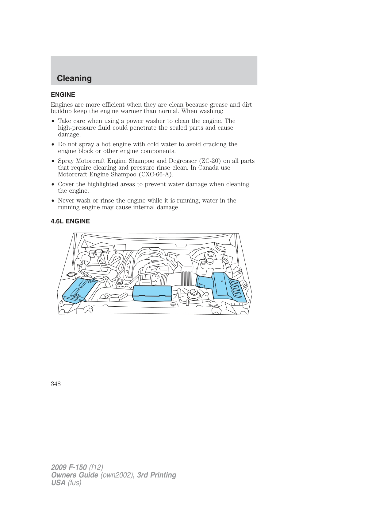
You can get more protection for your new car or light truck by purchasing Ford Extended Service Plan (Ford ESP) coverage. It provides the following:
Warranty expires. You may purchase Ford ESP from any participating authorized dealer. There are several plans available in various time, distance and deductible combinations which can be tailored to fit your own driving needs. Ford ESP also offers reimbursement benefits for towing and rental coverage.
When you buy Ford ESP, you receive Peace-of-Mind protection throughout the United States and Canada, provided by a network of more than 4,600 participating authorized dealers.
If you did not take advantage of the Ford Extended Service Plan at the time of purchasing your vehicle, you may still be eligible. Since this information is subject to change, please ask your authorized dealer for complete details about Ford Extended Service Plan coverage options, or visit the Ford ESP website at www.ford-esp.com.
GETTING ASSISTANCE OUTSIDE THE U.S. AND CANADA Before exporting your vehicle to a foreign country, contact the appropriate foreign embassy or consulate. These officials can inform you of local vehicle registration regulations and where to find unleaded fuel.
If you cannot find unleaded fuel or can only get fuel with an anti-knock index lower than is recommended for your vehicle, contact a regional office or owner relations/customer relationship office.
The use of leaded fuel in your vehicle without proper conversion may damage the effectiveness of your emission control system and may cause engine knocking or serious engine damage. Ford Motor Company/Ford of Canada is not responsible for any damage caused by use of improper fuel. Using leaded fuel may also result in difficulty importing your vehicle back into the U.S.
If your vehicle must be serviced while you are traveling or living in Central America, the Caribbean, or the Middle East, contact the nearest authorized dealer. If the authorized dealer cannot help you, contact:
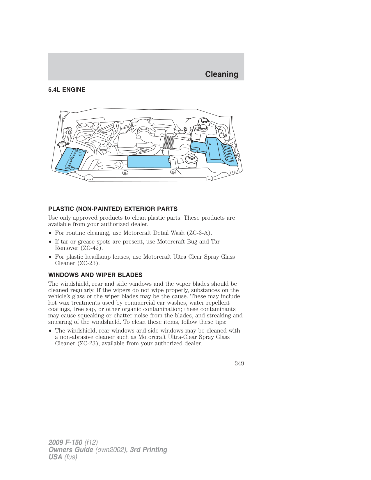
FORD MOTOR COMPANY FORD EXPORT OPERATIONS 1555 Fairlane Drive Fairlane Business Park #3 Allen Park, Michigan 48101
If you are in another foreign country, contact the nearest authorized dealer. If the authorized dealer employees cannot help you, they can direct you to the nearest Ford affiliate office.
If you buy your vehicle in North America and then relocate outside of the U.S. or Canada, register your vehicle identification number (VIN) and new address with Ford Motor Company Export Operations.
Customers in the U.S. should call 1-800-392-3673. ORDERING ADDITIONAL OWNER’S LITERATURE To order the publications in this portfolio, contact Helm, Incorporated at: HELM, INCORPORATED P.O. Box 07150 Detroit, Michigan 48207 Or to order a free publication catalog, call toll free: 1-800-782-4356 Monday-Friday 8:00 a.m. - 6:00 p.m. EST Helm, Incorporated can also be reached by their website: www.helminc.com.
(Items in this catalog may be purchased by credit card, check or money order.)
###### Obtaining a French owner’s guide
French Owner’s Guides can be obtained from your authorized dealer or by writing to: Ford Motor Company of Canada, Limited Service Publications CHQ202 The Canadian Road P.O. Box 2000 Oakville, ON, Canada L6J 5E4
###### REPORTING SAFETY DEFECTS (U.S. ONLY)
If you believe that your vehicle has a defect which could cause a crash or could cause injury or death, you should immediately inform the National Highway Traffic Safety Administration (NHTSA) in addition to notifying Ford Motor Company.
If NHTSA receives similar complaints, it may open an investigation, and if it finds that a safety defect exists in a group of vehicles, it may order a recall and remedy campaign. However, NHTSA cannot become involved in individual problems between you, your dealer, or Ford Motor Company.
To contact NHTSA, you may call the Vehicle Safety Hotline toll-free at 1–888–327–4236 (TTY: 1–800–424–9153); go to http://www.safercar.gov; or write to:
Administrator 1200 New Jersey Avenue, Southeast Washington, D.C. 20590
You can also obtain other information about motor vehicle safety from http://www.safercar.gov.
###### REPORTING SAFETY DEFECTS (CANADA ONLY)
If you believe that your vehicle has a defect which could cause a crash or could cause injury or death, you should immediately inform Transport Canada, using their toll-free number: 1–800–333–0510.
WASHING THE EXTERIOR Wash your vehicle regularly with cool or lukewarm water and a neutral pH shampoo, such as Motorcraft Detail Wash (ZC-3-A), which is available from your authorized dealer.
###### Exterior chrome
###### WAXING
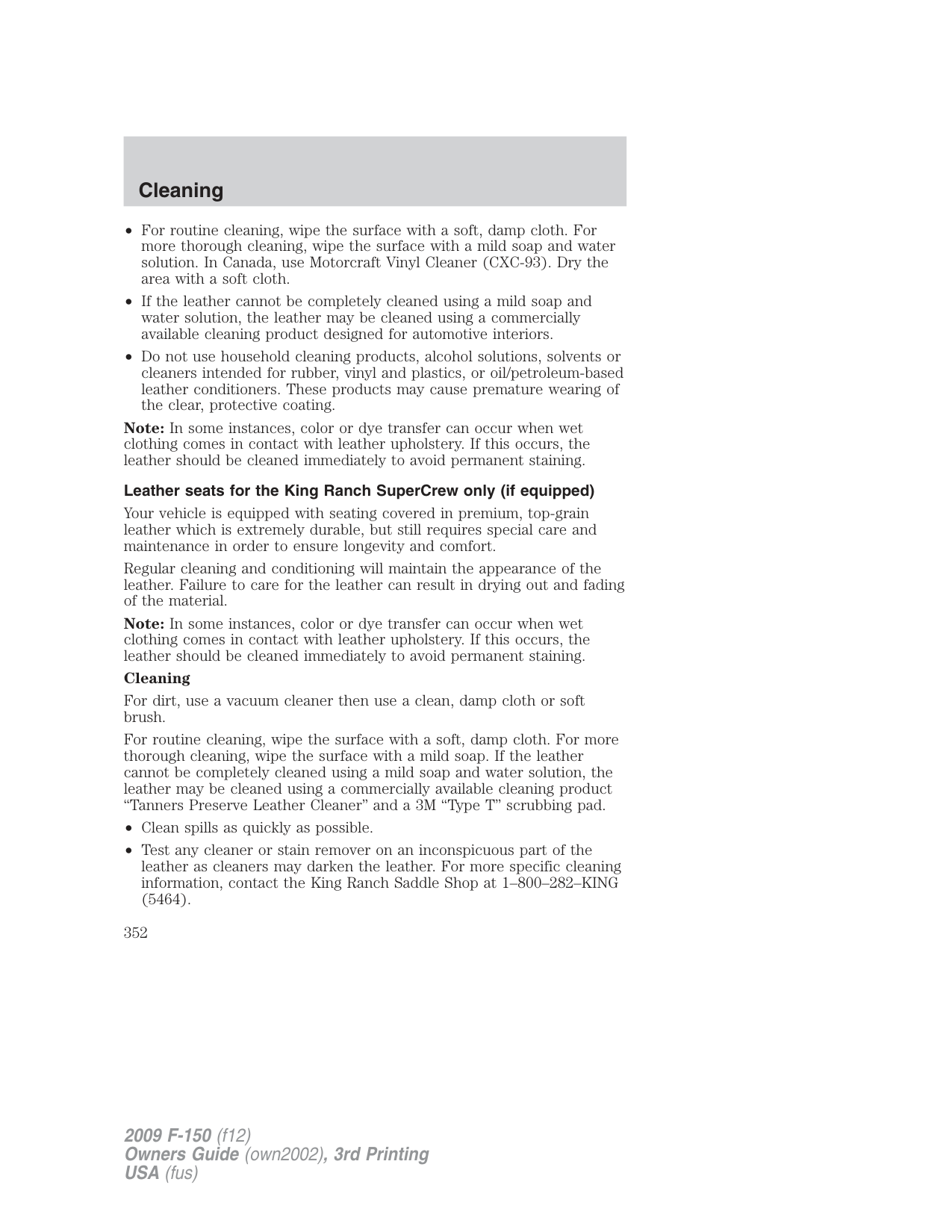
###### PAINT CHIPS
Your authorized dealer has touch-up paint to match your vehicle’s color. Take your color code (printed on a sticker in the driver’s door jamb) to your authorized dealer to ensure you get the correct color.
ALUMINUM WHEELS AND WHEEL COVERS
Aluminum wheels and wheel covers are coated with a clearcoat paint finish. In order to maintain their shine:
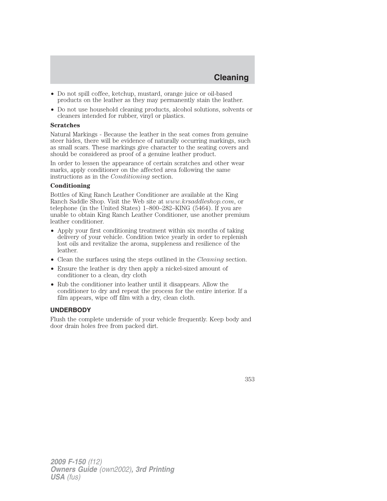
###### ENGINE
Engines are more efficient when they are clean because grease and dirt buildup keep the engine warmer than normal. When washing:
###### 4.6L ENGINE
R
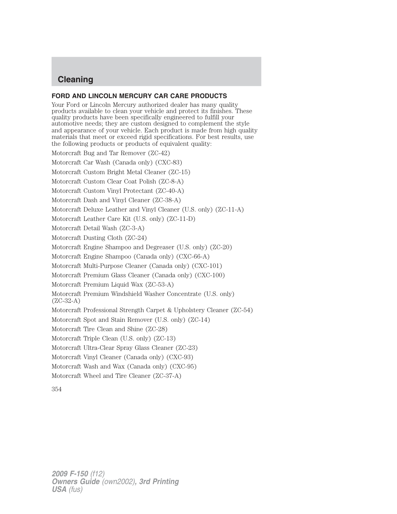
R
F
E
U
I
S
D
A
W
LY
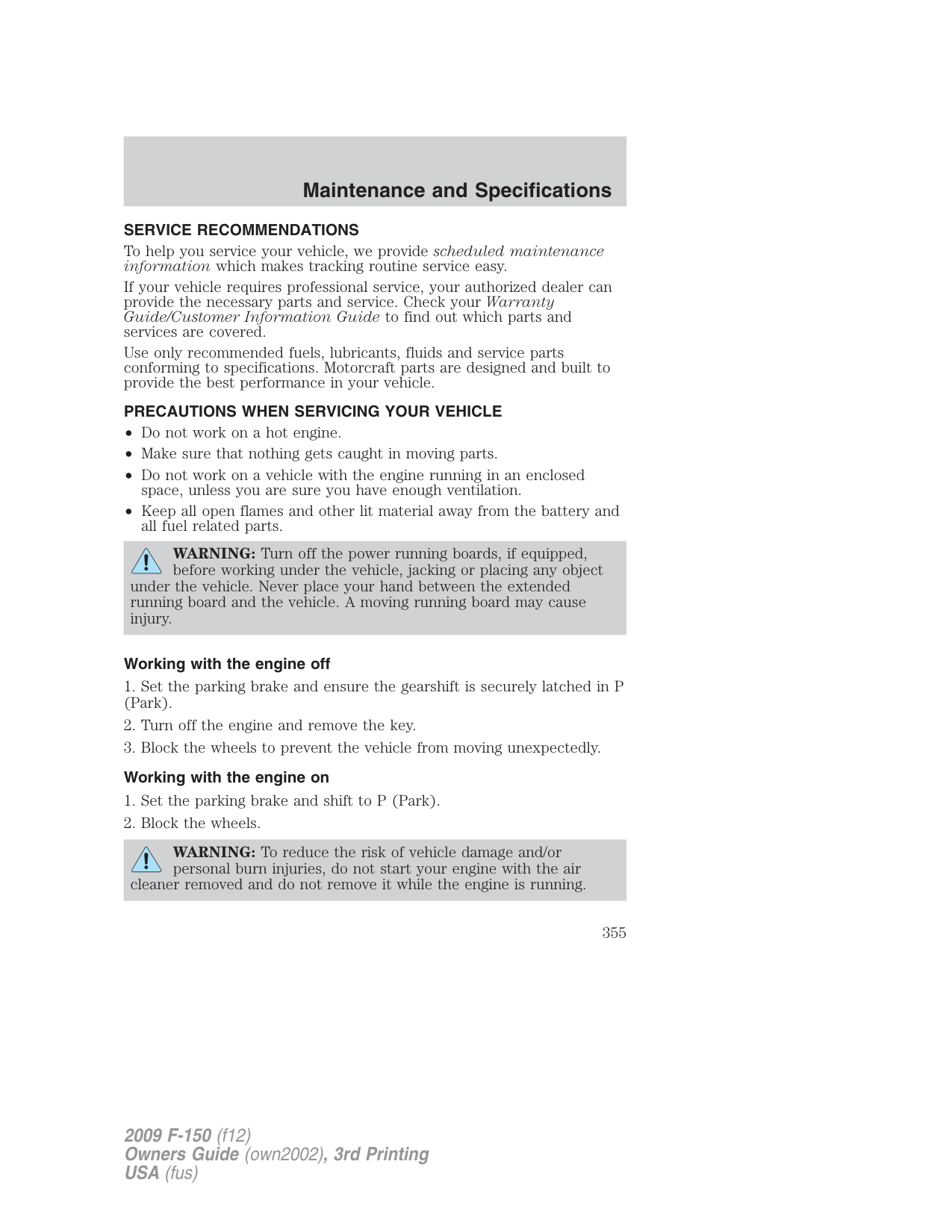
############# LY
PLASTIC (NON-PAINTED) EXTERIOR PARTS
Use only approved products to clean plastic parts. These products are available from your authorized dealer.
###### WINDOWS AND WIPER BLADES
The windshield, rear and side windows and the wiper blades should be cleaned regularly. If the wipers do not wipe properly, substances on the vehicle’s glass or the wiper blades may be the cause. These may include hot wax treatments used by commercial car washes, water repellent coatings, tree sap, or other organic contamination; these contaminants may cause squeaking or chatter noise from the blades, and streaking and smearing of the windshield. To clean these items, follow these tips:
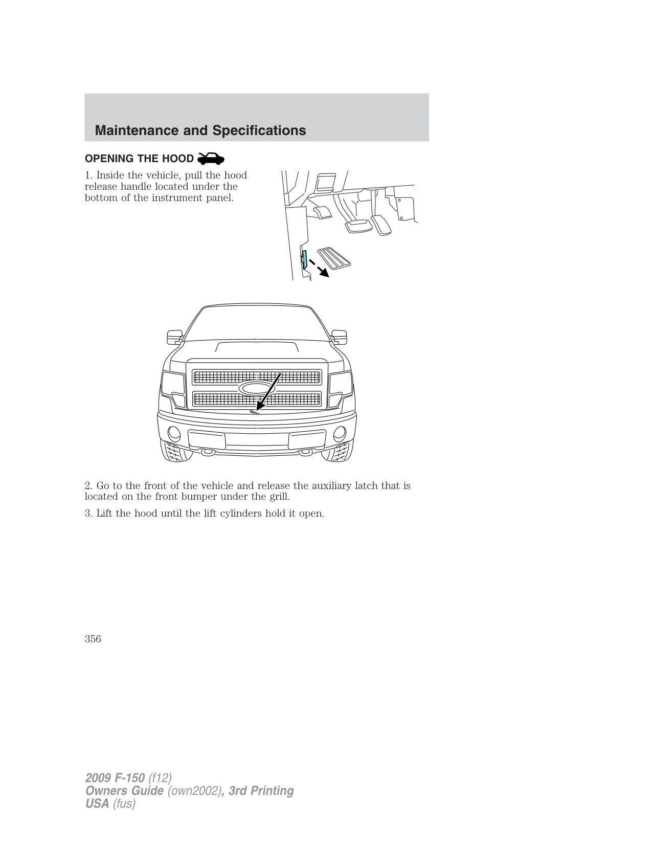
If you cannot remove those streaks after cleaning with the glass cleaner or if the wipers chatter and move in a jerky motion, clean the outer surface of the windshield and the wiper blades using a sponge or soft cloth with a neutral detergent or mild-abrasive cleaning solution. After cleaning, rinse the windshield and wiper blades with clean water. The windshield is clean if beads do not form when you rinse the windshield with water.
Do not use sharp objects, such as a razor blade, to clean the inside of the rear window or to remove decals, as it may cause damage to the rear window defroster’s heated grid lines (if equipped).
INSTRUMENT PANEL/INTERIOR TRIM AND CLUSTER LENS
Clean the instrument panel, interior trim areas and cluster lens with a clean and damp white cotton cloth, then with a clean and dry white cotton cloth; you may also use Motorcraft Dash & Vinyl Cleaner (ZC-38-A) on the instrument panel and interior trim areas.
WARNING: Do not use chemical solvents or strong detergents when cleaning the steering wheel or instrument panel to avoid
contamination of the airbag system.
If a staining liquid like coffee/juice has been spilled on the instrument panel or on interior trim surfaces, clean as follows:
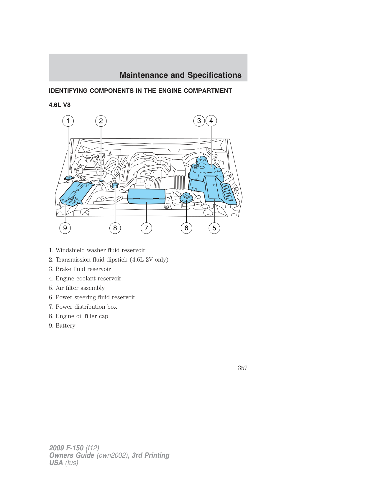
INTERIOR For fabric, carpets, cloth seats and safety belts:
WARNING: Do not use cleaning solvents, bleach or dye on the vehicle’s seatbelts, as these actions may weaken the belt
webbing.
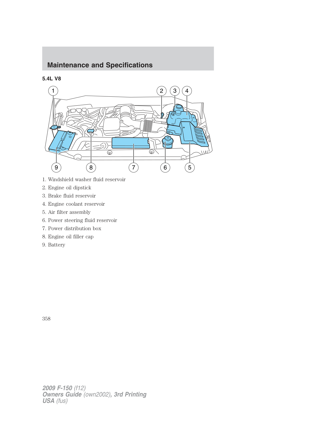
###### LEATHER SEATS (IF EQUIPPED, EXCEPT FOR THE KING RANCH SUPERCREW)
Your leather seating surfaces have a clear, protective coating over the leather.
For King Ranch SuperCrew leather seats, refer to separate section in this chapter.
Note: In some instances, color or dye transfer can occur when wet clothing comes in contact with leather upholstery. If this occurs, the leather should be cleaned immediately to avoid permanent staining.
###### Leather seats for the King Ranch SuperCrew only (if equipped)
Your vehicle is equipped with seating covered in premium, top-grain leather which is extremely durable, but still requires special care and maintenance in order to ensure longevity and comfort.
Regular cleaning and conditioning will maintain the appearance of the leather. Failure to care for the leather can result in drying out and fading of the material.
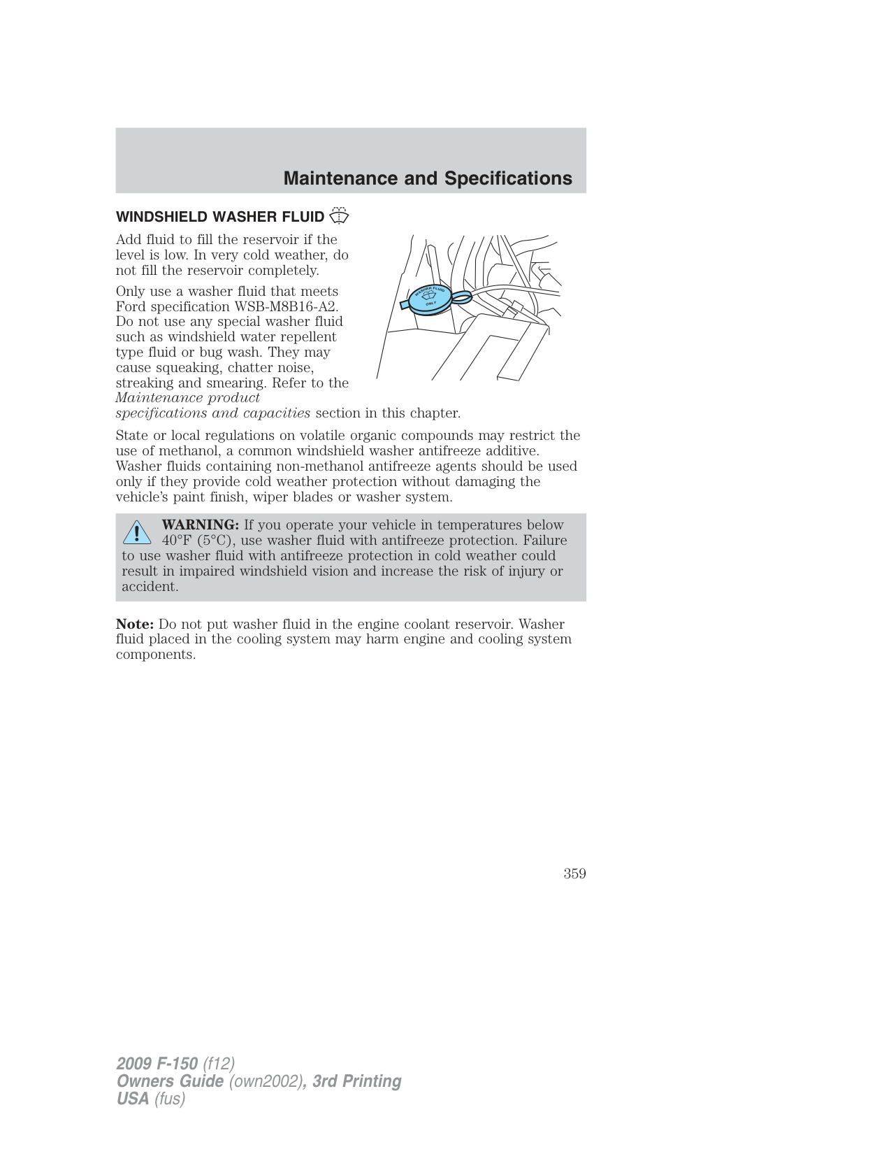
Note: In some instances, color or dye transfer can occur when wet clothing comes in contact with leather upholstery. If this occurs, the leather should be cleaned immediately to avoid permanent staining.
###### Cleaning
For dirt, use a vacuum cleaner then use a clean, damp cloth or soft brush.
For routine cleaning, wipe the surface with a soft, damp cloth. For more thorough cleaning, wipe the surface with a mild soap. If the leather cannot be completely cleaned using a mild soap and water solution, the leather may be cleaned using a commercially available cleaning product “Tanners Preserve Leather Cleaner” and a 3M “Type T” scrubbing pad.
(5464).
###### Scratches
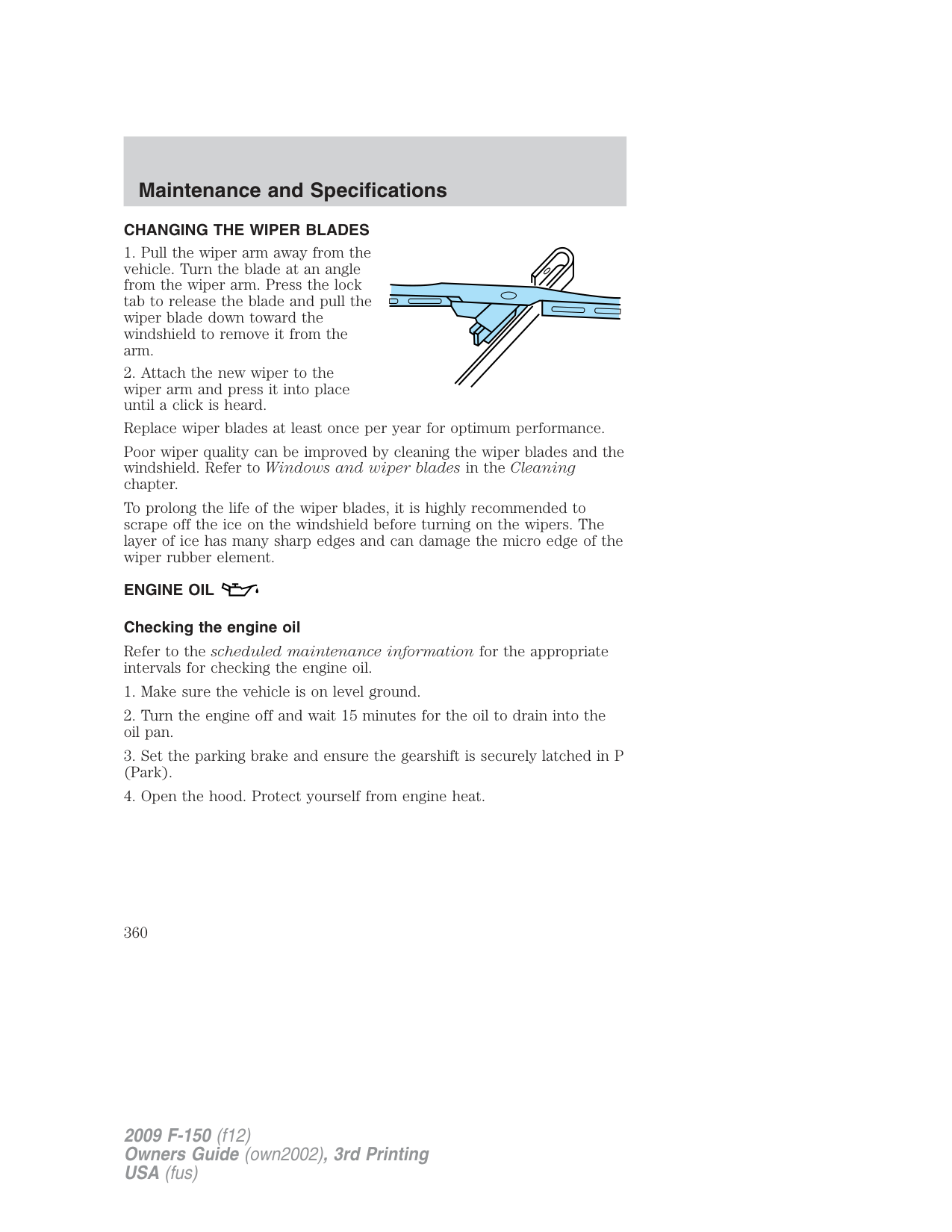
Natural Markings - Because the leather in the seat comes from genuine steer hides, there will be evidence of naturally occurring markings, such
In order to lessen the appearance of certain scratches and other wear marks, apply conditioner on the affected area following the same instructions as in the Conditioning section.
###### Conditioning
Bottles of King Ranch Leather Conditioner are available at the King Ranch Saddle Shop. Visit the Web site at www.krsaddleshop.com,or telephone (in the United States) 1–800–282–KING (5464). If you are unable to obtain King Ranch Leather Conditioner, use another premium leather conditioner.
###### UNDERBODY
Flush the complete underside of your vehicle frequently. Keep body and door drain holes free from packed dirt.
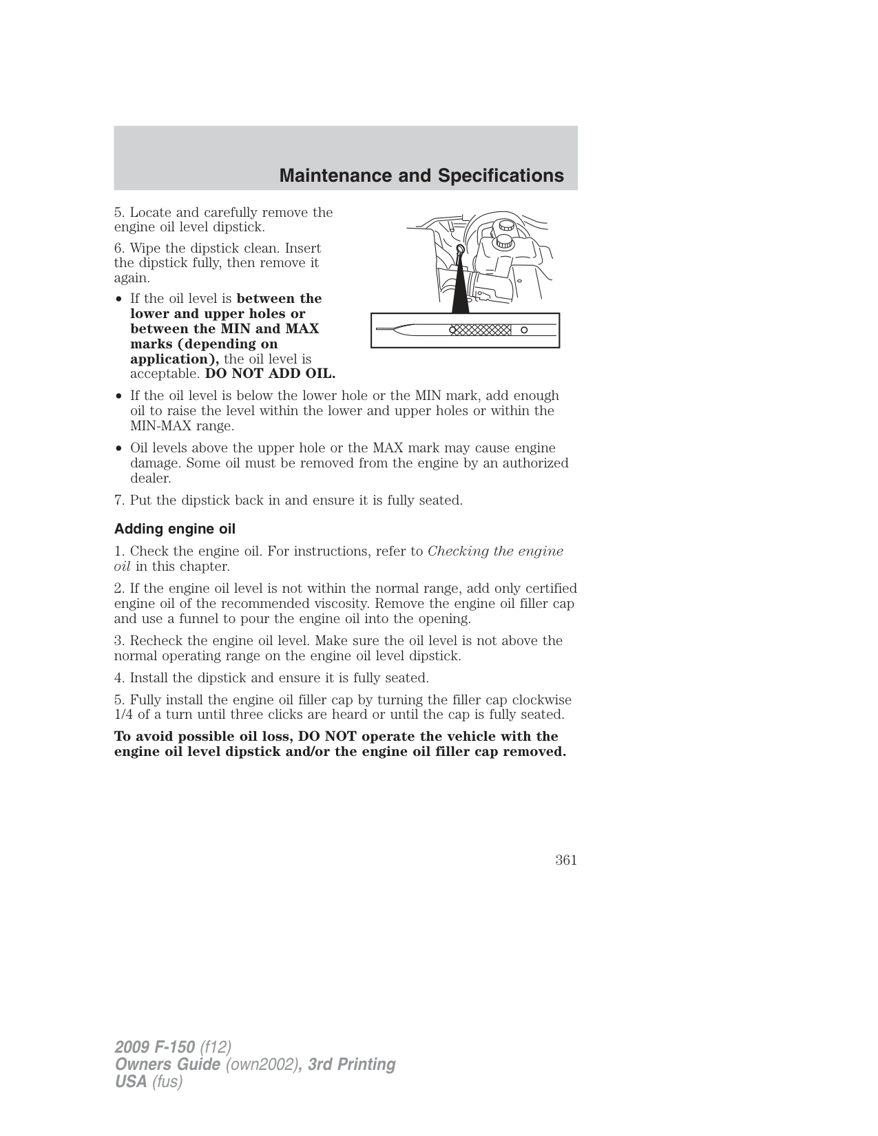
FORD AND LINCOLN MERCURY CAR CARE PRODUCTS Your Ford or Lincoln Mercury authorized dealer has many quality products available to clean your vehicle and protect its finishes. These quality products have been specifically engineered to fulfill your automotive needs; they are custom designed to complement the style and appearance of your vehicle. Each product is made from high quality materials that meet or exceed rigid specifications. For best results, use the following products or products of equivalent quality:
Motorcraft Bug and Tar Remover (ZC-42) Motorcraft Car Wash (Canada only) (CXC-83) Motorcraft Custom Bright Metal Cleaner (ZC-15) Motorcraft Custom Clear Coat Polish (ZC-8-A) Motorcraft Custom Vinyl Protectant (ZC-40-A) Motorcraft Dash and Vinyl Cleaner (ZC-38-A) Motorcraft Deluxe Leather and Vinyl Cleaner (U.S. only) (ZC-11-A) Motorcraft Leather Care Kit (U.S. only) (ZC-11-D) Motorcraft Detail Wash (ZC-3-A) Motorcraft Dusting Cloth (ZC-24) Motorcraft Engine Shampoo and Degreaser (U.S. only) (ZC-20) Motorcraft Engine Shampoo (Canada only) (CXC-66-A) Motorcraft Multi-Purpose Cleaner (Canada only) (CXC-101) Motorcraft Premium Glass Cleaner (Canada only) (CXC-100) Motorcraft Premium Liquid Wax (ZC-53-A) Motorcraft Premium Windshield Washer Concentrate (U.S. only) (ZC-32-A) Motorcraft Professional Strength Carpet & Upholstery Cleaner (ZC-54) Motorcraft Spot and Stain Remover (U.S. only) (ZC-14) Motorcraft Tire Clean and Shine (ZC-28) Motorcraft Triple Clean (U.S. only) (ZC-13) Motorcraft Ultra-Clear Spray Glass Cleaner (ZC-23) Motorcraft Vinyl Cleaner (Canada only) (CXC-93) Motorcraft Wash and Wax (Canada only) (CXC-95) Motorcraft Wheel and Tire Cleaner (ZC-37-A)
SERVICE RECOMMENDATIONS To help you service your vehicle, we provide scheduled maintenance information which makes tracking routine service easy.
If your vehicle requires professional service, your authorized dealer can provide the necessary parts and service. Check your Warranty Guide/Customer Information Guide to find out which parts and services are covered. Use only recommended fuels, lubricants, fluids and service parts conforming to specifications. Motorcraft parts are designed and built to provide the best performance in your vehicle.
###### PRECAUTIONS WHEN SERVICING YOUR VEHICLE
WARNING: Turn off the power running boards, if equipped, before working under the vehicle, jacking or placing any object
under the vehicle. Never place your hand between the extended running board and the vehicle. A moving running board may cause injury.
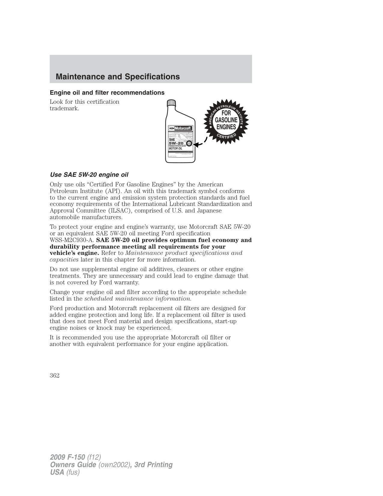
###### Working with the engine off
WARNING: To reduce the risk of vehicle damage and/or personal burn injuries, do not start your engine with the air
cleaner removed and do not remove it while the engine is running.
###### OPENING THE HOOD
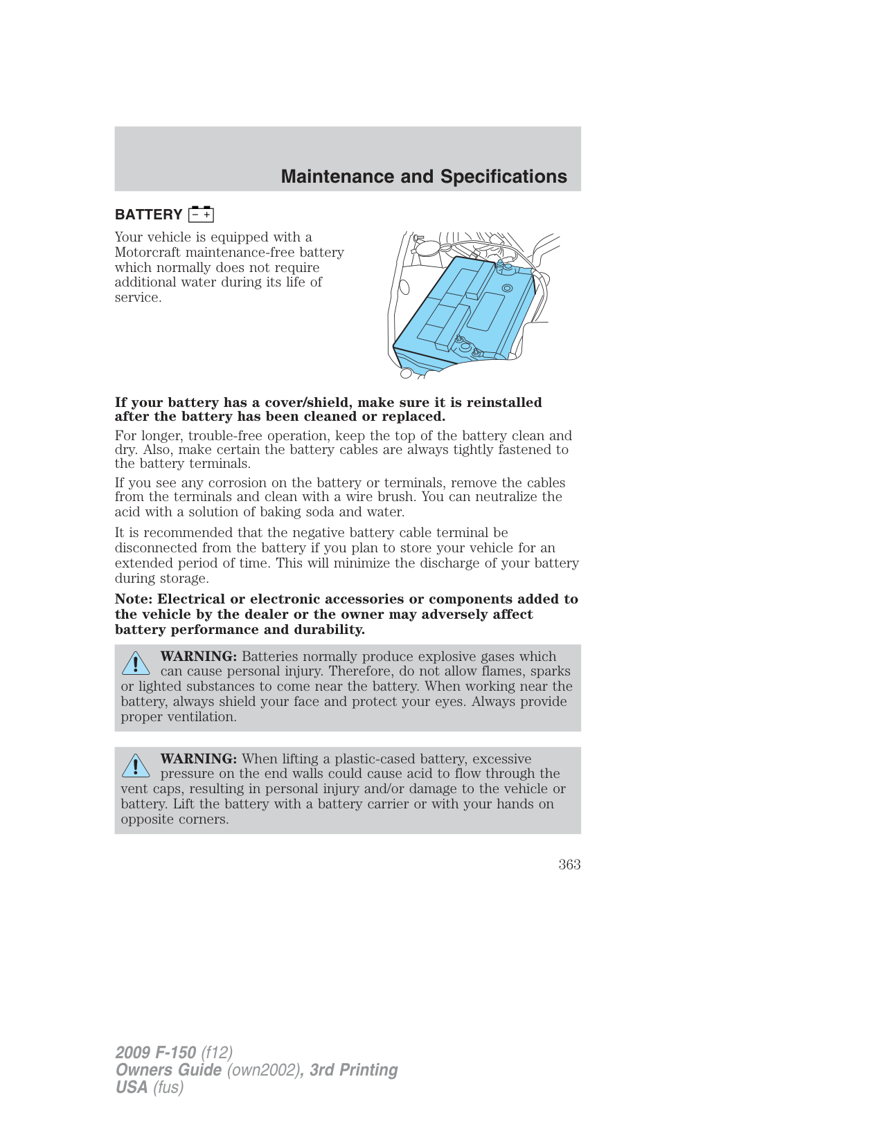
| | | | | | | | | | | | | | | | | | | | | | | | | | | | | | | | | | |---|---|---|---|---|---|---|---|---|---|---|---|---|---|---|---|---|---|---|---|---|---|---|---|---|---|---|---|---|---|---|---|---| | | | | | | | | | | | | | | | | | | | | | | | | | | | | | | | | | |
| | | | | | | | | | | | | | | | | | | | | | | | | | | | | | | | | | |---|---|---|---|---|---|---|---|---|---|---|---|---|---|---|---|---|---|---|---|---|---|---|---|---|---|---|---|---|---|---|---|---| | | | | | | | | | | | | | | | | | | | | | | | | | | | | | | | | | |
IDENTIFYING COMPONENTS IN THE ENGINE COMPARTMENT
###### 5.4L V8
###### WINDSHIELD WASHER FLUID
Add fluid to fill the reservoir if the level is low. In very cold weather, do not fill the reservoir completely.
Only use a washer fluid that meets Ford specification WSB-M8B16-A2. Do not use any special washer fluid such as windshield water repellent type fluid or bug wash. They may cause squeaking, chatter noise, streaking and smearing. Refer to the Maintenance product specifications and capacities section in this chapter.
State or local regulations on volatile organic compounds may restrict the use of methanol, a common windshield washer antifreeze additive. Washer fluids containing non-methanol antifreeze agents should be used only if they provide cold weather protection without damaging the vehicle’s paint finish, wiper blades or washer system.
WARNING: If you operate your vehicle in temperatures below 40°F (5°C), use washer fluid with antifreeze protection. Failure
to use washer fluid with antifreeze protection in cold weather could result in impaired windshield vision and increase the risk of injury or accident.
Note: Do not put washer fluid in the engine coolant reservoir. Washer fluid placed in the cooling system may harm engine and cooling system components.
###### CHANGING THE WIPER BLADES
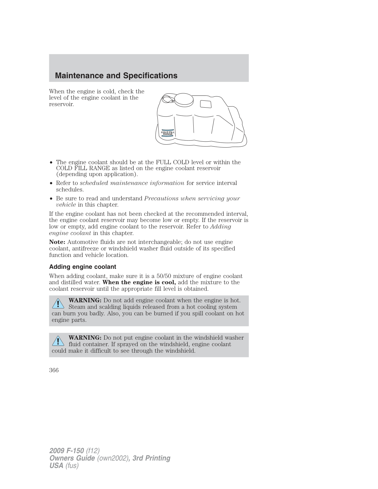
Poor wiper quality can be improved by cleaning the wiper blades and the windshield. Refer to Windows and wiper blades in the Cleaning chapter.
To prolong the life of the wiper blades, it is highly recommended to scrape off the ice on the windshield before turning on the wipers. The layer of ice has many sharp edges and can damage the micro edge of the wiper rubber element.
ENGINE OIL Checking the engine oil
Refer to the scheduled maintenance information for the appropriate intervals for checking the engine oil.
###### To avoid possible oil loss, DO NOT operate the vehicle with the engine oil level dipstick and/or the engine oil filler cap removed.
###### Engine oil and filter recommendations
Look for this certification trademark.
###### Use SAE 5W-20 engine oil
Only use oils “Certified For Gasoline Engines” by the American Petroleum Institute (API). An oil with this trademark symbol conforms to the current engine and emission system protection standards and fuel economy requirements of the International Lubricant Standardization and Approval Committee (ILSAC), comprised of U.S. and Japanese automobile manufacturers.
To protect your engine and engine’s warranty, use Motorcraft SAE 5W-20 or an equivalent SAE 5W-20 oil meeting Ford specification WSS-M2C930-A. SAE 5W-20 oil provides optimum fuel economy and durability performance meeting all requirements for your vehicle’s engine. Refer to Maintenance product specifications and capacities later in this chapter for more information.
Do not use supplemental engine oil additives, cleaners or other engine treatments. They are unnecessary and could lead to engine damage that is not covered by Ford warranty.
Change your engine oil and filter according to the appropriate schedule listed in the scheduled maintenance information.
Ford production and Motorcraft replacement oil filters are designed for added engine protection and long life. If a replacement oil filter is used that does not meet Ford material and design specifications, start-up engine noises or knock may be experienced.
It is recommended you use the appropriate Motorcraft oil filter or another with equivalent performance for your engine application.
###### BATTERY
| | |---|
Your vehicle is equipped with a Motorcraft maintenance-free battery which normally does not require additional water during its life of service.
If your battery has a cover/shield, make sure it is reinstalled after the battery has been cleaned or replaced.
For longer, trouble-free operation, keep the top of the battery clean and dry. Also, make certain the battery cables are always tightly fastened to the battery terminals.
If you see any corrosion on the battery or terminals, remove the cables from the terminals and clean with a wire brush. You can neutralize the acid with a solution of baking soda and water.
It is recommended that the negative battery cable terminal be disconnected from the battery if you plan to store your vehicle for an extended period of time. This will minimize the discharge of your battery during storage.
Note: Electrical or electronic accessories or components added to the vehicle by the dealer or the owner may adversely affect battery performance and durability.
WARNING: Batteries normally produce explosive gases which can cause personal injury. Therefore, do not allow flames, sparks
or lighted substances to come near the battery. When working near the battery, always shield your face and protect your eyes. Always provide proper ventilation.
WARNING: When lifting a plastic-cased battery, excessive pressure on the end walls could cause acid to flow through the
vent caps, resulting in personal injury and/or damage to the vehicle or battery. Lift the battery with a battery carrier or with your hands on opposite corners.
WARNING: Keep batteries out of reach of children. Batteries contain sulfuric acid. Avoid contact with skin, eyes or clothing.
Shield your eyes when working near the battery to protect against possible splashing of acid solution. In case of acid contact with skin or eyes, flush immediately with water for a minimum of 15 minutes and get prompt medical attention. If acid is swallowed, call a physician immediately.
WARNING: Battery posts, terminals and related accessories contain lead and lead compounds. Wash hands after handling.
Battery relearn Because your vehicle’s engine is electronically controlled by a computer, some control conditions are maintained by power from the battery. When the battery is disconnected or a new battery is installed, the engine must relearn its idle and fuel trim strategy for optimum driveability and performance. Flexible fuel vehicles (FFV) must also relearn the ethanol content of the fuel for optimum driveability and performance. To begin this process:
at least one minute.
If the battery has been disconnected or a new battery has been installed, the clock and radio settings must be reset once the battery is reconnected.
• Always dispose of automotive batteries in a responsible manner. Follow your local authorized standards for disposal. Call your local authorized recycling center to find out more about recycling automotive batteries.
RETURN
D
A
E
L
RECYCLE
ENGINE COOLANT Checking engine coolant
The concentration and level of engine coolant should be checked at the intervals listed in scheduled maintenance information. The coolant concentration should be maintained at 50/50 coolant and distilled water, which equates to a freeze point of -34°F (-36°C). Coolant concentration testing is possible with a hydrometer or antifreeze tester. The level of coolant should be maintained at the FULL COLD level or within the COLD FILL RANGE in the coolant reservoir. If the level falls below, add coolant per the instructions in the Adding engine coolant section.
Your vehicle was factory-filled with a 50/50 engine coolant and water concentration. If the concentration of coolant falls below 40% or above 60%, the engine parts could become damaged or not work properly. A 50/50 mixture of coolant and water provides the following:
When the engine is cold, check the level of the engine coolant in the reservoir.
If the engine coolant has not been checked at the recommended interval, the engine coolant reservoir may become low or empty. If the reservoir is low or empty, add engine coolant to the reservoir. Refer to Adding
engine coolant in this chapter. Note: Automotive fluids are not interchangeable; do not use engine coolant, antifreeze or windshield washer fluid outside of its specified function and vehicle location.
###### Adding engine coolant
When adding coolant, make sure it is a 50/50 mixture of engine coolant and distilled water. When the engine is cool, add the mixture to the coolant reservoir until the appropriate fill level is obtained.
WARNING: Do not add engine coolant when the engine is hot. Steam and scalding liquids released from a hot cooling system
can burn you badly. Also, you can be burned if you spill coolant on hot engine parts.
WARNING: Do not put engine coolant in the windshield washer fluid container. If sprayed on the windshield, engine coolant
could make it difficult to see through the windshield.
###### • Add Motorcraft Premium Gold Engine Coolant or equivalent meeting Ford specification WSS-M97B51-A1. Refer to Maintenance product specifications and capacities in this chapter.
Note: Use of Motorcraft Cooling System Stop Leak Pellets or an equivalent product meeting Ford specification WSS-M99B37-B6, may darken the color of Motorcraft Premium Gold Engine Coolant from yellow to golden tan.
For vehicles with overflow coolant systems with a non-pressurized cap on the coolant recovery system, add coolant to the coolant recovery reservoir when the engine is cool. Add the proper mixture of coolant and water to the FULL COLD level. For all other vehicles which have a coolant degas system with a pressurized cap, or if it is necessary to remove the coolant pressure relief cap on the radiator of a vehicle with an overflow system, follow these steps to add engine coolant.
WARNING: To reduce the risk of personal injury, make sure the engine is cool before unscrewing the coolant pressure relief cap.
The cooling system is under pressure; steam and hot liquid can come out forcefully when the cap is loosened slightly.
Add the proper mixture of coolant and water to the cooling system by following these steps:
After any coolant has been added, check the coolant concentration (refer to Checking engine coolant). If the concentration is not 50/50 (protection to –34°F/–36°C), drain some coolant and adjust the concentration. It may take several drains and additions to obtain a 50/50 coolant concentration.
Whenever coolant has been added, the coolant level in the coolant reservoir should be checked the next few times you drive the vehicle. If necessary, add enough 50/50 concentration of engine coolant and distilled water to bring the liquid level to the proper level.
If you have to add more than 1.0 quart (1.0 liter) of engine coolant per month, have your authorized dealer check the engine cooling system. Your cooling system may have a leak. Operating an engine with a low level of coolant can result in engine overheating and possible engine damage.
###### Recycled engine coolant
Ford Motor Company does NOT recommend the use of recycled engine coolant since a Ford-approved recycling process is not yet available.
Used engine coolant should be disposed of in an appropriate manner. Follow your community’s regulations and standards for recycling and disposing of automotive fluids.
###### Coolant refill capacity
To find out how much fluid your vehicle’s cooling system can hold, refer to Maintenance product specifications and capacities in this chapter. Fill your engine coolant reservoir as outlined in Adding engine coolant in this section.
Severe climates If you drive in extremely cold climates (less than –34°F [–36°C]):
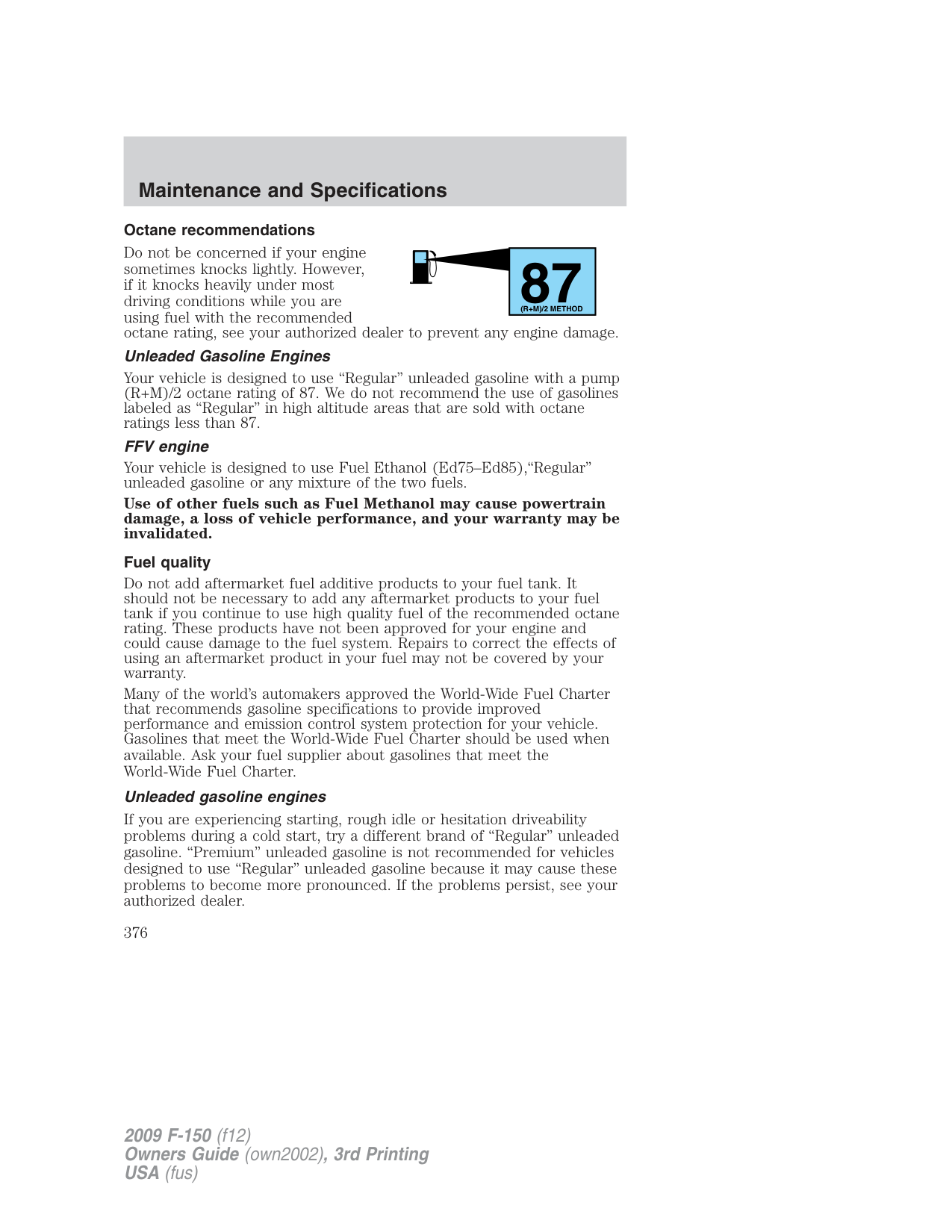
If you drive in extremely hot climates:
Vehicles driven year-round in non-extreme climates should use a 50/50 mixture of engine coolant and distilled water for optimum cooling system and engine protection.
What you should know about fail-safe cooling (if equipped) If the engine coolant supply is depleted, this feature allows the vehicle to be driven temporarily before incremental component damage is incurred. The “fail-safe” distance depends on ambient temperatures, vehicle load and terrain.
How fail-safe cooling works If the engine begins to overheat:
If the engine reaches a preset over-temperature condition, the engine will automatically switch to alternating cylinder operation. Each disabled cylinder acts as an air pump and cools the engine. When this occurs the vehicle will still operate. However:
Once the engine temperature cools, the engine can be re-started. Take your vehicle to an authorized dealer as soon as possible to minimize engine damage.
When fail-safe mode is activated You have limited engine power when in the fail-safe mode, so drive the vehicle with caution. The vehicle will not be able to maintain high speed operation and the engine will run rough. Remember that the engine is capable of completely shutting down automatically to prevent engine damage, therefore:
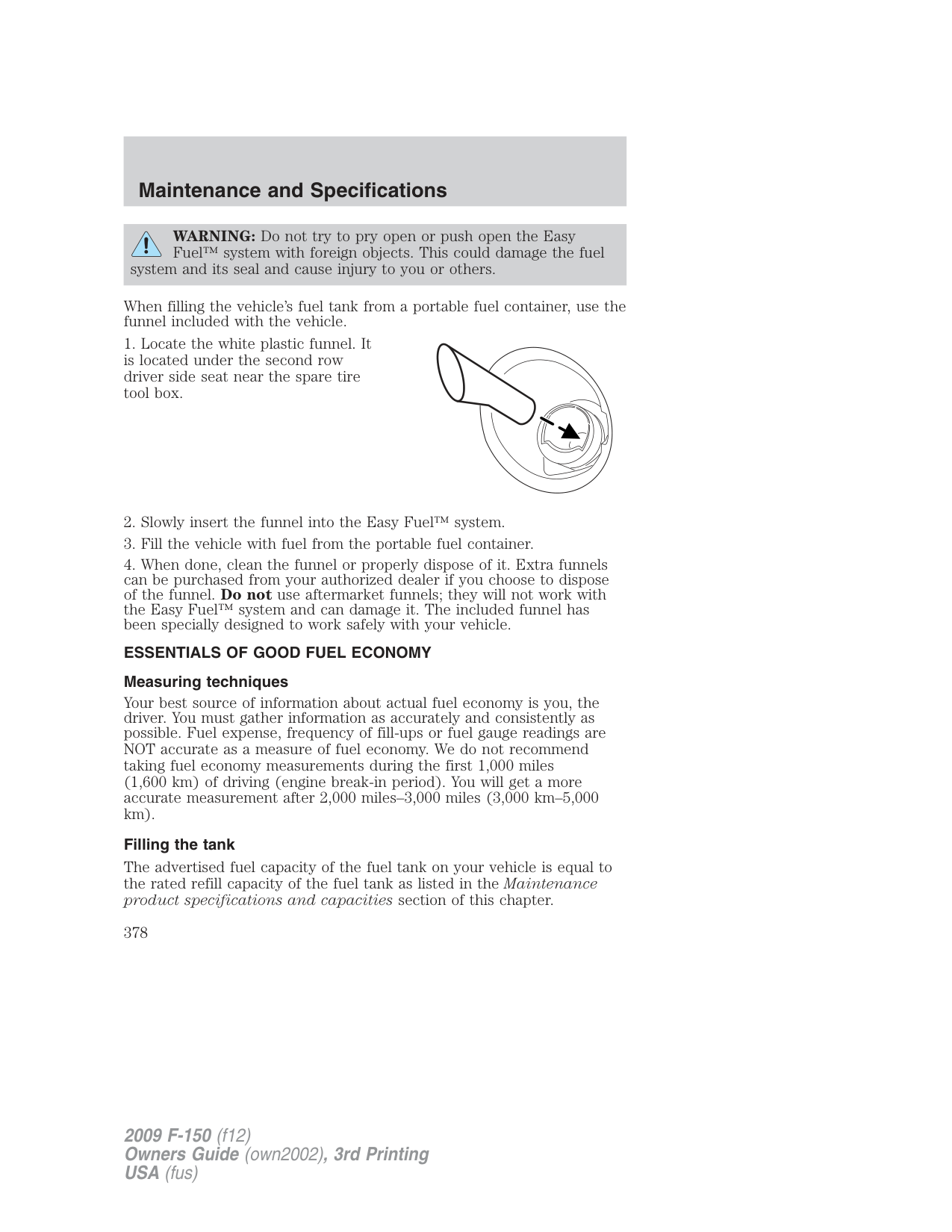
WARNING: Never remove the coolant reservoir cap while the engine is running or hot.
###### FUEL FILTER
Your vehicle is equipped with a lifetime fuel filter that is integrated with the fuel tank. Regular maintenance or replacement is not needed.
WHAT YOU SHOULD KNOW ABOUT AUTOMOTIVE FUELS Important safety precautions
WARNING: Do not overfill the fuel tank. The pressure in an overfilled tank may cause leakage and lead to fuel spray and fire.
WARNING: The fuel system may be under pressure. If you hear a hissing sound near the fuel filler door (Easy Fuel™ “no cap”
fuel system), do not refuel until the sound stops. Otherwise, fuel may spray out, which could cause serious personal injury.
WARNING: Automotive fuels can cause serious injury or death if misused or mishandled.
WARNING: Fuel ethanol and gasoline may contain benzene, which is a cancer-causing agent.
Observe the following guidelines when handling automotive fuel:
Pure ethanol is the alcohol which is the intoxicating agent in liquor, beer and wine. It is distilled from the fermentation of plants such as field corn and sugar cane. When ethanol is produced for use in motor fuels, a small amount of gasoline is added to make it unfit for beverage use. The resulting ethanol blend is called denatured fuel ethanol meaning that it is denatured with 2% to 5% gasoline and is suitable for automotive use.
During the summer season, fuel ethanol may contain a maximum of 85% denatured ethanol (Ed85) and 15% unleaded gasoline. The fuel ethanol has a higher octane rating than unleaded regular or premium gasoline and this allows the design of engines with greater efficiency and power. Winter blends may contain up to 75% denatured ethanol (Ed75) and up to 25% unleaded gasoline to enhance cold engine starts. Severely cold weather may require additional measures for reliable starting.
Ethanol is more chemically active than gasoline. It corrodes some metals and causes some plastic and rubber components to swell, break down or become brittle and crack, especially when mixed with gasoline. Special materials and procedures have been developed for flexible fuel vehicles and the dispensers used by ethanol fuel providers.
WARNING: Flexible fuel components and standard unleaded gasoline fuel components are not interchangeable. If your vehicle
is not serviced in accordance with flexible fuel vehicles procedures, damage may occur and your warranty may be invalidated.
WARNING: When refueling always shut the engine off and never allow sparks or open flames near the filler neck. Never
smoke while refueling. Fuel vapor is extremely hazardous under certain conditions. Care should be taken to avoid inhaling excess fumes.
WARNING: The flow of fuel through a fuel pump nozzle can produce static electricity, which can cause a fire if fuel is
pumped into an ungrounded fuel container. Refueling
WARNING: Fuel vapor burns violently and a fuel fire can cause severe injuries. To help avoid injuries to you and others:
Use the following guidelines to avoid electrostatic charge build-up when filling an ungrounded fuel container:
###### Easy Fuel™ “no cap” fuel system
Your fuel tank is equipped with an Easy Fuel™ “no cap” fuel filler system. This allows you to simply open the fuel filler door and insert the fuel filler nozzle into the fuel system. The Easy Fuel™ system is self-sealing and protected against dust, dirt, water and snow/ice.
When fueling your vehicle:
Note: A fuel spillage concern may occur if overfilling the fuel tank. Do not overfill the tank to the point that the fuel is able to bypass the fuel filler nozzle. The overfilled fuel may run down the drain located below and in front of the fuel filler door.
If the Check Fuel Fill Inlet lamp or Check Fuel Fill Inlet message comes on, the fuel fill inlet may not have properly closed. The inlet may have stuck open or debris may be preventing the inlet from fully closing. At the next opportunity, safely pull off the road, turn off the engine, open the fuel filler door and remove any visible debris from the fuel fill opening. Insert either the fuel fill nozzle or the fuel fill funnel (see Refilling with a portable fuel container for funnel location) provided with the vehicle several times to dislodge any debris and/or allow the inlet to close properly. If this action corrects the problem, the Check Fuel Fill Inlet lamp or Check Fuel Fill Inlet message may not reset immediately. It may take several driving cycles for the Check Fuel Fill Inlet lamp or Check Fuel Fill Inlet message to turn off. A driving cycle consists of an engine start-up (after four or more hours with the engine off) followed by city/highway driving. Continuing to drive with the Check Fuel Fill Inlet lamp or Check Fuel Fill Inlet message on may cause the Service Engine Soon lamp to turn on as well.
WARNING: The fuel system may be under pressure. If you hear a hissing sound near the fuel filler door (Easy Fuel™ “no cap”
fuel system), do not refuel until the sound stops. Otherwise, fuel may spray out, which could cause serious personal injury.
Flex Fuel Vehicle (FFV) fuel fill inlet Flex fuel vehicles have a yellow bezel placed over the fuel fill inlet.
###### Choosing the right fuel
If your vehicle is a flexible fuel vehicle (FFV), use only UNLEADED FUEL and FUEL ETHANOL (Ed75–Ed85).
If your vehicle is not a flexible fuel vehicle (FFV), then only use UNLEADED fuel or UNLEADED fuel blended with a maximum of 10% ethanol. Do not use fuel ethanol (E85), diesel, methanol, leaded fuel or any other fuel.
The use of leaded fuel is prohibited by law and could damage your vehicle.
Your vehicle was not designed to use fuel or fuel additives with metallic compounds, including manganese-based additives.
Note: Use of any fuel other than those recommended may cause powertrain damage, a loss of vehicle performance, and repairs may not be covered under warranty.
###### Cleaner air
Ford endorses the use of reformulated “cleaner-burning” gasolines to improve air quality, per the recommendations in the Choosing the right fuel section.
###### Octane recommendations
Do not be concerned if your engine sometimes knocks lightly. However, if it knocks heavily under most driving conditions while you are using fuel with the recommended octane rating, see your authorized dealer to prevent any engine damage.
|87
(R+M)/2 METHOD| |---|
###### Unleaded Gasoline Engines
Your vehicle is designed to use “Regular” unleaded gasoline with a pump (R+M)/2 octane rating of 87. We do not recommend the use of gasolines labeled as “Regular” in high altitude areas that are sold with octane ratings less than 87.
###### FFV engine
Your vehicle is designed to use Fuel Ethanol (Ed75–Ed85),“Regular” unleaded gasoline or any mixture of the two fuels.
Use of other fuels such as Fuel Methanol may cause powertrain damage, a loss of vehicle performance, and your warranty may be invalidated. Fuel quality Do not add aftermarket fuel additive products to your fuel tank. It should not be necessary to add any aftermarket products to your fuel tank if you continue to use high quality fuel of the recommended octane rating. These products have not been approved for your engine and could cause damage to the fuel system. Repairs to correct the effects of using an aftermarket product in your fuel may not be covered by your warranty. Many of the world’s automakers approved the World-Wide Fuel Charter that recommends gasoline specifications to provide improved performance and emission control system protection for your vehicle. Gasolines that meet the World-Wide Fuel Charter should be used when available. Ask your fuel supplier about gasolines that meet the World-Wide Fuel Charter. Unleaded gasoline engines
If you are experiencing starting, rough idle or hesitation driveability problems during a cold start, try a different brand of “Regular” unleaded gasoline. “Premium” unleaded gasoline is not recommended for vehicles designed to use “Regular” unleaded gasoline because it may cause these problems to become more pronounced. If the problems persist, see your authorized dealer.
FFV engine Flex fuel vehicles have a yellow bezel around the fuel fill inlet. It is best not to alternate repeatedly between gasoline and E85. If you do switch fuels, it is recommended that you add as much fuel as possible—at least half a tank. Do not add less than five gallons (18.9L) when refueling. You should drive the vehicle immediately after refueling for at least 5 miles (8 km) to allow the vehicle to adapt to the change in ethanol concentration. If you operate your vehicle 50% or more of the time on ethanol, you should follow a different maintenance schedule. In addition to this, it is also recommended to fill the fuel tank with regular unleaded gasoline once every 3,000 miles (4,800 km). See scheduled maintenance information for more information. Running out of fuel
Avoid running out of fuel because this situation may have an adverse effect on powertrain components.
If you have run out of fuel:
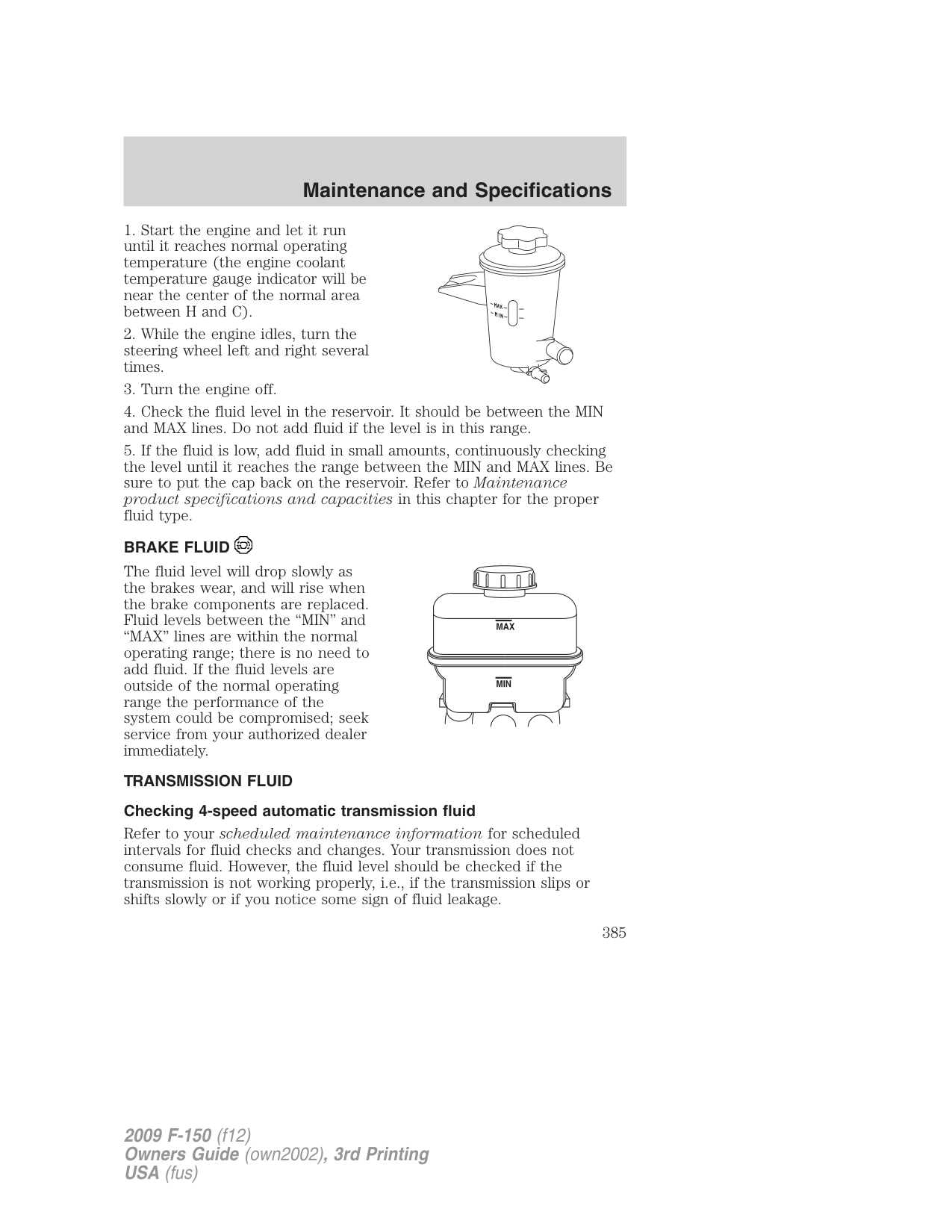
###### Refilling with a portable fuel container
With the Easy Fuel™ “no cap” fuel system, use the following directions when filling from a portable fuel container:
WARNING: Do not insert the nozzle of portable fuel containers or aftermarket funnels into the Easy Fuel™ system. This could
damage the fuel system and its seal, and may cause fuel to run onto the ground instead of filling the tank, which could result in serious personal injury.
WARNING: Do not try to pry open or push open the Easy Fuel™ system with foreign objects. This could damage the fuel
system and its seal and cause injury to you or others.
When filling the vehicle’s fuel tank from a portable fuel container, use the funnel included with the vehicle.
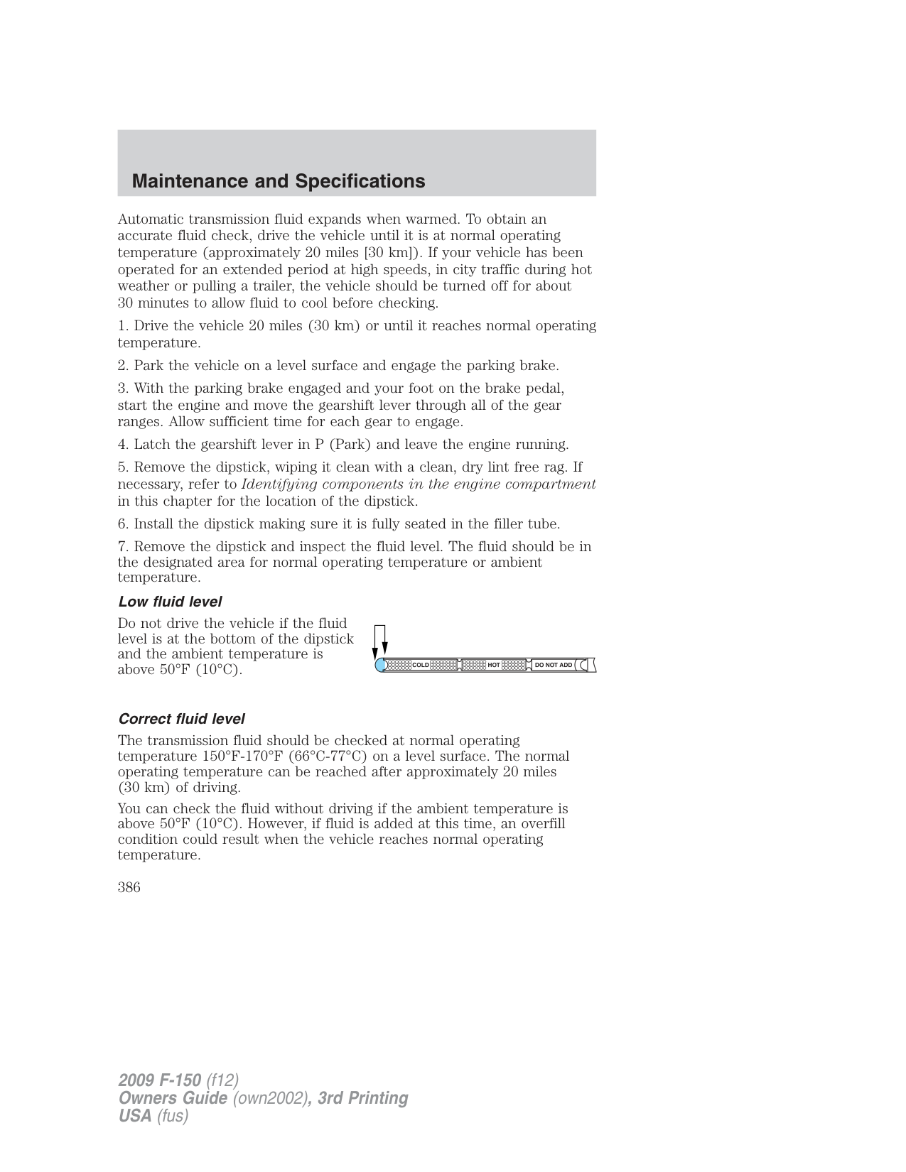
Measuring techniques Your best source of information about actual fuel economy is you, the driver. You must gather information as accurately and consistently as possible. Fuel expense, frequency of fill-ups or fuel gauge readings are NOT accurate as a measure of fuel economy. We do not recommend taking fuel economy measurements during the first 1,000 miles (1,600 km) of driving (engine break-in period). You will get a more accurate measurement after 2,000 miles–3,000 miles (3,000 km–5,000 km).
###### Filling the tank
The advertised fuel capacity of the fuel tank on your vehicle is equal to the rated refill capacity of the fuel tank as listed in the Maintenance product specifications and capacities section of this chapter.
The advertised capacity is the amount of the indicated capacity and the empty reserve combined. Indicated capacity is the difference in the amount of fuel in a full tank and a tank when the fuel gauge indicates empty. Empty reserve is the small amount of fuel remaining in the fuel tank after the fuel gauge indicates empty.
The amount of usable fuel in the empty reserve varies and should not be relied upon to increase driving range. When refueling your vehicle after the fuel gauge indicates empty, you might not be able to refuel the full amount of the advertised capacity of the fuel tank due to the empty reserve still present in the tank.
For consistent results when filling the fuel tank:
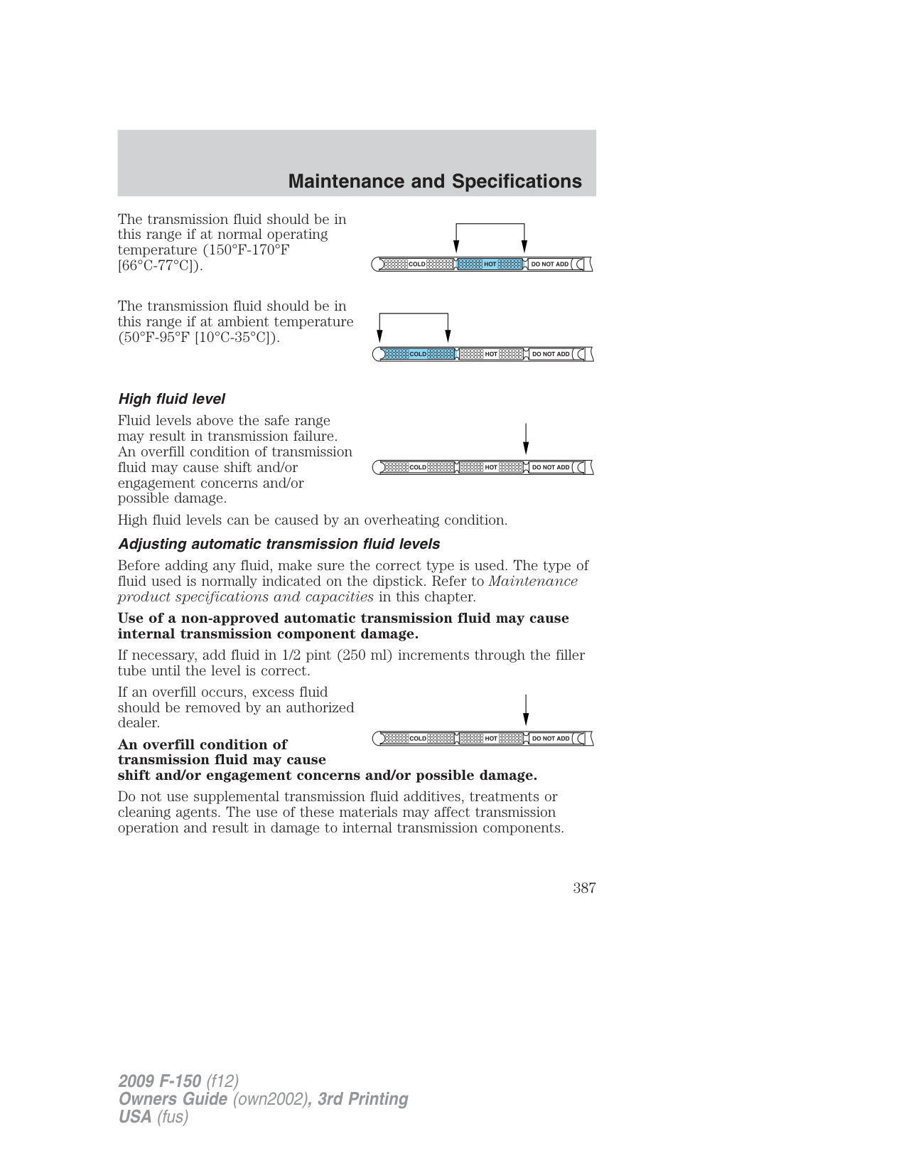
Keep a record for at least one month and record the type of driving (city or highway). This will provide an accurate estimate of the vehicle’s fuel economy under current driving conditions. Additionally, keeping records during summer and winter will show how temperature impacts fuel economy. In general, lower temperatures give lower fuel economy.
###### Driving style — good driving and fuel economy habits
Give consideration to the lists that follow and you may be able to change a number of variables and improve your fuel economy.
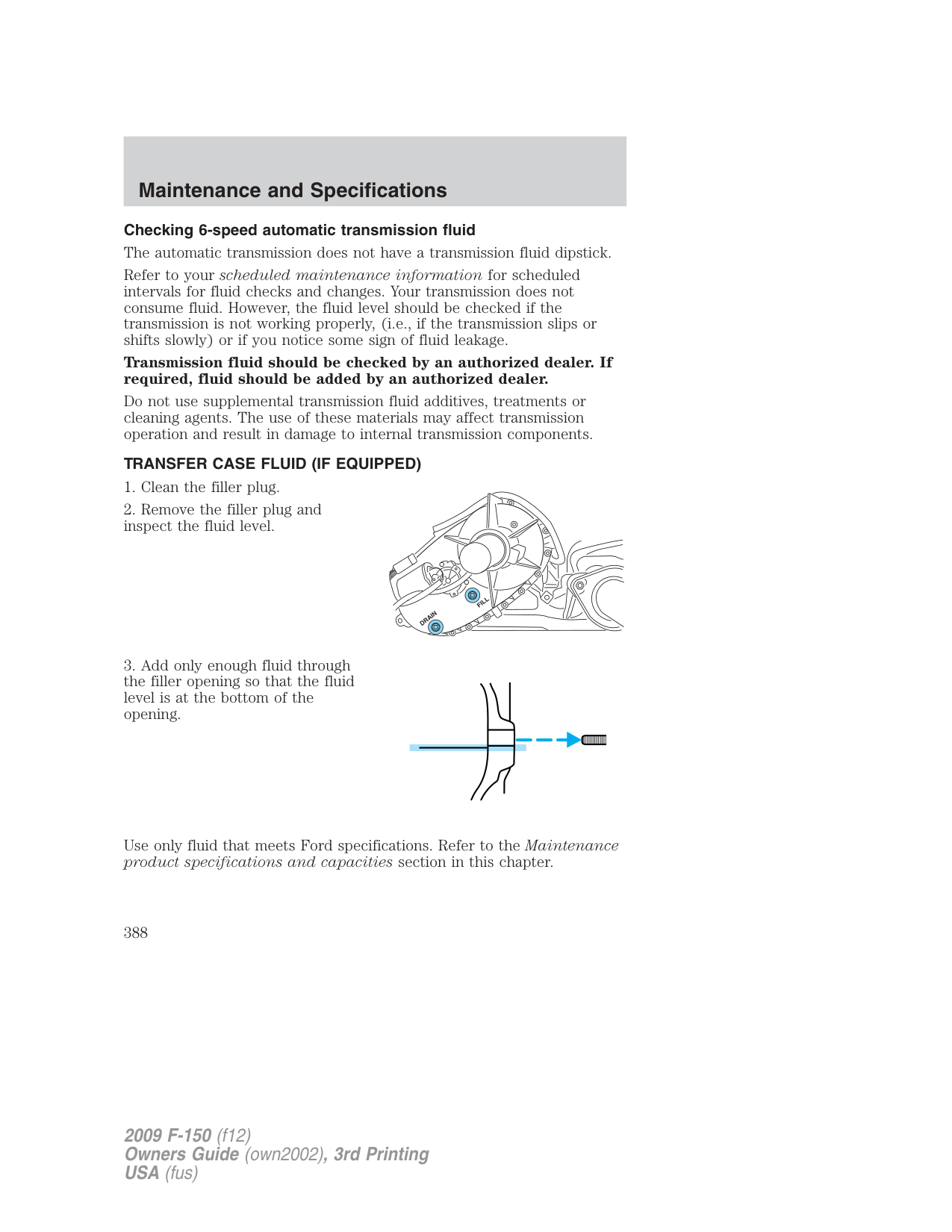
###### Habits
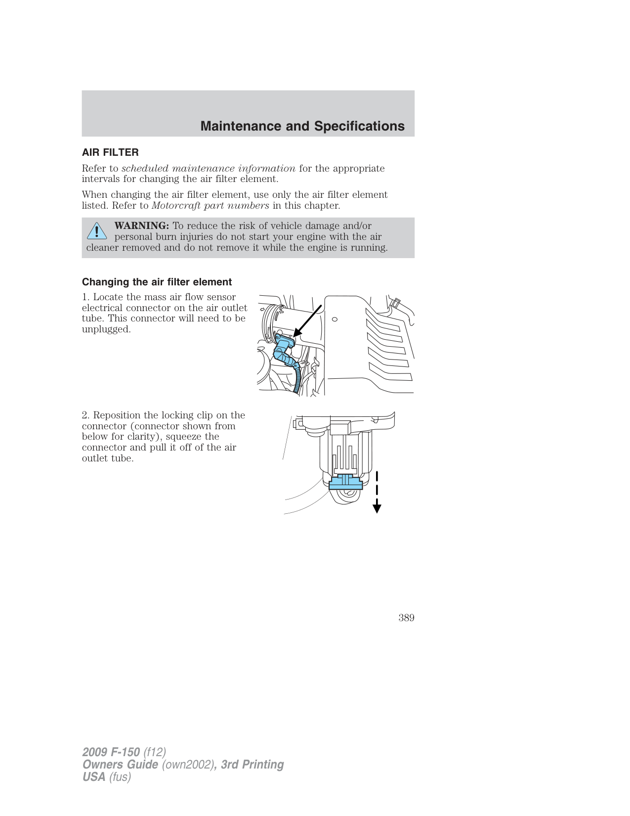
###### Conditions
###### EPA fuel economy estimates
Every new vehicle should have a window sticker containing EPA fuel economy estimates. Contact your authorized dealer if the window sticker is not supplied with your vehicle. The EPA fuel economy estimates should be your guide for the fuel economy comparisons with other vehicles. Your fuel economy may vary depending upon the method of operation and conditions.
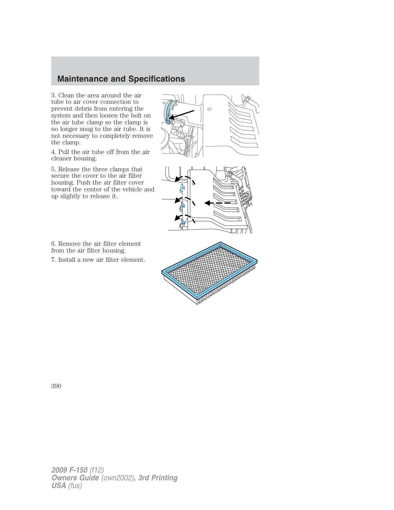
###### EMISSION CONTROL SYSTEM
Your vehicle is equipped with various emission control components and a catalytic converter which will enable your vehicle to comply with applicable exhaust emission standards. To make sure that the catalytic converter and other emission control components continue to work properly:
The scheduled maintenance items listed in scheduled maintenance information are essential to the life and performance of your vehicle and to its emissions system. If other than Ford, Motorcraft or Ford-authorized parts are used for maintenance replacements or for service of components affecting emission control, such non-Ford parts should be equivalent to genuine Ford Motor Company parts in performance and durability.
WARNING: Do not park, idle, or drive your vehicle in dry grass or other dry ground cover. The emission system heats up the
engine compartment and exhaust system, which can start a fire.
Illumination of the service engine soon indicator, charging system warning light or the temperature warning light, fluid leaks, strange odors, smoke or loss of engine power could indicate that the emission control system is not working properly. An improperly operating or damaged exhaust system may allow exhaust to enter the vehicle. Have a damaged or improperly operating exhaust system inspected and repaired immediately.
WARNING: Exhaust leaks may result in entry of harmful and potentially lethal fumes into the passenger compartment.
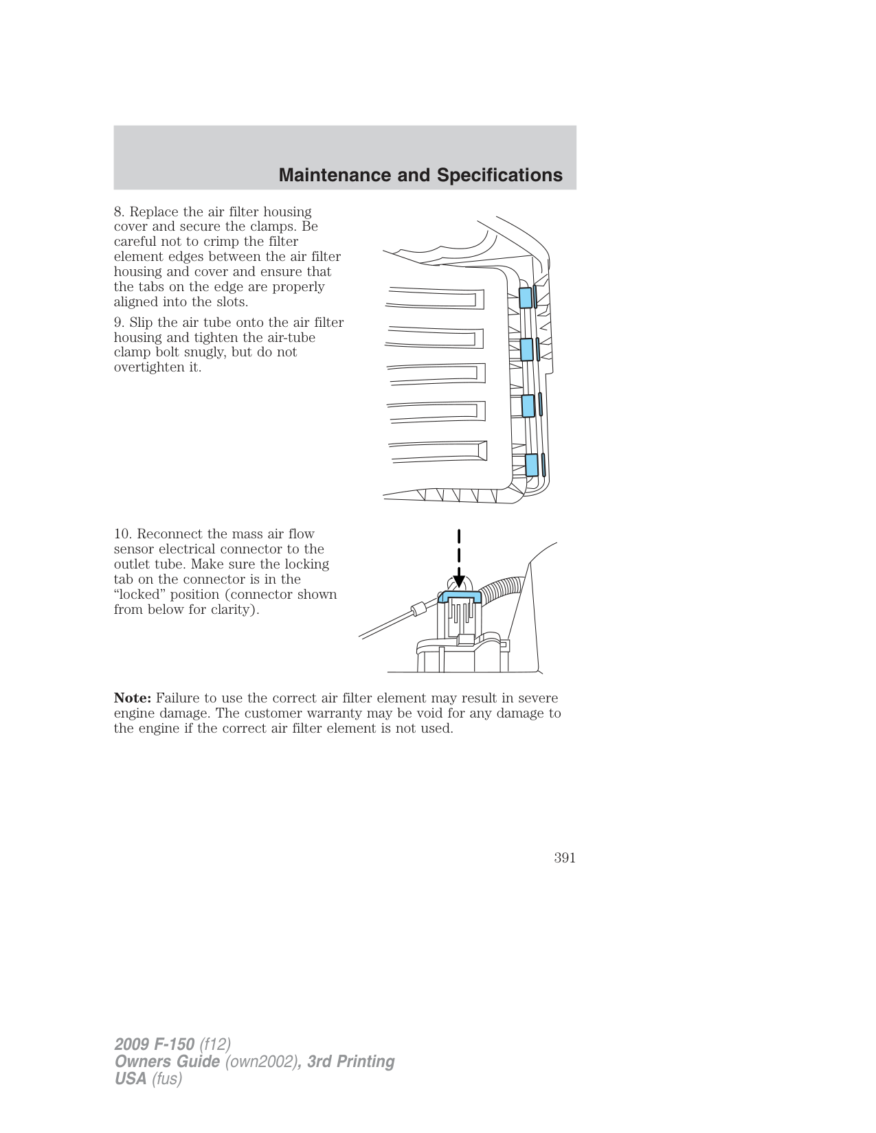
Do not make any unauthorized changes to your vehicle or engine. By law, vehicle owners and anyone who manufactures, repairs, services, sells, leases, trades vehicles, or supervises a fleet of vehicles are not permitted to intentionally remove an emission control device or prevent
it from working. Information about your vehicle’s emission system is on the Vehicle Emission Control Information Decal located on or near the engine. This decal also lists engine displacement.
Please consult your Warranty Guide/Customer Information Guide for complete emission warranty information.
On board diagnostics (OBD-II) Your vehicle is equipped with a computer that monitors the engine’s emission control system. This system is commonly known as the On Board Diagnostics System (OBD-II). The OBD-II system protects the environment by ensuring that your vehicle continues to meet government emission standards. The OBD-II system also assists your authorized dealer in properly servicing your vehicle. When the service engine soon indicator illuminates, the OBD-II system has detected a malfunction. Temporary malfunctions may cause the service engine soon indicator to illuminate. Examples are:
These temporary malfunctions can be corrected by filling the fuel tank with good quality fuel, properly closing the fuel fill inlet or letting the electrical system dry out. After three driving cycles without these or any other temporary malfunctions present, the service engine soon
indicator should stay off the next time the engine is started. A driving cycle consists of a cold engine startup followed by mixed city/highway driving. No additional vehicle service is required.
If the service engine soon indicator remains on, have your vehicle serviced at the first available opportunity. Although some malfunctions detected by the OBD-II may not have symptoms that are apparent, continued driving with the service engine soon indicator on can result in increased emissions, lower fuel economy, reduced engine and transmission smoothness, and lead to more costly repairs.
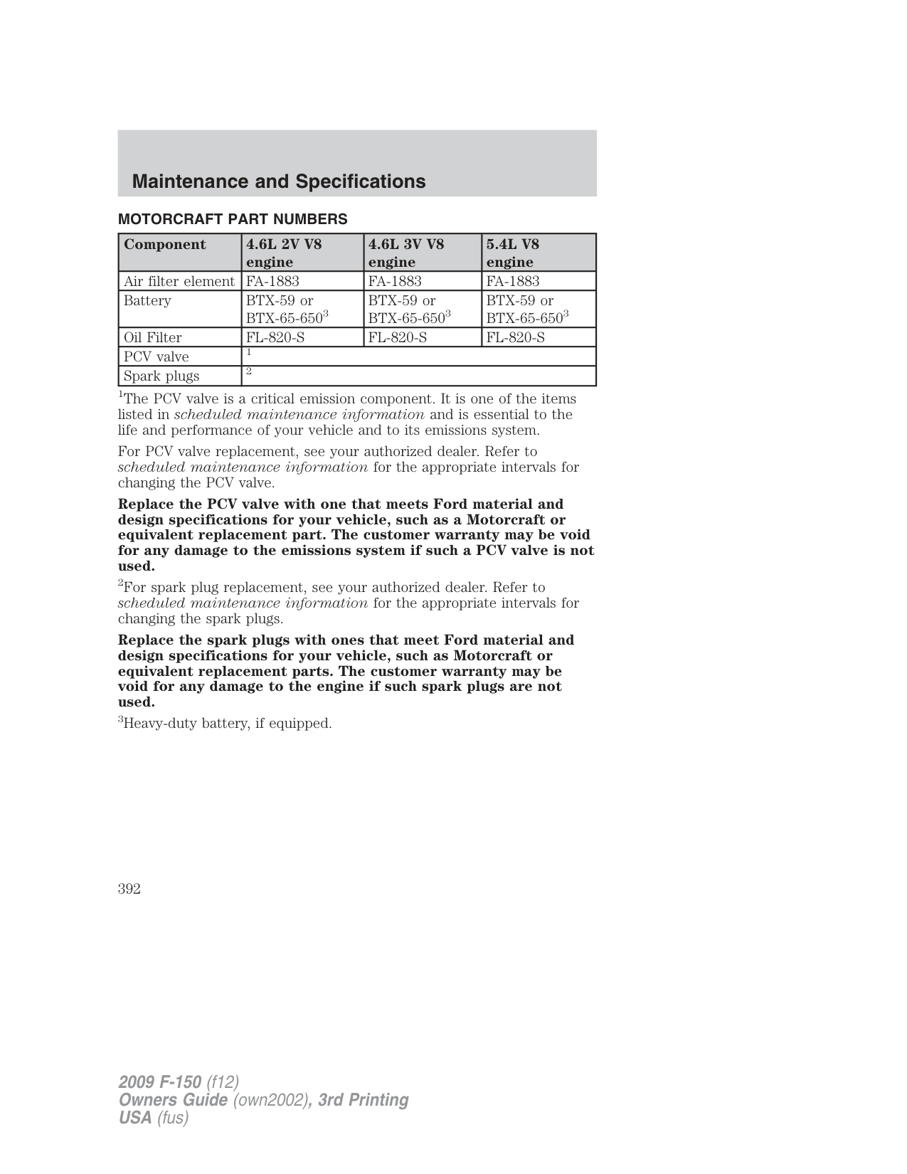
Readiness for Inspection/Maintenance (I/M) testing Some state/provincial and local governments may have Inspection/Maintenance (I/M) programs to inspect the emission control equipment on your vehicle. Failure to pass this inspection could prevent you from getting a vehicle registration. Your vehicle may not pass the I/M test if the service engine soon indicator is on or not working properly (bulb is burned out), or if the OBD-II system has determined that some of the emission control systems have not been properly checked. In this case, the vehicle is considered not ready for I/M testing.
If the service engine soon indicator is on or the bulb does not work, the vehicle may need to be serviced. Refer to the On board diagnostics (OBD-II) description in this chapter. If the vehicle’s engine or transmission has just been serviced, or the battery has recently run down or been replaced, the OBD-II system may indicate that the vehicle is not ready for I/M testing. To determine if the vehicle is ready for I/M testing, turn the ignition key to the on position for 15 seconds without cranking the engine. If the service engine soon indicator blinks eight times, it means that the vehicle is not ready for I/M testing; if the service engine soon indicator stays on solid, it means that the vehicle is ready for I/M testing. The OBD-II system is designed to check the emission control system during normal driving. A complete check may take several days. If the vehicle is not ready for I/M testing, the following driving cycle consisting of mixed city and highway driving may be performed:
Allow the vehicle to sit for at least eight hours without starting the engine. Then, start the engine and complete the above driving cycle. The engine must warm up to its normal operating temperature. Once started, do not turn off the engine until the above driving cycle is complete. If the vehicle is still not ready for I/M testing, the above driving cycle will have to be repeated.
POWER STEERING FLUID Check the power steering fluid. Refer to scheduled maintenance information.

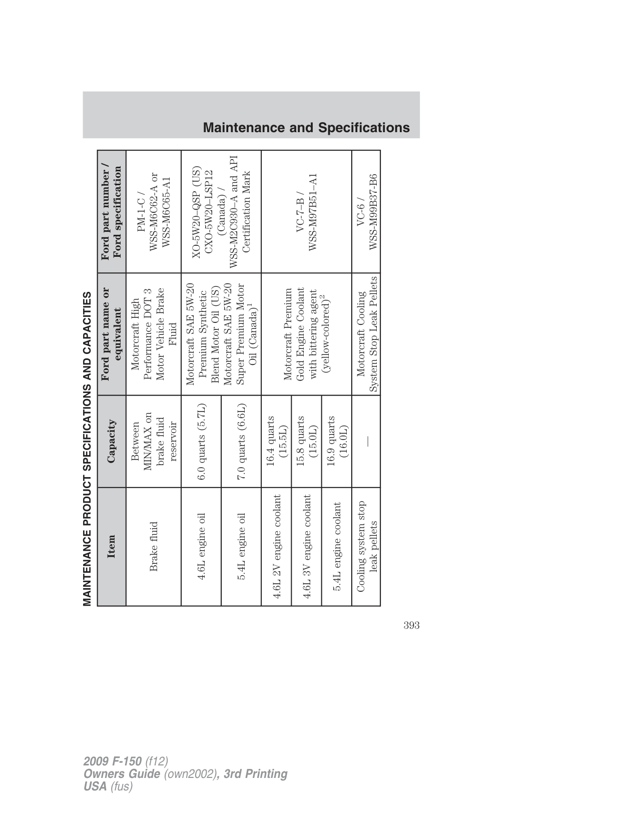
###### BRAKE FLUID


The fluid level will drop slowly as the brakes wear, and will rise when the brake components are replaced. Fluid levels between the “MIN” and “MAX” lines are within the normal operating range; there is no need to add fluid. If the fluid levels are outside of the normal operating range the performance of the system could be compromised; seek service from your authorized dealer immediately.
TRANSMISSION FLUID Checking 4-speed automatic transmission fluid
Refer to your scheduled maintenance information for scheduled intervals for fluid checks and changes. Your transmission does not consume fluid. However, the fluid level should be checked if the transmission is not working properly, i.e., if the transmission slips or shifts slowly or if you notice some sign of fluid leakage.
Automatic transmission fluid expands when warmed. To obtain an accurate fluid check, drive the vehicle until it is at normal operating temperature (approximately 20 miles [30 km]). If your vehicle has been operated for an extended period at high speeds, in city traffic during hot weather or pulling a trailer, the vehicle should be turned off for about 30 minutes to allow fluid to cool before checking.
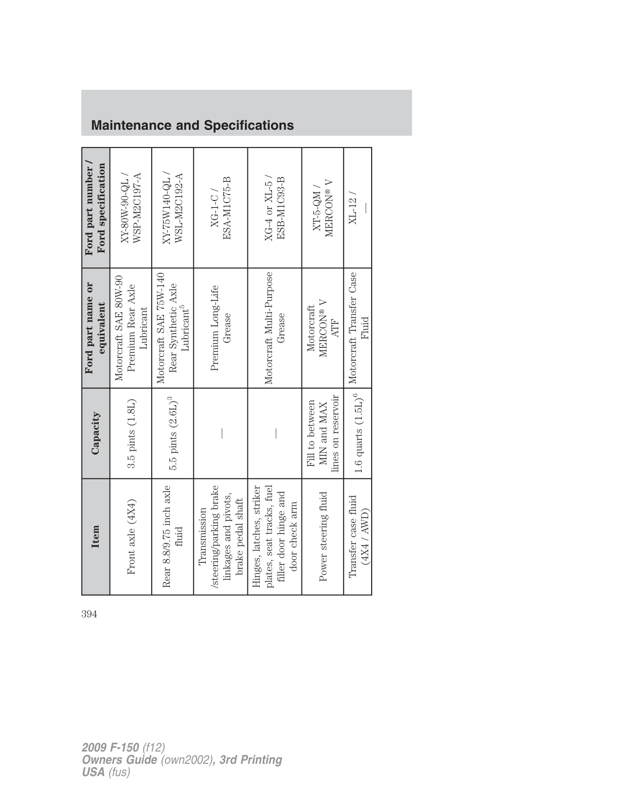
Do not drive the vehicle if the fluid level is at the bottom of the dipstick and the ambient temperature is above 50°F (10°C).
###### Correct fluid level
The transmission fluid should be checked at normal operating temperature 150°F-170°F (66°C-77°C) on a level surface. The normal operating temperature can be reached after approximately 20 miles (30 km) of driving.
You can check the fluid without driving if the ambient temperature is above 50°F (10°C). However, if fluid is added at this time, an overfill condition could result when the vehicle reaches normal operating temperature.
The transmission fluid should be in this range if at normal operating temperature (150°F-170°F [66°C-77°C]).

The transmission fluid should be in this range if at ambient temperature (50°F-95°F [10°C-35°C]).
###### High fluid level
Fluid levels above the safe range may result in transmission failure. An overfill condition of transmission fluid may cause shift and/or engagement concerns and/or possible damage.
High fluid levels can be caused by an overheating condition. Adjusting automatic transmission fluid levels
Before adding any fluid, make sure the correct type is used. The type of fluid used is normally indicated on the dipstick. Refer to Maintenance product specifications and capacities in this chapter.
Use of a non-approved automatic transmission fluid may cause internal transmission component damage.
If necessary, add fluid in 1/2 pint (250 ml) increments through the filler tube until the level is correct.
If an overfill occurs, excess fluid should be removed by an authorized dealer.
An overfill condition of transmission fluid may cause shift and/or engagement concerns and/or possible damage.
Do not use supplemental transmission fluid additives, treatments or cleaning agents. The use of these materials may affect transmission operation and result in damage to internal transmission components.
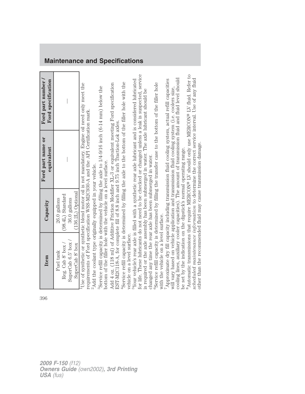
Checking 6-speed automatic transmission fluid The automatic transmission does not have a transmission fluid dipstick. Refer to your scheduled maintenance information for scheduled intervals for fluid checks and changes. Your transmission does not consume fluid. However, the fluid level should be checked if the transmission is not working properly, (i.e., if the transmission slips or shifts slowly) or if you notice some sign of fluid leakage.
Transmission fluid should be checked by an authorized dealer. If required, fluid should be added by an authorized dealer.
Do not use supplemental transmission fluid additives, treatments or cleaning agents. The use of these materials may affect transmission operation and result in damage to internal transmission components.
###### TRANSFER CASE FLUID (IF EQUIPPED)
FILL
IN
DRA
Use only fluid that meets Ford specifications. Refer to the Maintenance product specifications and capacities section in this chapter.
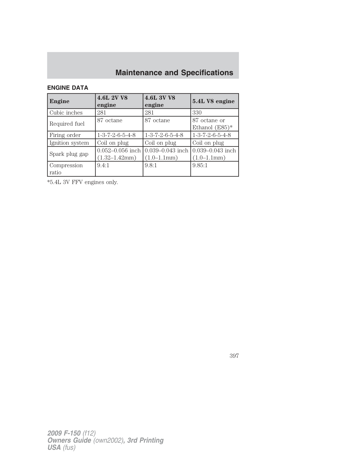
###### AIR FILTER
Refer to scheduled maintenance information for the appropriate intervals for changing the air filter element.
When changing the air filter element, use only the air filter element listed. Refer to Motorcraft part numbers in this chapter.
WARNING: To reduce the risk of vehicle damage and/or personal burn injuries do not start your engine with the air
cleaner removed and do not remove it while the engine is running.
###### Changing the air filter element
| | | |---|---| | | |
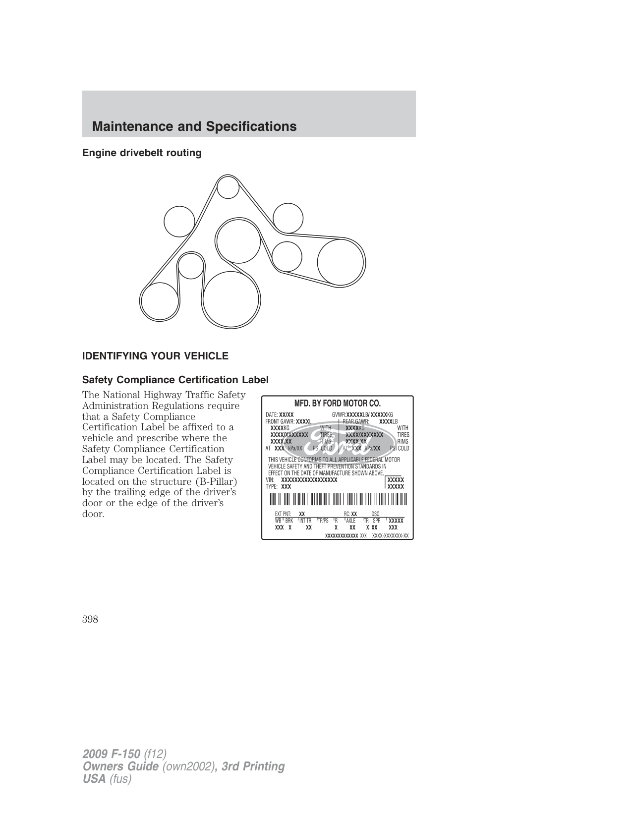
Note: Failure to use the correct air filter element may result in severe engine damage. The customer warranty may be void for any damage to the engine if the correct air filter element is not used.
###### MOTORCRAFT PART NUMBERS
|Component|4.6L 2V V8 engine|4.6L 3V V8 engine|5.4L V8 engine| |---|---|---|---|
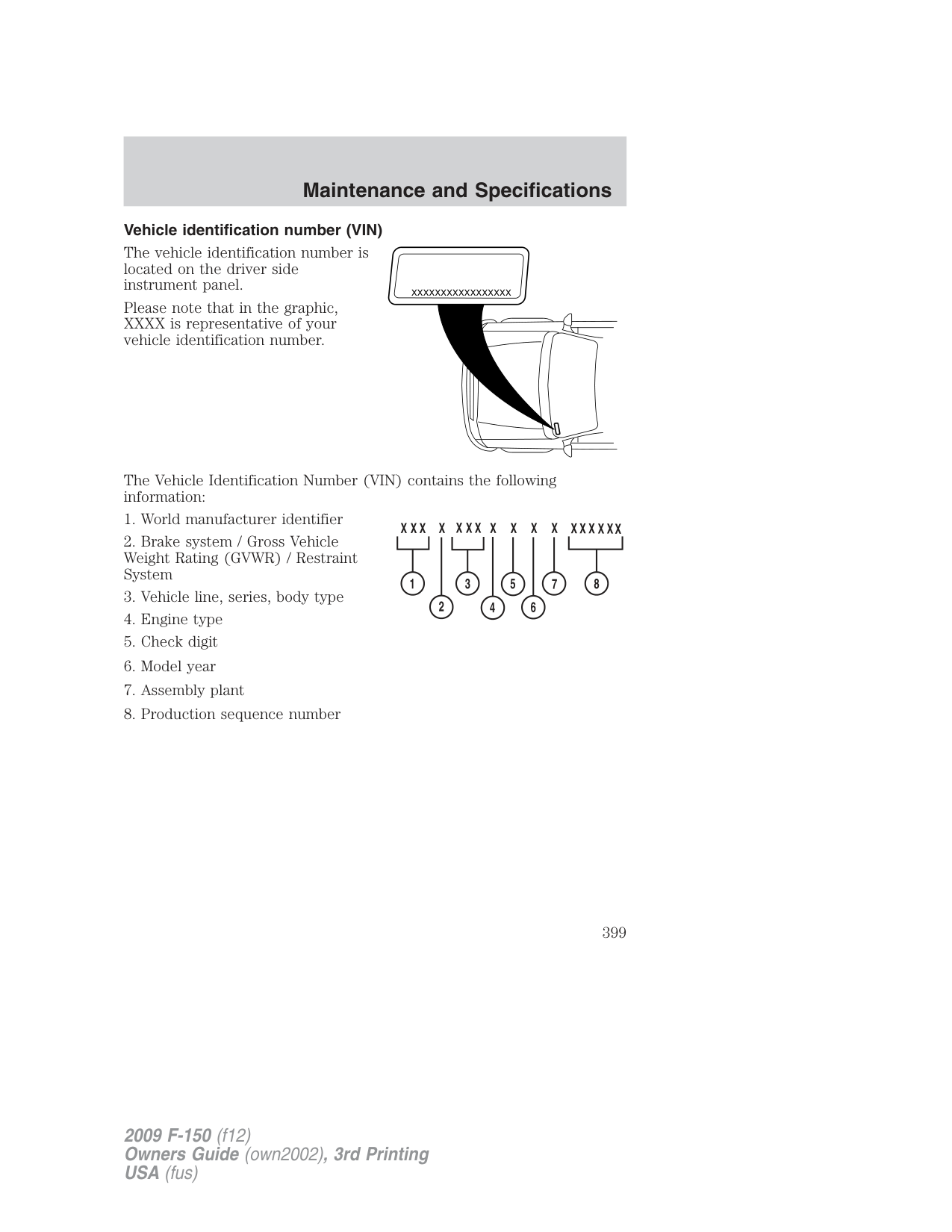
|Air filter element|FA-1883|FA-1883|FA-1883| |Battery|BTX-59 or BTX-65-6503|BTX-59 or BTX-65-6503|BTX-59 or BTX-65-6503| |Oil Filter|FL-820-S|FL-820-S|FL-820-S| |PCV valve|1|1|1| |Spark plugs|2|2|2|
1The PCV valve is a critical emission component. It is one of the items listed in scheduled maintenance information and is essential to the life and performance of your vehicle and to its emissions system. For PCV valve replacement, see your authorized dealer. Refer to scheduled maintenance information for the appropriate intervals for changing the PCV valve.
Replace the PCV valve with one that meets Ford material and design specifications for your vehicle, such as a Motorcraft or equivalent replacement part. The customer warranty may be void for any damage to the emissions system if such a PCV valve is not used.
2For spark plug replacement, see your authorized dealer. Refer to scheduled maintenance information for the appropriate intervals for changing the spark plugs.
Replace the spark plugs with ones that meet Ford material and design specifications for your vehicle, such as Motorcraft or equivalent replacement parts. The customer warranty may be void for any damage to the engine if such spark plugs are not used.
|Ford part number /
Ford specification|PM-1-C /
WSS-M6C62-A or
WSS-M6C65-A1|XO-5W20–QSP (US)
CXO-5W20–LSP12
(Canada) /
WSS-M2C930–A and API
Certification Mark|XO-5W20–QSP (US)
CXO-5W20–LSP12
(Canada) /
WSS-M2C930–A and API
Certification Mark|VC-7–B /
WSS-M97B51–A1|VC-7–B /
WSS-M97B51–A1|VC-7–B /
WSS-M97B51–A1|VC-6 /
WSS-M99B37-B6| |---|---|---|---|---|---|---|---|
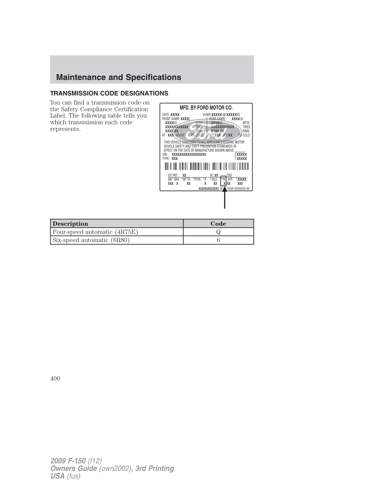
|Ford part name or
equivalent|Motorcraft High
Performance DOT 3
Motor Vehicle Brake
Fluid|Motorcraft SAE 5W-20
Premium Synthetic
Blend Motor Oil (US)
Motorcraft SAE 5W-20
Super Premium Motor
Oil (Canada)1|Motorcraft SAE 5W-20
Premium Synthetic
Blend Motor Oil (US)
Motorcraft SAE 5W-20
Super Premium Motor
Oil (Canada)1|Motorcraft Premium
Gold Engine Coolant
with bittering agent
(yellow-colored)2|Motorcraft Premium
Gold Engine Coolant
with bittering agent
(yellow-colored)2|Motorcraft Premium
Gold Engine Coolant
with bittering agent
(yellow-colored)2|Motorcraft Cooling
System Stop Leak Pellets| | |Between
MIN/MAX on
brake fluid
reservoir| | |16.4 quarts
(15.5L)|15.8 quarts
(15.0L)|16.9 quarts
(16.0L)|—| |Item Capacity|Brake fluid|4.6L engine oil 6.0 quarts (5.7L)|5.4L engine oil 7.0 quarts (6.6L)|4.6L 2V engine coolant|4.6L 3V engine coolant|5.4L engine coolant|Cooling system stop
leak pellets|
###### MAINTENANCE PRODUCT SPECIFICATIONS AND CAPACITIES
|Ford part number /
Ford specification|XY-80W-90-QL /
WSP-M2C197-A|XY-75W140-QL /
WSL-M2C192-A|XG-1-C /
ESA-M1C75-B|XG-4 or XL-5 /
ESB-M1C93-B|XT-5-QM /
MERCONV|XL-12 /
—| |---|---|---|---|---|---|---| |Ford part name or
equivalent|Motorcraft SAE 80W-90
Premium Rear Axle
Lubricant|Motorcraft SAE 75W-140
Rear Synthetic Axle
Lubricant5|Premium Long-Life
Grease|Motorcraft Multi-Purpose
Grease|Motorcraft
MERCONV
ATF|Motorcraft Transfer Case
Fluid| | | |5.5 pints (2.6L)3|—|—|Fill to between
MIN and MAX
lines on reservoir|1.6 quarts (1.5L)6| |Item Capacity|Front axle (4X4) 3.5 pints (1.8L)|Rear 8.8/9.75 inch axle
fluid|Transmission
/steering/parking brake
linkages and pivots,
brake pedal shaft|Hinges, latches, striker
plates, seat tracks, fuel
filler door hinge and
door check arm|Power steering fluid|Transfer case fluid
(4X4 / AWD)|
|Ford part number /
Ford specification|XT-10-QLV /
MERCONLV|XT-10-QLV /
MERCONLV|ZC-32-A /
WSB-M8B16-A2|——|——|——| |---|---|---|---|---|---|---| |Ford part name or
equivalent|Motorcraft
MERCONLV
ATF8|Motorcraft
MERCONLV
ATF8|Motorcraft Premium
Windshield Washer
Concentrate| | | | | |13.9 quarts
(13.2L)7|13.9 quarts
(13.2L)7| |26.0 gallons
(98.4L)|26.0 gallons
(98.4L) Standard
36.0 gallons
(136.2L) Optional|26.0 gallons
(98.4L) Standard
36.0 gallons
(136.2L) Optional| |Item Capacity|Automatic transmission
fluid (4R75E)|Automatic transmission
fluid (6R80)|Windshield washer fluid 4.25 quarts (4.0L)|Fuel tank
Reg. Cab 6.5’ box /
SuperCab 5.5’ box|Fuel tank Crew Cab 5.5’
box|Fuel tank Crew Cab 6.5’
box|
|Ford part number /
Ford specification|——| |---|---| |Ford part name or
equivalent| | | |26.0 gallons
(98.4L) Standard
36.0 gallons
(136.2L) Optional| |Item Capacity|Fuel tank
Reg. Cab 8’ box /
SuperCab 6.5’ box /
SuperCab 8’ box|
for life. These lubricants do not need to be checked or changed unless a leak is suspected, service
8Automatic transmissions that require MERCONLV should only use MERCONLV fluid. Refer to
cooling lines, auxiliary cooler capacities). The amount of transmission fluid and fluid level should
scheduled maintenance informationto determine the correct service interval. Use of any fluid
5Your vehicle’s rear axle is filled with a synthetic rear axle lubricant and is considered lubricated
7Approximate dry fill capacity including transmission fluid cooling system, actual refill capacities
4Service refill capacity is determined by filling the axle to the bottom of the filler hole with the
6Service refill capacity is determined by filling the transfer case to the bottom of the filler hole
Add 4 oz. (118 ml) of Additive Friction Modifier XL-3 or equivalent meeting Ford specification
1Use of synthetic or synthetic blend motor oil is not mandatory. Engine oil need only meet the
will vary based on vehicle application and transmission fluid cooling system (i.e. coolers size,
is required or the axle assembly has been submerged in water. The axle lubricant should be
requirements of Ford specification WSS-M2C930-A and the API Certification mark.
EST-M2C118-A, for complete fill of 8.8 inch and 9.75 inch Traction-Lok axles.
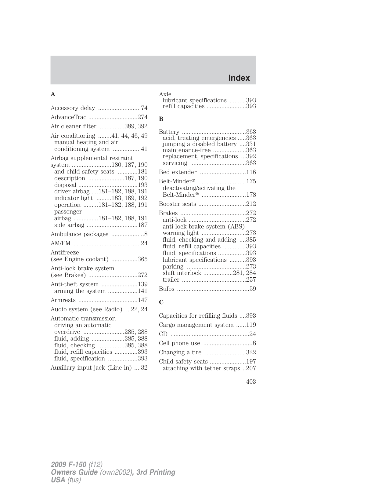
other than the recommended fluid may cause transmission damage.
be set by the indication on the dipstick’s normal operating range.
changed any time the rear axle has been submerged in water.
bottom of the filler hole with the vehicle on a level surface.
with the vehicle on a level surface.
vehicle on a level surface.
###### ENGINE DATA
|Engine|4.6L 2V V8 engine|4.6L 3V V8 engine|5.4L V8 engine| |---|---|---|---| |Cubic inches|281|281|330| |Required fuel|87 octane|87 octane|87 octane or Ethanol (E85)*| |Firing order|1-3-7-2-6-5-4-8|1-3-7-2-6-5-4-8|1-3-7-2-6-5-4-8| |Ignition system|Coil on plug|Coil on plug|Coil on plug|
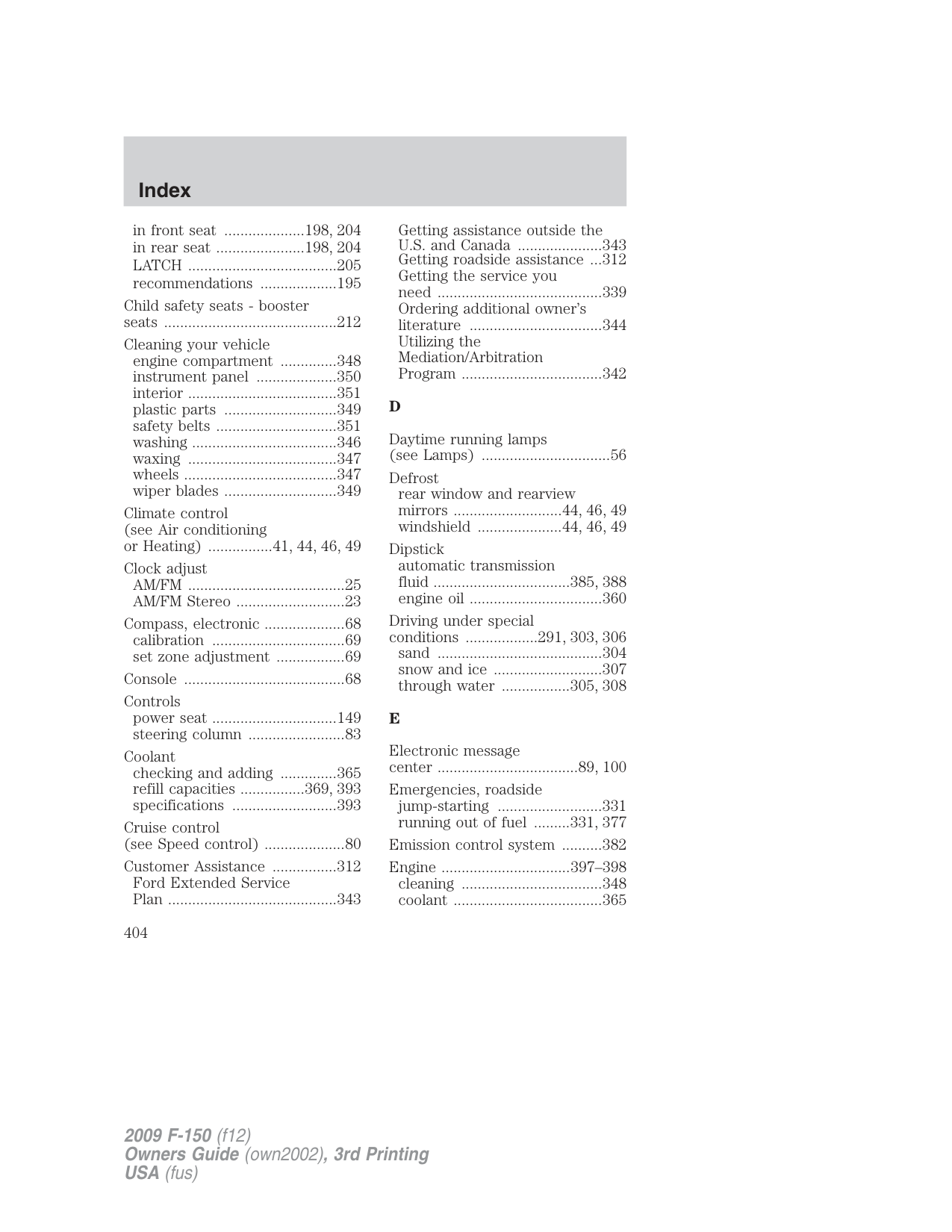
|Spark plug gap|0.052–0.056 inch (1.32–1.42mm)|0.039–0.043 inch (1.0–1.1mm)|0.039–0.043 inch (1.0–1.1mm)| |Compression ratio|9.4:1|9.8:1|9.85:1|
*5.4L 3V FFV engines only.
Engine drivebelt routing
IDENTIFYING YOUR VEHICLE Safety Compliance Certification Label
The National Highway Traffic Safety Administration Regulations require that a Safety Compliance Certification Label be affixed to a vehicle and prescribe where the Safety Compliance Certification Label may be located. The Safety Compliance Certification Label is located on the structure (B-Pillar) by the trailing edge of the driver’s door or the edge of the driver’s door.
###### Vehicle identification number (VIN)
The vehicle identification number is located on the driver side instrument panel.
######## XXXXXXXXXXXXXXXXX
Please note that in the graphic, XXXX is representative of your vehicle identification number.
The Vehicle Identification Number (VIN) contains the following information:
| | | |---|---| | | |
| | | |---|---| | | |
| | | |---|---| | | |
###### TRANSMISSION CODE DESIGNATIONS
You can find a transmission code on the Safety Compliance Certification Label. The following table tells you which transmission each code represents.
|Description|Code| |---|---| |Four-speed automatic (4R75E)|Q| |Six-speed automatic (6R80)|6|
Accessories
###### GENUINE FORD ACCESSORIES FOR YOUR VEHICLE
A wide selection of Genuine Ford Accessories are available for your vehicle through your local Ford or Ford of Canada dealer. These quality accessories have been specifically engineered to fulfill your automotive needs; they are custom designed to complement the style and aerodynamic appearance of your vehicle. In addition, each accessory is made from high quality materials and meets or exceeds Ford’s rigorous engineering and safety specifications. Ford Motor Company will repair or replace any properly dealer-installed Genuine Ford Accessories found to be defective in factory-supplied materials or workmanship during the warranty period, as well as any component damaged by the defective accessories. The accessories will be warranted for whichever provides you the greatest benefit:
The following is a list of several Genuine Ford Accessories. Not all accessories are available for all models. For a complete listing of the accessories that are available for your vehicle, please contact your dealer or visit our online store at: www.fordaccessories.com.
Exterior style Bug shields Chrome exhaust tips Deflectors Running boards Splash guards Step bars Tonneau covers Wheels
Interior style Electrochromatic compass/temperature interior mirrors Floor mats
Accessories
Lifestyle Ash cup / smoker’s package Bedliners and bedmats Cargo organization and management Towing mirrors Trailer hitches, wiring harnesses and accessories
Peace of mind Mobile-Ease™ hands free communication system Remote start Vehicle security systems Wheel locks For maximum vehicle performance, keep the following information in mind when adding accessories or equipment to your vehicle:
###### A
Accessory delay ..........................74 AdvanceTrac ..............................274 Air cleaner filter ...............389, 392 Air conditioning ........41, 44, 46, 49
manual heating and air conditioning system .................41
Airbag supplemental restraint system ........................180, 187, 190 and child safety seats ............181 description ......................187, 190 disposal ....................................193 driver airbag ....181–182, 188, 191 indicator light .........183, 189, 192 operation .........181–182, 188, 191 passenger airbag ...............181–182, 188, 191 side airbag ...............................187
Ambulance packages ....................8 AM/FM .........................................24 Antifreeze (see Engine coolant) ................365 Anti-lock brake system (see Brakes) ..............................272 Anti-theft system ......................139
arming the system ..................141 Armrests ....................................147 Audio system (see Radio) ...22, 24 Automatic transmission driving an automatic overdrive .........................285, 288 fluid, adding ....................385, 388 fluid, checking ................385, 388 fluid, refill capacities ..............393 fluid, specification ..................393
Auxiliary input jack (Line in) ....32
Axle
lubricant specifications ..........393 refill capacities ........................393
###### B
Battery .......................................363 acid, treating emergencies .....363 jumping a disabled battery ....331 maintenance-free ....................363 replacement, specifications ...392 servicing ..................................363
Bed extender ............................116 Belt-Minder .............................175
deactivating/activating the Belt-Minder ...........................178 Booster seats .............................212 Brakes ........................................272
anti-lock ...................................272 anti-lock brake system (ABS) warning light ...........................273 fluid, checking and adding ....385 fluid, refill capacities ..............393 fluid, specifications .................393 lubricant specifications ..........393 parking ....................................273 shift interlock ..................281, 284 trailer .......................................257
Bulbs ............................................59
###### C
Capacities for refilling fluids ....393 Cargo management system ......119
####### CD ................................................24Cell phone use ..............................8Changing a tire .........................322
Child safety seats ......................197 attaching with tether straps ..207
in front seat ....................198, 204 in rear seat ......................198, 204 LATCH .....................................205 recommendations ...................195
Child safety seats - booster seats ...........................................212
Cleaning your vehicle
engine compartment ..............348 instrument panel ....................350 interior .....................................351 plastic parts ............................349 safety belts ..............................351 washing ....................................346 waxing .....................................347 wheels ......................................347 wiper blades ............................349
Climate control (see Air conditioning or Heating) ................41, 44, 46, 49
Clock adjust
AM/FM .......................................25 AM/FM Stereo ...........................23
Compass, electronic ....................68 calibration .................................69 set zone adjustment .................69
Console ........................................68 Controls
power seat ...............................149 steering column ........................83
Coolant
checking and adding ..............365 refill capacities ................369, 393 specifications ..........................393
Cruise control (see Speed control) ....................80 Customer Assistance ................312
Ford Extended Service Plan ..........................................343
Getting assistance outside the U.S. and Canada .....................343 Getting roadside assistance ...312 Getting the service you need .........................................339 Ordering additional owner’s literature .................................344 Utilizing the Mediation/Arbitration Program ...................................342
###### D
Daytime running lamps (see Lamps) ................................56
Defrost rear window and rearview mirrors ...........................44, 46, 49 windshield .....................44, 46, 49
Dipstick automatic transmission fluid ..................................385, 388 engine oil .................................360
Driving under special conditions ..................291, 303, 306 sand .........................................304 snow and ice ...........................307 through water .................305, 308
###### E
Electronic message center ...................................89, 100
Emergencies, roadside
jump-starting ..........................331 running out of fuel .........331, 377
Emission control system ..........382 Engine ................................397–398
cleaning ...................................348 coolant .....................................365
fail-safe cooling .......................369 idle speed control ...................363 lubrication specifications .......393 refill capacities ........................393 service points ..................357–358
Engine block heater .................270 Engine oil ..................................360
checking and adding ..............360 dipstick ....................................360 filter, specifications ........362, 392 recommendations ...................362 refill capacities ........................393 specifications ..........................393
Event data recording ....................7 Exhaust fumes ..........................270
###### F
Fail safe cooling ........................369 Flexible Fuel Vehicle (FFV) ....371 Floor mats .................................112 Fluid capacities .........................393 Fog lamps ....................................55 Four-Wheel Drive vehicles .......296
driving off road .......................301 electronic shift ........................299 indicator light .........................296 lever operated shift ................297 preparing to drive your vehicle .....................................281
Fuel ............................................371 calculating fuel economy ..........................101, 378 cap ...........................................374 capacity ...................................393 choosing the right fuel ...........375 comparisons with EPA fuel economy estimates .................381 detergent in fuel .....................375
filler funnel .............................377 filling your vehicle with fuel ...........................371, 374, 378 filter, specifications ........371, 392 improving fuel economy ........378 octane rating ...........376, 397–398 quality ..............................376–377 running out of fuel .........331, 377 safety information relating to automotive fuels .....................371
Fuel - flex fuel vehicle (FFV) .........................371, 375–376 Fuses ..................................314–315
###### G
Gas cap (see Fuel cap) ............374 Gas mileage (see Fuel economy) .................378 Gauges .........................................18
transmission fluid temperature gauge ...................22
###### H
Hazard flashers .........................313 Headlamps ...................................54
aiming ..................................56–57 autolamp system .......................54 bulb specifications ....................60 daytime running lights .............56 flash to pass ..............................55 high beam .................................55 replacing bulbs .........................61 turning on and off ....................54
Heating heating and air conditioning system .....................41, 44, 46, 49
Homelink wireless control system ..........................................86
Hood ..........................................356
###### I
Ignition .......................265, 397–398 Illuminated visor mirror .............67 Infant seats (see Safety seats) .....................197 Inspection/maintenance (I/M) testing ........................................384 Instrument panel
cleaning ...................................350 cluster ........................................12
###### J
Jack ............................................322 positioning ...............................322 storage .....................................322
Jump-starting your vehicle ......331
###### K
Keyless entry system
autolock ...................................127 keypad .....................................138 locking and unlocking doors ..139 programming entry code .......139
Keys ...................................126, 141 positions of the ignition .........265
###### L
Lamps autolamp system .......................54 bulb replacement specifications chart ..................60 daytime running light ...............56 fog lamps ...................................55 headlamps .................................54
headlamps, flash to pass ..........55 interior lamps .....................58–59 replacing bulbs ...................61, 64
LATCH anchors .........................205 Lights, warning and indicator ....12
anti-lock brakes (ABS) ..........273 Limited-slip axle .......................280 Load limits .................................244 Loading instructions .................250 Locks
autolock ...................................127 childproof ................................130 doors ........................................126
Lubricant specifications ...........393 Lug nuts ....................................330 Lumbar support, seats .....148–149
Message center ...................89, 100 english/metric button .............106 system check button ..............103 warning messages .............95, 107
Mirrors ...................................74–75 automatic dimming rearview mirror ........................................74 fold away ...................................76 heated ......................44, 46, 49, 77 programmable memory ..........132 side view mirrors (power) .......75 signal .........................................77
Moon roof ....................................85 Motorcraft parts ................354, 392
Oil (see Engine oil) ..................360 P
Parking brake ............................273 Parts (see Motorcraft parts) ....392 Passenger Occupant Classification Sensor .................163 Power deployable running boards ..........................................78 Power distribution box (see Fuses) .......................315, 318 Power door locks ......................126 Power mirrors .............................75 Power point .................................70 Power steering ..........................279
fluid, checking and adding ....384 fluid, refill capacity ................393 fluid, specifications .................393
Power Windows ...........................72 Preparing to drive your vehicle ........................................281
R Radio ......................................22, 24
6-CD in dash .............................24 Recommendations for attaching safety restraints for children ......................................195 Relays ........................................314 Remote entry system ...............130
illuminated entry ....................136 locking/unlocking doors ................................131–132 panic alarm .............................132 replacement/additional transmitters .............................135
replacing the batteries ...........134 Reverse camera .........................294 Reverse sensing system ...........292 Roadside assistance ..................312
###### S
Safety belts (see Safety restraints) ............161,
165–167, 170–172, 174 Safety Canopy ...........187–188, 190 Safety defects, reporting ..........345 Safety restraints .......161, 165–167,
170–174 Belt-Minder ...........................175 Belt-Minder , deactivating/activating ...........178 extension assembly ................179 for adults .........166–167, 170–172 for children .............................193 lap belt ....................................169 Occupant Classification Sensor ......................................163 warning light and chime ...............................174–175
Safety restraints - LATCH anchors ......................................205 Safety seats for children ..........197 Safety Compliance Certification Label ....................398 Satellite Radio (if equipped) .....24 Satellite Radio Information ........37 Seats ..........................................143
child safety seats ....................197 cleaning ...................................352 climate control ............46, 49, 155 easy access/easyout feature ..152 heated ................................44, 153
memory seat ...................132, 151
SecuriCode keyless entry system ........................................138
SecuriLock passive anti-theft system ................................139, 141 Servicing your vehicle ..............355 Setting the clock .........................25
AM/FM stereo ...........................23 Snowplowing .................7, 308–310 Spark plugs, specifications .............392, 397–398 Special notice
ambulance conversions ..............8 four-wheel drive vehicles ............................310–311 utility-type vehicles ....................8
Specification chart, lubricants ...................................393 Speed control ..............................80 Starting a flex fuel vehicle .......269 Starting your vehicle ................265–266, 268–269
jump starting ..........................331 Steering wheel
controls ......................................83 tilting .........................................66
Stereo
6-CD in dash .............................24 CD-MP3 .....................................24
SYNC ..........................................40
###### T
Tailgate ......................................113 Tilt steering wheel ......................66
Tire Pressure Monitoring System (TPMS)
Tires, Wheels and Loading ....233
Tires ...........................218–219, 322 alignment ................................226 care ..........................................222 changing ..........................322, 326 checking the pressure ............222 inflating ...................................220 label .........................................232 replacing ..................................224 rotating ....................................226 safety practices .......................225 sidewall information ...............228 snow tires and chains ............243 spare tire .................................323 terminology .............................220 tire grades ...............................219 treadwear ........................219, 223
Towing .......................................250 recreational towing .................263 Trailer Brake Controller-Integrated ..............257 trailer towing ..........................250
Trailer Brake Controller-Integrated ................257
Transfer case fluid checking .........................388
Transmission .............................281 brake-shift interlock (BSI) ................................281, 284 fluid, checking and adding (automatic) .....................385, 388 fluid, refill capacities ..............393 lubricant specifications ..........393
Turn signal ..................................58 U USB port ......................................34
###### V
Vehicle Identification Number (VIN) ..........................................399 Vehicle loading ..........................244 Ventilating your vehicle ...........270
####### WWarning lights (see Lights) .......12
Washer fluid ..............................359 Water, Driving through .............308 Windows
power .........................................72 Windshield washer fluid and wipers ..........................................65 checking and adding fluid .....359 replacing wiper blades ...........360