
Ask AI
— answers from the official manualAnswers from the official manual.
Common questions
Common Questions
10 totalHow do I factory reset the [product]?
Press and hold the Power button for 10 seconds until the LED flashes red. This clears all settings and returns the device to factory defaults. You will need to re-pair all connected devices after the reset.
What should I do if an electrical fuse blows?
Replace the blown fuse with a new one of the value stated on the serial label for the cabinet. Ensure to use only the specified type and rating as per the manual.
How often should I clean the condenser coil?
+Stayclear Condenser Coil: Clean every 12 to 18 weeks, Traditional Fin Condenser Coil: Every 4 to 6 weeks. Use only a brush or vacuum cleaner; avoid wire brushes and cleaning agents that can damage the coils.
What should I do if there is high temperature alarm?
The high temperature alarm indicates an issue with either T2 Evaporator probe failure or door open problem. Inspect these areas, ensure the door is closed and probes are functioning.
How do I perform a manual defrost operation?
To activate, press and hold the Power button while in 'run' mode for 5 seconds. After the display goes blank for 3 seconds and returns, a defrost cycle will start automatically.
How can I enter Adjustment Mode to make changes?
First press and release Keypad Security icon followed by Power button. Use the Increase and Decrease switches to scroll through available modes such as Set Point, Key Lock Security.
Full Manual
12 pages


Original Operation Instructions
By Appointment to Her Majesty Queen Elizabeth II Suppliers of Commercial Refrigeration Foster Refrigerator, King’s Lynn
EcoPro G2
Cabinet & Counter Models
Controller & Display - Versions FD1-11 & FD1-14


00-556483 November 2019 Issue 8 GB
A Division of ITW Ltd Foster Refrigerator Oldmedow Road King’s Lynn Norfolk, PE30 4JU
United KingdomISO 9001ISO 14001
Call: +44 (0)1553 691 122 Email: [email protected] www.fosterrefrigerator.co.uk
####### Models Applicable to This Manual
Single Cabinets
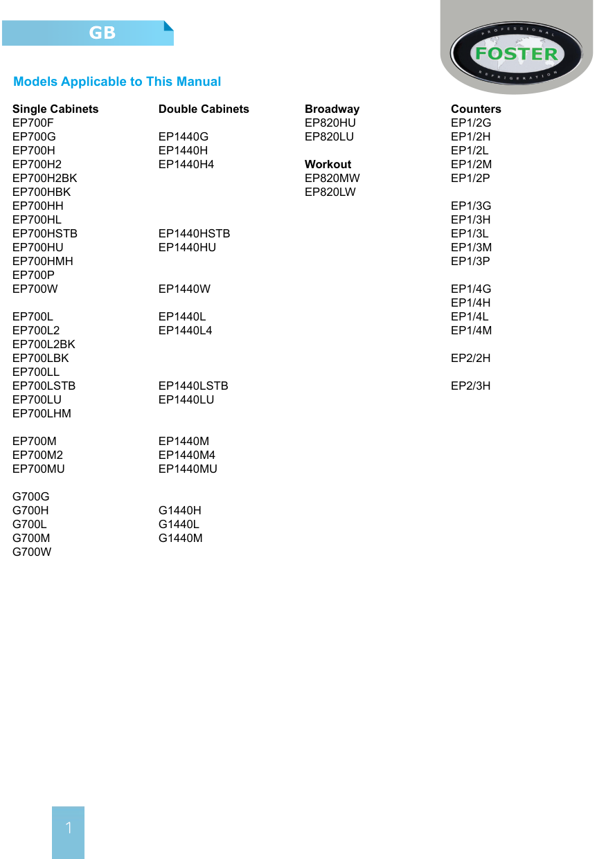
######## Double Cabinets
Broadway
Counters
EP820HU EP820LU
EP1/3L EP1/3M
Workout EP820MW EP820LW
EP1440HSTB EP1440HU
EP1440W EP1440L EP1440L4
EP1440LSTB EP1440LU
EP1440M EP1440M4 EP1440MU
G1440H G1440L G1440M
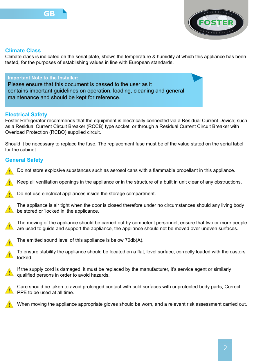
Climate Class Climate class is indicated on the serial plate, shows the temperature & humidity at which this appliance has been tested, for the purposes of establishing values in line with European standards.
Important Note to the Installer: Please ensure that this document is passed to the user as it contains important guidelines on operation, loading, cleaning and general maintenance and should be kept for reference.
Electrical Safety Foster Refrigerator recommends that the equipment is electrically connected via a Residual Current Device; such as a Residual Current Circuit Breaker (RCCB) type socket, or through a Residual Current Circuit Breaker with Overload Protection (RCBO) supplied circuit.
Should it be necessary to replace the fuse. The replacement fuse must be of the value stated on the serial label for the cabinet.
General Safety Do not store explosive substances such as aerosol cans with a flammable propellant in this appliance. Keep all ventilation openings in the appliance or in the structure of a built in unit clear of any obstructions. Do not use electrical appliances inside the storage compartment. The appliance is air tight when the door is closed therefore under no circumstances should any living body be stored or ‘locked in’ the applicance. The moving of the appliance should be carried out by competent personnel, ensure that two or more people are used to guide and support the appliance, the appliance should not be moved over uneven surfaces. The emitted sound level of this appliance is below 70db(A). To ensure stability the appliance should be located on a flat, level surface, correctly loaded with the castors locked. If the supply cord is damaged, it must be replaced by the manufacturer, it’s service agent or similarly qualified persons in order to avoid hazards. Care should be taken to avoid prolonged contact with cold surfaces with unprotected body parts, Correct PPE to be used at all time. When moving the appliance appropriate gloves should be worn, and a relevant risk assessment carried out.


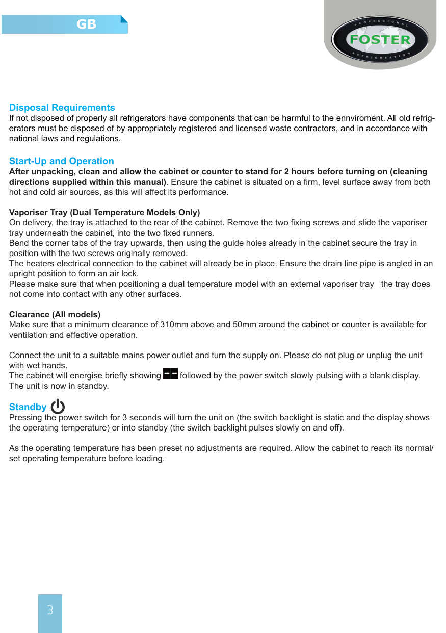
Disposal Requirements If not disposed of properly all refrigerators have components that can be harmful to the ennviroment. All old refrigerators must be disposed of by appropriately registered and licensed waste contractors, and in accordance with national laws and regulations.
Start-Up and Operation After unpacking, clean and allow the cabinet or counter to stand for 2 hours before turning on (cleaning directions supplied within this manual). Ensure the cabinet is situated on a firm, level surface away from both hot and cold air sources, as this will affect its performance.
Vaporiser Tray (Dual Temperature Models Only) On delivery, the tray is attached to the rear of the cabinet. Remove the two fixing screws and slide the vaporiser tray underneath the cabinet, into the two fixed runners. Bend the corner tabs of the tray upwards, then using the guide holes already in the cabinet secure the tray in position with the two screws originally removed. The heaters electrical connection to the cabinet will already be in place. Ensure the drain line pipe is angled in an upright position to form an air lock. Please make sure that when positioning a dual temperature model with an external vaporiser tray the tray does not come into contact with any other surfaces.
Clearance (All models) Make sure that a minimum clearance of 310mm above and 50mm around the cabinet or counter is available for ventilation and effective operation.
Connect the unit to a suitable mains power outlet and turn the supply on. Please do not plug or unplug the unit with wet hands. The cabinet will energise briefly showing followed by the power switch slowly pulsing with a blank display. The unit is now in standby.

Standby Pressing the power switch for 3 seconds will turn the unit on (the switch backlight is static and the display shows the operating temperature) or into standby (the switch backlight pulses slowly on and off).
As the operating temperature has been preset no adjustments are required. Allow the cabinet to reach its normal/ set operating temperature before loading.
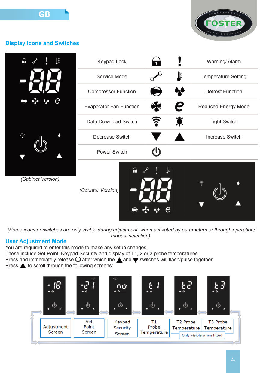
####### Display Icons and Switches


Keypad Lock Warning/ Alarm


Service Mode Temperature Setting


Compressor Function Defrost Function


Evaporator Fan Function Reduced Energy Mode


Data Download Switch Light Switch


Decrease Switch Increase Switch
Power Switch

(Cabinet Version)
(Counter Version)
(Some icons or switches are only visible during adjustment, when activated by parameters or through operation/ manual selection).
User Adjustment Mode You are required to enter this mode to make any setup changes. These include Set Point, Keypad Security and display of T1, 2 or 3 probe temperatures. Press and immediately release after which the and switches will flash/pulse together. Press to scroll through the following screens:


To exit this mode scroll back to the adjustment screen and press or wait for 30 seconds and the display will revert to the normal display showing the operating temperature.
Set Point and Other Mode Adjustments Access the adjustment mode as described above. Using the or switches to scroll to the mode that requires adjustments i.e ‘Set Point’ this is the minimum temperature the cabinet is allowed to cool down to (the display shows the temperature and flash/pulsing icon ). To adjust this press and release the icon will show constantly. Adjust the setting with the or switch. Confirm the change by pressing and releasing again, the next mode will automatically show. Scroll through the modes with the or switch until you return to the adjustment screen and press and release to exit and save.


If at any point the display is left for 30 seconds it will revert to the normal display and no changes will be saved.
Keypad Security Settings Access the ‘Keypad Security’ screen as described above. The screen will show the current status, initially preset to ‘ ’, with flashing. Press and release and will show constantly. (If you modify this setting with to show ‘ ‘ the keypad will be locked, will show constantly and the cabinet will not be able to be put into standby, carry out a manual defrost, adjust temperature set point, download data or switch on/off the units lights. To confirm any change you must press again so the next screen ‘ ’ shows). Exit any of the ‘Adjustment Modes’ as described above.


Internal Light (where fitted) To switch on the lights press and release so that the switch backlight is on continuously. To switch off press and release and the switch backlight will flash/pulse.


Shelves and Supports G2 shelving for low, high or meat temperature cabinets consist of two trayslides per shelf. These slot directly into the rear of the cabinet’s airduct and have ladderacking to support the front. Shelves are the standard wire gastronorm style that slide onto the trayslides. Fish cabinets come with fixed racking and fish bins, wine cabinets with the required bottle racking/holder assembly. Both of these are fitted instead of standard shelving.
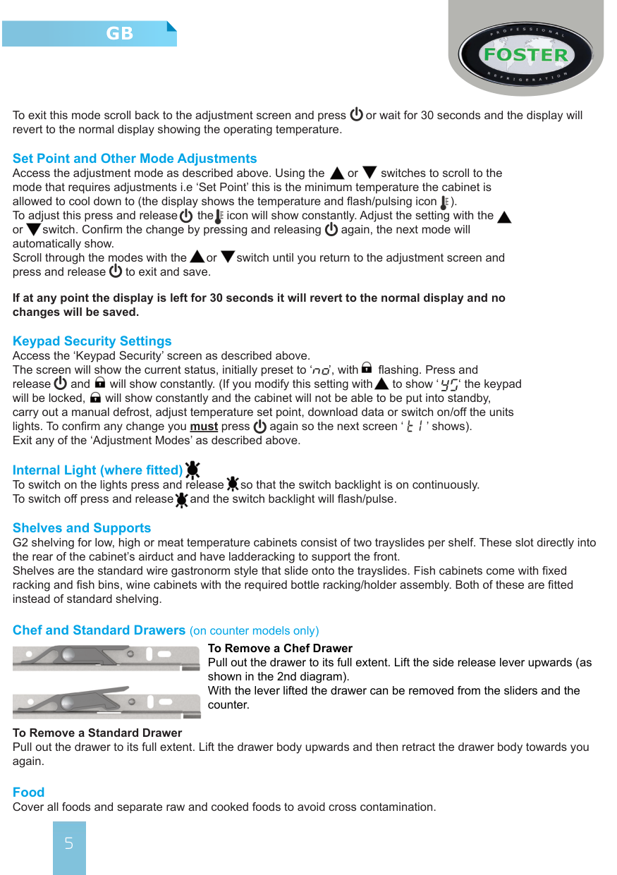
Chef and Standard Drawers (on counter models only) To Remove a Chef Drawer Pull out the drawer to its full extent. Lift the side release lever upwards (as shown in the 2nd diagram). With the lever lifted the drawer can be removed from the sliders and the counter.


To Remove a Standard Drawer Pull out the drawer to its full extent. Lift the drawer body upwards and then retract the drawer body towards you again. Food Cover all foods and separate raw and cooked foods to avoid cross contamination.
Loading and Airflow Ensure that there is no more than 40kg of evenly distribute product placed on or within each shelf or drawer. Always ensure the air can circulate around/through the stored product. It is important that for optimal energy performance that adequate airflow is maintained around the perimeter of the shelves, and around all stored products. On all models please ensure that no product is placed on the unit base.
Door & Drawer Lock To lock the door or drawer insert the key and turn 90°, turn in the opposite direction to unlock.
Defrost All Foster G2 cabinets are fitted with a fully automatic defrost system to ensure that the evaporator coil remains free from ice during normal use. Melt-water is evaporated using either the heat from the refrigeration system or a separate electric heater (dependent upon model and configuration)
To activate a manual defrost - while the cabinet is in ‘run’ mode press and hold for 5 seconds. After 3 seconds the display will go blank then return after a further 2 seconds. At this point a defrost will be performed (subject to underlying operating parameters), this will terminate automatically.
Cleaning and Maintenance Important: Before cleaning, the unit should be put into standby and then the power supply should be turned off at the mains. Please do not plug or unplug the unit with wet hands. Only when cleaning has been completed and the unit is dry should the cabinet be turned back on at the mains.
Suitable P.P.E (Personal Protective Equipment) should be worn at all times. Regular Maintenance:
> As and when required remove all product and shelving (beware of cold and or sharp components) from the unit. Clean exterior and interior surfaces with mild liquid detergent, following the directions on the pack at all times. Rinse surfaces with a damp cloth containing clean water. Never use wire wool, scouring pads/powders or high alkaline cleaning agents i.e bleaches, acids and chlorines as these may cause damage.
> All gaskets should be inspected on a regular basis and replaced if damaged. To clean, wipe with a warm
damp soapy cloth followed by a clean damp cloth. Finally thoroughly dry.
> Shelves and their supports can be removed for cleaning. The shelves are dishwasher safe; however the
vertical supports should be cleaned with warm soapy water then rinsed and dried.
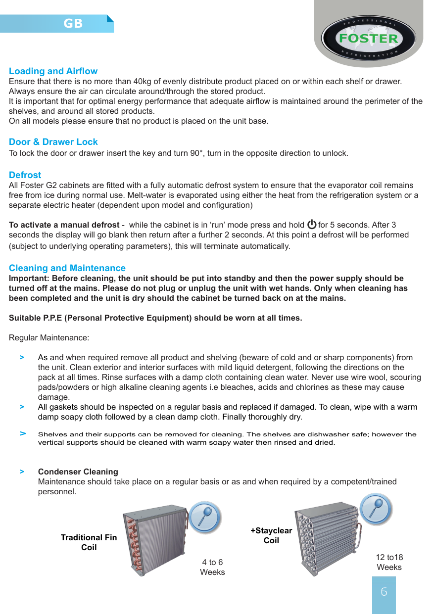
> Condenser Cleaning Maintenance should take place on a regular basis or as and when required by a competent/trained personnel.


+Stayclear CoilTraditional Fin
Coil
12 to18 Weeks
4 to 6 Weeks
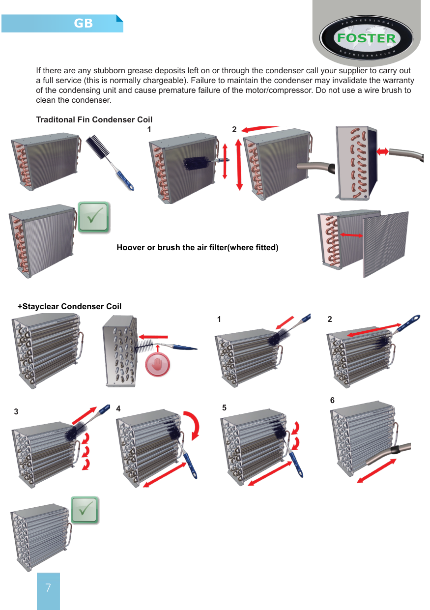
If there are any stubborn grease deposits left on or through the condenser call your supplier to carry out a full service (this is normally chargeable). Failure to maintain the condenser may invalidate the warranty of the condensing unit and cause premature failure of the motor/compressor. Do not use a wire brush to clean the condenser.
Traditonal Fin Condenser Coil
21


Hoover or brush the air filter(where fitted)
+Stayclear Condenser Coil


21
3 4 5


6

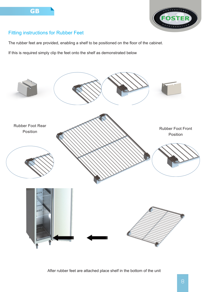
###### Fitting instructions for Rubber Feet
The rubber feet are provided, enabling a shelf to be positioned on the floor of the cabinet.
If this is required simply clip the feet onto the shelf as demonstrated below


Rubber Foot Rear Position
Rubber Foot Front Position


After rubber feet are attached place shelf in the bottom of the unit
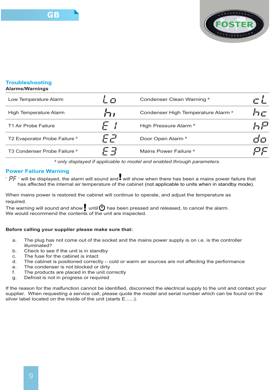
######### Troubleshooting Alarms/Warnings
Low Temperature Alarm Condenser Clean Warning #
High Temperature Alarm Condenser High Temperature Alarm #
Power Failure Warning ‘ ‘ will be displayed, the alarm will sound and will show when there has been a mains power failure that


has affected the internal air temperature of the cabinet (not applicable to units when in standby mode).
When mains power is restored the cabinet will continue to operate, and adjust the temperature as required. The warning will sound and show until has been pressed and released, to cancel the alarm. We would recommend the contents of the unit are inspected.

########### Before calling your supplier please make sure that:
If the reason for the malfunction cannot be identified, disconnect the electrical supply to the unit and contact your supplier. When requesting a service call, please quote the model and serial number which can be found on the silver label located on the inside of the unit (starts E......).
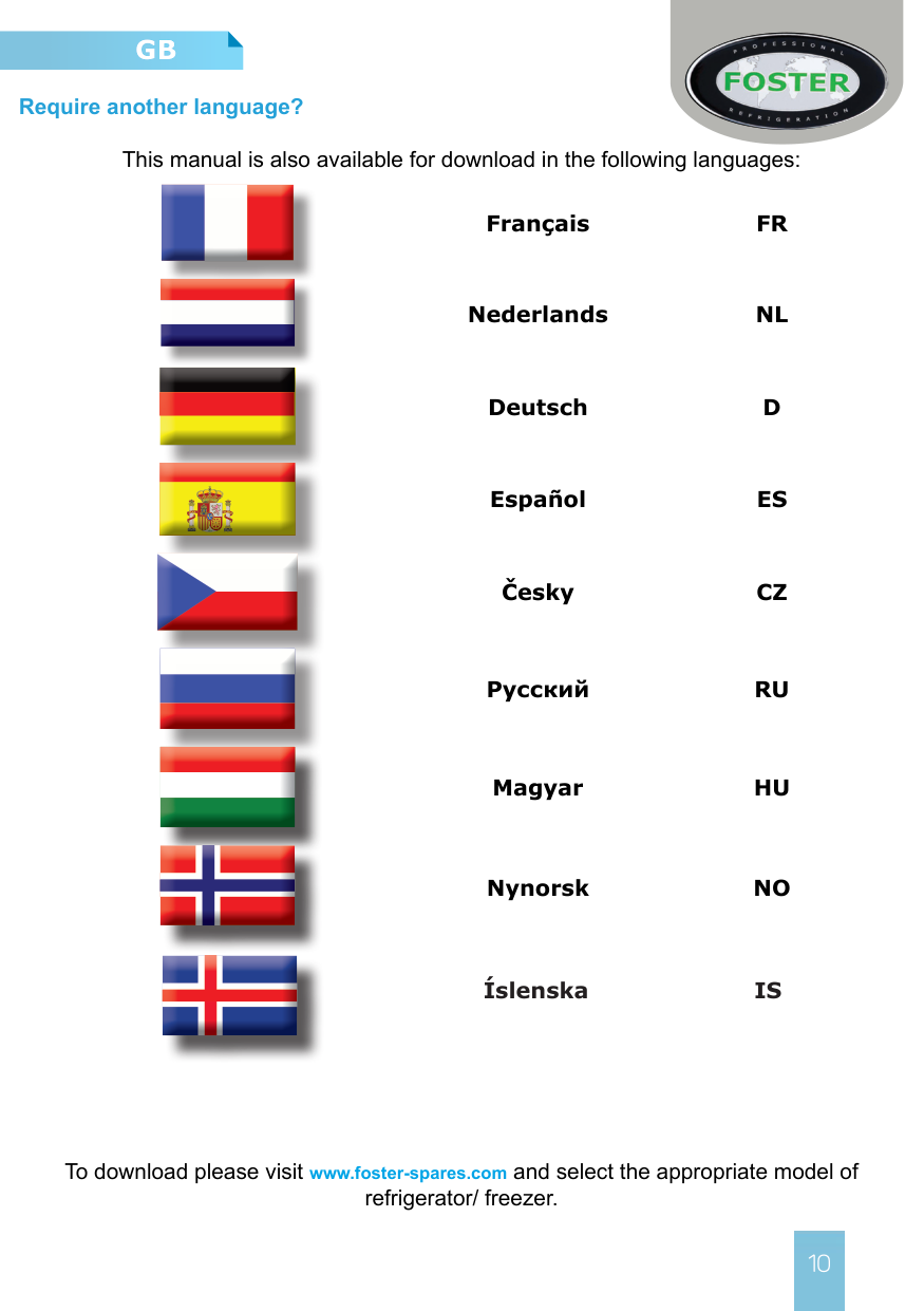
##### Require another language?
This manual is also available for download in the following languages:
Français FR
Nederlands NL
Deutsch D
Español ES
Česky CZ
Pусский RU
Magyar HU
Nynorsk NO
Íslenska IS

To download please visit www.foster-spares.com and select the appropriate model of refrigerator/ freezer.


########## UK Head Office
Foster Refrigerator Oldmedow Road Kings Lynn Norfolk PE30 4JU
a Division of ITW (UK) Ltd Tel: +44 (0)1553 691 122
Email: [email protected] Website: www.fosterrefrigerator.co.uk
