
Ask AI
— answers from the official manualAnswers from the official manual.
Common questions
Common Questions
18 totalWhat is the warranty period and what does it cover?
The charger comes with a full 12-month warranty from the date of purchase against all manufacturing defects. The warranty covers defects in design or manufacture that cause the product to fail to perform as described, with the company choosing to either repair or replace the product at their discretion. The warranty does not cover damage from improper use, faulty installation, or modification made during installation. (Page 8)
What does the red Fault LED flashing with no other LEDs on mean?
If only the Fault LED is quick flashing and all other LEDs are off, this indicates an over-temperature condition. You should let the unit cool down for some time or improve ventilation around the unit. A minimum air gap of 150mm around the unit is required. (Page 4)
What does it mean when the Fault LED and Solar LED are both quick flashing?
If both the Solar (Green) and Fault (Red) LEDs are quick flashing simultaneously with no other LEDs active, this indicates high voltage has been detected at the solar input. You should check the solar input voltage to resolve this issue. (Page 4)
How should the temperature sensor be connected?
The temperature sensor (thin black wire) should be connected to the negative terminal of the auxiliary battery for the best and most accurate temperature reading. If the sensor cannot reach the terminal, it can be affixed to the battery case itself using a small amount of removable adhesive. (Page 6)
What happens when LiFePO4 battery mode is selected?
When LiFePO4 battery setting is selected, the charger automatically activates a lithium 'wake' feature, sending out a pulse of power every minute. If a battery is detected, charging will continue; if no battery or a short circuit is detected, the charger will switch to standby mode. (Page 7)
What battery types are compatible with the Kings DCDC25A charger?
The charger is compatible with Lead Acid, AGM, Calcium, LiFePO4, and GEL battery types. For the 25A model, the recommended battery capacity is 60–250 Ah. For other Lithium-Ion batteries not listed, you should refer to the 'Charging Voltage Limits' section to confirm if the charging voltage is applicable. (Page 2)
Show 12 more questions
What fuse size is recommended for the 25A DCDC model?
What does a quick flash of LEDs indicate?
How do I install the DCDC charger properly?
What voltage range is suitable for the solar input?
How do I address a high voltage fault indication?
How do I set up the temperature sensor?
What are the recommended fuse sizes?
What happens when a LiFePO4 battery setting is selected?
What is the warranty period?
Where should the DCDC charger NOT be installed?
How do I change the battery type setting on the charger?
Why is my charger not starting immediately after connection?
Full Manual
8 pages
User Manual
Sku: Akep-Dcdc25A_01 & Akep-Dcdc40A_01
Dcdc Battery Charger
Please Read And Understand This Manual
Completely Before Using This Product.
2
V1.15
2. Technical Data
1. Safety Information
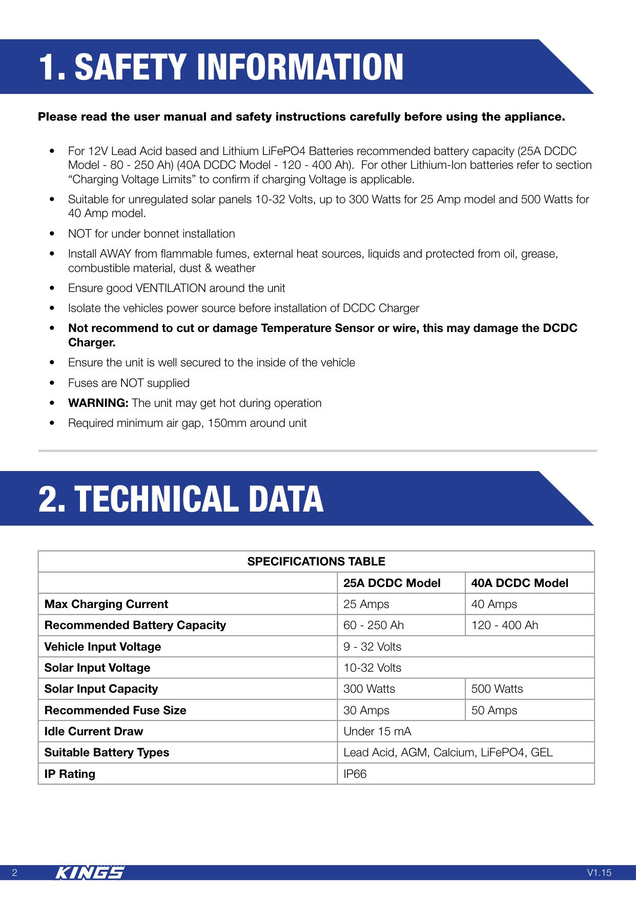
Please read the user manual and safety instructions carefully before using the appliance. • For 12V Lead Acid based and Lithium LiFePO4 Batteries recommended battery capacity (25A DCDC Model - 80 - 250 Ah) (40A DCDC Model - 120 - 400 Ah). For other Lithium-Ion batteries refer to section “Charging Voltage Limits” to confirm if charging Voltage is applicable. • Suitable for unregulated solar panels 10-32 Volts, up to 300 Watts for 25 Amp model and 500 Watts for 40 Amp model. • NOT for under bonnet installation • Install AWAY from flammable fumes, external heat sources, liquids and protected from oil, grease, combustible material, dust & weather • Ensure good VENTILATION around the unit • Isolate the vehicles power source before installation of DCDC Charger • Not recommend to cut or damage Temperature Sensor or wire, this may damage the DCDC Charger. • Ensure the unit is well secured to the inside of the vehicle • Fuses are NOT supplied • WARNING: The unit may get hot during operation • Required minimum air gap, 150mm around unitSpecifications Table
25A DCDC Model 40A DCDC Model Max Charging Current 25 Amps 40 Amps Recommended Battery Capacity 60 - 250 Ah 120 - 400 Ah Vehicle Input Voltage 9 - 32 Volts Solar Input Voltage 10-32 Volts Solar Input Capacity 300 Watts 500 Watts Recommended Fuse Size 30 Amps 50 Amps Idle Current Draw Under 15 mA Suitable Battery Types Lead Acid, AGM, Calcium, LiFePO4, GEL IP RatingIp66

3
V1.15
3. Leds & Faults Indications
3.1 Led Charge Indicator
Alternator / Solar LED Battery Type LED Charging Stage Short flash GREEN Solid GREEN Bulk or Absorption Long flash GREEN Solid GREEN FloatOperation Modes
25A and 40A Models Vehicle Charging System Turn On Turn Off 12 Volt Standard Alternator Above 13.1 Volts Under 12.8 Volts 24 Volt Standard Alternator Above 26.2 Volts Under 25.6 Volts 12 Volt Smart Alternator Above 12.0 Volts Under 11.8 Volts 24 Volt Smart Alternator Above 24.0 Volts Under 23.6 Volts Long Flash = 1s off, 2s on, 2s off Short Flash = 0.5s off, 0.5s on, 0.5s, off SOLID ON = light on continuously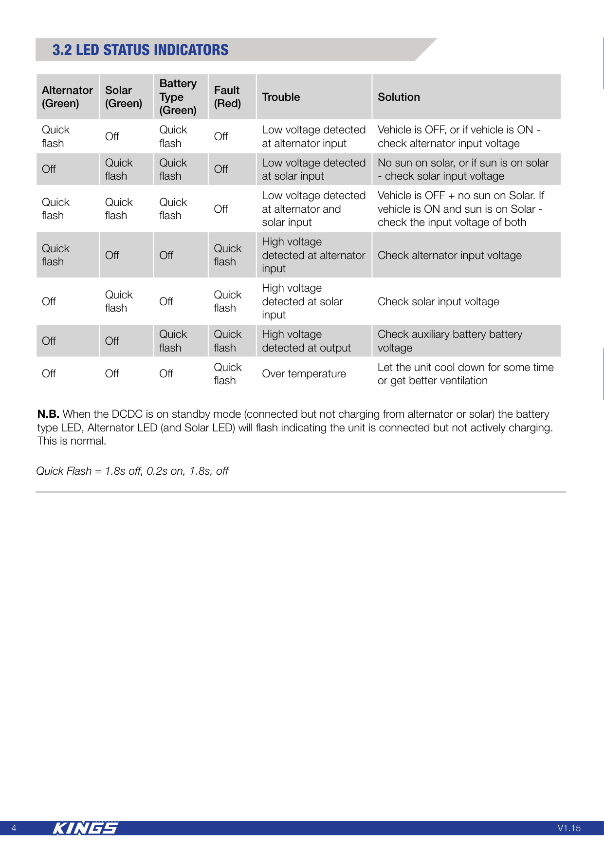
4
V1.15
3.2 Led Status Indicators
Alternator (Green) Solar (Green) Battery Type (Green) Fault (Red) Trouble Solution Quick flash Off Quick flash Off Low voltage detected at alternator input Vehicle is OFF, or if vehicle is ON - check alternator input voltage Off Quick flash Quick flash Off Low voltage detected at solar input No sun on solar, or if sun is on solar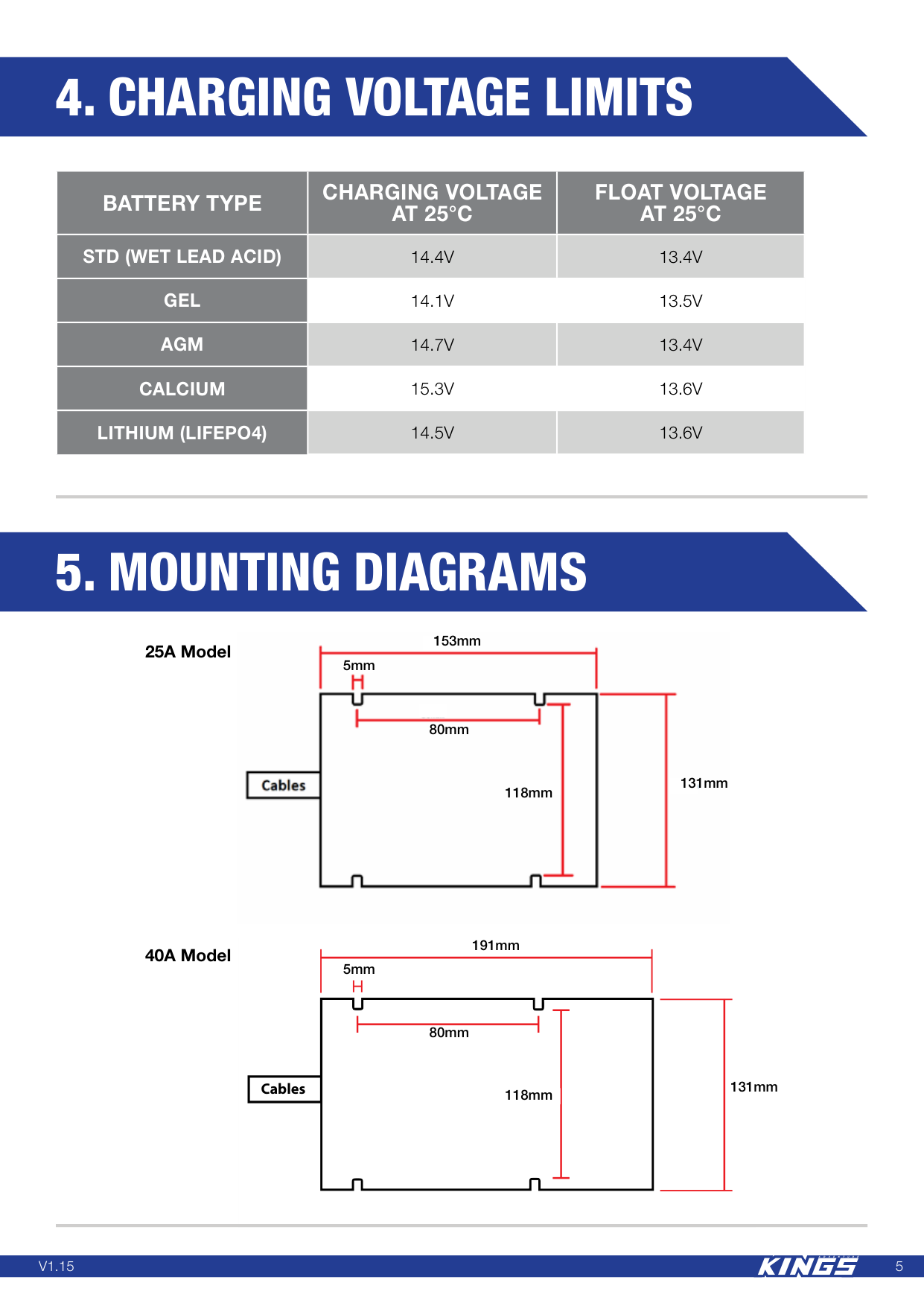
5
V1.15
CablesBattery Type
Charging Voltage
At 25°C
Float Voltage
At 25°C
Std (Wet Lead Acid)
14.4V
13.4V
Gel
14.1V
13.5V
Agm
14.7V
13.4V
Calcium
15.3V
13.6V
Lithium (Lifepo4)
14.5V
13.6V
4. Charging Voltage Limits
5. Mounting Diagrams
25A Model 40A Model 131mm 191mm 118mm 5mm 80mm 131mm 153mm 118mm 5mm 80mm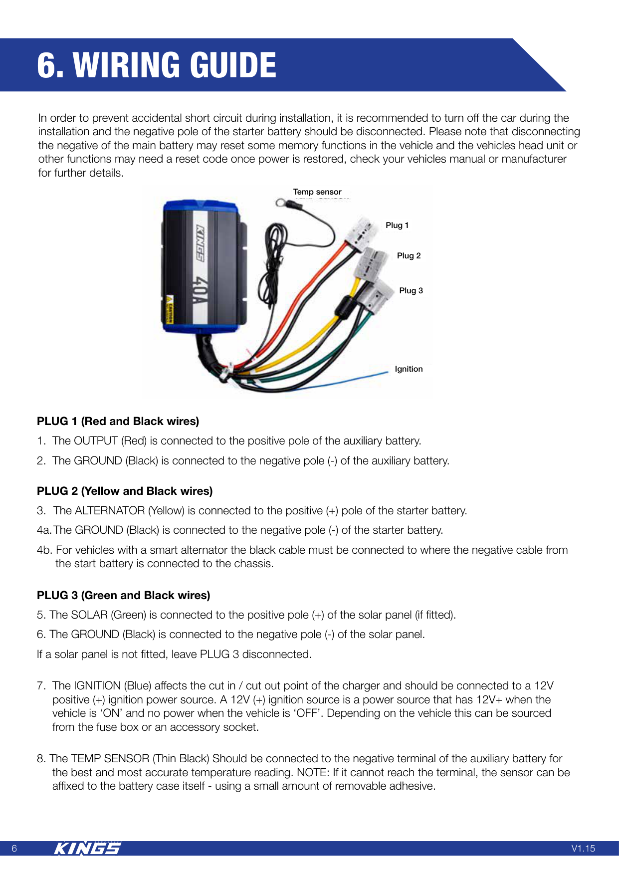
6
V1.15
6. Wiring Guide
Temp sensor Plug 2 Plug 3 Ignition Plug 1 PLUG 1 (Red and Black wires)
7
V1.15
7. Operation
8