
Ask AI
— answers from the official manualAnswers from the official manual.
Common questions
Common Questions
10 totalHow do I determine when maintenance is due on my Komatsu PC200-8M0?
The machine's monitor informs replacement time of oil and filters on the LCD screen as soon as the replacement interval is reached. Refer to your manual for specific maintenance intervals: Engine oil every 500 hours, hydraulic oil every 5,000 hours, hydraulic oil filter every 1,000 hours (Page 8).
What are the working modes available in my Komatsu PC200-8M0?
The Komatsu PC200-8M0 offers six working modes: Power Mode (P), Economy Mode (E), Lifting Mode (L), Breaker Mode (B), Attachment Power Mode (ATT/P), and Attachment Economy Mode (ATT/E) to match engine speed and pump output to the application conditions, thus providing flexibility in equipment performance(Pages 2-3).
What safety features does my Komatsu PC200-8M0 have?
The machine includes several safety features: a Roll Over Protection System (ROPS) cab meeting ISO 12117-2 standards for excavators, automatic decelerator to help prevent operator fatigue and increase productivity, rear view mirror system (optional), and large side-view mirrors and additional rear and side mirrors that meet visibility requirements (ISO 5006)(Page 5).
How can I improve fuel efficiency on my Komatsu PC200-8M0?
Ensure you are operating in appropriate modes which match engine and hydraulic needs (Power Mode P for maximum production or Economy Mode E for better economy). Use features such as the Power Max. switch for short-term high power output, and the ECO gauge to track efficient fuel use under green range operation(Page 4-5).
Where can I find information about my Komatsu PC200-8M0's bucket options?
Refer to the special purpose buckets section starting on page 16 for diverse bucket capacity and specialized features. The manual includes specific recommendations by application type, including ditch cleaning buckets, trapezoidal buckets, slope finishing buckets, ripper buckets, single-shank rippers, three-shank rippers and more. Also, Komatsu's brand of buckets offers benefits such as low resistance excavation and high productivity(Page 16-20).
How can I monitor my Komatsu PC200-8M0’s engine temperature?
The large multi-lingual LCD color monitor on the excavator displays the engine water temperature gauge to keep you informed of this critical operational information(Page 7).
Show 4 more questions
What maintenance alerts does the Komatsu PC200-8M0 system provide?
What types of hydraulic breaker attachments can I use with my Komatsu PC200-8M0 excavator?
How can I ensure easy access for routine maintenance on my Komatsu PC200-8M0?
What safety guidelines should I follow for the operation of my Komatsu PC200-8M0?
Full Manual
28 pages
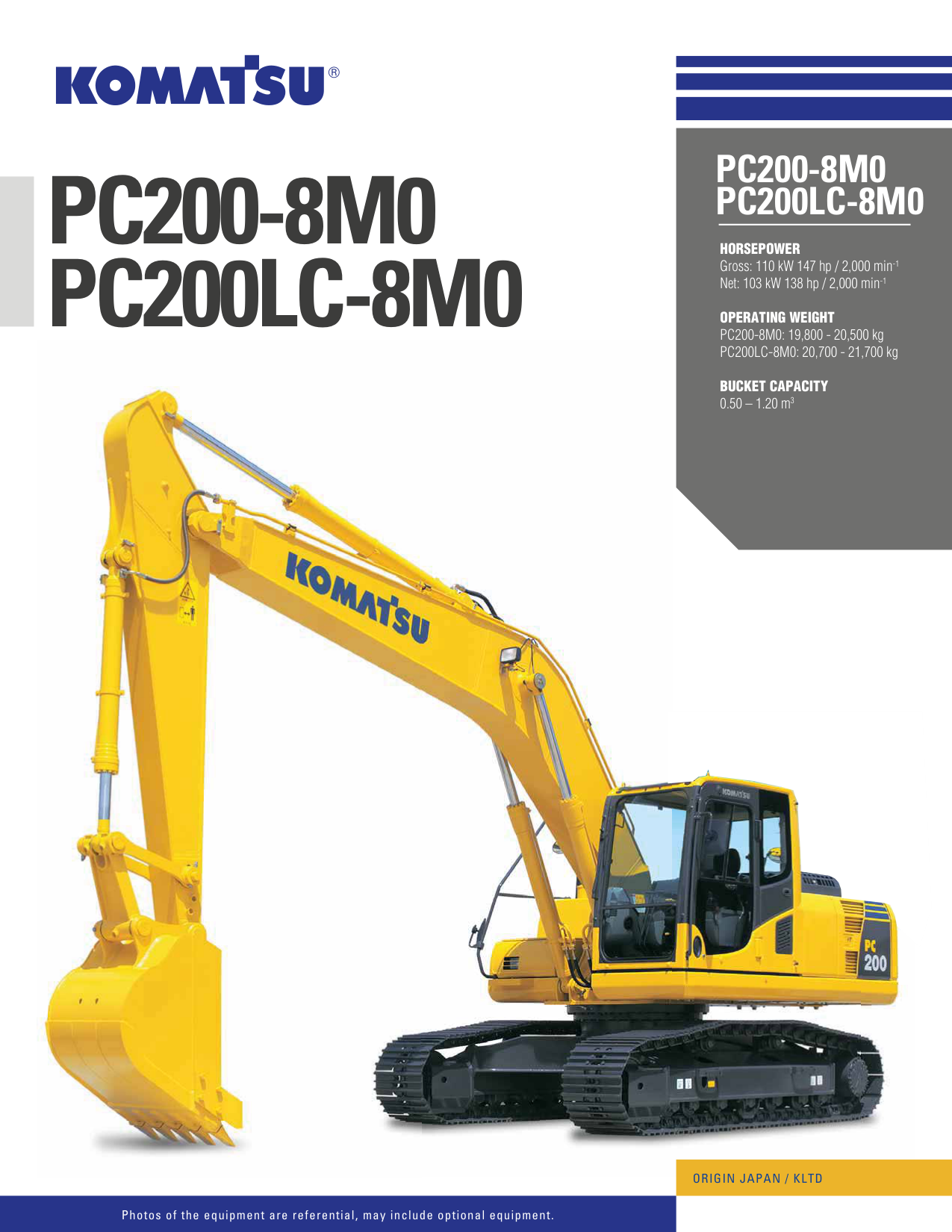
PC200-8M0 PC200LC-8M0 HORSEPOWER Gross: 110 kW 147 hp / 2,000 min-1 Net: 103 kW 138 hp / 2,000 min-1 OPERATING WEIGHT PC200-8M0: 19,800 - 20,500 kg PC200LC-8M0: 20,700 - 21,700 kg BUCKET CAPACITY 0.50 – 1.20 m3
PC200-8M0 PC200LC-8M0


####################### ORIGIN JAPAN / KLTD
Photos of the equipment are referential, may include optional equipment.
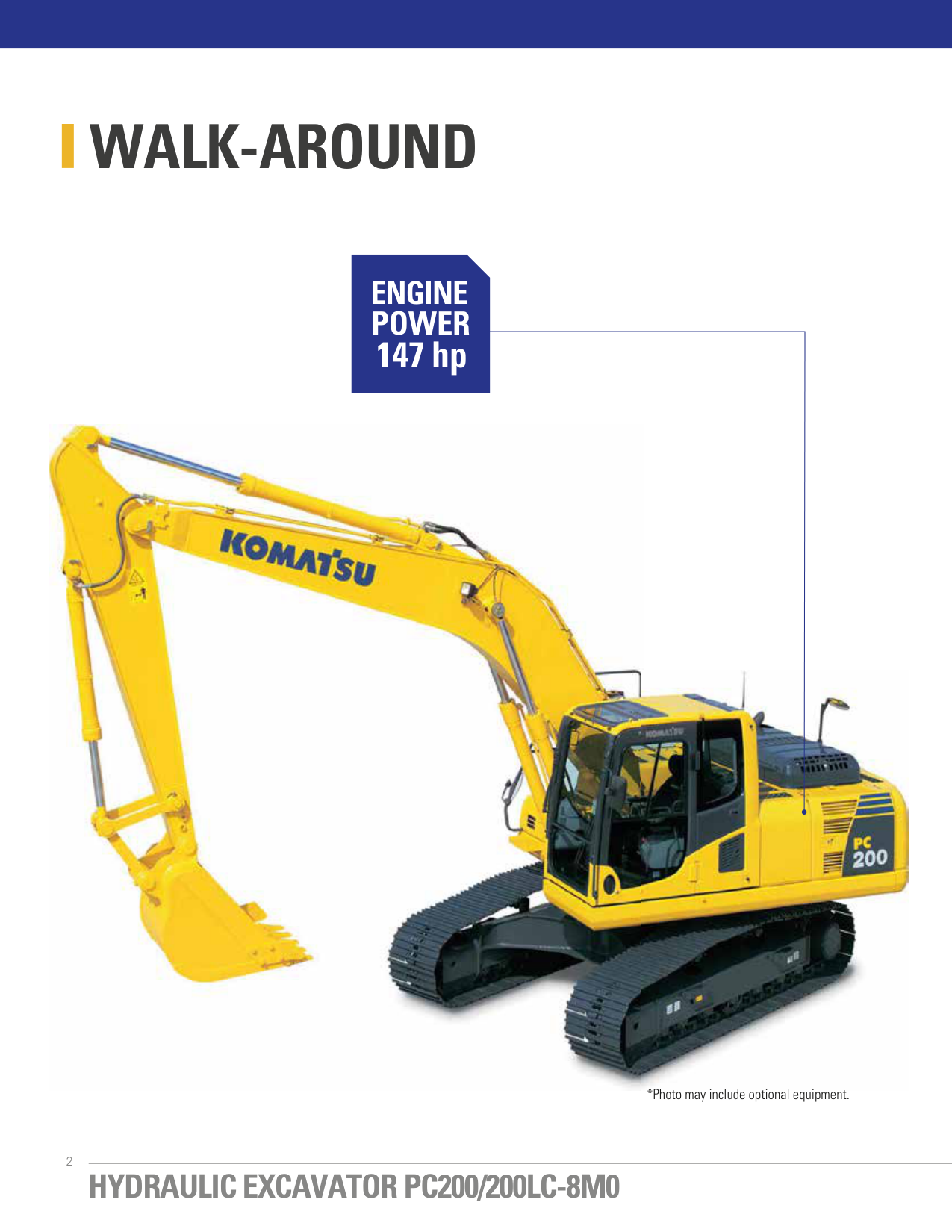
WALK-AROUND
#### ENGINE POWER 147 hp


*Photo may include optional equipment.
########## ECOLOGY & ECONOMY
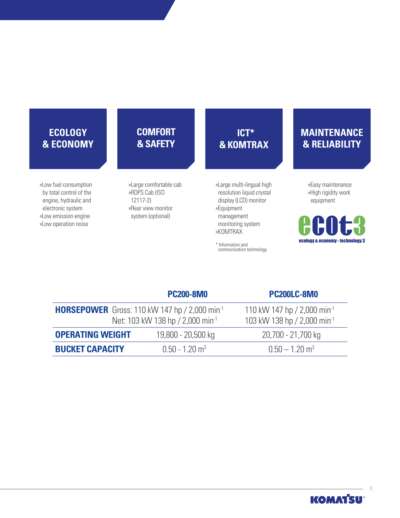
»Low fuel consumption by total control of the engine, hydraulic and electronic system
»Low emission engine »Low operation noise
########## COMFORT & SAFETY
»Large comfortable cab »ROPS Cab (ISO
12117-2)
»Rear view monitor system (optional)
########## ICT* & KOMTRAX
########## MAINTENANCE & RELIABILITY
»Large multi-lingual high resolution liquid crystal display (LCD) monitor
»Equipment management monitoring system
»KOMTRAX
»Easy maintenance »High rigidity work
equipment
PC200-8M0 PC200LC-8M0 HORSEPOWER Gross: 110 kW 147 hp / 2,000 min-1 110 kW 147 hp / 2,000 min-1
Net: 103 kW 138 hp / 2,000 min-1 103 kW 138 hp / 2,000 min-1 OPERATING WEIGHT 19,800 - 20,500 kg 20,700 - 21,700 kg BUCKET CAPACITY 0.50 - 1.20 m3 0.50 – 1.20 m3
ECOLOGY & ECONOMY
############# »Low fuel consumption
################## TOTAL VEHICLE CONTROL

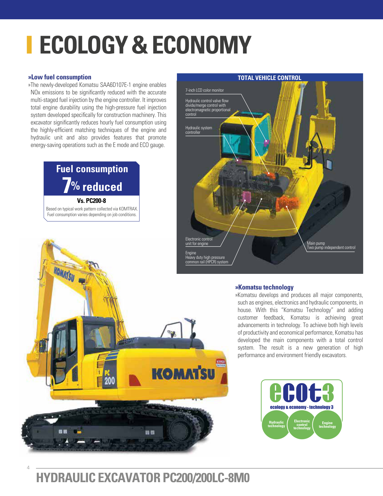
»The newly-developed Komatsu SAA6D107E-1 engine enables NOx emissions to be significantly reduced with the accurate multi-staged fuel injection by the engine controller. It improves total engine durability using the high-pressure fuel injection system developed specifically for construction machinery. This excavator significantly reduces hourly fuel consumption using the highly-efficient matching techniques of the engine and hydraulic unit and also provides features that promote energy-saving operations such as the E mode and ECO gauge.
7-inch LCD color monitor Hydraulic control valve flow divide/merge control with electromagnetic proportional control
Hydraulic system controller
Fuel consumption
7%
######## reduced
Vs. PC200-8 Based on typical work pattern collected via KOMTRAX. Fuel consumption varies depending on job conditions.
Electronic control unit for engine Main pump

Two pump independent control
Engine Heavy duty high pressure common rail (HPCR) system
############# »Komatsu technology
»Komatsu develops and produces all major components, such as engines, electronics and hydraulic components, in house. With this “Komatsu Technology” and adding customer feedback, Komatsu is achieving great advancements in technology. To achieve both high levels of productivity and economical performance, Komatsu has developed the main components with a total control system. The result is a new generation of high performance and environment friendly excavators.
Electronic control technology
Hydraulic technology
Engine technology

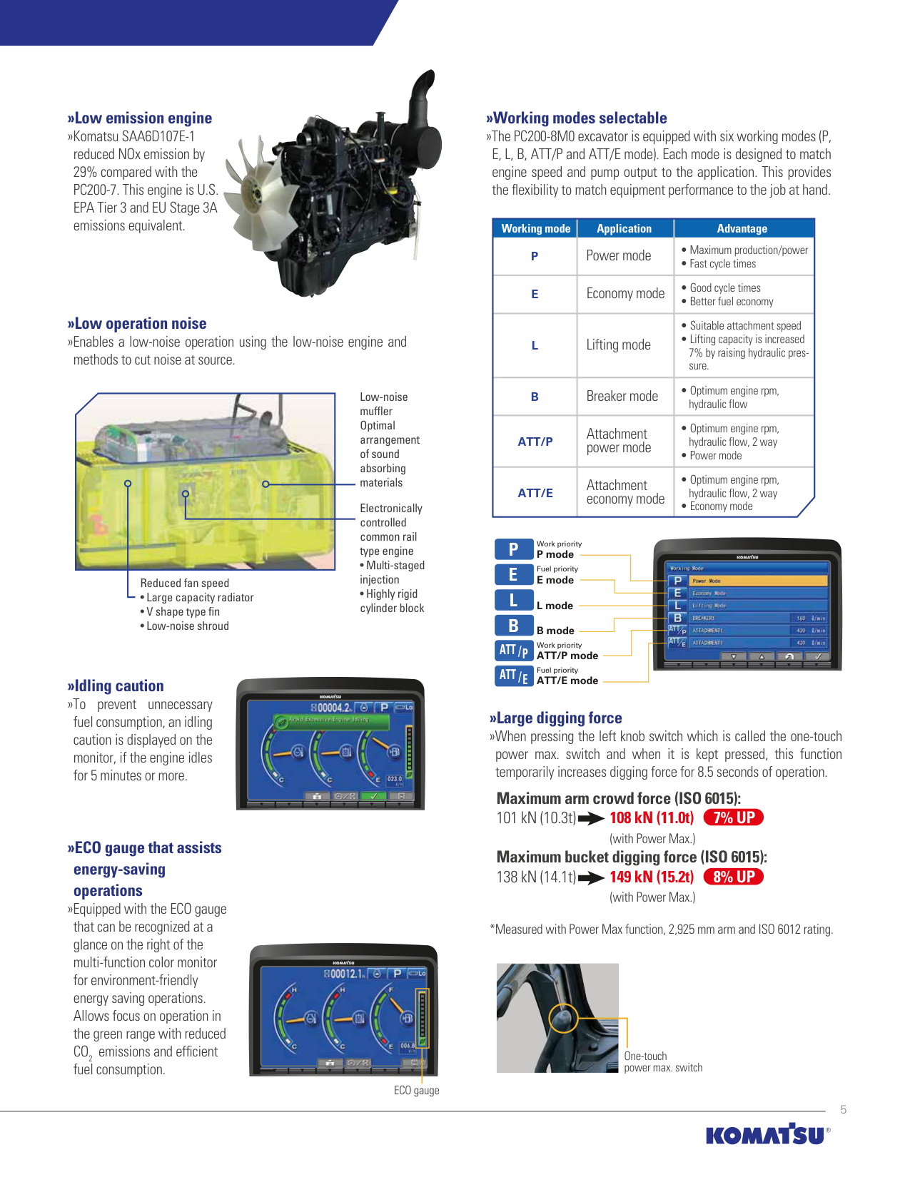
############# »Working modes selectable
############# »Low emission engine »Komatsu SAA6D107E-1
»The PC200-8M0 excavator is equipped with six working modes (P, E, L, B, ATT/P and ATT/E mode). Each mode is designed to match engine speed and pump output to the application. This provides the flexibility to match equipment performance to the job at hand.
reduced NOx emission by 29% compared with the PC200-7. This engine is U.S. EPA Tier 3 and EU Stage 3A emissions equivalent.
|Working mode P|Application Power mode|Advantage
• Maximum production/power
• Fast cycle times
| |---|---|---| |E|Economy mode|• Good cycle times
• Better fuel economy
| |L|Lifting mode|• Suitable attachment speed
• Lifting capacity is increased 7% by raising hydraulic pressure.
| |B|Breaker mode|• Optimum engine rpm, hydraulic flow| |ATT/P|Attachment power mode|• Optimum engine rpm, hydraulic flow, 2 way
• Power mode
| |ATT/E|Attachment economy mode|• Optimum engine rpm, hydraulic flow, 2 way
• Economy mode
|
»Low operation noise »Enables a low-noise operation using the low-noise engine and
methods to cut noise at source.

Low-noise muffler Optimal arrangement of sound absorbing materials
Electronically controlled common rail type engine
############ P E L B
Work priority P mode Fuel priority E mode

Reduced fan speed
L mode B mode Work priority
ATT /P
ATT/P mode Fuel priority ATT/E mode
################### ATT /E
############# »Idling caution
»To prevent unnecessary fuel consumption, an idling caution is displayed on the monitor, if the engine idles for 5 minutes or more.

»Large digging force »When pressing the left knob switch which is called the one-touch
power max. switch and when it is kept pressed, this function temporarily increases digging force for 8.5 seconds of operation.
Maximum arm crowd force (ISO 6015): 101 kN (10.3t) 108 kN (11.0t) 7% UP
(with Power Max.) Maximum bucket digging force (ISO 6015): 138 kN (14.1t) 149 kN (15.2t) 8% UP
############# »ECO gauge that assists energy-saving operations
(with Power Max.)
»Equipped with the ECO gauge that can be recognized at a glance on the right of the multi-function color monitor for environment-friendly energy saving operations. Allows focus on operation in the green range with reduced CO2 emissions and efficient fuel consumption.
*Measured with Power Max function, 2,925 mm arm and ISO 6012 rating.


One-touch power max. switch
ECO gauge
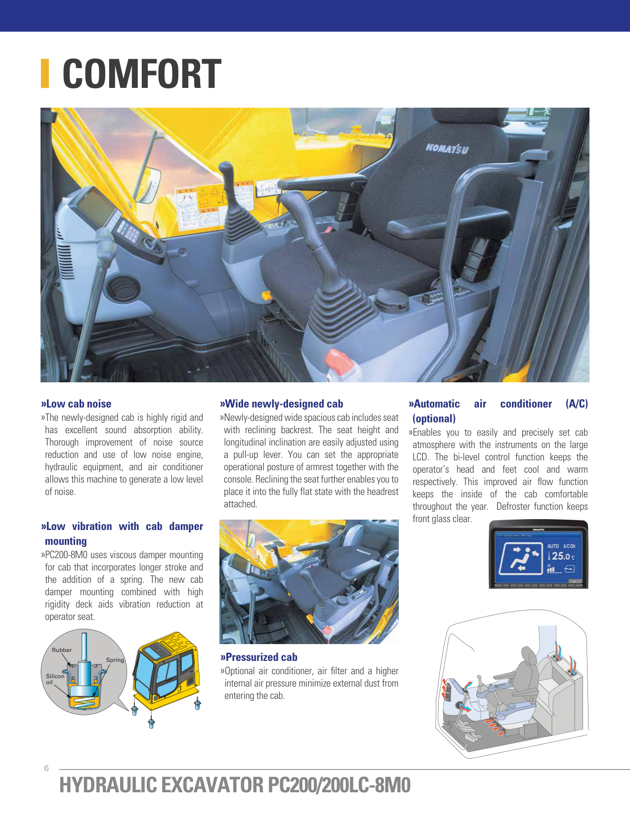
COMFORT

############ »Low cab noise
############ »Wide newly-designed cab
############ »Automatic air conditioner (A/C)
»The newly-designed cab is highly rigid and has excellent sound absorption ability. Thorough improvement of noise source reduction and use of low noise engine, hydraulic equipment, and air conditioner allows this machine to generate a low level of noise.
»Newly-designed wide spacious cab includes seat with reclining backrest. The seat height and longitudinal inclination are easily adjusted using a pull-up lever. You can set the appropriate operational posture of armrest together with the console. Reclining the seat further enables you to place it into the fully flat state with the headrest attached.
############# (optional)
»Enables you to easily and precisely set cab atmosphere with the instruments on the large LCD. The bi-level control function keeps the operator’s head and feet cool and warm respectively. This improved air flow function keeps the inside of the cab comfortable throughout the year. Defroster function keeps front glass clear.
############ »Low vibration with cab damper


############# mounting
»PC200-8M0 uses viscous damper mounting for cab that incorporates longer stroke and the addition of a spring. The new cab damper mounting combined with high rigidity deck aids vibration reduction at operator seat.
Rubber
»Pressurized cab »Optional air conditioner, air filter and a higher
Spring
Silicon oil
internal air pressure minimize external dust from entering the cab.
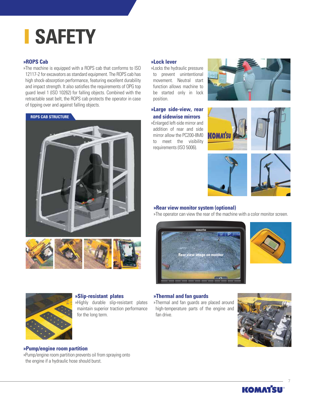
SAFETY
############# »ROPS Cab
»The machine is equipped with a ROPS cab that conforms to ISO 12117-2 for excavators as standard equipment. The ROPS cab has high shock-absorption performance, featuring excellent durability and impact strength. It also satisfies the requirements of OPG top guard level 1 (ISO 10262) for falling objects. Combined with the retractable seat belt, the ROPS cab protects the operator in case of tipping over and against falling objects.
ROPS CAB STRUCTURE


############# »Lock lever
»Locks the hydraulic pressure to prevent unintentional movement. Neutral start function allows machine to be started only in lock position.
»Large side-view, rear and sidewise mirrors »Enlarged left-side mirror and addition of rear and side mirror allow the PC200-8M0 to meet the visibility requirements (ISO 5006).


»Rear view monitor system (optional) »The operator can view the rear of the machine with a color monitor screen.


Rear view image on monitor
»Slip-resistant plates »Highly durable slip-resistant plates

maintain superior traction performance for the long term.
»Pump/engine room partition »Pump/engine room partition prevents oil from spraying onto
the engine if a hydraulic hose should burst.

»Thermal and fan guards »Thermal and fan guards are placed around
high-temperature parts of the engine and fan drive.

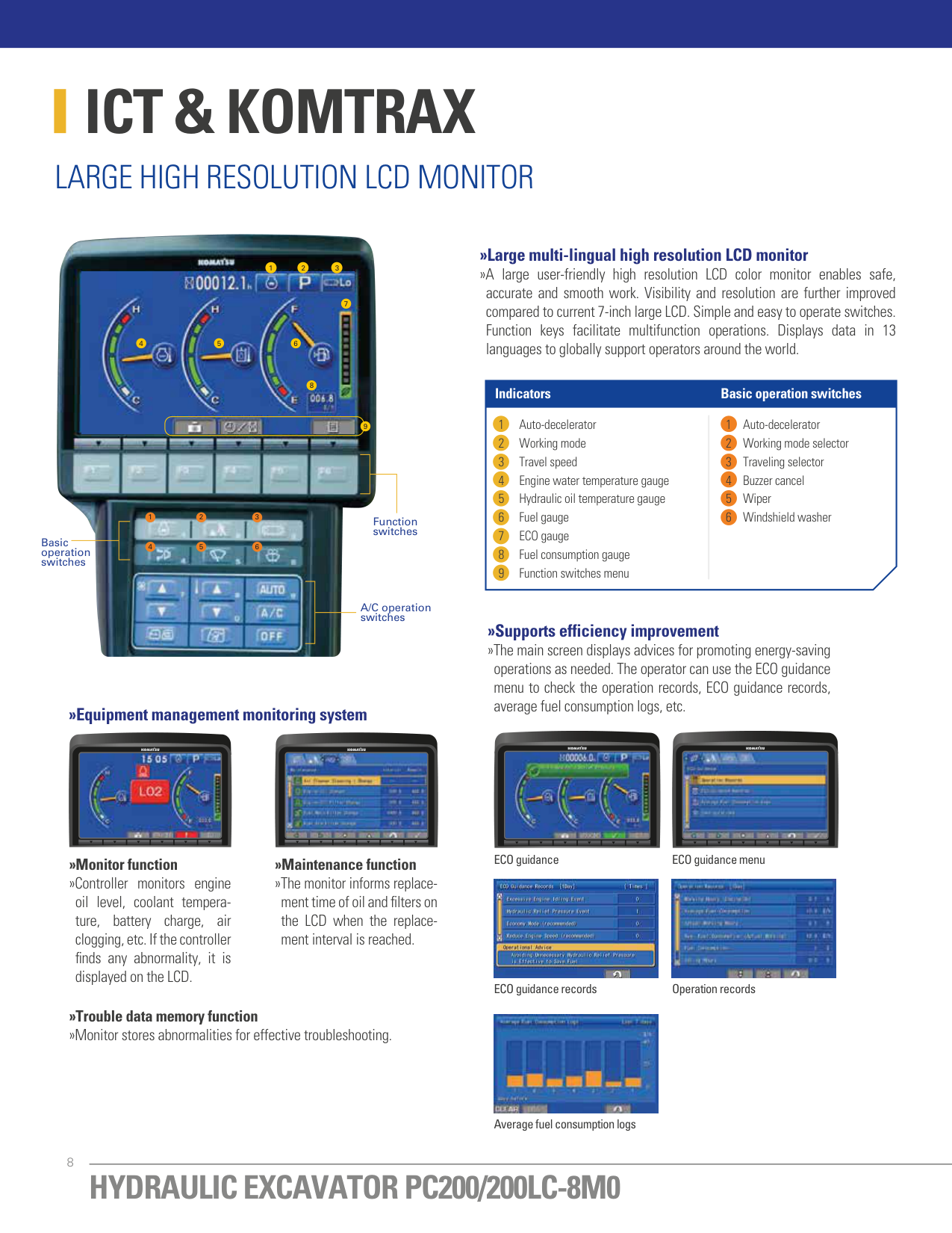
ICT & KOMTRAX
##### LARGE HIGH RESOLUTION LCD MONITOR

############# »Large multi-lingual high resolution LCD monitor
1 2 3
»A large user-friendly high resolution LCD color monitor enables safe, accurate and smooth work. Visibility and resolution are further improved compared to current 7-inch large LCD. Simple and easy to operate switches. Function keys facilitate multifunction operations. Displays data in 13 languages to globally support operators around the world.

7
4
5 6
8
#################### Indicators Basic operation switches
9
1 2 3
Function switches
| | | |---|---| | | |
Basic operation switches
4 5 6
A/C operation switches
############# »Supports efficiency improvement
»The main screen displays advices for promoting energy-saving operations as needed. The operator can use the ECO guidance menu to check the operation records, ECO guidance records, average fuel consumption logs, etc.
»Equipment management monitoring system


ECO guidance ECO guidance menu
################ »Monitor function
################ »Maintenance function
»Controller monitors engine oil level, coolant temperature, battery charge, air clogging, etc. If the controller finds any abnormality, it is displayed on the LCD.
»The monitor informs replacement time of oil and filters on the LCD when the replacement interval is reached.


Operation recordsECO guidance records
»Trouble data memory function »Monitor stores abnormalities for effective troubleshooting.

Average fuel consumption logs

SATELLITE MONITORING SYSTEM
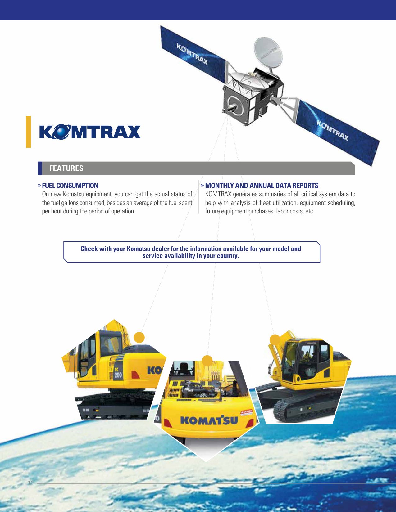
KOMTRAX is a revolutionary tracking system designed to save time and money. Nowadays, the equipment can be tracked anytime and anywhere. This valuable data, received via the KOMTRAX website, can be used to optimize planning of the movements and performance of the equipment.
############ FEATURES »
» »
############# EQUIPMENT KEY HOURS
############# WATER TEMPERATURE DAILY RECORD
############# LOCATION
Detailed information on key equipment hours such as excavation, moving, digging, alleviating and elevation. This can help to monitor and compare equipment performance, in addition to working hours and idle times.
KOMTRAX uses a satellite positioning network to inform the location of the equipment.
Constant record of the increase of engine water temperature with a daily report at the end of the day.
»
############# GEOFENCE
»
############# CAUTIONS
In partnership with your Komatsu Distributor, owners can create virtual fences (Geo) to receive alerts when the equipment enters or leaves the designated range for operations.
If a light turns on in the cab of the equipment it indicates that a problem occurs. From the website of the application you can review the reason for the problem, the time it occurred and a record number will be generated.
»
############# LOADING FREQUENCY

Information on the load factor of the equipment to know if it is performing a light, medium or heavy work.
»
############# SERVICE METER READING
»
############# ANTI-THEFT ENGINE LOCK
Daily report of the working hours of the equipment, which allows planning maintenance and replacement of components.
»
############# ABNORMALITY CODES
KOMTRAX has a system to lock and unlock the motor of the equipment, which will allow the operation only on preset days, hours and areas.
Abnormality codes are transmitted to the Komatsu Distributor for troubleshooting before technicians arrive at the workplace. An email notification is also sent with the code of what happened.
»
############# KOMTRAX OPERATION MAPS
In the operation maps you can check the times of the day when the equipment is in operation and if the workers are performing their duties in the stipulated times.
»
############# NOTICE OF MAINTENANCE REPLACEMENT
The system generates alerts to inform that the equipment requires change of elements like filters and oil.
»
FUEL MEASUREMENT LEVEL Shows the amount of fuel at the end of the working day.

############ FEATURES
############# » »
############# MONTHLY AND ANNUAL DATA REPORTS
############# FUEL CONSUMPTION
KOMTRAX generates summaries of all critical system data to help with analysis of fleet utilization, equipment scheduling, future equipment purchases, labor costs, etc.
On new Komatsu equipment, you can get the actual status of the fuel gallons consumed, besides an average of the fuel spent per hour during the period of operation.
Check with your Komatsu dealer for the information available for your model and service availability in your country.


MAINTENANCE
############# »Side-by-side cooling
»Since radiator, aftercooler and oil cooler are arranged in parallel, it is easy to clean, remove and install them. Radiator, aftercooler, and oil cooler made of aluminum have high cooling efficiency and are easily recycled.

############# »Equipped with the fuel pre-filter (with water separator)
»Removes water and contaminants in the fuel to prevent fuel problems. (With built-in priming pump).

############# »Easy access to engine oil filter and fuel drain valve
»Engine oil filter and fuel drain valve are remote mounted to improve accessibility.


############# »Equipped with the drain valve as standard
»Prevents clothes and the ground from becoming contaminated due to oil leakage when replacing the engine oil.

############# »Washable cab floormat
############# »Large-capacity fuel tank and rustproof treatment
»The PC200-8M0’s cab floormat is easy to keep clean. The gently inclined surface has a flanged floormat and drainage holes to facilitate runoff.
»400-liter high-capacity fuel tank. Effective corrosion resistance using rust-proof treatment.

»Sloping track frame »Prevents dirt and sand from accumulating and
allows easy mud removal.
############# »Gas assisted engine hood damper cylinders
»The engine hood can be easily opened and closed with the assistance of the gas assisted engine hood damper cylinders.

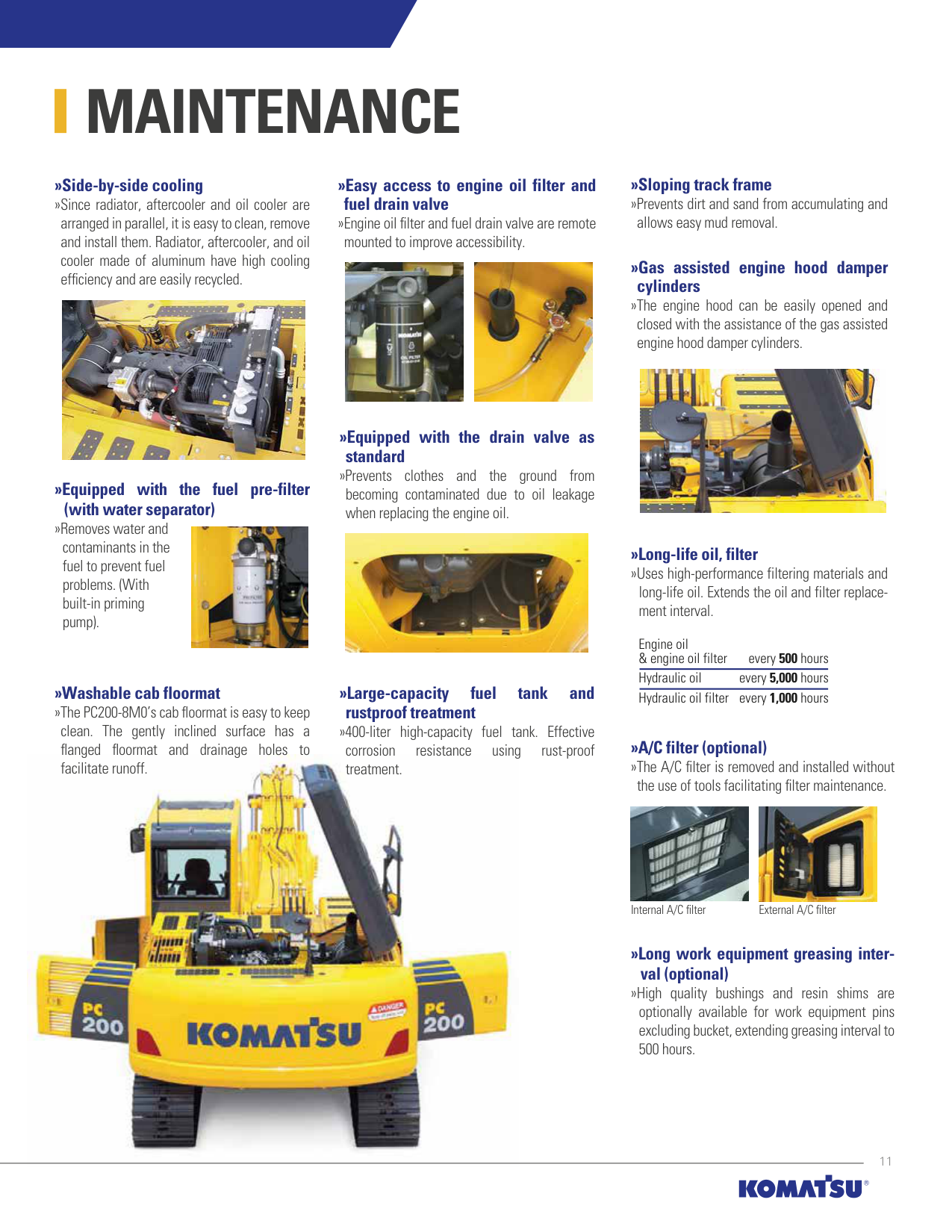
»Long-life oil, filter »Uses high-performance filtering materials and
long-life oil. Extends the oil and filter replacement interval.
Engine oil & engine oil filter every 500 hours Hydraulic oil every 5,000 hours Hydraulic oil filter every 1,000 hours
»A/C filter (optional) »The A/C filter is removed and installed without the use of tools facilitating filter maintenance.


Internal A/C filter External A/C filter
############# »Long work equipment greasing interval (optional)
»High quality bushings and resin shims are optionally available for work equipment pins excluding bucket, extending greasing interval to 500 hours.
RELIABILITY


»Sturdy frame structure »The revolving frame, center frame and undercarriage are designed by
############# »High rigidity work equipment
»Boom and arms are constructed of thick plates of high tensile strength steel. In addition, these structures are designed with large cross-sectional areas and generous use of castings. The result is working attachments that exhibit long term durability and high resistance to bending and torsional stress.
using the most advanced three-dimensional CAD and Finite Element Method (FEM) analysis technology.
»Reliable components »All of the major machine components, such as engine, hydraulic pumps,
»Highly reliable electronic devices »Exclusively designed electronic devices have passed severe testing.
hydraulic motors and control valves are exclusively designed and manufactured by Komatsu.

»Track link with strut »PC200-8M0 uses track links with strut, providing superb durability.
»Grease sealed track »PC200-8M0 uses grease sealed tracks for extended undercarriage life.

Grease Strut
OPTIONS
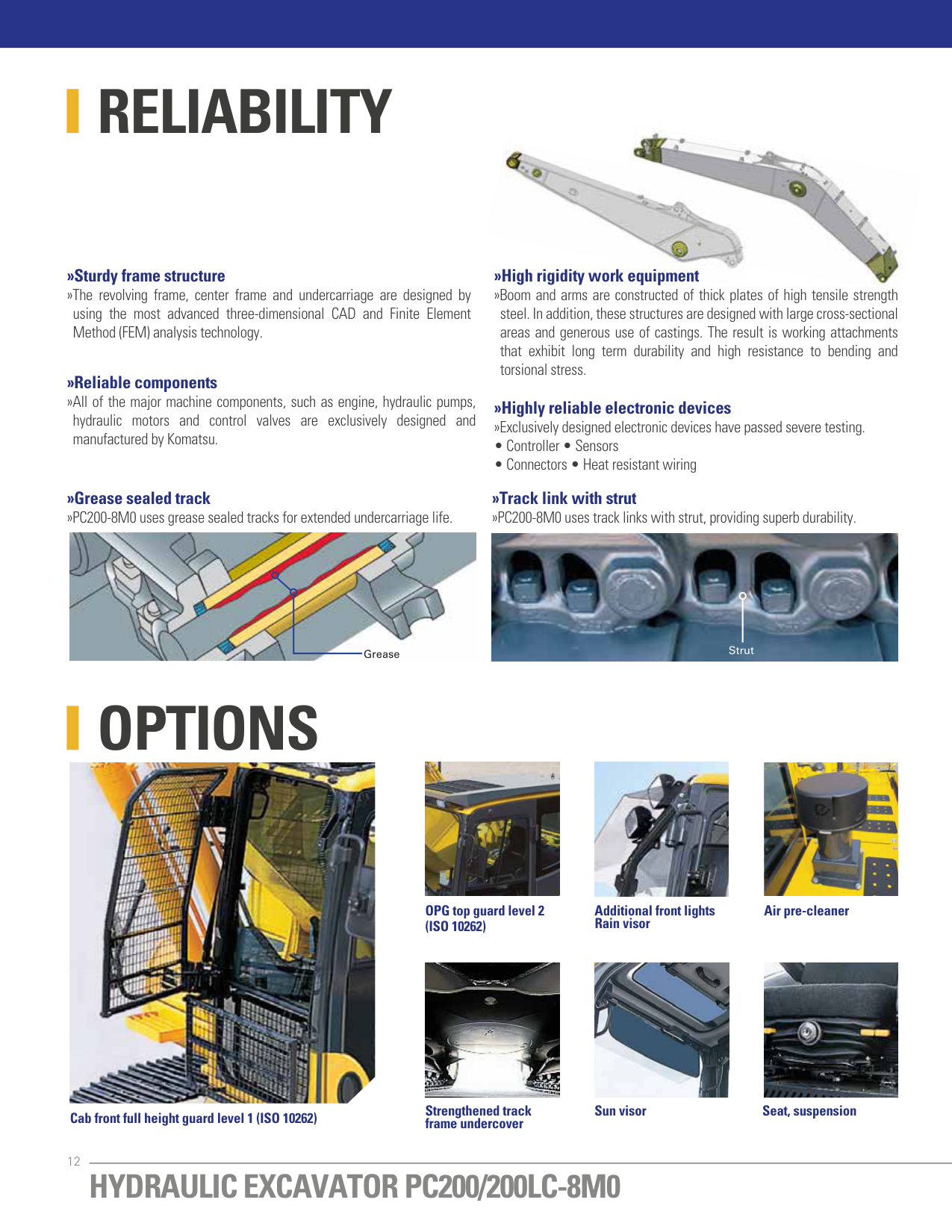


OPG top guard level 2 (ISO 10262)
Additional front lights Rain visor
Air pre-cleaner


Sun visorStrengthened track frame undercover
Seat, suspension
Cab front full height guard level 1 (ISO 10262)
KOMATSU BRAND BUCKET
############# »Komatsu brand bucket for general purpose with wide bucket width »Me bucket


#################### Category and Feature
Category Load / Wear / Soil (Application) Images


Load Machine power remains low during the majority of the work. No impact load. Wear Material is not abrasive. Soil Dirt, loam and clay.
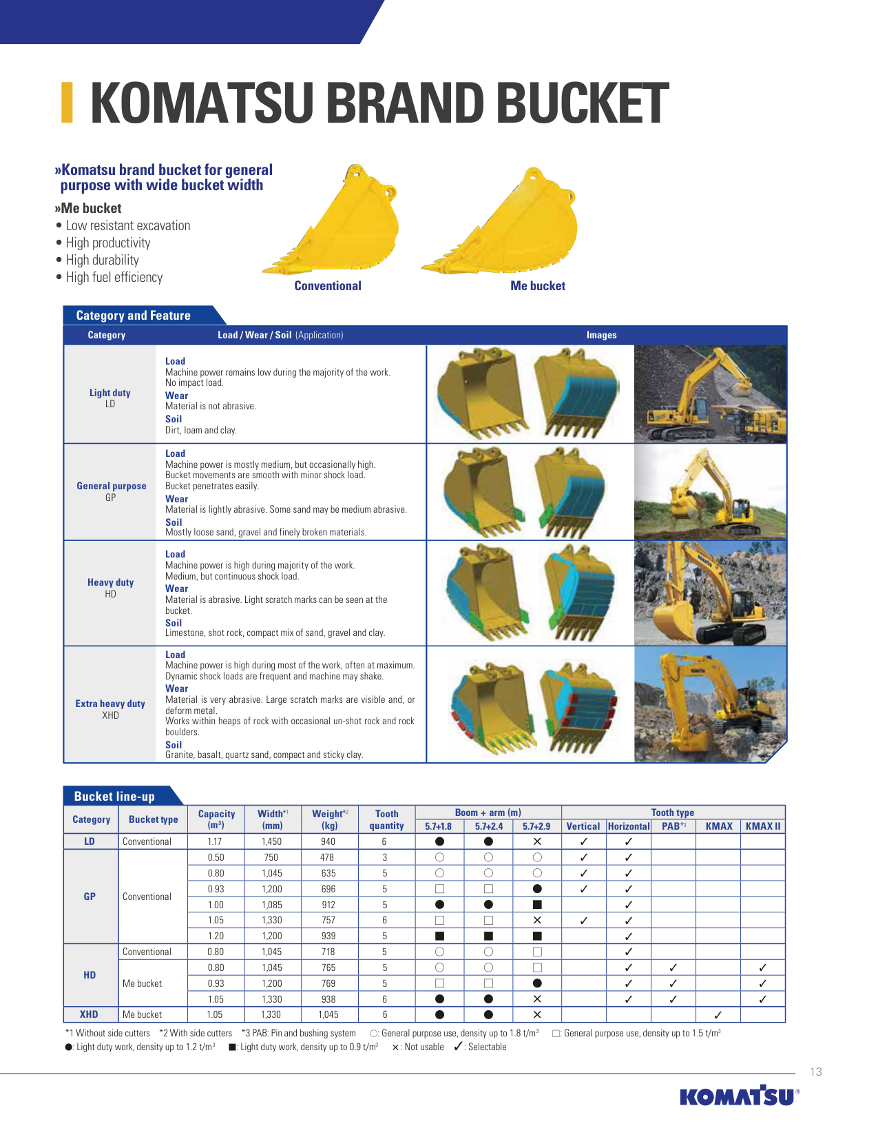
Light duty LD


Load Machine power is mostly medium, but occasionally high. Bucket movements are smooth with minor shock load. Bucket penetrates easily. Wear Material is lightly abrasive. Some sand may be medium abrasive. Soil Mostly loose sand, gravel and finely broken materials.
General purpose GP


Load Machine power is high during majority of the work. Medium, but continuous shock load. Wear Material is abrasive. Light scratch marks can be seen at the bucket. Soil Limestone, shot rock, compact mix of sand, gravel and clay.
Heavy duty HD

Load Machine power is high during most of the work, often at maximum. Dynamic shock loads are frequent and machine may shake. Wear Material is very abrasive. Large scratch marks are visible and, or deform metal. Works within heaps of rock with occasional un-shot rock and rock boulders. Soil Granite, basalt, quartz sand, compact and sticky clay.


Extra heavy duty XHD
#################### Bucket line-up
|Category|Bucket type|Capacity (m3)|Width*1 (mm)|Weight*2 (kg)|Tooth quantity|)m(mra+mooB|)m(mra+mooB|)m(mra+mooB|epythtooT|epythtooT|epythtooT|epythtooT|epythtooT| |---|---|---|---|---|---|---|---|---|---|---|---|---|---| |Category|Bucket type|Capacity (m3)|Width*1 (mm)|Weight*2 (kg)|Tooth quantity|5.7+1.8|5.7+2.4|5.7+2.9|Vertical|Horizontal|PAB*3|KMAX|KMAX II| |LD|Conventional|1.17|1,450|940|6| | | |✓|✓| | | | |GP|Conventional|0.50|750|478|3| | | |✓|✓| | | | |GP|Conventional|0.80|1,045|635|5| | | |✓|✓| | | | |GP|Conventional|0.93|1,200|696|5| | | |✓|✓| | | | |GP|Conventional|1.00|1,085|912|5| | | | |✓| | | | |GP|Conventional|1.05|1,330|757|6| | | |✓|✓| | | | |GP|Conventional|1.20|1,200|939|5| | | | |✓| | | | |HD|Conventional|0.80|1,045|718|5| | | | |✓| | | | |HD|Me bucket|0.80|1,045|765|5| | | | |✓|✓| |✓| |HD|Me bucket|0.93|1,200|769|5| | | | |✓|✓| |✓| |HD|Me bucket|1.05|1,330|938|6| | | | |✓|✓| |✓| |XHD|Me bucket|1.05|1,330|1,045|6| | | | | | |✓| |
*1 Without side cutters *2 With side cutters *3 PAB: Pin and bushing system : General purpose use, density up to 1.8 t/m3 : General purpose use, density up to 1.5 t/m3
: Light duty work, density up to 1.2 t/m3 : Light duty work, density up to 0.9 t/m3 : Not usable ✓: Selectable
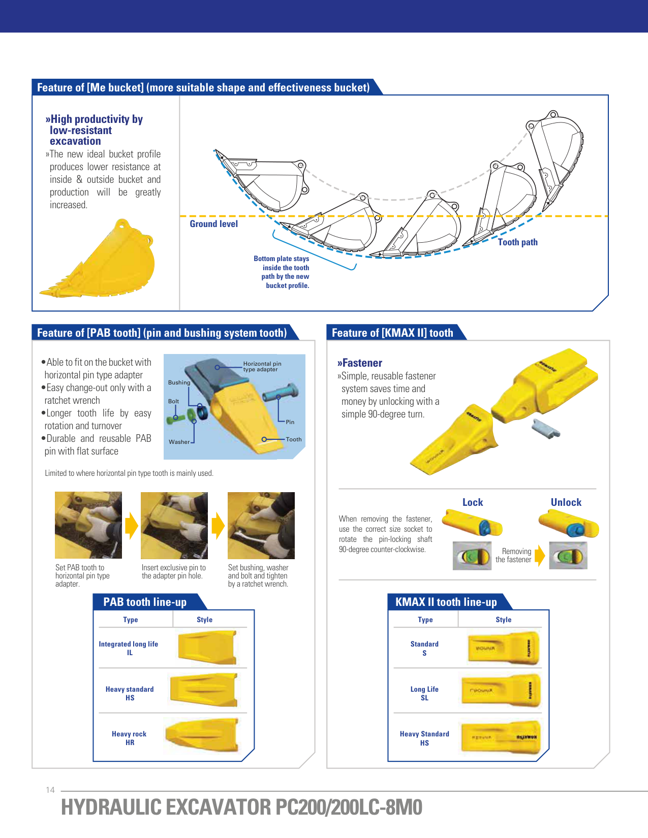
############# Feature of [Me bucket] (more suitable shape and effectiveness bucket)
|»High productivity by low-resistant excavation
»The new ideal bucket profile produces lower resistance at inside & outside bucket and production will be greatly increased.
| | |---|---| |»High productivity by low-resistant excavation
»The new ideal bucket profile produces lower resistance at inside & outside bucket and production will be greatly increased.
|Bottom plate stays inside the tooth path by the new
bucket profile.
Ground level
Tooth path|
############# Feature of [PAB tooth] (pin and bushing system tooth) Feature of [KMAX II] tooth


»Fastener »Simple, reusable fastener
Horizontal pin type adapter
Bushing
system saves time and money by unlocking with a simple 90-degree turn.
Bolt


Pin
ToothWasher
Limited to where horizontal pin type tooth is mainly used.


################ Lock Unlock


When removing the fastener, use the correct size socket to rotate the pin-locking shaft 90-degree counter-clockwise.
Removing the fastener
Set PAB tooth to horizontal pin type adapter.
Insert exclusive pin to the adapter pin hole.
Set bushing, washer and bolt and tighten by a ratchet wrench.
############# PAB tooth line-up
############# KMAX II tooth line-up
Type Style
Type Style


Integrated long life IL
Standard S


Heavy standard HS
Long Life SL


Heavy rock HR
Heavy Standard HS
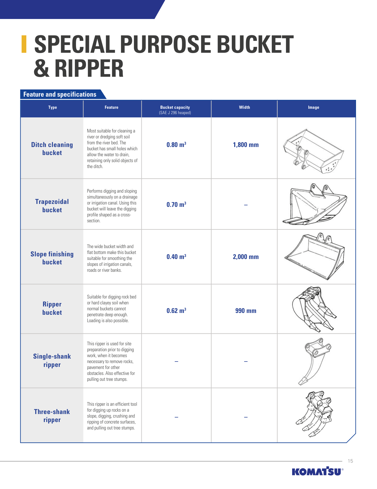
SPECIAL PURPOSE BUCKET & RIPPER
Feature and specifications
######################### Type Feature Bucket capacity Width Image
(SAE J 296 heaped)
Ditch cleaning bucket
Most suitable for cleaning a river or dredging soft soil from the river bed. The bucket has small holes which allow the water to drain, retaining only solid objects of the ditch.
Trapezoidal bucket
Performs digging and sloping simultaneously on a drainage or irrigation canal. Using this bucket will leave the digging profile shaped as a crosssection.
Slope finishing bucket
The wide bucket width and flat bottom make this bucket suitable for smoothing the slopes of irrigation canals, roads or river banks.
Ripper bucket
Suitable for digging rock bed or hard clayey soil when normal buckets cannot penetrate deep enough. Loading is also possible.
Single-shank ripper
This ripper is used for site preparation prior to digging work, when it becomes necessary to remove rocks, pavement for other obstacles. Also effective for pulling out tree stumps.
Three-shank ripper
This ripper is an efficient tool for digging up rocks on a slope, digging, crushing and ripping of concrete surfaces, and pulling out tree stumps.
0.80 m3 1,800 mm
0.70 m3 –
0.40 m3 2,000 mm
0.62 m3 990 mm


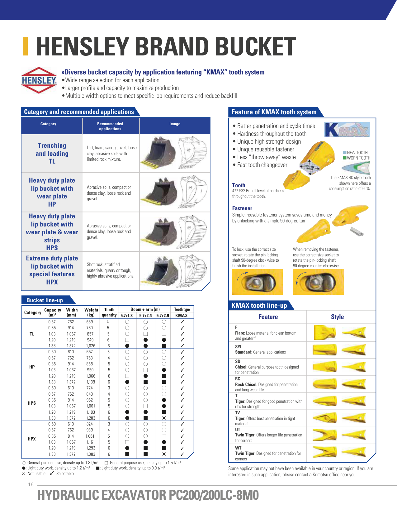
HENSLEY BRAND BUCKET

############# »Diverse bucket capacity by application featuring “KMAX” tooth system
############### Category and recommended applications
Category Recommended Image applications


############### Trenching and loading TL
Dirt, loam, sand, gravel, loose clay, abrasive soils with limited rock mixture.

############### Heavy duty plate lip bucket with wear plate HP

Abrasive soils, compact or dense clay, loose rock and gravel.
############### Heavy duty plate lip bucket with wear plate & wear strips HPS


Abrasive soils, compact or dense clay, loose rock and gravel.
############### Extreme duty plate lip bucket with special features HPX


Shot rock, stratified materials, quarry or tough, highly abrasive applications.
#################### Bucket line-up
|Category|Capacity (m)3|Width (mm)|Weight (kg)|Tooth quantity|Boom + arm (m)|Boom + arm (m)|Boom + arm (m)|Tooth type| |---|---|---|---|---|---|---|---|---| |Category|Capacity (m)3|Width (mm)|Weight (kg)|Tooth quantity|5.7+1.8|5.7+2.4|5.7+2.9|KMAX| |TL|0.67 0.85 1.03 1.20 1.38|762 914 1,067 1,219 1,372|689 780 857 949 1,026|4
5
5
6
6
| | | |✓ ✓ ✓ ✓ ✓| |HP|0.50 0.67 0.85 1.03 1.20 1.38|610 762 914 1,067 1,219 1,372|652 763 868 950 1,066 1,139|3
4
5
5
6
6
| | | |✓ ✓ ✓ ✓ ✓ ✓| |HPS|0.50 0.67 0.85 1.03 1.20 1.38|610 762 914 1,067 1,219 1,372|724 840 962 1,061 1,193 1,283|3
4
5
5
6
6
| | | |✓ ✓ ✓ ✓ ✓ ✓| |HPX|0.50 0.67 0.85 1.03 1.20 1.38|610 762 914 1,067 1,219 1,372|824 939 1,061 1,161 1,293 1,383|3
4
5
5
6
6
| | | |✓ ✓ ✓ ✓ ✓ ✓|
: General purpose use, density up to 1.8 t/m3 : General purpose use, density up to 1.5 t/m3 : Light duty work, density up to 1.2 t/m3 : Light duty work, density: up to 0.9 t/m3
: Not usable ✓: Selectable
Feature of KMAX tooth system
|Tooth
Fastener Simple, reusable fastener system saves time and money by unlocking with a simple 90-degree turn.
• Better penetration and cycle times
• Hardness throughout the tooth
• Unique high strength design
• Unique reusable fastener
• Less “throw away” waste
• Fast tooth changeover
477-532 Brinell level of hardness throughout the tooth.
The KMAX RC style tooth shown here offers a consumption ratio of 60%.
NEW TOOTH WORN TOOTH
To lock, use the correct size socket, rotate the pin locking shaft 90-degree clock wise to finish the installation.
When removing the fastener, use the correct size socket to rotate the pin-locking shaft 90-degree counter-clockwise.
KMAX tooth line-up


| |---|---| |Feature|Style| |F Flare: Loose material for clean bottom and greater fill|
| |SYL Standard: General applications|
| |SD Chisel: General purpose tooth designed for penetration|
| |RC Rock Chisel: Designed for penetration and long wear life|
| |T Tiger: Designed for good penetration with ribs for strength|
| |TV Tiger: Offers best penetration in tight material|
| |UT Twin Tiger: Offers longer life penetration for corners|
| |WT Twin Tiger: Designed for penetration for corners|
|
Some application may not have been available in your country or region. If you are interested in such application, please contact a Komatsu office near you.
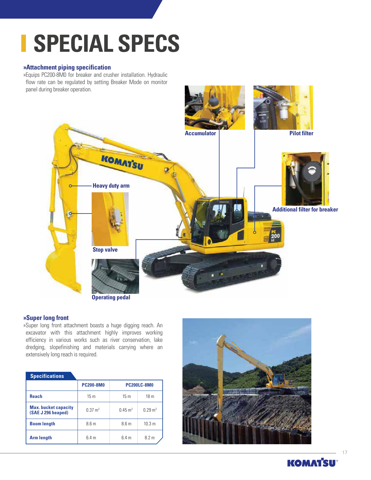
SPECIAL SPECS
»Attachment piping specification »Equips PC200-8M0 for breaker and crusher installation. Hydraulic
flow rate can be regulated by setting Breaker Mode on monitor panel during breaker operation.


Accumulator
Pilot filter

Heavy duty arm

Additional filter for breaker
Stop valve

Operating pedal
############# »Super long front
»Super long front attachment boasts a huge digging reach. An excavator with this attachment highly improves working efficiency in various works such as river conservation, lake dredging, slopefinishing and materials carrying where an extensively long reach is required.
Specifications
| |PC200-8M0|PC200LC-8M0|PC200LC-8M0| |---|---|---|---| |Reach|15 m|15 m|18 m| |Max. bucket capacity (SAE J 296 heaped)|0.37 m3|0.45 m3|0.29 m3| |Boom length|8.6 m|8.6 m|10.3 m| |Arm length|6.4 m|6.4 m|8.2 m|


ATTACHMENT
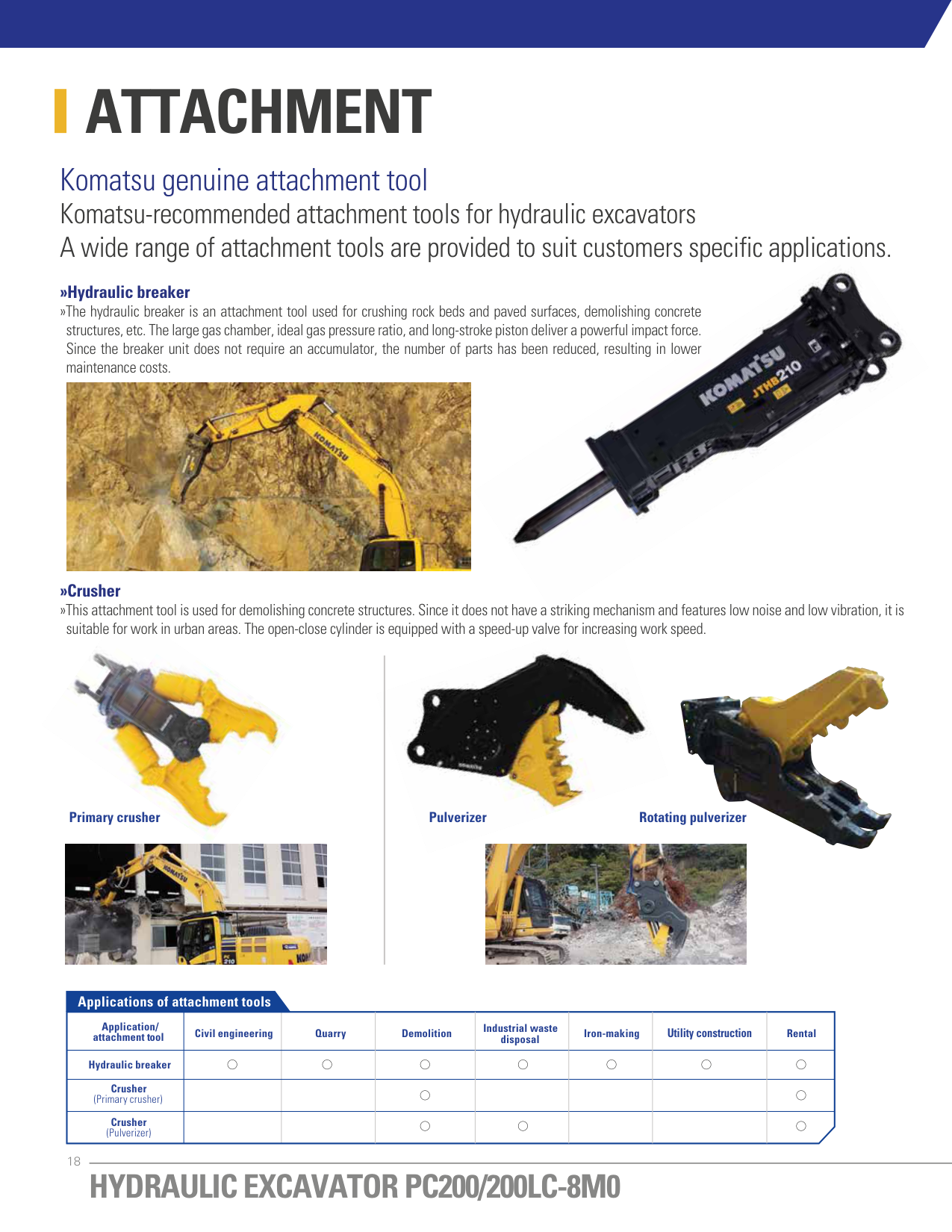
####### Komatsu genuine attachment tool Komatsu-recommended attachment tools for hydraulic excavators A wide range of attachment tools are provided to suit customers specific applications. »Hydraulic breaker

»The hydraulic breaker is an attachment tool used for crushing rock beds and paved surfaces, demolishing concrete structures, etc. The large gas chamber, ideal gas pressure ratio, and long-stroke piston deliver a powerful impact force. Since the breaker unit does not require an accumulator, the number of parts has been reduced, resulting in lower maintenance costs.

»Crusher »This attachment tool is used for demolishing concrete structures. Since it does not have a striking mechanism and features low noise and low vibration, it is


suitable for work in urban areas. The open-close cylinder is equipped with a speed-up valve for increasing work speed.

Primary crusher Rotating pulverizerPulverizer


Applications of attachment tools
|Application/ attachment tool|Civil engineering|Quarry|Demolition|Industrial waste disposal|Iron-making|Utility construction|Rental| |---|---|---|---|---|---|---|---| |Hydraulic breaker| | | | | | | | |Crusher (Primary crusher)| | | | | | | | |Crusher (Pulverizer)| | | | | | | |
KOMATSU TOTAL SUPPORT
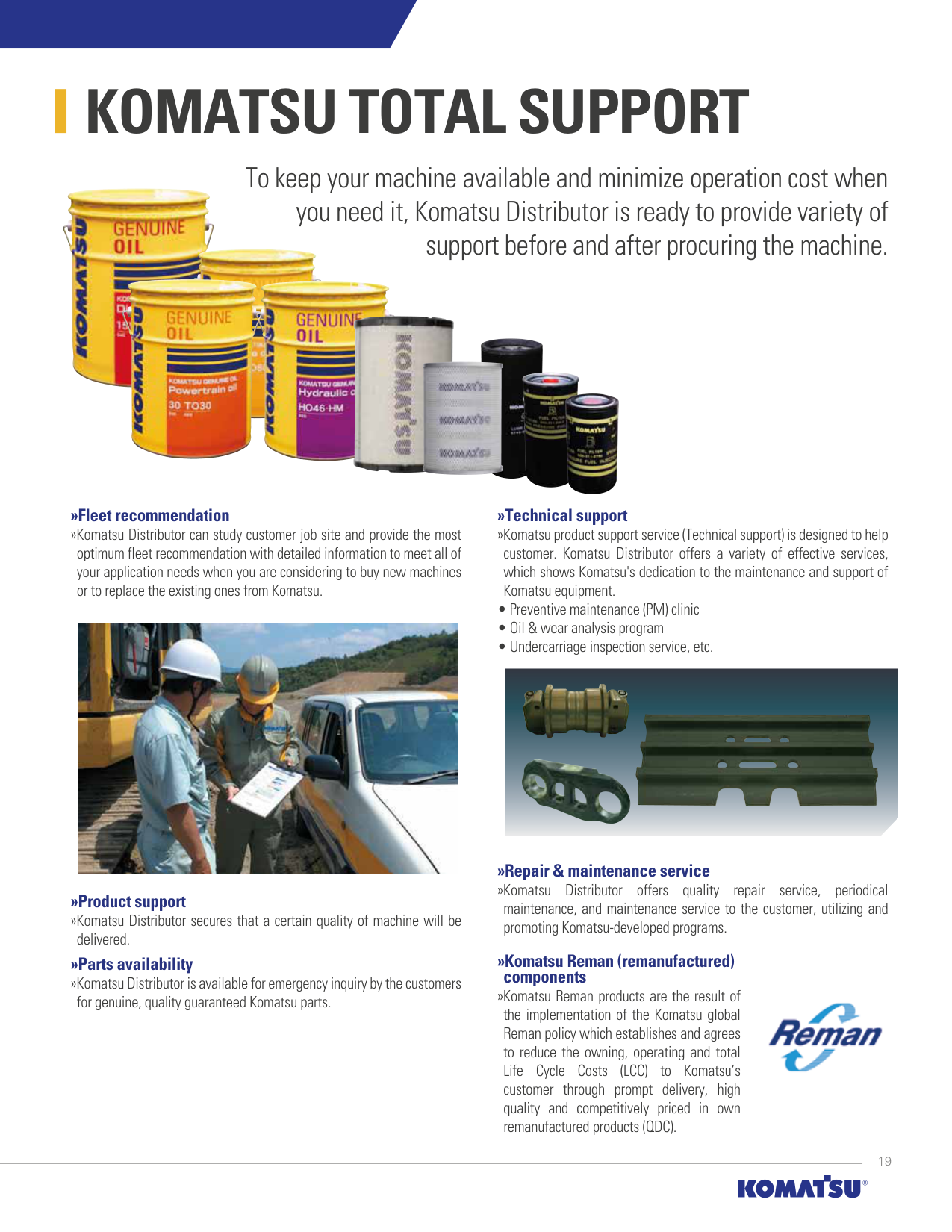
######### To keep your machine available and minimize operation cost when you need it, Komatsu Distributor is ready to provide variety of support before and after procuring the machine.


############# »Fleet recommendation
############# »Technical support
»Komatsu Distributor can study customer job site and provide the most optimum fleet recommendation with detailed information to meet all of your application needs when you are considering to buy new machines or to replace the existing ones from Komatsu.
»Komatsu product support service (Technical support) is designed to help customer. Komatsu Distributor offers a variety of effective services, which shows Komatsu's dedication to the maintenance and support of Komatsu equipment.


»Repair & maintenance service »Komatsu Distributor offers quality repair service, periodical
»Product support »Komatsu Distributor secures that a certain quality of machine will be
maintenance, and maintenance service to the customer, utilizing and promoting Komatsu-developed programs.
delivered.
############# »Komatsu Reman (remanufactured) components
»Parts availability »Komatsu Distributor is available for emergency inquiry by the customers
»Komatsu Reman products are the result of the implementation of the Komatsu global Reman policy which establishes and agrees to reduce the owning, operating and total Life Cycle Costs (LCC) to Komatsu’s customer through prompt delivery, high quality and competitively priced in own remanufactured products (QDC).

for genuine, quality guaranteed Komatsu parts.
SPECIFICATIONS
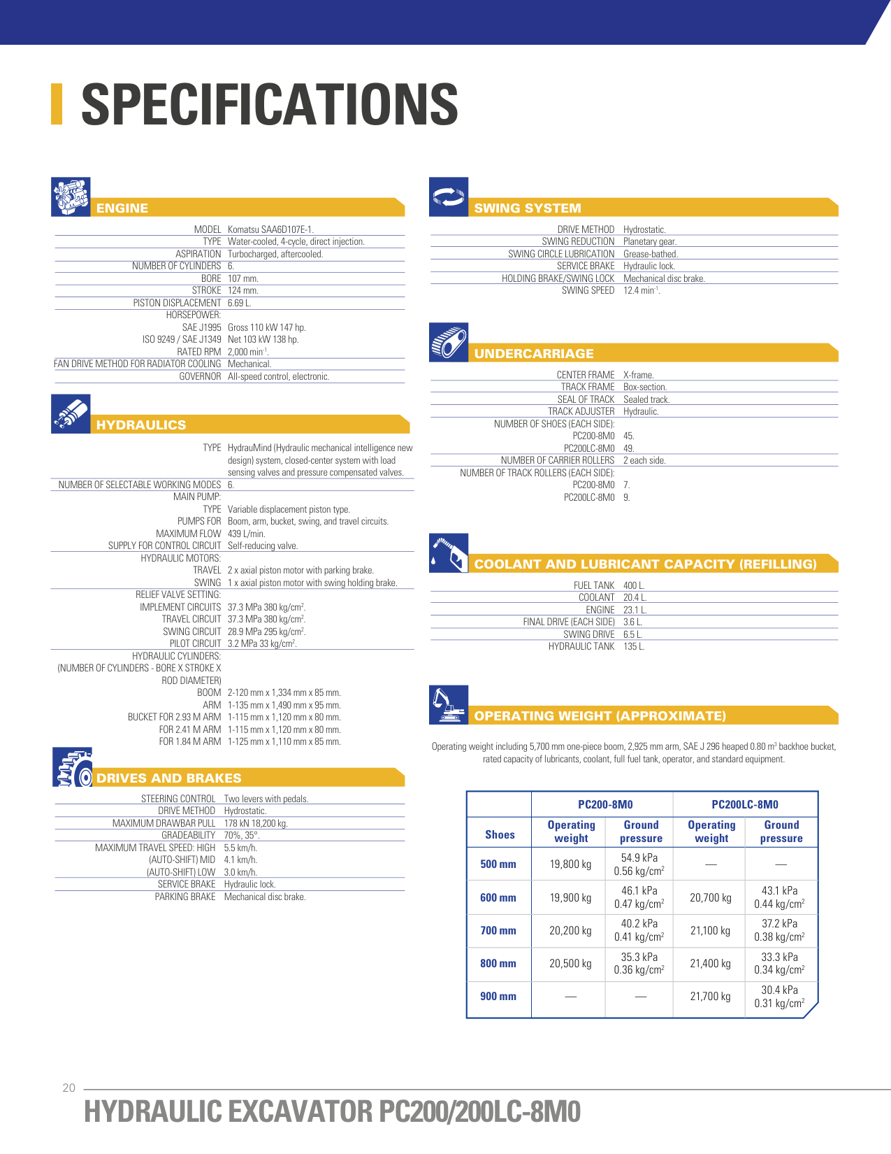
ENGINE
MODEL TYPE
Komatsu SAA6D107E-1. Water-cooled, 4-cycle, direct injection. Turbocharged, aftercooled. 6. 107 mm. 124 mm. 6.69 L.
ASPIRATION NUMBER OF CYLINDERS
BORE STROKE
PISTON DISPLACEMENT HORSEPOWER:
SAE J1995 ISO 9249 / SAE J1349
Gross 110 kW 147 hp. Net 103 kW 138 hp. 2,000 min-1. Mechanical. All-speed control, electronic.
RATED RPM FAN DRIVE METHOD FOR RADIATOR COOLING GOVERNOR
HYDRAULICS
TYPE
HydrauMind (Hydraulic mechanical intelligence new design) system, closed-center system with load sensing valves and pressure compensated valves. 6.
NUMBER OF SELECTABLE WORKING MODES MAIN PUMP: TYPE
Variable displacement piston type. Boom, arm, bucket, swing, and travel circuits. 439 L/min. Self-reducing valve.
PUMPS FOR MAXIMUM FLOW
SUPPLY FOR CONTROL CIRCUIT
HYDRAULIC MOTORS: TRAVEL SWING
2 x axial piston motor with parking brake. 1 x axial piston motor with swing holding brake.
RELIEF VALVE SETTING:
IMPLEMENT CIRCUITS TRAVEL CIRCUIT SWING CIRCUIT
37.3 MPa 380 kg/cm2. 37.3 MPa 380 kg/cm2. 28.9 MPa 295 kg/cm2. 3.2 MPa 33 kg/cm2.
PILOT CIRCUIT HYDRAULIC CYLINDERS:
(NUMBER OF CYLINDERS - BORE X STROKE X ROD DIAMETER) BOOM ARM
2-120 mm x 1,334 mm x 85 mm. 1-135 mm x 1,490 mm x 95 mm. 1-115 mm x 1,120 mm x 80 mm. 1-115 mm x 1,120 mm x 80 mm. 1-125 mm x 1,110 mm x 85 mm.
BUCKET FOR 2.93 M ARM FOR 2.41 M ARM FOR 1.84 M ARM
DRIVES AND BRAKES
STEERING CONTROL
Two levers with pedals. Hydrostatic. 178 kN 18,200 kg. 70%, 35°. 5.5 km/h. 4.1 km/h. 3.0 km/h. Hydraulic lock. Mechanical disc brake.
DRIVE METHOD MAXIMUM DRAWBAR PULL
GRADEABILITY MAXIMUM TRAVEL SPEED: HIGH
(AUTO-SHIFT) MID (AUTO-SHIFT) LOW
SERVICE BRAKE PARKING BRAKE
##################### SWING SYSTEM
Hydrostatic. Planetary gear. Grease-bathed. Hydraulic lock. Mechanical disc brake. 12.4 min-1.
DRIVE METHOD SWING REDUCTION
SWING CIRCLE LUBRICATION
SERVICE BRAKE HOLDING BRAKE/SWING LOCK
SWING SPEED
UNDERCARRIAGE
X-frame. Box-section. Sealed track. Hydraulic.
CENTER FRAME TRACK FRAME
SEAL OF TRACK TRACK ADJUSTER
NUMBER OF SHOES (EACH SIDE):
PC200-8M0 PC200LC-8M0
NUMBER OF CARRIER ROLLERS NUMBER OF TRACK ROLLERS (EACH SIDE):
PC200-8M0 PC200LC-8M0
COOLANT AND LUBRICANT CAPACITY (REFILLING)
400 L. 20.4 L. 23.1 L. 3.6 L. 6.5 L. 135 L.
FUEL TANK COOLANT
ENGINE FINAL DRIVE (EACH SIDE)
SWING DRIVE HYDRAULIC TANK
OPERATING WEIGHT (APPROXIMATE)
Operating weight including 5,700 mm one-piece boom, 2,925 mm arm, SAE J 296 heaped 0.80 m3 backhoe bucket, rated capacity of lubricants, coolant, full fuel tank, operator, and standard equipment.
| |PC200-8M0|PC200-8M0|PC200LC-8M0|PC200LC-8M0| |---|---|---|---|---| |Shoes|Operating weight|Ground pressure|Operating weight|Ground pressure| |500 mm|19,800 kg|54.9 kPa 0.56 kg/cm2|—|—| |600 mm|19,900 kg|46.1 kPa 0.47 kg/cm2|20,700 kg|43.1 kPa 0.44 kg/cm2| |700 mm|20,200 kg|40.2 kPa 0.41 kg/cm2|21,100 kg|37.2 kPa 0.38 kg/cm2| |800 mm|20,500 kg|35.3 kPa 0.36 kg/cm2|21,400 kg|33.3 kPa 0.34 kg/cm2| |900 mm| | |21,700 kg|30.4 kPa 0.31 kg/cm2|
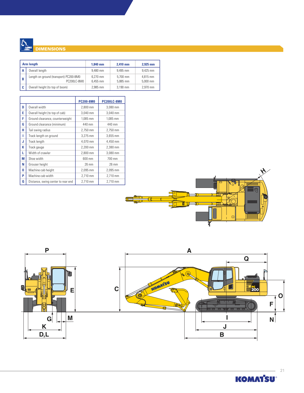
DIMENSIONS
|Arm length|Arm length|1,840 mm|2,410 mm|2,925 mm| |---|---|---|---|---| |A|Overall length|9,480 mm|9,495 mm|9,425 mm| |B|Length on ground (transport):PC200-8M0 PC200LC-8M0|6,270 mm 6,455 mm|5,700 mm 5,885 mm|4,815 mm
5,000 mm
| |C|Overall height (to top of boom)|2,985 mm|3,190 mm|2,970 mm|
| | |PC200-8M0|PC200LC-8M0| |---|---|---|---| |D|Overall width|2,800 mm|3,080 mm| |E|Overall height (to top of cab)|3,040 mm|3,040 mm| |F|Ground clearance, counterweight|1,085 mm|1,085 mm| |G|Ground clearance (minimum)|440 mm|440 mm| |H|Tail swing radius|2,750 mm|2,750 mm| |I|Track length on ground|3,275 mm|3,655 mm| |J|Track length|4,070 mm|4,450 mm| |K|Track gauge|2,200 mm|2,380 mm| |L|Width of crawler|2,800 mm|3,080 mm| |M|Shoe width|600 mm|700 mm| |N|Grouser height|26 mm|26 mm|
|O|Machine cab height|2,095 mm|2,095 mm| |P|Machine cab width|2,710 mm|2,710 mm| |Q|Distance, swing center to rear end|2,710 mm|2,710 mm|
H
P
A
| | | |---|---| | | |
Q
C
E
F
O
MG
K
D,L
B
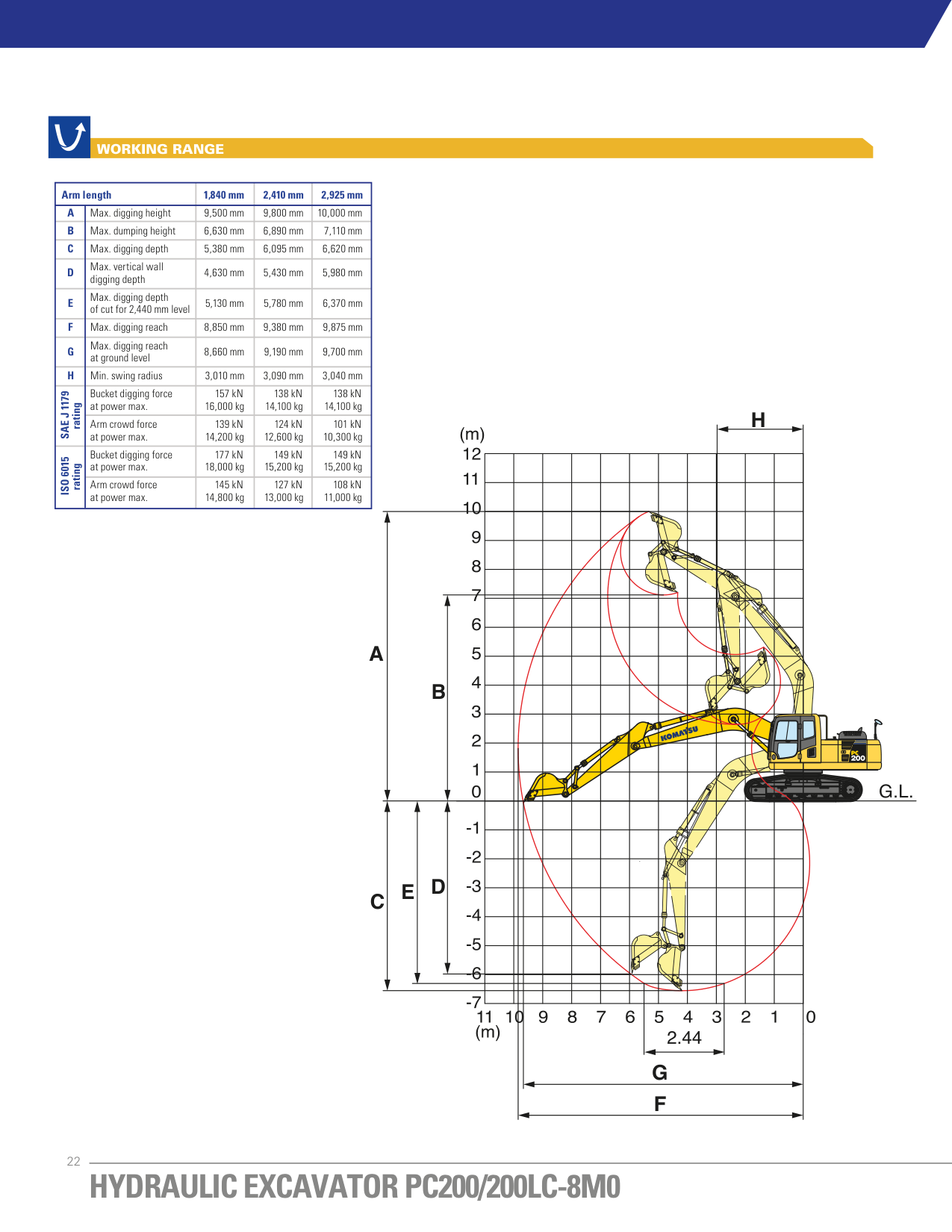
WORKING RANGE
|Arm length|Arm length|1,840 mm|2,410 mm|2,925 mm| |---|---|---|---|---| |A|Max. digging height|9,500 mm|9,800 mm|10,000 mm| |B|Max. dumping height|6,630 mm|6,890 mm|7,110 mm| |C|Max. digging depth|5,380 mm|6,095 mm|6,620 mm| |D|Max. vertical wall digging depth|4,630 mm|5,430 mm|5,980 mm| |E|Max. digging depth of cut for 2,440 mm level|5,130 mm|5,780 mm|6,370 mm| |F|Max. digging reach|8,850 mm|9,380 mm|9,875 mm| |G|Max. digging reach at ground level|8,660 mm|9,190 mm|9,700 mm| |H|Min. swing radius|3,010 mm|3,090 mm|3,040 mm| |SAE J 1179
rating|Bucket digging force at power max.|157 kN 16,000 kg|138 kN 14,100 kg|138 kN 14,100 kg| |SAE J 1179
rating|Arm crowd force at power max.|139 kN 14,200 kg|124 kN 12,600 kg|101 kN 10,300 kg|

|ISO 6015
rating|Bucket digging force at power max.|177 kN 18,000 kg|149 kN 15,200 kg|149 kN 15,200 kg| |ISO 6015
rating|Arm crowd force at power max.|145 kN 14,800 kg|127 kN 13,000 kg|108 kN 11,000 kg|
########### H
########### A
########### B
########### C E D
B C
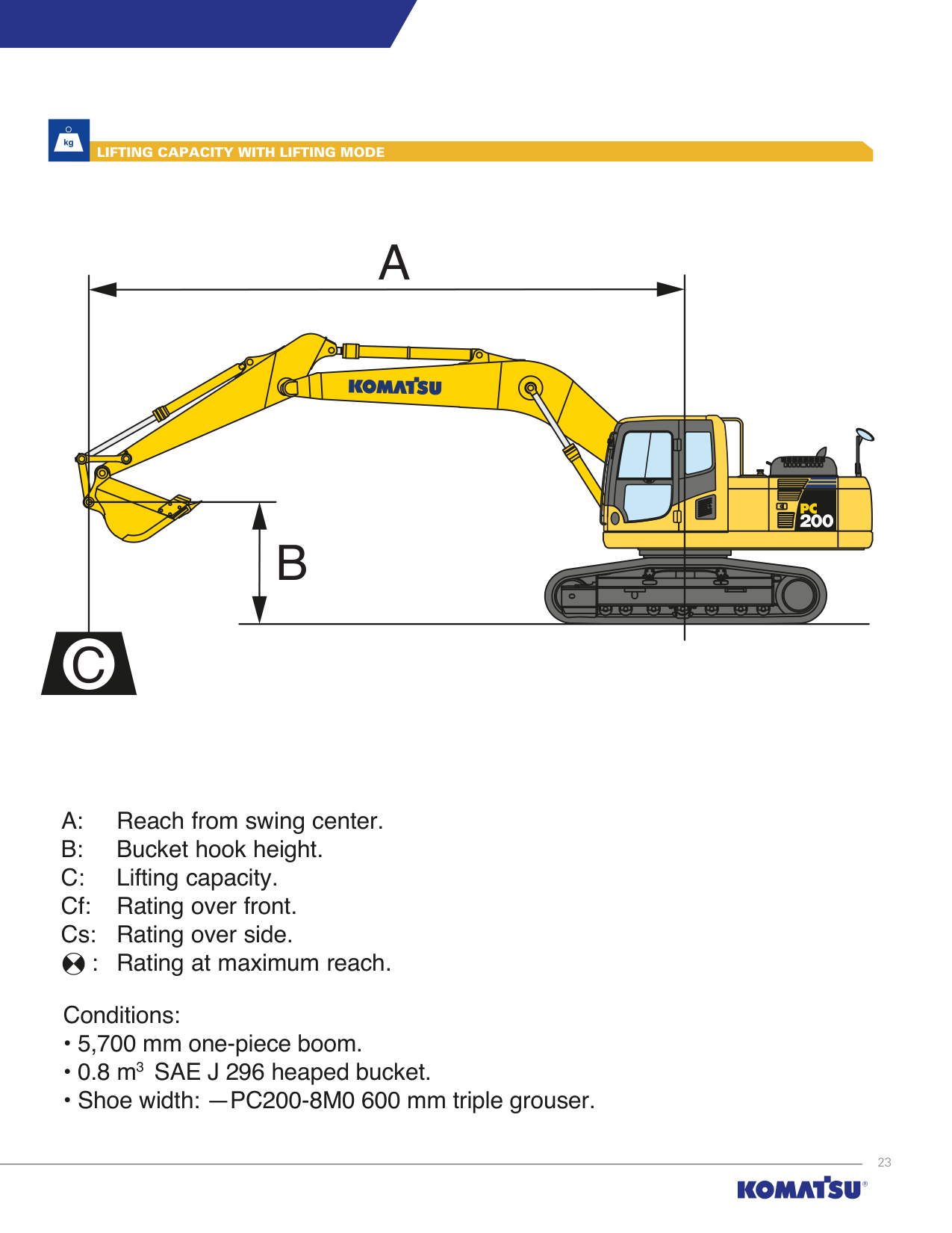
: Rating at maximum reach.
Conditions:
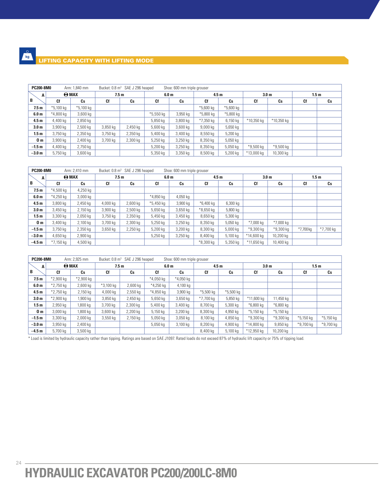
|PC200-8M0 Arm: 1,840 mm Bucket: 0.8 m3 SAE J 296 heaped Shoe: 600 mm triple grouser|PC200-8M0 Arm: 1,840 mm Bucket: 0.8 m3 SAE J 296 heaped Shoe: 600 mm triple grouser|PC200-8M0 Arm: 1,840 mm Bucket: 0.8 m3 SAE J 296 heaped Shoe: 600 mm triple grouser|PC200-8M0 Arm: 1,840 mm Bucket: 0.8 m3 SAE J 296 heaped Shoe: 600 mm triple grouser|PC200-8M0 Arm: 1,840 mm Bucket: 0.8 m3 SAE J 296 heaped Shoe: 600 mm triple grouser|PC200-8M0 Arm: 1,840 mm Bucket: 0.8 m3 SAE J 296 heaped Shoe: 600 mm triple grouser|PC200-8M0 Arm: 1,840 mm Bucket: 0.8 m3 SAE J 296 heaped Shoe: 600 mm triple grouser|PC200-8M0 Arm: 1,840 mm Bucket: 0.8 m3 SAE J 296 heaped Shoe: 600 mm triple grouser|PC200-8M0 Arm: 1,840 mm Bucket: 0.8 m3 SAE J 296 heaped Shoe: 600 mm triple grouser|PC200-8M0 Arm: 1,840 mm Bucket: 0.8 m3 SAE J 296 heaped Shoe: 600 mm triple grouser|PC200-8M0 Arm: 1,840 mm Bucket: 0.8 m3 SAE J 296 heaped Shoe: 600 mm triple grouser|PC200-8M0 Arm: 1,840 mm Bucket: 0.8 m3 SAE J 296 heaped Shoe: 600 mm triple grouser|PC200-8M0 Arm: 1,840 mm Bucket: 0.8 m3 SAE J 296 heaped Shoe: 600 mm triple grouser| |---|---|---|---|---|---|---|---|---|---|---|---|---| |A B|MAX|MAX|7.5 m|7.5 m|6.0 m|6.0 m|4.5 m|4.5 m|3.0 m|3.0 m|1.5 m|1.5 m| |A B|Cf|Cs|Cf|Cs|Cf|Cs|Cf|Cs|Cf|Cs|Cf|Cs| |7.5 m|*5,100 kg|*5,100 kg| | | | |*5,600 kg|*5,600 kg| | | | | |6.0 m|*4,800 kg|3,600 kg| | |*5,550 kg|3,950 kg|*5,800 kg|*5,800 kg| | | | | |4.5 m|4,400 kg|2,850 kg| | |5,850 kg|3,800 kg|*7,350 kg|6,150 kg|*10,350 kg|*10,350 kg| | | |3.0 m|3,900 kg|2,500 kg|3,850 kg|2,450 kg|5,600 kg|3,600 kg|9,000 kg|5,650 kg| | | | | |1.5 m|3,750 kg|2,350 kg|3,750 kg|2,350 kg|5,400 kg|3,400 kg|8,550 kg|5,200 kg| | | | | |O m|3,900 kg|2,400 kg|3,700 kg|2,300 kg|5,250 kg|3,250 kg|8,350 kg|5,050 kg| | | | | |–1.5 m|4,400 kg|2,750 kg| | |5,200 kg|3,250 kg|8,350 kg|5,050 kg|*9,500 kg|*9,500 kg| | | |–3.0 m|5,750 kg|3,600 kg| | |5,350 kg|3,350 kg|8,500 kg|5,200 kg|*13,000 kg|10,300 kg| | |
|PC200-8M0 Arm: 2,410 mm Bucket: 0.8 m3 SAE J 296 heaped Shoe: 600 mm triple grouser|PC200-8M0 Arm: 2,410 mm Bucket: 0.8 m3 SAE J 296 heaped Shoe: 600 mm triple grouser|PC200-8M0 Arm: 2,410 mm Bucket: 0.8 m3 SAE J 296 heaped Shoe: 600 mm triple grouser|PC200-8M0 Arm: 2,410 mm Bucket: 0.8 m3 SAE J 296 heaped Shoe: 600 mm triple grouser|PC200-8M0 Arm: 2,410 mm Bucket: 0.8 m3 SAE J 296 heaped Shoe: 600 mm triple grouser|PC200-8M0 Arm: 2,410 mm Bucket: 0.8 m3 SAE J 296 heaped Shoe: 600 mm triple grouser|PC200-8M0 Arm: 2,410 mm Bucket: 0.8 m3 SAE J 296 heaped Shoe: 600 mm triple grouser|PC200-8M0 Arm: 2,410 mm Bucket: 0.8 m3 SAE J 296 heaped Shoe: 600 mm triple grouser|PC200-8M0 Arm: 2,410 mm Bucket: 0.8 m3 SAE J 296 heaped Shoe: 600 mm triple grouser|PC200-8M0 Arm: 2,410 mm Bucket: 0.8 m3 SAE J 296 heaped Shoe: 600 mm triple grouser|PC200-8M0 Arm: 2,410 mm Bucket: 0.8 m3 SAE J 296 heaped Shoe: 600 mm triple grouser|PC200-8M0 Arm: 2,410 mm Bucket: 0.8 m3 SAE J 296 heaped Shoe: 600 mm triple grouser|PC200-8M0 Arm: 2,410 mm Bucket: 0.8 m3 SAE J 296 heaped Shoe: 600 mm triple grouser| |---|---|---|---|---|---|---|---|---|---|---|---|---| |A B|MAX|MAX|7.5 m|7.5 m|6.0 m|6.0 m|4.5 m|4.5 m|3.0 m|3.0 m|1.5 m|1.5 m| |A B|Cf|Cs|Cf|Cs|Cf|Cs|Cf|Cs|Cf|Cs|Cf|Cs| |7.5 m|*4,500 kg|4,250 kg| | | | | | | | | | | |6.0 m|*4,250 kg|3,000 kg| | |*4,850 kg|4,050 kg| | | | | | | |4.5 m|3,800 kg|2,450 kg|4,000 kg|2,600 kg|*5,450 kg|3,900 kg|*6,400 kg|6,300 kg| | | | |
|3.0 m|3,450 kg|2,150 kg|3,900 kg|2,500 kg|5,650 kg|3,650 kg|*8,650 kg|5,800 kg| | | | | |1.5 m|3,300 kg|2,050 kg|3,750 kg|2,350 kg|5,450 kg|3,450 kg|8,650 kg|5,300 kg| | | | | |O m|3,400 kg|2,100 kg|3,700 kg|2,300 kg|5,250 kg|3,250 kg|8,350 kg|5,050 kg|*7,000 kg|*7,000 kg| | | |–1.5 m|3,750 kg|2,350 kg|3,650 kg|2,250 kg|5,200 kg|3,200 kg|8,300 kg|5,000 kg|*9,300 kg|*9,300 kg|*7,700 kg|*7,700 kg| |–3.0 m|4,650 kg|2,900 kg| | |5,250 kg|3,250 kg|8,400 kg|5,100 kg|*14,600 kg|10,200 kg| | | |–4.5 m|*7,150 kg|4,500 kg| | | | |*8,300 kg|5,350 kg|*11,650 kg|10,400 kg| | |
|PC200-8M0 Arm: 2,925 mm Bucket: 0.8 m3 SAE J 296 heaped Shoe: 600 mm triple grouser|PC200-8M0 Arm: 2,925 mm Bucket: 0.8 m3 SAE J 296 heaped Shoe: 600 mm triple grouser|PC200-8M0 Arm: 2,925 mm Bucket: 0.8 m3 SAE J 296 heaped Shoe: 600 mm triple grouser|PC200-8M0 Arm: 2,925 mm Bucket: 0.8 m3 SAE J 296 heaped Shoe: 600 mm triple grouser|PC200-8M0 Arm: 2,925 mm Bucket: 0.8 m3 SAE J 296 heaped Shoe: 600 mm triple grouser|PC200-8M0 Arm: 2,925 mm Bucket: 0.8 m3 SAE J 296 heaped Shoe: 600 mm triple grouser|PC200-8M0 Arm: 2,925 mm Bucket: 0.8 m3 SAE J 296 heaped Shoe: 600 mm triple grouser|PC200-8M0 Arm: 2,925 mm Bucket: 0.8 m3 SAE J 296 heaped Shoe: 600 mm triple grouser|PC200-8M0 Arm: 2,925 mm Bucket: 0.8 m3 SAE J 296 heaped Shoe: 600 mm triple grouser|PC200-8M0 Arm: 2,925 mm Bucket: 0.8 m3 SAE J 296 heaped Shoe: 600 mm triple grouser|PC200-8M0 Arm: 2,925 mm Bucket: 0.8 m3 SAE J 296 heaped Shoe: 600 mm triple grouser|PC200-8M0 Arm: 2,925 mm Bucket: 0.8 m3 SAE J 296 heaped Shoe: 600 mm triple grouser|PC200-8M0 Arm: 2,925 mm Bucket: 0.8 m3 SAE J 296 heaped Shoe: 600 mm triple grouser| |---|---|---|---|---|---|---|---|---|---|---|---|---| |A B|MAX|MAX|7.5 m|7.5 m|6.0 m|6.0 m|4.5 m|4.5 m|3.0 m|3.0 m|1.5 m|1.5 m| |A B|Cf|Cs|Cf|Cs|Cf|Cs|Cf|Cs|Cf|Cs|Cf|Cs| |7.5 m|*2,900 kg|*2,900 kg| | |*4,050 kg|*4,050 kg| | | | | | | |6.0 m|*2,750 kg|2,600 kg|*3,100 kg|2,600 kg|*4,250 kg|4,100 kg| | | | | | | |4.5 m|*2,750 kg|2,150 kg|4,000 kg|2,550 kg|*4,850 kg|3,900 kg|*5,500 kg|*5,500 kg| | | | | |3.0 m|*2,900 kg|1,900 kg|3,850 kg|2,450 kg|5,650 kg|3,650 kg|*7,700 kg|5,850 kg|*11,600 kg|11,450 kg| | | |1.5 m|2,950 kg|1,800 kg|3,700 kg|2,300 kg|5,400 kg|3,400 kg|8,700 kg|5,300 kg|*6,800 kg|*6,800 kg| | | |O m|3,000 kg|1,800 kg|3,600 kg|2,200 kg|5,150 kg|3,200 kg|8,300 kg|4,950 kg|*5,150 kg|*5,150 kg| | | |–1.5 m|3,300 kg|2,000 kg|3,550 kg|2,150 kg|5,050 kg|3,050 kg|8,100 kg|4,850 kg|*9,300 kg|*9,300 kg|*5,150 kg|*5,150 kg| |–3.0 m|3,950 kg|2,400 kg| | |5,050 kg|3,100 kg|8,200 kg|4,900 kg|*14,800 kg|9,850 kg|*9,700 kg|*9,700 kg| |–4.5 m|5,700 kg|3,500 kg| | | | |8,400 kg|5,100 kg|*12,950 kg|10,200 kg| | |
24
B C
A: Reach from swing center. B: Bucket hook height. C: Lifting capacity. Cf: Rating over front. Cs: Rating over side.
: Rating at maximum reach.
Conditions:
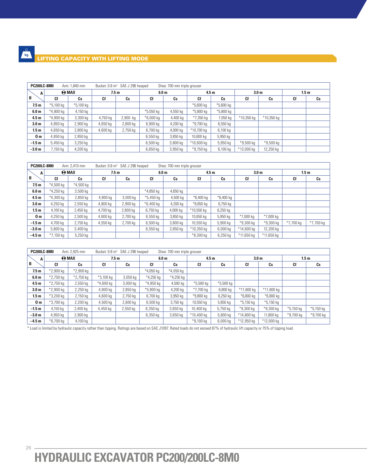
|PC200LC-8M0 Arm: 1,840 mm Bucket: 0.8 m3 SAE J 296 heaped Shoe: 700 mm triple grouser|PC200LC-8M0 Arm: 1,840 mm Bucket: 0.8 m3 SAE J 296 heaped Shoe: 700 mm triple grouser|PC200LC-8M0 Arm: 1,840 mm Bucket: 0.8 m3 SAE J 296 heaped Shoe: 700 mm triple grouser|PC200LC-8M0 Arm: 1,840 mm Bucket: 0.8 m3 SAE J 296 heaped Shoe: 700 mm triple grouser|PC200LC-8M0 Arm: 1,840 mm Bucket: 0.8 m3 SAE J 296 heaped Shoe: 700 mm triple grouser|PC200LC-8M0 Arm: 1,840 mm Bucket: 0.8 m3 SAE J 296 heaped Shoe: 700 mm triple grouser|PC200LC-8M0 Arm: 1,840 mm Bucket: 0.8 m3 SAE J 296 heaped Shoe: 700 mm triple grouser|PC200LC-8M0 Arm: 1,840 mm Bucket: 0.8 m3 SAE J 296 heaped Shoe: 700 mm triple grouser|PC200LC-8M0 Arm: 1,840 mm Bucket: 0.8 m3 SAE J 296 heaped Shoe: 700 mm triple grouser|PC200LC-8M0 Arm: 1,840 mm Bucket: 0.8 m3 SAE J 296 heaped Shoe: 700 mm triple grouser|PC200LC-8M0 Arm: 1,840 mm Bucket: 0.8 m3 SAE J 296 heaped Shoe: 700 mm triple grouser|PC200LC-8M0 Arm: 1,840 mm Bucket: 0.8 m3 SAE J 296 heaped Shoe: 700 mm triple grouser|PC200LC-8M0 Arm: 1,840 mm Bucket: 0.8 m3 SAE J 296 heaped Shoe: 700 mm triple grouser| |---|---|---|---|---|---|---|---|---|---|---|---|---| |A B|MAX|MAX|7.5 m|7.5 m|6.0 m|6.0 m|4.5 m|4.5 m|3.0 m|3.0 m|1.5 m|1.5 m| |A B|Cf|Cs|Cf|Cs|Cf|Cs|Cf|Cs|Cf|Cs|Cf|Cs| |7.5 m|*5,100 kg|*5,100 kg| | | | |*5,600 kg|*5,600 kg| | | | | |6.0 m|*4,800 kg|4,150 kg| | |*5,550 kg|4,550 kg|*5,800 kg|*5,800 kg| | | | | |4.5 m|*4,900 kg|3,300 kg|4,750 kg|2,900 kg|*6,000 kg|4,400 kg|*7,350 kg|7,050 kg|*10,350 kg|*10,350 kg| | | |3.0 m|4,850 kg|2,900 kg|4,650 kg|2,800 kg|6,900 kg|4,200 kg|*9,700 kg|6,550 kg| | | | | |1.5 m|4,650 kg|2,800 kg|4,600 kg|2,750 kg|6,700 kg|4,000 kg|*10,700 kg|6,100 kg| | | | | |O m|4,850 kg|2,850 kg| | |6,550 kg|3,850 kg|10,600 kg|5,950 kg| | | | | |–1.5 m|5,450 kg|3,250 kg| | |6,500 kg|3,800 kg|*10,600 kg|5,950 kg|*9,500 kg|*9,500 kg| | | |–3.0 m|7,150 kg|4,200 kg| | |6,650 kg|3,950 kg|*9,750 kg|6,100 kg|*13,000 kg|12,250 kg| | |
|PC200LC-8M0 Arm: 2,410 mm Bucket: 0.8 m3 SAE J 296 heaped Shoe: 700 mm triple grouser|PC200LC-8M0 Arm: 2,410 mm Bucket: 0.8 m3 SAE J 296 heaped Shoe: 700 mm triple grouser|PC200LC-8M0 Arm: 2,410 mm Bucket: 0.8 m3 SAE J 296 heaped Shoe: 700 mm triple grouser|PC200LC-8M0 Arm: 2,410 mm Bucket: 0.8 m3 SAE J 296 heaped Shoe: 700 mm triple grouser|PC200LC-8M0 Arm: 2,410 mm Bucket: 0.8 m3 SAE J 296 heaped Shoe: 700 mm triple grouser|PC200LC-8M0 Arm: 2,410 mm Bucket: 0.8 m3 SAE J 296 heaped Shoe: 700 mm triple grouser|PC200LC-8M0 Arm: 2,410 mm Bucket: 0.8 m3 SAE J 296 heaped Shoe: 700 mm triple grouser|PC200LC-8M0 Arm: 2,410 mm Bucket: 0.8 m3 SAE J 296 heaped Shoe: 700 mm triple grouser|PC200LC-8M0 Arm: 2,410 mm Bucket: 0.8 m3 SAE J 296 heaped Shoe: 700 mm triple grouser|PC200LC-8M0 Arm: 2,410 mm Bucket: 0.8 m3 SAE J 296 heaped Shoe: 700 mm triple grouser|PC200LC-8M0 Arm: 2,410 mm Bucket: 0.8 m3 SAE J 296 heaped Shoe: 700 mm triple grouser|PC200LC-8M0 Arm: 2,410 mm Bucket: 0.8 m3 SAE J 296 heaped Shoe: 700 mm triple grouser|PC200LC-8M0 Arm: 2,410 mm Bucket: 0.8 m3 SAE J 296 heaped Shoe: 700 mm triple grouser| |---|---|---|---|---|---|---|---|---|---|---|---|---| |A B|MAX|MAX|7.5 m|7.5 m|6.0 m|6.0 m|4.5 m|4.5 m|3.0 m|3.0 m|1.5 m|1.5 m| |A B|Cf|Cs|Cf|Cs|Cf|Cs|Cf|Cs|Cf|Cs|Cf|Cs| |7.5 m|*4,500 kg|*4,500 kg| | | | | | | | | | | |6.0 m|*4,250 kg|3,500 kg| | |*4,850 kg|4,650 kg| | | | | | | |4.5 m|*4,300 kg|2,850 kg|4,900 kg|3,000 kg|*5,450 kg|4,500 kg|*6,400 kg|*6,400 kg| | | | | |3.0 m|4,250 kg|2,550 kg|4,800 kg|2,900 kg|*6,400 kg|4,200 kg|*8,650 kg|6,750 kg| | | | | |1.5 m|4,100 kg|2,450 kg|4,700 kg|2,800 kg|6,750 kg|4,000 kg|*10,550 kg|6,250 kg| | | | | |O m|4,250 kg|2,500 kg|4,600 kg|2,700 kg|6,550 kg|3,850 kg|10,650 kg|5,950 kg|*7,000 kg|*7,000 kg| | | |–1.5 m|4,700 kg|2,750 kg|4,550 kg|2,700 kg|6,500 kg|3,800 kg|10,550 kg|5,900 kg|*9,300 kg|*9,300 kg|*7,700 kg|*7,700 kg| |–3.0 m|5,800 kg|3,400 kg| | |6,550 kg|3,850 kg|*10,350 kg|6,000 kg|*14,600 kg|12,200 kg| | | |–4.5 m|*7,150 kg|5,250 kg| | | | |*8,300 kg|6,250 kg|*11,650 kg|*11,650 kg| | |
|PC200LC-8M0 Arm: 2,925 mm Bucket: 0.8 m3 SAE J 296 heaped Shoe: 700 mm triple grouser|PC200LC-8M0 Arm: 2,925 mm Bucket: 0.8 m3 SAE J 296 heaped Shoe: 700 mm triple grouser|PC200LC-8M0 Arm: 2,925 mm Bucket: 0.8 m3 SAE J 296 heaped Shoe: 700 mm triple grouser|PC200LC-8M0 Arm: 2,925 mm Bucket: 0.8 m3 SAE J 296 heaped Shoe: 700 mm triple grouser|PC200LC-8M0 Arm: 2,925 mm Bucket: 0.8 m3 SAE J 296 heaped Shoe: 700 mm triple grouser|PC200LC-8M0 Arm: 2,925 mm Bucket: 0.8 m3 SAE J 296 heaped Shoe: 700 mm triple grouser|PC200LC-8M0 Arm: 2,925 mm Bucket: 0.8 m3 SAE J 296 heaped Shoe: 700 mm triple grouser|PC200LC-8M0 Arm: 2,925 mm Bucket: 0.8 m3 SAE J 296 heaped Shoe: 700 mm triple grouser|PC200LC-8M0 Arm: 2,925 mm Bucket: 0.8 m3 SAE J 296 heaped Shoe: 700 mm triple grouser|PC200LC-8M0 Arm: 2,925 mm Bucket: 0.8 m3 SAE J 296 heaped Shoe: 700 mm triple grouser|PC200LC-8M0 Arm: 2,925 mm Bucket: 0.8 m3 SAE J 296 heaped Shoe: 700 mm triple grouser|PC200LC-8M0 Arm: 2,925 mm Bucket: 0.8 m3 SAE J 296 heaped Shoe: 700 mm triple grouser|PC200LC-8M0 Arm: 2,925 mm Bucket: 0.8 m3 SAE J 296 heaped Shoe: 700 mm triple grouser| |---|---|---|---|---|---|---|---|---|---|---|---|---| |A B|MAX|MAX|7.5 m|7.5 m|6.0 m|6.0 m|4.5 m|4.5 m|3.0 m|3.0 m|1.5 m|1.5 m| |A B|Cf|Cs|Cf|Cs|Cf|Cs|Cf|Cs|Cf|Cs|Cf|Cs| |7.5 m|*2,900 kg|*2,900 kg| | |*4,050 kg|*4,050 kg| | | | | | | |6.0 m|*2,750 kg|*2,750 kg|*3,100 kg|3,050 kg|*4,250 kg|*4,250 kg| | | | | | | |4.5 m|*2,750 kg|2,550 kg|*4,600 kg|3,000 kg|*4,850 kg|4,500 kg|*5,500 kg|*5,500 kg| | | | | |3.0 m|*2,900 kg|2,250 kg|4,800 kg|2,850 kg|*5,900 kg|4,200 kg|*7,700 kg|6,800 kg|*11,600 kg|*11,600 kg| | | |1.5 m|*3,200 kg|2,150 kg|4,600 kg|2,750 kg|6,700 kg|3,950 kg|*9,800 kg|6,250 kg|*6,800 kg|*6,800 kg| | | |O m|*3,700 kg|2,200 kg|4,500 kg|2,600 kg|6,500 kg|3,750 kg|10,550 kg|5,850 kg|*5,150 kg|*5,150 kg| | | |–1.5 m|4,150 kg|2,400 kg|4,450 kg|2,550 kg|6,350 kg|3,650 kg|10,400 kg|5,750 kg|*9,300 kg|*9,300 kg|*5,150 kg|*5,150 kg| |–3.0 m|4,950 kg|2,900 kg| | |6,350 kg|3,650 kg|*10,400 kg|5,800 kg|*14,800 kg|11,800 kg|*9,700 kg|*9,700 kg| |–4.5 m|*6,700 kg|4,100 kg| | | | |*9,100 kg|6,000 kg|*12,950 kg|*12,000 kg| | |
26
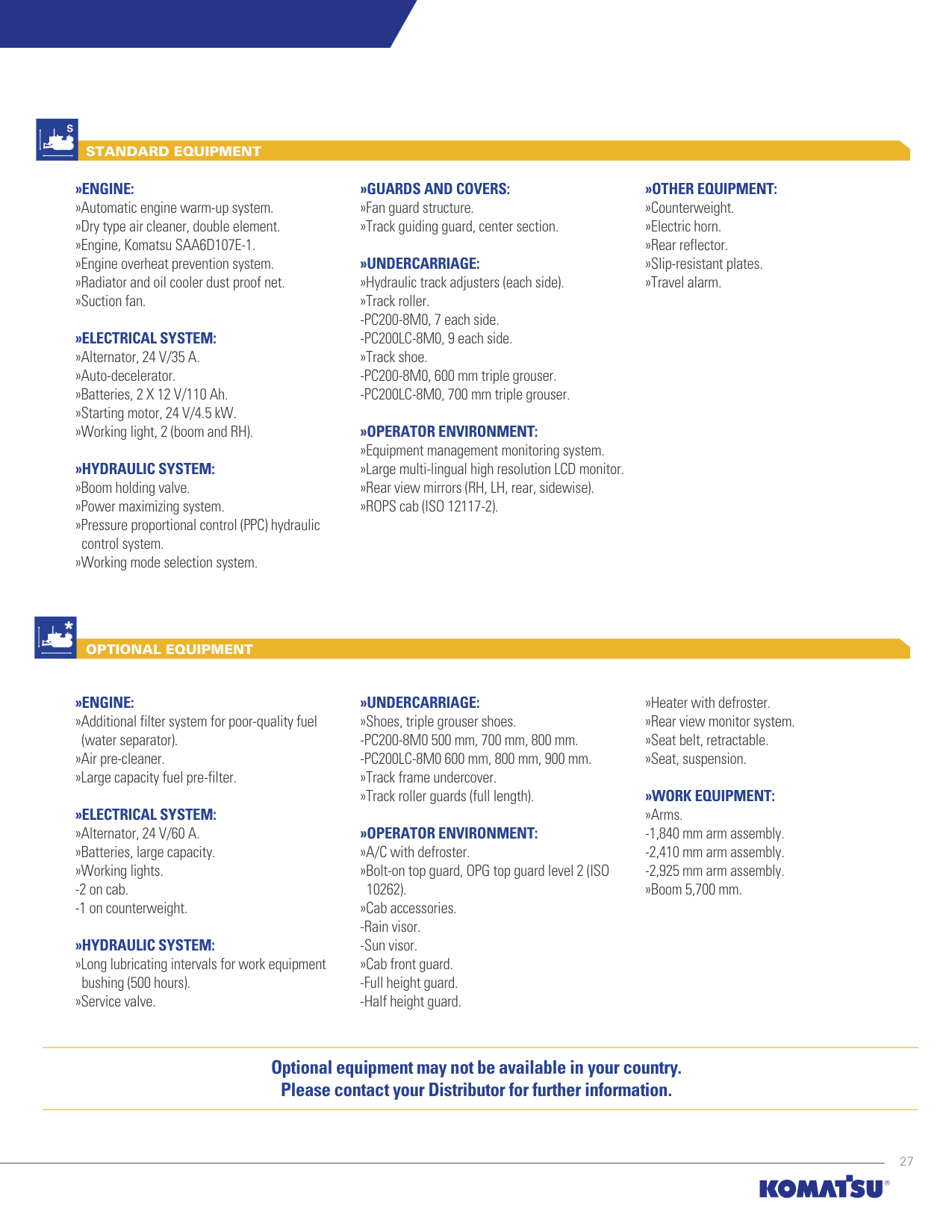
STANDARD EQUIPMENT
»ENGINE: »Automatic engine warm-up system. »Dry type air cleaner, double element. »Engine, Komatsu SAA6D107E-1. »Engine overheat prevention system. »Radiator and oil cooler dust proof net. »Suction fan.
»ELECTRICAL SYSTEM: »Alternator, 24 V/35 A. »Auto-decelerator. »Batteries, 2 X 12 V/110 Ah. »Starting motor, 24 V/4.5 kW. »Working light, 2 (boom and RH).
»HYDRAULIC SYSTEM: »Boom holding valve. »Power maximizing system. »Pressure proportional control (PPC) hydraulic
control system. »Working mode selection system.
»GUARDS AND COVERS: »Fan guard structure. »Track guiding guard, center section.
»UNDERCARRIAGE: »Hydraulic track adjusters (each side). »Track roller.
»OPERATOR ENVIRONMENT: »Equipment management monitoring system. »Large multi-lingual high resolution LCD monitor. »Rear view mirrors (RH, LH, rear, sidewise). »ROPS cab (ISO 12117-2).
»OTHER EQUIPMENT: »Counterweight. »Electric horn. »Rear reflector. »Slip-resistant plates. »Travel alarm.
OPTIONAL EQUIPMENT
»ENGINE: »Additional filter system for poor-quality fuel
(water separator). »Air pre-cleaner. »Large capacity fuel pre-filter.
»ELECTRICAL SYSTEM: »Alternator, 24 V/60 A. »Batteries, large capacity. »Working lights.
»HYDRAULIC SYSTEM: »Long lubricating intervals for work equipment
bushing (500 hours). »Service valve.
»UNDERCARRIAGE: »Shoes, triple grouser shoes.
»OPERATOR ENVIRONMENT: »A/C with defroster. »Bolt-on top guard, OPG top guard level 2 (ISO
10262). »Cab accessories.
»Heater with defroster. »Rear view monitor system. »Seat belt, retractable. »Seat, suspension.
################ »WORK EQUIPMENT: »Arms.
############ Optional equipment may not be available in your country. Please contact your Distributor for further information.
27
Product designs, specifications and/or data in this document are provided for informational purposes only and are not warranties of any kind. Product designs and/or specifications may be changed at any time without notice. The only warranties that apply to sales of products and services are standard written warranties, which will be furnished upon request.
Komatsu, and related logo are trademarks of Komatsu Ltd. or one of its affiliates. © 2017 Komatsu Ltd. or one of its affiliates. All rights reserved.
|For further information, contact your distributor or visit our website www.komatsulatinoamerica.com| |---|
################# KLAT-EQ028/001-2018