
Ask AI
— answers from the official manualAnswers from the official manual.
Common questions
Common Questions
8 totalHow do I check if my Mercury outboard motor has the correct propeller?
Ensure the propeller diameter and pitch match those recommended by your dealer or manufacturer for optimal performance in your boating application. Check full throttle RPM under normal load conditions to ensure it falls within the specified range. (Page 8)
What safety precautions should I take when operating my Mercury outboard at high speeds?
Do not overload your boat or exceed its horsepower capacity as marked on the U.S Coast Guard Capacity plate. Always use a lanyard stop switch connected to your PFD for emergency stops if you fall overboard. (Page 8)
How do I perform engine break-in procedures?
Follow the recommended daily inspection checklist and idle the engine at a steady rate for 10-20 minutes until warm, then accelerate gently to a higher throttle position (but not full speed) maintaining each RPM level incrementally for an additional ten minutes. Refer to the manual for specific model guidance on break-in procedure details and durations. (Page 67)
What is the purpose of a lanyard stop switch?
The lanyard stop switch immediately turns off the engine if you separate from your position while attached to it via a safety line, reducing injury risk in case of accidental ejection or movement away from the operator's station. (Page 10)
How often should I check my oil level on the Mercury outboard?
Inspect and top up engine oil before every use, particularly after significant usage periods or whenever signs of contaminated oil are noticed. Always tilt the outboard past vertical to drain trapped oil back into the sump before checking. (Page 38)
What steps should I take if my engine fails to start?
Follow these troubleshooting steps: Ensure fuel supply and quality, check spark plugs, inspect battery connections for corrosion, verify safety switches are activated correctly. If issues persist, consult your dealer or service manual for further diagnostics. (Page 130)
Full Manual
146 pages

8M0175492 920eng
© 2020 Mercury MarineV8 (200–300), V6 (175–225) CMS DTS
Operation and Maintenance Manual
Welcome You have selected one of the finest marine power packages available. It incorporates numerous design features to ensure operating ease and durability. With proper care and maintenance, you will enjoy using this product for many boating seasons. To ensure maximum performance and carefree use, we ask that you thoroughly read this manual. The Operation and Maintenance Manual contains specific instructions for using and maintaining your product. Keep this manual with the product for ready reference whenever you are on the water. Thank you for purchasing one of our products. We sincerely hope your boating will be pleasant. Mercury Marine, Fond du Lac, Wisconsin, U.S.A.
Name / function: Christopher D. Drees, President, Mercury Marine

######################## Read This Manual Thoroughly
############################# IMPORTANT: If you do not understand any portion of this manual, contact your dealer. Your dealer can also provide a demonstration of actual starting and operating procedures.
Notice Throughout this publication and on your power package, safety alerts labeled
WARNING and CAUTION (accompanied by the symbol ! ), are used to alert you to special instructions concerning a particular service or operation that may be hazardous if performed incorrectly or carelessly. Observe these alerts carefully. These safety alerts alone cannot eliminate the hazards that they signal. Strict compliance to these special instructions when performing the service, plus common sense operation, are major accident prevention measures.
||!| |---|
WARNING| |---|

|Indicates a hazardous situation which, if not avoided, could result in death or serious injury.|
|| | |---| |!| | |
CAUTION| |---| |Indicates a hazardous situation which, if not avoided, could result in minor or moderate injury.|
eng i
Additional alerts provide information that requires special attention:
|NOTICE| |---| |Indicates a situation which, if not avoided, could result in engine or major component failure.|
IMPORTANT: Identifies information essential to the successful completion of the task. NOTE:Indicates information that helps in the understanding of a particular step or action.
IMPORTANT: The operator (driver) is responsible for the correct and safe operation of the boat, the equipment aboard, and the safety of all occupants aboard. We strongly recommend that the operator read this Operation and Maintenance Manual and thoroughly understand the operational instructions for the power package and all related accessories before the boat is used.
|California Proposition 65
WARNING: This product can expose you to chemicals including gasoline engine exhaust, which is known to the State of California to cause cancer and birth defects or other reproductive harm. For more information go to www.P65Warnings.ca.gov.
|
|---|
Descriptions and specifications contained herein were in effect at the time this was approved for printing. Mercury Marine, whose policies are based on continuous improvement, reserves the right to discontinue models at any time or to change specifications or designs without notice and without incurring obligation.
Warranty Message The product you have purchased comes with a Mercury Marine Limited Warranty. The terms of the warranty are set forth in the Warranty Manual, which can be accessed any time on the Mercury Marine website, at http://
www.mercurymarine.com/warranty‑manual. The Warranty Manual contains a description of what is covered, what is not covered, the duration of coverage, how to best obtain warranty coverage, important disclaimers, limitations,
and waivers, and other related information. Please review this important information.
ii eng
Mercury Marine products are designed and manufactured to comply with our own high quality standards, applicable industry standards and regulations, and certain emissions regulations. At Mercury Marine every engine is operated and tested before it is boxed for shipment to make sure that the product is ready for use. In addition, certain Mercury Marine products are tested in a controlled and monitored environment, for up to 10 hours of engine run time, in order to verify and make a record of compliance with applicable standards and regulations. All Mercury Marine product, sold as new, receives the applicable limited warranty coverage, whether the engine participated in one of the test programs described above or not.
Copyright and Trademark Information
© MERCURY MARINE. All rights reserved. Reproduction in whole or in part without permission is prohibited.
Alpha, Axius, Bravo One, Bravo Two, Bravo Three, Circle M with Waves Logo, GO BOLDLY, K‑planes, Mariner, MerCathode, MerCruiser, Mercury, Mercury with Waves Logo, Mercury Marine, Mercury Precision Parts, Mercury Propellers, Mercury Racing, MotorGuide, OptiMax, Pro XS, Quicksilver, SeaCore, Skyhook, SmartCraft, Sport‑Jet, Verado, VesselView, Zero Effort, Zeus, #1 On the Water and We're Driven to Win are registered trademarks of Brunswick Corporation. Mercury Product Protection is a registered service mark of Brunswick Corporation. All other marks are the property of their respective owners.
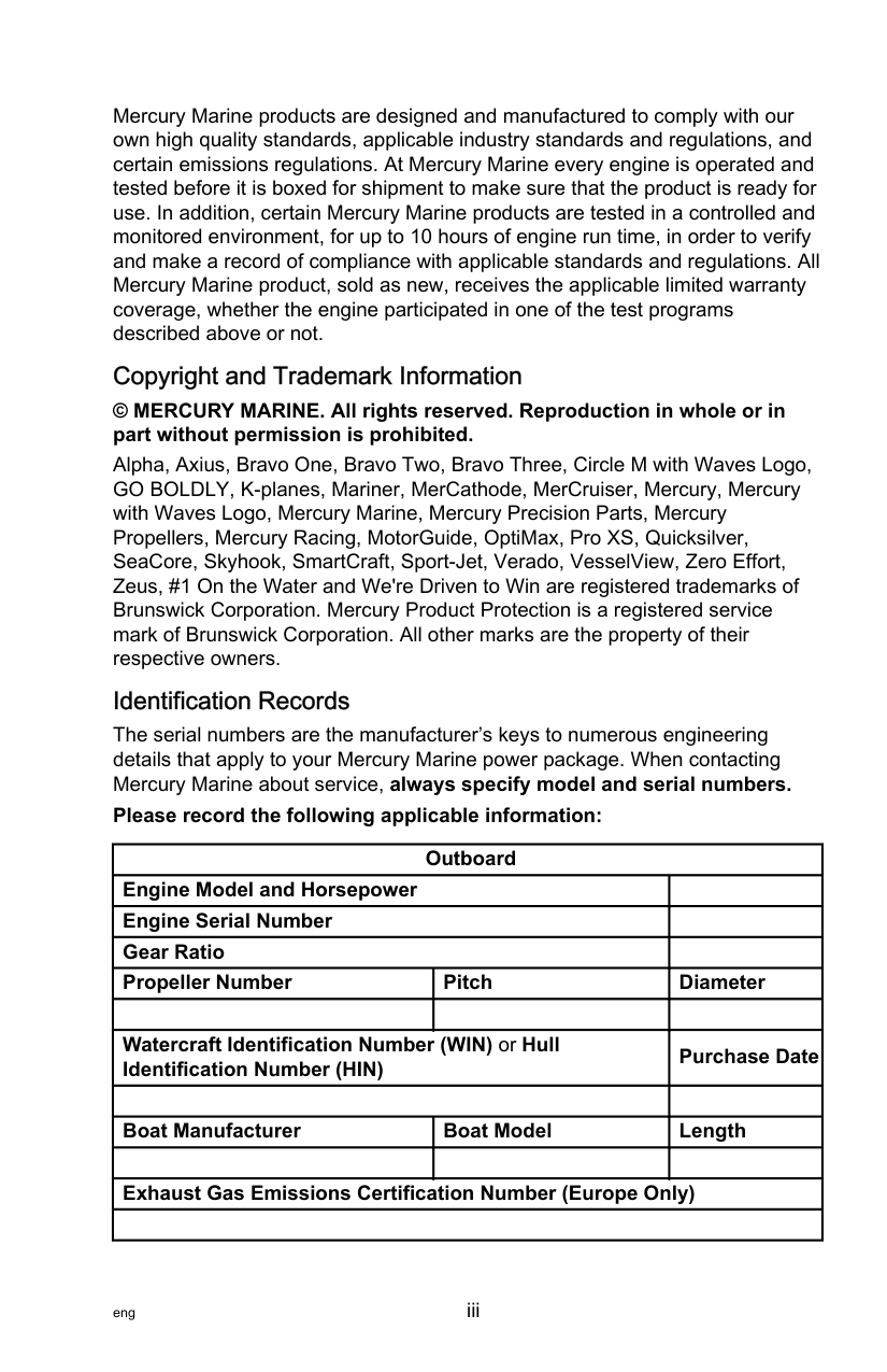
Identification Records The serial numbers are the manufacturer’s keys to numerous engineering details that apply to your Mercury Marine power package. When contacting Mercury Marine about service, always specify model and serial numbers. Please record the following applicable information:
|Outboard|Outboard|Outboard| |---|---|---| |Engine Model and Horsepower|Engine Model and Horsepower| |
|Engine Serial Number|Engine Serial Number| | |Gear Ratio|Gear Ratio| | |Propeller Number|Pitch|Diameter| | | | | |Watercraft Identification Number (WIN) or Hull Identification Number (HIN)|Watercraft Identification Number (WIN) or Hull Identification Number (HIN)|Purchase Date| | | | | |Boat Manufacturer|Boat Model|Length| | | | | |Exhaust Gas Emissions Certification Number (Europe Only)|Exhaust Gas Emissions Certification Number (Europe Only)|Exhaust Gas Emissions Certification Number (Europe Only)| | | | |
############################## eng iv
############################# General Information
Boater's Responsibilities.....................................................................................1 Before Operating Your Outboard........................................................................ 1 Boat Horsepower Capacity................................................................................. 1 High‑Speed and High‑Performance Boat Operation.......................................... 2 Propeller Selection..............................................................................................2 Outboard Remote Control Models ..................................................................... 4 Lanyard Stop Switch........................................................................................... 4 Protecting People in the Water........................................................................... 7 Passenger Safety Message ‑ Pontoon Boats and Deck Boats...........................7 Wave and Wake Jumping................................................................................... 9 Impact with Underwater Hazards........................................................................9 Exhaust Emissions........................................................................................... 11 Selecting Accessories for Your Outboard......................................................... 13 Safe Boating Recommendations...................................................................... 13 Recording Serial Number................................................................................. 16 Specification—V6 Models................................................................................. 17 Specification—V8 Models................................................................................. 21 Component Identification.................................................................................. 28 Gearcase Identification..................................................................................... 29
############################# Transporting
Aquatic Invasive Species (AIS).........................................................................31 Trailering Boat/Outboard.................................................................................. 31
############################# Fuel and Oil
Fuel Requirements........................................................................................... 33 Fuel Additives................................................................................................... 34 Low Permeation Fuel Hose Requirement ........................................................ 34 Fuel Demand Valve.......................................................................................... 34 Engine Oil Recommendations—Standard, Pro XS, and Race (R) Models.......35 Engine Oil Recommendations—SeaPro Models.............................................. 35 Checking and Adding Engine Oil...................................................................... 36
############################# Features and Controls
Adaptive Speed Control.................................................................................... 40 Panel Mount Control Features and Operation.................................................. 40 Slim Binnacle Control Features and Operation................................................ 42 Dual‑Handle Console Control Features and Operation.................................... 48 Shadow Mode Control with CAN Trackpad Features and Operation............... 56 Hot Foot............................................................................................................ 57 Zero Effort Controls.......................................................................................... 60 Warning System............................................................................................... 60 Power Trim and Tilt...........................................................................................62
############################# Operation
Important Daily Inspection Before Each Use ................................................... 67 Prestarting Check List.......................................................................................67 Operating in Freezing Temperatures................................................................ 67 Operating in Saltwater or Polluted Water......................................................... 68 Operating at High Elevations............................................................................ 69 Effects of Elevation and Weather on Performance........................................... 69 Setting Trim Angle while Running Engine at Idle Speed.................................. 70 Engine Break‑in Procedure...............................................................................70 Fuel Supply Module Priming Procedure........................................................... 71 Starting the Engine........................................................................................... 72 Gear Shifting..................................................................................................... 75 Stopping the Engine......................................................................................... 78 Proper Outboard Tilt Positioning During Periods of Non‑Use ..........................78
############################# Maintenance
Cleaning Care Recommendations.................................................................... 80 EPA Emissions Regulations............................................................................. 83 Inspection and Maintenance Schedule............................................................. 84 Maintenance Schedule Decals......................................................................... 86 Flushing the Cooling System............................................................................ 90 Top Cowl Removal and Installation.................................................................. 91 Battery Inspection ............................................................................................ 93 Battery Cables and Clean Power Harness....................................................... 94 Fuel System...................................................................................................... 96 Corrosion Control Anode.................................................................................. 98 Propeller Replacement..................................................................................... 99 Propeller Replacement—31.75 mm (1‑1/4 in.) Diameter Propeller Shaft....... 104 Spark Plug Inspection and Replacement........................................................106 Fuses.............................................................................................................. 108 Alternator Drive Belt .......................................................................................110 Lubrication Points........................................................................................... 110 Checking Power Trim Fluid.............................................................................112 Checking Hydraulic Steering Fluid..................................................................113 Checking Power Steering Fluid...................................................................... 114 Changing Engine Oil and Filter....................................................................... 114 Checking Engine Oil Level..............................................................................119 Exhaust Water Strainer Inspection................................................................. 120 Gearcase Lubricant........................................................................................ 122
############################# Storage
Storage Preparation........................................................................................128 Protecting External Outboard Components.................................................... 128 Protecting Internal Engine Components......................................................... 128 Gearcase........................................................................................................ 129 Positioning Outboard for Storage................................................................... 129 Battery Storage............................................................................................... 129
############################# Troubleshooting
Starter Motor Will Not Crank the Engine.........................................................130 Engine Will Not Start.......................................................................................130 Engine Starts But Will Not Shift Into Gear...................................................... 130 Engine Runs Erratically.................................................................................. 130 Performance Loss...........................................................................................131 Battery Will Not Hold Charge.......................................................................... 131

eng vii
############################# Owner Service Assistance
Service Assistance......................................................................................... 132 Ordering Literature..........................................................................................134
############################# Maintenance Log
Maintenance Log............................................................................................ 136
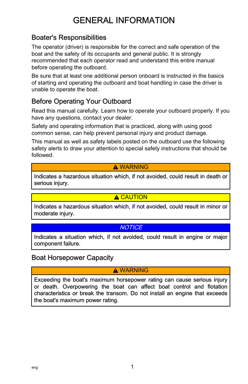
Boater's Responsibilities The operator (driver) is responsible for the correct and safe operation of the boat and the safety of its occupants and general public. It is strongly recommended that each operator read and understand this entire manual before operating the outboard. Be sure that at least one additional person onboard is instructed in the basics of starting and operating the outboard and boat handling in case the driver is unable to operate the boat.
Before Operating Your Outboard Read this manual carefully. Learn how to operate your outboard properly. If you have any questions, contact your dealer. Safety and operating information that is practiced, along with using good common sense, can help prevent personal injury and product damage. This manual as well as safety labels posted on the outboard use the following safety alerts to draw your attention to special safety instructions that should be followed.
||!| |---|
WARNING| |---| |Indicates a hazardous situation which, if not avoided, could result in death or serious injury.|
|| | |---| |!| | |
CAUTION|
|---| |Indicates a hazardous situation which, if not avoided, could result in minor or moderate injury.|
|NOTICE| |---| |Indicates a situation which, if not avoided, could result in engine or major component failure.|
######################## Boat Horsepower Capacity
||!| |---|
WARNING| |---| |Exceeding the boat's maximum horsepower rating can cause serious injury or death. Overpowering the boat can affect boat control and flotation characteristics or break the transom. Do not install an engine that exceeds the boat's maximum power rating.|
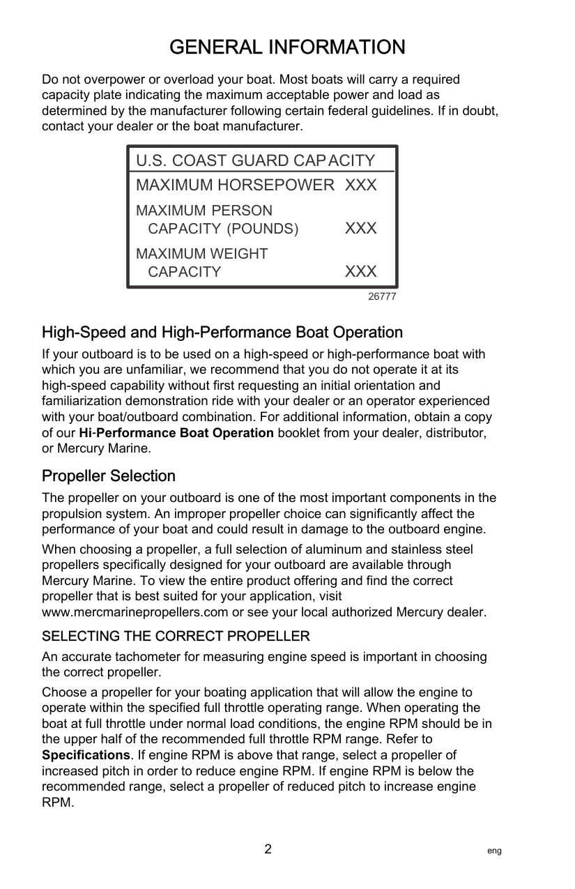
Do not overpower or overload your boat. Most boats will carry a required capacity plate indicating the maximum acceptable power and load as determined by the manufacturer following certain federal guidelines. If in doubt, contact your dealer or the boat manufacturer.
|U.S. COAST GUARD CAPACITY| |---| |MAXIMUM HORSEPOWER XXX MAXIMUM PERSON
CAPACITY (POUNDS) XXX MAXIMUM WEIGHT
CAPACITY XXX|
26777
High‑Speed and High‑Performance Boat Operation If your outboard is to be used on a high‑speed or high‑performance boat with which you are unfamiliar, we recommend that you do not operate it at its high‑speed capability without first requesting an initial orientation and familiarization demonstration ride with your dealer or an operator experienced with your boat/outboard combination. For additional information, obtain a copy of our Hi‑Performance Boat Operation booklet from your dealer, distributor, or Mercury Marine.
Propeller Selection The propeller on your outboard is one of the most important components in the propulsion system. An improper propeller choice can significantly affect the performance of your boat and could result in damage to the outboard engine. When choosing a propeller, a full selection of aluminum and stainless steel propellers specifically designed for your outboard are available through Mercury Marine. To view the entire product offering and find the correct propeller that is best suited for your application, visit www.mercmarinepropellers.com or see your local authorized Mercury dealer. SELECTING THE CORRECT PROPELLER An accurate tachometer for measuring engine speed is important in choosing the correct propeller. Choose a propeller for your boating application that will allow the engine to operate within the specified full throttle operating range. When operating the boat at full throttle under normal load conditions, the engine RPM should be in the upper half of the recommended full throttle RPM range. Refer to Specifications. If engine RPM is above that range, select a propeller of
increased pitch in order to reduce engine RPM. If engine RPM is below the recommended range, select a propeller of reduced pitch to increase engine RPM.
############################# IMPORTANT: To ensure proper fit, and performance, Mercury Marine recommends the use of Mercury or Quicksilver branded propellers and mounting hardware.
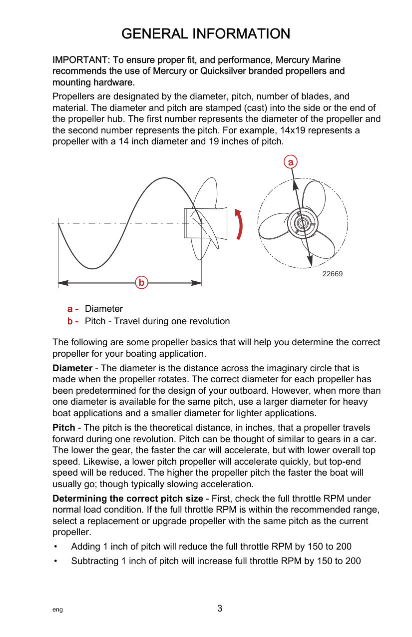
Propellers are designated by the diameter, pitch, number of blades, and material. The diameter and pitch are stamped (cast) into the side or the end of the propeller hub. The first number represents the diameter of the propeller and the second number represents the pitch. For example, 14x19 represents a propeller with a 14 inch diameter and 19 inches of pitch.
######################### a
b
22669
The following are some propeller basics that will help you determine the correct propeller for your boating application. Diameter ‑ The diameter is the distance across the imaginary circle that is made when the propeller rotates. The correct diameter for each propeller has been predetermined for the design of your outboard. However, when more than one diameter is available for the same pitch, use a larger diameter for heavy boat applications and a smaller diameter for lighter applications. Pitch ‑ The pitch is the theoretical distance, in inches, that a propeller travels forward during one revolution. Pitch can be thought of similar to gears in a car. The lower the gear, the faster the car will accelerate, but with lower overall top speed. Likewise, a lower pitch propeller will accelerate quickly, but top‑end speed will be reduced. The higher the propeller pitch the faster the boat will usually go; though typically slowing acceleration. Determining the correct pitch size ‑ First, check the full throttle RPM under normal load condition. If the full throttle RPM is within the recommended range, select a replacement or upgrade propeller with the same pitch as the current propeller.
• Upgrading from a 3‑blade propeller to a 4‑blade propeller will generally
decrease full throttle RPM by 50 to 100 IMPORTANT: Avoid damage to the engine. Never use a propeller that allows the engine to exceed the recommended full throttle RPM range when under normal full throttle operation.
PROPELLER MATERIAL Most propellers manufactured by Mercury Marine are made from either aluminum or stainless steel. Aluminum is suitable for general purpose use and is standard equipment on many new boats. Stainless steel is over five times more durable than aluminum and typically provides performance gains in acceleration and top end speed due to design efficiencies. Stainless steel propellers also come in a larger variety of sizes and styles that allow you to dial in the ultimate performance for your boat.
########################### 3 BLADE VS. 4 BLADE
Available in many sizes of both aluminum and stainless, 3 and 4‑blade propellers have unique performance characteristics. In general, 3‑blade propellers offer good all around performance and higher top speed than 4‑blade propellers. However, 4‑blade propellers are usually faster to plane and more efficient at cruising speeds, but lack the top end speed of a 3‑blade propeller.
######################## Outboard Remote Control Models
The outboard must be equipped with a Mercury remote control designed for digital throttle and shift. Start‑in‑gear protection is provided by the remote control system.
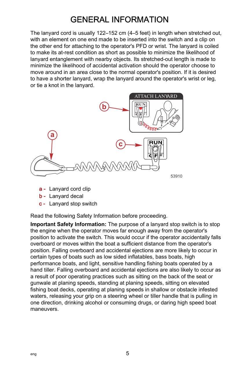
Lanyard Stop Switch The purpose of a lanyard stop switch is to turn off the engine when the operator moves far enough away from the operator's position (as in accidental ejection from the operator's position) to activate the switch. Tiller handle outboards and some remote control units are equipped with a lanyard stop switch. A lanyard stop switch can be installed as an accessory ‑ generally on the dashboard or side adjacent to the operator's position. A decal near the lanyard stop switch is a visual reminder for the operator to attach the lanyard to their personal flotation device (PFD) or wrist.
The lanyard cord is usually 122–152 cm (4–5 feet) in length when stretched out, with an element on one end made to be inserted into the switch and a clip on the other end for attaching to the operator's PFD or wrist. The lanyard is coiled to make its at‑rest condition as short as possible to minimize the likelihood of lanyard entanglement with nearby objects. Its stretched‑out length is made to minimize the likelihood of accidental activation should the operator choose to move around in an area close to the normal operator's position. If it is desired to have a shorter lanyard, wrap the lanyard around the operator's wrist or leg, or tie a knot in the lanyard.
a
ATTACH LANYARD
RUN
b

OFF
c
53910
Read the following Safety Information before proceeding. Important Safety Information: The purpose of a lanyard stop switch is to stop the engine when the operator moves far enough away from the operator's position to activate the switch. This would occur if the operator accidentally falls overboard or moves within the boat a sufficient distance from the operator's position. Falling overboard and accidental ejections are more likely to occur in certain types of boats such as low sided inflatables, bass boats, high performance boats, and light, sensitive handling fishing boats operated by a hand tiller. Falling overboard and accidental ejections are also likely to occur as a result of poor operating practices such as sitting on the back of the seat or gunwale at planing speeds, standing at planing speeds, sitting on elevated fishing boat decks, operating at planing speeds in shallow or obstacle infested waters, releasing your grip on a steering wheel or tiller handle that is pulling in one direction, drinking alcohol or consuming drugs, or daring high speed boat maneuvers.
While activation of the lanyard stop switch will stop the engine immediately, a boat will continue to coast for some distance depending upon the velocity and degree of any turn at shut down. However, the boat will not complete a full circle. While the boat is coasting, it can cause injury to anyone in the boat's path as seriously as the boat would when under power.
We strongly recommend that other occupants be instructed on proper starting and operating procedures should they be required to operate the engine in an emergency (if the operator is accidentally ejected).
||!| |---|
WARNING| |---| |If the operator falls out of the boat, stop the engine immediately to reduce the possibility of serious injury or death from being struck by the boat. Always properly connect the operator to the stop switch using a lanyard.|
||!|
|---|
WARNING| |---| |Avoid serious injury or death from deceleration forces resulting from accidental or unintended stop switch activation. The boat operator should never leave the operator's station without first disconnecting the stop switch lanyard from the operator.|
Accidental or unintended activation of the switch during normal operation is also a possibility. This could cause any, or all, of the following potentially hazardous situations:
########################### KEEP THE LANYARD STOP SWITCH AND LANYARD CORD IN GOOD OPERATING CONDITION
Before each use, check to ensure the lanyard stop switch works properly. Start the engine and stop it by pulling the lanyard cord. If the engine does not stop, have the switch repaired before operating the boat. Before each use, visually inspect the lanyard cord to ensure it is in good working condition and that there are no breaks, cuts, or wear to the cord. Check that the clips on the ends of the cord are in good condition. Replace any damaged or worn lanyard cords.
######################## Protecting People in the Water WHILE YOU ARE CRUISING
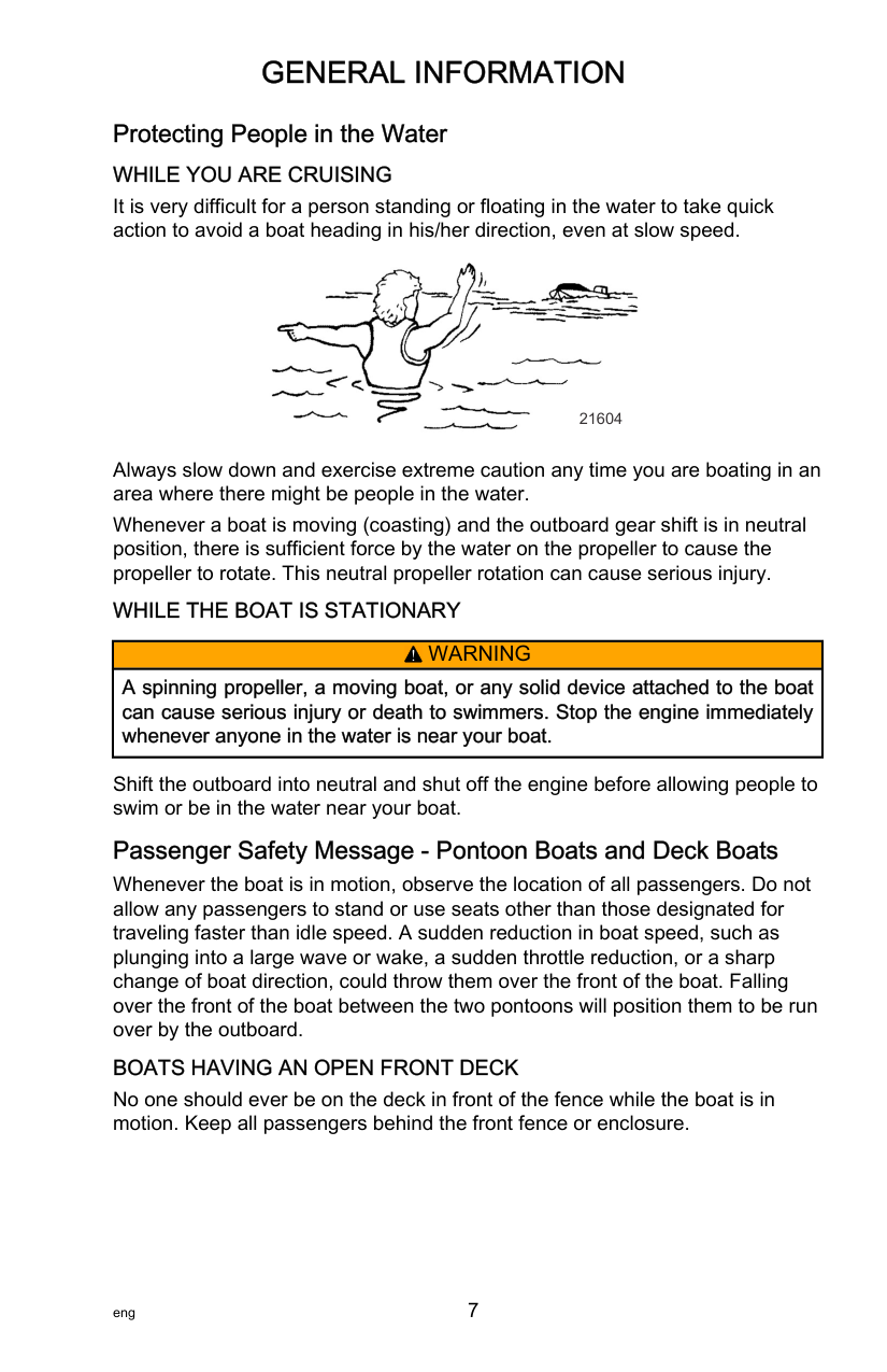
It is very difficult for a person standing or floating in the water to take quick action to avoid a boat heading in his/her direction, even at slow speed.

21604
Always slow down and exercise extreme caution any time you are boating in an area where there might be people in the water. Whenever a boat is moving (coasting) and the outboard gear shift is in neutral position, there is sufficient force by the water on the propeller to cause the propeller to rotate. This neutral propeller rotation can cause serious injury. WHILE THE BOAT IS STATIONARY
||!| |---|
WARNING| |---| |A spinning propeller, a moving boat, or any solid device attached to the boat can cause serious injury or death to swimmers. Stop the engine immediately whenever anyone in the water is near your boat.|
Shift the outboard into neutral and shut off the engine before allowing people to swim or be in the water near your boat.
######################## Passenger Safety Message ‑ Pontoon Boats and Deck Boats
Whenever the boat is in motion, observe the location of all passengers. Do not allow any passengers to stand or use seats other than those designated for traveling faster than idle speed. A sudden reduction in boat speed, such as plunging into a large wave or wake, a sudden throttle reduction, or a sharp change of boat direction, could throw them over the front of the boat. Falling over the front of the boat between the two pontoons will position them to be run over by the outboard.
BOATS HAVING AN OPEN FRONT DECK No one should ever be on the deck in front of the fence while the boat is in motion. Keep all passengers behind the front fence or enclosure.
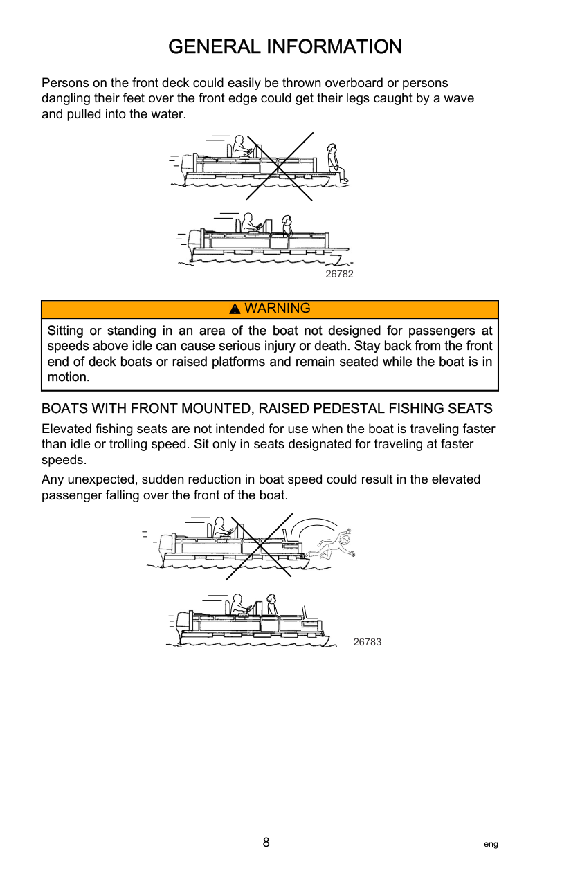
Persons on the front deck could easily be thrown overboard or persons dangling their feet over the front edge could get their legs caught by a wave and pulled into the water.


26782
||!| |---|
WARNING| |---| |Sitting or standing in an area of the boat not designed for passengers at speeds above idle can cause serious injury or death. Stay back from the front end of deck boats or raised platforms and remain seated while the boat is in motion.|
BOATS WITH FRONT MOUNTED, RAISED PEDESTAL FISHING SEATS Elevated fishing seats are not intended for use when the boat is traveling faster than idle or trolling speed. Sit only in seats designated for traveling at faster speeds. Any unexpected, sudden reduction in boat speed could result in the elevated passenger falling over the front of the boat.


26783
######################## Wave and Wake Jumping
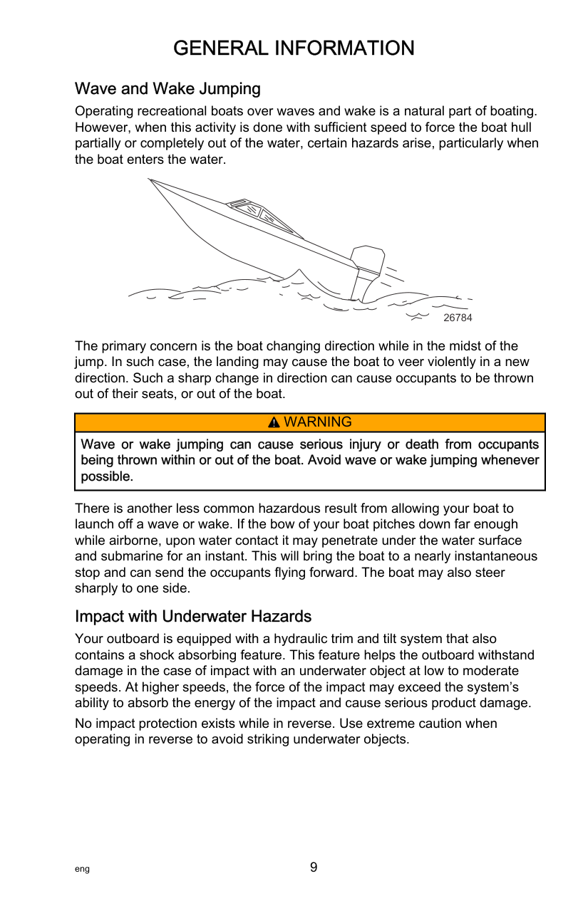
Operating recreational boats over waves and wake is a natural part of boating. However, when this activity is done with sufficient speed to force the boat hull partially or completely out of the water, certain hazards arise, particularly when the boat enters the water.
26784
The primary concern is the boat changing direction while in the midst of the jump. In such case, the landing may cause the boat to veer violently in a new direction. Such a sharp change in direction can cause occupants to be thrown out of their seats, or out of the boat.
||!| |---|
WARNING| |---| |Wave or wake jumping can cause serious injury or death from occupants being thrown within or out of the boat. Avoid wave or wake jumping whenever possible.|
There is another less common hazardous result from allowing your boat to launch off a wave or wake. If the bow of your boat pitches down far enough while airborne, upon water contact it may penetrate under the water surface and submarine for an instant. This will bring the boat to a nearly instantaneous stop and can send the occupants flying forward. The boat may also steer sharply to one side.
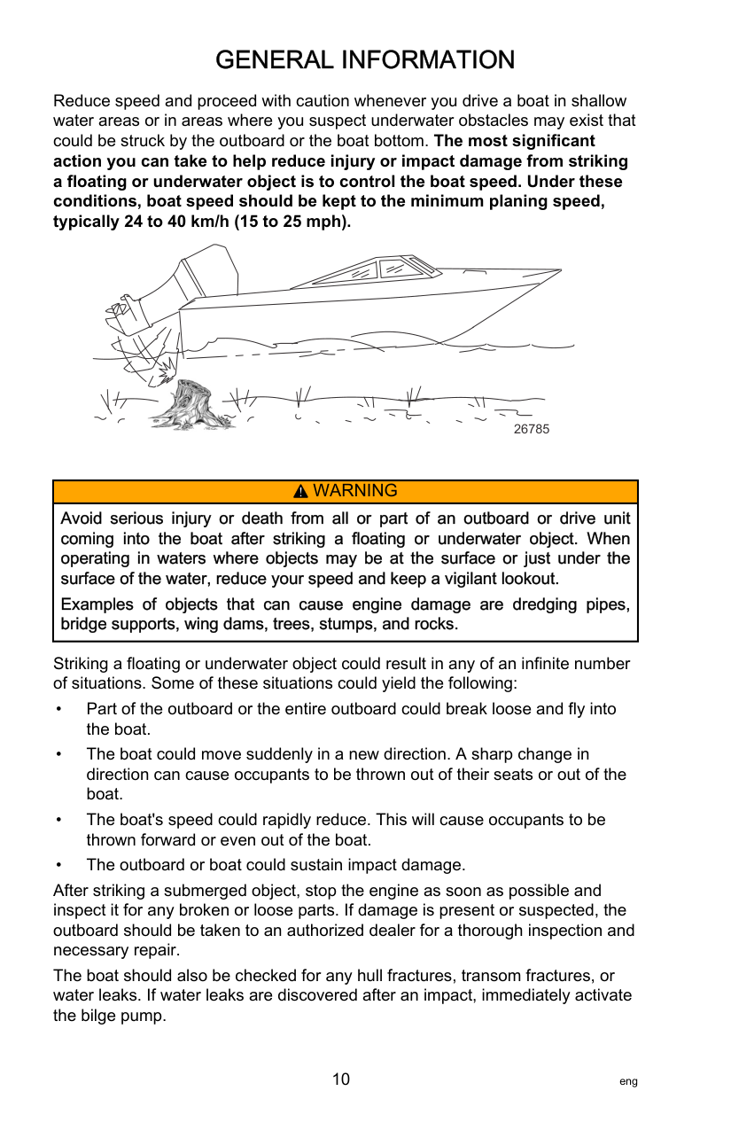
Impact with Underwater Hazards Your outboard is equipped with a hydraulic trim and tilt system that also contains a shock absorbing feature. This feature helps the outboard withstand damage in the case of impact with an underwater object at low to moderate speeds. At higher speeds, the force of the impact may exceed the system’s ability to absorb the energy of the impact and cause serious product damage. No impact protection exists while in reverse. Use extreme caution when operating in reverse to avoid striking underwater objects.
Reduce speed and proceed with caution whenever you drive a boat in shallow water areas or in areas where you suspect underwater obstacles may exist that could be struck by the outboard or the boat bottom. The most significant action you can take to help reduce injury or impact damage from striking a floating or underwater object is to control the boat speed. Under these conditions, boat speed should be kept to the minimum planing speed, typically 24 to 40 km/h (15 to 25 mph).

26785
||!| |---|
WARNING| |---| |Avoid serious injury or death from all or part of an outboard or drive unit coming into the boat after striking a floating or underwater object. When operating in waters where objects may be at the surface or just under the surface of the water, reduce your speed and keep a vigilant lookout.
Examples of objects that can cause engine damage are dredging pipes, bridge supports, wing dams, trees, stumps, and rocks.|
Striking a floating or underwater object could result in any of an infinite number of situations. Some of these situations could yield the following:
After striking a submerged object, stop the engine as soon as possible and inspect it for any broken or loose parts. If damage is present or suspected, the outboard should be taken to an authorized dealer for a thorough inspection and necessary repair. The boat should also be checked for any hull fractures, transom fractures, or water leaks. If water leaks are discovered after an impact, immediately activate the bilge pump.
Operating a damaged outboard could cause additional damage to other parts of the outboard or could affect control of the boat. If continued running is necessary, do so at greatly reduced speeds.
||!| |---|
WARNING| |---| |Operating a boat or engine with impact damage can result in product damage, serious injury, or death. If the vessel experiences any form of impact, have an authorized Mercury Marine dealer inspect and repair the vessel or power package.|
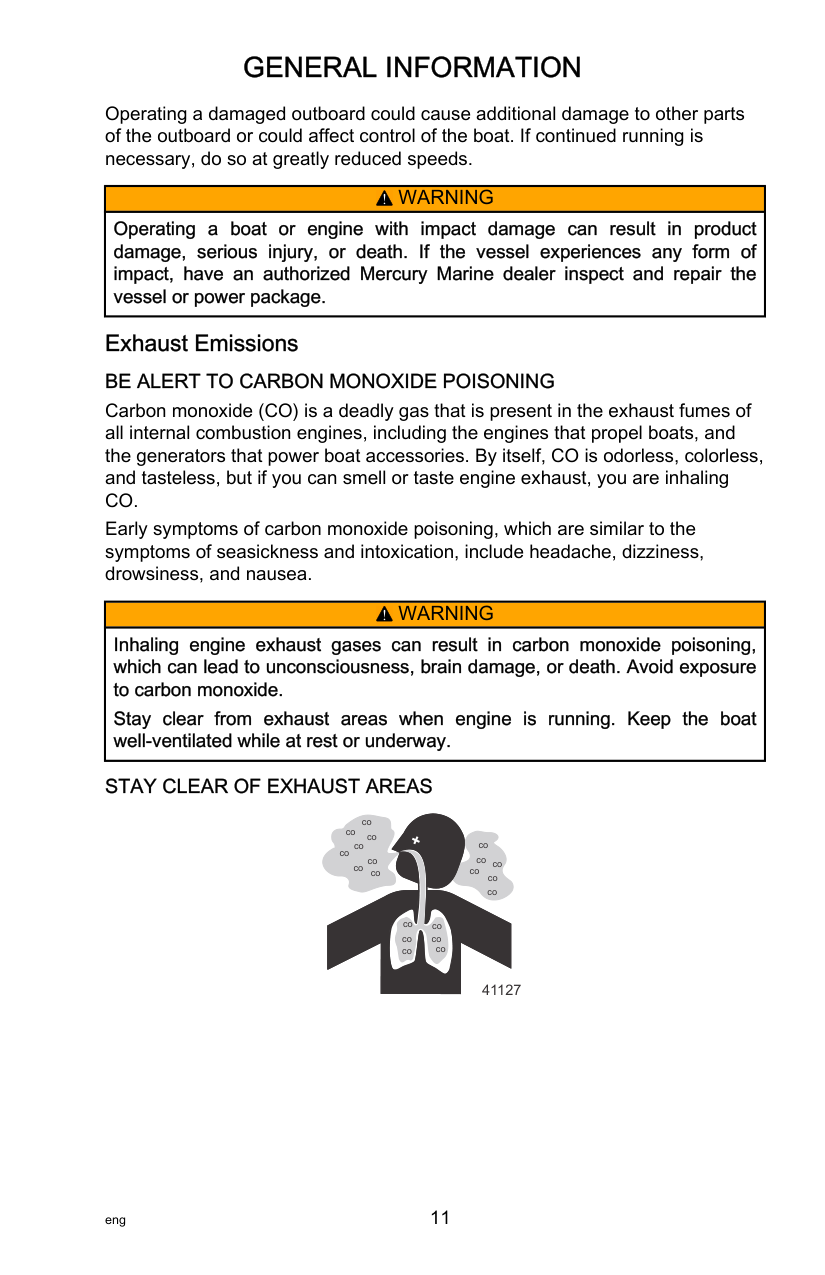
Exhaust Emissions BE ALERT TO CARBON MONOXIDE POISONING Carbon monoxide (CO) is a deadly gas that is present in the exhaust fumes of all internal combustion engines, including the engines that propel boats, and the generators that power boat accessories. By itself, CO is odorless, colorless, and tasteless, but if you can smell or taste engine exhaust, you are inhaling CO. Early symptoms of carbon monoxide poisoning, which are similar to the symptoms of seasickness and intoxication, include headache, dizziness, drowsiness, and nausea.
||!| |---|
WARNING| |---| |Inhaling engine exhaust gases can result in carbon monoxide poisoning, which can lead to unconsciousness, brain damage, or death. Avoid exposure to carbon monoxide.
Stay clear from exhaust areas when engine is running. Keep the boat well‑ventilated while at rest or underway.|
########################### STAY CLEAR OF EXHAUST AREAS
co
co
co
co co
co
co
coco
co
co
co
co
co
co
co
co
co
co
co
41127
Engine exhaust gases contain harmful carbon monoxide. Avoid areas of concentrated engine exhaust gases. When engines are running, keep swimmers away from the boat, and do not sit, lie, or stand on swim platforms or boarding ladders. While underway, do not allow passengers to be positioned immediately behind the boat (platform dragging, teak/body surfing). This dangerous practice not only places a person in an area of high engine exhaust concentration, but also subjects them to the possibility of injury from the boat propeller.
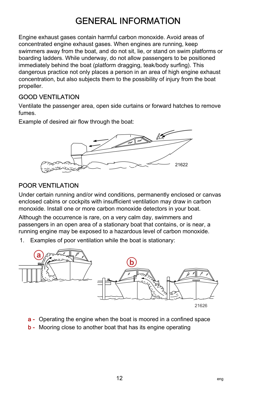
GOOD VENTILATION Ventilate the passenger area, open side curtains or forward hatches to remove fumes. Example of desired air flow through the boat:

POOR VENTILATION Under certain running and/or wind conditions, permanently enclosed or canvas enclosed cabins or cockpits with insufficient ventilation may draw in carbon monoxide. Install one or more carbon monoxide detectors in your boat. Although the occurrence is rare, on a very calm day, swimmers and passengers in an open area of a stationary boat that contains, or is near, a running engine may be exposed to a hazardous level of carbon monoxide. 1. Examples of poor ventilation while the boat is stationary:
a
| | | | | | | |---|---|---|---|---|---| | | | | | | |
| | | |---|---| | | |
b
21626
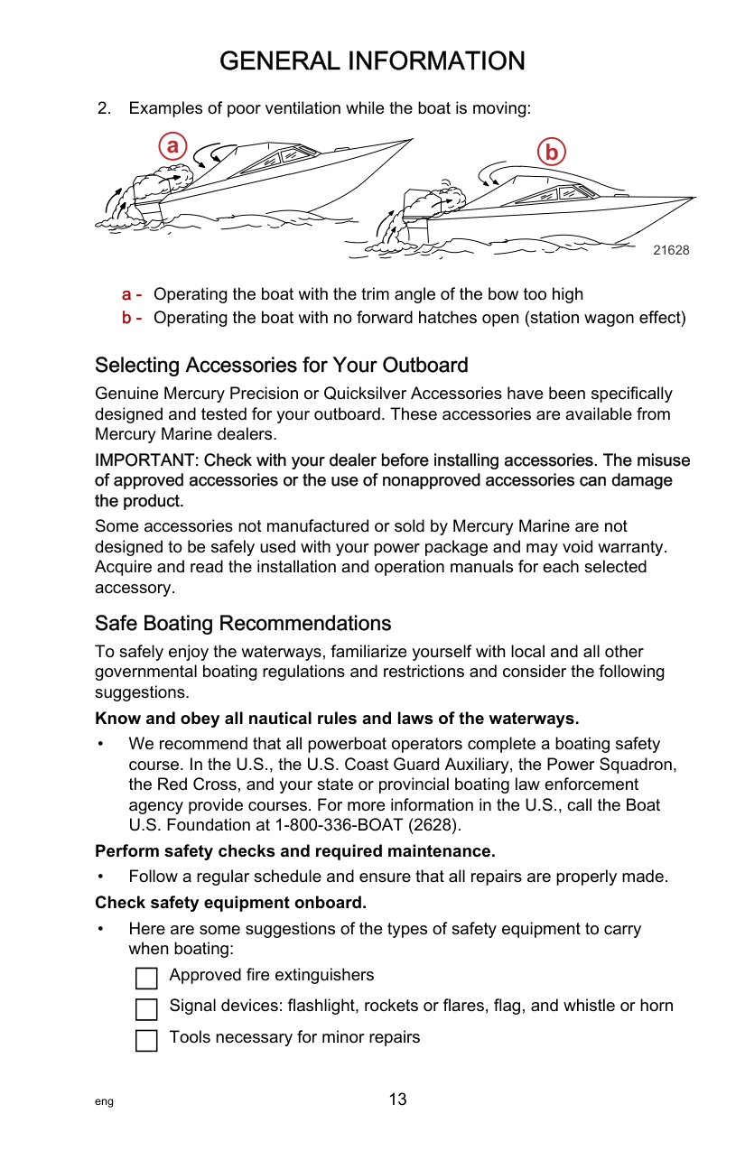
#################### a b
21628
######################## Selecting Accessories for Your Outboard
Genuine Mercury Precision or Quicksilver Accessories have been specifically designed and tested for your outboard. These accessories are available from Mercury Marine dealers.
############################# IMPORTANT: Check with your dealer before installing accessories. The misuse of approved accessories or the use of nonapproved accessories can damage the product.
Some accessories not manufactured or sold by Mercury Marine are not designed to be safely used with your power package and may void warranty. Acquire and read the installation and operation manuals for each selected accessory.
Safe Boating Recommendations To safely enjoy the waterways, familiarize yourself with local and all other governmental boating regulations and restrictions and consider the following suggestions. Know and obey all nautical rules and laws of the waterways.
• We recommend that all powerboat operators complete a boating safety course. In the U.S., the U.S. Coast Guard Auxiliary, the Power Squadron, the Red Cross, and your state or provincial boating law enforcement agency provide courses. For more information in the U.S., call the Boat U.S. Foundation at 1‑800‑336‑BOAT (2628). Perform safety checks and required maintenance.
Approved fire extinguishers Signal devices: flashlight, rockets or flares, flag, and whistle or horn Tools necessary for minor repairs
| | |---|
| | |---|
| | |---|
Anchor and extra anchor line Manual bilge pump and extra drain plugs Drinking water Radio Paddle or oar Spare propeller, thrust hubs, and an appropriate wrench First aid kit and instructions Waterproof storage containers Spare operating equipment, batteries, bulbs, and fuses Compass and map or chart of the area Personal flotation device (one per person onboard)
| | |---|
| | |---|
| | |---|
| | |---|
| | |---|
| | |---|
| | |---|
| | |---|
| | |---|
| |
|---|
| | |---|
Watch for signs of weather change and avoid foul weather and rough‑sea boating. Tell someone where you are going and when you expect to return. Passenger boarding.
• Stop the engine whenever passengers are boarding, unloading, or are near the back (stern) of the boat. Shifting the drive unit into neutral is not sufficient.
############################# Use personal flotation devices.
• Federal law requires that there be a U.S. Coast Guard‑approved life jacket (personal flotation device), correctly sized and readily accessible for every person onboard, plus a throwable cushion or ring. We strongly advise that everyone wear a life jacket at all times while in the boat.
############################# Prepare other boat operators.
• Instruct at least one person onboard in the basics of starting and operating the engine and boat handling in case the driver becomes disabled or falls overboard.
############################# Do not overload your boat.
• Most boats are rated and certified for maximum load (weight) capacities (refer to your boat's capacity plate). Know your boat's operating and loading limitations. Know if your boat will float if it is full of water. When in doubt, contact your authorized Mercury Marine dealer or the boat manufacturer.
############################# Ensure that everyone in the boat is properly seated.
• Do not allow anyone to sit or ride on any part of the boat that was not intended for such use. This includes the backs of seats, gunwales, transom, bow, decks, raised fishing seats, and any rotating fishing seat. Passengers should not sit or ride anywhere that sudden unexpected acceleration, sudden stopping, unexpected loss of boat control, or sudden boat movement could cause a person to be thrown overboard or into the boat. Ensure that all passengers have a proper seat and are in it before any boat movement.
Never operate a boat while under the influence of alcohol or drugs. It is the law.
• Alcohol or drugs can impair your judgment and greatly reduce your ability
to react quickly. Know your boating area and avoid hazardous locations. Be alert.
• The operator of the boat is responsible by law to maintain a proper lookout by sight and hearing. The operator must have an unobstructed view particularly to the front. No passengers, load, or fishing seats should block the operator's view when the boat is above idle or planing transition speed. Watch out for others, the water, and your wake.
############################# Never drive your boat directly behind a water‑skier.
• Your boat traveling at 40 km/h (25 mph) will overtake a fallen skier who is
61 m (200 ft) in front of you in five seconds. Watch fallen skiers.
• When using your boat for waterskiing or similar activities, always keep a fallen or down skier on the operator's side of the boat while returning to attend to the skier. The operator should always have the down skier in sight and never back up to the skier or anyone in the water.
############################# Report accidents.
• Boat operators are required by law to file a boating accident report with their state boating law enforcement agency when their boat is involved in certain boating accidents. A boating accident must be reported if 1) there is loss of life or probable loss of life, 2) there is personal injury requiring medical treatment beyond first aid, 3) there is damage to boats or other property where the damage value exceeds $500.00, or 4) there is complete loss of the boat. Seek further assistance from local law enforcement.
######################## Recording Serial Number
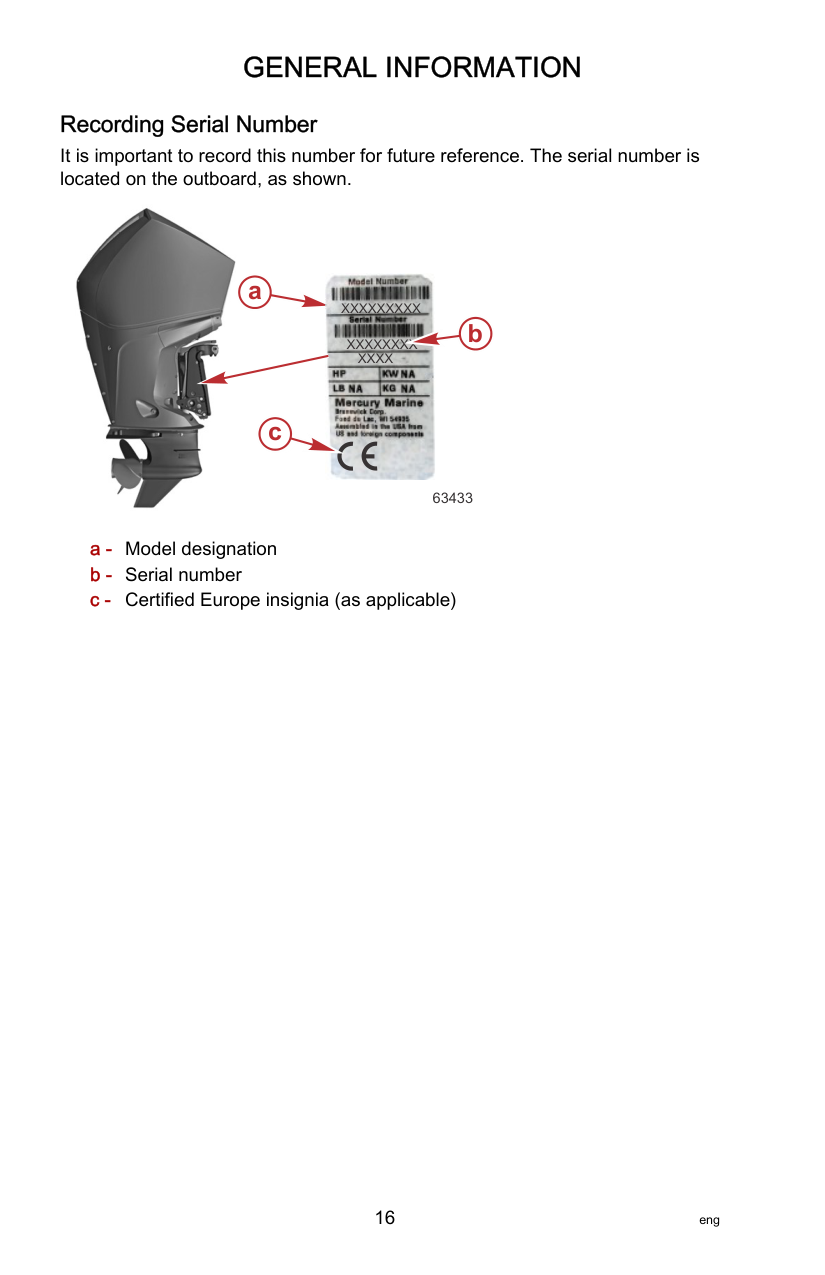
It is important to record this number for future reference. The serial number is located on the outboard, as shown.


############ a
XXXXXXXXX
b
XXXXXXXX XXXX
c
63433
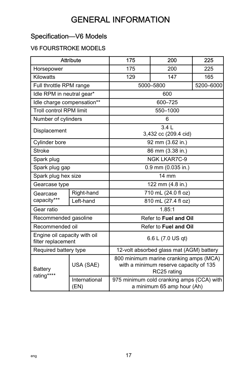
######################## Specification—V6 Models V6 FOURSTROKE MODELS
|Attribute|Attribute|175|200|225| |---|---|---|---|---| |Horsepower|Horsepower|175|200|225| |Kilowatts|Kilowatts|129|147|165|
|Full throttle RPM range|Full throttle RPM range|5000–5800|5000–5800|5200–6000| |Idle RPM in neutral gear*|Idle RPM in neutral gear*|600|600|600| |Idle charge compensation|Idle charge compensation|600–725|600–725|600–725| |Troll control RPM limit|Troll control RPM limit|550–1000|550–1000|550–1000| |Number of cylinders|Number of cylinders|6|6|6| |Displacement|Displacement|3.4 L 3,432 cc (209.4 cid)|3.4 L 3,432 cc (209.4 cid)|3.4 L 3,432 cc (209.4 cid)| |Cylinder bore|Cylinder bore|92 mm (3.62 in.)|92 mm (3.62 in.)|92 mm (3.62 in.)| |Stroke|Stroke|86 mm (3.38 in.)|86 mm (3.38 in.)|86 mm (3.38 in.)| |Spark plug|Spark plug|NGK LKAR7C‑9|NGK LKAR7C‑9|NGK LKAR7C‑9| |Spark plug gap|Spark plug gap|0.9 mm (0.035 in.)|0.9 mm (0.035 in.)|0.9 mm (0.035 in.)| |Spark plug hex size|Spark plug hex size|14 mm|14 mm|14 mm| |Gearcase type|Gearcase type|122 mm (4.8 in.)|122 mm (4.8 in.)|122 mm (4.8 in.)| |Gearcase capacity***|Right‑hand|710 mL (24.0 fl oz)|710 mL (24.0 fl oz)|710 mL (24.0 fl oz)| |Gearcase capacity***|Left‑hand|810 mL (27.4 fl oz)|810 mL (27.4 fl oz)|810 mL (27.4 fl oz)| |Gear ratio|Gear ratio|1.85:1|1.85:1|1.85:1| |Recommended gasoline|Recommended gasoline|Refer to Fuel and Oil|Refer to Fuel and Oil|Refer to Fuel and Oil| |Recommended oil|Recommended oil|Refer to Fuel and Oil|Refer to Fuel and Oil|Refer to Fuel and Oil| |Engine oil capacity with oil filter replacement|Engine oil capacity with oil filter replacement|6.6 L (7.0 US qt)|6.6 L (7.0 US qt)|6.6 L (7.0 US qt)| |Required battery type|Required battery type|12‑volt absorbed glass mat (AGM) battery|12‑volt absorbed glass mat (AGM) battery|12‑volt absorbed glass mat (AGM) battery| |Battery rating****|USA (SAE)|800 minimum marine cranking amps (MCA) with a minimum reserve capacity of 135 RC25 rating|800 minimum marine cranking amps (MCA) with a minimum reserve capacity of 135 RC25 rating|800 minimum marine cranking amps (MCA) with a minimum reserve capacity of 135 RC25 rating| |Battery rating****|International (EN)|975 minimum cold cranking amps (CCA) with a minimum 65 amp hour (Ah)|975 minimum cold cranking amps (CCA) with a minimum 65 amp hour (Ah)|975 minimum cold cranking amps (CCA) with a minimum 65 amp hour (Ah)|
***Early model 4.8 in. gearcase bearing carriers may have the vent located at the 3 o’clock position, requiring a slightly lower volume of gear lubricant.
****Battery manufacturers may rate and test their batteries to different standards. MCA, CCA, Ah, and reserve capacity (RC) are the ratings recognized by Mercury Marine. Manufacturers that use standards different than these, such as equivalent MCA, do not meet Mercury Marine battery requirements.
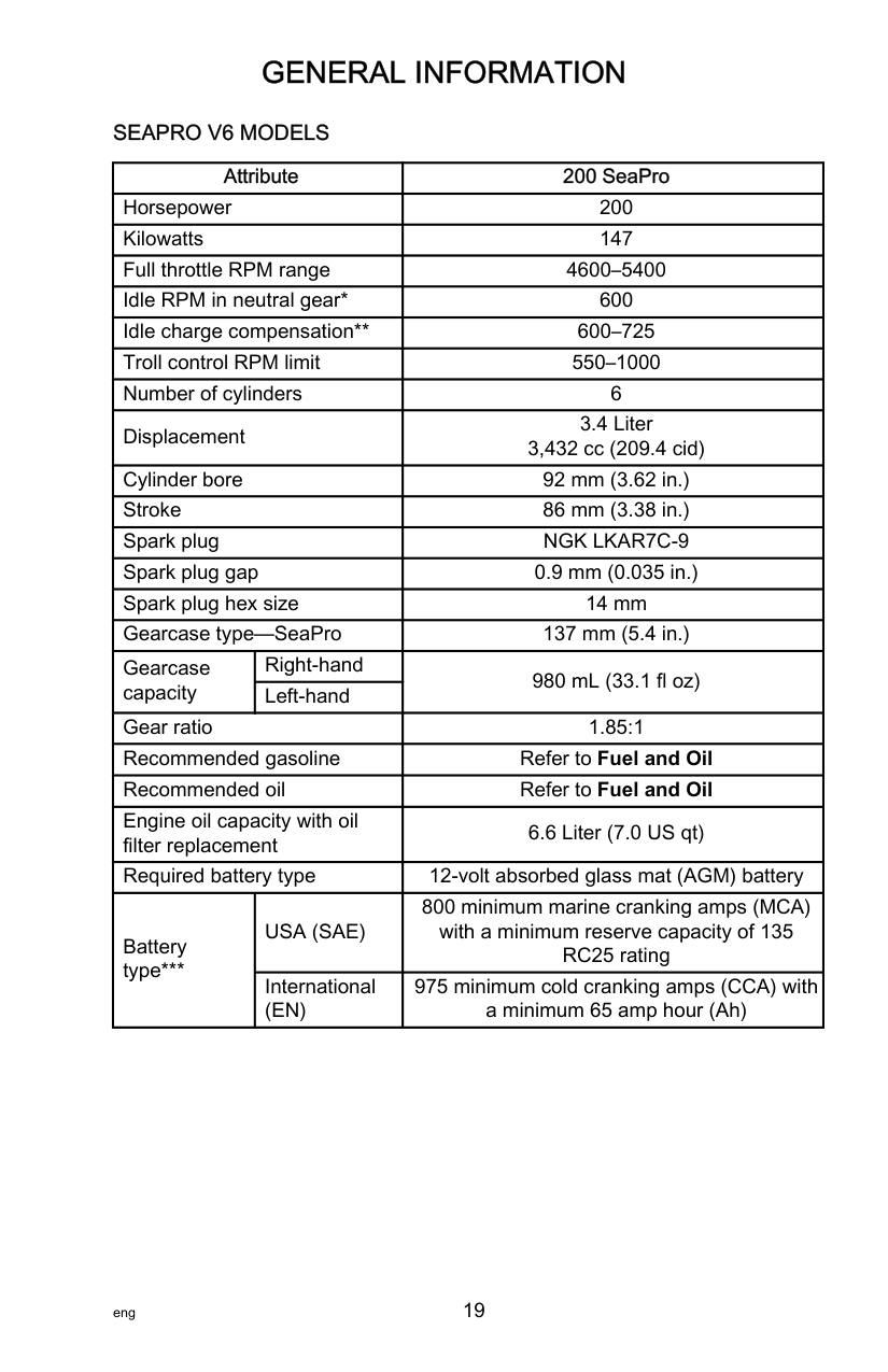
########################### SEAPRO V6 MODELS
|Attribute|Attribute|200 SeaPro| |---|---|---| |Horsepower|Horsepower|200| |Kilowatts|Kilowatts|147| |Full throttle RPM range|Full throttle RPM range|4600–5400| |Idle RPM in neutral gear*|Idle RPM in neutral gear*|600| |Idle charge compensation|Idle charge compensation|600–725| |Troll control RPM limit|Troll control RPM limit|550–1000| |Number of cylinders|Number of cylinders|6| |Displacement|Displacement|3.4 Liter 3,432 cc (209.4 cid)| |Cylinder bore|Cylinder bore|92 mm (3.62 in.)| |Stroke|Stroke|86 mm (3.38 in.)| |Spark plug|Spark plug|NGK LKAR7C‑9| |Spark plug gap|Spark plug gap|0.9 mm (0.035 in.)| |Spark plug hex size|Spark plug hex size|14 mm| |Gearcase type—SeaPro|Gearcase type—SeaPro|137 mm (5.4 in.)| |Gearcase capacity|Right‑hand|980 mL (33.1 fl oz)| |Gearcase capacity|Left‑hand|980 mL (33.1 fl oz)| |Gear ratio|Gear ratio|1.85:1| |Recommended gasoline|Recommended gasoline|Refer to Fuel and Oil| |Recommended oil|Recommended oil|Refer to Fuel and Oil| |Engine oil capacity with oil filter replacement|Engine oil capacity with oil filter replacement|6.6 Liter (7.0 US qt)| |Required battery type|Required battery type|12‑volt absorbed glass mat (AGM) battery|
|Battery type***|USA (SAE)|800 minimum marine cranking amps (MCA) with a minimum reserve capacity of 135 RC25 rating| |Battery type***|International (EN)|975 minimum cold cranking amps (CCA) with a minimum 65 amp hour (Ah)|
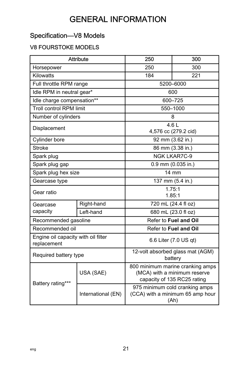
######################## Specification—V8 Models V8 FOURSTOKE MODELS
|Attribute|Attribute|250|300| |---|---|---|---| |Horsepower|Horsepower|250|300| |Kilowatts|Kilowatts|184|221| |Full throttle RPM range|Full throttle RPM range|5200–6000|5200–6000| |Idle RPM in neutral gear*|Idle RPM in neutral gear*|600|600| |Idle charge compensation|Idle charge compensation|600–725|600–725| |Troll control RPM limit|Troll control RPM limit|550–1000|550–1000| |Number of cylinders|Number of cylinders|8|8| |Displacement|Displacement|4.6 L 4,576 cc (279.2 cid)|4.6 L 4,576 cc (279.2 cid)| |Cylinder bore|Cylinder bore|92 mm (3.62 in.)|92 mm (3.62 in.)| |Stroke|Stroke|86 mm (3.38 in.)|86 mm (3.38 in.)| |Spark plug|Spark plug|NGK LKAR7C‑9|NGK LKAR7C‑9| |Spark plug gap|Spark plug gap|0.9 mm (0.035 in.)|0.9 mm (0.035 in.)| |Spark plug hex size|Spark plug hex size|14 mm|14 mm| |Gearcase type|Gearcase type|137 mm (5.4 in.)|137 mm (5.4 in.)| |Gear ratio|Gear ratio|1.75:1 1.85:1|1.75:1 1.85:1| |Gearcase capacity|Right‑hand|720 mL (24.4 fl oz)|720 mL (24.4 fl oz)| |Gearcase capacity|Left‑hand|680 mL (23.0 fl oz)|680 mL (23.0 fl oz)| |Recommended gasoline|Recommended gasoline|Refer to Fuel and Oil|Refer to Fuel and Oil|

|Recommended oil|Recommended oil|Refer to Fuel and Oil|Refer to Fuel and Oil| |Engine oil capacity with oil filter replacement|Engine oil capacity with oil filter replacement|6.6 Liter (7.0 US qt)|6.6 Liter (7.0 US qt)| |Required battery type|Required battery type|12‑volt absorbed glass mat (AGM) battery|12‑volt absorbed glass mat (AGM) battery| |Battery rating***|USA (SAE)|800 minimum marine cranking amps (MCA) with a minimum reserve capacity of 135 RC25 rating|800 minimum marine cranking amps (MCA) with a minimum reserve capacity of 135 RC25 rating| |Battery rating***|International (EN)|975 minimum cold cranking amps (CCA) with a minimum 65 amp hour (Ah)|975 minimum cold cranking amps (CCA) with a minimum 65 amp hour (Ah)|
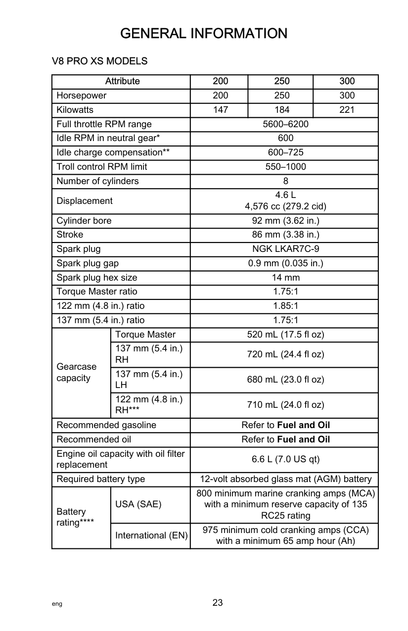
########################### V8 PRO XS MODELS
|Attribute|Attribute|200|250|300| |---|---|---|---|---| |Horsepower|Horsepower|200|250|300| |Kilowatts|Kilowatts|147|184|221| |Full throttle RPM range|Full throttle RPM range|5600–6200|5600–6200|5600–6200| |Idle RPM in neutral gear*|Idle RPM in neutral gear*|600|600|600| |Idle charge compensation|Idle charge compensation|600–725|600–725|600–725| |Troll control RPM limit|Troll control RPM limit|550–1000|550–1000|550–1000| |Number of cylinders|Number of cylinders|8|8|8| |Displacement|Displacement|4.6 L 4,576 cc (279.2 cid)|4.6 L 4,576 cc (279.2 cid)|4.6 L 4,576 cc (279.2 cid)| |Cylinder bore|Cylinder bore|92 mm (3.62 in.)|92 mm (3.62 in.)|92 mm (3.62 in.)| |Stroke|Stroke|86 mm (3.38 in.)|86 mm (3.38 in.)|86 mm (3.38 in.)| |Spark plug|Spark plug|NGK LKAR7C‑9|NGK LKAR7C‑9|NGK LKAR7C‑9| |Spark plug gap|Spark plug gap|0.9 mm (0.035 in.)|0.9 mm (0.035 in.)|0.9 mm (0.035 in.)| |Spark plug hex size|Spark plug hex size|14 mm|14 mm|14 mm| |Torque Master ratio|Torque Master ratio|1.75:1|1.75:1|1.75:1| |122 mm (4.8 in.) ratio|122 mm (4.8 in.) ratio|1.85:1|1.85:1|1.85:1|
|137 mm (5.4 in.) ratio|137 mm (5.4 in.) ratio|1.75:1|1.75:1|1.75:1| |Gearcase capacity|Torque Master|520 mL (17.5 fl oz)|520 mL (17.5 fl oz)|520 mL (17.5 fl oz)| |Gearcase capacity|137 mm (5.4 in.) RH|720 mL (24.4 fl oz)|720 mL (24.4 fl oz)|720 mL (24.4 fl oz)| |Gearcase capacity|137 mm (5.4 in.) LH|680 mL (23.0 fl oz)|680 mL (23.0 fl oz)|680 mL (23.0 fl oz)| |Gearcase capacity|122 mm (4.8 in.) RH***|710 mL (24.0 fl oz)|710 mL (24.0 fl oz)|710 mL (24.0 fl oz)| |Recommended gasoline|Recommended gasoline|Refer to Fuel and Oil|Refer to Fuel and Oil|Refer to Fuel and Oil| |Recommended oil|Recommended oil|Refer to Fuel and Oil|Refer to Fuel and Oil|Refer to Fuel and Oil| |Engine oil capacity with oil filter replacement|Engine oil capacity with oil filter replacement|6.6 L (7.0 US qt)|6.6 L (7.0 US qt)|6.6 L (7.0 US qt)| |Required battery type|Required battery type|12‑volt absorbed glass mat (AGM) battery|12‑volt absorbed glass mat (AGM) battery|12‑volt absorbed glass mat (AGM) battery| |Battery rating****|USA (SAE)|800 minimum marine cranking amps (MCA) with a minimum reserve capacity of 135 RC25 rating|800 minimum marine cranking amps (MCA) with a minimum reserve capacity of 135 RC25 rating|800 minimum marine cranking amps (MCA) with a minimum reserve capacity of 135 RC25 rating| |Battery rating****|International (EN)|975 minimum cold cranking amps (CCA) with a minimum 65 amp hour (Ah)|975 minimum cold cranking amps (CCA) with a minimum 65 amp hour (Ah)|975 minimum cold cranking amps (CCA) with a minimum 65 amp hour (Ah)|
***Early model 4.8 in. gearcase bearing carriers may have the lubricant level plug located at the 3 o’clock position, requiring a slightly lower volume of gear lubricant.
****Battery manufacturers may rate and test their batteries to different standards. MCA, CCA, Ah, and reserve capacity (RC) are the ratings recognized by Mercury Marine. Manufacturers that use standards different than these, such as equivalent MCA, do not meet Mercury Marine battery requirements.
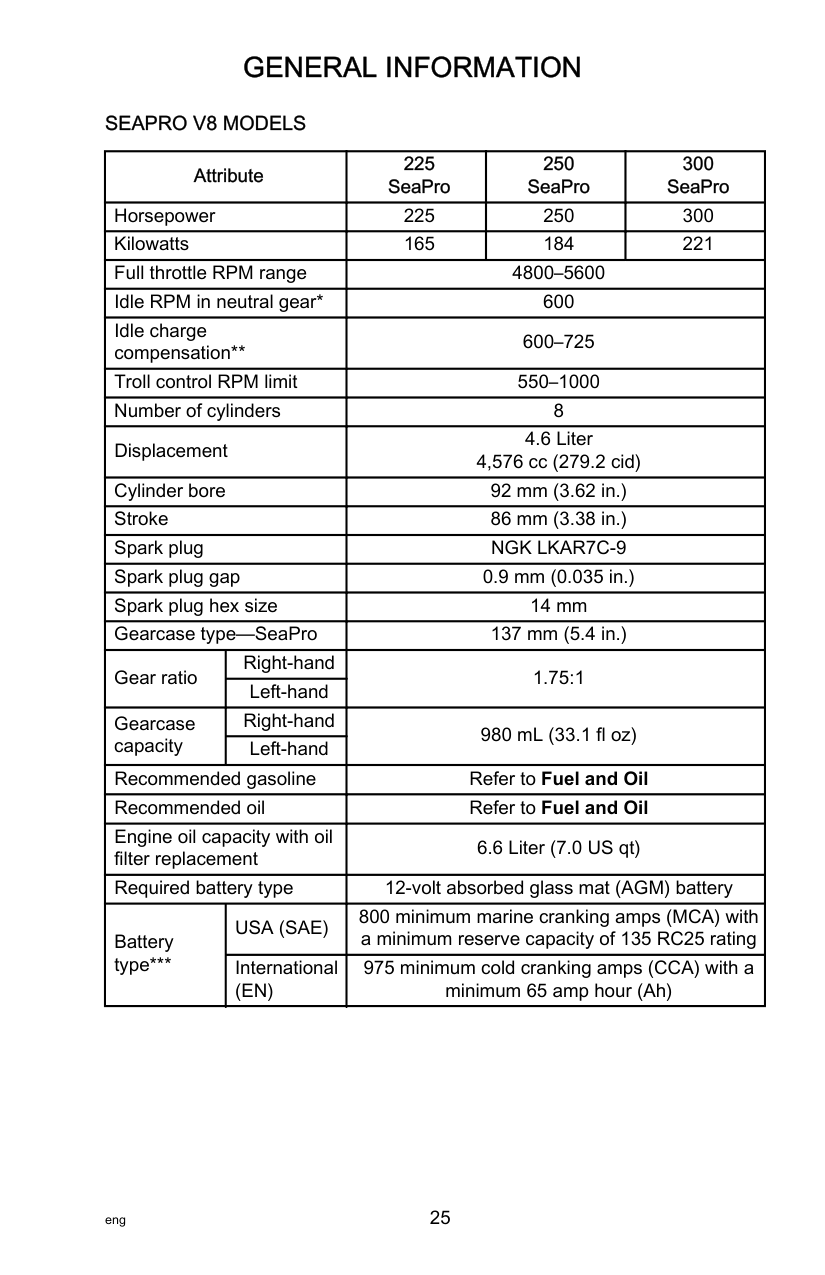
########################### SEAPRO V8 MODELS
|Attribute|Attribute|225 SeaPro|250 SeaPro|300 SeaPro| |---|---|---|---|---| |Horsepower|Horsepower|225|250|300| |Kilowatts|Kilowatts|165|184|221| |Full throttle RPM range|Full throttle RPM range|4800–5600|4800–5600|4800–5600| |Idle RPM in neutral gear*|Idle RPM in neutral gear*|600|600|600| |Idle charge compensation|Idle charge compensation|600–725|600–725|600–725|

|Troll control RPM limit|Troll control RPM limit|550–1000|550–1000|550–1000| |Number of cylinders|Number of cylinders|8|8|8| |Displacement|Displacement|4.6 Liter 4,576 cc (279.2 cid)|4.6 Liter 4,576 cc (279.2 cid)|4.6 Liter 4,576 cc (279.2 cid)| |Cylinder bore|Cylinder bore|92 mm (3.62 in.)|92 mm (3.62 in.)|92 mm (3.62 in.)| |Stroke|Stroke|86 mm (3.38 in.)|86 mm (3.38 in.)|86 mm (3.38 in.)| |Spark plug|Spark plug|NGK LKAR7C‑9|NGK LKAR7C‑9|NGK LKAR7C‑9| |Spark plug gap|Spark plug gap|0.9 mm (0.035 in.)|0.9 mm (0.035 in.)|0.9 mm (0.035 in.)| |Spark plug hex size|Spark plug hex size|14 mm|14 mm|14 mm| |Gearcase type—SeaPro|Gearcase type—SeaPro|137 mm (5.4 in.)|137 mm (5.4 in.)|137 mm (5.4 in.)| |Gear ratio|Right‑hand|1.75:1|1.75:1|1.75:1| |Gear ratio|Left‑hand|1.75:1|1.75:1|1.75:1| |Gearcase capacity|Right‑hand|980 mL (33.1 fl oz)|980 mL (33.1 fl oz)|980 mL (33.1 fl oz)| |Gearcase capacity|Left‑hand|980 mL (33.1 fl oz)|980 mL (33.1 fl oz)|980 mL (33.1 fl oz)| |Recommended gasoline|Recommended gasoline|Refer to Fuel and Oil|Refer to Fuel and Oil|Refer to Fuel and Oil| |Recommended oil|Recommended oil|Refer to Fuel and Oil|Refer to Fuel and Oil|Refer to Fuel and Oil| |Engine oil capacity with oil filter replacement|Engine oil capacity with oil filter replacement|6.6 Liter (7.0 US qt)|6.6 Liter (7.0 US qt)|6.6 Liter (7.0 US qt)| |Required battery type|Required battery type|12‑volt absorbed glass mat (AGM) battery|12‑volt absorbed glass mat (AGM) battery|12‑volt absorbed glass mat (AGM) battery| |Battery type***|USA (SAE)|800 minimum marine cranking amps (MCA) with a minimum reserve capacity of 135 RC25 rating|800 minimum marine cranking amps (MCA) with a minimum reserve capacity of 135 RC25 rating|800 minimum marine cranking amps (MCA) with a minimum reserve capacity of 135 RC25 rating| |Battery type***|International (EN)|975 minimum cold cranking amps (CCA) with a minimum 65 amp hour (Ah)|975 minimum cold cranking amps (CCA) with a minimum 65 amp hour (Ah)|975 minimum cold cranking amps (CCA) with a minimum 65 amp hour (Ah)|
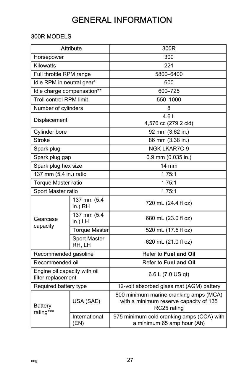
########################### 300R MODELS
|Attribute|Attribute|300R| |---|---|---| |Horsepower|Horsepower|300|
|Kilowatts|Kilowatts|221| |Full throttle RPM range|Full throttle RPM range|5800–6400| |Idle RPM in neutral gear*|Idle RPM in neutral gear*|600| |Idle charge compensation|Idle charge compensation|600–725| |Troll control RPM limit|Troll control RPM limit|550–1000| |Number of cylinders|Number of cylinders|8| |Displacement|Displacement|4.6 L 4,576 cc (279.2 cid)| |Cylinder bore|Cylinder bore|92 mm (3.62 in.)| |Stroke|Stroke|86 mm (3.38 in.)| |Spark plug|Spark plug|NGK LKAR7C‑9| |Spark plug gap|Spark plug gap|0.9 mm (0.035 in.)| |Spark plug hex size|Spark plug hex size|14 mm| |137 mm (5.4 in.) ratio|137 mm (5.4 in.) ratio|1.75:1| |Torque Master ratio|Torque Master ratio|1.75:1| |Sport Master ratio|Sport Master ratio|1.75:1| |Gearcase capacity|137 mm (5.4 in.) RH|720 mL (24.4 fl oz)| |Gearcase capacity|137 mm (5.4 in.) LH|680 mL (23.0 fl oz)| |Gearcase capacity|Torque Master|520 mL (17.5 fl oz)| |Gearcase capacity|Sport Master RH, LH|620 mL (21.0 fl oz)| |Recommended gasoline|Recommended gasoline|Refer to Fuel and Oil| |Recommended oil|Recommended oil|Refer to Fuel and Oil| |Engine oil capacity with oil filter replacement|Engine oil capacity with oil filter replacement|6.6 L (7.0 US qt)| |Required battery type|Required battery type|12‑volt absorbed glass mat (AGM) battery| |Battery rating***|USA (SAE)|800 minimum marine cranking amps (MCA) with a minimum reserve capacity of 135 RC25 rating| |Battery rating***|International (EN)|975 minimum cold cranking amps (CCA) with a minimum 65 amp hour (Ah)|

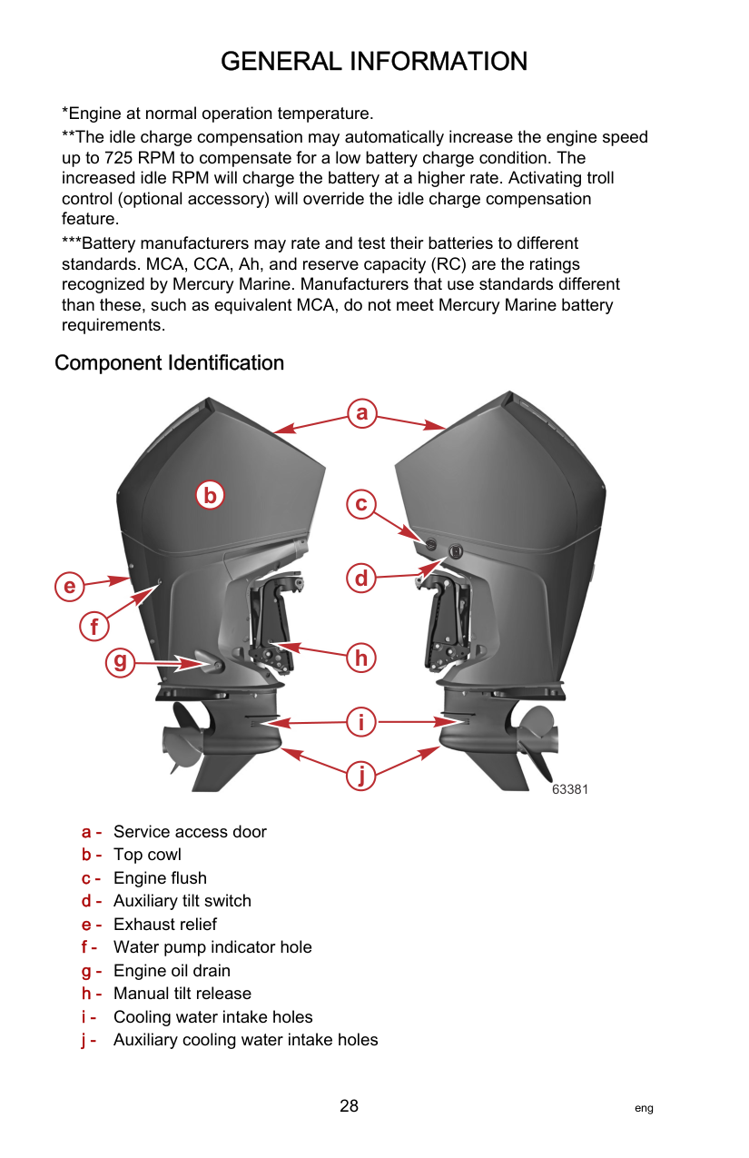
######################## Component Identification


a
b c
de
63381
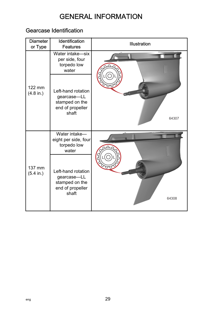
######################## Gearcase Identification
|Diameter or Type|Identification Features|Illustration| |---|---|---| |122 mm (4.8 in.)|Water intake—six per side, four torpedo low
water
|
L L
64307| |122 mm (4.8 in.)|Left‑hand rotation gearcase—LL stamped on the end of propeller shaft|
L L
64307| |137 mm (5.4 in.)|Water intakeeight per side, four torpedo low
water|
L L
64308| |137 mm (5.4 in.)|Left‑hand rotation gearcase—LL stamped on the end of propeller shaft|
L L
64308|
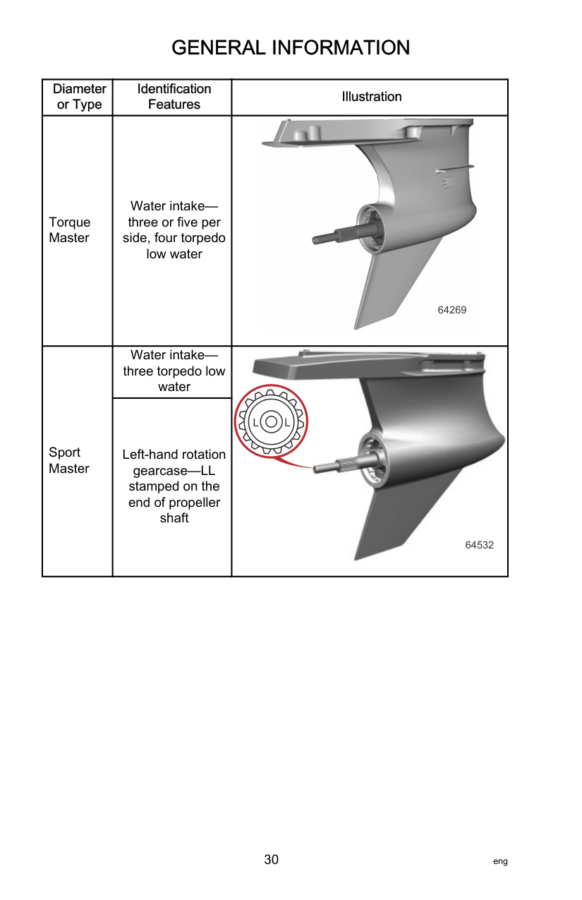
|Diameter or Type|Identification Features|Illustration| |---|---|---| |Torque Master|Water intakethree or five per side, four torpedo low water|
64269| |Sport Master|Water intakethree torpedo low water
|
64532
L L| |Sport Master|Left‑hand rotation gearcase—LL stamped on the end of propeller shaft|
64532
L L|

######################## Aquatic Invasive Species (AIS)

############################# STOP AQUATIC HITCHHIKERS!™ Be A Good Steward. Clean. Drain. Dry.
For additional information, visit StopAquaticHitchhikers.org.
AIS and their spread can detrimentally impact the boating experience and the future of the boating lifestyle. Reducing the spread of AIS has led to significant national efforts to inspect boats moving between water bodies or across state and federal boundaries and could lead to delayed or denied access if AIS are suspected or found on board. AIS include plant life such as Eurasian watermilfoil and water hyacinth, and animals such as spiny water flea, quagga, and zebra mussels. AIS may vary in size from microscopic, to easily visible to the naked eye, and can live in residual water or mud. These species damage ecosystems and negatively impact fishing by depleting natural food resources, altering the water environment, and changing the structure of the ecosystem. The impact of AIS has already resulted in the limiting of boating access to many waterways throughout North America, the closure of public boat ramps, and the reduction of availability for fishing and boating across the United States. Many federal, state, and local agencies have enacted laws and regulations for inspections, permits, launch availability, and water access for vessels entering public waterways. Boats and associated equipment are major contributors to the spread of AIS. Boats that have come into contact with AIS can become a means of transportation through attachment and entrapment. You should be aware that water passes in and out of the space under the lower cowls on your engine during normal operation of the boat. When flushing and cleaning your boat to control the spread of AIS, pay attention to this space by directing flushing water into the spaces under the lower cowl. The engine cooling system can be flushed by operating the engine with the appropriate flushing attachment and introducing heated water to the engine.
For more information about the control of AIS in your area, please contact your area wildlife conservation office or local governmental natural resources office.
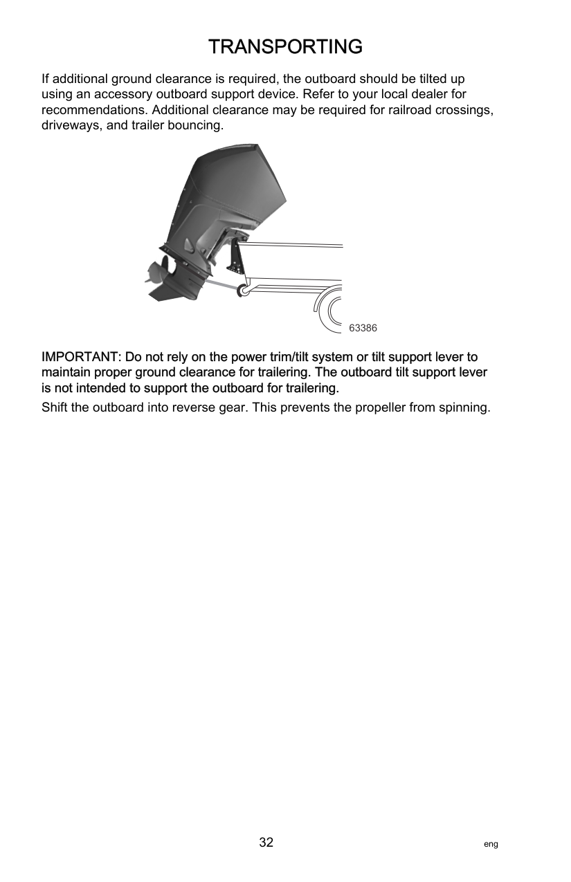
Trailering Boat/Outboard Trailer your boat with the outboard tilted down in a vertical operating position.
If additional ground clearance is required, the outboard should be tilted up using an accessory outboard support device. Refer to your local dealer for recommendations. Additional clearance may be required for railroad crossings, driveways, and trailer bouncing.


63386
############################# IMPORTANT: Do not rely on the power trim/tilt system or tilt support lever to maintain proper ground clearance for trailering. The outboard tilt support lever is not intended to support the outboard for trailering. Shift the outboard into reverse gear. This prevents the propeller from spinning.
Fuel Requirements
IMPORTANT: Use of improper gasoline can damage your engine. Engine damage resulting from the use of improper gasoline is considered misuse of the engine and will not be covered under the limited warranty.
FUEL RATINGS Mercury outboard engines will operate satisfactorily with any major brand of unleaded gasoline that meets the following specifications: USA and Canada ‑ A posted pump octane rating of 87 (R+M)/2, minimum, for most models. Premium gasoline 91 (R+M)/2 octane is also acceptable for most models. Do not use leaded gasoline. Outside USA and Canada ‑ A posted pump octane rating of 91 RON, minimum, for most models. Premium gasoline (95 RON) is also acceptable for all models. Do not use leaded gasoline. USING REFORMULATED (OXYGENATED) GASOLINE (USA ONLY)
Reformulated gasoline is required in certain areas of the USA and is acceptable for use in your Mercury Marine engine. The only oxygenate currently in use in the USA is alcohol (ethanol, methanol, or butanol).
########################### GASOLINE CONTAINING ALCOHOL Bu16 Butanol Fuel Blends
Fuel blends of up to 16.1% butanol (Bu16) that meet the published Mercury Marine fuel rating requirements are an acceptable substitute for unleaded gasoline. Contact your boat manufacturer for specific recommendations on your boat's fuel system components (fuel tanks, fuel lines, and fittings).
Methanol and Ethanol Fuel Blends IMPORTANT: The fuel system components on your Mercury Marine engine will withstand up to 10% alcohol (methanol or ethanol) content in the gasoline. Your boat's fuel system may not be capable of withstanding the same percentage of alcohol. Contact your boat manufacturer for specific recommendations on your boat's fuel system components (fuel tanks, fuel lines, and fittings). Be aware that gasoline containing methanol or ethanol may cause increased:
||!| |---|
WARNING| |---| |Fuel leakage is a fire or explosion hazard, which can cause serious injury or death. Periodically inspect all fuel system components for leaks, softening, hardening, swelling, or corrosion, particularly after storage. Any sign of leakage or deterioration requires replacement before further engine operation.|

IMPORTANT: If you use gasoline that contains or might contain methanol or ethanol, you must increase the frequency of inspection for leaks and abnormalities. IMPORTANT: When operating a Mercury Marine engine on gasoline containing methanol or ethanol, do not store the gasoline in the fuel tank for long periods. Cars normally consume these blended fuels before they can absorb enough moisture to cause trouble; boats often sit idle long enough for phase separation to take place. Internal corrosion may occur during storage if alcohol has washed protective oil films from internal components.
######################## Fuel Additives
To minimize carbon deposit buildup in the engine, add Mercury or Quicksilver Quickleen Engine and Fuel System Cleaner to the engine's fuel at each tank throughout the boating season. Use the additive as directed on the container.
######################## Low Permeation Fuel Hose Requirement
Required for outboards manufactured for sale, sold, or offered for sale in the United States.
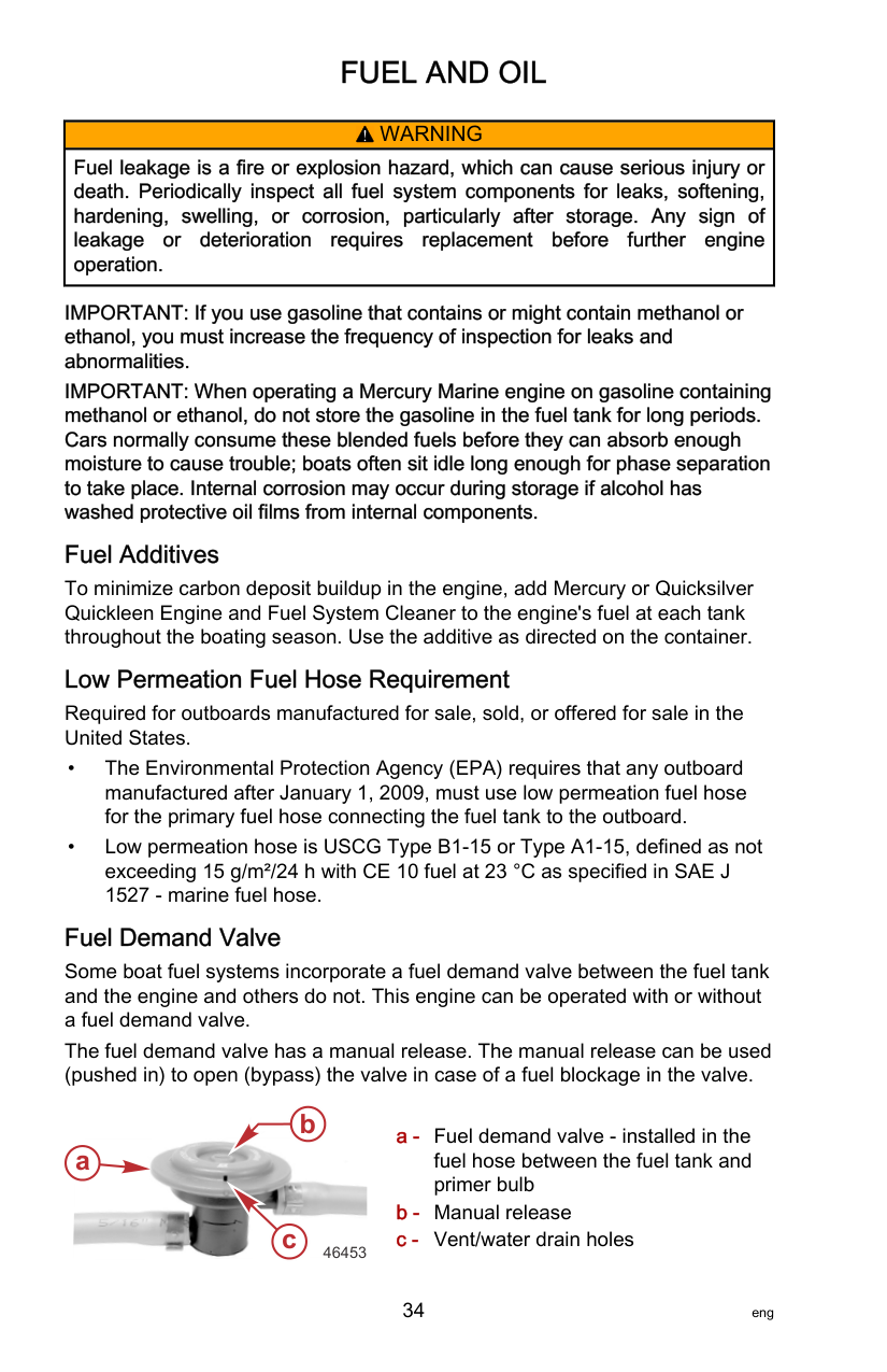
Fuel Demand Valve Some boat fuel systems incorporate a fuel demand valve between the fuel tank and the engine and others do not. This engine can be operated with or without a fuel demand valve. The fuel demand valve has a manual release. The manual release can be used (pushed in) to open (bypass) the valve in case of a fuel blockage in the valve.
b

a
c
46453
######################## Engine Oil Recommendations—Standard, Pro XS, and Race (R) Models
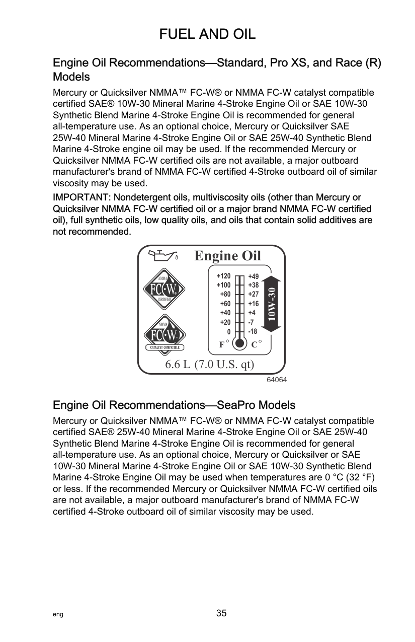
Mercury or Quicksilver NMMA™ FC‑W® or NMMA FC‑W catalyst compatible certified SAE® 10W‑30 Mineral Marine 4‑Stroke Engine Oil or SAE 10W‑30 Synthetic Blend Marine 4‑Stroke Engine Oil is recommended for general all‑temperature use. As an optional choice, Mercury or Quicksilver SAE 25W‑40 Mineral Marine 4‑Stroke Engine Oil or SAE 25W‑40 Synthetic Blend Marine 4‑Stroke engine oil may be used. If the recommended Mercury or Quicksilver NMMA FC‑W certified oils are not available, a major outboard manufacturer's brand of NMMA FC‑W certified 4‑Stroke outboard oil of similar viscosity may be used.
IMPORTANT: Nondetergent oils, multiviscosity oils (other than Mercury or Quicksilver NMMA FC‑W certified oil or a major brand NMMA FC‑W certified oil), full synthetic oils, low quality oils, and oils that contain solid additives are not recommended.
Engine Oil
+120 +49
+100 +80 +60 +40 +20
+38 +27 +16 +4
########################## 10W-30 64064
0
C
F
##################### 6.6 L (7.0 U.S. qt)
######################## Engine Oil Recommendations—SeaPro Models
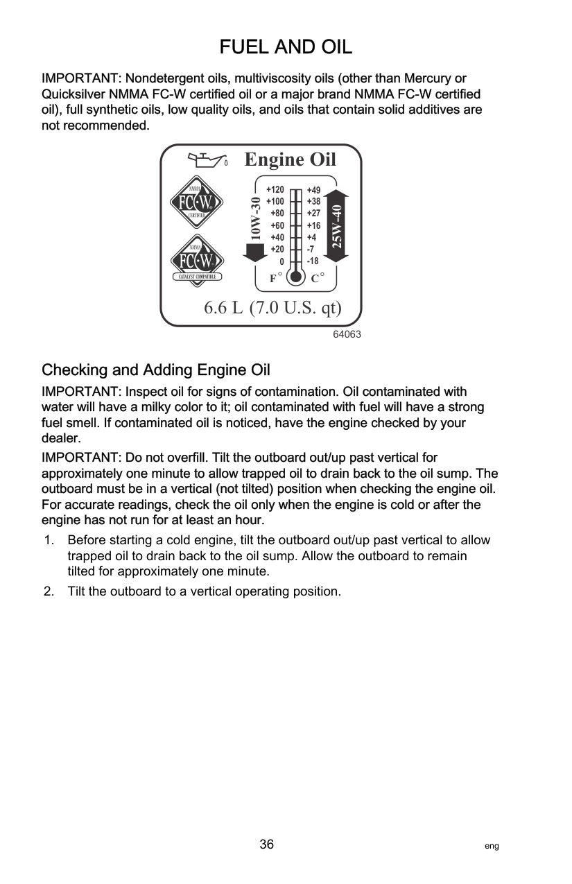
Mercury or Quicksilver NMMA™ FC‑W® or NMMA FC‑W catalyst compatible certified SAE® 25W‑40 Mineral Marine 4‑Stroke Engine Oil or SAE 25W‑40 Synthetic Blend Marine 4‑Stroke Engine Oil is recommended for general all‑temperature use. As an optional choice, Mercury or Quicksilver or SAE 10W‑30 Mineral Marine 4‑Stroke Engine Oil or SAE 10W‑30 Synthetic Blend Marine 4‑Stroke Engine Oil may be used when temperatures are 0 °C (32 °F) or less. If the recommended Mercury or Quicksilver NMMA FC‑W certified oils are not available, a major outboard manufacturer's brand of NMMA FC‑W certified 4‑Stroke outboard oil of similar viscosity may be used.
IMPORTANT: Nondetergent oils, multiviscosity oils (other than Mercury or Quicksilver NMMA FC‑W certified oil or a major brand NMMA FC‑W certified oil), full synthetic oils, low quality oils, and oils that contain solid additives are not recommended.
Engine Oil
+120 +49
+100 +80 +60 +40 +20
+38 +27 +16 +4
10W-30
25W-40
0
C
F
6.6 L (7.0 U.S. qt)
64063
Checking and Adding Engine Oil IMPORTANT: Inspect oil for signs of contamination. Oil contaminated with water will have a milky color to it; oil contaminated with fuel will have a strong fuel smell. If contaminated oil is noticed, have the engine checked by your dealer. IMPORTANT: Do not overfill. Tilt the outboard out/up past vertical for approximately one minute to allow trapped oil to drain back to the oil sump. The outboard must be in a vertical (not tilted) position when checking the engine oil. For accurate readings, check the oil only when the engine is cold or after the engine has not run for at least an hour.

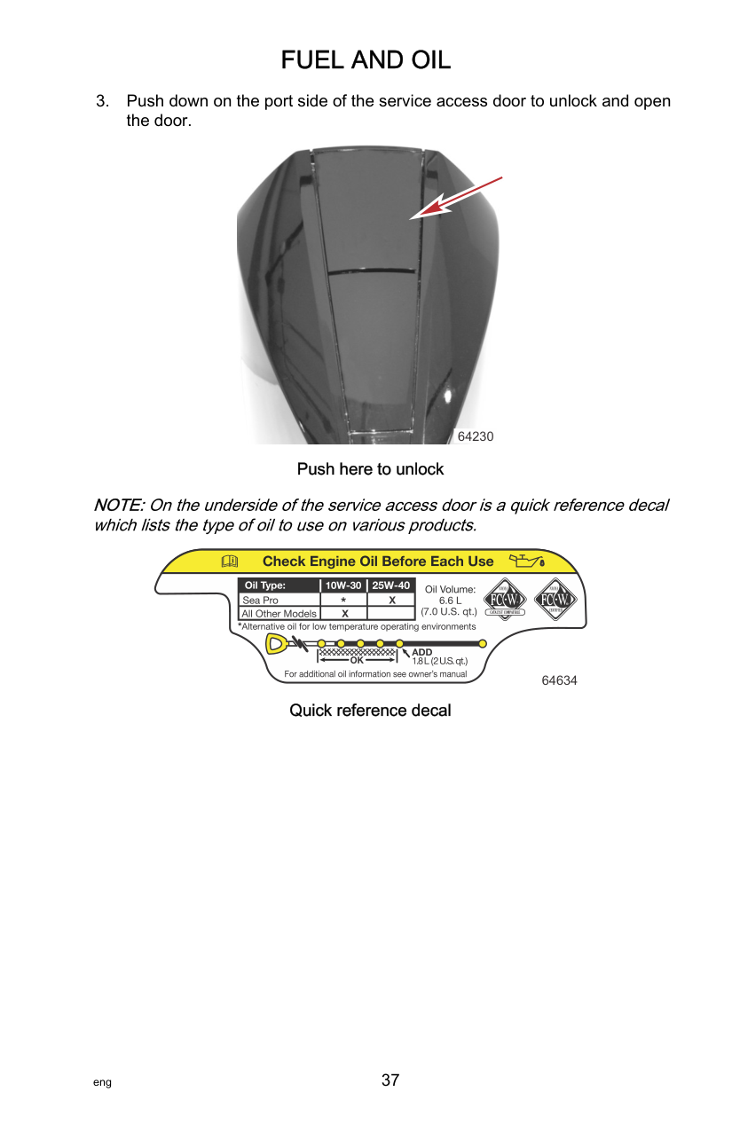
64230 Push here to unlock
NOTE:On the underside of the service access door is a quick reference decal which lists the type of oil to use on various products.
| | | | |---|---|---| | | | | | | | |
64634 Quick reference decal

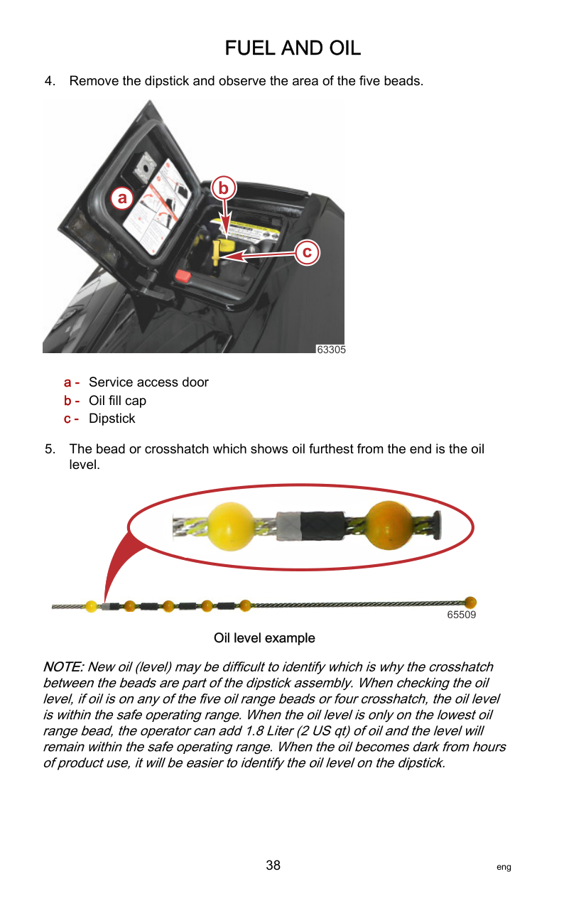
b
a
c


63305


65509 Oil level example
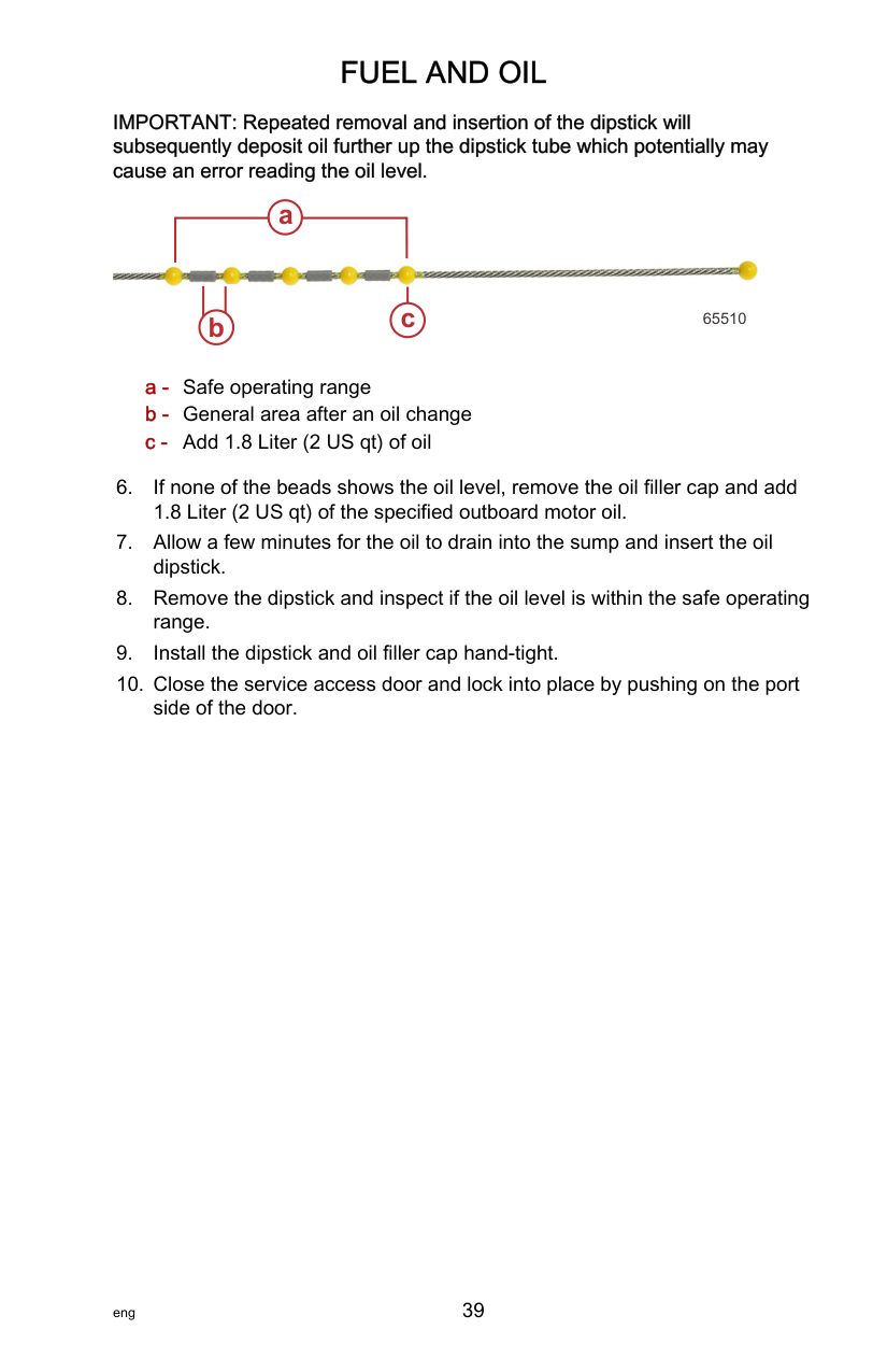
NOTE:New oil (level) may be difficult to identify which is why the crosshatch between the beads are part of the dipstick assembly. When checking the oil level, if oil is on any of the five oil range beads or four crosshatch, the oil level is within the safe operating range. When the oil level is only on the lowest oil range bead, the operator can add 1.8 Liter (2 US qt) of oil and the level will remain within the safe operating range. When the oil becomes dark from hours of product use, it will be easier to identify the oil level on the dipstick.

#### FUEL AND OIL
############################# IMPORTANT: Repeated removal and insertion of the dipstick will subsequently deposit oil further up the dipstick tube which potentially may cause an error reading the oil level.
a
c
b 65510
######################## Adaptive Speed Control
This outboard package utilizes adaptive speed control which automatically adjusts the engine load (throttle) to maintain engine speed (RPM). For example, when the boat operator steers into a hard turn, which results in increased load on the engine and a loss of RPM, the propulsion control module (PCM) will open the throttle to maintain RPM through the turn, without the need for the operator to increase the remote control throttle handle. Another example is when cruising or utilizing the boat for tow sports, engine speed will remain constant, regardless of load changes due to waves, trim position, turning or load changes from tow sports. Adaptive speed control is active from idle RPM up to max rated RPM, however, can only maintain engine speed when the throttle is less than wide open.
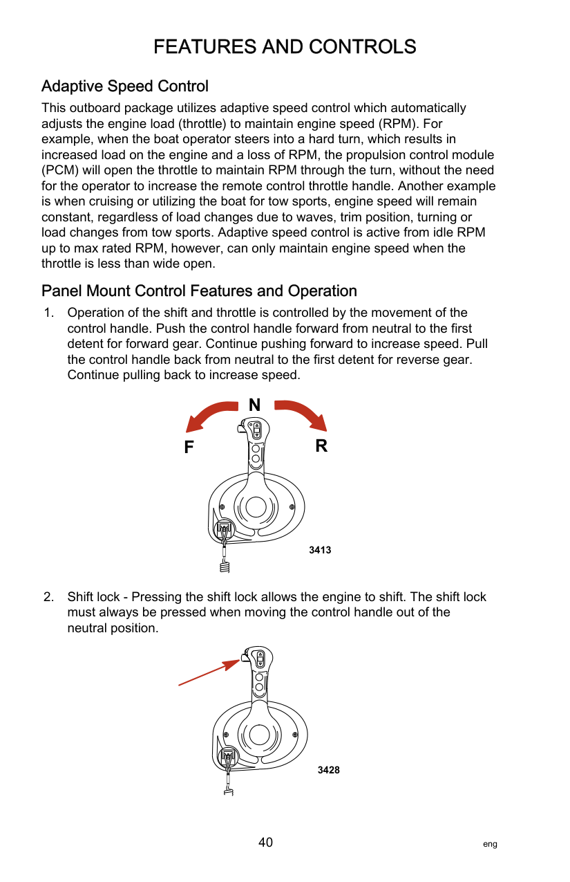
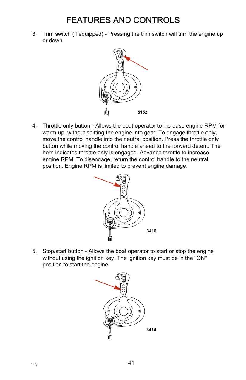
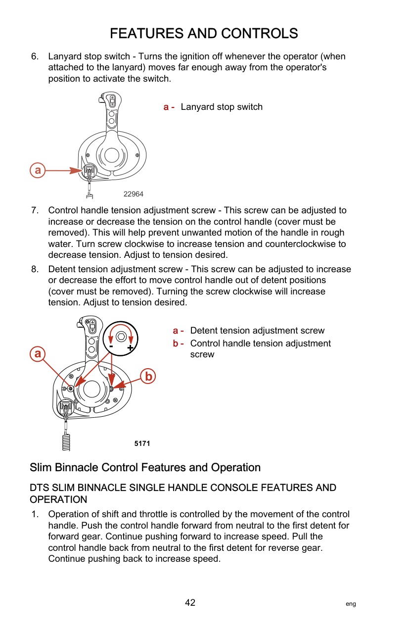
######################## Panel Mount Control Features and Operation
F
N
R
3413
3428
5152
3416
3414
a - Lanyard stop switch
###################### a
22964
+a
##### b
5171
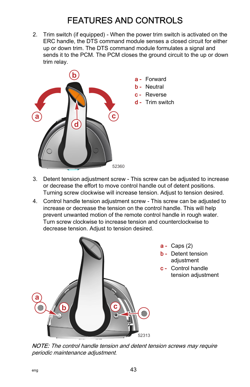
Slim Binnacle Control Features and Operation
DTS SLIM BINNACLE SINGLE HANDLE CONSOLE FEATURES AND OPERATION
b

c d
a
52360

###### a
###### b c
52313
NOTE:The control handle tension and detent tension screws may require periodic maintenance adjustment.
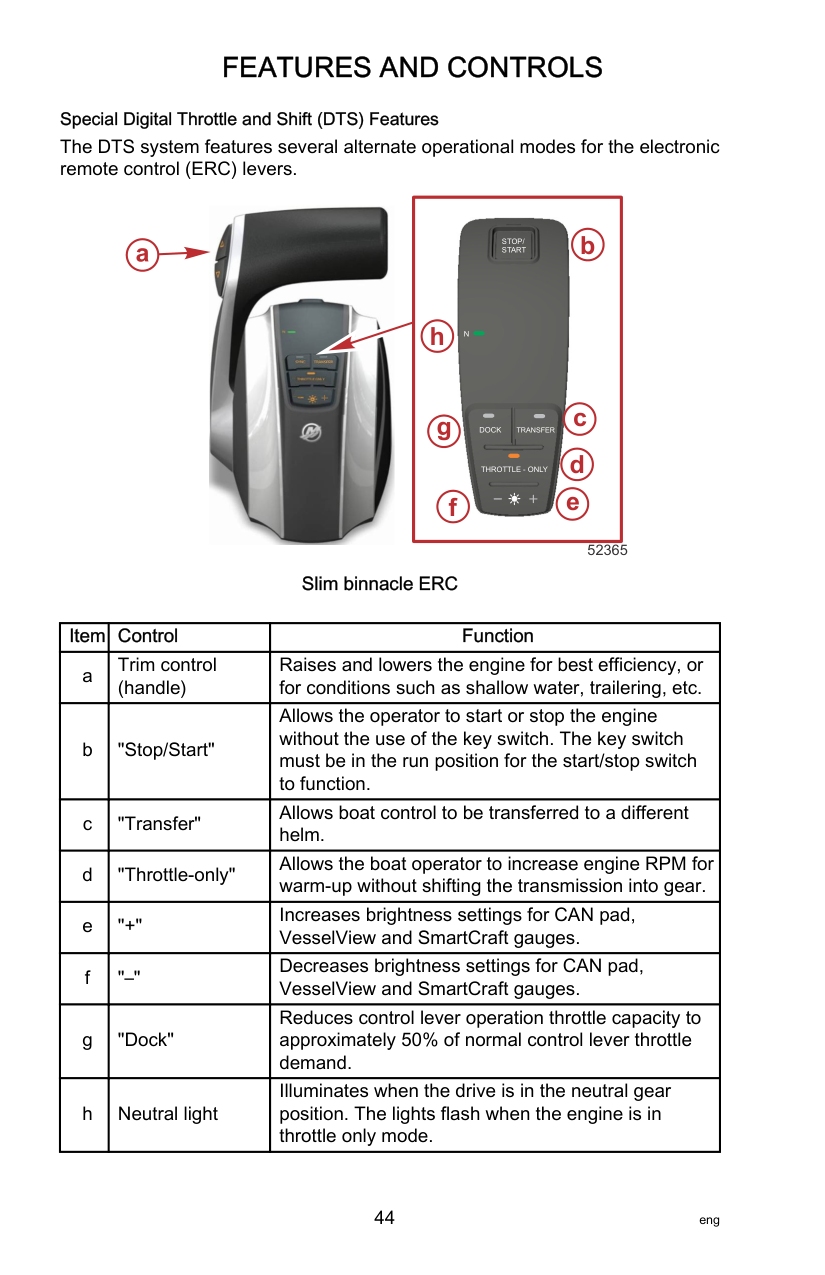
Special Digital Throttle and Shift (DTS) Features The DTS system features several alternate operational modes for the electronic remote control (ERC) levers.
|
STOP/ START
THROTTLE - ONLY
DOCK TRANSFER
N
b
c
d
ef
g
h
| |---|


############################# 52365 Slim binnacle ERC
|Item|Control|Function| |---|---|---| |a|Trim control (handle)|Raises and lowers the engine for best efficiency, or for conditions such as shallow water, trailering, etc.| |b|"Stop/Start"|Allows the operator to start or stop the engine without the use of the key switch. The key switch must be in the run position for the start/stop switch to function.|
|c|"Transfer"|Allows boat control to be transferred to a different helm.| |d|"Throttle‑only"|Allows the boat operator to increase engine RPM for warm‑up without shifting the transmission into gear.| |e|"+"|Increases brightness settings for CAN pad, VesselView and SmartCraft gauges.| |f|"–"|Decreases brightness settings for CAN pad, VesselView and SmartCraft gauges.| |g|"Dock"|Reduces control lever operation throttle capacity to approximately 50% of normal control lever throttle demand.| |h|Neutral light|Illuminates when the drive is in the neutral gear position. The lights flash when the engine is in throttle only mode.|
HELM TRANSFER Some boats are designed to allow control of the vessel from more than one location. These locations are commonly referred to as helms or stations. Helm transfer is a term used to describe the method of transferring control from one helm (or station) to another helm.
||!| |---|
WARNING| |---| |Avoid serious injury or death from loss of boat control. The boat operator should never leave the active station while engine is in gear. Helm transfer should only be attempted while both stations are manned. One‑person helm transfer should only be performed while engine is in neutral.|
The helm transfer function allows the boat operator to select which helm is in control of the vessel. Before a transfer can be initiated the ERC levers at the active helm and at the helm intended for the transfer must be in the neutral position. NOTE:If you attempt to transfer helm control when the ERC levers are not in neutral, a beep will sound and the helm transfer will not succeed until the levers at the helms are moved to neutral and transfer is requested again.
Some fault codes may appear on VesselView if other control or navigation functions are attempted after the helm transfer procedure is started. To remove the fault codes it may be necessary to cycle the key switch OFF and ON, and then restart the helm transfer procedure. Ensure that other control and navigation inputs are performed after helm transfer is complete to avoid setting fault codes.
|NOTICE| |---| |The ERC levers must be in neutral to perform a helm transfer. While in neutral your vessel could drift and collide with objects nearby resulting in damage. Keep an adequate look out while performing the helm transfer.|
To avoid damage, use extra care when attempting a helm transfer while the vessel is close to docks, piers, or other fixed items or when near other vessels.
REQUESTING HELM TRANSFER NOTE:Any movement of the ERC levers after pressing the transfer button terminates the helm transfer request. A single beep sounds and the transfer button light turns off signaling the end of the transfer request. To request the transfer of vessel control from one helm to another:
#### FEATURES AND CONTROLS

THROTTLE - ONLY
DOCK TRANSFER
52367 "Transfer" button
NOTE:If the ERC levers at the helms are not in neutral, the neutral lights will flash. Move all the ERC levers to neutral and the neutral light will stop flashing.
NOTE:If the helm transfer is not completed in 10 seconds, the request is automatically cancelled, a double beep sounds and control will remain at the existing active helm. Press the transfer button again to start the helm transfer.

THROTTLE-ONLY Throttle‑only allows the operator to increase the engine RPM for warm‑up without shifting the engine into gear. To engage throttle‑only mode:
DOCK TRANSFER
THROTTLE - ONLY
############################# 52373 "Throttle-Only" button
NOTE:Pressing the "Throttle‑Only" button while the ERC lever is not in the neutral position, turns the button light off and remains in throttle‑only mode. You must place the ERC lever into the neutral position to disengage throttle‑only mode. To disengage throttle‑only mode:

DOCK Dock mode reduces throttle capacity to approximately 50% of normal throttle demand, allowing finer control of engine power in close quarter situations. If more power is needed for vessel maneuvering when environmental conditions require more thrust, disable dock mode to return the engine control to full thrust capability.
DOCK TRANSFER
THROTTLE - ONLY
############################# 52372 "DOCK" button
######################## Dual‑Handle Console Control Features and Operation DUAL-HANDLE ELECTRONIC REMOTE CONTROL (ERC)OPERATION AND ADJUSTMENT
Operation The electronic remote control (ERC) handle controls the shift and throttle operation. Push the control handle forward from neutral to the first detent for forward gear. Continue pushing the handle forward to increase speed. Pull the control handle from the forward position to the neutral position to decrease speed and eventually stop. Pull the control handle back from neutral to the first detent for reverse gear. Continue pulling the handle back to increase speed in reverse.
b

a
c
51902
The amount of force needed to move the handles and to move the handles through the detents is adjustable to help prevent unwanted motion.
Adjustment NOTE:The control handle tension and detent tension may require periodic maintenance using the adjustment screws. To adjust the handle detent tension:
To adjust handle tension:

############## a b
51901
SPECIAL DIGITAL THROTTLE AND SHIFT (DTS) FEATURES The DTS system features several alternate operational modes for the electronic remote control (ERC) levers. Any of the listed features can operate simultaneously.

############### a

f
55232
Dual engine ERC
|Item|Control|Function| |---|---|---| |a|Trim control (handle)|Raises and lowers the engines for best efficiency, or for conditions such as shallow water, trailering, etc.| |b|NEUTRAL lights|Illuminate when the drive is in the neutral gear position. The lights flash when the engine is in throttle only mode.| |c|TRANSFER|Allows boat control to be transferred to a different helm. Refer to Helm Transfer.| |d|DOCK|Control lever operation reduces throttle capacity to approximately 50% of normal control lever throttle demand.| |e|+|Increases brightness settings for CAN pad, VesselView and SmartCraft gauges.| |f|THROTTLE ONLY|Allows the boat operator to increase engine RPM for warm‑up without shifting the transmission into gear.| |g|–|Decreases brightness settings for CAN pad, VesselView and SmartCraft gauges.|
|Item|Control|Function| |---|---|---| |h|1 LEVER|Enables the throttle and shift functions of both engines to be controlled by the port lever.| |i|SYNC|Turns off or on the auto‑synchronization feature. Refer to Sync.|
NOTE:Not all functions may be active. Dock
Dock mode reduces throttle capacity to approximately 50% of normal throttle demand, allowing finer control of engine power in close quarter situations.

51854
DOCK button
Throttle Only NOTE:Throttle only mode should be used if the captain is not in command at the helm. Placing the ERC in throttle only mode will avoid unintended gear engagement. The engines will turn using the steering wheel and the RPM of the engines can be increased while in the throttle only mode, but the gear position will remain in neutral.

51855
THROTTLE ONLY button To engage throttle only mode:
NOTE:Pressing the THROTTLE ONLY button while the ERC levers are not in the neutral position, turns the button light off and remains in throttle only mode. You must place the ERC levers into the neutral position to disengage throttle only mode. To disengage throttle only mode:
This feature commands both engines with a single lever on a dual engine application. This feature simplifies engine management during rough sea conditions by allowing you to use a single lever to command both engines simultaneously. It is not the same as the system feature called Sync.

51856
1 LEVER button To engage 1 Lever mode:
To disengage 1 Lever mode:
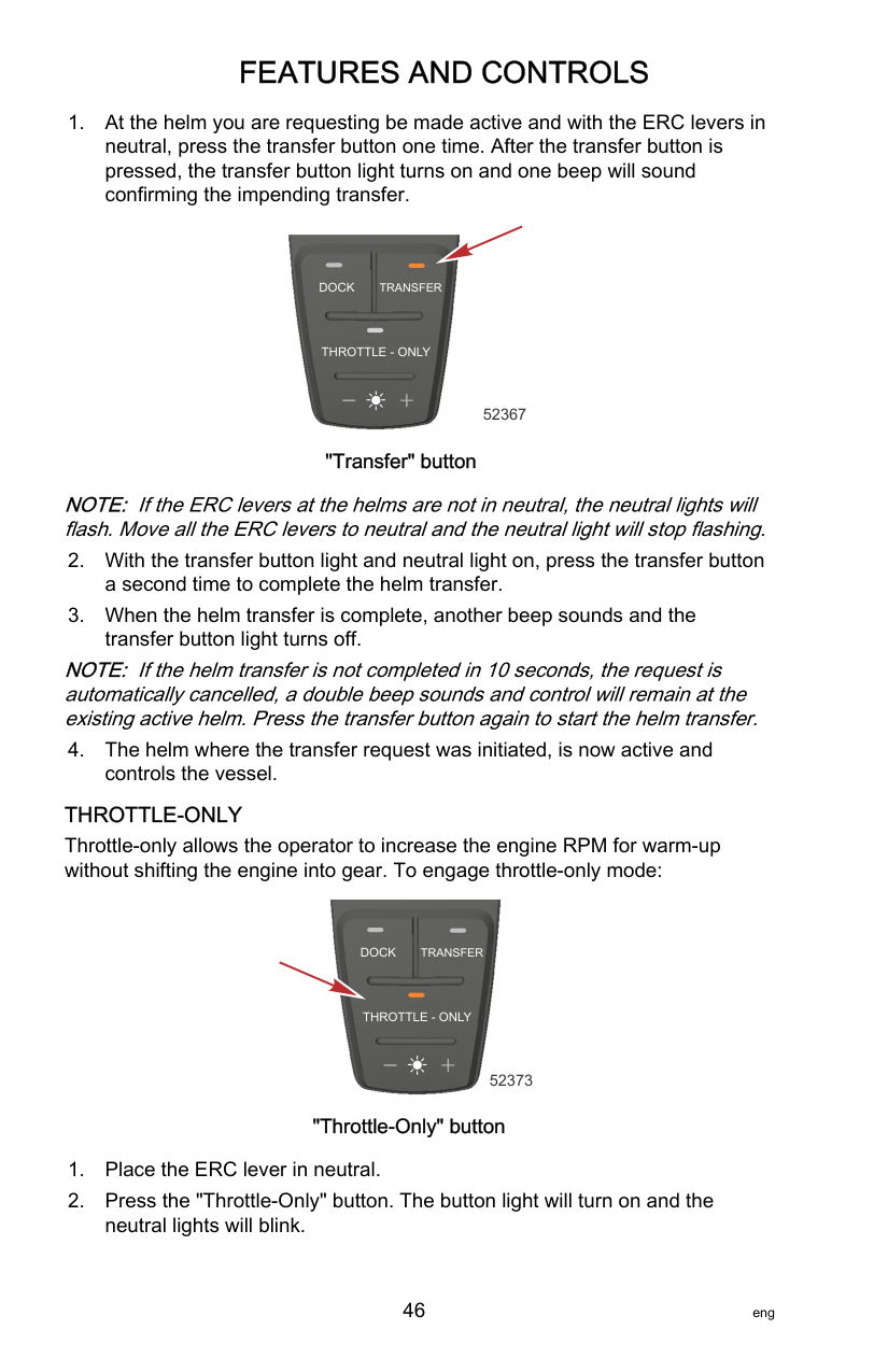
Sync Sync is an automatic engine synchronization feature that is always on unless it is turned off. Sync monitors the position of both ERC levers. When both levers are within 10% of one another, the port engine synchronizes to the starboard engine's RPM. The SmartCraft system will automatically disengage sync after 95% of throttle position range to allow each engine the ability to reach maximum available RPM. Sync cannot engage until the engines are at a minimum speed. The indicator light on the SYNC button is on when both engines are on. The light is yellow at idle and 95% of throttle and when the engines are not synchronized. The light turns red when the engines are synchronized.

51857
############################# SYNC button
The RPM display of VesselView also shows an orange icon under the RPM numbers if the engines RPMs differ more than 10% of each other, and the icon turns red when they are synchronized. To disengage sync mode:
Transfer (Boats equipped with dual helms) The TRANSFER button allows the boat operator to transfer control of the boat from the active helm to the inactive helm on boats equipped with dual helms. Refer to Helm Transfer.

51858
############################# TRANSFER button
HELM TRANSFER Some boats are designed to allow control of the vessel from more than one location. These locations are commonly referred to as helms or stations. Helm transfer is a term used to describe the method of transferring control from one helm (or station) to another helm.
||!| |---|
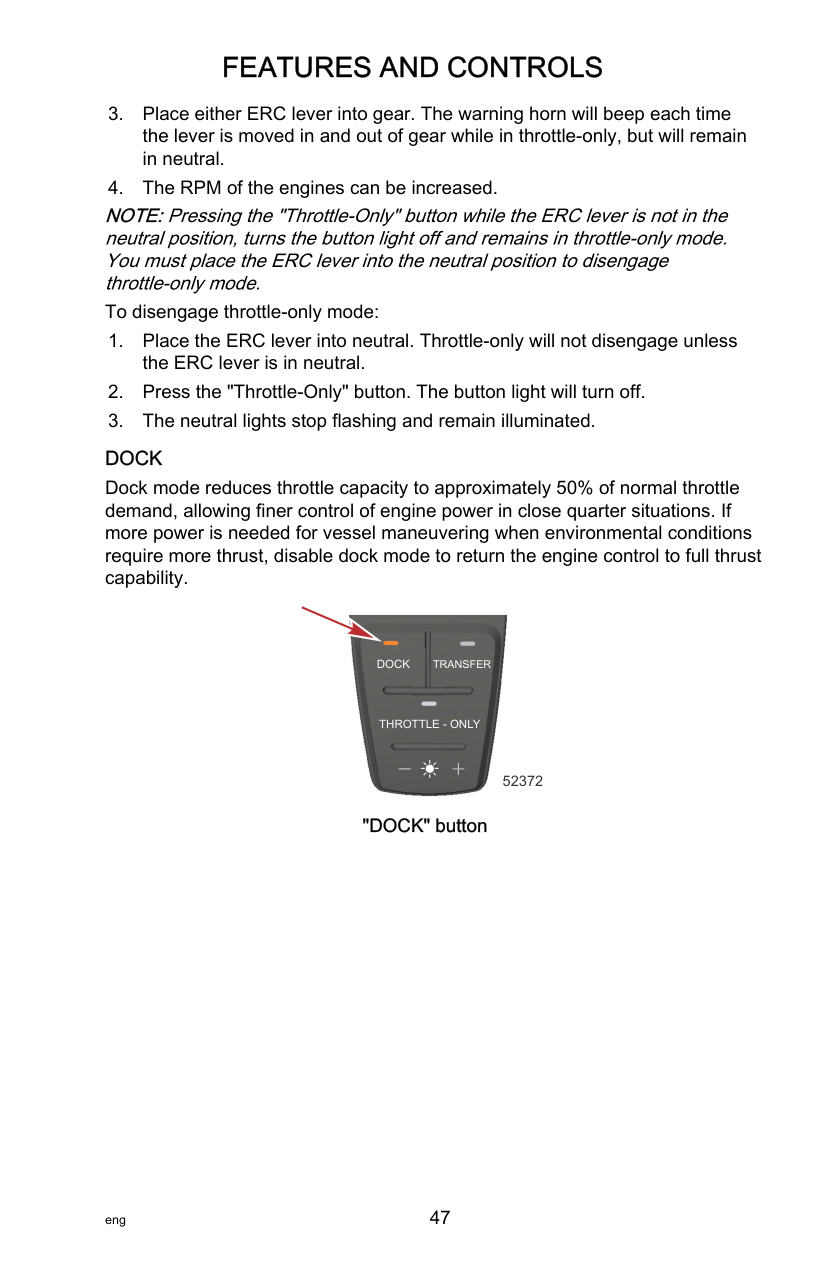
WARNING| |---| |Avoid serious injury or death from loss of boat control. The boat operator should never leave the active station while engine is in gear. Helm transfer should only be attempted while both stations are manned. One‑person helm transfer should only be performed while engine is in neutral.|
The helm transfer function allows the boat operator to select which helm is in control of the vessel. Before a transfer can be initiated the ERC levers at the active helm and at the helm intended for the transfer must be in the neutral position. NOTE:If you attempt to transfer helm control when the ERC levers are not in neutral, a beep will sound and the helm transfer will not succeed until the levers at the helms are moved to neutral and transfer is requested again.
Some fault codes may appear on VesselView if other control or navigation functions are attempted after the helm transfer procedure is started. To remove the fault codes it may be necessary to cycle the key switch OFF and ON, and then restart the helm transfer procedure. Ensure that other control and navigation inputs are performed after helm transfer is complete to avoid setting fault codes.
|NOTICE| |---| |The ERC levers must be in neutral to perform a helm transfer. While in neutral your vessel could drift and collide with objects nearby resulting in damage. Keep an adequate look out while performing the helm transfer.|
To avoid damage, use extra care when attempting a helm transfer while the vessel is close to docks, piers, or other fixed items or when near other vessels.
REQUESTING HELM TRANSFER NOTE:Any movement of the ERC levers after pressing the TRANSFER button terminates the helm transfer request. A single beep sounds and the transfer button light turns off signaling the end of the transfer request. To request the transfer of vessel control from one helm to another:

51858
TRANSFER button
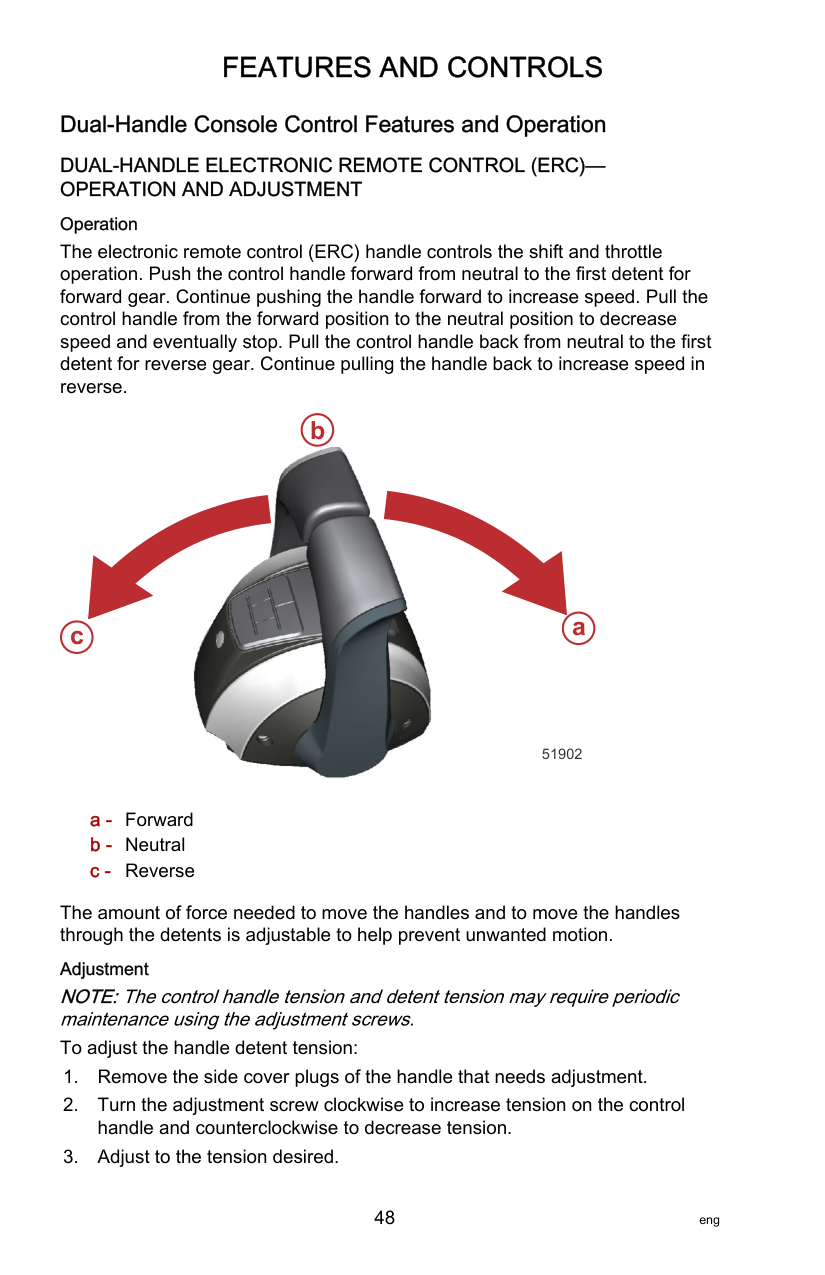
NOTE:If the ERC levers at the helms are not in neutral, the neutral lights will flash. Move all the ERC levers to neutral and the neutral light will stop flashing.
NOTE:If the helm transfer is not completed in 10 seconds, the request is automatically cancelled and a double beep sounds. Control will remain at the existing active helm. Press the TRANSFER button again to restart helm transfer.
######################## Shadow Mode Control with CAN Trackpad Features and Operation
TRIPLE ENGINE THROTTLE AND SHIFT OPERATION Movement of the handles on the remote control allows the boat operator to control the engine throttle speed and gear shift positions of all three engines. The throttle and shift function is dependant on what engines are running. Refer to the following table.
|Port Engine|Center Engine|Starboard Engine|Control Handle Function| |---|---|---|---| |Running|Running|Running|Port engine throttle and shift = controlled by port control handle| |Running|Running|Running|Starboard engine throttle and shift = controlled by starboard control handle| |Running|Running|Running|Center engine throttle = average of port and starboard engines| |Running|Running|Running|Center engine shift = neutral unless both engines are in the same gear| |Running|Running|Off|Port and center engine throttle and shift = controlled by port control handle| |Off|Running|Running|Starboard and center engine throttle and shift = controlled by starboard control handle| |Running|Off|Running|Port engine throttle and shift = controlled by port control handle| |Running|Off|Running|Starboard engine throttle and shift = controlled by starboard control handle| |Running|Off|Off|Port engine throttle and shift = controlled by port control handle| |Off|Off|Running|Starboard engine throttle and shift = controlled by starboard control handle|
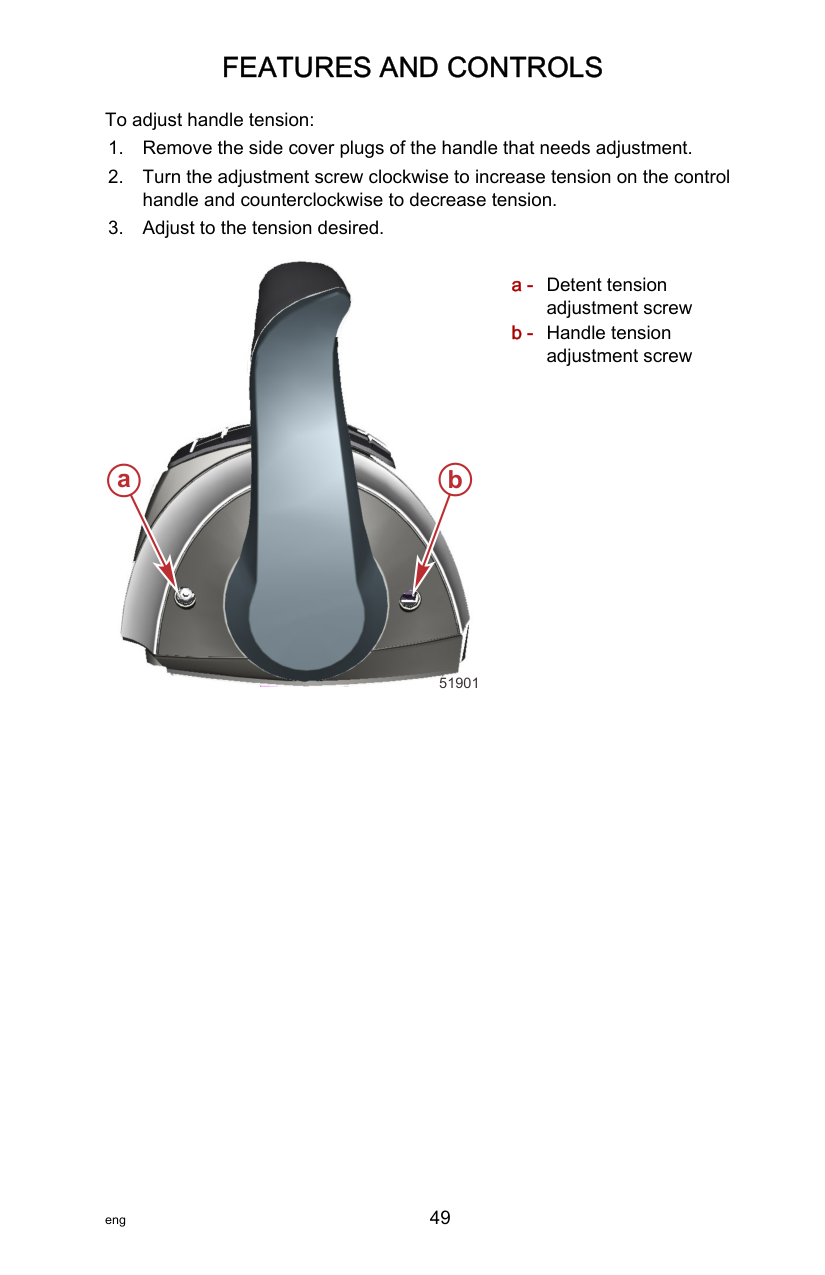
|Off (ignition key switch turned on)|Running|Off (ignition key switch turned on)|Center engine throttle and shift = neutral/idle unless both control handles are in the same gear|
Turning off one of the outer engines while underway will cause the center engine to go into forced neutral/idle. Operation to the center engine can be restored by moving the control handle of the functioning outer engine back into neutral position and then engaging. The center engine speed and gear shift will then be controlled by the functioning outer engine. Turning off the center engine while underway will have no effect on the operation of the outer engines. If a failure should occur while underway which causes one of the outer engines into forced neutral/idle condition, the center engine will also be forced to neutral/idle. Operation to the center engine can be restored by moving the control handle of the functioning outer engine back into neutral and then engaging.
######################## Hot Foot REQUIREMENTS FOR OPERATION OF A HOT FOOT
Engine speed is controlled from idle to WOT by either the foot throttle or the panel mount control handle. Hot foot throttle operation requires the DTS system be set up with a switch that can turn the hot foot throttle control off or on. This will allow the boat operator to select the throttle operation through the electronic remote control assembly or through the hot foot control assembly.
########################### DTS HOT FOOT OPERATION DTS Hot Foot
DTS hot foot operation use is unique and is generally used on boats that can reach significant speeds. The use of a hot foot allows the operator to keep both hands on the steering wheel at all speeds, which allows the operator a greater control of the boat.
a
b
c
d
3786
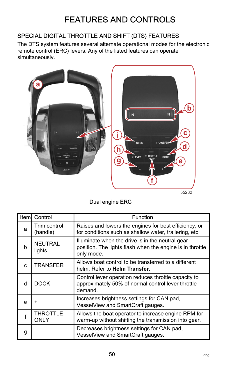
Hand and Foot Control Operation with Hand Throttle On/Off Switch
e. Throttle control at the panel mount remote control handle. NOTE:If the transfer fails, a double horn beep will sound.
############################# 4. To return throttle control to the foot throttle:
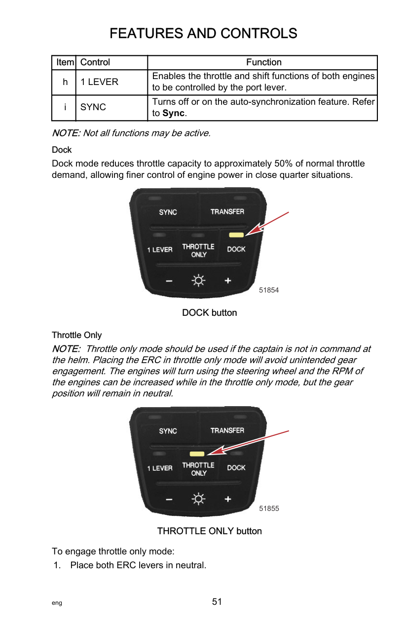
NOTE:If the transfer fails, a double horn beep will sound.
b
################## a c

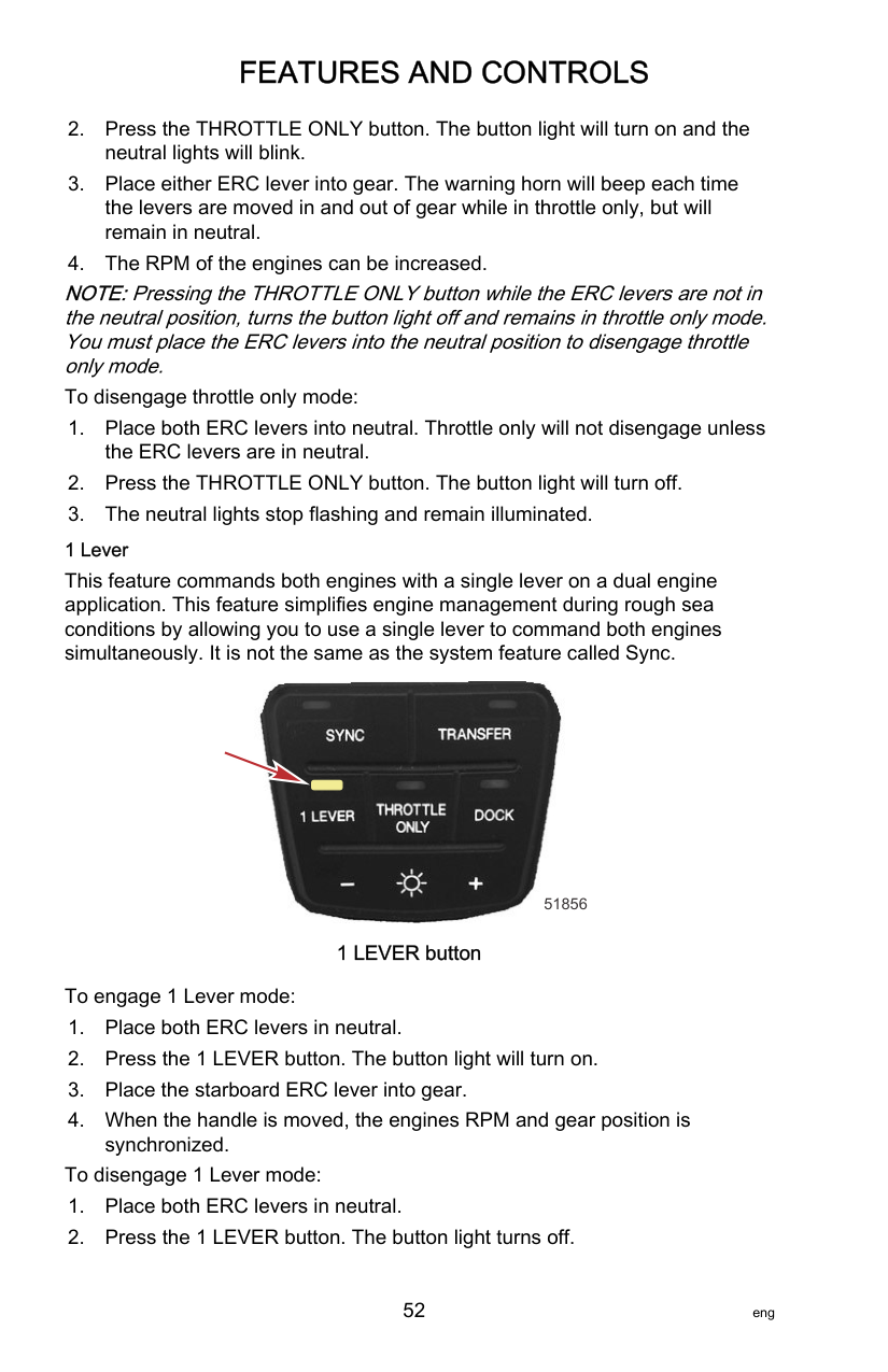
gh
21084
######################## Zero Effort Controls
Zero Effort controls allow the operator to control the shifting and throttle with separate control handles. Zero Effort controls are available in single, and multiengine applications including shadow mode operation.

58266
Warning System WARNING HORN SIGNALS When the key switch is turned to the ON position, the horn will turn on for a moment as a test to indicate the horn is working. There are two types of warning horns to alert the operator of an active problem within the engine’s operating system.
It is important to note that in either of the above scenarios, the horn will only sound one time. If you key the engine off and restart it, the horn will sound again, one time, if the fault is still present. For visual display of the specific engine functions and additional engine data, refer to SmartCraft Product information, following. A few of the noncritical conditions indicated by the intermittent short beeps for six seconds can be corrected by the operator. These operator correctable conditions are as follows:
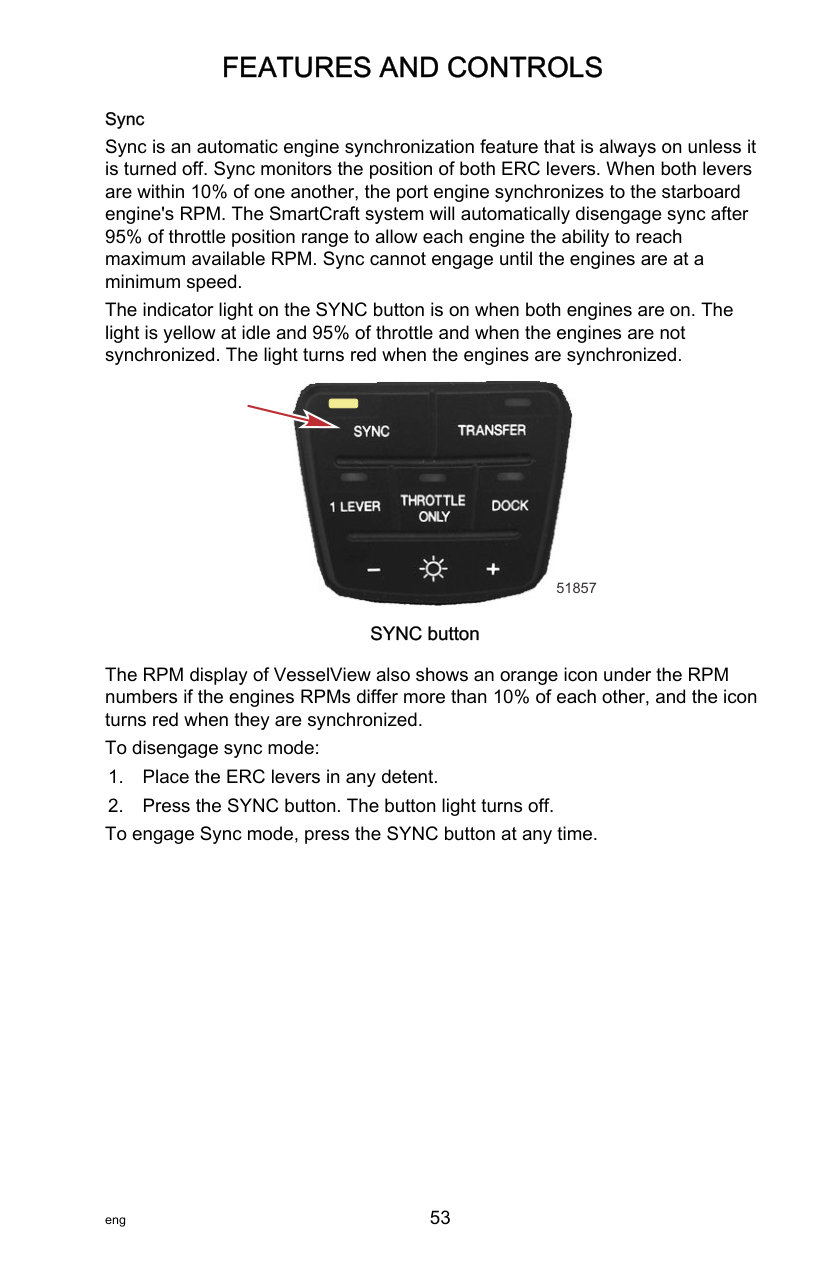
ENGINE GUARDIAN SYSTEM The Engine Guardian system monitors the critical sensors on the engine for any early indications of problems. Engine Guardian is functional whenever your engine is operating, so you never have to be concerned about whether or not you are protected. The system will respond to a problem by sounding the warning horn for six seconds and/or reducing engine power in order to provide engine protection. If Engine Guardian has been activated, reduce the engine speed. The problem will need to be identified and corrected. The system must be reset before the engine will operate at higher speeds. Moving the throttle lever back to the idle position will reset the Engine Guardian system. If the Engine Guardian system has determined the reset has not corrected the problem, Engine Guardian will remain activated, limiting the throttle. The problem must be identified and corrected before Engine Guardian will allow the engine to reach a normal operating RPM.
OVERSPEED REV LIMIT The overspeed rev limit is set at an RPM greater than the operating range. In the event that the engine is operated at an RPM greater than or equal to the overspeed limit, the PCM does not allow the engine to maintain the power requested by the operator. Refer to General Information ‑ Specification to determine this engine’s RPM limit. Upon reaching the beginning of the overspeed rev limit, Engine Guardian will cut fuel to one bank of cylinders. If the operator does not reduce engine speed, Engine Guardian will cut the fuel to all cylinders until the engine speed has dropped below the rev limit. There is no audible warning while Engine Guardian overspeed limit is active.
SMARTCRAFT PRODUCT A Mercury SmartCraft System instrument package can be purchased for this outboard. A few of the functions the instrument package will display are engine RPM, coolant temperature, oil pressure, water pressure, battery voltage, fuel consumption, and engine operating hours. The SmartCraft instrument package will also aid in Engine Guardian diagnostics. The SmartCraft instrument package will display critical engine alarm data and potential problems.
EXHAUST GAS OVER TEMPERATURE When the Engine Guardian system detects the exhaust gas temperature is high (fault code 2124‑20), the warning horn will beep and the engine RPM will be limited. SmartCraft gauges which have the ability display text, will alert the operator with a short text, long text, and the action which the operator should follow. This Guardian warning and engine power reduction can possibly be corrected by inspecting the gear housing water inlet for blockage and the exhaust water strainer for blockage. Refer to Maintenance ‑ Exhaust Water Strainer Inspection.
|SmartCraft Displayed Text|SmartCraft Displayed Text| |---|---| |Short text|Critical ‑ Overtemp| |Long text|Engine exhaust manifold is overheating| |Action|Stop engine and check for plugged exhaust water strainer. If condition persists return to port immediately. Service engine before next use.|
######################## Power Trim and Tilt
The outboard has a trim/tilt control called power trim. This enables the operator to easily adjust the position of the outboard by pressing the trim switch. Moving the outboard in closer to the boat transom is called trimming in or down. Moving the outboard further away from the boat transom is called trimming out or up. The term trim generally refers to the adjustment of the outboard within the first 20° range of travel. This is the range used while operating the boat on plane. The term tilt is generally used when referring to adjusting the outboard further up out of the water. The outboard can be tilted up past the trim range for shallow water operation or loading the boat onto a trailer. With the engine turned off and ignition switch turned on, the outboard can be tilted out of the water.
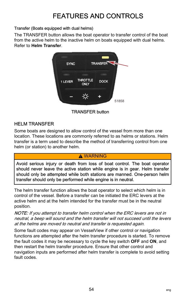
• If the engine is below 2000 RPM and is in the trailer range, advancing the throttle will allow the engine to achieve a maximum RPM of 4250. Engine operation in this capacity (above the normal 2000 limit) should only be used for loading or unloading the boat onto or off the trailer. It should not be used during normal boat operation.
NOTE:Exceeding 4250 RPMs the engine PCM will begin Engine Guardian protection.


a UP
DN
b
c
63388
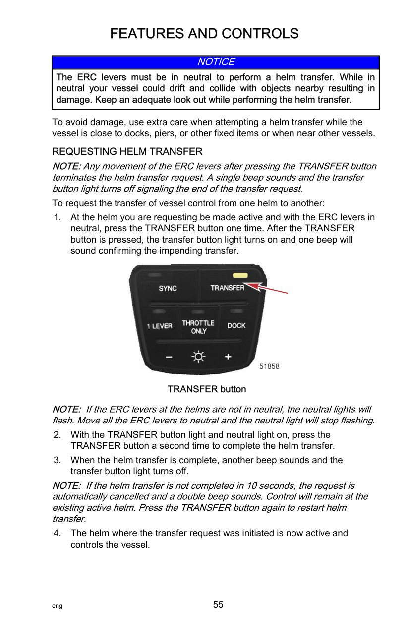
POWER TRIM OPERATION With most boats, operating around the middle of the trim range will give satisfactory results. However, to take full advantage of the trimming capability there may be times when you choose to trim your outboard all the way in or out. Along with an improvement in some performance aspects comes a greater responsibility for the operator, and this is being aware of some potential control hazards. The most significant control hazard is a pull or torque that can be felt on the steering wheel or tiller handle. This steering torque results from the outboard being trimmed so the propeller shaft is not parallel to the water surface.
||!| |---|
WARNING| |---| |Trimming the outboard beyond a neutral steering condition may result in a pull on the steering wheel or tiller handle and loss of boat control. Maintain control of the boat if trimming beyond a neutral steering condition.|
Consider the following lists carefully.
• Lower the bow
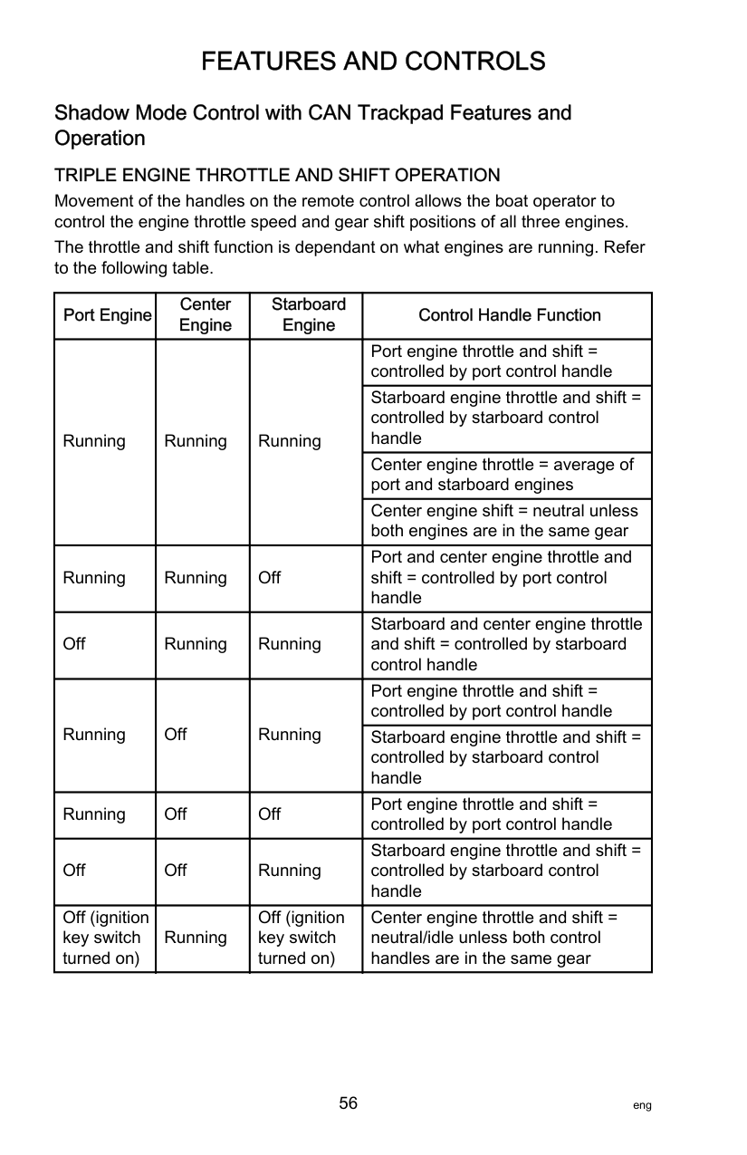
########################### TILTING OPERATION
To tilt outboard, shut off the engine and press the trim/tilt switch or auxiliary tilt switch to the up position. The outboard will tilt up until the switch is released or it reaches its maximum tilt position.

a
b
47705
a - Tilt support lever b - Knob
MANUAL TILTING If the outboard cannot be tilted using the power trim/tilt switch, the outboard can be manually tilted.
NOTE:The manual tilt release valve must be tightened before operating the outboard to prevent the outboard from tilting up during reverse operation.
Turn out the manual tilt release valve three turns counterclockwise. This allows manual tilting of the outboard. Tilt the outboard to the desired position and tighten the manual tilt release valve.

64233
AUXILIARY TILT SWITCH This switch can be used to tilt the outboard up or down using the power trim system.

########## a
47704
a - Auxiliary tilt switch
OPERATING IN SHALLOW WATER When operating your boat in shallow water, you can tilt the outboard beyond the maximum trim range to prevent hitting bottom.
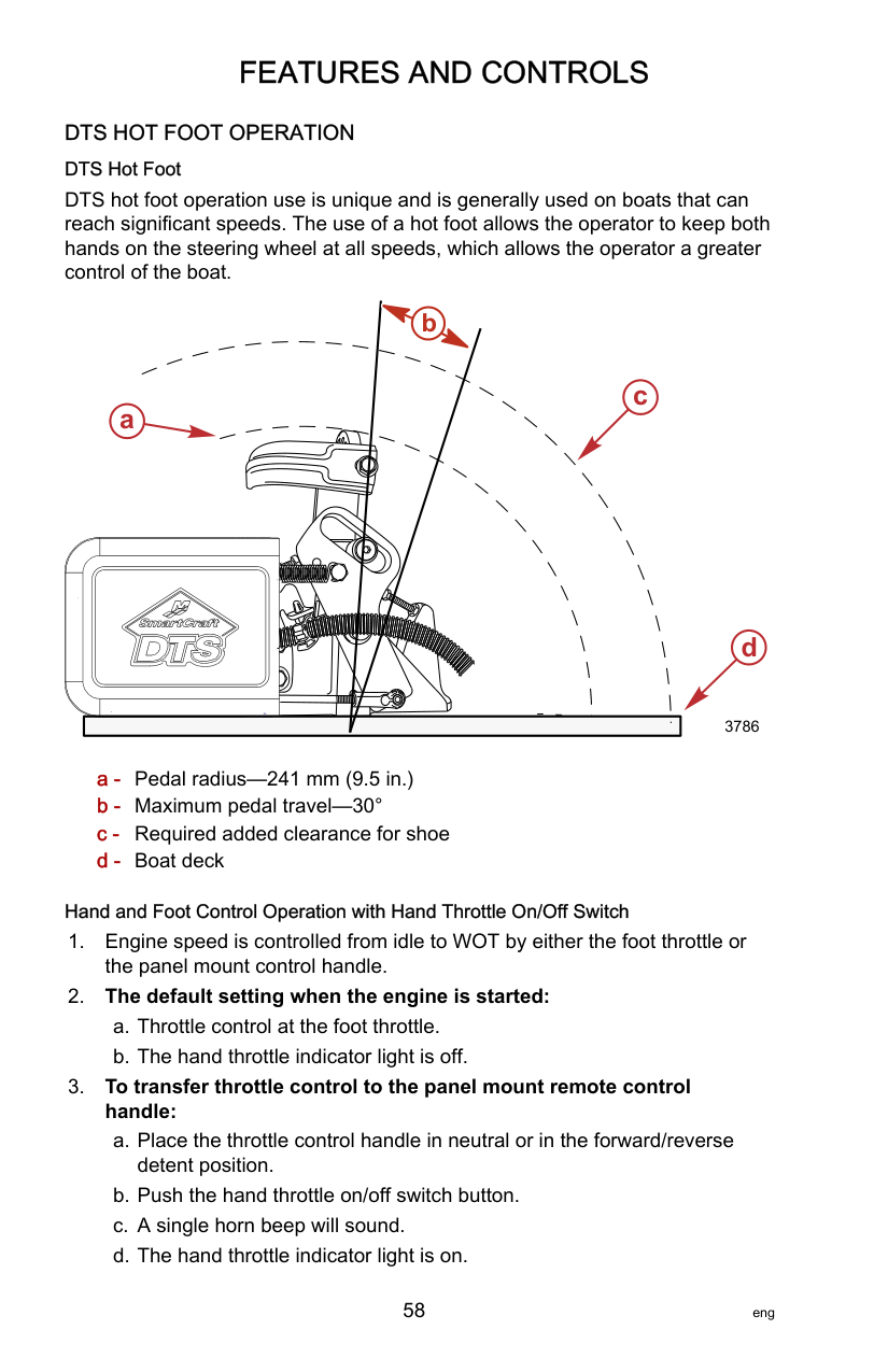
############################ NOTE:Exceeding 4250 RPMs the engine PCM will begin Engine Guardian protection.
######################## Important Daily Inspection Before Each Use
Any outboard mounted on the boat must have the mounting hardware inspected and checked to ensure that the hardware has not become loose. A decal on the transom bracket reminds the owner to check the fasteners securing the outboard to the transom before each use.

51985 Decal on the transom bracket
######################## Prestarting Check List
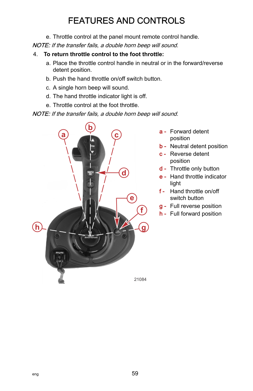
######################## Operating in Freezing Temperatures
If there is a chance of ice forming on the water, the outboard should be removed and drained completely of water. If ice should form at any level inside the outboard driveshaft housing between the water pump and the powerhead, it will block cooling water flow to the engine which may cause possible damage.
If the boat cannot be removed from the water during freezing temperatures, the outboard should be tilted up so the trailing edge of the antiventilation plate is protruding slightly above the water surface—refer to the following graphic illustration. At this tilt angle, the engine’s water pump and cooling water passages are best protected from freezing up with ice.

0

64809
Operating in Saltwater or Polluted Water We recommend that you flush the internal water passages of your outboard with fresh water after each use in salt or polluted water. This will prevent a buildup of deposits from clogging the water passages. Refer to Maintenance ‑ Flushing the Cooling System. If you keep your boat moored in the water, always tilt the outboard so the gearcase is completely out of water (except in freezing temperatures) when not in use. Wash the outboard exterior and flush out the exhaust outlet of the propeller and gearcase with fresh water after each use. Each month, spray Mercury or Quicksilver Corrosion Guard on external metal surfaces. Do not spray on corrosion control anodes as this will reduce the effectiveness of the anodes.
|Tube Ref No.|Description|Where Used|Part No.| |---|---|---|---| |120|Corrosion Guard|External metal surfaces|92-802878 55|
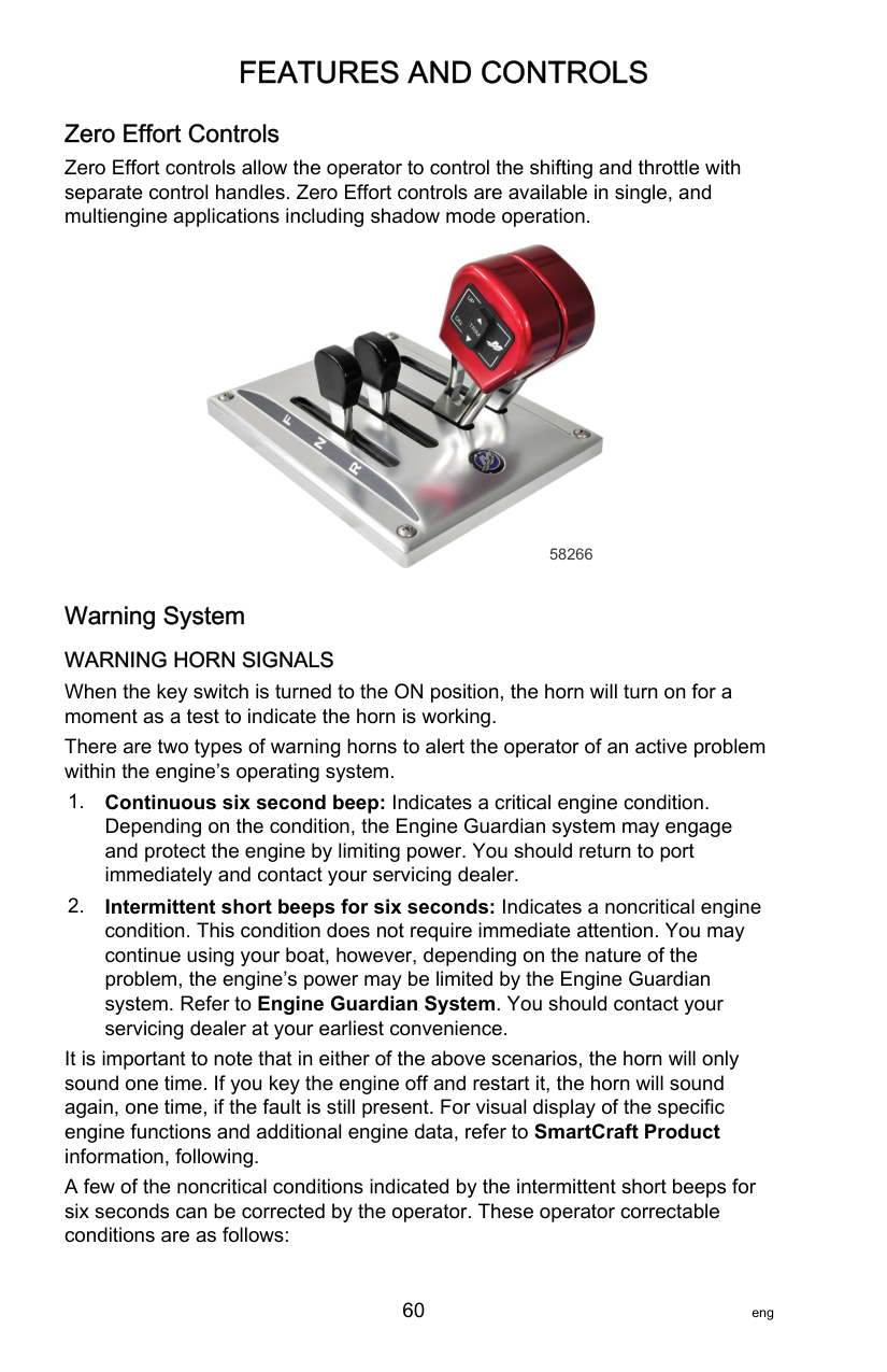
IMPORTANT: Do not rinse the cowls with water when the outboard is in a tilted position, as this could allow water to enter the air intakes on the rear of the upper cowl. Always lower the outboard to a vertical position prior to rinsing the cowls.


71770 Do not rinse cowl while outboard is tilted
######################## Operating at High Elevations
Your engine automatically compensates for high elevation changes. A different pitch propeller may help reduce some normal performance loss resulting from reduced oxygen in the air. Consult your dealer.
######################## Effects of Elevation and Weather on Performance
The following conditions lower engine performance and cannot be compensated by the engine fuel or electronic management systems:
These conditions above reduce air density to the engine, which in turn lowers the following:
EXAMPLE: An engine running at an elevation of 8,000 feet will have over a 30% power loss while a loss of engine power on a hot and humid day could be as much as 14%. These losses apply to normally aspirated and supercharged engines.
############################# Compensating for power robbing conditions:
Some boat performance can be improved by dropping to a lower pitch propeller, but engine performance will still remain lower. In some cases, a gear ratio reduction may be more beneficial. To optimize engine performance, prop the engine to allow it to operate at or near the top end of the recommended maximum RPM range at wide‑open throttle with a normal boat load. Other advantages to propeller or gear ratio changes:
######################## Setting Trim Angle while Running Engine at Idle Speed
The exhaust relief hole on the outboard can become submerged on some boats if the engine is trimmed full in while running at idle speed. This may result in exhaust restriction, rough idle, excessive smoke, and fouled spark plugs. If this condition exists, trim outboard up until exhaust relief hole is out of the water.


########### b
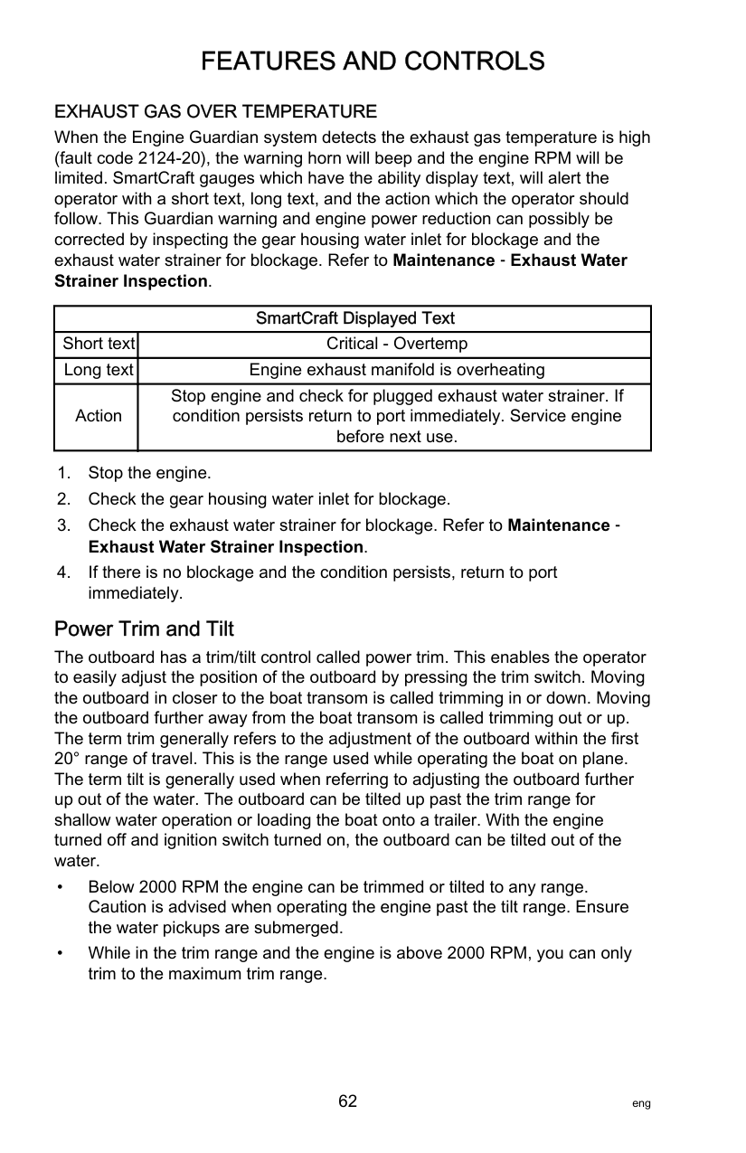
########### a
63389
a - Relief hole submerged (wrong) b - Relief hole above waterline (correct)
######################## Engine Break‑in Procedure
############################# IMPORTANT: Failure to follow the engine break‑in procedures can result in poor performance throughout the life of the engine and can cause engine damage. Always follow break‑in procedures.
######################## Fuel Supply Module Priming Procedure
The fuel supply module (FSM) is not vented to the ambient air. The air trapped in the FSM, fuel lines, and fuel rail, will be slightly compressed during the initial ignition key on with a dry or drained fuel system. Additional key on events under these conditions, will not compress the air further to finish the priming of the FSM. Excessive number of key on events may eventually damage the fuel pumps. The volume of air trapped in the FSM must be purged to prime the fuel system. This can be achieved by connecting a tool to the fuel rail Schrader valve fitting to quickly purge the system into an approved container, or by cranking the engine.
PRIMING THE FSM WITH A PURGE TOOL The use of a purge tool for priming the FSM is the preferred method, but is not always practical. The objective is to purge the air entrained in the fuel system through a purge tool connected to the fuel rail Schrader valve test port. During the key on, opening the dump valve will allow the air to be purged from the FSM and fuel rail. This method should be used on vessels when the fuel system leading to the outboard is restrictive; antisiphon valve or holds a relatively large volume of fuel because of a long fuel supply line or a vessel mounted water‑separating fuel filter is installed. If a primer bulb is installed, it can be used during the priming event to shorten the amount of time required to start the engine.
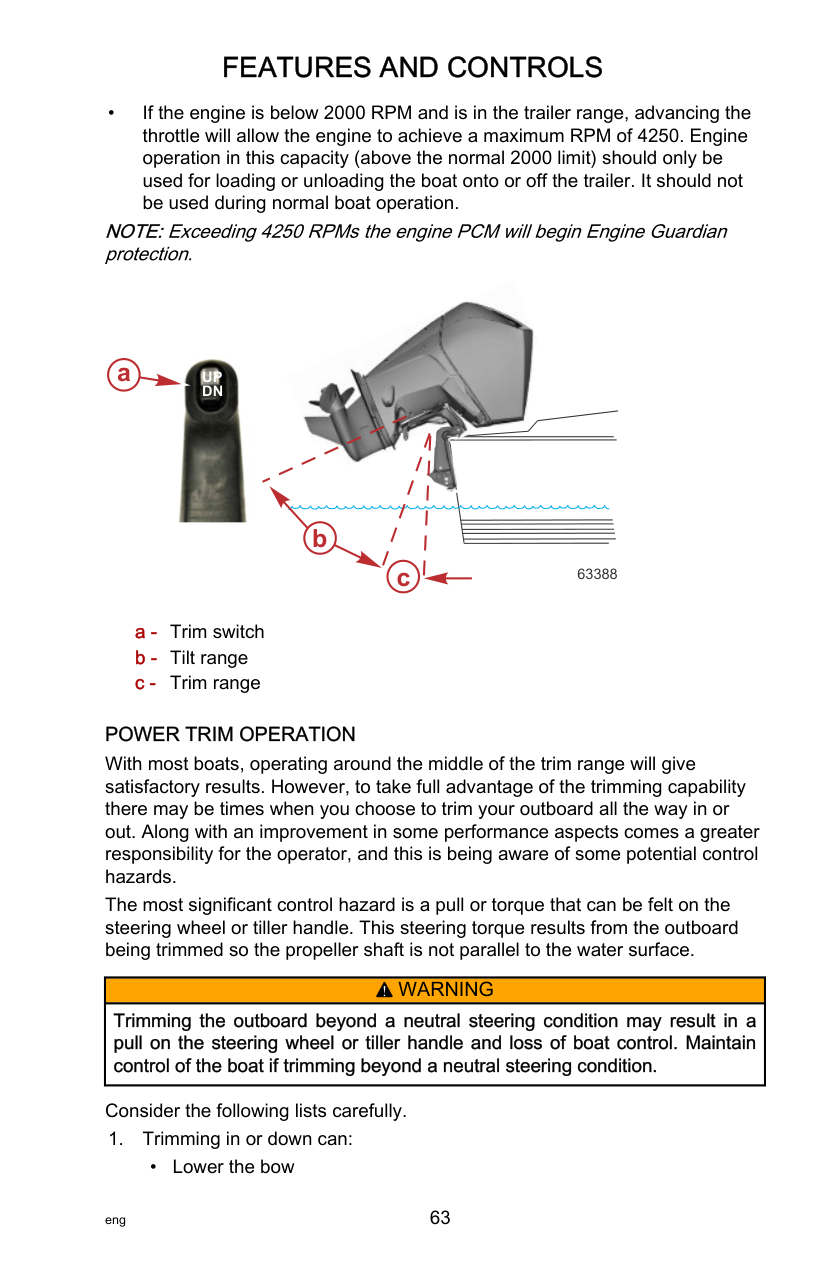
NOTE:If the outboard fuel system does not prime within 15 key ON events, check for leaks in the fuel supply line to the outboard. Repair as needed. If no leak is found, the fuel supply system to the outboard may be too restrictive. Correct the condition and try again.
PRIMING THE FSM (RAN OUT OF FUEL CONDITION) The use of a purge tool for priming the FSM is the preferred method, but is not always practical. When the vessel fuel system is void of fuel volume, it can be primed without the use of a purge tool. The objective is to purge the air entrained in the fuel system through the fuel injectors during engine cranking to allow fuel to enter the fuel module. This method can be used on vessels where the fuel inlet system to the outboard is less restrictive and holds a relatively small volume of fuel; a short fuel supply line, no water‑separating fuel filter, or water‑separating fuel filter is already primed. If a primer bulb is installed, it can be used during the priming event to shorten the amount of time required to start the engine. NOTE:In most cases, the priming procedure can be accomplished by purging the air from one fuel rail.
NOTE:When priming a drained fuel system, residual fuel may cause the engine to flare and stall which shortens the engine cranking event.
IMPORTANT: Allow the starter motor to cool for 20 to 30 seconds between full eight second crank events. Limit the number of events to a maximum of 10 full eight second cranking events.
######################## Starting the Engine
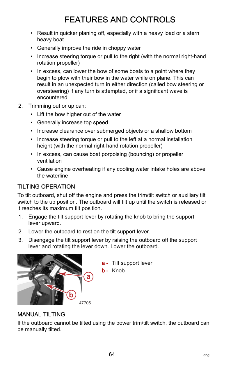
Before starting, read the Prestarting Check List, special operating instructions, Engine Break‑in Procedure, Gear Shifting in this section, and the remote control features and operation in the Features and Controls section.
|NOTICE| |---| |Without sufficient cooling water, the engine, the water pump, and other components will overheat and suffer damage. Provide a sufficient supply of water to the water inlets during operation.|
############################# 1. Check the engine oil level. Refer to Fuel and Oil ‑ Checking and AddingEngine Oil.

b
a
c
63305
a - Service access door b - Oil fill cap c - Dipstick
############################## 2. Verify the cooling water intake is submerged.

63390
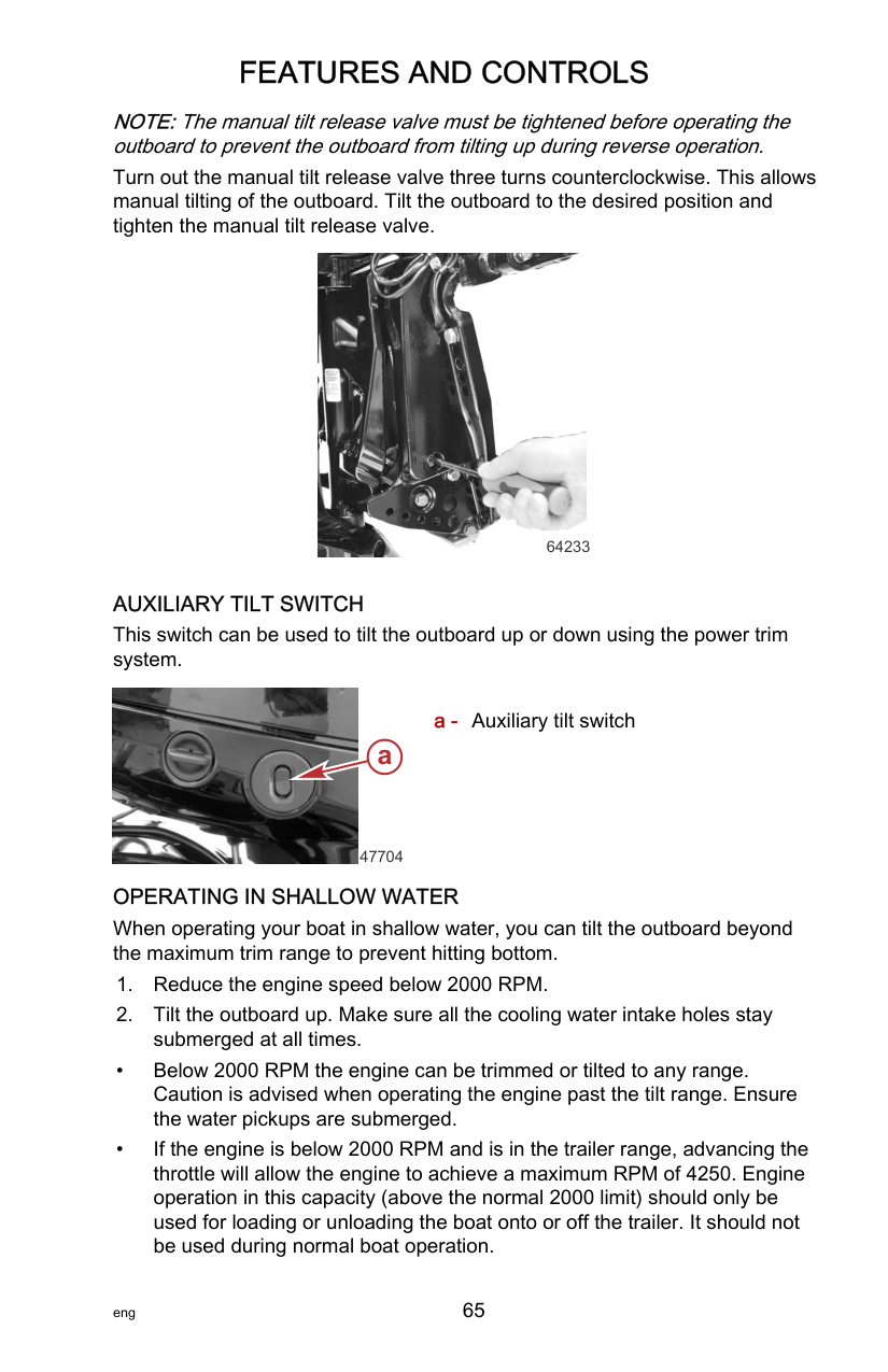
a - Fuel cap b - Vent screw c - Tab lock
19791
b
a

c
46290
################ b


################ a
################ c
51902
a - Forward b - Neutral c - Reverse
NOTE:For initial start of a new engine or for an engine that ran out of fuel, refer toFuel Supply Module Priming Procedure.
R T
O
F
F
A
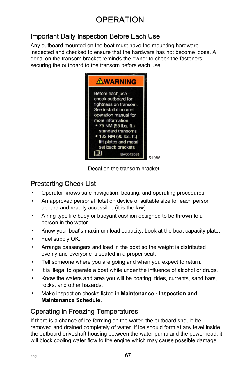
C
C
O
N
S
T
A R T
O
F
F
A
C
C
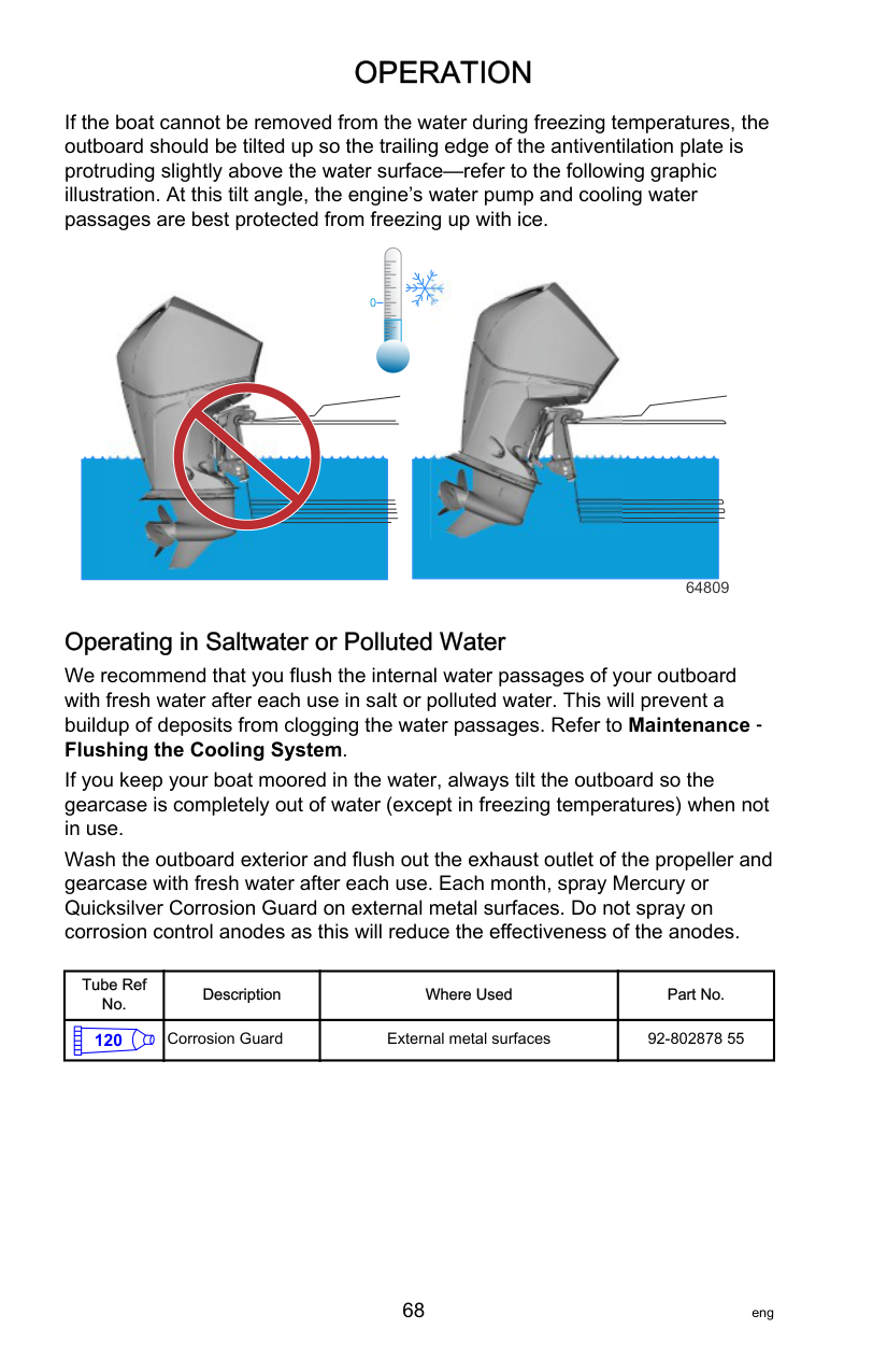
O
N
3485
IMPORTANT: If no water is coming out of the water pump indicator hole, stop the engine and check the cooling water intake for obstruction. No obstruction may indicate a water pump failure or blockage in the cooling system. These conditions will cause the engine to overheat. Have the outboard checked by your dealer. Operating the engine while overheated will cause engine damage.
Gear Shifting IMPORTANT: Observe the following:
DTS PANEL MOUNT REMOTE CONTROL IMPORTANT: Never shift the outboard into gear unless the engine speed is at idle.
3427
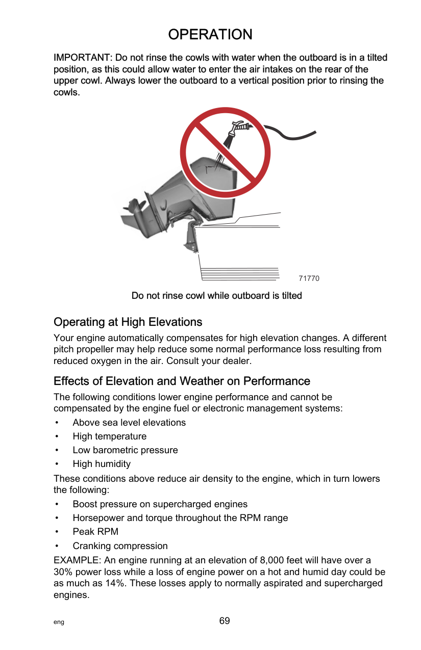
F
N
R
3428
########################### DTS CONSOLE MOUNT REMOTE CONTROL IMPORTANT: Never shift the outboard into gear unless the engine speed is at idle.
a - Forward b - Neutral c - Reverse
b
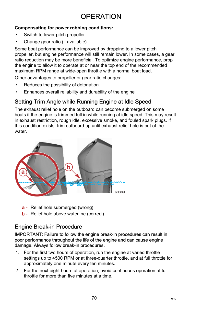

a
c
51902
b a
c

58267
a - Shift levers in neutral position b - Trim switch c - Throttle levers at the idle position
######################## Stopping the Engine
############################# IMPORTANT: Turning key to the START position while the engine is running will result in engine shut down, while leaving the DTS system active. This will allow the use of the power trim/tilt from the remote control handle.
Reduce engine speed and shift outboard to neutral position. Turn ignition key to OFF position.
C
A
C
O
F
N
F
O
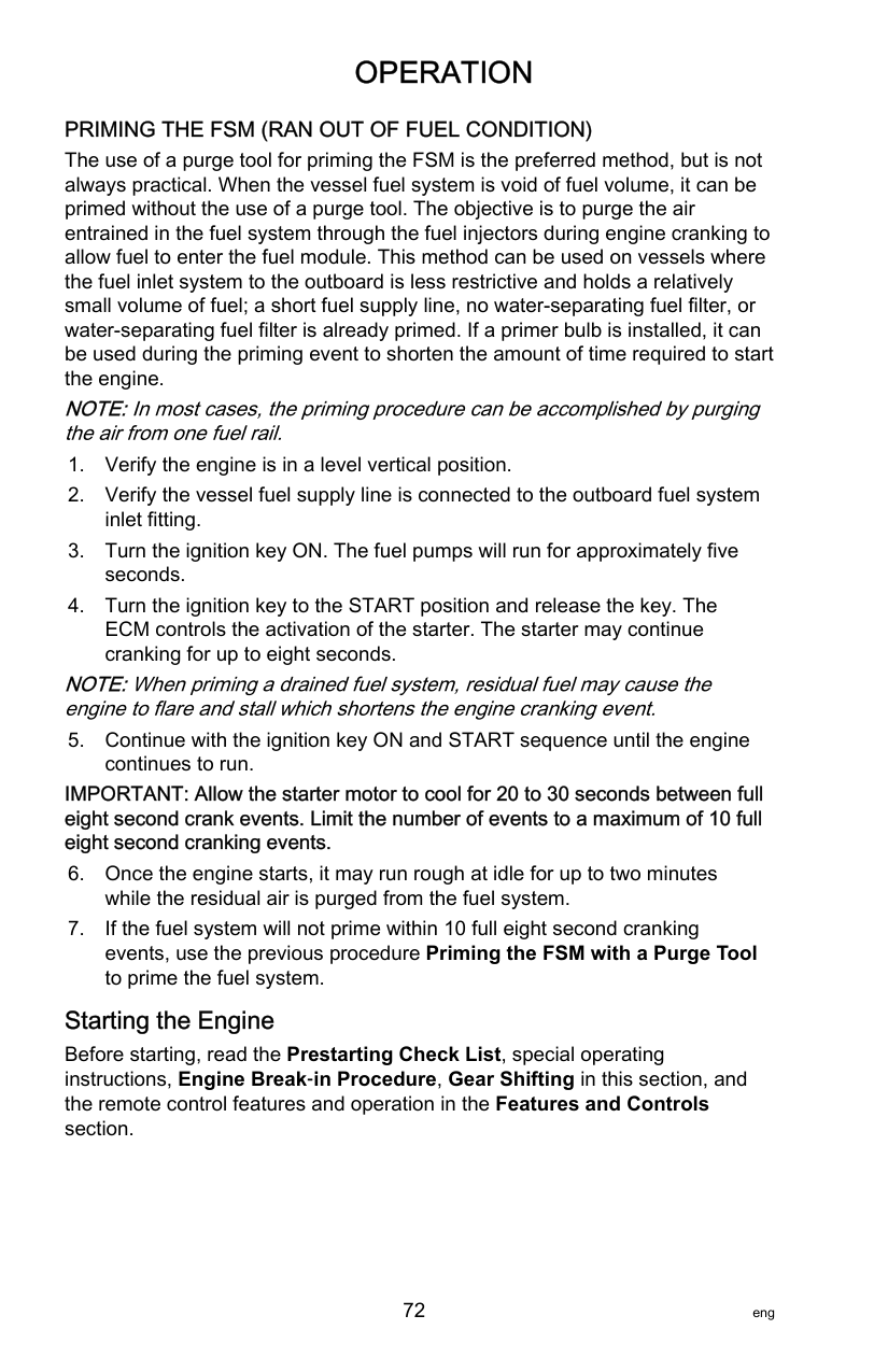
C
A
C
O
F
F
N
R T
O
R T
3482
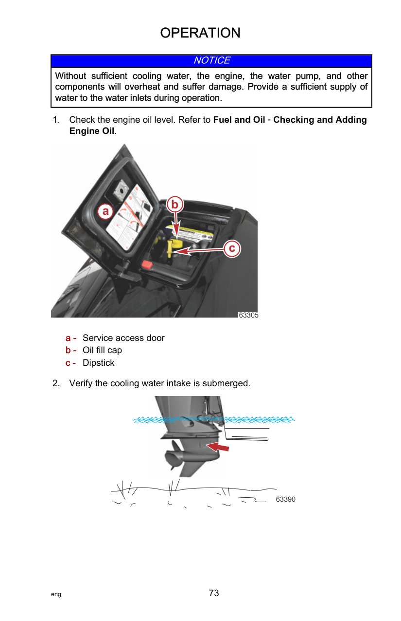
Proper Outboard Tilt Positioning During Periods of Non‑Use With the engine turned off, tilt the outboard up to a point where the trailing edge of the anti‑ventilation plate is angled higher than the leading edge. With the engine off, the outboard tilt angle will:


################# a
71383b
######################## Cleaning Care Recommendations OUTBOARD CARE
To keep your outboard in the best operating condition, it is important that your outboard receive the periodic inspections and maintenance listed in the Inspection and Maintenance Schedule. We urge you to keep it maintained properly to ensure the safety of you and your passengers, and retain its dependability. Record maintenance performed in the Maintenance Log at the back of this book. Save all maintenance work orders and receipts. Selecting Replacement Parts For Your Outboard
We recommend using original Mercury Precision or Quicksilver replacement parts and Genuine Lubricants.
DO NOT USE CAUSTIC CLEANING CHEMICALS IMPORTANT: Do not use caustic cleaning chemicals on the outboard power package. Some cleaning products contain strong caustic agents such as hull cleaners with hydrochloric acid. These cleaners can degrade some of the components they come in contact with including critical steering fasteners.
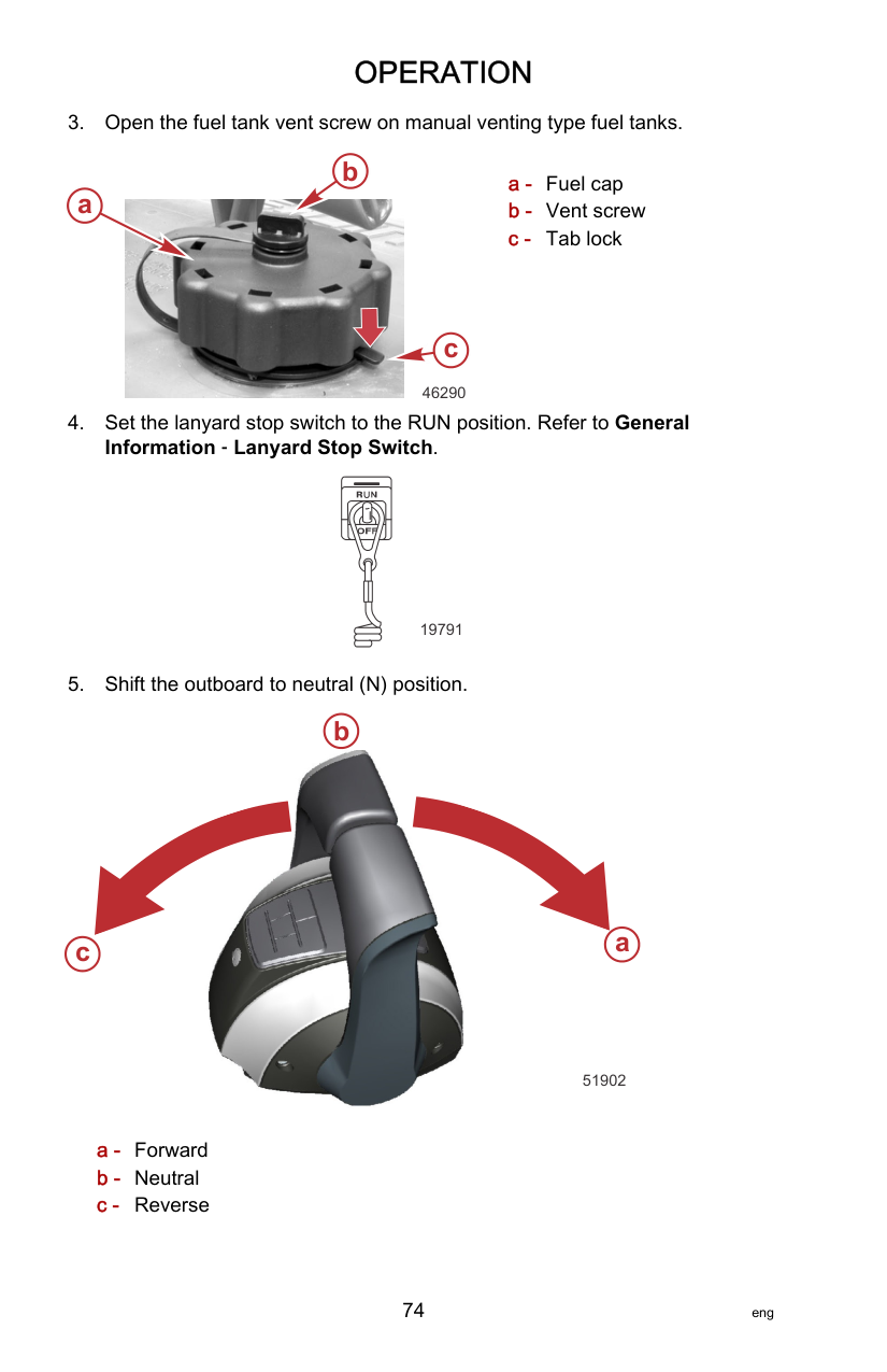
Damage to steering fasteners may not be obvious during visual inspection and this damage may lead to catastrophic failure. Some caustic cleaning chemicals may cause or accelerate corrosion. Exercise caution when using cleaning chemicals around the engine and follow the recommendations on the packaging of the cleaning product.
CLEANING GAUGES IMPORTANT: Never use high‑pressure water to clean gauges. Routine cleaning of the gauges is recommended to prevent a buildup of salt and other environmental debris. Crystalized salt can scratch the gauge display lens when using a dry or damp cloth. Ensure that the cloth has a sufficient amount of fresh water to dissolve and remove salt or mineral deposits. Do not apply aggressive pressure on the display lens while cleaning. When water marks cannot be removed with a damp cloth, mix a 50/50 solution of warm water and isopropyl alcohol to clean the display lens. Do not use acetone, mineral spirits, turpentine type solvents, or ammonia based cleaning products. The use of strong solvents or detergents may damage the coating, the plastics, or the rubber keys on the gauges. If the gauge has a sun cover available, it is recommended that the cover be installed when the unit is not in use to prevent UV damage to the plastic bezels and rubber keys.
########################### CLEANING REMOTE CONTROLS IMPORTANT: Never use high‑pressure water to clean remote controls.
Routine cleaning of the remote control external surfaces is recommended to prevent a buildup of salt and other environmental debris. Use a cloth towel which has a sufficient amount of fresh water to dissolve and remove salt or mineral deposits. When water marks cannot be removed with a damp cloth, mix a 50/50 solution of warm water and isopropyl alcohol to clean the remote control. Do not use acetone, mineral spirits, turpentine type solvents, or ammonia based cleaning products. The use of strong solvents or detergents may damage the coating, the plastics, or the rubber components on the remote control.
CLEANING CARE FOR TOP AND BOTTOM COWLS IMPORTANT: Dry wiping (wiping the plastic surface when it is dry) will result in minor surface scratches. Always wet the surface before cleaning. Do not use detergents containing hydrochloric acid. Follow the cleaning and waxing procedure. Cleaning and Waxing Procedure
IMPORTANT: Do not rinse the cowls with water when the outboard is in a tilted position, as this could allow water to enter the air intakes on the rear of the upper cowl. Always lower the outboard to a vertical position prior to rinsing the cowls.


71770 Do not rinse cowl while outboard is tilted
CLEANING CARE FOR THE POWERHEAD (SALTWATER USE) If the outboard is operated in saltwater, remove the top cowl and flywheel cover. Inspect the powerhead and powerhead components for salt buildup. Wash off any salt buildup from the powerhead and powerhead components with fresh water. Keep water spray out of the air filter/intake and alternator. After washing, allow the powerhead and components to dry. Apply Quicksilver or Mercury Corrosion Guard spray on the external metal surfaces of the powerhead and powerhead components. Do not allow the Corrosion Guard spray to come in contact with the alternator drive belt or belt pulleys.
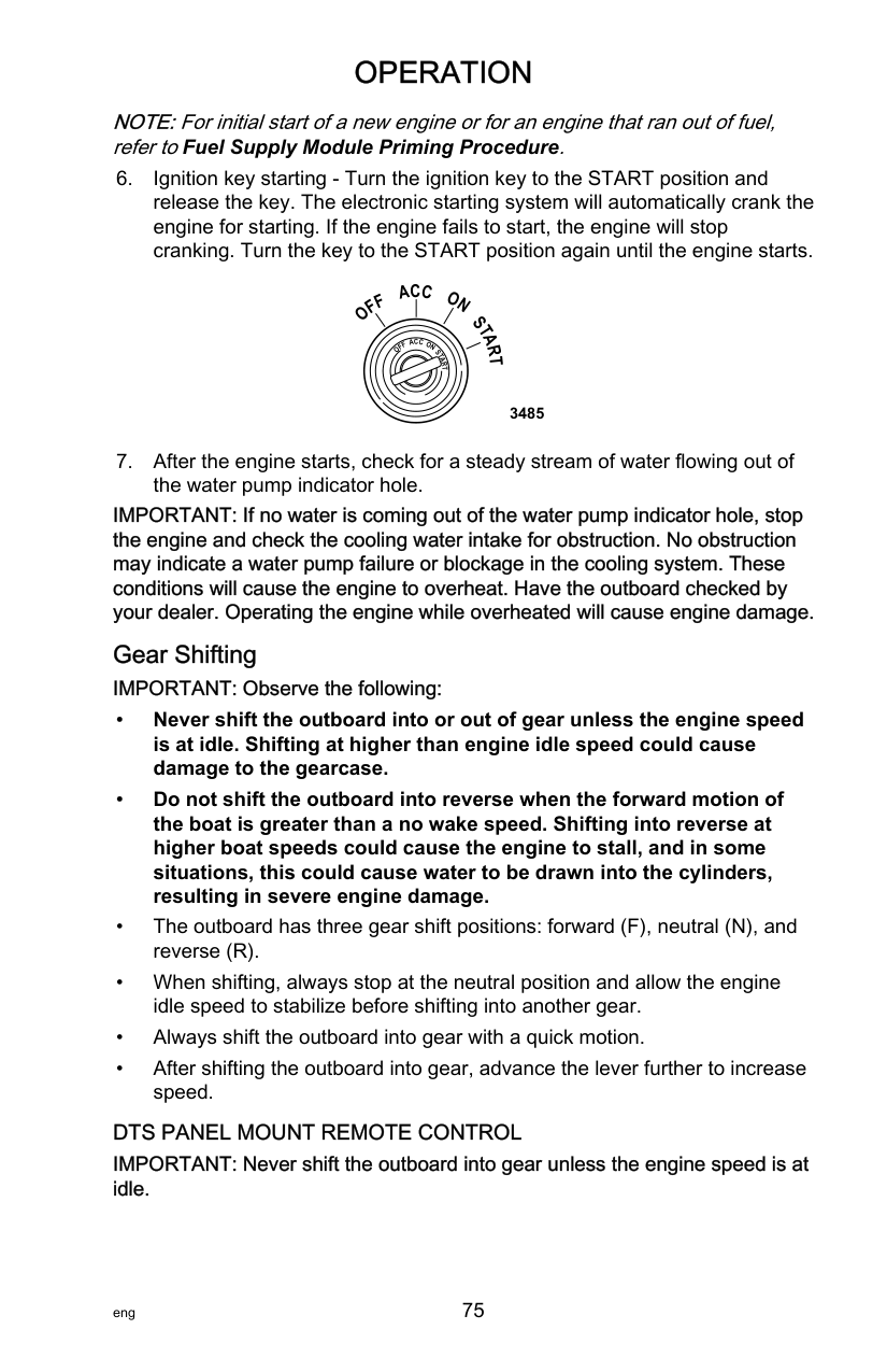
IMPORTANT: Do not allow lubricant or Corrosion Guard spray to come in contact with the alternator drive belt or the belt pulleys. The alternator drive belt could slip and be damaged if it becomes coated with any lubricant or Corrosion Guard spray.
|Tube Ref No.|Description|Where Used|Part No.| |---|---|---|---| |120|Corrosion Guard|External metal surfaces of the powerhead and powerhead components.|92-802878 55|
EPA Emissions Regulations All new outboards manufactured by Mercury Marine are certified to the United States Environmental Protection Agency, as conforming to the requirements of the regulations for the control of air pollution from new outboard motors. This certification is contingent on certain adjustments set to factory standards. For this reason, the factory procedure for servicing the product must be strictly followed and, wherever practicable, returned to the original intent of the design. Maintenance, replacement, or repair of the emission control devices and systems may be performed by any marine spark ignition (SI) engine repair establishment or individual.
EMISSION CERTIFICATION LABEL An emission certification label, showing emission levels and engine specifications directly related to emissions, is placed on the engine at the time of manufacture.
| | | |EMISSION CONTROL INFORMATION|EMISSION CONTROL INFORMATION| |---|---|---|---|---| |THIS ENGINE CONFORMS TO EMISSION REGULATIONS FOR SPARK IGNITION MARINE ENGINES
CALIFORNIA AND U.S. EPA|THIS ENGINE CONFORMS TO EMISSION REGULATIONS FOR SPARK IGNITION MARINE ENGINES
CALIFORNIA AND U.S. EPA|THIS ENGINE CONFORMS TO EMISSION REGULATIONS FOR SPARK IGNITION MARINE ENGINES
CALIFORNIA AND U.S. EPA|THIS ENGINE CONFORMS TO EMISSION REGULATIONS FOR SPARK IGNITION MARINE ENGINES
CALIFORNIA AND U.S. EPA|THIS ENGINE CONFORMS TO EMISSION REGULATIONS FOR SPARK IGNITION MARINE ENGINES
CALIFORNIA AND U.S. EPA| |REFER TO OWNERS MANUAL FOR REQUIRED MAINTENANCE, SPECIFICATIONS, AND ADJUSTMENTS|REFER TO OWNERS MANUAL FOR REQUIRED MAINTENANCE, SPECIFICATIONS, AND ADJUSTMENTS|REFER TO OWNERS MANUAL FOR REQUIRED MAINTENANCE, SPECIFICATIONS, AND ADJUSTMENTS|REFER TO OWNERS MANUAL FOR REQUIRED MAINTENANCE, SPECIFICATIONS, AND ADJUSTMENTS|REFER TO OWNERS MANUAL FOR REQUIRED MAINTENANCE, SPECIFICATIONS, AND ADJUSTMENTS| |IDLE SPEED (in gear):|IDLE SPEED (in gear):|IDLE SPEED (in gear):|IDLE SPEED (in gear):|FAMILY:| |hp|hp|L|L|HC+NOx:FEL: g/kWh| |kw|kw|kw|kw|CO FEL: g/kWh| | |SPARK PLUG: GAP:|SPARK PLUG: GAP:|SPARK PLUG: GAP:|SPARK PLUG: GAP:| |LOW PERM/HIGH PERM:|LOW PERM/HIGH PERM:|LOW PERM/HIGH PERM:|LOW PERM/HIGH PERM:|LOW PERM/HIGH PERM:|
a f
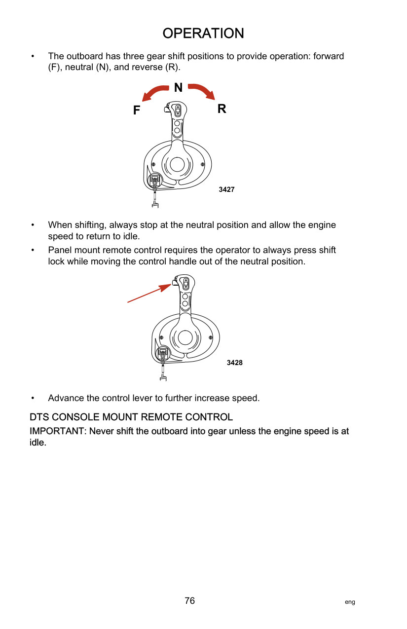
b
c
d
e
43210
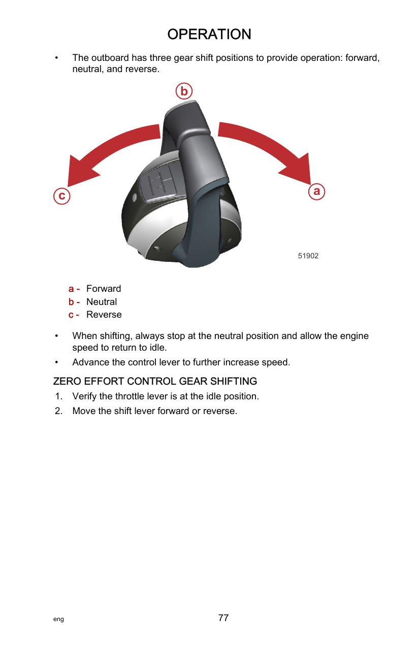
OWNER RESPONSIBILITY The owner/operator is required to have routine engine maintenance performed to maintain emission levels within prescribed certification standards.
The owner/operator is not to modify the engine in any manner that would alter the horsepower or allow emission levels to exceed their predetermined factory specifications.
######################## Inspection and Maintenance Schedule BEFORE EACH USE
|Description|Nm|lb‑in.|lb‑ft| |---|---|---|---| |Outboard mounting locknuts and bolts ‑ standard boat transom|75|–|55.3| |Outboard mounting locknuts and bolts ‑ metal lift plates and setback brackets|122|–|90|
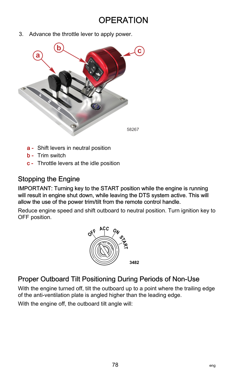
########################### EVERY 100 HOURS OF USE OR ONCE YEARLY, WHICHEVER OCCURS FIRST
|Description|Nm|lb‑in.|lb‑ft| |---|---|---|---| |Outboard mounting locknuts and bolts ‑ standard boat transom|75|–|55.3| |Outboard mounting locknuts and bolts ‑ metal lift plates and setback brackets|122|–|90|
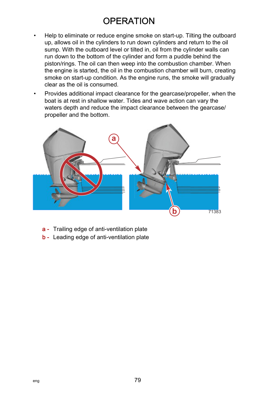
|Tube Ref No.|Description|Where Used|Part No.| |---|---|---|---| |81|Anti-Seize Compound|Spark plug threads|92-898101389|
|Tube Ref No.|Description|Where Used|Part No.| |---|---|---|---| | |Quickleen Engine & Fuel System Cleaner|Fuel tank|8M0047931|
########################### EVERY 300 HOURS OF USE OR THREE YEARS
MAINTENANCE SCHEDULE DECAL ICONS A maintenance schedule decal is located on the engine to remind the owner or operator when the power package important maintenance items require attention. The following table shows the icons and a general description of the scheduled maintenance items.
|Icon|Definition|Icon|Definition| |---|---|---|---| |58249|Replace|58250|Inspect| |58251|Engine oil and filter|58252|Gearcase lubricant| |58253|Spark plugs|58254|Thermostat| |58255|Low‑pressure fuel filter|58256|Anodes|
|Icon|Definition|Icon|Definition| |---|---|---|---| |58257|Accessory drive belt|58258|Water pump impeller|
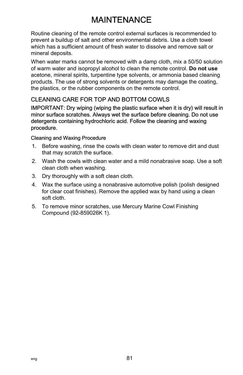
########################### V6 FOURSTROKE MODELS MAINTENANCE SCHEDULE DECAL
64026
########################### SEAPRO V6 MODELS MAINTENANCE SCHEDULE DECAL
64042
########################### V8 FOURSTROKE MODELS MAINTENANCE SCHEDULE DECAL
64043
########################### V8 PRO XS MODELS MAINTENANCE SCHEDULE DECAL
SEAPRO V8 MODELS MAINTENANCE SCHEDULE DECAL
########################### 250R AND 300R MODELS MAINTENANCE SCHEDULE DECAL
65585
Flushing the Cooling System Flush the internal water passages of the outboard with fresh water after each use in salt, polluted, or muddy water. This will help prevent a buildup of deposits from clogging the internal water passages. NOTE:The outboard can be tilted or in the vertical operating position during flushing.
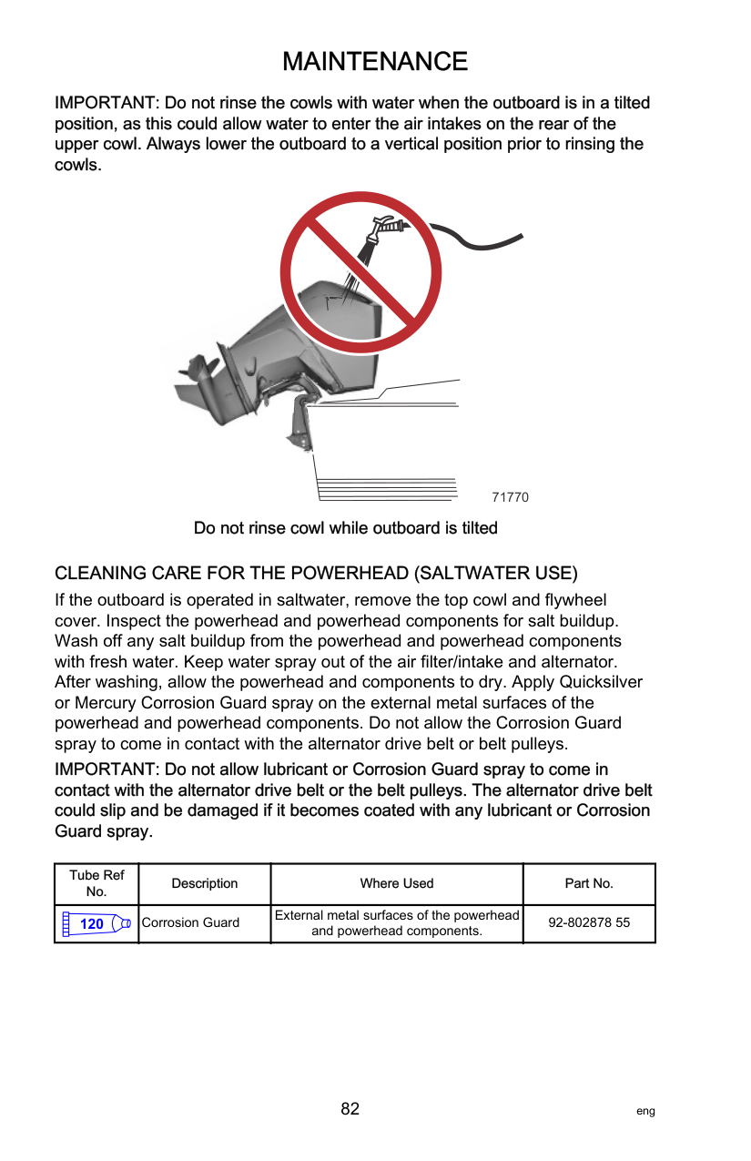

64241
Top Cowl Removal and Installation NOTE:It is recommended to remove and install the cowl while standing inside the boat. REMOVAL

64230 Push here to unlock
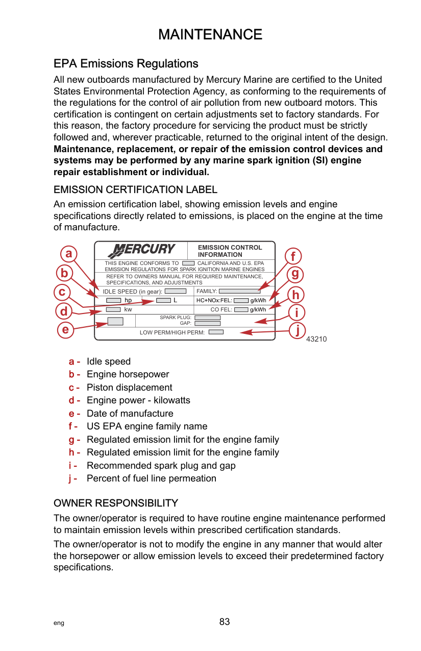

a
b
c
63306

63308 Handle locked in the lift position
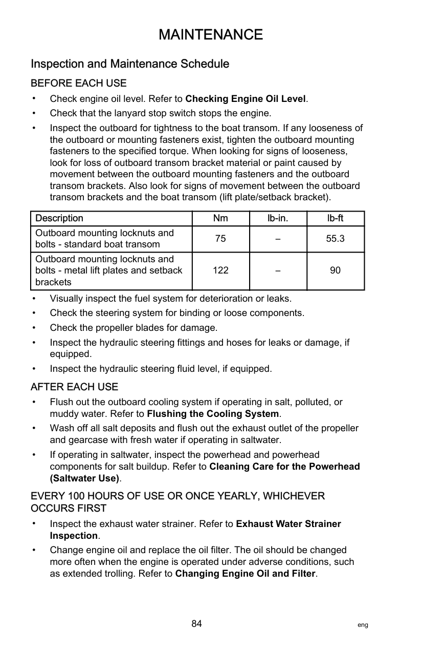
NOTE:It may be necessary to slightly lift the larger gap side of the cowl to correctly position the alignment guides.
######################## Battery Inspection
The battery should be inspected at periodic intervals to ensure proper engine starting capability.
############################# IMPORTANT: Read the safety and maintenance instructions which accompany your battery.
######################## Battery Cables and Clean Power Harness
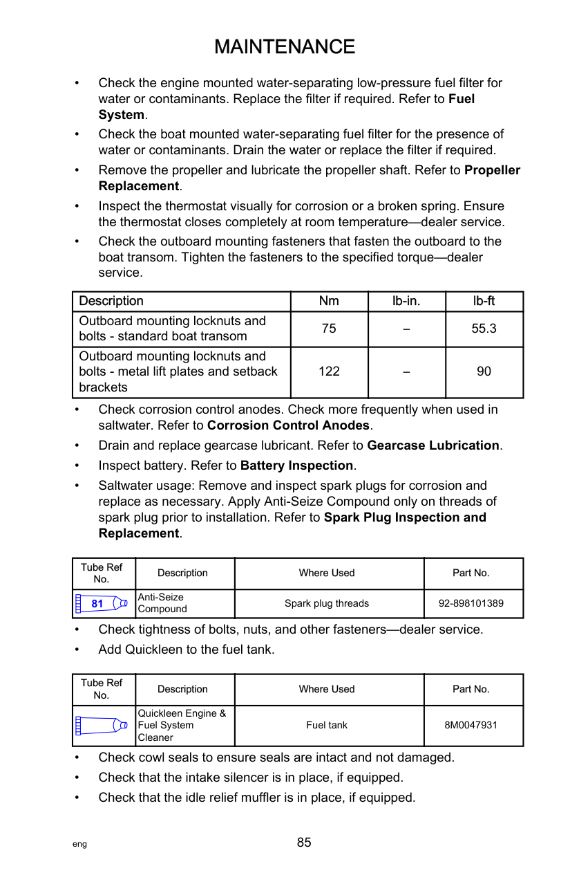
The battery cable connections should be checked often for corrosion or loose retaining hardware. Maintaining this electrical connection helps ensure the engine operation and accessories functionality remains trouble‑free. The engine starting battery cables and the clean power harness wires must be secured to the engine starting battery with nuts. Wing nuts are not acceptable. The clean power harness must be secured to one of the battery cables with a cable tie or other type of secure fastener.
a
b
| | | |---|---|
c
| | | | |---|---|---| | | | |
d
| | | |
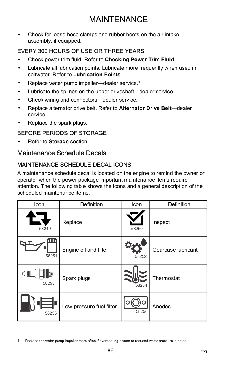
|---|---|---| | | | |
26984
If the clean power harness fuse is open, try to locate and correct the cause of the overload. If the cause is not found, the fuse may open again. Remove the clean power fuse and look at the silver band inside the fuse. If the band is broken (open), replace the fuse with the same rating (5 amp) and type fuse.
IMPORTANT: An ATC fuse has the fuse element enclosed or sealed inside the plastic housing. This type of fuse must be used for marine applications. Marine applications are exposed to environments that may have the potential to accumulate explosive vapors. ATO fuses have exposed elements and should never be used in marine applications.

b a
| | | | |---|---|---| | | | | | | | |
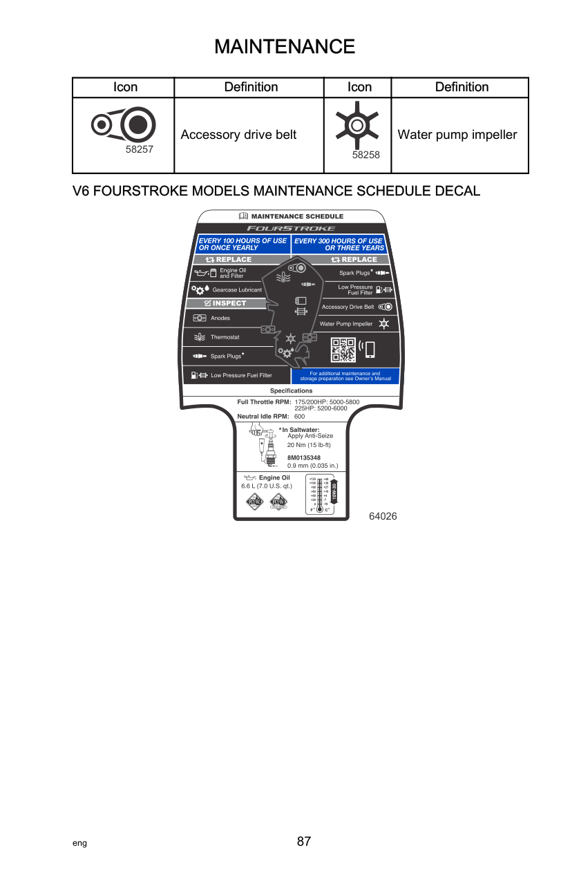
| | | | |---|---|---| | | | | | | | |
######### d e
c
64518
########################### BATTERY CONNECTIONS IMPORTANT: The engine electrical system is negative (–) ground.
When connecting the engine battery, hex nuts must be used to secure the battery leads to the battery posts. Tighten the hex nuts to the specified torque.
|Description|Nm|lb‑in.|lb‑ft|
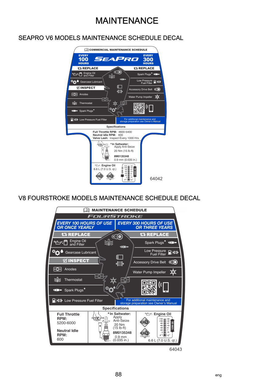
|---|---|---|---| |Battery hex nuts|13.5|120|–|
ORDER OF CONNECTION Connect the battery cables in the following order:
######################## Fuel System
||!| |---|
WARNING| |---| |Fuel is flammable and explosive. Ensure that the key switch is OFF and the lanyard is positioned so that the engine cannot start. Do not smoke or allow sources of spark or open flame in the area while servicing. Keep the work area well ventilated and avoid prolonged exposure to vapors. Always check for leaks before attempting to start the engine, and wipe up any spilled fuel immediately.|
IMPORTANT: Use an approved container to collect and store fuel. Wipe up spilled fuel immediately. Material used to contain spilled fuel must be disposed of in an approved receptacle. Before servicing any part of the fuel system:
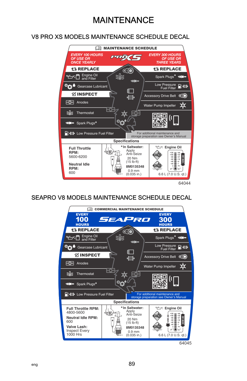
FUEL LINE INSPECTION Visually inspect the fuel line for cracks, swelling, leaks, hardness, or other signs of deterioration or damage. If any of these conditions are found, the fuel line must be replaced.
LOW-PRESSURE FUEL FILTER The low‑pressure fuel filter can be serviced as a general maintenance item when the water‑in‑fuel alarm is activated.
||!| |---|
WARNING| |---| |Fuel is flammable and explosive. Ensure that the key switch is OFF and the lanyard is positioned so that the engine cannot start. Do not smoke or allow sources of spark or open flame in the area while servicing. Keep the work area well ventilated and avoid prolonged exposure to vapors. Always check for leaks before attempting to start the engine, and wipe up any spilled fuel immediately.|
Removal IMPORTANT: Use an approved container to collect and store fuel. Wipe up spilled fuel immediately. Material used to contain spilled fuel must be disposed of in an approved container.
NOTE:If there is a boat mounted water‑separating fuel filter with a water‑in‑fuel sensor installed, the sensor harness would be connected to the boat mounted filter.
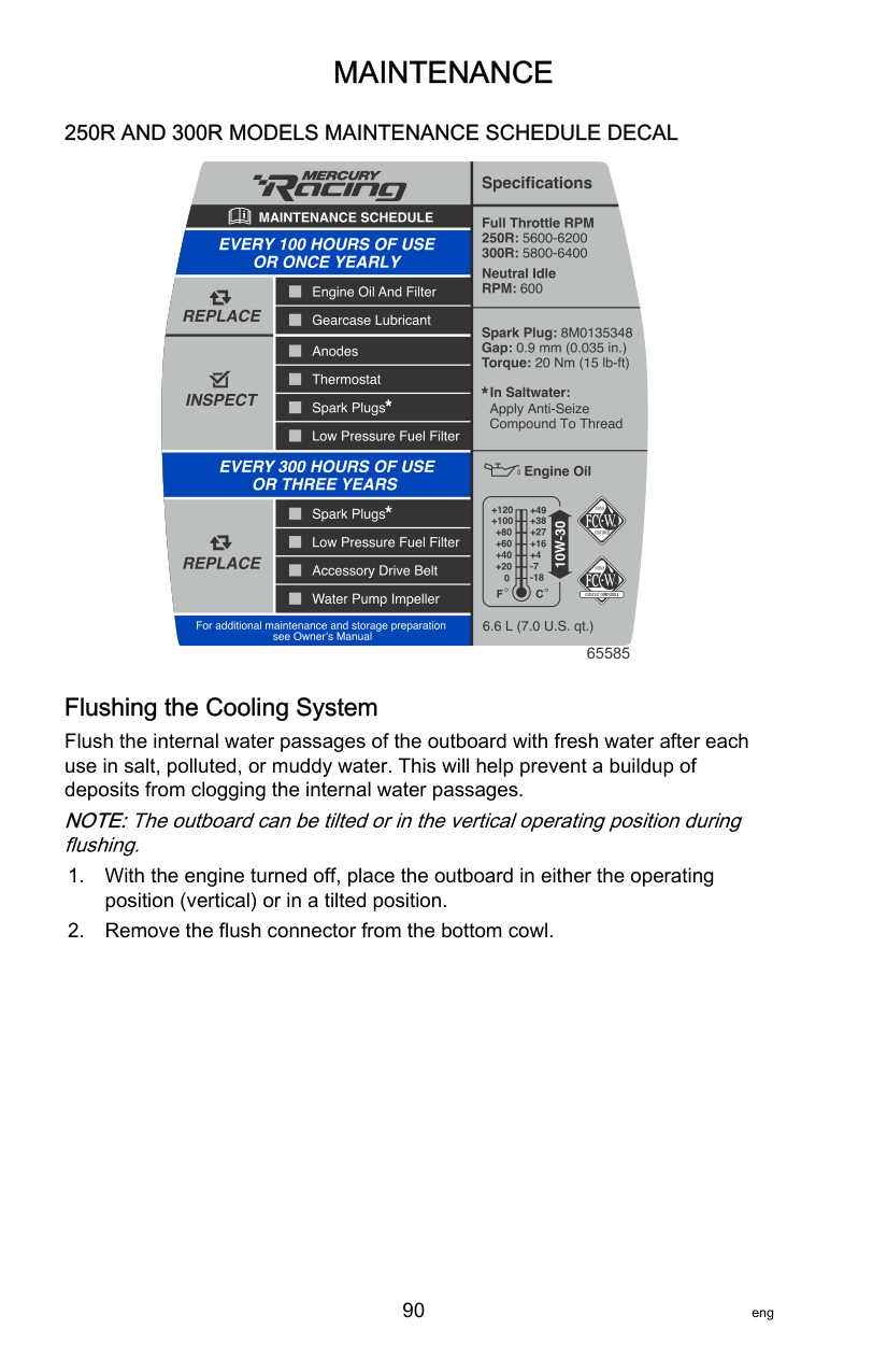

63415 Filter rotated 1/4 turn

a
b
63414
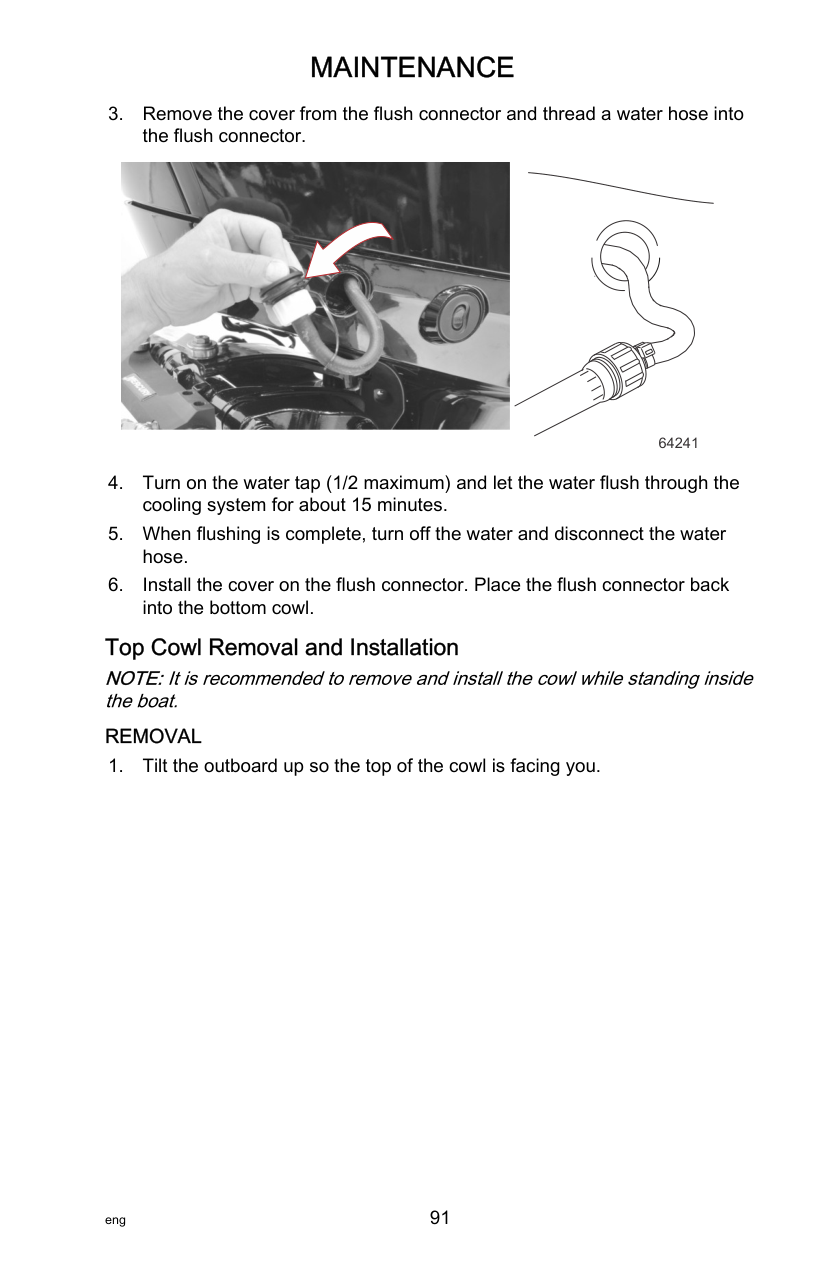

63416
|Tube Ref No.|Description|Where Used|Part No.| |---|---|---|---| |95|2-4-C with PTFE|Fuel filter grommet|92-802859A 1|
NOTE:If there is a boat mounted water‑separating fuel filter with a water‑in‑fuel sensor installed, the sensor harness would be connected to the boat mounted filter.
Corrosion Control Anode The outboard has corrosion control anodes at different locations. An anode helps protect the outboard against galvanic corrosion by sacrificing its metal to be slowly eroded instead of the outboard metals. Each anode requires periodic inspection, especially in saltwater which will accelerate the erosion. To maintain this corrosion protection, always replace the anode before it is 50% eroded. Never paint or apply a protective coating on the anode as this will reduce effectiveness of the anode.
Two anodes are located on the engine; one anode is on the gear housing and the other is on the bottom of the transom bracket assembly.

63472
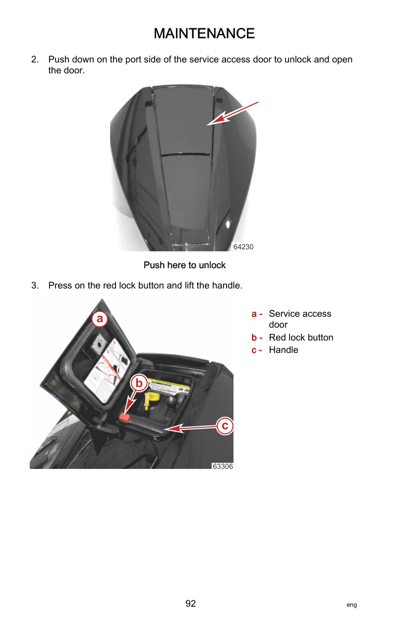
######################## Propeller Replacement
||!| |---|
WARNING| |---| |Rotating propellers can cause serious injury or death. Never operate the boat out of the water with a propeller installed. Before installing or removing a propeller, place the drive unit in neutral and activate the lanyard stop switch to prevent the engine from starting. Place a block of wood between the propeller blade and the anti‑ventilation plate.|

N
58237

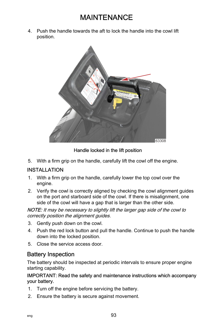
26901
64237
|Tube Ref No.|Description|Where Used|Part No.| |---|---|---|---| | |Extreme Grease|Propeller shaft|8M0071842| |95|2-4-C with PTFE|Propeller shaft|92-802859A 1|
############################# IMPORTANT: To prevent the propeller hub from corroding and seizing to the propeller shaft, especially in saltwater, always apply a liberal amount of the recommended lubricant to the entire propeller shaft at the recommended maintenance intervals and also each time the propeller is removed.
########################### FLO-TORQ II PROPELLER HUB KIT—25.4 MM (1 IN.) PROPELLER SHAFT
c
a b
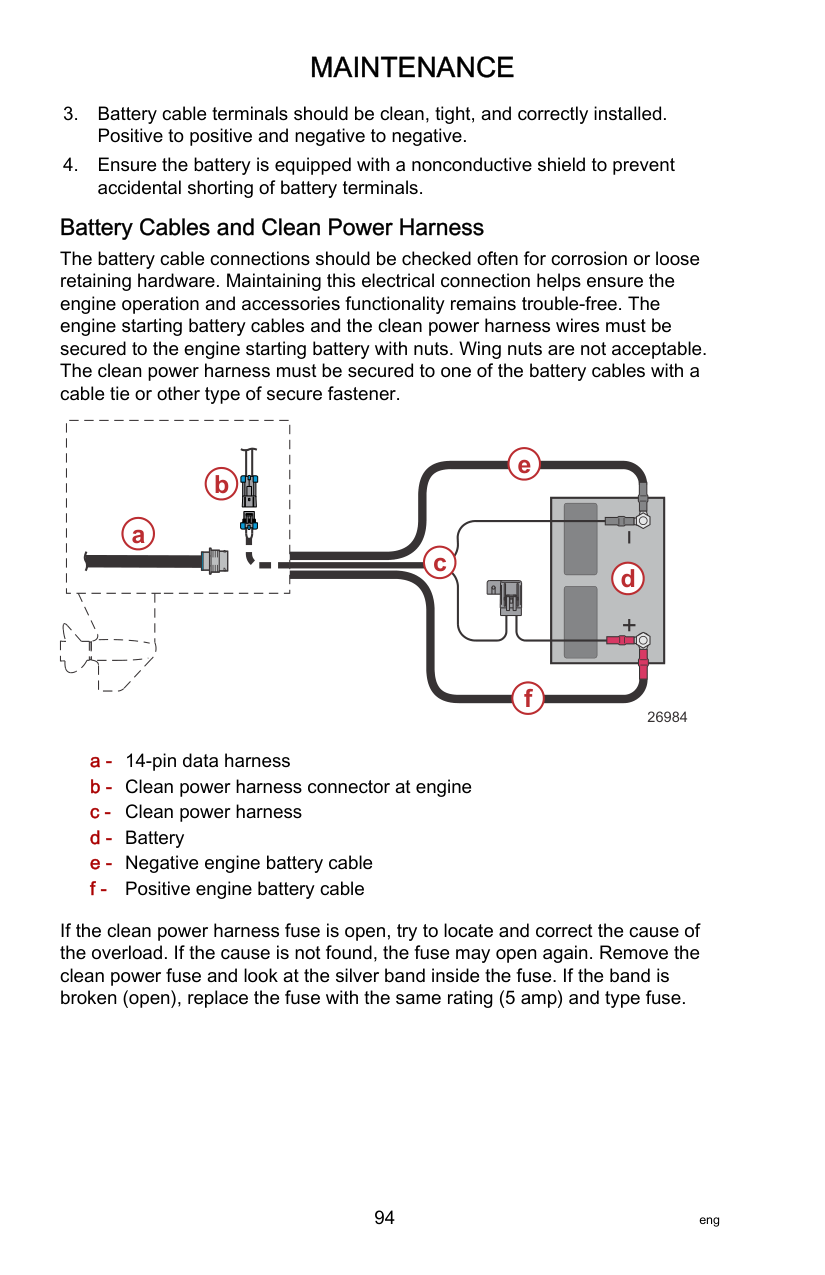
h
g
d e
| | |---| | |
| | | | | | | | | | |---|---|---|---|---|---|---|---|---|
f
45232
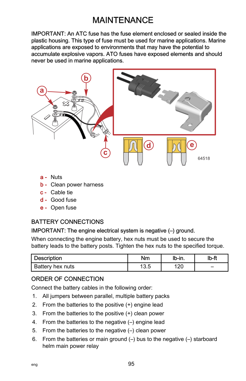
|Description|Nm|lb‑in.|lb‑ft| |---|---|---|---| |Locknut|75|–|55.3|
########################### FLO-TORQ IV PROPELLER HUB KIT—25.4 MM (1 IN.) PROPELLER SHAFT
c
a b
g
d e
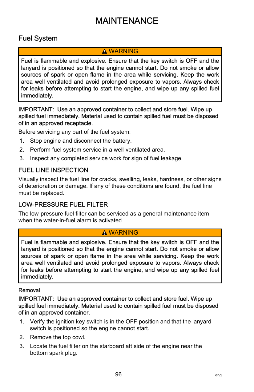

| | | | | | | | |---|---|---|---|---|---|---|
f
45248
|Description|Nm|lb‑in.|lb‑ft| |---|---|---|---| |Locknut|75|–|55.3|
SSR PROPELLER HUB KIT—25.4 MM (1 IN.) PROPELLER SHAFT IMPORTANT: The SSR was designed for use with only the 8 spline aft drive sleeve adapter—8M0109703. The use of any other aft drive sleeve adapter may result in a premature failure of the SSR hub and an increase in propeller vibration and noise. NOTE:The Flo‑Torq SSR hub is designed to have a small amount of free play when installed. This free play helps the SSR dampen the noise and vibration of the propeller. The propeller may move in and out up to 0.3175 cm (1/8 inch) and rotate up to 10 degrees when correctly installed.
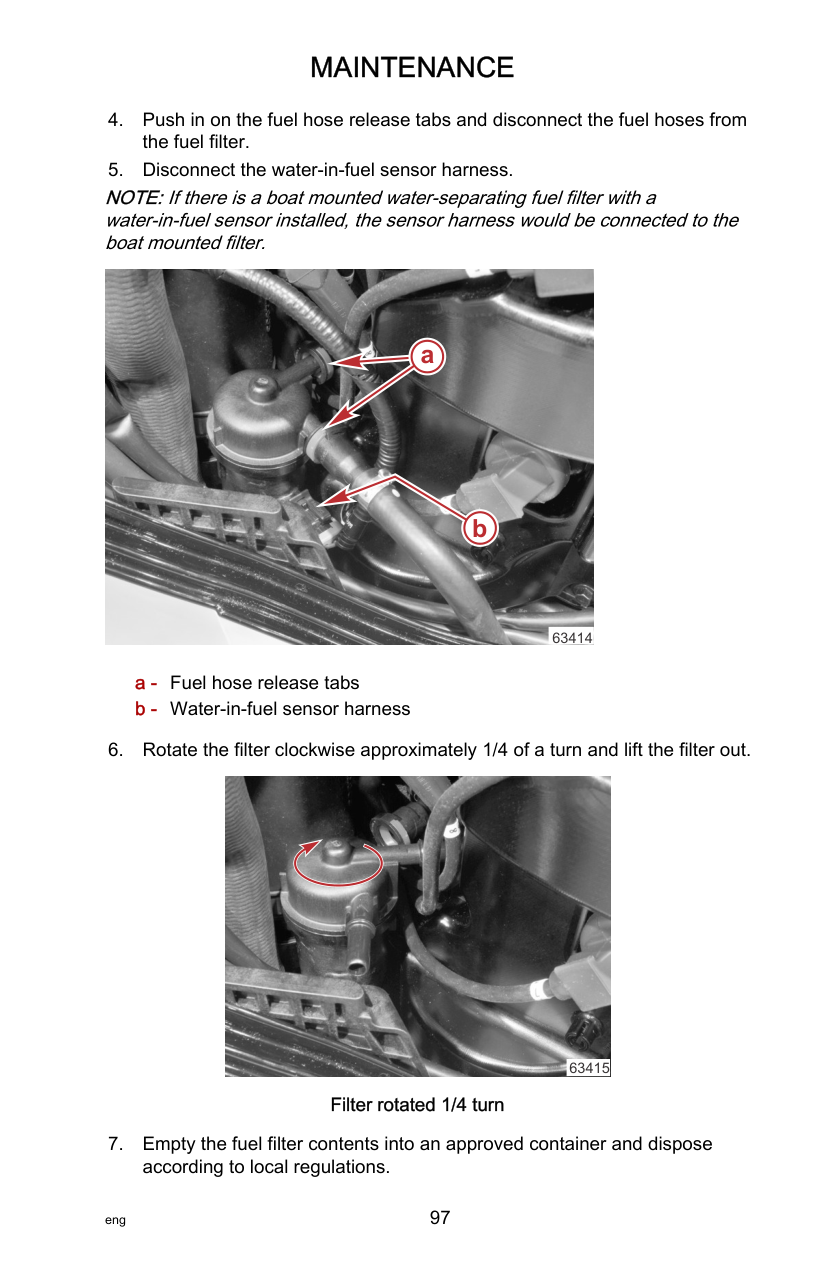
|Description|Nm|lb‑in.|lb‑ft| |---|---|---|---| |Locknut|135|–|100|
a
b
c d e
71777
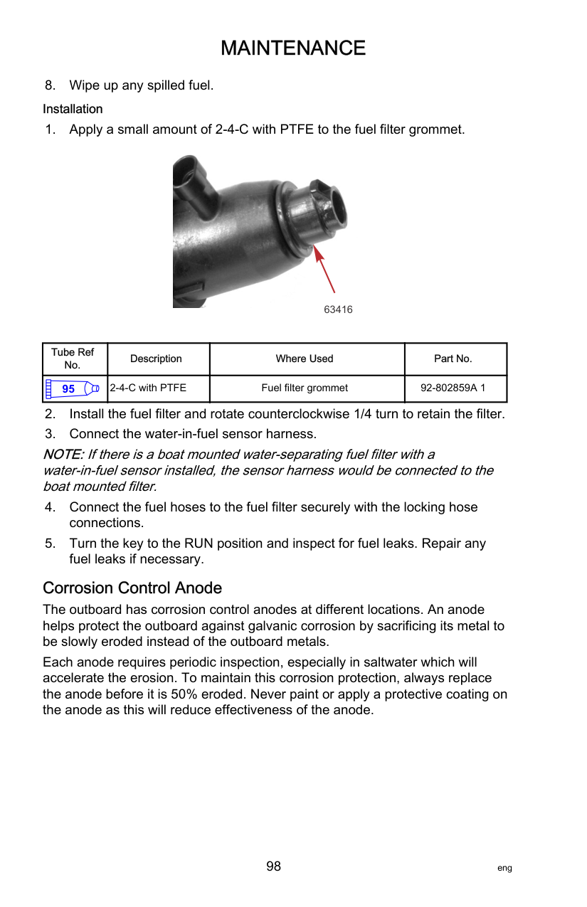
NOTE:If the tabbed locknut washer does not line up with the flat sides of the locknut, loosen the locknut, rotate the washer 90 degrees, and tighten the locknut to specified torque.
########################### SSR SOLID PROPELLER HUB KIT—25.4 MM (1 IN.) PROPELLER SHAFT
|Description|Nm|lb‑in.|lb‑ft| |---|---|---|---| |Locknut|74.6|–|55|
a b
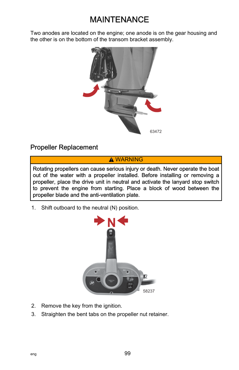
c d e
| | | |---|---| | | |
| | | |---|---| | | |
| | | |---|---| | | |
| | | |---|---| | | |
71786
######################## Propeller Replacement—31.75 mm (1‑1/4 in.) Diameter Propeller Shaft
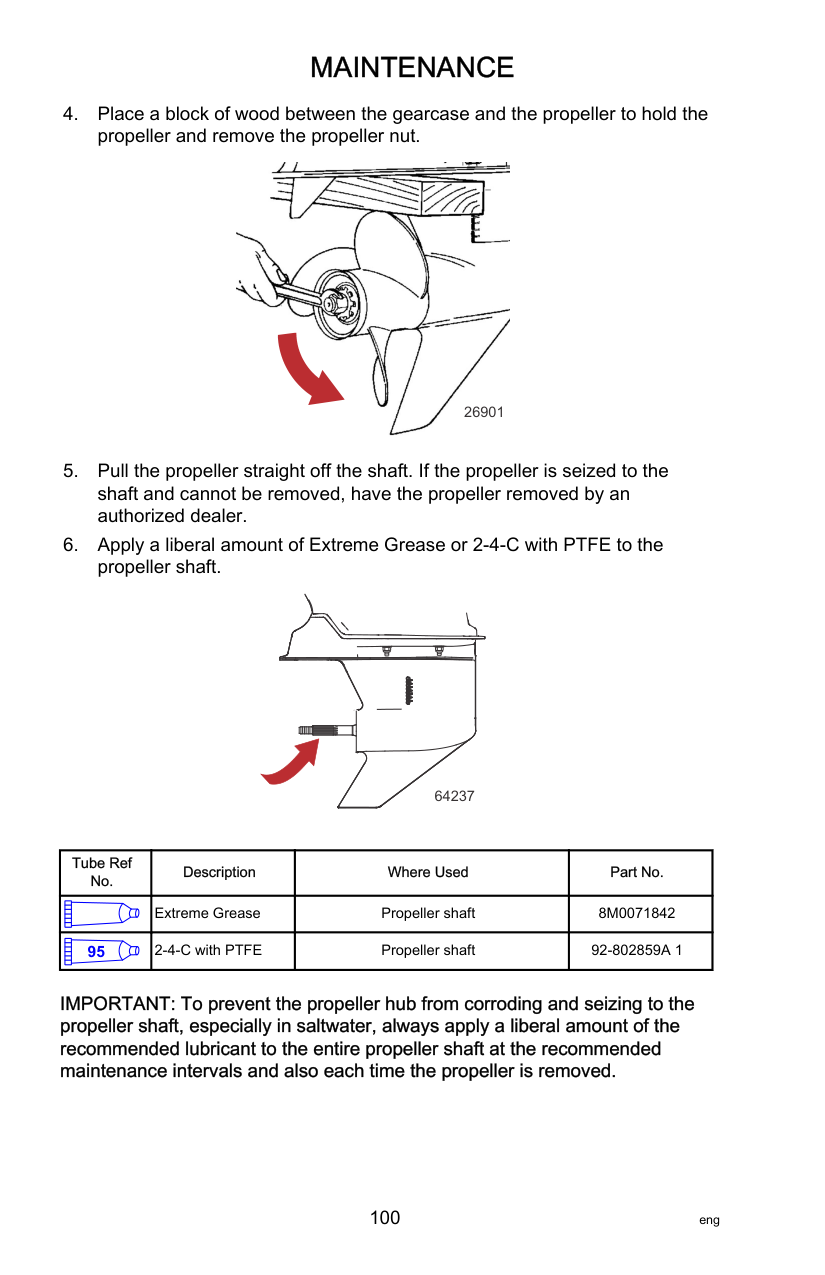
||!| |---|
WARNING| |---| |Rotating propellers can cause serious injury or death. Never operate the boat out of the water with a propeller installed. Before installing or removing a propeller, place the drive unit in neutral and activate the lanyard stop switch to prevent the engine from starting. Place a block of wood between the propeller blade and the anti‑ventilation plate.|

29592
|Tube Ref No.|Description|Where Used|Part No.| |---|---|---|---| | |Extreme Grease|Propeller shaft splines|8M0071842| |95|2-4-C with PTFE|Propeller shaft splines|92-802859A 1|
NOTE:Propellers used on the 31.75 mm (1‑1/4 in.) diameter propeller shaft require the heavy‑duty propeller hub kit.
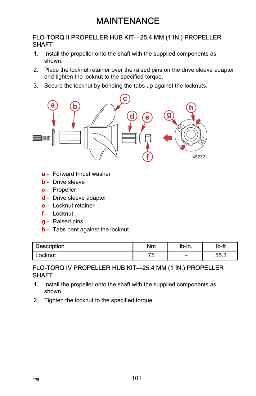
e
a b c d
f


| | | | | | | | | | |---|---|---|---|---|---|---|---|---|
44856
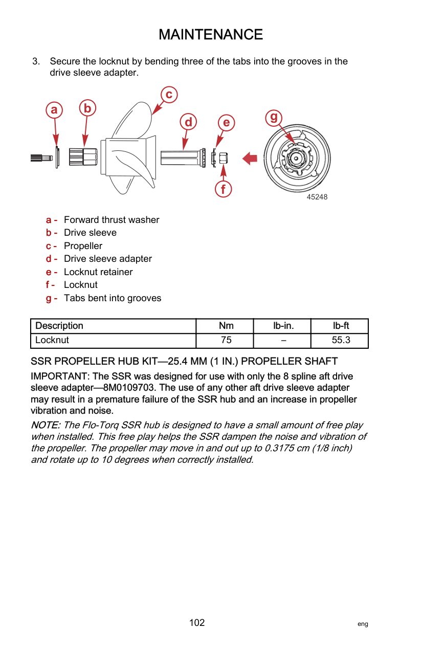
############################## 6. Place a block of wood between the gearcase and the propeller. Tightenthe propeller nut to the specified torque.

2691
|Description|Nm|lb‑in.|lb‑ft| |---|---|---|---| |Propeller nut|75|–|55.3|
Spark Plug Inspection and Replacement

63312 Spark plug boot
NOTE:Replace the spark plug if the electrode is worn; the insulator is rough, cracked, broken, or blistered; or if the precious metal is not visible on the spark plug electrode.
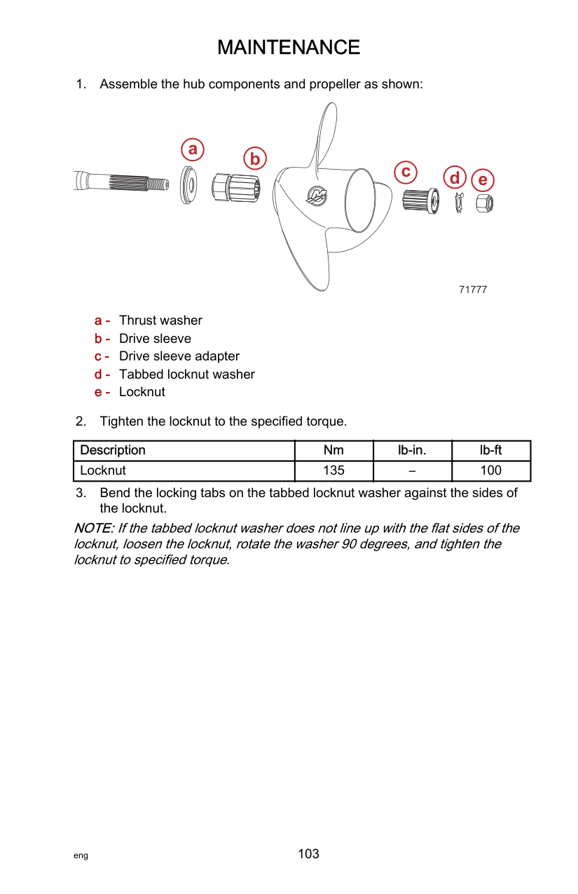
############################# IMPORTANT: The color of the plug may not accurately reflect its condition. To accurately diagnose a faulty plug, inspect the precious metal on the plug's electrode. If no precious metal is visible, replace the plug.
######## a
9381
a - Precious metal
| | | | | |---|---|---|---| | | | | | | | | | |
27848
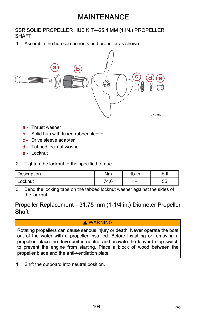
|Tube Ref No.|Description|Where Used|Part No.| |---|---|---|---| |81|Anti-Seize Compound|Spark plug threads|92-898101389|
|Description|Nm|lb‑in.|lb‑ft| |---|---|---|---| |Spark plug|20|177|–|

63315 Push the spark plug boot
######################## Fuses
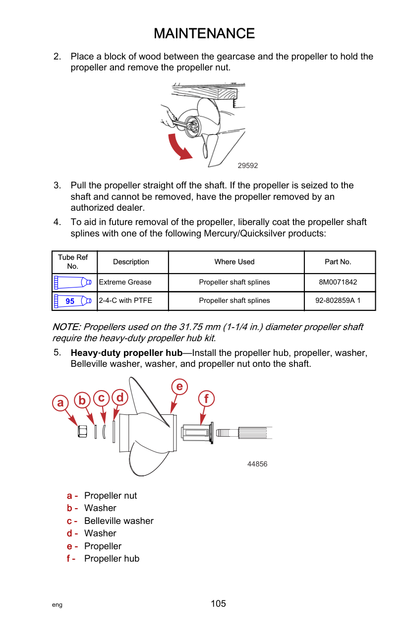
IMPORTANT: An ATC fuse has the fuse element enclosed or sealed inside the plastic housing. This type of fuse must be used for marine applications. Marine applications are exposed to environments that may have the potential to accumulate explosive vapors. ATO fuses have exposed elements and should never be used in marine applications.
The electrical wiring circuits on the outboard are protected from overload with fuses. If a fuse is open, try to locate and correct the cause of the overload. If the cause is not found, the fuse may open again.
############################## 1. Locate the fuse holder on the port side of the engine and remove thecover from the fuse holder.

63317
############################## 2. Remove the suspected open fuse and look at the silver band inside thefuse. If the band is broken (open), replace the fuse.
############################# IMPORTANT: Replace the fuse with a new fuse with the same amp rating.

d
i
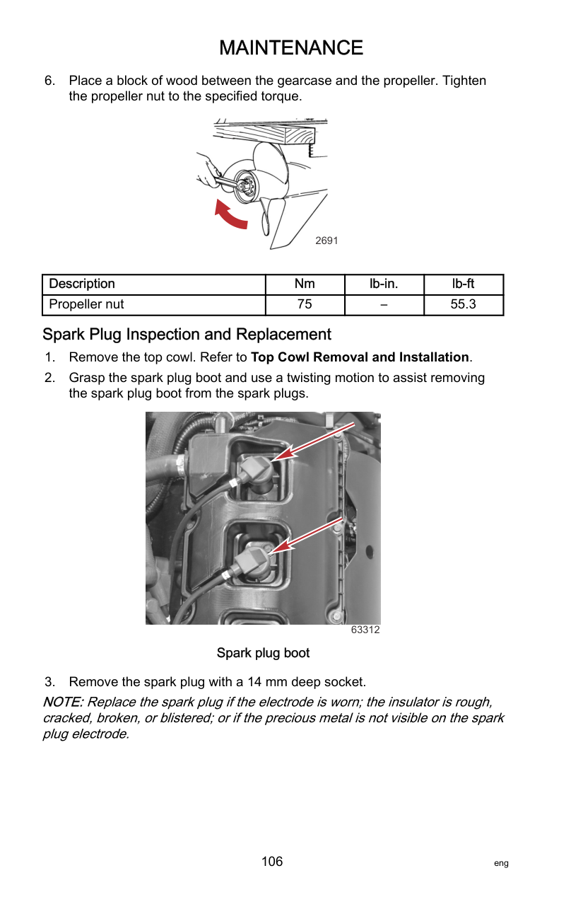

############################### 2020
20
2 10
SPARE FUSES
5
15
20
############# h k
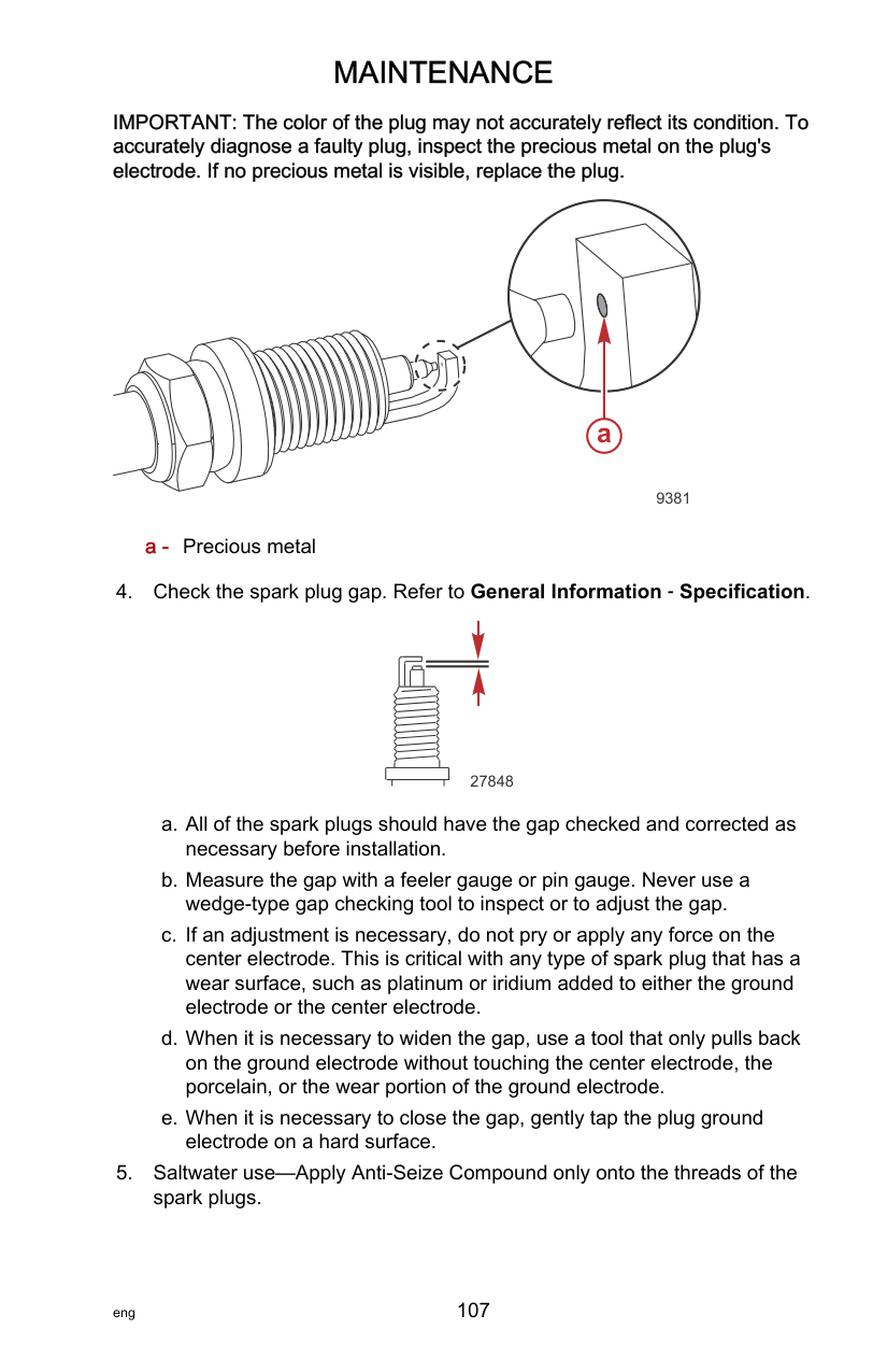
j
| | | | |---|---|---| | | | | | | | |
| | | | |---|---|---| | | | | | | | |
64390
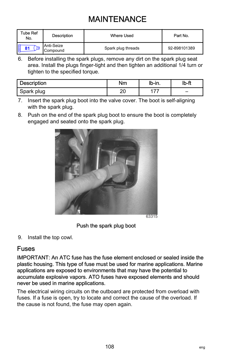
Alternator Drive Belt The alternator drive belt is located under the flywheel shroud–intake air induction plenum. The alternator drive belt inspection must be completed by an authorized Mercury dealer at the recommended interval. Refer to Inspection and Maintenance Schedule.
######################## Lubrication Points
|Tube Ref No.|Description|Where Used|Part No.| |---|---|---|---| | |Extreme Grease|Swivel bracket, tilt lock, propeller shaft|8M0071842|
|Tube Ref No.|Description|Where Used|Part No.| |---|---|---|---| |95|2-4-C with PTFE|Swivel bracket, tilt lock, tilt tube, propeller shaft|92-802859A 1|
############################## • Lubricate the swivel bracket and tilt lock through the grease fittings.

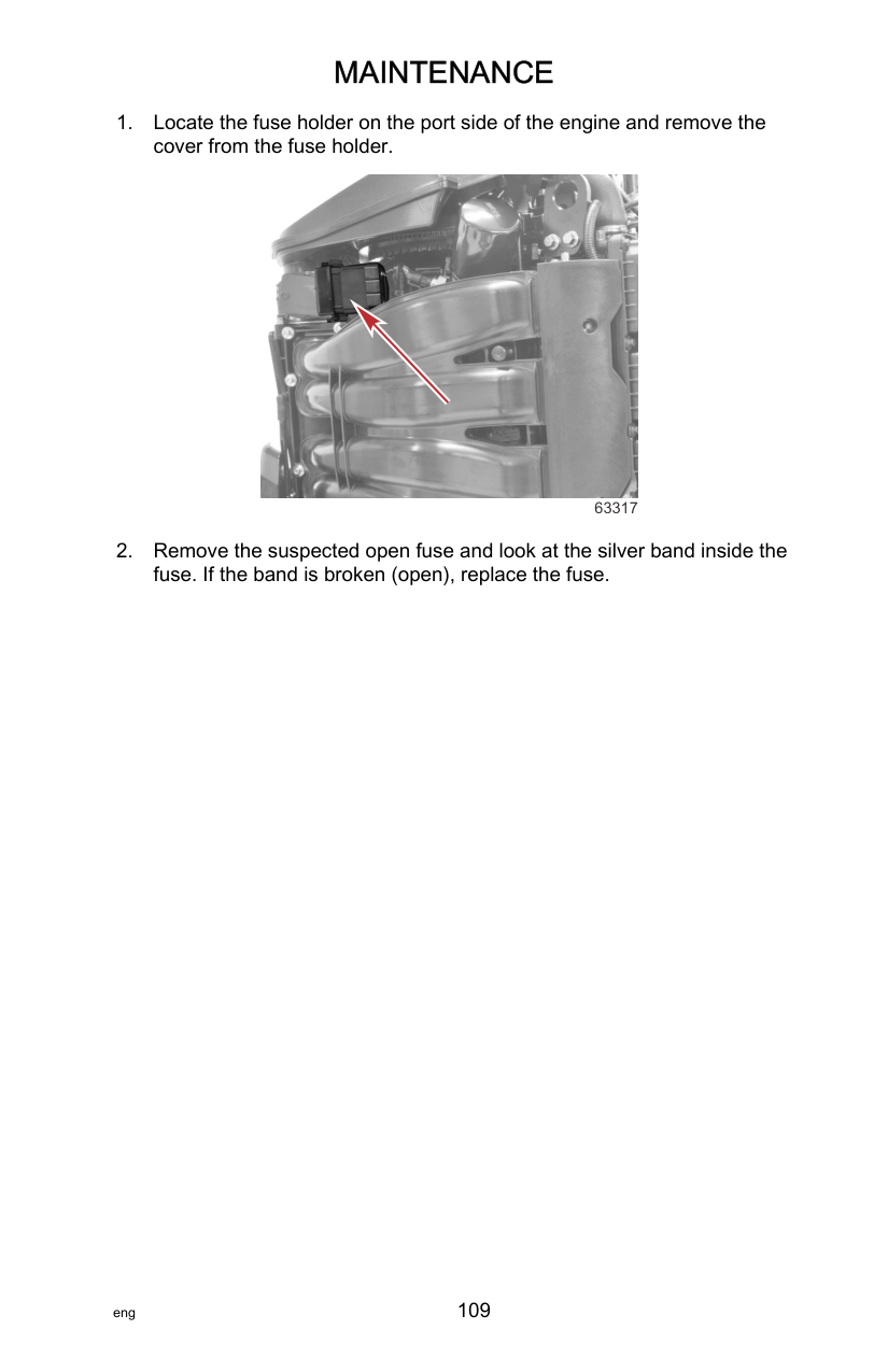
63792
############################## • Lubricate the tilt tube through the grease fitting.


64517
• Propeller shaft—Refer to Propeller Replacement for removal and
installation of the propeller. Apply a generous amount of lubricant to the entire propeller shaft to prevent the propeller hub from seizing to the shaft.
64237
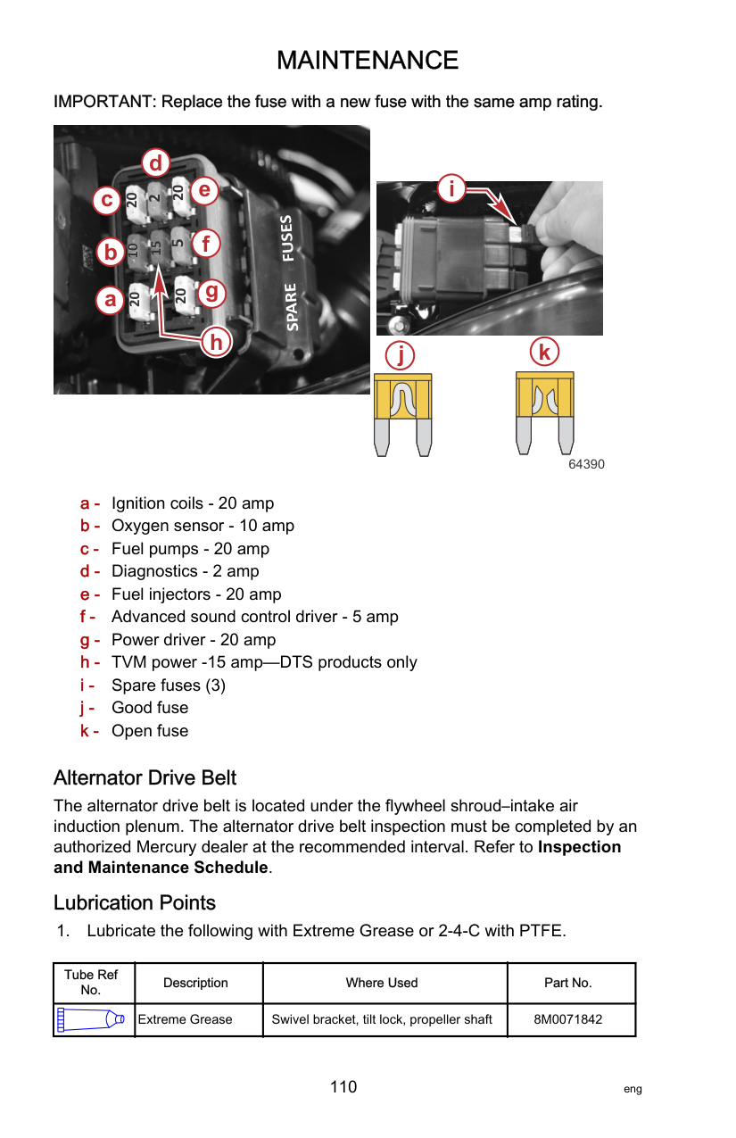

63797 Lubricate with oil
######################## Checking Power Trim Fluid
############################## 1. Tilt the outboard to the full up position and engage the tilt support lever.

27877
even with the bottom of the fill hole. Add Quicksilver or Mercury Precision Lubricant Power Trim and Steering Fluid. If not available, use automotive automatic transmission fluid (ATF).

28460
|Tube Ref No.|Description|Where Used|Part No.| |---|---|---|---| |114|Power Trim and Steering Fluid|Power trim system|92-858074K01|
######################## Checking Hydraulic Steering Fluid
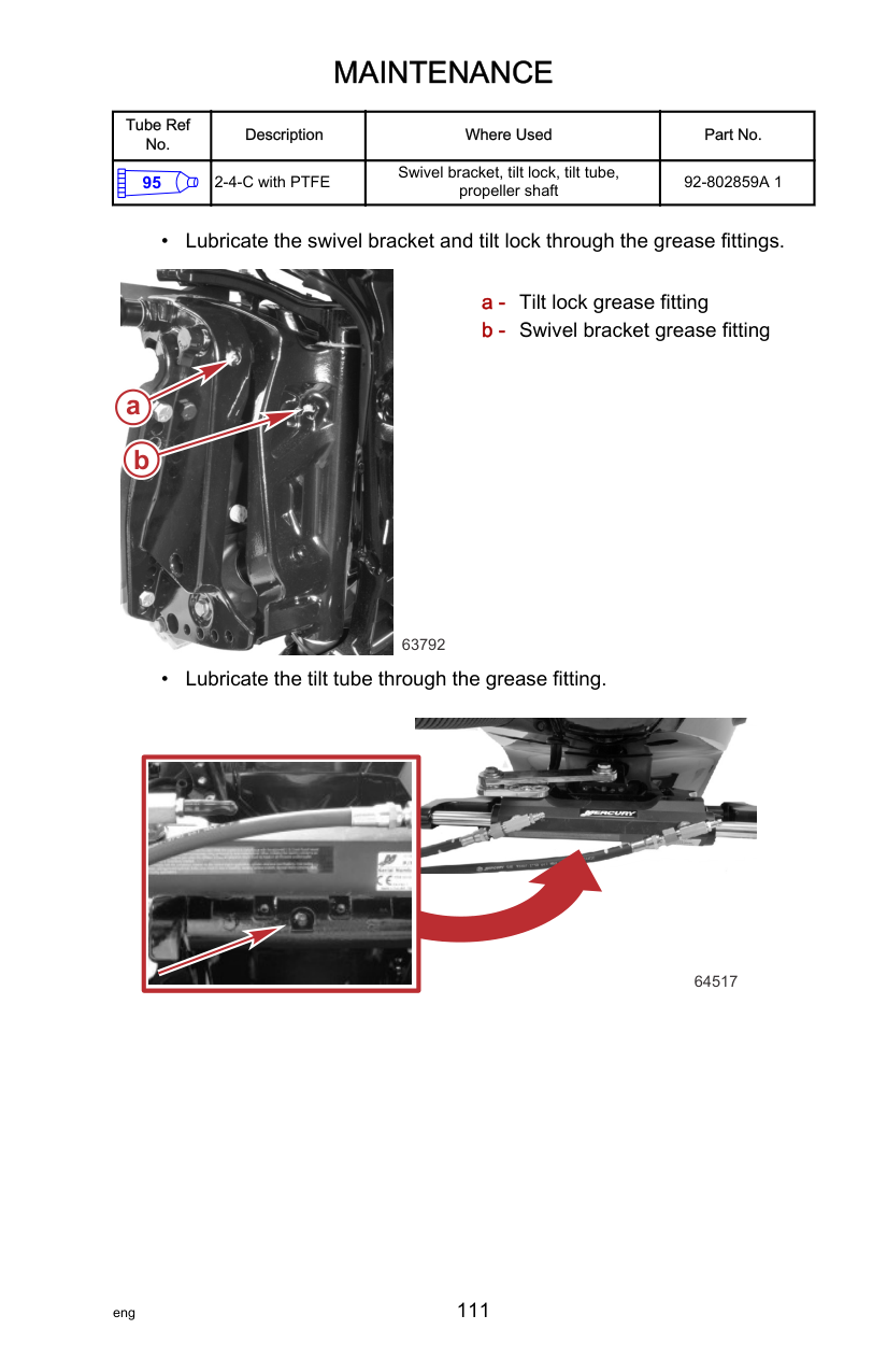
||!| |---|
WARNING| |---| |Dirt or contaminants in the hydraulic steering system can damage the steering system's internal components. Damaged components can lead to serious injury or death due to loss of boat control. Do not allow dirt or contamination to enter the helm, lines, or cylinder of this steering system and perform all hydraulic inspections, service, or assembly procedures in a clean work area.|
IMPORTANT: Check the hydraulic steering fluid level on a regular basis. The steering system must be full of fluid to ensure the steering helm will not introduce air into the steering system. A hydraulic steering system which has entrained air will have spongy or unresponsive steering control which could compromise the operator's ability to control the boat. On dual helm steering systems, always check the upper steering helm first. If the system must be purged of entrained air, one person may not be able to completely fill and purge the air from the steering system. See your dealer if you have questions on your steering system or refer to the installation instructions included with your steering system.
######################## Checking Power Steering Fluid
||!| |---|
WARNING| |---| |Dirt or contaminants in the hydraulic steering system can damage the steering system's internal components. Damaged components can lead to serious injury or death due to loss of boat control. Do not allow dirt or contamination to enter the helm, lines, or cylinder of this steering system and perform all hydraulic inspections, service, or assembly procedures in a clean work area.|
Remove the power steering cover and fill cap to check the fluid level. The fluid level should be slightly below the bottom of the fill hole. Use Synthetic Power Steering Fluid SAE 0W‑30, if needed.

29315
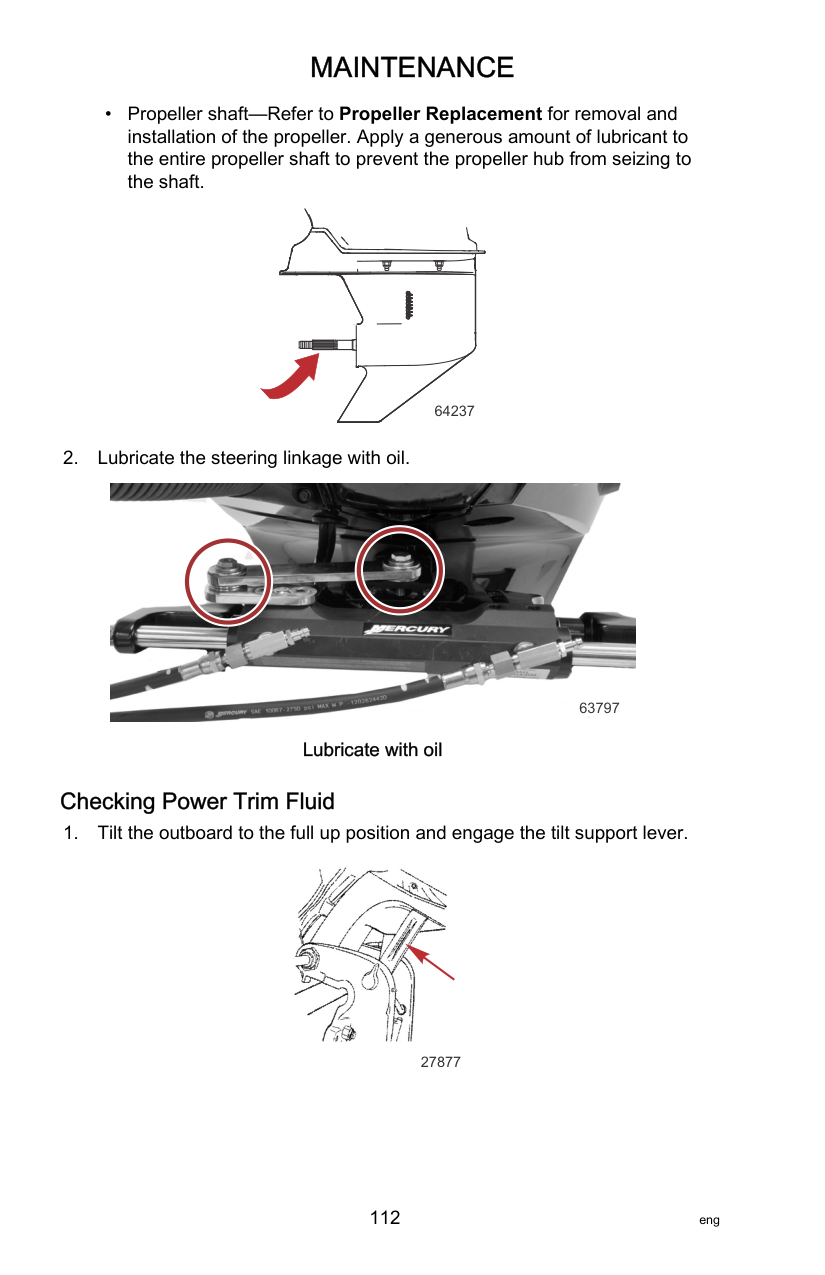
|Tube Ref No.|Description|Where Used|Part No.| |---|---|---|---| |138|Synthetic Power Steering Fluid SAE 0W-30|Power steering system|92-858077K01|
Changing Engine Oil and Filter ENGINE OIL CAPACITY Engine oil capacity is approximately 6.6 liter (7.0 US qt).
IMPORTANT: Tilt the outboard out/up past vertical for approximately one minute to allow any trapped oil to drain back to the oil sump.
########################### OIL CHANGE ON LAND
IMPORTANT: Do not loosen the oil drain valve more than 2‑1/2 turns. The oil seal could get damaged beyond 2‑1/2 turns.
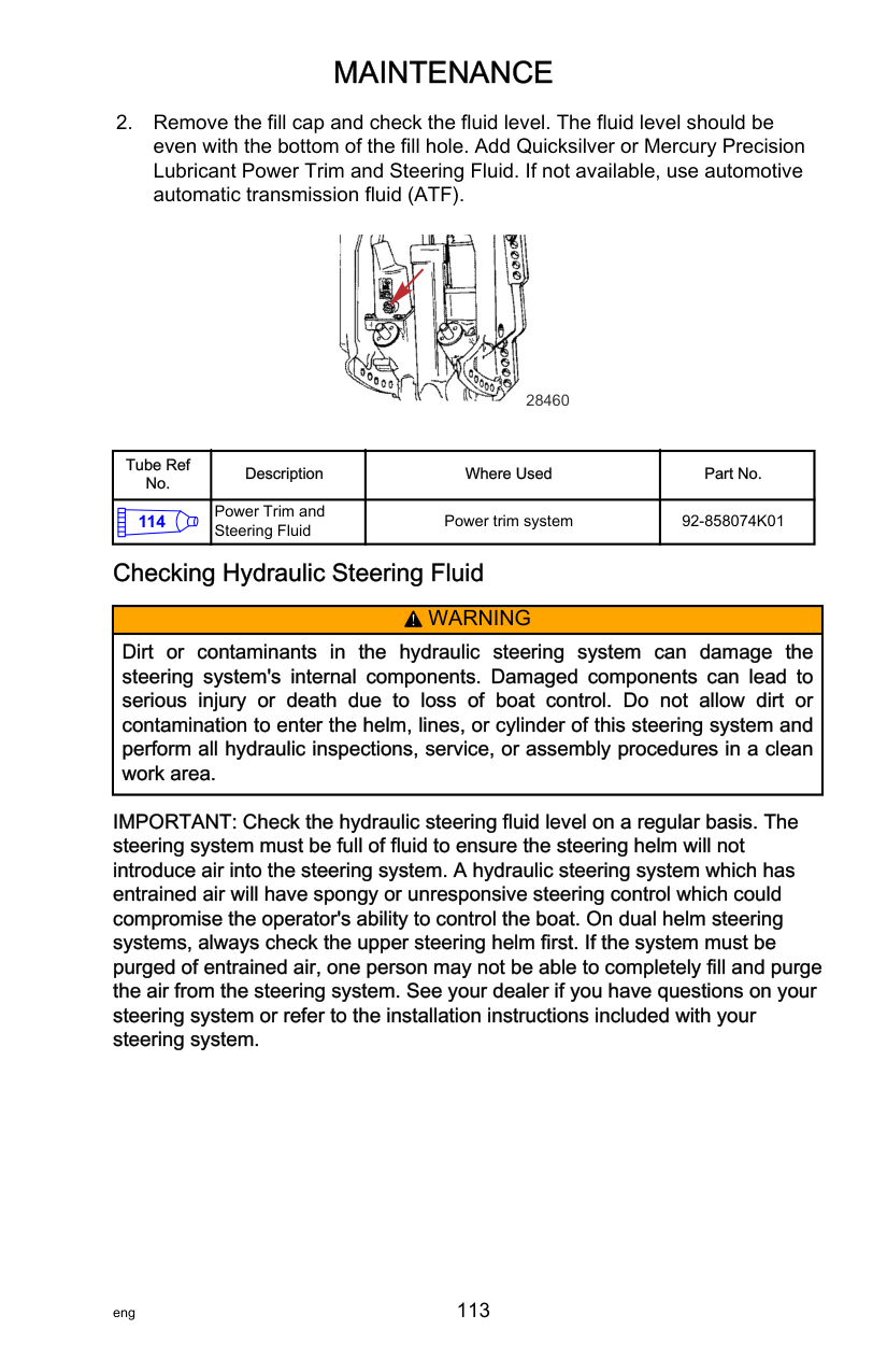
IMPORTANT: Overtightening the oil drain valve can damage the oil sump.
|Description|Nm|lb‑in.|lb‑ft| |---|---|---|---| |Oil drain valve|15|132.7|–|

a

1 22-
b
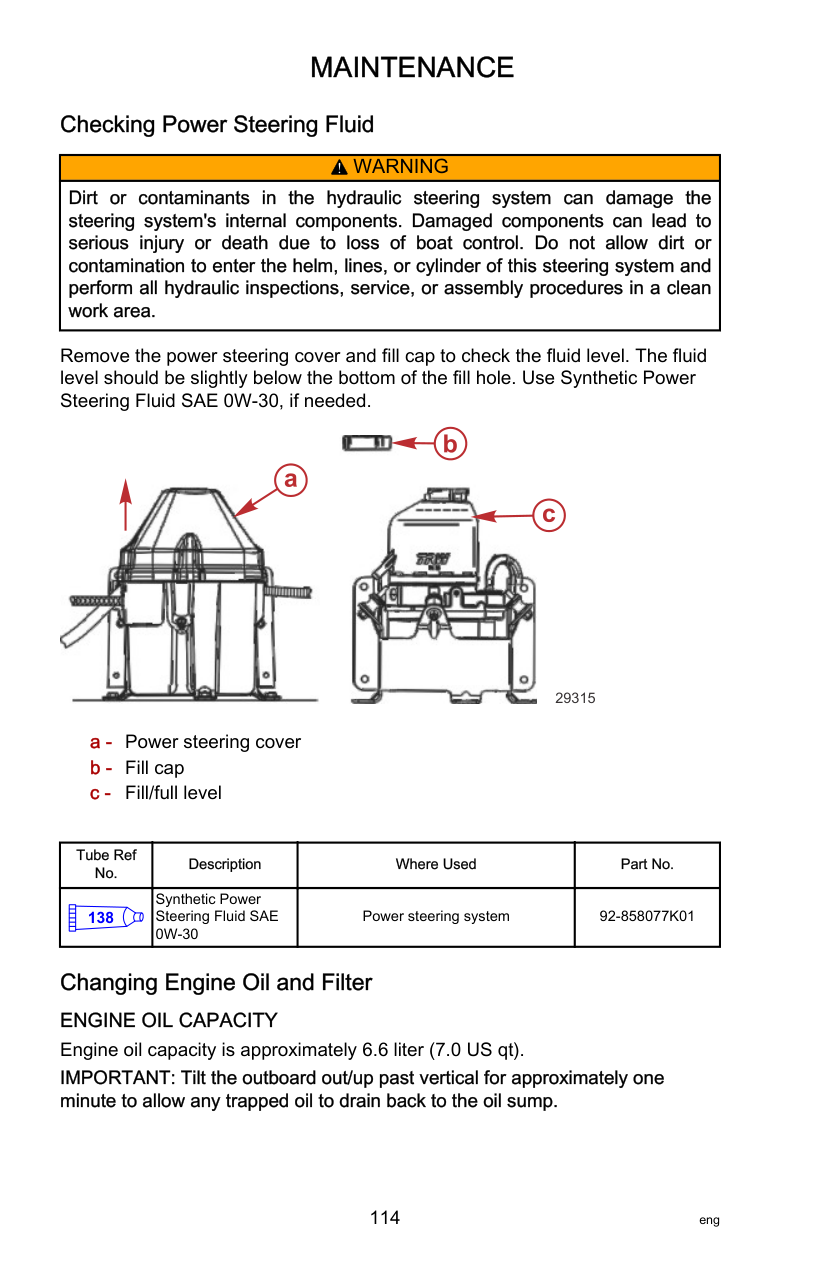
################### c
63398
########################### OIL CHANGE ON WATER

64230 Push here to unlock

b
a
63845
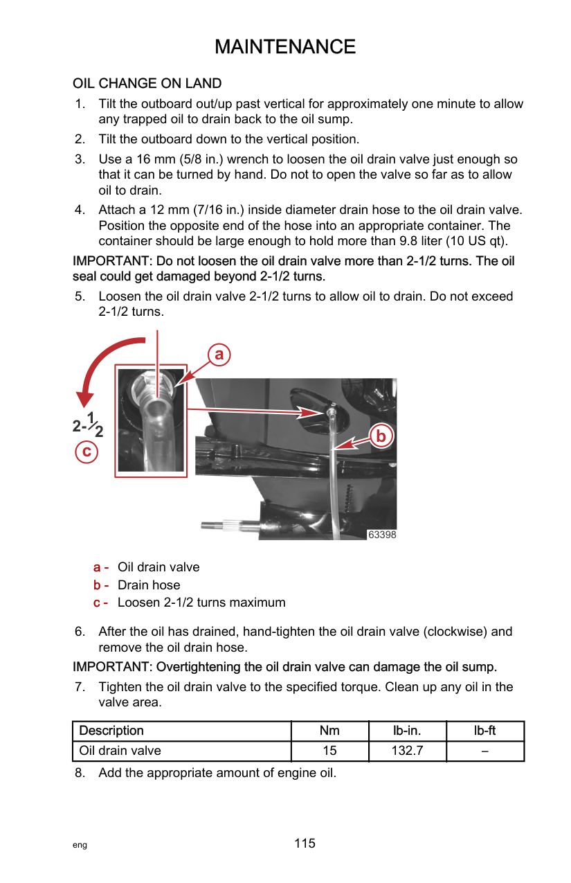
a - Crankcase oil pump b - Oil drain hose
|Crankcase Oil Pump|802889A1| |---|---| |
11591|Aids in the removal of engine oil without draining the crankcase.| |Oil Drain Hose|8M0129230| |
64627|Aids in the removal of engine oil without draining the crankcase. Connect to the crankcase oil pump.|

a
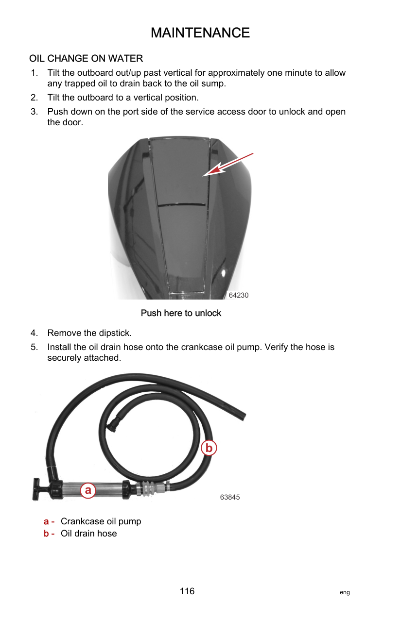
b
63843
|Oil Filter Wrench|91‑889277| |---|---| |5221|Aids in the removal of the oil filter.|
a - Oil filter b - Drain hose

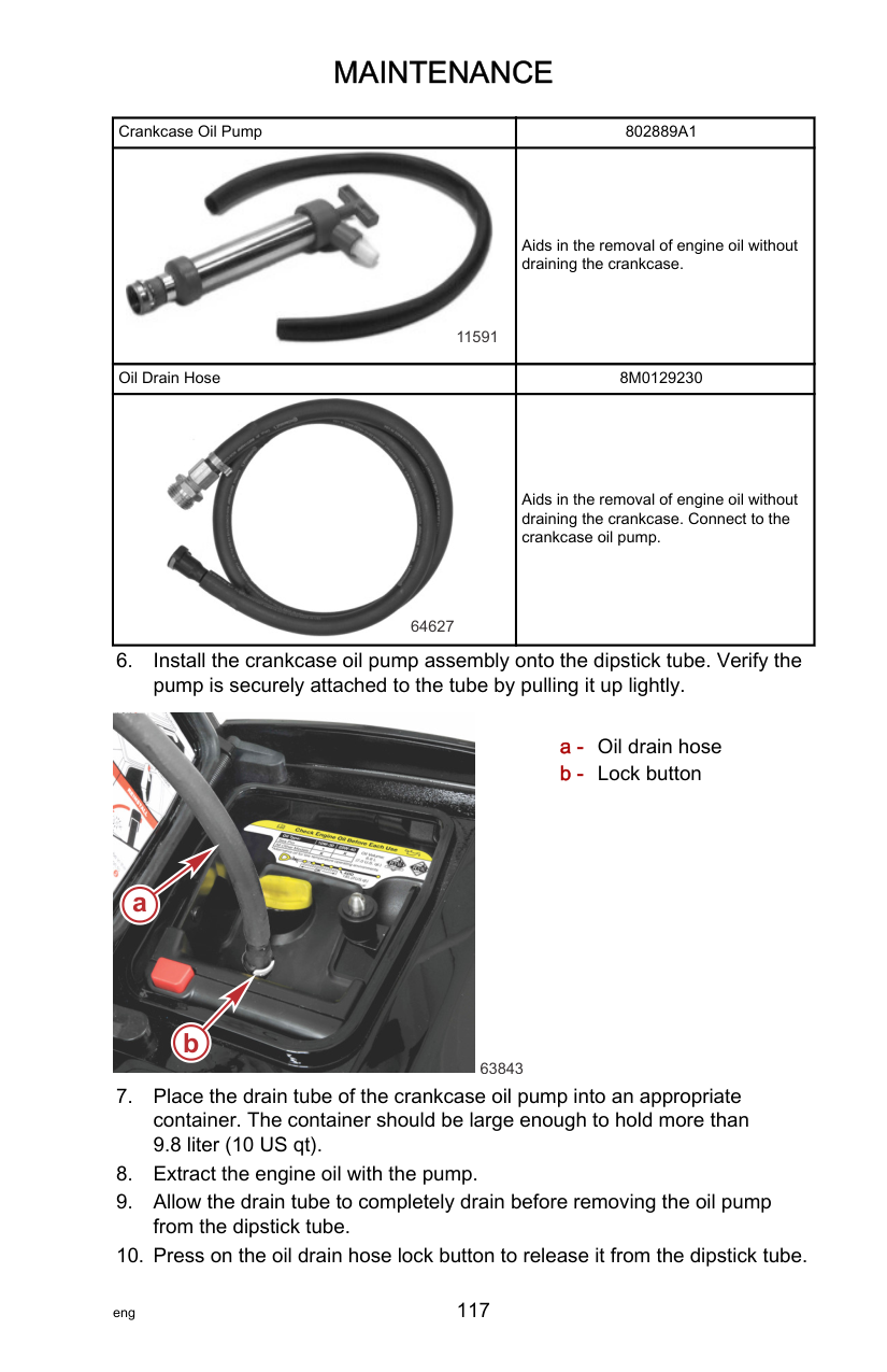
a
b
63399
########################### OIL FILLING
Remove the oil fill cap and add approximately 6.6 liter (7.0 US qt) of the recommended oil. This will bring the oil level within the operating range.

a - Oil fill cap b - Dipstick
a
b
63401
NOTE:It is not necessary to check the oil level immediately after changing the
oil. The engine must be run for a while and then turned off for one hour or longer before checking the oil level. Refer toChecking Engine Oil Level.

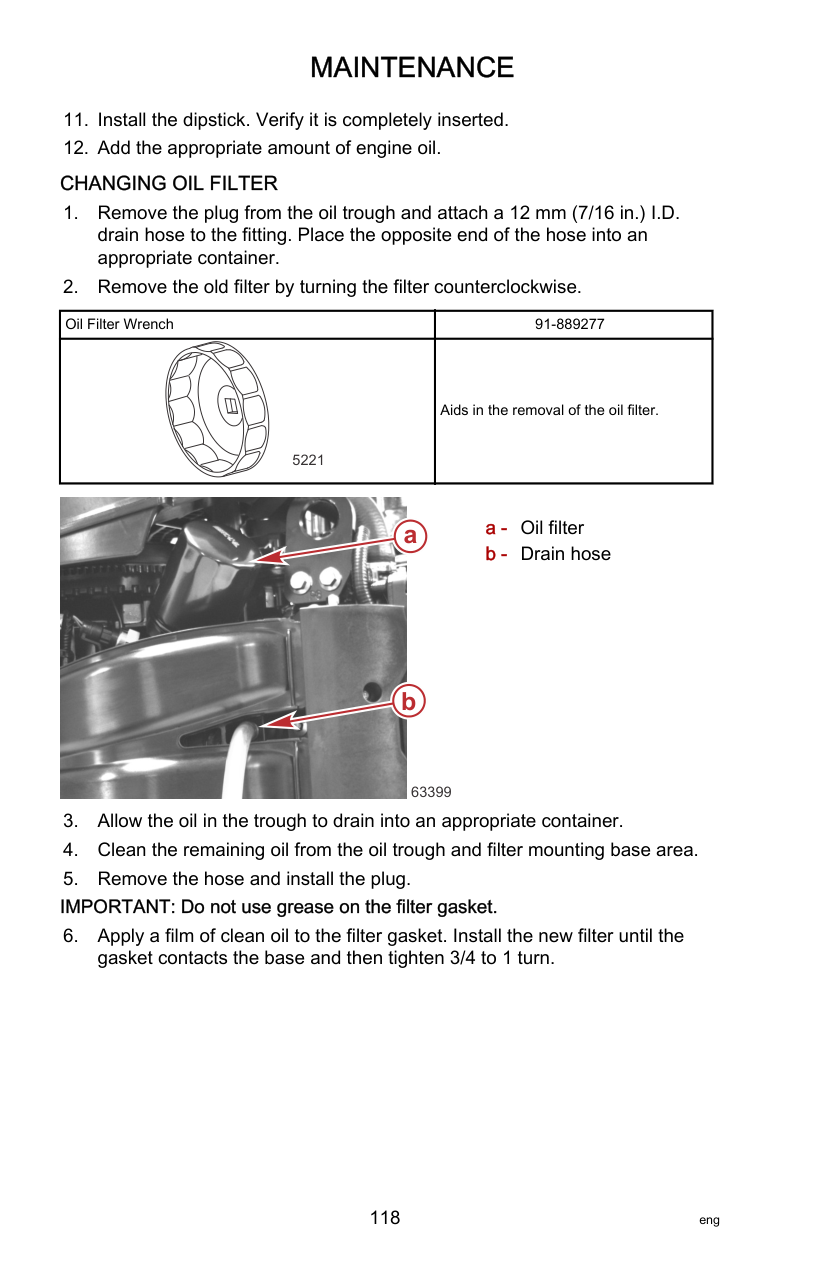


######################## Checking Engine Oil Level
After the engine oil has been changed, the engine should be run for a few minutes and then turned off, allowing one hour or longer before checking the oil level.
############################# IMPORTANT: For an accurate oil level reading, the engine must be vertical for several minutes before removing the dipstick.
63468
############################# Oil level example
DIPSTICK BEAD OIL LEVEL OVERVIEW New oil (level) may be difficult to identify which is why the crosshatch between the beads are part of the dipstick assembly. When checking the oil level, if oil is on any of the five oil range beads or four crosshatch, the oil level is within the safe operating range. When the oil level is only on the lowest oil range bead, the operator can add 1.8 Liter (2 US qt) of oil and the level will remain within the safe operating range. When the oil becomes dark from hours of product use, it will be easier to identify the oil level on the dipstick.

#### MAINTENANCE
############################# IMPORTANT: Repeated removal and insertion of the dipstick to check the oil level will subsequently deposit oil further up the dipstick tube which potentially may cause an error reading the oil level.
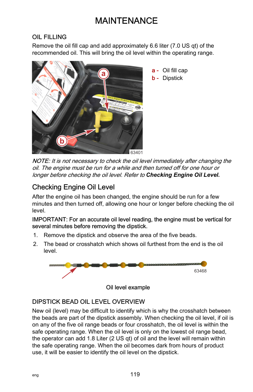
a
c
b 65510
a - Safe operating range b - General area after an oil change c - Add 1.8 Liter (2 US qt) of oil
######################## Exhaust Water Strainer Inspection
############################# IMPORTANT: The water strainer is an integral component of the cooling system. It should be inspected every 100 hours of operation or once a year, whichever occurs first.
There are two types of water strainer. Type 1 is an inline pencil‑type strainer. Type 2 is a screw‑in cross‑flow type. Follow the instructions that apply to your engine and water strainer type.
########################### TYPE 1

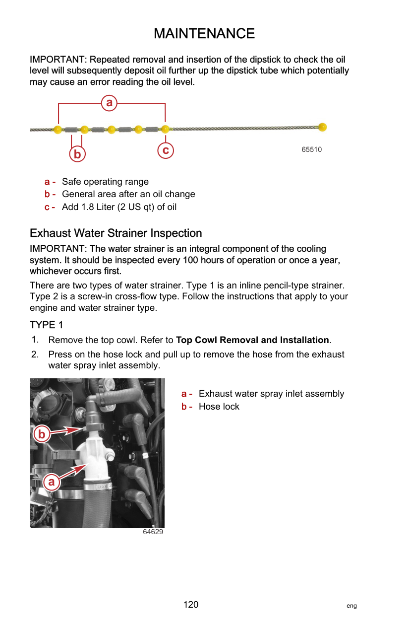
64629

64630 Strainer

64631
########################### TYPE 2

remove it from the water fitting in the upper exhaust tube. a

b
c
68702

68703
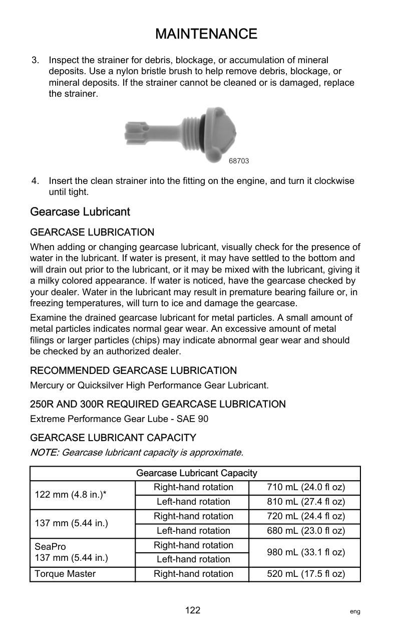
Gearcase Lubricant GEARCASE LUBRICATION When adding or changing gearcase lubricant, visually check for the presence of water in the lubricant. If water is present, it may have settled to the bottom and will drain out prior to the lubricant, or it may be mixed with the lubricant, giving it a milky colored appearance. If water is noticed, have the gearcase checked by your dealer. Water in the lubricant may result in premature bearing failure or, in freezing temperatures, will turn to ice and damage the gearcase. Examine the drained gearcase lubricant for metal particles. A small amount of metal particles indicates normal gear wear. An excessive amount of metal filings or larger particles (chips) may indicate abnormal gear wear and should be checked by an authorized dealer. RECOMMENDED GEARCASE LUBRICATION Mercury or Quicksilver High Performance Gear Lubricant. 250R AND 300R REQUIRED GEARCASE LUBRICATION Extreme Performance Gear Lube ‑ SAE 90 GEARCASE LUBRICANT CAPACITY NOTE:Gearcase lubricant capacity is approximate.
|Gearcase Lubricant Capacity|Gearcase Lubricant Capacity|Gearcase Lubricant Capacity| |---|---|---| |122 mm (4.8 in.)*|Right‑hand rotation|710 mL (24.0 fl oz)| |122 mm (4.8 in.)*|Left‑hand rotation|810 mL (27.4 fl oz)| |137 mm (5.44 in.)|Right‑hand rotation|720 mL (24.4 fl oz)| |137 mm (5.44 in.)|Left‑hand rotation|680 mL (23.0 fl oz)| |SeaPro 137 mm (5.44 in.)|Right‑hand rotation|980 mL (33.1 fl oz)| |SeaPro 137 mm (5.44 in.)|Left‑hand rotation|980 mL (33.1 fl oz)| |Torque Master|Right‑hand rotation|520 mL (17.5 fl oz)|
|Gearcase Lubricant Capacity|Gearcase Lubricant Capacity|Gearcase Lubricant Capacity| |---|---|---| |Sport Master|Right‑hand rotation|620 mL (21.0 fl oz)| |Sport Master|Left‑hand rotation|620 mL (21.0 fl oz)|
*Early model 4.8 in. gearcase bearing carriers may have the lubricant level plug located at the 3 o’clock position, requiring a slightly lower volume of gear lubricant.
########################### DRAINING AND FILLING THE GEARCASE - 122 MM (4.8 IN.) Draining Gearcase
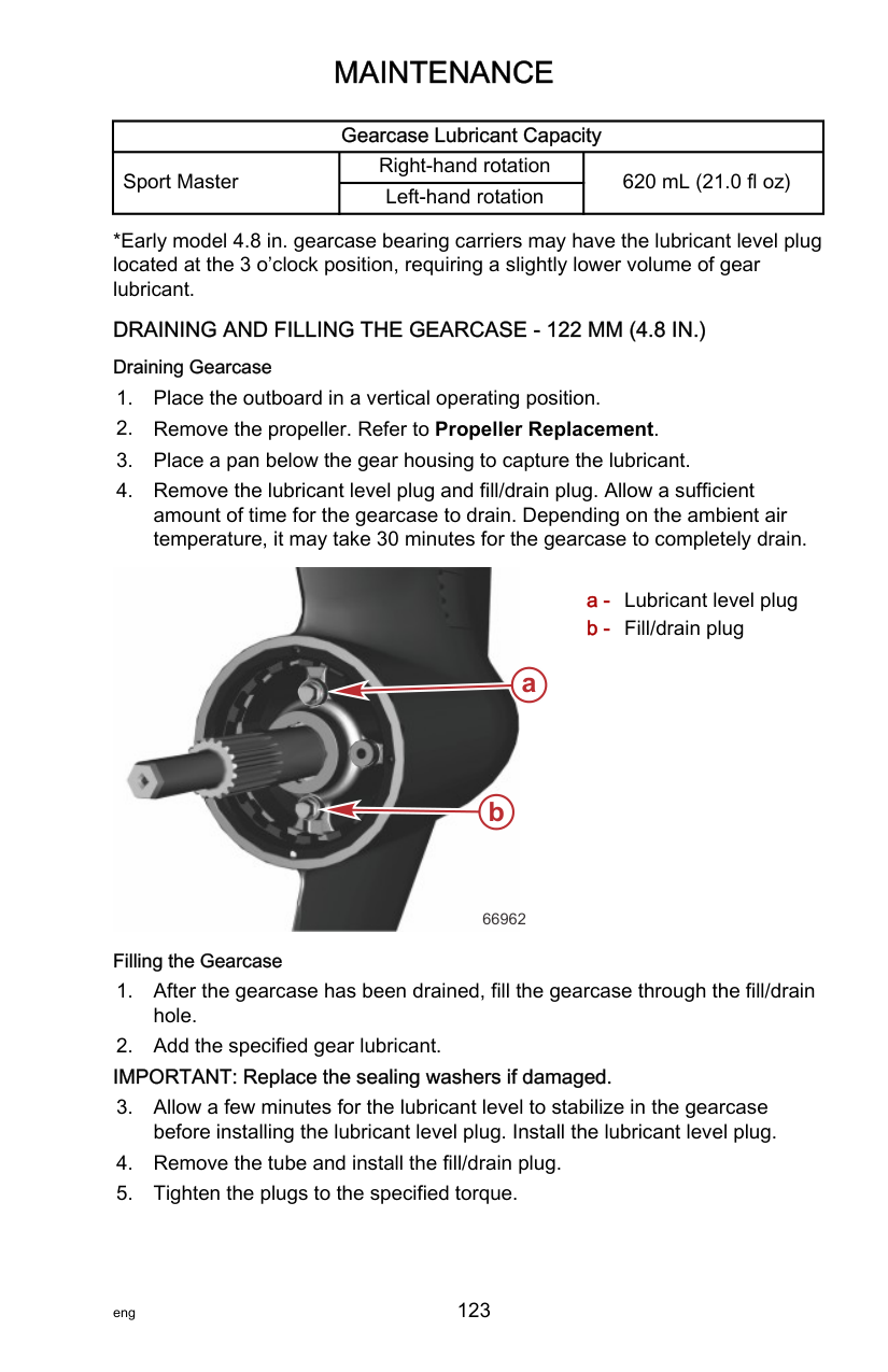


a - Lubricant level plug b - Fill/drain plug

a
b
66962
Filling the Gearcase
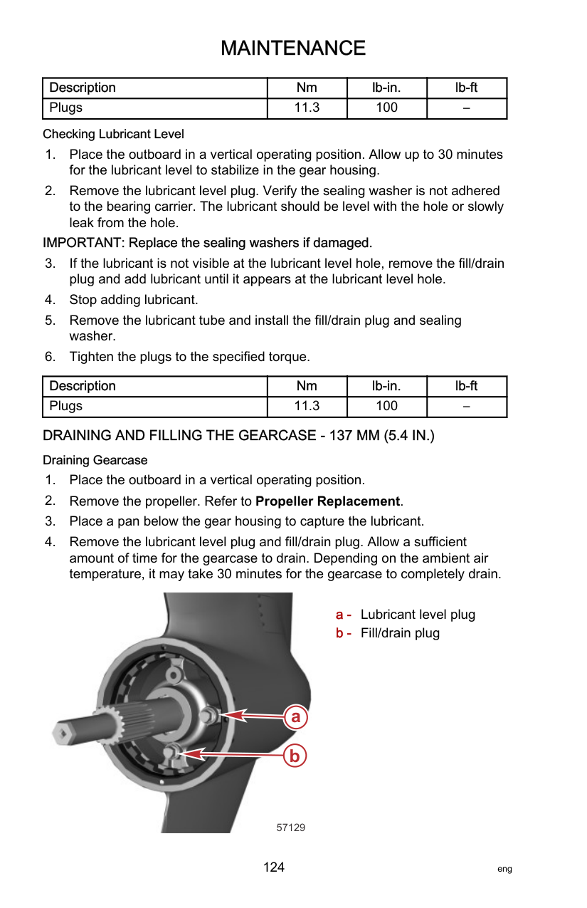
|Description|Nm|lb‑in.|lb‑ft| |---|---|---|---| |Plugs|11.3|100|–|
Checking Lubricant Level
IMPORTANT: Replace the sealing washers if damaged.
|Description|Nm|lb‑in.|lb‑ft| |---|---|---|---| |Plugs|11.3|100|–|
########################### DRAINING AND FILLING THE GEARCASE - 137 MM (5.4 IN.) Draining Gearcase
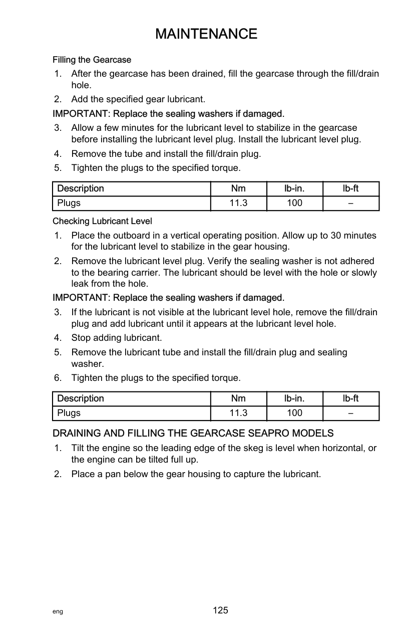

####### a b
57129
Filling the Gearcase
|Description|Nm|lb‑in.|lb‑ft|
|---|---|---|---| |Plugs|11.3|100|–|
Checking Lubricant Level
IMPORTANT: Replace the sealing washers if damaged.
|Description|Nm|lb‑in.|lb‑ft| |---|---|---|---| |Plugs|11.3|100|–|
########################### DRAINING AND FILLING THE GEARCASE SEAPRO MODELS


a - Lubricant level plug b - Fill/drain plug c - Leading edge of skeg is
level
a
bc
65602
Filling the Gearcase
IMPORTANT: Replace the sealing washers if damaged.
|Description|Nm|lb‑in.|lb‑ft| |---|---|---|---| |Plugs|11.3|100|–|
Checking Lubricant Level
IMPORTANT: Replace the sealing washers if damaged.
|Description|Nm|lb‑in.|lb‑ft| |---|---|---|---| |Plugs|11.3|100|–|
Storage Preparation The major consideration in preparing your outboard for storage is to protect it from rust, corrosion, and damage caused by freezing of trapped water. The following storage procedures should be followed to prepare your outboard for out of season storage or prolonged storage (two months or longer).
|NOTICE| |---| |Without sufficient cooling water, the engine, the water pump, and other components will overheat and suffer damage. Provide a sufficient supply of water to the water inlets during operation.|
FUEL SYSTEM IMPORTANT: Gasoline containing alcohol (ethanol or methanol) can cause a formation of acid during storage and can damage the fuel system. If the gasoline being used contains alcohol, it is advisable to drain as much of the remaining gasoline as possible from the fuel tank, remote fuel line, and engine fuel system. IMPORTANT: This outboard is equipped with a closed fuel system. Fuel within the engine's fuel system, other than the fuel tank, will remain stable during normal storage periods without the addition of fuel treatment stabilizers.
Fill the fuel tank and engine fuel system with treated (stabilized) fuel to help prevent formation of varnish and gum. Proceed with the following instructions.
• Permanently installed fuel tank ‑ Pour the required amount of Quickstor Fuel Stabilizer (follow instructions on container) into a separate container and mix with approximately one liter (one quart) of gasoline. Pour this mixture into the fuel tank.
|Tube Ref No.|Description|Where Used|Part No.| |---|---|---|---| |124|Quickstor Fuel Stabilizer|Fuel tank|92-8M0047932|
######################## Protecting External Outboard Components
|Tube Ref No.|Description|Where Used|Part No.| |---|---|---|---|
|120|Corrosion Guard|External metal surfaces|92-802878 55|
######################## Protecting Internal Engine Components
IMPORTANT: Refer to Maintenance ‑ Spark Plug Inspection and Replacement for correct procedure for removing spark plugs.
|Tube Ref No.|Description|Where Used|Part No.| |---|---|---|---| |119|Storage Seal Rust Inhibitor|Spark plug holes|92-858081K03|
Positioning Outboard for Storage
Store outboard in an upright (vertical) position to allow water to drain out of the outboard.
|NOTICE| |---| |Storing the outboard in a tilted position can damage the outboard. Water trapped in the cooling passages or rain water collected in the propeller exhaust outlet in the gearcase can freeze. Store the outboard in the full down position.|
Battery Storage
######################## Starter Motor Will Not Crank the Engine POSSIBLE CAUSES
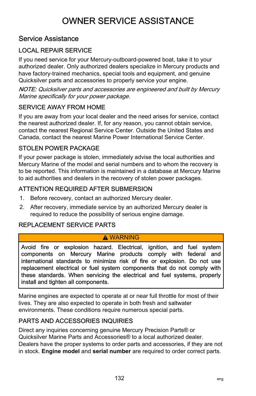
######################## Engine Runs Erratically POSSIBLE CAUSES
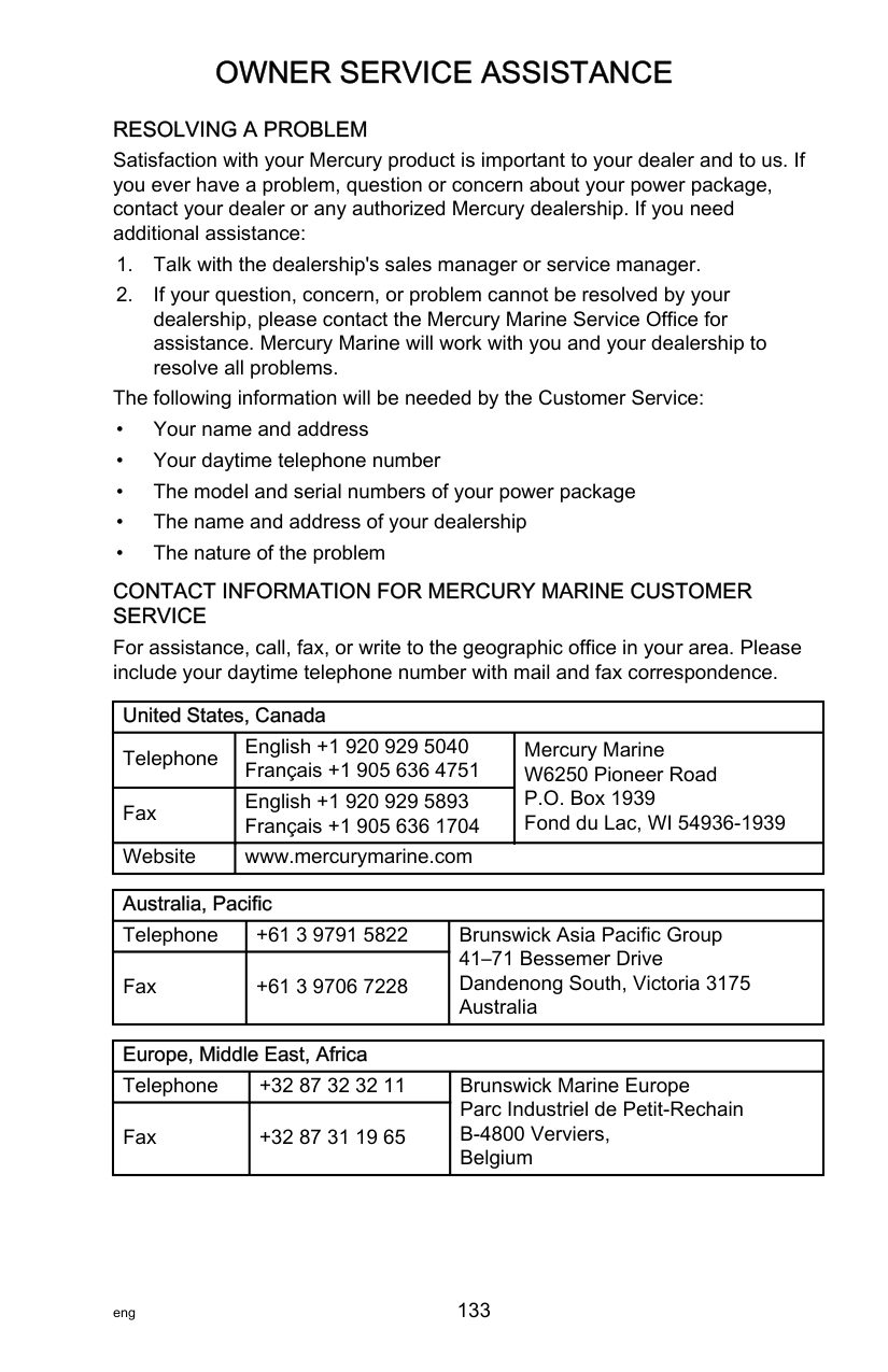
######################## Service Assistance LOCAL REPAIR SERVICE
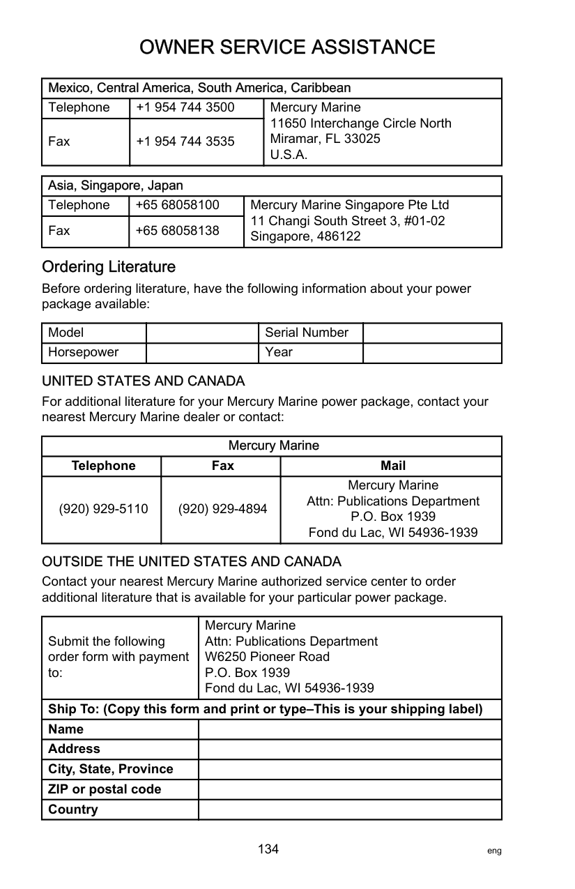
If you need service for your Mercury‑outboard‑powered boat, take it to your authorized dealer. Only authorized dealers specialize in Mercury products and have factory‑trained mechanics, special tools and equipment, and genuine Quicksilver parts and accessories to properly service your engine. NOTE:Quicksilver parts and accessories are engineered and built by Mercury Marine specifically for your power package. SERVICE AWAY FROM HOME
If you are away from your local dealer and the need arises for service, contact the nearest authorized dealer. If, for any reason, you cannot obtain service, contact the nearest Regional Service Center. Outside the United States and Canada, contact the nearest Marine Power International Service Center.
STOLEN POWER PACKAGE If your power package is stolen, immediately advise the local authorities and Mercury Marine of the model and serial numbers and to whom the recovery is to be reported. This information is maintained in a database at Mercury Marine to aid authorities and dealers in the recovery of stolen power packages. ATTENTION REQUIRED AFTER SUBMERSION
required to reduce the possibility of serious engine damage. REPLACEMENT SERVICE PARTS
||!| |---|
WARNING| |---| |Avoid fire or explosion hazard. Electrical, ignition, and fuel system components on Mercury Marine products comply with federal and international standards to minimize risk of fire or explosion. Do not use replacement electrical or fuel system components that do not comply with these standards. When servicing the electrical and fuel systems, properly install and tighten all components.|
Marine engines are expected to operate at or near full throttle for most of their lives. They are also expected to operate in both fresh and saltwater environments. These conditions require numerous special parts.
PARTS AND ACCESSORIES INQUIRIES Direct any inquiries concerning genuine Mercury Precision Parts® or Quicksilver Marine Parts and Accessories® to a local authorized dealer. Dealers have the proper systems to order parts and accessories, if they are not in stock. Engine model and serial number are required to order correct parts.
RESOLVING A PROBLEM Satisfaction with your Mercury product is important to your dealer and to us. If you ever have a problem, question or concern about your power package, contact your dealer or any authorized Mercury dealership. If you need additional assistance:

The following information will be needed by the Customer Service:
########################### CONTACT INFORMATION FOR MERCURY MARINE CUSTOMER SERVICE
For assistance, call, fax, or write to the geographic office in your area. Please include your daytime telephone number with mail and fax correspondence.
|United States, Canada|United States, Canada|United States, Canada| |---|---|---| |Telephone|English +1 920 929 5040 Français +1 905 636 4751|Mercury Marine W6250 Pioneer Road P.O. Box 1939 Fond du Lac, WI 54936-1939| |Fax|English +1 920 929 5893 Français +1 905 636 1704|Mercury Marine W6250 Pioneer Road P.O. Box 1939 Fond du Lac, WI 54936-1939| |Website|www.mercurymarine.com|www.mercurymarine.com|
|Australia, Pacific|Australia, Pacific|Australia, Pacific| |---|---|---| |Telephone|+61 3 9791 5822|Brunswick Asia Pacific Group 41–71 Bessemer Drive Dandenong South, Victoria 3175 Australia|

|Fax|+61 3 9706 7228|Brunswick Asia Pacific Group 41–71 Bessemer Drive Dandenong South, Victoria 3175 Australia|
|Europe, Middle East, Africa|Europe, Middle East, Africa|Europe, Middle East, Africa| |---|---|---| |Telephone|+32 87 32 32 11|Brunswick Marine Europe Parc Industriel de Petit-Rechain B-4800 Verviers, Belgium| |Fax|+32 87 31 19 65|Brunswick Marine Europe Parc Industriel de Petit-Rechain B-4800 Verviers, Belgium|
|Mexico, Central America, South America, Caribbean|Mexico, Central America, South America, Caribbean|Mexico, Central America, South America, Caribbean| |---|---|---| |Telephone|+1 954 744 3500|Mercury Marine 11650 Interchange Circle North Miramar, FL 33025 U.S.A.| |Fax|+1 954 744 3535|Mercury Marine 11650 Interchange Circle North Miramar, FL 33025 U.S.A.|
|Asia, Singapore, Japan|Asia, Singapore, Japan|Asia, Singapore, Japan| |---|---|---| |Telephone|+65 68058100|Mercury Marine Singapore Pte Ltd 11 Changi South Street 3, #01-02 Singapore, 486122| |Fax|+65 68058138|Mercury Marine Singapore Pte Ltd 11 Changi South Street 3, #01-02 Singapore, 486122|
######################## Ordering Literature
Before ordering literature, have the following information about your power package available:
|Model| |Serial Number| | |---|---|---|---| |Horsepower| |Year| |
UNITED STATES AND CANADA For additional literature for your Mercury Marine power package, contact your nearest Mercury Marine dealer or contact:
|Mercury Marine|Mercury Marine|Mercury Marine| |---|---|---| |Telephone|Fax|Mail| |(920) 929‑5110|(920) 929‑4894|Mercury Marine Attn: Publications Department P.O. Box 1939 Fond du Lac, WI 54936-1939|
OUTSIDE THE UNITED STATES AND CANADA Contact your nearest Mercury Marine authorized service center to order additional literature that is available for your particular power package.
|Submit the following order form with payment to:|Mercury Marine Attn: Publications Department W6250 Pioneer Road P.O. Box 1939 Fond du Lac, WI 54936-1939| |---|---| |Ship To: (Copy this form and print or type–This is your shipping label)|Ship To: (Copy this form and print or type–This is your shipping label)| |Name| | |Address| | |City, State, Province| | |ZIP or postal code| | |Country| |
|Quantity|Item|Stock Number|Price|Total| |---|---|---|---|---| | | | |.|.| | | | |.|.| | | | |.|.| | | | |.|.| | | | |.|.| |Total Due|Total Due|Total Due|Total Due|.|
#### MAINTENANCE LOG
######################## Maintenance Log
Record all maintenance performed on your outboard here. Be sure to save all work orders and receipts.
|Date|Maintenance Performed|Engine Hours| |---|---|---| | | | | | | | | | | | | | | | | | | | | | | | | | | | | | | | | | | | | | | | | | | | | | | | | | | | | | | | | | | | | | | | | | | | | | | | | | | | |