Ask AI
— answers from the official manualAnswers from the official manual.
Common questions
Common Questions
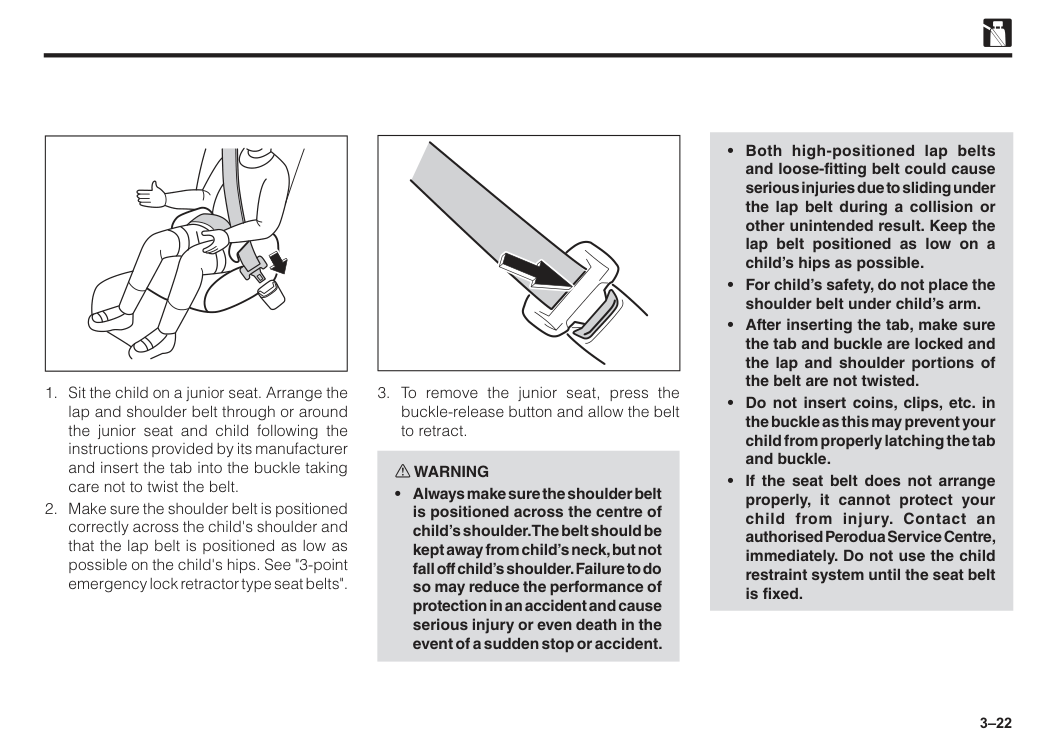
20 totalWhat fuel type should I use in the Perodua Bezza?
Use only unleaded fuel with a Research Octane Number (RON) of 95 or higher. Never use leaded fuel in your Perodua, as it can damage the catalytic converter and emission control system. A fuel information label is also attached on the back of the fuel lid for reference. (Page 15)
What should I do during the break-in period of a new Bezza?
During the first 1,000 km, do not drive over 90 km/h and avoid driving for long periods at any one constant speed. You should also avoid full throttle starts and sudden stops, especially during the first 300 km. Following these precautions helps extend the future performance and economy of your vehicle. (Page 16)
How do I open the fuel filler lid on the Bezza?
Pull up the remote fuel lid lever located on the lower right side of the driver's seat to unlock the fuel lid. To close, simply close the fuel lid from the outside and make sure it is securely locked. Always turn off the engine before refueling and do not smoke or use any flame near the fuel filler. (Page 32)
How do I open and close the fuel lid?
To open: Pull up the remote fuel lid lever located on the lower right side of the driver’s seat. To close, pull down to lock the cap securely (Page 31).
What is the role of SRS airbags in my car and how do they work?
SRS airbags are designed to deploy instantly during severe frontal impacts, providing additional protection when combined with seat belts. They help reduce injury by cushioning impacts to occupants' faces, heads, and chests (Pages 38-40).
What should I avoid while using a rear-facing child restraint system?
Never use a rearward facing child restraint on a seat with an active airbag in front of it, such as the front passenger seat, due to risks of death or serious injury (Page 41).
Show 14 more questions
What should I do if I notice any malfunction in my SRS airbags?
What steps should I take if my vehicle is parked in a garage?
How do I properly install a child restraint system?
What are the hazards of leaving children or pets in a parked car?
How do I adjust my seat to avoid potential safety issues?
How do I initialize the Window Jam Pro (auto-reverse) feature on the driver's window?
What should I do if I lose my smart key?
How do I open and lock doors with smart entry?
What does it mean if the SRS airbag warning light stays on after starting the car?
How do I use the smart entry system to lock and unlock the Bezza?
How long does the transmitter (key fob) battery last, and how do I know when to replace it?
What are the engine options available for the Perodua Bezza?
Is it safe to install a rear-facing child seat in the front passenger seat of the Bezza?
What should I do if I suspect exhaust fumes are entering the cabin while driving?
Full Manual
291 pages

We are pleased to welcome you to the family of Perodua owners. As you know, the performance and durability of a vehicle depends, to a large extent, upon the way it is maintained and driven. This manual will assist you to benefit most from your Perodua vehicle. Before you operate your vehicle, read this manual carefully and use it as a reference source whenever necessary. If you have any questions, feel free to contact your authorised Perodua Service Centre. We are ready to provide qualified service and assistance.
Perodua Sales Sdn. Bhd.
©2020 Perodua Sales Sdn. Bhd.
All rights reserved. This material may not be produced or copied, in whole or in part, without the written permission of Perodua Sales Sdn Bhd. Foreword
The information in this manual is subject to change without notice. No part of this manual may be reproduced or transmitted in any form or by any means electronic or mechanical including photocopying, recording or information storage and retrieval systems for any purpose other than personal use without our written permission. While every effort has been made to ensure that the information and contents in the manual are complete, accurate, up-to-date, reliable and non-misleading, we cannot be held responsible for mistakes, inaccurancies, or errors found in the manual. Nor is any liability assumed for damages resulting from the reliance and use of information contained herein. This manual is provided without any representation or warranties, express or implied.
Perodua Sales Sdn. Bhd.
Disclaimer
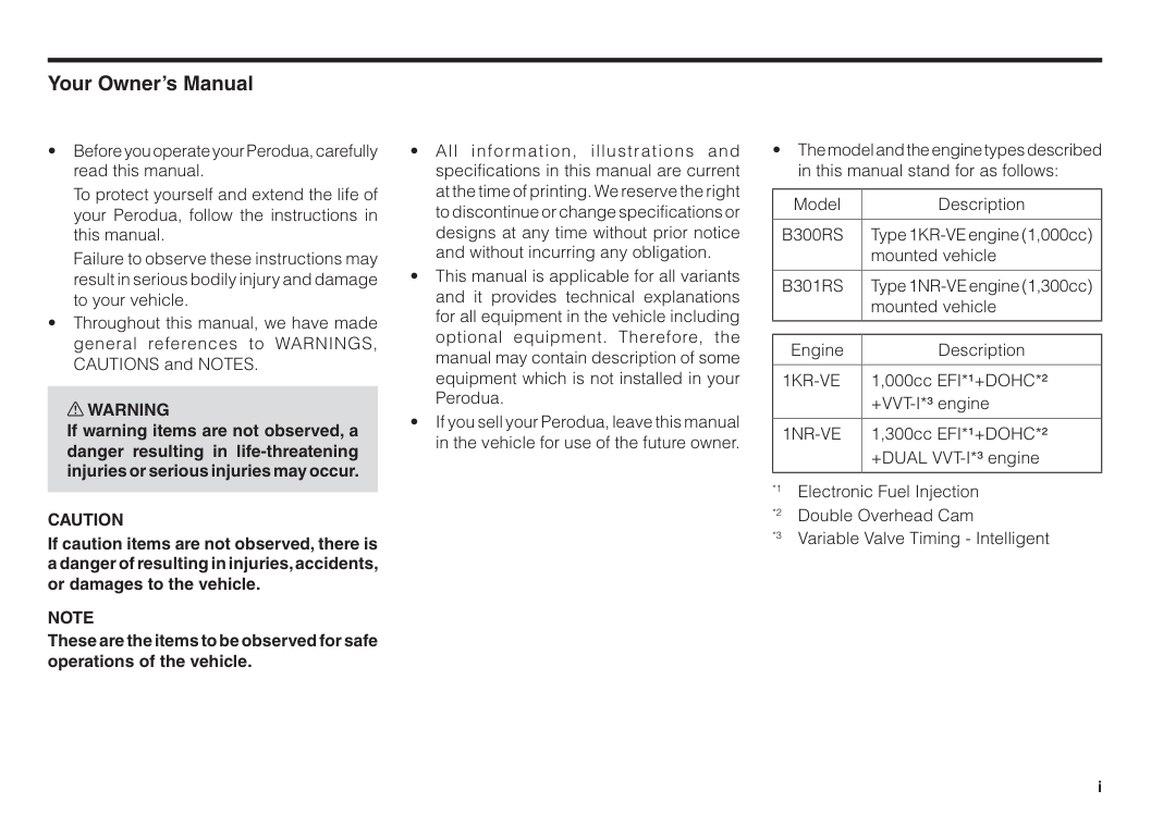
To protect yourself and extend the life of your Perodua, follow the instructions in this manual.
Failure to observe these instructions may result in serious bodily injury and damage to your vehicle.
Caution
If caution items are not observed, there is a danger of resulting in injuries, accidents, or damages to the vehicle.Note
These are the items to be observed for safe operations of the vehicle.B300Rs
Type 1KR-VE engine (1,000cc) mounted vehicleB301Rs
Type 1NR-VE engine (1,300cc) mounted vehicle Engine Description1Kr-Ve
1,000cc EFI*1+DOHC*2 +VVT-I*3 engine1Nr-Ve
1,300cc EFI*1+DOHC*2 +DUAL VVT-I*3 engine *1 Electronic Fuel Injection *2 Double Overhead Cam *3 Variable Valve Timing - Intelligent i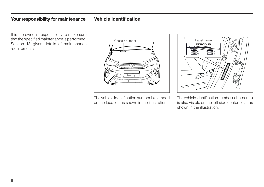
Your responsibility for maintenance It is the owner’s responsibility to make sure that the specified maintenance is performed. Section 13 gives details of maintenance requirements. Vehicle identification Chassis number Label name
Vta No.
kg kg kg kg 1 - 2 -V I N
The vehicle identification number is stamped on the location as shown in the illustration. The vehicle identification number (label name) is also visible on the left side center pillar as shown in the illustration. ii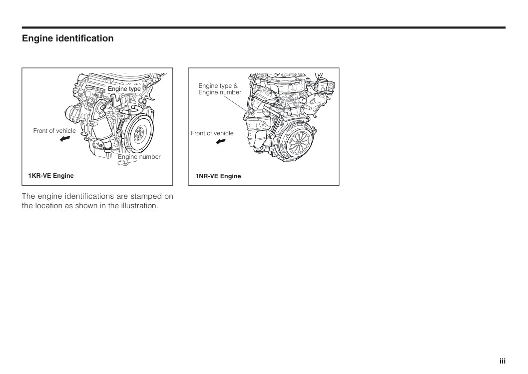
Engine identification The engine identifications are stamped on the location as shown in the illustration. Front of vehicle 1NR-VE Engine Engine type & Engine number Engine type Engine number Front of vehicle 1KR-VE Engine iii
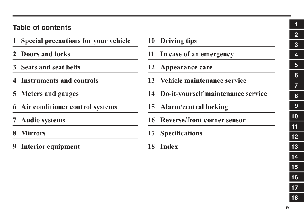
Table of contents 1 Special precautions for your vehicle 2 Doors and locks 3 Seats and seat belts 4 Instruments and controls 5 Meters and gauges 6 Air conditioner control systems 7 Audio systems 8 Mirrors 9 Interior equipment 10 Driving tips 11 In case of an emergency 12 Appearance care 13 Vehicle maintenance service 14 Do-it-yourself maintenance service 15 Alarm/central locking 16 Reverse/front corner sensor 17 Specifications 18 Index iv 1 2 3 4 5 6 7 8 9 10 11 12 13 14 15 16 17 18
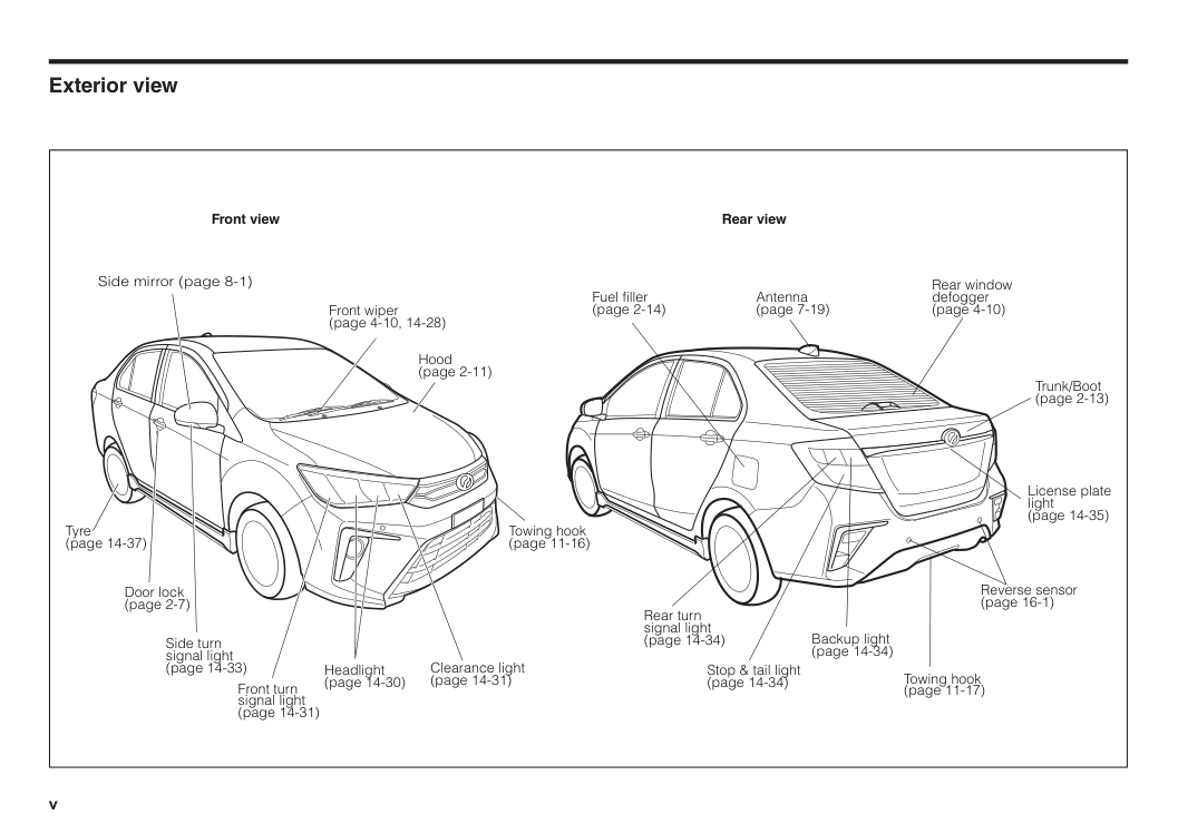
Exterior view v Front view Side mirror (page 8-1) Front wiper (page 4-10, 14-28) Hood (page 2-11) Towing hook (page 11-16) Headlight (page 14-30) Front turn signal light (page 14-31) Tyre (page 14-37) Door lock (page 2-7) Side turn signal light (page 14-33) Clearance light (page 14-31) Rear view Trunk/Boot (page 2-13) License plate light (page 14-35) Backup light (page 14-34) Antenna (page 7-19) Fuel filler (page 2-14) Rear window defogger (page 4-10) Rear turn signal light (page 14-34) Stop & tail light (page 14-34) Reverse sensor (page 16-1) Towing hook (page 11-17)
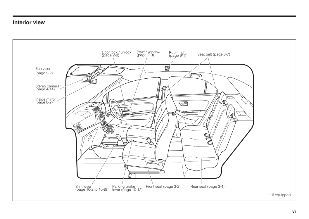
Interior view vi Power window (page 2-9) Door lock / unlock (page 2-8) Room light (page 9-1) Inside mirror (page 8-2) Sun visor (page 9-2) Seat belt (page 3-7) Parking brake lever (page 10-12) Front seat (page 3-2) Rear seat (page 3-4) Shift lever (page 10-2 to 10-8)
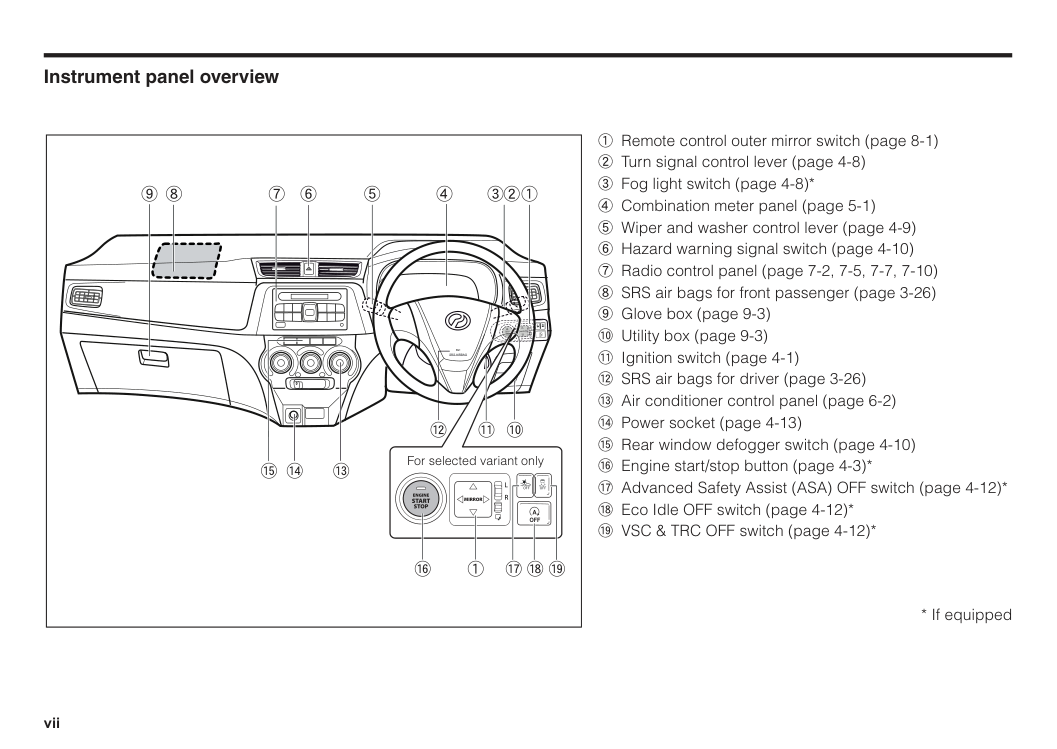
Instrument panel overview 1 Remote control outer mirror switch (page 8-1) 2 Turn signal control lever (page 4-8) 3 Fog light switch (page 4-8)* 4 Combination meter panel (page 5-1) 5 Wiper and washer control lever (page 4-9) 6 Hazard warning signal switch (page 4-10) 7 Radio control panel (page 7-2, 7-5, 7-7, 7-10) 8 SRS air bags for front passenger (page 3-26) 9 Glove box (page 9-3) ! Utility box (page 9-3) " Ignition switch (page 4-1) # SRS air bags for driver (page 3-26) $ Air conditioner control panel (page 6-2) % Power socket (page 4-13) & Rear window defogger switch (page 4-10) ' Engine start/stop button (page 4-3)* ( Advanced Safety Assist (ASA) OFF switch (page 4-12)* ) Eco Idle OFF switch (page 4-12)*
Srs Airbag
R
L
Mirror
Engine
Start
Stop
& 9 8 7 6 5 4 321 # " ! % $ ( ) * For selected variant onlyOff
Off
Off
A
R
L
Off
Off
Off
A
' 1
1 Engine exhaust gas..........................................................................1–1 Catalytic converter...........................................................................1–2 For your safety..................................................................................1–3 Bring your children and keys with you whenever you leave the car......................................................1–4 Fuel recommendation......................................................................1–4 Modification of your vehicle............................................................1–4 Installation / use of electronic items in your vehicle.....................1–5 Break-in period.................................................................................1–5 Section 1 Special precautions for your vehicle
1–1 Engine exhaust gas w WARNING Do not inhale exhaust gases. They contain carbon monoxide, a poisonous gas that is colourless and odourless. Inhalation of this gas can cause unconsciousness or even death. Whenever you suspect that exhaust fumes may have entered the vehicle, find out the cause. Have the condition corrected immediately. If you must drive your vehicle under this condition, drive with all side windows fully open. To prevent exhaust gas accident, follow the precautions below. Maintenance; Always maintain the engine exhaust system, vehicle body, and ventilation system in their correct operating conditions. Make sure the exhaust system has no loose connections or holes. We recommend that the exhaust system and vehicle body be inspected by competent repair facilities in the following cases:
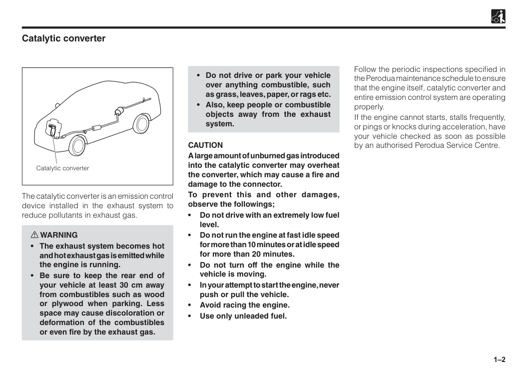
1–2 Catalytic converter The catalytic converter is an emission control device installed in the exhaust system to reduce pollutants in exhaust gas. w WARNING
Caution
A large amount of unburned gas introduced into the catalytic converter may overheat the converter, which may cause a fire and damage to the connector. To prevent this and other damages, observe the followings; • Do not drive with an extremely low fuel level. • Do not run the engine at fast idle speed for more than 10 minutes or at idle speed for more than 20 minutes. • Do not turn off the engine while the vehicle is moving. • In your attempt to start the engine, never push or pull the vehicle. • Avoid racing the engine. • Use only unleaded fuel. Follow the periodic inspections specified in the Perodua maintenance schedule to ensure that the engine itself, catalytic converter and entire emission control system are operating properly. If the engine cannot starts, stalls frequently, or pings or knocks during acceleration, have your vehicle checked as soon as possible by an authorised Perodua Service Centre. Catalytic converter
1–3 For your safety Remember that while you rely on the manufacturer to make a good vehicle, the manufacturer and the motoring public rely on you to drive safely. We at Perodua want you to enjoy your new vehicle with all its capabilities. We also hope that you could consider your safety while driving which includes in learning about the capabilities and limitations of a vehicle, and realizing that vehicles designed for different purposes may handle differently. Read and understand all WARNINGS, CAUTIONS and NOTES in this manual. w WARNING
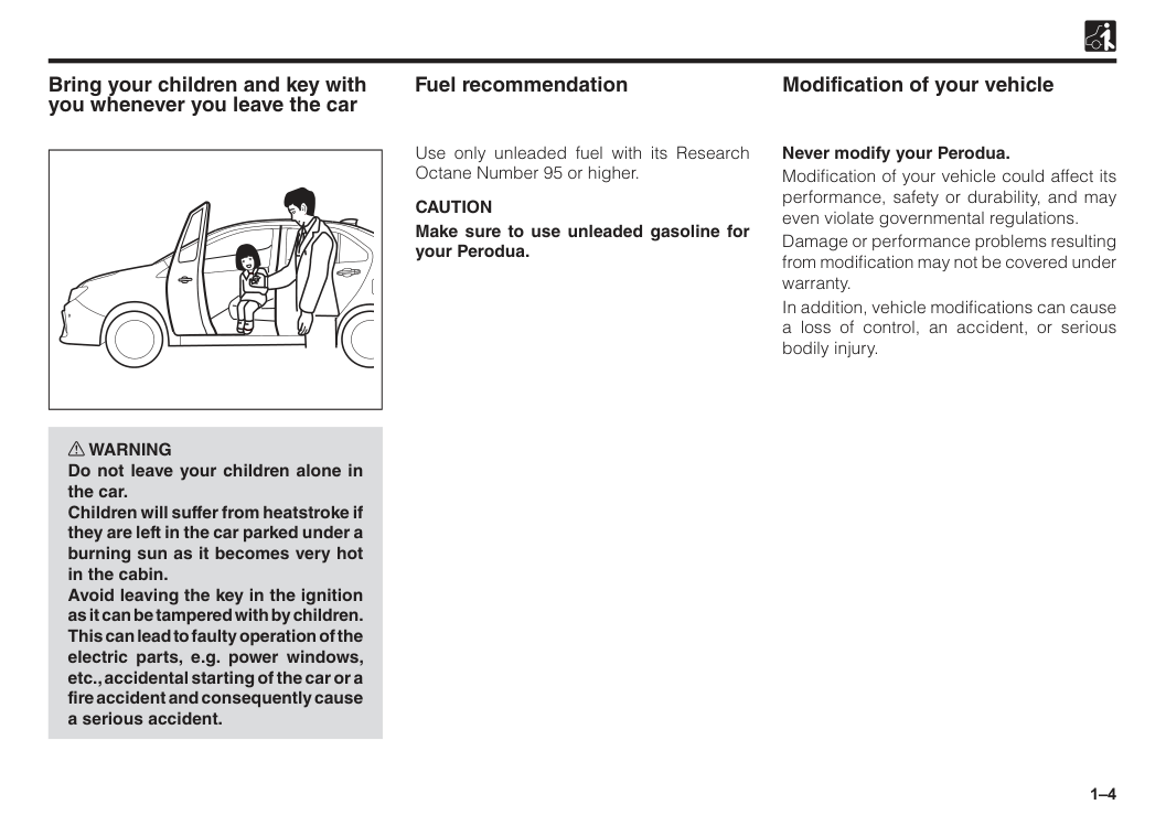
1–4 Bring your children and key with you whenever you leave the car w WARNING Do not leave your children alone in the car. Children will suffer from heatstroke if they are left in the car parked under a burning sun as it becomes very hot in the cabin. Avoid leaving the key in the ignition as it can be tampered with by children. This can lead to faulty operation of the electric parts, e.g. power windows, etc., accidental starting of the car or a fire accident and consequently cause a serious accident. Modification of your vehicle Fuel recommendation Use only unleaded fuel with its Research Octane Number 95 or higher.
Caution
Make sure to use unleaded gasoline for your Perodua. Never modify your Perodua. Modification of your vehicle could affect its performance, safety or durability, and may even violate governmental regulations. Damage or performance problems resulting from modification may not be covered under warranty. In addition, vehicle modifications can cause a loss of control, an accident, or serious bodily injury.
1–5 Installation / use of electronic items in your vehicle When any electronic item which will likely to generate a strong electromagnetic wave, such as a two-way radio system, mobile telephone and computer, is installed and used in your vehicle, be sure to consult with an authorised Perodua Service Centre. The electromagnetic wave generated from these pieces of electronic equipment could affect adversely those systems, such as the EFI (Electronic Fuel Injection) system, ABS (Anti-lock Braking System) and SRS air bags of your vehicle, resulting in improper operation. Accessories, spare parts and modification of your Perodua. A wide variety of non−genuine spare parts and accessories for Perodua vehicles are currently available in the market. Using these spare parts and accessories which are not genuine Perodua products may adversely affect the safety of your vehicle. Perodua therefore cannot accept any liability or guarantee spare parts and accessories which are not genuine Perodua products, nor for replacement or installation involving such parts. This vehicle should not be modified with non−genuine Perodua products. Modification with non−genuine Perodua products could affect its performance, safety or durability, and may even violate governmental regulations. In addition, damage or performance problems resulting from the modification may not be covered under warranty. Break-in period The internal friction, which is high in a new vehicle, will decrease gradually as all moving parts adjust to each other. We recommend observing the following precautions during the first 1,000 km to extend the future performance and economy of your vehicle.
2 Section 2 Doors and locks Engine immobilizer system.............................................................2–1 Keys (with engine immobilizer system)..........................................2–1 Smart entry (if equipped).................................................................2–2 Warning buzzer (if equipped)..........................................................2–5 Remote keyless entry / transmitter.................................................2–5 Door locks.........................................................................................2–7 Child safety lock...............................................................................2–8 Power windows.................................................................................2–9 Hood..................................................................................................2–11 Trunk / Boot.......................................................................................2–13 Fuel filler............................................................................................2–14
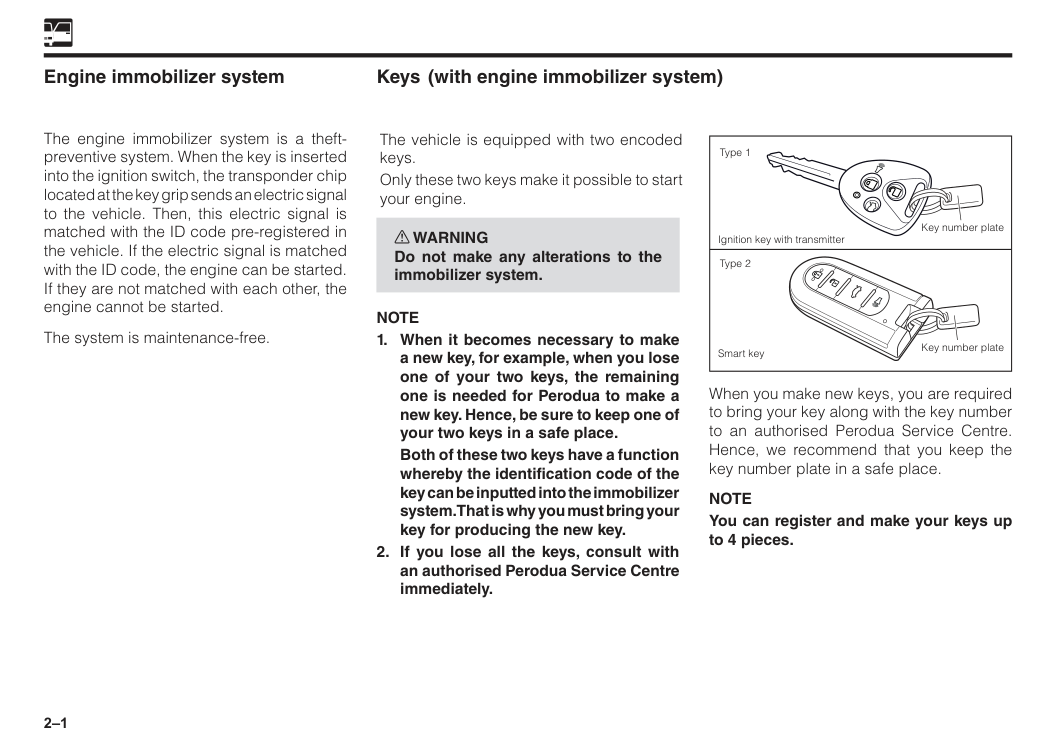
2–1 Engine immobilizer system The engine immobilizer system is a theft- preventive system. When the key is inserted into the ignition switch, the transponder chip located at the key grip sends an electric signal to the vehicle. Then, this electric signal is matched with the ID code pre-registered in the vehicle. If the electric signal is matched with the ID code, the engine can be started. If they are not matched with each other, the engine cannot be started. The system is maintenance-free. When you make new keys, you are required to bring your key along with the key number to an authorised Perodua Service Centre. Hence, we recommend that you keep the key number plate in a safe place.
Note
You can register and make your keys up to 4 pieces. Key number plate Key number plate Type 1 Type 2 Ignition key with transmitter Smart key Keys The vehicle is equipped with two encoded keys. Only these two keys make it possible to start your engine. w WARNING Do not make any alterations to the immobilizer system.Note
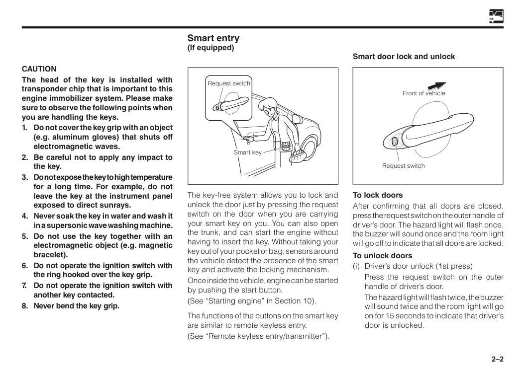
2–2
Caution
The head of the key is installed with transponder chip that is important to this engine immobilizer system. Please make sure to observe the following points when you are handling the keys.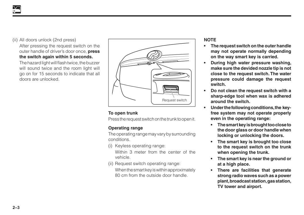
2–3 (ii) All doors unlock (2nd press)
After pressing the request switch on the outer handle of driver’s door once, press the switch again within 5 seconds.
The hazard light will flash twice, the buzzer will sound twice and the room light will go on for 15 seconds to indicate that all doors are unlocked. To open trunk Press the request switch on the trunk to open it. Operating range The operating range may vary by surrounding conditions. (i) Keyless operating range:
Within 3 meter from the center of the vehicle. (ii) Request switch operating range:
When the smart key is within approximately 80 cm from the outside door handle.
Note
• The request switch on the outer handle may not operate normally depending on the way smart key is carried. • During high water pressure washing, make sure the devided nozzle tip is not close to the request switch. The water pressure could damage the request switch. • Do not clean the request switch with a sharp-edge tool when wax is adhered around the switch. • Under the following conditions, the key- free system may not operate properly even in the operating range: • The smart key is brought too close to the door glass or door handle when locking or unlocking the doors. • The smart key is brought too close to the request switch on the trunk when opening the trunk. • The smart key is near the ground or at a high place. • There are facilities that generate strong radio waves such as a power plant, broadcast station, gas station, TV tower and airport. Request switch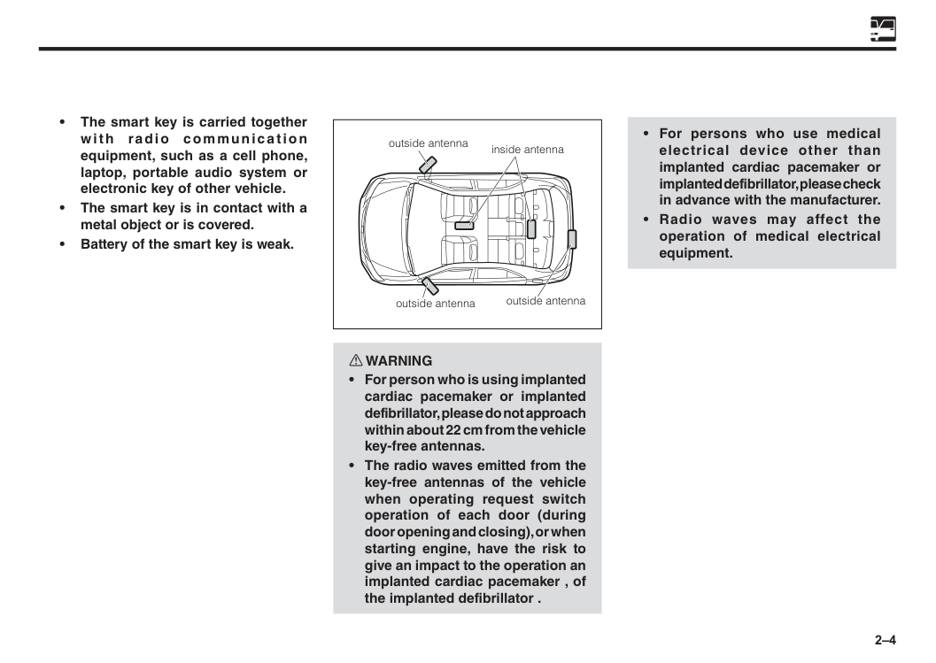
2–4 inside antenna outside antenna outside antenna outside antenna • The smart key is carried together with radio communication equipment, such as a cell phone, laptop, portable audio system or electronic key of other vehicle. • The smart key is in contact with a metal object or is covered. • Battery of the smart key is weak. w WARNING
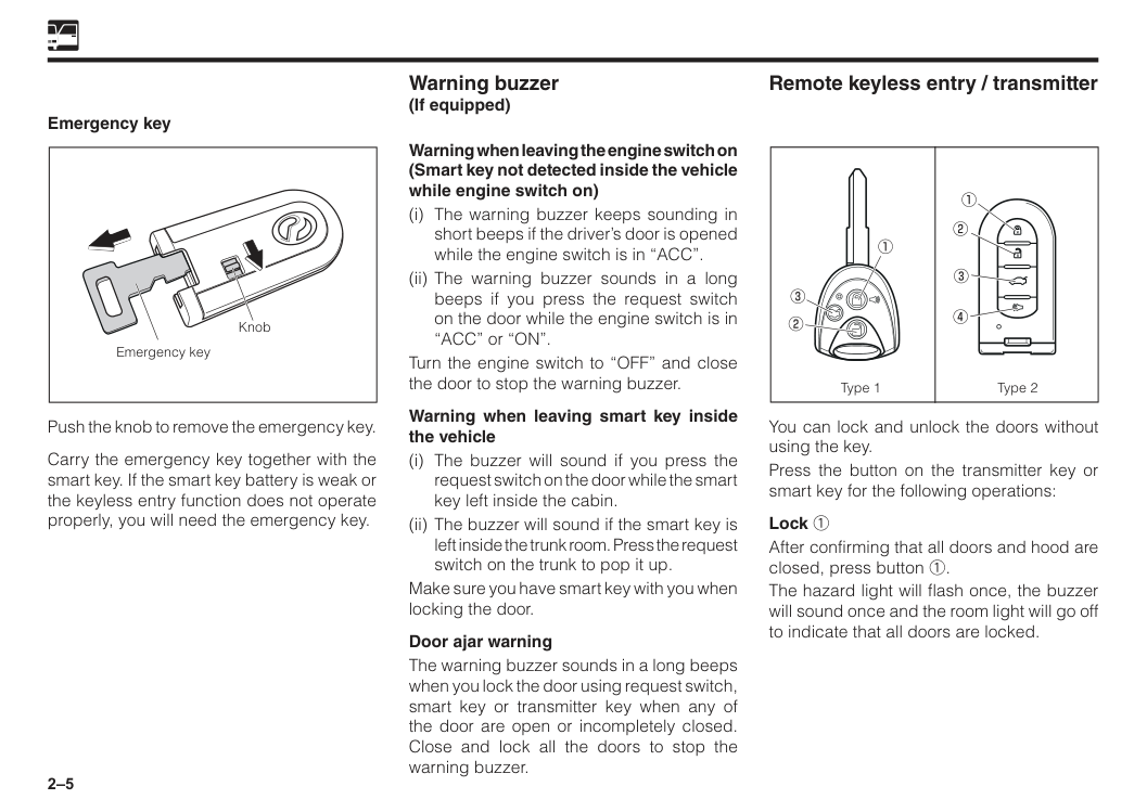
2–5 Remote keyless entry / transmitter Warning buzzer (If equipped) You can lock and unlock the doors without using the key. Press the button on the transmitter key or smart key for the following operations: Lock 1 After confirming that all doors and hood are closed, press button 1. The hazard light will flash once, the buzzer will sound once and the room light will go off to indicate that all doors are locked. Push the knob to remove the emergency key. Carry the emergency key together with the smart key. If the smart key battery is weak or the keyless entry function does not operate properly, you will need the emergency key. Warning when leaving the engine switch on (Smart key not detected inside the vehicle while engine switch on) (i) The warning buzzer keeps sounding in short beeps if the driver’s door is opened while the engine switch is in “ACC”. (ii) The warning buzzer sounds in a long beeps if you press the request switch on the door while the engine switch is in “ACC” or “ON”. Turn the engine switch to “OFF” and close the door to stop the warning buzzer. Warning when leaving smart key inside the vehicle (i) The buzzer will sound if you press the request switch on the door while the smart key left inside the cabin. (ii) The buzzer will sound if the smart key is left inside the trunk room. Press the request switch on the trunk to pop it up. Make sure you have smart key with you when locking the door. Door ajar warning The warning buzzer sounds in a long beeps when you lock the door using request switch, smart key or transmitter key when any of the door are open or incompletely closed. Close and lock all the doors to stop the warning buzzer. Type 1 Type 2 Emergency key Knob Emergency key
2–6 Unlock 2 (i) Driver’s door unlock (1st press)
Press button 2 once.
The hazard light will flash twice, the buzzer will sound twice and the room light will go on for 15 seconds to indicate that driver’s door is unlocked. (ii) All doors unlock (2nd press)
After pressing button 2 once, press the button again within 5 seconds.
The hazard light will flash twice, the buzzer will sound twice and the room light will go on for 15 seconds to indicate that all doors are unlocked.
If the door remains closed for approximate 30 seconds after unlocking, all the doors are locked automatically. Trunk open 3 Press button 3 for more than 1 second to open the trunk. Buzzer will sound. Panic button 4 (If equipped) When button 4 of type 2 is pressed for more than 1 second, or button 1 of type 1 is pressed for more than 3 seconds, horn will sound, room light will turn on, hazard light will flash and security indicator will turn on.To stop, press button 1, 2 or 4. Horn will sound for 45 seconds if no button 1, 2 or 4 is pressed.
Caution
2–7 Security alarm control Set/unset the alarm by the transmitter. The alarm starts when any of the doors or hood are opened without unlocking the door by the keyless unit. Alarm: Horn sounds and hazard light flashes for 30 seconds. Horn and hazard light will be off after 30 seconds. To deactivate alarm • All doors including hood and trunk must be closed or
(See “Car alarm/central lock” in Section 15). Replacement of battery The button battery incorporated inside has a lifetime of approximately 2 years on the assumption that the locking / unlocking operations are made 10 times a day. (However, in the case of a new-car, the lifetime of the transmitter battery may be shorter.) When the operation becomes unstable or the operation becomes no longer possible, most likely the battery has been consumed. Replace the battery or please consult with an authorised Perodua Service Centre. (See “Warning lights” in Section 5). (See “Replacement of battery in the transmitter” in Section 15). Door locks w WARNING
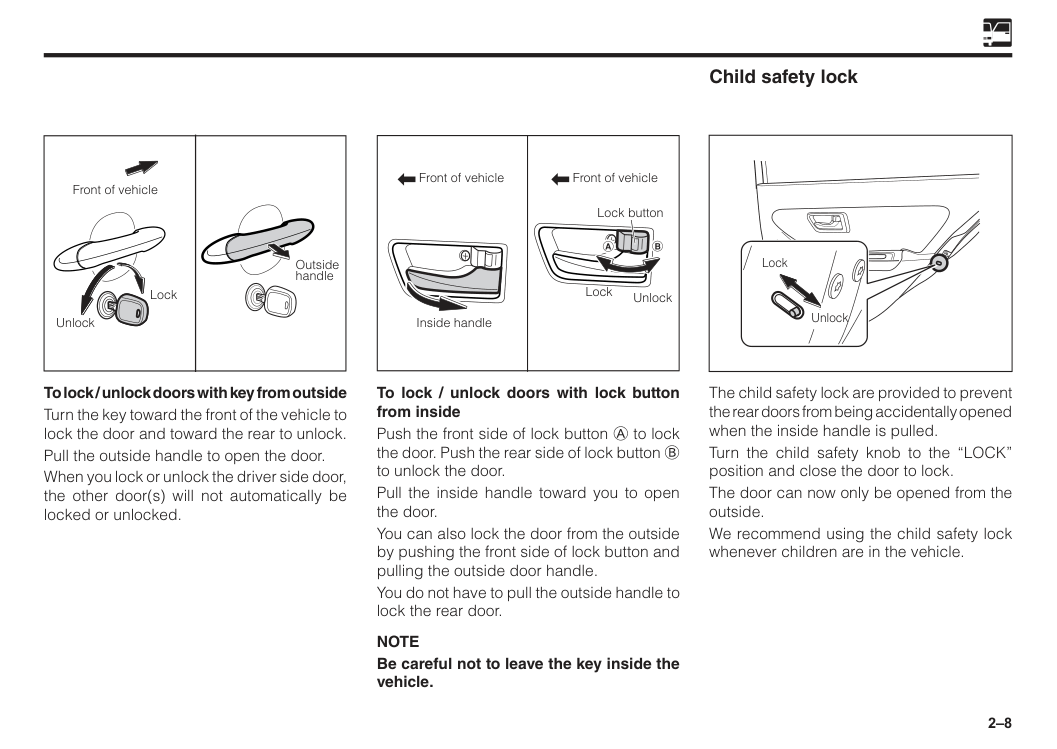
2–8 Front of vehicle Front of vehicle Lock Unlock Inside handle Lock button To lock / unlock doors with lock button from inside Push the front side of lock button A to lock the door. Push the rear side of lock button B to unlock the door. Pull the inside handle toward you to open the door. You can also lock the door from the outside by pushing the front side of lock button and pulling the outside door handle. You do not have to pull the outside handle to lock the rear door.
Note
Be careful not to leave the key inside the vehicle. Child safety lock Lock Unlock The child safety lock are provided to prevent the rear doors from being accidentally opened when the inside handle is pulled. Turn the child safety knob to the “LOCK” position and close the door to lock. The door can now only be opened from the outside. We recommend using the child safety lock whenever children are in the vehicle. Front of vehicle Unlock Lock Outside handle To lock / unlock doors with key from outside Turn the key toward the front of the vehicle to lock the door and toward the rear to unlock. Pull the outside handle to open the door. When you lock or unlock the driver side door, the other door(s) will not automatically be locked or unlocked.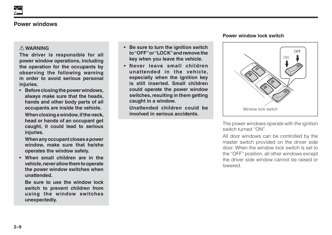
2–9 Power windows w WARNING The driver is responsible for all power window operations, including the operation for the occupants by observing the following warning in order to avoid serious personal injuries.
When closing a window, if the neck, head or hands of an occupant get caught, it could lead to serious injuries.
When any occupant closes a power window, make sure that he/she operates the window safely.
Be sure to use the window lock switch to prevent children from using the window switches unexpectedly.
Unattended children could be involved in serious accidents. Power window lock switch Window lock switch
On
Off
Off
The power windows operate with the ignition switch turned “ON”. All door windows can be controlled by the master switch provided on the driver side door. When the window lock switch is set to the “OFF” position, all other windows except the driver side window cannot be raised or lowered.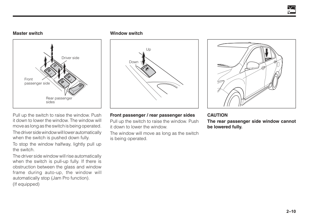
2–10 Rear passenger sides Driver side Front passenger side Master switch Pull up the switch to raise the window. Push it down to lower the window. The window will move as long as the switch is being operated. The driver side window will lower automatically when the switch is pushed down fully. To stop the window halfway, lightly pull up the switch. The driver side window will rise automatically when the switch is pull-up fully. If there is obstruction between the glass and window frame during auto-up, the window will automatically stop (Jam Pro function). (If equipped) Up Down Window switch Front passenger / rear passenger sides Pull up the switch to raise the window. Push it down to lower the window. The window will move as long as the switch is being operated.
Caution
The rear passenger side window cannot be lowered fully.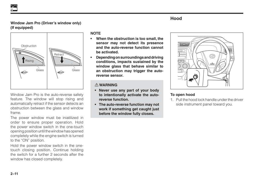
2–11 Window Jam Pro (Driver’s window only) (If equipped) Window Jam Pro is the auto-reverse safety feature. The window will stop rising and automatically retract if the sensor detects an obstruction between the glass and window frame. The power window must be iniatilized in order to ensure proper operation. Hold the power window switch in the one-touch opening position until the window has opened completely while the engine switch is turned to the “ON” position. Hold the power window switch in the one- touch closing position. Continue holding the switch for a further 2 seconds after the window has closed completely. k k Obstruction Glass Retract Glass Rising Hood To open hood
Note
• When the obstruction is too small, the sensor may not detect its presence and the auto-reverse function cannot be activated. • Depending on surroundings and driving conditions, impacts sustained by the window glass that behave similar to an obstruction may trigger the auto- reverse sensor. w WARNING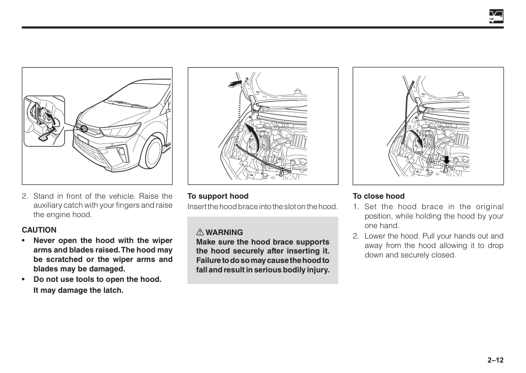
2–12 To support hood Insert the hood brace into the slot on the hood. w WARNING Make sure the hood brace supports the hood securely after inserting it. Failure to do so may cause the hood to fall and result in serious bodily injury. To close hood
Caution
• Never open the hood with the wiper arms and blades raised. The hood may be scratched or the wiper arms and blades may be damaged. • Do not use tools to open the hood.It may damage the latch.
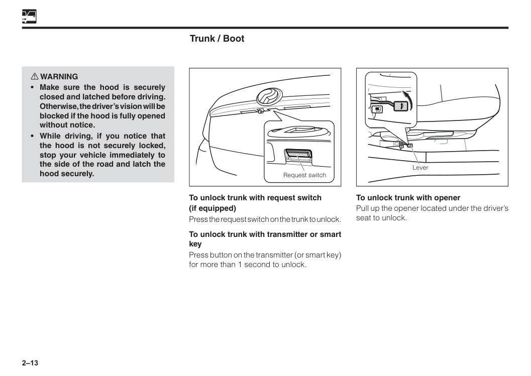
2–13 Trunk / Boot To unlock trunk with request switch (if equipped) Press the request switch on the trunk to unlock. To unlock trunk with transmitter or smart key Press button on the transmitter (or smart key) for more than 1 second to unlock. Request switch Lever To unlock trunk with opener Pull up the opener located under the driver’s seat to unlock. w WARNING
2–14
Note
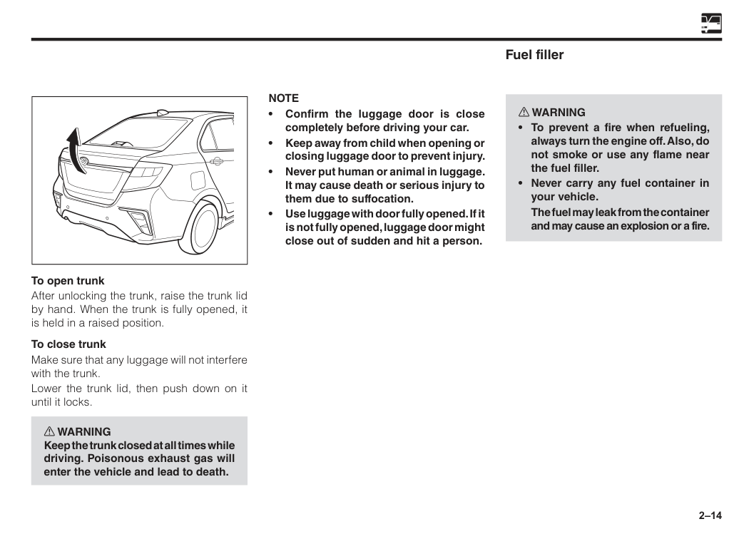
• Confirm the luggage door is close completely before driving your car. • Keep away from child when opening or closing luggage door to prevent injury. • Never put human or animal in luggage. It may cause death or serious injury to them due to suffocation. • Use luggage with door fully opened. If it is not fully opened, luggage door might close out of sudden and hit a person. To open trunk After unlocking the trunk, raise the trunk lid by hand. When the trunk is fully opened, it is held in a raised position. To close trunk Make sure that any luggage will not interfere with the trunk. Lower the trunk lid, then push down on it until it locks. w WARNING Keep the trunk closed at all times while driving. Poisonous exhaust gas will enter the vehicle and lead to death. Fuel filler w WARNINGThe fuel may leak from the container and may cause an explosion or a fire.
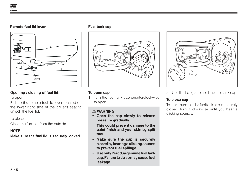
2–15 Remote fuel lid lever Lever Opening / closing of fuel lid: To open: Pull up the remote fuel lid lever located on the lower right side of the driver’s seat to unlock the fuel lid. To close: Close the fuel lid, from the outside.
Note
Make sure the fuel lid is securely locked. Fuel tank capUnleaded
Fuel Only
Close Open To open capThis could prevent damage to the paint finish and your skin by spilt fuel.
Unleaded
Fuel Only
2–16
Caution
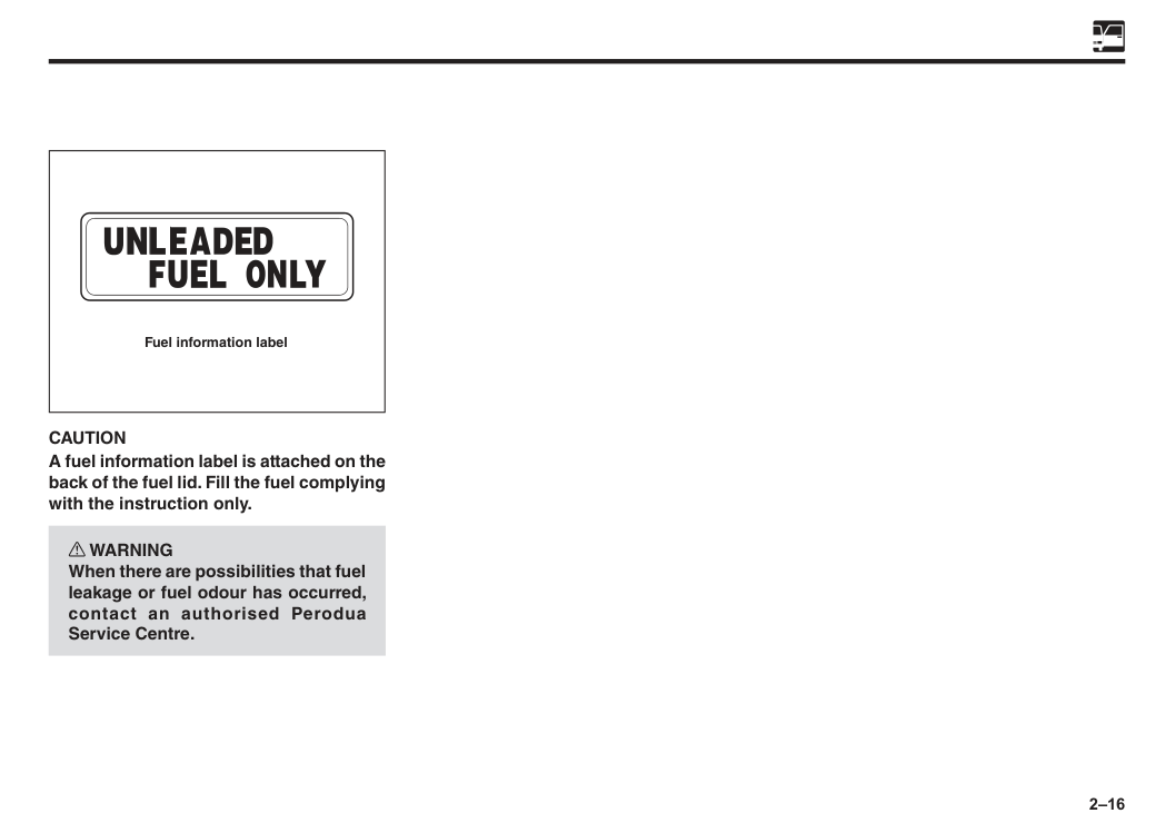
A fuel information label is attached on the back of the fuel lid. Fill the fuel complying with the instruction only. w WARNING When there are possibilities that fuel leakage or fuel odour has occurred, contact an authorised Perodua Service Centre. Fuel information label
3 Seats..................................................................................................3–1 Front seats........................................................................................3–2 Rear seats.........................................................................................3–4 Head restraint...................................................................................3–5 Instructions on seat belts................................................................3–7 3-point emergency lock retractor type seat belts (ELR) ..............3–9 Seat belt warning light and buzzer.................................................3–10 Front seat belt pretensioner............................................................3–10 Child Restraint System....................................................................3–12 SRS (Supplement Restraint System) air bags for driver and front passenger........................................................3–26 SRS air bag.......................................................................................3–30 Vehicle data recordings...................................................................3–40 Event data recorder..........................................................................3–40 Section 3 Seats and seat belts
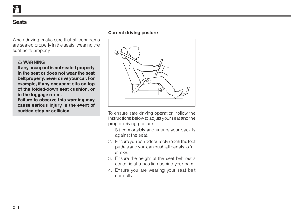
3–1 Seats When driving, make sure that all occupants are seated properly in the seats, wearing the seat belts properly. w WARNING If any occupant is not seated properly in the seat or does not wear the seat belt properly, never drive your car. For example, if any occupant sits on top of the folded-down seat cushion, or in the luggage room. Failure to observe this warning may cause serious injury in the event of sudden stop or collision. 3 2 1 4 To ensure safe driving operation, follow the instructions below to adjust your seat and the proper driving posture:
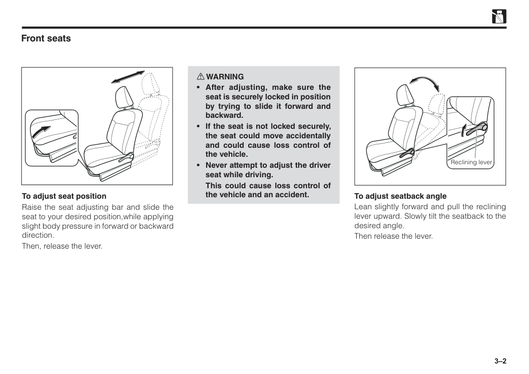
3–2 Front seats To adjust seat position Raise the seat adjusting bar and slide the seat to your desired position,while applying slight body pressure in forward or backward direction. Then, release the lever. To adjust seatback angle Lean slightly forward and pull the reclining lever upward. Slowly tilt the seatback to the desired angle. Then release the lever. Reclining lever w WARNING
This could cause loss control of the vehicle and an accident.
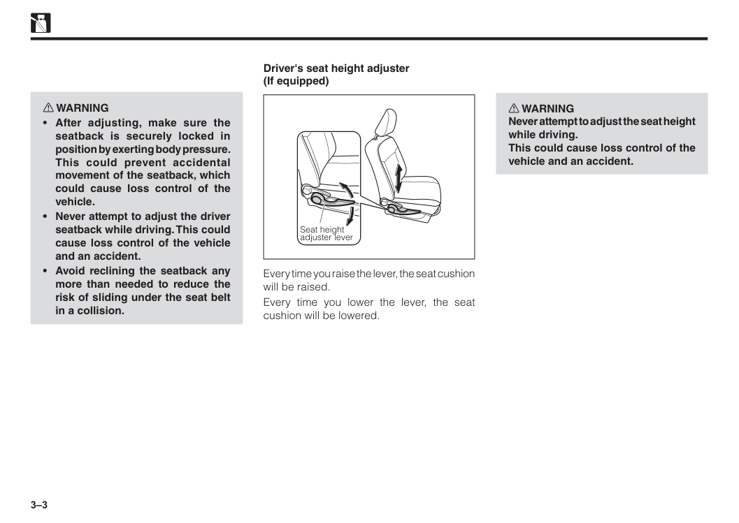
3–3 Seat height adjuster lever Driver's seat height adjuster (If equipped) Every time you raise the lever, the seat cushion will be raised. Every time you lower the lever, the seat cushion will be lowered. w WARNING Never attempt to adjust the seat height while driving. This could cause loss control of the vehicle and an accident. w WARNING
3–4
Caution
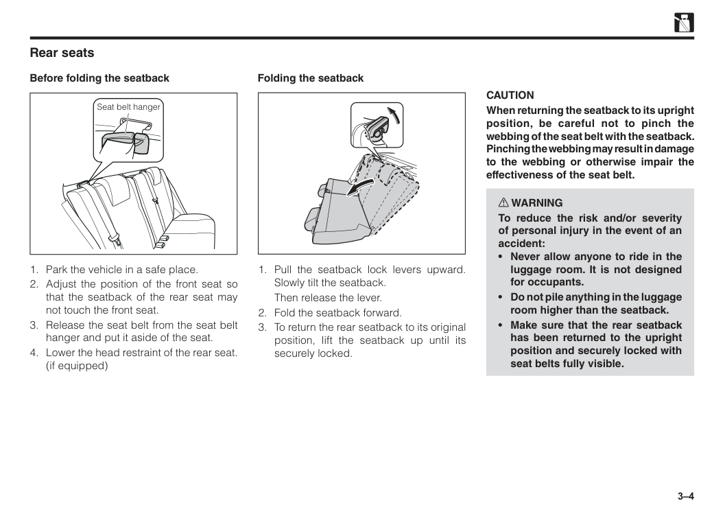
When returning the seatback to its upright position, be careful not to pinch the webbing of the seat belt with the seatback. Pinching the webbing may result in damage to the webbing or otherwise impair the effectiveness of the seat belt. w WARNING To reduce the risk and/or severity of personal injury in the event of an accident:Then release the lever.
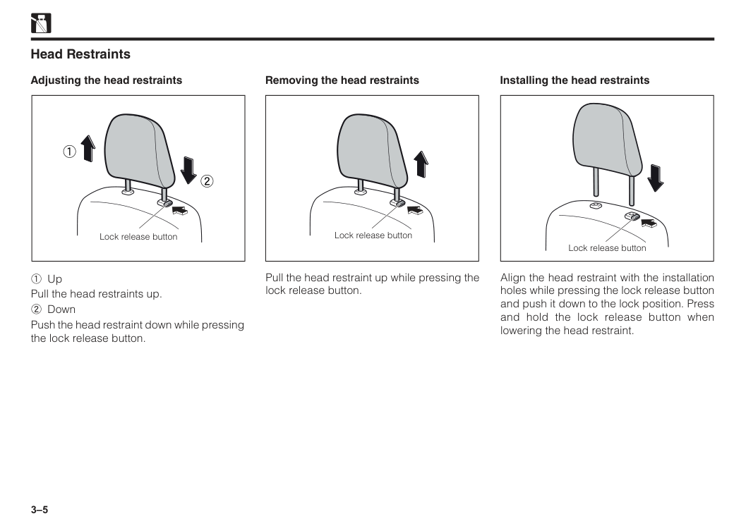
3–5 Removing the head restraints Installing the head restraints 1 Up Pull the head restraints up. 2 Down Push the head restraint down while pressing the lock release button. Pull the head restraint up while pressing the lock release button. Align the head restraint with the installation holes while pressing the lock release button and push it down to the lock position. Press and hold the lock release button when lowering the head restraint. Lock release button 1 2 Lock release button Lock release button Head Restraints Adjusting the head restraints
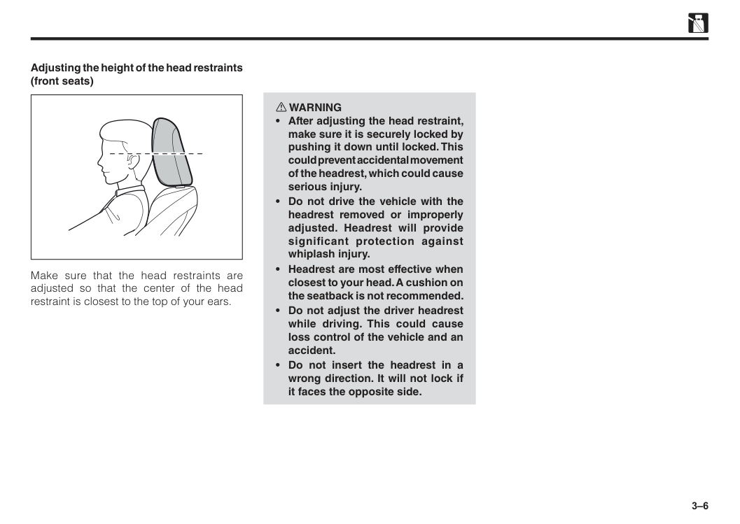
3–6 w WARNING
3–7 Instructions on seat belts All occupants must be properly restrained with a seat belt provided at all times. Observe the following precautions for proper function of the seat belt. Failure to do so could result in serious bodily injury in an accident or sudden braking. The seat belts provided are designed for people of adult size, large enough to properly wear them. Check the belt system periodically and if any seat belt fails to function properly, have the system checked immediately by an authorised Perodua Service Centre. Child; Use a child restraint system appropriate for the children until the child becomes large enough to properly wear seat belt. See "Child restraint system" for details. If a child is too large for a child restraint system, the child should sit in the rear seat and be restrained with a seat belt. According to accident statistics, children are safer when properly restrained in the rear seat than in the front seat.
3–8
Caution
• Be careful not to damage the seat belt webbing or hardware by pinching between the seat, door etc. • Arrange and store the seat belt neatly when they are not in use. • Cleaning may safely be carried out using mild soap or lukewarm water.Never use bleach, dye, or use abrasive cleaners. They may severely damage the belt. • Do not remove the belt when cleaning. Retract the belt after drying thoroughly.
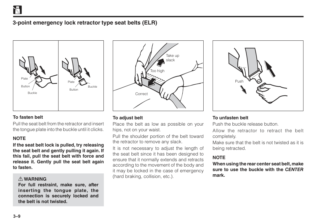
3–9 3-point emergency lock retractor type seat belts (ELR) To fasten belt Pull the seat belt from the retractor and insert the tongue plate into the buckle until it clicks.
Note
If the seat belt lock is pulled, try releasing the seat belt and gently pulling it again. If this fail, pull the seat belt with force and release it. Gently pull the seat belt again to fasten. w WARNING For full restraint, make sure, after inserting the tongue plate, the connection is securely locked and the belt is not twisted. Plate Plate Button Button Buckle Buckle To adjust belt Place the belt as low as possible on your hips, not on your waist. Pull the shoulder portion of the belt toward the retractor to remove any slack. It is not necessary to adjust the length of the seat belt since it has been designed to ensure that it normally extends and retracts according to the movement of the body and it may be locked in the case of emergency (hard braking, collision, etc.). Take up slack Correct Too high To unfasten belt Push the buckle release button. Allow the retractor to retract the belt completely. Make sure that the belt is not twisted as it is being retracted.Note
When using the rear center seat belt, make sure to use the buckle with the CENTER mark. Push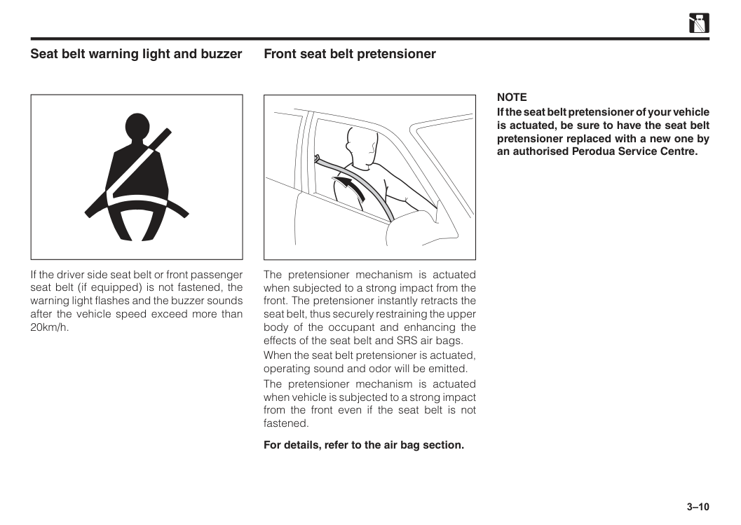
3–10 Seat belt warning light and buzzer If the driver side seat belt or front passenger seat belt (if equipped) is not fastened, the warning light flashes and the buzzer sounds after the vehicle speed exceed more than 20km/h. Front seat belt pretensioner The pretensioner mechanism is actuated when subjected to a strong impact from the front. The pretensioner instantly retracts the seat belt, thus securely restraining the upper body of the occupant and enhancing the effects of the seat belt and SRS air bags. When the seat belt pretensioner is actuated, operating sound and odor will be emitted. The pretensioner mechanism is actuated when vehicle is subjected to a strong impact from the front even if the seat belt is not fastened. For details, refer to the air bag section.
Note
If the seat belt pretensioner of your vehicle is actuated, be sure to have the seat belt pretensioner replaced with a new one by an authorised Perodua Service Centre.
3–11
Note
There are cases where the force limiter mechanism will not operate even when the pretensioner mechanism has operated. Force limiter mechanism w WARNING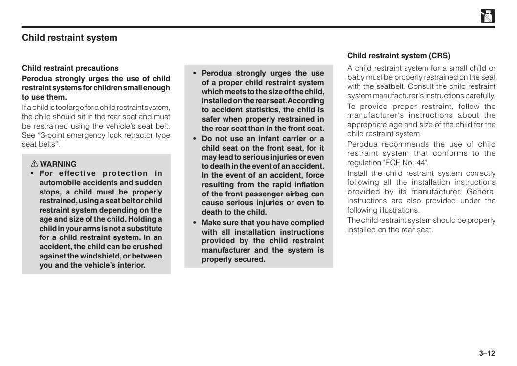
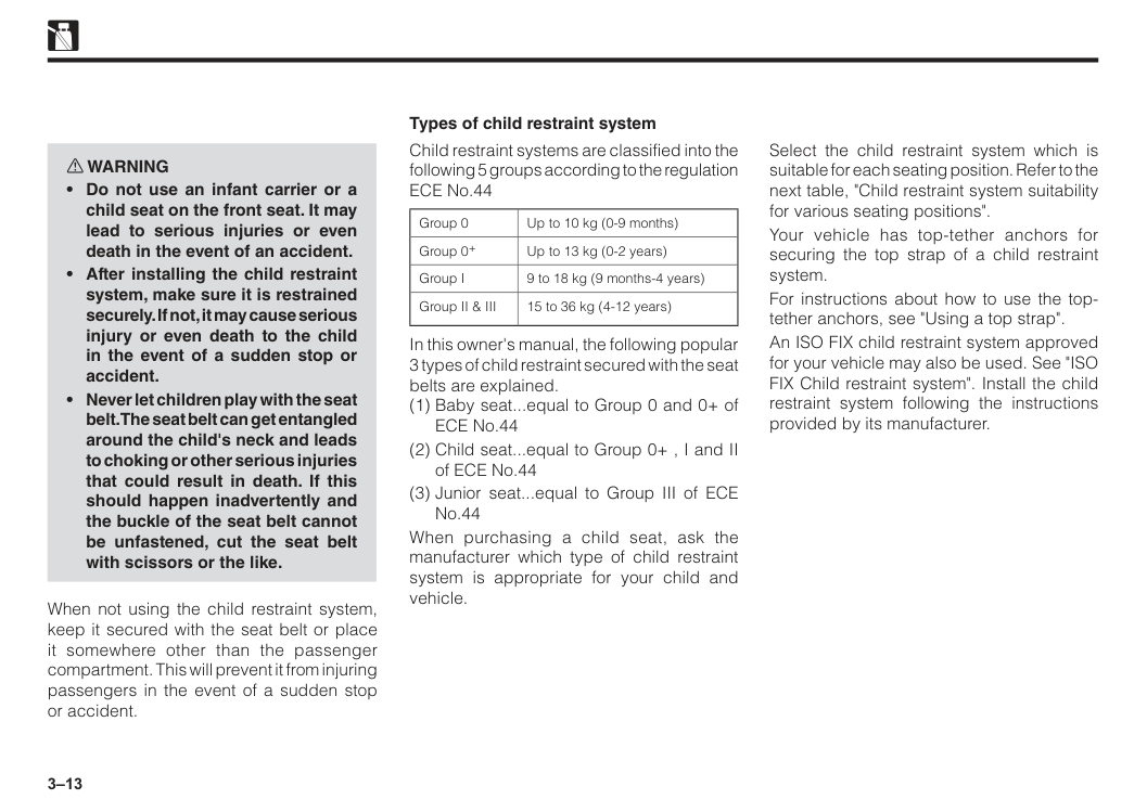
3–12 Child restraint system Child restraint precautions Perodua strongly urges the use of child restraint systems for children small enough to use them. If a child is too large for a child restraint system, the child should sit in the rear seat and must be restrained using the vehicle’s seat belt. See “3-point emergency lock retractor type seat belts”. w WARNING
3–13 w WARNING
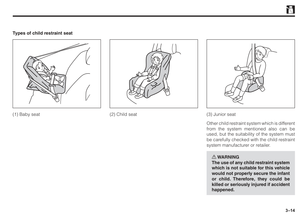
3–14 Types of child restraint seat (1) Baby seat (2) Child seat (3) Junior seat Other child restraint system which is different from the system mentioned also can be used, but the suitability of the system must be carefully checked with the child restraint system manufacturer or retailer. w WARNING The use of any child restraint system which is not suitable for this vehicle would not properly secure the infant or child. Therefore, they could be killed or seriously injured if accident happened.
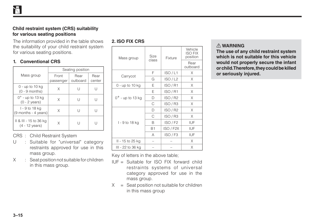
3–15 The information provided in the table shows the suitability of your child restraint system for various seating positions.
X
U
U
0+ - up to 13 kg (0 - 2 years)X
U
U
I - 9 to 18 kg (9 months - 4 years)X
U
U
II & III - 15 to 36 kg (4 - 12 years)X
U
U
CRS : Child Restraint SystemU
: Suitable for "universal" category restraints approved for use in this mass group.X
: Seat position not suitable for children in this mass group. Child restraint system (CRS) suitability for various seating positions2. Iso Fix Crs
Mass group Size class Fixture VehicleIso Fix
position Rear outboard CarrycotF
Iso / L1
X
G
Iso / L2
X
0 - up to 10 kgE
Iso / R1
X
0+ - up to 13 kgE
Iso / R1
X
D
Iso / R2
X
C
Iso / R3
X
I - 9 to 18 kgD
Iso / R2
X
C
Iso / R3
X
B
Iso / F2
Iuf
B1
Iso / F2X
Iuf
A
Iso / F3
Iuf
II - 15 to 25 kg – –X
III - 22 to 36 kg – –X
Key of letters in the above table; IUF = Suitable for ISO FIX forward child restraints systems of universal category approved for use in the mass group.X
= Seat position not suitable for children in this mass group w WARNING The use of any child restraint system which is not suitable for this vehicle would not properly secure the infant or child. Therefore, they could be killed or seriously injured.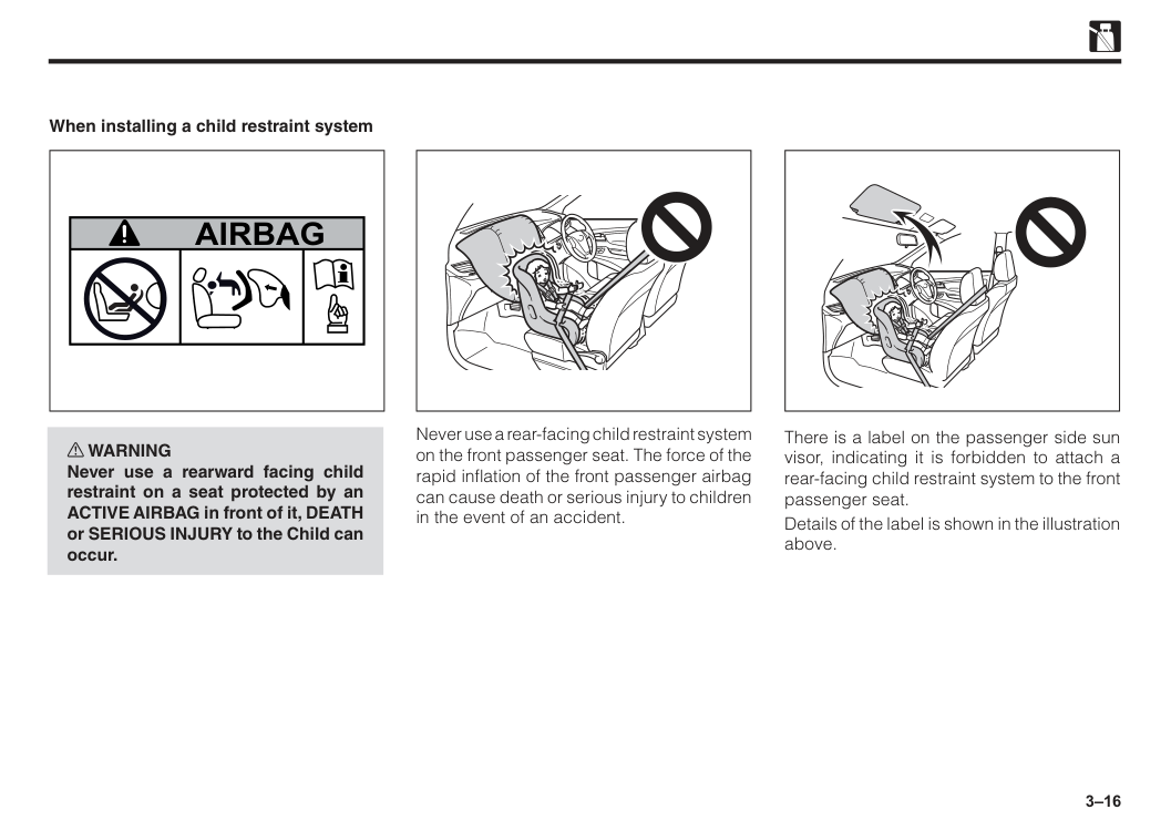
3–16 When installing a child restraint system w WARNING Never use a rearward facing child restraint on a seat protected by an ACTIVE AIRBAG in front of it, DEATH or SERIOUS INJURY to the Child can occur.
Airbag
Never use a rear-facing child restraint system on the front passenger seat. The force of the rapid inflation of the front passenger airbag can cause death or serious injury to children in the event of an accident. There is a label on the passenger side sun visor, indicating it is forbidden to attach a rear-facing child restraint system to the front passenger seat. Details of the label is shown in the illustration above.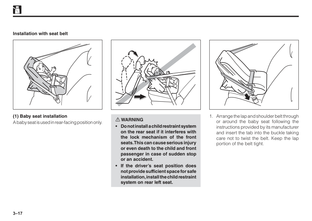
3–17 Installation with seat belt (1) Baby seat installation A baby seat is used in rear-facing position only. w WARNING
3–18 w WARNING
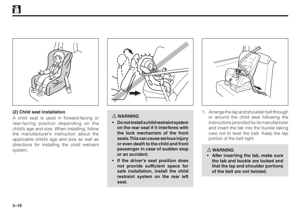
3–19 (2) Child seat installation A child seat is used in forward-facing or rear-facing position depending on the child’s age and size. When installing, follow the manufacturer’s instruction about the applicable child’s age and size as well as directions for installing the child restraint system. w WARNING
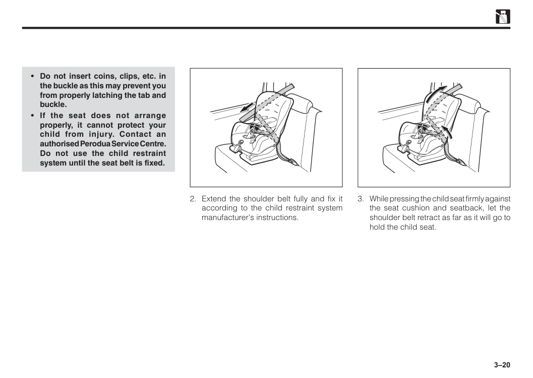
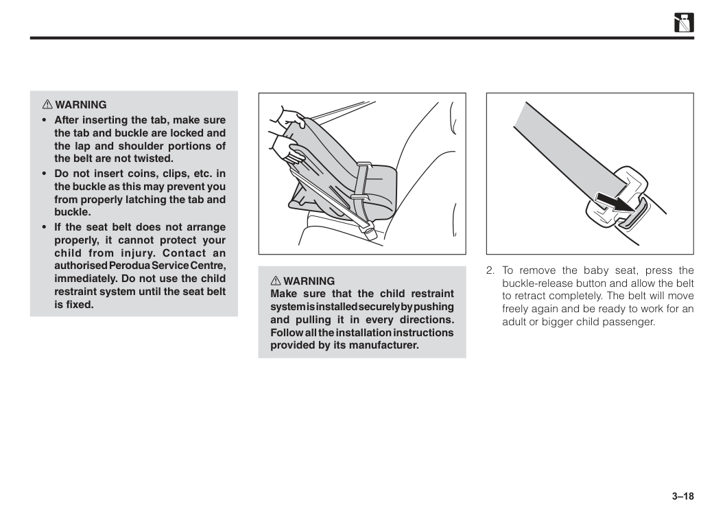
3–20
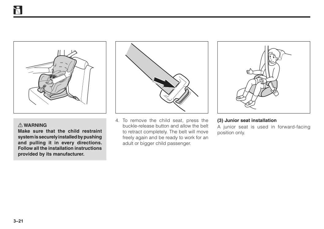
3–21 w WARNING Make sure that the child restraint system is securely installed by pushing and pulling it in every directions. Follow all the installation instructions provided by its manufacturer.
3–22

3–23 Top strap If your child restraint system has a top strap, it should be anchored. Follow the procedure below for a child restraint system that requires the use of a top strap. Using a top strap Using top-tether anchors Top-tether anchors location Use the top-tether anchors as shown in the figure to attach the top strap. Top-tether anchors are installed for each rear seating position. The symbol indicates the locations of user ready top-tether anchors.
Make sure the top strap is securely latched.
3–24 w WARNING
Note
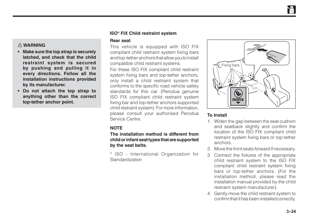
The installation method is different from child or infant seat types that are supported by the seat belts.Isofix
To Install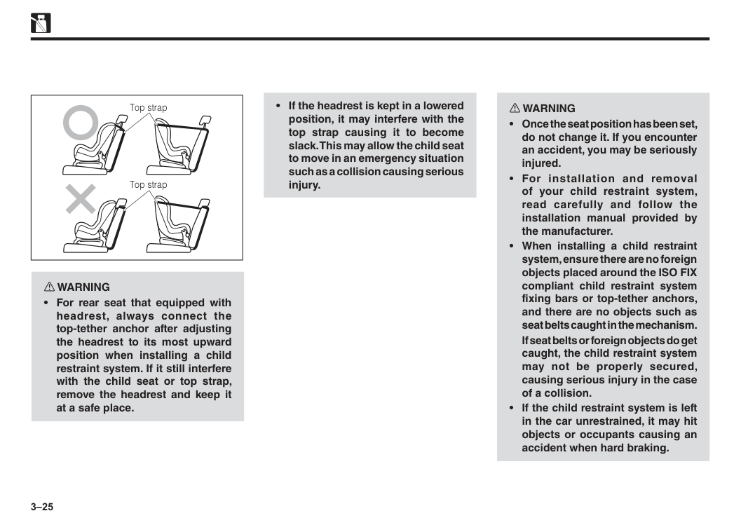
3–25 w WARNING
If seat belts or foreign objects do get caught, the child restraint system may not be properly secured, causing serious injury in the case of a collision.
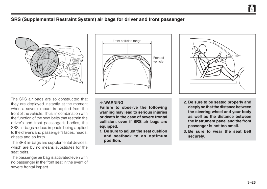
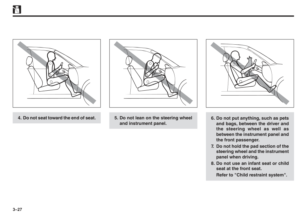
3–26 SRS (Supplemental Restraint System) air bags for driver and front passenger The SRS air bags are so constructed that they are deployed instantly at the moment when a severe impact is applied from the front of the vehicle. Thus, in combination with the function of the seat belts that restrain the driver’s and front passenger’s bodies, the SRS air bags reduce impacts being applied to the driver’s and passenger’s faces, heads, chests and so forth. The SRS air bags are supplemental devices, which are by no means substitutes for the seat belts. The passenger air bag is activated even with no passenger in the front seat in the event of severe frontal impact. w WARNING Failure to observe the following warning may lead to serious injuries or death in the case of severe frontal collision, even if SRS air bags are equipped.
3–27
Refer to "Child restraint system".
3–28
Refer to "Instructions on seat belts ".
For more details of the warning, see the following NOTE.
Note
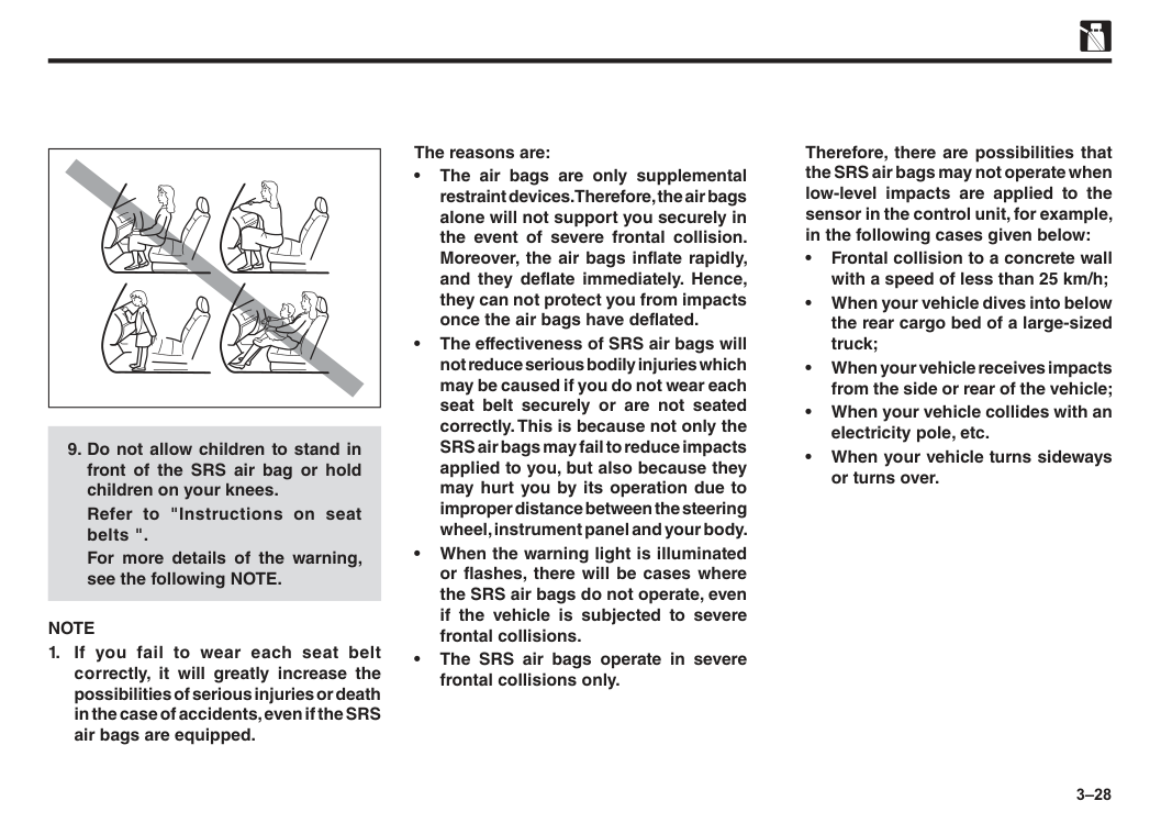
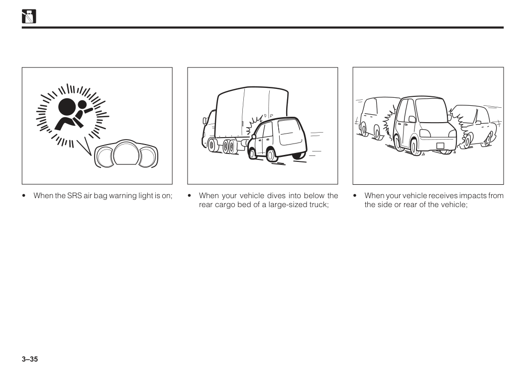
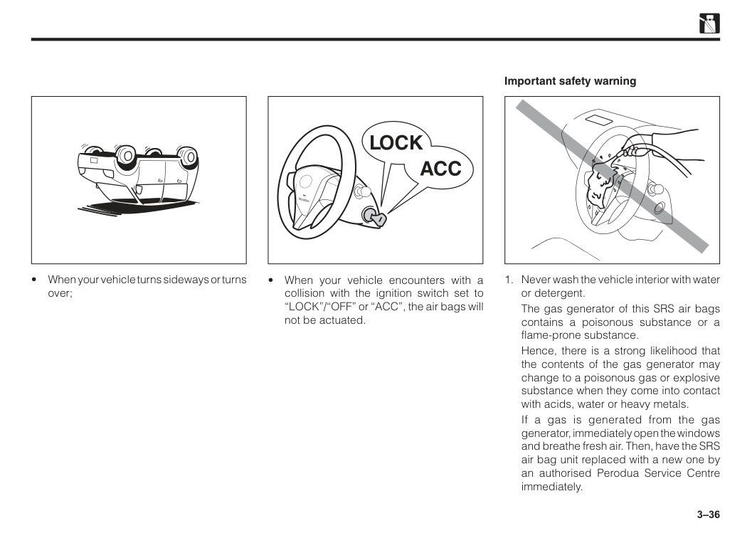
Therefore, there are possibilities that the SRS air bags may not operate when low-level impacts are applied to the sensor in the control unit, for example, in the following cases given below: • Frontal collision to a concrete wall with a speed of less than 25 km/h; • When your vehicle dives into below the rear cargo bed of a large-sized truck; • When your vehicle receives impacts from the side or rear of the vehicle; • When your vehicle collides with an electricity pole, etc. • When your vehicle turns sideways or turns over.
3–29
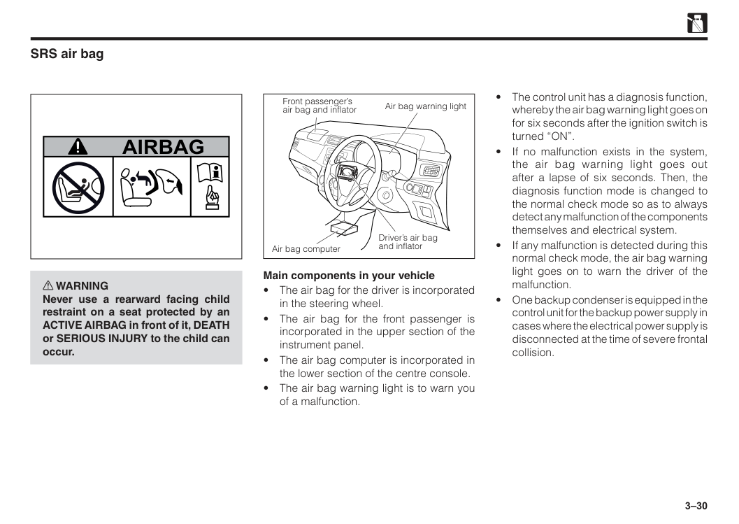
3–30 w WARNING Never use a rearward facing child restraint on a seat protected by an ACTIVE AIRBAG in front of it, DEATH or SERIOUS INJURY to the child can occur.
Airbag
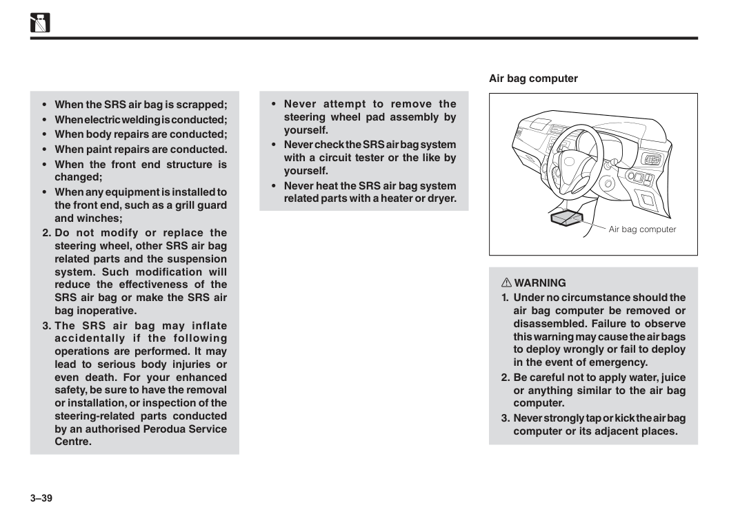
SRS air bag Main components in your vehicle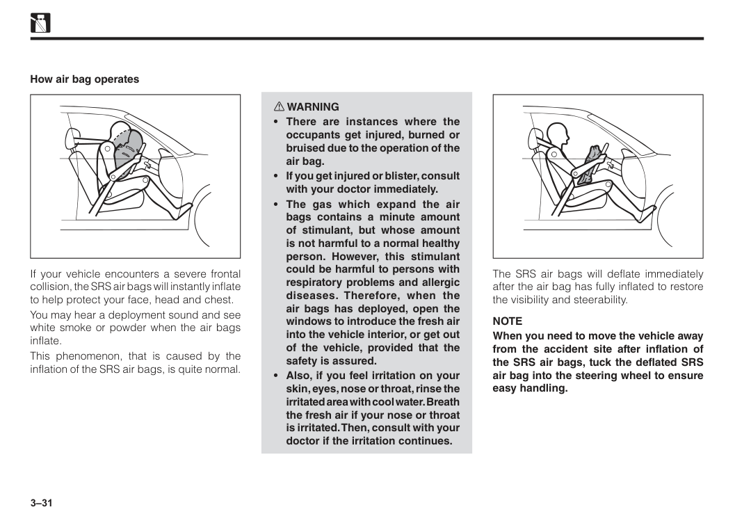
3–31 If your vehicle encounters a severe frontal collision, the SRS air bags will instantly inflate to help protect your face, head and chest. You may hear a deployment sound and see white smoke or powder when the air bags inflate. This phenomenon, that is caused by the inflation of the SRS air bags, is quite normal. How air bag operates w WARNING
Note
When you need to move the vehicle away from the accident site after inflation of the SRS air bags, tuck the deflated SRS air bag into the steering wheel to ensure easy handling.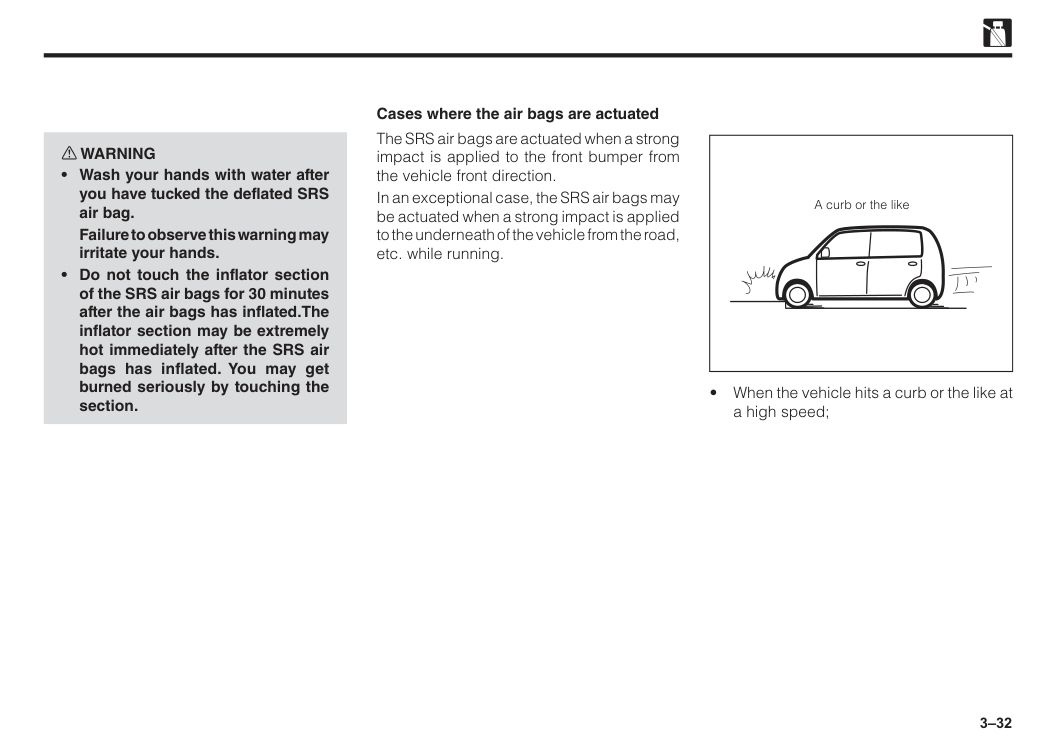
3–32 w WARNING
Failure to observe this warning may irritate your hands.
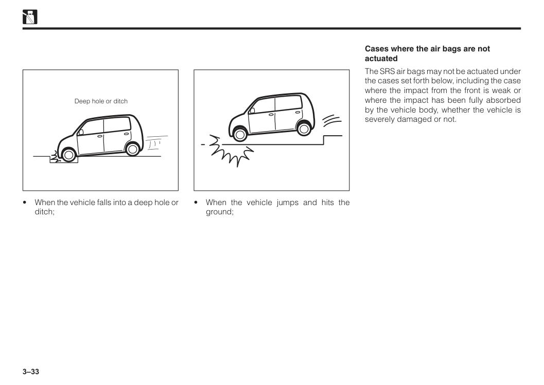
3–33 Deep hole or ditch
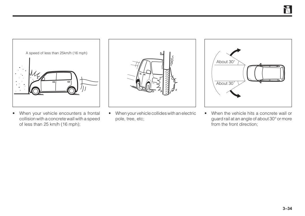
3–34 A speed of less than 25km/h (16 mph)
3–35
3–36
Srs Airbag
The gas generator of this SRS air bags contains a poisonous substance or a flame-prone substance.
Hence, there is a strong likelihood that the contents of the gas generator may change to a poisonous gas or explosive substance when they come into contact with acids, water or heavy metals.
If a gas is generated from the gas generator, immediately open the windows and breathe fresh air. Then, have the SRS air bag unit replaced with a new one by an authorised Perodua Service Centre immediately. Important safety warning
Ag
3–37
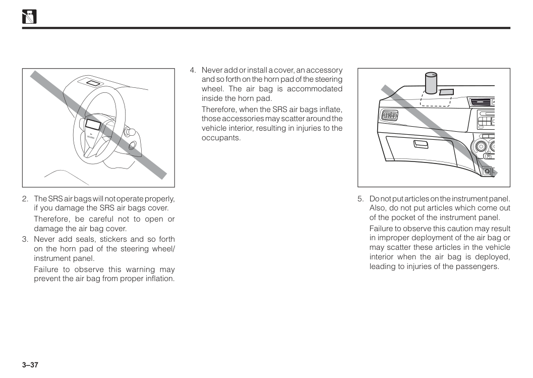
Therefore, be careful not to open or damage the air bag cover.
Failure to observe this warning may prevent the air bag from proper inflation.
Srs Airbag
Therefore, when the SRS air bags inflate, those accessories may scatter around the vehicle interior, resulting in injuries to the occupants.
Failure to observe this caution may result in improper deployment of the air bag or may scatter these articles in the vehicle interior when the air bag is deployed, leading to injuries of the passengers.
3–38
When the air bag is deployed, accessories may scatter in the vehicle interior, leading to injuries of the passengers.
It may lead to injuries of the passengers when the air bag is deployed.
Failure to observe the instruction, caution and warning described in the relevant service manuals prepared by Perodua may result in serious personal injuries, death or damage to the system.
When you sell your vehicle, be sure to inform the buyers about the equipment of the air bags.
Do not remove or destroy the inflated air bags by yourself.
3–39
3–40
3–41
Note
EDR data are recorded by your vehicle only if a non-trivial crash situation occurs; no data are recorded by the EDR under normal driving conditions and no personal data (e.g., name, gender, age, and crash location) are recorded. However, other parties, such as law enforcement, could combine the EDR data with the type of personally identifying data routinely acquired during a crash investigation. To read data recorded by an EDR, special equipment is required, and access to the vehicle or the EDR is needed. In addition to the vehicle manufacturer, other parties, such as law enforcement, that have the special equipment, can read the information if they have access to the vehicle or the EDR. Disclosure of the EDR data Perodua will not disclose the data recorded in an EDR to a third party except when:
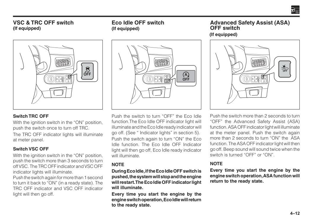
4 Ignition switch..................................................................................4–1 Push start system.............................................................................4–2 Key reminder buzzer........................................................................4–6 Multi-control switch..........................................................................4–7 Auto light off function......................................................................4–9 Wiper and washer control lever......................................................4–9 Hazard warning signal switch.........................................................4–10 Rear window defogger switch.........................................................4–10 Central doors lock switch................................................................4–11 Front corner sensor switch..............................................................4–11 Front passenger seat belt indicator................................................4–11 VSC & TRC OFF switch....................................................................4–12 Eco Idle OFF switch.........................................................................4–12 Advanced Safety Assist (ASA) OFF switch....................................4–12 Power socket.....................................................................................4–13 Rear USB phone charging...............................................................4–13 Stereo camera...................................................................................4–14 Section 4 Instruments and controls
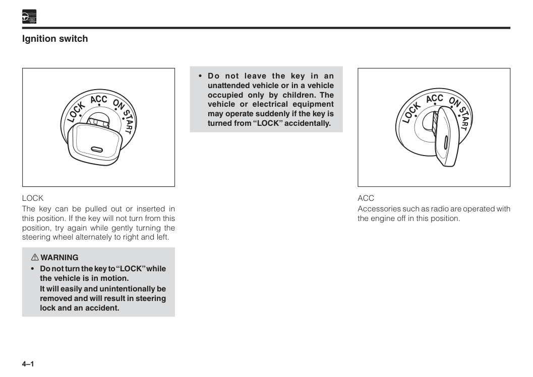
4–1 Ignition switch
Acc
Accessories such as radio are operated with the engine off in this position.Lock
The key can be pulled out or inserted in this position. If the key will not turn from this position, try again while gently turning the steering wheel alternately to right and left. w WARNINGIt will easily and unintentionally be removed and will result in steering lock and an accident.
4–2
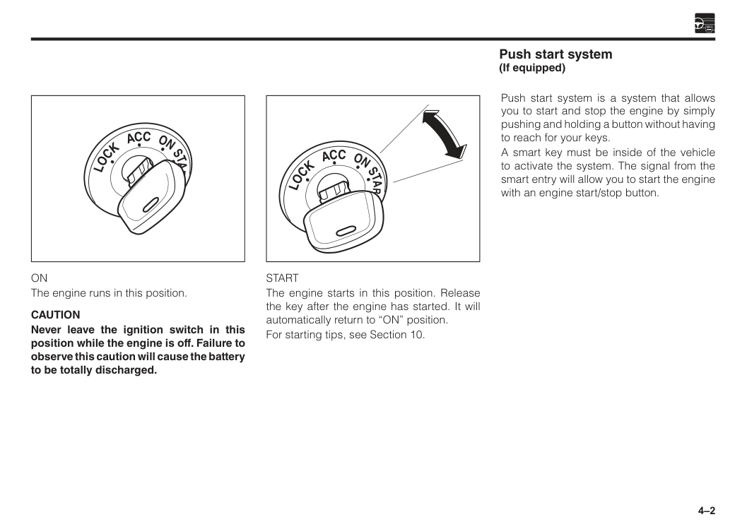
Start
The engine starts in this position. Release the key after the engine has started. It will automatically return to “ON” position. For starting tips, see Section 10.On
The engine runs in this position.Caution
Never leave the ignition switch in this position while the engine is off. Failure to observe this caution will cause the battery to be totally discharged. Push start system is a system that allows you to start and stop the engine by simply pushing and holding a button without having to reach for your keys. A smart key must be inside of the vehicle to activate the system. The signal from the smart entry will allow you to start the engine with an engine start/stop button. Push start system (If equipped)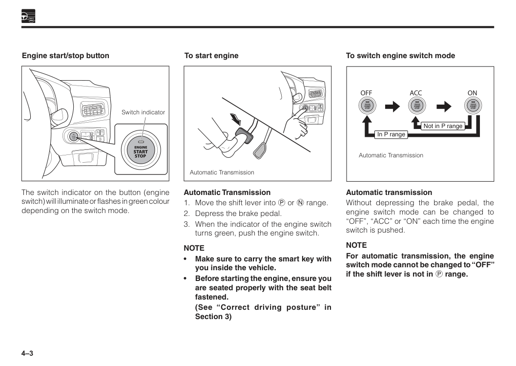
4–3 The switch indicator on the button (engine switch) will illuminate or flashes in green colour depending on the switch mode. Automatic Transmission
Note
• Make sure to carry the smart key with you inside the vehicle. • Before starting the engine, ensure you are seated properly with the seat belt fastened.(See “Correct driving posture” in Section 3) Engine start/stop button To start engine
R
L
Mirror
Engine
Start
Stop
Off
Off
Off
A
Switch indicator Automatic TransmissionR
L
Mirror
Engine
Start
Stop
Off
Off
Off
A
Automatic transmission Without depressing the brake pedal, the engine switch mode can be changed to “OFF”, “ACC” or “ON” each time the engine switch is pushed.Note
For automatic transmission, the engine switch mode cannot be changed to “OFF” if the shift lever is not in P range. To switch engine switch modeOff
Acc
On
Not in P range In P range Automatic Transmission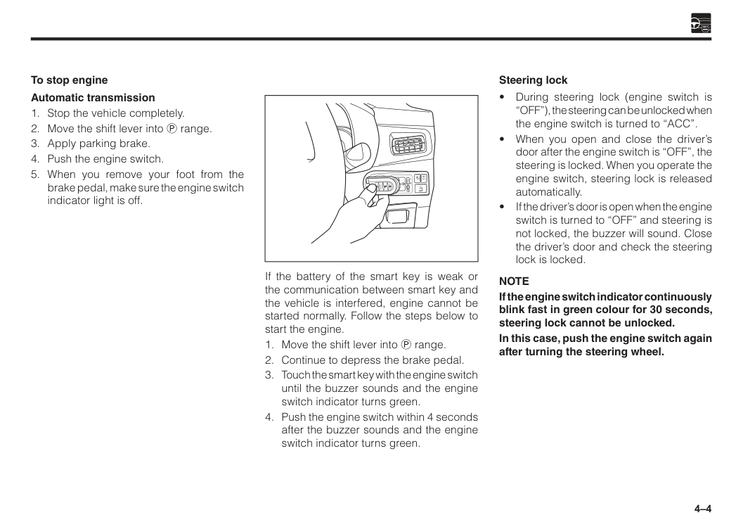
4–4 If the battery of the smart key is weak or the communication between smart key and the vehicle is interfered, engine cannot be started normally. Follow the steps below to start the engine.
R
L
Mirror
Engine
Start
Stop
Off
Off
Off
A
Note
If the engine switch indicator continuously blink fast in green colour for 30 seconds, steering lock cannot be unlocked. In this case, push the engine switch again after turning the steering wheel. Steering lock
4–5
Caution
• If the engine switch indicator light changes to orange colour, the system may be malfunctioning. Without switching “OFF” the engine, contact an authorised Perodua Service Centre. (If you switched “OFF” the engine, the engine may have a problem to restart again) • If you notice the engine switch is different from its normal condition such as the following, do not operate the switch. • The engine switch stuck or get caught • Drinks or liquid spilled on the switch. • The engine switch indicator light is not turned “ON” even after you have turned on the clearance lights.Please contact an authorised Perodua Service Centre immediately. Precaution for engine switch w WARNING Emergency engine stop method When you do the following operations, engine will stop even while running. However, do not operate the engine switch except in an emergency while running. It may lead to an unexpected accident.
Note
• If stopping and starting of the engine repeatedly at short intervals, there are cases where the engine cannot be started.Wait for more than about 10 seconds and perform the start-up operation of the engine again. • If you push the engine switch too fast, you may not be able to switch modes (engine start/stop). Make sure to push the switch one by one. • To prevent battery from running out, during engine switched off, do not let the engine switch turned to “ON” in a long time. • For automatic transmission vehicle, if the shift lever is other than P range, do not stop the engine.
If you stop the engine when the shift lever is other than P range, engine switch will change to “ACC” mode. This could cause the battery flat. • There are cases where the engine switch is not working correctly even the smart key is within the operating range. It may depend on the location of the smart key and surrounding conditions.
4–6 • Warning buzzer of the key free system will sound if operation error is detected such as taking out smart key from vehicle, or forget to turn “OFF” engine switch without closing the door. • Do not take the smart key out from vehicle once the engine is started. If the smart key is not in the vehicle and you turn the engine “OFF”, the engine cannot be restarted again.
Please note that the buzzer will not sound if you take out the smart key through the window even though the door is closed. • After disconnecting the battery terminal, the engine may not be started immediately. In this case, after the battery terminal is connected, wait for more than 10 seconds and restart the engine again. • The vehicle always remembers the engine switch mode (“ACC” or “ON”). When you reconnect the battery of the vehicle, it can return to the state it was in before the engine switch was cut off. • When you remove the battery of the vehicle for repair, maintenance etc., always perform after the engine switch is turned “OFF”. • If the battery is weak and you are not sure the previous engine switch mode, turn “OFF” the engine switch once. Engine switch automatic “OFF” • Automatic transmission:
When the shift lever is in P range, and you leave the engine switch in “ACC” mode for about 1 hour, the engine switch will be turned “OFF” automatically to prevent the battery from running out. Key reminder buzzer This buzzer is set off when the driver’s door is opened with the ignition is set to “ACC” or “LOCK”, warning you to remove the ignition key.
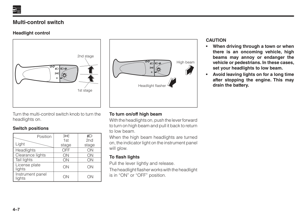
4–7 Multi-control switch Headlight control To turn on/off high beam With the headlights on, push the lever forward to turn on high beam and pull it back to return to low beam. When the high beam headlights are turned on, the indicator light on the instrument panel will glow. To flash lights Pull the lever lightly and release. The headlight flasher works with the headlight is in “ON” or “OFF” position. Turn the multi-control switch knob to turn the headlights on. Switch positions Position Light Headlights Clearance lights Tail lights License plate lights Instrument panel lights
On
On
On
On
On
Off
On
On
On
On
2nd stage 1st stage 2nd stage 1st stage High beam Headlight flasherCaution
• When driving through a town or when there is an oncoming vehicle, high beams may annoy or endanger the vehicle or pedestrians. In these cases, set your headlights to low beam. • Avoid leaving lights on for a long time after stopping the engine. This may drain the battery.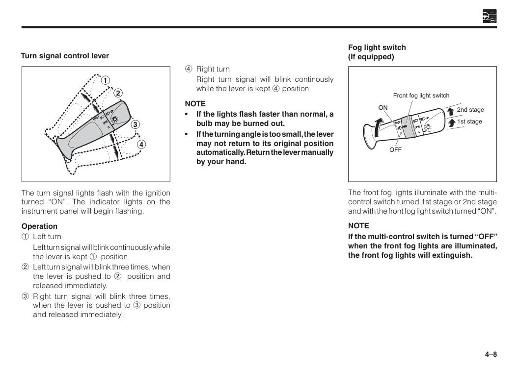
4–8 Turn signal control lever The turn signal lights flash with the ignition turned “ON”. The indicator lights on the instrument panel will begin flashing. Operation 1 Left turn
Left turn signal will blink continuously while the lever is kept 1 position. 2 Left turn signal will blink three times, when the lever is pushed to 2 position and released immediately. 3 Right turn signal will blink three times, when the lever is pushed to 3 position and released immediately. 4 Right turn
Right turn signal will blink continously while the lever is kept 4 position.
Note
• If the lights flash faster than normal, a bulb may be burned out. • If the turning angle is too small, the lever may not return to its original position automatically. Return the lever manually by your hand. 1 3 4 2 Fog light switch (If equipped) The front fog lights illuminate with the multi- control switch turned 1st stage or 2nd stage and with the front fog light switch turned “ON”.Note
If the multi-control switch is turned “OFF” when the front fog lights are illuminated, the front fog lights will extinguish. Front fog light switchOn
Off
1st stage 2nd stage
4–9 Auto light off function For the purpose of preventing flat battery on the vehicle, the lights are automatically turned off if the driver’s door is opened when the engine switch is turned to “OFF” or “ACC” while the lights are on. Wiper and washer control lever w WARNING
Caution
• Washer tank shall be filled with washer fluid only. • Do not operate the washer if the washer tank is empty. This may damage the motor. • Do not operate the wiper when the window is dry. This may damage the wiper blades. • After long periods of non-use, check that the wiper blade is not stuck to the window glass. Operating the wipers while stuck to the window glass may damage the wiper motor or cause a malfunction. • Avoid spraying the washer fluid continuously for more than 20 seconds. Also, avoid operating the washer switch if there is something preventing the washer fluid from spraying out. This may overload the motor, leading to damage. • When raising the wiper arms, be sure to raise the wiper arm on the right side of the vehicle first. When returning the wiper arms to their original positions, be sure to return the wiper arm on the left side of the vehicle first.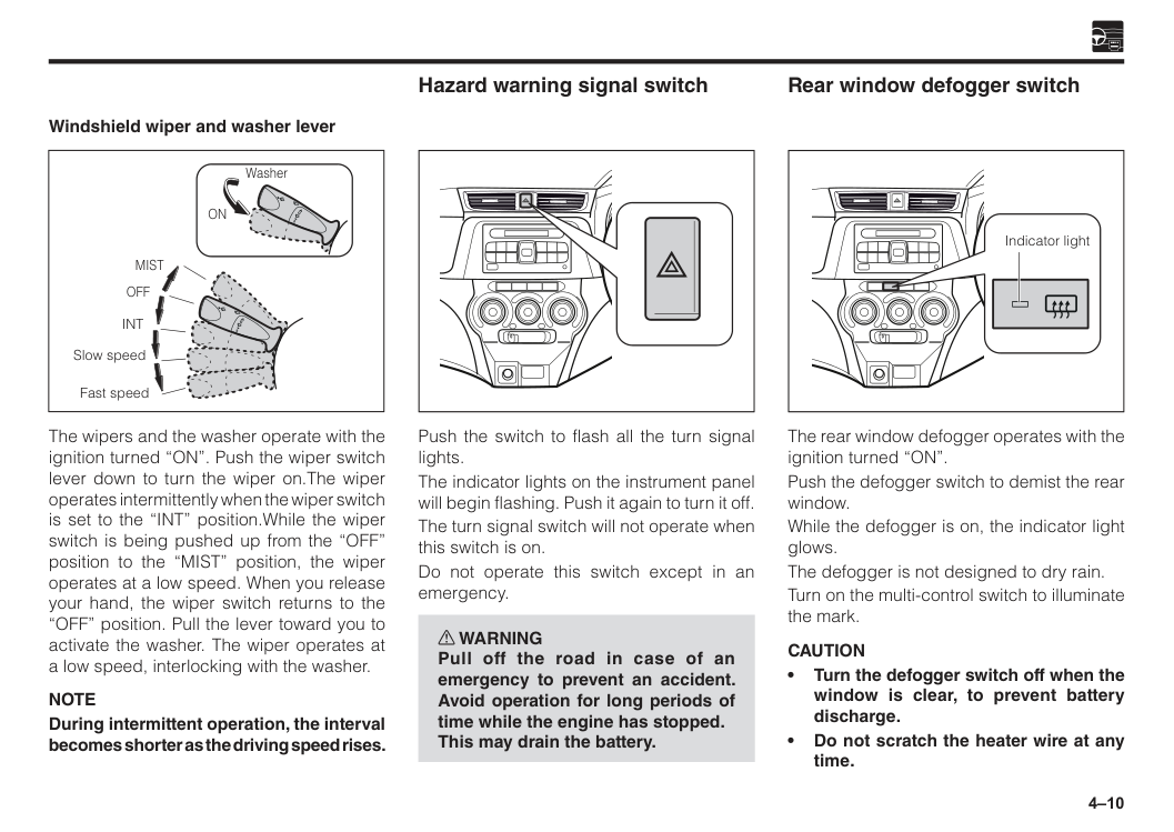
4–10 Rear window defogger switch The rear window defogger operates with the ignition turned “ON”. Push the defogger switch to demist the rear window. While the defogger is on, the indicator light glows. The defogger is not designed to dry rain. Turn on the multi-control switch to illuminate the mark.
Caution
• Turn the defogger switch off when the window is clear, to prevent battery discharge. • Do not scratch the heater wire at any time. Indicator light Windshield wiper and washer lever The wipers and the washer operate with the ignition turned “ON”. Push the wiper switch lever down to turn the wiper on.The wiper operates intermittently when the wiper switch is set to the “INT” position.While the wiper switch is being pushed up from the “OFF” position to the “MIST” position, the wiper operates at a low speed. When you release your hand, the wiper switch returns to the “OFF” position. Pull the lever toward you to activate the washer. The wiper operates at a low speed, interlocking with the washer.Note
During intermittent operation, the interval becomes shorter as the driving speed rises.Off
Mist
Int
Slow speed Fast speed WasherOn
Push the switch to flash all the turn signal lights. The indicator lights on the instrument panel will begin flashing. Push it again to turn it off. The turn signal switch will not operate when this switch is on. Do not operate this switch except in an emergency. w WARNING Pull off the road in case of an emergency to prevent an accident. Avoid operation for long periods of time while the engine has stopped. This may drain the battery. Hazard warning signal switch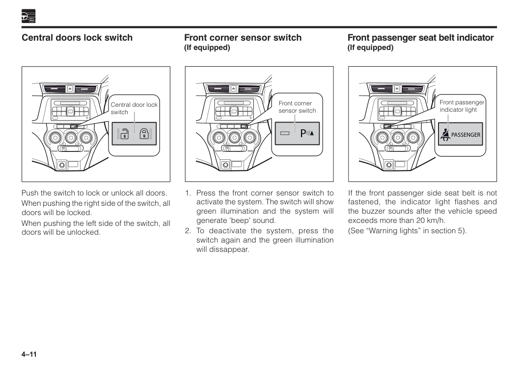
4–11 Central door lock switch Central doors lock switch Push the switch to lock or unlock all doors. When pushing the right side of the switch, all doors will be locked. When pushing the left side of the switch, all doors will be unlocked. If the front passenger side seat belt is not fastened, the indicator light flashes and the buzzer sounds after the vehicle speed exceeds more than 20 km/h. (See “Warning lights” in section 5). Front passenger seat belt indicator (If equipped) Front passenger indicator light
Passenger
P
4–12
R
L
Mirror
Engine
Start
Stop
Off
Off
Off
A
Off
Switch TRC OFF With the ignition switch in the “ON” position, push the switch once to turn off TRC. The TRC OFF indicator lights will illuminate at meter panel. Switch VSC OFF With the ignition switch in the “ON” position, push the switch more than 3 seconds to turn off VSC. The TRC OFF indicator and VSC OFF indicator lights will illuminate. Push the switch again for more than 1 second to turn it back to “ON” (in a ready state). The TRC OFF indicator and VSC OFF indicator light will then go off. VSC & TRC OFF switch (If equipped) Push the switch to turn “OFF” the Eco Idle function.The Eco Idle OFF indicator light will illuminate and the Eco Idle ready indicator will go off. (See “ Indicator lights” in section 5). Push the switch again to turn “ON” the Eco Idle function. The Eco Idle OFF Indicator light will then go off, Eco Idle ready indicator will illuminate.Note
During Eco Idle, if the Eco Idle OFF switch is pushed, the system will stop and the engine will restart. The Eco Idle OFF indicator light will illuminate. Every time you start the engine by the engine switch operation, Eco Idle will return to the ready state. Eco Idle OFF switch (If equipped)R
L
Mirror
Engine
Start
Stop
Off
Off
Off
A
Off
A
Advanced Safety Assist (ASA) OFF switch Push the switch more than 2 seconds to turn “OFF” the Advanced Safety Assist (ASA) function. ASA OFF indicator light will illuminate at the meter panel. Push the switch again more than 2 seconds to turn “ON” the ASA function. The ASA OFF indicator light will then go off. Beep sound will sound twice when the switch is turned “OFF” or “ON”.Note
Every time you start the engine by the engine switch operation, ASA function will return to the ready state.R
L
Mirror
Engine
Start
Stop
Off
Off
Off
A
Off
(If equipped)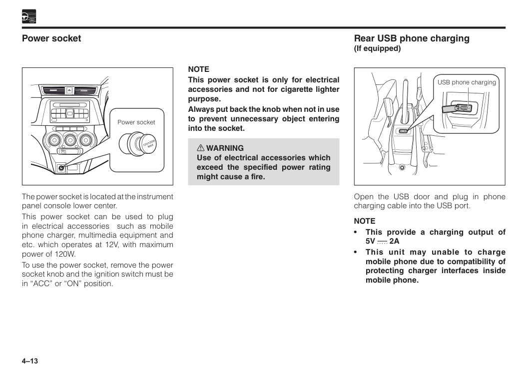
4–13 The power socket is located at the instrument panel console lower center. This power socket can be used to plug in electrical accessories such as mobile phone charger, multimedia equipment and etc. which operates at 12V, with maximum power of 120W. To use the power socket, remove the power socket knob and the ignition switch must be in “ACC” or “ON” position. Power socket Power socket
12V/120W
Max
Rear USB phone charging (If equipped) USB phone charging Open the USB door and plug in phone charging cable into the USB port.Note
• This provide a charging output of5V
2A
• This unit may unable to charge mobile phone due to compatibility of protecting charger interfaces inside mobile phone.Note
This power socket is only for electrical accessories and not for cigarette lighter purpose. Always put back the knob when not in use to prevent unnecessary object entering into the socket. w WARNING Use of electrical accessories which exceed the specified power rating might cause a fire.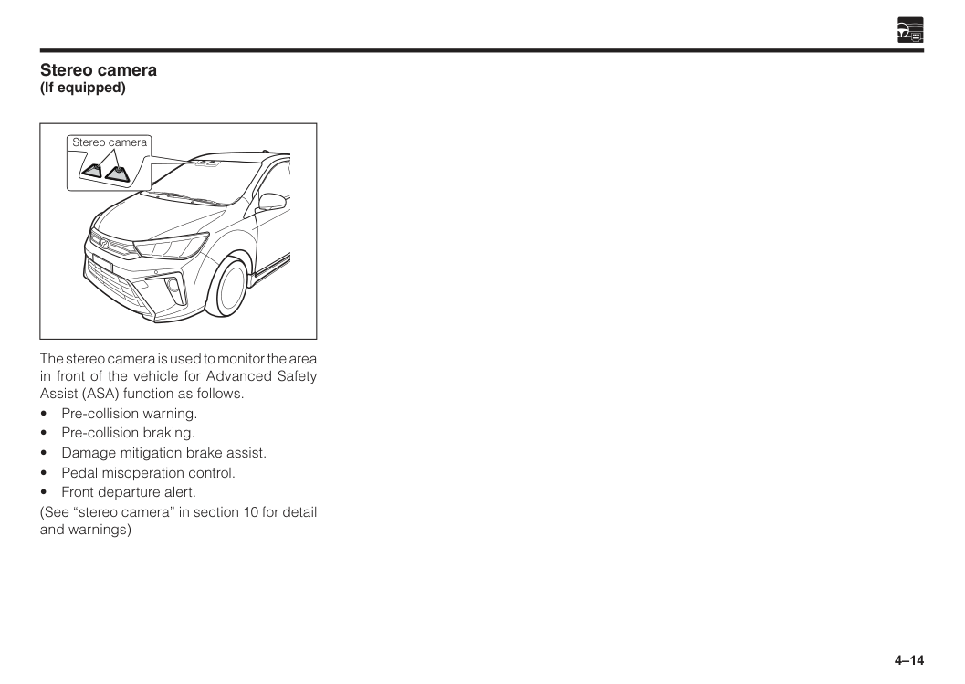
4–14 Stereo camera (If equipped) The stereo camera is used to monitor the area in front of the vehicle for Advanced Safety Assist (ASA) function as follows.
5 Combination meter panel overview................................................5–1 Warning lights...................................................................................5–2 Indicator lights..................................................................................5–10 Fuel gauge.........................................................................................5–15 Odometer and trip meter..................................................................5–16 Multi information display.................................................................5–16 Speedometer.....................................................................................5–21 Tachometer.......................................................................................5–21 During meter usage..........................................................................5–21 Section 5 Meters and gauges
5–1 Combination meter panel overview Type 2 Type 1 eco
At
Off
Trc
Off
Off
P
Off
A
A
A
4F
E
! 2 1 0 0 20 40 60 80 100 120 140 160 180 200 3 x1000r/min km/hOdo/Trip Disp
A S A Off
Error
Odo
Range
6 7 8 5 4 km/LTripavgcfc
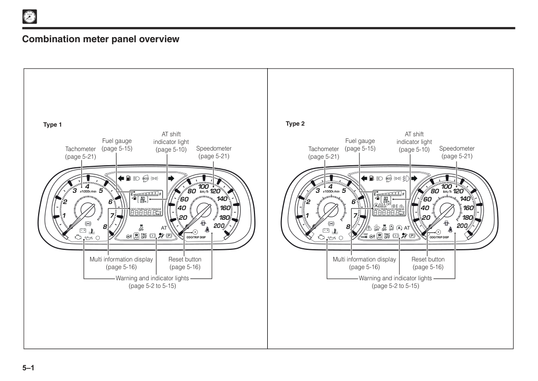
Speedometer (page 5-21) AT shift indicator light (page 5-10) Fuel gauge (page 5-15) Tachometer (page 5-21) Reset button (page 5-16) Multi information display (page 5-16) Warning and indicator lights (page 5-2 to 5-15) ecoAt
Trc
Off
Off
P
4F
E
! 2 1 0 0 20 40 60 80 100 120 140 160 180 200 3 x1000r/min km/hOdo/Trip Disp
Odo
Range
6 7 8 5 4 km/LTripavgcfc
Speedometer (page 5-21) AT shift indicator light (page 5-10) Fuel gauge (page 5-15) Tachometer (page 5-21) Reset button (page 5-16) Multi information display (page 5-16) Warning and indicator lights (page 5-2 to 5-15)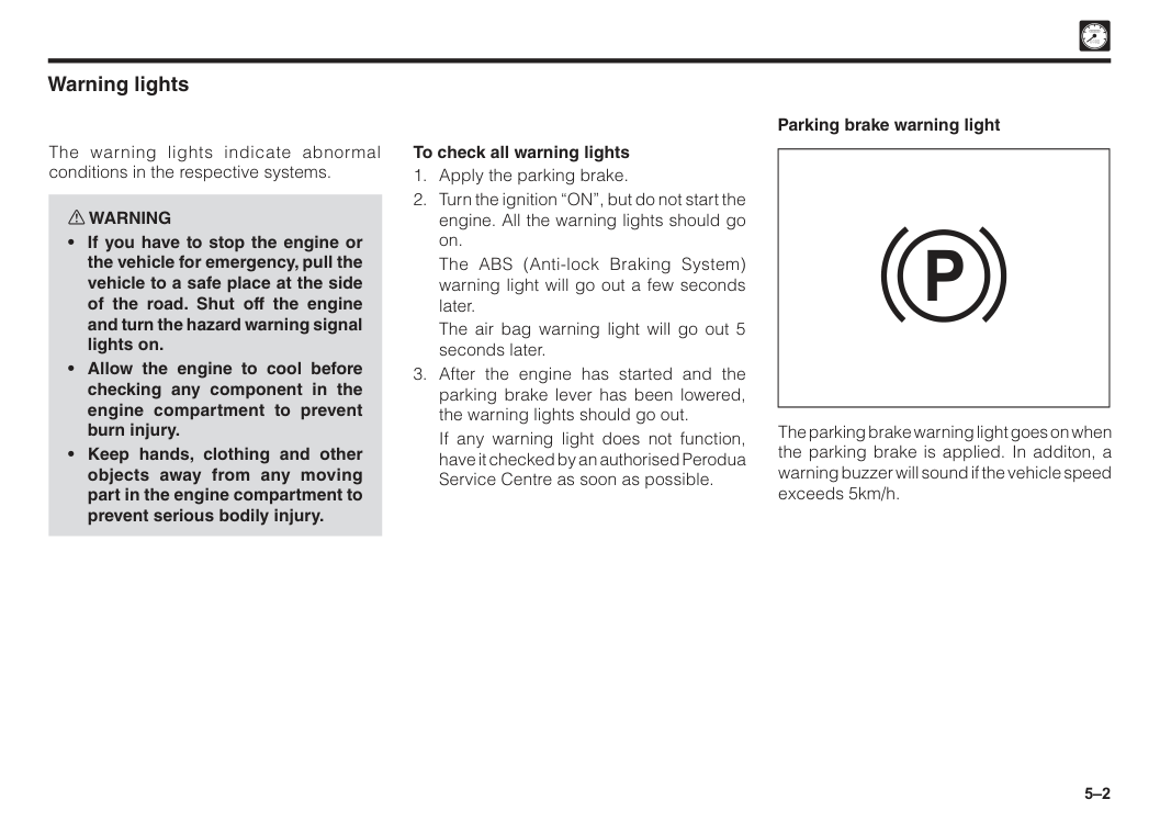
5–2 Warning lights The warning lights indicate abnormal conditions in the respective systems. w WARNING
The ABS (Anti-lock Braking System) warning light will go out a few seconds later.
The air bag warning light will go out 5 seconds later.
If any warning light does not function, have it checked by an authorised Perodua Service Centre as soon as possible. The parking brake warning light goes on when the parking brake is applied. In additon, a warning buzzer will sound if the vehicle speed exceeds 5km/h. Parking brake warning light
P
5–3
Caution
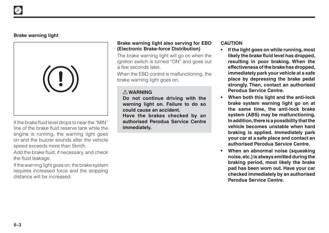
• If the light goes on while running, most likely the brake fluid level has dropped, resulting in poor braking. When the effectiveness of the brake has dropped, immediately park your vehicle at a safe place by depressing the brake pedal strongly. Then, contact an authorised Perodua Service Centre. • When both this light and the anti-lock brake system warning light go on at the same time, the anti-lock brake system (ABS) may be malfunctioning. In addition, there is a possibility that the vehicle becomes unstable when hard braking is applied. Immediately park your car at a safe place and contact an authorised Perodua Service Centre. • When an abnormal noise (squeaking noise, etc.) is always emitted during the braking period, most likely the brake pad has been worn out. Have your car checked immediately by an authorised Perodua Service Centre. If the brake fluid level drops to near the “MIN” line of the brake fluid reserve tank while the engine is running, the warning light goes on and the buzzer sounds after the vehicle speed exceeds more than 5km/h. Add the brake fluid, if necessary, and check the fluid leakage. If the warning light goes on, the brake system requires increased force and the stopping distance will be increased. Brake warning light Brake warning light also serving for EBD (Electronic Brake-force Distribution) The brake warning light will go on when the ignition switch is turned “ON” and goes out a few seconds later. When the EBD control is malfunctioning, the brake warning light goes on. w WARNING Do not continue driving with the warning light on. Failure to do so could cause an accident. Have the brakes checked by an authorised Perodua Service Centre immediately.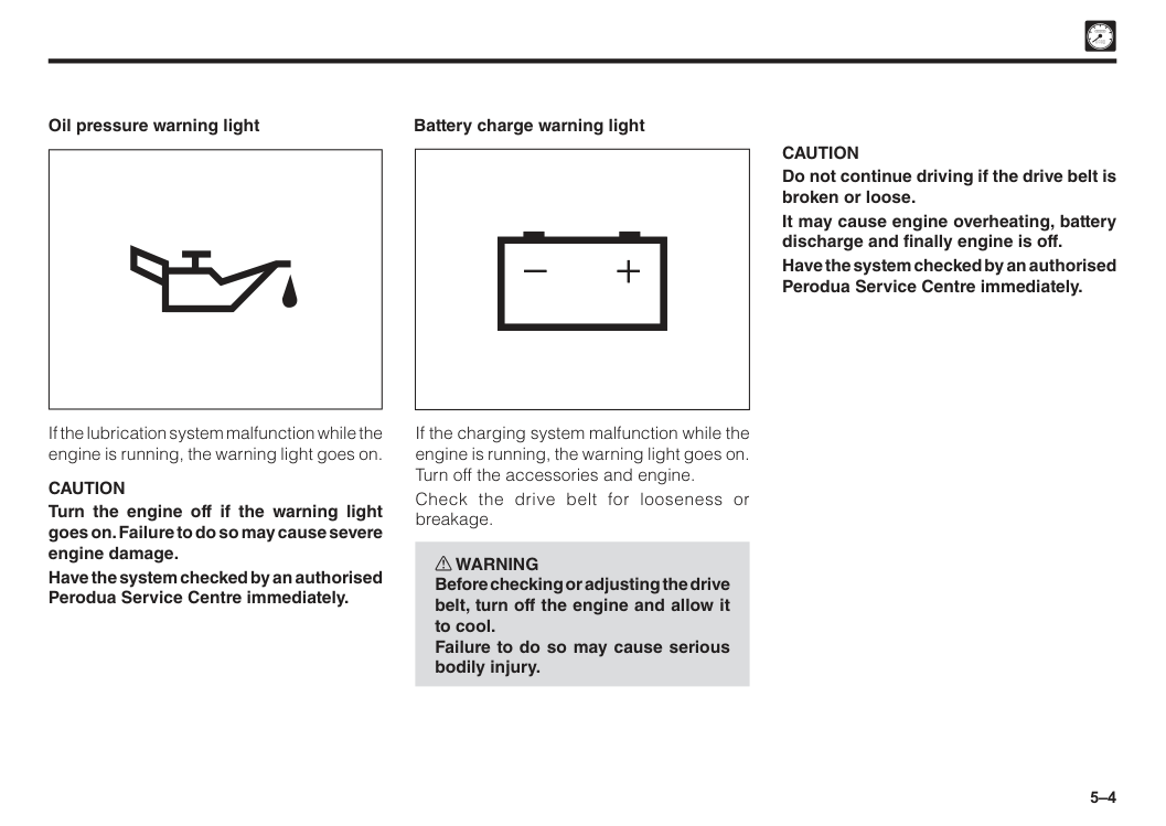
5–4 Battery charge warning light
Caution
Do not continue driving if the drive belt is broken or loose. It may cause engine overheating, battery discharge and finally engine is off. Have the system checked by an authorised Perodua Service Centre immediately. If the charging system malfunction while the engine is running, the warning light goes on. Turn off the accessories and engine. Check the drive belt for looseness or breakage. w WARNING Before checking or adjusting the drive belt, turn off the engine and allow it to cool. Failure to do so may cause serious bodily injury. Oil pressure warning light If the lubrication system malfunction while the engine is running, the warning light goes on.Caution
Turn the engine off if the warning light goes on. Failure to do so may cause severe engine damage. Have the system checked by an authorised Perodua Service Centre immediately.
5–5 ABS (Anti-lock Braking System) warning light This light will go on when the ignition switch is turned “ON” and goes out a few seconds later. The following conditions indicate that the ABS (Anti-lock braking system) is possibly malfunctioning.
Caution
When the ABS warning light and the brake warning light turns on at the same time, the anti-lock brake system may be malfunctioned. In addition, there is a possibility that the vehicle becomes unstable when hard braking is applied. Immediately park your car at a safe place and contact an authorised Perodua Service Centre. Malfunction indicator light (MIL) If the engine electronic control system malfunction while the engine is running, the MIL goes on or blinks.Caution
If the MIL goes on, immediately have the vehicle checked by an authorised Perodua Service Centre.
5–6
At
Automatic transmission warning light goes on if the electronic transmission control (ECAT) should malfunction, either when the engine is running or stopped. This light will go on when the ignition switch is turned “ON” for initial check and go out a few seconds later. w WARNING Do not continue driving when the warning light goes on. Have the system checked by an authorised Perodua Service Centre immediately. Seat belt warning light Driver side If the driver side seat belt is not fastened, the warning light flashes and the buzzer sounds after the vehicle speed exceeds more than 20km/h. Automatic transmission warning lightNote
• Even in cases where the warning light remains illuminated and fails to go out after the engine has started or during the running period, the normal brake performance is retained. (The brake system is no longer functioning as ABS) However, have your car checked by an authorised Perodua Service Centre immediately. • Although the warning light is illuminated for several seconds at the time of the engine starting, the system is functioning normally if the light goes out soon after and does not illuminate afterward while running. • When the engine switch is set to “ON” position, the light turns on for several seconds for the system check and then turns off.
5–7
Caution
When the following conditions appear, have the system checked for these conditions by an authorised Perodua Service Centre immediately. • The warning light does not illuminate immediately after the ignition switch is turned “ON”. • The warning light remains illuminated while the engine is running. • The warning light remains illuminated even if 6 seconds have elapsed after the ignition switch was turned “ON”. • The warning light flashes even if 6 seconds have elapsed after the ignition switch was turned “ON”. Door ajar warning light This light illuminates when any of the doors (including back door) are open or incompletely closed regardless of the position of the ignition switch. The light goes out when all doors have been fully closed.Caution
Do not drive while the light is illuminated. If it is illuminated, it means that door(s) may not be fully closed and may open while driving, causing an unexpected accident. Air bag warning light When any air bag malfunction is detected, the air bag warning light goes on, thereby warning the driver of the malfunction of the system. This light will go on when the ignition switch is turned “ON” for initial check and go out a few second later.
5–8 This light will go on in red colour for 3 seconds when the ignition switch is turned “ON”. Based on the actual engine cooling water temperature, this light will change to blue, remain red or go out. This light flashes when the engine cooling water temperature rises abnormally while the engine is running. The light will go on if the engine cooling water temperature rises further.
Caution
Do not continue driving if the warning light flashes. (See “Engine overheating”). Water temperature warning light In the normal functioning system, the light goes on when the ignition switch is turned “ON”, and then the light goes out when the engine is started. This light goes on when any abnormality is encountered in the power steering with the engine running. The indicator illuminates yellow colour and the buzzer sounds. It shows that the power steering;Note
When you are driving on a hill or turning the vehicle, the fuel moves in the fuel tank. This may turned “ON” the warning light early. In this case, fill up the fuel as soon as possible.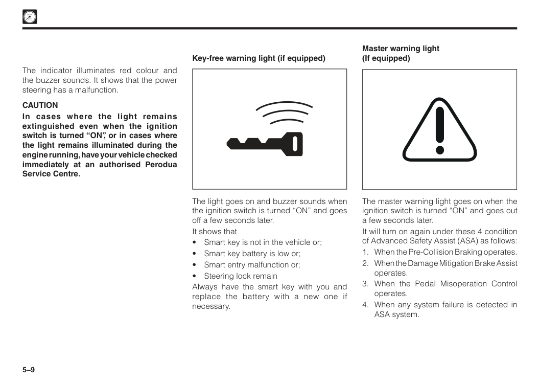
5–9 The light goes on and buzzer sounds when the ignition switch is turned “ON” and goes off a few seconds later. It shows that
Caution
In cases where the light remains extinguished even when the ignition switch is turned “ON”, or in cases where the light remains illuminated during the engine running, have your vehicle checked immediately at an authorised Perodua Service Centre. Master warning light (If equipped) The master warning light goes on when the ignition switch is turned “ON” and goes out a few seconds later. It will turn on again under these 4 condition of Advanced Safety Assist (ASA) as follows: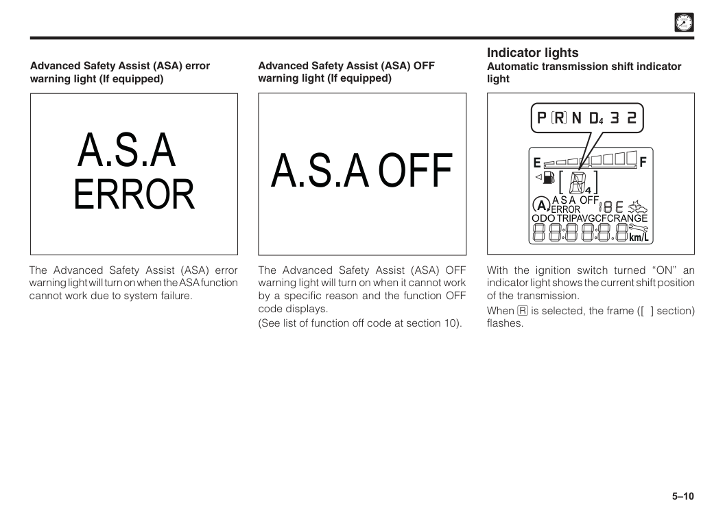
5–10 With the ignition switch turned “ON” an indicator light shows the current shift position of the transmission. When I is selected, the frame ([ ] section) flashes.
A
4F
E
A S A Off
Error
Odo
Range
km/LTripavgcfc
4 Indicator lights Automatic transmission shift indicator light The Advanced Safety Assist (ASA) error warning light will turn on when the ASA function cannot work due to system failure. Advanced Safety Assist (ASA) error warning light (If equipped)A.S.A
Error
A.S.A Off
The Advanced Safety Assist (ASA) OFF warning light will turn on when it cannot work by a specific reason and the function OFF code displays. (See list of function off code at section 10). Advanced Safety Assist (ASA) OFF warning light (If equipped)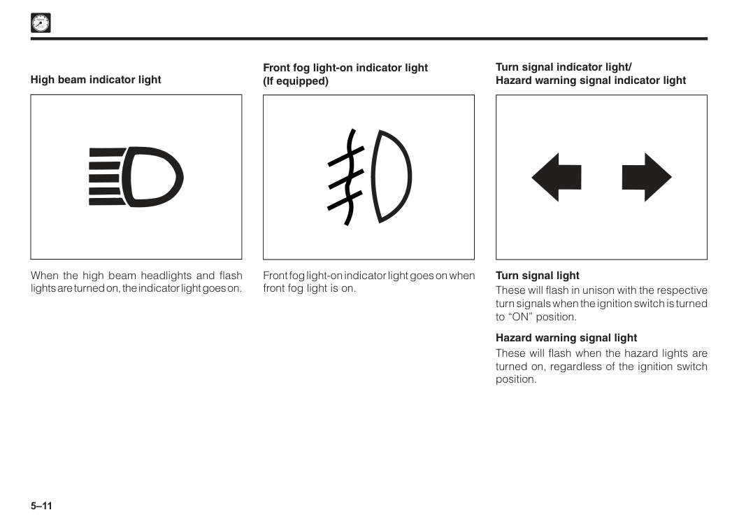
5–11 When the high beam headlights and flash lights are turned on, the indicator light goes on. High beam indicator light Front fog light-on indicator light goes on when front fog light is on. Front fog light-on indicator light (If equipped) Turn signal indicator light/ Hazard warning signal indicator light Turn signal light These will flash in unison with the respective turn signals when the ignition switch is turned to “ON” position. Hazard warning signal light These will flash when the hazard lights are turned on, regardless of the ignition switch position.
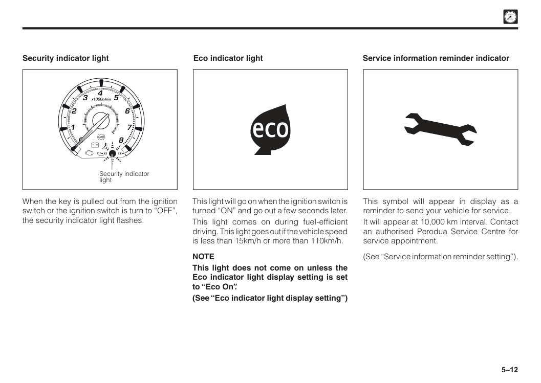
5–12 2 1 0 3 x1000r/min 6 7 8 5 4 Security indicator light Security indicator light When the key is pulled out from the ignition switch or the ignition switch is turn to “OFF”, the security indicator light flashes. Eco indicator light This light will go on when the ignition switch is turned “ON” and go out a few seconds later. This light comes on during fuel-efficient driving. This light goes out if the vehicle speed is less than 15km/h or more than 110km/h.
Note
This light does not come on unless the Eco indicator light display setting is set to “Eco On”. (See “Eco indicator light display setting”) Service information reminder indicator This symbol will appear in display as a reminder to send your vehicle for service. It will appear at 10,000 km interval. Contact an authorised Perodua Service Centre for service appointment. (See “Service information reminder setting”).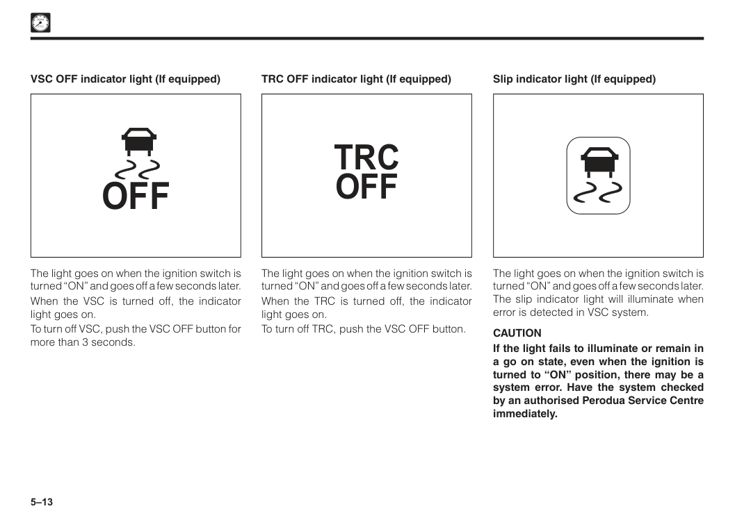
5–13
Off
The light goes on when the ignition switch is turned “ON” and goes off a few seconds later. When the VSC is turned off, the indicator light goes on. To turn off VSC, push the VSC OFF button for more than 3 seconds. VSC OFF indicator light (If equipped)Trc
Off
The light goes on when the ignition switch is turned “ON” and goes off a few seconds later. When the TRC is turned off, the indicator light goes on. To turn off TRC, push the VSC OFF button. TRC OFF indicator light (If equipped) The light goes on when the ignition switch is turned “ON” and goes off a few seconds later. The slip indicator light will illuminate when error is detected in VSC system.Caution
If the light fails to illuminate or remain in a go on state, even when the ignition is turned to “ON” position, there may be a system error. Have the system checked by an authorised Perodua Service Centre immediately. Slip indicator light (If equipped)
5–14
A
Eco Idle ready indicator light (If equipped) This light will go on when the ignition switch is turned “ON” and goes off a few seconds later. This light comes on when the indicator light setting is set to ON and to show that the Eco Idle function is ready. (See “Eco Idle display setting”).Off
A
Eco Idle OFF indicator light (If equipped) This light comes on when the indicator light setting is set to OFF and to show that the Eco Idle display function is OFF. (See “Eco Idle display setting”).Caution
When the system malfunctions is detected, the indicator light goes on or blinks. ASA operation indicator light (If equipped) The ASA operation indicator light goes on when the ignition switch is turned “ON” and goes out a few seconds later. It will blink in Advanced Safety Assist (ASA) function as follows: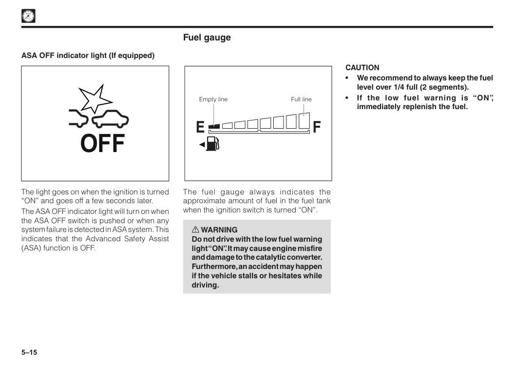
5–15
Caution
• We recommend to always keep the fuel level over 1/4 full (2 segments). • If the low fuel warning is “ON”, immediately replenish the fuel. Full line Empty lineF
E
Fuel gauge The fuel gauge always indicates the approximate amount of fuel in the fuel tank when the ignition switch is turned “ON”. w WARNING Do not drive with the low fuel warning light “ON”. It may cause engine misfire and damage to the catalytic converter. Furthermore, an accident may happen if the vehicle stalls or hesitates while driving. ASA OFF indicator light (If equipped) The light goes on when the ignition is turned “ON” and goes off a few seconds later. The ASA OFF indicator light will turn on when the ASA OFF switch is pushed or when any system failure is detected in ASA system. This indicates that the Advanced Safety Assist (ASA) function is OFF.Off
5–16
F
E
km/LA
4A S A Off
Error
Odo
Range
Tripavgcfc
ecoAt
Off
Trc
Off
Off
P
Off
A
A
4F
E
! 2 1 0 0 20 40 60 80 100 120 140 160 180 200 3 x1000r/min km/hOdo/Trip Disp
Odo
Range
6 7 8 5 4 km/LTripavgcfc
Reset buttonF
E
km/LA
4A S A Off
Error
Odo
Range
Tripavgcfc
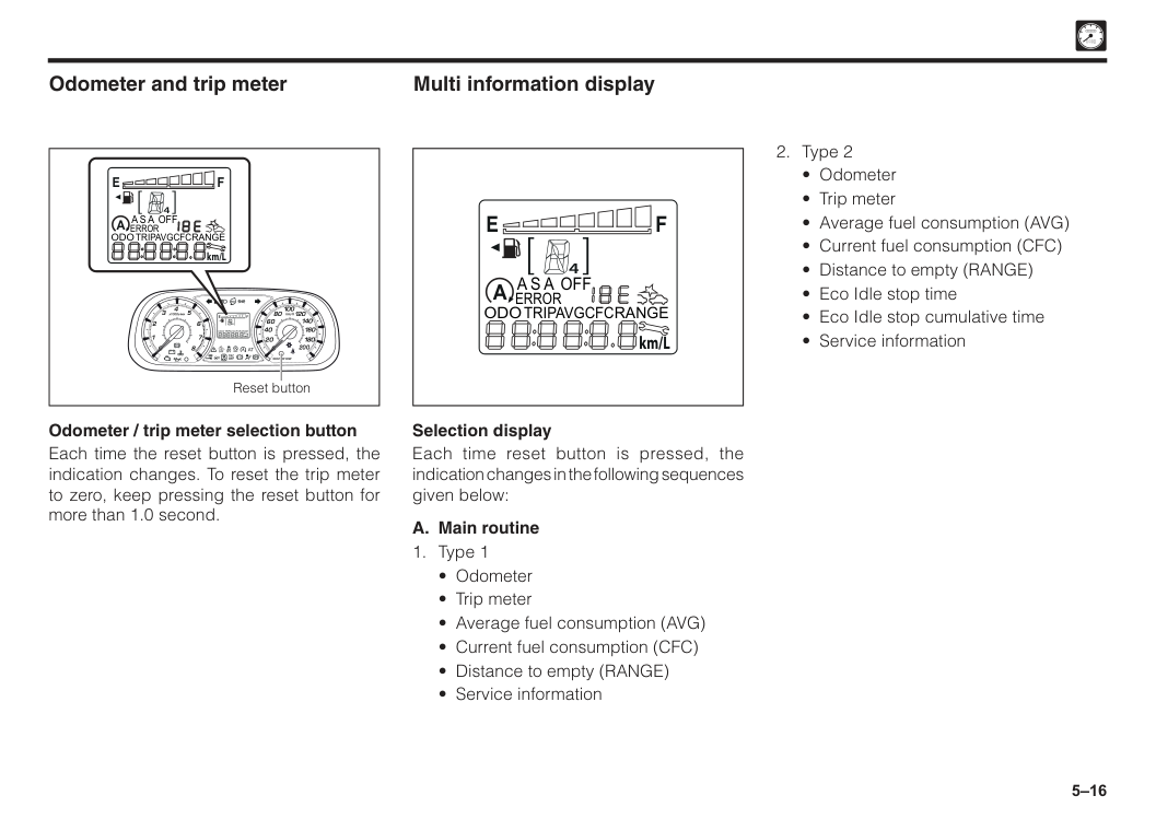
Odometer and trip meter Odometer / trip meter selection button Each time the reset button is pressed, the indication changes. To reset the trip meter to zero, keep pressing the reset button for more than 1.0 second.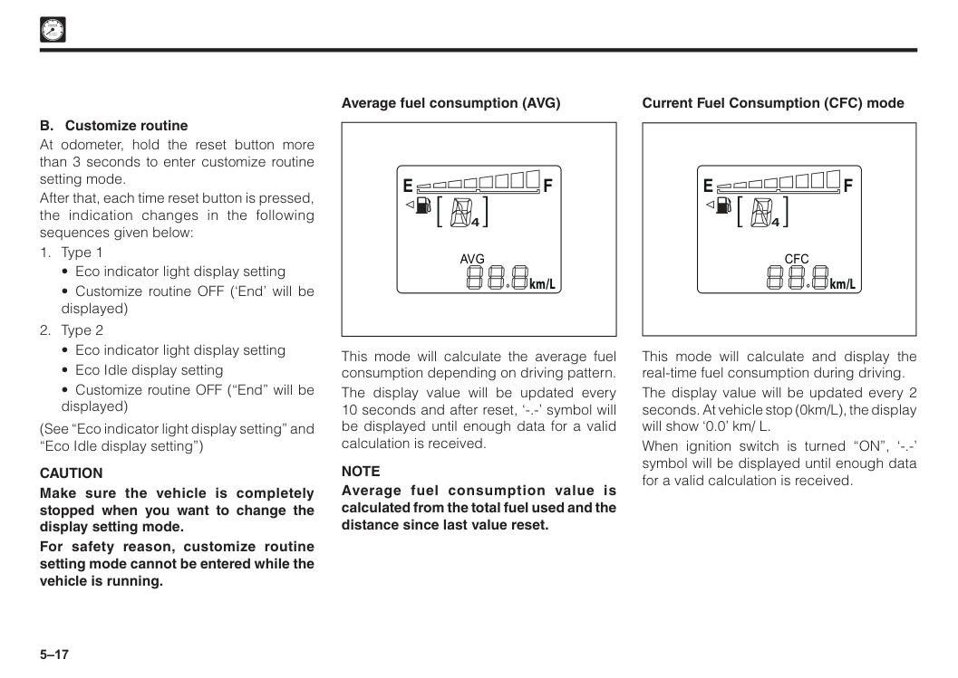
5–17 4
F
E
km/LCfc
Current Fuel Consumption (CFC) mode This mode will calculate and display the real-time fuel consumption during driving. The display value will be updated every 2 seconds. At vehicle stop (0km/L), the display will show ‘0.0’ km/ L. When ignition switch is turned “ON”, ‘-.-’ symbol will be displayed until enough data for a valid calculation is received. 4F
E
km/LAvg
Average fuel consumption (AVG) This mode will calculate the average fuel consumption depending on driving pattern. The display value will be updated every 10 seconds and after reset, ‘-.-’ symbol will be displayed until enough data for a valid calculation is received.Note
Average fuel consumption value is calculated from the total fuel used and the distance since last value reset. B. Customize routine At odometer, hold the reset button more than 3 seconds to enter customize routine setting mode. After that, each time reset button is pressed, the indication changes in the following sequences given below:Caution
Make sure the vehicle is completely stopped when you want to change the display setting mode. For safety reason, customize routine setting mode cannot be entered while the vehicle is running.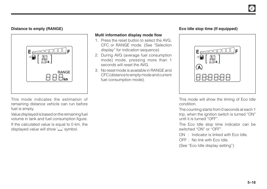
5–18
A
4F
E
Eco Idle stop time (If equipped) This mode will show the timing of Eco Idle condition. The counting starts from 0 seconds at each 1 trip, when the ignition switch is turned “ON” until it is turned “OFF”. The Eco Idle stop time indicator can be switched “ON” or “OFF”. ON : Indicator is linked with Eco Idle. OFF : No link with Eco Idle. (See “Eco Idle display setting”) Multi information display mode flowF
E
Range
km Distance to empty (RANGE) This mode indicates the estimation of remaining distance vehicle can run before fuel is empty. Value displayed is based on the remaining fuel volume in tank and fuel consumption figure. If the calculated value is equal to 0 km, the displayed value will show ‘ ’ symbol.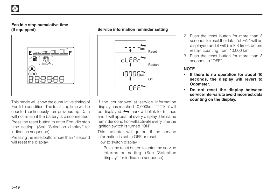
5–19
Note
• If there is no operation for about 10 seconds, the display will revert to Odometer. • Do not reset the display between service intervals to avoid incorrect data counting on the display. If the countdown at service information display has reached 10,000km, ‘ km’ will be displayed. mark will blink for 5 times and it will appear at every display. The same reminder condition will activate every time the ignition switch is turned “ON”. This indicator will go out if the service information is set to OFF or reset. How to switch displayA
4F
E
Odo
Eco Idle stop cumulative time (If equipped) This mode will show the cumulative timing of Eco Idle condition. The total stop time will be counted continuously from previous trip. Data will not retain if the battery is disconnected. Press the reset button to enter Eco Idle stop time setting. (See “Selection display” for indication sequence). Pressing the reset button more than 1 second will reset the display.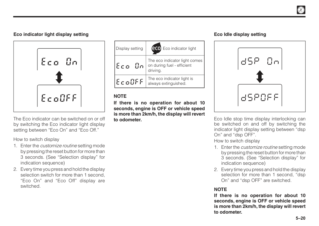
5–20 Eco Idle display setting Eco Idle stop time display interlocking can be switched on and off by switching the indicator light display setting between “dsp On” and “dsp OFF”. How to switch display
Note
If there is no operation for about 10 seconds, engine is OFF or vehicle speed is more than 2km/h, the display will revert to odometer. Display setting Eco indicator light The eco indicator light comes on during fuel - efficient driving. The eco indicator light is always extinguished.Note
If there is no operation for about 10 seconds, engine is OFF or vehicle speed is more than 2km/h, the display will revert to odometer. The Eco indicator can be switched on or off by switching the Eco indicator light display setting between “Eco On” and “Eco Off.” How to switch display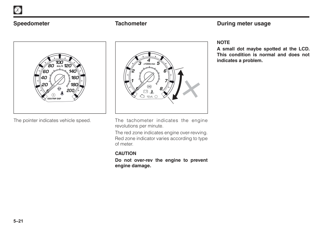
5–21 During meter usage
Note
A small dot maybe spotted at the LCD. This condition is normal and does not indicates a problem. 2 1 0 3 x1000r/min 6 7 8 5 4 The tachometer indicates the engine revolutions per minute. The red zone indicates engine over-revving. Red zone indicator varies according to type of meter.Caution
Do not over-rev the engine to prevent engine damage. Tachometer 0 20 40 60 80 100 120 140 160 180 200 km/hOdo/Trip Disp
Speedometer The pointer indicates vehicle speed.
6 Air conditioner..................................................................................6–1 Section 6 Air conditioner control systems
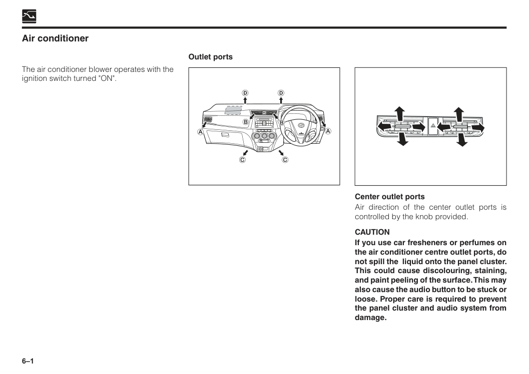
6–1 Air conditioner Outlet ports The air conditioner blower operates with the ignition switch turned "ON". Center outlet ports Air direction of the center outlet ports is controlled by the knob provided.
Caution
If you use car fresheners or perfumes on the air conditioner centre outlet ports, do not spill the liquid onto the panel cluster. This could cause discolouring, staining, and paint peeling of the surface. This may also cause the audio button to be stuck or loose. Proper care is required to prevent the panel cluster and audio system from damage.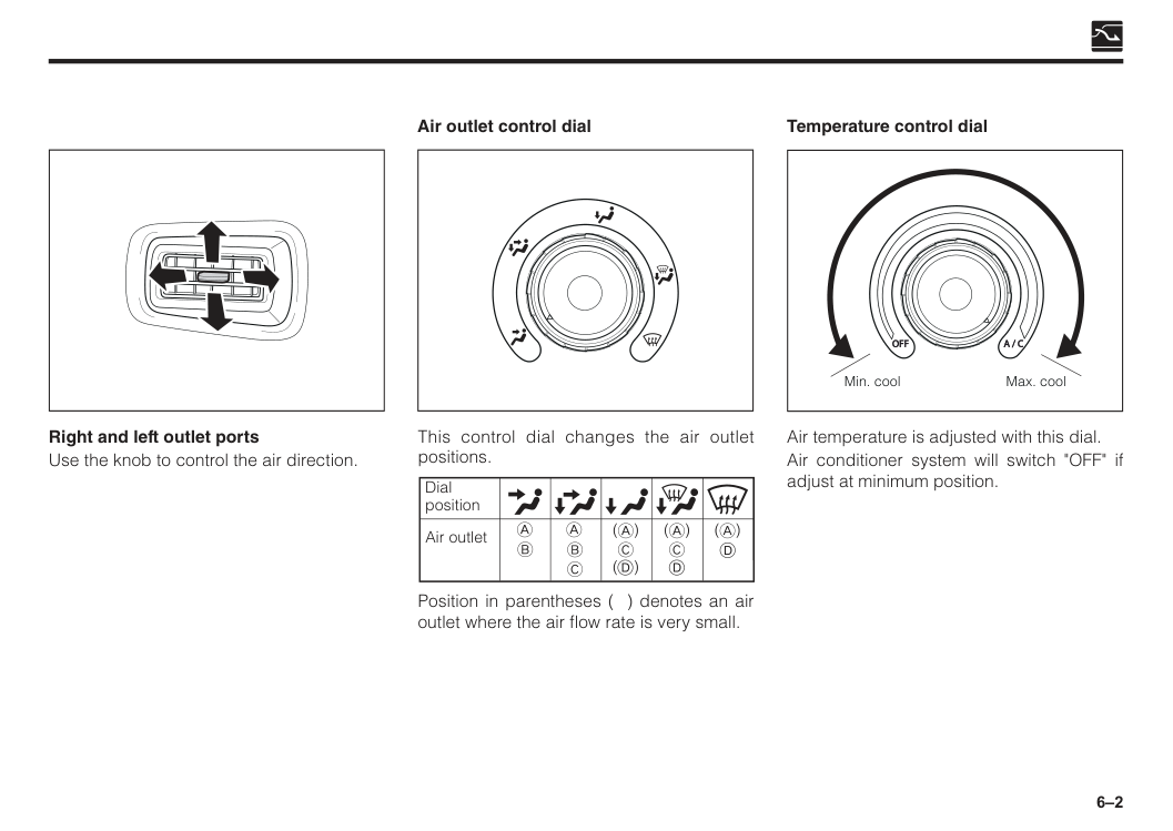
6–2 Right and left outlet ports Use the knob to control the air direction. This control dial changes the air outlet positions. Dial position Air outlet
D
Position in parentheses ( ) denotes an air outlet where the air flow rate is very small. Air outlet control dial Temperature control dial Air temperature is adjusted with this dial. Air conditioner system will switch "OFF" if adjust at minimum position.A / C
Off
Min. cool Max. cool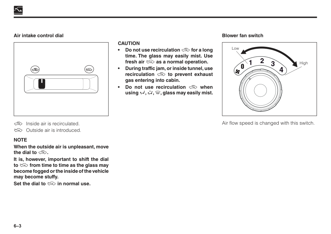
6–3 \ Inside air is recirculated. ] Outside air is introduced.
Note
When the outside air is unpleasant, move the dial to \. It is, however, important to shift the dial to ] from time to time as the glass may become fogged or the inside of the vehicle may become stuffy. Set the dial to ] in normal use. Air intake control dialCaution
• Do not use recirculation \ for a long time. The glass may easily mist. Use fresh air ] as a normal operation. • During traffic jam, or inside tunnel, use recirculation \ to prevent exhaust gas entering into cabin. • Do not use recirculation \ when using Y, Z, [, glass may easily mist. Air flow speed is changed with this switch. Blower fan switch Low High 0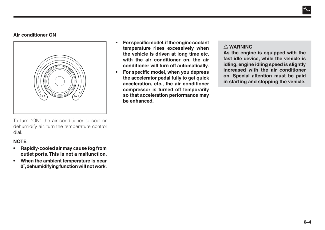
6–4 To turn “ON” the air conditioner to cool or dehumidify air, turn the temperature control dial.
Note
• Rapidly-cooled air may cause fog from outlet ports. This is not a malfunction. • When the ambient temperature is near 0˚, dehumidifying function will not work. Air conditioner ONA / C
Off
• For specific model, if the engine coolant temperature rises excessively when the vehicle is driven at long time etc. with the air conditioner on, the air conditioner will turn off automatically. • For specific model, when you depress the accelerator pedal fully to get quick acceleration, etc., the air conditioner compressor is turned off temporarily so that acceleration performance may be enhanced. w WARNING As the engine is equipped with the fast idle device, while the vehicle is idling, engine idling speed is slightly increased with the air conditioner on. Special attention must be paid in starting and stopping the vehicle.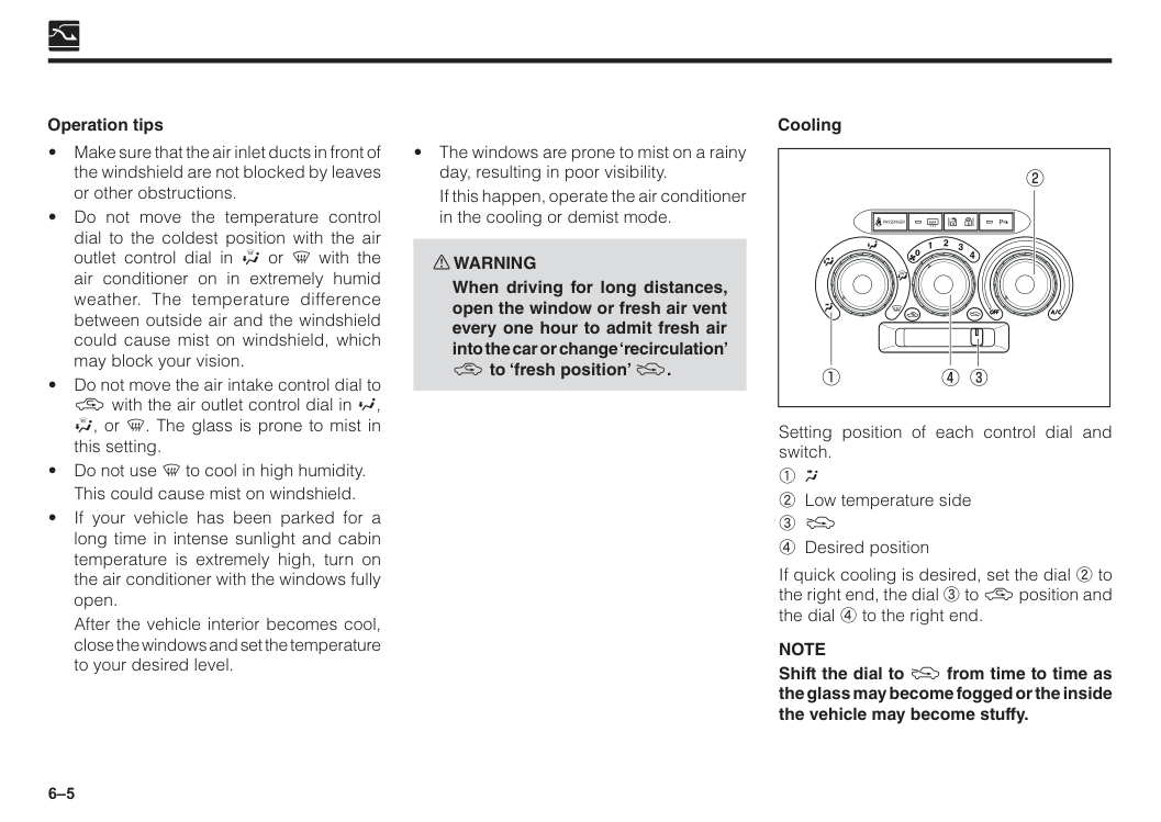
6–5 Operation tips
If this happen, operate the air conditioner in the cooling or demist mode. w WARNING
When driving for long distances, open the window or fresh air vent every one hour to admit fresh air into the car or change ‘recirculation’ \ to ‘fresh position’ ]. Cooling
A / C
Off
0Passenger
P
Setting position of each control dial and switch.1 W
2 Low temperature side 3 ] 4 Desired position If quick cooling is desired, set the dial 2 to the right end, the dial 3 to \ position and the dial 4 to the right end.Note
Shift the dial to ] from time to time as the glass may become fogged or the inside the vehicle may become stuffy.This could cause mist on windshield.
After the vehicle interior becomes cool, close the windows and set the temperature to your desired level.
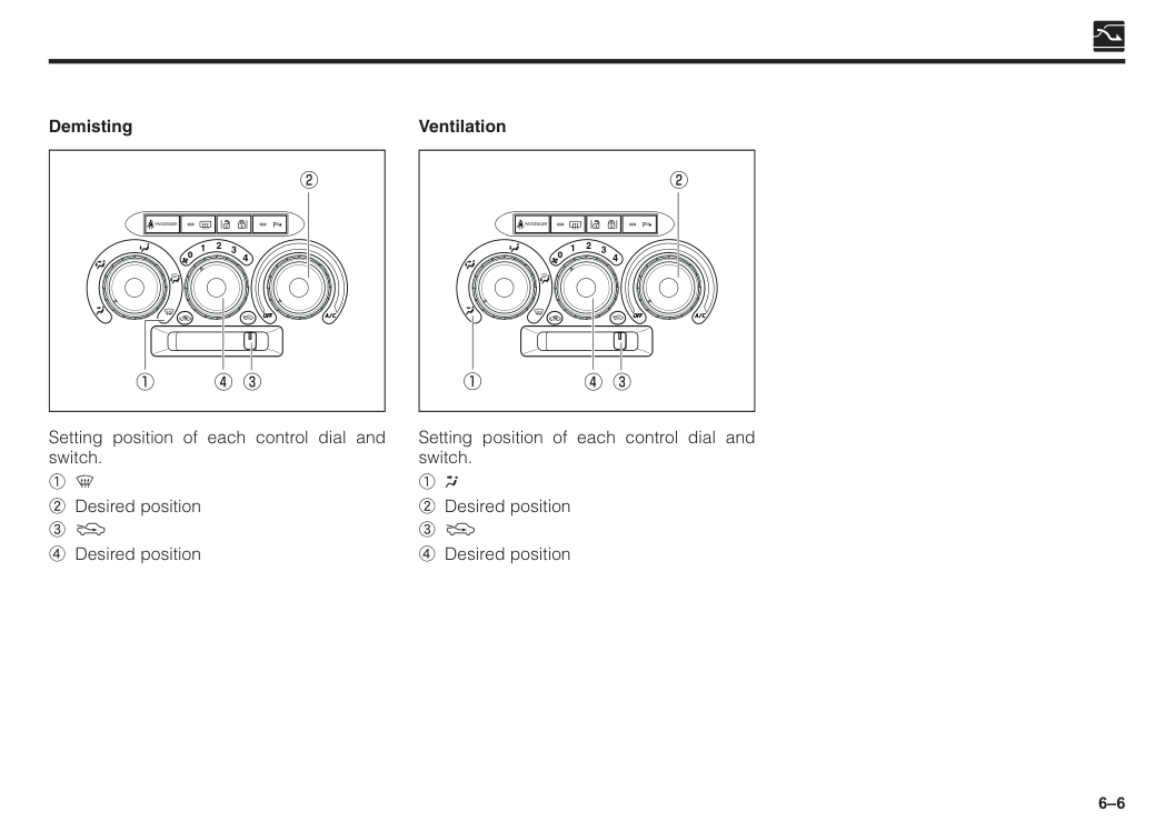
6–6 Demisting
A / C
Off
0Passenger
P
Setting position of each control dial and switch. 1 [ 2 Desired position 3 ] 4 Desired position Setting position of each control dial and switch.1 W
2 Desired position 3 ] 4 Desired position VentilationA / C
Off
0Passenger
P
7 Section 7 Audio systems Features.............................................................................................7–1 General operation.............................................................................7–2 Tuner operation.................................................................................7–5 Playing USB......................................................................................7–7 Bluetooth operation.........................................................................7–10 Installation.........................................................................................7–16 Radio wire connection.....................................................................7–17 Specification.....................................................................................7–18 Antenna.............................................................................................7–19
7–1 Features Tuner
Display
Usb
Bt Music
• Tracks Up/Down
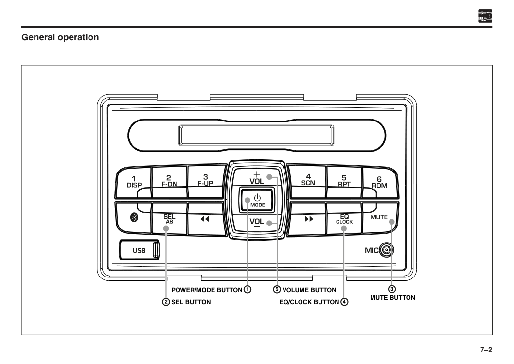
7–2 General operation
Sel Button
Volume Button
Mute Button
Eq/Clock Button
Power/Mode Button
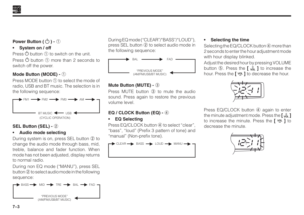
7–3 Power Button ( ) - 1 • System on / off Press button 1 to switch on the unit. Press button 1 more than 2 seconds to switch off the power. Mode Button (MODE) - 1 Press MODE button 1 to select the mode of radio, USB and BT music. The selection is in the following sequence: ►
Bt Music Usb
(Cyclic Operation)
►Fm1
Fm2
►Fm3
► ►Am
► ► SEL Button (SEL) - 2 • Audio mode selecting During system is on, press SEL button 2 to change the audio mode through bass, mid, treble, balance and fader function. When mode has not been adjusted, display returns to normal radio. During non EQ mode (“MANU”), press SEL button 2 to select audio mode in the following sequence: ►“Previous Mode”
(Am/Fm/Usb/Bt Music)
►Bass
Mid
►Tre
►Bal
Fad
► ► During EQ mode (“CLEAR”/“BASS”/“LOUD”), press SEL button 2 to select audio mode in the following sequence: ►“Previous Mode”
(Am/Fm/Usb/Bt Music)
►Bal
Fad
► Mute Button (MUTE) - 3 Press MUTE button 3 to mute the audio sound. Press again to restore the previous volume level. EQ / CLOCK Button (EQ) - 4 • EQ Selecting Press EQ/CLOCK button 4 to select “clear”, “bass”, “loud” (Prefix 3 pattern of tone) and “manual” (Non-prefix tone). ► ►Clear
Bass
►Loud
►Manu
► • Selecting the time Selecting the EQ/CLOCK button 4 more than 2 seconds to enter the hour adjustment mode with hour display blinked. Adjust the desired hour by pressing VOLUME button 5. Press the [ ] to increase the hour. Press the [ ] to decrease the hour. Press EQ/CLOCK button 4 again to enter the minute adjustment mode. Press the [ ] to increase the minute. Press the [ ] to decrease the minute.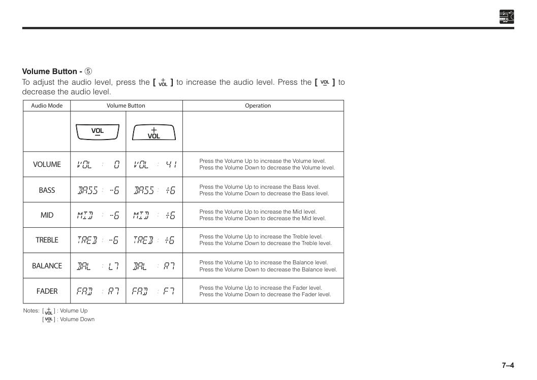
7–4 Volume Button - 5 To adjust the audio level, press the [ ] to increase the audio level. Press the [ ] to decrease the audio level. Press the Volume Up to increase the Volume level. Press the Volume Down to decrease the Volume level. Press the Volume Up to increase the Bass level. Press the Volume Down to decrease the Bass level. Press the Volume Up to increase the Mid level. Press the Volume Down to decrease the Mid level. Press the Volume Up to increase the Treble level. Press the Volume Down to decrease the Treble level. Press the Volume Up to increase the Balance level. Press the Volume Down to decrease the Balance level. Press the Volume Up to increase the Fader level. Press the Volume Down to decrease the Fader level. Operation Audio Mode Volume Button
Volume
Bass
Mid
Treble
Balance
Fader
Notes: [ ] : Volume Up[ ] : Volume Down
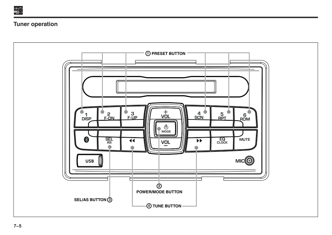
7–5 Tuner operation
Preset Button
Sel/As Button
Power/Mode Button
Tune Button
7–6 Preset Button (1 to 6) - 1 These buttons are used for preset station function in tuner mode. With this system, a total of 24 stations can be stored in the memory 6 each for the FM 1, FM 2, FM 3 and AM. • Presetting Station Tune in the desired station manually or automatically and press button (1 to 6) at which you want to store that station for more than 2 seconds. • Calling Up Station After your favourite stations are preset at button 1 to 6, simply press buttons 1 to 6 to call up the stations in the preset memory. Power/Mode Button (MODE) - 2 • Band Selecting Press POWER/MODE button 2 to select the band of FM1, FM2, FM3 & AM. SEL/AS Button (AS) - 3 • Auto Storing Press SEL/AS button 3 more than 2 seconds to auto store 6 strongest stations in the preset memory button 1 to 6 at FM3 band. Tune Button ( / ) - 4 • Manual Tuning Press the tune button 4 in tuner mode to tune the frequency up or down manually. • Auto Tuning Press the tune button 4 more than 1 second in tuner mode to auto tune the frequency up or down.
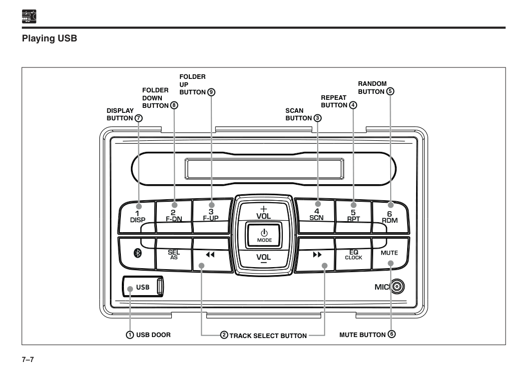
7–7 Playing USB
Folder
Up
Button
Scan
Button
Repeat
Button
Random
Button
Folder
Down
Button
Display
Button
Mute Button
Usb Door
Track Select Button
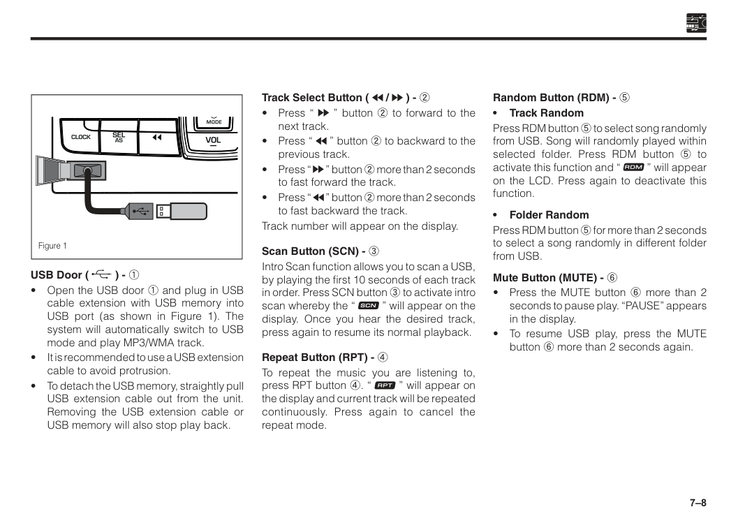
7–8 Track Select Button ( / ) - 2
7–9
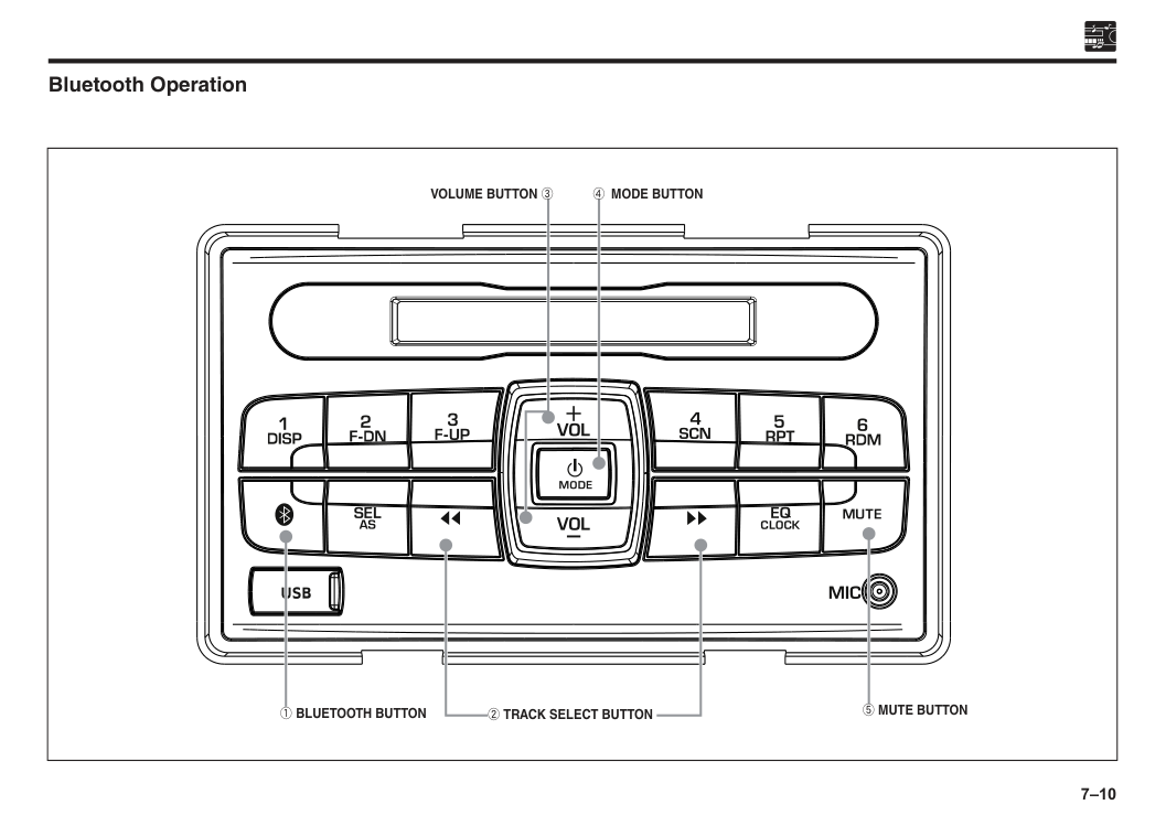
7–10 Bluetooth Operation
1 Bluetooth Button
2 Track Select Button
5 Mute Button
Volume Button 3
4 Mode Button
7–11 Bluetooth button ( ) - 1 BT menu adjustment selecting Press the Bluetooth button 1 to select telephone menu adjustment in the following sequence:
Add Dev
Manu Ans
Bt Reset
“Previous Mode” (Am/Fm/Usb/Bt Music)
Add Dev
Bluetooth handsfree Step 1: Enter into pairing mode (discoverable and connectable mode)To enable pairing mode:
a. Car audio system
b. The Audio System displays “PAIRING” and Bluetooth logo ( ) will flashes on LCD, indicates that the Bluetooth is now ready to be paired with the mobile phone.
c. Mobile phone
For devices which do not support Simple Secured Pairing (SSP), the device will prompt the user to enter a passkey. Enter the PIN: “0000” when requested.
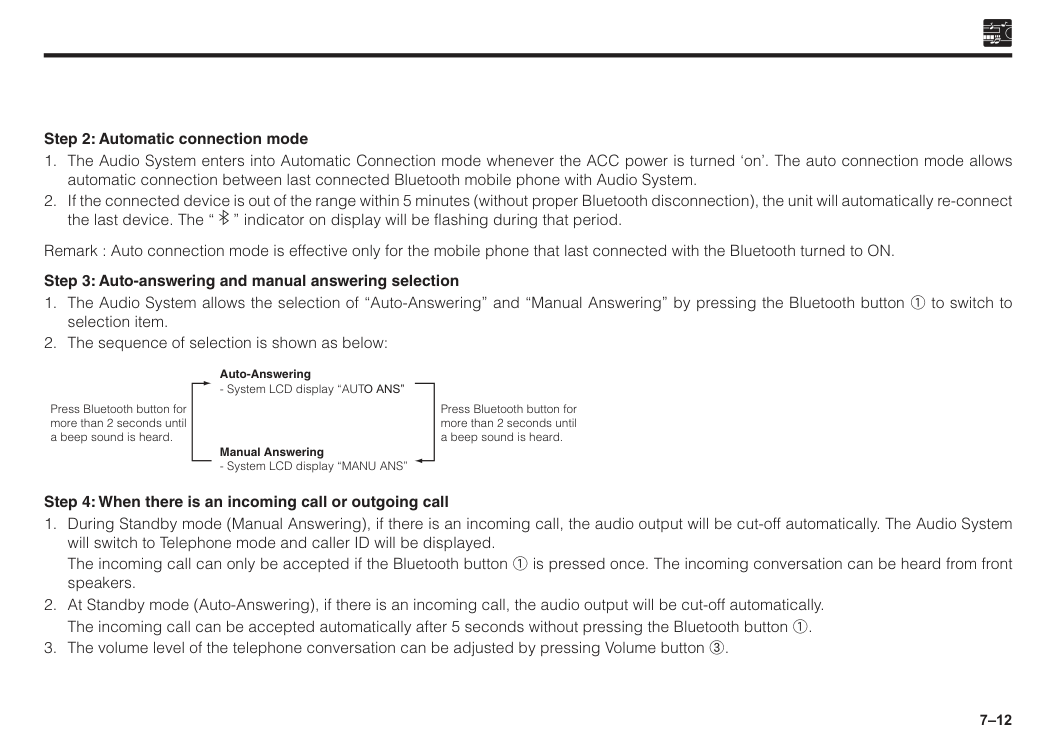
7–12 Step 2: Automatic connection mode
The incoming call can only be accepted if the Bluetooth button 1 is pressed once. The incoming conversation can be heard from front speakers.
The incoming call can be accepted automatically after 5 seconds without pressing the Bluetooth button 1.
7–13 Step 5: Ending a call
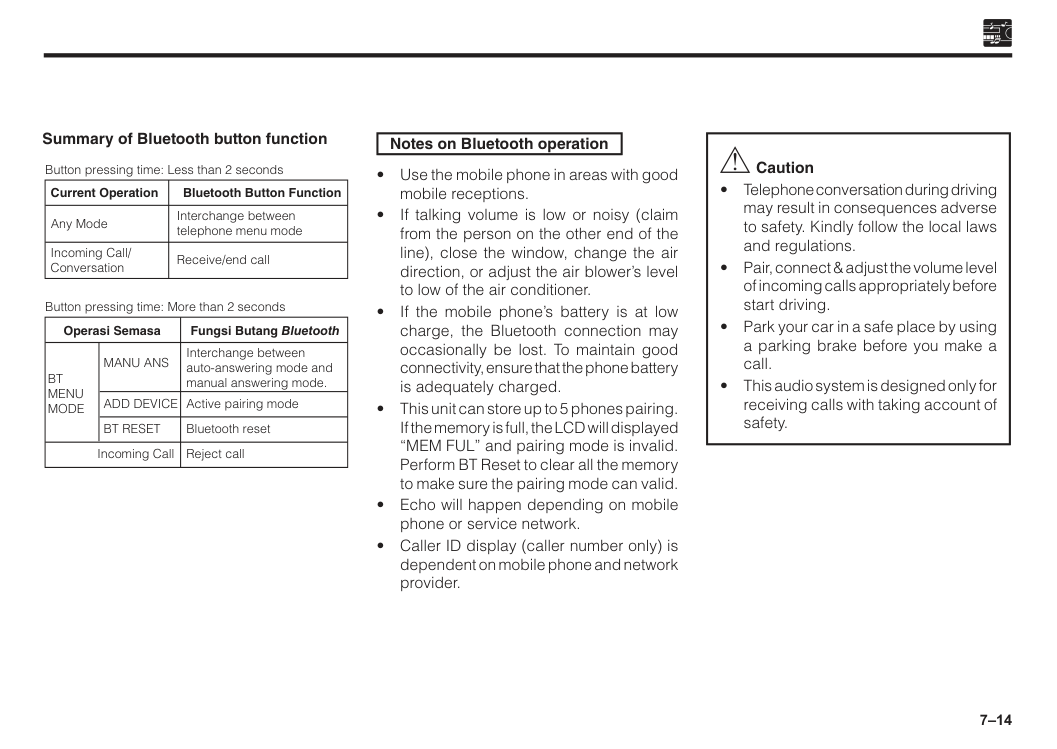
7–14 Summary of Bluetooth button function Interchange between auto-answering mode and manual answering mode. Active pairing mode Bluetooth reset Reject call Button pressing time: Less than 2 seconds Current Operation Incoming Call/ Conversation Any Mode Bluetooth Button Function Interchange between telephone menu mode Receive/end call Button pressing time: More than 2 seconds Operasi Semasa
Add Device
Manu Ans
Bt
Menu
Mode
Incoming CallBt Reset
Fungsi Butang Bluetooth Notes on Bluetooth operation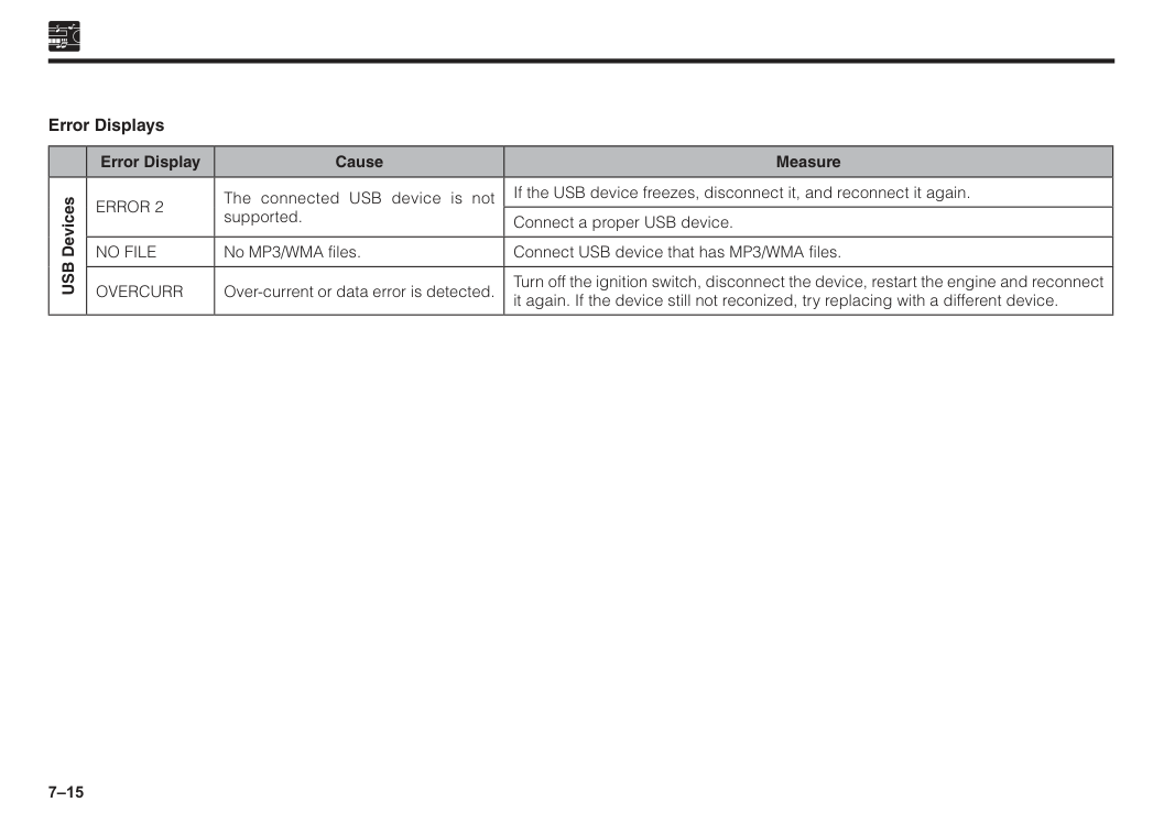
7–15 Error Displays Error Display Cause Measure USB Devices
Error 2
The connected USB device is not supported. If the USB device freezes, disconnect it, and reconnect it again. Connect a proper USB device.No File
No MP3/WMA files. Connect USB device that has MP3/WMA files.Overcurr
Over-current or data error is detected. Turn off the ignition switch, disconnect the device, restart the engine and reconnect it again. If the device still not reconized, try replacing with a different device.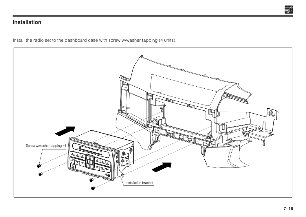
7–16 Installation Install the radio set to the dashboard case with screw w/washer tapping (4 units). Screw w/washer tapping x4 Installation bracket
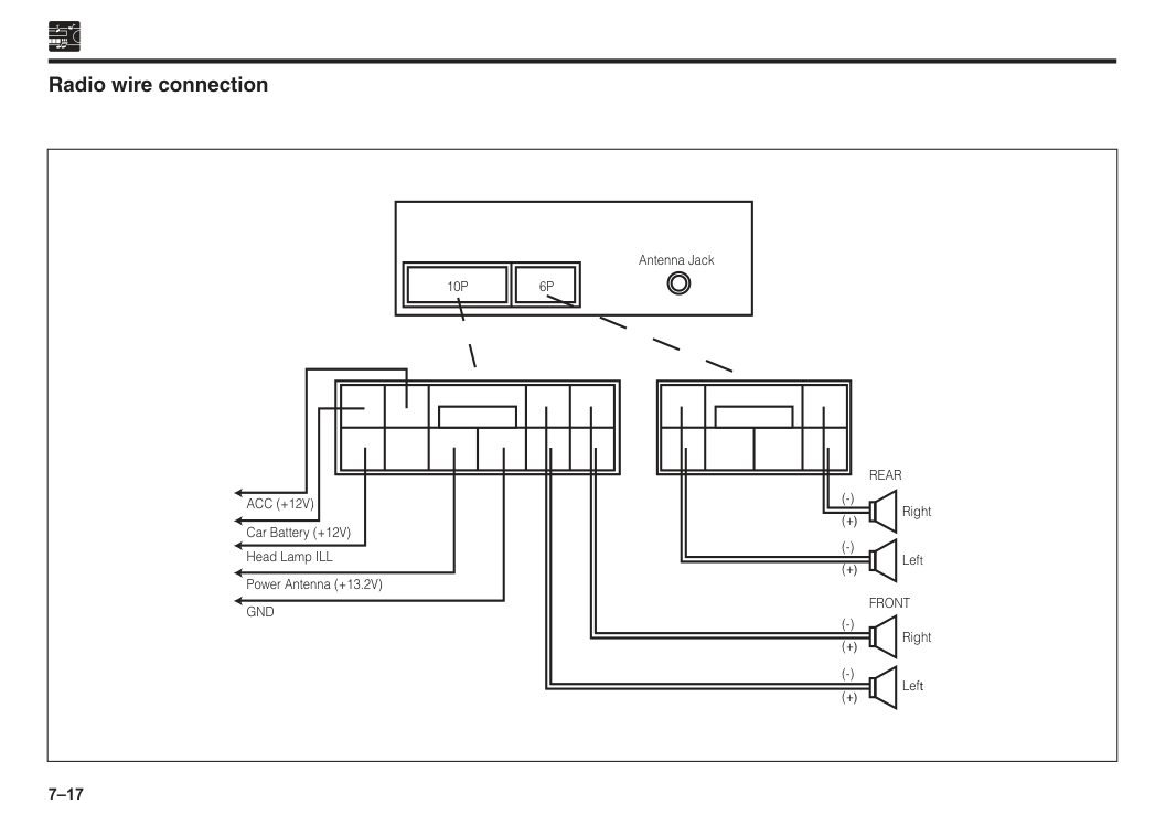
7–17
10P
Front
Rear
(-) (+) (-) (+) (-) (+) (-) (+) Right Left Right Left Antenna Jack6P
Acc (+12V)
Car Battery (+12V) Head Lamp ILL Power Antenna (+13.2V)Gnd
Radio wire connection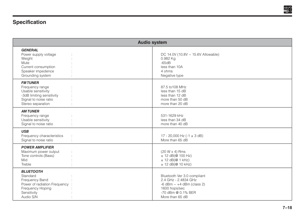
7–18 Specification Audio system
General
Power supply voltage : Weight : Mute : Current consumption : Speaker impedence : Grounding system : DC 14.0V (10.8V ~ 15.6V Allowable) 0.982 Kg -65dB less than 10A 4 ohms Negative typeFm Tuner
Frequency range : Usable sensitivity : -3dB limiting sensitivity : Signal to noise ratio : Stereo separation : 87.5 to108 MHz less than 15 dB less than 12 dB more than 50 dB more than 20 dBAm Tuner
Frequency range : Usable sensitivity : Signal to noise ratio : 531-1629 kHz less than 34 dB more than 40 dBUsb
Frequency characteristics : Signal to noise ratio : 17 - 20,000 Hz (-1 ± 3 dB) More than 65 dBPower Amplifier
Maximum power output : Tone controls (Bass) : Mid : Treble : (20 W x 4) Rms ± 12 dB(@ 100 Hz) ± 12 dB(@ 1 kHz) ± 12 dB(@ 10 kHz)Bluetooth
Standard : Frequency Band : Power of radiation Frequency : Frequency Hoping : Sensitivity : Audio S/N : Bluetooth Ver 3.0 compliant 2.4 GHz - 2.4834 GHz -6 dBm ~ +4 dBm (class 2) 1600 hops/sec -70 dBm @ 0.1% BER More than 65 dB
7–19 Antenna Shark fin type If there is a problem with your antenna, please consult with an authorised Perodua Service Centre.

8 Side mirrors......................................................................................8–1 Inside mirror......................................................................................8–2 Section 8 Mirrors
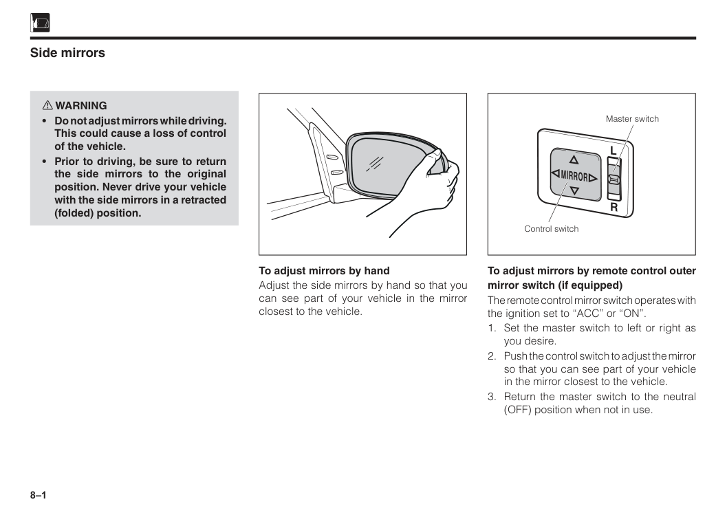
8–1 Master switch Control switch
L
R
Mirror
Side mirrors w WARNING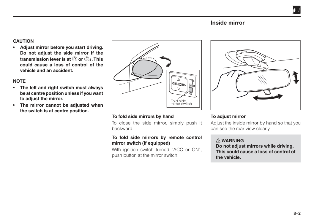
8–2
Caution
• Adjust mirror before you start driving. Do not adjust the side mirror if the transmission lever is at R or D4 .This could cause a loss of control of the vehicle and an accident.Note
• The left and right switch must always be at centre position unless if you want to adjust the mirror. • The mirror cannot be adjusted when the switch is at centre position. To fold side mirrors by hand To close the side mirror, simply push it backward. To fold side mirrors by remote control mirror switch (if equipped) With ignition switch turned “ACC or ON”, push button at the mirror switch. Fold side mirror switchL
R
Mirror
Inside mirror To adjust mirror Adjust the inside mirror by hand so that you can see the rear view clearly. w WARNING Do not adjust mirrors while driving. This could cause a loss of control of the vehicle.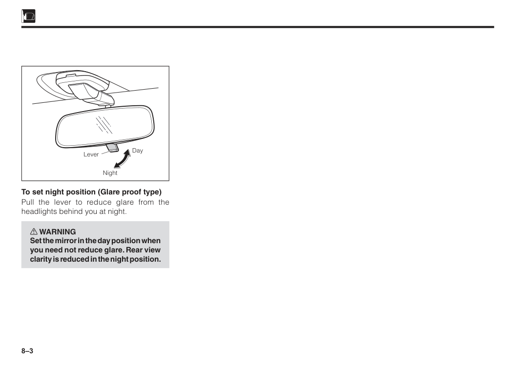
8–3 Lever Day Night To set night position (Glare proof type) Pull the lever to reduce glare from the headlights behind you at night. w WARNING Set the mirror in the day position when you need not reduce glare. Rear view clarity is reduced in the night position.
9 Interior lights.....................................................................................9–1 Horn...................................................................................................9–1 Assist grip.........................................................................................9–1 Sun visor...........................................................................................9–2 Glove box..........................................................................................9–3 Utility box..........................................................................................9–3 Mobile phone compartment............................................................9–4 Bottle holder.....................................................................................9–4 Shopping hook.................................................................................9–5 Anti snatch hook..............................................................................9–5 Seatback pocket...............................................................................9–6 Section 9 Interior equipment
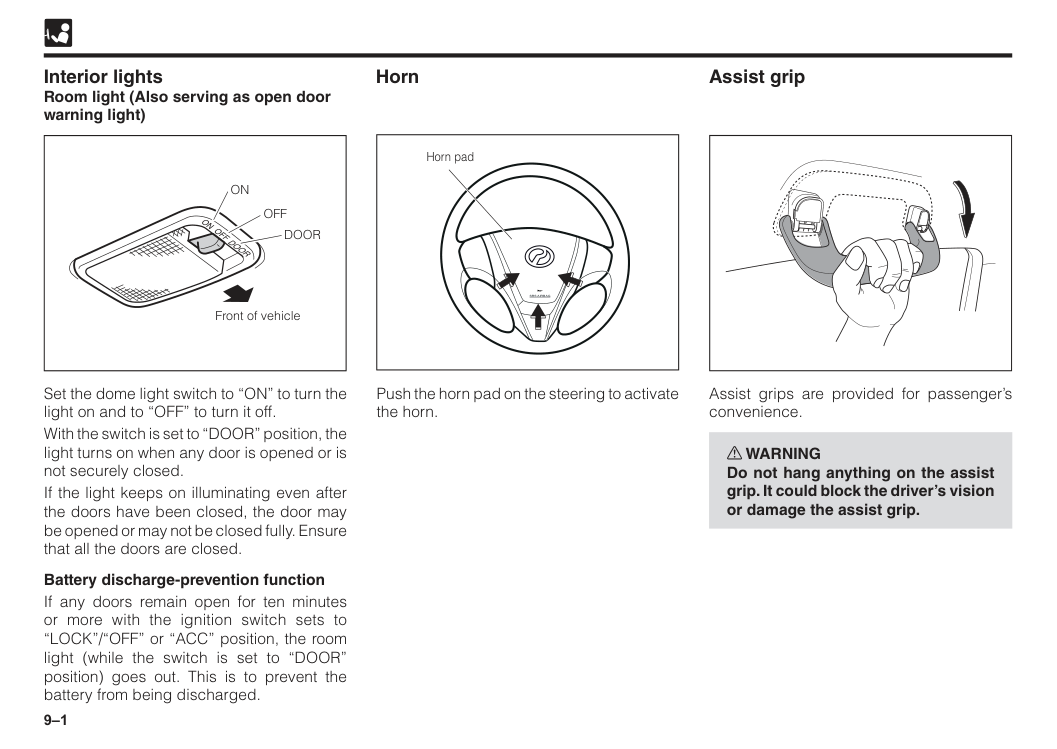
9–1
Off
Door
On
Front of vehicle Interior lights Room light (Also serving as open door warning light) Set the dome light switch to “ON” to turn the light on and to “OFF” to turn it off. With the switch is set to “DOOR” position, the light turns on when any door is opened or is not securely closed. If the light keeps on illuminating even after the doors have been closed, the door may be opened or may not be closed fully. Ensure that all the doors are closed. Battery discharge-prevention function If any doors remain open for ten minutes or more with the ignition switch sets to “LOCK”/“OFF” or “ACC” position, the room light (while the switch is set to “DOOR” position) goes out. This is to prevent the battery from being discharged.Srs Airbag
Horn pad Push the horn pad on the steering to activate the horn. Horn Assist grip Assist grips are provided for passenger’s convenience. w WARNING Do not hang anything on the assist grip. It could block the driver’s vision or damage the assist grip.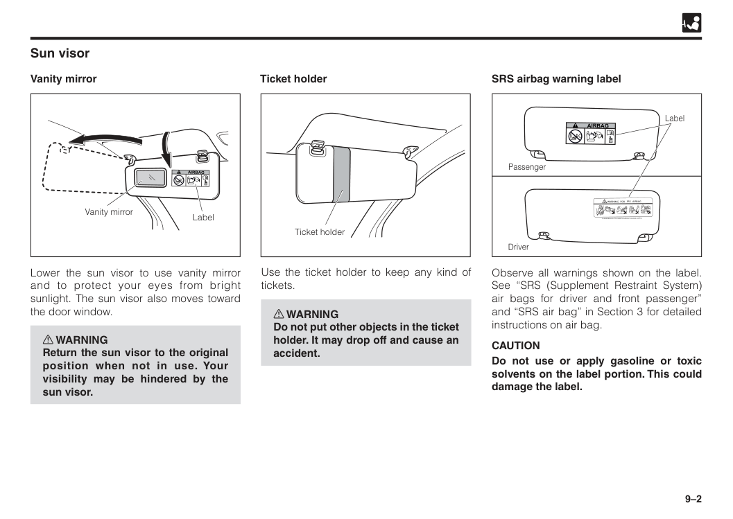
9–2 Lower the sun visor to use vanity mirror and to protect your eyes from bright sunlight. The sun visor also moves toward the door window. w WARNING Return the sun visor to the original position when not in use. Your visibility may be hindered by the sun visor. Sun visor Vanity mirror
Airbag
Vanity mirror Label Ticket holder Ticket holder Use the ticket holder to keep any kind of tickets. w WARNING Do not put other objects in the ticket holder. It may drop off and cause an accident. SRS airbag warning labelWarning For Srs Airbag
Please Refer To The Owner’S Manual For More Details
Driver Passenger LabelAirbag
Observe all warnings shown on the label. See “SRS (Supplement Restraint System) air bags for driver and front passenger” and “SRS air bag” in Section 3 for detailed instructions on air bag.Caution
Do not use or apply gasoline or toxic solvents on the label portion. This could damage the label.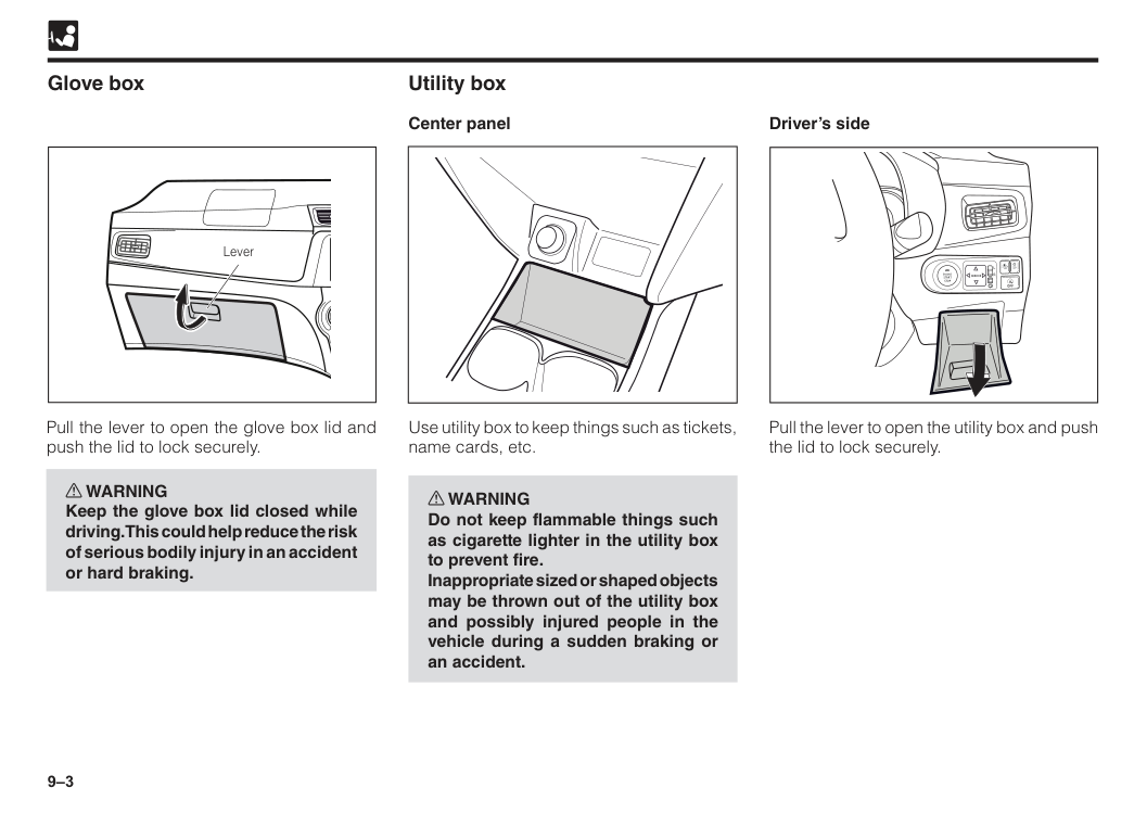
9–3 Glove box Pull the lever to open the glove box lid and push the lid to lock securely. w WARNING Keep the glove box lid closed while driving. This could help reduce the risk of serious bodily injury in an accident or hard braking. Lever Utility box Center panel Use utility box to keep things such as tickets, name cards, etc. w WARNING Do not keep flammable things such as cigarette lighter in the utility box to prevent fire. Inappropriate sized or shaped objects may be thrown out of the utility box and possibly injured people in the vehicle during a sudden braking or an accident.
R
L
Mirror
Engine
Start
Stop
Off
Off
Off
A
Driver’s side Pull the lever to open the utility box and push the lid to lock securely.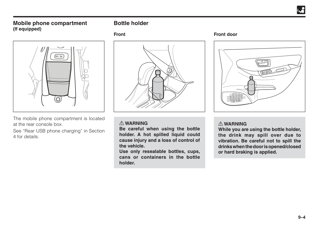
9–4 Bottle holder Front Mobile phone compartment (If equipped) w WARNING Be careful when using the bottle holder. A hot spilled liquid could cause injury and a loss of control of the vehicle. Use only resealable bottles, cups, cans or containers in the bottle holder. The mobile phone compartment is located at the rear console box. See “Rear USB phone charging” in Section 4 for details. Front door w WARNING While you are using the bottle holder, the drink may spill over due to vibration. Be careful not to spill the drinks when the door is opened/closed or hard braking is applied.
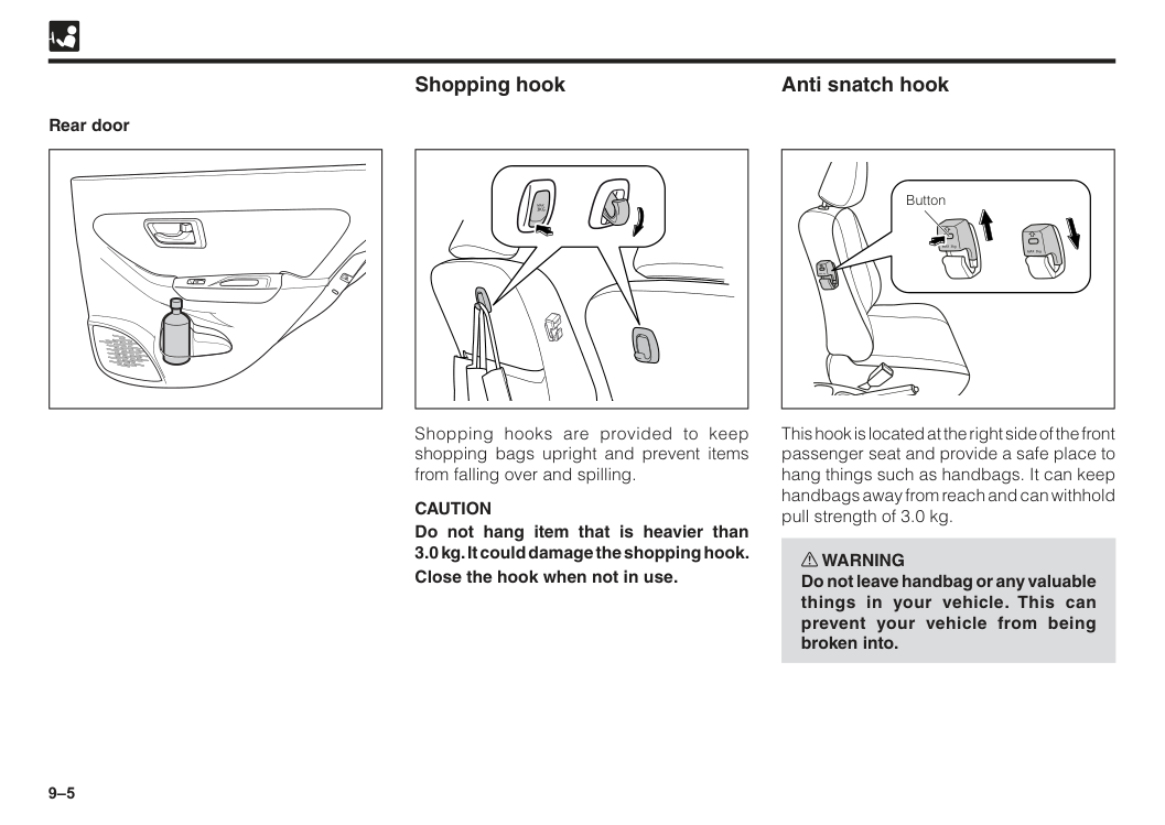
9–5 Rear door Shopping hook Anti snatch hook Shopping hooks are provided to keep shopping bags upright and prevent items from falling over and spilling.
Caution
Do not hang item that is heavier than 3.0 kg. It could damage the shopping hook. Close the hook when not in use.Max
3Kg
This hook is located at the right side of the front passenger seat and provide a safe place to hang things such as handbags. It can keep handbags away from reach and can withhold pull strength of 3.0 kg. w WARNING Do not leave handbag or any valuable things in your vehicle. This can prevent your vehicle from being broken into. MAX 3kg MAX 3kg MAX 3kg Button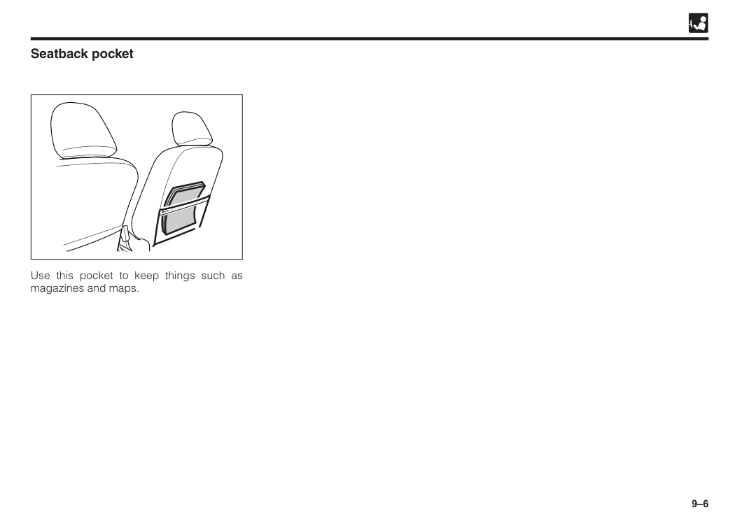
9–6 Seatback pocket Use this pocket to keep things such as magazines and maps.
10 Before starting engine.....................................................................10–1 Starting engine.................................................................................10–1 Manual transmission shifting instructions....................................10–2 Shifting points (Manual transmission)...........................................10–3 Automatic transmission shifting instructions...............................10–4 Normal driving tips...........................................................................10–9 Economical driving tips...................................................................10–9 Brake system....................................................................................10–9 Brake pad wear limit indicator.........................................................10–11 Parking tips.......................................................................................10–12 Parking brake warning buzzer.........................................................10–14 Power steering..................................................................................10–14 Eco Idle system.................................................................................10–14 VSC (Vehicle stability control) • TRC (Traction control)................10–20 Hill-Start Assist.................................................................................10–22 ESS (Emergency Stop Signal).........................................................10–24 ASA (Advanced Safety Assist) 2.0..................................................10–24 Section 10 Driving tips
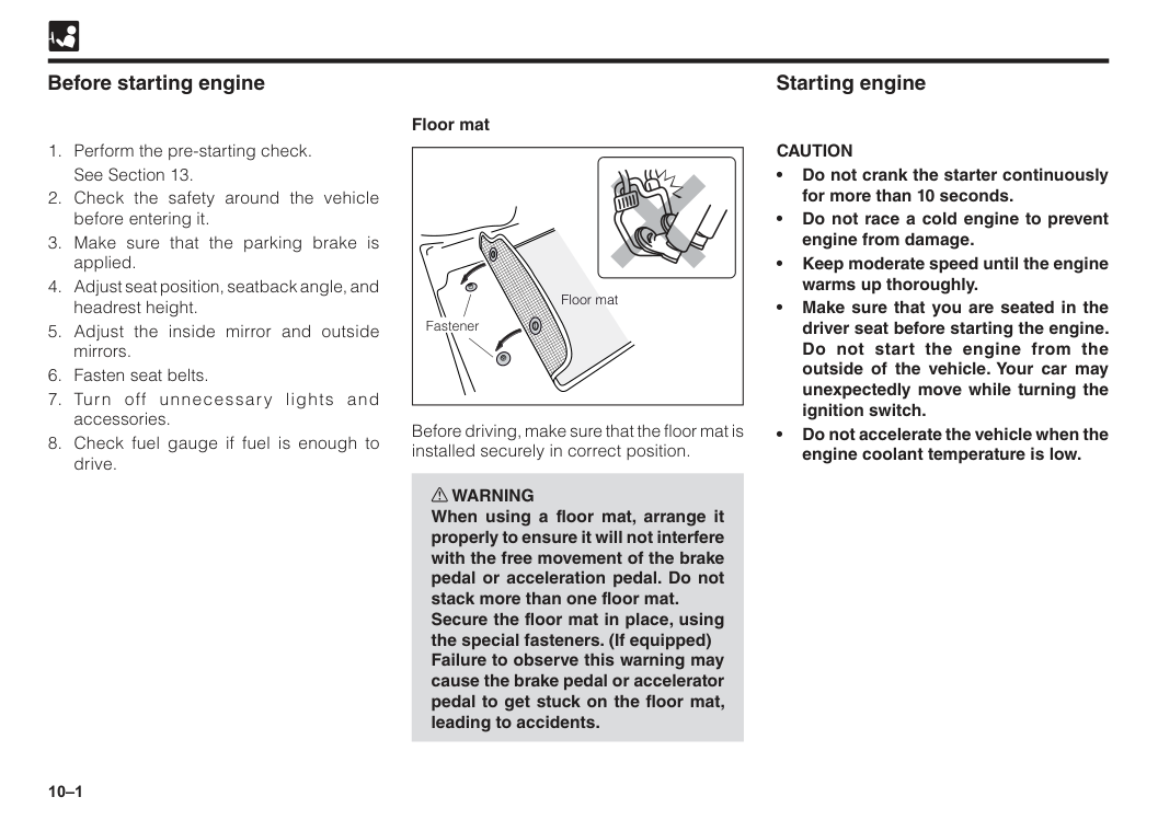
10–1 Before starting engine
See Section 13.
Caution
• Do not crank the starter continuously for more than 10 seconds. • Do not race a cold engine to prevent engine from damage. • Keep moderate speed until the engine warms up thoroughly. • Make sure that you are seated in the driver seat before starting the engine. Do not start the engine from the outside of the vehicle. Your car may unexpectedly move while turning the ignition switch. • Do not accelerate the vehicle when the engine coolant temperature is low. Floor mat Fastener Floor mat Before driving, make sure that the floor mat is installed securely in correct position. w WARNING When using a floor mat, arrange it properly to ensure it will not interfere with the free movement of the brake pedal or acceleration pedal. Do not stack more than one floor mat. Secure the floor mat in place, using the special fasteners. (If equipped) Failure to observe this warning may cause the brake pedal or accelerator pedal to get stuck on the floor mat, leading to accidents.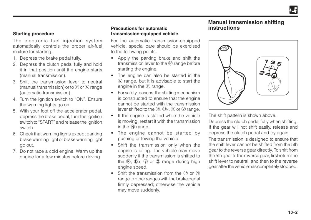
10–2 For the automatic transmission-equipped vehicle, special care should be exercised to the following points.
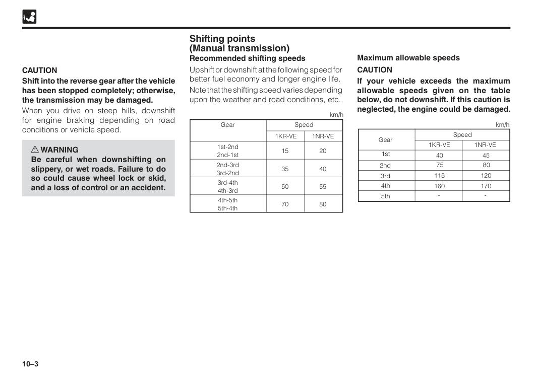
10–3 Shifting points (Manual transmission) Recommended shifting speeds Upshift or downshift at the following speed for better fuel economy and longer engine life. Note that the shifting speed varies depending upon the weather and road conditions, etc. Gear 1st-2nd 2nd-1st 15 35 50 70 20 40 55 80 2nd-3rd 3rd-2nd 3rd-4th 4th-3rd 4th-5th 5th-4th Speed
1Kr-Ve
1Nr-Ve
km/hCaution
Shift into the reverse gear after the vehicle has been stopped completely; otherwise, the transmission may be damaged. When you drive on steep hills, downshift for engine braking depending on road conditions or vehicle speed. w WARNING Be careful when downshifting on slippery, or wet roads. Failure to do so could cause wheel lock or skid, and a loss of control or an accident.Caution
If your vehicle exceeds the maximum allowable speeds given on the table below, do not downshift. If this caution is neglected, the engine could be damaged. Speed 401Kr-Ve
1Nr-Ve
km/h 1st 2nd 3rd 4th 5th 75 115 160 45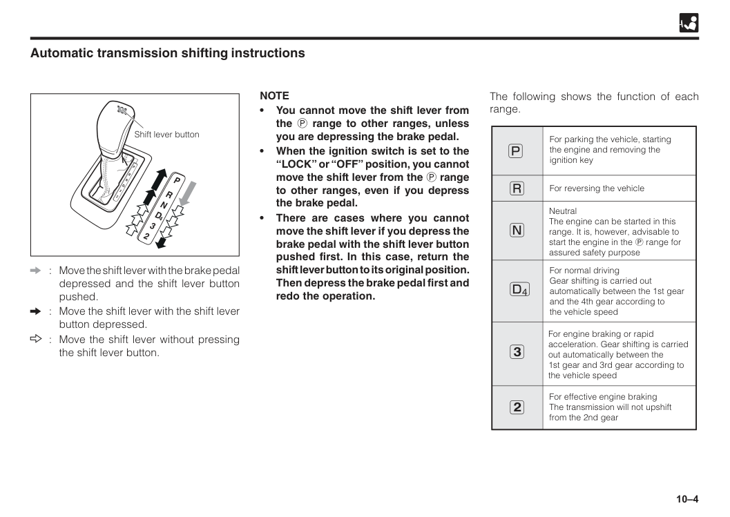
10–4 Shift lever button Automatic transmission shifting instructions : Move the shift lever with the brake pedal depressed and the shift lever button pushed. : Move the shift lever with the shift lever button depressed. : Move the shift lever without pressing the shift lever button.
Note
• You cannot move the shift lever from the P range to other ranges, unless you are depressing the brake pedal. • When the ignition switch is set to the “LOCK” or “OFF” position, you cannot move the shift lever from the P range to other ranges, even if you depress the brake pedal. • There are cases where you cannot move the shift lever if you depress the brake pedal with the shift lever button pushed first. In this case, return the shift lever button to its original position. Then depress the brake pedal first and redo the operation. The following shows the function of each range. For parking the vehicle, starting the engine and removing the ignition key For reversing the vehicle Neutral The engine can be started in this range. It is, however, advisable to start the engine in the P range for assured safety purpose For normal driving Gear shifting is carried out automatically between the 1st gear and the 4th gear according to the vehicle speed For engine braking or rapid acceleration. Gear shifting is carried out automatically between the 1st gear and 3rd gear according to the vehicle speed For effective engine braking The transmission will not upshift from the 2nd gear 3 2 4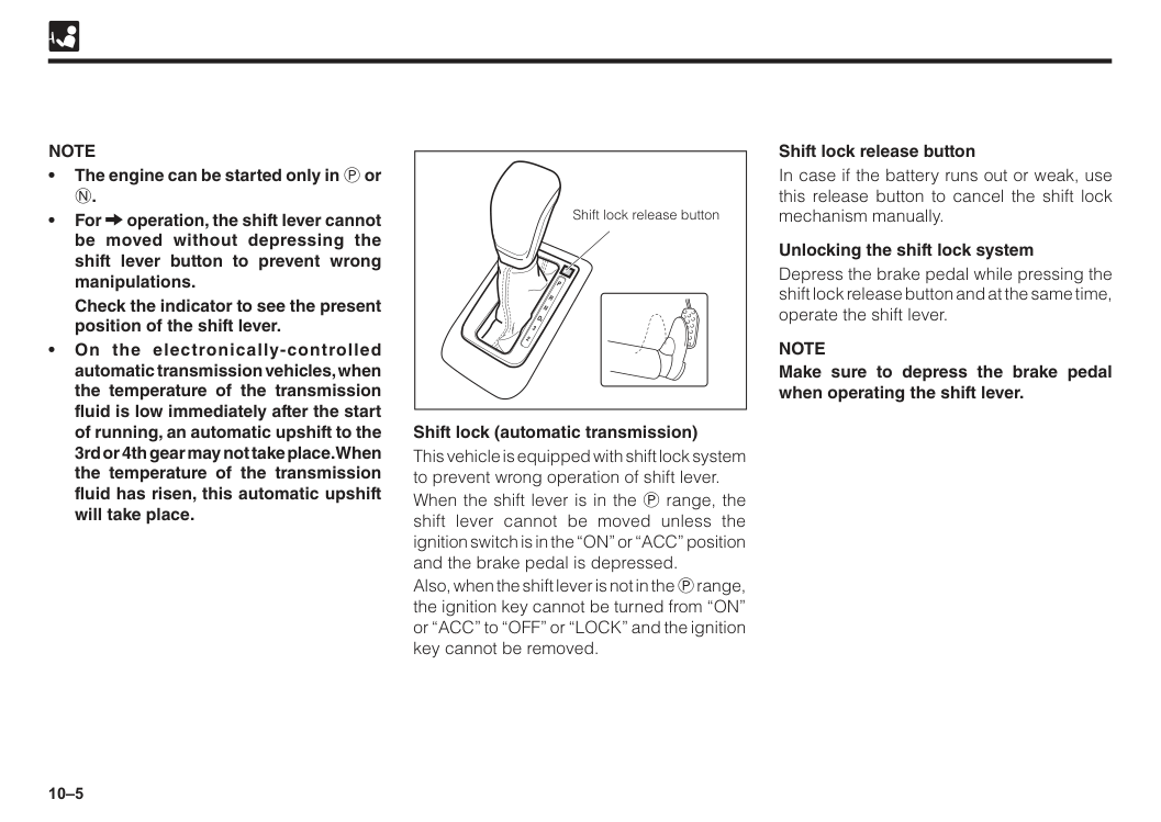
10–5 Shift lock release button Shift lock (automatic transmission) This vehicle is equipped with shift lock system to prevent wrong operation of shift lever. When the shift lever is in the P range, the shift lever cannot be moved unless the ignition switch is in the “ON” or “ACC” position and the brake pedal is depressed. Also, when the shift lever is not in the P range, the ignition key cannot be turned from “ON” or “ACC” to “OFF” or “LOCK” and the ignition key cannot be removed.
Note
• The engine can be started only in P orN.
• For operation, the shift lever cannot be moved without depressing the shift lever button to prevent wrong manipulations.Check the indicator to see the present position of the shift lever. • On the electronically-controlled automatic transmission vehicles, when the temperature of the transmission fluid is low immediately after the start of running, an automatic upshift to the 3rd or 4th gear may not take place. When the temperature of the transmission fluid has risen, this automatic upshift will take place. Shift lock release button In case if the battery runs out or weak, use this release button to cancel the shift lock mechanism manually. Unlocking the shift lock system Depress the brake pedal while pressing the shift lock release button and at the same time, operate the shift lever.
Note
Make sure to depress the brake pedal when operating the shift lever.
10–6 While depressing the brake pedal firmly, place the shift lever to the desired position in D4 (or 3 or 2) for forward driving or in R for backward driving. After releasing the parking brake completely, move the vehicle by releasing the brake pedal slowly. w WARNING
operation, move the shift lever without pressing the shift lever button in order to avoid wrong operation. If the shift lever button is always pressed during the operation, the shift lever may be inadvertently placed in P, R or 2 range, resulting in an unexpected accident.
Even if the shift lever is in D4, the transmission will downshift automatically to the 3rd gear or the 2nd gear depending on vehicle speed.
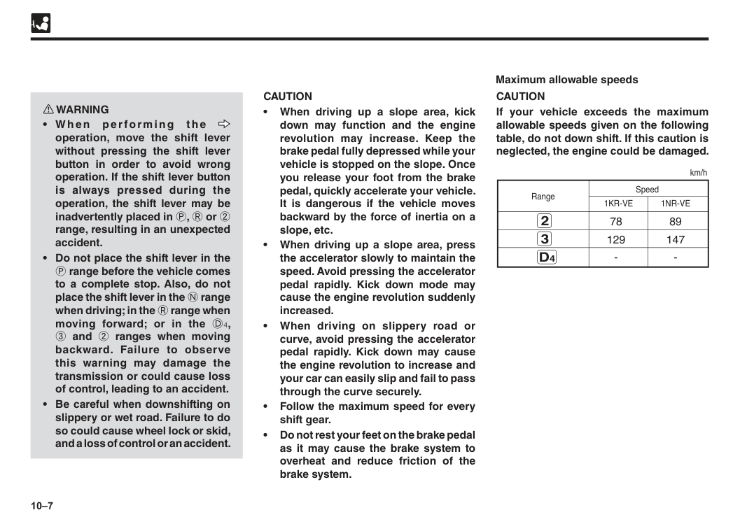
10–7
Caution
• When driving up a slope area, kick down may function and the engine revolution may increase. Keep the brake pedal fully depressed while your vehicle is stopped on the slope. Once you release your foot from the brake pedal, quickly accelerate your vehicle. It is dangerous if the vehicle moves backward by the force of inertia on a slope, etc. • When driving up a slope area, press the accelerator slowly to maintain the speed. Avoid pressing the accelerator pedal rapidly. Kick down mode may cause the engine revolution suddenly increased. • When driving on slippery road or curve, avoid pressing the accelerator pedal rapidly. Kick down may cause the engine revolution to increase and your car can easily slip and fail to pass through the curve securely. • Follow the maximum speed for every shift gear. • Do not rest your feet on the brake pedal as it may cause the brake system to overheat and reduce friction of the brake system. w WARNINGoperation, move the shift lever without pressing the shift lever button in order to avoid wrong operation. If the shift lever button is always pressed during the operation, the shift lever may be inadvertently placed in P, R or 2 range, resulting in an unexpected accident.
Caution
If your vehicle exceeds the maximum allowable speeds given on the following table, do not down shift. If this caution is neglected, the engine could be damaged. 78 89 129 1471Kr-Ve
1Nr-Ve
Range km/h 3D4
2 Maximum allowable speeds
10–8 After the vehicle has completely stopped, apply the parking brake and shift the transmission lever to P while depressing the brake pedal. w WARNING
Caution
• Be careful with your driving posture while reversing your car. Make sure with that posture you still manage to control the brake. • After reverse, make sure that you turn back the lever to N or P. • Make sure that your car has completely stopped before shifting the lever from D4 to R and from R to D4. Press the brake pedal firmly. Failure to follow this instruction may damage the transmission system. Reverse
10–9 Economical driving tips
Caution
• Do not rest your foot on the clutch pedal while driving, or do not hold your vehicle with the clutch while stopping on an upgrade. This could cause clutch overheating. • Do not drive with the shift lever in neutral. This could cause transmission overheating. • Do not rest your hand on the shift lever knob while driving. The transmission could accidentally be shifted into another range. Also, this could cause transmission damage. • Do not race the engine when shifting. This could cause engine overheating. • Do not drive through water if the water depth is higher than the bottom of the wheel rims. Drive slowly when driving through water. Your Perodua is equipped with a tandem master cylinder brake system. Each brake system functions independently. If either of the brake system fails, the other system still works. However, the brake system requires increased force and the stopping distance will be increased. Furthermore, the brake warning light should go on. w WARNING Do not continue driving with the malfunctioning brake system. Have the system checked immediately. Brake system Tandem master cylinder brake system
10–10 General precautions for braking w WARNING
E B D
( E l e c t ro n i c B ra ke fo rc e Distribution) The EBD (Electronic Brake force Distribution) is a function whereby an optimum braking force is distributed according to the running condition and loaded condition of the vehicle. Thus, the effectiveness of braking under a loaded state will be assured at all times.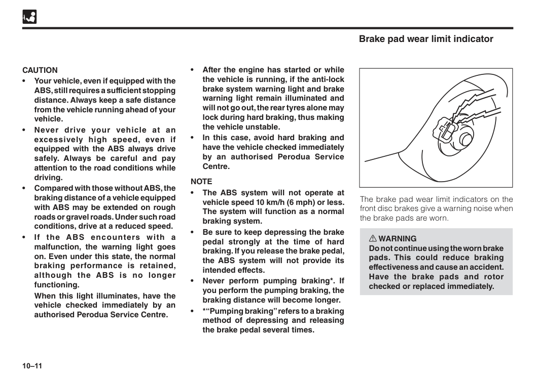
10–11 • After the engine has started or while the vehicle is running, if the anti-lock brake system warning light and brake warning light remain illuminated and will not go out, the rear tyres alone may lock during hard braking, thus making the vehicle unstable. • In this case, avoid hard braking and have the vehicle checked immediately by an authorised Perodua Service Centre.
Note
• The ABS system will not operate at vehicle speed 10 km/h (6 mph) or less. The system will function as a normal braking system. • Be sure to keep depressing the brake pedal strongly at the time of hard braking. If you release the brake pedal, the ABS system will not provide its intended effects. • Never perform pumping braking*. If you perform the pumping braking, the braking distance will become longer. • *“Pumping braking” refers to a braking method of depressing and releasing the brake pedal several times.Caution
• Your vehicle, even if equipped with the ABS, still requires a sufficient stopping distance. Always keep a safe distance from the vehicle running ahead of your vehicle. • Never drive your vehicle at an excessively high speed, even if equipped with the ABS always drive safely. Always be careful and pay attention to the road conditions while driving. • Compared with those without ABS, the braking distance of a vehicle equipped with ABS may be extended on rough roads or gravel roads. Under such road conditions, drive at a reduced speed. • If the ABS encounters with a malfunction, the warning light goes on. Even under this state, the normal braking performance is retained, although the ABS is no longer functioning.When this light illuminates, have the vehicle checked immediately by an authorised Perodua Service Centre. Brake pad wear limit indicator The brake pad wear limit indicators on the front disc brakes give a warning noise when the brake pads are worn. w WARNING Do not continue using the worn brake pads. This could reduce braking effectiveness and cause an accident. Have the brake pads and rotor checked or replaced immediately.
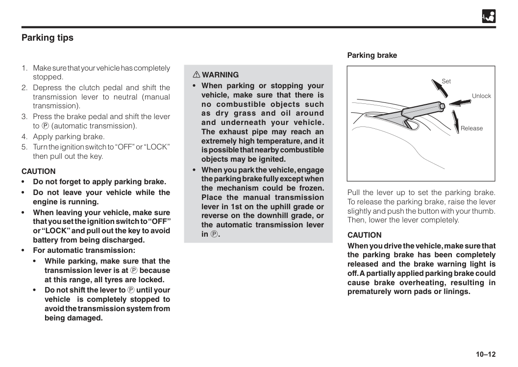
10–12 w WARNING
Caution
• Do not forget to apply parking brake. • Do not leave your vehicle while the engine is running. • When leaving your vehicle, make sure that you set the ignition switch to “OFF” or “LOCK” and pull out the key to avoid battery from being discharged. • For automatic transmission: • While parking, make sure that the transmission lever is at P because at this range, all tyres are locked. • Do not shift the lever to P until your vehicle is completely stopped to avoid the transmission system from being damaged. Parking brake Pull the lever up to set the parking brake. To release the parking brake, raise the lever slightly and push the button with your thumb. Then, lower the lever completely.Caution
When you drive the vehicle, make sure that the parking brake has been completely released and the brake warning light is off. A partially applied parking brake could cause brake overheating, resulting in prematurely worn pads or linings. Set Unlock Release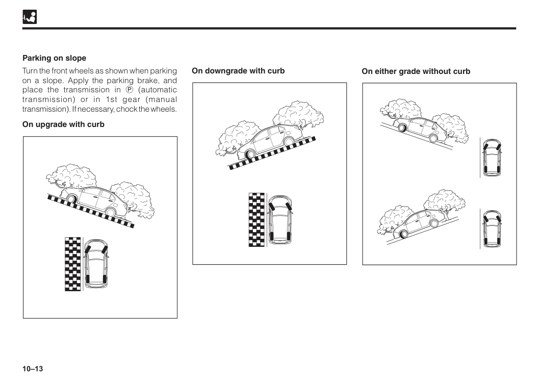
10–13 On downgrade with curb Parking on slope Turn the front wheels as shown when parking on a slope. Apply the parking brake, and place the transmission in P (automatic transmission) or in 1st gear (manual transmission). If necessary, chock the wheels. On upgrade with curb On either grade without curb
10–14 This vehicle is equipped with electric driven power steering (EPS). The power steering will not assist the steering efforts, unless the engine is running. Therefore, the steering operation requires increased force with the engine off.
Caution
If you notice any malfunction, have the system checked by an authorised Perodua Service Centre. Power steering The buzzer sounds when the vehicle speed exceeds 5km/h under condition of the parking brake is applied. Make sure to release the parking brake to avoid any damage to your vehicle. Parking brake warning buzzer Eco Idle is a system for automatically shutting down the engine when the vehicle is static and restarting it when the vehicle returns to motion. For the purpose of improving fuel consumption, reducing exhaust gas and minimizing idling noise, the system will automatically stop the engine (Eco Idle) and restart it when your vehicle is at a traffic light, in a traffic jam, etc. Eco Idle system (If equipped)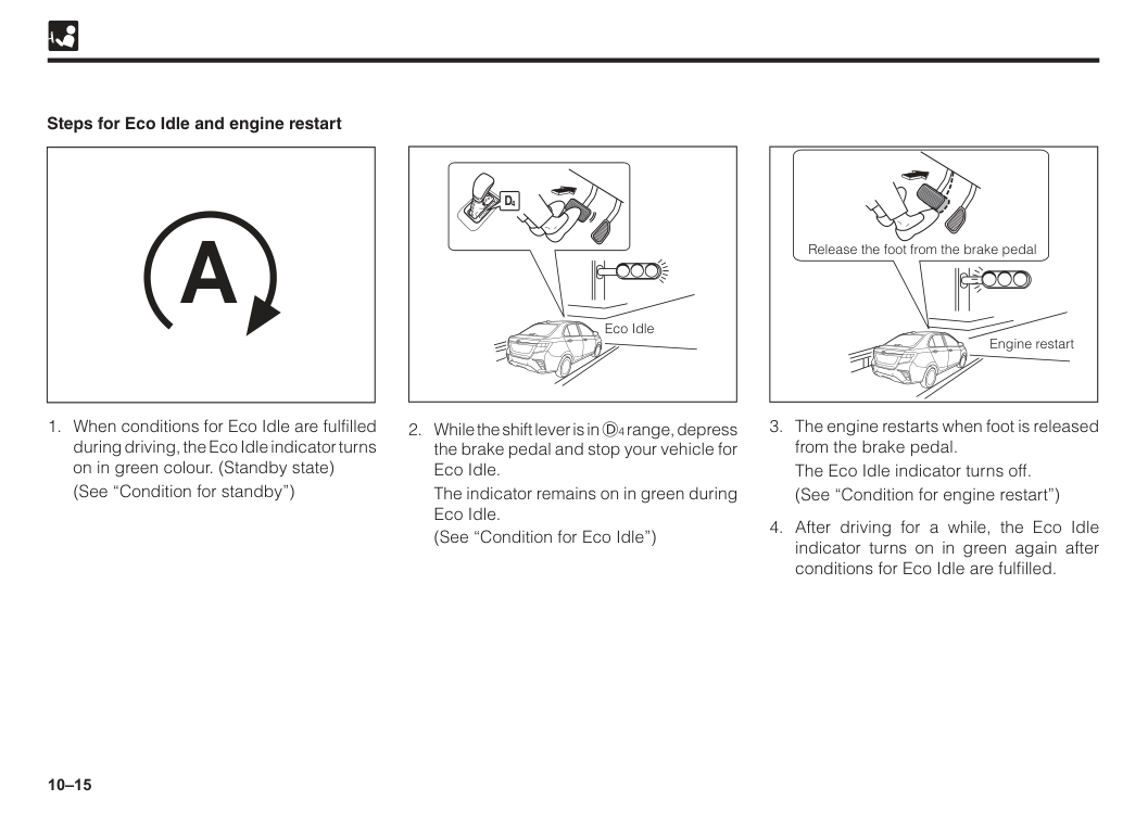
10–15 Steps for Eco Idle and engine restart
(See “Condition for standby”)
The indicator remains on in green during Eco Idle.
(See “Condition for Eco Idle”)
A
Eco IdleThe Eco Idle indicator turns off.
(See “Condition for engine restart”)
10–16 w WARNING
Caution
• During Eco Idle, the engine restarts if the accelerator pedal is depressed while depressing the brake pedal. Be careful when starting your vehicle. • Before leaving your vehicle or before parking your vehicle for a long time, make sure to apply the parking brake and operate the engine switch to stop the engine. For normal operation of Eco Idle • Eco Idle may not operate normally under the following conditions. Have the vehicle checked by an authorised Perodua Service Centre. • Seat belt warning light flashes, even though driver’s seat belt is fastened. • Seat belt warning light does not flash, even though driver’s seat belt is not fastened. • Door ajar warning light turns on or interior light turns on even though the driver’s door is closed or the interior light switch is in “DOOR” position. • Door ajar warning light does not turn on even though the driver’s door is opened or the interior light does not turn on when the interior light switch is in “DOOR” position. Precaution for Eco IdleNote
Operation during Eco Idle • Even if the shift level is moved from D4 range to the N range during Eco Idle, Eco Idle continues.Note that if shift level is moved to the N range before moving it further to other ranges, the engine restarts. • When you want to prepare for vehicle start during Eco Idle (e.g. right or left turn), you can restart the engine in advance by the following operations: • Quickly apply additional force to the brake pedal. • Press the Eco Idle OFF switch. Air conditioner operation during Eco Idle • During Eco Idle, cooling and dehumidifying functions of the air conditioner are stopped. Only ventilation function is available.
To return to normal operation, restart the engine by the following steps: • Quickly apply additional force to the brake pedal. • Operate the steering wheel. • Press the Eco Idle OFF switch.
10–17 Conditions for standby When all of the followings conditions are satisfied, the Eco Idle indicator turns on in green and Eco Idle becomes possible.
(While the operation of Eco Idle is stopped, Eco Idle OFF indicator turns on in orange)
Eat).
Note
In the following cases, it may take time before the standby state can be reached: • The battery has been discharged because the vehicle was not used for a long time. • The negative terminal of the battery has been removed for battery replacement. • At an initial stage of cooling. Conditions for Eco Idle When the standby conditions and the following conditions are satisfied, Eco Idle is activated with the Eco Idle indicator is turned on in green.Note
In the following cases, Eco Idle may not be activated: • The negative pressure of the brake booster has declined. • The force applied to the brake pedal is too weak. • Vehicle has stopped on a steep slope.
10–18 Conditions for engine restart The engine restarts when any of the following operations is performed during Eco Idle.
Note
Engine restart Under the following conditions, the engine restarts during Eco Idle and the creep phenomenon* occurs. Continue depressing the brake pedal fully. • Any of the conditions that prevent the Eco Idle from being operated (the Eco Idle indicator flashes in green and then turns off) : i. The negative pressure of the brake booster has declined. ii. The stopped vehicle starts moving on a slope. iii. The discharge capacity of the battery is too large. iv. An abnormality has occurred in the system(s), with the warning light on or flashing (ABS, VSC, EPS, EFI, EAT, etc). v. During cooling, air flow temperature at the air conditioner air outlet has risen. vi. Approximately 3 minutes has passed since Eco Idle. vii. An abnormality has occurred in the Eco Idle system or the engine part (starter) or battery requires replacement.(Eco Idle OFF indicator flashes in orange) *A phenomenon where the vehicle starts moving slowly without depressing the accelerator pedal, when power is conveyed because the shift lever is not in P or N range while the engine is running.
10–19 Cases where the Eco Idle time get shorter
To ensure safety, the engine will not restart even if you have released your foot from the brake pedal.
The warning buzzer will sound and Eco Idle indicator flashes. Operation of electrical parts during engine restart
i. Audio sytem
ii. GPS or navigation system
Caution
• If a battery other than the dedicated one is used, the battery may get degraded faster and Eco Idle system may not operate normally. • Do not take power supply to the electric component assembly directly from the battery terminal. Eco Idle system will stop operating normally.Note
• Periodic charging of the battery enables a longer lifetime. For details, consult with an authorised Perodua Service Centre. Eco Idle system designated battery
10–20 • If you press the VSC OFF switch more than 3 seconds, VSC (including TRC) will not operate and the VSC OFF and TRC OFF indicator lights will illuminate. • The condition of the tyres has a large influence on the system. Make sure that all tyres are in good condition. w WARNING
Caution
All four tyres should be of the same size, manufacturer, brand, and tread pattern, as well as free of wear. Installing tyres not designated for your vehicle may cause VSC to function incorrectly.Note
• VSC can be operated when the vehicle speed exceeds about 15 km/h. • Even if you have deactivated the system, VSC (including TRC), will return to the operability state every time you start the engine. • When starting the engine or immediately after the vehicle has started, you may hear a clicking or thumping sound. This is the sound of system operation check and not a malfunction. (See “VSC OFF switch” in Section 4) (See “Slip indicator light, VSC OFF indicator and TRC OFF indicator” in Section 5) VSC is a system that automatically maintains the stability of the vehicle by controlling the brakes in order to restrict swerving or skidding during sudden steering wheel movements or on a slippery road.Trc
TRC functions TRC is a system that ensures the stability and driving force of the vehicle by controlling the wheel spin of the driving wheel when excessive throttle is applied during taking off or accelerating on slippery road. If the wheels start to slip, the computer will detect it based on information from the wheel speed sensors, and apply braking as necessary. From this, it controls the excessive driving force and prevents slipping. • If you press the VSC OFF switch, TRC will not operate and TRC OFF indicator lights will illuminate. • TRC will not operate when the TRC OFF indicator light is illuminated. • If the TRC activates, you may notice the vehicle vibrate which is caused by brake control and not a malfunction. • When stuck in mud, you may not be able to free your vehicle if TRC is in operation. In this case, the VSC OFF switch can be used to disable TRC. VSC (Vehicle stability control) • TRC (Traction control) (If equipped)Vsc
10–21 TRC mechanism The computer compares the tyre slip signals from sensors connected to all 4 wheels. If the signal from one of the driving wheels is more than the other wheels, the computer will interpret that the vehicle is slipping. A brake may be applied to reduce the driving force to the slipping tyre in order to control the slip. TRC and tyre connection
Caution
All four tyres should be of the same size, manufacturer, brand, and tread pattern, as well as free of wear. Installing tyres not designated for your vehicle may cause TRC to function incorrectly.Note
• Usually, when you turn the ignition switch to “ON”, TRC will be in a ready state. • When starting the engine or immediately after the vehicle has started, you may hear a clicking or thumping sound. This is the sound of system operation check and not a malfunction. (See “VSC OFF switch” in Section 4) (See “Slip indicator light”, VSC OFF indicator and TRC OFF indicator” in Section 5)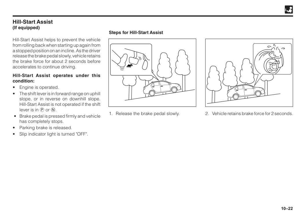
10–22 Hill-Start Assist helps to prevent the vehicle from rolling back when starting up again from a stopped position on an incline. As the driver release the brake pedal slowly, vehicle retains the brake force for about 2 seconds before accelerates to continue driving. Hill-Start Assist operates under this condition:
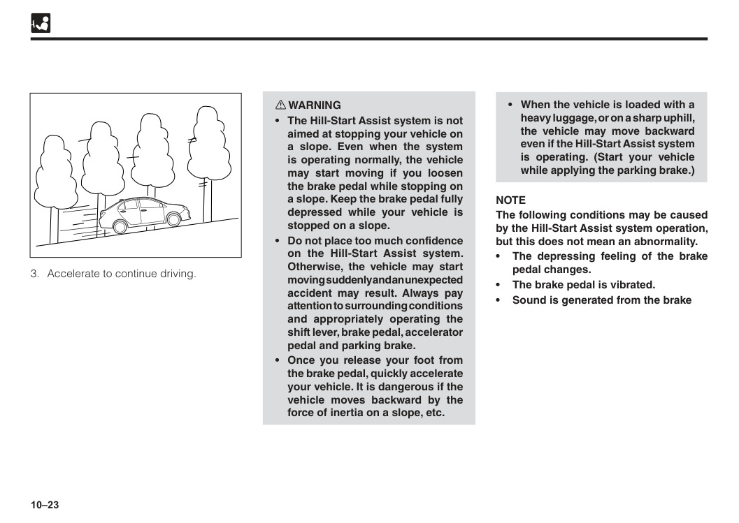
10–23
Note
The following conditions may be caused by the Hill-Start Assist system operation, but this does not mean an abnormality. • The depressing feeling of the brake pedal changes. • The brake pedal is vibrated. • Sound is generated from the brake
10–24 ESS (Emergency Stop Signal) is a system to reduce the possibility of rear-end collision by lashes the hazard warning signal light when sudden brake is applied, to warn the vehicles that follow. ESS operates under this condition:
10–25 w WARNING Obligation of safe driving
10–26
Note
• When the ignition switch is turned “ON” ASA will be in a ready state. • Even if you have deactivated (turn off) the system, ASA will return to the operation state every time you start the engine.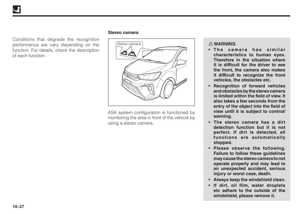
10–27 Conditions that degrade the recognition performance are vary depending on the function. For details, check the description of each function. w WARNING
10–28
part of the instrument panel with a chemical agent or the like, reflection to the windshield may cause the recognition of stereo camera unstable and the system may not operate properly.
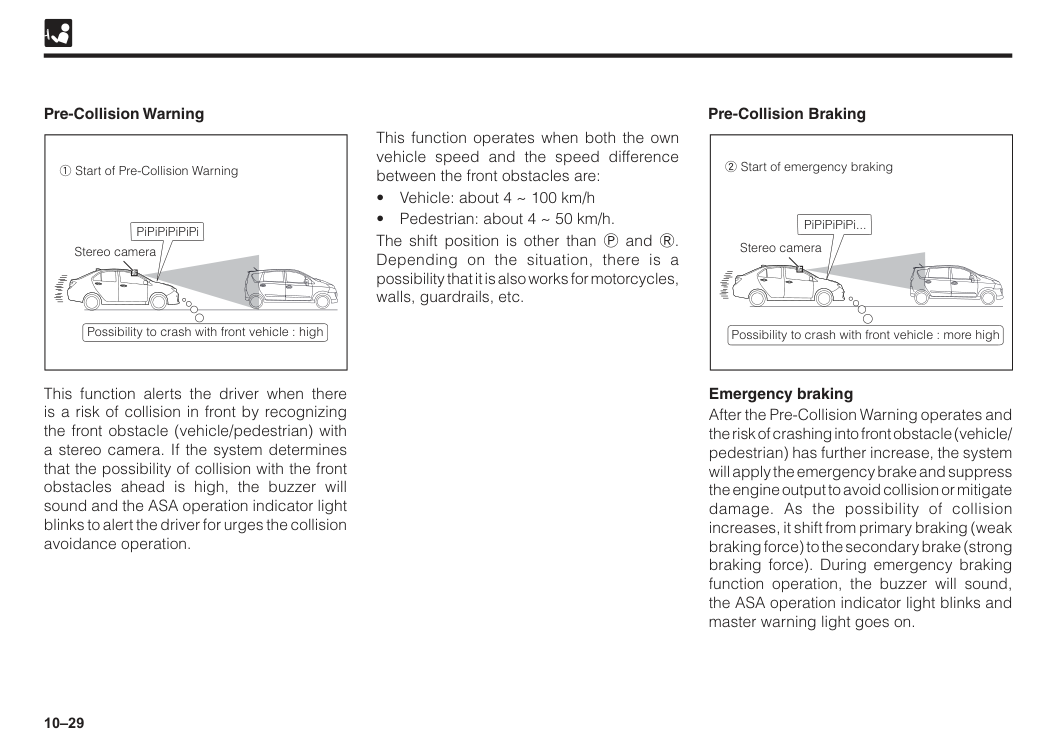
10–29 Pre-Collision Warning Pre-Collision Braking This function alerts the driver when there is a risk of collision in front by recognizing the front obstacle (vehicle/pedestrian) with a stereo camera. If the system determines that the possibility of collision with the front obstacles ahead is high, the buzzer will sound and the ASA operation indicator light blinks to alert the driver for urges the collision avoidance operation. This function operates when both the own vehicle speed and the speed difference between the front obstacles are:
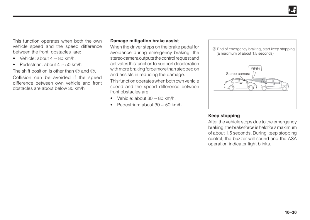
10–30 Keep stopping After the vehicle stops due to the emergency braking, the brake force is held for a maximum of about 1.5 seconds. During keep stopping control, the buzzer will sound and the ASA operation indicator light blinks. Damage mitigation brake assist When the driver steps on the brake pedal for avoidance during emergency braking, the stereo camera outputs the control request and activates this function to support deceleration with more braking force more than stepped on and assists in reducing the damage. This function operates when both own vehicle speed and the speed difference between front obstacles are:
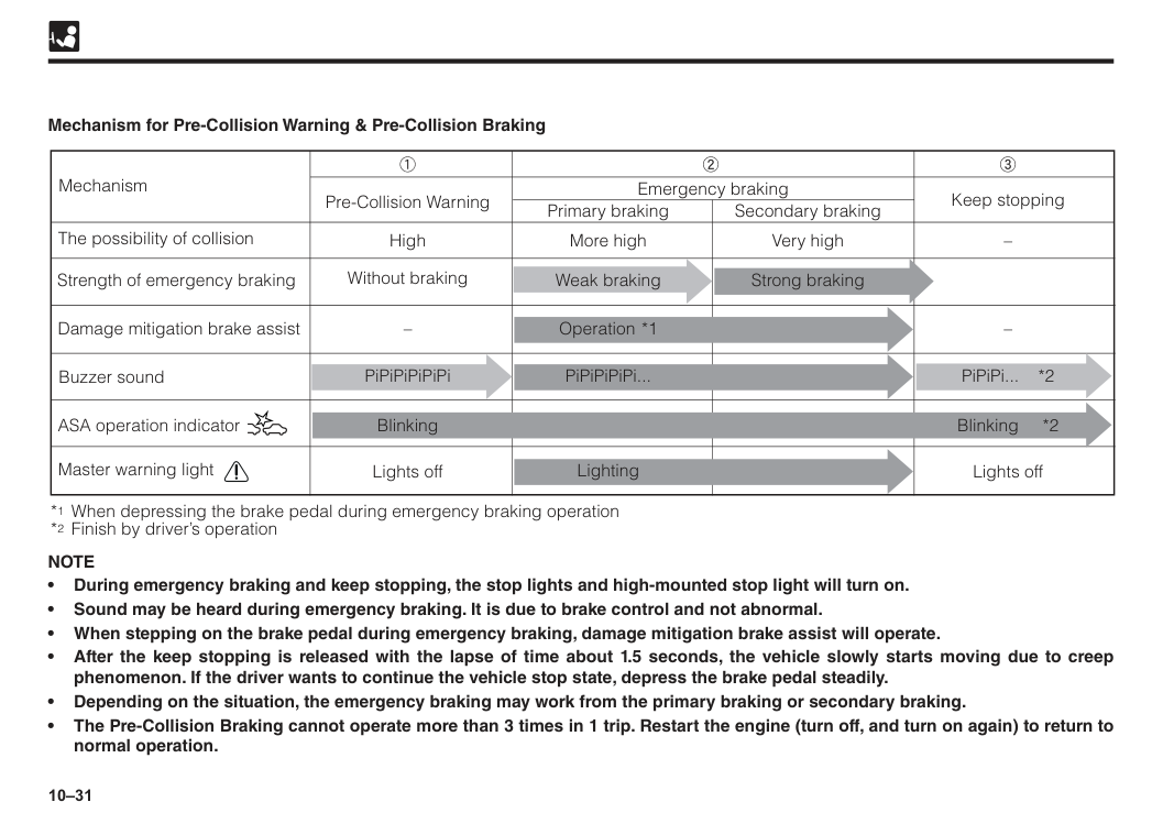
10–31 The possibility of collision Mechanism Strength of emergency braking Damage mitigation brake assist Buzzer sound Master warning light *1 When depressing the brake pedal during emergency braking operation *2 Finish by driver’s operation Pre-Collision Warning Primary braking Emergency braking Secondary braking Keep stopping High Lights off Lights off Without braking More high Very high – – 1 2 3 Weak braking PiPiPiPiPiPi Blinking Blinking *2 Lighting PiPiPiPiPi... Operation *1 PiPiPi... *2 Strong braking ASA operation indicator – Mechanism for Pre-Collision Warning & Pre-Collision Braking
Note
• During emergency braking and keep stopping, the stop lights and high-mounted stop light will turn on. • Sound may be heard during emergency braking. It is due to brake control and not abnormal. • When stepping on the brake pedal during emergency braking, damage mitigation brake assist will operate. • After the keep stopping is released with the lapse of time about 1.5 seconds, the vehicle slowly starts moving due to creep phenomenon. If the driver wants to continue the vehicle stop state, depress the brake pedal steadily. • Depending on the situation, the emergency braking may work from the primary braking or secondary braking. • The Pre-Collision Braking cannot operate more than 3 times in 1 trip. Restart the engine (turn off, and turn on again) to return to normal operation.
10–32 w WARNING
10–33 Inactivity situation The stereo camera recognize pedestrian for Pre-Collision Warning and Pre-Collision Braking function. The pedestrian recognition is done from the size, shape and movement of the object. It recognizes when the contours of the head and shoulders are clear. Following cases may result into Pre-Collision Warning and Pre-Collision Braking may not operate and may not stop completely.
10–34
10–35 Unnecessary operation In the following cases, Pre-Collision Warning and Pre-Collision Braking may operate unexpectedly. Therefore, be sure to turn off the ASA function. (See “ASA OFF switch” in section 4)
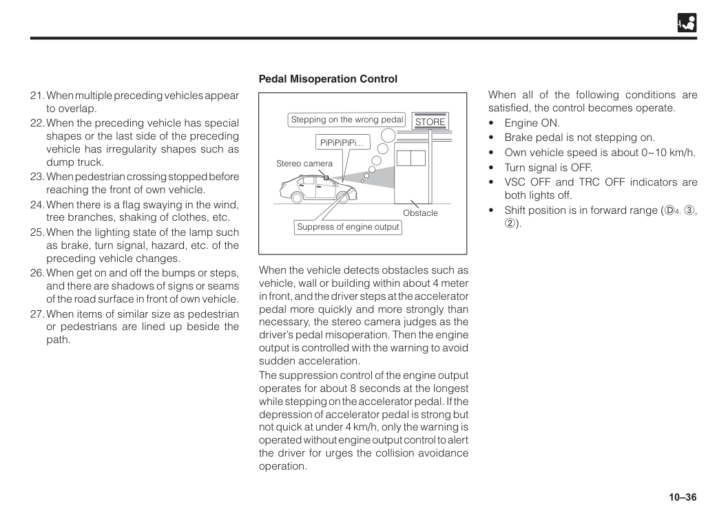
10–36 When the vehicle detects obstacles such as vehicle, wall or building within about 4 meter in front, and the driver steps at the accelerator pedal more quickly and more strongly than necessary, the stereo camera judges as the driver’s pedal misoperation. Then the engine output is controlled with the warning to avoid sudden acceleration. The suppression control of the engine output operates for about 8 seconds at the longest while stepping on the accelerator pedal. If the depression of accelerator pedal is strong but not quick at under 4 km/h, only the warning is operated without engine output control to alert the driver for urges the collision avoidance operation. When all of the following conditions are satisfied, the control becomes operate.
Store
Obstacle Stereo camera Suppress of engine output
10–37 w WARNING
10–38
When the own vehicle is in a sharp curve, or a sudden uphill/downhill.
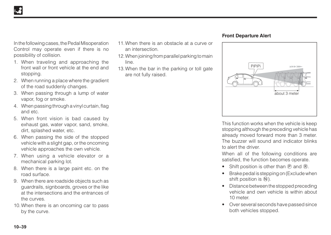
10–39 In the following cases, the Pedal Misoperation Control may operate even if there is no possibility of collision.
10–40
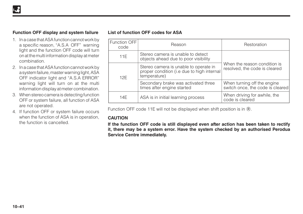
10–41 Function OFF display and system failure List of function OFF codes for ASA
11E
12E
14E
Stereo camera is unable to detect objects ahead due to poor visibility When the reason condition is resolved, the code is cleared When turning off the engine switch once, the code is cleared When driving for awhile, the code is cleared Stereo camera is unable to operate in proper condition (i.e due to high internal temperature) Secondary brake was activated three times after engine started ASA is in initial learning process Function OFF code Reason Restoration Function OFF code 11E will not be displayed when shift position is in R.Caution
If the function OFF code is still displayed even after action has been taken to rectify it, there may be a system error. Have the system checked by an authorised Perodua Service Centre immediately.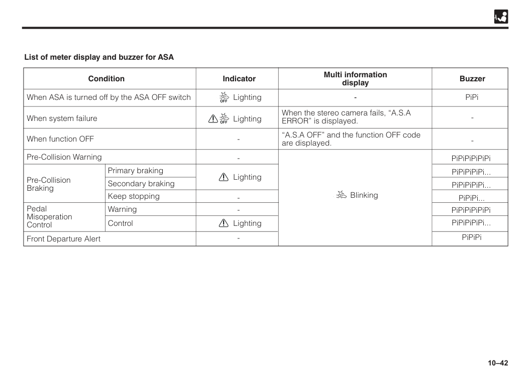
10–42 When ASA is turned off by the ASA OFF switch Front Departure Alert When system failure When function OFF Pre-Collision Warning Primary braking Secondary braking Keep stopping Warning Control Pre-Collision Braking Pedal Misoperation Control When the stereo camera fails, “A.S.A ERROR” is displayed. “A.S.A OFF” and the function OFF code are displayed.
Off
Lighting LightingOff
Lighting Blinking List of meter display and buzzer for ASA
10–43 Vehicle data recording Data usage Advanced Safety Assist (ASA) is equipped with a computer which record data concerning the vehicle control and operations. The record data are mainly as follows. • Operation status of accelerator pedal. • Operation status of brake pedal. • Operation status of steering wheel and shift lever. • Vehicle information such as vehicle speed. • Operation status of each ASA function. • Distance between to an obstacle such as preceding vehicle, relative speed, etc. • Image data of the stereo camera (only when operating the secondary brake). Furthermore, the computer does not record conversations, sounds or pictures in the vehicle. Perodua may use the data recorded in these computers to diagnose malfunctions, conduct research and development, and improve quality. Perodua will not disclose the recorded data to a third party except : • With the consent of the vehicle owner or with the consent of the lessee if the vehicle is leased. • In response to an official request by police, a court of law or a government agency. • For use by Perodua in a lawsuit. • For research purposes where the data is not tied to a specific vehicle or vehicle owner. The recorded image data can be erased using a special device. It is possible to stop the function of recording the image data. For details, contact an authorised Perodua service centre.
11 If engine won’t start..........................................................................11–1 Jump-starting....................................................................................11–2 Engine overheating..........................................................................11–4 Tools..................................................................................................11–5 Flat tyre..............................................................................................11–7 Towing...............................................................................................11–14 Warning sounds................................................................................11–17 Section 11 In case of an emergency
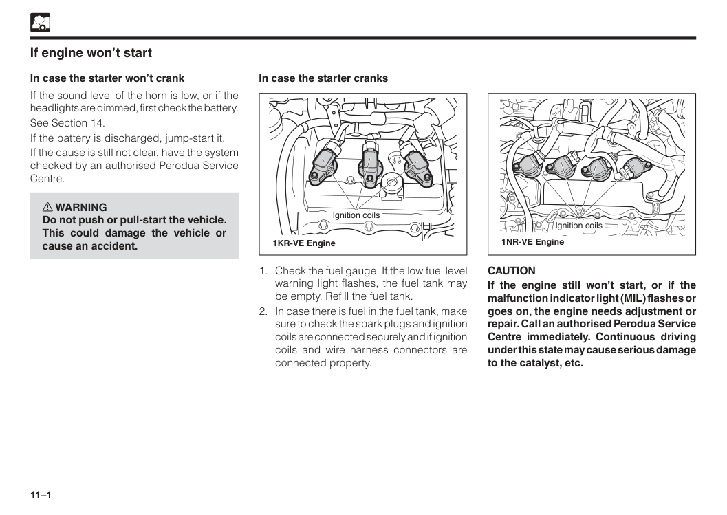
11–1 If engine won’t start In case the starter won’t crank If the sound level of the horn is low, or if the headlights are dimmed, first check the battery. See Section 14. If the battery is discharged, jump-start it. If the cause is still not clear, have the system checked by an authorised Perodua Service Centre. w WARNING Do not push or pull-start the vehicle. This could damage the vehicle or cause an accident. In case the starter cranks
Caution
If the engine still won’t start, or if the malfunction indicator light (MIL) flashes or goes on, the engine needs adjustment or repair. Call an authorised Perodua Service Centre immediately. Continuous driving under this state may cause serious damage to the catalyst, etc.
11–2 Jump-starting w WARNING Observe the following instructions to prevent serious bodily injury and damage to your vehicle.
Caution
• Use a 12-volt booster battery. Application of higher voltage may cause serious damage to the electrical equipment such as relays and radio. Do not jump-start the vehicle unless you are sure of the booster battery voltage. • The capacity (AH rating) of the booster battery must not be lower than that of the discharged battery. • Wash splashed battery fluid away from paint finish immediately.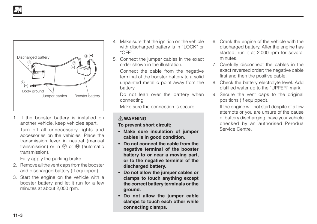
11–3
Turn off all unnecessary lights and accessories on the vehicles. Place the transmission lever in neutral (manual transmission) or in P or N (automatic transmission).
Fully apply the parking brake.
If the engine will not start despite of a few attempts or you are unsure of the cause of battery discharging, have your vehicle checked by an authorised Perodua Service Centre.
“Off”.
Connect the cable from the negative terminal of the booster battery to a solid unpainted metallic point away from the battery.
Do not lean over the battery when connecting.
Make sure the connection is secure. w WARNING To prevent short circuit;
11–4 Engine overheating If the engine overheats, the engine emits pinging noises and engine performance drops noticeably as well as the engine coolant temperature gauge indicates overheating. In this case, observe the following WARNINGS and follow the procedure described. w WARNING To help reduce the risk of burn or serious bodily injury;
The engine is more prone to overheat in hot weather. The following should be checked regularly:
If the engine overheats frequently, have the cooling system checked by an authorised Perodua Service Centre.
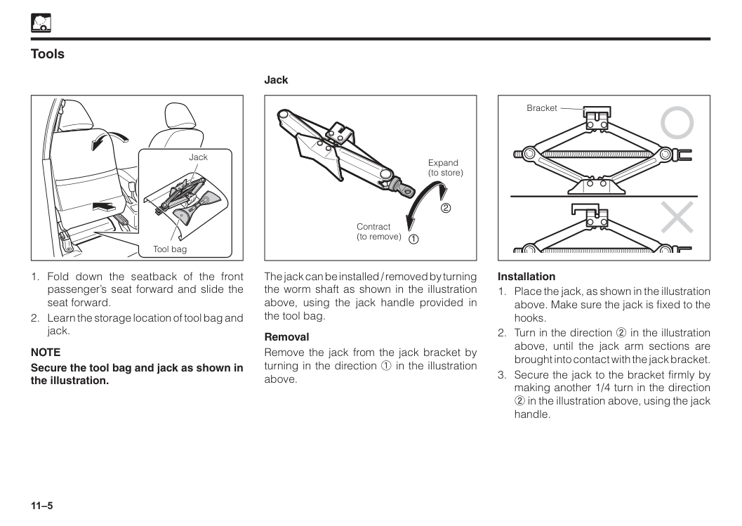
11–5 Tools Jack Tool bag
Note
Secure the tool bag and jack as shown in the illustration. Expand (to store) Contract (to remove) 2 1 The jack can be installed / removed by turning the worm shaft as shown in the illustration above, using the jack handle provided in the tool bag. Removal Remove the jack from the jack bracket by turning in the direction 1 in the illustration above. Jack Bracket Installation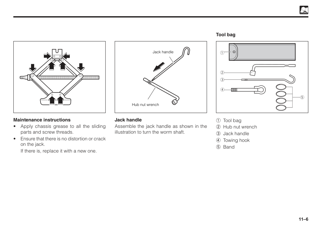
11–6 Maintenance instructions
If there is, replace it with a new one. Tool bag Jack handle Assemble the jack handle as shown in the illustration to turn the worm shaft. Jack handle Hub nut wrench 1 Tool bag 2 Hub nut wrench 3 Jack handle 4 Towing hook 5 Band
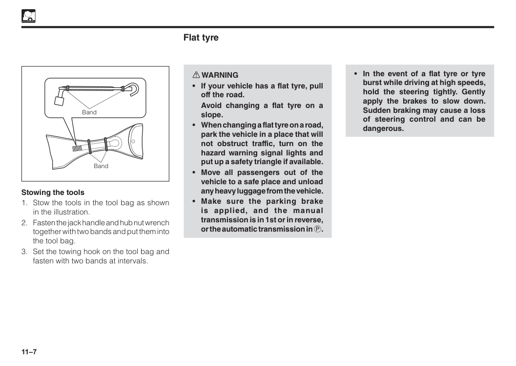
11–7 Stowing the tools
Avoid changing a flat tyre on a slope.
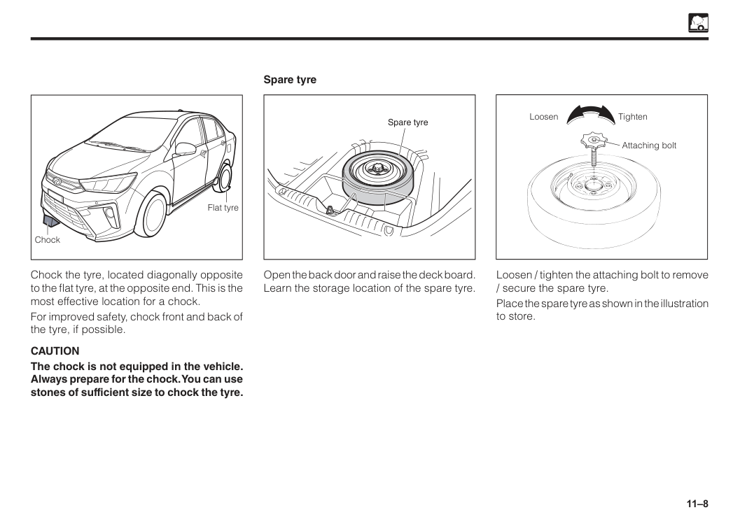
11–8 Spare tyre Spare tyre Open the back door and raise the deck board. Learn the storage location of the spare tyre. Chock the tyre, located diagonally opposite to the flat tyre, at the opposite end. This is the most effective location for a chock. For improved safety, chock front and back of the tyre, if possible.
Caution
The chock is not equipped in the vehicle. Always prepare for the chock. You can use stones of sufficient size to chock the tyre. Flat tyre Chock Tighten Loosen Attaching bolt Loosen / tighten the attaching bolt to remove / secure the spare tyre. Place the spare tyre as shown in the illustration to store.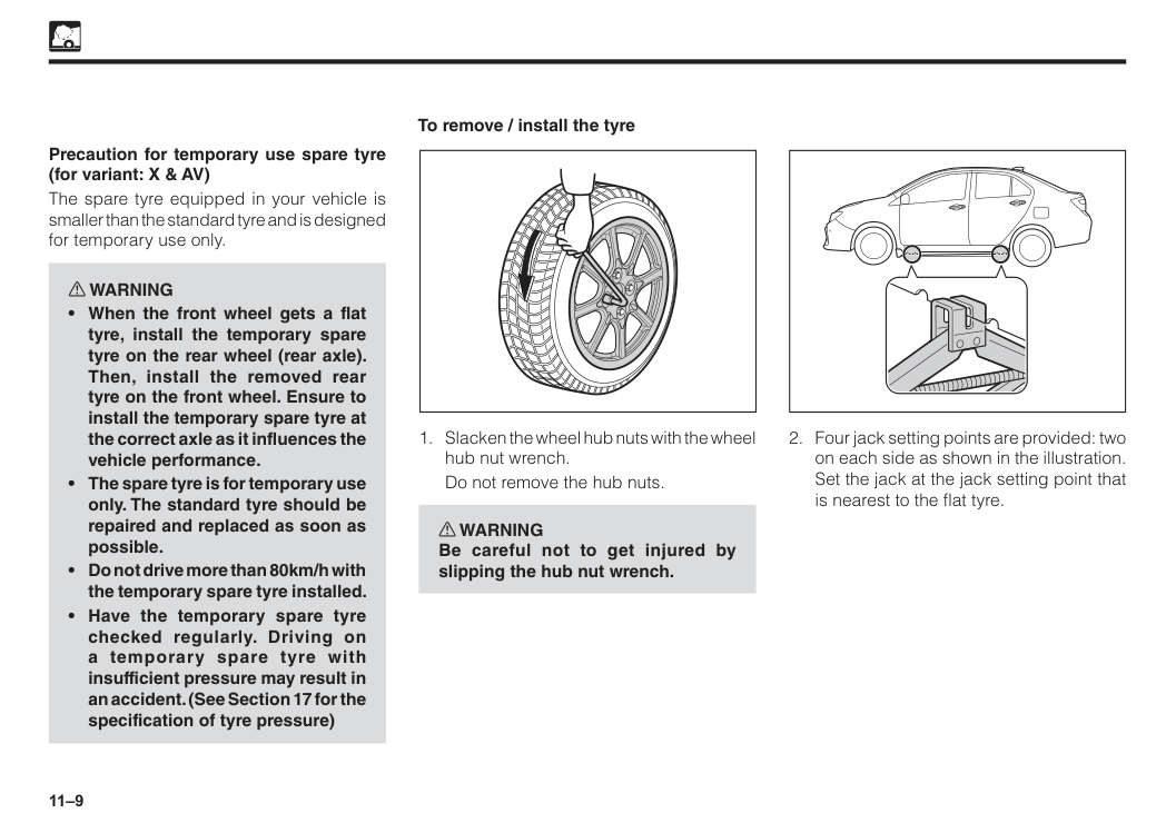
11–9 To remove / install the tyre
Do not remove the hub nuts. w WARNING Be careful not to get injured by slipping the hub nut wrench. Precaution for temporary use spare tyre (for variant: X & AV) The spare tyre equipped in your vehicle is smaller than the standard tyre and is designed for temporary use only. w WARNING
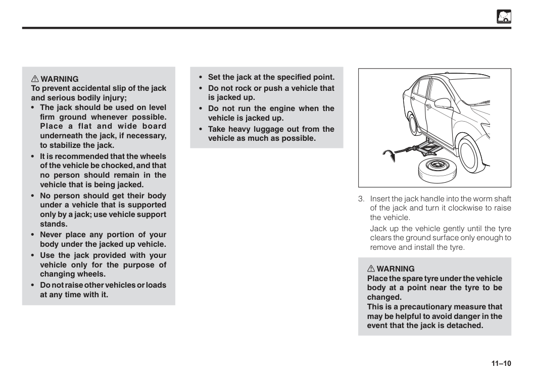
11–10 w WARNING To prevent accidental slip of the jack and serious bodily injury;
Jack up the vehicle gently until the tyre clears the ground surface only enough to remove and install the tyre. w WARNING Place the spare tyre under the vehicle body at a point near the tyre to be changed. This is a precautionary measure that may be helpful to avoid danger in the event that the jack is detached.
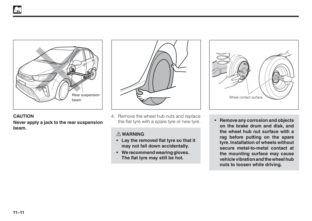
11–11
Caution
Never apply a jack to the rear suspension beam. Rear suspension beam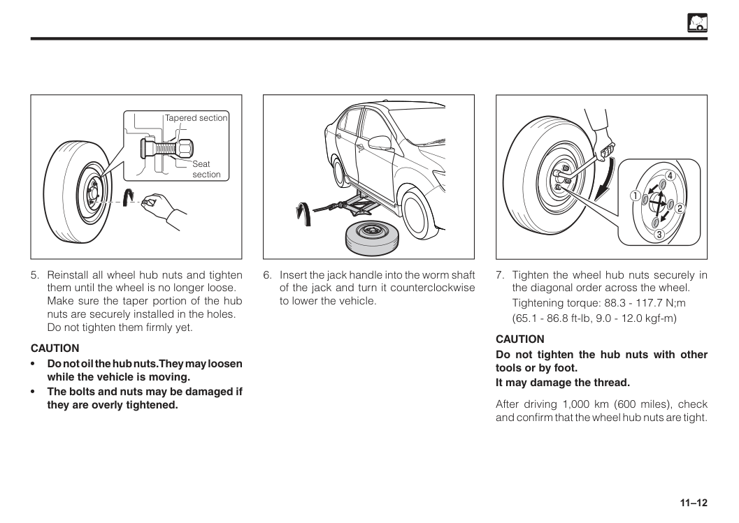
11–12 Seat section Tapered section
Caution
• Do not oil the hub nuts. They may loosen while the vehicle is moving. • The bolts and nuts may be damaged if they are overly tightened.Tightening torque: 88.3 - 117.7 N;m
(65.1 - 86.8 ft-lb, 9.0 - 12.0 kgf-m)
Caution
Do not tighten the hub nuts with other tools or by foot. It may damage the thread. After driving 1,000 km (600 miles), check and confirm that the wheel hub nuts are tight.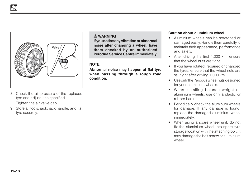
11–13
Tighten the air valve cap.
Note
Abnormal noise may happen at flat tyre when passing through a rough road condition. Caution about aluminium wheel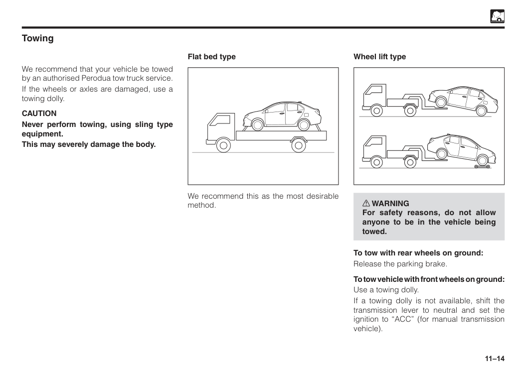
11–14 Towing We recommend that your vehicle be towed by an authorised Perodua tow truck service. If the wheels or axles are damaged, use a towing dolly.
Caution
Never perform towing, using sling type equipment. This may severely damage the body. Flat bed type We recommend this as the most desirable method. w WARNING For safety reasons, do not allow anyone to be in the vehicle being towed. To tow with rear wheels on ground: Release the parking brake. To tow vehicle with front wheels on ground: Use a towing dolly. If a towing dolly is not available, shift the transmission lever to neutral and set the ignition to “ACC” (for manual transmission vehicle). Wheel lift type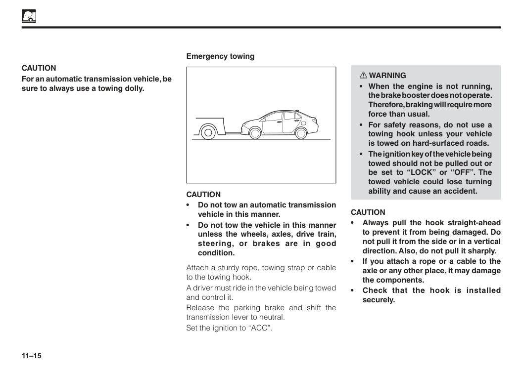
11–15
Caution
For an automatic transmission vehicle, be sure to always use a towing dolly. Emergency towingCaution
• Do not tow an automatic transmission vehicle in this manner. • Do not tow the vehicle in this manner unless the wheels, axles, drive train, steering, or brakes are in good condition. Attach a sturdy rope, towing strap or cable to the towing hook. A driver must ride in the vehicle being towed and control it. Release the parking brake and shift the transmission lever to neutral. Set the ignition to “ACC”. w WARNINGCaution
• Always pull the hook straight-ahead to prevent it from being damaged. Do not pull it from the side or in a vertical direction. Also, do not pull it sharply. • If you attach a rope or a cable to the axle or any other place, it may damage the components. • Check that the hook is installed securely.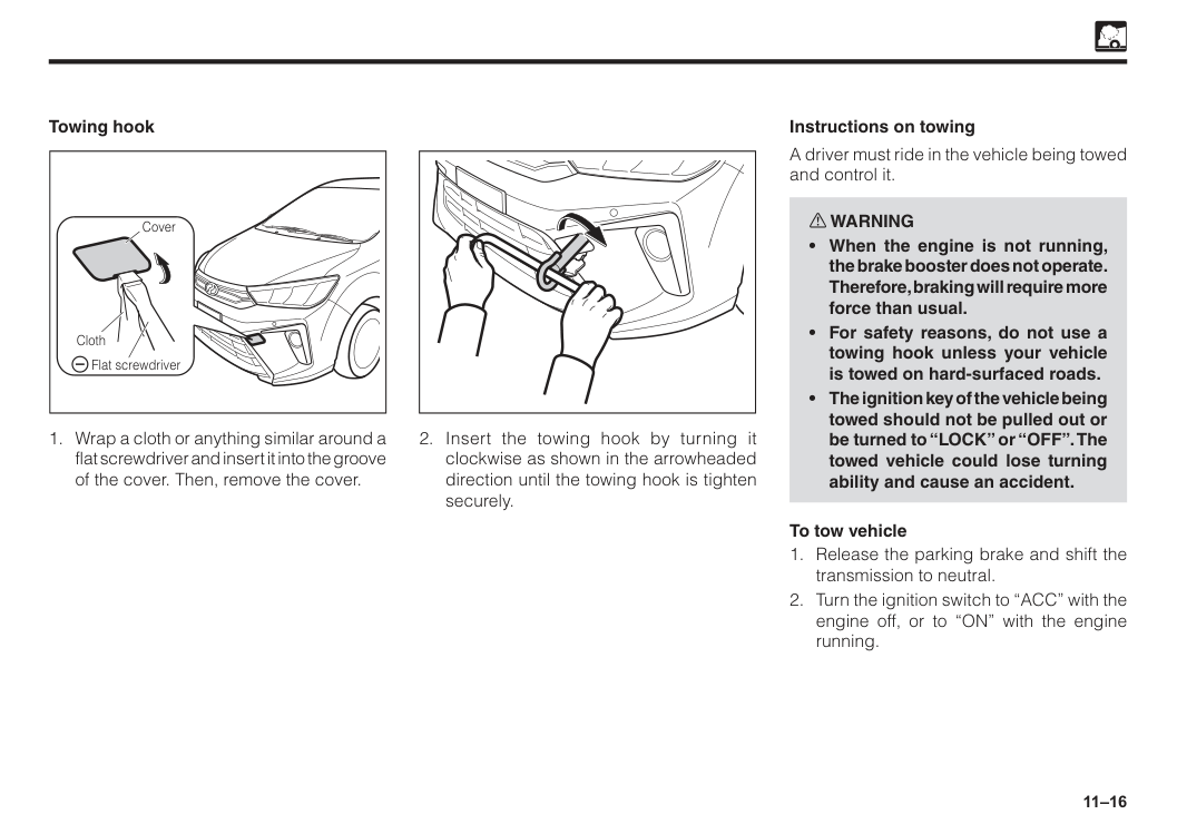
11–16 Cover Cloth Flat screwdriver Towing hook
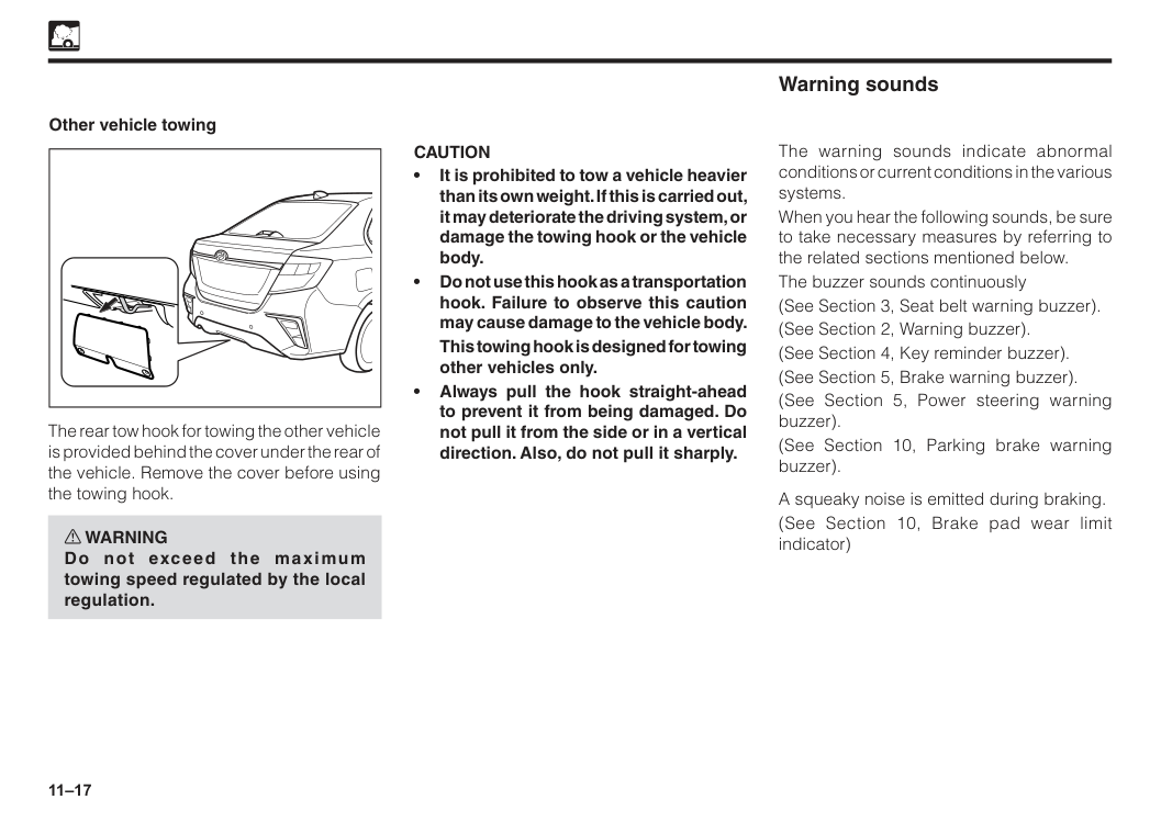
11–17 Other vehicle towing The rear tow hook for towing the other vehicle is provided behind the cover under the rear of the vehicle. Remove the cover before using the towing hook. w WARNING Do not exceed the maximum towing speed regulated by the local regulation.
Caution
• It is prohibited to tow a vehicle heavier than its own weight. If this is carried out, it may deteriorate the driving system, or damage the towing hook or the vehicle body. • Do not use this hook as a transportation hook. Failure to observe this caution may cause damage to the vehicle body.This towing hook is designed for towing other vehicles only. • Always pull the hook straight-ahead to prevent it from being damaged. Do not pull it from the side or in a vertical direction. Also, do not pull it sharply. The warning sounds indicate abnormal conditions or current conditions in the various systems. When you hear the following sounds, be sure to take necessary measures by referring to the related sections mentioned below. The buzzer sounds continuously (See Section 3, Seat belt warning buzzer). (See Section 2, Warning buzzer). (See Section 4, Key reminder buzzer). (See Section 5, Brake warning buzzer). (See Section 5, Power steering warning buzzer). (See Section 10, Parking brake warning buzzer). A squeaky noise is emitted during braking. (See Section 10, Brake pad wear limit indicator) Warning sounds

12 Exterior cleaning..............................................................................12–1 Interior cleaning................................................................................12–2 Rust prevention................................................................................12–3 Section 12 Appearance care
12–1 Exterior cleaning Washing
Turn the engine off.
Caution
• Be careful not to apply water to the electrical systems in the engine compartment. This could cause short circuit. • Follow the instructions on washing solution.Gasoline or strong toxic solvents are not recommended to protect paint finish. • Do not apply hot water on the vehicle. This could damage the paint finish. Also, do not wipe off dirt or dust if the body surface is dry. When using an automatic car wash machine
Caution
• Set the air intake control lever or switch on the air conditioner control panel to “recirculation”. Otherwise, water will enter inside the vehicle and may cause a malfunction. • Close the side mirror. Wash the vehicle from the front. Make sure to extend the mirrors before driving. • Brush may occasionally scratch the vehicle and cause loss of paint gloss or early deterioration. When using a high-pressure car wash machineCaution
• Water may go inside the vehicle if the nozzle is pointed at an open/close part such as a door window and around the door. Do not bring the nozzle too close to these areas.
12–2 Wax your vehicle on a regular basis to preserve the paint finish. Wash and dry the vehicle before waxing. If the paint finish is hot, move the vehicle into shade and allow the surface to cool before waxing.
Caution
To protect paint finish; • Do not rub the surface hard or rub with hard cloth. • Do not use steel wool or abrasive cleanser. • Follow the instructions of the wax manufacturer. Waxing Interior cleaning Clean the interior with a vacuum cleaner. To clean leather, plastic, and cloth materials, (such as air conditioning control panel, audio panel, instrument panel, console panel, switches, etc) use a soft cloth dampened with a solution of mild soap and lukewarm water. After cleaning, completely remove the remaining soap with a soft cloth dampened with water.Caution
Gasoline or strong toxic solvents are not recommended. It may damage the materials.Caution
• Do not use organic substances (solvents, kerosene, alchohol, gasoline, etc.) or alkaline or acidic solutions. These chemicals can cause discoloring, staining or peeling of the surface. • If you use cleaners or polishing agents, make sure their ingredients, do not include the substances mentioned above. • If you use a liquid car freshener, do not spill the liquid onto the vehicle’s interior surfaces. It may contain the ingredients mentioned above. Immediately clean any spill using the method mentioned above. • When letting the cleaned part dry, avoid direct rays of sun. Let it dry at a well ventilated, shaded, dust-free place. Otherwise, the materials may deteriorate quickly.
12–3 Rust preventive measures Keep your Perodua clean; If you live in an area where rust formation is prone to occur, such as where salt is sprinkled on roads, near seacoast, or where industrial pollutants spread, be especially careful of rust formation. We recommend washing the underside of your vehicle at least once a month. Clean the fenders and other parts hidden from you. Wash away mud thoroughly as wet mud could promote rust formation. When cleaning the under-side of the doors, rocker panels, frame members, and so forth, make sure the water drain holes are not clogged. Keep your garage dry; Moisture is harmful for your vehicle, especially over 0oC. Therefore, do not park your vehicle in a poorly-ventilated area with high humidity. Do not wash your vehicle in a garage or keep your vehicle in a wet condition. Keep paint finish and trim in good conditions; Any scratch or chip on the paint finish must be touched up as soon as possible. Have the bare steel repaired at a qualified body repair shop or an authorised Perodua Service Centre. Pay attention to interior; Check, at regular intervals, that under-side of the mats and carpets are dry. Do not wash the interior. Furthermore, carry chemicals, cleansers, fertilizers, salt, etc., in a proper container. If it has spilt or leaked, clean and dry the area immediately. Rust prevention We at Perodua have been producing high-quality vehicles with advanced rust preventive design and construction. Nevertheless, this constitutes merely part of a total rust prevention program. To maintain good rust preventive quality for a long period of time, it is important for you to understand what to do on your part. w WARNING Do not coat the exhaust system components with additional rust preventive materials. This could overheat and cause a fire. Cause of rust formation The followings are usual causes of rust:

13 Maintenance requirements..............................................................13–1 Maintenance schedule.....................................................................13–3 Section 13 Vehicle maintenance service
13–1 Maintenance requirements (General precaution)
13–2 Carefully monitor your Perodua Monitor your Perodua for changes in performance, sounds, and visual tip-offs that indicate requirement of maintenance service. Some important clues are as follows:
(Water drainage from the air conditioner is normal.)
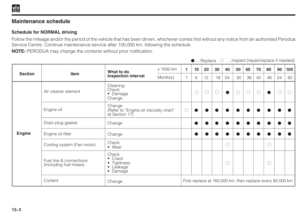
13–3 Follow the mileage and/or the period of the vehicle that has been driven, whichever comes first without any notice from an authorised Perodua Service Centre. Continue maintenance service after 100,000 km, following the schedule. NOTE: PERODUA may change the contents without prior notification. Section Engine Item What to do Inspection interval x 1000 km Month(s) 30 50 24 40 18 30 12 20 6 10 36 60 42 70 48 80 54 90 60 100 Air cleaner element Cleaning Check
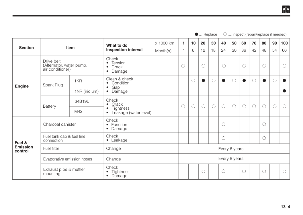
13–4 Section Engine Item What to do Inspection interval x 1000 km Month(s) 30 50 24 40 18 30 12 20 6 10 36 60 42 70 48 80 54 90 60 100 Drive belt (Alternator, water pump, air conditioner) Check
1Kr
1NR (iridium) Clean & check34B19L
M42
1 1 Fuel & Emission control Charcoal canister Check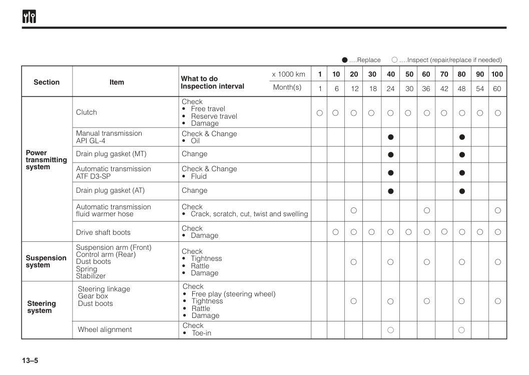
13–5 Section Power transmitting system Suspension system Item What to do Inspection interval Check
Api Gl-4
Automatic transmissionAtf D3-Sp
Automatic transmission fluid warmer hose Drive shaft boots Check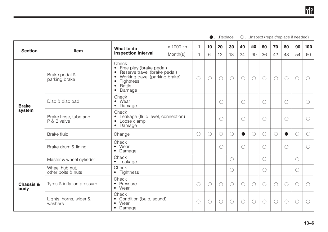
13–6 Section Brake system Item What to do Inspection interval Check
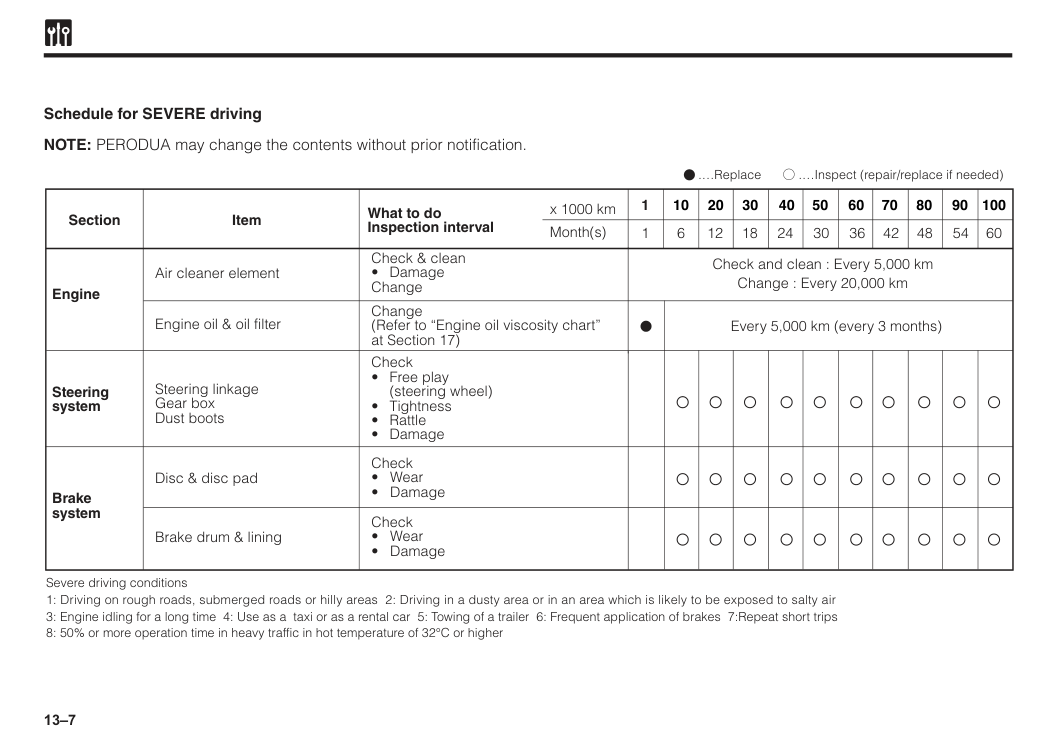
13–7 Schedule for SEVERE driving NOTE: PERODUA may change the contents without prior notification. Section Engine Item What to do Inspection interval x 1000 km Month(s) 50 40 30 20 10 1 60 70 80 90 100 Air cleaner element Check and clean : Every 5,000 km Change : Every 20,000 km Every 5,000 km (every 3 months) Check & clean
(steering wheel)
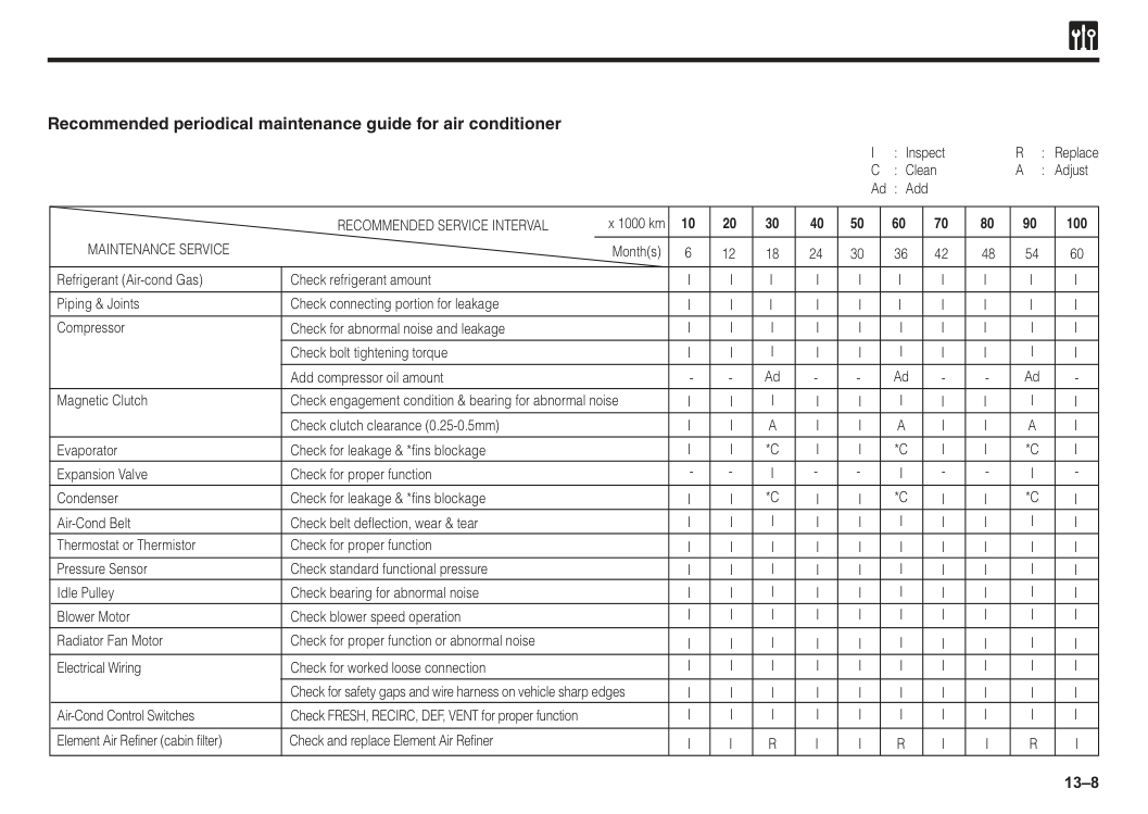
13–8 Recommended periodical maintenance guide for air conditioner
Maintenance Service
Recommended Service Interval
x 1000 km 10 6 20 30 12 18 24 30 36 42 48 54 60 40 50 60 70 80 90 100 Month(s)I
: InspectR
: ReplaceC
: CleanA
: Adjust Ad : Add Refrigerant (Air-cond Gas) Check refrigerant amount Evaporator Check for leakage & *fins blockage Expansion Valve Check for proper function Condenser Check for leakage & *fins blockage Air-Cond Belt Check belt deflection, wear & tear Blower Motor Check blower speed operation Radiator Fan Motor Check for proper function or abnormal noise Electrical Wiring Check for worked loose connection Air-Cond Control Switches Element Air Refiner (cabin filter) Check and replace Element Air Refiner Check FRESH, RECIRC, DEF, VENT for proper function Check for safety gaps and wire harness on vehicle sharp edges Magnetic Clutch Check engagement condition & bearing for abnormal noise Piping & Joints Check connecting portion for leakage Compressor Check for abnormal noise and leakage Add compressor oil amount Check bolt tightening torque Check clutch clearance (0.25-0.5mm) Thermostat or Thermistor Pressure Sensor Idle Pulley Check for proper function Check standard functional pressure Check bearing for abnormal noiseI
I
A
*C
*C
R
AdI
I
I
I
I
I
I
I
I
I
R
I
I
I
A
*C
*C
AdI
I
I
I
I
A
*C
*C
R
AdI
I
I
I
I
I
I
I
I
I
I
I
I
I
I
I
I
I
I
I
I
I
I
I
I
I
I
I
I
I
I
I
I
I
I
I
I
I
I
I
I
I
I
I
I
I
I
I
I
I
I
I
I
I
I
I
I
I
I
I
I
I
I
I
I
I
I
I
I
I
I
I
I
I
I
I
I
I
I
I
I
I
I
I
I
I
I
I
I
I
I
I
I
I
I
I
I
I
I
I
I
I
I
I
I
I
I
I
I
I
I
I
I
I
I
I
I
I
I
I
I
I
I
I
I
I
I
I
I
I
I
I
I
I
I
I
I
I
I
I
I
I
I
I
I
I
I
I
I
I
I
14 Engine compartment..............................................................................................................................14-1 Instruction on do-it-yourself maintenance service.............................................................................14-3 Engine oil................................................................................................................................................14-4 Engine coolant........................................................................................................................................14-7 Drive belt check......................................................................................................................................14-9 Air filter cleaning and replacement.......................................................................................................14-10 Spark plug check and replacement......................................................................................................14-11 Battery condition check and cleaning..................................................................................................14-15 Fuse.........................................................................................................................................................14-17 Fusible link check...................................................................................................................................14-22 Brake fluid level check...........................................................................................................................14-22 Windshield washer fluid level check.....................................................................................................14-23 Manual transmission oil level check.....................................................................................................14-24 Automatic transmission fluid level check............................................................................................14-24 Steering wheel free play check.............................................................................................................14-25 Clutch pedal free play check.................................................................................................................14-26 Brake pedal.............................................................................................................................................14-26 Parking brake reserve travel check.......................................................................................................14-27 Brake booster operation check.............................................................................................................14-28 Wiper blade replacement.......................................................................................................................14-28 Light bulb replacement..........................................................................................................................14-30 Tyres........................................................................................................................................................14-37 Section 14 Do-it-yourself maintenance service
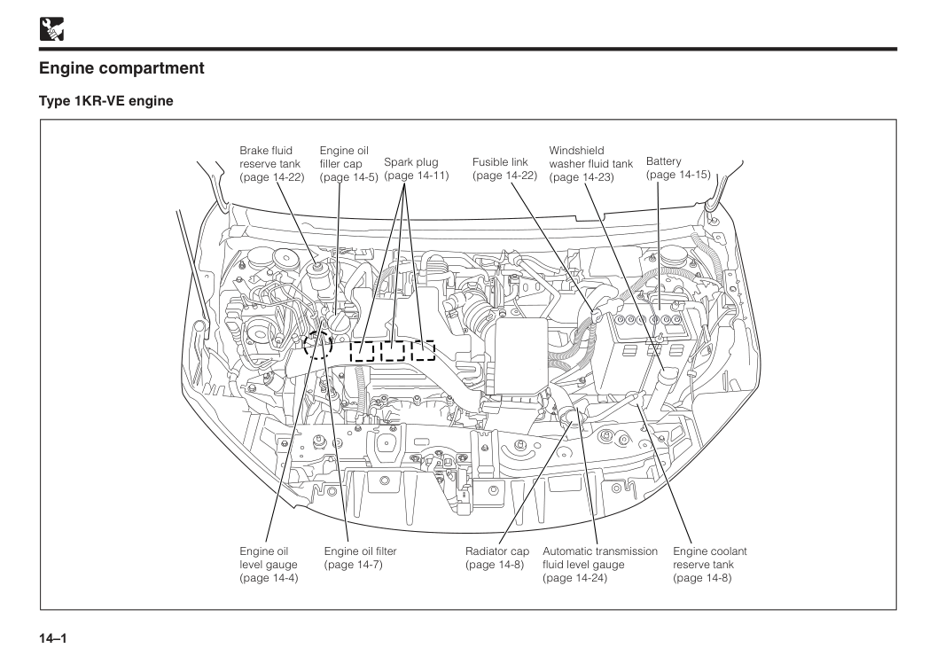
14–1 Engine compartment Type 1KR-VE engine Radiator cap (page 14-8) Engine oil filter (page 14-7) Engine oil level gauge (page 14-4) Brake fluid reserve tank (page 14-22) Engine oil filler cap (page 14-5) Spark plug (page 14-11) Fusible link (page 14-22) Battery (page 14-15) Windshield washer fluid tank (page 14-23) Engine coolant reserve tank (page 14-8) Automatic transmission fluid level gauge (page 14-24)
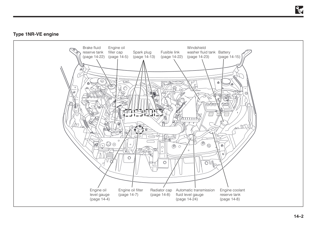
14–2 Type 1NR-VE engine Brake fluid reserve tank (page 14-22) Spark plug (page 14-13) Fusible link (page 14-22) Battery (page 14-15) Windshield washer fluid tank (page 14-23) Engine oil filler cap (page 14-5) Engine coolant reserve tank (page 14-8) Automatic transmission fluid level gauge (page 14-24) Radiator cap (page 14-8) Engine oil filter (page 14-7) Engine oil level gauge (page 14-4)
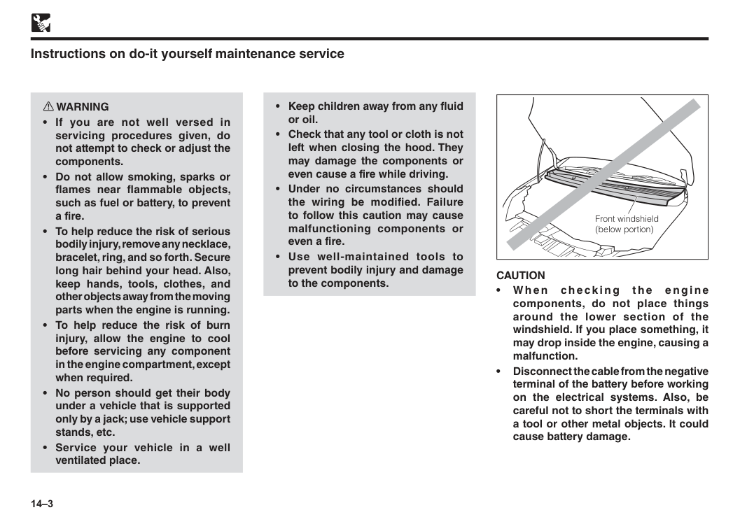
14–3 w WARNING
Caution
• W h e n ch e ck i n g t h e e n g i n e components, do not place things around the lower section of the windshield. If you place something, it may drop inside the engine, causing a malfunction. • Disconnect the cable from the negative terminal of the battery before working on the electrical systems. Also, be careful not to short the terminals with a tool or other metal objects. It could cause battery damage.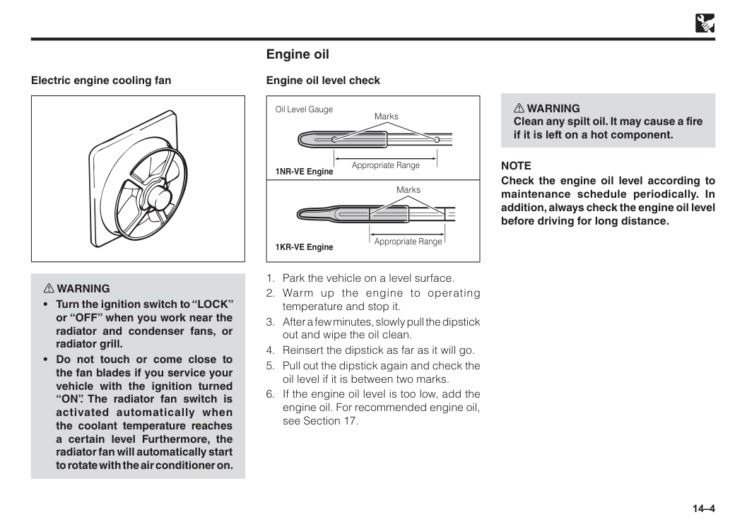
14–4 Electric engine cooling fan w WARNING
Note
Check the engine oil level according to maintenance schedule periodically. In addition, always check the engine oil level before driving for long distance.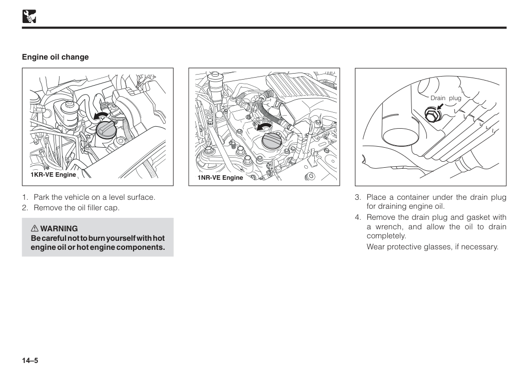
14–5
Wear protective glasses, if necessary. Drain plug
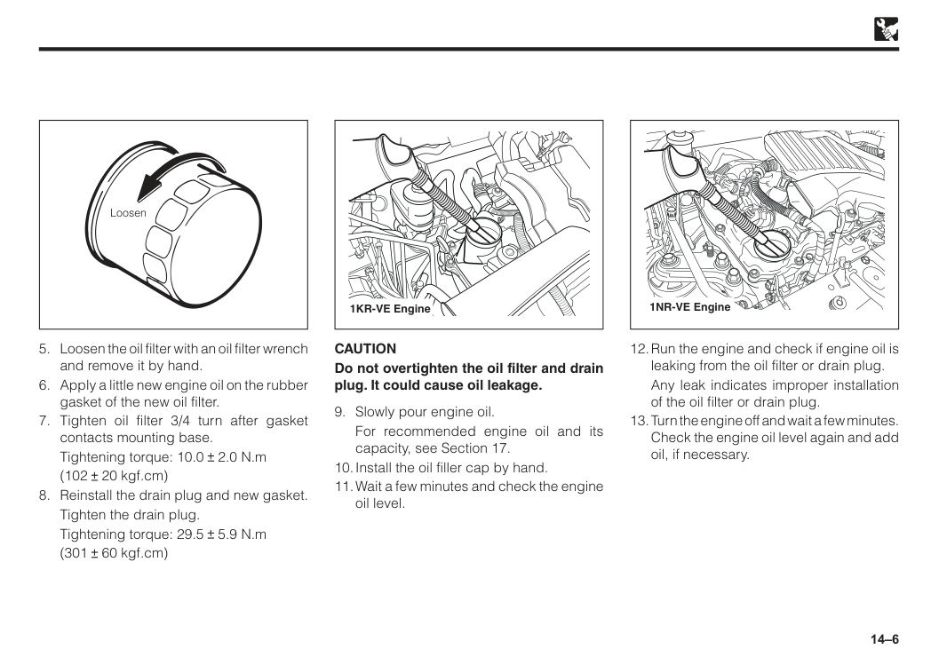
14–6 Loosen
Tightening torque: 10.0 2.0 N.m
(102 20 kgf.cm)
Tighten the drain plug.
Tightening torque: 29.5 5.9 N.m
(301 60 kgf.cm)
Caution
Do not overtighten the oil filter and drain plug. It could cause oil leakage.For recommended engine oil and its capacity, see Section 17.
Any leak indicates improper installation of the oil filter or drain plug.
14–7 w WARNING
Caution
Use only Perodua genuine oil filter for your Perodua. When it needs to be replaced, be sure to replace it at the authorised Perodua Service Centre. Engine coolant w WARNING Be careful not to burn yourself when removing the radiator cap or drain plug.Caution
• Follow the coolant manufacturer’s instructions. • To prevent aluminum corrosion, be sure to use a high-quality corrosion protection type (ethylene glycol base) long-life coolant. • As for the coolant concentration, keep it at ratio of 40% coolant and 60% soft water or demineralized water (reverse osmosis or distilled water). If coolant level decreases noticeably, have the cooling system checked by an authorised Perodua Service Centre.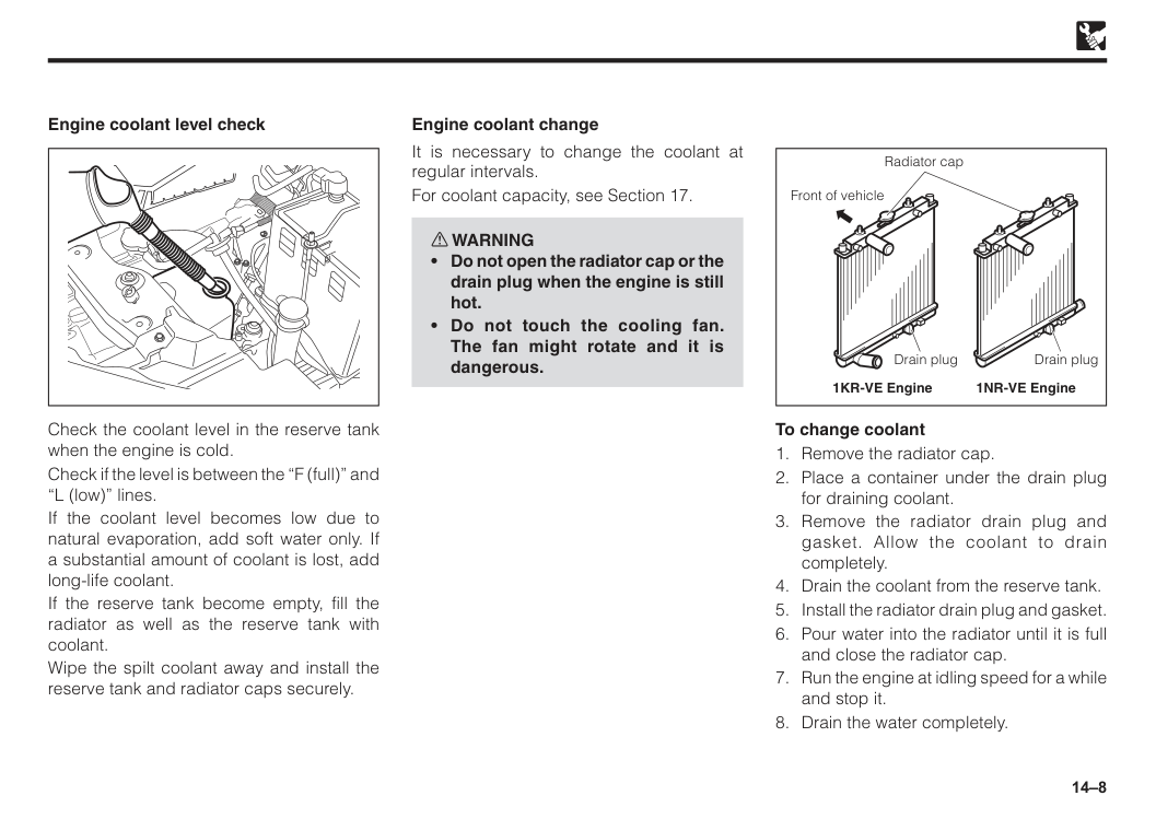
14–8 Check the coolant level in the reserve tank when the engine is cold. Check if the level is between the “F (full)” and “L (low)” lines. If the coolant level becomes low due to natural evaporation, add soft water only. If a substantial amount of coolant is lost, add long-life coolant. If the reserve tank become empty, fill the radiator as well as the reserve tank with coolant. Wipe the spilt coolant away and install the reserve tank and radiator caps securely. Engine coolant level check It is necessary to change the coolant at regular intervals. For coolant capacity, see Section 17. w WARNING
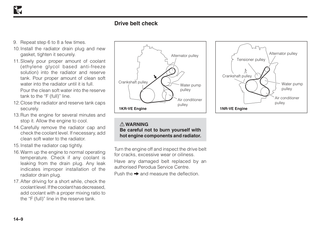
14–9
Pour the clean soft water into the reserve tank to the “F (full)” line.
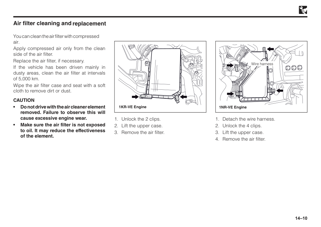
14–10 • Do not drive with the air cleaner element removed. Failure to observe this will cause excessive engine wear. • Make sure the air filter is not exposed to oil. It may reduce the effectiveness of the element. Air filter cleaning and You can clean the air filter with compressed air. Apply compressed air only from the clean side of the air filter. Replace the air filter, if necessary. If the vehicle has been driven mainly in dusty areas, clean the air filter at intervals of 5,000 km. Wipe the air filter case and seat with a soft cloth to remove dirt or dust.
Caution
1KR-VE Engine 1NR-VE Engine Wire harness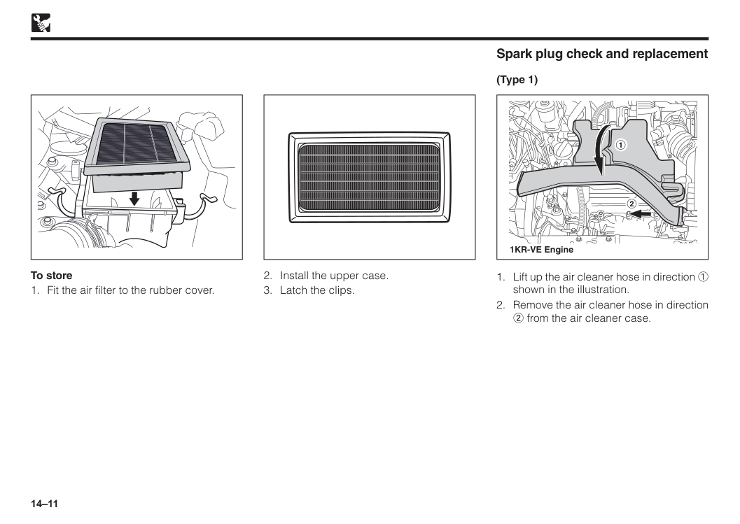
14–11 To store
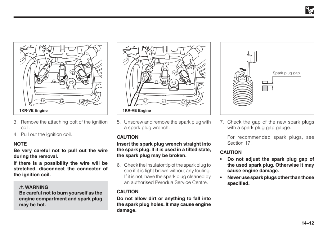
14–12 1KR-VE Engine
Note
Be very careful not to pull out the wire during the removal. If there is a possibility the wire will be stretched, disconnect the connector of the ignition coil. w WARNING Be careful not to burn yourself as the engine compartment and spark plug may be hot.Caution
Insert the spark plug wrench straight into the spark plug. If it is used in a tilted state, the spark plug may be broken.Caution
Do not allow dirt or anything to fall into the spark plug holes. It may cause engine damage. 1KR-VE EngineFor recommended spark plugs, see Section 17.
Caution
• Do not adjust the spark plug gap of the used spark plug. Otherwise it may cause engine damage. • Never use spark plugs other than those specified. Spark plug gap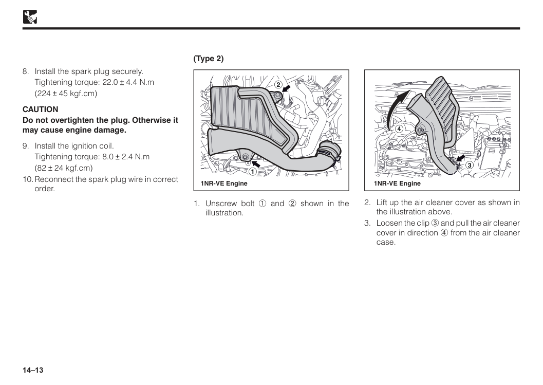
14–13 (Type 2) 2 1 1NR-VE Engine 4 3 1NR-VE Engine
Tightening torque: 22.0 4.4 N.m
(224 45 kgf.cm)
Caution
Do not overtighten the plug. Otherwise it may cause engine damage.Tightening torque: 8.0 2.4 N.m
(82 24 kgf.cm)
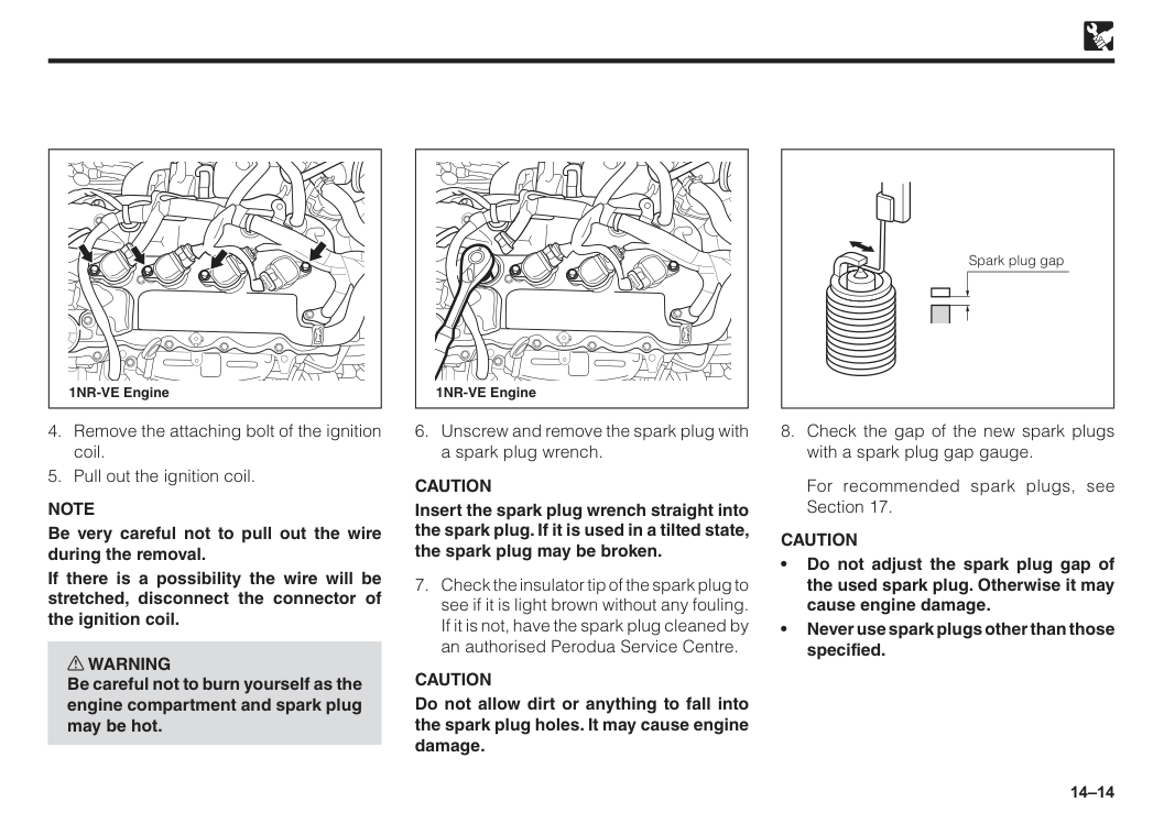
14–14 1NR-VE Engine 1NR-VE Engine
Note
Be very careful not to pull out the wire during the removal. If there is a possibility the wire will be stretched, disconnect the connector of the ignition coil. w WARNING Be careful not to burn yourself as the engine compartment and spark plug may be hot.Caution
Insert the spark plug wrench straight into the spark plug. If it is used in a tilted state, the spark plug may be broken.Caution
Do not allow dirt or anything to fall into the spark plug holes. It may cause engine damage.For recommended spark plugs, see Section 17.
Caution
• Do not adjust the spark plug gap of the used spark plug. Otherwise it may cause engine damage. • Never use spark plugs other than those specified. Spark plug gap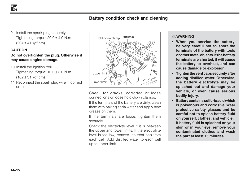
14–15 Upper limit Lower limit Terminals Hold down clamp Battery condition check and cleaning Check for cracks, corroded or loose connections or loose hold-down clamps. If the terminals of the battery are dirty, clean them with baking soda water and apply new grease on them. If the terminals are loose, tighten them securely. Check the electrolyte level if it is between the upper and lower limits. If the electrolyte level is too low, remove the vent cap from each cell. Add distilled water to each cell up to upper limit. w WARNING
Caution
Do not overtighten the plug. Otherwise it may cause engine damage.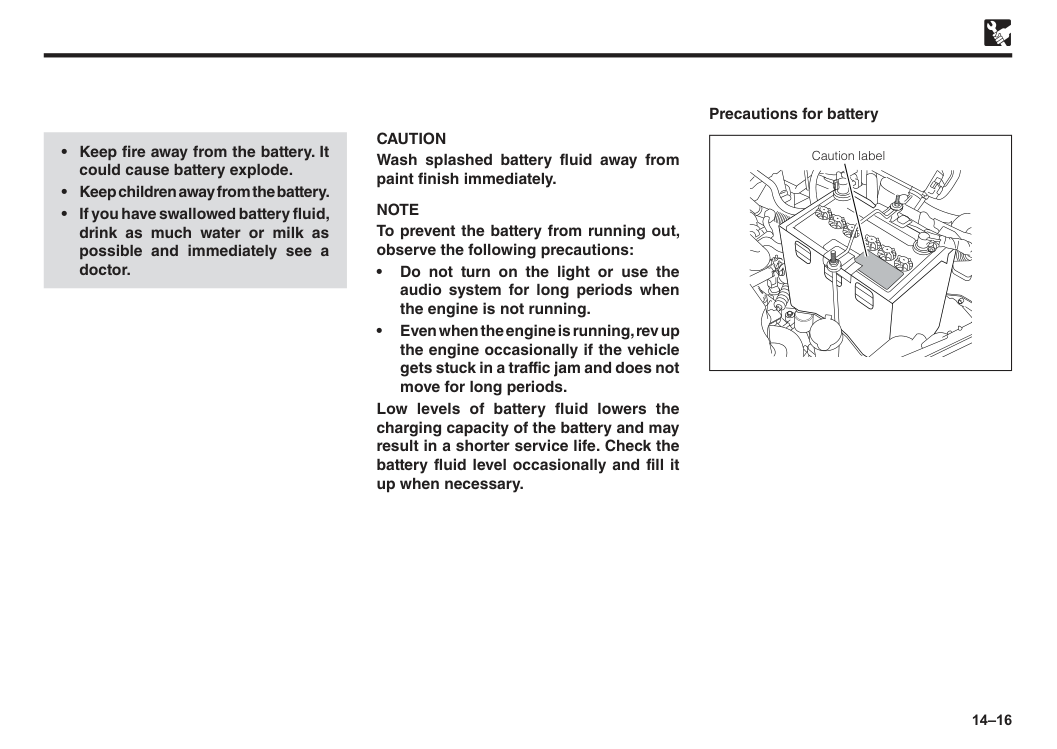
14–16
Caution
Wash splashed battery fluid away from paint finish immediately.Note
To prevent the battery from running out, observe the following precautions: • Do not turn on the light or use the audio system for long periods when the engine is not running. • Even when the engine is running, rev up the engine occasionally if the vehicle gets stuck in a traffic jam and does not move for long periods. Low levels of battery fluid lowers the charging capacity of the battery and may result in a shorter service life. Check the battery fluid level occasionally and fill it up when necessary. Precautions for battery Caution label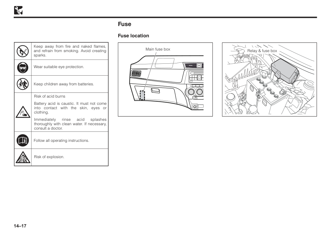
14–17 Risk of explosion. Risk of acid burns Battery acid is caustic. It must not come into contact with the skin, eyes or clothing. Immediately rinse acid splashes thoroughly with clean water. If necessary, consult a doctor. Keep away from fire and naked flames, and refrain from smoking. Avoid creating sparks. Wear suitable eye protection. Follow all operating instructions. Keep children away from batteries. Fuse Fuse location Main fuse box Relay & fuse box
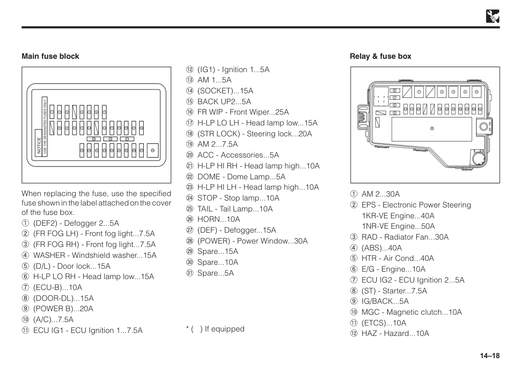
14–18 Main fuse block 1
Notice
Use The Designated Fuses Only
2 3 4 5 6 7 8 20 19 18 17 16 15 14 12 13 21 22 23 24 25 26 27 28 31 29 30 11 10 9 When replacing the fuse, use the specified fuse shown in the label attached on the cover of the fuse box. 1 (DEF2) - Defogger 2...5A 2 (FR FOG LH) - Front fog light...7.5A 3 (FR FOG RH) - Front fog light...7.5A 4 WASHER - Windshield washer...15A 5 (D/L) - Door lock...15A 6 H-LP LO RH - Head lamp low...15A7 (Ecu-B)...10A
8 (Door-Dl)...15A
9 (Power B)...20A
! (A/C)...7.5A
" ECU IG1 - ECU Ignition 1...7.5A Relay & fuse box 17 18 19 20 16 15 14 13 12 11 10 9 8 7 6 1 2 3 4 51 Am 2...30A
2 EPS - Electronic Power Steering1KR-VE Engine...40A
1NR-VE Engine...50A 3 RAD - Radiator Fan...30A
4 (Abs)...40A
5 HTR - Air Cond...40A 6 E/G - Engine...10A 7 ECU IG2 - ECU Ignition 2...5A 8 (ST) - Starter...7.5A9 Ig/Back...5A
! MGC - Magnetic clutch...10A" (Etcs)...10A
# HAZ - Hazard...10A # (IG1) - Ignition 1...5A$ Am 1...5A
% (Socket)...15A
& Back Up2...5A
' FR WIP - Front Wiper...25A ( H-LP LO LH - Head lamp low...15A ) (STR LOCK) - Steering lock...20A* Am 2...7.5A
+ ACC - Accessories...5A , H-LP HI RH - Head lamp high...10AÇ Horn...10A
É (DEF) - Defogger...15A Ñ (POWER) - Power Window...30A Ö Spare...15A Ü Spare...10A á Spare...5A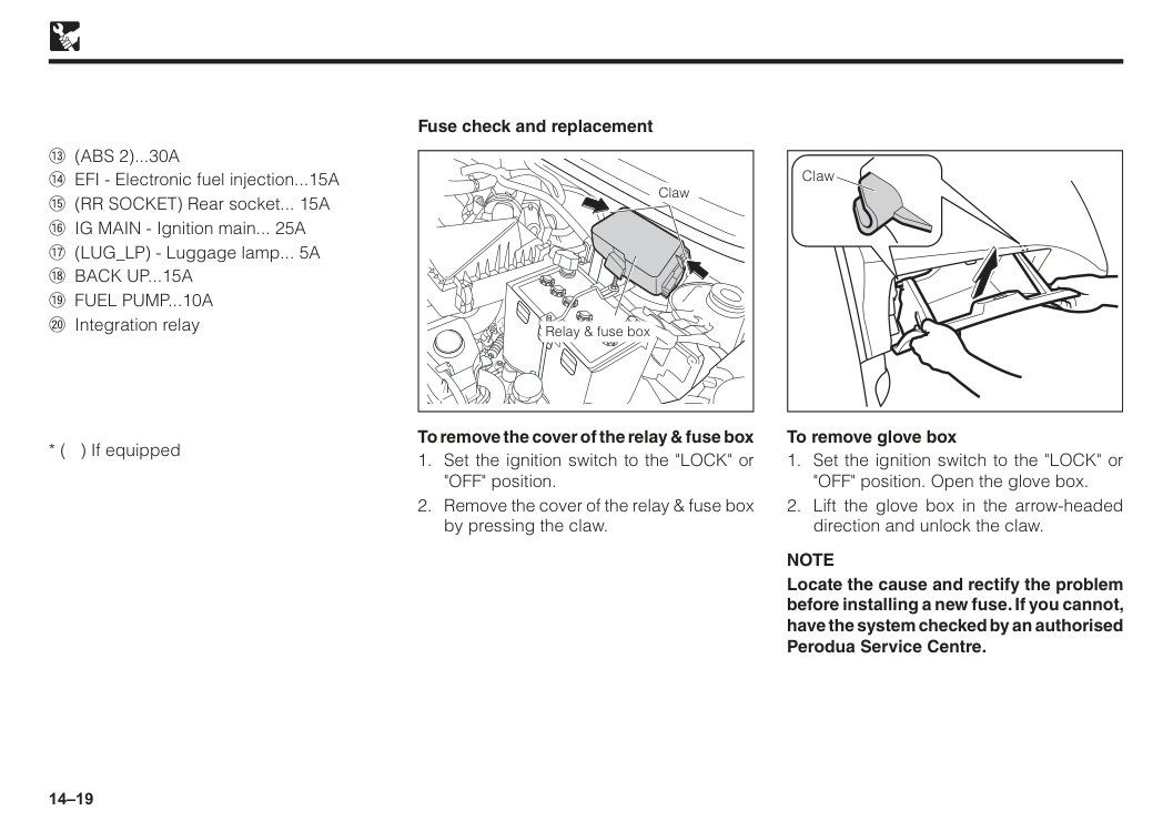
14–19 Fuse check and replacement Claw Relay & fuse box To remove the cover of the relay & fuse box
Note
Locate the cause and rectify the problem before installing a new fuse. If you cannot, have the system checked by an authorised Perodua Service Centre. Claw$ (Abs 2)...30A
% EFI - Electronic fuel injection...15A & (RR SOCKET) Rear socket... 15A ' IG MAIN - Ignition main... 25A ( (LUG_LP) - Luggage lamp... 5A) Back Up...15A
* Fuel Pump...10A
+ Integration relay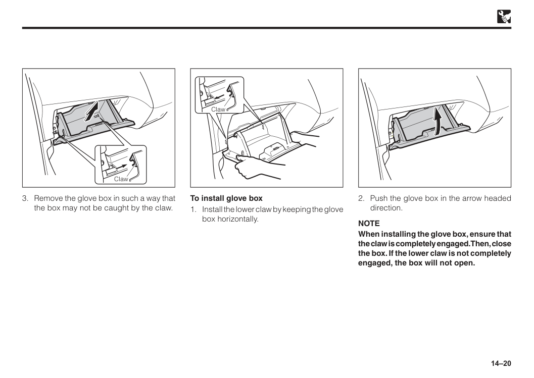
14–20
Note
When installing the glove box, ensure that the claw is completely engaged. Then, close the box. If the lower claw is not completely engaged, the box will not open. Claw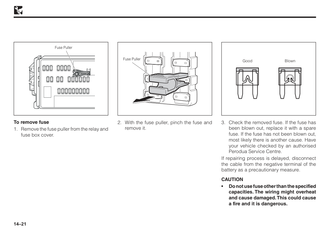
14–21 To remove fuse
Caution
• Do not use fuse other than the specified capacities. The wiring might overheat and cause damaged. This could cause a fire and it is dangerous. Good Blown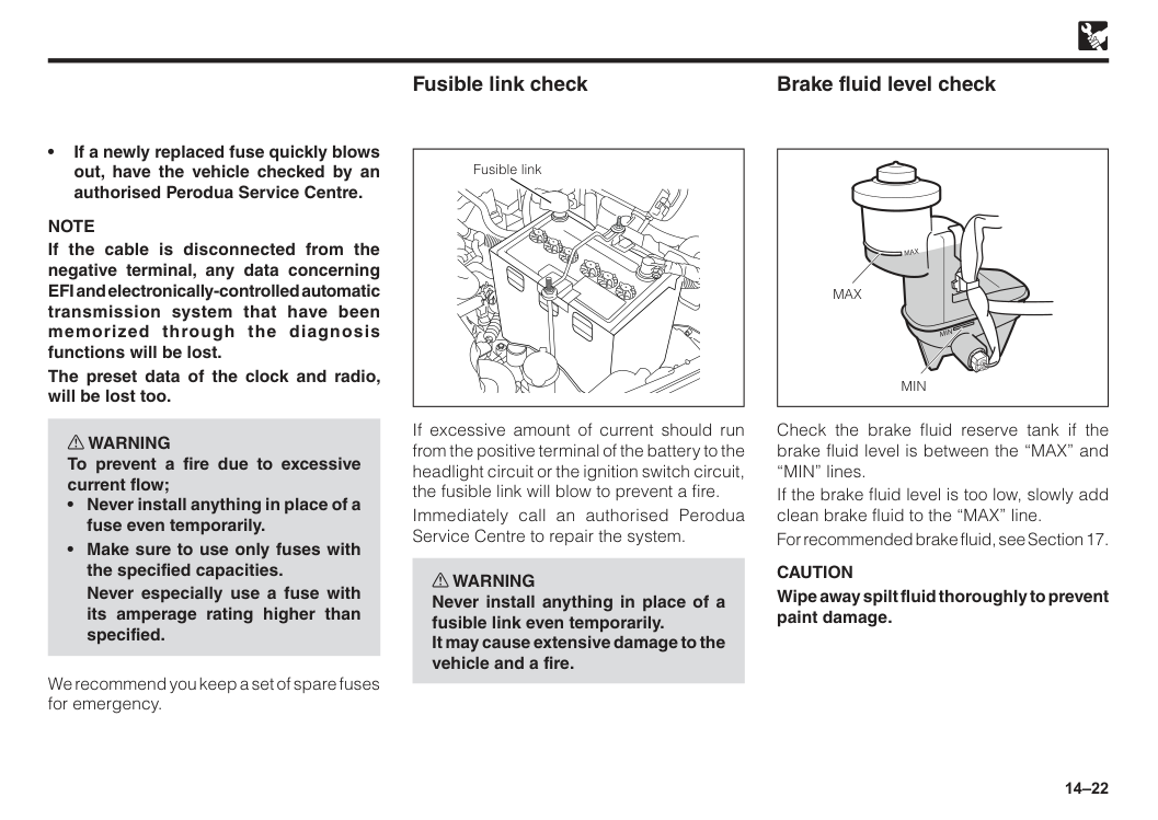
14–22 • If a newly replaced fuse quickly blows out, have the vehicle checked by an authorised Perodua Service Centre.
Note
If the cable is disconnected from the negative terminal, any data concerning EFI and electronically-controlled automatic transmission system that have been memorized through the diagnosis functions will be lost. The preset data of the clock and radio, will be lost too. w WARNING To prevent a fire due to excessive current flow;Never especially use a fuse with its amperage rating higher than specified. We recommend you keep a set of spare fuses for emergency. Fusible link check If excessive amount of current should run from the positive terminal of the battery to the headlight circuit or the ignition switch circuit, the fusible link will blow to prevent a fire. Immediately call an authorised Perodua Service Centre to repair the system. w WARNING Never install anything in place of a fusible link even temporarily. It may cause extensive damage to the vehicle and a fire. Fusible link Check the brake fluid reserve tank if the brake fluid level is between the “MAX” and “MIN” lines. If the brake fluid level is too low, slowly add clean brake fluid to the “MAX” line. For recommended brake fluid, see Section 17.
Caution
Wipe away spilt fluid thoroughly to prevent paint damage. Brake fluid level checkMin
Max
Max
Min
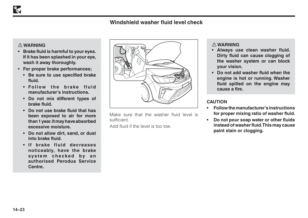
14–23 Windshield washer fluid level check Make sure that the washer fluid level is sufficient. Add fluid if the level is too low. w WARNING
Caution
• Follow the manufacturer’s instructions for proper mixing ratio of washer fluid. • Do not pour soap water or other fluids instead of washer fluid. This may cause paint stain or clogging.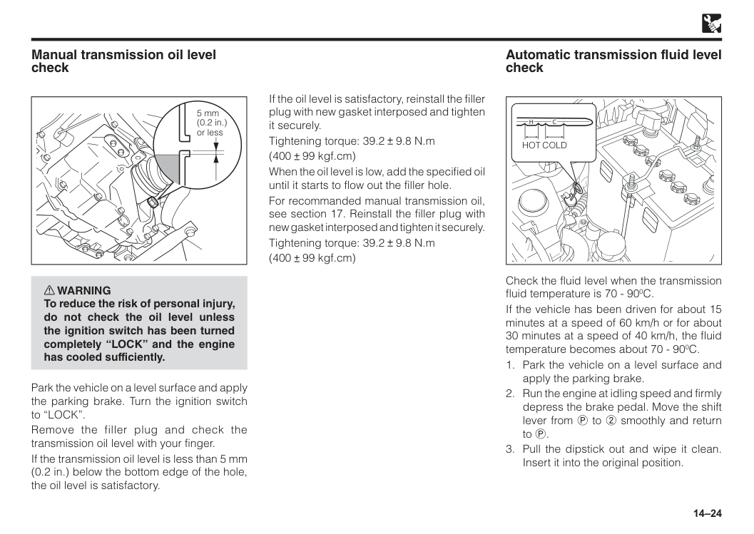
14–24 w WARNING To reduce the risk of personal injury, do not check the oil level unless the ignition switch has been turned completely “LOCK” and the engine has cooled sufficiently. Park the vehicle on a level surface and apply the parking brake. Turn the ignition switch to “LOCK”. Remove the filler plug and check the transmission oil level with your finger. If the transmission oil level is less than 5 mm (0.2 in.) below the bottom edge of the hole, the oil level is satisfactory. 5 mm (0.2 in.) or less Manual transmission oil level check If the oil level is satisfactory, reinstall the filler plug with new gasket interposed and tighten it securely. Tightening torque: 39.2 9.8 N.m (400 99 kgf.cm) When the oil level is low, add the specified oil until it starts to flow out the filler hole. For recommanded manual transmission oil, see section 17. Reinstall the filler plug with new gasket interposed and tighten it securely. Tightening torque: 39.2 9.8 N.m (400 99 kgf.cm)
Cold
Hot
H
C
Check the fluid level when the transmission fluid temperature is 70 - 900C. If the vehicle has been driven for about 15 minutes at a speed of 60 km/h or for about 30 minutes at a speed of 40 km/h, the fluid temperature becomes about 70 - 900C.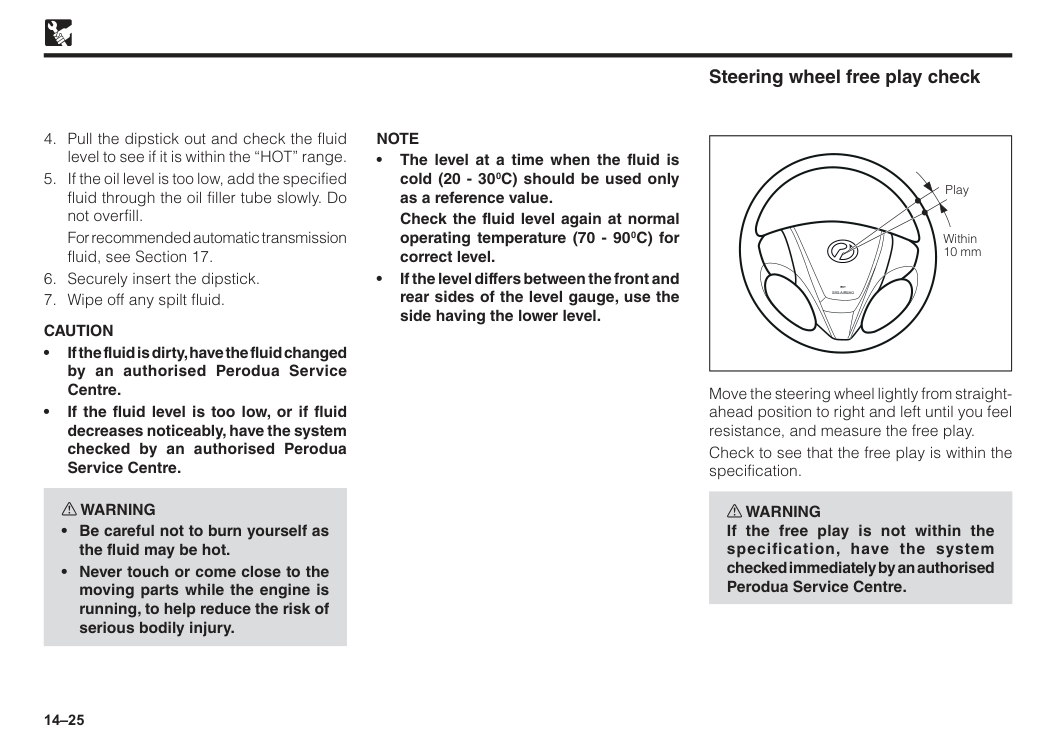
14–25
For recommended automatic transmission fluid, see Section 17.
Caution
• If the fluid is dirty, have the fluid changed by an authorised Perodua Service Centre. • If the fluid level is too low, or if fluid decreases noticeably, have the system checked by an authorised Perodua Service Centre. w WARNINGNote
• The level at a time when the fluid is cold (20 - 300C) should be used only as a reference value.Check the fluid level again at normal operating temperature (70 - 900C) for correct level. • If the level differs between the front and rear sides of the level gauge, use the side having the lower level.
Srs Airbag
Play Within 10 mm Steering wheel free play check Move the steering wheel lightly from straight- ahead position to right and left until you feel resistance, and measure the free play. Check to see that the free play is within the specification. w WARNING If the free play is not within the specification, have the system checked immediately by an authorised Perodua Service Centre.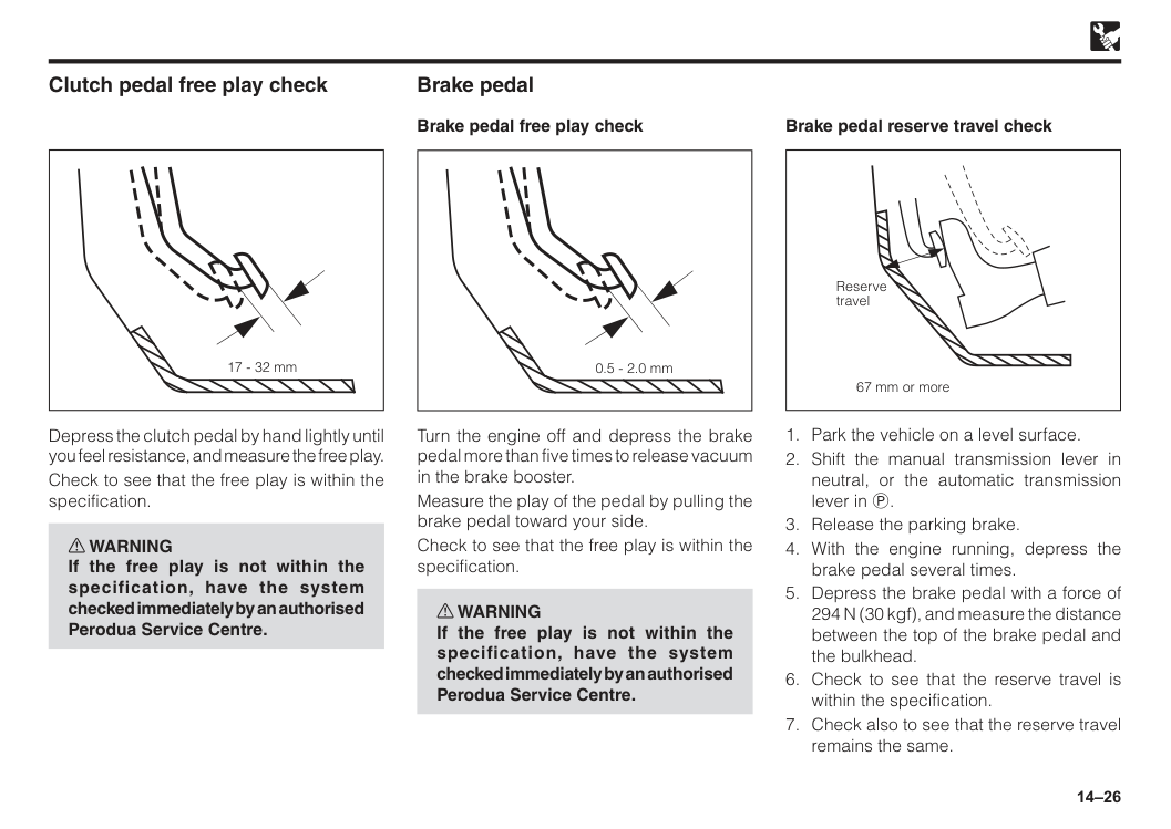
14–26 17 - 32 mm Clutch pedal free play check Depress the clutch pedal by hand lightly until you feel resistance, and measure the free play. Check to see that the free play is within the specification. w WARNING If the free play is not within the specification, have the system checked immediately by an authorised Perodua Service Centre. 0.5 - 2.0 mm Turn the engine off and depress the brake pedal more than five times to release vacuum in the brake booster. Measure the play of the pedal by pulling the brake pedal toward your side. Check to see that the free play is within the specification. w WARNING If the free play is not within the specification, have the system checked immediately by an authorised Perodua Service Centre. Brake pedal Brake pedal free play check 67 mm or more Reserve travel Brake pedal reserve travel check
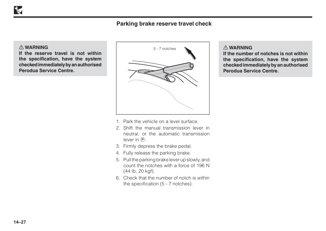
14–27 w WARNING If the reserve travel is not within the specification, have the system checked immediately by an authorised Perodua Service Centre. 5 - 7 notches
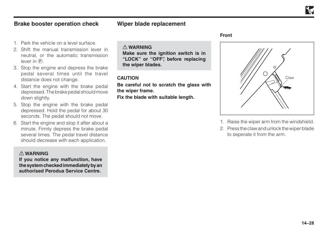
14–28
Caution
Be careful not to scratch the glass with the wiper frame. Fix the blade with suitable length. Wiper blade replacement Claw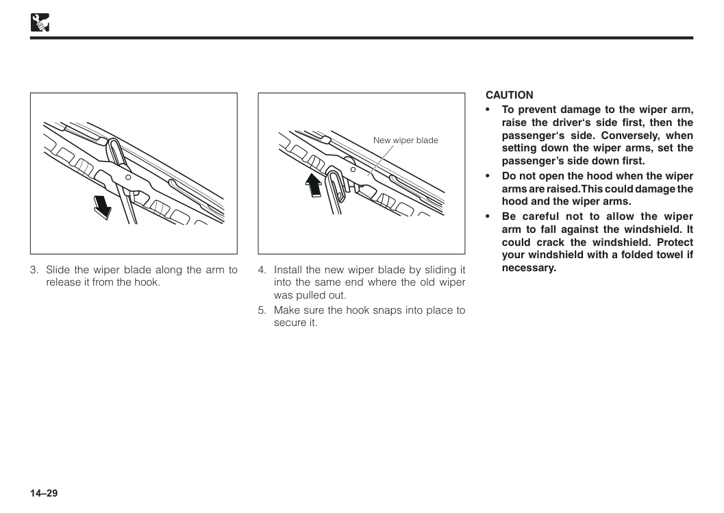
14–29 New wiper blade
Caution
• To prevent damage to the wiper arm, raise the driver‘s side first, then the passenger‘s side. Conversely, when setting down the wiper arms, set the passenger’s side down first. • Do not open the hood when the wiper arms are raised. This could damage the hood and the wiper arms. • Be careful not to allow the wiper arm to fall against the windshield. It could crack the windshield. Protect your windshield with a folded towel if necessary.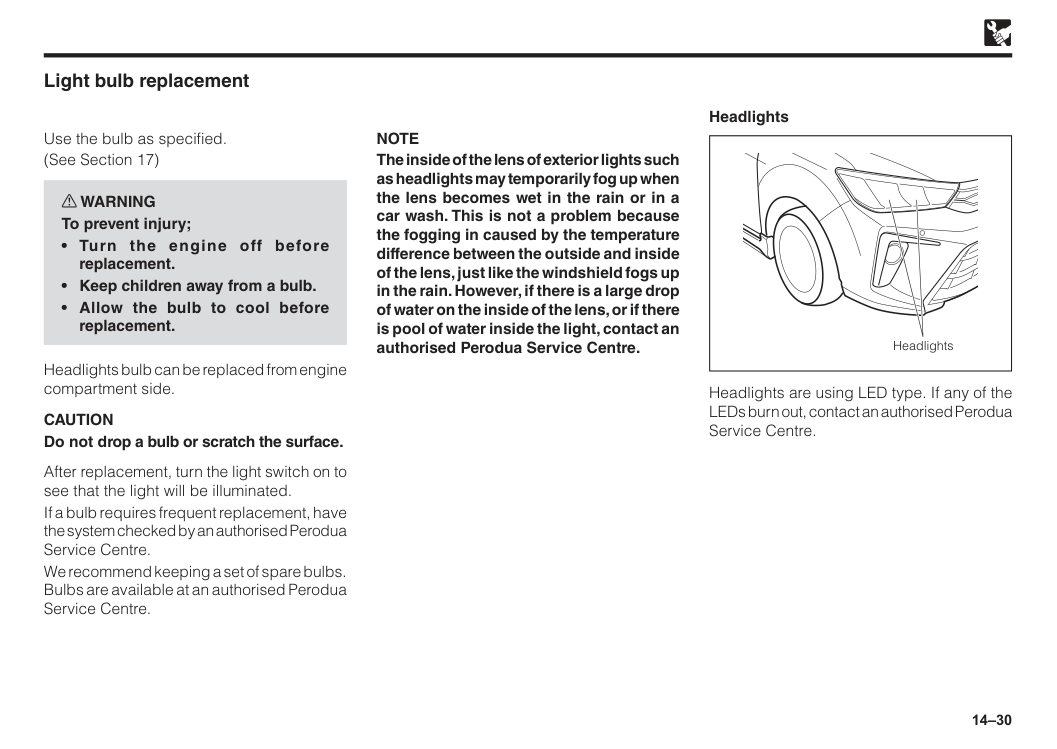
14–30 Light bulb replacement Use the bulb as specified. (See Section 17) w WARNING To prevent injury;
Caution
Do not drop a bulb or scratch the surface. After replacement, turn the light switch on to see that the light will be illuminated. If a bulb requires frequent replacement, have the system checked by an authorised Perodua Service Centre. We recommend keeping a set of spare bulbs. Bulbs are available at an authorised Perodua Service Centre.Note
The inside of the lens of exterior lights such as headlights may temporarily fog up when the lens becomes wet in the rain or in a car wash. This is not a problem because the fogging in caused by the temperature difference between the outside and inside of the lens, just like the windshield fogs up in the rain. However, if there is a large drop of water on the inside of the lens, or if there is pool of water inside the light, contact an authorised Perodua Service Centre. Headlights Headlights are using LED type. If any of the LEDs burn out, contact an authorised Perodua Service Centre. Headlights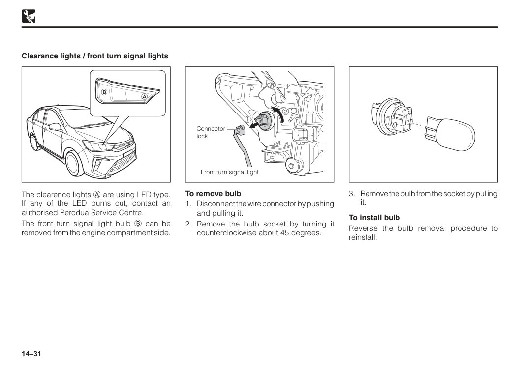
14–31 Clearance lights / front turn signal lights The clearence lights A are using LED type. If any of the LED burns out, contact an authorised Perodua Service Centre. The front turn signal light bulb B can be removed from the engine compartment side. To remove bulb
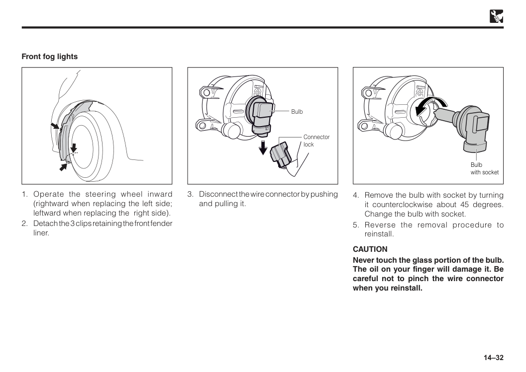
14–32 Connector lock Bulb
Caution
Never touch the glass portion of the bulb. The oil on your finger will damage it. Be careful not to pinch the wire connector when you reinstall.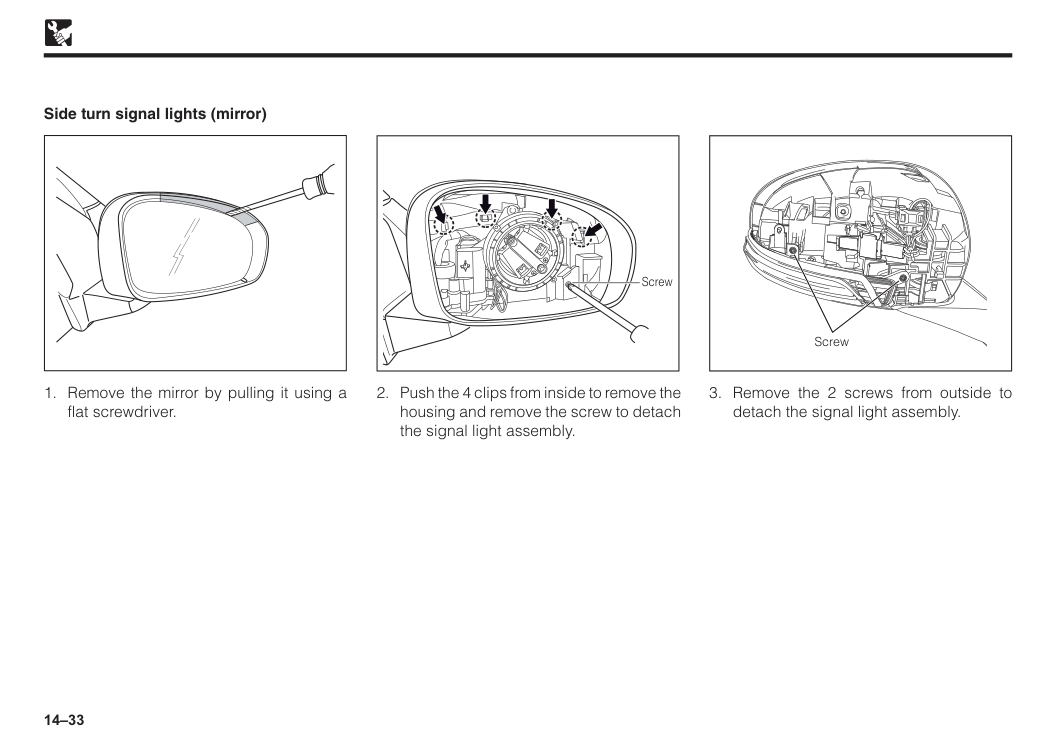
14–33
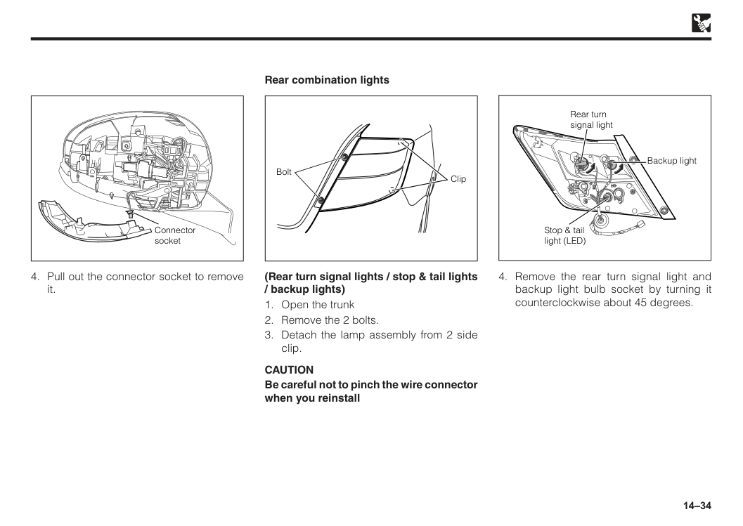
14–34 Connector socket
Caution
Be careful not to pinch the wire connector when you reinstall Bolt Clip Rear combination lights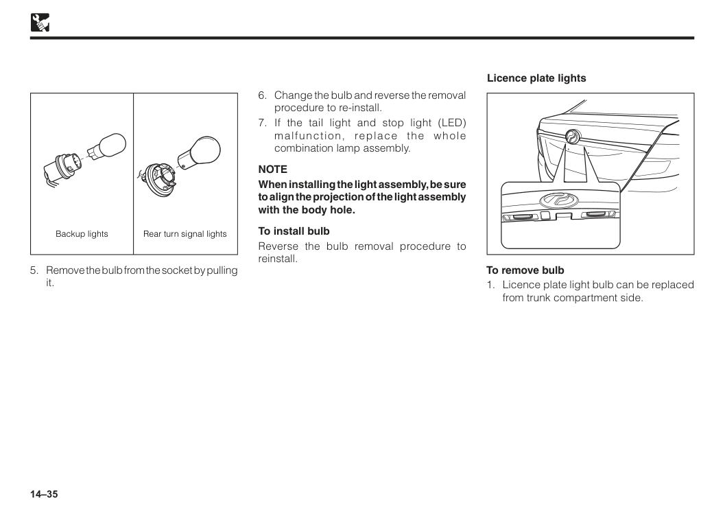
14–35
Note
When installing the light assembly, be sure to align the projection of the light assembly with the body hole. To install bulb Reverse the bulb removal procedure to reinstall. To remove bulb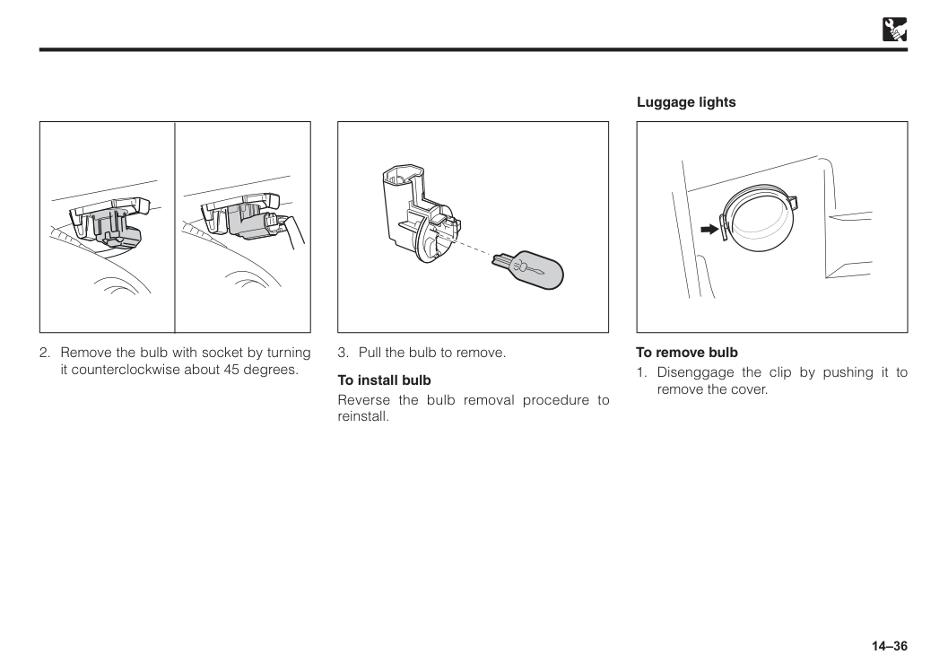
14–36
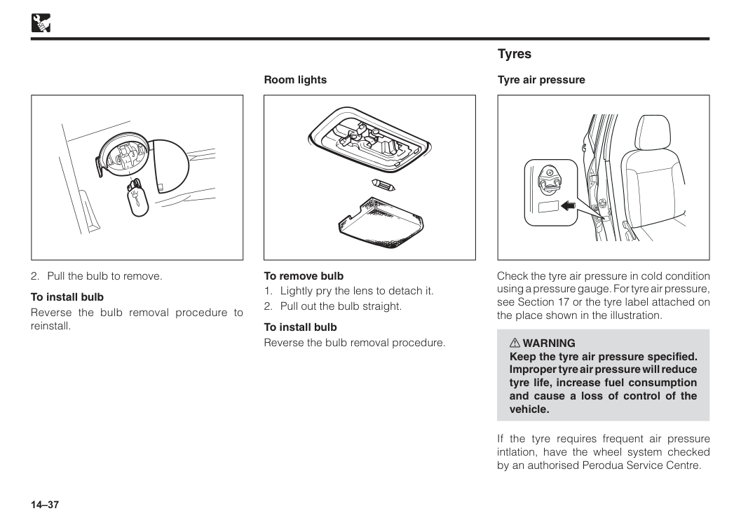
14–37
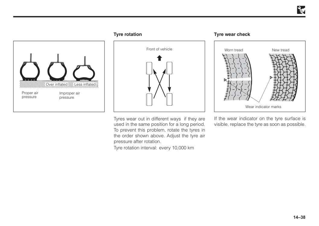
14–38 Proper air pressure Improper air pressure Less inflated Over inflated Tyre rotation Tyres wear out in different ways if they are used in the same position for a long period. To prevent this problem, rotate the tyres in the order shown above. Adjust the tyre air pressure after rotation. Tyre rotation interval: every 10,000 km Front of vehicle If the wear indicator on the tyre surface is visible, replace the tyre as soon as possible. Tyre wear check Worn tread New tread Wear indicator marks
14–39
Caution
Be careful not to damage the tyres by scratching or oiling etc.
15 Introduction.......................................................................................15–1 Car alarm/central lock......................................................................15–1 Panic button......................................................................................15–3 Car finder...........................................................................................15–3 Important...........................................................................................15–3 Replacement of battery in the transmitter......................................15–4 Section 15 Alarm/central locking
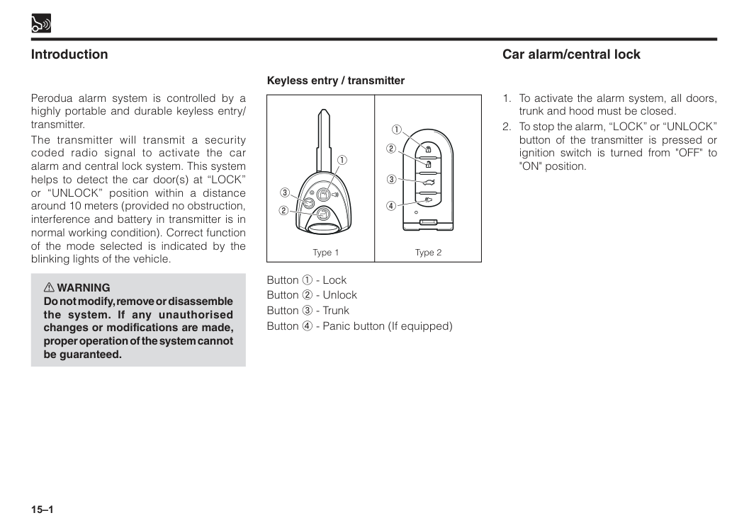
15–1 Introduction Type 1 Type 2 Perodua alarm system is controlled by a highly portable and durable keyless entry/ transmitter. The transmitter will transmit a security coded radio signal to activate the car alarm and central lock system. This system helps to detect the car door(s) at “LOCK” or “UNLOCK” position within a distance around 10 meters (provided no obstruction, interference and battery in transmitter is in normal working condition). Correct function of the mode selected is indicated by the blinking lights of the vehicle. w WARNING Do not modify, remove or disassemble the system. If any unauthorised changes or modifications are made, proper operation of the system cannot be guaranteed. Keyless entry / transmitter Button 1 - Lock Button 2 - Unlock Button 3 - Trunk Button 4 - Panic button (If equipped) Car alarm/central lock
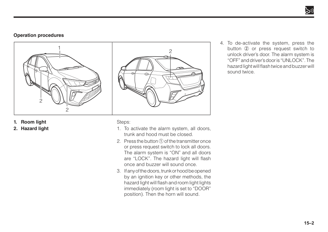
15–2
15–3 To ensure that this system is in good working conditions, always check the followings:
If the battery of the transmitter is weak, it will affect the system as follows: a) The control distance of the transmitter becomes nearer or the transmitter is unable to activate or de-activate the alarm/central lock system.
NOTE: If the above symptoms are detected, the battery must be replaced.
Even if the battery of the transmitter is in good working condition, the control distance may becomes nearer due to the excessive RF interference/harmonic interference (e.g. mobile telephone is in use beside the vehicle; installation of audio devices like car speaker is too close to system control unit) Important This system can help you locate your vehicle in a large car park. You may also use it to ensure that the doors are locked. Operation procedures Steps:
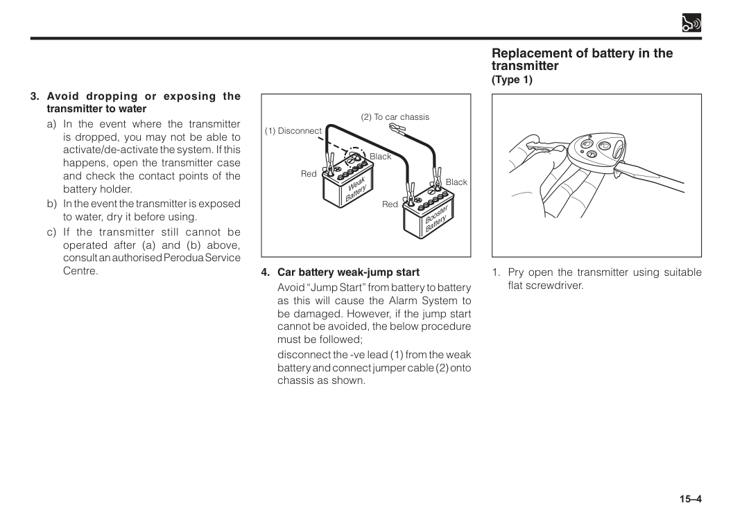
15–4 Booster Battery Weak Battery (1) Disconnect Red Black Red Black (2) To car chassis
Avoid “Jump Start” from battery to battery as this will cause the Alarm System to be damaged. However, if the jump start cannot be avoided, the below procedure must be followed;
disconnect the -ve lead (1) from the weak battery and connect jumper cable (2) onto chassis as shown.
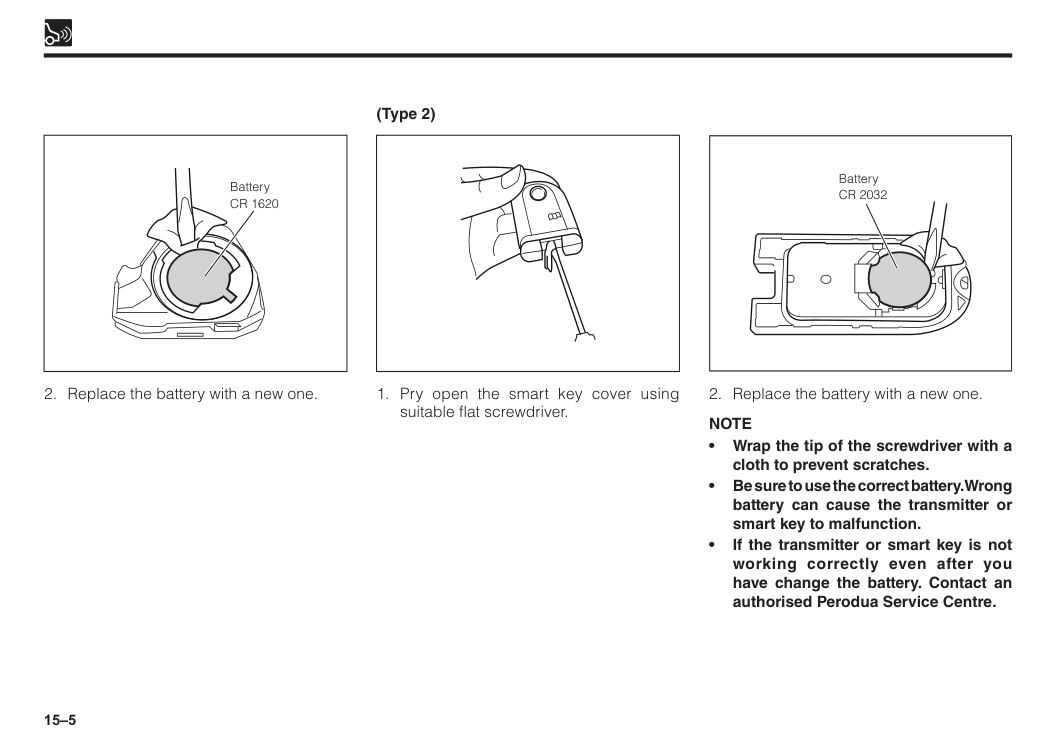
15–5 Battery
Cr 2032
Note
Cr 1620

16 Section 16 Reverse/front corner sensor Reverse sensor.................................................................................16–1 Front corner sensor..........................................................................16–1
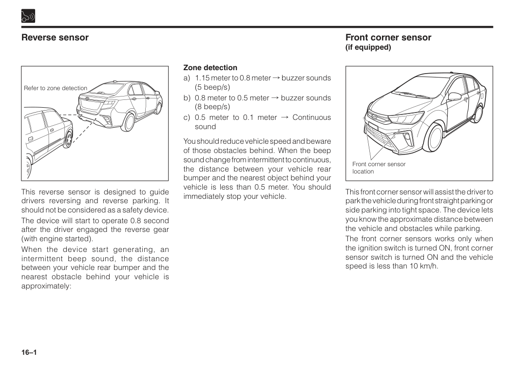
16–1 Reverse sensor Front corner sensor (if equipped) Refer to zone detection Front corner sensor location Zone detection a) 1.15 meter to 0.8 meter ! buzzer sounds (5 beep/s) b) 0.8 meter to 0.5 meter ! buzzer sounds (8 beep/s) c) 0.5 meter to 0.1 meter ! Continuous sound You should reduce vehicle speed and beware of those obstacles behind. When the beep sound change from intermittent to continuous, the distance between your vehicle rear bumper and the nearest object behind your vehicle is less than 0.5 meter. You should immediately stop your vehicle. This reverse sensor is designed to guide drivers reversing and reverse parking. It should not be considered as a safety device. The device will start to operate 0.8 second after the driver engaged the reverse gear (with engine started). When the device start generating, an intermittent beep sound, the distance between your vehicle rear bumper and the nearest obstacle behind your vehicle is approximately: This front corner sensor will assist the driver to park the vehicle during front straight parking or side parking into tight space. The device lets you know the approximate distance between the vehicle and obstacles while parking. The front corner sensors works only when the ignition switch is turned ON, front corner sensor switch is turned ON and the vehicle speed is less than 10 km/h.
16–2
Caution
• System for detection area is based on vehicle condition and covered area of the vehicle.There is a possibility for this system to fail to detect the above condition. • There is a possibility that the sensor will function abnormally if it is subjected to a hard impact. • Object that are located too close to the center of the bottom of the bumper or close to a tyre cover may also be hard to detect by the sensor. • Presence of dirt or mud around the sensor will cause the sensor to function abnormally and leads to the failure of detecting objects. • If the object is thin or flat, there is a possibility that the object can be detected at first time, but not the second time. • According to the condition such as holes, bumpy road, sands on the road, hills, slope road and bushes area, this system has a tolerance in functioning.Warning
Note
The sensor will automatically “cut-off” when the speed exceeds 10 km/h.
17 Vehicle specifications......................................................................17–1 Engine specifications.......................................................................17–1 Fuel....................................................................................................17–1 Coolant..............................................................................................17–1 Battery...............................................................................................17–1 Engine tune-up.................................................................................17–2 Lubricant recommendation.............................................................17–3 Engine oil viscosity chart................................................................17–3 Brake fluid.........................................................................................17–4 Tyre specifications...........................................................................17–4 Bulb specifications...........................................................................17–4 Weights..............................................................................................17–4 Section 17 Specifications
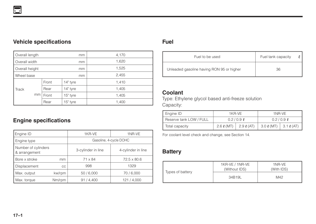
17–1 Vehicle specifications mm mm mm mm mm Overall length 4,170 1,620 1,525 2,455 1,410 1,405 1,405 1,400 Overall width Overall height Wheel base Front Rear Front Rear 14" tyre 14" tyre 15" tyre 15" tyre Track Engine specifications Engine ID
1Kr-Ve
Gasoline, 4-cycle DOHC 3-cylinder in line Engine type Number of cylinders & arrangement Bore x stroke Displacement cc mm Max. output kw/rpm Max. torque Nm/rpm 71 x 84 9981Nr-Ve
4-cylinder in line 72.5 x 80.6 1329 70 / 6,000 121 / 4,000 50 / 6,000 91 / 4,400 Fuel Fuel to be used 36Fuel tank capacity Unleaded gasoline having RON 95 or higher Coolant Type: Ethylene glycol based anti-freeze solution Capacity: Reserve tank LOW / FULL Engine ID 0.2 / 0.9 0.2 / 0.9
1Kr-Ve
1Nr-Ve
Total capacity For coolant level check and change, see Section 14. 2.6(Mt)
3.0(Mt)
3.1(At)
2.9(At)
Battery Types of battery1Kr-Ve / 1Nr-Ve
(Without IDS)1Nr-Ve
(With IDS)34B19L
M42
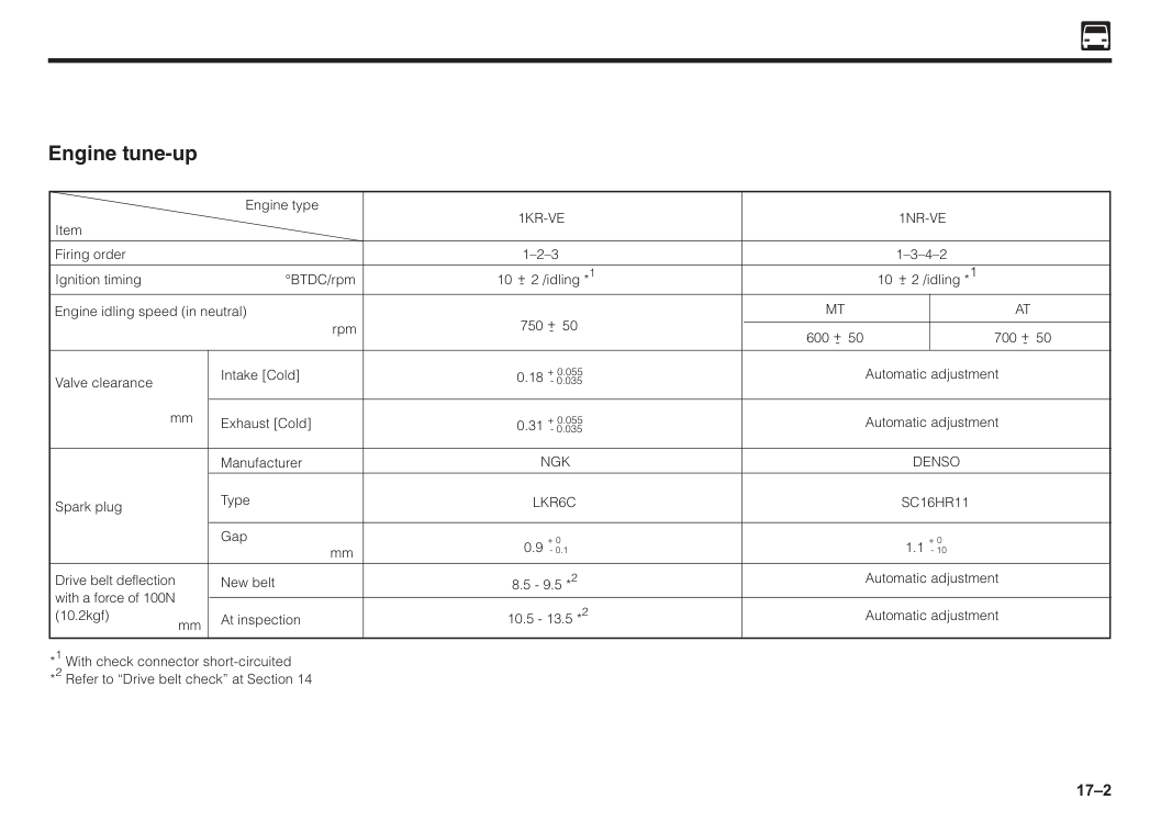
17–2 Engine tune-up 750 50 Firing order Ignition timing °BTDC/rpm Intake [Cold] Exhaust [Cold] Manufacturer New belt At inspection Type Gap mm mm Spark plug Drive belt deflection with a force of 100N (10.2kgf) Item Engine type *1 With check connector short-circuited *2 Refer to “Drive belt check” at Section 14 Valve clearance
mm Engine idling speed (in neutral)
rpm 1–2–3 10 2 /idling *1
Ngk
Lkr6C
+- 600 50 +- 700 50 +- +- 8.5 - 9.5 *2 10.5 - 13.5 *21Kr-Ve
+ 0.055Denso
Sc16Hr11
+-1Nr-Ve
Mt
At
Automatic adjustment Automatic adjustment Automatic adjustment Automatic adjustment 1.1 + 0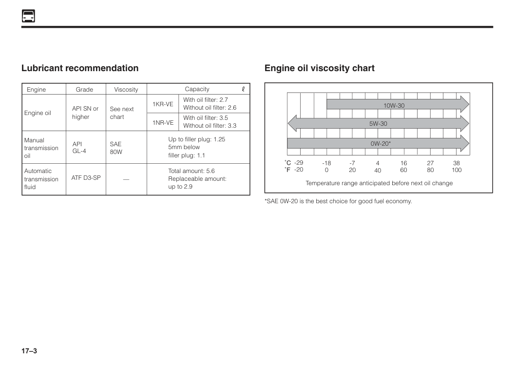
17–3 Lubricant recommendation Grade Engine
Sae
80W
— Viscosity Engine oil API SN or1Kr-Ve
1Nr-Ve
higher See next chart With oil filter: 2.7 Without oil filter: 2.6 With oil filter: 3.5 Without oil filter: 3.3 Up to filler plug: 1.25 5mm below filler plug: 1.1 Total amount: 5.6 Replaceable amount: up to 2.9 Manual transmission oilApi
Gl-4
Automatic transmission fluid CapacityAtf D3-Sp
Engine oil viscosity chart Temperature range anticipated before next oil change -29 -20 -18 0 -7 20 4 40 16 60 27 80 38 1005W-30
10W-30
0W-20*
*SAE 0W-20 is the best choice for good fuel economy.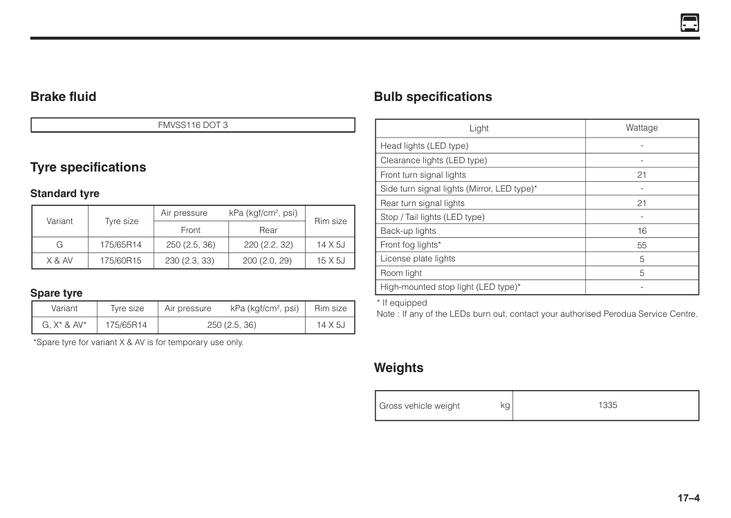
17–4 Brake fluid
Fmvss116 Dot 3
Tyre specifications Standard tyre Air pressure kPa (kgf/cm2, psi) Front Tyre size175/65R14
175/60R15
250 (2.5, 36) 230 (2.3, 33) 220 (2.2, 32) 200 (2.0, 29) VariantG
X & Av
14 X 5J
15 X 5J
Rear Rim size Spare tyre Air pressure kPa (kgf/cm2, psi) Tyre size175/65R14
250 (2.5, 36) VariantG, X* & Av*
14 X 5J
Rim size *Spare tyre for variant X & AV is for temporary use only. Bulb specifications Light Head lights (LED type) Wattage Clearance lights (LED type) Front turn signal lights Side turn signal lights (Mirror, LED type)* 21 Rear turn signal lights 21 16 55 Stop / Tail lights (LED type) License plate lights 5 Front fog lights* Room light 5 High-mounted stop light (LED type)*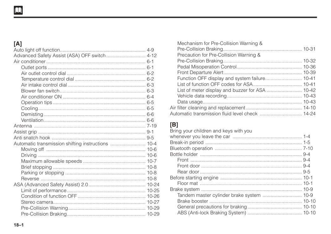
18–1
[A]
Auto light off function................................................................ 4-9 Advanced Safety Assist (ASA) OFF switch.............................. 4-12 Air conditioner.......................................................................... 6-1 Outlet ports......................................................................... 6-1 Air outlet control dial........................................................... 6-2 Temperature control dial..................................................... 6-2 Air intake control dial.......................................................... 6-3 Blower fan switch................................................................ 6-3 Air conditioner ON.............................................................. 6-4 Operation tips..................................................................... 6-5 Cooling................................................................................ 6-5 Demisting............................................................................ 6-6 Ventilation............................................................................ 6-6 Antenna ................................................................................... 7-19 Assist grip ................................................................................ 9-1 Anti snatch hook ...................................................................... 9-5 Automatic transmission shifting instructions ........................... 10-4 Moving off .......................................................................... 10-6 Driving ................................................................................ 10-6 Maximum allowable speeds............................................... 10-7 Brief stopping .................................................................... 10-8 Parking or stopping ........................................................... 10-8 Reverse .............................................................................. 10-8 ASA (Advanced Safety Assist) 2.0........................................... 10-24 Limit of performance........................................................... 10-25 Condition of function OFF................................................... 10-26 Stereo camera..................................................................... 10-27 Pre-Collision Warning.......................................................... 10-29 Pre-Collision Braking........................................................... 10-29 Mechanism for Pre-Collision Warning & Pre-Collision Braking........................................................... 10-31 Precaution for Pre-Collision Warning & Pre-Collision Braking........................................................... 10-32 Pedal Misoperation Control................................................. 10-36 Front Departure Alert.......................................................... 10-39 Function OFF display and system failure............................ 10-41 List of function OFF codes for ASA..................................... 10-41 List of meter display and buzzer for ASA........................... 10-42 Vehicle data recording........................................................ 10-43 Data usage......................................................................... 10-43 Air filter cleaning and replacement.......................................... 14-10 Automatic transmission fluid level check ................................ 14-24[B]
Bring your children and keys with you whenever you leave the car .................................................... 1-4 Break-in period ........................................................................ 1-5 Bluetooth operation ................................................................. 7-10 Bottle holder ............................................................................ 9-4 Front ................................................................................... 9-4 Front door ........................................................................... 9-4 Rear door............................................................................ 9-5 Before starting engine ............................................................. 10-1 Floor mat ............................................................................ 10-1 Brake system ........................................................................... 10-9 Tandem master cylinder brake system .............................. 10-9 Brake booster .................................................................... 10-10 General precautions for braking......................................... 10-10 ABS (Anti-lock Braking System) ........................................ 10-10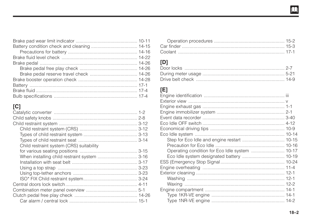
18–2 Brake pad wear limit indicator ................................................. 10-11 Battery condition check and cleaning .................................... 14-15 Precautions for battery ....................................................... 14-16 Brake fluid level check ............................................................ 14-22 Brake pedal ............................................................................. 14-26 Brake pedal free play check .............................................. 14-26 Brake pedal reserve travel check ...................................... 14-26 Brake booster operation check ............................................... 14-28 Battery ..................................................................................... 17-1 Brake fluid................................................................................ 17-4 Bulb specifications .................................................................. 17-4
[C]
Catalytic converter .................................................................. 1-2 Child safety knobs ................................................................... 2-8 Child restraint system .............................................................. 3-12 Child restraint system (CRS) .............................................. 3-12 Types of child restraint system .......................................... 3-13 Types of child restraint seat ............................................... 3-14 Child restraint system (CRS) suitability for various seating positions .............................................. 3-15 When installing child restraint system ................................ 3-16 Installation with seat belt .................................................... 3-17 Using a top strap ............................................................... 3-23 Using top-tether anchors ................................................... 3-23 ISO* FIX Child restraint system........................................... 3-24 Central doors lock switch......................................................... 4-11 Combination meter panel overview ......................................... 5-1 Clutch pedal free play check .................................................. 14-26 Car alarm / central lock ...................................................... 15-1 Operation procedures ........................................................ 15-2 Car finder ................................................................................. 15-3 Coolant .................................................................................... 17-1[D]
Door locks ............................................................................... 2-7 During meter usage ................................................................. 5-21 Drive belt check ...................................................................... 14-9[E]
Engine identification ................................................................ iii Exterior view ............................................................................ v Engine exhaust gas ................................................................. 1-1 Engine immobilizer system ...................................................... 2-1 Event data recorder ................................................................. 3-40 Eco Idle OFF switch................................................................. 4-12 Economical driving tips ........................................................... 10-9 Eco Idle system ....................................................................... 10-14 Step for Eco Idle and engine restart .................................. 10-15 Precaution for Eco Idle ....................................................... 10-16 Operating condition for Eco Idle system ........................... 10-17 Eco Idle system designated battery .................................. 10-19 ESS (Emergency Stop Signal................................................... 10-24 Engine overheating ................................................................. 11-4 Exterior cleaning ...................................................................... 12-1 Washing ............................................................................. 12-1 Waxing ............................................................................... 12-2 Engine compartment ............................................................... 14-1 Type 1KR-VE engine .......................................................... 14-1 Type 1NR-VE engine .......................................................... 14-2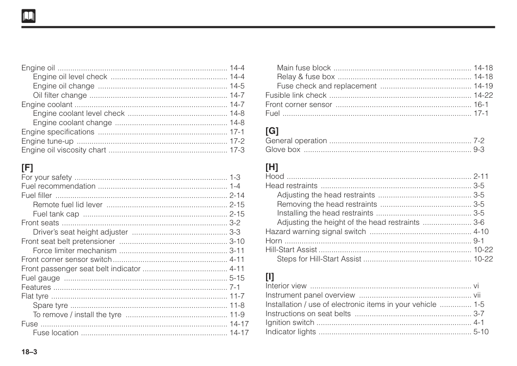
18–3 Engine oil ................................................................................. 14-4 Engine oil level check ........................................................ 14-4 Engine oil change .............................................................. 14-5 Oil filter change .................................................................. 14-7 Engine coolant ......................................................................... 14-7 Engine coolant level check ................................................ 14-8 Engine coolant change ...................................................... 14-8 Engine specifications .............................................................. 17-1 Engine tune-up ........................................................................ 17-2 Engine oil viscosity chart ......................................................... 17-3
[F]
For your safety ......................................................................... 1-3 Fuel recommendation .............................................................. 1-4 Fuel filler .................................................................................. 2-14 Remote fuel lid lever .......................................................... 2-15 Fuel tank cap ..................................................................... 2-15 Front seats ............................................................................... 3-2 Driver’s seat height adjuster .............................................. 3-3 Front seat belt pretensioner .................................................... 3-10 Force limiter mechanism .................................................... 3-11 Front corner sensor switch....................................................... 4-11 Front passenger seat belt indicator......................................... 4-11 Fuel gauge .............................................................................. 5-15 Features ................................................................................... 7-1 Flat tyre .................................................................................... 11-7 Spare tyre ........................................................................... 11-8 To remove / install the tyre ................................................. 11-9 Fuse ......................................................................................... 14-17 Fuse location ...................................................................... 14-17 Main fuse block .................................................................. 14-18 Relay & fuse box ................................................................ 14-18 Fuse check and replacement ............................................ 14-19 Fusible link check .................................................................... 14-22 Front corner sensor ................................................................. 16-1 Fuel .......................................................................................... 17-1[G]
General operation .................................................................... 7-2 Glove box ................................................................................ 9-3[H]
Hood ........................................................................................ 2-11 Head restraints ........................................................................ 3-5 Adjusting the head restraints ............................................. 3-5 Removing the head restraints ............................................ 3-5 Installing the head restraints .............................................. 3-5 Adjusting the height of the head restraints ........................ 3-6 Hazard warning signal switch ................................................. 4-10 Horn ......................................................................................... 9-1 Hill-Start Assist......................................................................... 10-22 Steps for Hill-Start Assist.................................................... 10-22[I]
Interior view ............................................................................. vi Instrument panel overview ...................................................... vii Installation / use of electronic items in your vehicle ................ 1-5 Instructions on seat belts ........................................................ 3-7 Ignition switch .......................................................................... 4-1 Indicator lights ......................................................................... 5-10
18–4 Automatic transmission shift indicator light ....................... 5-10 High beam indicator light .................................................. 5-11 Front fog light-on indicator light.......................................... 5-11 Turn signal indicator light / Hazard warning signal indicator light ........................................................... 5-11 Security indicator light ....................................................... 5-12 Eco indicator light .............................................................. 5-12 Service information reminder indicator .............................. 5-12 VSC OFF indicator light ..................................................... 5-13 TRC OFF indicator light ..................................................... 5-13 Slip indicator light .............................................................. 5-13 Eco Idle ready indicator light ............................................. 5-14 Eco Idle OFF indicator light ............................................... 5-14 ASA operation indicator light.............................................. 5-14 ASA OFF indicator light...................................................... 5-15 Installation ............................................................................... 7-16 Inside mirror ............................................................................ 8-2 Interior lights ............................................................................ 9-1 Room light .......................................................................... 9-1 If engine won’t start ................................................................. 11-1 In case the starter won’t crank ........................................... 11-1 In case the starter cranks .................................................. 11-1 Interior cleaning ....................................................................... 12-2 Instructions on do-it-yourself maintenance service ................. 14-3 Electric engine cooling fan ................................................ 14-4 Introduction ............................................................................. 15-1 Keyless entry / transmitter ................................................. 15-1 Important ................................................................................. 15-3
[J]
Jump-starting .......................................................................... 11-2[K]
Keys (with engine immobilizer system) ................................... 2-1 Key reminder buzzer ............................................................... 4-7[L]
Light bulb replacement ........................................................... 14-30 Headlights .......................................................................... 14-30 Clearance lights / front turn signal lights ........................... 14-31 Front fog lights ................................................................... 14-32 Side turn signal lights (mirror) ............................................ 14-33 Rear combination lights ..................................................... 14-34 Licence plate lights ............................................................ 14-35 Luggage lights ................................................................... 14-36 Room lights ........................................................................ 14-37 Lubricant recommendation ..................................................... 17-3[M]
Modification of your vehicle ..................................................... 1-4 Multi-control switch .................................................................. 4-7 Head light control ............................................................... 4-7 Turn signal light control ...................................................... 4-8 Fog light switch................................................................... 4-8 Multi information display ......................................................... 5-16 Average fuel consumption (AVG) ...................................... 5-17 Curent fuel concumption (CFC) mode ............................... 5-17 Distance to empty (RANGE) .............................................. 5-18 Eco Idle stop time .............................................................. 5-18
18–5 Eco Idle stop cumulative time ............................................ 5-19 Service information reminder setting ................................. 5-19 Eco indicator light display setting ...................................... 5-20 Eco Idle display setting ..................................................... 5-20 Mobile phone compartment .................................................... 9-4 Manual transmission shifting instructions ................................ 10-2 Maintenance requirements ...................................................... 13-1 Maintenance schedule ............................................................ 13-3 Schedule for NORMAL driving .......................................... 13-3 Schedule for SEVERE driving ............................................ 13-7 Recommended periodical maintenance guide for air conditioner................................................................ 13-8 Manual transmission oil level check ........................................ 14-24
[N]
Normal driving tips .................................................................. 10-9[O]
Odometer and trip meter ......................................................... 5-16[P]
Power windows ........................................................................ 2-9 Power window lock switch ................................................. 2-9 Master switch ..................................................................... 2-10 Window switch ................................................................... 2-10 Window Jam Pro ................................................................ 2-11 Power socket ........................................................................... 4-13 Playing USB ............................................................................. 7-7 Push start system .................................................................... 4-2 Engine start/stop button ..................................................... 4-3 To start engine ................................................................... 4-3 To switch engine switch mode ........................................... 4-3 To stop engine ................................................................... 4-4 Steering lock ...................................................................... 4-4 Precaution for engine switch .............................................. 4-5 Parking tips .............................................................................. 10-12 Parking brake ..................................................................... 10-12 Parking on slope ................................................................ 10-13 Parking brake warning buzzer ................................................ 10-14 Power steering ......................................................................... 10-14 Parking brake reserve travel check ......................................... 14-27 Panic button ............................................................................ 15-3[Q]
[R]
Remote keyless entry/transmitter ............................................ 2-5 Rear seats ............................................................................... 3-4 Before folding the seatback ............................................... 3-4 Folding the seatback ......................................................... 3-4 Rear window defogger switch ................................................. 4-10 Rear USB phone charging....................................................... 4-13 Radio wire connection ............................................................. 7-17 Rust prevention ....................................................................... 12-3 Replacement of battery in the transmitter ............................... 15-4 Type 1................................................................................. 15-4 Type 2................................................................................. 15-5 Reverse sensor ........................................................................ 16-1
18–6
[S]
Smart entry .............................................................................. 2-2 Smart door lock and unlock................................................ 2-2 Emergency key................................................................... 2-5 Seats ........................................................................................ 3-1 Correct driving posture....................................................... 3-1 Seat belt warning light and buzzer.......................................... 3-10 SRS (Supplemental Restraint System) air bags for driver and front passenger ...................................................... 3-26 SRS air bag ............................................................................. 3-30 How air bag operates......................................................... 3-31 Cases where the air bags are actuated.............................. 3-32 Cases where the air bags are not actuated........................ 3-33 Important safety warning ................................................... 3-36 Service instructions ............................................................ 3-38 Air bag computer ............................................................... 3-39 Stereo camera.......................................................................... 4-14 Speedometer............................................................................ 5-21 Specification ............................................................................ 7-18 Side mirrors ............................................................................. 8-1 Sun visor .................................................................................. 9-2 Vanity mirror ....................................................................... 9-2 Ticket holder ...................................................................... 9-2 SRS airbag warning label .................................................. 9-2 Shopping hook ........................................................................ 9-5 Seatback pocket ..................................................................... 9-6 Starting engine ........................................................................ 10-1 Starting procedure ............................................................. 10-2 Precautions for automatic transmission- equipped vehicle ............................................................... 10-2 Shifting points (Manual transmission) ..................................... 10-3 Recommended shifting speeds ......................................... 10-3 Maximum allowable speeds .............................................. 10-3 Spark plug check and replacement ........................................ 14-11 Type 1................................................................................. 14-11 Type 2................................................................................. 14-13 Steering wheel free play check ............................................... 14-25[T]
Trunk/boot ................................................................................ 2-13 Tachometer .............................................................................. 5-21 Tuner Operation ....................................................................... 7-5 Tools ........................................................................................ 11-5 Jack ................................................................................... 11-5 Tool bag ............................................................................. 11-6 Towing ..................................................................................... 11-14 Flat bed type ...................................................................... 11-14 Wheel lift type .................................................................... 11-14 Emergency towing ............................................................. 11-15 Towing hook ....................................................................... 11-16 Instructions on towing ........................................................ 11-16 Other vehicle towing .......................................................... 11-17 Tyres ........................................................................................ 14-37 Tyre air pressure ................................................................ 14-37 Tyre rotation ....................................................................... 14-38 Tyre wear check ................................................................. 14-38 Instructions on tyres ........................................................... 14-39 Tyre specifications ................................................................... 17-4
18–7
[U]
Utility box ................................................................................. 9-3 Center panel ...................................................................... 9-3 Driver’s side ....................................................................... 9-3[V]
Vehicle identification ................................................................ ii Vehicle data recordings........................................................... 3-40 VSC & TRC OFF switch............................................................ 4-12 VSC (Vehicle stability control) . TRC (Traction control)............ 10-20 VSC .................................................................................... 10-20 TRC .................................................................................... 10-20 Vehicle specifications............................................................... 17-1[W]
Warning buzzer ....................................................................... 2-5 Wiper and washer switches .................................................... 4-9 Windshield wiper and washer switch ................................ 4-10 Warning lights .......................................................................... 5-2 Parking brake warning light ............................................... 5-2 Brake warning light ............................................................ 5-3 Oil pressure warning light .................................................. 5-4 Battery charge warning light .............................................. 5-4 Malfunction indicator light (MIL) ........................................ 5-5 ABS (Anti-lock Braking System) warning light ................... 5-5 Automatic transmission warning light ................................ 5-6 Seat belt warning light ....................................................... 5-6 Air bag warning light .......................................................... 5-7 Door ajar warning light ....................................................... 5-7 Low fuel level warning light ................................................ 5-8 Water temperature warning light ........................................ 5-8 Power steering warning light ............................................. 5-8 Key-free warning light ....................................................... 5-9 Master warning light................................................................. 5-9 Advanced Safety Assist (ASA) error warning light................... 5-10 Advanced Safety Assist (ASA) OFF warning light................... 5-10 Warning sounds....................................................................... 11-17 Windshield washer fluid level check ....................................... 14-23 Wiper blade replacement ........................................................ 14-28 Front ................................................................................... 14-28 Weights .................................................................................... 17-4[X]
[Y]
Your Owner’s Manual ............................................................... i Your responsibility for maintenance ........................................ ii[Z]
[3] 3-point emergency lock retractor type seat belts (ELR) ......... 3-9
The following Wireless Communication products in this vehicle is certified (Type Approved) by SIRIM under Communication and Multimedia Act 1998 Keyless entry systems (keyless transmitter), Keyless entry systems/immobilizer (smartkey transmitter), Immobilizer equipment (body ECU)
Hidf16000019
Immobilizer systemsHidf15000053
Certification model : TWB1G0125 / TWB1G0126 Frequency band ; 433.92MHz Maximum output power ; 80dBuV/m@3m Manufacturer name : ALPS ELECTRIC CO.,LTD. Manufacturer address : 6-3-36, Furukawanakazato, Osaki City, Miyagi
Prefecture 989-6181, Japan CAUTION - Danger of explosion if battery is incorrectly replaced. Replace only with the same or equivalent type. CAUTION - Do not exposed to excessive heat such as sunshine, fire or the like. CAUTION - Do not give mechanically crushing or cutting of a battery. CAUTION - Do not subjected to extremely low air pressure at high altitude. This symbol is intended to alert the user to the presence of important operating and maintenance (servicing) instructions in the literature accompanying the appliance. Certification model : TWB1G0125 Hereby, ALPS ELECTRIC CO.,LTD., declares that the radio equipment type TWB1G0125 is in compliance with Directive 2014/53/EU. The full text of the EU declaration of confirmity is available at the following internet address : https://www.alps.com/products/common/pdf/HandUnit/TWB1G0125.pdf Certification model : TWB1G0126 Hereby, ALPS ELECTRIC CO.,LTD., declares that the radio equipment type TWB1G0126 is in compliance with Directive 2014/53/EU. The full text of the EU declaration of confirmity is available at the following internet address : https://www.alps.com/products/common/pdf/HandUnit/TWB1G0084.pdf
For vehicles sold in Fiji Certification model : TWB1G0125/TWB1G0126/DA5501 This device complies with part 15 of the FCC Rules. Operation is subject to the following two conditions : (1) This device may not cause harmful interference, and (2) this device must accept any interference received, including interference that may cause undesired operation.
Fcc Caution
Changes or modifications not expressly approved by the party responsible for compliance could void the user's authority to operate the equipment.Warning
Do not ingest the battery, Chemical Burn Hazard (The remote control supplied with) This product contains a coin/button cell battery. If the coin/button cell battery is swallowed, it can cause severe internal burns in just 2 hours and can lead to death. Keep new and used batteries away from children. If the battery compartment does not close securely, stop using the product and keep it away from children. If you think batteries might have been swallowed or placed inside any part of the body, seek immediate medical attention. Certification model : TWB1G0125 Certification model : TWB1G0126
For vehicles sold in Singapore Certification model : TWB1G0125/TWB1G0126/DA5501/EMU36090 Complies with IMDA Standards
Da107248
Certification model : DA5501 Frequency band : 125kHz Maximum output power : 16.6dBuA/m@10m Manufacturer name : Sumitomo Wiring Systems, Ltd. Manufacturer address : 1820 Nakanoike, Mikkaichi-cho, Suzuka, Mie 513-8631 Japan Hereby, Sumitomo Wiring Systems, Ltd. declares that the radio equipment type DA5501 is in compliance with Directive 2014/53/EU. The full text of the EU declaration of confirmity is available at the following internet address : https://www.sws.co.jp/en/product/document/certificate/pdf/red_doc_for_da5501.pdf Le soussigne', Sumitomo Wiring Systems, Ltd., declare que I'equipment radioelectrique du type DA5501 est conforme a la directive 2014/53/EU. Le texte complet de la declaration UE de conformite est disponible a I'adresse internet suivante : https://www.sws.co.jp/en/product/document/certificate/pdf/red_doc_for_da5501.pdf Certification model : DA5502 Manufacturer name : Sumitomo Wiring Systems, Ltd. Manufacturer address : 1820 Nakanoine, Mikkaichi-cho, Suzuka, Mie 513-8631 Japan Hereby, Sumitomo Wiring Systems, Ltd. declares that the radio equipment type DA5502 is in compliance with Directive 2014/53/UE. The full text of the EU declaration of confirmity is available at the following internet address : https://www.sws.co.jp/en/product/document/certificate/pdf/red_doc_for_da5502.pdf Le soussigne', Sumitomo Wiring Systems, Ltd., declare que I'equipment radioelectrique du type DA5502 est conforme a la directive 2014/53/EU. Le texte complet de la declaration UE de conformite est disponible a I'adresse internet suivante : https://www.sws.co.jp/en/product/document/certificate/pdf/red_doc_for_da5502.pdf
For vehicles sold in Seychelles Certification model : DA5501/DA5502 Importer name : SF Hybrid Motors Importer trademark : SF Hybrid Motors Importer address : Industrial Estate Providence Mahe, Seychelles Certification model : TWB1G0125/TWB1G0126 This device complies with part 15 of the FCC Rules. Operation is subject to the following two conditions : (1) This device may not cause harmful interference, and (2) this device must accept any interference received, including interference that may cause undesired operation.
Fcc Caution
Changes or modifications not expressly approved by the party responsible for compliance could void the user's authority to operate the equipment.