
Ask AI
— answers from the official manualAnswers from the official manual.
Common questions
Common Questions
10 totalHow do I set up and start the air compressor for the first time?
For initial setup, ensure all nuts and bolts are tightened, remove the white plug and replace it with a red bung, screw in the air filter, place the compressor in a clean, dry, and ventilated area. Check voltage is within ±4% of the rated value. Then connect to power supply with the switch knob set to off and allow the motor to cycle for 10 minutes without load to ensure lubrication.
What safety measures should I take when operating the air compressor?
Always wear eye protection such as goggles, use hearing protection like ear plugs or ear defenders, do not touch any moving parts, and operate in a clean and dry environment. Ensure proper safety attire is worn to avoid entanglement with loose clothing or jewelry.
How often should I maintain the air compressor's oil levels?
Check and replenish the oil level through the sightglass before each use, ensuring it stays within the red circle. After the first 10 working hours and every 120 working hours thereafter, change the oil completely by draining all old oil and replacing with fresh oil.
How do I adjust the output pressure of compressed air?
The output pressure can be adjusted using the regulating valve's knob. Grip it and turn clockwise to increase, and anticlockwise to decrease the desired outlet pressure.
What should I do after every use of the air compressor?
After each use, vent the compressor by turning the regulator knob fully anticlockwise. Then remove any condensation from inside the tank by unscrewing the bleed nipple.
What are some common maintenance tasks for this air compressor?
Regularly check the safety valve and pressure gauge every six months at a certified repair center. Ensure no rust on the air tank and check its thickness annually to ensure it is not less than 2.1mm.
Full Manual
11 pages
|SC24H AIR COMPRESSOR|SC24H AIR COMPRESSOR| |---|---| |OWNER’S MANUAL|OWNER’S MANUAL| ||| |FOR YOUR SAFETY PLEASE READ THESE INSTRUCTIONS CAREFULLY AND RETAIN THEM FOR FUTURE USE.|


|
|MAIN COMPONENTS
|1. Main compressor
2. Pressure switch
3. Outlet Valve
4. Regulating Valve
5. Pressure gauge
6. One-way Valve
7. Drain cock
8. Wheels
9. Discharge pipe
10. Air tank resevoir
11. Safety valve
12. Fan cover
12.1. 2.

3.
4.
5.
6.
7.
8.
9.
10.
11.
| |---|
SPECIFICATION
LIST OF GOODS
||ITEM|LIST OF GOODS|QTY| |---|---|---| |1|Air Compressor|1| |2|Air Filter|1| |3|Breather Pipe|1| |4|Wheel|2| |5|Wheel Axis|2| |6|Rubber Gasket|1 or 2| |7|Instruction Manual|1| | |---|
|ITEM|DATA|DATA| |---|---|---| |Model|SC24H|SC50H| |Power|1.5 kW / 2.5 HP|1.5 kW / 2.5 HP| |Voltage|230 V|230 V| |Frequency|50 Hz|50 Hz| |Motor Poles|2 P|2 P| |Rated Speed|2850 rpm|2850 rpm| |Current|7.5 A|7.5 A| |Delivery|9.6 CFM|9.6 CFM| |Discharge Pressure|115 PSI / 0.8 MPa|115 PSI / 0.8 MPa|
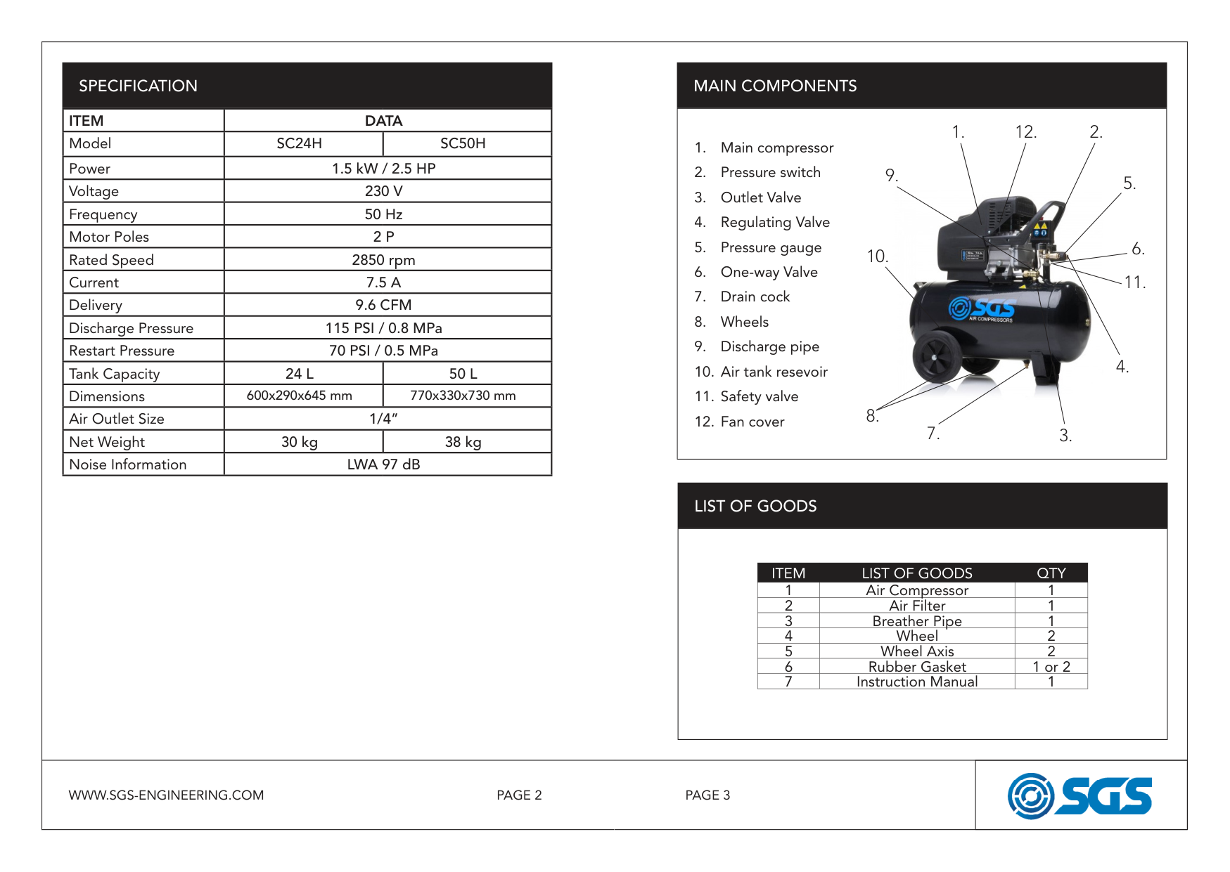
|Restart Pressure|70 PSI / 0.5 MPa|70 PSI / 0.5 MPa| |Tank Capacity|24 L|50 L| |Dimensions|600x290x645 mm|770x330x730 mm| |Air Outlet Size|1/4”|1/4”| |Net Weight|30 kg|38 kg| |Noise Information|LWA 97 dB|LWA 97 dB| |MAIN COMPONENTS
|1. Main compressor
2. Pressure switch
3. Outlet Valve
4. Regulating Valve
5. Pressure gauge
6. One-way Valve
7. Drain cock
8. Wheels
9. Discharge pipe
10. Air tank resevoir
11. Safety valve
12. Fan cover
12.1. 2.

3.
4.
5.
6.
7.
8.
9.
10.
11.
| |---|
SPECIFICATION
LIST OF GOODS
||ITEM|LIST OF GOODS|QTY| |---|---|---| |1|Air Compressor|1| |2|Air Filter|1| |3|Breather Pipe|1| |4|Wheel|2| |5|Wheel Axis|2| |6|Rubber Gasket|1 or 2| |7|Instruction Manual|1| | |---|
|ITEM|DATA|DATA| |---|---|---| |Model|SC24H|SC50H| |Power|1.5 kW / 2.5 HP|1.5 kW / 2.5 HP| |Voltage|230 V|230 V| |Frequency|50 Hz|50 Hz| |Motor Poles|2 P|2 P| |Rated Speed|2850 rpm|2850 rpm| |Current|7.5 A|7.5 A| |Delivery|9.6 CFM|9.6 CFM| |Discharge Pressure|115 PSI / 0.8 MPa|115 PSI / 0.8 MPa| |Restart Pressure|70 PSI / 0.5 MPa|70 PSI / 0.5 MPa|
|Tank Capacity|24 L|50 L| |Dimensions|600x290x645 mm|770x330x730 mm| |Air Outlet Size|1/4”|1/4”| |Net Weight|30 kg|38 kg| |Noise Information|LWA 97 dB|LWA 97 dB| | |---|---| |PAGE 3PAGE 2WWW.SGS-ENGINEERING.COM|


|
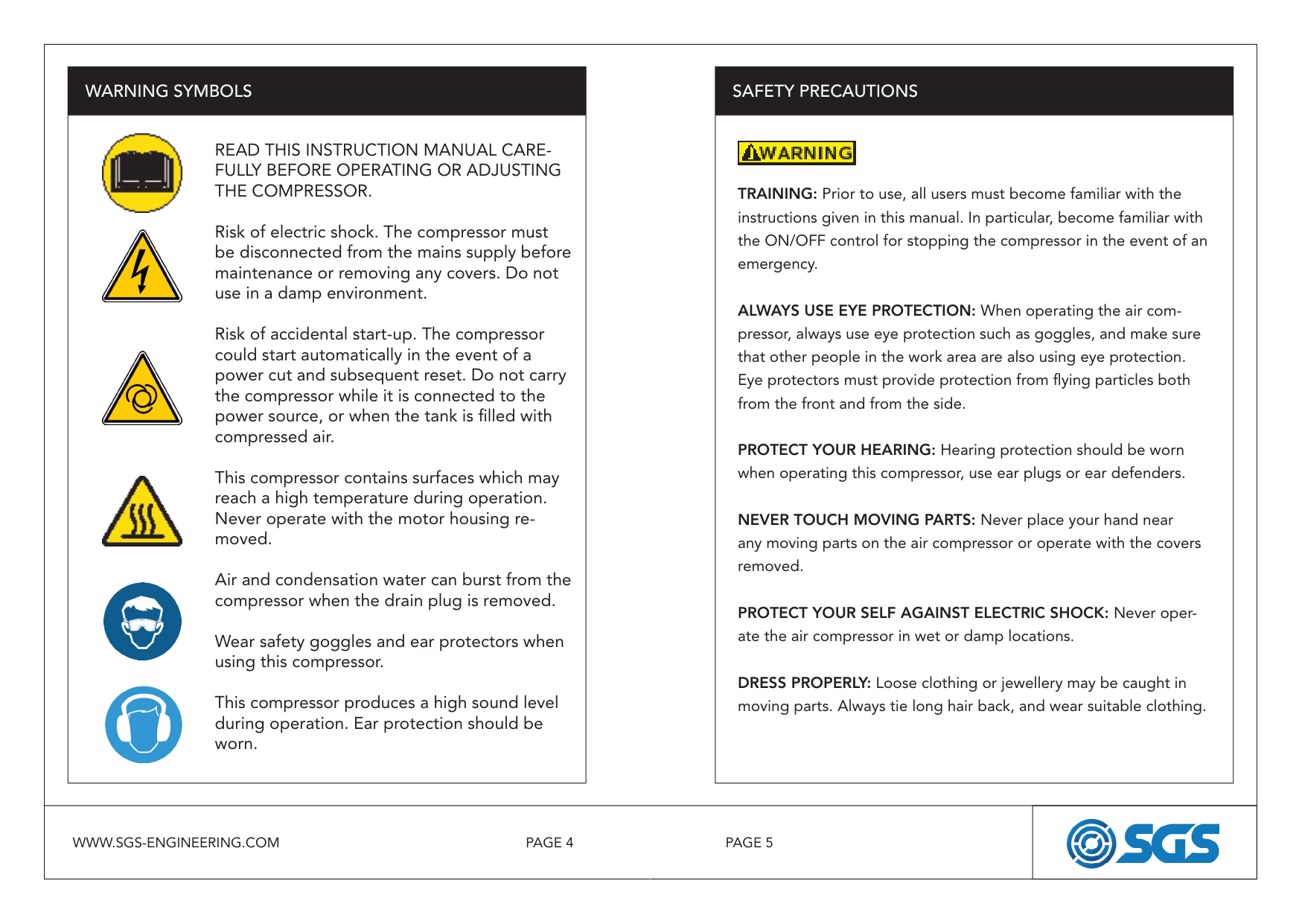
||TRAINING: Prior to use, all users must become familiar with the instructions given in this manual. In particular, become familiar with the ON/OFF control for stopping the compressor in the event of an emergency.
ALWAYS USE EYE PROTECTION: When operating the air compressor, always use eye protection such as goggles, and make sure that other people in the work area are also using eye protection. Eye protectors must provide protection from flying particles both from the front and from the side.
PROTECT YOUR HEARING: Hearing protection should be worn when operating this compressor, use ear plugs or ear defenders.
NEVER TOUCH MOVING PARTS: Never place your hand near any moving parts on the air compressor or operate with the covers removed.
PROTECT YOUR SELF AGAINST ELECTRIC SHOCK: Never operate the air compressor in wet or damp locations.
DRESS PROPERLY: Loose clothing or jewellery may be caught in moving parts. Always tie long hair back, and wear suitable clothing.
| |---|
SAFETY PRECAUTIONSWARNING SYMBOLS
|READ THIS INSTRUCTION MANUAL CAREFULLY BEFORE OPERATING OR ADJUSTING THE COMPRESSOR.
Risk of electric shock. The compressor must be disconnected from the mains supply before maintenance or removing any covers. Do not use in a damp environment.
Risk of accidental start-up. The compressor could start automatically in the event of a power cut and subsequent reset. Do not carry the compressor while it is connected to the power source, or when the tank is filled with compressed air.
This compressor contains surfaces which may reach a high temperature during operation. Never operate with the motor housing removed.
Air and condensation water can burst from the compressor when the drain plug is removed.
Wear safety goggles and ear protectors when using this compressor.
This compressor produces a high sound level during operation. Ear protection should be worn.


| |---| ||TRAINING: Prior to use, all users must become familiar with the instructions given in this manual. In particular, become familiar with the ON/OFF control for stopping the compressor in the event of an emergency.
ALWAYS USE EYE PROTECTION: When operating the air compressor, always use eye protection such as goggles, and make sure that other people in the work area are also using eye protection. Eye protectors must provide protection from flying particles both from the front and from the side.
PROTECT YOUR HEARING: Hearing protection should be worn when operating this compressor, use ear plugs or ear defenders.
NEVER TOUCH MOVING PARTS: Never place your hand near any moving parts on the air compressor or operate with the covers removed.
PROTECT YOUR SELF AGAINST ELECTRIC SHOCK: Never operate the air compressor in wet or damp locations.
DRESS PROPERLY: Loose clothing or jewellery may be caught in moving parts. Always tie long hair back, and wear suitable clothing.
| |---|
SAFETY PRECAUTIONSWARNING SYMBOLS
|READ THIS INSTRUCTION MANUAL CAREFULLY BEFORE OPERATING OR ADJUSTING THE COMPRESSOR.
Risk of electric shock. The compressor must be disconnected from the mains supply before maintenance or removing any covers. Do not use in a damp environment.
Risk of accidental start-up. The compressor could start automatically in the event of a power cut and subsequent reset. Do not carry the compressor while it is connected to the power source, or when the tank is filled with compressed air.
This compressor contains surfaces which may reach a high temperature during operation. Never operate with the motor housing removed.
Air and condensation water can burst from the compressor when the drain plug is removed.
Wear safety goggles and ear protectors when using this compressor.
This compressor produces a high sound level during operation. Ear protection should be worn.


| |---| | |---|---| |PAGE 5PAGE 4WWW.SGS-ENGINEERING.COM|


|
||DISCONNECT THE AIR COMPRESSOR: Always disconnect the air compressor from the mains power supply and decompress before performing maintenance, changing any parts and when not in use.
MAINS POWER CABLE PRECAUTIONS: Never pull on the cable when removing the plug from the mains socket, or lift the compressor by the mains cable.
AVOID UNINTENTIONAL STARTING: When connecting the air compressor to the mains supply make sure the red button on top of the air compressor is in the OFF (down) position.
STORE THE AIR COMPRESSOR PROPERLY: When not in use the air compressor should be stored in a secure, dry place out of the reach of children. Always lock up the storage area.
MAINTAIN THE AIR COMPRESSOR WITH CARE: If the air compressor is damaged in any way, have it repaired by a qualified engineer.
DO NOT USE EXTENSION LEADS: Using extension leads can cause your compressor motor to burn out. Only use extension hoses.
DO NOT WELD TO THE PRESSURE VESSEL Do not weld or modify the pressure vessel in any manner.| |---|
SAFETY PRECAUTIONS
|KEEP VISITORS/CHILDREN AWAY: Do not allow visitors/children to handle the air compressor or attachments and ensure that any people in the work area are suitably dressed.
KEEP THE WORK AREA CLEAN: Cluttered areas mean accidents, so clear the work area of all unnecessary tools, debris and furniture.
DO NOT TOUCH HOT SURFACES: During operation, the motor, connections, compressor body, cylinder head and tubes may get hot, do not touch.
DO NOT DIRECT AN AIR STREAM AT THE BODY: Do not direct the air stream at people or animals, as injury may result. Compressed air can cause soft tissue damage and propel dirt and other particles at high speed.
BREATHING AIR: This compressor should not be used to supply breathing quality air. Never use it as breathing apparatus.
STAY ALERT: Watch what you are doing, use common sense, and do not operate the air compressor when you are tired. The air compressor should not be used if you are under the influence of alcohol, drugs or any medication that makes you drowsy.
DISPOSAL INFORMATION The air compressor should be disposed of in a safe an environmentally friendly manner. Contact your local Council for disposal assistance.| |---|
SAFETY PRECAUTIONS||DISCONNECT THE AIR COMPRESSOR: Always disconnect the air compressor from the mains power supply and decompress before performing maintenance, changing any parts and when not in use.
MAINS POWER CABLE PRECAUTIONS: Never pull on the cable when removing the plug from the mains socket, or lift the compressor by the mains cable.
AVOID UNINTENTIONAL STARTING: When connecting the air compressor to the mains supply make sure the red button on top of the air compressor is in the OFF (down) position.
STORE THE AIR COMPRESSOR PROPERLY: When not in use the air compressor should be stored in a secure, dry place out of the reach of children. Always lock up the storage area.
MAINTAIN THE AIR COMPRESSOR WITH CARE: If the air compressor is damaged in any way, have it repaired by a qualified engineer.
DO NOT USE EXTENSION LEADS: Using extension leads can cause your compressor motor to burn out. Only use extension hoses.
DO NOT WELD TO THE PRESSURE VESSEL Do not weld or modify the pressure vessel in any manner.| |---|
SAFETY PRECAUTIONS
|KEEP VISITORS/CHILDREN AWAY: Do not allow visitors/children to handle the air compressor or attachments and ensure that any people in the work area are suitably dressed.
KEEP THE WORK AREA CLEAN: Cluttered areas mean accidents, so clear the work area of all unnecessary tools, debris and furniture.
DO NOT TOUCH HOT SURFACES: During operation, the motor, connections, compressor body, cylinder head and tubes may get hot, do not touch.
DO NOT DIRECT AN AIR STREAM AT THE BODY: Do not direct the air stream at people or animals, as injury may result. Compressed air can cause soft tissue damage and propel dirt and other particles at high speed.
BREATHING AIR: This compressor should not be used to supply breathing quality air. Never use it as breathing apparatus.
STAY ALERT: Watch what you are doing, use common sense, and do not operate the air compressor when you are tired. The air compressor should not be used if you are under the influence of alcohol, drugs or any medication that makes you drowsy.
DISPOSAL INFORMATION The air compressor should be disposed of in a safe an environmentally friendly manner. Contact your local Council for disposal assistance.| |---|
SAFETY PRECAUTIONS| |---|---| |PAGE 7PAGE 6WWW.SGS-ENGINEERING.COM|


|
|ASSEMBLY
|
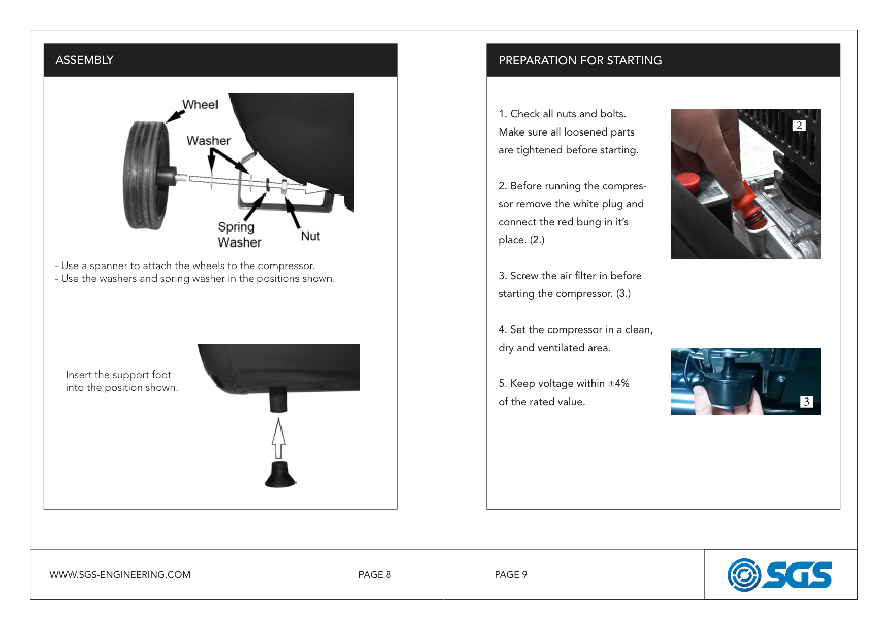
- Use a spanner to attach the wheels to the compressor.
- Use the washers and spring washer in the positions shown.

Insert the support foot into the position shown.| |---|
PREPARATION FOR STARTING
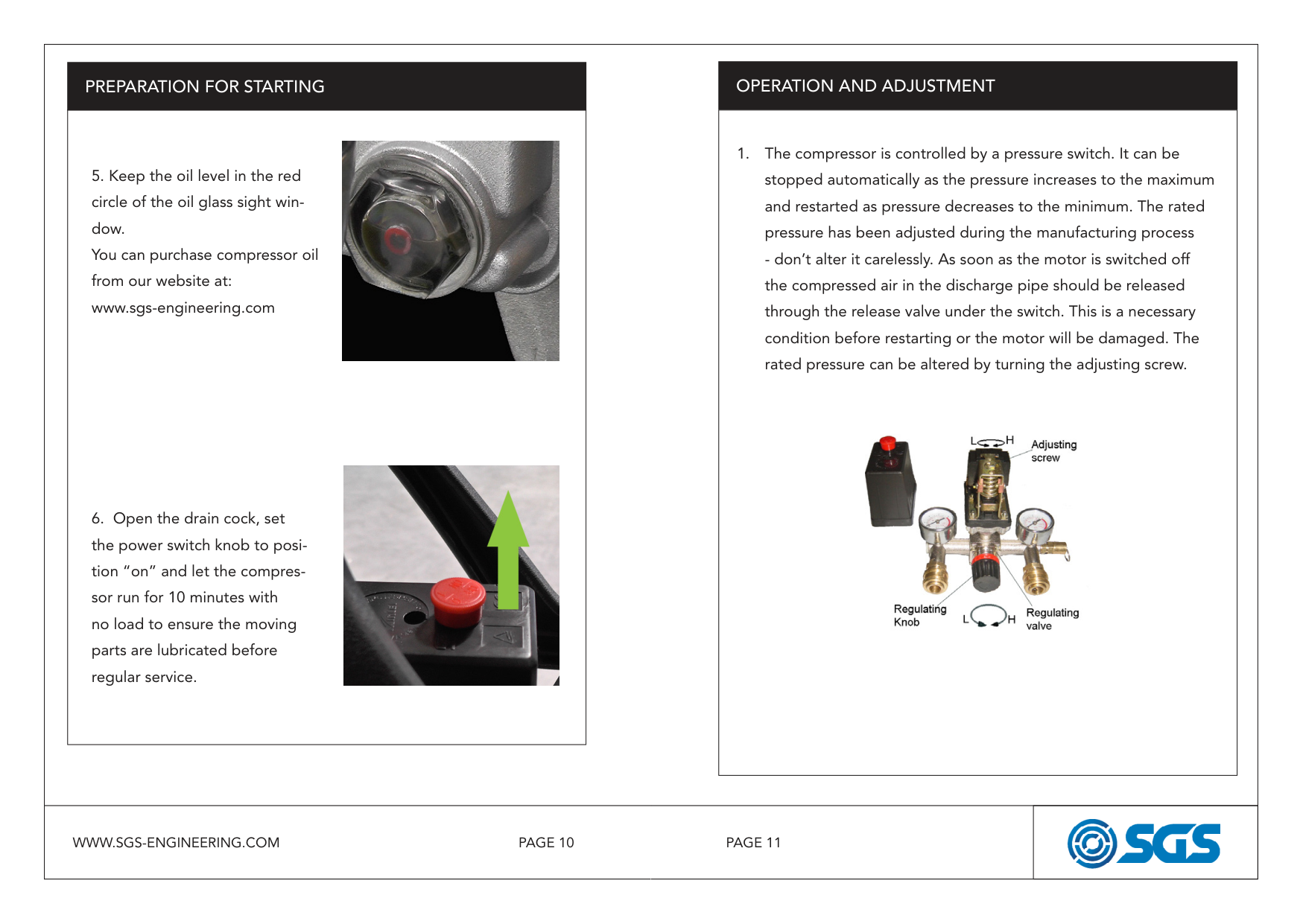
|1. Check all nuts and bolts. Make sure all loosened parts are tightened before starting.
2. Before running the compressor remove the white plug and connect the red bung in it’s place. (2.)
3. Screw the air filter in before starting the compressor. (3.)
4. Set the compressor in a clean, dry and ventilated area.
5. Keep voltage within ±4% of the rated value. 3


2| |---| |ASSEMBLY
|
- Use a spanner to attach the wheels to the compressor.
- Use the washers and spring washer in the positions shown.

Insert the support foot into the position shown.| |---|
PREPARATION FOR STARTING
|1. Check all nuts and bolts. Make sure all loosened parts are tightened before starting.
2. Before running the compressor remove the white plug and connect the red bung in it’s place. (2.)
3. Screw the air filter in before starting the compressor. (3.)
4. Set the compressor in a clean, dry and ventilated area.
5. Keep voltage within ±4% of the rated value. 3


2| |---| | |---|---| |PAGE 9PAGE 8WWW.SGS-ENGINEERING.COM|


|
|PREPARATION FOR STARTING
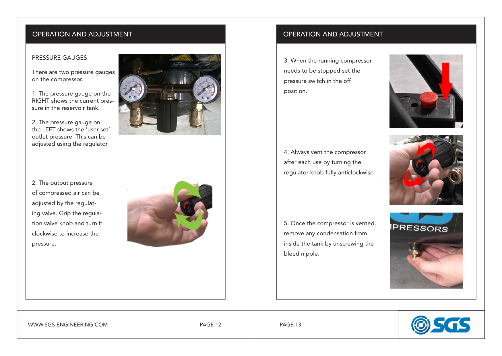
|5. Keep the oil level in the red circle of the oil glass sight window. You can purchase compressor oil from our website at: www.sgs-engineering.com
6. Open the drain cock, set the power switch knob to position “on” and let the compressor run for 10 minutes with no load to ensure the moving parts are lubricated before regular service.

| |---|
|1. The compressor is controlled by a pressure switch. It can be stopped automatically as the pressure increases to the maximum and restarted as pressure decreases to the minimum. The rated pressure has been adjusted during the manufacturing process
- don’t alter it carelessly. As soon as the motor is switched off the compressed air in the discharge pipe should be released through the release valve under the switch. This is a necessary condition before restarting or the motor will be damaged. The rated pressure can be altered by turning the adjusting screw.
| |---|
OPERATION AND ADJUSTMENT|PREPARATION FOR STARTING
|5. Keep the oil level in the red circle of the oil glass sight window. You can purchase compressor oil from our website at: www.sgs-engineering.com
6. Open the drain cock, set the power switch knob to position “on” and let the compressor run for 10 minutes with no load to ensure the moving parts are lubricated before regular service.

| |---|
|1. The compressor is controlled by a pressure switch. It can be stopped automatically as the pressure increases to the maximum and restarted as pressure decreases to the minimum. The rated pressure has been adjusted during the manufacturing process
- don’t alter it carelessly. As soon as the motor is switched off the compressed air in the discharge pipe should be released through the release valve under the switch. This is a necessary condition before restarting or the motor will be damaged. The rated pressure can be altered by turning the adjusting screw.
| |---|
OPERATION AND ADJUSTMENT| |---|---| |PAGE 11PAGE 10WWW.SGS-ENGINEERING.COM|


|
||
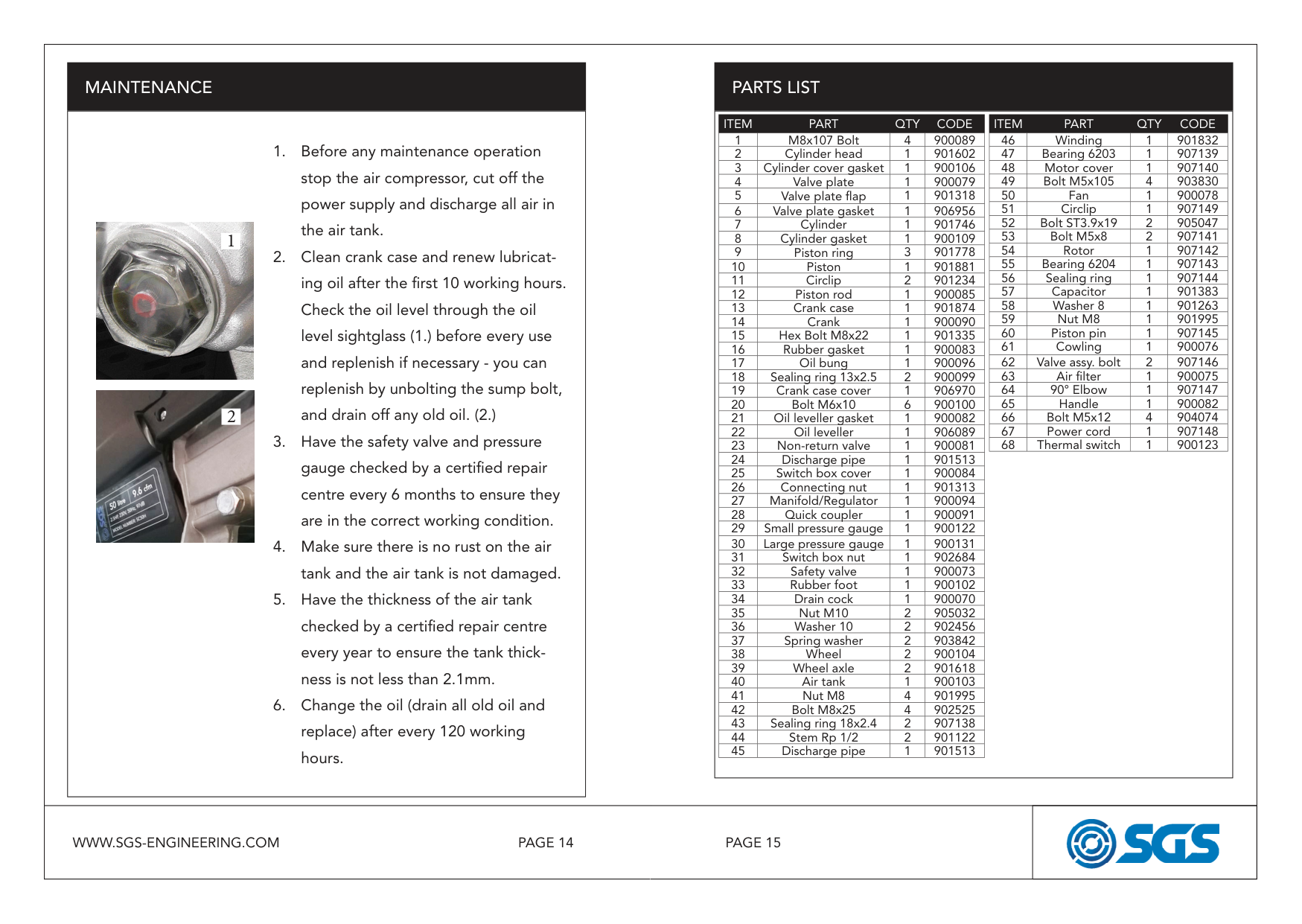
PRESSURE GAUGES There are two pressure gauges on the compressor.
1. The pressure gauge on the RIGHT shows the current pressure in the reservoir tank.
2. The pressure gauge on the LEFT shows the ‘user set’ outlet pressure. This can be adjusted using the regulator.
2. The output pressure of compressed air can be adjusted by the regulating valve. Grip the regulation valve knob and turn it clockwise to increase the pressure.
| |---|
OPERATION AND ADJUSTMENT
|
3. When the running compressor needs to be stopped set the pressure switch in the off position.
4. Always vent the compressor after each use by turning the regulator knob fully anticlockwise.
5. Once the compressor is vented, remove any condensation from inside the tank by unscrewing the bleed nipple.

| |---|
OPERATION AND ADJUSTMENT||
PRESSURE GAUGES There are two pressure gauges on the compressor.
1. The pressure gauge on the RIGHT shows the current pressure in the reservoir tank.
2. The pressure gauge on the LEFT shows the ‘user set’ outlet pressure. This can be adjusted using the regulator.
2. The output pressure of compressed air can be adjusted by the regulating valve. Grip the regulation valve knob and turn it clockwise to increase the pressure.
| |---|
OPERATION AND ADJUSTMENT
|
3. When the running compressor needs to be stopped set the pressure switch in the off position.
4. Always vent the compressor after each use by turning the regulator knob fully anticlockwise.
5. Once the compressor is vented, remove any condensation from inside the tank by unscrewing the bleed nipple.

| |---|
OPERATION AND ADJUSTMENT| |---|---| |PAGE 13PAGE 12WWW.SGS-ENGINEERING.COM|


|
||1. Before any maintenance operation stop the air compressor, cut off the power supply and discharge all air in the air tank.
2. Clean crank case and renew lubricating oil after the first 10 working hours. Check the oil level through the oil level sightglass (1.) before every use and replenish if necessary - you can replenish by unbolting the sump bolt, and drain off any old oil. (2.)
3. Have the safety valve and pressure gauge checked by a certified repair centre every 6 months to ensure they are in the correct working condition.
4. Make sure there is no rust on the air tank and the air tank is not damaged.
5. Have the thickness of the air tank checked by a certified repair centre every year to ensure the tank thickness is not less than 2.1mm.
6. Change the oil (drain all old oil and replace) after every 120 working hours.


2
1| |---|
MAINTENANCE PARTS LIST
||ITEM|PART|QTY|CODE| |---|---|---|---| |1|M8x107 Bolt|4|900089| |2|Cylinder head|1|901602| |3|Cylinder cover gasket|1|900106| |4|Valve plate|1|900079| |5|Valve plate flap|1|901318| |6|Valve plate gasket|1|906956| |7|Cylinder|1|901746| |8|Cylinder gasket|1|900109| |9|Piston ring|3|901778| |10|Piston|1|901881| |11|Circlip|2|901234| |12|Piston rod|1|900085| |13|Crank case|1|901874| |14|Crank|1|900090|
|15|Hex Bolt M8x22|1|901335| |16|Rubber gasket|1|900083| |17|Oil bung|1|900096| |18|Sealing ring 13x2.5|2|900099| |19|Crank case cover|1|906970| |20|Bolt M6x10|6|900100| |21|Oil leveller gasket|1|900082| |22|Oil leveller|1|906089| |23|Non-return valve|1|900081| |24|Discharge pipe|1|901513| |25|Switch box cover|1|900084| |26|Connecting nut|1|901313| |27|Manifold/Regulator|1|900094| |28|Quick coupler|1|900091| |29|Small pressure gauge|1|900122| |30|Large pressure gauge|1|900131| |31|Switch box nut|1|902684| |32|Safety valve|1|900073| |33|Rubber foot|1|900102| |34|Drain cock|1|900070| |35|Nut M10|2|905032| |36|Washer 10|2|902456| |37|Spring washer|2|903842| |38|Wheel|2|900104| |39|Wheel axle|2|901618| |40|Air tank|1|900103| |41|Nut M8|4|901995| |42|Bolt M8x25|4|902525| |43|Sealing ring 18x2.4|2|907138| |44|Stem Rp 1/2|2|901122| |45|Discharge pipe|1|901513|
|ITEM|PART|QTY|CODE| |---|---|---|---| |46|Winding|1|901832| |47|Bearing 6203|1|907139| |48|Motor cover|1|907140| |49|Bolt M5x105|4|903830| |50|Fan|1|900078| |51|Circlip|1|907149| |52|Bolt ST3.9x19|2|905047| |53|Bolt M5x8|2|907141| |54|Rotor|1|907142| |55|Bearing 6204|1|907143| |56|Sealing ring|1|907144| |57|Capacitor|1|901383| |58|Washer 8|1|901263| |59|Nut M8|1|901995| |60|Piston pin|1|907145| |61|Cowling|1|900076| |62|Valve assy. bolt|2|907146| |63|Air filter|1|900075| |64|90° Elbow|1|907147| |65|Handle|1|900082| |66|Bolt M5x12|4|904074| |67|Power cord|1|907148| |68|Thermal switch|1|900123| | |---| ||1. Before any maintenance operation stop the air compressor, cut off the power supply and discharge all air in the air tank.
2. Clean crank case and renew lubricating oil after the first 10 working hours. Check the oil level through the oil level sightglass (1.) before every use and replenish if necessary - you can replenish by unbolting the sump bolt, and drain off any old oil. (2.)
3. Have the safety valve and pressure gauge checked by a certified repair centre every 6 months to ensure they are in the correct working condition.
4. Make sure there is no rust on the air tank and the air tank is not damaged.
5. Have the thickness of the air tank checked by a certified repair centre every year to ensure the tank thickness is not less than 2.1mm.
6. Change the oil (drain all old oil and replace) after every 120 working hours.


2
1| |---|
MAINTENANCE PARTS LIST
||ITEM|PART|QTY|CODE| |---|---|---|---|
|1|M8x107 Bolt|4|900089| |2|Cylinder head|1|901602| |3|Cylinder cover gasket|1|900106| |4|Valve plate|1|900079| |5|Valve plate flap|1|901318| |6|Valve plate gasket|1|906956| |7|Cylinder|1|901746| |8|Cylinder gasket|1|900109| |9|Piston ring|3|901778| |10|Piston|1|901881| |11|Circlip|2|901234| |12|Piston rod|1|900085| |13|Crank case|1|901874| |14|Crank|1|900090| |15|Hex Bolt M8x22|1|901335| |16|Rubber gasket|1|900083| |17|Oil bung|1|900096| |18|Sealing ring 13x2.5|2|900099| |19|Crank case cover|1|906970| |20|Bolt M6x10|6|900100| |21|Oil leveller gasket|1|900082| |22|Oil leveller|1|906089| |23|Non-return valve|1|900081| |24|Discharge pipe|1|901513| |25|Switch box cover|1|900084| |26|Connecting nut|1|901313| |27|Manifold/Regulator|1|900094| |28|Quick coupler|1|900091| |29|Small pressure gauge|1|900122| |30|Large pressure gauge|1|900131| |31|Switch box nut|1|902684|
|32|Safety valve|1|900073| |33|Rubber foot|1|900102| |34|Drain cock|1|900070| |35|Nut M10|2|905032| |36|Washer 10|2|902456| |37|Spring washer|2|903842| |38|Wheel|2|900104| |39|Wheel axle|2|901618| |40|Air tank|1|900103| |41|Nut M8|4|901995| |42|Bolt M8x25|4|902525| |43|Sealing ring 18x2.4|2|907138| |44|Stem Rp 1/2|2|901122| |45|Discharge pipe|1|901513|
|ITEM|PART|QTY|CODE| |---|---|---|---| |46|Winding|1|901832| |47|Bearing 6203|1|907139| |48|Motor cover|1|907140| |49|Bolt M5x105|4|903830| |50|Fan|1|900078| |51|Circlip|1|907149| |52|Bolt ST3.9x19|2|905047| |53|Bolt M5x8|2|907141| |54|Rotor|1|907142| |55|Bearing 6204|1|907143| |56|Sealing ring|1|907144| |57|Capacitor|1|901383| |58|Washer 8|1|901263| |59|Nut M8|1|901995| |60|Piston pin|1|907145|
|61|Cowling|1|900076| |62|Valve assy. bolt|2|907146| |63|Air filter|1|900075| |64|90° Elbow|1|907147| |65|Handle|1|900082| |66|Bolt M5x12|4|904074| |67|Power cord|1|907148| |68|Thermal switch|1|900123| | |---| | |---|---| |PAGE 15PAGE 14WWW.SGS-ENGINEERING.COM|


|
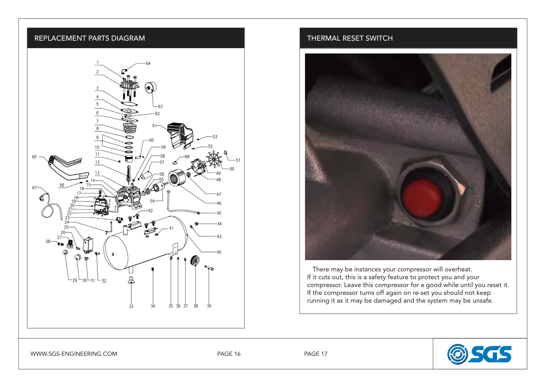
|REPLACEMENT PARTS DIAGRAM
|| |---|
THERMAL RESET SWITCH
|There may be instances your compressor will overheat. If it cuts out, this is a safety feature to protect you and your compressor. Leave this compressor for a good while until you reset it. If the compressor turns off again on re-set you should not keep running it as it may be damaged and the system may be unsafe.
| |---| |REPLACEMENT PARTS DIAGRAM
|| |---|
THERMAL RESET SWITCH
|There may be instances your compressor will overheat. If it cuts out, this is a safety feature to protect you and your compressor. Leave this compressor for a good while until you reset it. If the compressor turns off again on re-set you should not keep running it as it may be damaged and the system may be unsafe.
| |---| | |---|---| |PAGE 17PAGE 16WWW.SGS-ENGINEERING.COM|


|
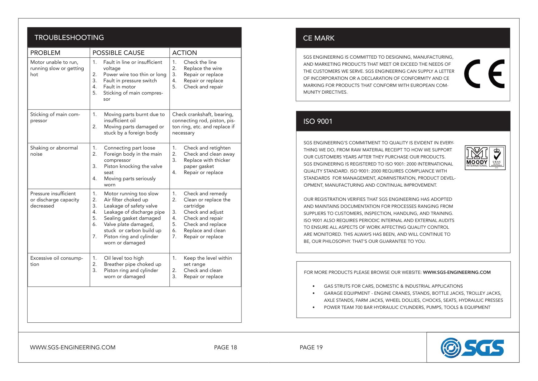
|TROUBLESHOOTING
|PROBLEM|POSSIBLE CAUSE|ACTION| |---|---|---| |Motor unable to run, running slow or getting hot|1. Fault in line or insufficient voltage
2. Power wire too thin or long
3. Fault in pressure switch
4. Fault in motor
5. Sticking of main compressor
|1. Check the line
2. Replace the wire
3. Repair or replace
4. Repair or replace
5. Check and repair
|
|Sticking of main compressor|1. Moving parts burnt due to insufficient oil
2. Moving parts damaged or stuck by a foreign body
|Check crankshaft, bearing, connecting rod, piston, piston ring, etc. and replace if necessary| |Shaking or abnormal noise|1. Connecting part loose
2. Foreign body in the main compressor
3. Piston knocking the valve seat
4. Moving parts seriously worn
|1. Check and retighten
2. Check and clean away
3. Replace with thicker paper gasket
4. Repair or replace
| |Pressure insufficient or discharge capacity decreased|1. Motor running too slow
2. Air filter choked up
3. Leakage of safety valve
4. Leakage of discharge pipe
5. Sealing gasket damaged
6. Valve plate damaged, stuck or carbon build up
7. Piston ring and cylinder worn or damaged
|1. Check and remedy
2. Clean or replace the cartridge
3. Check and adjust
4. Check and repair
5. Check and replace
6. Replace and clean
7. Repair or replace
| |Excessive oil consumption|1. Oil level too high
2. Breather pipe choked up
3. Piston ring and cylinder worn or damaged
|1. Keep the level within set range
2. Check and clean
3. Repair or replace
| | | | |
|
SGS ENGINEERING’S COMMITMENT TO QUALITY IS EVIDENT IN EVERYTHING WE DO, FROM RAW MATERIAL RECEIPT TO HOW WE SUPPORT OUR CUSTOMERS YEARS AFTER THEY PURCHASE OUR PRODUCTS. SGS ENGINEERING IS REGISTERED TO ISO 9001: 2000 INTERNATIONAL QUALITY STANDARD. ISO 9001: 2000 REQUIRES COMPLIANCE WITH STANDARDS FOR MANAGEMENT, ADMINISTRATION, PRODUCT DEVELOPMENT, MANUFACTURING AND CONTINUAL IMPROVEMENT.
OUR REGISTRATION VERIFIES THAT SGS ENGINEERING HAS ADOPTED AND MAINTAINS DOCUMENTATION FOR PROCESSES RANGING FROM SUPPLIERS TO CUSTOMERS, INSPECTION, HANDLING, AND TRAINING. ISO 9001 ALSO REQUIRES PERIODIC INTERNAL AND EXTERNAL AUDITS TO ENSURE ALL ASPECTS OF WORK AFFECTING QUALITY CONTROL ARE MONITORED. THIS ALWAYS HAS BEEN, AND WILL CONTINUE TO BE, OUR PHILOSOPHY. THAT’S OUR GUARANTEE TO YOU.| |---|
|
SGS ENGINEERING IS COMMITTED TO DESIGNING, MANUFACTURING, AND MARKETING PRODUCTS THAT MEET OR EXCEED THE NEEDS OF THE CUSTOMERS WE SERVE. SGS ENGINEERING CAN SUPPLY A LETTER OF INCORPORATION OR A DECLARATION OF CONFORMITY AND CE MARKING FOR PRODUCTS THAT CONFORM WITH EUROPEAN COMMUNITY DIRECTIVES.| |---|
CE MARK
ISO 9001
|FOR MORE PRODUCTS PLEASE BROWSE OUR WEBSITE: WWW.SGS-ENGINEERING.COM
• GAS STRUTS FOR CARS, DOMESTIC & INDUSTRIAL APPLICATIONS
• GARAGE EQUIPMENT - ENGINE CRANES, STANDS, BOTTLE JACKS, TROLLEY JACKS, AXLE STANDS, FARM JACKS, WHEEL DOLLIES, CHOCKS, SEATS, HYDRAULIC PRESSES
• POWER TEAM 700 BAR HYDRAULIC CYLINDERS, PUMPS, TOOLS & EQUIPMENT
| |---| |TROUBLESHOOTING
|PROBLEM|POSSIBLE CAUSE|ACTION| |---|---|---| |Motor unable to run, running slow or getting hot|1. Fault in line or insufficient voltage
2. Power wire too thin or long
3. Fault in pressure switch
4. Fault in motor
5. Sticking of main compressor
|1. Check the line
2. Replace the wire
3. Repair or replace
4. Repair or replace
5. Check and repair
| |Sticking of main compressor|1. Moving parts burnt due to insufficient oil
2. Moving parts damaged or stuck by a foreign body
|Check crankshaft, bearing, connecting rod, piston, piston ring, etc. and replace if necessary| |Shaking or abnormal noise|1. Connecting part loose
2. Foreign body in the main compressor
3. Piston knocking the valve seat
4. Moving parts seriously worn
|1. Check and retighten
2. Check and clean away
3. Replace with thicker paper gasket
4. Repair or replace
| |Pressure insufficient or discharge capacity decreased|1. Motor running too slow
2. Air filter choked up
3. Leakage of safety valve
4. Leakage of discharge pipe
5. Sealing gasket damaged
6. Valve plate damaged, stuck or carbon build up
7. Piston ring and cylinder worn or damaged
|1. Check and remedy
2. Clean or replace the cartridge
3. Check and adjust
4. Check and repair
5. Check and replace
6. Replace and clean
7. Repair or replace
| |Excessive oil consumption|1. Oil level too high
2. Breather pipe choked up
3. Piston ring and cylinder worn or damaged
|1. Keep the level within set range
2. Check and clean
3. Repair or replace
| | | | |
|
SGS ENGINEERING’S COMMITMENT TO QUALITY IS EVIDENT IN EVERYTHING WE DO, FROM RAW MATERIAL RECEIPT TO HOW WE SUPPORT OUR CUSTOMERS YEARS AFTER THEY PURCHASE OUR PRODUCTS. SGS ENGINEERING IS REGISTERED TO ISO 9001: 2000 INTERNATIONAL QUALITY STANDARD. ISO 9001: 2000 REQUIRES COMPLIANCE WITH STANDARDS FOR MANAGEMENT, ADMINISTRATION, PRODUCT DEVELOPMENT, MANUFACTURING AND CONTINUAL IMPROVEMENT.
OUR REGISTRATION VERIFIES THAT SGS ENGINEERING HAS ADOPTED AND MAINTAINS DOCUMENTATION FOR PROCESSES RANGING FROM SUPPLIERS TO CUSTOMERS, INSPECTION, HANDLING, AND TRAINING. ISO 9001 ALSO REQUIRES PERIODIC INTERNAL AND EXTERNAL AUDITS TO ENSURE ALL ASPECTS OF WORK AFFECTING QUALITY CONTROL ARE MONITORED. THIS ALWAYS HAS BEEN, AND WILL CONTINUE TO BE, OUR PHILOSOPHY. THAT’S OUR GUARANTEE TO YOU.| |---|
|
SGS ENGINEERING IS COMMITTED TO DESIGNING, MANUFACTURING, AND MARKETING PRODUCTS THAT MEET OR EXCEED THE NEEDS OF THE CUSTOMERS WE SERVE. SGS ENGINEERING CAN SUPPLY A LETTER OF INCORPORATION OR A DECLARATION OF CONFORMITY AND CE MARKING FOR PRODUCTS THAT CONFORM WITH EUROPEAN COMMUNITY DIRECTIVES.| |---|
CE MARK
ISO 9001
|FOR MORE PRODUCTS PLEASE BROWSE OUR WEBSITE: WWW.SGS-ENGINEERING.COM
• GAS STRUTS FOR CARS, DOMESTIC & INDUSTRIAL APPLICATIONS
• GARAGE EQUIPMENT - ENGINE CRANES, STANDS, BOTTLE JACKS, TROLLEY JACKS, AXLE STANDS, FARM JACKS, WHEEL DOLLIES, CHOCKS, SEATS, HYDRAULIC PRESSES
• POWER TEAM 700 BAR HYDRAULIC CYLINDERS, PUMPS, TOOLS & EQUIPMENT
| |---| | |---|---| |PAGE 19PAGE 18WWW.SGS-ENGINEERING.COM|


|
|


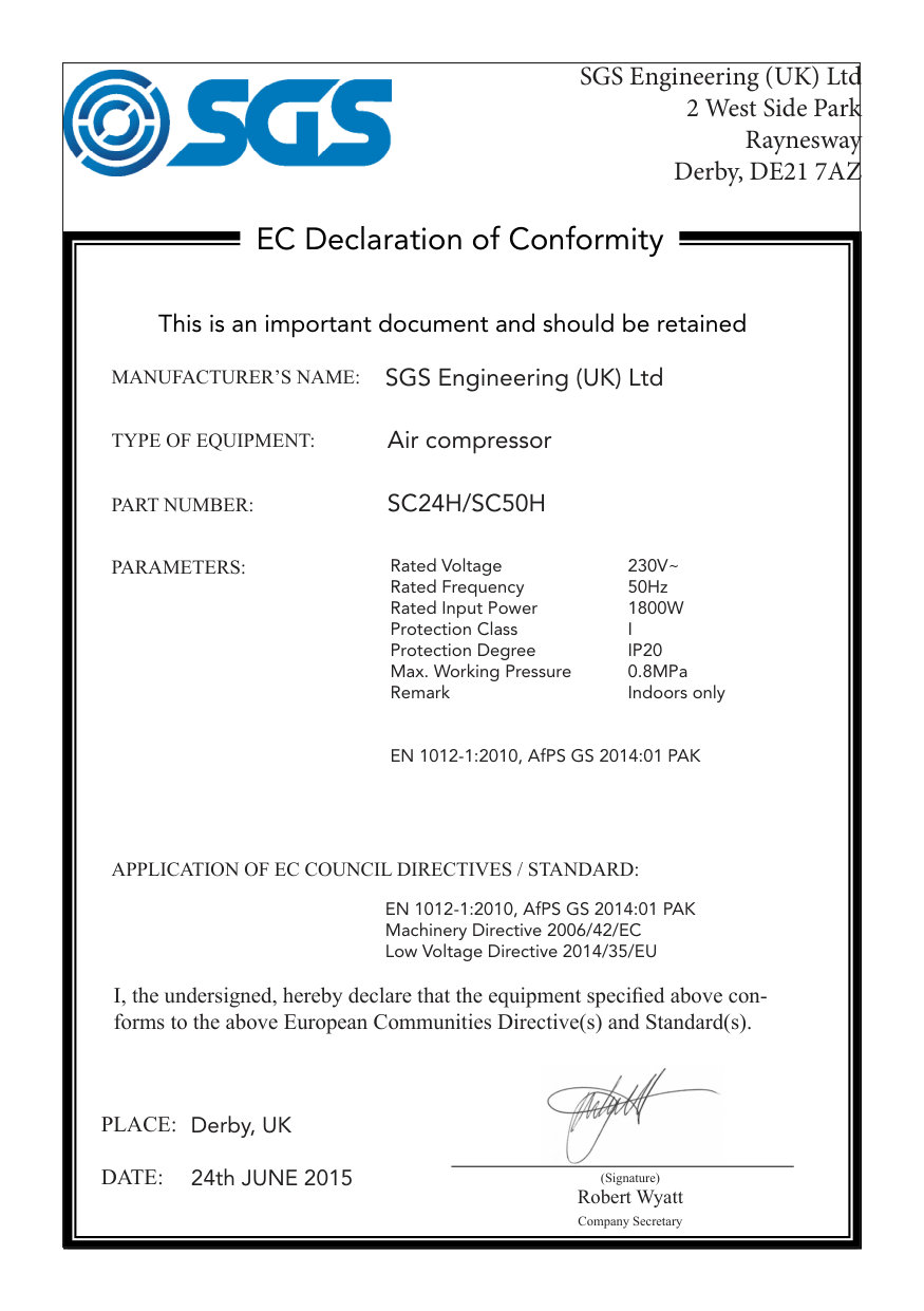
SGS Engineering (UK) Ltd 2 West Side Park Raynesway Derby, DE21 7AZ| |---| |EC Declaration of Conformity
This is an important document and should be retained
MANUFACTURER’S NAME:
TYPE OF EQUIPMENT:
PART NUMBER:
I, the undersigned, hereby declare that the equipment specified above conforms to the above European Communities Directive(s) and Standard(s).
PLACE: DATE: (Signature)
Robert Wyatt Company Secretary
Derby, UK 24th JUNE 2015
SGS Engineering (UK) Ltd

Air compressor
SC24H/SC50H
EN 1012-1:2010, AfPS GS 2014:01 PAK Machinery Directive 2006/42/EC Low Voltage Directive 2014/35/EU
Rated Voltage 230V~ Rated Frequency 50Hz Rated Input Power 1800W Protection Class I Protection Degree IP20 Max. Working Pressure 0.8MPa Remark Indoors only
EN 1012-1:2010, AfPS GS 2014:01 PAK
PARAMETERS:
APPLICATION OF EC COUNCIL DIRECTIVES / STANDARD:|