
Shangzhaoyuan X99 Pr9 Lga 2011 3 Motherboard
Ask AI
— answers from the official manualAnswers from the official manual.
Common questions
Common Questions
10 totalWhat is the power supply requirement?
It's recommended to use a high-power capable power supply of at least 500W to ensure sufficient and stable power delivery to all components on the motherboard. (Page 11)
What should I do if my computer won’t boot?
If the system does not respond, check the CMOS jumper settings, verify CPU compatibility, ensure power connections and switches are correct, confirm proper installation of system panel cables, and test with minimal components. (Page 14)
How do I clear the BIOS?
To reset BIOS settings to default, short the Clear CMOS jumper for a few seconds using a metal object like a screwdriver while ensuring the computer is powered off. (Page 9 and Page 14)
What are the recommended RAM specifications?
The motherboard supports up to 128GB of Dual Channel DDR4 memory in four slots, each supporting a maximum capacity of 32GB at speeds of 2133/2400MHz. (Page 1)
How do I install the M.2 SSD?
Insert the M.2 SSD into the designated slot at a 30-degree angle and secure it with the provided screw. You can switch between NVME M.2/NGFF M.2 mode using the jumper cap. (Page 10)
How do I troubleshoot if my computer keeps restarting?
Clear CMOS jumper, check CPU compatibility, test with a new CPU and RAM, remove graphics card, hard disk, USB devices, and try booting again. (Page 16)
Full Manual
17 pages


X99 PR9-H
User Manual

http://www.91machinist.com/

Any problem with motherboard, please feel free to contact us for help.
Contents Item Specifications................................................................................................1 Structure of Motherboard................................................................................. 2
Install CPU & Fan....................................................................................................3 Install Memory.......................................................................................................4 Install Expansion Card............................................................................................5 Back Panel Connector............................................................................................ 5
PS/2 Port.......................................................................................................... 5 USB 2.0 Port.....................................................................................................6 RJ45 LAN Port...................................................................................................6 Audio Port........................................................................................................6
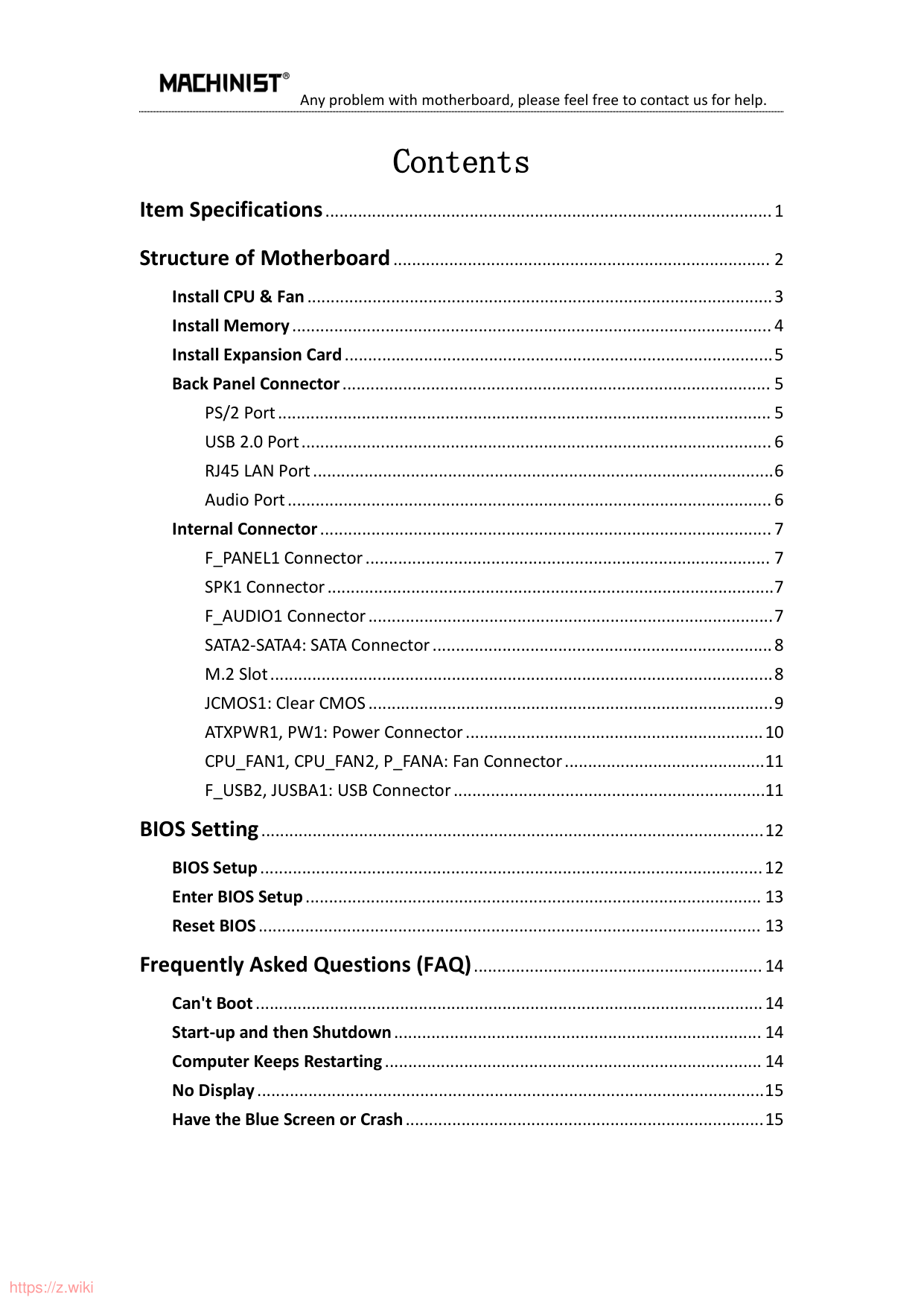
Internal Connector.................................................................................................7 F_PANEL1 Connector....................................................................................... 7 SPK1 Connector................................................................................................7 F_AUDIO1 Connector.......................................................................................7 SATA2-SATA4: SATA Connector.........................................................................8 M.2 Slot............................................................................................................8 JCMOS1: Clear CMOS.......................................................................................9 ATXPWR1, PW1: Power Connector................................................................10 CPU_FAN1, CPU_FAN2, P_FANA: Fan Connector...........................................11 F_USB2, JUSBA1: USB Connector...................................................................11
BIOS Setting............................................................................................................12 BIOS Setup............................................................................................................12 Enter BIOS Setup.................................................................................................. 13 Reset BIOS............................................................................................................ 13
Frequently Asked Questions (FAQ)..............................................................14 Can't Boot.............................................................................................................14 Start-up and then Shutdown............................................................................... 14 Computer Keeps Restarting................................................................................. 14 No Display.............................................................................................................15 Have the Blue Screen or Crash.............................................................................15
Item Specifications
|X99 PR9-H Motherboard|X99 PR9-H Motherboard|X99 PR9-H Motherboard|X99 PR9-H Motherboard| |---|---|---|---| |Processor|Support DDR4 memory with LGA 2011-3 pin series CPUs (e.g. Intel Xeon E5-XXXX-V3, E5-XXXX-V4, and Core i7 5820K/6800K series processors on LGA 2011-v3 socket, etc.)|Support DDR4 memory with LGA 2011-3 pin series CPUs (e.g. Intel Xeon E5-XXXX-V3, E5-XXXX-V4, and Core i7 5820K/6800K series processors on LGA 2011-v3 socket, etc.)|Support DDR4 memory with LGA 2011-3 pin series CPUs (e.g. Intel Xeon E5-XXXX-V3, E5-XXXX-V4, and Core i7 5820K/6800K series processors on LGA 2011-v3 socket, etc.)| |Southbridge|HM55 chipset (or other Intel 5 series chipset)|HM55 chipset (or other Intel 5 series chipset)|HM55 chipset (or other Intel 5 series chipset)| |RAM|Technology|Dual Channel DDR4 Desktop/ECC/RECC/NON-ECC RAM|Dual Channel DDR4 Desktop/ECC/RECC/NON-ECC RAM| |RAM|Maximum Capacity|128GB (32GB*4)|128GB (32GB*4)| |RAM|Memory Slot|4* DDR4 DIMM (2133/2400MHz)|4* DDR4 DIMM (2133/2400MHz)| |Back Panel I/O Ports|Display Interface|0|0| |Back Panel I/O Ports|USB|6* USB 2.0;|6* USB 2.0;| |Back Panel I/O Ports|Ethernet|1 * Gigabits LAN Card|1 * Gigabits LAN Card| |Back Panel I/O Ports|Audio Jacks|3* Audio jacks(Line-in、Line-out、Mic-in)|3* Audio jacks(Line-in、Line-out、Mic-in)| |Internal I/O Ports|USB|2* USB 2.0|2* USB 2.0|
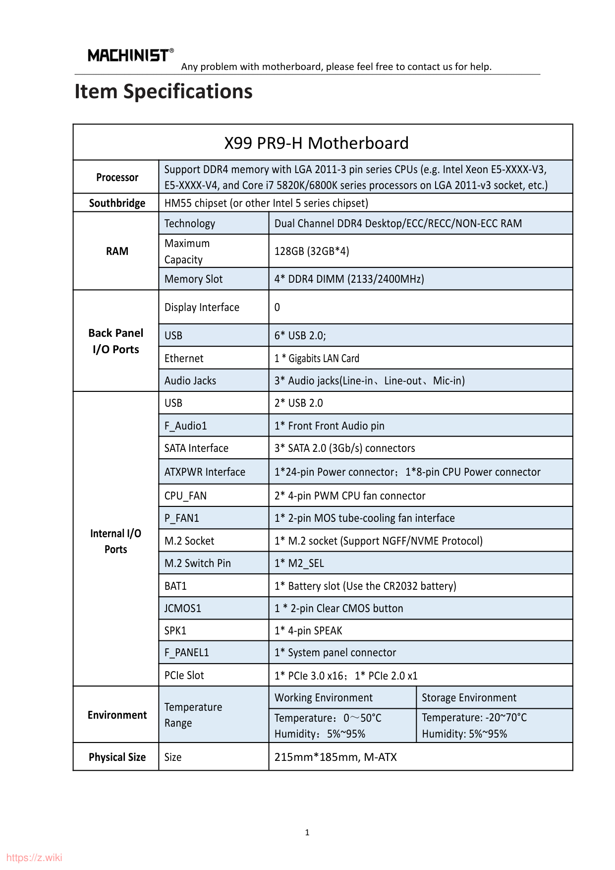
|Internal I/O Ports|F_Audio1|1* Front Front Audio pin|1* Front Front Audio pin| |Internal I/O Ports|SATA Interface|3* SATA 2.0 (3Gb/s) connectors|3* SATA 2.0 (3Gb/s) connectors| |Internal I/O Ports|ATXPWR Interface|1*24-pin Power connector;1*8-pin CPU Power connector|1*24-pin Power connector;1*8-pin CPU Power connector| |Internal I/O Ports|CPU_FAN|2* 4-pin PWM CPU fan connector|2* 4-pin PWM CPU fan connector| |Internal I/O Ports|P_FAN1|1* 2-pin MOS tube-cooling fan interface|1* 2-pin MOS tube-cooling fan interface| |Internal I/O Ports|M.2 Socket|1* M.2 socket (Support NGFF/NVME Protocol)|1* M.2 socket (Support NGFF/NVME Protocol)| |Internal I/O Ports|M.2 Switch Pin|1* M2_SEL|1* M2_SEL| |Internal I/O Ports|BAT1|1* Battery slot (Use the CR2032 battery)|1* Battery slot (Use the CR2032 battery)| |Internal I/O Ports|JCMOS1|1 * 2-pin Clear CMOS button|1 * 2-pin Clear CMOS button| |Internal I/O Ports|SPK1|1* 4-pin SPEAK|1* 4-pin SPEAK| |Internal I/O Ports|F_PANEL1|1* System panel connector|1* System panel connector| |Internal I/O Ports|PCIe Slot|1* PCIe 3.0 x16;1* PCIe 2.0 x1|1* PCIe 3.0 x16;1* PCIe 2.0 x1| |Environment|Temperature Range|Working Environment|Storage Environment| |Environment|Temperature Range|Temperature:0~50°C Humidity:5%~95%|Temperature: -20~70°C Humidity: 5%~95%| |Physical Size|Size|215mm*185mm, M-ATX|215mm*185mm, M-ATX|
Structure of Motherboard

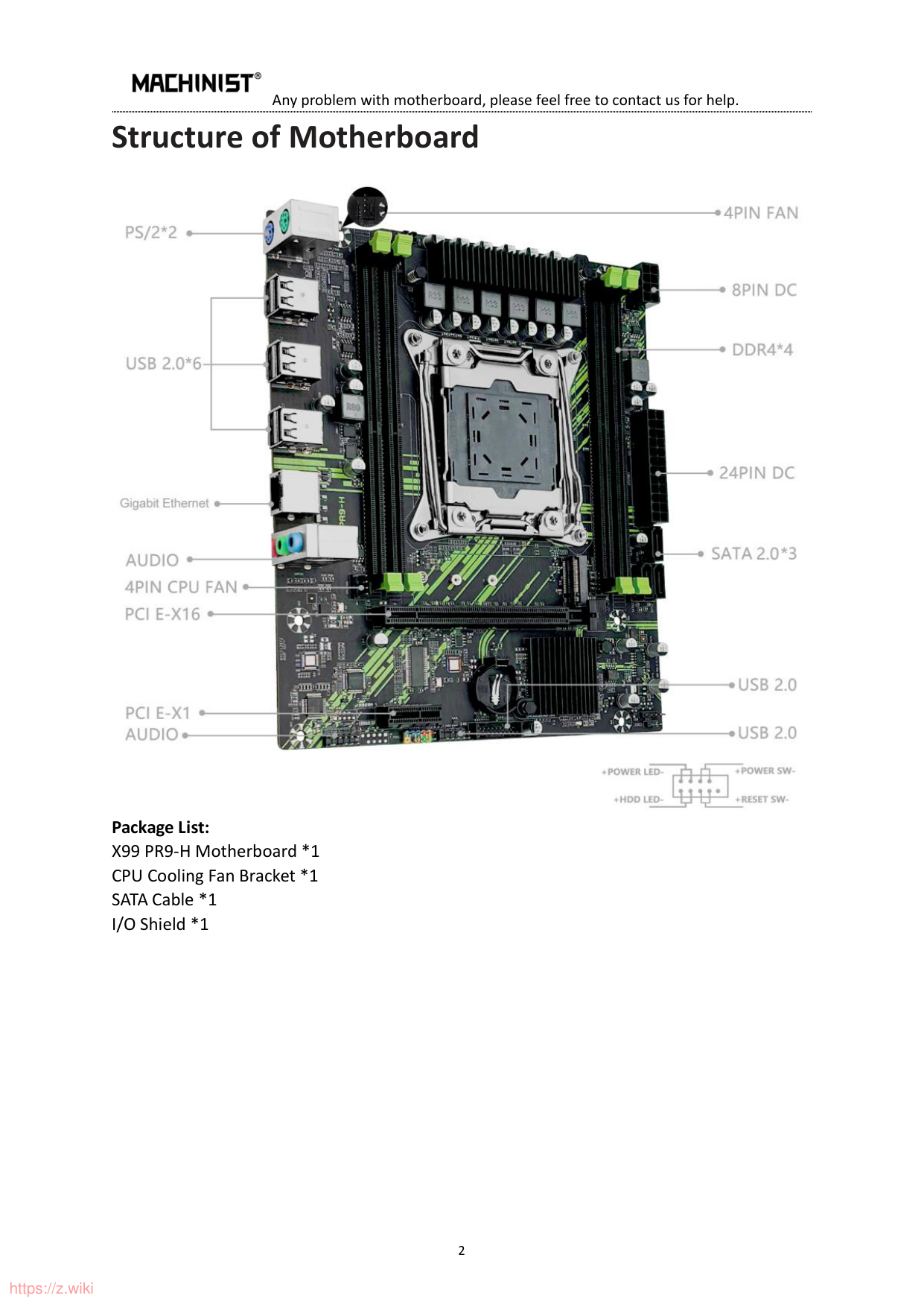
Package List: X99 PR9-H Motherboard *1 CPU Cooling Fan Bracket *1 SATA Cable *1 I/O Shield *1
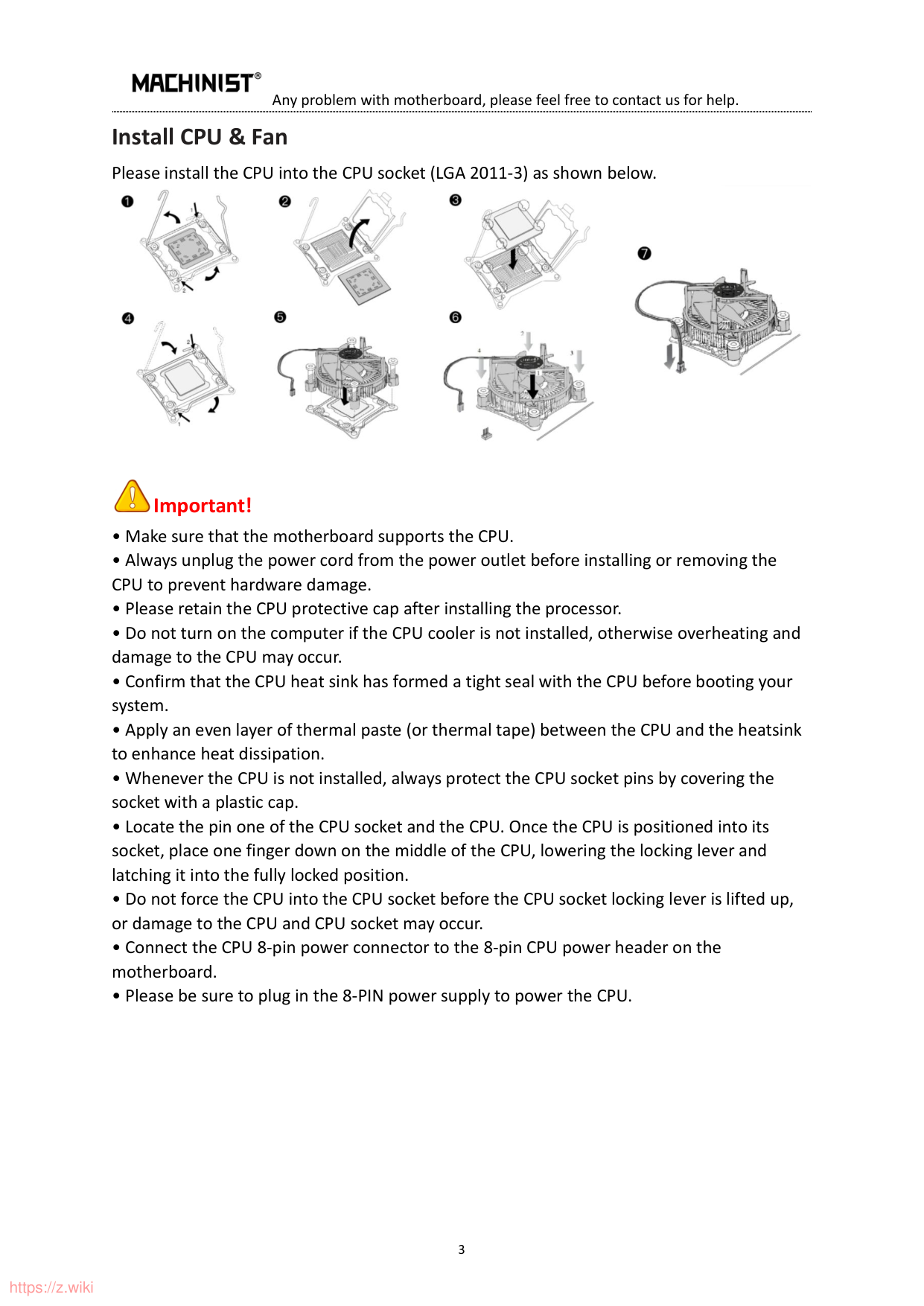
Install CPU & Fan Please install the CPU into the CPU socket (LGA 2011-3) as shown below.


##### Important!
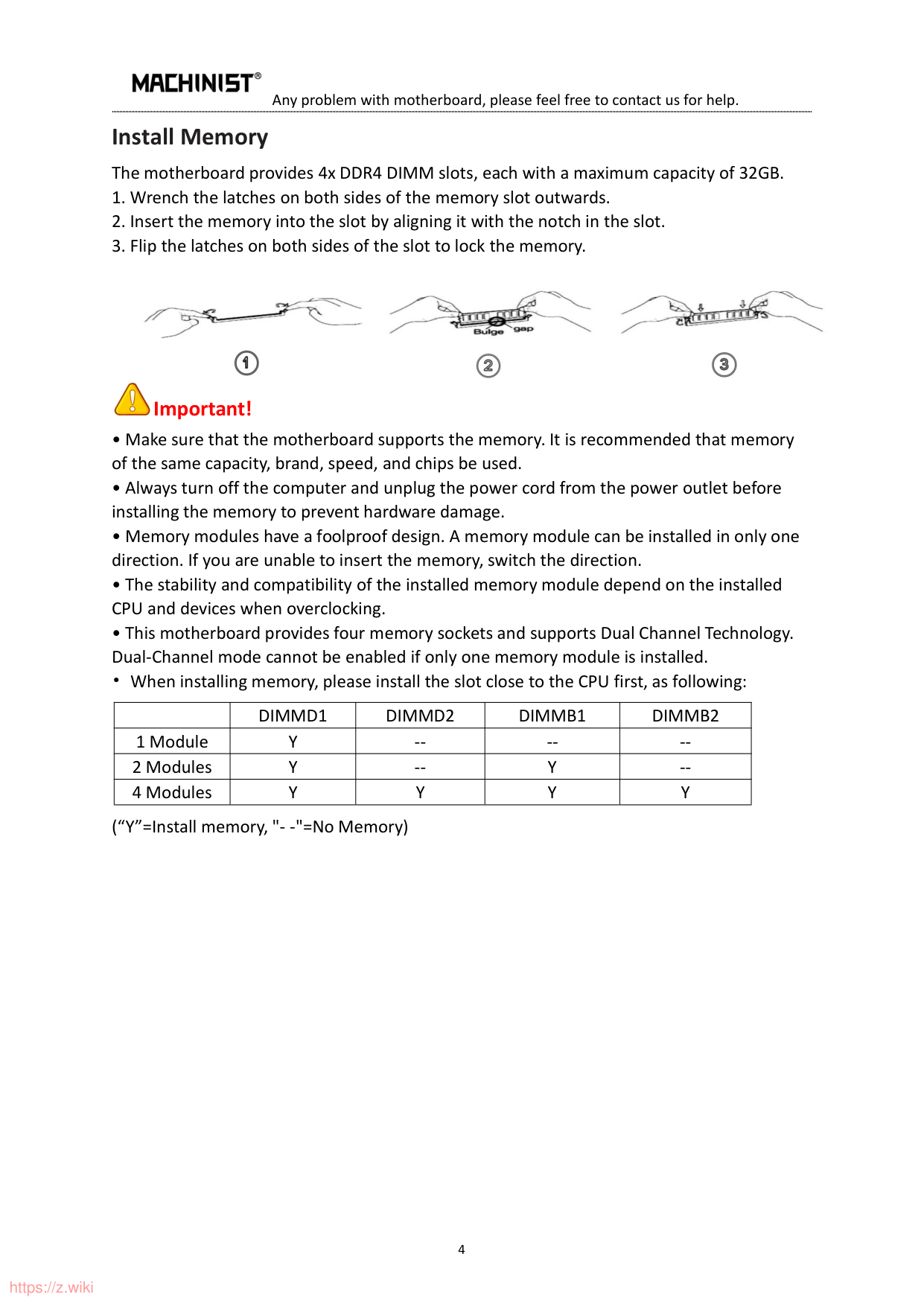
Install Memory The motherboard provides 4x DDR4 DIMM slots, each with a maximum capacity of 32GB.


##### Important!
| |DIMMD1|DIMMD2|DIMMB1|DIMMB2| |---|---|---|---|---| |1 Module|Y|--|--|--| |2 Modules|Y|--|Y|--| |4 Modules|Y|Y|Y|Y|
(“Y”=Install memory, "- -"=No Memory)
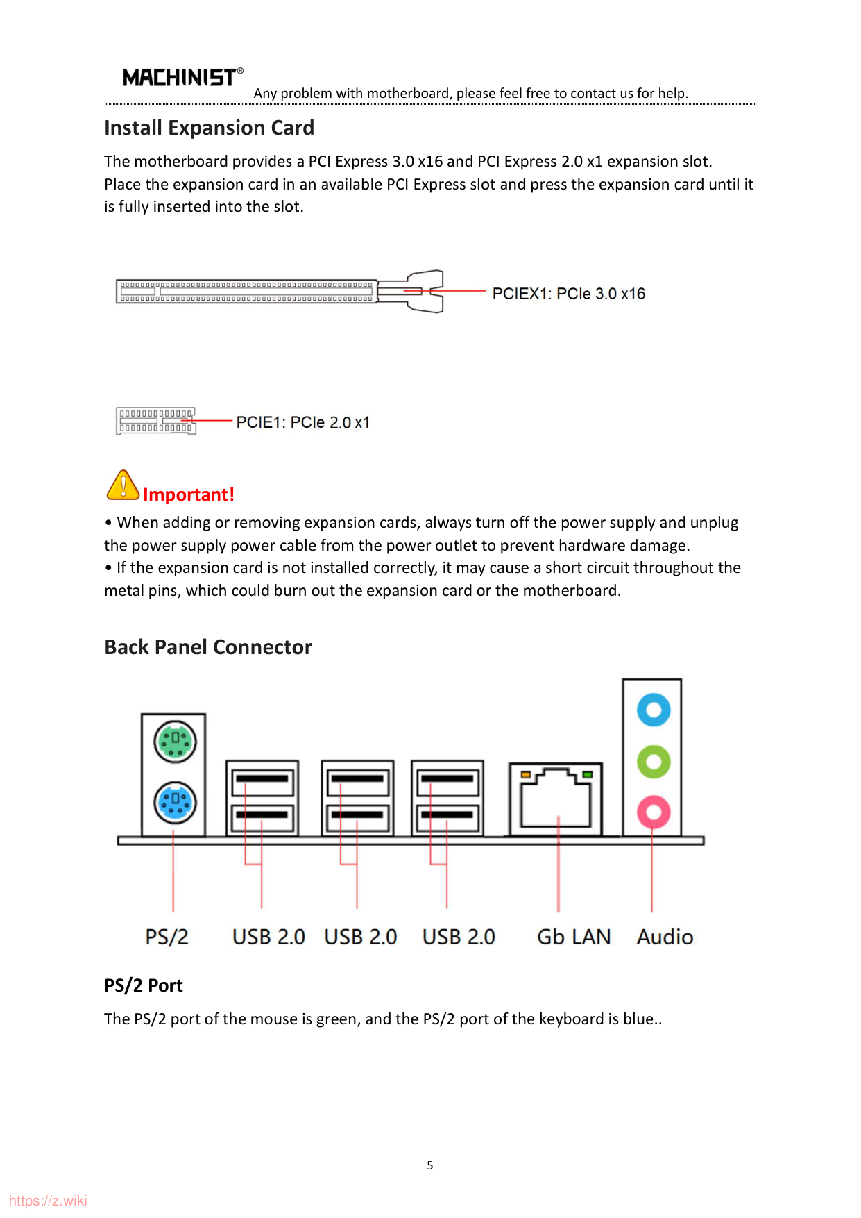
#### Install Expansion Card
The motherboard provides a PCI Express 3.0 x16 and PCI Express 2.0 x1 expansion slot. Place the expansion card in an available PCI Express slot and press the expansion card until it is fully inserted into the slot.


##### Important!
#### Back Panel Connector

PS/2 Port The PS/2 port of the mouse is green, and the PS/2 port of the keyboard is blue..
##### USB 2.0 Port
It comes with 6pcs USB 2.0 interfaces, those USB ports with 480Mbps fast speed and hot-swappable function allow you to connect multiple USB 2.0 devices.
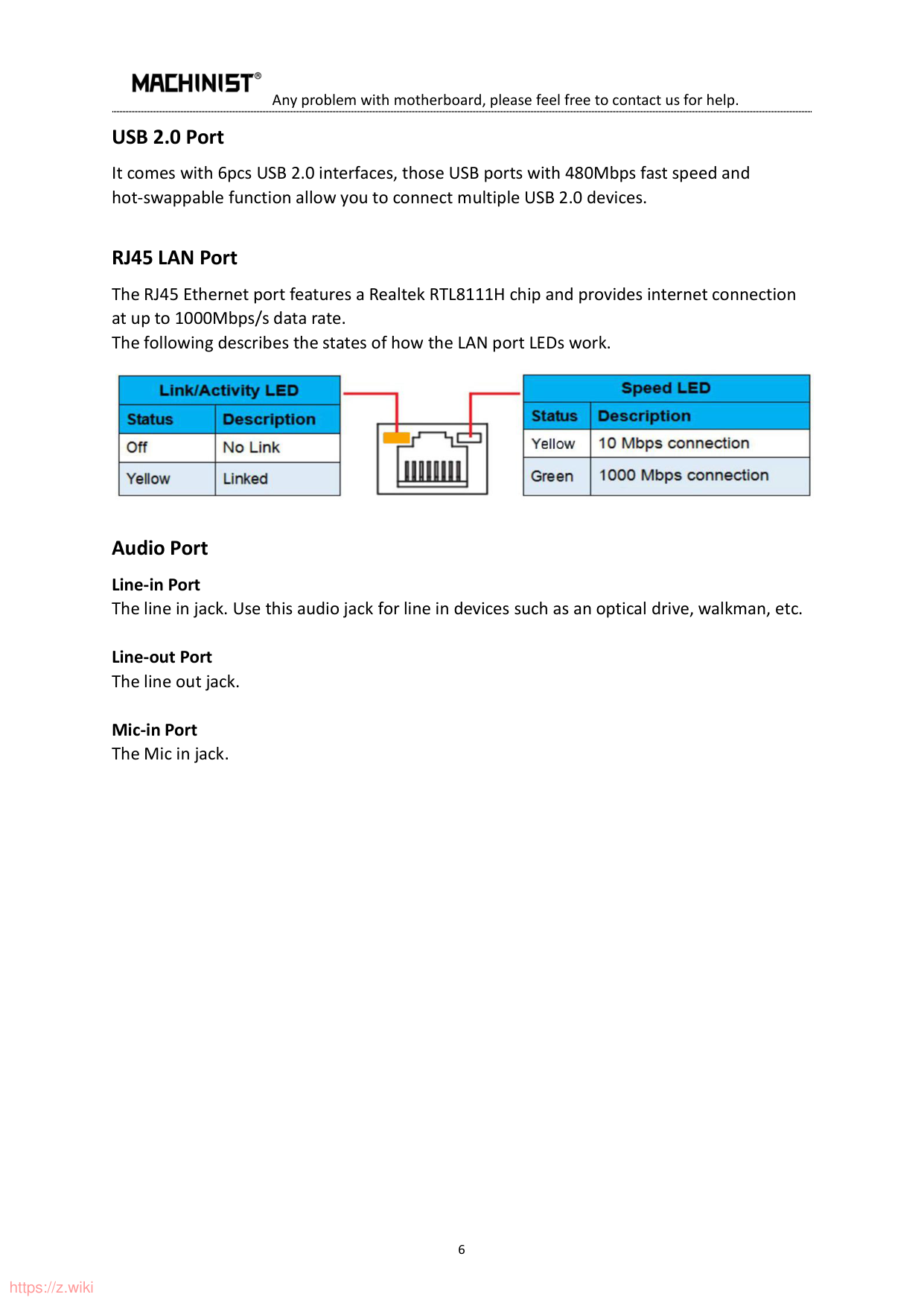
##### RJ45 LAN Port
The RJ45 Ethernet port features a Realtek RTL8111H chip and provides internet connection at up to 1000Mbps/s data rate. The following describes the states of how the LAN port LEDs work.

Audio Port Line-in Port The line in jack. Use this audio jack for line in devices such as an optical drive, walkman, etc.
Line-out Port The line out jack.
Mic-in Port The Mic in jack.
#### Internal Connector F_PANEL1 Connector

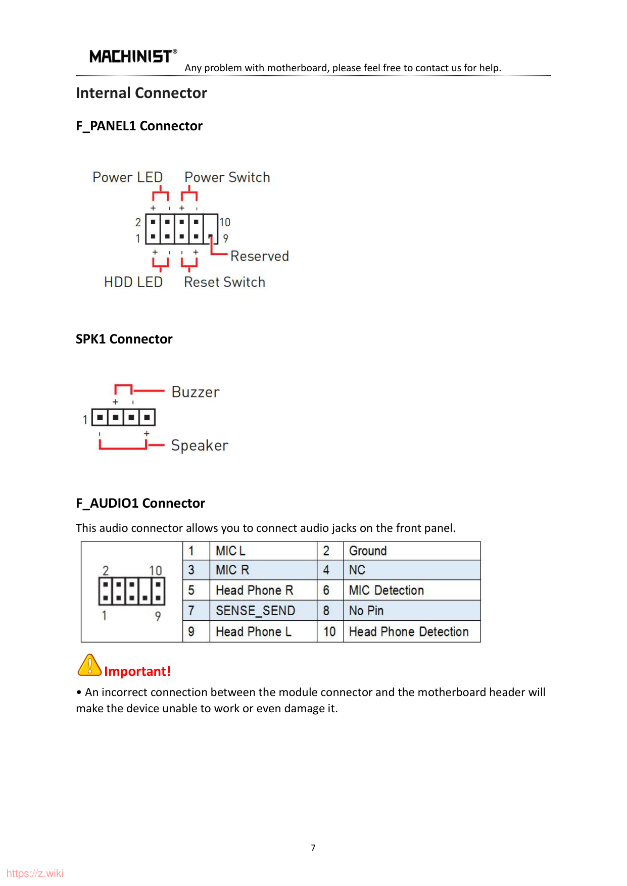
##### SPK1 Connector

F_AUDIO1 Connector This audio connector allows you to connect audio jacks on the front panel.


##### Important!
SATA2-SATA4: SATA Connector SATA2-SATA4: 3Pcs SATA 2.0 Connectors; these SATA II connectors are SATA 3Gb/s interface ports. Each SATA connector supports a single SATA device.

##### M.2 Slot
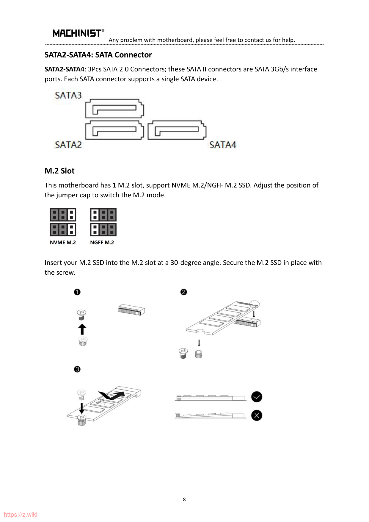
This motherboard has 1 M.2 slot, support NVME M.2/NGFF M.2 SSD. Adjust the position of the jumper cap to switch the M.2 mode.

Insert your M.2 SSD into the M.2 slot at a 30-degree angle. Secure the M.2 SSD in place with the screw.

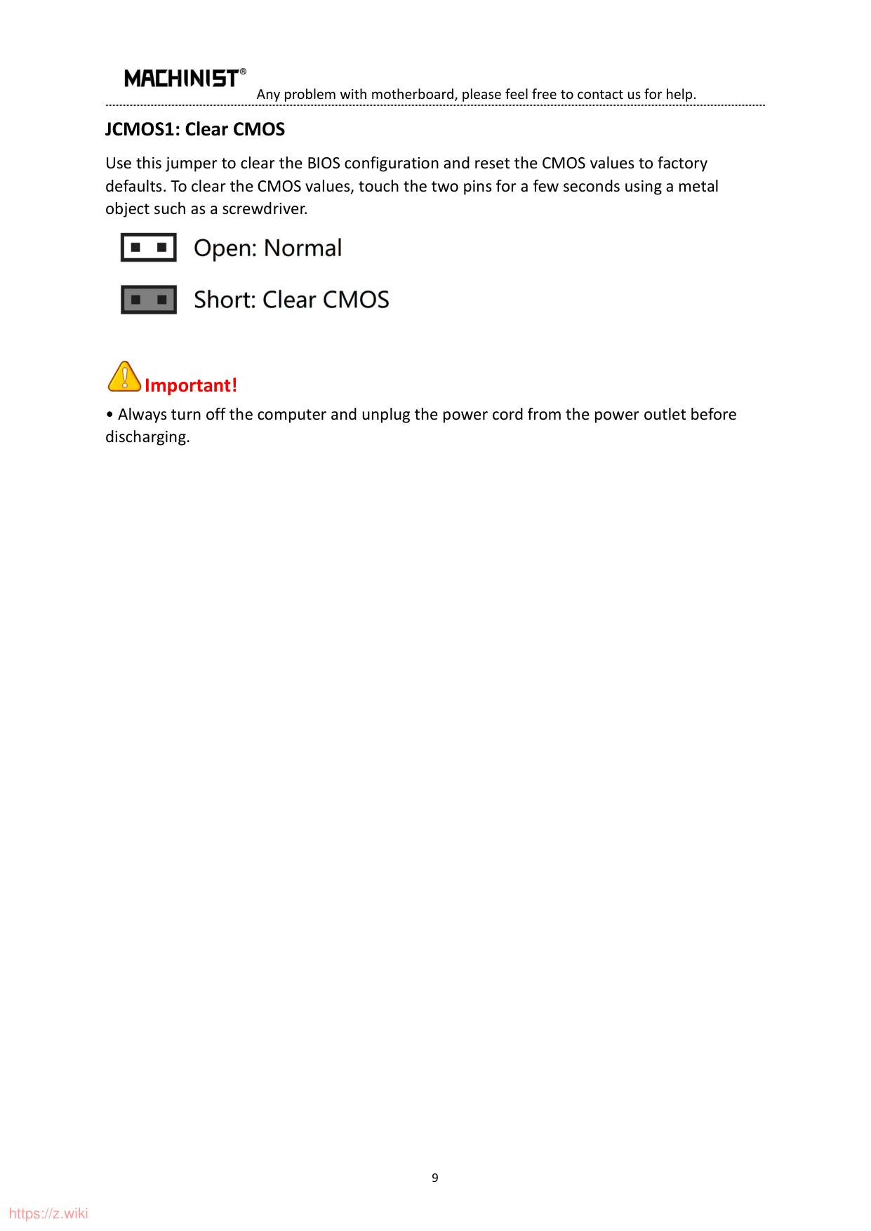
##### JCMOS1: Clear CMOS
Use this jumper to clear the BIOS configuration and reset the CMOS values to factory defaults. To clear the CMOS values, touch the two pins for a few seconds using a metal object such as a screwdriver.


##### Important!
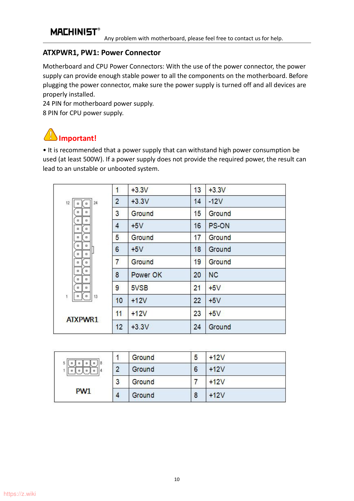
##### ATXPWR1, PW1: Power Connector
Motherboard and CPU Power Connectors: With the use of the power connector, the power supply can provide enough stable power to all the components on the motherboard. Before plugging the power connector, make sure the power supply is turned off and all devices are properly installed. 24 PIN for motherboard power supply. 8 PIN for CPU power supply.

##### Important!

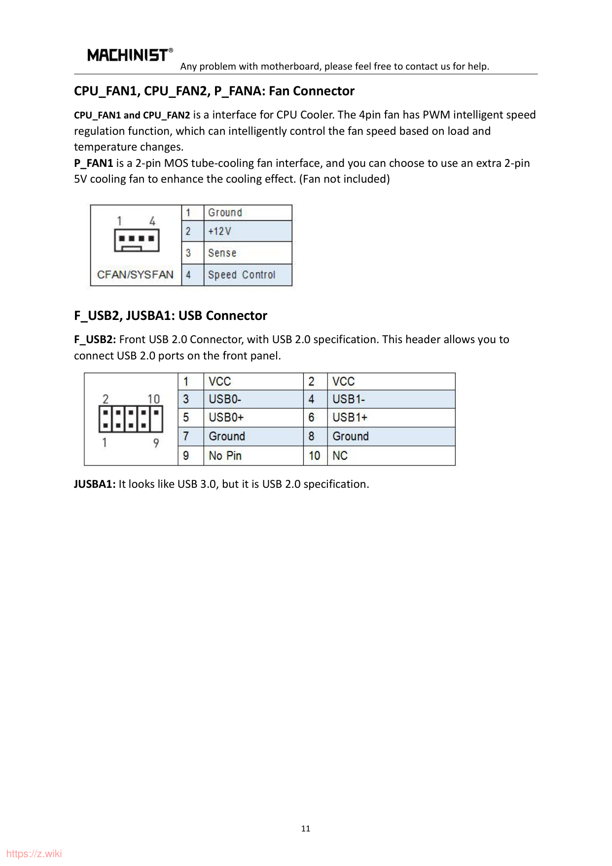
CPU_FAN1, CPU_FAN2, P_FANA: Fan Connector CPU_FAN1 and CPU_FAN2 is a interface for CPU Cooler. The 4pin fan has PWM intelligent speed regulation function, which can intelligently control the fan speed based on load and temperature changes. P_FAN1 is a 2-pin MOS tube-cooling fan interface, and you can choose to use an extra 2-pin 5V cooling fan to enhance the cooling effect. (Fan not included)

F_USB2, JUSBA1: USB Connector F_USB2: Front USB 2.0 Connector, with USB 2.0 specification. This header allows you to connect USB 2.0 ports on the front panel.

JUSBA1: It looks like USB 3.0, but it is USB 2.0 specification.
BIOS Setting
BIOS (Basic Input and Output System) records the hardware parameters of the system in the CMOS on the motherboard. BIOS identifies, configures, tests, and connects computer hardware to the OS immediately after a computer is turned on.. Its major functions include conducting the Power-On Self-Test (POST) during system startup, saving system parameters, loading the operating system, etc. BIOS includes a BIOS Setup program that allows the user to modify basic system configuration settings or to activate certain system features. When the power is turned off, the battery on the motherboard supplies the necessary power to the CMOS to keep the configuration values in the CMOS.

##### Important!
BIOS Setup
The default settings offer optimal performance for system stability in normal conditions. Using the default settings is recommended (unless you need to) to prevent system instability or other unexpected results. Inadequately altering the settings may result in the system's failure to boot.

Important!
#### Enter BIOS Setup
When the computer is turned on, BIOS enters the self-test process. The following message will display after the self-test is completed: Press the " DEL " key to enter the BIOS Setup Menu. Or use the “ Quick Boot Key” to press the F11.
If this message disappears before you press the key, you can turn it off and then turn on your computer or press

##### Important!
Reset BIOS
When you need to restore the default BIOS settings to resolve certain issues, the following step for quick reset the BIOS:
∙ Short the Clear CMOS jumper on the motherboard.

Important!
Frequently Asked Questions (FAQ)
#### Can't Boot
That means pressing the boot button, but the computer does not respond, the fan does not rotate, and the indicator light does not light. There are seven ways to troubleshoot as below:
#### Start-up and then Shutdown
That means pressing the power button and the fan will immediately turn off after rotating once only; And there are five ways to troubleshoot as below:
#### Computer Keeps Restarting
That means your computer automatically restarts or endlessly falls into the reboot loop. There are five ways to troubleshoot as below:
No Display There are two states for monitor no display as below:
Have the Blue Screen or Crash There are six ways to troubleshoot as below: