
Ask AI
— answers from the official manualAnswers from the official manual.
Common questions
Common Questions
20 totalIs STM32CubeProgrammer suitable for use in production programming?
STM32CubeProgrammer is intended for development and pre-production use only; its use in production is neither supported nor recommended by ST. For production programming, ST relies on its authorized programming partner network. Pre-production use is tolerated only when these partners do not yet support the specific STM32 devices concerned. (Page 12)
What are the system requirements for STM32CubeProgrammer?
Supported operating systems include Windows 10/11, Linux Ubuntu LTS 22.04 and 24.04 with Fedora 43, and macOS versions 15 (Sequoia) and 26 (Tahoe), both in x86_64 and ARM-aarch64 architectures.
How do I install the DFU driver for STM32CubeProgrammer?
Install the STM32CubeProgrammer DFU driver by running the 'STM32 Bootloader.bat' file located in the DFU driver folder. Ensure to uninstall any existing DfuSe drivers before reinstalling.
How do I factory reset the STM32CubeProgrammer Option Bytes panel?
To restore option bytes to their default settings, select 'Reset MCU to Factory Settings' from the 'Read' button menu in the Options Bytes tab. This initiates a recovery process with status updates.
How do I erase an external flash memory using STM32CubeProgrammer?
Select sectors or perform full chip erasure on the 'External flash erasing' tab, choosing from the displayed start address and size for each sector. The process initiates upon clicking the 'Erase selected sectors' button.
What are the steps to develop a customized loader for external memory with STM32CubeProgrammer?
Update device information in StorageInfo structure, rewrite functions in Loader_Src.c file, and change output file name. Compile the project, rename the ELF file to ".stldr", and place it under 'bin/ExternalLoader' directory.
Show 14 more questions
How do I update STM32CubeProgrammer software from console?
How do I install STM32CubeProgrammer on Windows?
How do I use STM32CubeProgrammer updater?
How do I erase full chip memory using STM32CubeProgrammer?
What operating systems are supported by STM32CubeProgrammer?
How do I install the DFU driver for USB DFU mode on Windows?
How do I install STM32CubeProgrammer on Linux?
How do I install the ST-LINK driver on Windows?
How do I update STM32CubeProgrammer to the latest version?
How do I install the STM32CubeProgrammer software on Linux?
What connection interfaces does STM32CubeProgrammer support?
What file formats are supported for programming flash memory?
How do I reset option bytes to factory default values?
How do I uninstall STM32CubeProgrammer on Windows?
Full Manual
186 pages
February 2026 UM2237 Rev 30 1/186 1
Um2237
User manual STM32CubeProgrammer software description Introduction STM32CubeProgrammer (STM32CubeProg) provides an all-in-one software tool to program STM32 devices in any environment: multi-OS, graphical user interface, or command line interface. It supports a wide choice of connections (JTAG, SWD, USB, UART, SPI, CAN, I2C), with manual operation or automation through scripting. This document details the hardware and software environment prerequisites, as well as the available STM32CubeProgrammer software features. www.st.com
Contents
Um2237
2/186 UM2237 Rev 30 Contents 1 Getting started . . . . . . . . . . . . . . . . . . . . . . . . . . . . . . . . . . . . . . . . . . . . . 12 1.1 System requirements . . . . . . . . . . . . . . . . . . . . . . . . . . . . . . . . . . . . . . . . 12 1.2 Installing STM32CubeProgrammer . . . . . . . . . . . . . . . . . . . . . . . . . . . . . 13 1.2.1 Linux install . . . . . . . . . . . . . . . . . . . . . . . . . . . . . . . . . . . . . . . . . . . . . . 13 1.2.2 Windows install . . . . . . . . . . . . . . . . . . . . . . . . . . . . . . . . . . . . . . . . . . . 13 1.2.3 macOS install . . . . . . . . . . . . . . . . . . . . . . . . . . . . . . . . . . . . . . . . . . . . . 13 1.2.4 DFU driver . . . . . . . . . . . . . . . . . . . . . . . . . . . . . . . . . . . . . . . . . . . . . . . 14 1.2.5 ST-LINK driver . . . . . . . . . . . . . . . . . . . . . . . . . . . . . . . . . . . . . . . . . . . . 15 1.2.6 Segger Jlink/Flasher library . . . . . . . . . . . . . . . . . . . . . . . . . . . . . . . . . . 15 1.2.7 Installing STM32CubeProgrammer from command line . . . . . . . . . . . . 16 1.2.8 Automatic/Silent installation mode . . . . . . . . . . . . . . . . . . . . . . . . . . . . . 16 1.2.9 Uninstalling STM32CubeProgrammer standalone version . . . . . . . . . . 18 1.3 Language preference . . . . . . . . . . . . . . . . . . . . . . . . . . . . . . . . . . . . . . . . 18 1.4 Updater . . . . . . . . . . . . . . . . . . . . . . . . . . . . . . . . . . . . . . . . . . . . . . . . . . 18 1.4.1 Update steps . . . . . . . . . . . . . . . . . . . . . . . . . . . . . . . . . . . . . . . . . . . . . 18 1.4.2 Proxy settings . . . . . . . . . . . . . . . . . . . . . . . . . . . . . . . . . . . . . . . . . . . . 19 1.4.3 Check for updates . . . . . . . . . . . . . . . . . . . . . . . . . . . . . . . . . . . . . . . . . 20 2 STM32CubeProgrammer user interface for MCUs . . . . . . . . . . . . . . . . 22 2.1 Main window . . . . . . . . . . . . . . . . . . . . . . . . . . . . . . . . . . . . . . . . . . . . . . . 22 2.1.1 Main menu . . . . . . . . . . . . . . . . . . . . . . . . . . . . . . . . . . . . . . . . . . . . . . . 22 2.1.2 Log panel . . . . . . . . . . . . . . . . . . . . . . . . . . . . . . . . . . . . . . . . . . . . . . . . 23 2.1.3 Progress bar . . . . . . . . . . . . . . . . . . . . . . . . . . . . . . . . . . . . . . . . . . . . . 24 2.1.4 Target configuration panel . . . . . . . . . . . . . . . . . . . . . . . . . . . . . . . . . . . 24 2.2 Memory & file edition . . . . . . . . . . . . . . . . . . . . . . . . . . . . . . . . . . . . . . . . 34 2.2.1 Reading and displaying target memory . . . . . . . . . . . . . . . . . . . . . . . . . 34 2.2.2 Reading and displaying a file . . . . . . . . . . . . . . . . . . . . . . . . . . . . . . . . . 35 2.3 Memory programming and erasing . . . . . . . . . . . . . . . . . . . . . . . . . . . . . 35 2.3.1 Internal flash memory programming . . . . . . . . . . . . . . . . . . . . . . . . . . . 35 2.3.2 External flash memory programming . . . . . . . . . . . . . . . . . . . . . . . . . . . 37 2.3.3 Developing customized loaders for external memory . . . . . . . . . . . . . . 37 2.3.4 External memory programming with bootloader interfaces on GUI . . . . 40 2.4 Option bytes . . . . . . . . . . . . . . . . . . . . . . . . . . . . . . . . . . . . . . . . . . . . . . . 40
UM2237 Rev 30 3/186
Um2237
Contents 6 2.4.1 Synthetic option bytes view . . . . . . . . . . . . . . . . . . . . . . . . . . . . . . . . . . 41 2.4.2 Recovery button . . . . . . . . . . . . . . . . . . . . . . . . . . . . . . . . . . . . . . . . . . . 42 2.4.3 Export/import option bytes . . . . . . . . . . . . . . . . . . . . . . . . . . . . . . . . . . . 42 2.4.4 MCU unlock (specific for the STM32WL series) . . . . . . . . . . . . . . . . . . 43 2.4.5 Debug authentication default configuration . . . . . . . . . . . . . . . . . . . . . . 43 2.4.6 Debug authentication configuration (STM32H503 only) . . . . . . . . . . . . 44 2.5 Automatic mode . . . . . . . . . . . . . . . . . . . . . . . . . . . . . . . . . . . . . . . . . . . . 44 2.6 In application programming (IAP/USBx) . . . . . . . . . . . . . . . . . . . . . . . . . . 49 2.7 Flash the wireless stack using the graphical interface . . . . . . . . . . . . . . . 49 2.7.1 FUS/stack upgrade . . . . . . . . . . . . . . . . . . . . . . . . . . . . . . . . . . . . . . . . 49 2.7.2 Key provisioning . . . . . . . . . . . . . . . . . . . . . . . . . . . . . . . . . . . . . . . . . . 51 2.8 Serial wire viewer (SWV) . . . . . . . . . . . . . . . . . . . . . . . . . . . . . . . . . . . . . 51 2.9 Secure programming interface . . . . . . . . . . . . . . . . . . . . . . . . . . . . . . . . . 53 2.9.1 Introduction . . . . . . . . . . . . . . . . . . . . . . . . . . . . . . . . . . . . . . . . . . . . . . 53 2.9.2 RDP regression with password . . . . . . . . . . . . . . . . . . . . . . . . . . . . . . . 53 2.9.3 SFI/SFIx . . . . . . . . . . . . . . . . . . . . . . . . . . . . . . . . . . . . . . . . . . . . . . . . . 55 2.9.4 SSP . . . . . . . . . . . . . . . . . . . . . . . . . . . . . . . . . . . . . . . . . . . . . . . . . . . . 59 2.9.5 OBKey provisioning . . . . . . . . . . . . . . . . . . . . . . . . . . . . . . . . . . . . . . . . 61 2.9.6 OTP provisioning panel . . . . . . . . . . . . . . . . . . . . . . . . . . . . . . . . . . . . . 62 2.9.7 Debug authentication . . . . . . . . . . . . . . . . . . . . . . . . . . . . . . . . . . . . . . . 63 2.10 STM32CubeProgrammer Script Manager platform for MCUs . . . . . . . . . 64 2.10.1 Introduction for the usage scenarios of Script Manager . . . . . . . . . . . . 64 2.10.2 Script Manager usage . . . . . . . . . . . . . . . . . . . . . . . . . . . . . . . . . . . . . . 64 2.10.3 Loops and conditional statements . . . . . . . . . . . . . . . . . . . . . . . . . . . . . 70 2.11 DFU IAP/USBx with custom PID and VID . . . . . . . . . . . . . . . . . . . . . . . . 72 2.12 SigFox™ credentials . . . . . . . . . . . . . . . . . . . . . . . . . . . . . . . . . . . . . . . . 74 2.13 Register Viewer . . . . . . . . . . . . . . . . . . . . . . . . . . . . . . . . . . . . . . . . . . . . 74 2.14 Hard Fault analyzer . . . . . . . . . . . . . . . . . . . . . . . . . . . . . . . . . . . . . . . . . 75 2.14.1 Description . . . . . . . . . . . . . . . . . . . . . . . . . . . . . . . . . . . . . . . . . . . . . . . 75 2.14.2 Example . . . . . . . . . . . . . . . . . . . . . . . . . . . . . . . . . . . . . . . . . . . . . . . . . 76 2.14.3 Fault analyzer note . . . . . . . . . . . . . . . . . . . . . . . . . . . . . . . . . . . . . . . . 77 2.14.4 Secure Fault analyzer for Cortex-M33 . . . . . . . . . . . . . . . . . . . . . . . . . . 78 2.15 Fill memory command . . . . . . . . . . . . . . . . . . . . . . . . . . . . . . . . . . . . . . . 79 2.16 Fill memory operation . . . . . . . . . . . . . . . . . . . . . . . . . . . . . . . . . . . . . . . . 80 2.17 Blank check command . . . . . . . . . . . . . . . . . . . . . . . . . . . . . . . . . . . . . . . 82
Contents
Um2237
4/186 UM2237 Rev 30 2.18 Blank check operation . . . . . . . . . . . . . . . . . . . . . . . . . . . . . . . . . . . . . . . 83 2.19 Compare flash memory with file . . . . . . . . . . . . . . . . . . . . . . . . . . . . . . . . 87 2.20 Comparison between two files . . . . . . . . . . . . . . . . . . . . . . . . . . . . . . . . . 92 2.21 LiveUpdate feature . . . . . . . . . . . . . . . . . . . . . . . . . . . . . . . . . . . . . . . . . . 96 2.22 Calculator . . . . . . . . . . . . . . . . . . . . . . . . . . . . . . . . . . . . . . . . . . . . . . . . . 97 2.23 Import/Export project settings . . . . . . . . . . . . . . . . . . . . . . . . . . . . . . . . . . 98 2.24 OTP programming window for STM32N6 . . . . . . . . . . . . . . . . . . . . . . . . 99 2.25 External flash memory window for STM32N6 . . . . . . . . . . . . . . . . . . . . 100 2.26 STM32V8 NVM programming constraints . . . . . . . . . . . . . . . . . . . . . . . 100 2.27 Export MCU memory map . . . . . . . . . . . . . . . . . . . . . . . . . . . . . . . . . . . 101 3 STM32CubeProgrammer command line interface (CLI) for MCUs . . 103 3.1 Command line usage . . . . . . . . . . . . . . . . . . . . . . . . . . . . . . . . . . . . . . . 103 3.2 Generic commands . . . . . . . . . . . . . . . . . . . . . . . . . . . . . . . . . . . . . . . . 103 3.2.1 Connect command . . . . . . . . . . . . . . . . . . . . . . . . . . . . . . . . . . . . . . . . 103 3.2.2 Erase command . . . . . . . . . . . . . . . . . . . . . . . . . . . . . . . . . . . . . . . . . . 112 3.2.3 Download command . . . . . . . . . . . . . . . . . . . . . . . . . . . . . . . . . . . . . . 113 3.2.4 Verify command . . . . . . . . . . . . . . . . . . . . . . . . . . . . . . . . . . . . . . . . . . 114 3.2.5 Download 32-bit data command . . . . . . . . . . . . . . . . . . . . . . . . . . . . . 114 3.2.6 Read command . . . . . . . . . . . . . . . . . . . . . . . . . . . . . . . . . . . . . . . . . . 114 3.2.7 Start command . . . . . . . . . . . . . . . . . . . . . . . . . . . . . . . . . . . . . . . . . . 116 3.2.8 Debug commands . . . . . . . . . . . . . . . . . . . . . . . . . . . . . . . . . . . . . . . . 116 3.2.9 List command . . . . . . . . . . . . . . . . . . . . . . . . . . . . . . . . . . . . . . . . . . . 117 3.2.10 SWD Multidrop . . . . . . . . . . . . . . . . . . . . . . . . . . . . . . . . . . . . . . . . . . . 117 3.2.11 QuietMode command . . . . . . . . . . . . . . . . . . . . . . . . . . . . . . . . . . . . . 119 3.2.12 Bootloader reset command . . . . . . . . . . . . . . . . . . . . . . . . . . . . . . . . . 119 3.2.13 Verbosity command . . . . . . . . . . . . . . . . . . . . . . . . . . . . . . . . . . . . . . . 119 3.2.14 Log command . . . . . . . . . . . . . . . . . . . . . . . . . . . . . . . . . . . . . . . . . . . 120 3.2.15 External loader command . . . . . . . . . . . . . . . . . . . . . . . . . . . . . . . . . . 121 3.2.16 External loader command with bootloader interface . . . . . . . . . . . . . . 122 3.2.17 Read unprotect command . . . . . . . . . . . . . . . . . . . . . . . . . . . . . . . . . . 123 3.2.18 TZ regression command . . . . . . . . . . . . . . . . . . . . . . . . . . . . . . . . . . . 123 3.2.19 Option bytes command . . . . . . . . . . . . . . . . . . . . . . . . . . . . . . . . . . . . 123 3.2.20 Safety lib command . . . . . . . . . . . . . . . . . . . . . . . . . . . . . . . . . . . . . . . 123 3.2.21 Secure programming SFI specific commands . . . . . . . . . . . . . . . . . . . 128 3.2.22 Secure programming SFIx specific commands . . . . . . . . . . . . . . . . . . 129
UM2237 Rev 30 5/186
Um2237
Contents 6 3.2.23 HSM related commands . . . . . . . . . . . . . . . . . . . . . . . . . . . . . . . . . . . 130 3.2.24 STM32WB specific commands . . . . . . . . . . . . . . . . . . . . . . . . . . . . . . 132 3.2.25 Serial wire viewer (SWV) command . . . . . . . . . . . . . . . . . . . . . . . . . . 134 3.2.26 Specific commands for STM32WL . . . . . . . . . . . . . . . . . . . . . . . . . . . . 135 3.2.27 SigFox credential commands . . . . . . . . . . . . . . . . . . . . . . . . . . . . . . . 138 3.2.28 Register viewer . . . . . . . . . . . . . . . . . . . . . . . . . . . . . . . . . . . . . . . . . . 140 3.2.29 Hard fault analyzer . . . . . . . . . . . . . . . . . . . . . . . . . . . . . . . . . . . . . . . . 141 3.2.30 File checksum . . . . . . . . . . . . . . . . . . . . . . . . . . . . . . . . . . . . . . . . . . . 142 3.2.31 Memory checksum . . . . . . . . . . . . . . . . . . . . . . . . . . . . . . . . . . . . . . . . 143 3.2.32 RDP regression with password . . . . . . . . . . . . . . . . . . . . . . . . . . . . . . 145 3.2.33 GetCertif command . . . . . . . . . . . . . . . . . . . . . . . . . . . . . . . . . . . . . . . 148 3.2.34 Write DBG MCU authentication command . . . . . . . . . . . . . . . . . . . . . 148 3.2.35 OBKey provisioning . . . . . . . . . . . . . . . . . . . . . . . . . . . . . . . . . . . . . . . 148 3.2.36 Password provisioning (STM32H503 only) . . . . . . . . . . . . . . . . . . . . . 149 3.2.37 Debug authentication commands . . . . . . . . . . . . . . . . . . . . . . . . . . . . 149 3.2.38 Force no debug authentication command . . . . . . . . . . . . . . . . . . . . . . 152 3.2.39 Debug Authentication - Password provisioning . . . . . . . . . . . . . . . . . . 152 3.2.40 Debug authentication - Close debug . . . . . . . . . . . . . . . . . . . . . . . . . . 153 3.2.41 Secure Manager - Install and update module . . . . . . . . . . . . . . . . . . . 153 3.2.42 SkipErase command . . . . . . . . . . . . . . . . . . . . . . . . . . . . . . . . . . . . . . 154 3.2.43 OTP store command . . . . . . . . . . . . . . . . . . . . . . . . . . . . . . . . . . . . . . 154 3.2.44 Key wrapping command . . . . . . . . . . . . . . . . . . . . . . . . . . . . . . . . . . . 154 3.2.45 OTP programming commands for STM32N6 . . . . . . . . . . . . . . . . . . . 155 3.2.46 External flash memory commands for STM32N6 . . . . . . . . . . . . . . . . 156 3.2.47 Fast read command . . . . . . . . . . . . . . . . . . . . . . . . . . . . . . . . . . . . . . . 156 3.2.48 STM32V8 NVM programming constraints . . . . . . . . . . . . . . . . . . . . . . 156 4 STM32CubeProgrammer user interface for MPUs . . . . . . . . . . . . . . . 157 4.1 Main window . . . . . . . . . . . . . . . . . . . . . . . . . . . . . . . . . . . . . . . . . . . . . . 157 4.2 Programming windows . . . . . . . . . . . . . . . . . . . . . . . . . . . . . . . . . . . . . . 158 4.3 OTP programming window . . . . . . . . . . . . . . . . . . . . . . . . . . . . . . . . . . . 158 4.3.1 Get OTP structure information . . . . . . . . . . . . . . . . . . . . . . . . . . . . . . . 159 4.3.2 Read and display words . . . . . . . . . . . . . . . . . . . . . . . . . . . . . . . . . . . 160 4.3.3 Edit and fuse words . . . . . . . . . . . . . . . . . . . . . . . . . . . . . . . . . . . . . . . 160 4.3.4 Lock specific/all words . . . . . . . . . . . . . . . . . . . . . . . . . . . . . . . . . . . . . 161 4.3.5 Program binary file . . . . . . . . . . . . . . . . . . . . . . . . . . . . . . . . . . . . . . . . 162 4.3.6 Save OTP partition . . . . . . . . . . . . . . . . . . . . . . . . . . . . . . . . . . . . . . . 162
Contents
Um2237
6/186 UM2237 Rev 30 4.4 PMIC NVM programming . . . . . . . . . . . . . . . . . . . . . . . . . . . . . . . . . . . . 163 4.4.1 Get PMIC NVM structure information . . . . . . . . . . . . . . . . . . . . . . . . . 163 4.4.2 Read and display words . . . . . . . . . . . . . . . . . . . . . . . . . . . . . . . . . . . 164 4.4.3 Edit and program registers . . . . . . . . . . . . . . . . . . . . . . . . . . . . . . . . . 164 4.4.4 Program binary file . . . . . . . . . . . . . . . . . . . . . . . . . . . . . . . . . . . . . . . . 164 4.4.5 Save/Export PMIC NVM partition . . . . . . . . . . . . . . . . . . . . . . . . . . . . 164 5 STM32CubeProgrammer CLI for MPUs . . . . . . . . . . . . . . . . . . . . . . . . 165 5.1 Available commands for STM32MP1 . . . . . . . . . . . . . . . . . . . . . . . . . . . 165 5.1.1 Connect command . . . . . . . . . . . . . . . . . . . . . . . . . . . . . . . . . . . . . . . . 165 5.1.2 GetPhase command . . . . . . . . . . . . . . . . . . . . . . . . . . . . . . . . . . . . . . 166 5.1.3 Download command . . . . . . . . . . . . . . . . . . . . . . . . . . . . . . . . . . . . . . 166 5.1.4 Flashing service . . . . . . . . . . . . . . . . . . . . . . . . . . . . . . . . . . . . . . . . . . 167 5.1.5 Start command . . . . . . . . . . . . . . . . . . . . . . . . . . . . . . . . . . . . . . . . . . 167 5.1.6 Read partition command . . . . . . . . . . . . . . . . . . . . . . . . . . . . . . . . . . . 168 5.1.7 List command . . . . . . . . . . . . . . . . . . . . . . . . . . . . . . . . . . . . . . . . . . . 168 5.1.8 QuietMode command . . . . . . . . . . . . . . . . . . . . . . . . . . . . . . . . . . . . . 169 5.1.9 Verbosity command . . . . . . . . . . . . . . . . . . . . . . . . . . . . . . . . . . . . . . . 169 5.1.10 Log command . . . . . . . . . . . . . . . . . . . . . . . . . . . . . . . . . . . . . . . . . . . 169 5.1.11 OTP programming . . . . . . . . . . . . . . . . . . . . . . . . . . . . . . . . . . . . . . . . 170 5.1.12 Programming OTP commands . . . . . . . . . . . . . . . . . . . . . . . . . . . . . . 171 5.1.13 Detach command . . . . . . . . . . . . . . . . . . . . . . . . . . . . . . . . . . . . . . . . . 174 5.1.14 GetCertif command . . . . . . . . . . . . . . . . . . . . . . . . . . . . . . . . . . . . . . . 174 5.1.15 Write blob command . . . . . . . . . . . . . . . . . . . . . . . . . . . . . . . . . . . . . . 175 5.2 Secure programming SSP specific commands . . . . . . . . . . . . . . . . . . . 175 6 STM32CubeProgrammer C++ API . . . . . . . . . . . . . . . . . . . . . . . . . . . . 177 7 Annex . . . . . . . . . . . . . . . . . . . . . . . . . . . . . . . . . . . . . . . . . . . . . . . . . . . 178 Usage of the unlockrdp2 Command . . . . . . . . . . . . . . . . . . . . . . . . . . . . . . . . . . 178 8 Revision history . . . . . . . . . . . . . . . . . . . . . . . . . . . . . . . . . . . . . . . . . . 179
UM2237 Rev 30 7/186
Um2237
List of tables 7 List of tables Table 1. Operations supported by Script Manager . . . . . . . . . . . . . . . . . . . . . . . . . . . . . . . . . . . . . . 65 Table 2. SOC access port correspondance . . . . . . . . . . . . . . . . . . . . . . . . . . . . . . . . . . . . . . . . . . 178 Table 3. Document revision history . . . . . . . . . . . . . . . . . . . . . . . . . . . . . . . . . . . . . . . . . . . . . . . . 179
List of figures
Um2237
8/186 UM2237 Rev 30 List of figures Figure 1. Deleting the old driver software . . . . . . . . . . . . . . . . . . . . . . . . . . . . . . . . . . . . . . . . . . . . . 14 Figure 2. STM32 DFU device with DfuSe driver . . . . . . . . . . . . . . . . . . . . . . . . . . . . . . . . . . . . . . . . 15 Figure 3. STM32 DFU device with STM32CubeProgrammer driver . . . . . . . . . . . . . . . . . . . . . . . . . 15 Figure 4. Installation in interactive mode . . . . . . . . . . . . . . . . . . . . . . . . . . . . . . . . . . . . . . . . . . . . . . 16 Figure 5. Auto-install using Console mode . . . . . . . . . . . . . . . . . . . . . . . . . . . . . . . . . . . . . . . . . . . . 17 Figure 6. STM32CubeProgrammer installer graphical interface . . . . . . . . . . . . . . . . . . . . . . . . . . . . 17 Figure 7. Proxy settings submenu . . . . . . . . . . . . . . . . . . . . . . . . . . . . . . . . . . . . . . . . . . . . . . . . . . . 19 Figure 8. Proxy settings window . . . . . . . . . . . . . . . . . . . . . . . . . . . . . . . . . . . . . . . . . . . . . . . . . . . . 19 Figure 9. Successful connection check . . . . . . . . . . . . . . . . . . . . . . . . . . . . . . . . . . . . . . . . . . . . . . . 20 Figure 10. Check for updates submenu. . . . . . . . . . . . . . . . . . . . . . . . . . . . . . . . . . . . . . . . . . . . . . . . 20 Figure 11. Hyperlink button of new version available . . . . . . . . . . . . . . . . . . . . . . . . . . . . . . . . . . . . . 21 Figure 12. STM32CubeProgrammer main window . . . . . . . . . . . . . . . . . . . . . . . . . . . . . . . . . . . . . . . 22 Figure 13. Expanded main menu. . . . . . . . . . . . . . . . . . . . . . . . . . . . . . . . . . . . . . . . . . . . . . . . . . . . . 23 Figure 14. ST-LINK configuration panel. . . . . . . . . . . . . . . . . . . . . . . . . . . . . . . . . . . . . . . . . . . . . . . . 25 Figure 15. J-Link configuration panel. . . . . . . . . . . . . . . . . . . . . . . . . . . . . . . . . . . . . . . . . . . . . . . . . . 27 Figure 16. UART configuration panel. . . . . . . . . . . . . . . . . . . . . . . . . . . . . . . . . . . . . . . . . . . . . . . . . . 28 Figure 17. USB configuration panel . . . . . . . . . . . . . . . . . . . . . . . . . . . . . . . . . . . . . . . . . . . . . . . . . . . 29 Figure 18. Target information panel. . . . . . . . . . . . . . . . . . . . . . . . . . . . . . . . . . . . . . . . . . . . . . . . . . . 30 Figure 19. SPI configuration panel. . . . . . . . . . . . . . . . . . . . . . . . . . . . . . . . . . . . . . . . . . . . . . . . . . . . 31 Figure 20. CAN configuration panel. . . . . . . . . . . . . . . . . . . . . . . . . . . . . . . . . . . . . . . . . . . . . . . . . . . 32 Figure 21. I2C configuration panel. . . . . . . . . . . . . . . . . . . . . . . . . . . . . . . . . . . . . . . . . . . . . . . . . . . . 33 Figure 22. Device memory tab. . . . . . . . . . . . . . . . . . . . . . . . . . . . . . . . . . . . . . . . . . . . . . . . . . . . . . . 34 Figure 23. Contextual menu. . . . . . . . . . . . . . . . . . . . . . . . . . . . . . . . . . . . . . . . . . . . . . . . . . . . . . . . . 34 Figure 24. Flash memory programming and erasing (internal memory) . . . . . . . . . . . . . . . . . . . . . . . 36 Figure 25. Flash memory erasing (external memory) . . . . . . . . . . . . . . . . . . . . . . . . . . . . . . . . . . . . . 37 Figure 26. Option bytes - Detailed view . . . . . . . . . . . . . . . . . . . . . . . . . . . . . . . . . . . . . . . . . . . . . . . . 41 Figure 27. Option bytes - Compact view . . . . . . . . . . . . . . . . . . . . . . . . . . . . . . . . . . . . . . . . . . . . . . . 41 Figure 28. Reset to factory settings submenu . . . . . . . . . . . . . . . . . . . . . . . . . . . . . . . . . . . . . . . . . . . 42 Figure 29. DA default configuration when switching product state to provisioning . . . . . . . . . . . . . . . 43 Figure 30. Configuration when switching product state to values different from 0x17. . . . . . . . . . . . . 44 Figure 31. Automatic mode in Erasing & Programming window . . . . . . . . . . . . . . . . . . . . . . . . . . . . . 45 Figure 32. Algorithm. . . . . . . . . . . . . . . . . . . . . . . . . . . . . . . . . . . . . . . . . . . . . . . . . . . . . . . . . . . . . . . 47 Figure 33. Automatic mode with serial numbering. . . . . . . . . . . . . . . . . . . . . . . . . . . . . . . . . . . . . . . . 48 Figure 34. Steps for firmware upgrade . . . . . . . . . . . . . . . . . . . . . . . . . . . . . . . . . . . . . . . . . . . . . . . . 49 Figure 35. Automatic load address determination functionality . . . . . . . . . . . . . . . . . . . . . . . . . . . . . . 50 Figure 36. Update authentication key . . . . . . . . . . . . . . . . . . . . . . . . . . . . . . . . . . . . . . . . . . . . . . . . . 51 Figure 37. SWV window. . . . . . . . . . . . . . . . . . . . . . . . . . . . . . . . . . . . . . . . . . . . . . . . . . . . . . . . . . . . 52 Figure 38. RDP regression with password tab. . . . . . . . . . . . . . . . . . . . . . . . . . . . . . . . . . . . . . . . . . . 53 Figure 39. SFI/SFIx tab . . . . . . . . . . . . . . . . . . . . . . . . . . . . . . . . . . . . . . . . . . . . . . . . . . . . . . . . . . . . 55 Figure 40. Steps for SFI programming. . . . . . . . . . . . . . . . . . . . . . . . . . . . . . . . . . . . . . . . . . . . . . . . . 56 Figure 41. SFI parsed info . . . . . . . . . . . . . . . . . . . . . . . . . . . . . . . . . . . . . . . . . . . . . . . . . . . . . . . . . . 56 Figure 42. Display external loader name . . . . . . . . . . . . . . . . . . . . . . . . . . . . . . . . . . . . . . . . . . . . . . . 57 Figure 43. HSM-related info panel . . . . . . . . . . . . . . . . . . . . . . . . . . . . . . . . . . . . . . . . . . . . . . . . . . . . 57 Figure 44. SFI/SFIx modules for STM32H5. . . . . . . . . . . . . . . . . . . . . . . . . . . . . . . . . . . . . . . . . . . . . 58 Figure 45. X-CUBE-RSSe interface in the SFI/SFIx window . . . . . . . . . . . . . . . . . . . . . . . . . . . . . . . . 58 Figure 46. SSP PRG user interface . . . . . . . . . . . . . . . . . . . . . . . . . . . . . . . . . . . . . . . . . . . . . . . . . . . 59 Figure 47. STM32MPUSSP-UTIL interface in the SSP window . . . . . . . . . . . . . . . . . . . . . . . . . . . . . 61 Figure 48. OBKey provisioning . . . . . . . . . . . . . . . . . . . . . . . . . . . . . . . . . . . . . . . . . . . . . . . . . . . . . . 62
UM2237 Rev 30 9/186
Um2237
List of figures 11 Figure 49. Password provisioning . . . . . . . . . . . . . . . . . . . . . . . . . . . . . . . . . . . . . . . . . . . . . . . . . . . . 63 Figure 50. Public key provisioning for STM32WB0x/STM32WL3x devices. . . . . . . . . . . . . . . . . . . . . 63 Figure 51. Debug authentication with certificate . . . . . . . . . . . . . . . . . . . . . . . . . . . . . . . . . . . . . . . . . 64 Figure 52. Output of Script Manager - Example 1 . . . . . . . . . . . . . . . . . . . . . . . . . . . . . . . . . . . . . . . . 68 Figure 53. Output of Script Manager - Example 2 . . . . . . . . . . . . . . . . . . . . . . . . . . . . . . . . . . . . . . . . 69 Figure 54. Connect via USB DFU panel . . . . . . . . . . . . . . . . . . . . . . . . . . . . . . . . . . . . . . . . . . . . . . . 73 Figure 55. SigFox credentials . . . . . . . . . . . . . . . . . . . . . . . . . . . . . . . . . . . . . . . . . . . . . . . . . . . . . . . 74 Figure 56. Register Viewer window . . . . . . . . . . . . . . . . . . . . . . . . . . . . . . . . . . . . . . . . . . . . . . . . . . . 75 Figure 57. Fault Analyzer window . . . . . . . . . . . . . . . . . . . . . . . . . . . . . . . . . . . . . . . . . . . . . . . . . . . . 76 Figure 58. Fault analyzer GUI view when Hard Fault is detected . . . . . . . . . . . . . . . . . . . . . . . . . . . . 77 Figure 59. CCR bits . . . . . . . . . . . . . . . . . . . . . . . . . . . . . . . . . . . . . . . . . . . . . . . . . . . . . . . . . . . . . . . 77 Figure 60. Fill memory command - Example 1 . . . . . . . . . . . . . . . . . . . . . . . . . . . . . . . . . . . . . . . . . . 79 Figure 61. Fill memory command - Example 2 . . . . . . . . . . . . . . . . . . . . . . . . . . . . . . . . . . . . . . . . . . 80 Figure 62. Sub-menu displayed from Read combo-box . . . . . . . . . . . . . . . . . . . . . . . . . . . . . . . . . . . 80 Figure 63. Sub-menu displayed with right click on Device memory tab. . . . . . . . . . . . . . . . . . . . . . . . 81 Figure 64. Sub-menu displayed with right click on the cell of grid . . . . . . . . . . . . . . . . . . . . . . . . . . . . 81 Figure 65. Parameters initialization . . . . . . . . . . . . . . . . . . . . . . . . . . . . . . . . . . . . . . . . . . . . . . . . . . . 82 Figure 66. Example 1: memory is not blank at address 0x08000014 . . . . . . . . . . . . . . . . . . . . . . . . . 82 Figure 67. Example 1: memory is blank. . . . . . . . . . . . . . . . . . . . . . . . . . . . . . . . . . . . . . . . . . . . . . . . 83 Figure 68. Sub-menu displayed from “Read” combo-box . . . . . . . . . . . . . . . . . . . . . . . . . . . . . . . . . . 83 Figure 69. Sub-menu displayed with right click on “Device memory” tab . . . . . . . . . . . . . . . . . . . . . . 84 Figure 70. Sub-menu displayed with right click on the cell of grid . . . . . . . . . . . . . . . . . . . . . . . . . . . . 84 Figure 71. First address with data . . . . . . . . . . . . . . . . . . . . . . . . . . . . . . . . . . . . . . . . . . . . . . . . . . . . 85 Figure 72. Example 1: memory is blank. . . . . . . . . . . . . . . . . . . . . . . . . . . . . . . . . . . . . . . . . . . . . . . . 86 Figure 73. Example 2: memory is not blank. . . . . . . . . . . . . . . . . . . . . . . . . . . . . . . . . . . . . . . . . . . . . 87 Figure 74. Sub-menu displayed from “Read” combo-box . . . . . . . . . . . . . . . . . . . . . . . . . . . . . . . . . . 87 Figure 75. Sub-menu displayed with right click on “Device memory” tab . . . . . . . . . . . . . . . . . . . . . . 88 Figure 76. Sub-menu displayed with right click on the cell of grid . . . . . . . . . . . . . . . . . . . . . . . . . . . . 88 Figure 77. Sub-menu displayed with add tab button . . . . . . . . . . . . . . . . . . . . . . . . . . . . . . . . . . . . . . 88 Figure 78. Sub-menu displayed with right click on the opened file tab . . . . . . . . . . . . . . . . . . . . . . . . 89 Figure 79. Sub-menu displayed from “Download” combo-box displayed in file tab . . . . . . . . . . . . . . . 89 Figure 80. Data width: 32 bits . . . . . . . . . . . . . . . . . . . . . . . . . . . . . . . . . . . . . . . . . . . . . . . . . . . . . . . 90 Figure 81. Data width: 16 bits . . . . . . . . . . . . . . . . . . . . . . . . . . . . . . . . . . . . . . . . . . . . . . . . . . . . . . . 90 Figure 82. Data width: 8 bits . . . . . . . . . . . . . . . . . . . . . . . . . . . . . . . . . . . . . . . . . . . . . . . . . . . . . . . . 90 Figure 83. Data width: 32 bits . . . . . . . . . . . . . . . . . . . . . . . . . . . . . . . . . . . . . . . . . . . . . . . . . . . . . . . 91 Figure 84. Data width: 16 bits . . . . . . . . . . . . . . . . . . . . . . . . . . . . . . . . . . . . . . . . . . . . . . . . . . . . . . . 91 Figure 85. Data width: 8 bits . . . . . . . . . . . . . . . . . . . . . . . . . . . . . . . . . . . . . . . . . . . . . . . . . . . . . . . . 91 Figure 86. Before editing the flash memory . . . . . . . . . . . . . . . . . . . . . . . . . . . . . . . . . . . . . . . . . . . . . 92 Figure 87. After editing the flash memory . . . . . . . . . . . . . . . . . . . . . . . . . . . . . . . . . . . . . . . . . . . . . . 92 Figure 88. Multiple comparisons . . . . . . . . . . . . . . . . . . . . . . . . . . . . . . . . . . . . . . . . . . . . . . . . . . . . . 92 Figure 89. Sub-menu displayed from “Read” combo-box in device memory tab. . . . . . . . . . . . . . . . . 93 Figure 90. Sub-menu displayed with right click on “Device memory” tab . . . . . . . . . . . . . . . . . . . . . . 93 Figure 91. Sub-menu displayed with right click on the cell of grid . . . . . . . . . . . . . . . . . . . . . . . . . . . . 93 Figure 92. Sub-menu displayed with add tab button . . . . . . . . . . . . . . . . . . . . . . . . . . . . . . . . . . . . . . 94 Figure 93. Sub-menu displayed with right click on the opened file tab . . . . . . . . . . . . . . . . . . . . . . . . 94 Figure 94. Sub-menu displayed from “Download” combo-box displayed in file tab . . . . . . . . . . . . . . . 94 Figure 95. Data width: 32 bits . . . . . . . . . . . . . . . . . . . . . . . . . . . . . . . . . . . . . . . . . . . . . . . . . . . . . . . 95 Figure 96. Data width: 16 bits . . . . . . . . . . . . . . . . . . . . . . . . . . . . . . . . . . . . . . . . . . . . . . . . . . . . . . . 95 Figure 97. Data width: 8 bits . . . . . . . . . . . . . . . . . . . . . . . . . . . . . . . . . . . . . . . . . . . . . . . . . . . . . . . . 96 Figure 98. Multiple comparisons . . . . . . . . . . . . . . . . . . . . . . . . . . . . . . . . . . . . . . . . . . . . . . . . . . . . . 96 Figure 99. Live update of data . . . . . . . . . . . . . . . . . . . . . . . . . . . . . . . . . . . . . . . . . . . . . . . . . . . . . . . 97 Figure 100. Calculator window. . . . . . . . . . . . . . . . . . . . . . . . . . . . . . . . . . . . . . . . . . . . . . . . . . . . . . . . 98
List of figures
Um2237
10/186 UM2237 Rev 30 Figure 101. Import settings interface . . . . . . . . . . . . . . . . . . . . . . . . . . . . . . . . . . . . . . . . . . . . . . . . . . . 99 Figure 102. CubeProgrammer programming STM32V8 PM activated . . . . . . . . . . . . . . . . . . . . . . . . 100 Figure 103. Export memory map Window . . . . . . . . . . . . . . . . . . . . . . . . . . . . . . . . . . . . . . . . . . . . . . 101 Figure 104. Connect operation using RS232. . . . . . . . . . . . . . . . . . . . . . . . . . . . . . . . . . . . . . . . . . . . 107 Figure 105. Enabling COM DTR pin . . . . . . . . . . . . . . . . . . . . . . . . . . . . . . . . . . . . . . . . . . . . . . . . . . 107 Figure 106. Connect operation using USB . . . . . . . . . . . . . . . . . . . . . . . . . . . . . . . . . . . . . . . . . . . . . 108 Figure 107. Connect operation using USB DFU options . . . . . . . . . . . . . . . . . . . . . . . . . . . . . . . . . . . 109 Figure 108. Connect operation using SWD debug port . . . . . . . . . . . . . . . . . . . . . . . . . . . . . . . . . . . . 109 Figure 109. Connect operation using J-Link debug port . . . . . . . . . . . . . . . . . . . . . . . . . . . . . . . . . . . 110 Figure 110. Connect operation using SPI port. . . . . . . . . . . . . . . . . . . . . . . . . . . . . . . . . . . . . . . . . . . 111 Figure 111. Connect operation using CAN port . . . . . . . . . . . . . . . . . . . . . . . . . . . . . . . . . . . . . . . . . . 111 Figure 112. Connect operation using I2C port . . . . . . . . . . . . . . . . . . . . . . . . . . . . . . . . . . . . . . . . . . . 112 Figure 113. Download operation . . . . . . . . . . . . . . . . . . . . . . . . . . . . . . . . . . . . . . . . . . . . . . . . . . . . . 113 Figure 114. Read 32-bit operation . . . . . . . . . . . . . . . . . . . . . . . . . . . . . . . . . . . . . . . . . . . . . . . . . . . . 115 Figure 115. List of available serial ports . . . . . . . . . . . . . . . . . . . . . . . . . . . . . . . . . . . . . . . . . . . . . . . 118 Figure 116. List of connected devices via different ST-LINK . . . . . . . . . . . . . . . . . . . . . . . . . . . . . . . . 119 Figure 117. Verbosity command . . . . . . . . . . . . . . . . . . . . . . . . . . . . . . . . . . . . . . . . . . . . . . . . . . . . . 120 Figure 118. Log command . . . . . . . . . . . . . . . . . . . . . . . . . . . . . . . . . . . . . . . . . . . . . . . . . . . . . . . . . . 120 Figure 119. Log file content . . . . . . . . . . . . . . . . . . . . . . . . . . . . . . . . . . . . . . . . . . . . . . . . . . . . . . . . . 121 Figure 120. Safety lib command . . . . . . . . . . . . . . . . . . . . . . . . . . . . . . . . . . . . . . . . . . . . . . . . . . . . . 124 Figure 121. Flash memory mapping . . . . . . . . . . . . . . . . . . . . . . . . . . . . . . . . . . . . . . . . . . . . . . . . . . 125 Figure 122. Flash memory mapping example . . . . . . . . . . . . . . . . . . . . . . . . . . . . . . . . . . . . . . . . . . . 126 Figure 123. SWV command. . . . . . . . . . . . . . . . . . . . . . . . . . . . . . . . . . . . . . . . . . . . . . . . . . . . . . . . . 134 Figure 124. startswv command . . . . . . . . . . . . . . . . . . . . . . . . . . . . . . . . . . . . . . . . . . . . . . . . . . . . . . 135 Figure 125. Output of unlockchip command . . . . . . . . . . . . . . . . . . . . . . . . . . . . . . . . . . . . . . . . . . . . 136 Figure 126. Disable security . . . . . . . . . . . . . . . . . . . . . . . . . . . . . . . . . . . . . . . . . . . . . . . . . . . . . . . . 137 Figure 127. Configure option bytes to their default values. . . . . . . . . . . . . . . . . . . . . . . . . . . . . . . . . . 138 Figure 128. Example of -ssigfoxc command . . . . . . . . . . . . . . . . . . . . . . . . . . . . . . . . . . . . . . . . . . . . 139 Figure 129. Example 1 of -wsigfoxc command . . . . . . . . . . . . . . . . . . . . . . . . . . . . . . . . . . . . . . . . . . 139 Figure 130. Example 2 of -wsigfoxc command . . . . . . . . . . . . . . . . . . . . . . . . . . . . . . . . . . . . . . . . . . 140 Figure 131. Read core and MCU registers . . . . . . . . . . . . . . . . . . . . . . . . . . . . . . . . . . . . . . . . . . . . . 141 Figure 132. Fault analyzer CLI view when Hard Fault is detected. . . . . . . . . . . . . . . . . . . . . . . . . . . . 142 Figure 133. Example of File checksum command . . . . . . . . . . . . . . . . . . . . . . . . . . . . . . . . . . . . . . . . 143 Figure 134. Checksum command output for the internal flash memory. . . . . . . . . . . . . . . . . . . . . . . . 144 Figure 135. Checksum command output for an external memory . . . . . . . . . . . . . . . . . . . . . . . . . . . . 144 Figure 136. Checksum command output at the end of file download . . . . . . . . . . . . . . . . . . . . . . . . . 145 Figure 137. OBKey provisioning example . . . . . . . . . . . . . . . . . . . . . . . . . . . . . . . . . . . . . . . . . . . . . . 149 Figure 138. Discovery log . . . . . . . . . . . . . . . . . . . . . . . . . . . . . . . . . . . . . . . . . . . . . . . . . . . . . . . . . . 150 Figure 139. Debug authentication with password . . . . . . . . . . . . . . . . . . . . . . . . . . . . . . . . . . . . . . . . 150 Figure 140. Debug authentication with certificate . . . . . . . . . . . . . . . . . . . . . . . . . . . . . . . . . . . . . . . . 152 Figure 141. STM32CubeProgrammer main window . . . . . . . . . . . . . . . . . . . . . . . . . . . . . . . . . . . . . . 157 Figure 142. TSV programming window . . . . . . . . . . . . . . . . . . . . . . . . . . . . . . . . . . . . . . . . . . . . . . . . 158 Figure 143. OTP MPU window . . . . . . . . . . . . . . . . . . . . . . . . . . . . . . . . . . . . . . . . . . . . . . . . . . . . . . 159 Figure 144. Edit denial for locked words . . . . . . . . . . . . . . . . . . . . . . . . . . . . . . . . . . . . . . . . . . . . . . . 160 Figure 145. Program Apply confirmation . . . . . . . . . . . . . . . . . . . . . . . . . . . . . . . . . . . . . . . . . . . . . . . 160 Figure 146. Lock all words confirmation . . . . . . . . . . . . . . . . . . . . . . . . . . . . . . . . . . . . . . . . . . . . . . . 161 Figure 147. Download binary file . . . . . . . . . . . . . . . . . . . . . . . . . . . . . . . . . . . . . . . . . . . . . . . . . . . . . 162 Figure 148. Save OTP partition . . . . . . . . . . . . . . . . . . . . . . . . . . . . . . . . . . . . . . . . . . . . . . . . . . . . . . 162 Figure 149. PMIC NVM window. . . . . . . . . . . . . . . . . . . . . . . . . . . . . . . . . . . . . . . . . . . . . . . . . . . . . . 163 Figure 150. Connect operation using RS232. . . . . . . . . . . . . . . . . . . . . . . . . . . . . . . . . . . . . . . . . . . . 166 Figure 151. Download operation . . . . . . . . . . . . . . . . . . . . . . . . . . . . . . . . . . . . . . . . . . . . . . . . . . . . . 167 Figure 152. TSV file format . . . . . . . . . . . . . . . . . . . . . . . . . . . . . . . . . . . . . . . . . . . . . . . . . . . . . . . . . 167
UM2237 Rev 30 11/186
Um2237
List of figures 11 Figure 153. Log file content . . . . . . . . . . . . . . . . . . . . . . . . . . . . . . . . . . . . . . . . . . . . . . . . . . . . . . . . . 170 Figure 154. OTP write command for OTP structure v2 . . . . . . . . . . . . . . . . . . . . . . . . . . . . . . . . . . . . 172 Figure 155. OTP write command for OTP structure v2 . . . . . . . . . . . . . . . . . . . . . . . . . . . . . . . . . . . . 173 Figure 156. Get certificate output file . . . . . . . . . . . . . . . . . . . . . . . . . . . . . . . . . . . . . . . . . . . . . . . . . . 175 Figure 157. SSP successfully installed . . . . . . . . . . . . . . . . . . . . . . . . . . . . . . . . . . . . . . . . . . . . . . . . 176
Getting started
Um2237
12/186 UM2237 Rev 30 1 Getting started This section describes the requirements and procedures to install the STM32CubeProgrammer software tool, which supports STM32 32-bit MCUs, based on Arm®(a) Cortex®-M processors, and STM32 32-bit MPUs, based on Arm® Cortex®-A processors. STM32CubeProgrammer pre-production usage: STM32CubeProgrammer is intended for development and pre-production use only. Its use in production is neither supported nor recommended by ST. For production programming, ST relies on its authorized programming partner network. Pre- production use of STM32CubeProgrammer is tolerated only when these partners do not yet support the specific STM32 devices concerned. 1.1 System requirements Supported operating systems and architectures: • Windows® 10 32 bits (x86) or 64 bits (x64), and Windows® 11 64 bits (x64) • Linux®: Ubuntu® LTS 22.04 and LTS 24.04, and Fedora® 43 • macOS® 15 (Sequoia), macOS® 26 (Tahoe): x86_64 and ARM-aarch64 architectures Note: Windows is a trademark of the Microsoft group of companies. Linux® is a registered trademark of Linus Torvalds. Ubuntu® is a registered trademark of Canonical Ltd. Fedora® is a trademark of Red Hat, Inc. macOS® is a trademark of Apple Inc., registered in the U.S. and other countries and regions. There is no need to install any Java™ SE Run Time Environment since version 2.6.0. The STM32CubeProgrammer runs with a bundled JRE available within the downloaded package, and no longer with the one installed on your machine. Note: The bundled JRE is BellSoft Liberica. For macOS software the minimum requirements are: • Rosetta® must be installed on MacOS computers embedding Apple® M1 processor specifically for macOS arch x86_64 package (installed automatically when installing the package) The minimal supported screen resolution is 1024x768. a. Arm and Cortex are registered trademarks of Arm Limited (or its subsidiaries or affiliates) in the US and/or elsewhere. The Arm word and logo are trademarks of Arm Limited (or its subsidiaries) in the US and/or elsewhere. All rights reserved.
UM2237 Rev 30 13/186
Um2237
Getting started 185 1.2 Installing STM32CubeProgrammer This section describes the requirements and the procedure for the software usage. The setup offers also the optional installation of the “STM32 Trusted Package Creator” tool, used to create secure firmware files for secure firmware install and update. For more information, refer to UM2238 “STM32 Trusted Package Creator tool software description”, available on www.st.com. 1.2.1 Linux install If you are using a USB port to connect to the STM32 device, install the libusb1.0 package by typing the following command: sudo apt-get install libusb-1.0.0-dev When using ST-LINK/J-Link probes or USB DFU to connect to a target, copy the rules files located under Driver/rules folder in /etc/udev/rules.d/ on Ubuntu (”sudo cp *.* /etc/udev/rules.d”). Note: libusb1.0.12 version or higher is required to run STM32CubeProgrammer. Note: Docker and Ubuntu: When using USB DFU in docker context, it is often needed to have the dev rules installed on the host machine, and create the container (docker run) using the following flags: -v /dev:/dev --device /dev:/dev (to give the container access to the devices on the host machine) --net=host (to communicate udev host events to the container). VirtualBox: For optimal performance when using STM32CubeProgrammer in VirtualBox VM context, it is recommended to switch the USB Controller to USB 3.0 (xHCI) controller (found in Settings → USB). Fedora: To Install the libusb package execute the command sudo dnf install libusb1 To install the STM32CubeProgrammer tool, download and extract the zip package on your Linux machine from STM32CubeProg-Linux part number on the website, and execute SetupSTM32CubeProgrammer-vx.y.z.linux, which guides you through the installation process. In Ubuntu 20 STM32CubeProgrammer, icon is not enabled by default. To enable it, right click on the icon and choose “Allow launching”. 1.2.2 Windows install To install the STM32CubeProgrammer tool, download and extract the zip package from STM32CubeProg-Win-32bits or STM32CubeProg-Win-64bits for, respectively, Windows 32 bits and Windows 64 bits, and execute SetupSTM32CubeProgrammer-vx.y.z.exe, which guides you through the installation process. 1.2.3 macOS install To install the STM32CubeProgrammer tool, download and extract the zip package from STM32CubeProg-Mac part number on the website and execute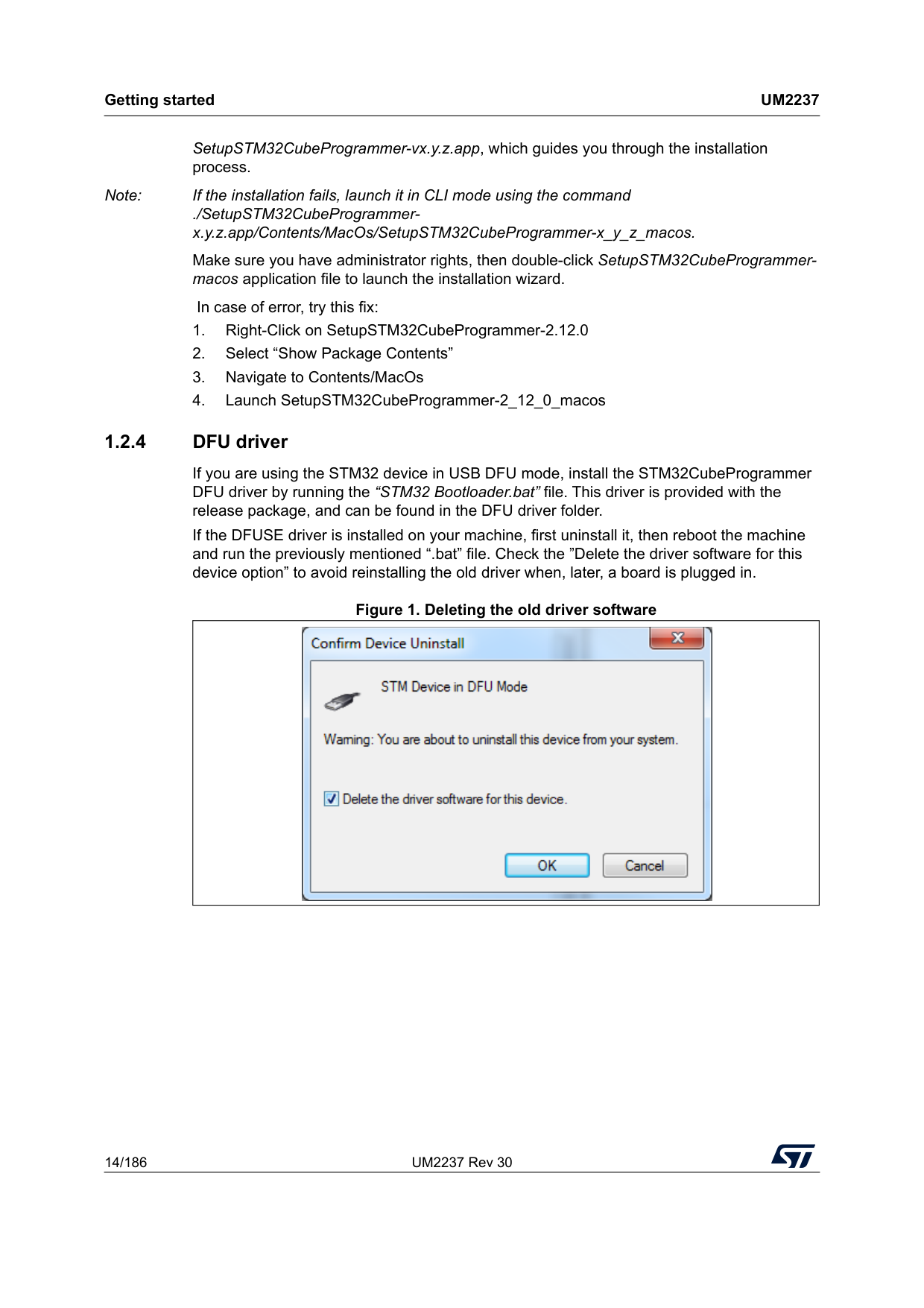
Getting started
Um2237
14/186 UM2237 Rev 30 SetupSTM32CubeProgrammer-vx.y.z.app, which guides you through the installation process. Note: If the installation fails, launch it in CLI mode using the command ./SetupSTM32CubeProgrammer- x.y.z.app/Contents/MacOs/SetupSTM32CubeProgrammer-x_y_z_macos. Make sure you have administrator rights, then double-click SetupSTM32CubeProgrammer- macos application file to launch the installation wizard. In case of error, try this fix: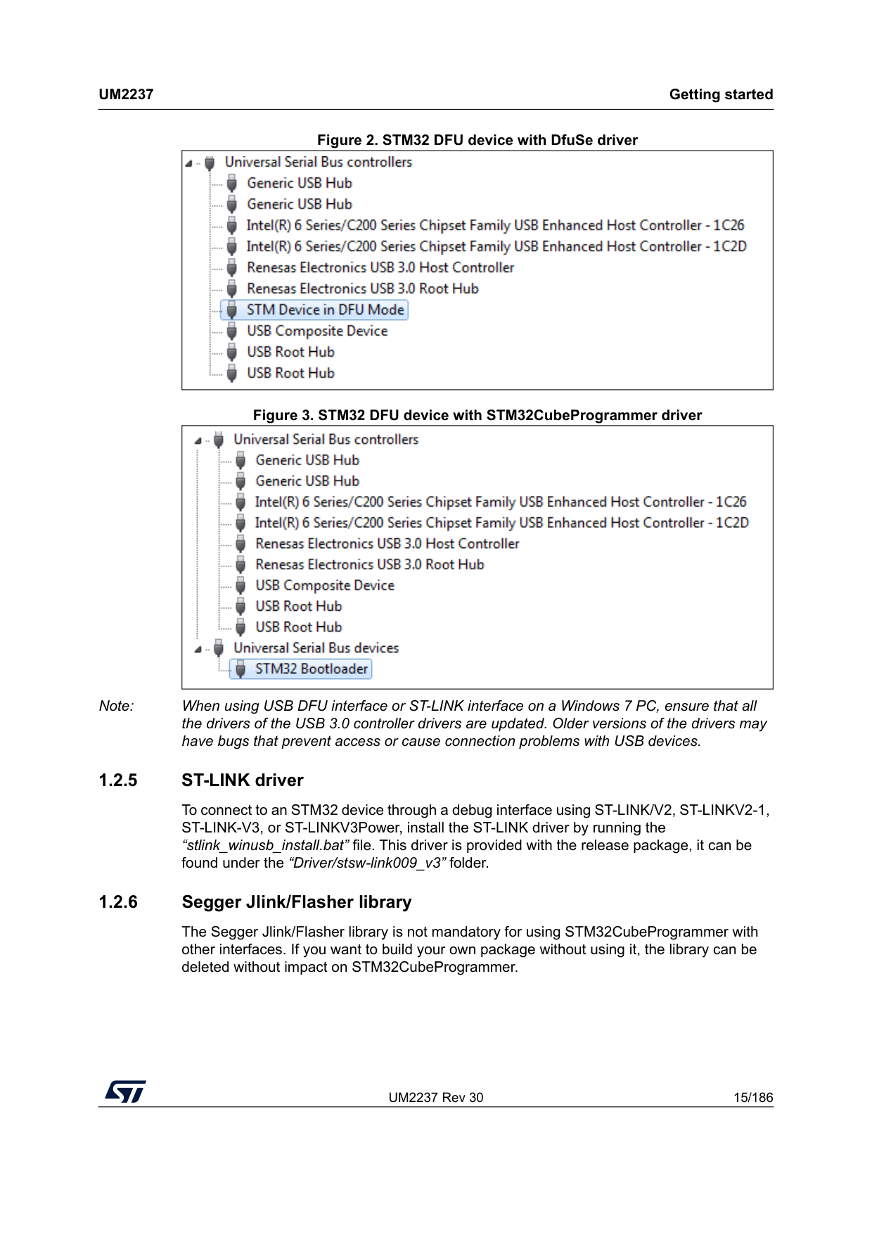
UM2237 Rev 30 15/186
Um2237
Getting started 185 Figure 2. STM32 DFU device with DfuSe driver Figure 3. STM32 DFU device with STM32CubeProgrammer driver Note: When using USB DFU interface or ST-LINK interface on a Windows 7 PC, ensure that all the drivers of the USB 3.0 controller drivers are updated. Older versions of the drivers may have bugs that prevent access or cause connection problems with USB devices. 1.2.5 ST-LINK driver To connect to an STM32 device through a debug interface using ST-LINK/V2, ST-LINKV2-1, ST-LINK-V3, or ST-LINKV3Power, install the ST-LINK driver by running the “stlink_winusb_install.bat” file. This driver is provided with the release package, it can be found under the “Driver/stsw-link009_v3” folder. 1.2.6 Segger Jlink/Flasher library The Segger Jlink/Flasher library is not mandatory for using STM32CubeProgrammer with other interfaces. If you want to build your own package without using it, the library can be deleted without impact on STM32CubeProgrammer.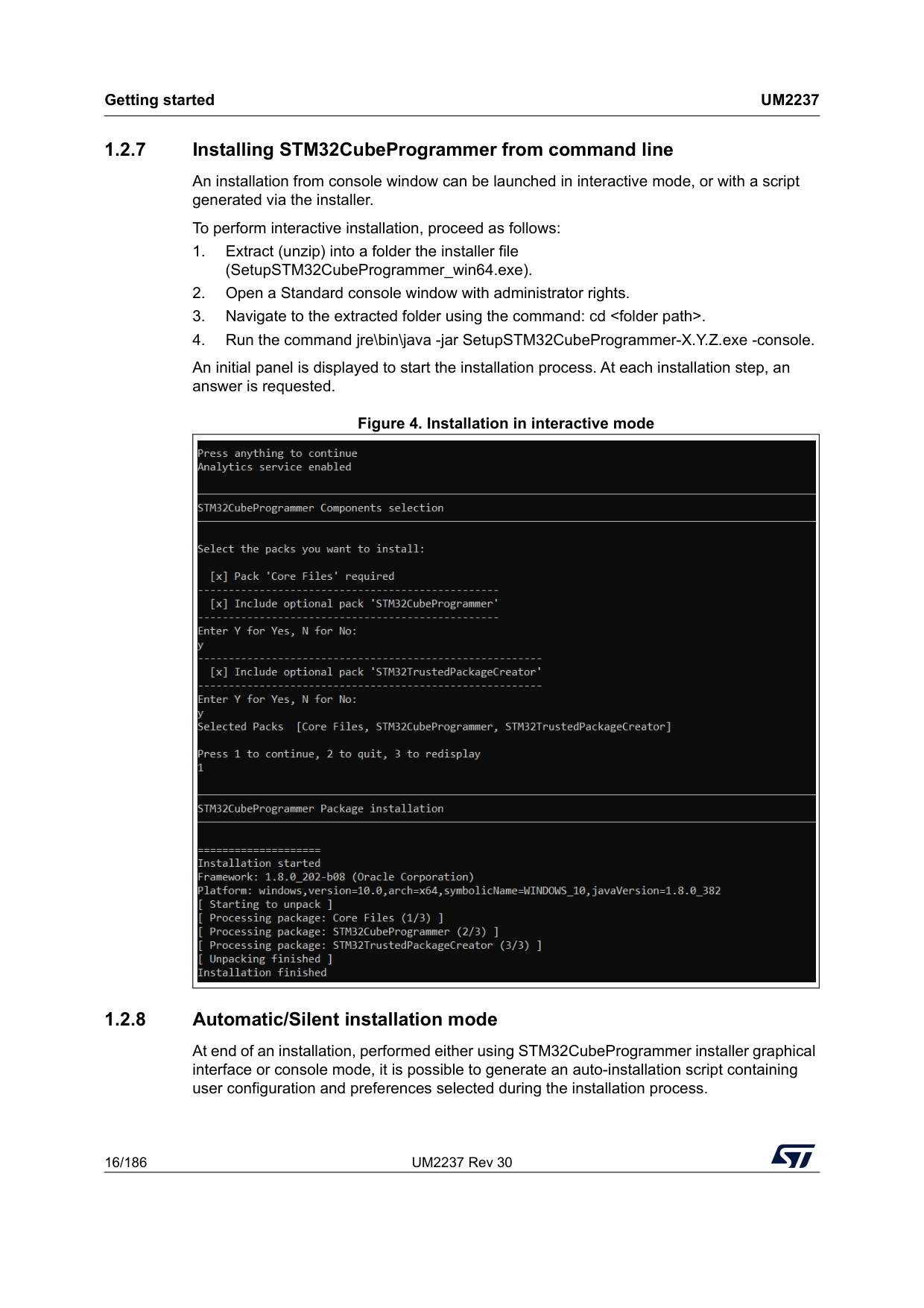
Getting started
Um2237
16/186 UM2237 Rev 30 1.2.7 Installing STM32CubeProgrammer from command line An installation from console window can be launched in interactive mode, or with a script generated via the installer. To perform interactive installation, proceed as follows: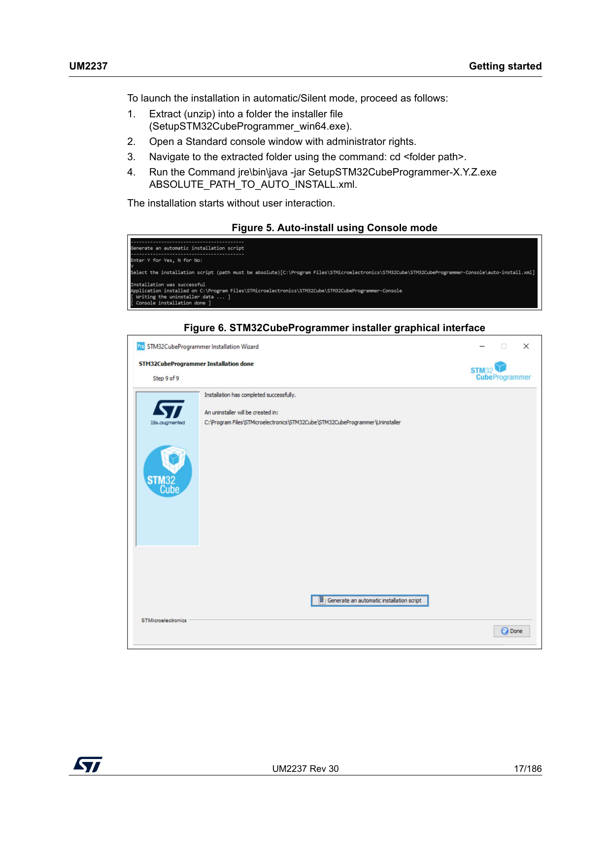
UM2237 Rev 30 17/186
Um2237
Getting started 185 To launch the installation in automatic/Silent mode, proceed as follows: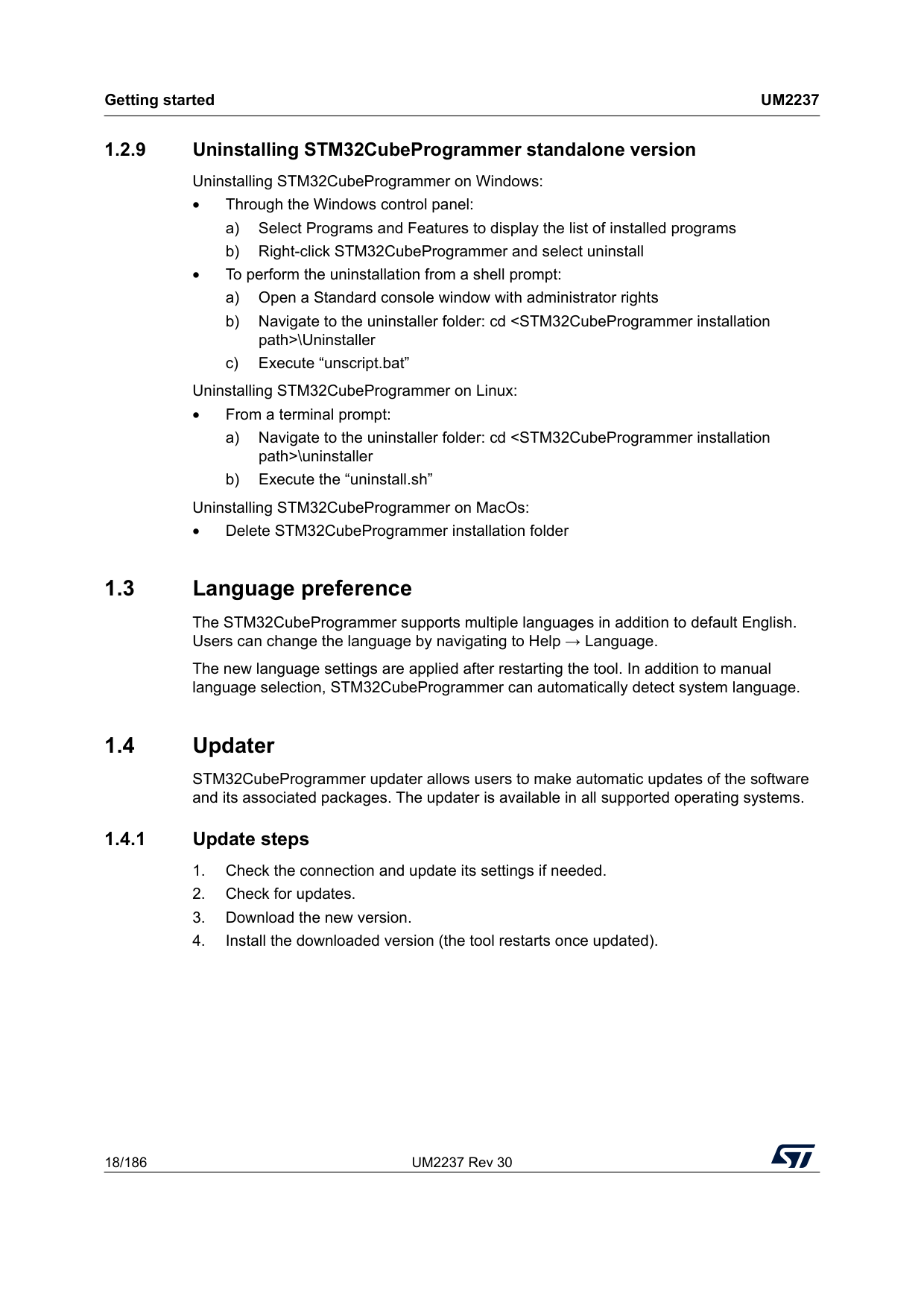
Getting started
Um2237
18/186 UM2237 Rev 30 1.2.9 Uninstalling STM32CubeProgrammer standalone version Uninstalling STM32CubeProgrammer on Windows: • Through the Windows control panel: a) Select Programs and Features to display the list of installed programs b) Right-click STM32CubeProgrammer and select uninstall • To perform the uninstallation from a shell prompt: a) Open a Standard console window with administrator rights b) Navigate to the uninstaller folder: cd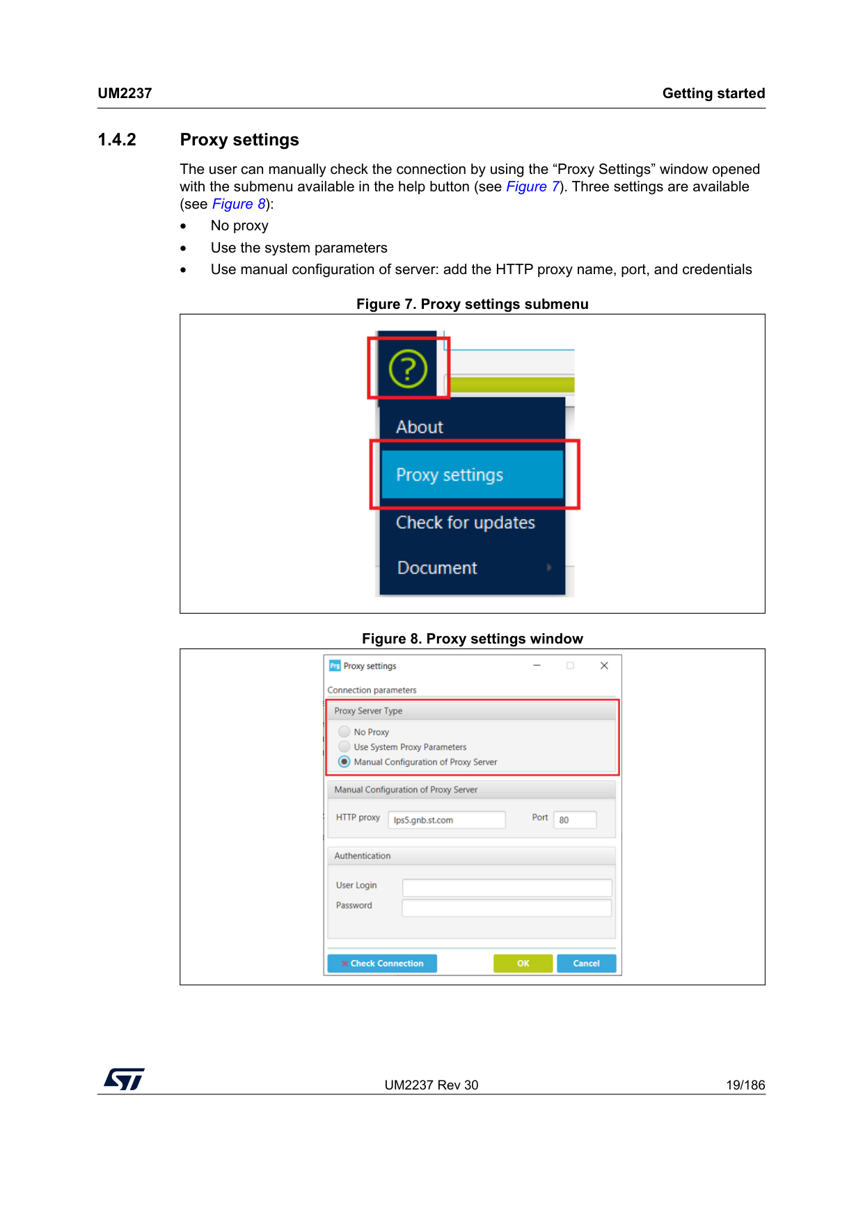
UM2237 Rev 30 19/186
Um2237
Getting started 185 1.4.2 Proxy settings The user can manually check the connection by using the “Proxy Settings” window opened with the submenu available in the help button (see Figure 7). Three settings are available (see Figure 8): • No proxy • Use the system parameters • Use manual configuration of server: add the HTTP proxy name, port, and credentials Figure 7. Proxy settings submenu Figure 8. Proxy settings window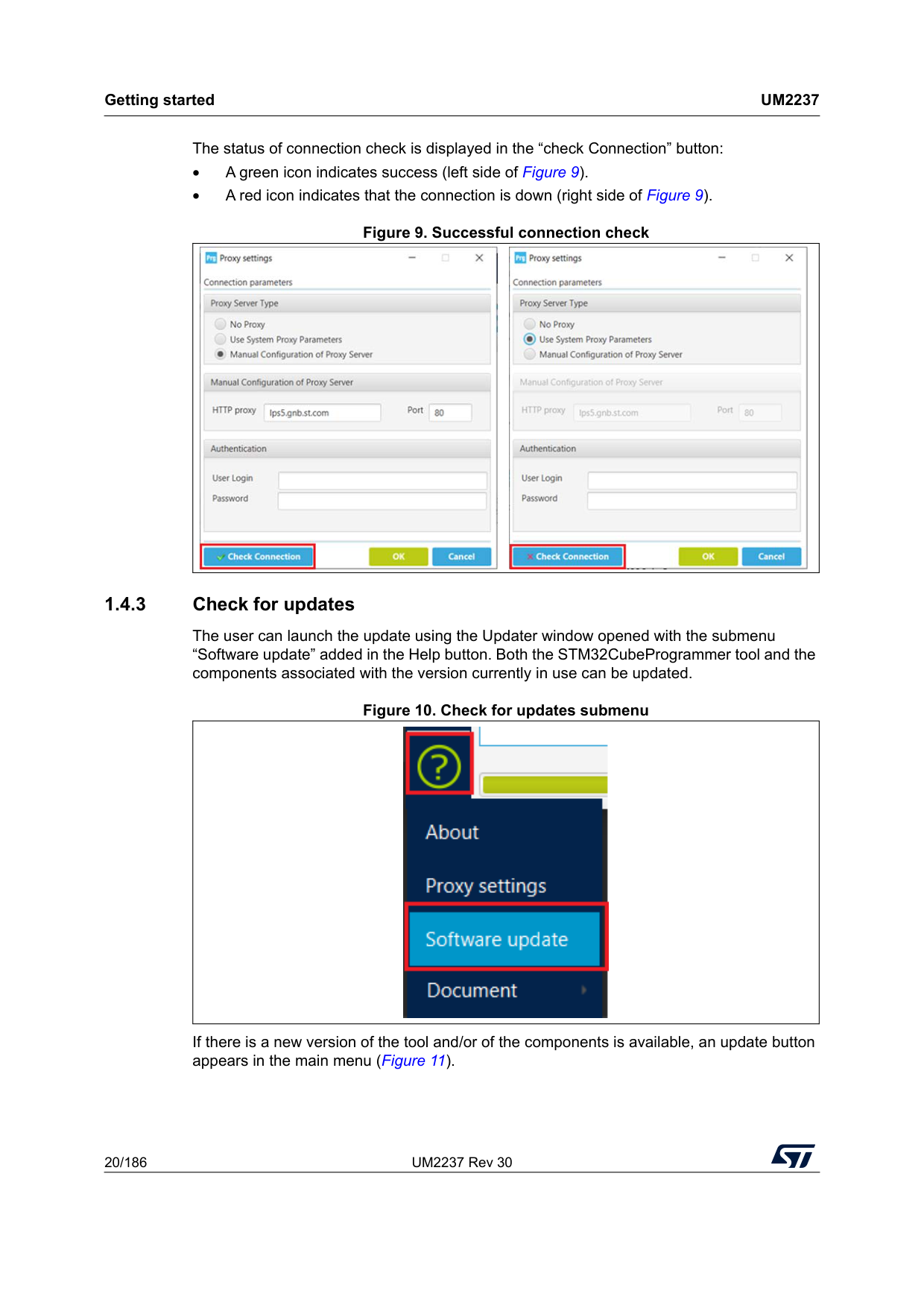
Getting started
Um2237
20/186 UM2237 Rev 30 The status of connection check is displayed in the “check Connection” button: • A green icon indicates success (left side of Figure 9). • A red icon indicates that the connection is down (right side of Figure 9). Figure 9. Successful connection check 1.4.3 Check for updates The user can launch the update using the Updater window opened with the submenu “Software update” added in the Help button. Both the STM32CubeProgrammer tool and the components associated with the version currently in use can be updated. Figure 10. Check for updates submenu If there is a new version of the tool and/or of the components is available, an update button appears in the main menu (Figure 11).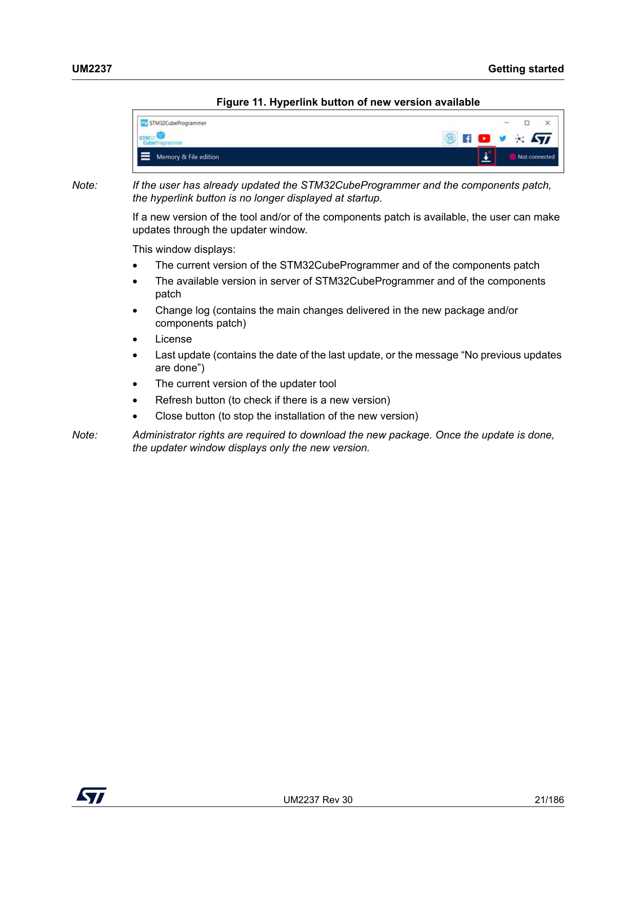
UM2237 Rev 30 21/186
Um2237
Getting started 185 Figure 11. Hyperlink button of new version available Note: If the user has already updated the STM32CubeProgrammer and the components patch, the hyperlink button is no longer displayed at startup. If a new version of the tool and/or of the components patch is available, the user can make updates through the updater window. This window displays: • The current version of the STM32CubeProgrammer and of the components patch • The available version in server of STM32CubeProgrammer and of the components patch • Change log (contains the main changes delivered in the new package and/or components patch) • License • Last update (contains the date of the last update, or the message “No previous updates are done”) • The current version of the updater tool • Refresh button (to check if there is a new version) • Close button (to stop the installation of the new version) Note: Administrator rights are required to download the new package. Once the update is done, the updater window displays only the new version.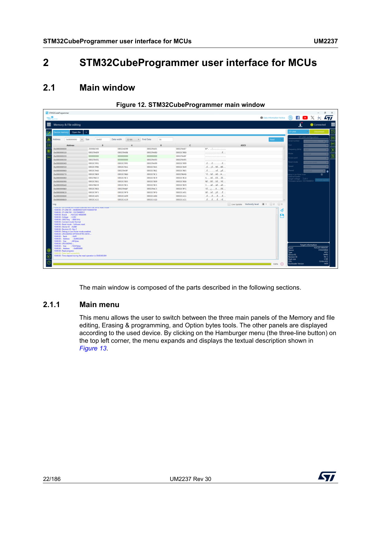
STM32CubeProgrammer user interface for MCUs
Um2237
22/186 UM2237 Rev 30 2 STM32CubeProgrammer user interface for MCUs 2.1 Main window Figure 12. STM32CubeProgrammer main window The main window is composed of the parts described in the following sections. 2.1.1 Main menu This menu allows the user to switch between the three main panels of the Memory and file editing, Erasing & programming, and Option bytes tools. The other panels are displayed according to the used device. By clicking on the Hamburger menu (the three-line button) on the top left corner, the menu expands and displays the textual description shown in Figure 13.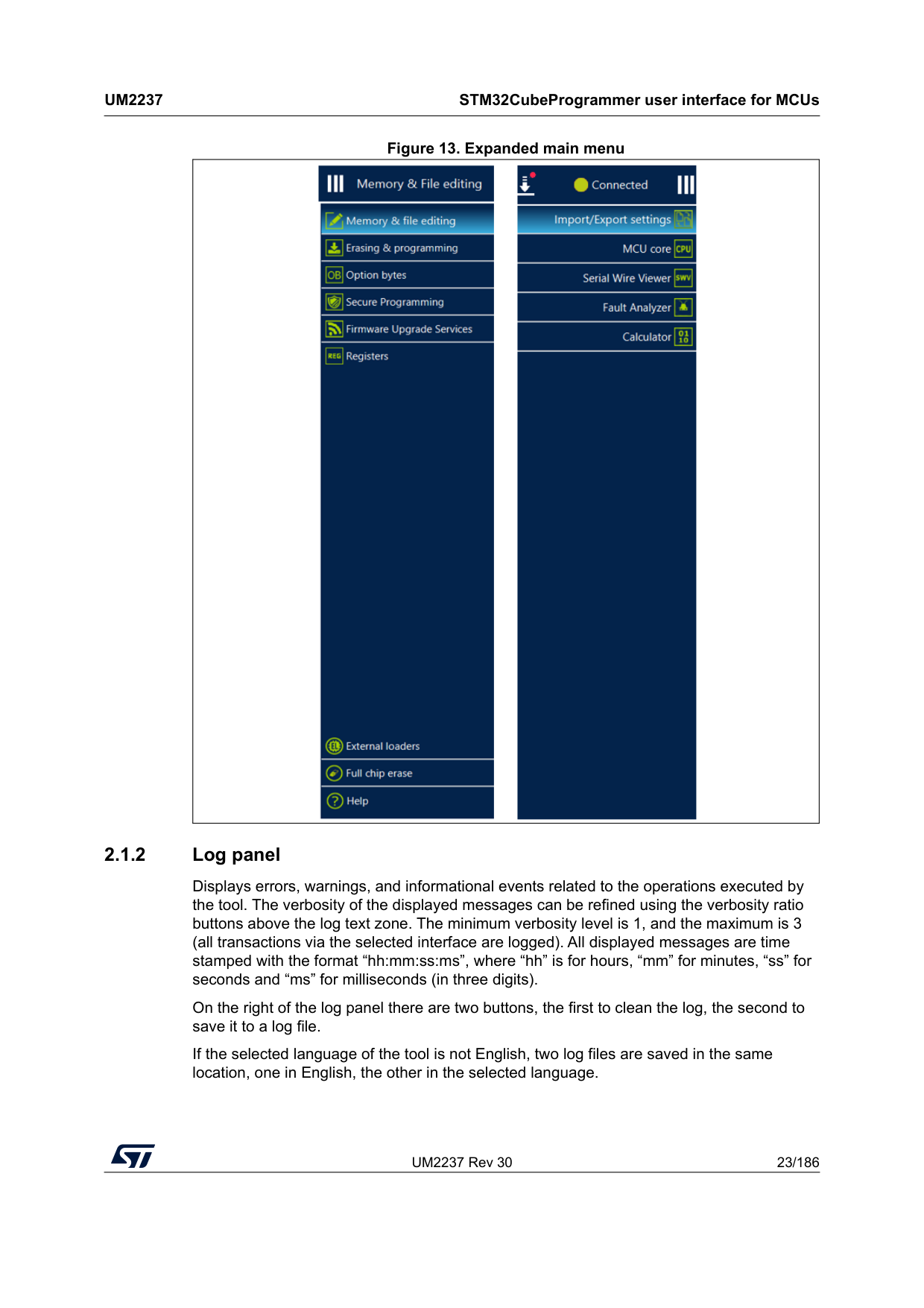
UM2237 Rev 30 23/186
Um2237
STM32CubeProgrammer user interface for MCUs 185 Figure 13. Expanded main menu 2.1.2 Log panel Displays errors, warnings, and informational events related to the operations executed by the tool. The verbosity of the displayed messages can be refined using the verbosity ratio buttons above the log text zone. The minimum verbosity level is 1, and the maximum is 3 (all transactions via the selected interface are logged). All displayed messages are time stamped with the format “hh:mm:ss:ms”, where “hh” is for hours, “mm” for minutes, “ss” for seconds and “ms” for milliseconds (in three digits). On the right of the log panel there are two buttons, the first to clean the log, the second to save it to a log file. If the selected language of the tool is not English, two log files are saved in the same location, one in English, the other in the selected language.
STM32CubeProgrammer user interface for MCUs
Um2237
24/186 UM2237 Rev 30 2.1.3 Progress bar The progress bar visualizes the progress of any operation or transaction done by the tool (for example, Read, Write, Erase). Ongoing operations can be aborted by pressing the “Stop” button in front of the progress bar. 2.1.4 Target configuration panel This is the first panel to look at before connecting to a target. It allows the user to select the target interface (either the debug interface using ST-LINK/J-Link debug probe, or the bootloader interface over UART, USB, SPI, CAN, or I2C). With the refresh button the user can check the available interfaces connected to the PC. If this button is pressed while the ST-LINK/J-Link interface is selected, the tool checks the connected ST-LINK/J-Link probes, and lists them in the Serial numbers combo box. If the UART interface is selected, it checks the available communication ports of the PC, and lists them in the Port combo box. If the USB interface is selected, it checks the USB devices in DFU mode connected to the PC, and lists them in the Port combo box. Each interface has its own settings, to set before connection.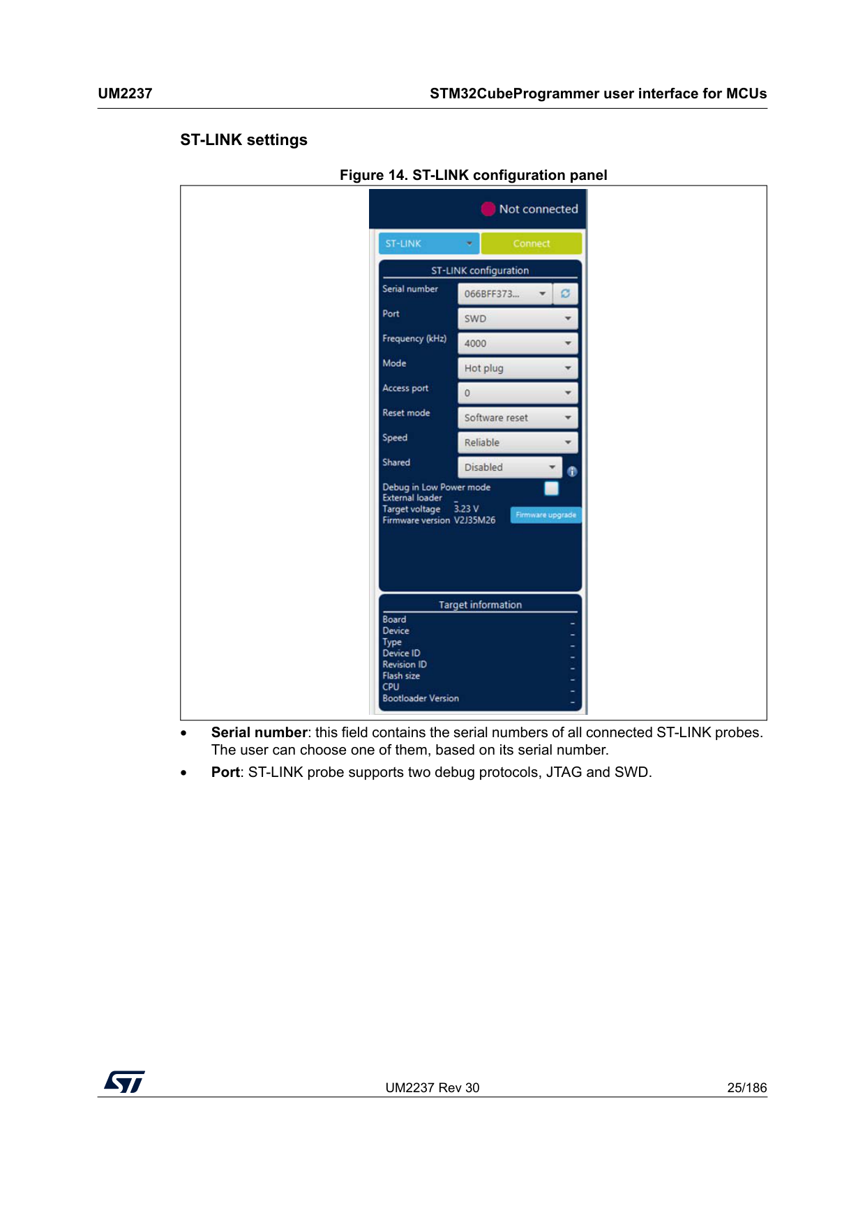
UM2237 Rev 30 25/186
Um2237
STM32CubeProgrammer user interface for MCUs 185 ST-LINK settings Figure 14. ST-LINK configuration panel • Serial number: this field contains the serial numbers of all connected ST-LINK probes. The user can choose one of them, based on its serial number. • Port: ST-LINK probe supports two debug protocols, JTAG and SWD.
STM32CubeProgrammer user interface for MCUs
Um2237
26/186 UM2237 Rev 30 Note: JTAG is not available on all embedded ST-LINK in the STM32 Nucleo or Discovery boards. • Frequency: the JTAG or SWD clock frequency • Access port: selects the access port to connect to. Most of the STM32 devices have only one access port, which is Access port 0. • Mode: – Normal: with “Normal” connection mode, the target is reset then halted. The type of reset is selected using the “Reset Mode” option. – Connect under reset: this mode enables connection to the target using a reset vector catch before executing any instructions. This is useful in many cases, for example when the target contains a code that disables the JTAG/SWD pins. – Hot plug: enables connection to the target without a halt or reset. This is useful for updating the RAM addresses or the IP registers while the application is running. – Power down: used to put the target in debug mode, even if the application has not started since the target power-up. The hardware reset signal must be connected between ST-LINK and the target. This feature can be not fully effective on some boards (MB1360, MB1319, MB1361, MB1355) with STMPS2141 power switch. – hwRstPulse: the tool generates a reset pulse, and then connects to the target. This connection mode does not prevent application launch before connection. It is used in some devices where under mode is not available (such as STM32WB0x and STM32WL33) • Reset mode: – Software system reset: resets all STM32 components except the Debug via the Cortex-M application interrupt and reset control register (AIRCR). – Hardware reset: resets the STM32 device via the nRST pin. The RESET pin of the JTAG connector (pin 15) must be connected to the device reset pin. – Core reset: resets only the Cortex-M via the AIRCR(a). • Speed (Cortex-M33 only): – Reliable: allows the user to connect with a slow mode. – Fast: allows the user to connect with a fast mode. • Shared: enables shared mode allowing connection of two or more instances of STM32CubeProgrammer or other debugger to the same ST-LINK probe. • Debug in low-power mode (STM32U5/WB/L4 series only): sets the bits in DBGMCU_CR to 1. • External loader: displays the name of the external memory loader selected in the “External loaders” panel accessible from the main menu (Hamburger menu). • Target voltage: target voltage is measured and displayed. • Firmware version: displays the ST-LINK firmware version. The firmware upgrade button allows you to upgrade the ST-LINK firmware. a. Core reset does not exist for Cortex-M33, Cortex-M55 and Cortex-M85.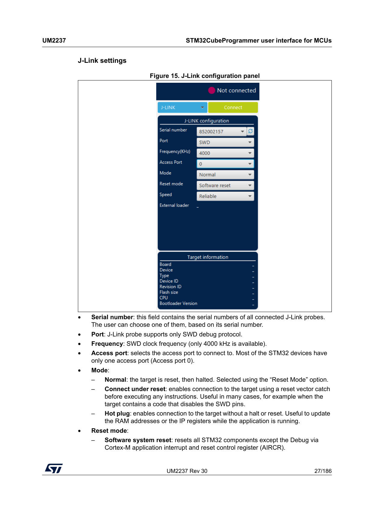
UM2237 Rev 30 27/186
Um2237
STM32CubeProgrammer user interface for MCUs 185 J-Link settings Figure 15. J-Link configuration panel • Serial number: this field contains the serial numbers of all connected J-Link probes. The user can choose one of them, based on its serial number. • Port: J-Link probe supports only SWD debug protocol. • Frequency: SWD clock frequency (only 4000 kHz is available). • Access port: selects the access port to connect to. Most of the STM32 devices have only one access port (Access port 0). • Mode: – Normal: the target is reset, then halted. Selected using the “Reset Mode” option. – Connect under reset: enables connection to the target using a reset vector catch before executing any instructions. Useful in many cases, for example when the target contains a code that disables the SWD pins. – Hot plug: enables connection to the target without a halt or reset. Useful to update the RAM addresses or the IP registers while the application is running. • Reset mode: – Software system reset: resets all STM32 components except the Debug via Cortex-M application interrupt and reset control register (AIRCR).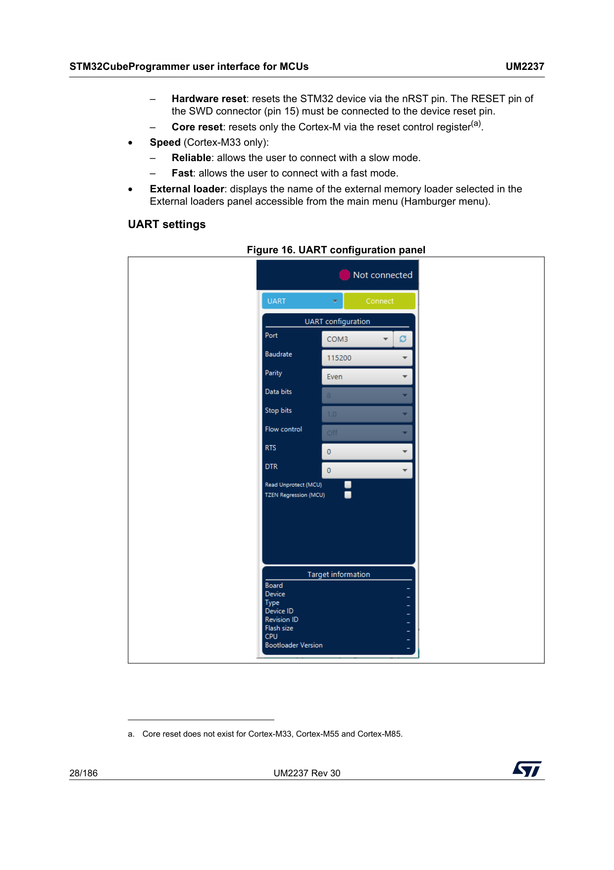
STM32CubeProgrammer user interface for MCUs
Um2237
28/186 UM2237 Rev 30 – Hardware reset: resets the STM32 device via the nRST pin. The RESET pin of the SWD connector (pin 15) must be connected to the device reset pin. – Core reset: resets only the Cortex-M via the reset control register(a). • Speed (Cortex-M33 only): – Reliable: allows the user to connect with a slow mode. – Fast: allows the user to connect with a fast mode. • External loader: displays the name of the external memory loader selected in the External loaders panel accessible from the main menu (Hamburger menu). UART settings Figure 16. UART configuration panel a. Core reset does not exist for Cortex-M33, Cortex-M55 and Cortex-M85.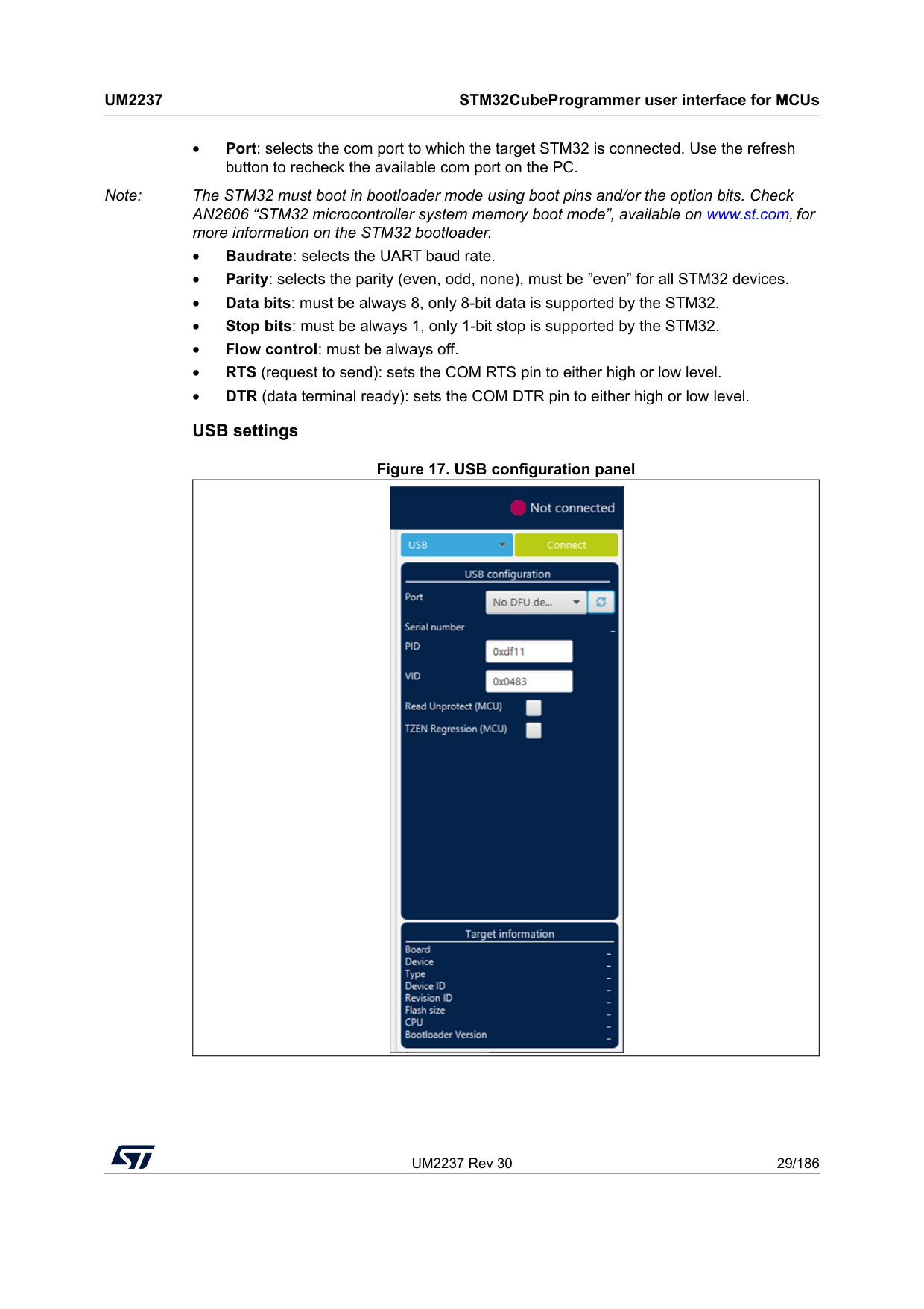
UM2237 Rev 30 29/186
Um2237
STM32CubeProgrammer user interface for MCUs 185 • Port: selects the com port to which the target STM32 is connected. Use the refresh button to recheck the available com port on the PC. Note: The STM32 must boot in bootloader mode using boot pins and/or the option bits. Check AN2606 “STM32 microcontroller system memory boot mode”, available on www.st.com, for more information on the STM32 bootloader. • Baudrate: selects the UART baud rate. • Parity: selects the parity (even, odd, none), must be ”even” for all STM32 devices. • Data bits: must be always 8, only 8-bit data is supported by the STM32. • Stop bits: must be always 1, only 1-bit stop is supported by the STM32. • Flow control: must be always off. • RTS (request to send): sets the COM RTS pin to either high or low level. • DTR (data terminal ready): sets the COM DTR pin to either high or low level. USB settings Figure 17. USB configuration panel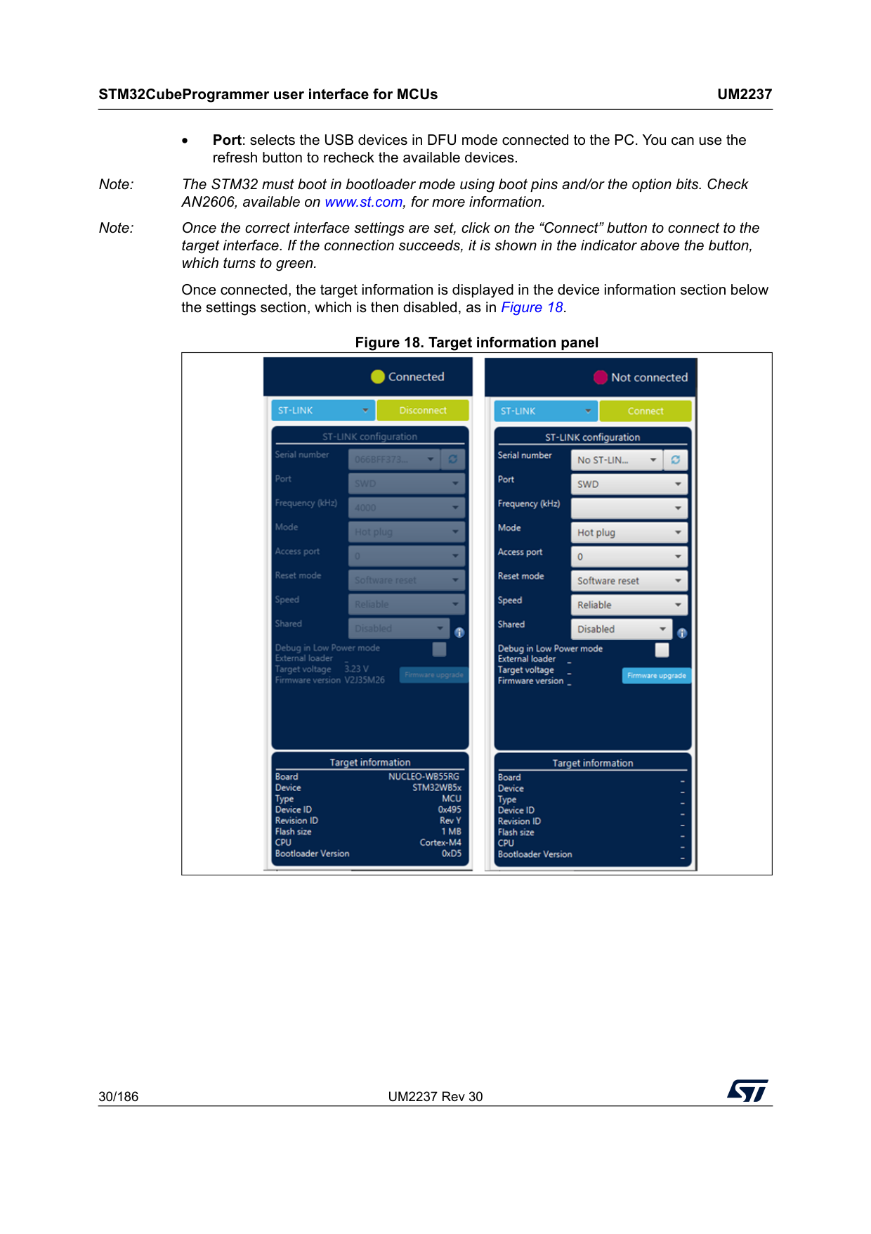
STM32CubeProgrammer user interface for MCUs
Um2237
30/186 UM2237 Rev 30 • Port: selects the USB devices in DFU mode connected to the PC. You can use the refresh button to recheck the available devices. Note: The STM32 must boot in bootloader mode using boot pins and/or the option bits. Check AN2606, available on www.st.com, for more information. Note: Once the correct interface settings are set, click on the “Connect” button to connect to the target interface. If the connection succeeds, it is shown in the indicator above the button, which turns to green. Once connected, the target information is displayed in the device information section below the settings section, which is then disabled, as in Figure 18. Figure 18. Target information panel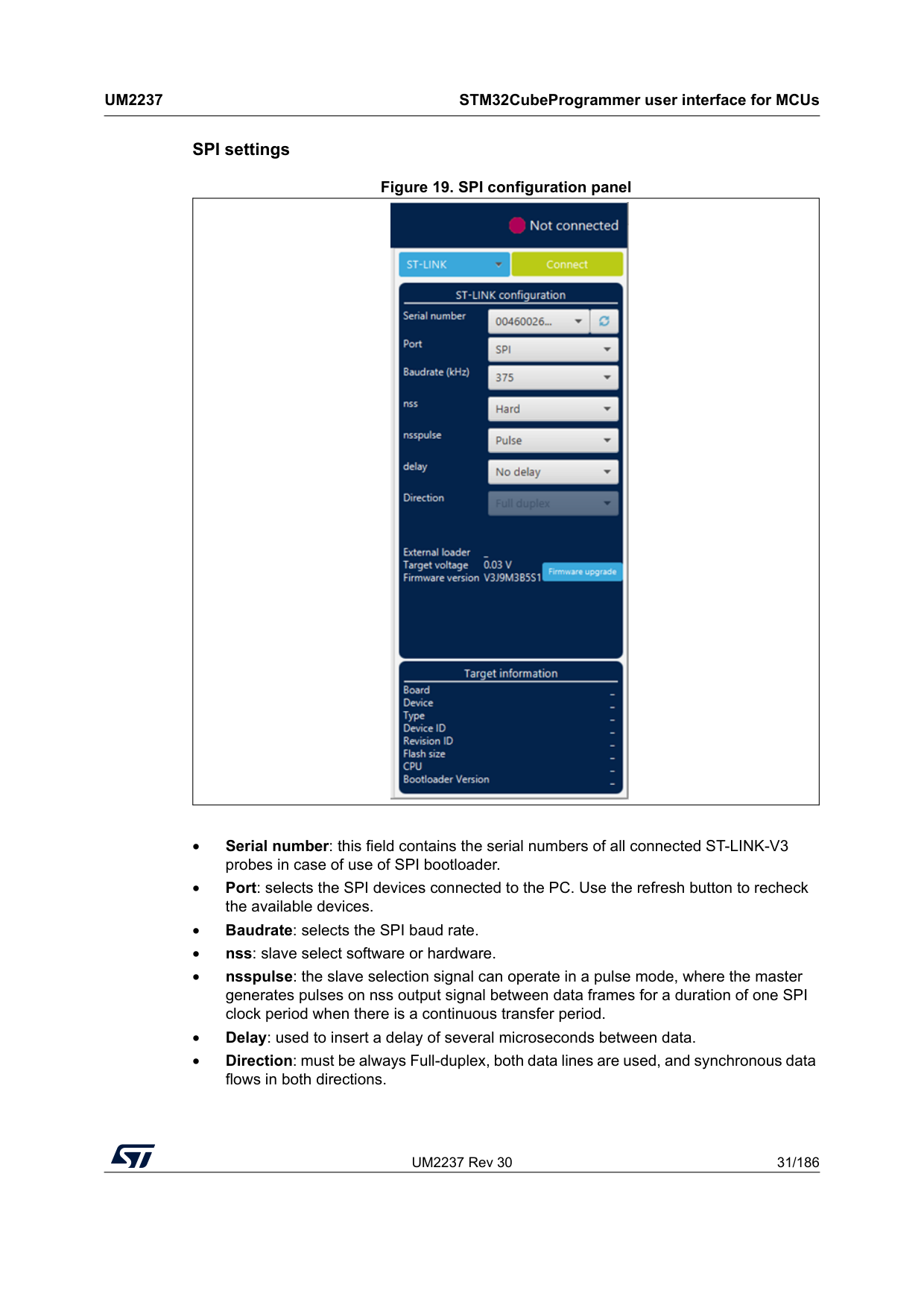
UM2237 Rev 30 31/186
Um2237
STM32CubeProgrammer user interface for MCUs 185 SPI settings Figure 19. SPI configuration panel • Serial number: this field contains the serial numbers of all connected ST-LINK-V3 probes in case of use of SPI bootloader. • Port: selects the SPI devices connected to the PC. Use the refresh button to recheck the available devices. • Baudrate: selects the SPI baud rate. • nss: slave select software or hardware. • nsspulse: the slave selection signal can operate in a pulse mode, where the master generates pulses on nss output signal between data frames for a duration of one SPI clock period when there is a continuous transfer period. • Delay: used to insert a delay of several microseconds between data. • Direction: must be always Full-duplex, both data lines are used, and synchronous data flows in both directions.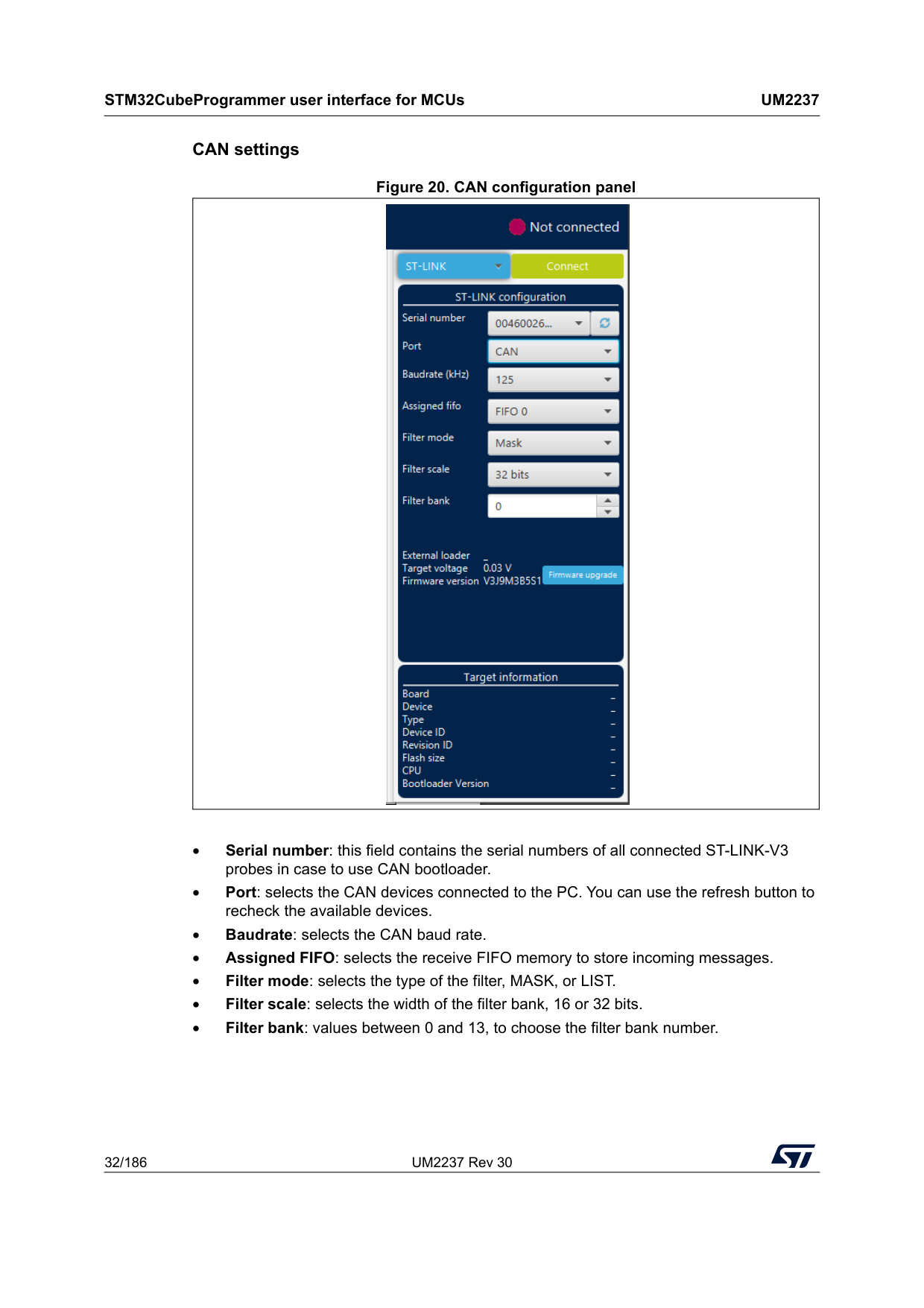
STM32CubeProgrammer user interface for MCUs
Um2237
32/186 UM2237 Rev 30 CAN settings Figure 20. CAN configuration panel • Serial number: this field contains the serial numbers of all connected ST-LINK-V3 probes in case to use CAN bootloader. • Port: selects the CAN devices connected to the PC. You can use the refresh button to recheck the available devices. • Baudrate: selects the CAN baud rate. • Assigned FIFO: selects the receive FIFO memory to store incoming messages. • Filter mode: selects the type of the filter, MASK, or LIST. • Filter scale: selects the width of the filter bank, 16 or 32 bits. • Filter bank: values between 0 and 13, to choose the filter bank number.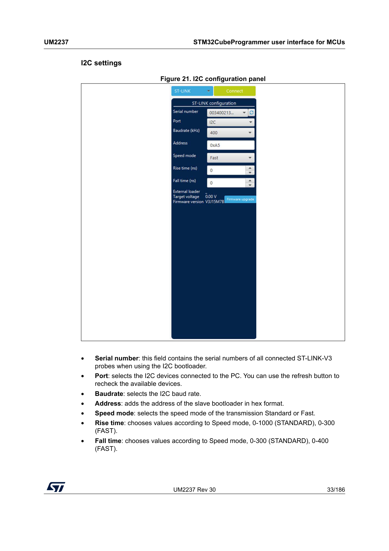
UM2237 Rev 30 33/186
Um2237
STM32CubeProgrammer user interface for MCUs 185 I2C settings Figure 21. I2C configuration panel • Serial number: this field contains the serial numbers of all connected ST-LINK-V3 probes when using the I2C bootloader. • Port: selects the I2C devices connected to the PC. You can use the refresh button to recheck the available devices. • Baudrate: selects the I2C baud rate. • Address: adds the address of the slave bootloader in hex format. • Speed mode: selects the speed mode of the transmission Standard or Fast. • Rise time: chooses values according to Speed mode, 0-1000 (STANDARD), 0-300(Fast).
• Fall time: chooses values according to Speed mode, 0-300 (STANDARD), 0-400(Fast).
STM32CubeProgrammer user interface for MCUs
Um2237
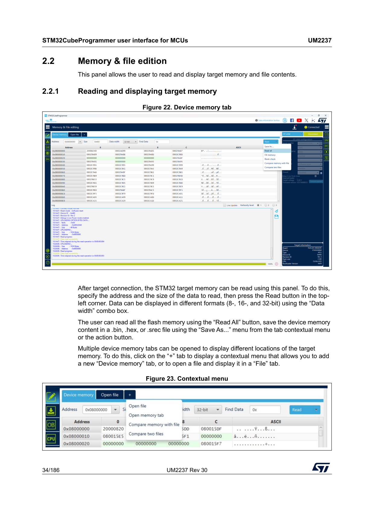
34/186 UM2237 Rev 30 2.2 Memory & file edition This panel allows the user to read and display target memory and file contents. 2.2.1 Reading and displaying target memory Figure 22. Device memory tab After target connection, the STM32 target memory can be read using this panel. To do this, specify the address and the size of the data to read, then press the Read button in the top- left corner. Data can be displayed in different formats (8-, 16-, and 32-bit) using the “Data width” combo box. The user can read all the flash memory using the “Read All” button, save the device memory content in a .bin, .hex, or .srec file using the “Save As...” menu from the tab contextual menu or the action button. Multiple device memory tabs can be opened to display different locations of the target memory. To do this, click on the “+” tab to display a contextual menu that allows you to add a new “Device memory” tab, or to open a file and display it in a “File” tab. Figure 23. Contextual menu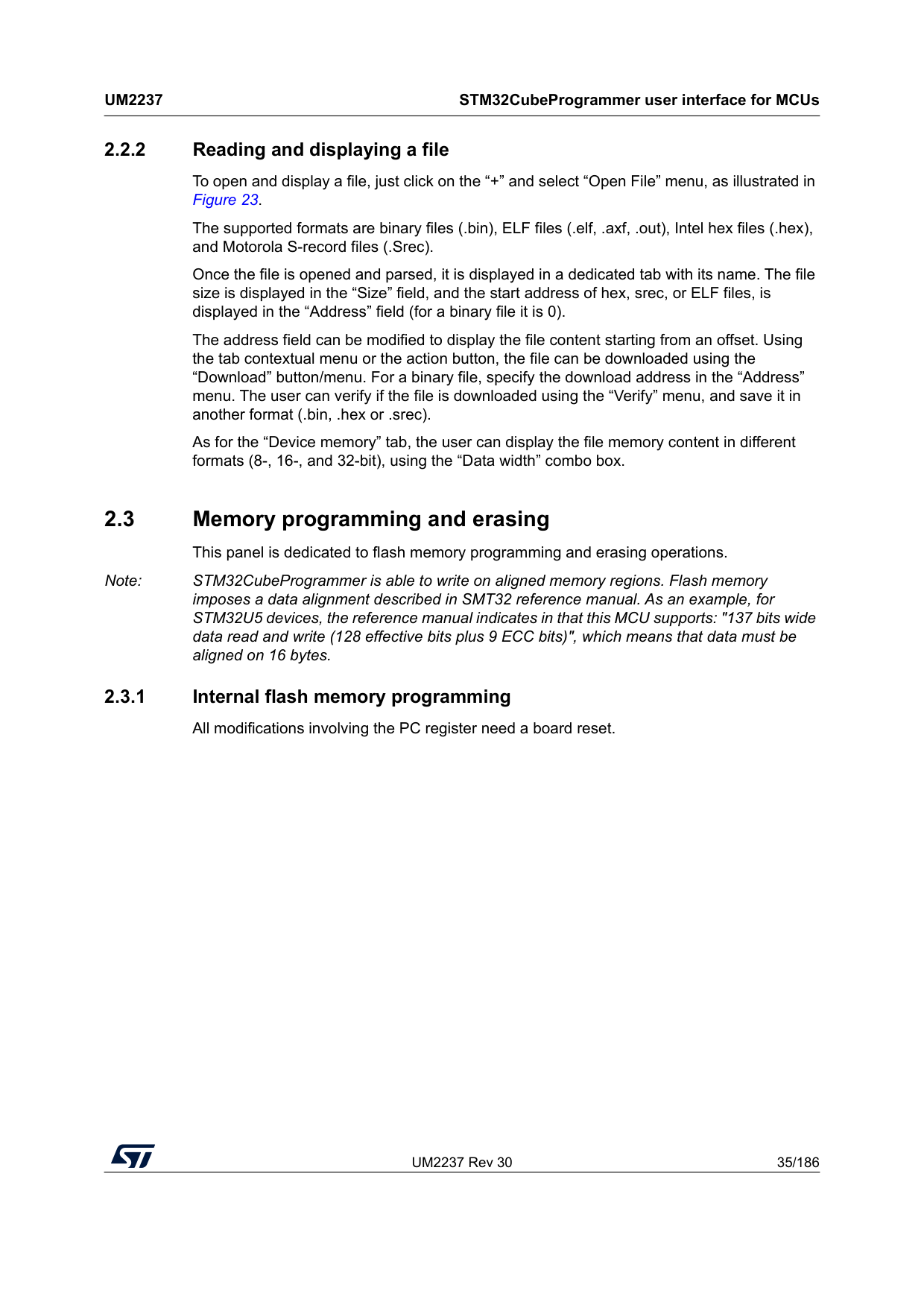
UM2237 Rev 30 35/186
Um2237
STM32CubeProgrammer user interface for MCUs 185 2.2.2 Reading and displaying a file To open and display a file, just click on the “+” and select “Open File” menu, as illustrated in Figure 23. The supported formats are binary files (.bin), ELF files (.elf, .axf, .out), Intel hex files (.hex), and Motorola S-record files (.Srec). Once the file is opened and parsed, it is displayed in a dedicated tab with its name. The file size is displayed in the “Size” field, and the start address of hex, srec, or ELF files, is displayed in the “Address” field (for a binary file it is 0). The address field can be modified to display the file content starting from an offset. Using the tab contextual menu or the action button, the file can be downloaded using the “Download” button/menu. For a binary file, specify the download address in the “Address” menu. The user can verify if the file is downloaded using the “Verify” menu, and save it in another format (.bin, .hex or .srec). As for the “Device memory” tab, the user can display the file memory content in different formats (8-, 16-, and 32-bit), using the “Data width” combo box. 2.3 Memory programming and erasing This panel is dedicated to flash memory programming and erasing operations. Note: STM32CubeProgrammer is able to write on aligned memory regions. Flash memory imposes a data alignment described in SMT32 reference manual. As an example, for STM32U5 devices, the reference manual indicates in that this MCU supports: "137 bits wide data read and write (128 effective bits plus 9 ECC bits)", which means that data must be aligned on 16 bytes. 2.3.1 Internal flash memory programming All modifications involving the PC register need a board reset.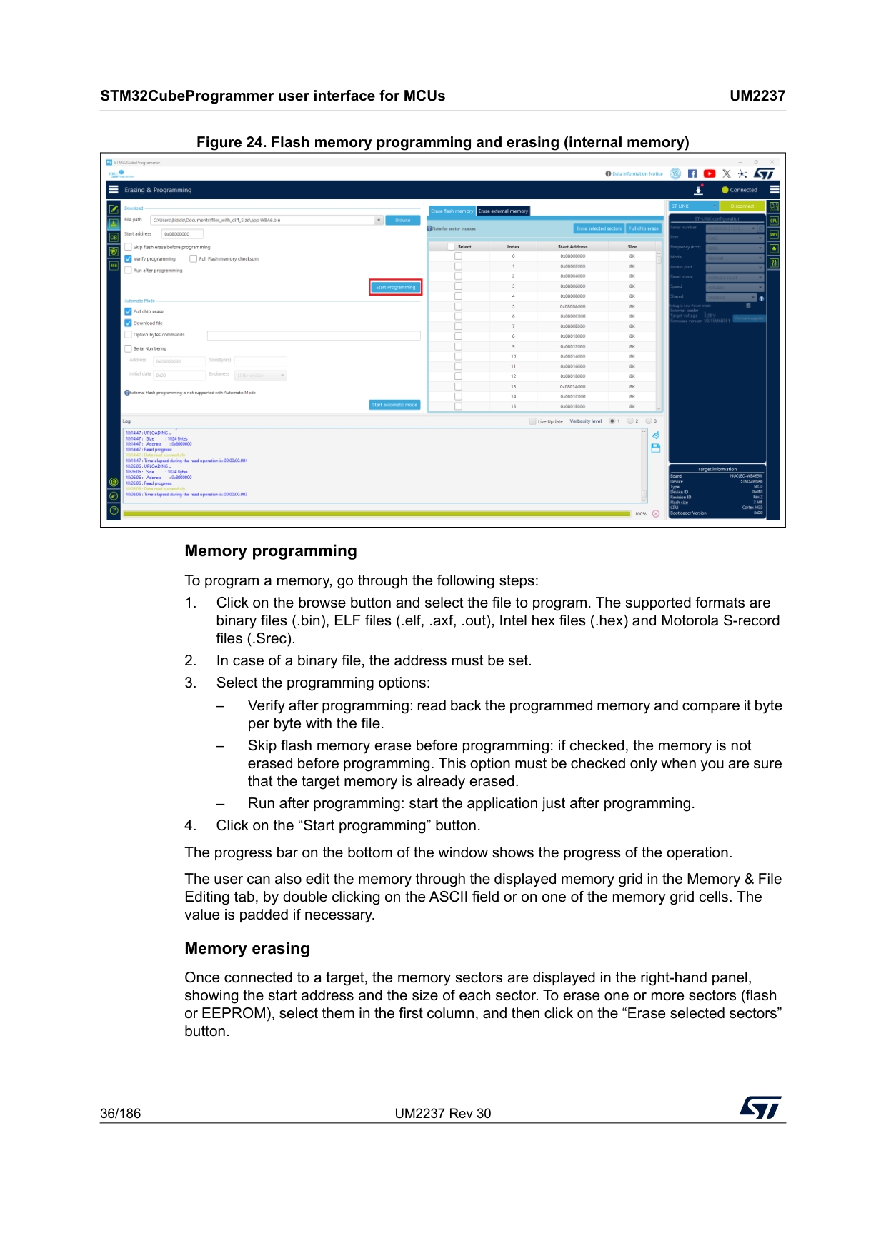
STM32CubeProgrammer user interface for MCUs
Um2237
36/186 UM2237 Rev 30 Figure 24. Flash memory programming and erasing (internal memory) Memory programming To program a memory, go through the following steps: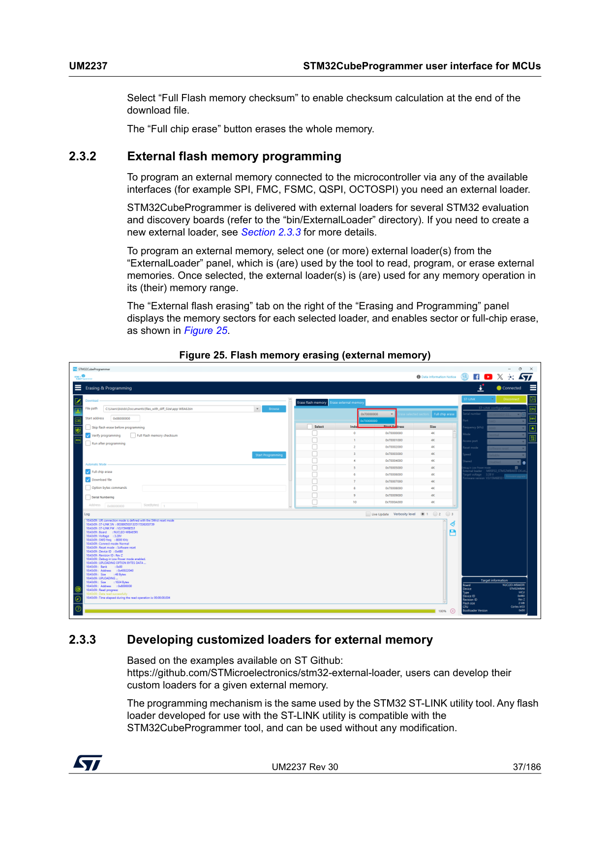
UM2237 Rev 30 37/186
Um2237
STM32CubeProgrammer user interface for MCUs 185 Select “Full Flash memory checksum” to enable checksum calculation at the end of the download file. The “Full chip erase” button erases the whole memory. 2.3.2 External flash memory programming To program an external memory connected to the microcontroller via any of the available interfaces (for example SPI, FMC, FSMC, QSPI, OCTOSPI) you need an external loader. STM32CubeProgrammer is delivered with external loaders for several STM32 evaluation and discovery boards (refer to the “bin/ExternalLoader” directory). If you need to create a new external loader, see Section 2.3.3 for more details. To program an external memory, select one (or more) external loader(s) from the “ExternalLoader” panel, which is (are) used by the tool to read, program, or erase external memories. Once selected, the external loader(s) is (are) used for any memory operation in its (their) memory range. The “External flash erasing” tab on the right of the “Erasing and Programming” panel displays the memory sectors for each selected loader, and enables sector or full-chip erase, as shown in Figure 25. Figure 25. Flash memory erasing (external memory) 2.3.3 Developing customized loaders for external memory Based on the examples available on ST Github: https://github.com/STMicroelectronics/stm32-external-loader, users can develop their custom loaders for a given external memory. The programming mechanism is the same used by the STM32 ST-LINK utility tool. Any flash loader developed for use with the ST-LINK utility is compatible with the STM32CubeProgrammer tool, and can be used without any modification.
STM32CubeProgrammer user interface for MCUs
Um2237
38/186 UM2237 Rev 30 To create a new external memory loader, follow the steps below:
UM2237 Rev 30 39/186
Um2237
STM32CubeProgrammer user interface for MCUs 185 int Read (uint32_t Address, uint32_t Size, uint16_t* buffer) Where “Address” = start address of read operation, “Size” is the size of the read operation and “buffer” is the pointer to data read. Note: For Quad-/Octo-SPI memories, the memory mapped mode can be defined in the Init function; in that case, the Read function is useless, as data can be read directly from JTAG/SWD interface. • Verify function The Verify function is called when selecting the “verify while programming” mode. This function checks if the programmed memory corresponds to the buffer defined in the RAM. It returns an uint64 defined as follows: Return value = ((checksum<<32) + AddressFirstError) where AddressFirstError is the address of the first mismatch, and checksum is the checksum value of the programmed buffer. uint64_t Verify (uint32_t FlashAddr, uint32_t RAMBufferAddr, uint32_t Size) • MassErase function The MassErase function erases the full memory. Returns 1 if success, and 0 if failure. int MassErase (void) • A checksum function All the functions described return 1 in case of a successful operation, 0 in case of a fail. Dev_Inf.c file The StorageInfo structure defined in this file provides information on the external memory. An example of the type of information defined by this structure is given below: #if defined (__ICCARM__) __root struct StorageInfo const StorageInfo = { #else struct StorageInfo const StorageInfo = { #endif ”External_Loader_Name”, // Device Name + version number MCU_FLASH, // Device Type 0x08000000, // Device Start Address 0x00100000, // Device Size in Bytes (1MBytes/8Mbits) 0x00004000, // Programming Page Size 16KBytes 0xFF, // Initial Content of Erased Memory // Specify Size and Address of Sectors (view example below) 0x00000004, 0x00004000, // Sector Num : 4, Sector Size: 16KBytes 0x00000001, 0x00010000, // Sector Num : 1, Sector Size: 64KBytes 0x00000007, 0x00020000, // Sector Num : 7, Sector Size: 128KBytes 0x00000000, 0x00000000, };
STM32CubeProgrammer user interface for MCUs
Um2237
40/186 UM2237 Rev 30 2.3.4 External memory programming with bootloader interfaces on GUI This feature is supported by STM32H7Rx/7Sx products. Go through the sequence outlined below to successfully program the external memory using bootloader interfaces: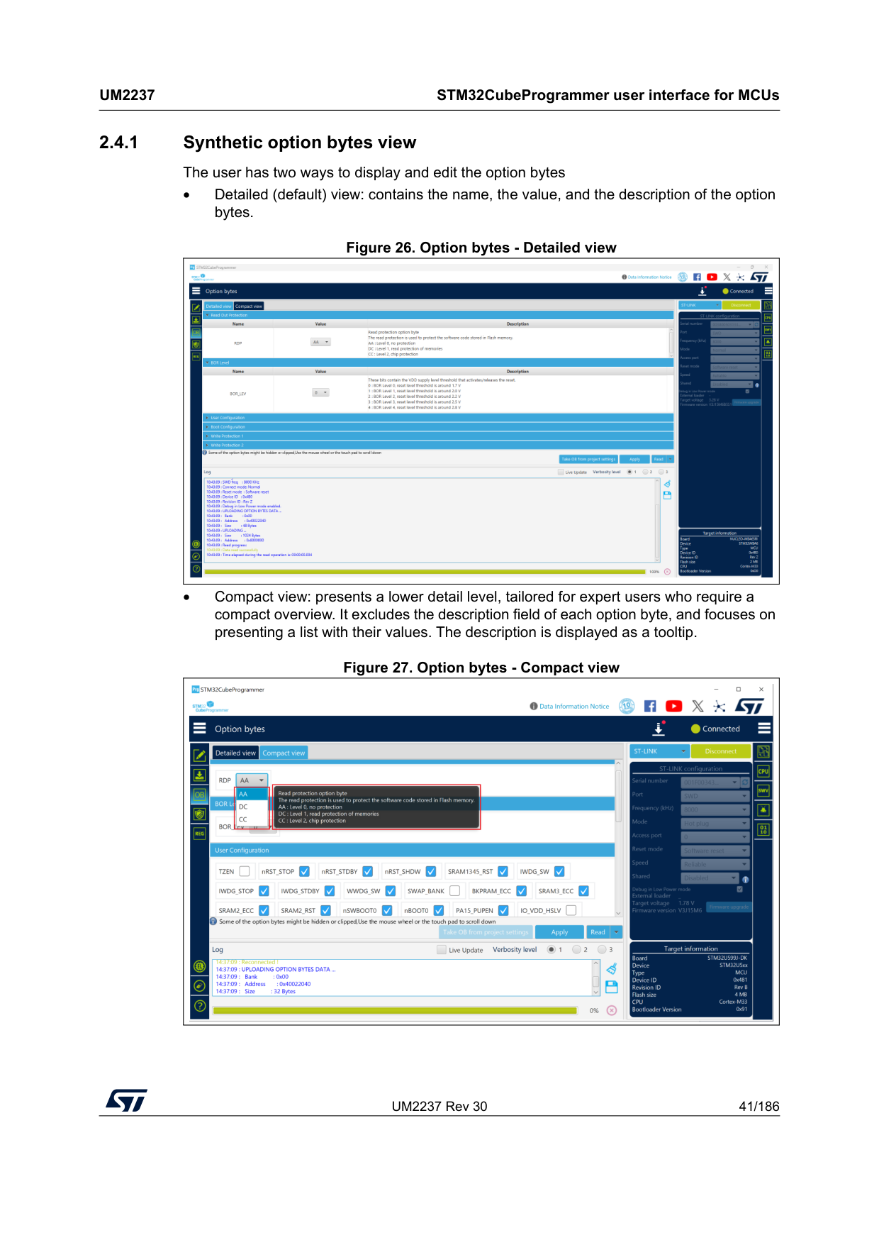
UM2237 Rev 30 41/186
Um2237
STM32CubeProgrammer user interface for MCUs 185 2.4.1 Synthetic option bytes view The user has two ways to display and edit the option bytes • Detailed (default) view: contains the name, the value, and the description of the option bytes. Figure 26. Option bytes - Detailed view • Compact view: presents a lower detail level, tailored for expert users who require a compact overview. It excludes the description field of each option byte, and focuses on presenting a list with their values. The description is displayed as a tooltip. Figure 27. Option bytes - Compact view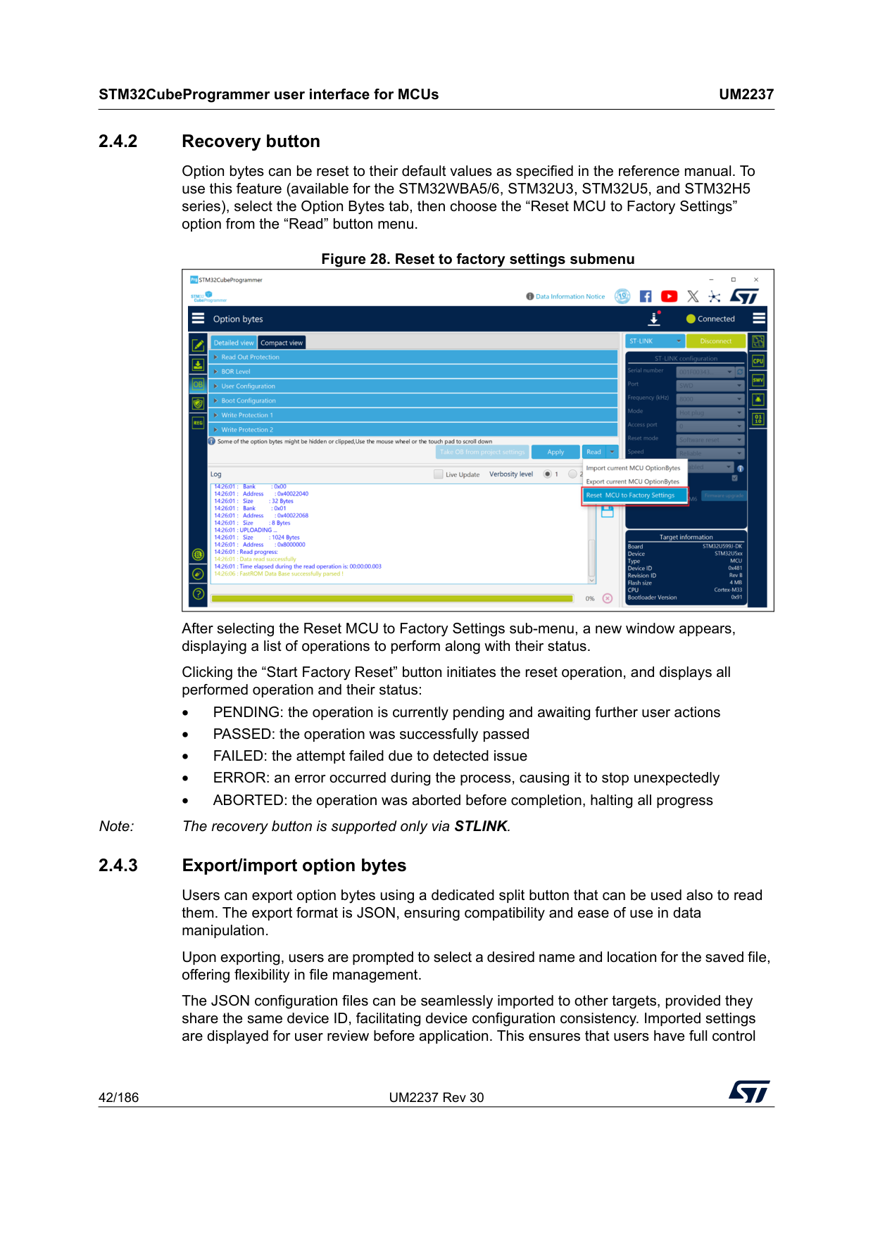
STM32CubeProgrammer user interface for MCUs
Um2237
42/186 UM2237 Rev 30 2.4.2 Recovery button Option bytes can be reset to their default values as specified in the reference manual. To use this feature (available for the STM32WBA5/6, STM32U3, STM32U5, and STM32H5 series), select the Option Bytes tab, then choose the “Reset MCU to Factory Settings” option from the “Read” button menu. Figure 28. Reset to factory settings submenu After selecting the Reset MCU to Factory Settings sub-menu, a new window appears, displaying a list of operations to perform along with their status. Clicking the “Start Factory Reset” button initiates the reset operation, and displays all performed operation and their status: • PENDING: the operation is currently pending and awaiting further user actions • PASSED: the operation was successfully passed • FAILED: the attempt failed due to detected issue • ERROR: an error occurred during the process, causing it to stop unexpectedly • ABORTED: the operation was aborted before completion, halting all progress Note: The recovery button is supported only via STLINK. 2.4.3 Export/import option bytes Users can export option bytes using a dedicated split button that can be used also to read them. The export format is JSON, ensuring compatibility and ease of use in data manipulation. Upon exporting, users are prompted to select a desired name and location for the saved file, offering flexibility in file management. The JSON configuration files can be seamlessly imported to other targets, provided they share the same device ID, facilitating device configuration consistency. Imported settings are displayed for user review before application. This ensures that users have full control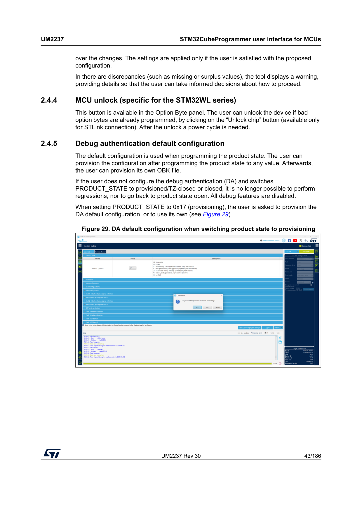
UM2237 Rev 30 43/186
Um2237
STM32CubeProgrammer user interface for MCUs 185 over the changes. The settings are applied only if the user is satisfied with the proposed configuration. In there are discrepancies (such as missing or surplus values), the tool displays a warning, providing details so that the user can take informed decisions about how to proceed. 2.4.4 MCU unlock (specific for the STM32WL series) This button is available in the Option Byte panel. The user can unlock the device if bad option bytes are already programmed, by clicking on the “Unlock chip” button (available only for STLink connection). After the unlock a power cycle is needed. 2.4.5 Debug authentication default configuration The default configuration is used when programming the product state. The user can provision the configuration after programming the product state to any value. Afterwards, the user can provision its own OBK file. If the user does not configure the debug authentication (DA) and switches PRODUCT_STATE to provisioned/TZ-closed or closed, it is no longer possible to perform regressions, nor to go back to product state open. All debug features are disabled. When setting PRODUCT_STATE to 0x17 (provisioning), the user is asked to provision the DA default configuration, or to use its own (see Figure 29). Figure 29. DA default configuration when switching product state to provisioning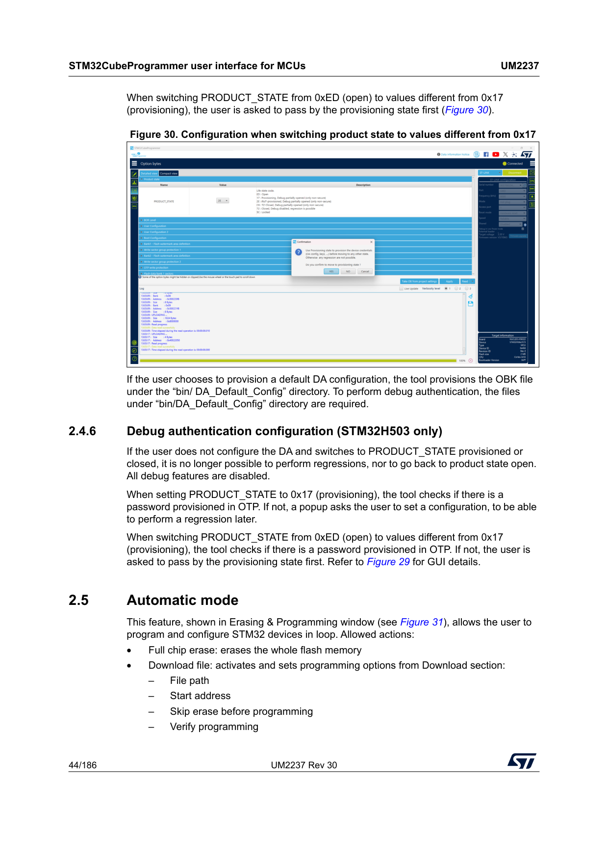
STM32CubeProgrammer user interface for MCUs
Um2237
44/186 UM2237 Rev 30 When switching PRODUCT_STATE from 0xED (open) to values different from 0x17 (provisioning), the user is asked to pass by the provisioning state first (Figure 30). Figure 30. Configuration when switching product state to values different from 0x17 If the user chooses to provision a default DA configuration, the tool provisions the OBK file under the “bin/ DA_Default_Config” directory. To perform debug authentication, the files under “bin/DA_Default_Config” directory are required. 2.4.6 Debug authentication configuration (STM32H503 only) If the user does not configure the DA and switches to PRODUCT_STATE provisioned or closed, it is no longer possible to perform regressions, nor to go back to product state open. All debug features are disabled. When setting PRODUCT_STATE to 0x17 (provisioning), the tool checks if there is a password provisioned in OTP. If not, a popup asks the user to set a configuration, to be able to perform a regression later. When switching PRODUCT_STATE from 0xED (open) to values different from 0x17 (provisioning), the tool checks if there is a password provisioned in OTP. If not, the user is asked to pass by the provisioning state first. Refer to Figure 29 for GUI details. 2.5 Automatic mode This feature, shown in Erasing & Programming window (see Figure 31), allows the user to program and configure STM32 devices in loop. Allowed actions: • Full chip erase: erases the whole flash memory • Download file: activates and sets programming options from Download section: – File path – Start address – Skip erase before programming – Verify programming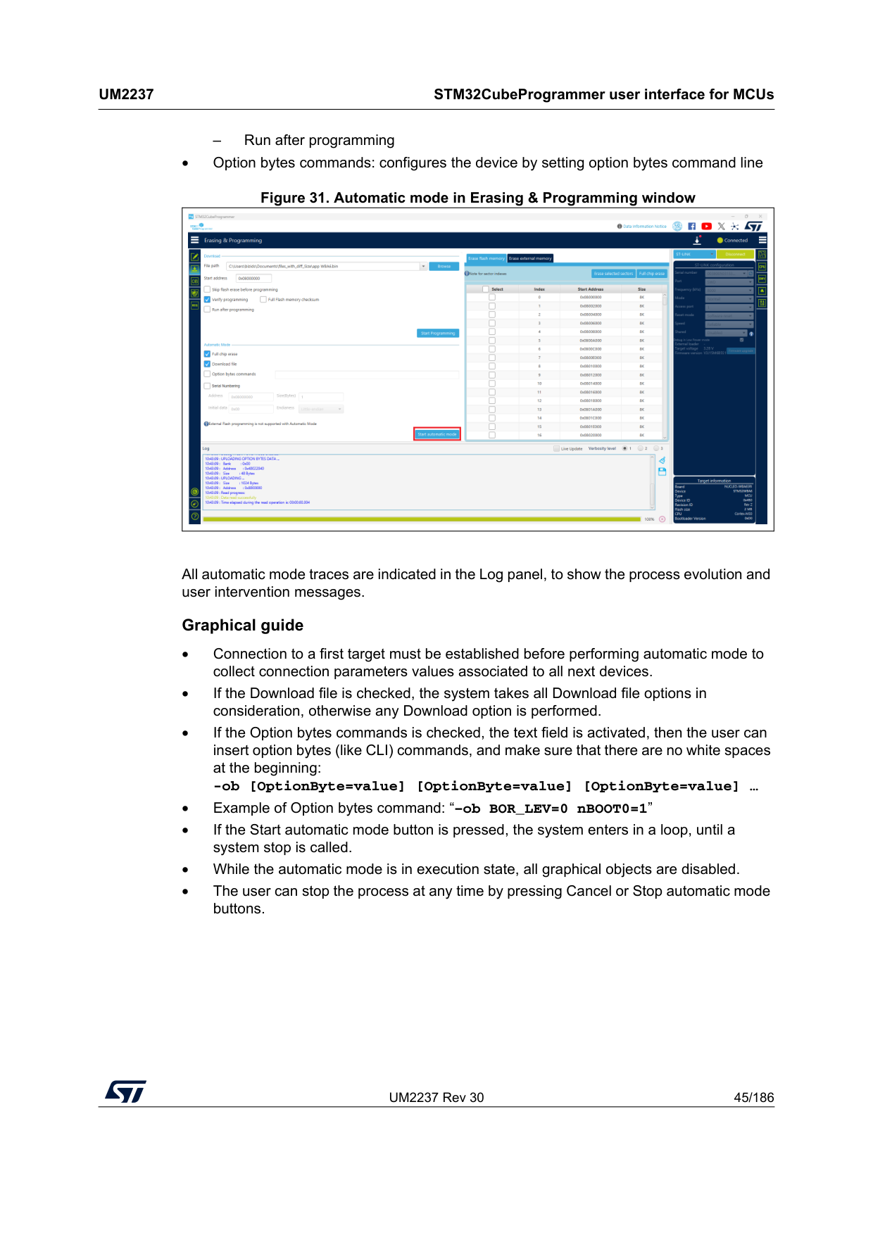
UM2237 Rev 30 45/186
Um2237
STM32CubeProgrammer user interface for MCUs 185 – Run after programming • Option bytes commands: configures the device by setting option bytes command line Figure 31. Automatic mode in Erasing & Programming window All automatic mode traces are indicated in the Log panel, to show the process evolution and user intervention messages. Graphical guide • Connection to a first target must be established before performing automatic mode to collect connection parameters values associated to all next devices. • If the Download file is checked, the system takes all Download file options in consideration, otherwise any Download option is performed. • If the Option bytes commands is checked, the text field is activated, then the user can insert option bytes (like CLI) commands, and make sure that there are no white spaces at the beginning: -ob [OptionByte=value] [OptionByte=value] [OptionByte=value] … • Example of Option bytes command: “–ob BOR_LEV=0 nBOOT0=1” • If the Start automatic mode button is pressed, the system enters in a loop, until a system stop is called. • While the automatic mode is in execution state, all graphical objects are disabled. • The user can stop the process at any time by pressing Cancel or Stop automatic mode buttons.
STM32CubeProgrammer user interface for MCUs
Um2237
46/186 UM2237 Rev 30 Log messages • “Starting Automatic Mode...” Indicates that the system successfully entered the automatic process. • “More than one ST-LINK probe detected! Keep only one ST-LINK probe! “ The automatic mode cannot be used if more than one ST-LINK probe is connected to the computer when using JTAG/SWD interfaces. A message is displayed, asking the user to keep only one ST-LINK probe connected to continue using this mode. • “More than one ST-LINK Bridge detected! Keep only one ST-LINK Bridge!” The automatic mode cannot be used if more than one ST-LINK bridge is connected to the computer when using bootloader interface SPI/CAN/I2C interfaces. A message is displayed, asking the user to keep only one ST-LINK bridge connected to continue using this mode. • “More than one ST-LINK USB DFU detected! Keep only one USB DFU!” The automatic mode cannot be used if more than one USB DFU is connected to the computer when using USB bootloader interface. A message is displayed, asking the user to keep only one USB DFU connected to continue using this mode. • “More UART ports detected than last connection!” During the first connection the automatic mode calculates the number of the available serial ports, and puts it as a reference, to detect correctly that only one port UART is used for each STM32 device. • “Please disconnect device and connect the next...” If the system finishes the first process, and whatever the result, disconnect the current device to prepare the second device connection. • “Waiting for device...” Once the connection to the previous device is correctly lost, the system keeps searching for a new device. • “Automatic Mode is stopped.” Indicates that there is a cancel request, and the system stops the process.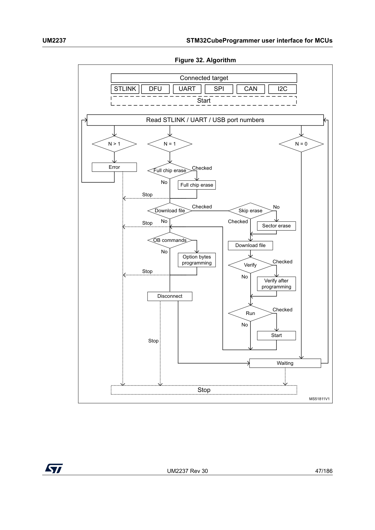
UM2237 Rev 30 47/186
Um2237
STM32CubeProgrammer user interface for MCUs 185 Figure 32. AlgorithmMs51811V1
Connected target StartStlink
Dfu
Uart
Spi
Can
I2C
Read STLINK / UART / USB port numbersN > 1
ErrorN = 1
N = 0
Full chip erase Full chip erase Download file OB commands Option bytes programming Disconnect Waiting Stop Skip erase Sector erase Download file Verify Verify after programming Run Start Checked Checked No No Stop Stop Stop Stop No No Checked Checked Checked No No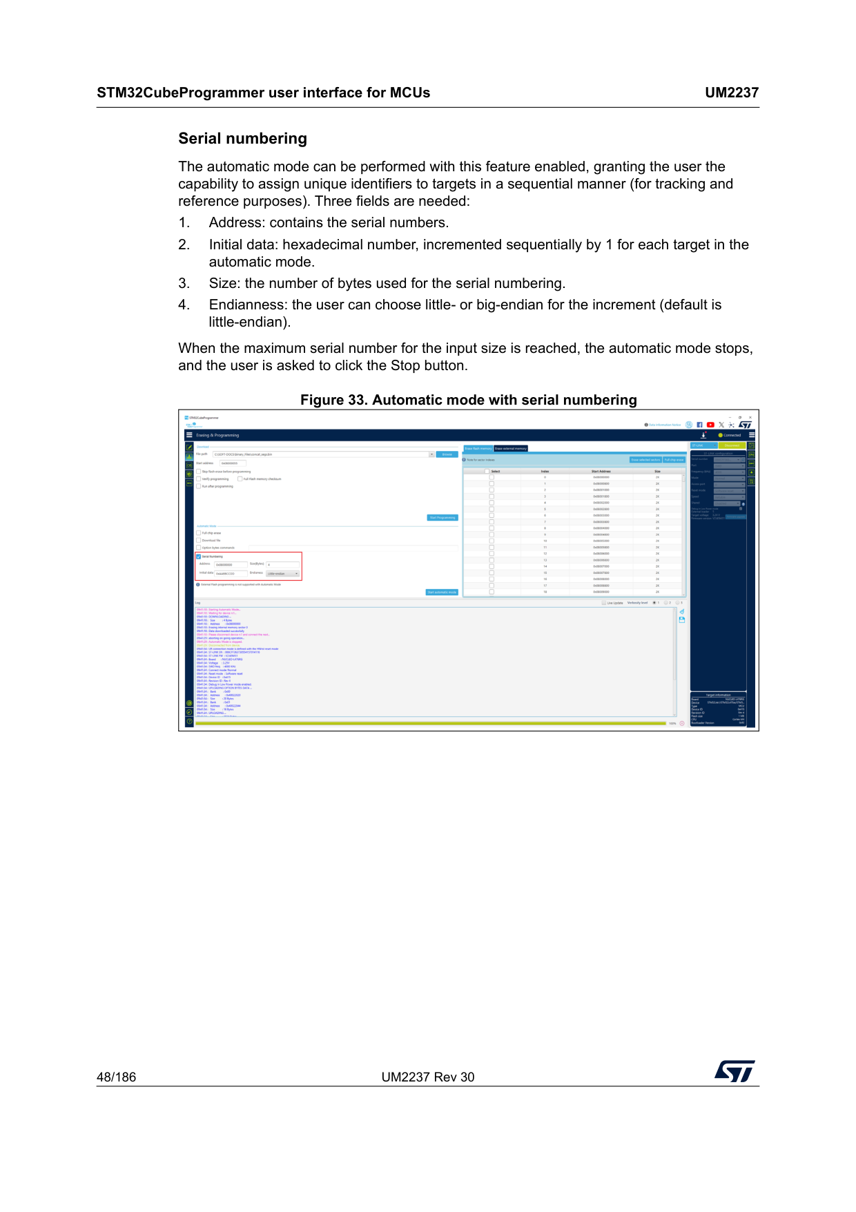
STM32CubeProgrammer user interface for MCUs
Um2237
48/186 UM2237 Rev 30 Serial numbering The automatic mode can be performed with this feature enabled, granting the user the capability to assign unique identifiers to targets in a sequential manner (for tracking and reference purposes). Three fields are needed: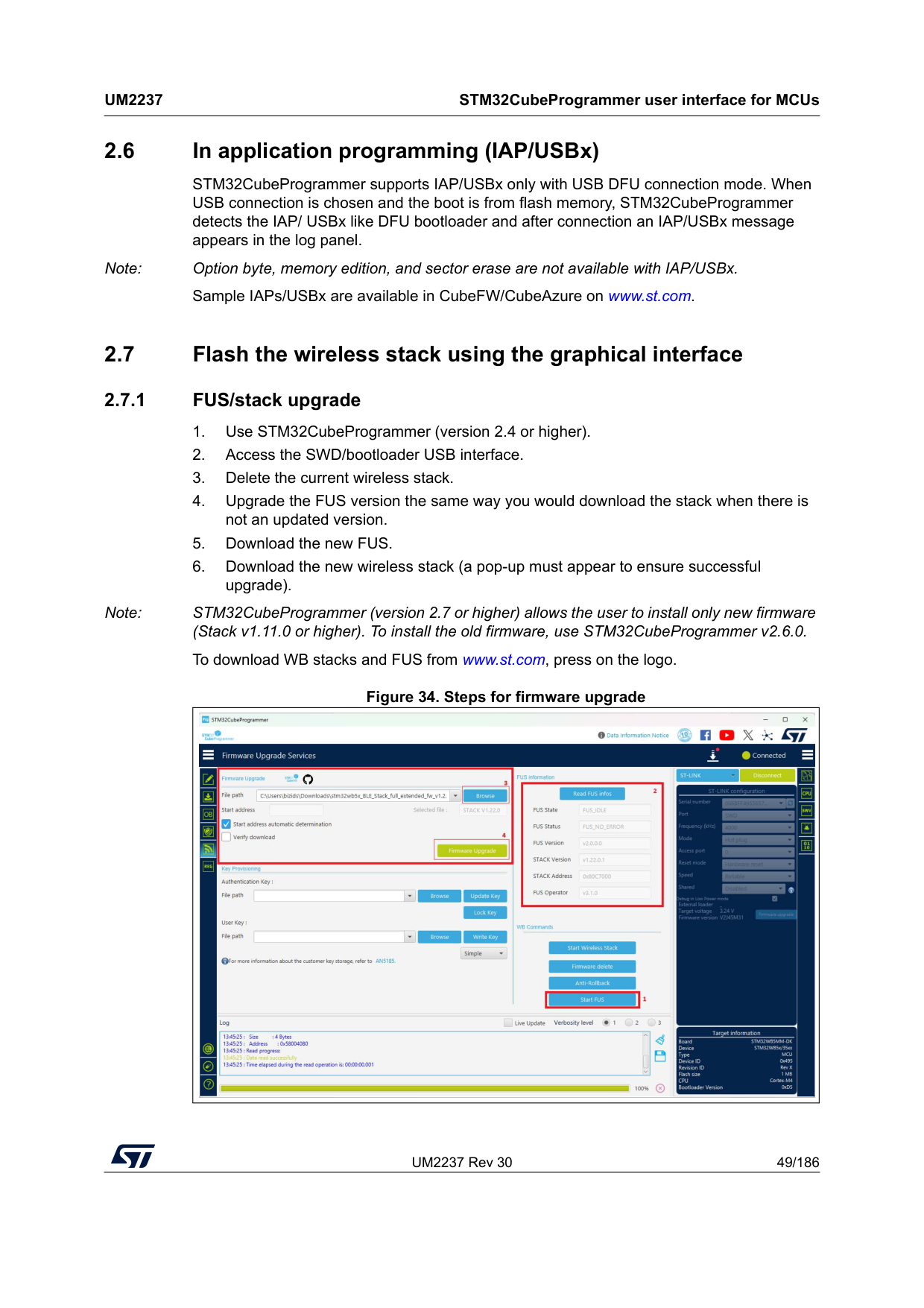
UM2237 Rev 30 49/186
Um2237
STM32CubeProgrammer user interface for MCUs 185 2.6 In application programming (IAP/USBx) STM32CubeProgrammer supports IAP/USBx only with USB DFU connection mode. When USB connection is chosen and the boot is from flash memory, STM32CubeProgrammer detects the IAP/ USBx like DFU bootloader and after connection an IAP/USBx message appears in the log panel. Note: Option byte, memory edition, and sector erase are not available with IAP/USBx. Sample IAPs/USBx are available in CubeFW/CubeAzure on www.st.com. 2.7 Flash the wireless stack using the graphical interface 2.7.1 FUS/stack upgrade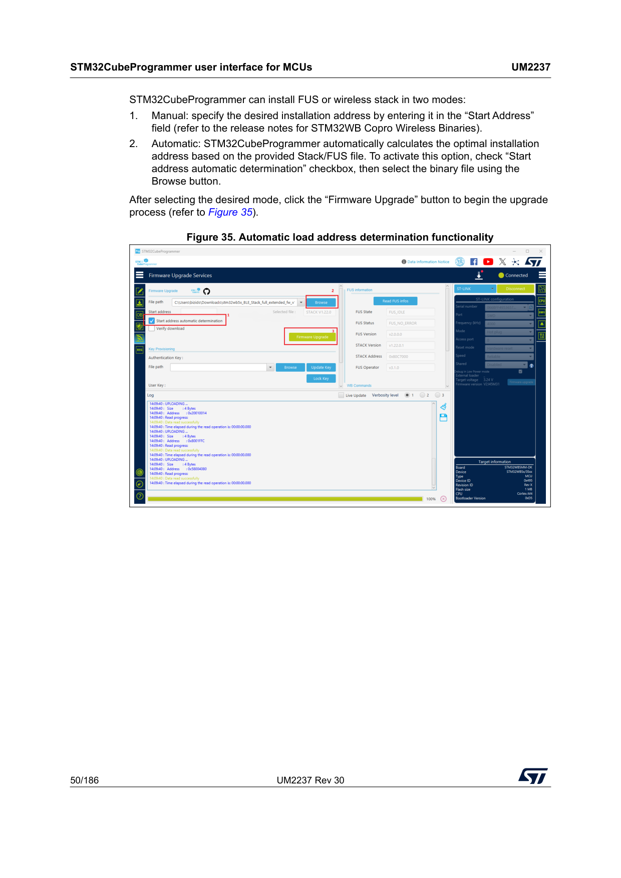
STM32CubeProgrammer user interface for MCUs
Um2237
50/186 UM2237 Rev 30 STM32CubeProgrammer can install FUS or wireless stack in two modes: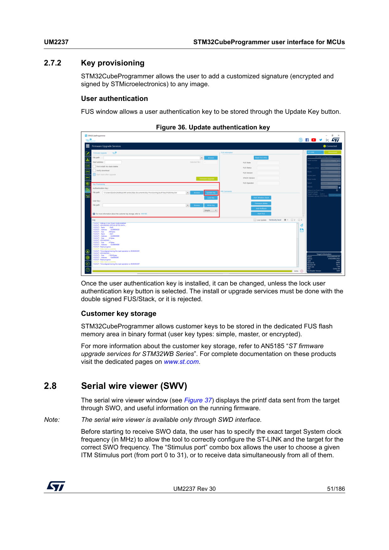
UM2237 Rev 30 51/186
Um2237
STM32CubeProgrammer user interface for MCUs 185 2.7.2 Key provisioning STM32CubeProgrammer allows the user to add a customized signature (encrypted and signed by STMicroelectronics) to any image. User authentication FUS window allows a user authentication key to be stored through the Update Key button. Figure 36. Update authentication key Once the user authentication key is installed, it can be changed, unless the lock user authentication key button is selected. The install or upgrade services must be done with the double signed FUS/Stack, or it is rejected. Customer key storage STM32CubeProgrammer allows customer keys to be stored in the dedicated FUS flash memory area in binary format (user key types: simple, master, or encrypted). For more information about the customer key storage, refer to AN5185 “ST firmware upgrade services for STM32WB Series”. For complete documentation on these products visit the dedicated pages on www.st.com. 2.8 Serial wire viewer (SWV) The serial wire viewer window (see Figure 37) displays the printf data sent from the target through SWO, and useful information on the running firmware. Note: The serial wire viewer is available only through SWD interface. Before starting to receive SWO data, the user has to specify the exact target System clock frequency (in MHz) to allow the tool to correctly configure the ST-LINK and the target for the correct SWO frequency. The “Stimulus port” combo box allows the user to choose a given ITM Stimulus port (from port 0 to 31), or to receive data simultaneously from all of them.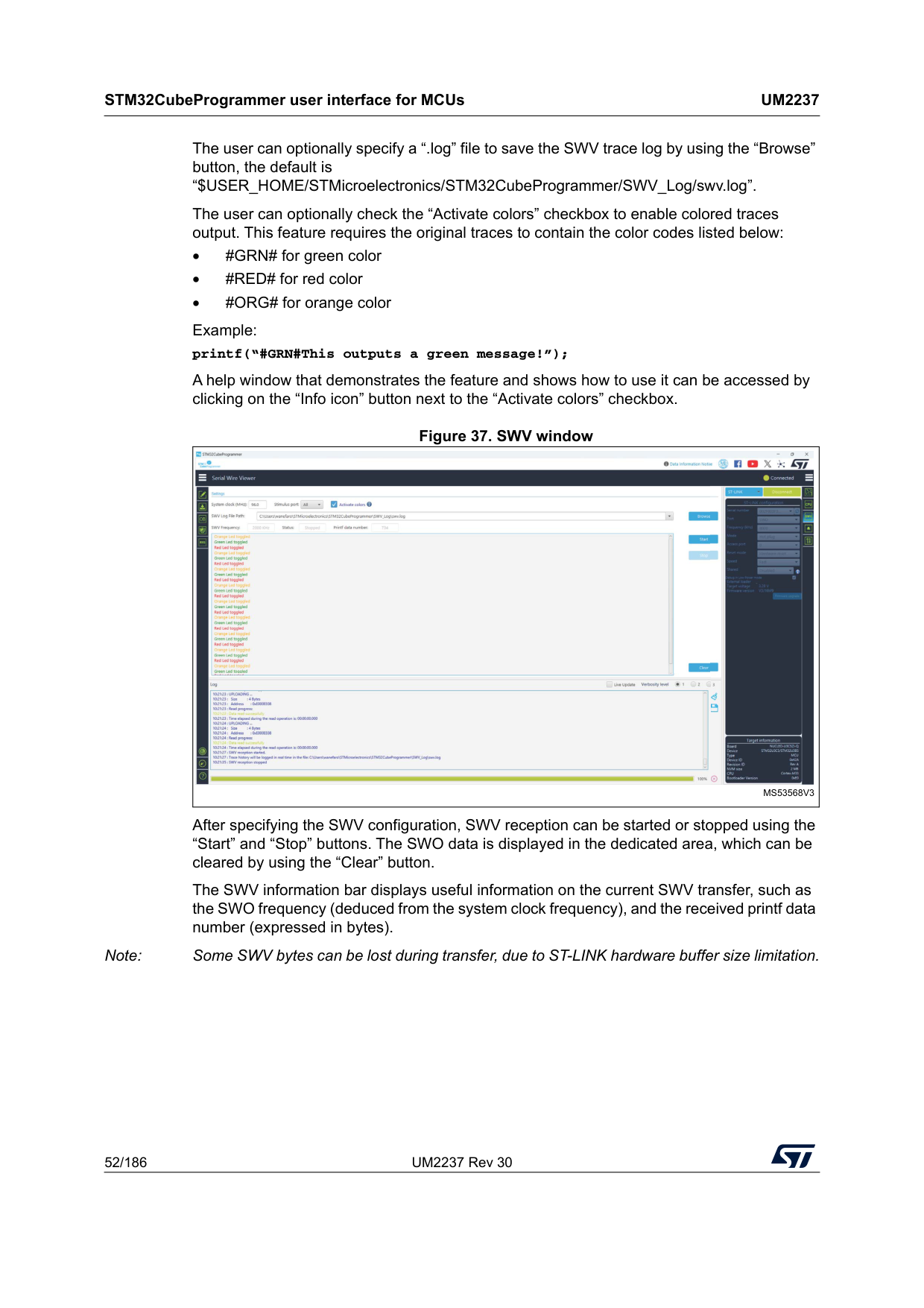
STM32CubeProgrammer user interface for MCUs
Um2237
52/186 UM2237 Rev 30 The user can optionally specify a “.log” file to save the SWV trace log by using the “Browse” button, the default is “$USER_HOME/STMicroelectronics/STM32CubeProgrammer/SWV_Log/swv.log”. The user can optionally check the “Activate colors” checkbox to enable colored traces output. This feature requires the original traces to contain the color codes listed below: • #GRN# for green color • #RED# for red color • #ORG# for orange color Example: printf(“#GRN#This outputs a green message!”); A help window that demonstrates the feature and shows how to use it can be accessed by clicking on the “Info icon” button next to the “Activate colors” checkbox. Figure 37. SWV window After specifying the SWV configuration, SWV reception can be started or stopped using the “Start” and “Stop” buttons. The SWO data is displayed in the dedicated area, which can be cleared by using the “Clear” button. The SWV information bar displays useful information on the current SWV transfer, such as the SWO frequency (deduced from the system clock frequency), and the received printf data number (expressed in bytes). Note: Some SWV bytes can be lost during transfer, due to ST-LINK hardware buffer size limitation.Ms53568V3
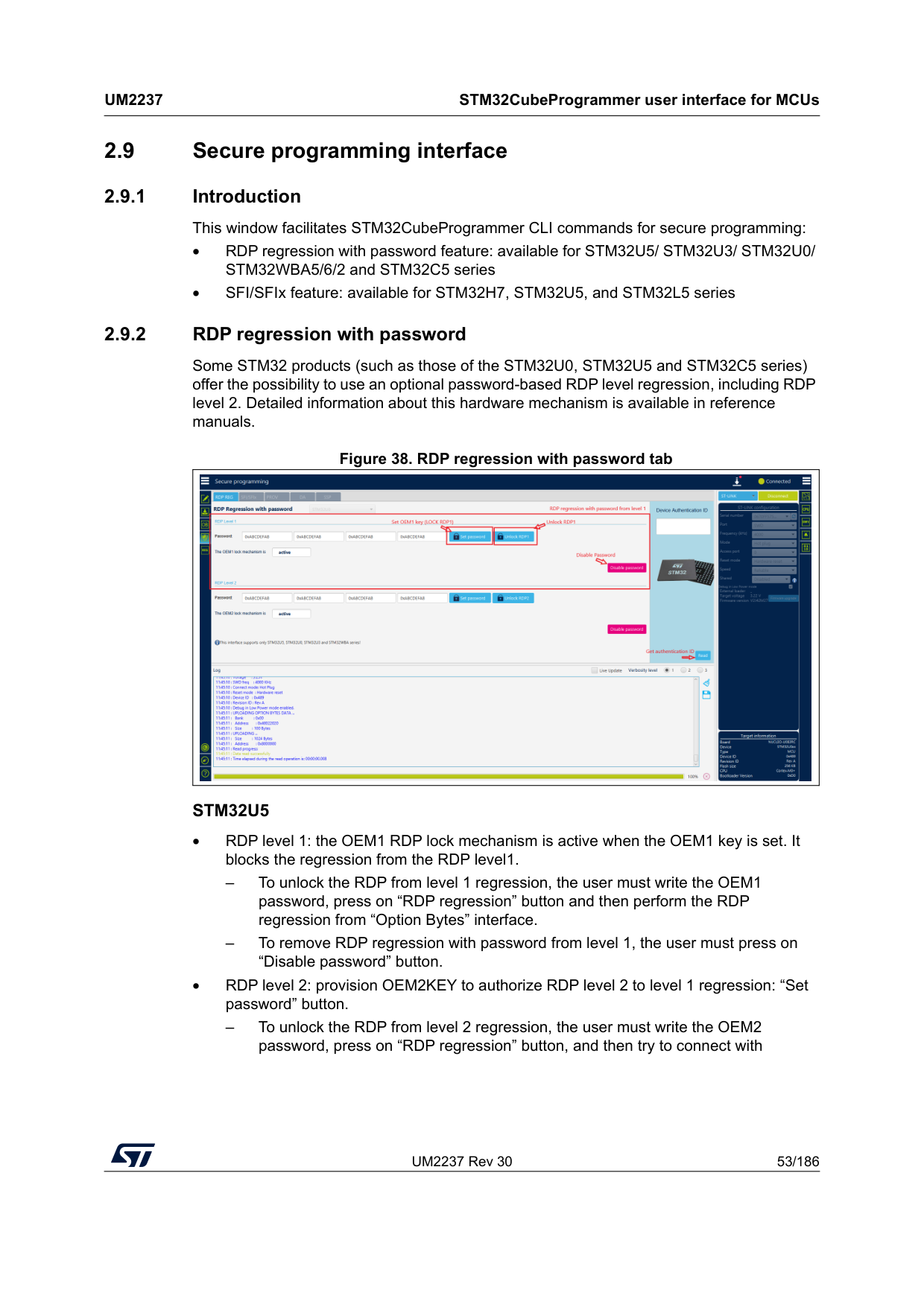
UM2237 Rev 30 53/186
Um2237
STM32CubeProgrammer user interface for MCUs 185 2.9 Secure programming interface 2.9.1 Introduction This window facilitates STM32CubeProgrammer CLI commands for secure programming: • RDP regression with password feature: available for STM32U5/ STM32U3/ STM32U0/ STM32WBA5/6/2 and STM32C5 series • SFI/SFIx feature: available for STM32H7, STM32U5, and STM32L5 series 2.9.2 RDP regression with password Some STM32 products (such as those of the STM32U0, STM32U5 and STM32C5 series) offer the possibility to use an optional password-based RDP level regression, including RDP level 2. Detailed information about this hardware mechanism is available in reference manuals. Figure 38. RDP regression with password tabStm32U5
• RDP level 1: the OEM1 RDP lock mechanism is active when the OEM1 key is set. It blocks the regression from the RDP level1. – To unlock the RDP from level 1 regression, the user must write the OEM1 password, press on “RDP regression” button and then perform the RDP regression from “Option Bytes” interface. – To remove RDP regression with password from level 1, the user must press on “Disable password” button. • RDP level 2: provision OEM2KEY to authorize RDP level 2 to level 1 regression: “Set password” button. – To unlock the RDP from level 2 regression, the user must write the OEM2 password, press on “RDP regression” button, and then try to connect with
STM32CubeProgrammer user interface for MCUs
Um2237
54/186 UM2237 Rev 30 STM32CubeProgrammer. If this key matches the OEM2KEY value, the RDP regression to level 1 is launched by hardware. – To remove RDP regression with password from level 2, the user must press on “Disable password” button. • Device authentication ID: Get device identification. Unless the JTAG port is deactivated (OEM2LOCK = 0 and RDP level = 2), a 32-bit device specific quantity can be always read through the JTAG port. The OEM can use this 32-bit information to derive the expected OEM password keys to unlock the device.Stm32U0
• RDP level 1: the OEM1 RDP lock mechanism is active when the OEM1 key is set. It blocks the regression from the RDP level1 – To unlock the RDP from level 1 regression, the user must connect in hotplug mode on access port 1, write the OEM1 password, press on “RDP regression” button, and then perform the RDP regression from “Option Bytes” interface. – To remove RDP regression with password from level 1, the user must press on “Disable password” button. • RDP level 2: provision OEM2KEY to authorize RDP level 2 to level 1 regression: “Set password” button. – To unlock the RDP from level 2 regression, write the OEM2 password, press on “RDP regression” button, and then try to connect with STM32CubeProgrammer. If the key matches the OEM2KEY value, the RDP regression to level 1 is launched by hardware. In this use case, the connection is done with ap = 1. – To remove RDP regression with password from level 2, the user must press on the “Disable password” button. Note: For more details, please refer to 7. Annex. (Usage of the unlockrdp2 Command)Stm32C5
• RDP level 2: Provision OEM2KEY to authorize regression from RDP level 2 / Level 2- with-Boundary-Scan to level 0 using “Set password” button. – To perform the regression from RDP level 2, write the OEM2 password, press “RDP regression” button, and then connect with STM32CubeProgrammer. If the key matches the OEM2KEY value stored in the device, the RDP regression to level 0 is launched by hardware. • BSKEY Management: RDP Level 2 with Boundary Scan can transition to RDP Level 2 using the BSKEY, a 32-bits password. The BSKEY must be set when in RDP level 0. Note: A default value (0xAAAAAAAA) is preloaded during manufacturing. – To transition RDP Level 2 with Boundary Scan to RDP Level 2, set the password then select the “transition” button, without connecting to the target.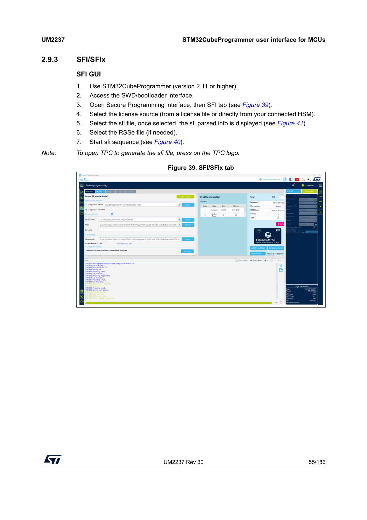
UM2237 Rev 30 55/186
Um2237
STM32CubeProgrammer user interface for MCUs 185 2.9.3 SFI/SFIxSfi Gui
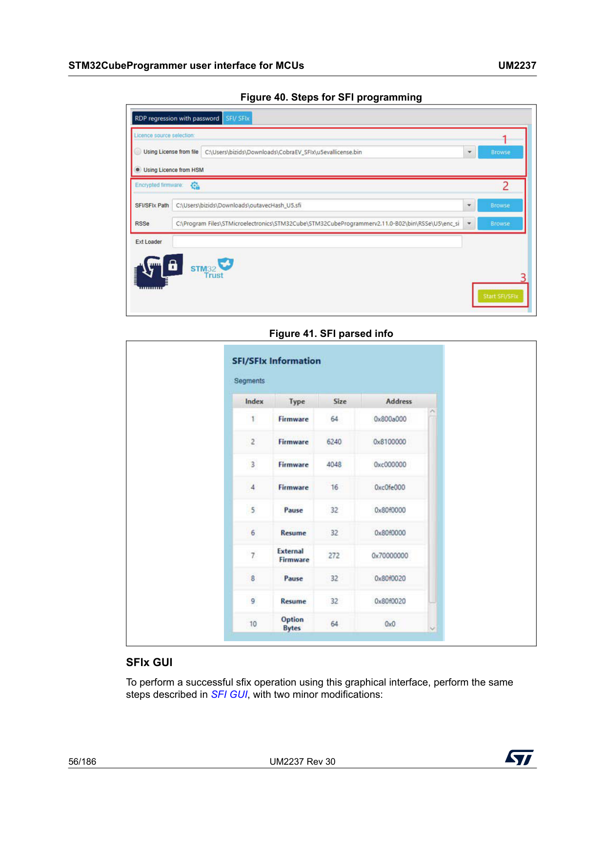
STM32CubeProgrammer user interface for MCUs
Um2237
56/186 UM2237 Rev 30 Figure 40. Steps for SFI programming Figure 41. SFI parsed info SFIx GUI To perform a successful sfix operation using this graphical interface, perform the same steps described in SFI GUI, with two minor modifications:
UM2237 Rev 30 57/186
Um2237
STM32CubeProgrammer user interface for MCUs 185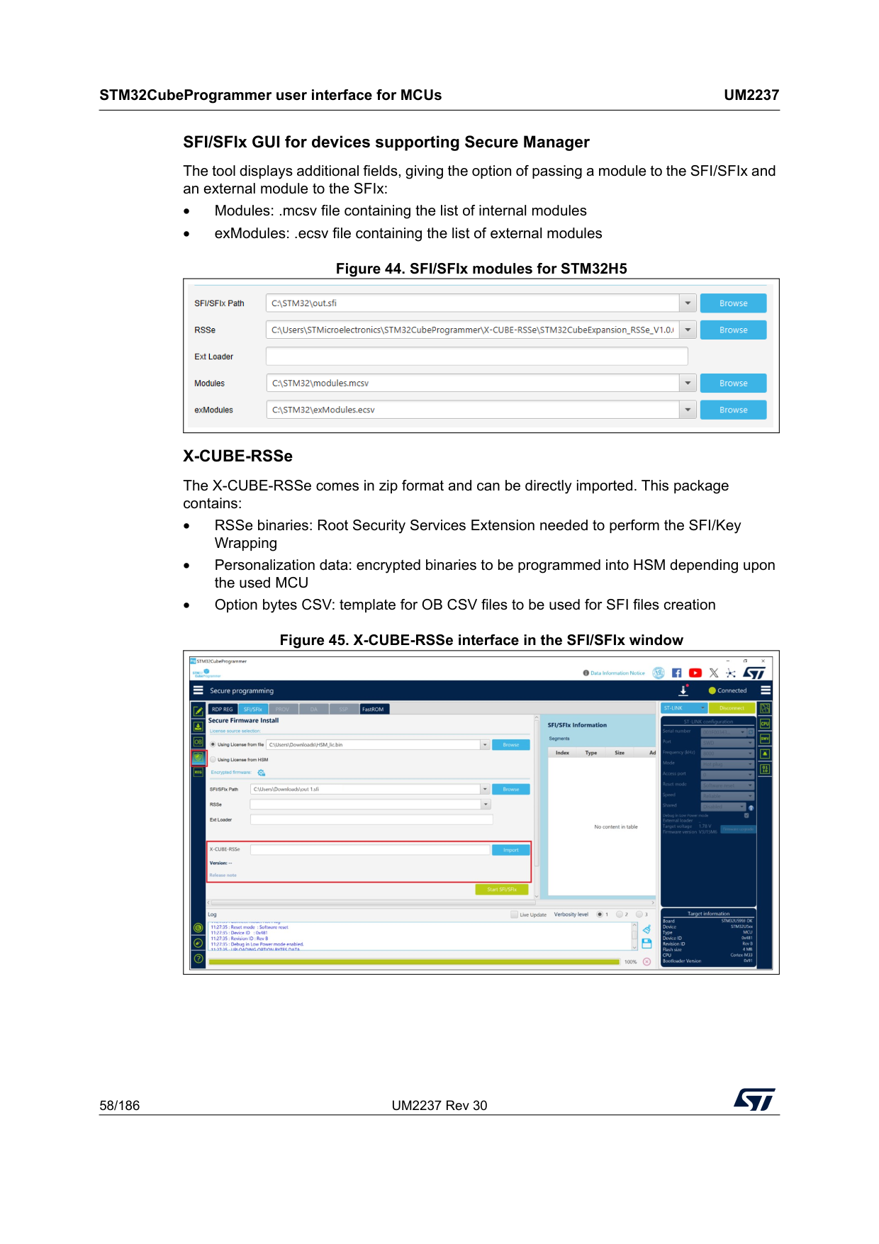
STM32CubeProgrammer user interface for MCUs
Um2237
58/186 UM2237 Rev 30 SFI/SFIx GUI for devices supporting Secure Manager The tool displays additional fields, giving the option of passing a module to the SFI/SFIx and an external module to the SFIx: • Modules: .mcsv file containing the list of internal modules • exModules: .ecsv file containing the list of external modules Figure 44. SFI/SFIx modules for STM32H5 X-CUBE-RSSe The X-CUBE-RSSe comes in zip format and can be directly imported. This package contains: • RSSe binaries: Root Security Services Extension needed to perform the SFI/Key Wrapping • Personalization data: encrypted binaries to be programmed into HSM depending upon the used MCU • Option bytes CSV: template for OB CSV files to be used for SFI files creation Figure 45. X-CUBE-RSSe interface in the SFI/SFIx window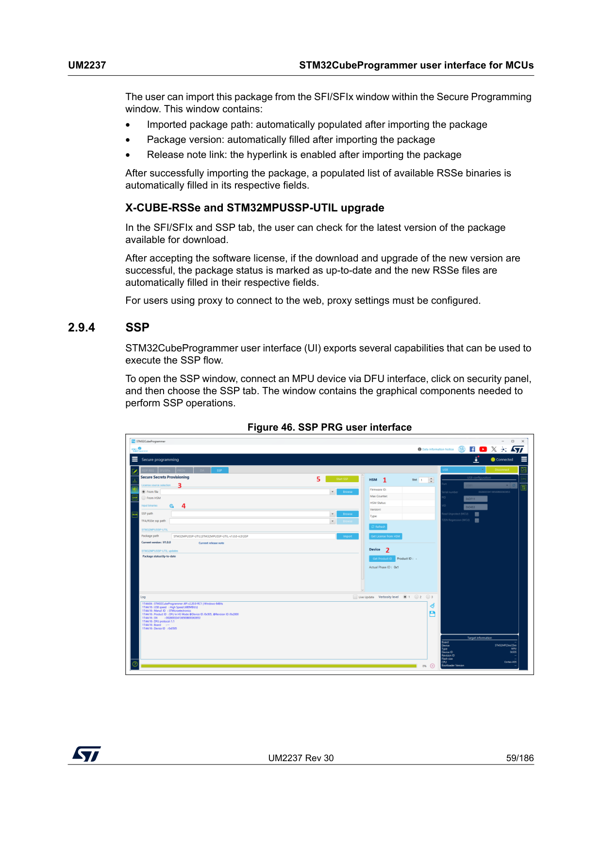
UM2237 Rev 30 59/186
Um2237
STM32CubeProgrammer user interface for MCUs 185 The user can import this package from the SFI/SFIx window within the Secure Programming window. This window contains: • Imported package path: automatically populated after importing the package • Package version: automatically filled after importing the package • Release note link: the hyperlink is enabled after importing the package After successfully importing the package, a populated list of available RSSe binaries is automatically filled in its respective fields. X-CUBE-RSSe and STM32MPUSSP-UTIL upgrade In the SFI/SFIx and SSP tab, the user can check for the latest version of the package available for download. After accepting the software license, if the download and upgrade of the new version are successful, the package status is marked as up-to-date and the new RSSe files are automatically filled in their respective fields. For users using proxy to connect to the web, proxy settings must be configured. 2.9.4Ssp
STM32CubeProgrammer user interface (UI) exports several capabilities that can be used to execute the SSP flow. To open the SSP window, connect an MPU device via DFU interface, click on security panel, and then choose the SSP tab. The window contains the graphical components needed to perform SSP operations. Figure 46. SSP PRG user interface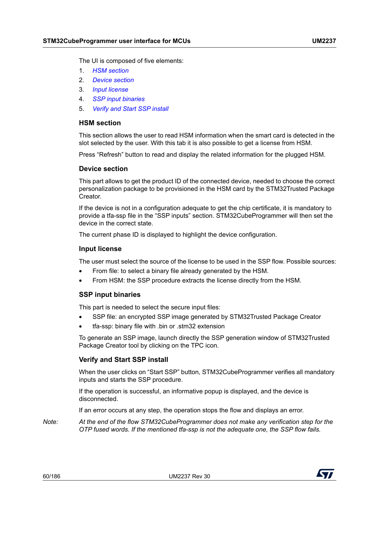
STM32CubeProgrammer user interface for MCUs
Um2237
60/186 UM2237 Rev 30 The UI is composed of five elements: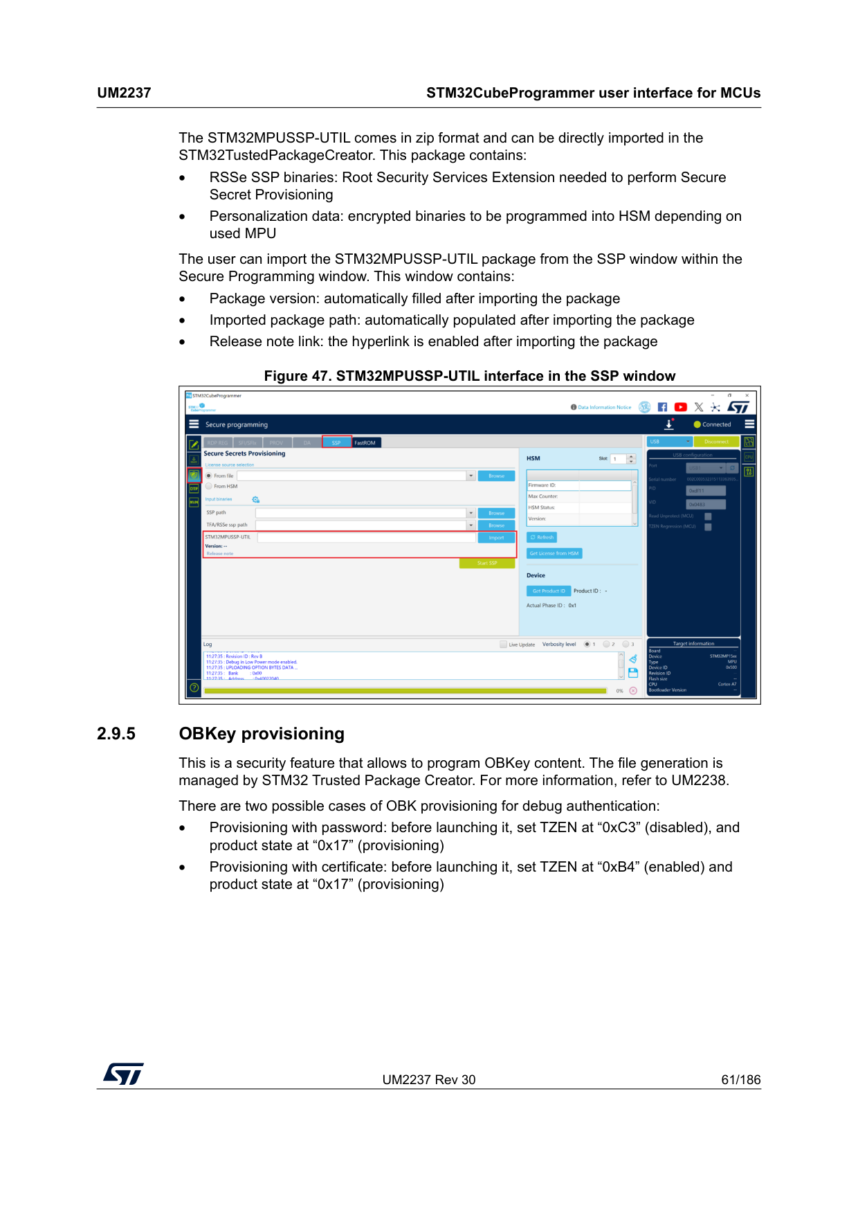
UM2237 Rev 30 61/186
Um2237
STM32CubeProgrammer user interface for MCUs 185 The STM32MPUSSP-UTIL comes in zip format and can be directly imported in the STM32TustedPackageCreator. This package contains: • RSSe SSP binaries: Root Security Services Extension needed to perform Secure Secret Provisioning • Personalization data: encrypted binaries to be programmed into HSM depending on used MPU The user can import the STM32MPUSSP-UTIL package from the SSP window within the Secure Programming window. This window contains: • Package version: automatically filled after importing the package • Imported package path: automatically populated after importing the package • Release note link: the hyperlink is enabled after importing the package Figure 47. STM32MPUSSP-UTIL interface in the SSP window 2.9.5 OBKey provisioning This is a security feature that allows to program OBKey content. The file generation is managed by STM32 Trusted Package Creator. For more information, refer to UM2238. There are two possible cases of OBK provisioning for debug authentication: • Provisioning with password: before launching it, set TZEN at “0xC3” (disabled), and product state at “0x17” (provisioning) • Provisioning with certificate: before launching it, set TZEN at “0xB4” (enabled) and product state at “0x17” (provisioning)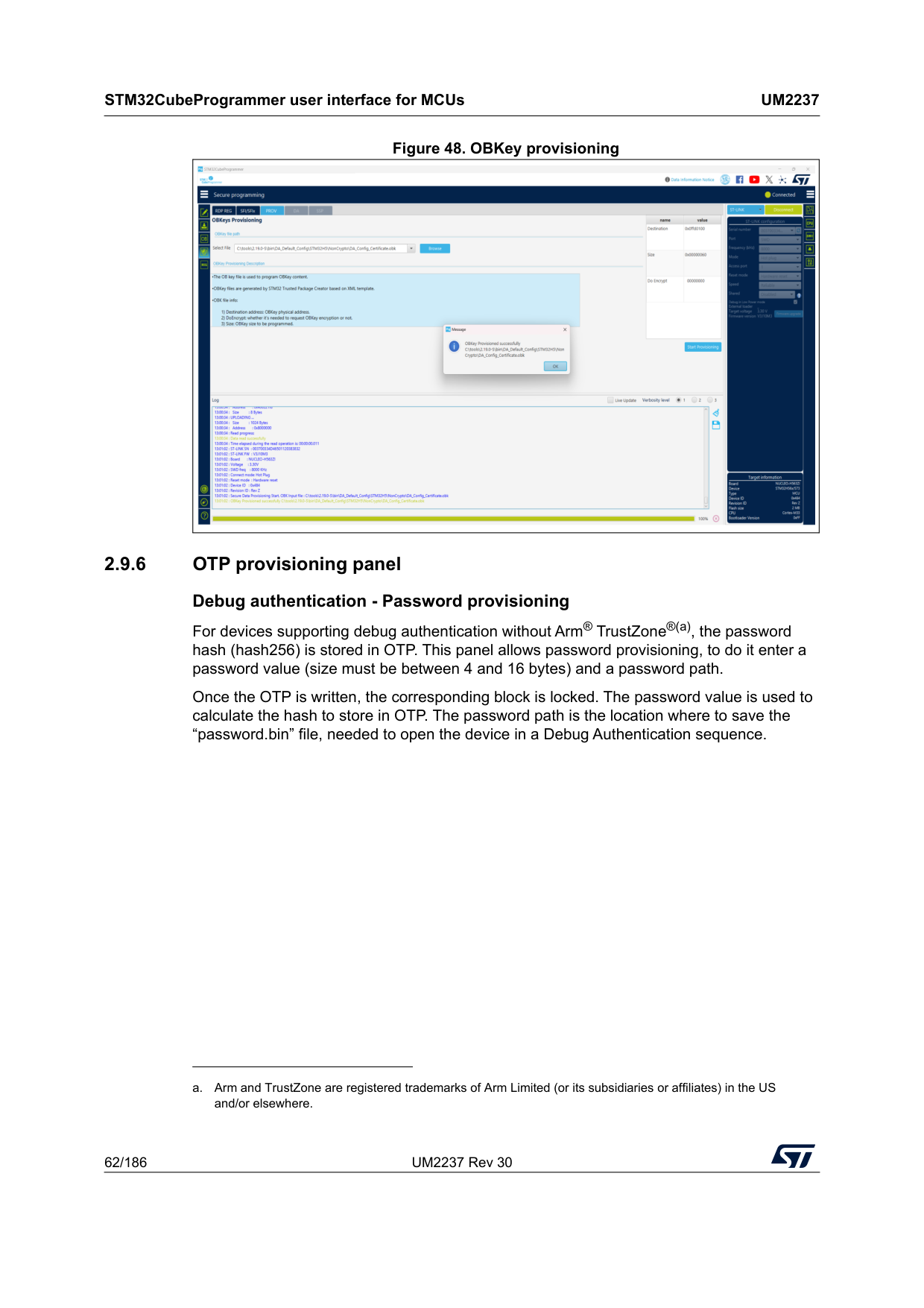
STM32CubeProgrammer user interface for MCUs
Um2237
62/186 UM2237 Rev 30 Figure 48. OBKey provisioning 2.9.6 OTP provisioning panel Debug authentication - Password provisioning For devices supporting debug authentication without Arm® TrustZone®(a), the password hash (hash256) is stored in OTP. This panel allows password provisioning, to do it enter a password value (size must be between 4 and 16 bytes) and a password path. Once the OTP is written, the corresponding block is locked. The password value is used to calculate the hash to store in OTP. The password path is the location where to save the “password.bin” file, needed to open the device in a Debug Authentication sequence. a. Arm and TrustZone are registered trademarks of Arm Limited (or its subsidiaries or affiliates) in the US and/or elsewhere.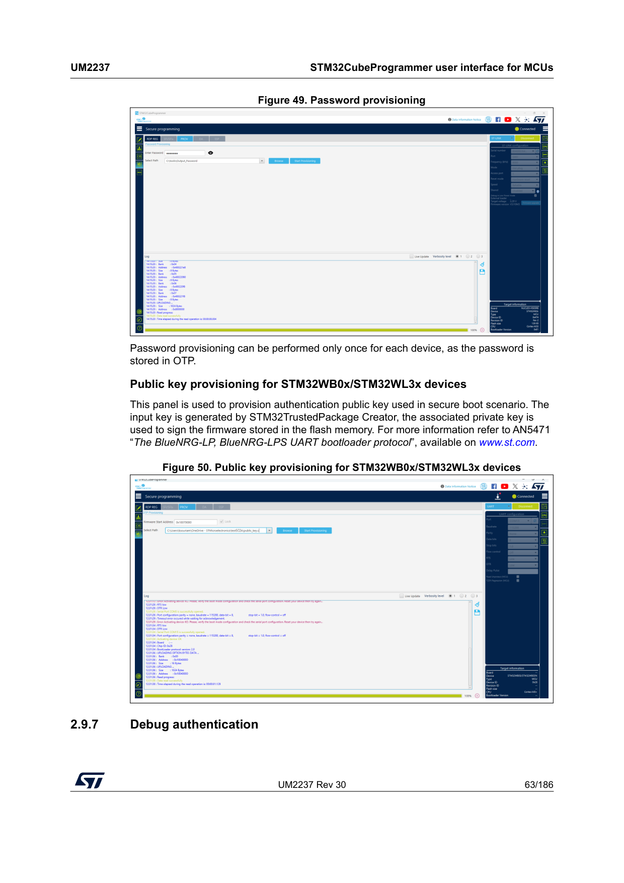
UM2237 Rev 30 63/186
Um2237
STM32CubeProgrammer user interface for MCUs 185 Figure 49. Password provisioning Password provisioning can be performed only once for each device, as the password is stored in OTP. Public key provisioning for STM32WB0x/STM32WL3x devices This panel is used to provision authentication public key used in secure boot scenario. The input key is generated by STM32TrustedPackage Creator, the associated private key is used to sign the firmware stored in the flash memory. For more information refer to AN5471 “The BlueNRG-LP, BlueNRG-LPS UART bootloader protocol”, available on www.st.com. Figure 50. Public key provisioning for STM32WB0x/STM32WL3x devices 2.9.7 Debug authentication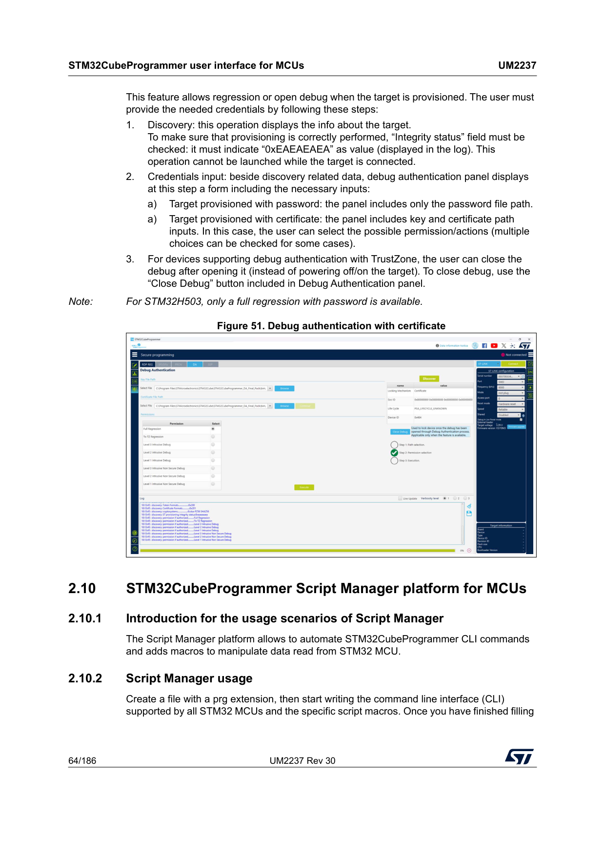
STM32CubeProgrammer user interface for MCUs
Um2237
64/186 UM2237 Rev 30 This feature allows regression or open debug when the target is provisioned. The user must provide the needed credentials by following these steps: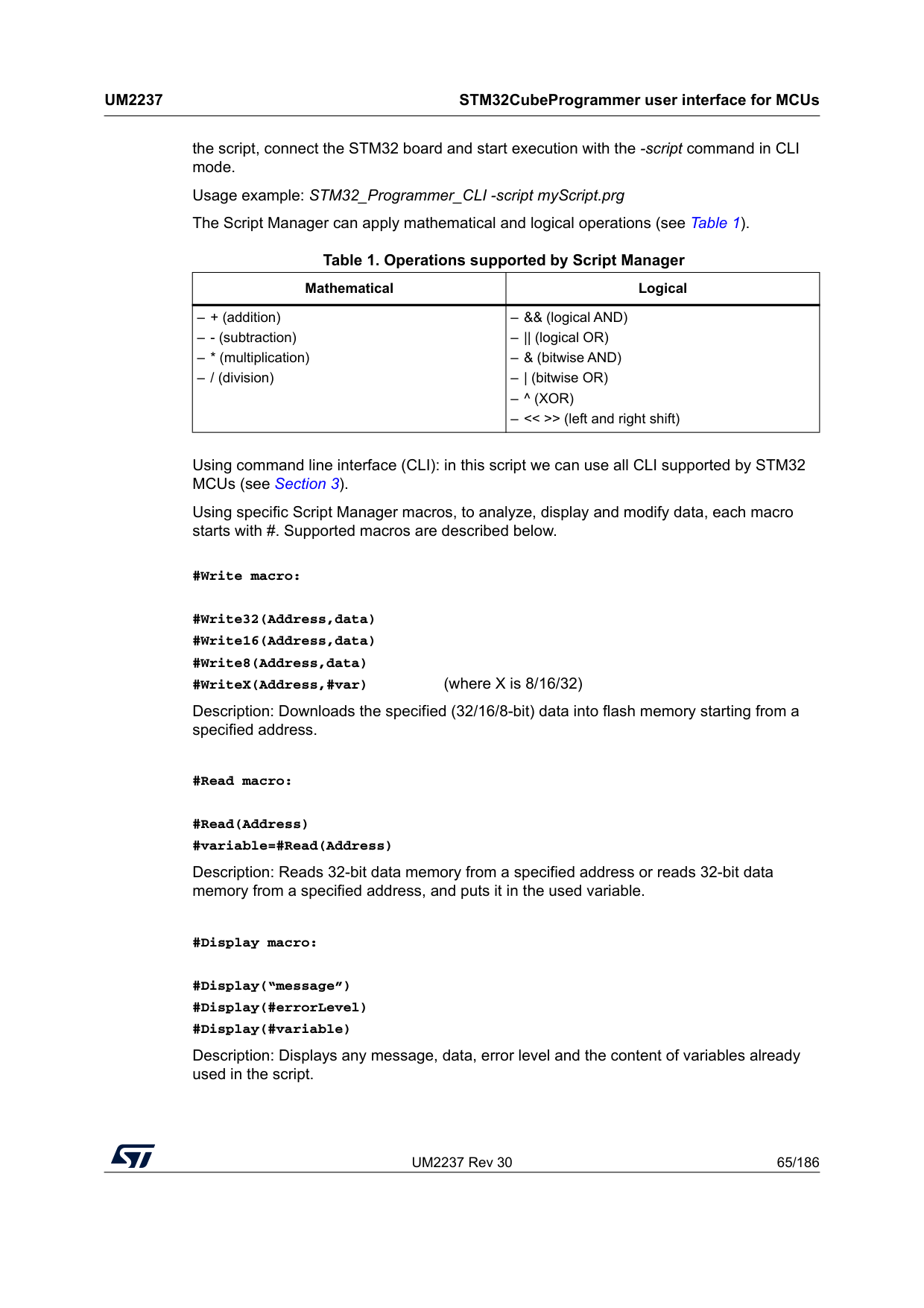
UM2237 Rev 30 65/186
Um2237
STM32CubeProgrammer user interface for MCUs 185 the script, connect the STM32 board and start execution with the -script command in CLI mode. Usage example: STM32_Programmer_CLI -script myScript.prg The Script Manager can apply mathematical and logical operations (see Table 1).Using command line interface (CLI): in this script we can use all CLI supported by STM32 MCUs (see Section 3). Using specific Script Manager macros, to analyze, display and modify data, each macro starts with #. Supported macros are described below. #Write macro: #Write32(Address,data) #Write16(Address,data) #Write8(Address,data) #WriteX(Address,#var) (where X is 8/16/32) Description: Downloads the specified (32/16/8-bit) data into flash memory starting from a specified address. #Read macro: #Read(Address) #variable=#Read(Address) Description: Reads 32-bit data memory from a specified address or reads 32-bit data memory from a specified address, and puts it in the used variable. #Display macro: #Display(“message”) #Display(#errorLevel) #Display(#variable) Description: Displays any message, data, error level and the content of variables already used in the script. Table 1. Operations supported by Script Manager Mathematical Logical – + (addition) – - (subtraction) – * (multiplication) – / (division) – && (logical AND) – || (logical OR) – & (bitwise AND) – | (bitwise OR)
– ^ (Xor)
– << >> (left and right shift)
STM32CubeProgrammer user interface for MCUs
Um2237
66/186 UM2237 Rev 30 #Delay macro: #Delay(Time) Description: Allows user to put the system in standby for a period in (ms). Calculate macro: #variable=[var1] op [var2] #variable=var1 shift (number of bits to shifted) Description: Calculates with mathematical and logical operations in script manager. Disconnection command --scriptdisconnect Description: Allows user to disconnect the device and reconnect to another port in the same script. Note: Comments in the Script Manager can be added by using “//”, as shown in the examples. Script Manager example 1 (CLI and Script macro), see Figure 52 -c port=swd -e 0 1 #Write32(0x08000000,0xAAAABBBB) #var0=#Read(0x08000000) #Display(#var0) Script Manager example 2, see Figure 53 -c port=swd #Write32(0x08000000,0xAAAABBBB) --scriptdisconnect #Delay(5000) -c port=COM17 #Write16(0x08000004,0xCCCC) Script Manager example 3 -c port=swd #Display (”Hello World!”) -e 0 1 #Write32(0x08000000,0xAAAABBBB) #Read(0x08000000) -r32 0x08000000 0x50 #var0=#Read(0x08000000) #Display(#errorLevel) #Display(#var0) #Write32(0x08000004,#var0) #Delay(3000)
UM2237 Rev 30 67/186
Um2237
STM32CubeProgrammer user interface for MCUs 185 #Write16(0x08000008,0xCCCC) #Read(0x08000004) #Display(#errorLevel) #var1=#Read(0x08000008) #Display(#var1) #Write8(0x08000010,0xDD) #Delay(5000) #var2=#Read(0x08000010) #Display(#var2) #var3=(((0xbb*1)+(1-1))/1) #Display(#var3) #Write8(0x08000014,#var3) #var4=((0xbb & 0xaa)| 0xbb ) #Display(#var4) #var5=((0xbb && 0xaa) || 0xbb ) #Display(#var5) #var6=(0xbb >>1) #Display(#var6) -e 0 1 -w32 0x08000000 0xAAAAAAAA -r32 0x08000000 0x50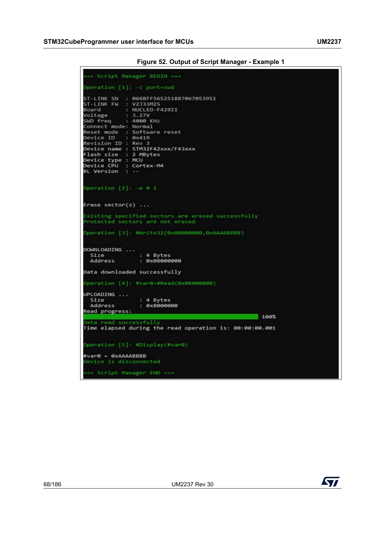
STM32CubeProgrammer user interface for MCUs
Um2237
68/186 UM2237 Rev 30 Figure 52. Output of Script Manager - Example 1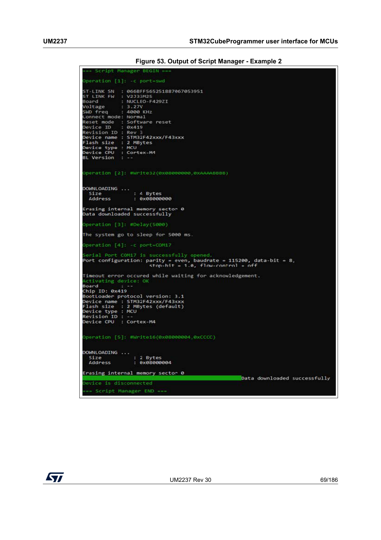
UM2237 Rev 30 69/186
Um2237
STM32CubeProgrammer user interface for MCUs 185 Figure 53. Output of Script Manager - Example 2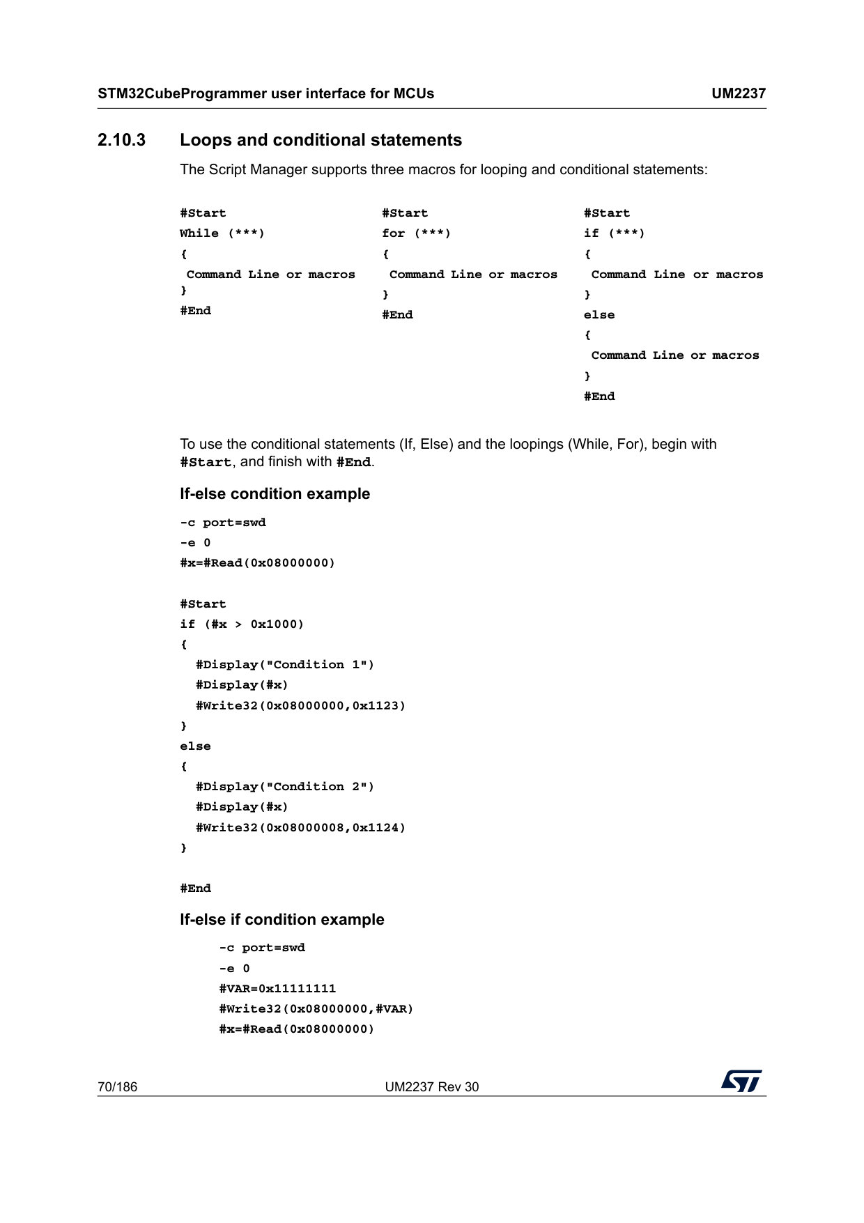
STM32CubeProgrammer user interface for MCUs
Um2237
70/186 UM2237 Rev 30 2.10.3 Loops and conditional statements The Script Manager supports three macros for looping and conditional statements:To use the conditional statements (If, Else) and the loopings (While, For), begin with #Start, and finish with #End. If-else condition example -c port=swd -e 0 #x=#Read(0x08000000) #Start if (#x > 0x1000) { #Display("Condition 1") #Display(#x) #Write32(0x08000000,0x1123) } else { #Display("Condition 2") #Display(#x) #Write32(0x08000008,0x1124) } #End If-else if condition example -c port=swd -e 0 #VAR=0x11111111 #Write32(0x08000000,#VAR) #x=#Read(0x08000000) #Start While (***) { Command Line or macros } #End #Start for (***) { Command Line or macros } #End #Start if (***) { Command Line or macros } else { Command Line or macros } #End
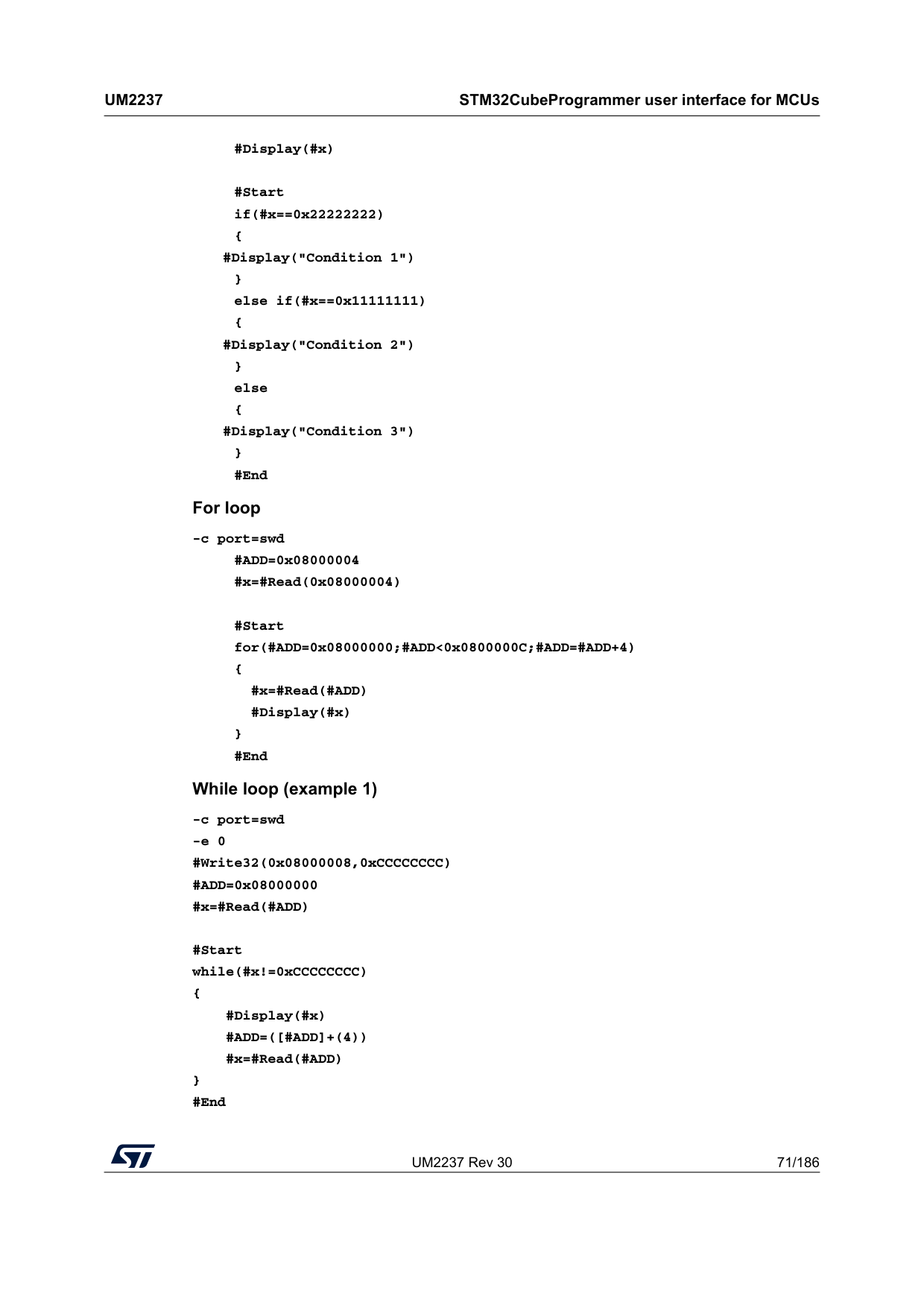
UM2237 Rev 30 71/186
Um2237
STM32CubeProgrammer user interface for MCUs 185 #Display(#x) #Start if(#x==0x22222222) { #Display("Condition 1") } else if(#x==0x11111111) { #Display("Condition 2") } else { #Display("Condition 3") } #End For loop -c port=swd #ADD=0x08000004 #x=#Read(0x08000004) #Start for(#ADD=0x08000000;#ADD<0x0800000C;#ADD=#ADD+4) { #x=#Read(#ADD) #Display(#x) } #End While loop (example 1) -c port=swd -e 0 #Write32(0x08000008,0xCCCCCCCC) #ADD=0x08000000 #x=#Read(#ADD) #Start while(#x!=0xCCCCCCCC) { #Display(#x)#Add=([#Add]+(4))
#x=#Read(#ADD) } #End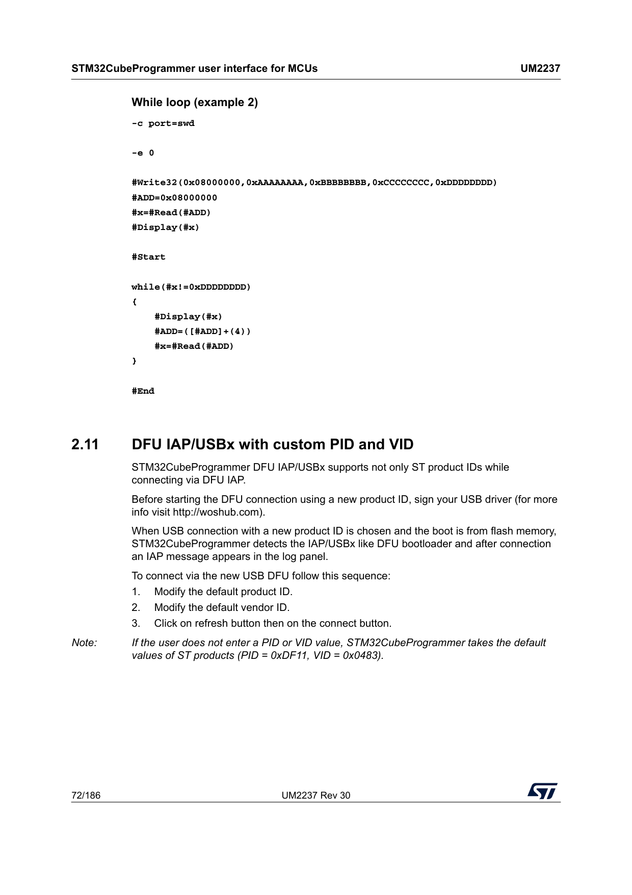
STM32CubeProgrammer user interface for MCUs
Um2237
72/186 UM2237 Rev 30 While loop (example 2) -c port=swd -e 0 #Write32(0x08000000,0xAAAAAAAA,0xBBBBBBBB,0xCCCCCCCC,0xDDDDDDDD) #ADD=0x08000000 #x=#Read(#ADD) #Display(#x) #Start while(#x!=0xDDDDDDDD) { #Display(#x)#Add=([#Add]+(4))
#x=#Read(#ADD) } #End 2.11 DFU IAP/USBx with custom PID and VID STM32CubeProgrammer DFU IAP/USBx supports not only ST product IDs while connecting via DFU IAP. Before starting the DFU connection using a new product ID, sign your USB driver (for more info visit http://woshub.com). When USB connection with a new product ID is chosen and the boot is from flash memory, STM32CubeProgrammer detects the IAP/USBx like DFU bootloader and after connection an IAP message appears in the log panel. To connect via the new USB DFU follow this sequence: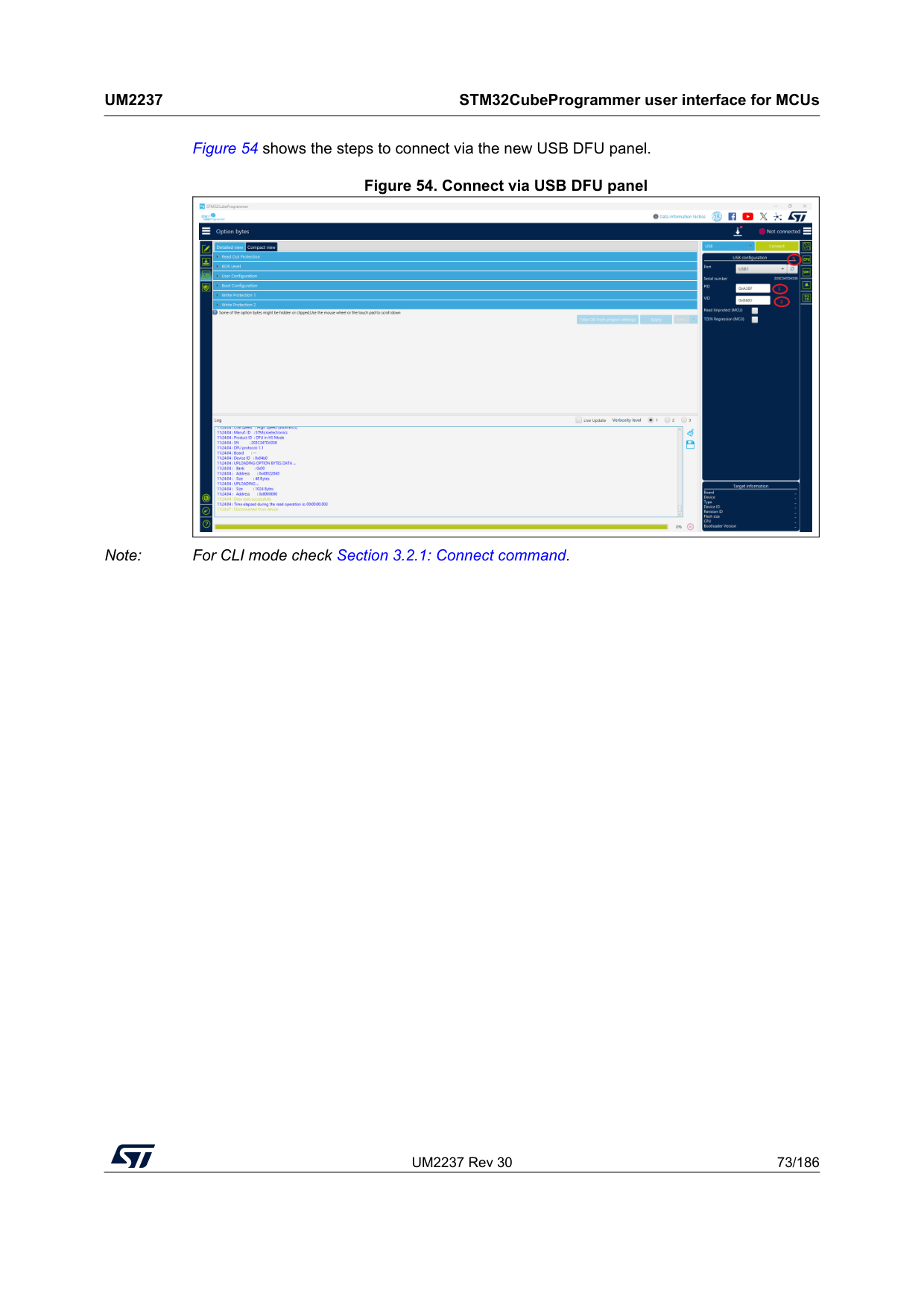
UM2237 Rev 30 73/186
Um2237
STM32CubeProgrammer user interface for MCUs 185 Figure 54 shows the steps to connect via the new USB DFU panel. Figure 54. Connect via USB DFU panel Note: For CLI mode check Section 3.2.1: Connect command.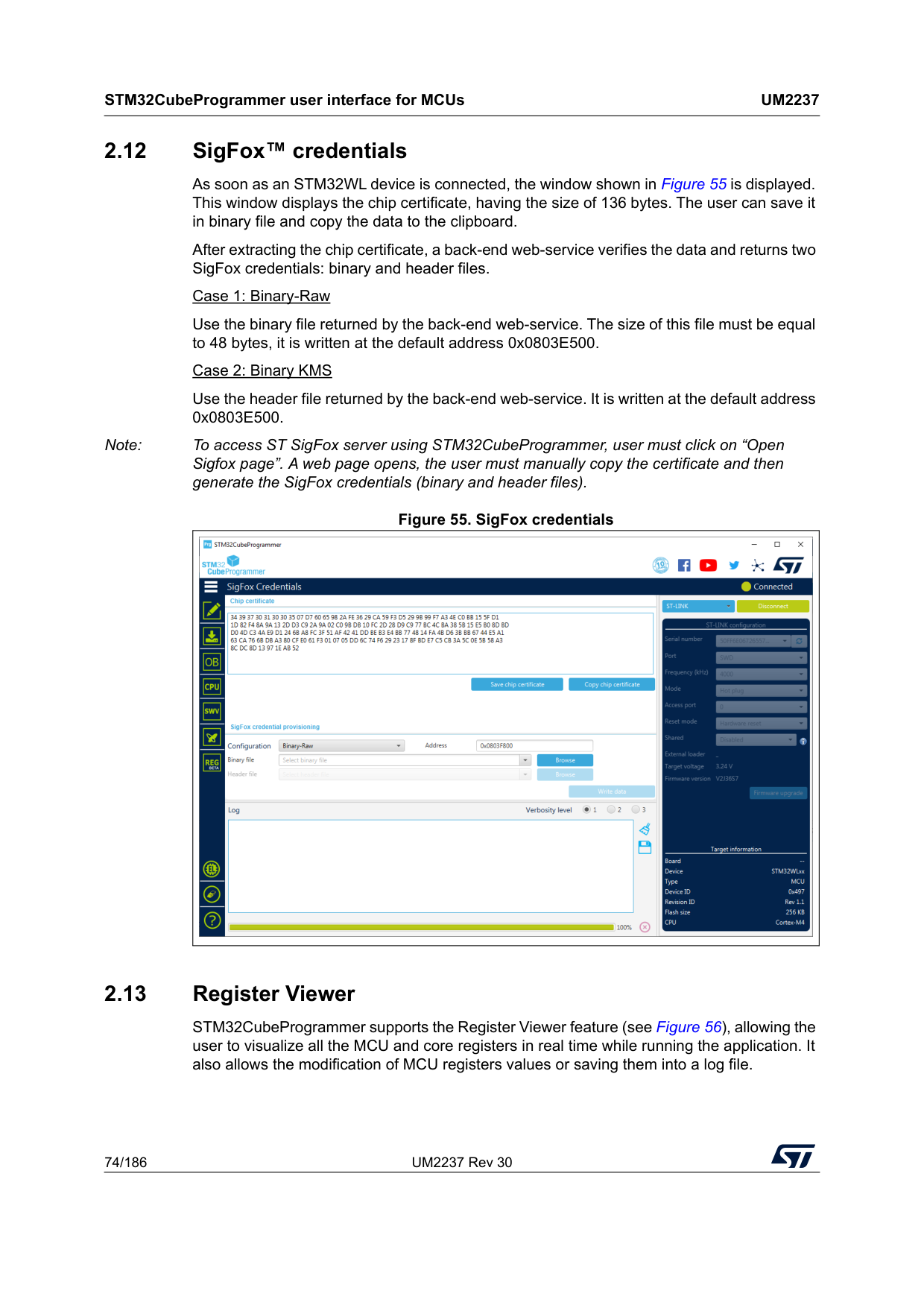
STM32CubeProgrammer user interface for MCUs
Um2237
74/186 UM2237 Rev 30 2.12 SigFox™ credentials As soon as an STM32WL device is connected, the window shown in Figure 55 is displayed. This window displays the chip certificate, having the size of 136 bytes. The user can save it in binary file and copy the data to the clipboard. After extracting the chip certificate, a back-end web-service verifies the data and returns two SigFox credentials: binary and header files. Case 1: Binary-Raw Use the binary file returned by the back-end web-service. The size of this file must be equal to 48 bytes, it is written at the default address 0x0803E500. Case 2: Binary KMS Use the header file returned by the back-end web-service. It is written at the default address 0x0803E500. Note: To access ST SigFox server using STM32CubeProgrammer, user must click on “Open Sigfox page”. A web page opens, the user must manually copy the certificate and then generate the SigFox credentials (binary and header files). Figure 55. SigFox credentials 2.13 Register Viewer STM32CubeProgrammer supports the Register Viewer feature (see Figure 56), allowing the user to visualize all the MCU and core registers in real time while running the application. It also allows the modification of MCU registers values or saving them into a log file.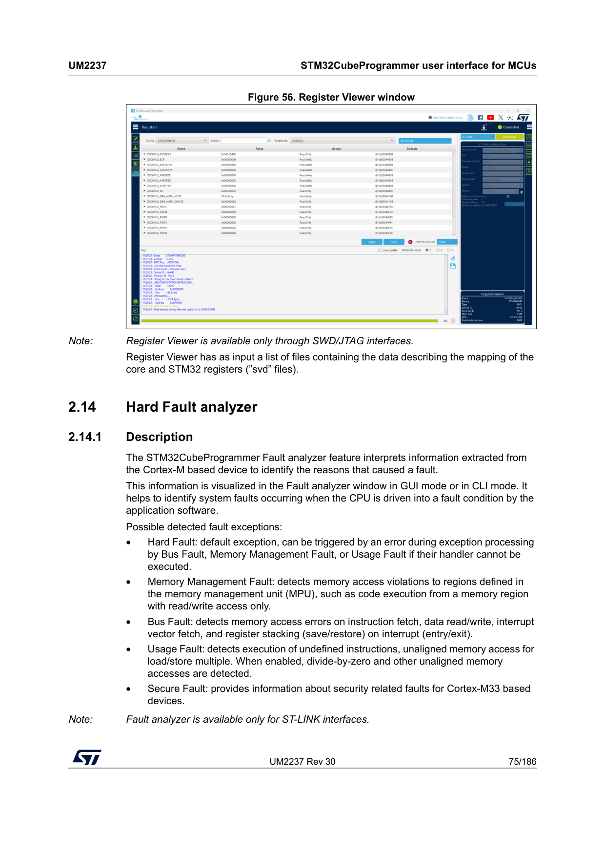
UM2237 Rev 30 75/186
Um2237
STM32CubeProgrammer user interface for MCUs 185 Figure 56. Register Viewer window Note: Register Viewer is available only through SWD/JTAG interfaces. Register Viewer has as input a list of files containing the data describing the mapping of the core and STM32 registers (”svd” files). 2.14 Hard Fault analyzer 2.14.1 Description The STM32CubeProgrammer Fault analyzer feature interprets information extracted from the Cortex-M based device to identify the reasons that caused a fault. This information is visualized in the Fault analyzer window in GUI mode or in CLI mode. It helps to identify system faults occurring when the CPU is driven into a fault condition by the application software. Possible detected fault exceptions: • Hard Fault: default exception, can be triggered by an error during exception processing by Bus Fault, Memory Management Fault, or Usage Fault if their handler cannot be executed. • Memory Management Fault: detects memory access violations to regions defined in the memory management unit (MPU), such as code execution from a memory region with read/write access only. • Bus Fault: detects memory access errors on instruction fetch, data read/write, interrupt vector fetch, and register stacking (save/restore) on interrupt (entry/exit). • Usage Fault: detects execution of undefined instructions, unaligned memory access for load/store multiple. When enabled, divide-by-zero and other unaligned memory accesses are detected. • Secure Fault: provides information about security related faults for Cortex-M33 based devices. Note: Fault analyzer is available only for ST-LINK interfaces.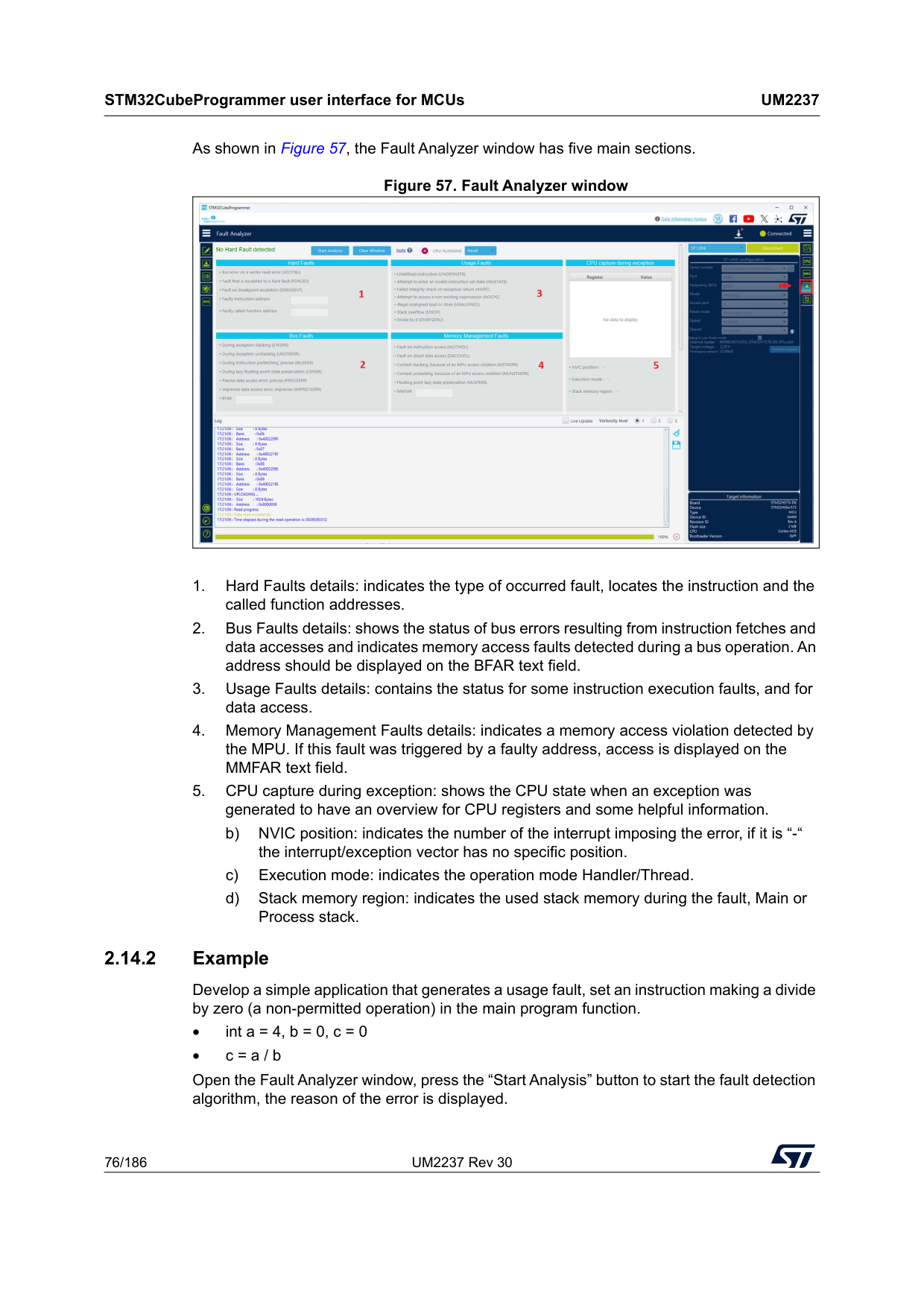
STM32CubeProgrammer user interface for MCUs
Um2237
76/186 UM2237 Rev 30 As shown in Figure 57, the Fault Analyzer window has five main sections. Figure 57. Fault Analyzer window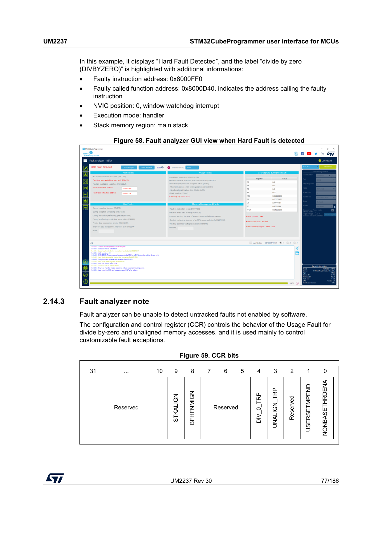
UM2237 Rev 30 77/186
Um2237
STM32CubeProgrammer user interface for MCUs 185 In this example, it displays “Hard Fault Detected”, and the label “divide by zero (DIVBYZERO)” is highlighted with additional informations: • Faulty instruction address: 0x8000FF0 • Faulty called function address: 0x8000D40, indicates the address calling the faulty instruction • NVIC position: 0, window watchdog interrupt • Execution mode: handler • Stack memory region: main stack Figure 58. Fault analyzer GUI view when Hard Fault is detected 2.14.3 Fault analyzer note Fault analyzer can be unable to detect untracked faults not enabled by software. The configuration and control register (CCR) controls the behavior of the Usage Fault for divide by-zero and unaligned memory accesses, and it is used mainly to control customizable fault exceptions.Figure 59. CCR bits 31 ... 10 9 8 7 6 5 4 3 2 1 0 Reserved
Stkalign
Bfhfnmign
ReservedDiv_0_Trp
Unalign_Trp
ReservedUsersetmpend
Nonbasethrdena
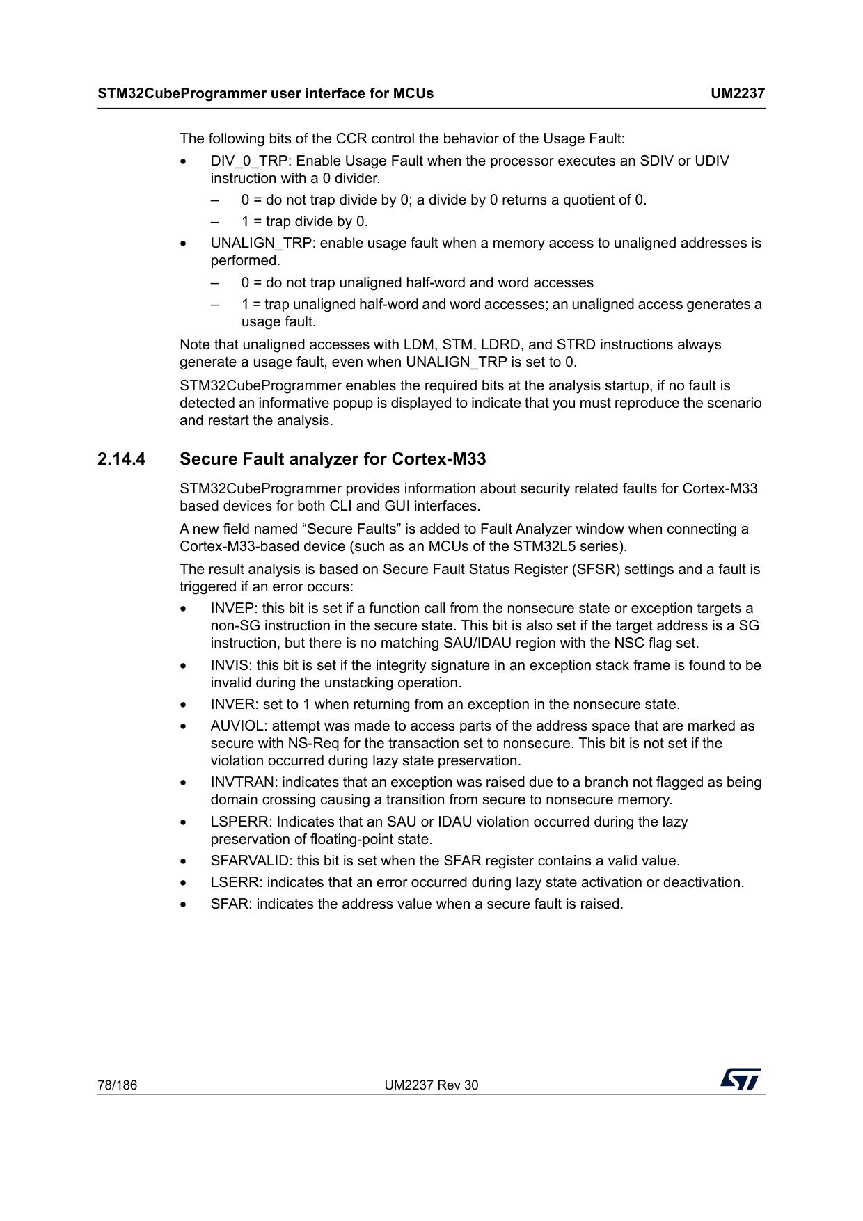
STM32CubeProgrammer user interface for MCUs
Um2237
78/186 UM2237 Rev 30 The following bits of the CCR control the behavior of the Usage Fault: • DIV_0_TRP: Enable Usage Fault when the processor executes an SDIV or UDIV instruction with a 0 divider. – 0 = do not trap divide by 0; a divide by 0 returns a quotient of 0. – 1 = trap divide by 0. • UNALIGN_TRP: enable usage fault when a memory access to unaligned addresses is performed. – 0 = do not trap unaligned half-word and word accesses – 1 = trap unaligned half-word and word accesses; an unaligned access generates a usage fault. Note that unaligned accesses with LDM, STM, LDRD, and STRD instructions always generate a usage fault, even when UNALIGN_TRP is set to 0. STM32CubeProgrammer enables the required bits at the analysis startup, if no fault is detected an informative popup is displayed to indicate that you must reproduce the scenario and restart the analysis. 2.14.4 Secure Fault analyzer for Cortex-M33 STM32CubeProgrammer provides information about security related faults for Cortex-M33 based devices for both CLI and GUI interfaces. A new field named “Secure Faults” is added to Fault Analyzer window when connecting a Cortex-M33-based device (such as an MCUs of the STM32L5 series). The result analysis is based on Secure Fault Status Register (SFSR) settings and a fault is triggered if an error occurs: • INVEP: this bit is set if a function call from the nonsecure state or exception targets a non-SG instruction in the secure state. This bit is also set if the target address is a SG instruction, but there is no matching SAU/IDAU region with the NSC flag set. • INVIS: this bit is set if the integrity signature in an exception stack frame is found to be invalid during the unstacking operation. • INVER: set to 1 when returning from an exception in the nonsecure state. • AUVIOL: attempt was made to access parts of the address space that are marked as secure with NS-Req for the transaction set to nonsecure. This bit is not set if the violation occurred during lazy state preservation. • INVTRAN: indicates that an exception was raised due to a branch not flagged as being domain crossing causing a transition from secure to nonsecure memory. • LSPERR: Indicates that an SAU or IDAU violation occurred during the lazy preservation of floating-point state. • SFARVALID: this bit is set when the SFAR register contains a valid value. • LSERR: indicates that an error occurred during lazy state activation or deactivation. • SFAR: indicates the address value when a secure fault is raised.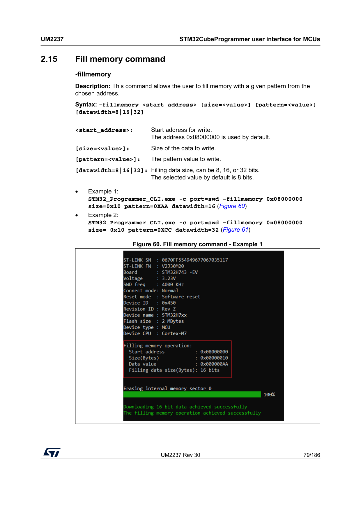
UM2237 Rev 30 79/186
Um2237
STM32CubeProgrammer user interface for MCUs 185 2.15 Fill memory command -fillmemory Description: This command allows the user to fill memory with a given pattern from the chosen address. Syntax: -fillmemory• Example 1: STM32_Programmer_CLI.exe -c port=swd -fillmemory 0x08000000 size=0x10 pattern=0XAA datawidth=16 (Figure 60) • Example 2: STM32_Programmer_CLI.exe -c port=swd -fillmemory 0x08000000 size= 0x10 pattern=0XCC datawidth=32 (Figure 61) Figure 60. Fill memory command - Example 1
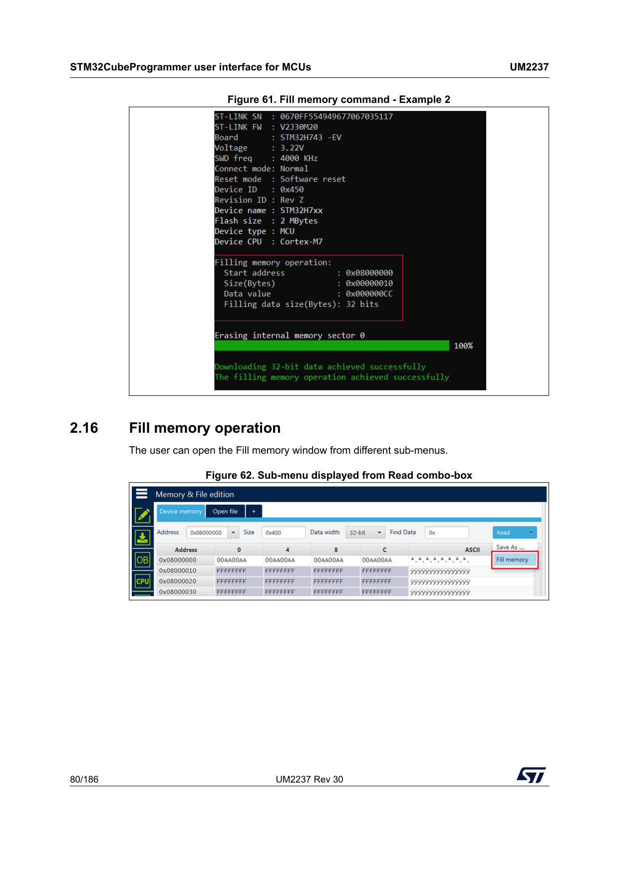
STM32CubeProgrammer user interface for MCUs
Um2237
80/186 UM2237 Rev 30 Figure 61. Fill memory command - Example 2 2.16 Fill memory operation The user can open the Fill memory window from different sub-menus. Figure 62. Sub-menu displayed from Read combo-box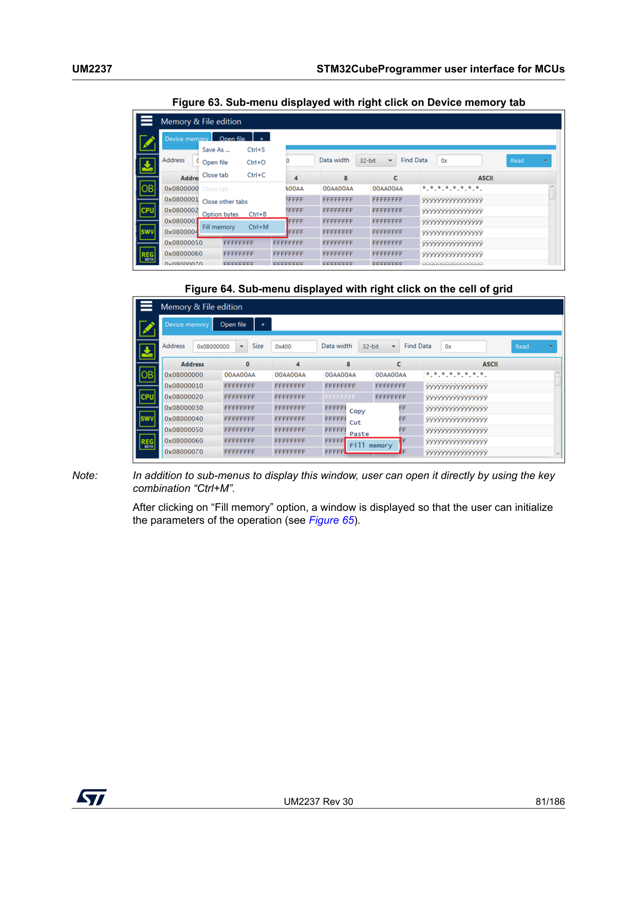
UM2237 Rev 30 81/186
Um2237
STM32CubeProgrammer user interface for MCUs 185 Figure 63. Sub-menu displayed with right click on Device memory tab Figure 64. Sub-menu displayed with right click on the cell of grid Note: In addition to sub-menus to display this window, user can open it directly by using the key combination “Ctrl+M”. After clicking on “Fill memory” option, a window is displayed so that the user can initialize the parameters of the operation (see Figure 65).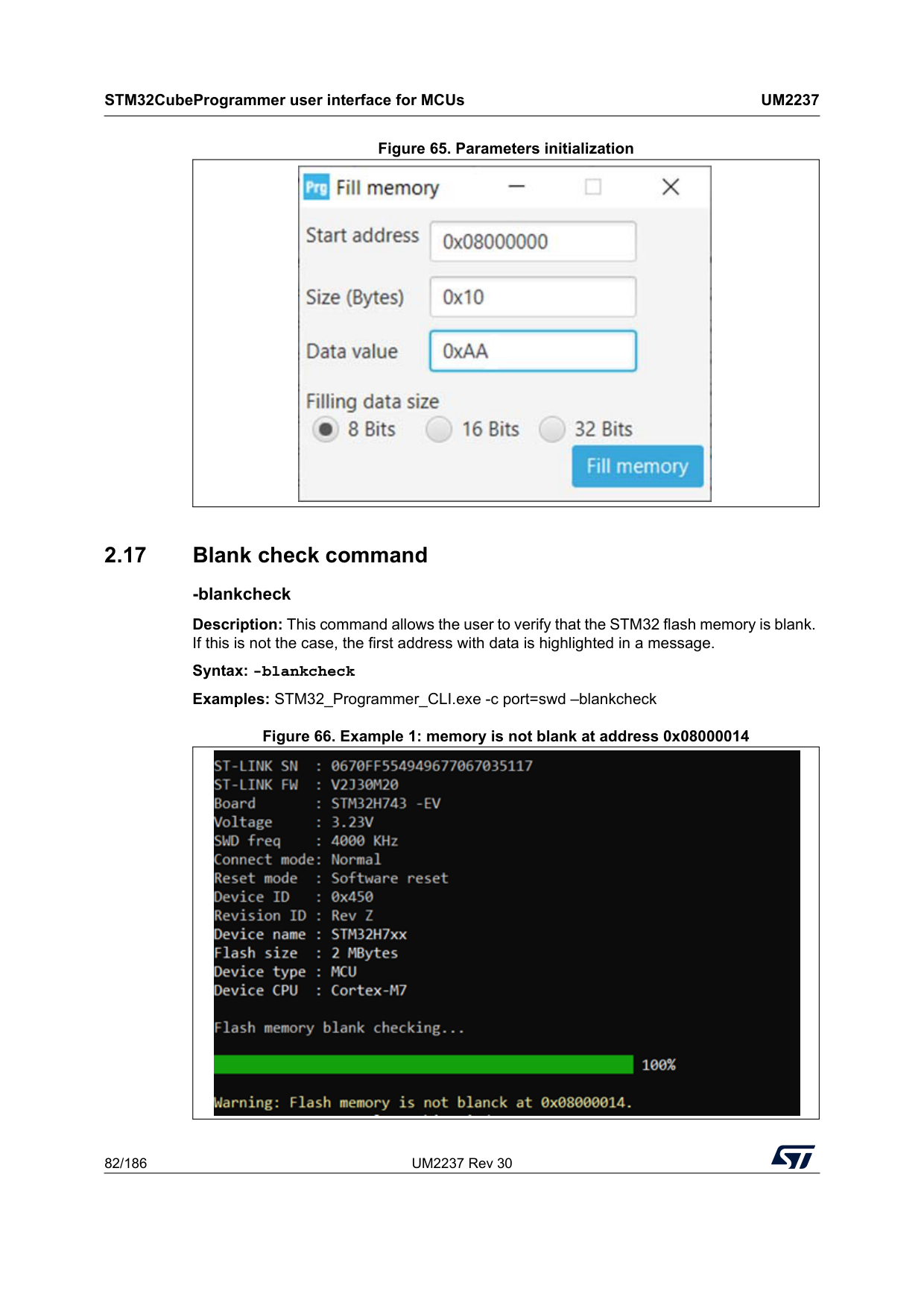
STM32CubeProgrammer user interface for MCUs
Um2237
82/186 UM2237 Rev 30 Figure 65. Parameters initialization 2.17 Blank check command -blankcheck Description: This command allows the user to verify that the STM32 flash memory is blank. If this is not the case, the first address with data is highlighted in a message. Syntax: -blankcheck Examples: STM32_Programmer_CLI.exe -c port=swd –blankcheck Figure 66. Example 1: memory is not blank at address 0x08000014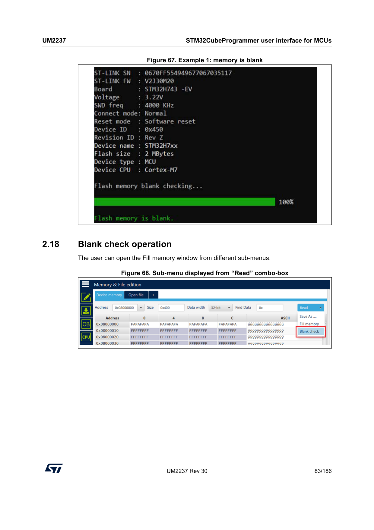
UM2237 Rev 30 83/186
Um2237
STM32CubeProgrammer user interface for MCUs 185 Figure 67. Example 1: memory is blank 2.18 Blank check operation The user can open the Fill memory window from different sub-menus. Figure 68. Sub-menu displayed from “Read” combo-box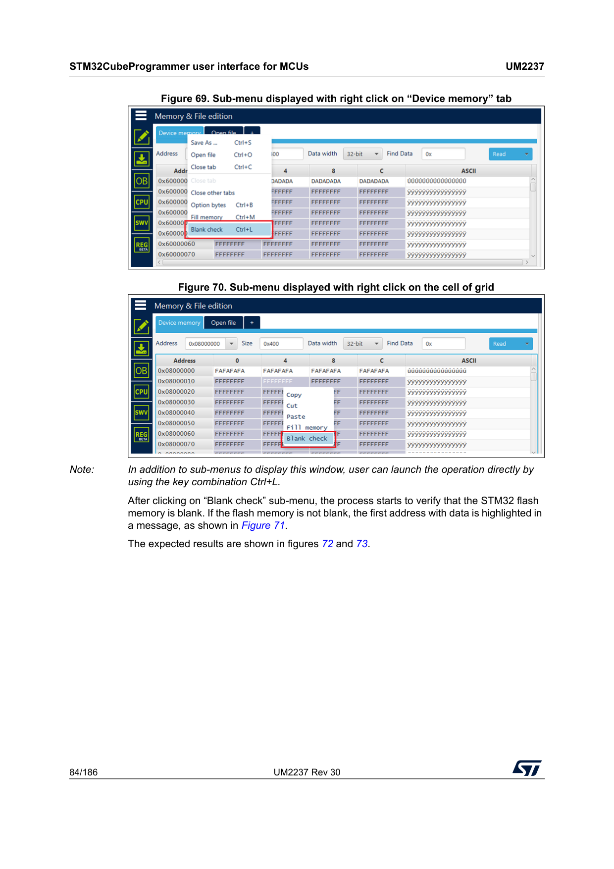
STM32CubeProgrammer user interface for MCUs
Um2237
84/186 UM2237 Rev 30 Figure 69. Sub-menu displayed with right click on “Device memory” tab Figure 70. Sub-menu displayed with right click on the cell of grid Note: In addition to sub-menus to display this window, user can launch the operation directly by using the key combination Ctrl+L. After clicking on “Blank check” sub-menu, the process starts to verify that the STM32 flash memory is blank. If the flash memory is not blank, the first address with data is highlighted in a message, as shown in Figure 71. The expected results are shown in figures 72 and 73.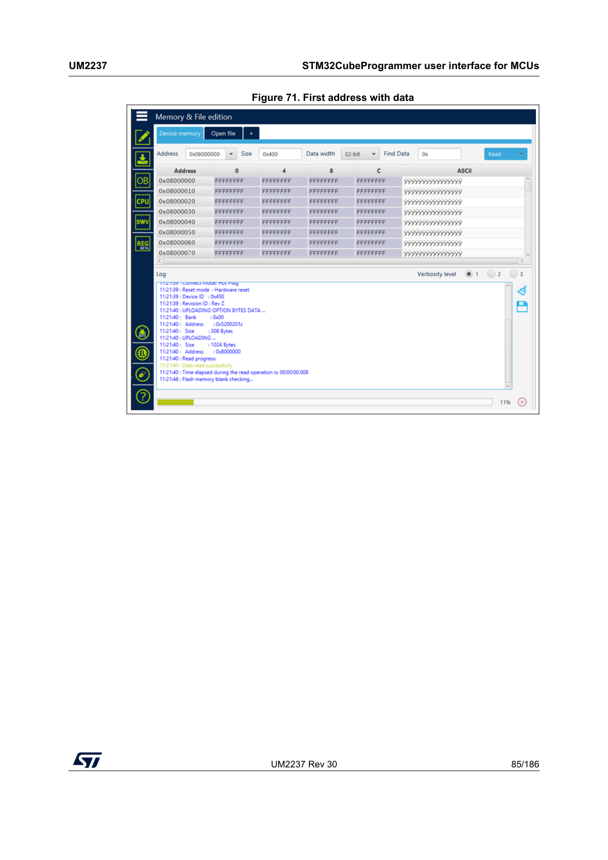
UM2237 Rev 30 85/186
Um2237
STM32CubeProgrammer user interface for MCUs 185 Figure 71. First address with data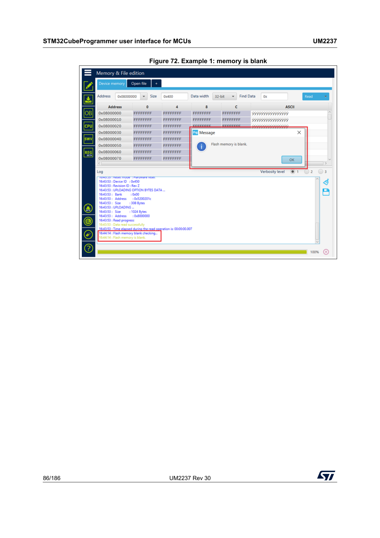
STM32CubeProgrammer user interface for MCUs
Um2237
86/186 UM2237 Rev 30 Figure 72. Example 1: memory is blank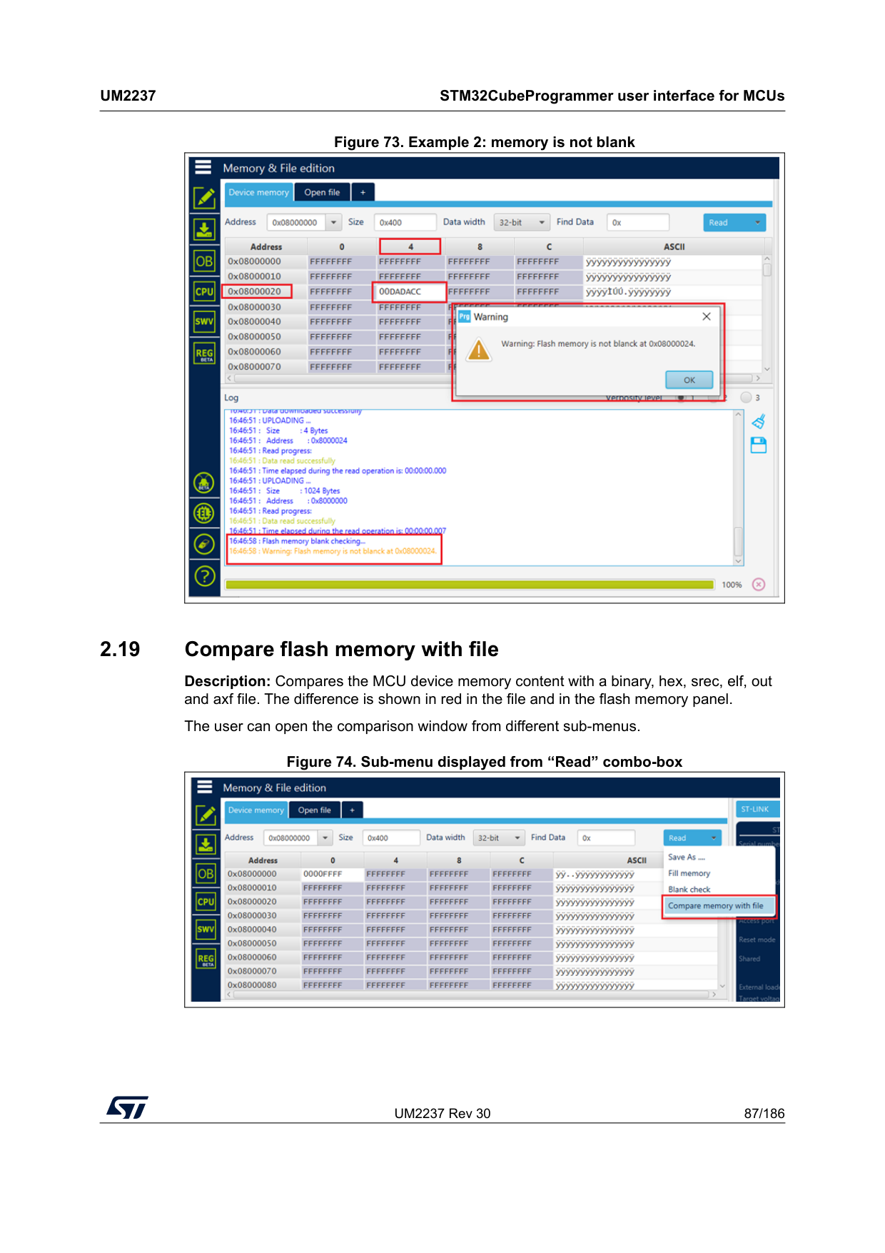
UM2237 Rev 30 87/186
Um2237
STM32CubeProgrammer user interface for MCUs 185 Figure 73. Example 2: memory is not blank 2.19 Compare flash memory with file Description: Compares the MCU device memory content with a binary, hex, srec, elf, out and axf file. The difference is shown in red in the file and in the flash memory panel. The user can open the comparison window from different sub-menus. Figure 74. Sub-menu displayed from “Read” combo-box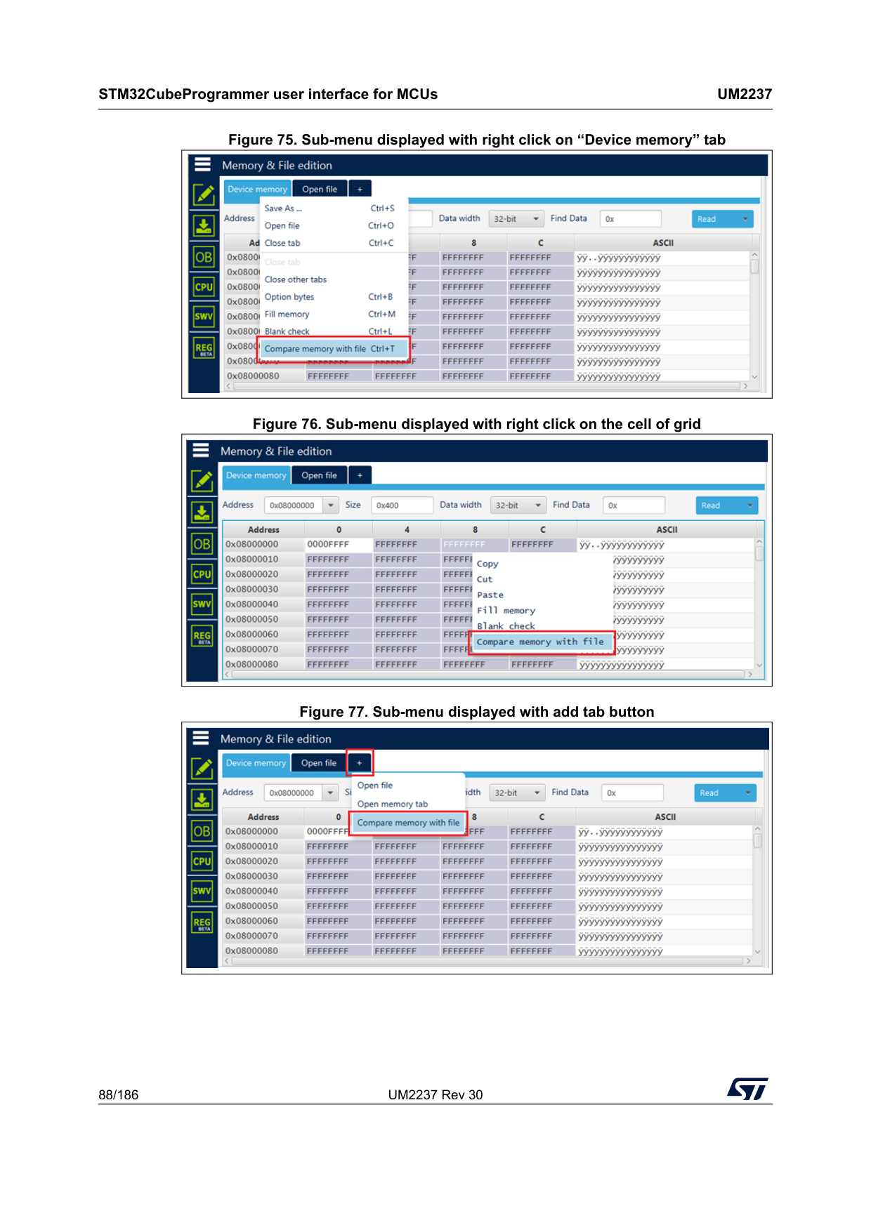
STM32CubeProgrammer user interface for MCUs
Um2237
88/186 UM2237 Rev 30 Figure 75. Sub-menu displayed with right click on “Device memory” tab Figure 76. Sub-menu displayed with right click on the cell of grid Figure 77. Sub-menu displayed with add tab button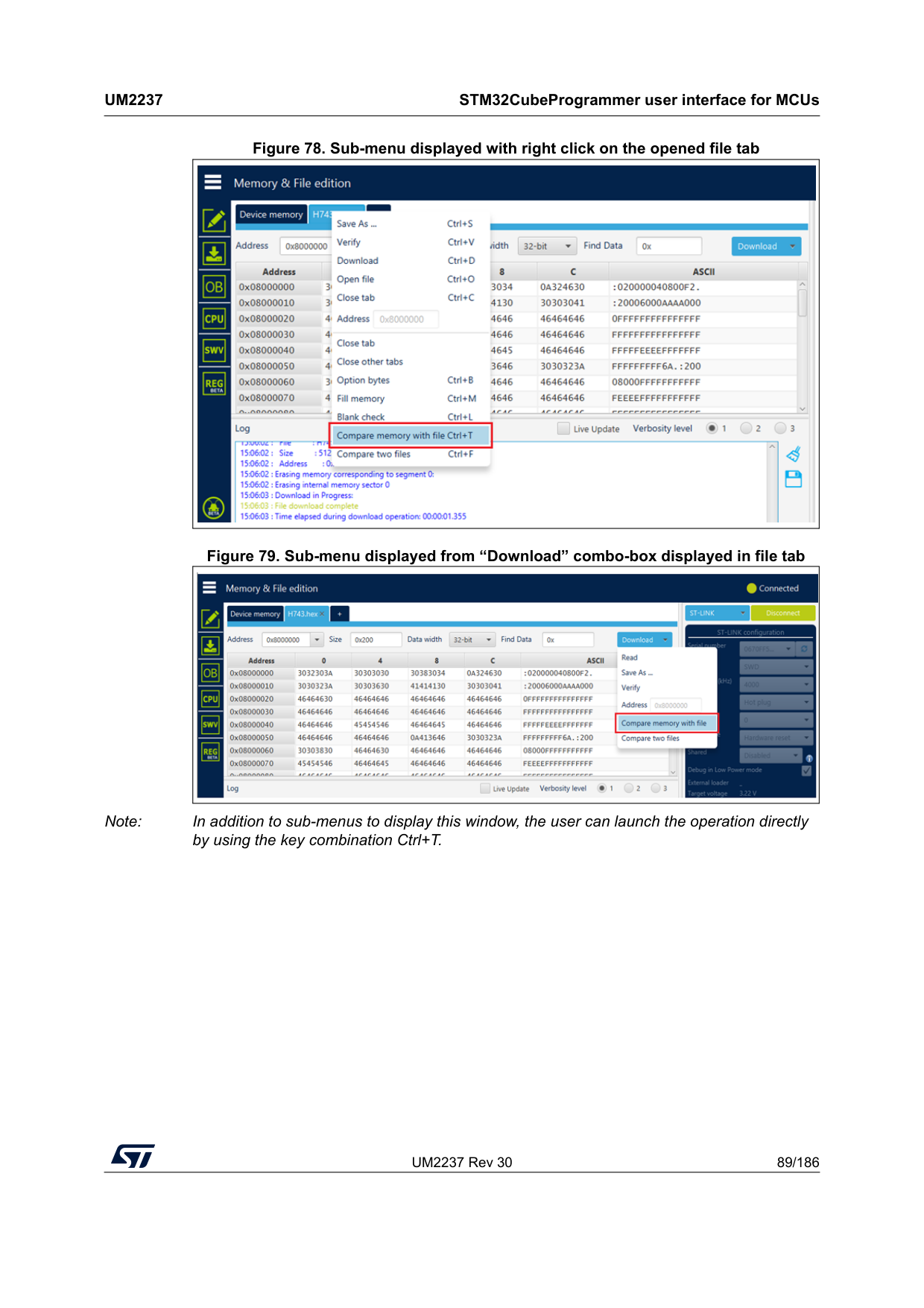
UM2237 Rev 30 89/186
Um2237
STM32CubeProgrammer user interface for MCUs 185 Figure 78. Sub-menu displayed with right click on the opened file tab Figure 79. Sub-menu displayed from “Download” combo-box displayed in file tab Note: In addition to sub-menus to display this window, the user can launch the operation directly by using the key combination Ctrl+T.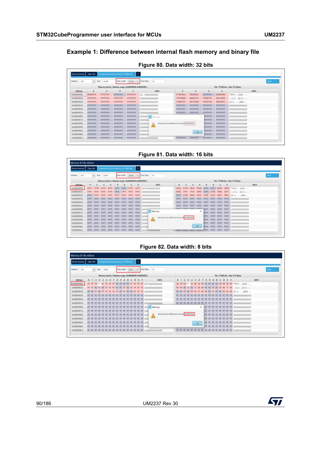
STM32CubeProgrammer user interface for MCUs
Um2237
90/186 UM2237 Rev 30 Example 1: Difference between internal flash memory and binary file Figure 80. Data width: 32 bits Figure 81. Data width: 16 bits Figure 82. Data width: 8 bits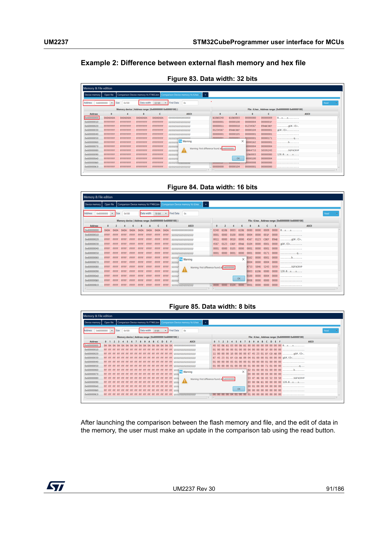
UM2237 Rev 30 91/186
Um2237
STM32CubeProgrammer user interface for MCUs 185 Example 2: Difference between external flash memory and hex file Figure 83. Data width: 32 bits Figure 84. Data width: 16 bits Figure 85. Data width: 8 bits After launching the comparison between the flash memory and file, and the edit of data in the memory, the user must make an update in the comparison tab using the read button.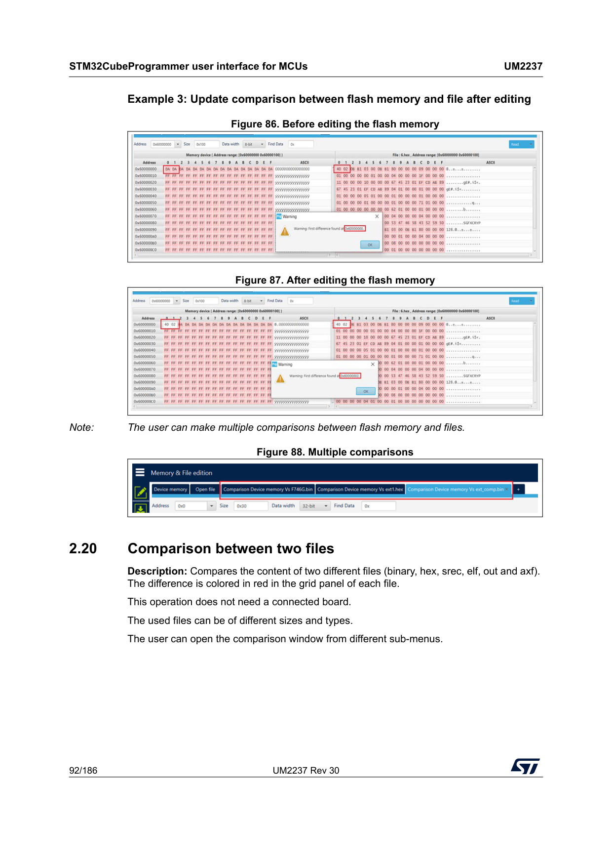
STM32CubeProgrammer user interface for MCUs
Um2237
92/186 UM2237 Rev 30 Example 3: Update comparison between flash memory and file after editing Figure 86. Before editing the flash memory Figure 87. After editing the flash memory Note: The user can make multiple comparisons between flash memory and files. Figure 88. Multiple comparisons 2.20 Comparison between two files Description: Compares the content of two different files (binary, hex, srec, elf, out and axf). The difference is colored in red in the grid panel of each file. This operation does not need a connected board. The used files can be of different sizes and types. The user can open the comparison window from different sub-menus.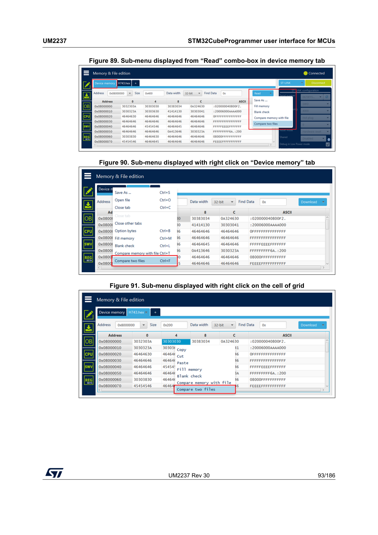
UM2237 Rev 30 93/186
Um2237
STM32CubeProgrammer user interface for MCUs 185 Figure 89. Sub-menu displayed from “Read” combo-box in device memory tab Figure 90. Sub-menu displayed with right click on “Device memory” tab Figure 91. Sub-menu displayed with right click on the cell of grid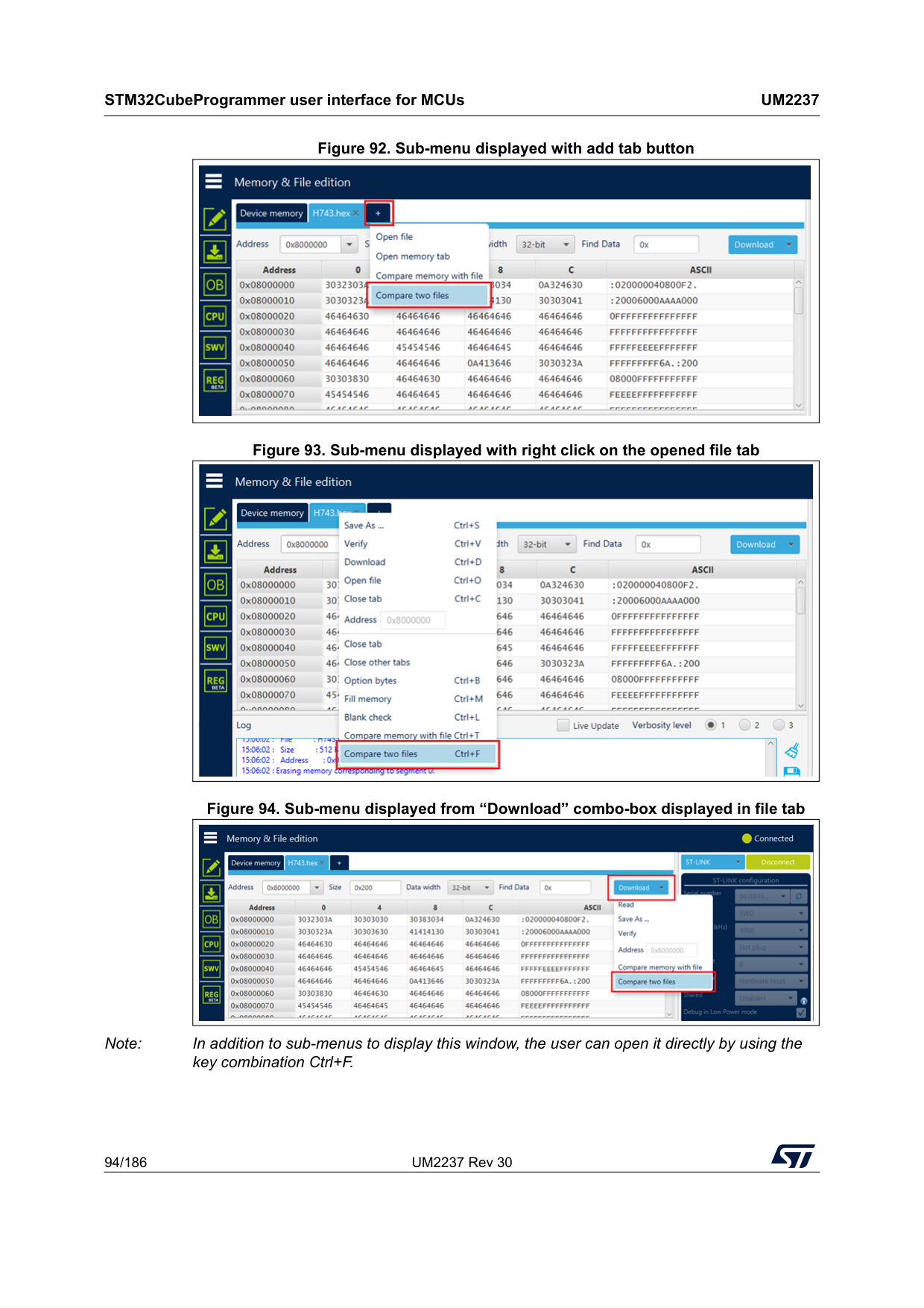
STM32CubeProgrammer user interface for MCUs
Um2237
94/186 UM2237 Rev 30 Figure 92. Sub-menu displayed with add tab button Figure 93. Sub-menu displayed with right click on the opened file tab Figure 94. Sub-menu displayed from “Download” combo-box displayed in file tab Note: In addition to sub-menus to display this window, the user can open it directly by using the key combination Ctrl+F.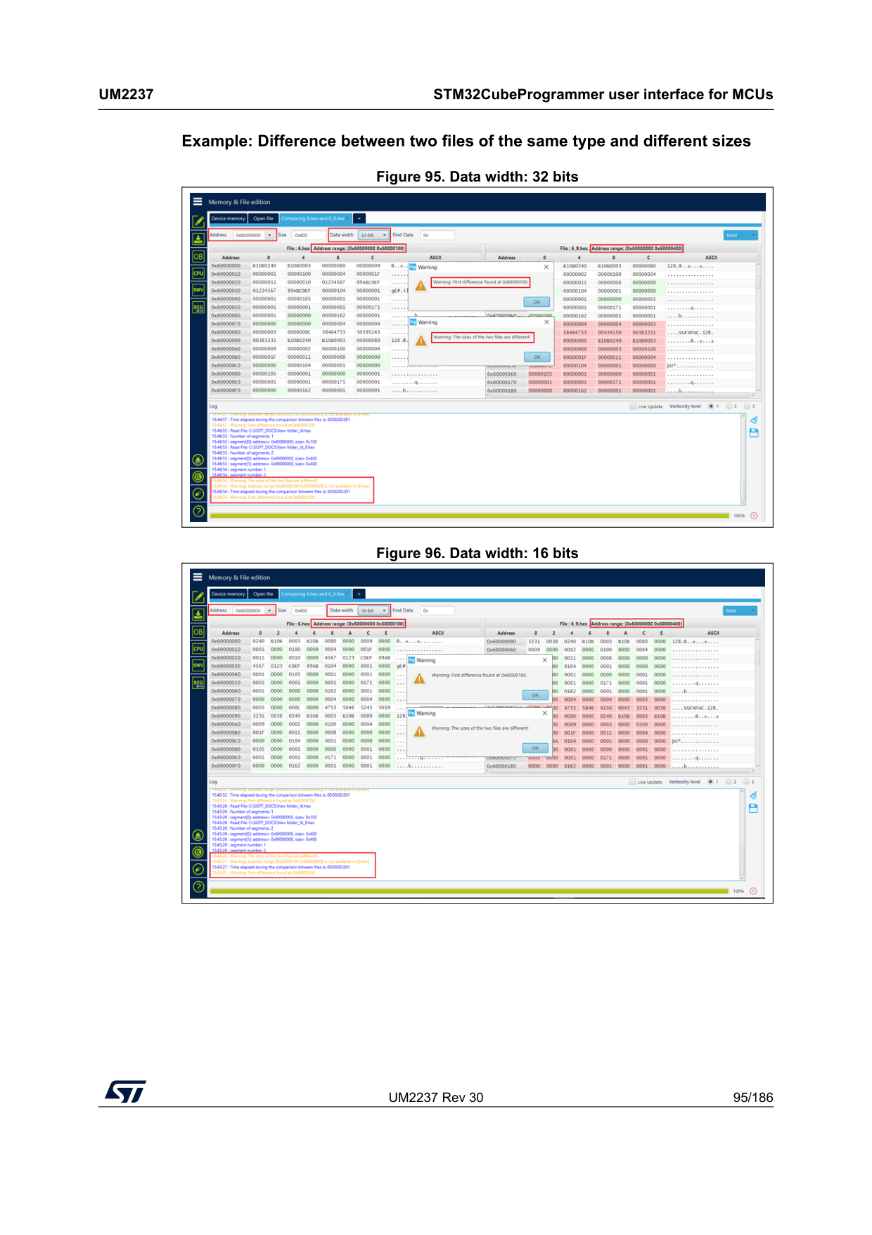
UM2237 Rev 30 95/186
Um2237
STM32CubeProgrammer user interface for MCUs 185 Example: Difference between two files of the same type and different sizes Figure 95. Data width: 32 bits Figure 96. Data width: 16 bits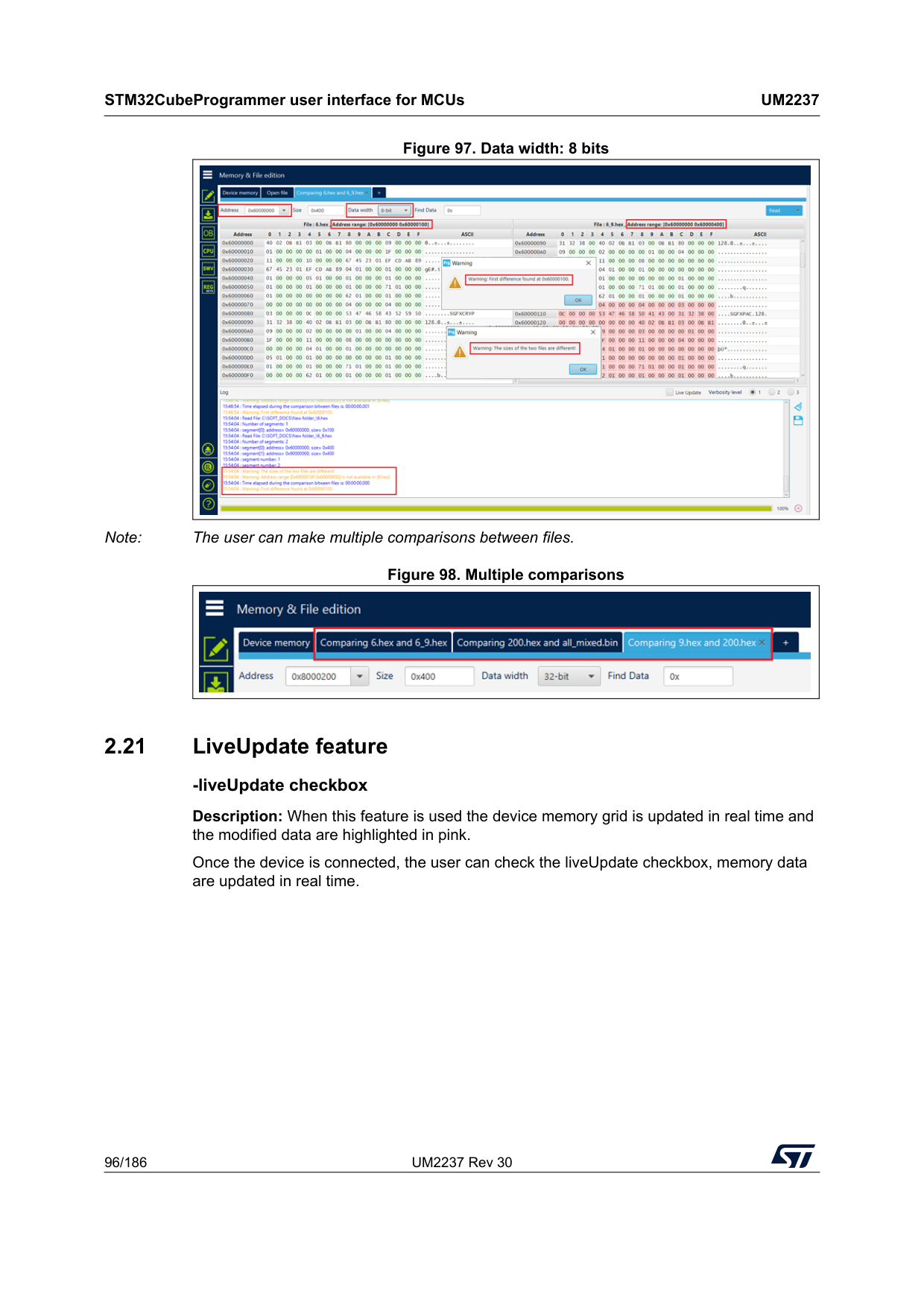
STM32CubeProgrammer user interface for MCUs
Um2237
96/186 UM2237 Rev 30 Figure 97. Data width: 8 bits Note: The user can make multiple comparisons between files. Figure 98. Multiple comparisons 2.21 LiveUpdate feature -liveUpdate checkbox Description: When this feature is used the device memory grid is updated in real time and the modified data are highlighted in pink. Once the device is connected, the user can check the liveUpdate checkbox, memory data are updated in real time.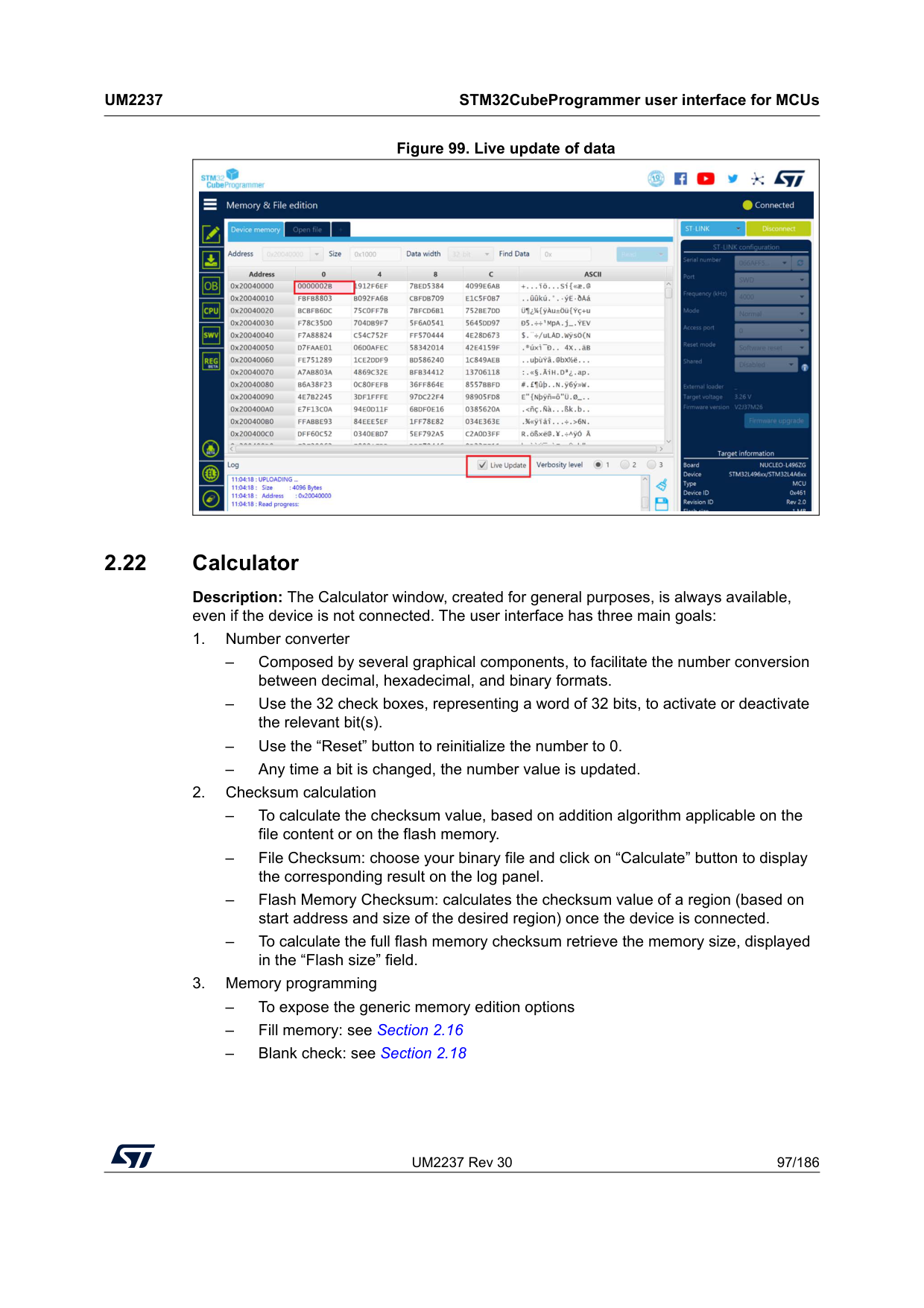
UM2237 Rev 30 97/186
Um2237
STM32CubeProgrammer user interface for MCUs 185 Figure 99. Live update of data 2.22 Calculator Description: The Calculator window, created for general purposes, is always available, even if the device is not connected. The user interface has three main goals: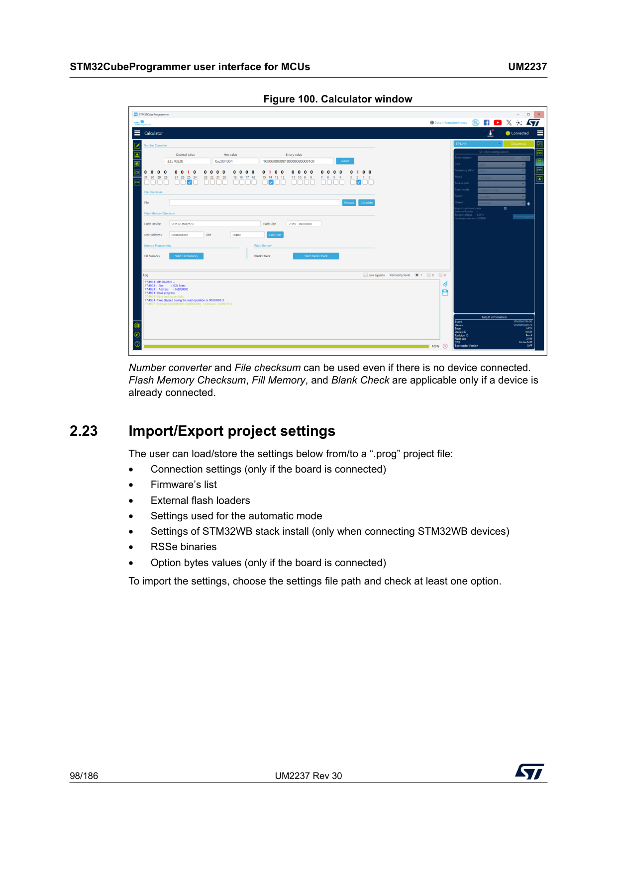
STM32CubeProgrammer user interface for MCUs
Um2237
98/186 UM2237 Rev 30 Figure 100. Calculator window Number converter and File checksum can be used even if there is no device connected. Flash Memory Checksum, Fill Memory, and Blank Check are applicable only if a device is already connected. 2.23 Import/Export project settings The user can load/store the settings below from/to a “.prog” project file: • Connection settings (only if the board is connected) • Firmware’s list • External flash loaders • Settings used for the automatic mode • Settings of STM32WB stack install (only when connecting STM32WB devices) • RSSe binaries • Option bytes values (only if the board is connected) To import the settings, choose the settings file path and check at least one option.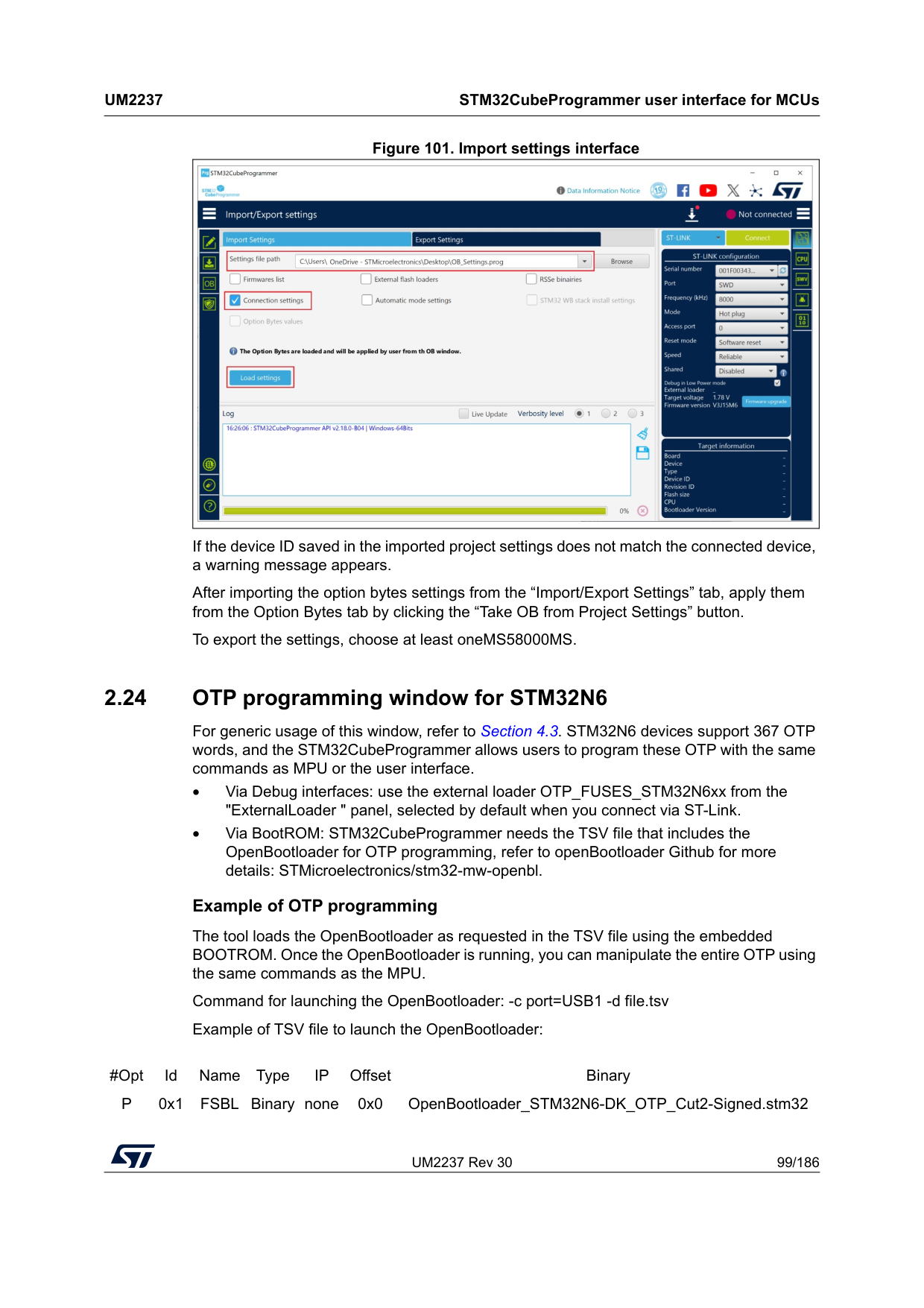
UM2237 Rev 30 99/186
Um2237
STM32CubeProgrammer user interface for MCUs 185 Figure 101. Import settings interface If the device ID saved in the imported project settings does not match the connected device, a warning message appears. After importing the option bytes settings from the “Import/Export Settings” tab, apply them from the Option Bytes tab by clicking the “Take OB from Project Settings” button. To export the settings, choose at least oneMS58000MS. 2.24 OTP programming window for STM32N6 For generic usage of this window, refer to Section 4.3. STM32N6 devices support 367 OTP words, and the STM32CubeProgrammer allows users to program these OTP with the same commands as MPU or the user interface. • Via Debug interfaces: use the external loader OTP_FUSES_STM32N6xx from the "ExternalLoader " panel, selected by default when you connect via ST-Link. • Via BootROM: STM32CubeProgrammer needs the TSV file that includes the OpenBootloader for OTP programming, refer to openBootloader Github for more details: STMicroelectronics/stm32-mw-openbl. Example of OTP programming The tool loads the OpenBootloader as requested in the TSV file using the embedded BOOTROM. Once the OpenBootloader is running, you can manipulate the entire OTP using the same commands as the MPU. Command for launching the OpenBootloader: -c port=USB1 -d file.tsv Example of TSV file to launch the OpenBootloader:#Opt Id Name Type
Ip
Offset BinaryP
0x1 FSBL Binary none 0x0 OpenBootloader_STM32N6-DK_OTP_Cut2-Signed.stm32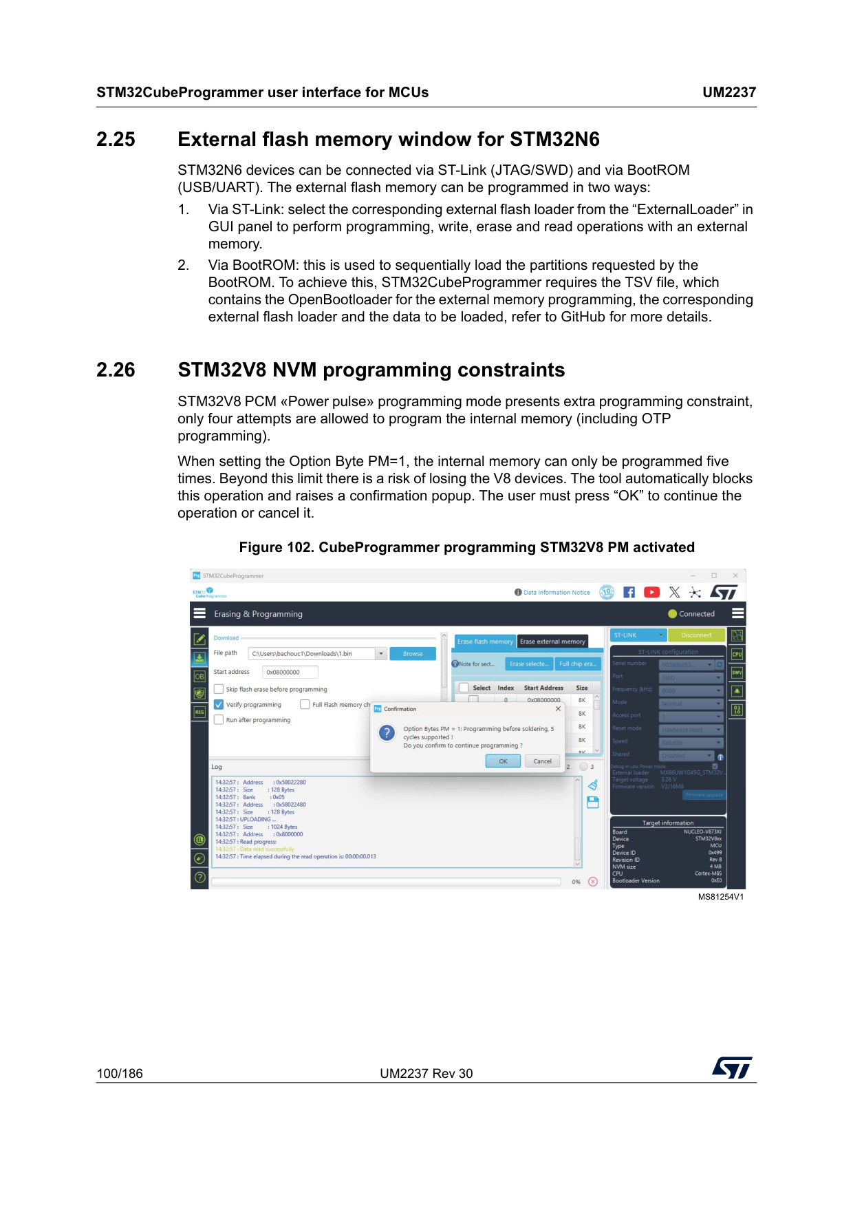
STM32CubeProgrammer user interface for MCUs
Um2237
100/186 UM2237 Rev 30 2.25 External flash memory window for STM32N6 STM32N6 devices can be connected via ST-Link (JTAG/SWD) and via BootROM (USB/UART). The external flash memory can be programmed in two ways:Ms81254V1
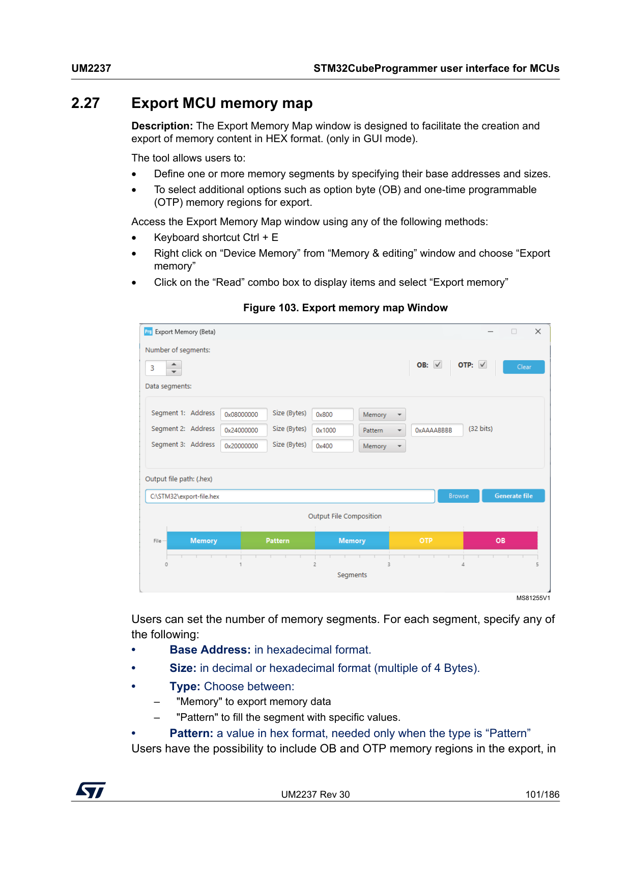
UM2237 Rev 30 101/186
Um2237
STM32CubeProgrammer user interface for MCUs 185 2.27 Export MCU memory map Description: The Export Memory Map window is designed to facilitate the creation and export of memory content in HEX format. (only in GUI mode). The tool allows users to: • Define one or more memory segments by specifying their base addresses and sizes. • To select additional options such as option byte (OB) and one-time programmable (OTP) memory regions for export. Access the Export Memory Map window using any of the following methods: • Keyboard shortcut Ctrl + E • Right click on “Device Memory” from “Memory & editing” window and choose “Export memory” • Click on the “Read” combo box to display items and select “Export memory” Figure 103. Export memory map Window Users can set the number of memory segments. For each segment, specify any of the following: • Base Address: in hexadecimal format. • Size: in decimal or hexadecimal format (multiple of 4 Bytes). • Type: Choose between: – "Memory" to export memory data – "Pattern" to fill the segment with specific values. • Pattern: a value in hex format, needed only when the type is “Pattern” Users have the possibility to include OB and OTP memory regions in the export, inMs81255V1
STM32CubeProgrammer user interface for MCUs
Um2237
102/186 UM2237 Rev 30 addition to the user defined segments. The Clear button allows users to quickly reset the export memory map data to its default state. The output path for the HEX file can be specified manually or selected using a file browser dialog. Note: When OB is selected, the export process may include multiple segments corresponding to the option bytes defined by the current device configuration. The number of these OB segments depends on the specific device and its configuration. Each OB segment is exported as a separate segment in the HEX file, ensuring that all relevant option byte data are included. Note: The tool prevents data corruption and ensures that each memory segment occupies a unique, non-overlapping region in the exported file. If any overlap is detected, the export process is stopped, and the user is notified with an error message indicating which segments are in conflict.
UM2237 Rev 30 103/186
Um2237
STM32CubeProgrammer command line interface (CLI) for MCUs 185 3 STM32CubeProgrammer command line interface (CLI) for MCUs 3.1 Command line usage The following sections describe how to use the STM32CubeProgrammer from the command line. To launch command line interface, call 3.2 Generic commands This section presents the set of commands supported by all STM32 MCUs. 3.2.1 Connect command -c, --connect Description: Establishes the connection to the device. This command allows the host to open the chosen device port (UART/USB/JTAG/SWD/JLINK/SPI/CAN/I2C). Syntax: -c port=• ST-LINK options
macOS x86_64: STM32CubeProgrammer.app/Contents/MacOs/bin/STM32_Programmer_CLI macOS aarch64: STM32CubeProgrammer.app/Contents/Resources/bin/STM32_Programmer_CLI Windows: ..\STMicroelectronics\STM32Cube\STM32CubeProgrammer\bin\STM32_Programmer_ CLI.exe Linux: ../STMicroelectronics/STM32Cube/STM32CubeProgrammer/bin/STM32_Programmer_
Cli
port=
STM32CubeProgrammer command line interface (CLI) for MCUs
Um2237
104/186 UM2237 Rev 30 Note: The entered frequency values are rounded to correspond to those supported by ST-LINK probe.HWrst Hardware reset. Performed by the STLink, which physically drives the NRST pin of the MCU. The NRST pin of the STLink must be connected to the MCU. SWrst Software reset (a system reset via Cortex registers) Crst Core reset (via Cortex registers) [index=Ur
The “Connect Under Reset” mode enables connection to the target using a reset vector catch before executing any instruction. This is useful in many cases, for example when the target contains a code that disables the JTAG/SWD pins. Hotplug
The “Hot Plug” mode enables connection to the target without a halt or reset. This is useful for updating the RAM addresses or the IP registers while the application is running. Powerdown
Allows to put the target in debug mode, even if the application has not started since the target power up. The hardware reset signal must be connected between ST-Link and the target. This feature might be not fully effective on some boards (MB1360, MB1319, MB1361, MB1355) with STMPS2141 power switch. hwRstPulse The tool generates a reset pulse and then connects to the target. This connection mode does not prevent application launch before connection. It is used in devices where under mode is not available, such as STM32WB0x and STM32WL33. [ap=
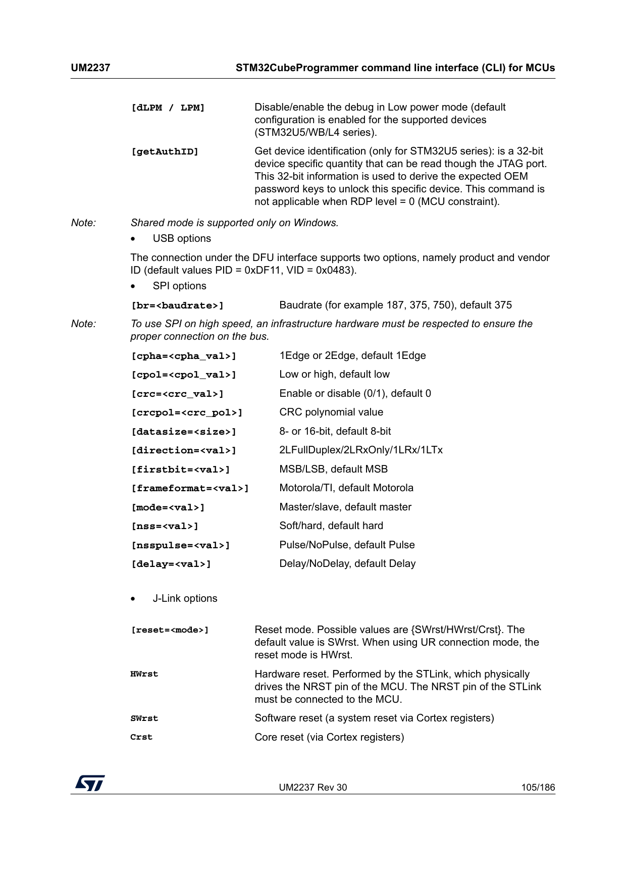
UM2237 Rev 30 105/186
Um2237
STM32CubeProgrammer command line interface (CLI) for MCUs 185 Note: Shared mode is supported only on Windows. • USB options The connection under the DFU interface supports two options, namely product and vendor ID (default values PID = 0xDF11, VID = 0x0483). • SPI options [br=[dLPM / LPM] Disable/enable the debug in Low power mode (default configuration is enabled for the supported devices (STM32U5/WB/L4 series). [getAuthID] Get device identification (only for STM32U5 series): is a 32-bit device specific quantity that can be read though the JTAG port. This 32-bit information is used to derive the expected OEM password keys to unlock this specific device. This command is not applicable when RDP level = 0 (MCU constraint). [reset=
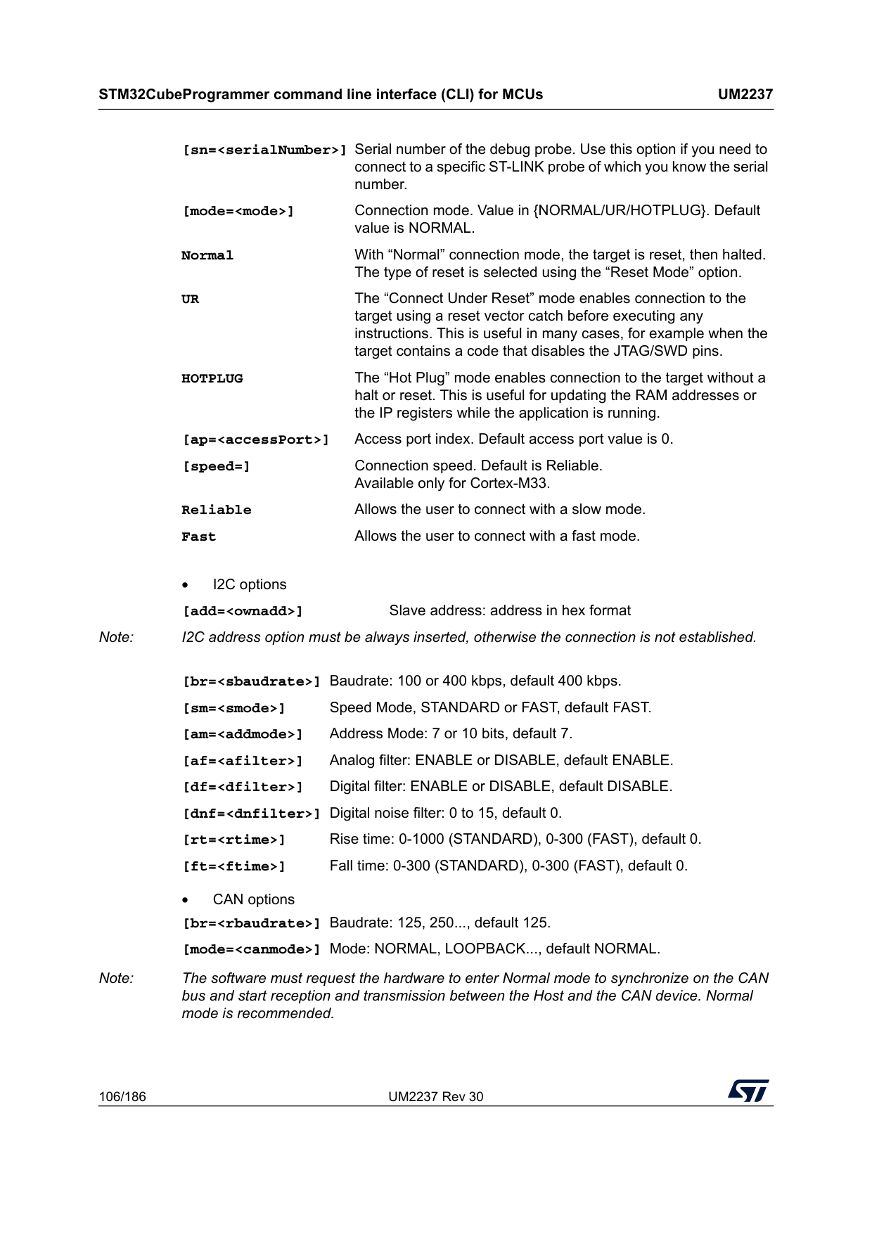
STM32CubeProgrammer command line interface (CLI) for MCUs
Um2237
106/186 UM2237 Rev 30 • I2C options [add=• CAN options Note: The software must request the hardware to enter Normal mode to synchronize on the CAN bus and start reception and transmission between the Host and the CAN device. Normal mode is recommended. [sn=Ur
The “Connect Under Reset” mode enables connection to the target using a reset vector catch before executing any instructions. This is useful in many cases, for example when the target contains a code that disables the JTAG/SWD pins. Hotplug
The “Hot Plug” mode enables connection to the target without a halt or reset. This is useful for updating the RAM addresses or the IP registers while the application is running. [ap=
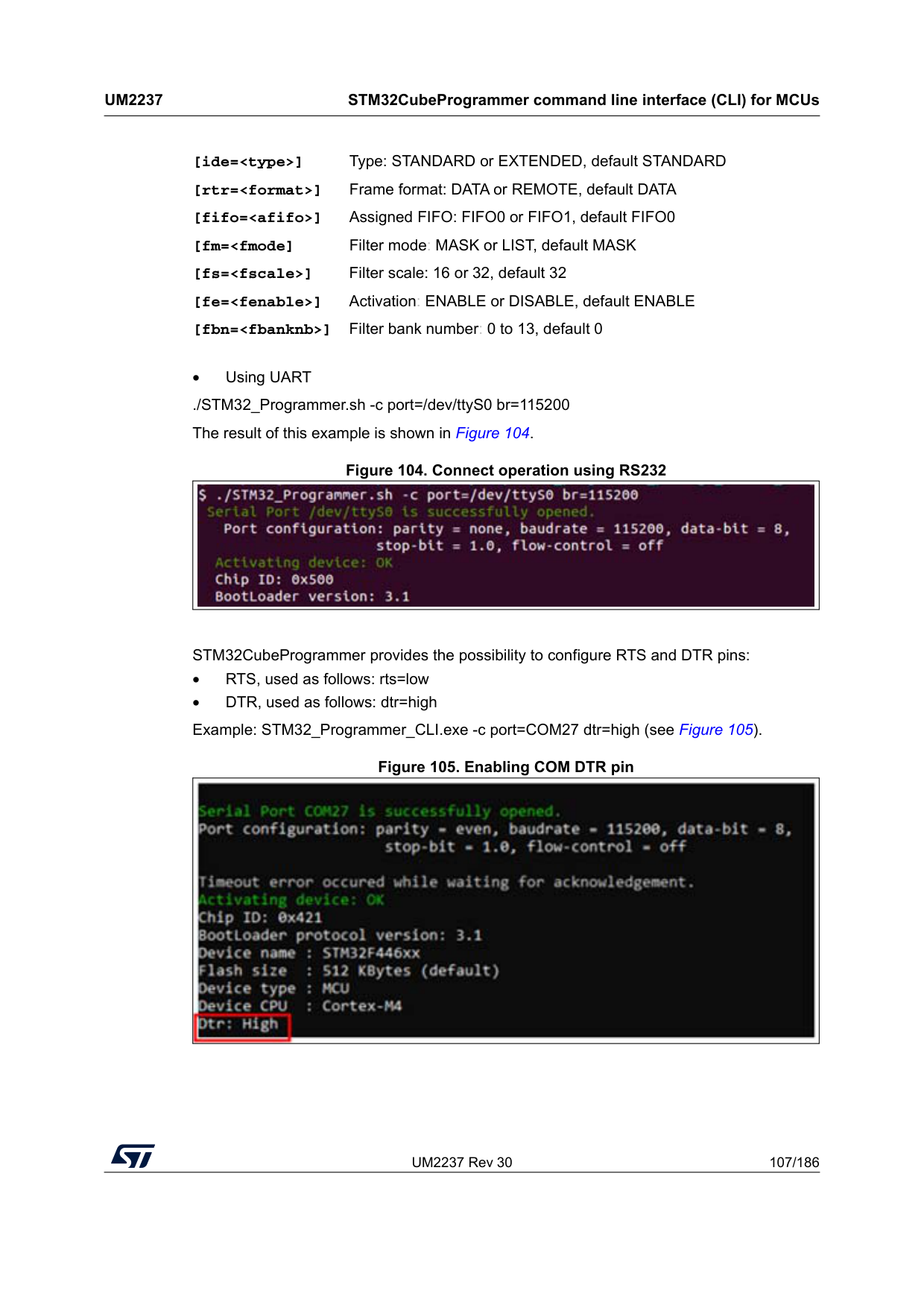
UM2237 Rev 30 107/186
Um2237
STM32CubeProgrammer command line interface (CLI) for MCUs 185• Using UART ./STM32_Programmer.sh -c port=/dev/ttyS0 br=115200 The result of this example is shown in Figure 104. Figure 104. Connect operation using RS232 STM32CubeProgrammer provides the possibility to configure RTS and DTR pins: • RTS, used as follows: rts=low • DTR, used as follows: dtr=high Example: STM32_Programmer_CLI.exe -c port=COM27 dtr=high (see Figure 105). Figure 105. Enabling COM DTR pin [ide=
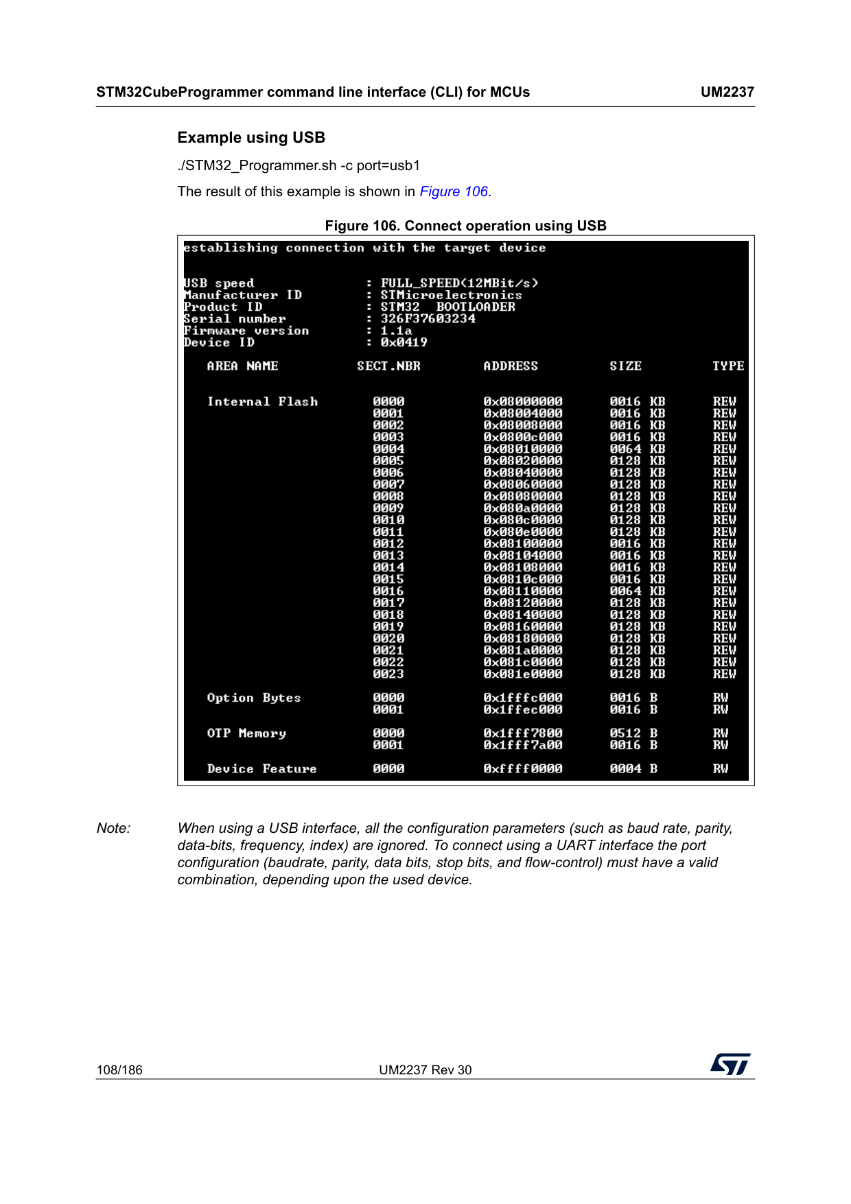
STM32CubeProgrammer command line interface (CLI) for MCUs
Um2237
108/186 UM2237 Rev 30 Example using USB ./STM32_Programmer.sh -c port=usb1 The result of this example is shown in Figure 106. Figure 106. Connect operation using USB Note: When using a USB interface, all the configuration parameters (such as baud rate, parity, data-bits, frequency, index) are ignored. To connect using a UART interface the port configuration (baudrate, parity, data bits, stop bits, and flow-control) must have a valid combination, depending upon the used device.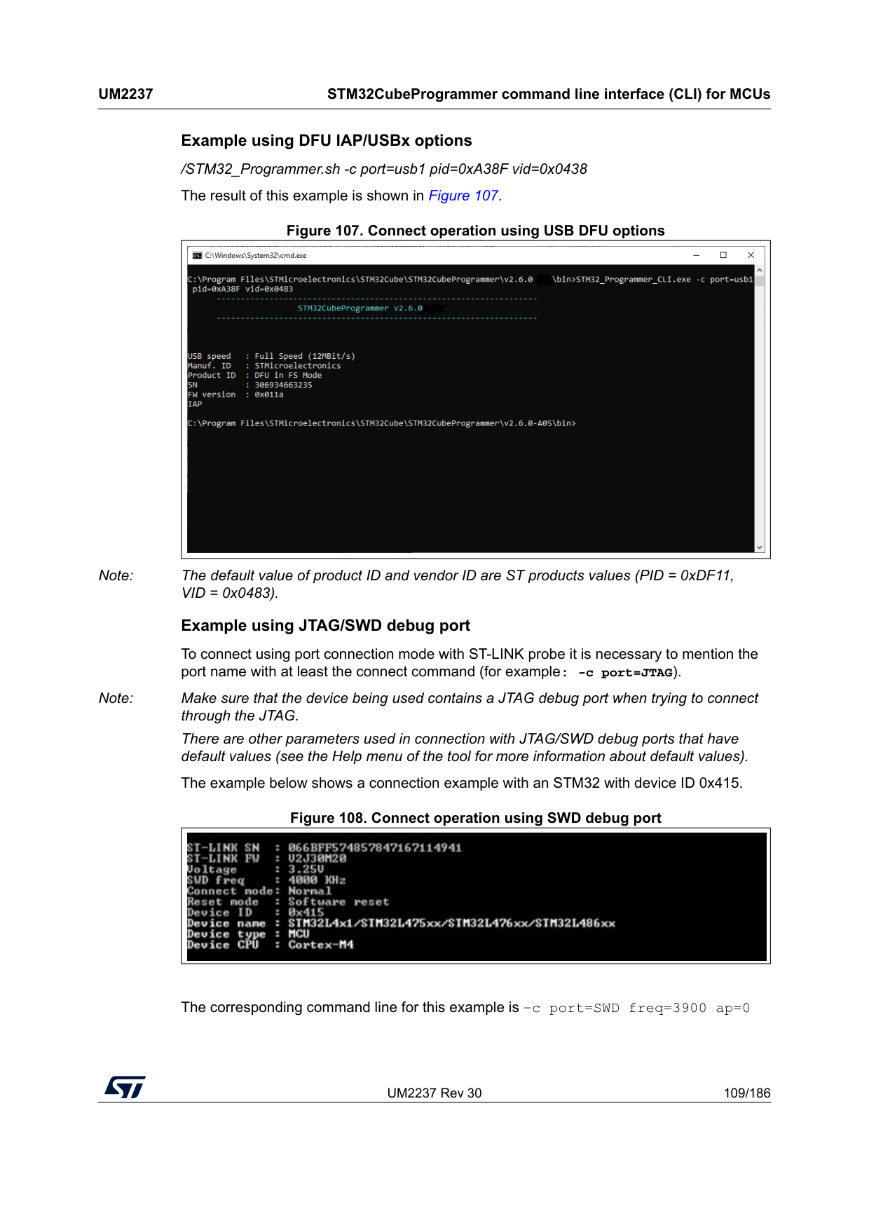
UM2237 Rev 30 109/186
Um2237
STM32CubeProgrammer command line interface (CLI) for MCUs 185 Example using DFU IAP/USBx options /STM32_Programmer.sh -c port=usb1 pid=0xA38F vid=0x0438 The result of this example is shown in Figure 107. Figure 107. Connect operation using USB DFU options Note: The default value of product ID and vendor ID are ST products values (PID = 0xDF11, VID = 0x0483). Example using JTAG/SWD debug port To connect using port connection mode with ST-LINK probe it is necessary to mention the port name with at least the connect command (for example: -c port=JTAG). Note: Make sure that the device being used contains a JTAG debug port when trying to connect through the JTAG. There are other parameters used in connection with JTAG/SWD debug ports that have default values (see the Help menu of the tool for more information about default values). The example below shows a connection example with an STM32 with device ID 0x415. Figure 108. Connect operation using SWD debug port The corresponding command line for this example is –c port=SWD freq=3900 ap=0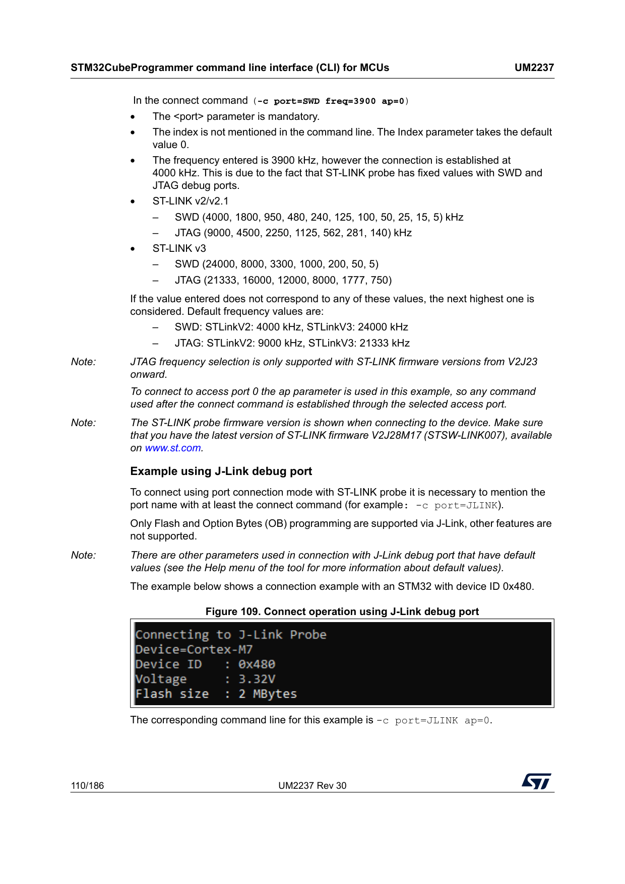
STM32CubeProgrammer command line interface (CLI) for MCUs
Um2237
110/186 UM2237 Rev 30 In the connect command (-c port=SWD freq=3900 ap=0) • TheSwd (24000, 8000, 3300, 1000, 200, 50, 5)
–Jtag (21333, 16000, 12000, 8000, 1777, 750)
If the value entered does not correspond to any of these values, the next highest one is considered. Default frequency values are: – SWD: STLinkV2: 4000 kHz, STLinkV3: 24000 kHz – JTAG: STLinkV2: 9000 kHz, STLinkV3: 21333 kHz Note: JTAG frequency selection is only supported with ST-LINK firmware versions from V2J23 onward. To connect to access port 0 the ap parameter is used in this example, so any command used after the connect command is established through the selected access port. Note: The ST-LINK probe firmware version is shown when connecting to the device. Make sure that you have the latest version of ST-LINK firmware V2J28M17 (STSW-LINK007), available on www.st.com. Example using J-Link debug port To connect using port connection mode with ST-LINK probe it is necessary to mention the port name with at least the connect command (for example: -c port=JLINK). Only Flash and Option Bytes (OB) programming are supported via J-Link, other features are not supported. Note: There are other parameters used in connection with J-Link debug port that have default values (see the Help menu of the tool for more information about default values). The example below shows a connection example with an STM32 with device ID 0x480. Figure 109. Connect operation using J-Link debug port The corresponding command line for this example is -c port=JLINK ap=0.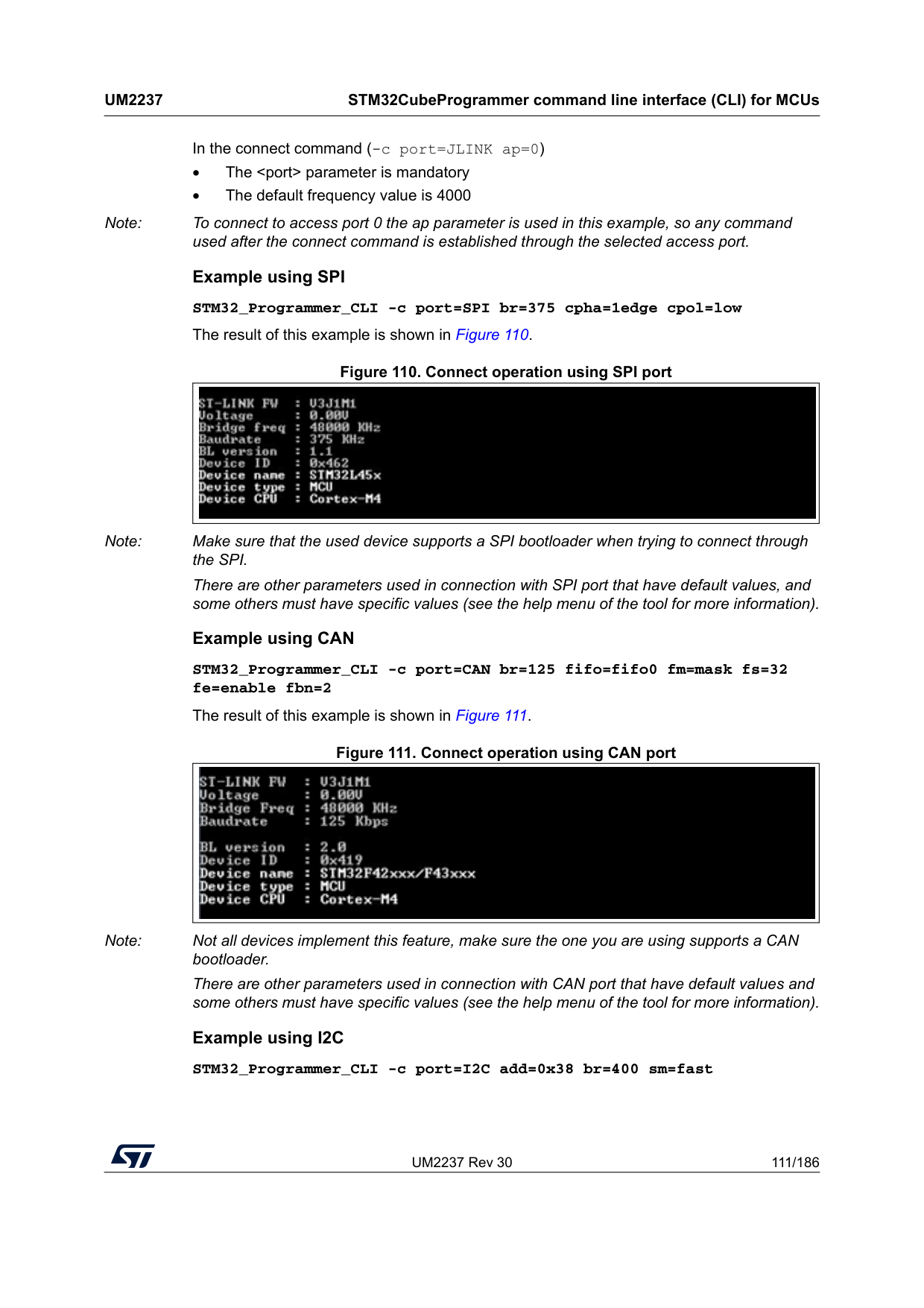
UM2237 Rev 30 111/186
Um2237
STM32CubeProgrammer command line interface (CLI) for MCUs 185 In the connect command (-c port=JLINK ap=0) • The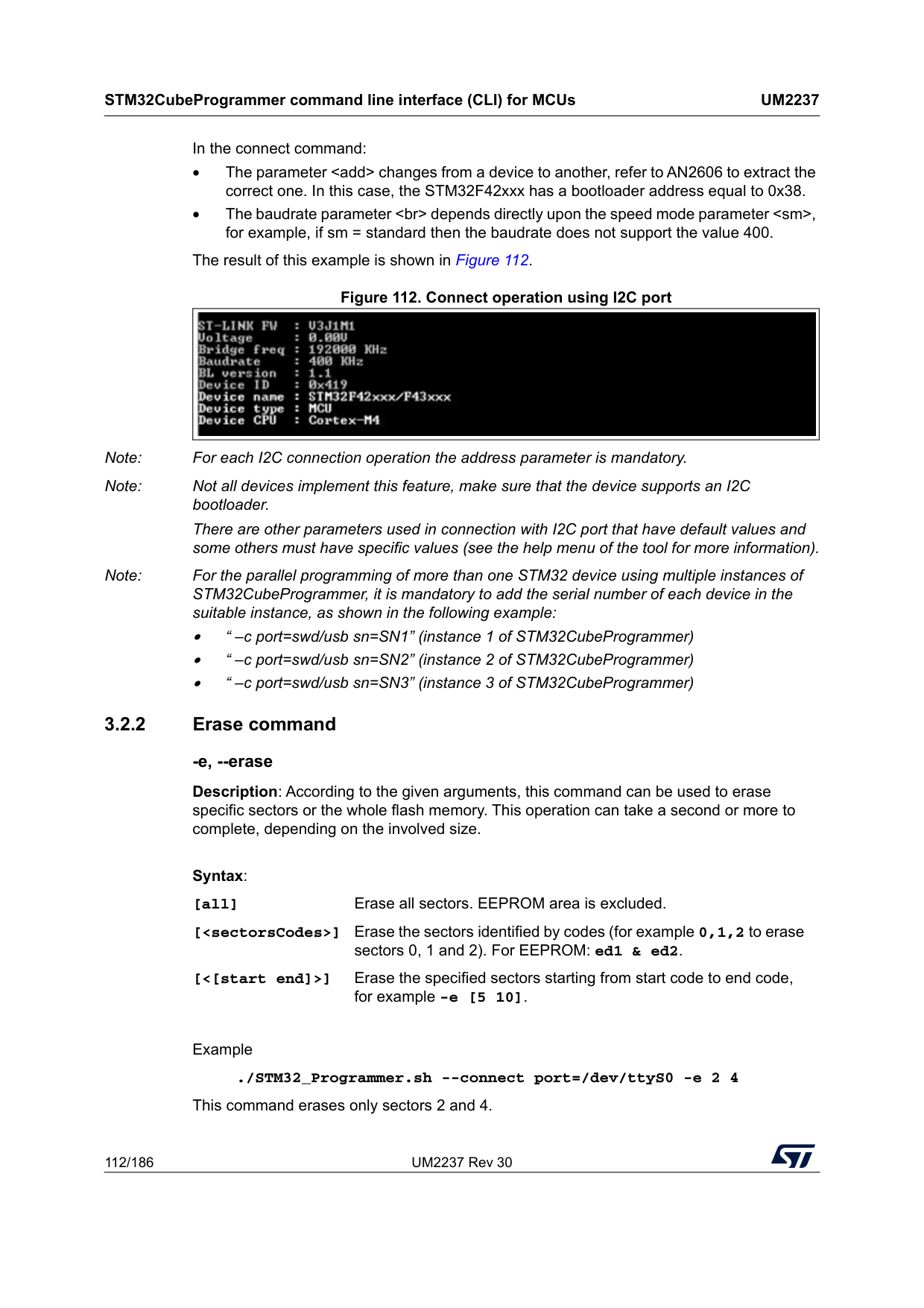
STM32CubeProgrammer command line interface (CLI) for MCUs
Um2237
112/186 UM2237 Rev 30 In the connect command: • The parameterdepends directly upon the speed mode parameter
Example ./STM32_Programmer.sh --connect port=/dev/ttyS0 -e 2 4 This command erases only sectors 2 and 4. Syntax: [all] Erase all sectors. EEPROM area is excluded. [
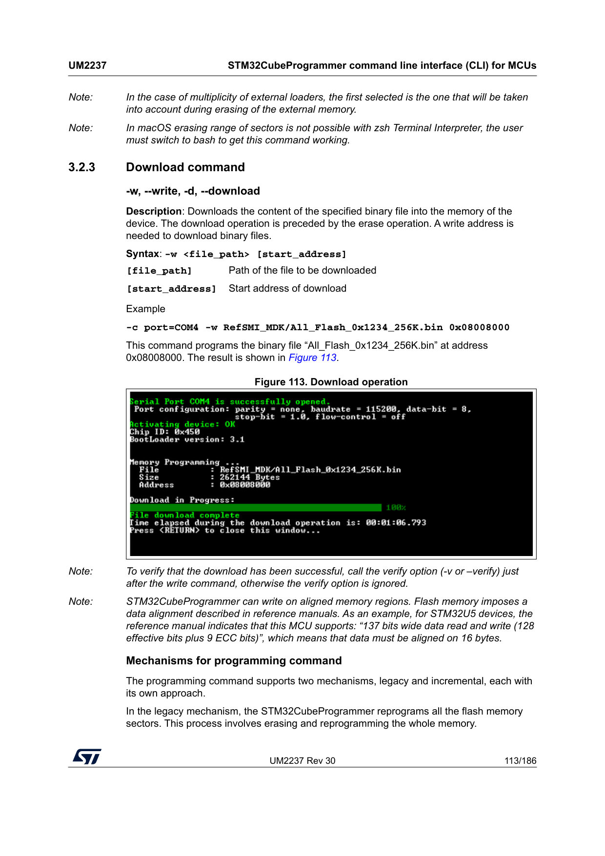
UM2237 Rev 30 113/186
Um2237
STM32CubeProgrammer command line interface (CLI) for MCUs 185 Note: In the case of multiplicity of external loaders, the first selected is the one that will be taken into account during erasing of the external memory. Note: In macOS erasing range of sectors is not possible with zsh Terminal Interpreter, the user must switch to bash to get this command working. 3.2.3 Download command -w, --write, -d, --download Description: Downloads the content of the specified binary file into the memory of the device. The download operation is preceded by the erase operation. A write address is needed to download binary files. Syntax: -w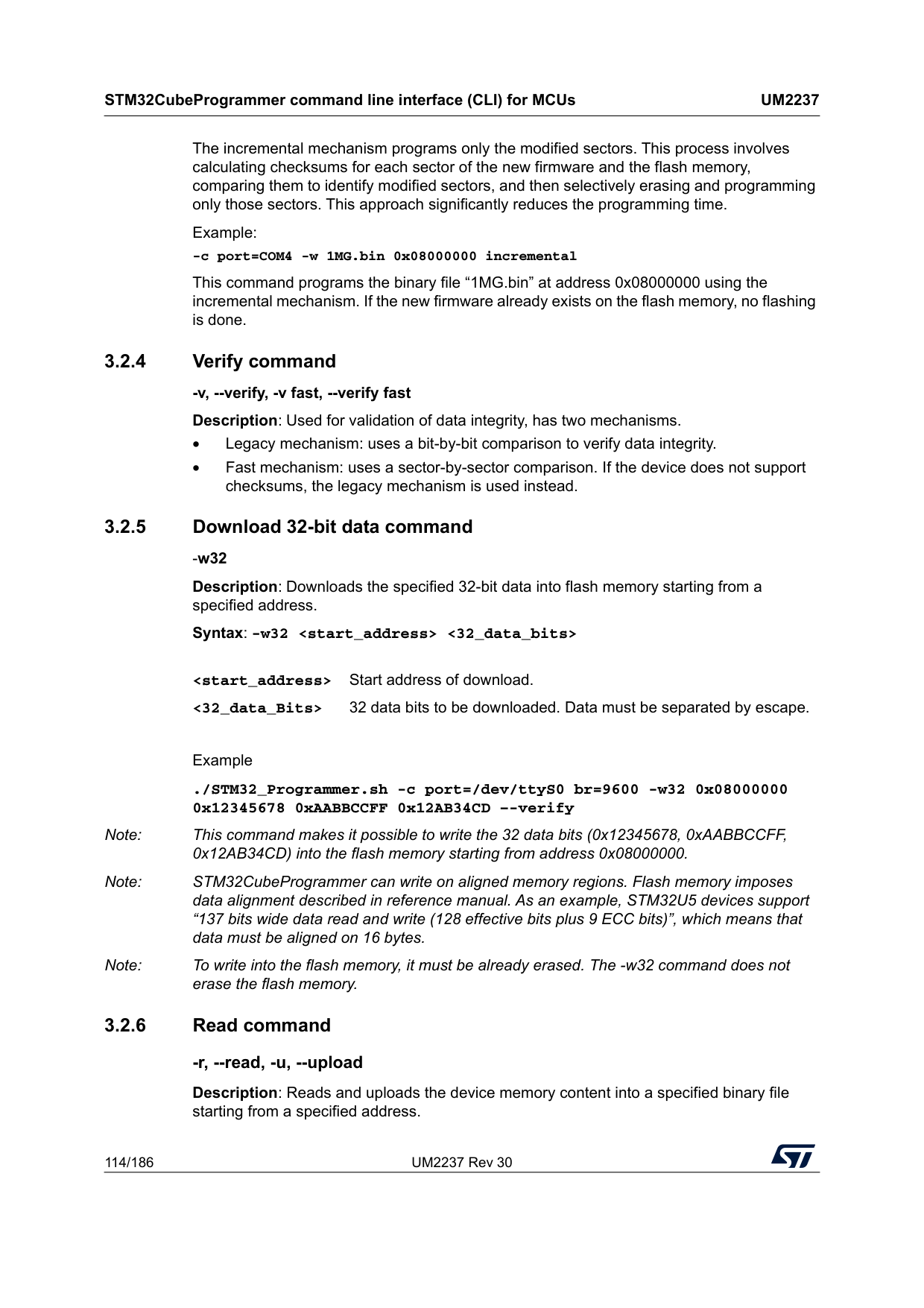
STM32CubeProgrammer command line interface (CLI) for MCUs
Um2237
114/186 UM2237 Rev 30 The incremental mechanism programs only the modified sectors. This process involves calculating checksums for each sector of the new firmware and the flash memory, comparing them to identify modified sectors, and then selectively erasing and programming only those sectors. This approach significantly reduces the programming time. Example: -c port=COM4 -w 1MG.bin 0x08000000 incremental This command programs the binary file “1MG.bin” at address 0x08000000 using the incremental mechanism. If the new firmware already exists on the flash memory, no flashing is done. 3.2.4 Verify command -v, --verify, -v fast, --verify fast Description: Used for validation of data integrity, has two mechanisms. • Legacy mechanism: uses a bit-by-bit comparison to verify data integrity. • Fast mechanism: uses a sector-by-sector comparison. If the device does not support checksums, the legacy mechanism is used instead. 3.2.5 Download 32-bit data command -w32 Description: Downloads the specified 32-bit data into flash memory starting from a specified address. Syntax: -w32Example ./STM32_Programmer.sh -c port=/dev/ttyS0 br=9600 -w32 0x08000000 0x12345678 0xAABBCCFF 0x12AB34CD –-verify Note: This command makes it possible to write the 32 data bits (0x12345678, 0xAABBCCFF, 0x12AB34CD) into the flash memory starting from address 0x08000000. Note: STM32CubeProgrammer can write on aligned memory regions. Flash memory imposes data alignment described in reference manual. As an example, STM32U5 devices support “137 bits wide data read and write (128 effective bits plus 9 ECC bits)”, which means that data must be aligned on 16 bytes. Note: To write into the flash memory, it must be already erased. The -w32 command does not erase the flash memory. 3.2.6 Read command -r, --read, -u, --upload Description: Reads and uploads the device memory content into a specified binary file starting from a specified address.
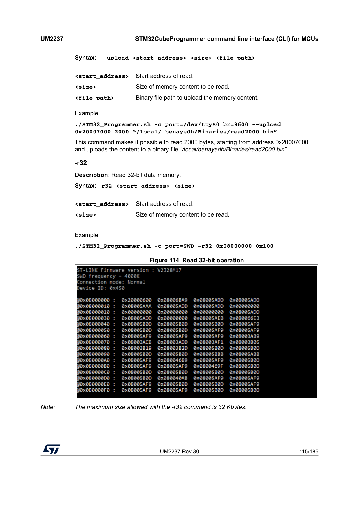
UM2237 Rev 30 115/186
Um2237
STM32CubeProgrammer command line interface (CLI) for MCUs 185 Syntax: --uploadExample ./STM32_Programmer.sh -c port=/dev/ttyS0 br=9600 --upload 0x20007000 2000 “/local/ benayedh/Binaries/read2000.bin” This command makes it possible to read 2000 bytes, starting from address 0x20007000, and uploads the content to a binary file “/local/benayedh/Binaries/read2000.bin” -r32 Description: Read 32-bit data memory. Syntax: -r32
Example ./STM32_Programmer.sh -c port=SWD –r32 0x08000000 0x100 Figure 114. Read 32-bit operation Note: The maximum size allowed with the -r32 command is 32 Kbytes.
STM32CubeProgrammer command line interface (CLI) for MCUs
Um2237
116/186 UM2237 Rev 30 3.2.7 Start command -g, --go, -s, --start Description: This command enables execution of the device memory starting from the specified address. Syntax: --start [start_address] [start_address] Start address of application to be executed. Example ./STM32_Programmer.sh --connect port=/dev/ttyS0 br=9600 --start 0x08000000 This command runs the code specified at 0x08000000. 3.2.8 Debug commands The following commands are available only with the JTAG/SWD debug port. -rst Description: Executes a software system reset; Syntax: -rst -hardRst Description: Generates a hardware reset through the RESET pin in the debug connector. The RESET pin of the JTAG connector (pin 15) must be connected to the device reset pin. Syntax: -hardRst -halt Description: Halts the core. Syntax: -halt -step Description: Executes one instruction. Syntax: -step -score Description: Displays the Cortex-M core status. The core status can be one of the following: ”Running”, ”Halted”, ”Locked up”, ”Reset”, ”Locked up” or ”Kept under reset” Syntax: -score -coreReg Description: Read/write Cortex-M core registers. The core is halted before a read/write operation.
UM2237 Rev 30 117/186
Um2237
STM32CubeProgrammer command line interface (CLI) for MCUs 185 Syntax: -coreReg [R0/../R15/Pc/Lr/Psp/Msp/Xpsr/Apsr/Ipsr/Epsr/Primask/Basepri/
Faultmask/Control
[core_reg=3.2.9 List command -l, -list Description: This command lists all available UART, DFU and STLink interfaces. Syntax: -l, --list Example (result shown in Figure 115): ./STM32_Programmer.sh --list 3.2.10 SWD Multidrop SWD (Serial Wire Debug) Multidrop is an enhancement to the standard SWD protocol, commonly used to debug microcontrollers based on Cortex-M cores. This feature allows a single SWD interface (from a debugger or programmer) to communicate with multiple target devices connected on the same SWD bus. Only flash and option bytes (OB) programming are supported. -getTargetSelList Description: Lists all the devices currently connected via ST-LINK on the same SWD bus supporting the SWD multidrop. Syntax: -getTargetSelList Example (result shown in Figure 116) Note: If no board is detected, the command returns “No STM32 Target Found!” If the connected boards use an outdated ST-LINK firmware, the command returns “Too Old Firmware, please upgrade your STLINK!” Once the ST-LINK firmware is updated, all connected devices supporting the SWD Multidrop are correctly listed. Limitation: only devices with different TargetSel can be connected simultaneously to the same ST-LINK. New option in Connect command: TargetSel Description: Specifies the target device by its TargetSel value. Syntax: TargetSel=
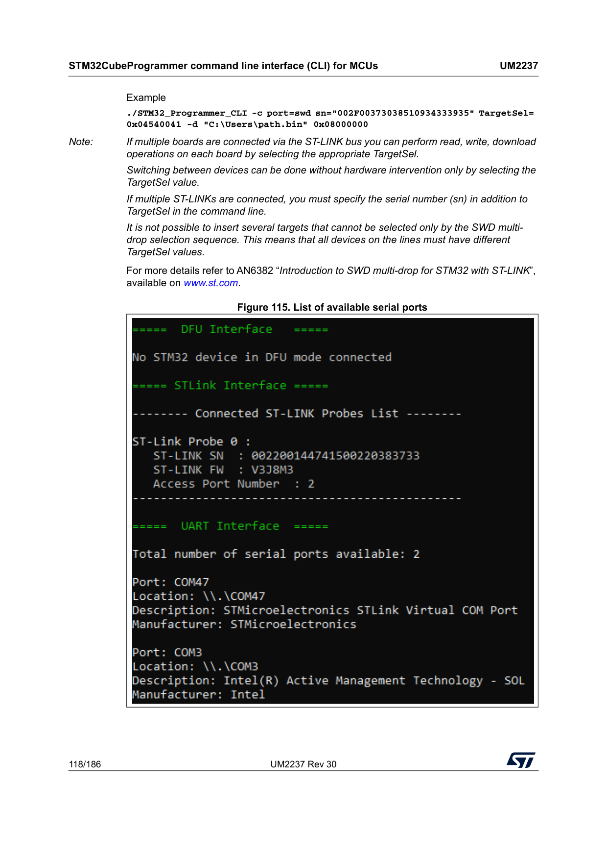
STM32CubeProgrammer command line interface (CLI) for MCUs
Um2237
118/186 UM2237 Rev 30 Example ./STM32_Programmer_CLI -c port=swd sn="002F00373038510934333935" TargetSel= 0x04540041 -d "C:\Users\path.bin" 0x08000000 Note: If multiple boards are connected via the ST-LINK bus you can perform read, write, download operations on each board by selecting the appropriate TargetSel. Switching between devices can be done without hardware intervention only by selecting the TargetSel value. If multiple ST-LINKs are connected, you must specify the serial number (sn) in addition to TargetSel in the command line. It is not possible to insert several targets that cannot be selected only by the SWD multi- drop selection sequence. This means that all devices on the lines must have different TargetSel values. For more details refer to AN6382 “Introduction to SWD multi-drop for STM32 with ST-LINK”, available on www.st.com. Figure 115. List of available serial ports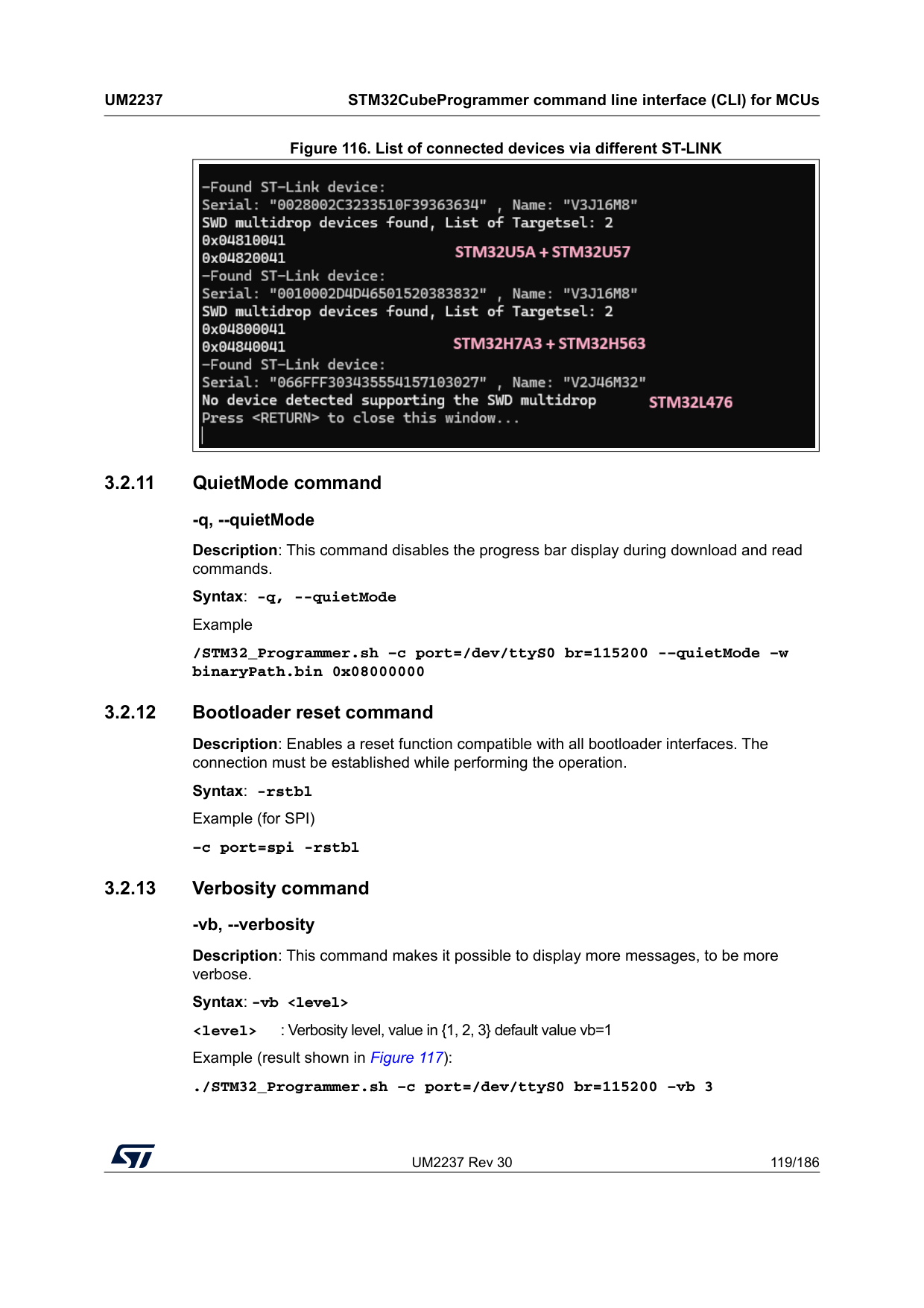
UM2237 Rev 30 119/186
Um2237
STM32CubeProgrammer command line interface (CLI) for MCUs 185 Figure 116. List of connected devices via different ST-LINK 3.2.11 QuietMode command -q, --quietMode Description: This command disables the progress bar display during download and read commands. Syntax: -q, --quietMode Example /STM32_Programmer.sh –c port=/dev/ttyS0 br=115200 -–quietMode –w binaryPath.bin 0x08000000 3.2.12 Bootloader reset command Description: Enables a reset function compatible with all bootloader interfaces. The connection must be established while performing the operation. Syntax: -rstbl Example (for SPI) –c port=spi -rstbl 3.2.13 Verbosity command -vb, --verbosity Description: This command makes it possible to display more messages, to be more verbose. Syntax: -vb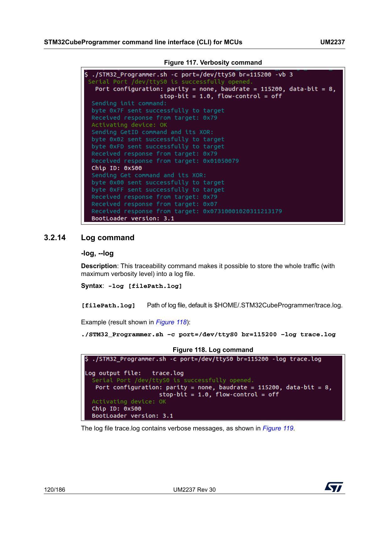
STM32CubeProgrammer command line interface (CLI) for MCUs
Um2237
120/186 UM2237 Rev 30 Figure 117. Verbosity command 3.2.14 Log command -log, --log Description: This traceability command makes it possible to store the whole traffic (with maximum verbosity level) into a log file. Syntax: -log [filePath.log]Example (result shown in Figure 118): ./STM32_Programmer.sh –c port=/dev/ttyS0 br=115200 –log trace.log Figure 118. Log command The log file trace.log contains verbose messages, as shown in Figure 119. [filePath.log] Path of log file, default is $HOME/.STM32CubeProgrammer/trace.log.
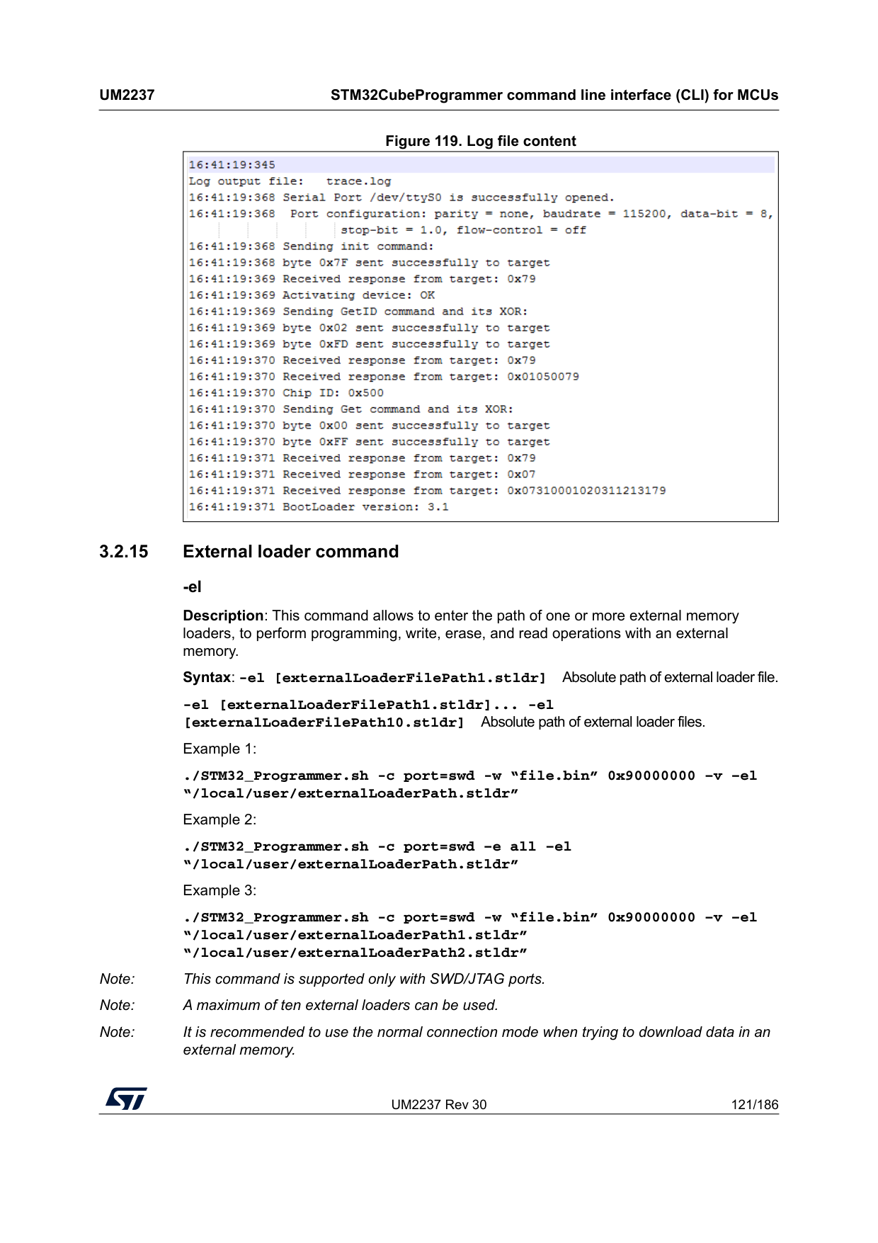
UM2237 Rev 30 121/186
Um2237
STM32CubeProgrammer command line interface (CLI) for MCUs 185 Figure 119. Log file content 3.2.15 External loader command -el Description: This command allows to enter the path of one or more external memory loaders, to perform programming, write, erase, and read operations with an external memory. Syntax: -el [externalLoaderFilePath1.stldr] Absolute path of external loader file. -el [externalLoaderFilePath1.stldr]... -el [externalLoaderFilePath10.stldr] Absolute path of external loader files. Example 1: ./STM32_Programmer.sh -c port=swd -w “file.bin” 0x90000000 –v –el “/local/user/externalLoaderPath.stldr” Example 2: ./STM32_Programmer.sh -c port=swd –e all –el “/local/user/externalLoaderPath.stldr” Example 3: ./STM32_Programmer.sh -c port=swd -w “file.bin” 0x90000000 –v –el “/local/user/externalLoaderPath1.stldr” “/local/user/externalLoaderPath2.stldr” Note: This command is supported only with SWD/JTAG ports. Note: A maximum of ten external loaders can be used. Note: It is recommended to use the normal connection mode when trying to download data in an external memory.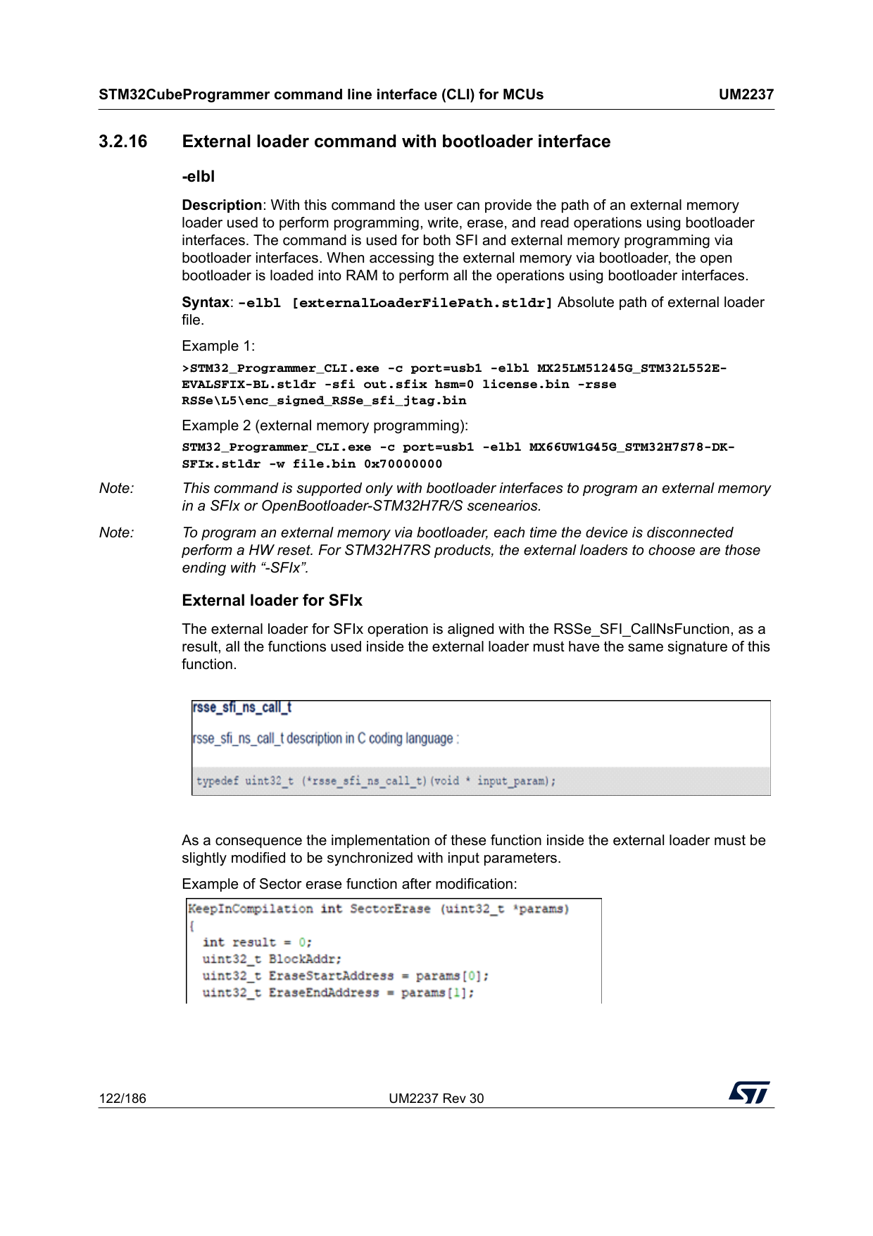
STM32CubeProgrammer command line interface (CLI) for MCUs
Um2237
122/186 UM2237 Rev 30 3.2.16 External loader command with bootloader interface -elbl Description: With this command the user can provide the path of an external memory loader used to perform programming, write, erase, and read operations using bootloader interfaces. The command is used for both SFI and external memory programming via bootloader interfaces. When accessing the external memory via bootloader, the open bootloader is loaded into RAM to perform all the operations using bootloader interfaces. Syntax: -elbl [externalLoaderFilePath.stldr] Absolute path of external loader file. Example 1: >STM32_Programmer_CLI.exe -c port=usb1 -elbl MX25LM51245G_STM32L552E- EVALSFIX-BL.stldr -sfi out.sfix hsm=0 license.bin -rsse RSSe\L5\enc_signed_RSSe_sfi_jtag.bin Example 2 (external memory programming): STM32_Programmer_CLI.exe -c port=usb1 -elbl MX66UW1G45G_STM32H7S78-DK- SFIx.stldr -w file.bin 0x70000000 Note: This command is supported only with bootloader interfaces to program an external memory in a SFIx or OpenBootloader-STM32H7R/S scenearios. Note: To program an external memory via bootloader, each time the device is disconnected perform a HW reset. For STM32H7RS products, the external loaders to choose are those ending with “-SFIx”. External loader for SFIx The external loader for SFIx operation is aligned with the RSSe_SFI_CallNsFunction, as a result, all the functions used inside the external loader must have the same signature of this function.As a consequence the implementation of these function inside the external loader must be slightly modified to be synchronized with input parameters. Example of Sector erase function after modification:
UM2237 Rev 30 123/186
Um2237
STM32CubeProgrammer command line interface (CLI) for MCUs 185 3.2.17 Read unprotect command -rdu, --readunprotect Description: This command removes the memory read protection by changing the RDP level from level 1 to level 0. Syntax: --readunprotect Example ./STM32_Programmer.sh –c port=swd –rdu 3.2.18 TZ regression command -tzenreg, --tzenregression Description: This command removes TrustZone protection by disabling TZEN from 1 to 0. Syntax: --tzenregression Example ./STM32_Programmer.sh –c port=usb1 –tzenreg Note: This command is only supported for bootloader interface and MCUs with trusted zone. 3.2.19 Option bytes command -ob, --optionbytes Description: This command allows the user to manipulate the device option bytes by displaying or modifying them. Syntax: -ob [displ] / -ob [OptByte=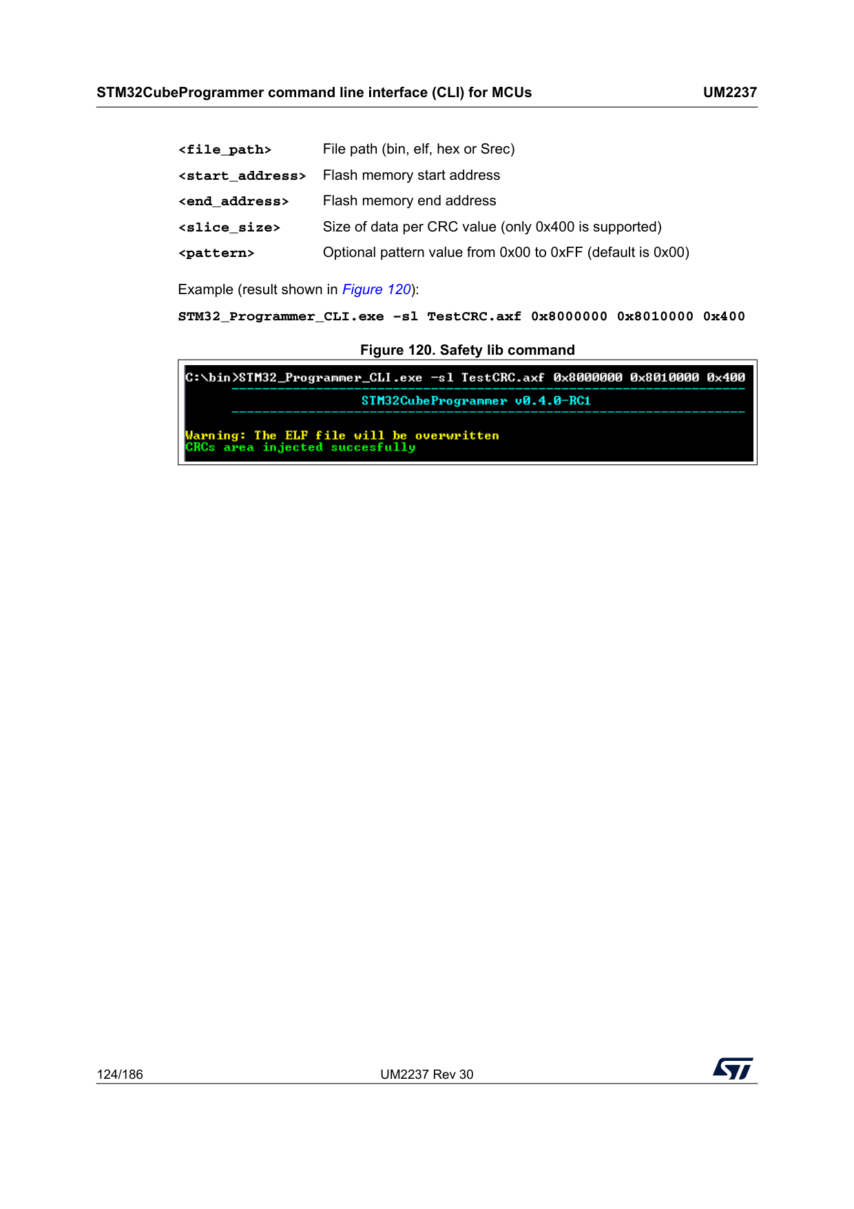
STM32CubeProgrammer command line interface (CLI) for MCUs
Um2237
124/186 UM2237 Rev 30Example (result shown in Figure 120): STM32_Programmer_CLI.exe –sl TestCRC.axf 0x8000000 0x8010000 0x400 Figure 120. Safety lib command
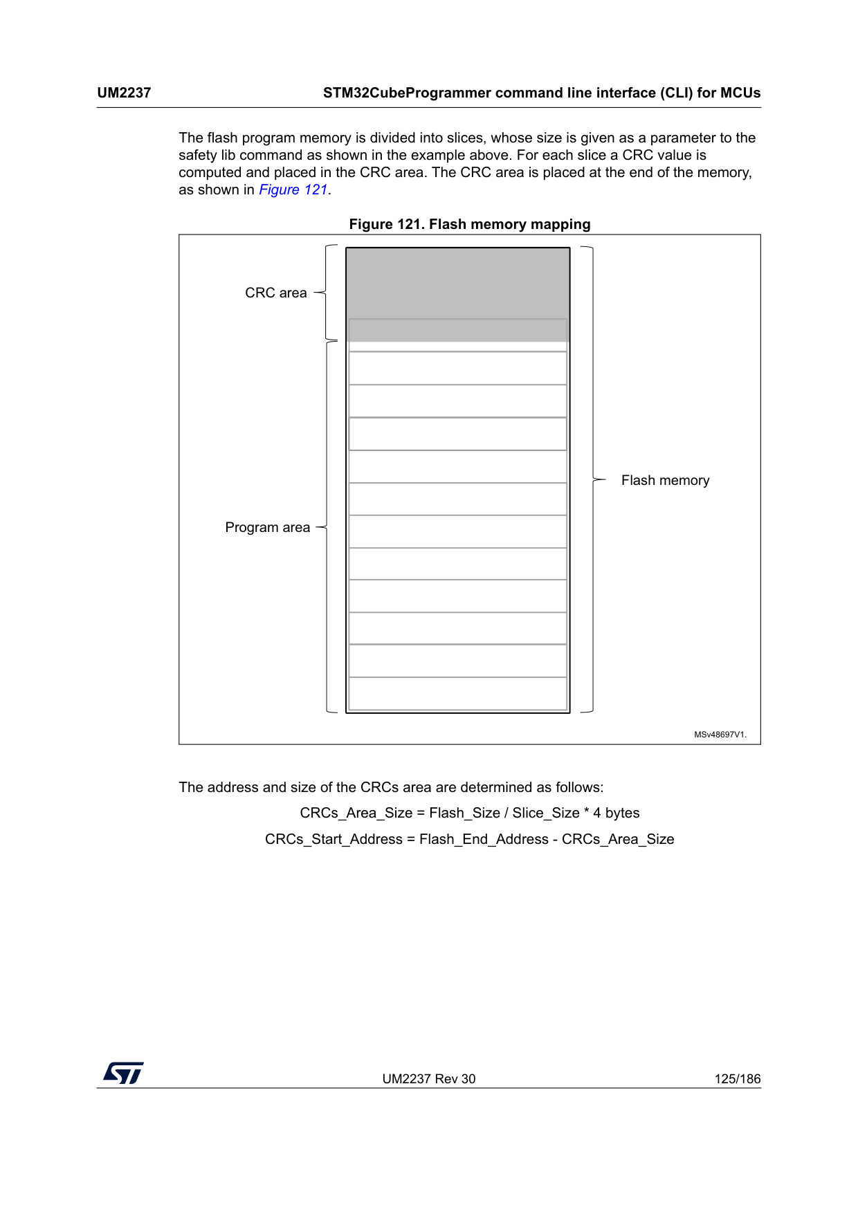
UM2237 Rev 30 125/186
Um2237
STM32CubeProgrammer command line interface (CLI) for MCUs 185 The flash program memory is divided into slices, whose size is given as a parameter to the safety lib command as shown in the example above. For each slice a CRC value is computed and placed in the CRC area. The CRC area is placed at the end of the memory, as shown in Figure 121. Figure 121. Flash memory mapping The address and size of the CRCs area are determined as follows: CRCs_Area_Size = Flash_Size / Slice_Size * 4 bytes CRCs_Start_Address = Flash_End_Address - CRCs_Area_Size MSv48697V1. Flash memory CRC area Program area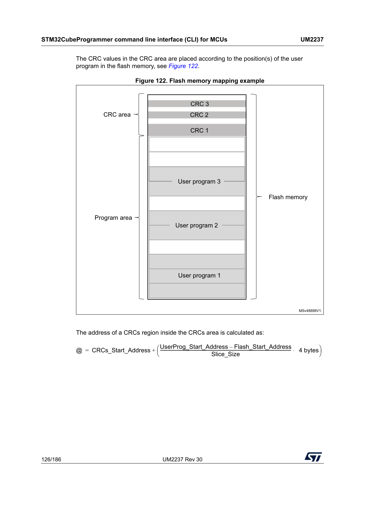
STM32CubeProgrammer command line interface (CLI) for MCUs
Um2237
126/186 UM2237 Rev 30 The CRC values in the CRC area are placed according to the position(s) of the user program in the flash memory, see Figure 122. Figure 122. Flash memory mapping example The address of a CRCs region inside the CRCs area is calculated as: MSv48698V1. Flash memory CRC area Program areaCrc 1
User program 1Crc 2
Crc 3
User program 2 User program 3 @ CRCs_Start_Address UserProg_Start_Address Flash_Start_Address – Slice_Size -------------------------------------------------------------------------------------------------------------------------------- 4 bytes ⋅ ⎝ ⎠ ⎛ ⎞ + =
UM2237 Rev 30 127/186
Um2237
STM32CubeProgrammer command line interface (CLI) for MCUs 185 The tool checks the syntax and the processing of the command, and marks a failure if there is a parameters mismatch or a problem in the CRC calculation by displaying various error message: • “Invalid file path or wrong file extension”
STM32CubeProgrammer command line interface (CLI) for MCUs
Um2237
128/186 UM2237 Rev 30 3.2.21 Secure programming SFI specific commands Secure firmware install (SFI) is a feature supporting secure firmware flashing, available on some STM32 devices. The firmware provider has the possibility to protect its internal firmware against any illegal access, and to control the number of devices that can be programmed. The protected firmware installation can be performed using different communication channels, such as JTAG/SWD or bootloader interfaces (UART, SPI and USB). For more details refer to AN5054. -sfi, --sfi Description: Programs an sfi file Syntax: -sfi [-rsse, --rsse Description: This command allows the user to select the root secure services extension library (RSSe). Mandatory for devices using RSSe to make secure firmware install (SFI). The RSSe binary file can be found in STM32CubeProgrammer bin/RSSe folder. Syntax: -rsse
UM2237 Rev 30 129/186
Um2237
STM32CubeProgrammer command line interface (CLI) for MCUs 185 3.2.22 Secure programming SFIx specific commands Secure firmware install (SFIx) is a feature supporting secure external firmware flashing, available on some STM32 devices with OTFDEC capability. The firmware provider has the possibility to protect its external firmware/data against any illegal access, and to control the number of devices that can be programmed. The SFIx secure programming can be carried out only with JTAG/SWD interface. For more details refer to AN5054. -sfi, --sfi Description: Programs an sfix file Syntax: -sfi [-rsse, --rsse Description: This command allows the user to select the root secure services extension library (RSSe). Mandatory for devices using RSSe to make secure firmware install (SFI). The RSSe binary file can be found in STM32CubeProgrammer bin/RSSe folder. Syntax: -rsse
STM32CubeProgrammer command line interface (CLI) for MCUs
Um2237
130/186 UM2237 Rev 30 -mcsv, --mcsv Description: This command allows the user to select the modules file including the list of modules to be installed with SFI. This option is mandatory when the SFI image integrates at least one module (area of type m). Syntax: -mcsv-hsmgetfwid Description: Reads the Firmware/Module identifier [slot=
UM2237 Rev 30 131/186
Um2237
STM32CubeProgrammer command line interface (CLI) for MCUs 185 Syntax: -hsmgetfwid [slot=-hsmgetstatus Description: Reads the current card life-cycle state Syntax: -hsmgetstatus [slot=
-hsmgetlicense Description: Gets a license for the current chip if counter is not null Syntax: -hsmgetlicense
-hsmgetlicensefromcertifbin, -hsmglfcb Description: Gets a license for the current certificate binary file if counter is not null. Syntax: -hsmglfcb
[slot=
STM32CubeProgrammer command line interface (CLI) for MCUs
Um2237
132/186 UM2237 Rev 30 3.2.24 STM32WB specific commands -antirollback Description: Perform the antirollback operation Syntax: -antirollback -startfus Description: Start the FUS Syntax: -startfus -getuid64 Description: Read the device unique identifier (UID) Syntax: -getuid64 -fusgetstate Description: Read the FUS state Syntax: -fusgetstate -fusopgetversion Description: Read the FUS o//perator version Syntax: -fusgetversion Note: FUS operator version is not available via bootloader interfaces. -fwdelete Description: Delete the BLE stack firmware Syntax: -fwdelete -fwupgrade Description: Upgrade of BLE stack firmware or FUS firmware. Syntax: -fwupgrade
UM2237 Rev 30 133/186
Um2237
STM32CubeProgrammer command line interface (CLI) for MCUs 185 -startwirelessstack Description: Start the wireless stack Syntax: -startwirelessstack -authkeyupdate Description: Authentication key update Syntax: -authkeyupdate-authkeylock Description: Authentication key lock Once locked, it is no longer possible to change it using -authkeyupdate command Syntax: -authkeylock -wusrkey For more information about the customer key storage, refer to already cited AN5185. Syntax: -wusrkey
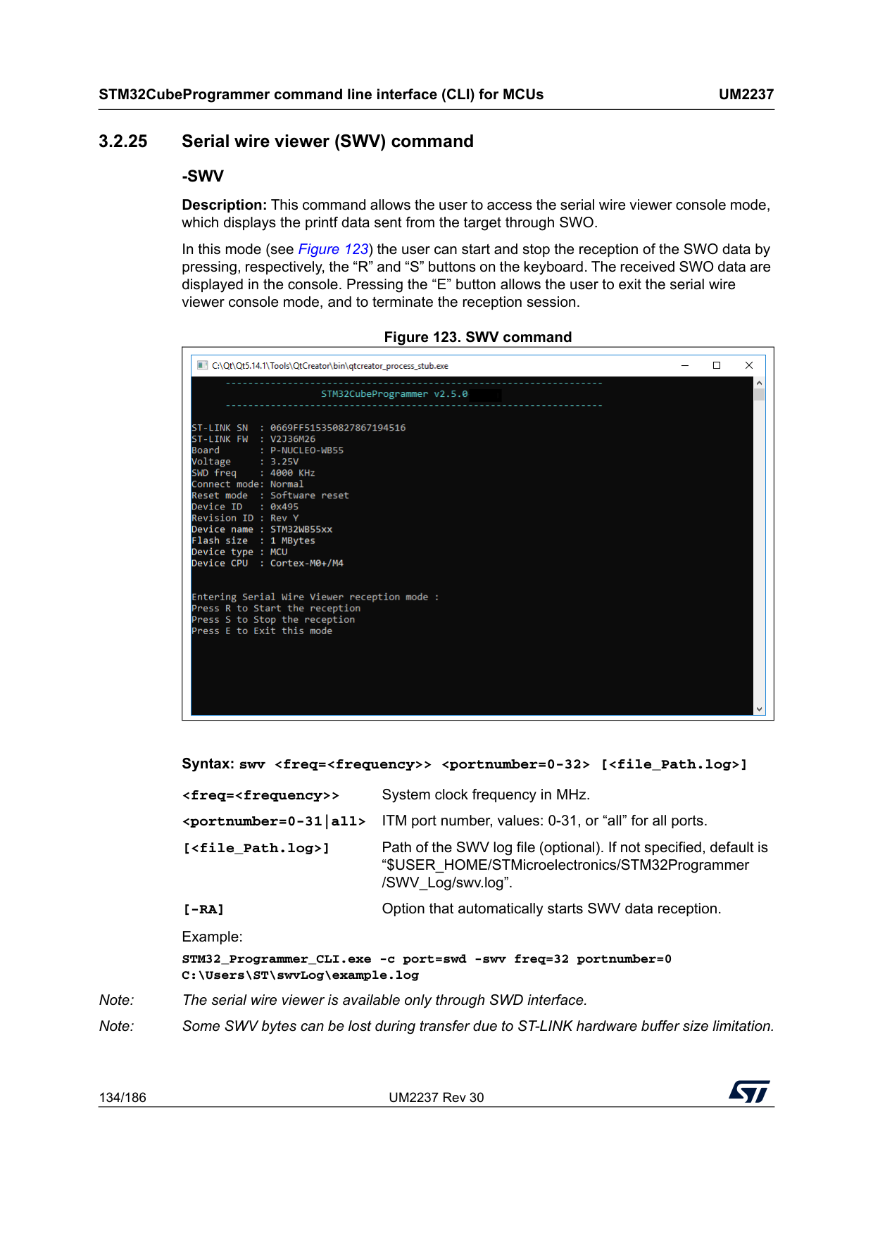
STM32CubeProgrammer command line interface (CLI) for MCUs
Um2237
134/186 UM2237 Rev 30 3.2.25 Serial wire viewer (SWV) command-Swv
Description: This command allows the user to access the serial wire viewer console mode, which displays the printf data sent from the target through SWO. In this mode (see Figure 123) the user can start and stop the reception of the SWO data by pressing, respectively, the “R” and “S” buttons on the keyboard. The received SWO data are displayed in the console. Pressing the “E” button allows the user to exit the serial wire viewer console mode, and to terminate the reception session. Figure 123. SWV command Syntax: swv[-Ra]
Option that automatically starts SWV data reception.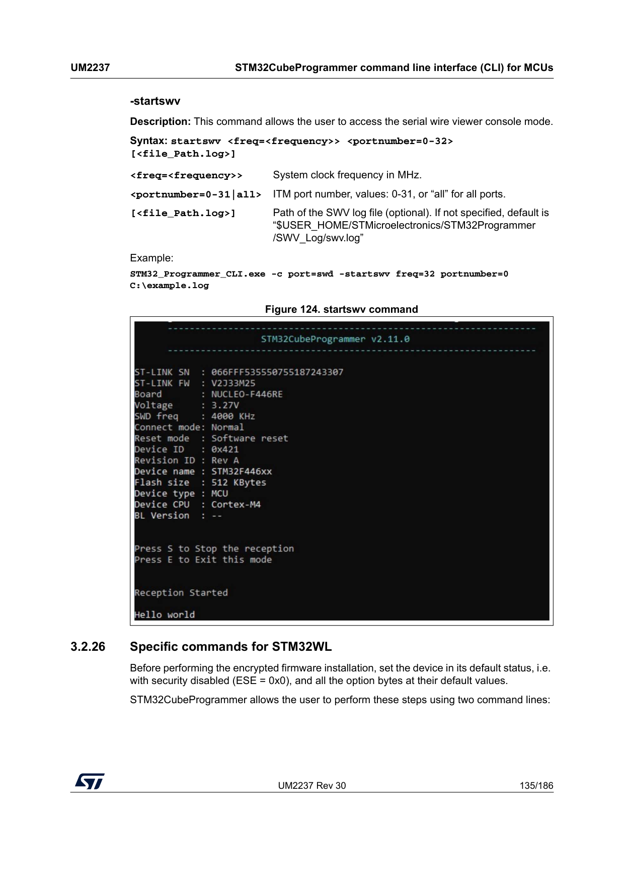
UM2237 Rev 30 135/186
Um2237
STM32CubeProgrammer command line interface (CLI) for MCUs 185 -startswv Description: This command allows the user to access the serial wire viewer console mode. Syntax: startswv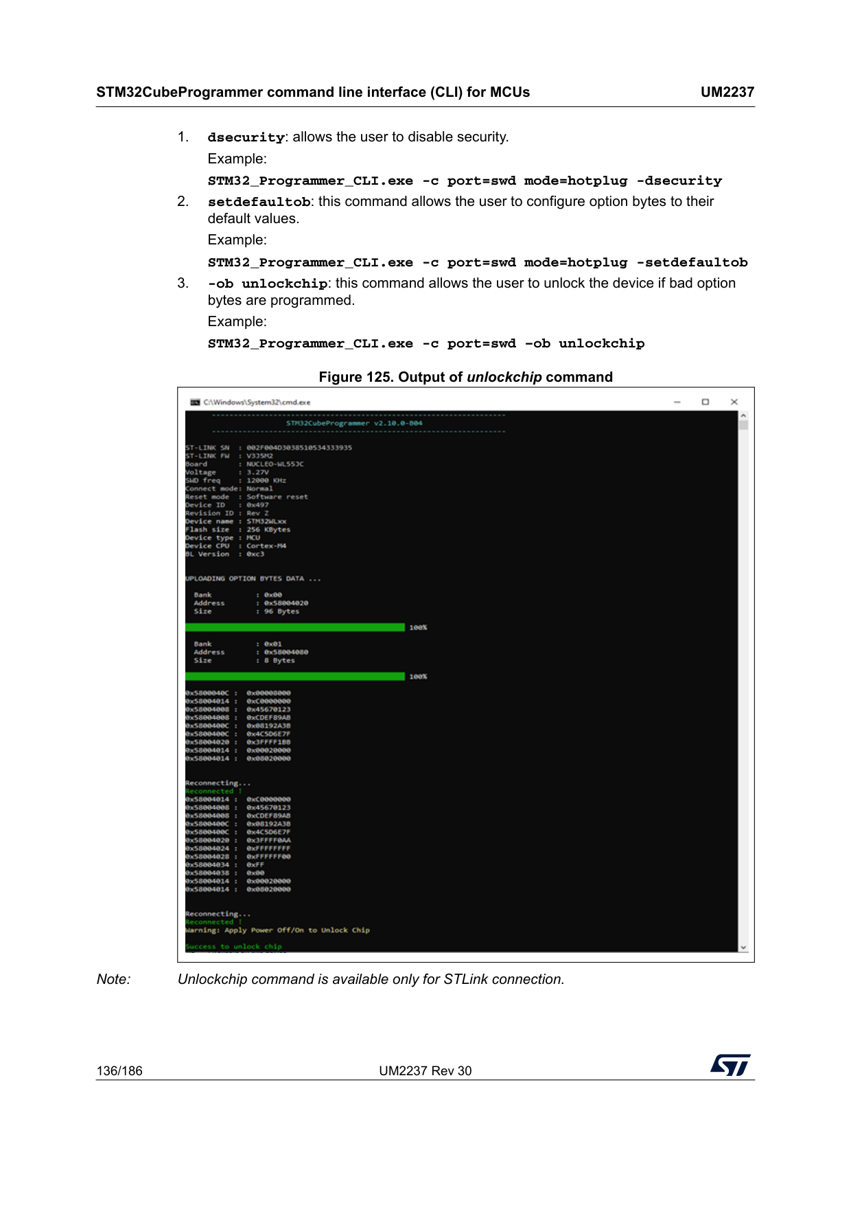
STM32CubeProgrammer command line interface (CLI) for MCUs
Um2237
136/186 UM2237 Rev 30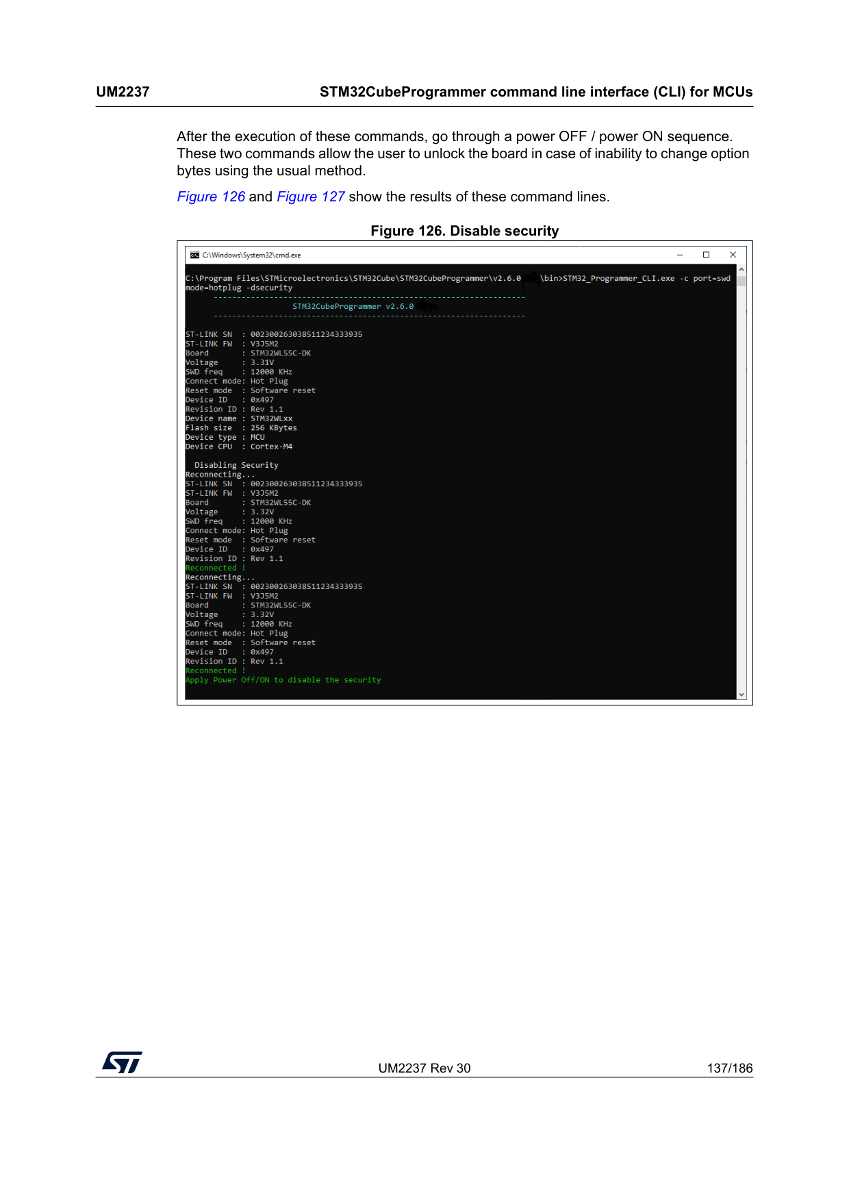
UM2237 Rev 30 137/186
Um2237
STM32CubeProgrammer command line interface (CLI) for MCUs 185 After the execution of these commands, go through a power OFF / power ON sequence. These two commands allow the user to unlock the board in case of inability to change option bytes using the usual method. Figure 126 and Figure 127 show the results of these command lines. Figure 126. Disable security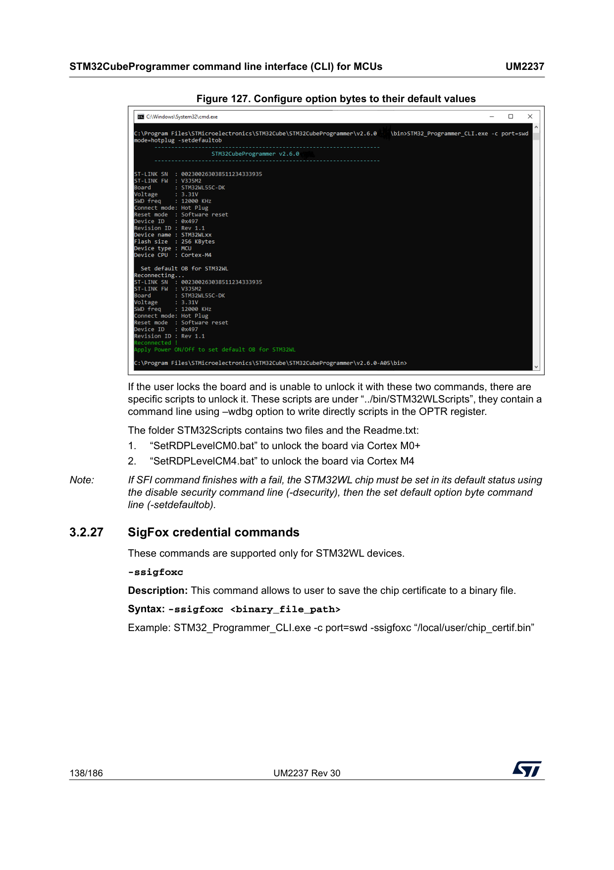
STM32CubeProgrammer command line interface (CLI) for MCUs
Um2237
138/186 UM2237 Rev 30 Figure 127. Configure option bytes to their default values If the user locks the board and is unable to unlock it with these two commands, there are specific scripts to unlock it. These scripts are under “../bin/STM32WLScripts”, they contain a command line using –wdbg option to write directly scripts in the OPTR register. The folder STM32Scripts contains two files and the Readme.txt: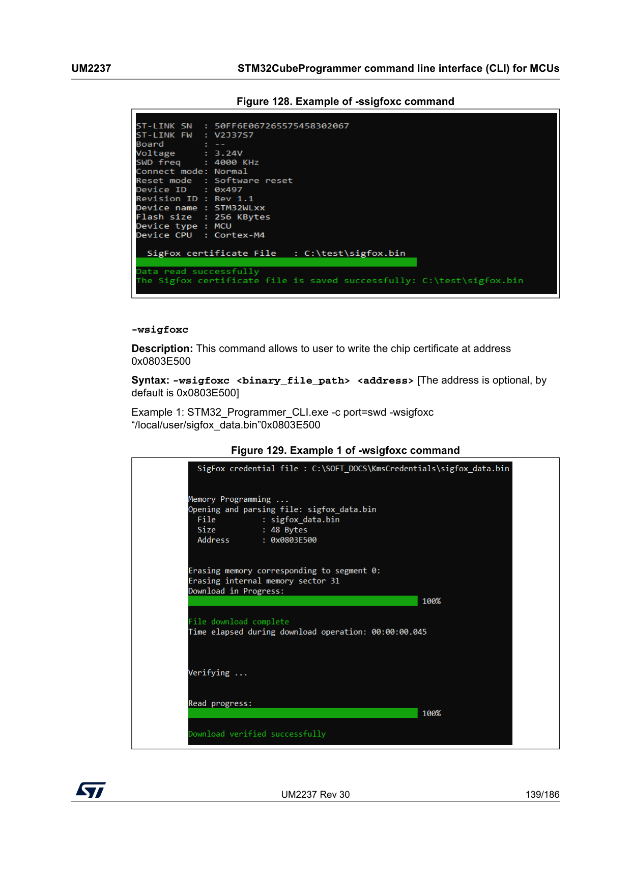
UM2237 Rev 30 139/186
Um2237
STM32CubeProgrammer command line interface (CLI) for MCUs 185 Figure 128. Example of -ssigfoxc command -wsigfoxc Description: This command allows to user to write the chip certificate at address 0x0803E500 Syntax: -wsigfoxc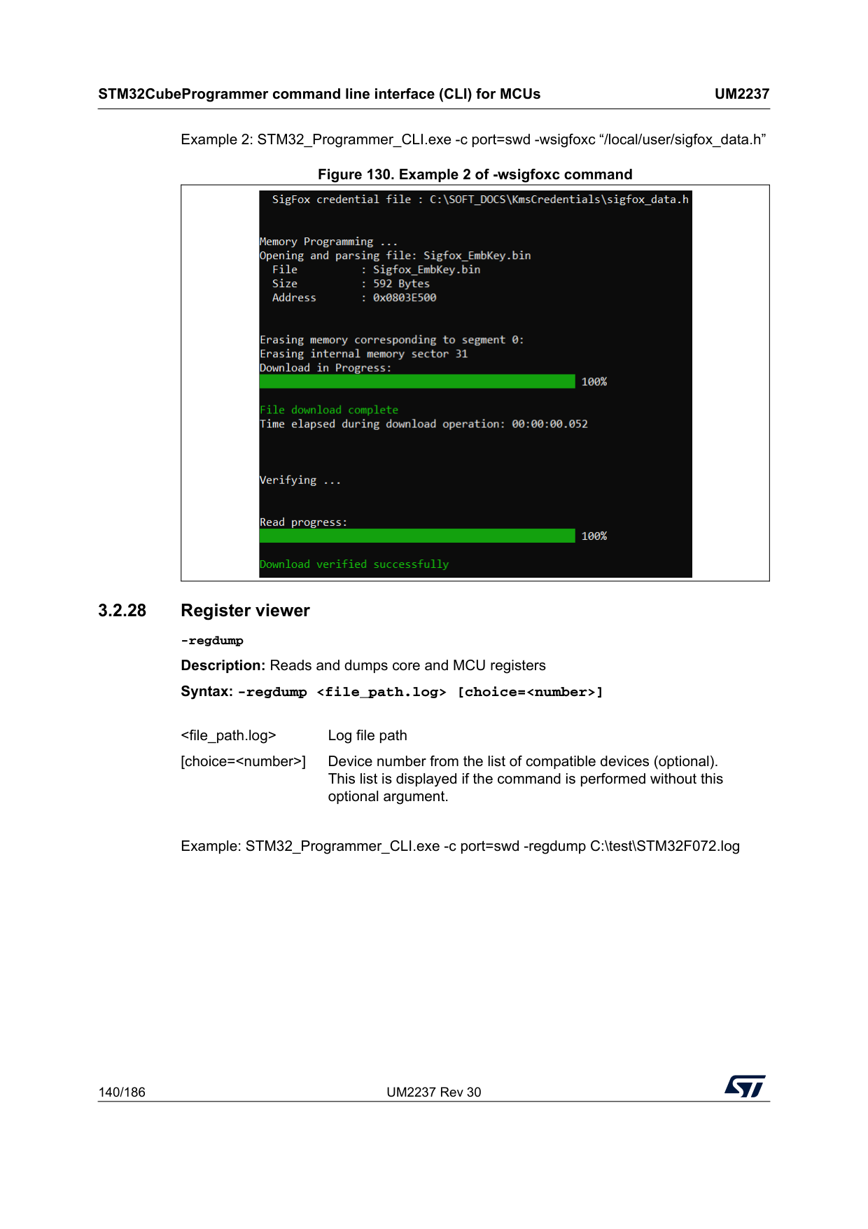
STM32CubeProgrammer command line interface (CLI) for MCUs
Um2237
140/186 UM2237 Rev 30 Example 2: STM32_Programmer_CLI.exe -c port=swd -wsigfoxc “/local/user/sigfox_data.h” Figure 130. Example 2 of -wsigfoxc command 3.2.28 Register viewer -regdump Description: Reads and dumps core and MCU registers Syntax: -regdumpExample: STM32_Programmer_CLI.exe -c port=swd -regdump C:\test\STM32F072.log
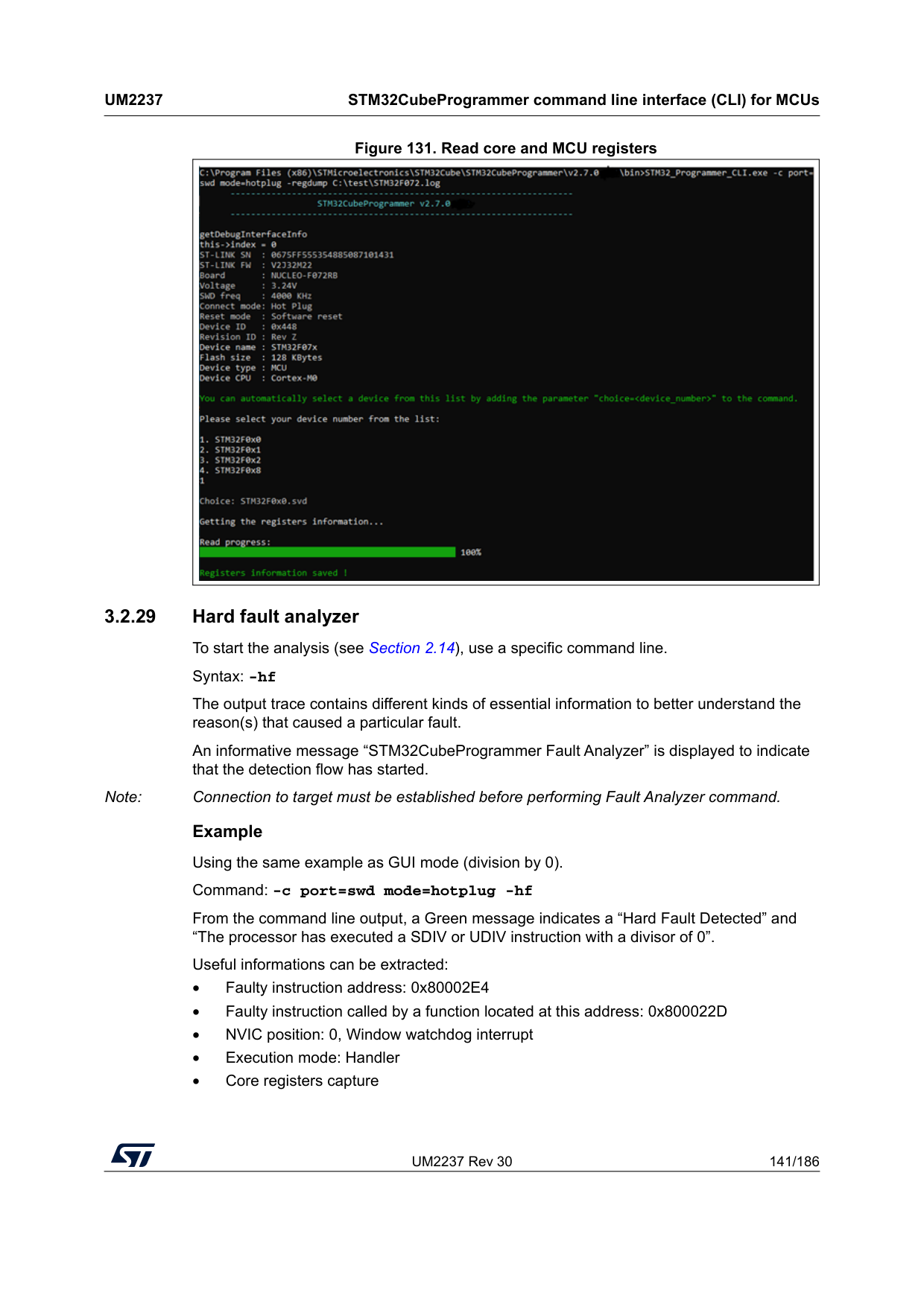
UM2237 Rev 30 141/186
Um2237
STM32CubeProgrammer command line interface (CLI) for MCUs 185 Figure 131. Read core and MCU registers 3.2.29 Hard fault analyzer To start the analysis (see Section 2.14), use a specific command line. Syntax: -hf The output trace contains different kinds of essential information to better understand the reason(s) that caused a particular fault. An informative message “STM32CubeProgrammer Fault Analyzer” is displayed to indicate that the detection flow has started. Note: Connection to target must be established before performing Fault Analyzer command. Example Using the same example as GUI mode (division by 0). Command: -c port=swd mode=hotplug -hf From the command line output, a Green message indicates a “Hard Fault Detected” and “The processor has executed a SDIV or UDIV instruction with a divisor of 0”. Useful informations can be extracted: • Faulty instruction address: 0x80002E4 • Faulty instruction called by a function located at this address: 0x800022D • NVIC position: 0, Window watchdog interrupt • Execution mode: Handler • Core registers capture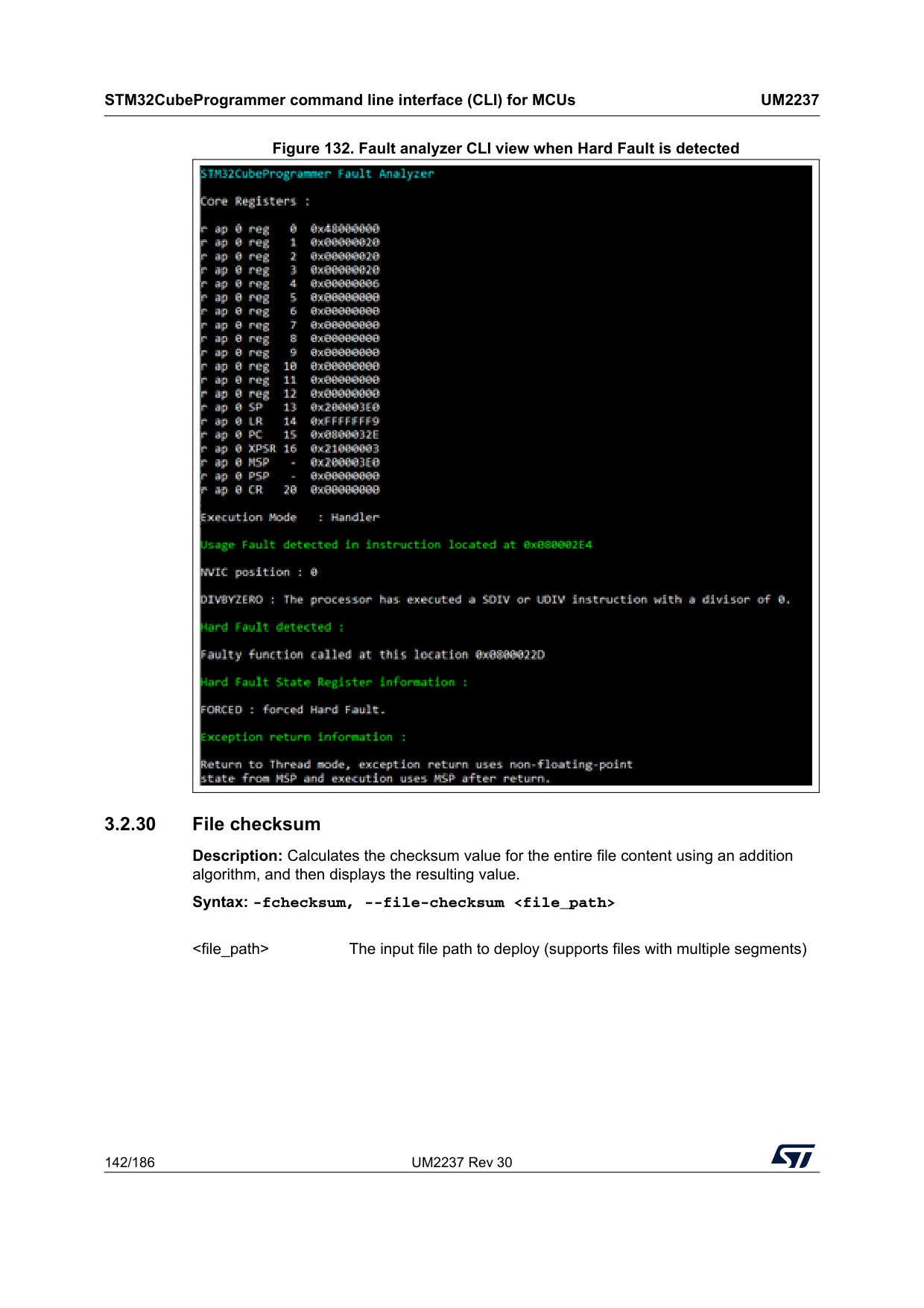
STM32CubeProgrammer command line interface (CLI) for MCUs
Um2237
142/186 UM2237 Rev 30 Figure 132. Fault analyzer CLI view when Hard Fault is detected 3.2.30 File checksum Description: Calculates the checksum value for the entire file content using an addition algorithm, and then displays the resulting value. Syntax: -fchecksum, --file-checksum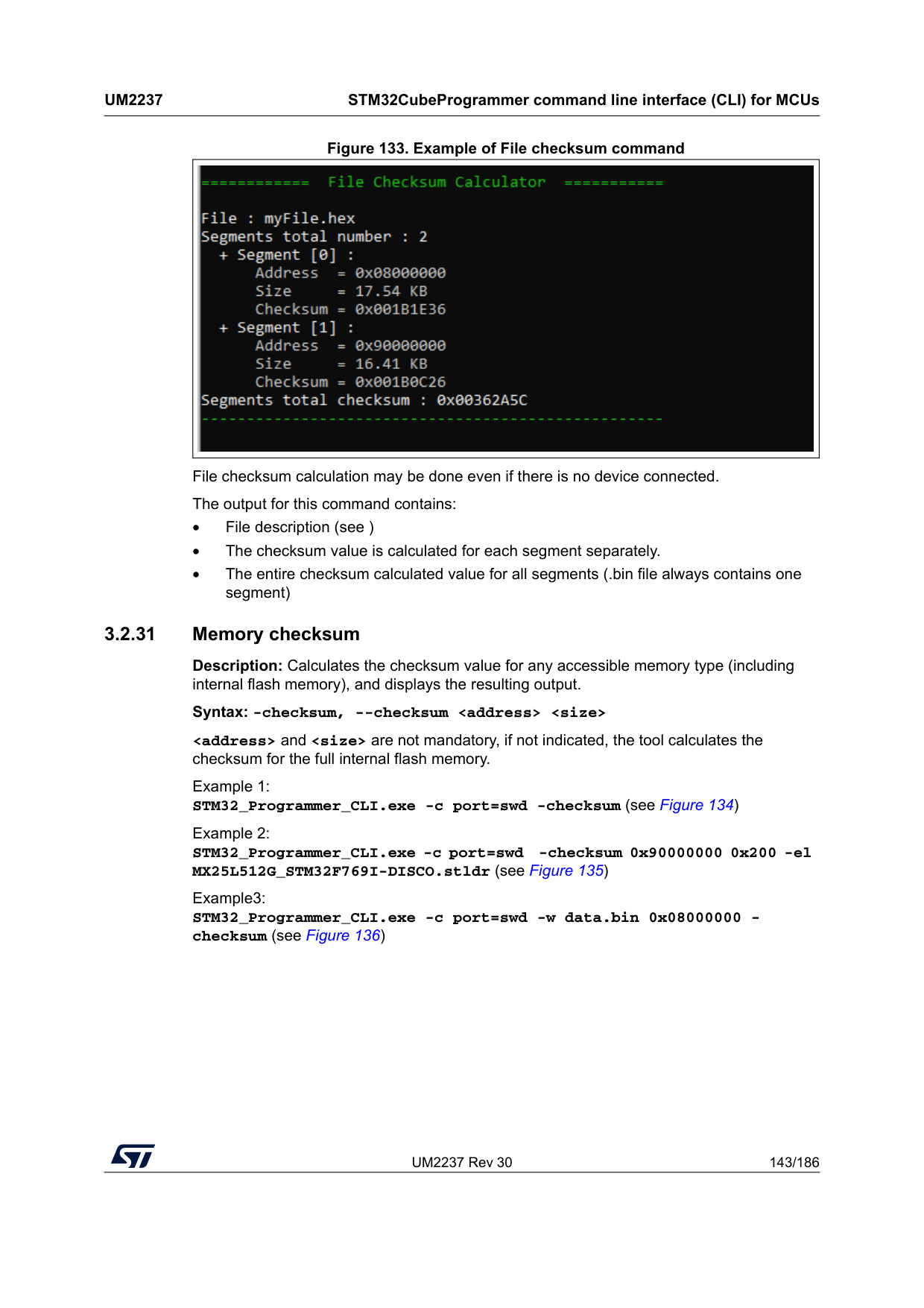
UM2237 Rev 30 143/186
Um2237
STM32CubeProgrammer command line interface (CLI) for MCUs 185 Figure 133. Example of File checksum command File checksum calculation may be done even if there is no device connected. The output for this command contains: • File description (see ) • The checksum value is calculated for each segment separately. • The entire checksum calculated value for all segments (.bin file always contains one segment) 3.2.31 Memory checksum Description: Calculates the checksum value for any accessible memory type (including internal flash memory), and displays the resulting output. Syntax: -checksum, --checksum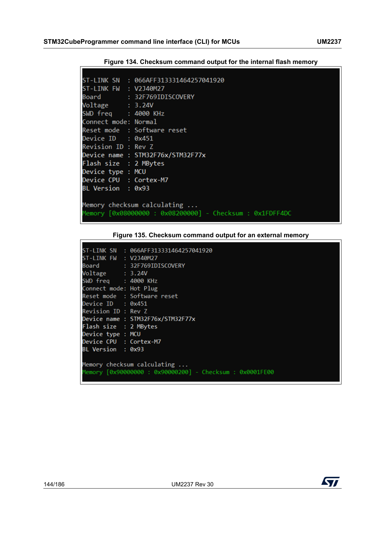
STM32CubeProgrammer command line interface (CLI) for MCUs
Um2237
144/186 UM2237 Rev 30 Figure 134. Checksum command output for the internal flash memory Figure 135. Checksum command output for an external memory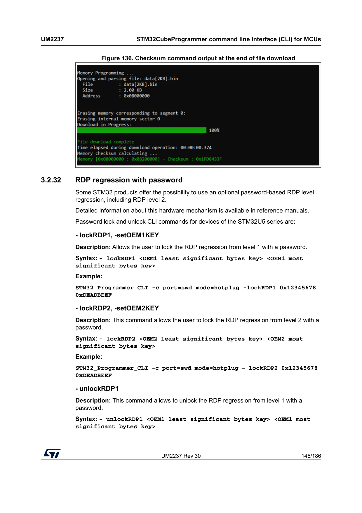
UM2237 Rev 30 145/186
Um2237
STM32CubeProgrammer command line interface (CLI) for MCUs 185 Figure 136. Checksum command output at the end of file download 3.2.32 RDP regression with password Some STM32 products offer the possibility to use an optional password-based RDP level regression, including RDP level 2. Detailed information about this hardware mechanism is available in reference manuals. Password lock and unlock CLI commands for devices of the STM32U5 series are:
STM32CubeProgrammer command line interface (CLI) for MCUs
Um2237
146/186 UM2237 Rev 30 Example: STM32_Programmer_CLI -c port=swd mode=hotplug -unlockRDP1 0x12345678 0xDEADBEEF
UM2237 Rev 30 147/186
Um2237
STM32CubeProgrammer command line interface (CLI) for MCUs 185 Syntax: -lockbs
STM32CubeProgrammer command line interface (CLI) for MCUs
Um2237
148/186 UM2237 Rev 30 Syntax: - unlockRDP2Example: /STM32_Programmer_CLI.exe -c port=swd mode=hotplug -sdp "C:\Program Files\STMicroelectronics\STM32Cube\STM32CubeProgrammer_DA_password\bin\DA_ Default_Config\NonCrypto\DA_Config_Certificate.obk" [OBKey_File_Path.obk] Path of OBK file
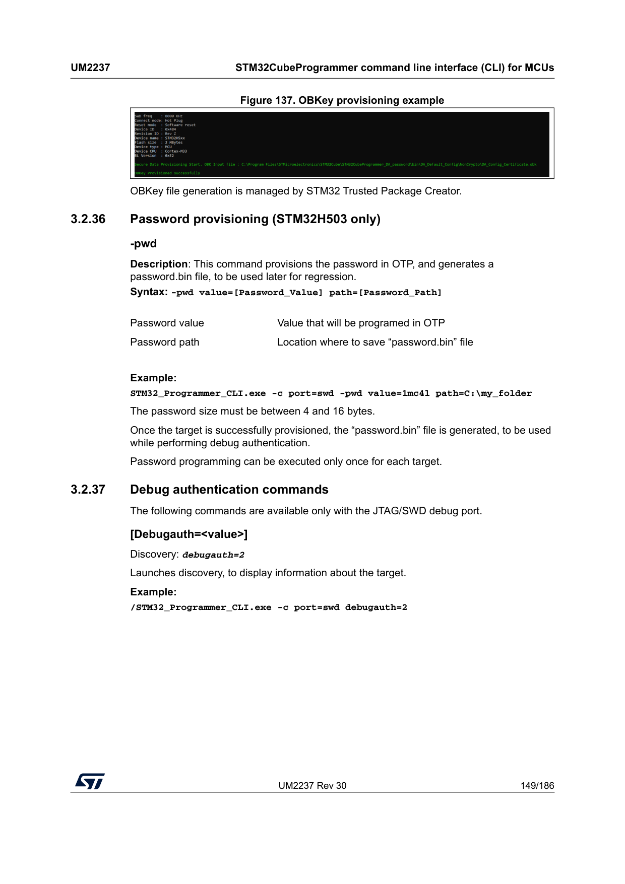
UM2237 Rev 30 149/186
Um2237
STM32CubeProgrammer command line interface (CLI) for MCUs 185 Figure 137. OBKey provisioning example OBKey file generation is managed by STM32 Trusted Package Creator. 3.2.36 Password provisioning (STM32H503 only) -pwd Description: This command provisions the password in OTP, and generates a password.bin file, to be used later for regression. Syntax: -pwd value=[Password_Value] path=[Password_Path]Example: STM32_Programmer_CLI.exe -c port=swd -pwd value=1mc4l path=C:\my_folder The password size must be between 4 and 16 bytes. Once the target is successfully provisioned, the “password.bin” file is generated, to be used while performing debug authentication. Password programming can be executed only once for each target. 3.2.37 Debug authentication commands The following commands are available only with the JTAG/SWD debug port. [Debugauth=
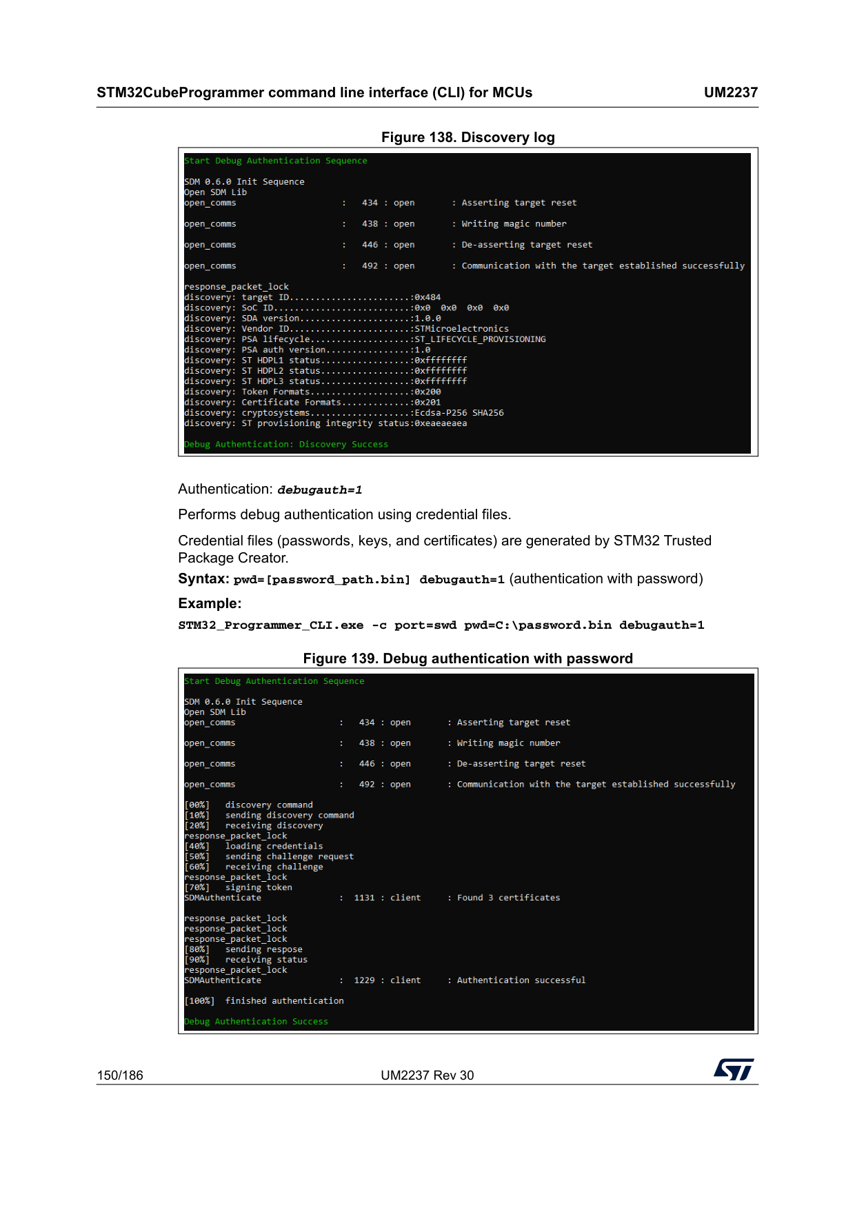
STM32CubeProgrammer command line interface (CLI) for MCUs
Um2237
150/186 UM2237 Rev 30 Figure 138. Discovery log Authentication: debugauth=1 Performs debug authentication using credential files. Credential files (passwords, keys, and certificates) are generated by STM32 Trusted Package Creator. Syntax: pwd=[password_path.bin] debugauth=1 (authentication with password) Example: STM32_Programmer_CLI.exe -c port=swd pwd=C:\password.bin debugauth=1 Figure 139. Debug authentication with password
UM2237 Rev 30 151/186
Um2237
STM32CubeProgrammer command line interface (CLI) for MCUs 185 Syntax: per=[Permission] key=[Key_Path.pem] cert=[Certificate_Path.b64] debugauth=1 (authentication with certificate) Permission selection • Permissions or actions must be identified using either letters or bit numbers. • To set the permission field (“per” in command line) with the correct permission/actions you must find the complete list of identifiers using one of the following options: – Use the discovery menu using debugauth=2. – Launch debug authentication using debugauth=1 without choosing permissions. This displays the available permissions, and the "per" field will be requested during runtime. Full regression example (single permission) • Letter identifier: – Format: per=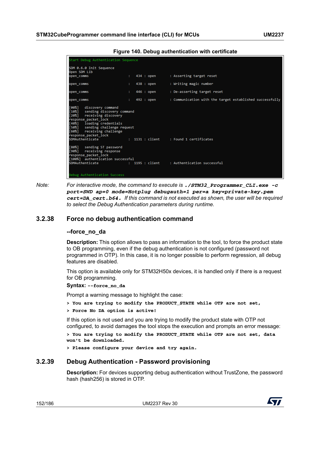
STM32CubeProgrammer command line interface (CLI) for MCUs
Um2237
152/186 UM2237 Rev 30 Figure 140. Debug authentication with certificate Note: For interactive mode, the command to execute is ./STM32_Programmer_CLI.exe -c port=SWD ap=0 mode=Hotplug debugauth=1 per=a key=private-key.pem cert=DA_cert.b64. If this command is not executed as shown, the user will be required to select the Debug Authentication parameters during runtime. 3.2.38 Force no debug authentication command --force_no_da Description: This option allows to pass an information to the tool, to force the product state to OB programming, even if the debug authentication is not configured (password not programmed in OTP). In this case, it is no longer possible to perform regression, all debug features are disabled. This option is available only for STM32H50x devices, it is handled only if there is a request for OB programming. Syntax: --force_no_da Prompt a warning message to highlight the case: > You are trying to modify the PRODUCT_STATE while OTP are not set, > Force No DA option is active! If this option is not used and you are trying to modify the product state with OTP not configured, to avoid damages the tool stops the execution and prompts an error message: > You are trying to modify the PRODUCT_STATE while OTP are not set, data won't be downloaded. > Please configure your device and try again. 3.2.39 Debug Authentication - Password provisioning Description: For devices supporting debug authentication without TrustZone, the password hash (hash256) is stored in OTP.
UM2237 Rev 30 153/186
Um2237
STM32CubeProgrammer command line interface (CLI) for MCUs 185 This command allows password provisioning, to do it enter a password value and a password path. Once the OTP is written, the corresponding OTP block is locked. The password value is used to calculate the hash to store in OTP. The password path is the location where to save “password.bin” file, needed to open the device in a Debug Authentication sequence. Syntax: -pwd value=Example: -pwd value=12345 path=“C:\Users\User_name\my_folder” The password size must be between 4 and 16 bytes. Password provisioning can be performed only when product state is provisioning, and only once for each device. 3.2.40 Debug authentication - Close debug For devices supporting debug authentication with TrustZone, the user can close the debug after performing Debug opening (instead of powering off/on the target). Syntax: debugauth=3 Example: STM32_Programmer_CLI.exe -c port=swd debugauth=3 3.2.41 Secure Manager - Install and update module In devices that support Secure Manager, it is possible to install and update a module, with HSM (hardware security module), or with a global license. Syntax: installipmodule [file_path] [hsm=0|1] [slot=slotID] [address]
Install module with HSM (product specific) Example: STM32_Programmer_CLI.exe -c port=swd mode=hotplug ap=1 -installipmodule C:\Users\User\module_chip_specific.smu HSM=1 1 0x8174000 If the sequence ends successfully, IP Module install done successfully is displayed.
STM32CubeProgrammer command line interface (CLI) for MCUs
Um2237
154/186 UM2237 Rev 30 Install module without HSM (global license) Example: STM32_Programmer_CLI.exe -c port=swd mode=hotplug ap=1 - installipmodule C:\Users\User\module_Global_License.smu HSM=0 C:\ C:\Users\User\License.bin 0x08000000 If the sequence ends successfully, IP Module install done successfully is displayed. Update module Syntax: updateipmoduleExample: STM32_Programmer_CLI.exe -c port=swd mode=hotplug ap=1 -updateipmodule C:\Users\User\module_update.smu 0x8174000 If the sequence ends successfully, IP update install done successfully is displayed. 3.2.42 SkipErase command --skiperase Description: Skips sector erase before programming Syntax: exe --skiperase Example: STM32_Programmer_CLI.exe –c port=swd -–skipErase -d C:\example.bin 0x08000000 3.2.43 OTP store command --storekeyotp, --storekeyotp Description: Stores authentication public key in the OTP. Applies only to STM32WB0x and STM32WL33 devices. This command can be performed only with UART interface. Syntax: -storekeyotp
Example: STM32_Programmer_CLI.exe -c port=COM41 br=115200 p=none -storekeyotp "C:\file1.c" 0x10070800 3.2.44 Key wrapping command -rssekw -updateipmodule, --updateipmodule update ip module
UM2237 Rev 30 155/186
Um2237
STM32CubeProgrammer command line interface (CLI) for MCUs 185 Description: Allows the user to select the root secure services extension library for key wrapping (RSSeKW), and execute the wrapping of the private key provisioned or provided by the user under specific configuration. Syntax: -rssekw3.2.45 OTP programming commands for STM32N6 For generic usage of this window refer to Section 5.1.12. STM32N6 devices support 367 OTP words, and the STM32CubeProgrammer allows users to program these OTP using the same commands as MPU or the user interface. • Via Debug interfaces: to program the OTP via ST-Link, use the external loader OTP_FUSES_STM32N6xx using the “-el” command. Example: -c port=swd -el
Then you can use OTP command described in Section 5.1.12. <.bin file_path> RSSe key wrapping file path <.bin file_path> Output .bin file path [KeyType=Ip
Offset Binary P
0x1 FSBL Binary none 0x0 OpenBootloader_STM32N6-DK_OTP_Cut2-Signed.stm32
STM32CubeProgrammer command line interface (CLI) for MCUs
Um2237
156/186 UM2237 Rev 30 3.2.46 External flash memory commands for STM32N6 STM32N6 devices can be connected via ST-Link (JTAG/SWD) and via BootROM (USB/UART). The external flash memory can be programmed in two ways: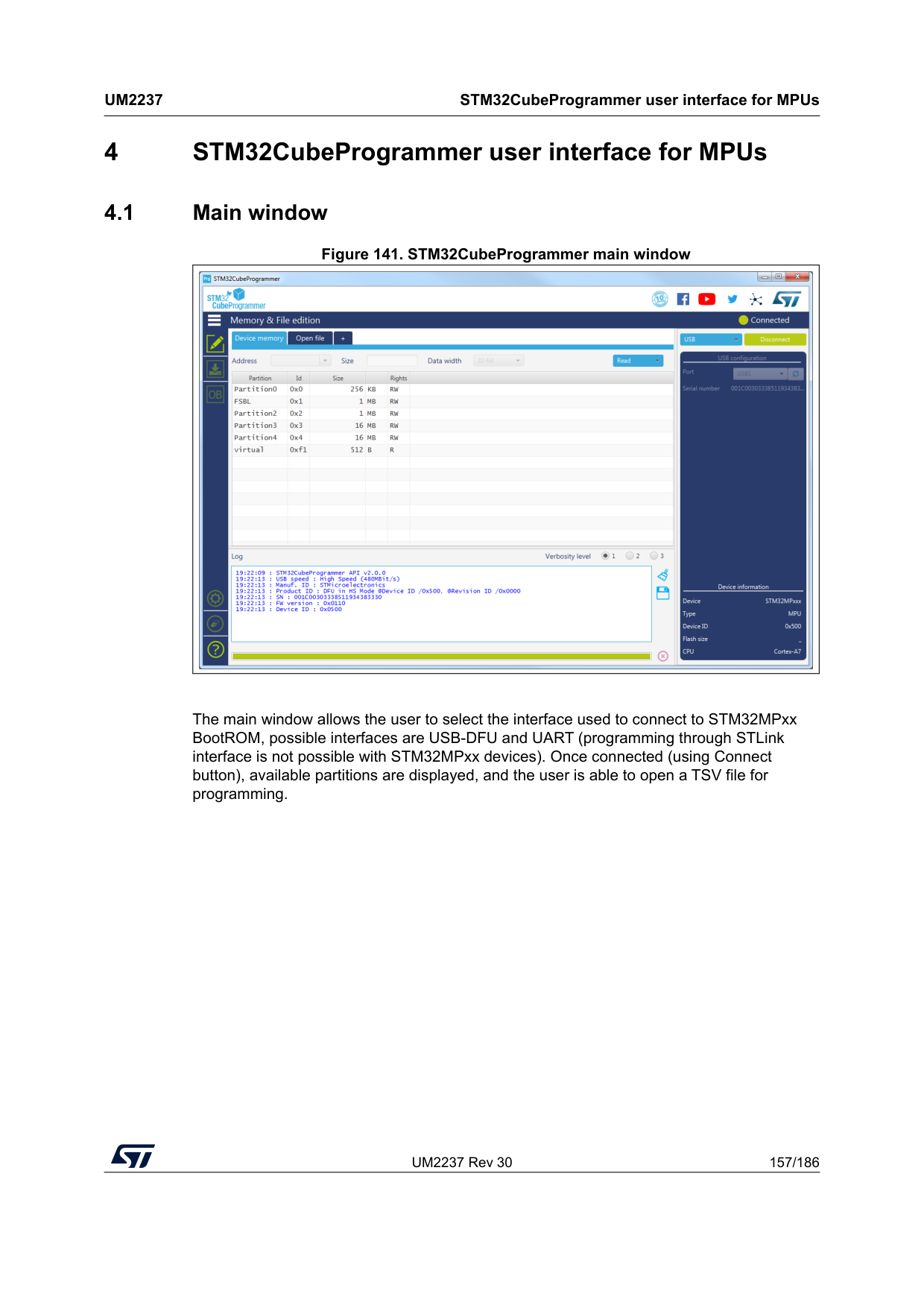
UM2237 Rev 30 157/186
Um2237
STM32CubeProgrammer user interface for MPUs 185 4 STM32CubeProgrammer user interface for MPUs 4.1 Main window Figure 141. STM32CubeProgrammer main window The main window allows the user to select the interface used to connect to STM32MPxx BootROM, possible interfaces are USB-DFU and UART (programming through STLink interface is not possible with STM32MPxx devices). Once connected (using Connect button), available partitions are displayed, and the user is able to open a TSV file for programming.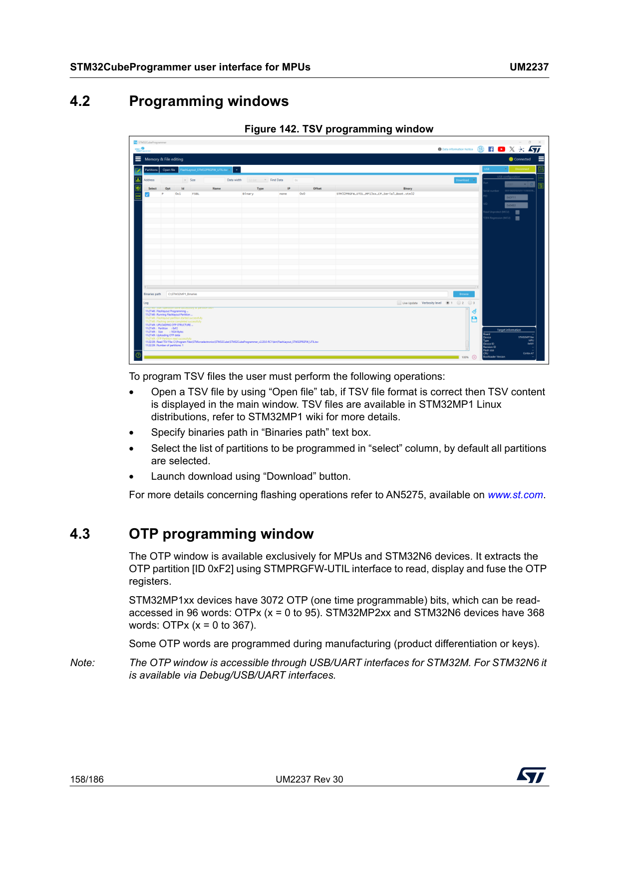
STM32CubeProgrammer user interface for MPUs
Um2237
158/186 UM2237 Rev 30 4.2 Programming windows Figure 142. TSV programming window To program TSV files the user must perform the following operations: • Open a TSV file by using “Open file” tab, if TSV file format is correct then TSV content is displayed in the main window. TSV files are available in STM32MP1 Linux distributions, refer to STM32MP1 wiki for more details. • Specify binaries path in “Binaries path” text box. • Select the list of partitions to be programmed in “select” column, by default all partitions are selected. • Launch download using “Download” button. For more details concerning flashing operations refer to AN5275, available on www.st.com. 4.3 OTP programming window The OTP window is available exclusively for MPUs and STM32N6 devices. It extracts the OTP partition [ID 0xF2] using STMPRGFW-UTIL interface to read, display and fuse the OTP registers. STM32MP1xx devices have 3072 OTP (one time programmable) bits, which can be read- accessed in 96 words: OTPx (x = 0 to 95). STM32MP2xx and STM32N6 devices have 368 words: OTPx (x = 0 to 367). Some OTP words are programmed during manufacturing (product differentiation or keys). Note: The OTP window is accessible through USB/UART interfaces for STM32M. For STM32N6 it is available via Debug/USB/UART interfaces.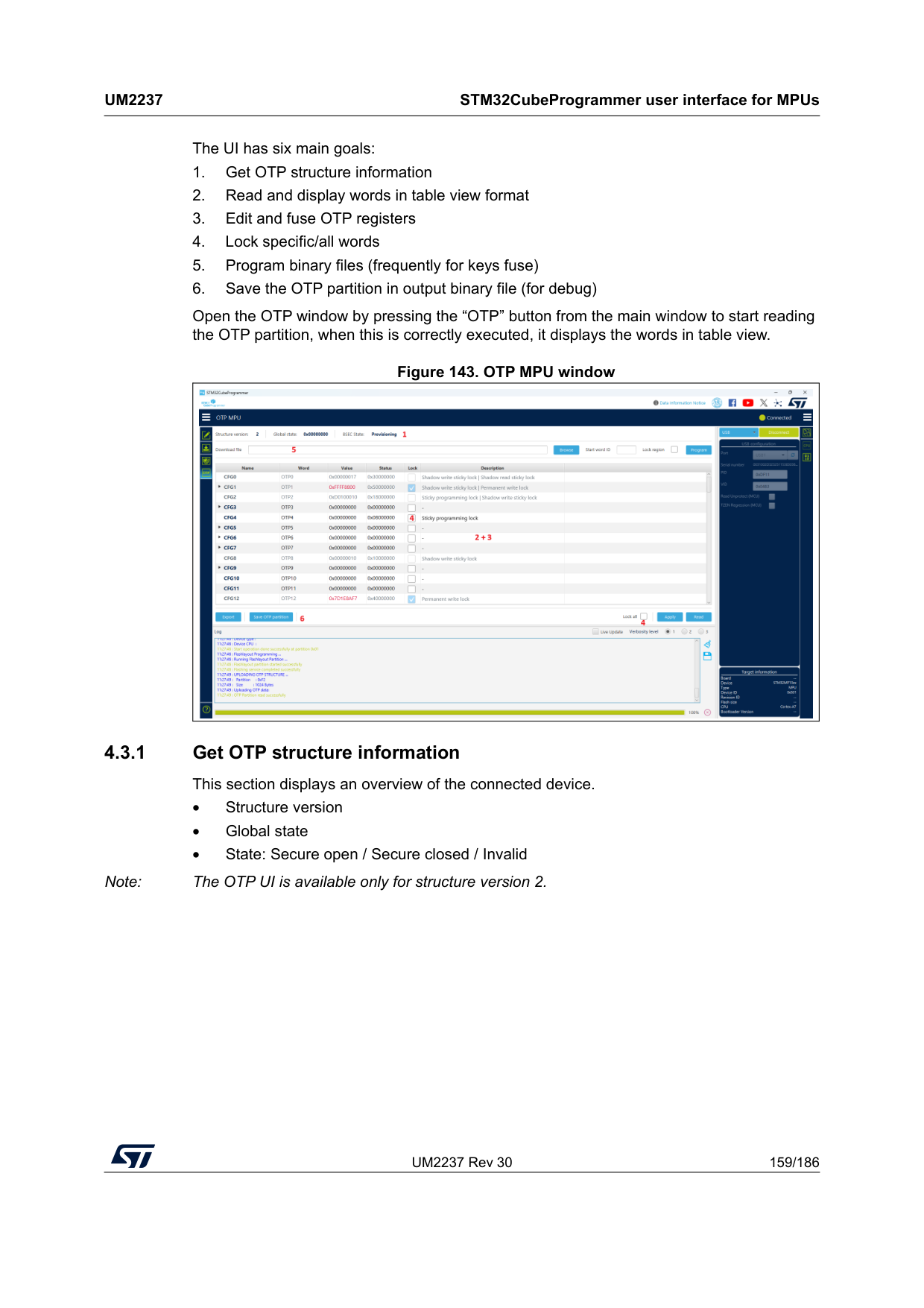
UM2237 Rev 30 159/186
Um2237
STM32CubeProgrammer user interface for MPUs 185 The UI has six main goals: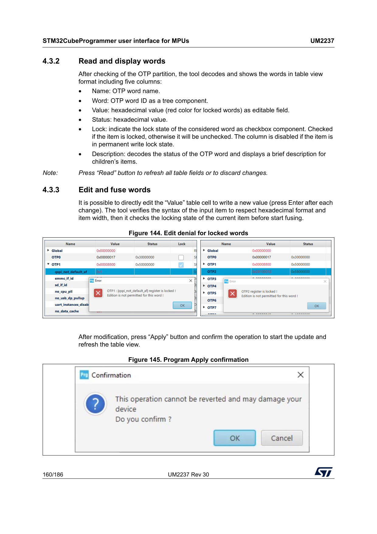
STM32CubeProgrammer user interface for MPUs
Um2237
160/186 UM2237 Rev 30 4.3.2 Read and display words After checking of the OTP partition, the tool decodes and shows the words in table view format including five columns: • Name: OTP word name. • Word: OTP word ID as a tree component. • Value: hexadecimal value (red color for locked words) as editable field. • Status: hexadecimal value. • Lock: indicate the lock state of the considered word as checkbox component. Checked if the item is locked, otherwise it will be unchecked. The column is disabled if the item is in permanent write lock state. • Description: decodes the status of the OTP word and displays a brief description for children’s items. Note: Press “Read” button to refresh all table fields or to discard changes. 4.3.3 Edit and fuse words It is possible to directly edit the “Value” table cell to write a new value (press Enter after each change). The tool verifies the syntax of the input item to respect hexadecimal format and item width, then it checks the locking state of the current item before start fusing. Figure 144. Edit denial for locked words After modification, press “Apply” button and confirm the operation to start the update and refresh the table view. Figure 145. Program Apply confirmation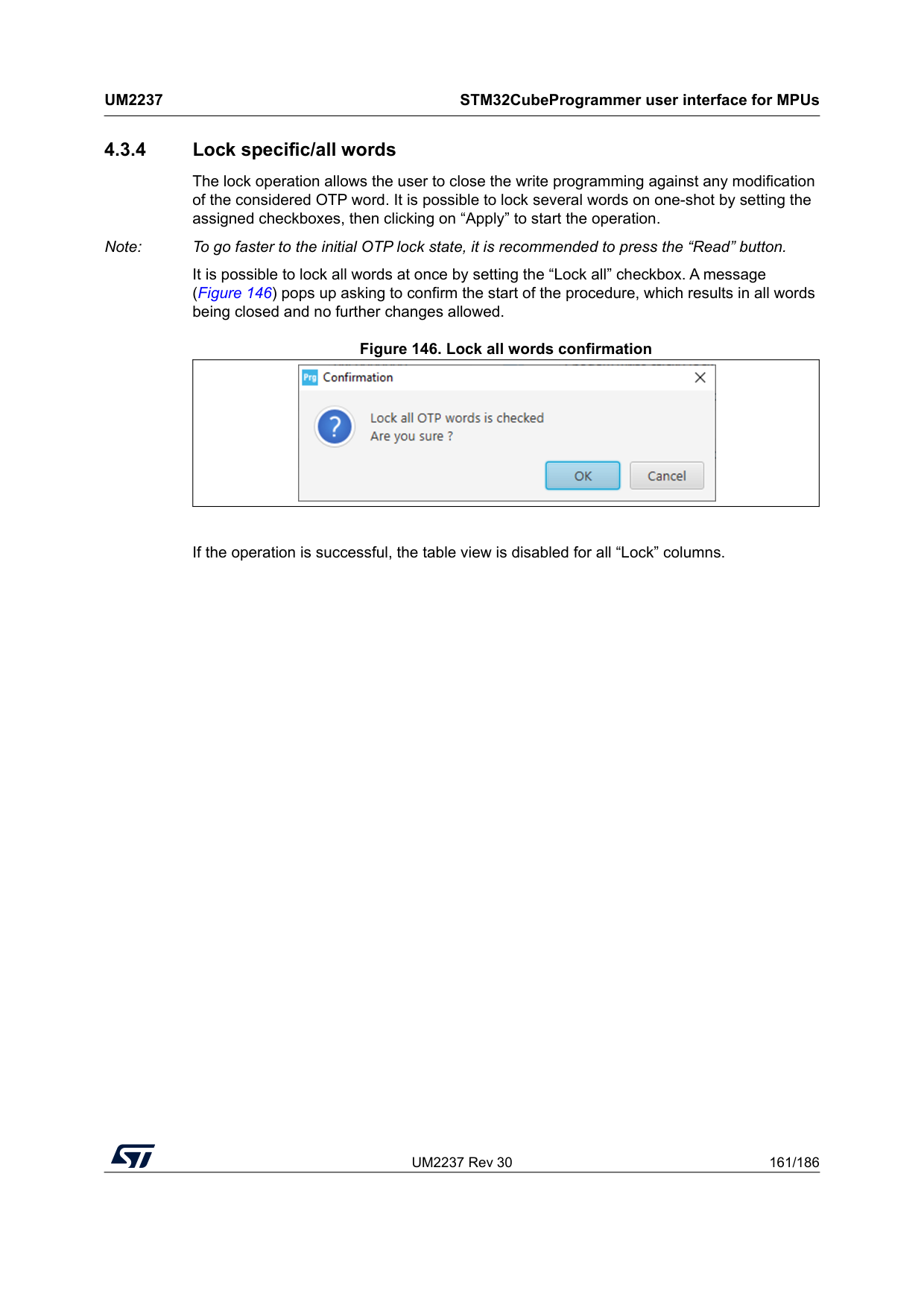
UM2237 Rev 30 161/186
Um2237
STM32CubeProgrammer user interface for MPUs 185 4.3.4 Lock specific/all words The lock operation allows the user to close the write programming against any modification of the considered OTP word. It is possible to lock several words on one-shot by setting the assigned checkboxes, then clicking on “Apply” to start the operation. Note: To go faster to the initial OTP lock state, it is recommended to press the “Read” button. It is possible to lock all words at once by setting the “Lock all” checkbox. A message (Figure 146) pops up asking to confirm the start of the procedure, which results in all words being closed and no further changes allowed. Figure 146. Lock all words confirmation If the operation is successful, the table view is disabled for all “Lock” columns.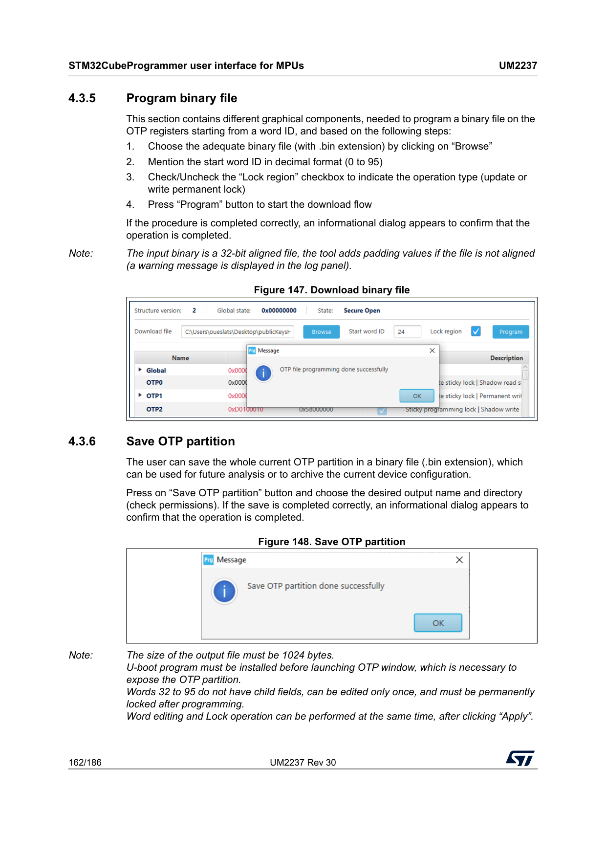
STM32CubeProgrammer user interface for MPUs
Um2237
162/186 UM2237 Rev 30 4.3.5 Program binary file This section contains different graphical components, needed to program a binary file on the OTP registers starting from a word ID, and based on the following steps: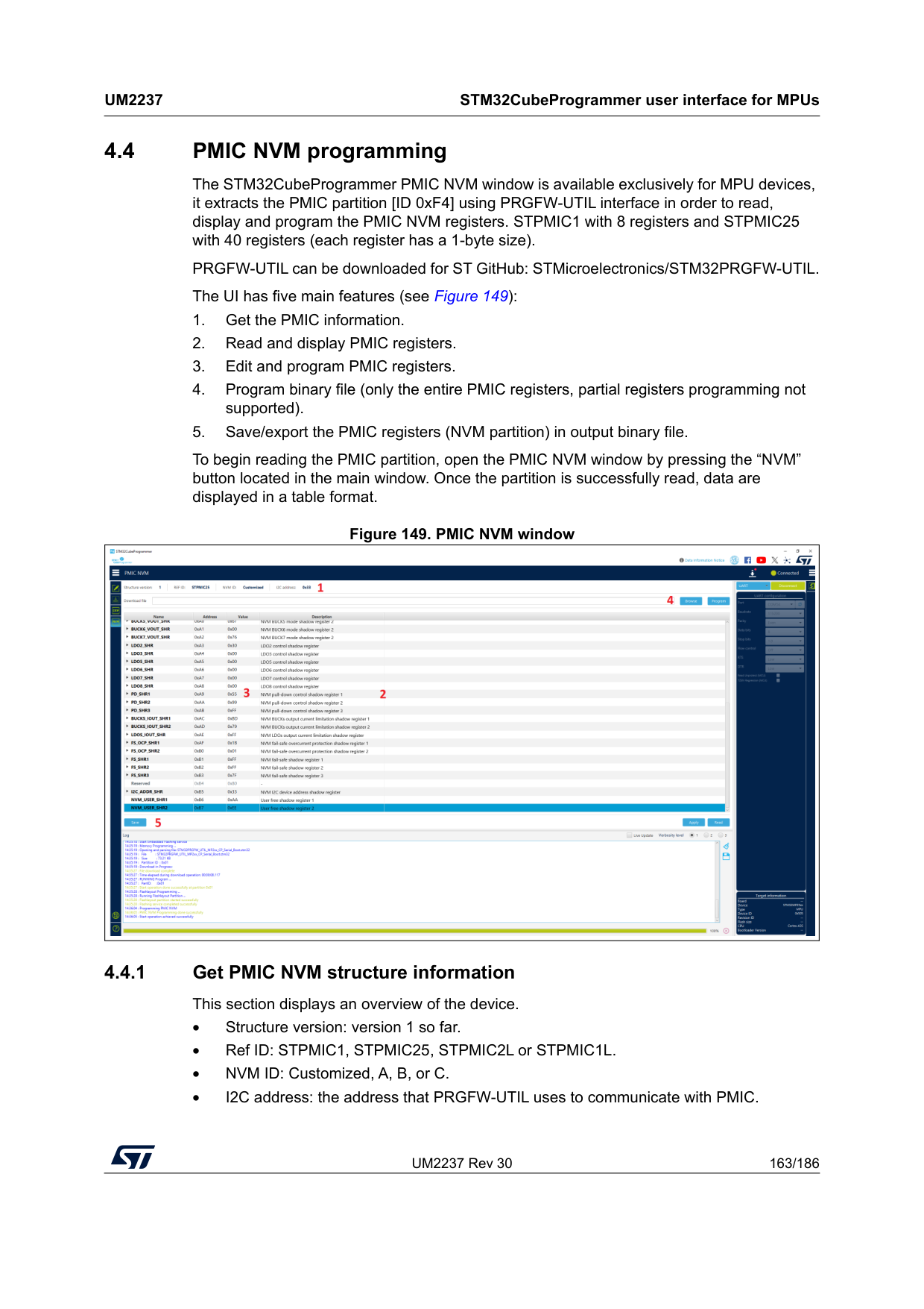
UM2237 Rev 30 163/186
Um2237
STM32CubeProgrammer user interface for MPUs 185 4.4 PMIC NVM programming The STM32CubeProgrammer PMIC NVM window is available exclusively for MPU devices, it extracts the PMIC partition [ID 0xF4] using PRGFW-UTIL interface in order to read, display and program the PMIC NVM registers. STPMIC1 with 8 registers and STPMIC25 with 40 registers (each register has a 1-byte size). PRGFW-UTIL can be downloaded for ST GitHub: STMicroelectronics/STM32PRGFW-UTIL. The UI has five main features (see Figure 149):
STM32CubeProgrammer user interface for MPUs
Um2237
164/186 UM2237 Rev 30 4.4.2 Read and display words After checking of the PMIC partition, the tool decodes and shows the words in table view format including four columns: • Name: NVM register name. • Address: hexadecimal value representing the address in the NVM. • Value: hexadecimal value (editable). • Description: displays the description of the register and its fields. Note: Press “Read” button to refresh all table fields or to discard changes. The value and name cells expose a tooltip message to add description (name, hex value, bin value representation). 4.4.3 Edit and program registers There is two ways to edit the Value of the register: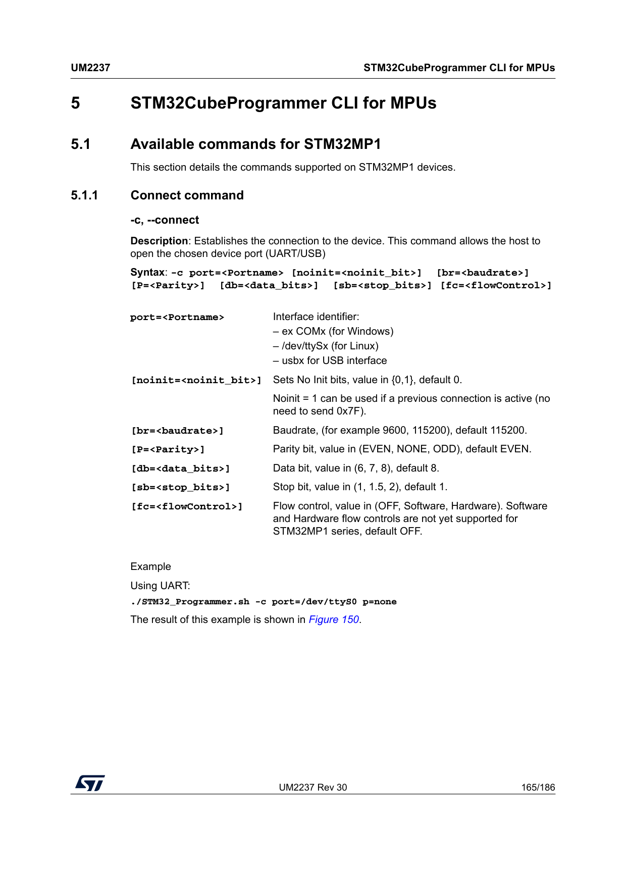
UM2237 Rev 30 165/186
Um2237
STM32CubeProgrammer CLI for MPUs 185 5 STM32CubeProgrammer CLI for MPUs 5.1 Available commands for STM32MP1 This section details the commands supported on STM32MP1 devices. 5.1.1 Connect command -c, --connect Description: Establishes the connection to the device. This command allows the host to open the chosen device port (UART/USB) Syntax: -c port=Example Using UART: ./STM32_Programmer.sh -c port=/dev/ttyS0 p=none The result of this example is shown in Figure 150. port=
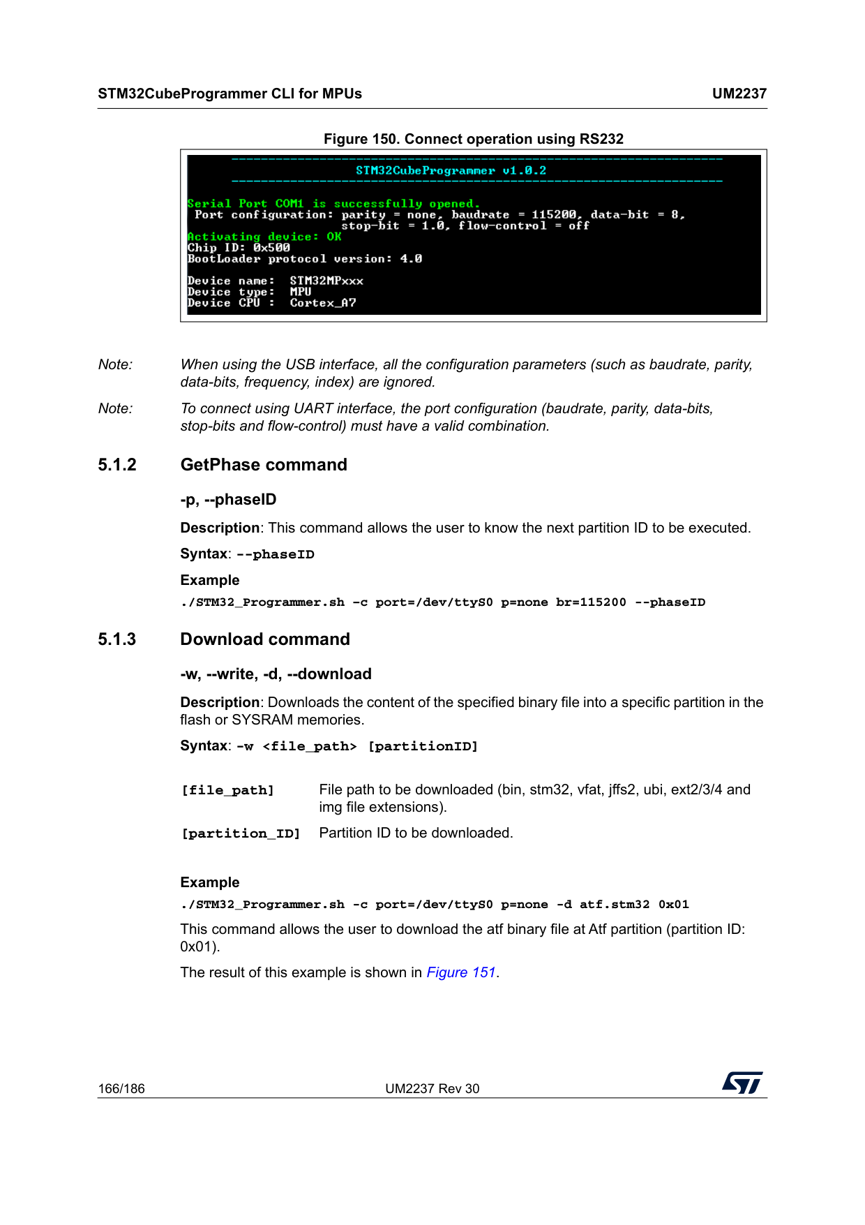
STM32CubeProgrammer CLI for MPUs
Um2237
166/186 UM2237 Rev 30 Figure 150. Connect operation using RS232 Note: When using the USB interface, all the configuration parameters (such as baudrate, parity, data-bits, frequency, index) are ignored. Note: To connect using UART interface, the port configuration (baudrate, parity, data-bits, stop-bits and flow-control) must have a valid combination. 5.1.2 GetPhase command -p, --phaseID Description: This command allows the user to know the next partition ID to be executed. Syntax: --phaseID Example ./STM32_Programmer.sh –c port=/dev/ttyS0 p=none br=115200 --phaseID 5.1.3 Download command -w, --write, -d, --download Description: Downloads the content of the specified binary file into a specific partition in the flash or SYSRAM memories. Syntax: -wExample ./STM32_Programmer.sh -c port=/dev/ttyS0 p=none -d atf.stm32 0x01 This command allows the user to download the atf binary file at Atf partition (partition ID: 0x01). The result of this example is shown in Figure 151. [file_path] File path to be downloaded (bin, stm32, vfat, jffs2, ubi, ext2/3/4 and img file extensions). [partition_ID] Partition ID to be downloaded.
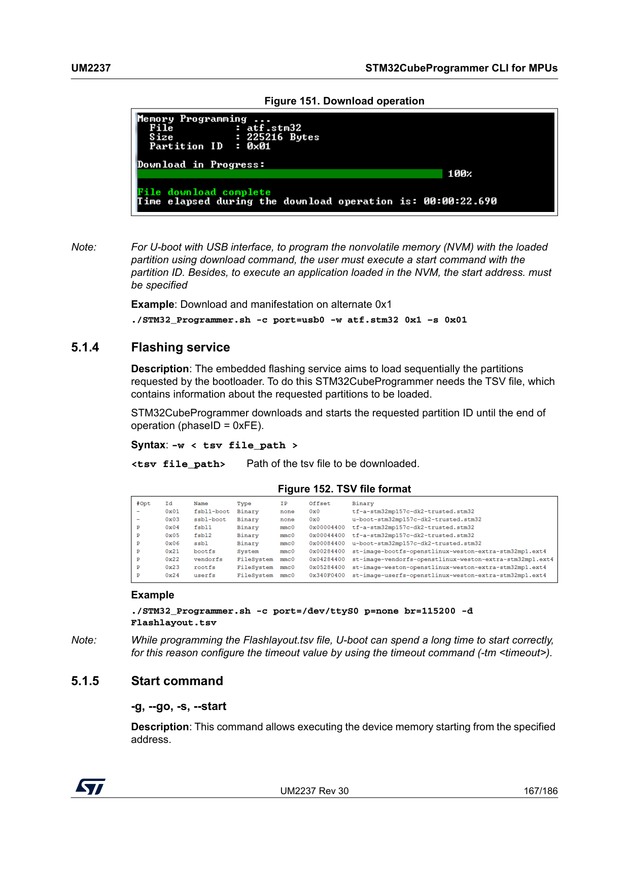
UM2237 Rev 30 167/186
Um2237
STM32CubeProgrammer CLI for MPUs 185 Figure 151. Download operation Note: For U-boot with USB interface, to program the nonvolatile memory (NVM) with the loaded partition using download command, the user must execute a start command with the partition ID. Besides, to execute an application loaded in the NVM, the start address. must be specified Example: Download and manifestation on alternate 0x1 ./STM32_Programmer.sh -c port=usb0 -w atf.stm32 0x1 –s 0x01 5.1.4 Flashing service Description: The embedded flashing service aims to load sequentially the partitions requested by the bootloader. To do this STM32CubeProgrammer needs the TSV file, which contains information about the requested partitions to be loaded. STM32CubeProgrammer downloads and starts the requested partition ID until the end of operation (phaseID = 0xFE). Syntax: -w < tsv file_path >
STM32CubeProgrammer CLI for MPUs
Um2237
168/186 UM2237 Rev 30 Syntax: --start [start_address/Partition_ID]Example ./STM32_Programmer.sh --connect port=/dev/ttyS0 p=none br=115200 --start 0x03 This command allows the user to run the code specified at partition 0x03. Note: For U-boot with USB interface, to program the NVM with the loaded partition using download command, you need to execute a start command with the partition ID. To execute an application loaded in the NVM, you need to specify the start address. Example 1: Download and manifestation on alternate 0x1 ./STM32_Programmer.sh -c port=usb0 -w atf.stm32 0x01 –s 0x01 Example 2: Execute code at a specific address ./STM32_Programmer.sh -c port=usb0 –s 0xC0000000 5.1.6 Read partition command -rp, --readPart Description: Reads and uploads the specified partition content into a specified binary file starting from an offset address. This command is supported only by U-boot. Syntax: --readPart
Example: ./STM32_Programmer.sh -c port=/dev/ttyS0 p=none br=115200 -rp 0x01 0x200 0x1000 readPart1.bin This command allows the user to read 0x1000 bytes from the sebl1 partition at offset address 0x200 and to upload its content to a binary file “readPart1.bin” 5.1.7 List command -l, -list Description: This command lists all available communication interfaces UART and USB. Syntax: -l, --list
UM2237 Rev 30 169/186
Um2237
STM32CubeProgrammer CLI for MPUs 185 Example: ./STM32_Programmer.sh –list uart 5.1.8 QuietMode command -q, --quietMode Description: This command disables the progress bar display during Download and Read partition commands. Syntax: -q, --quietMode Example: ./STM32_Programmer.sh –c port=/dev/ttyS0 p=none br=115200 --quietMode –w binaryPath.bin 0x01 5.1.9 Verbosity command -vb, --verbosity Description: This command allows the user to display more messages, to be more verbose. Syntax: -vb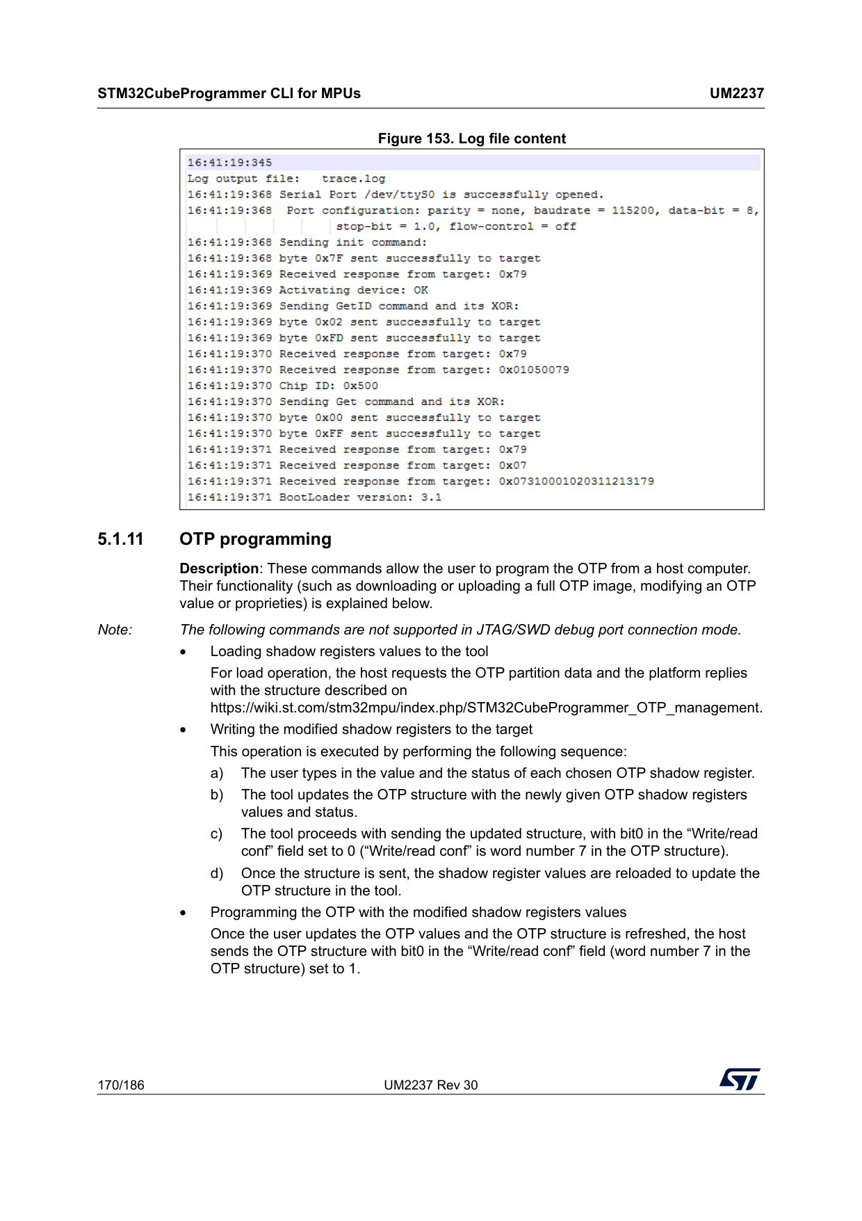
STM32CubeProgrammer CLI for MPUs
Um2237
170/186 UM2237 Rev 30 Figure 153. Log file content 5.1.11 OTP programming Description: These commands allow the user to program the OTP from a host computer. Their functionality (such as downloading or uploading a full OTP image, modifying an OTP value or proprieties) is explained below. Note: The following commands are not supported in JTAG/SWD debug port connection mode. • Loading shadow registers values to the tool For load operation, the host requests the OTP partition data and the platform replies with the structure described on https://wiki.st.com/stm32mpu/index.php/STM32CubeProgrammer_OTP_management. • Writing the modified shadow registers to the target This operation is executed by performing the following sequence: a) The user types in the value and the status of each chosen OTP shadow register. b) The tool updates the OTP structure with the newly given OTP shadow registers values and status. c) The tool proceeds with sending the updated structure, with bit0 in the “Write/read conf” field set to 0 (“Write/read conf” is word number 7 in the OTP structure). d) Once the structure is sent, the shadow register values are reloaded to update the OTP structure in the tool. • Programming the OTP with the modified shadow registers values Once the user updates the OTP values and the OTP structure is refreshed, the host sends the OTP structure with bit0 in the “Write/read conf” field (word number 7 in the OTP structure) set to 1.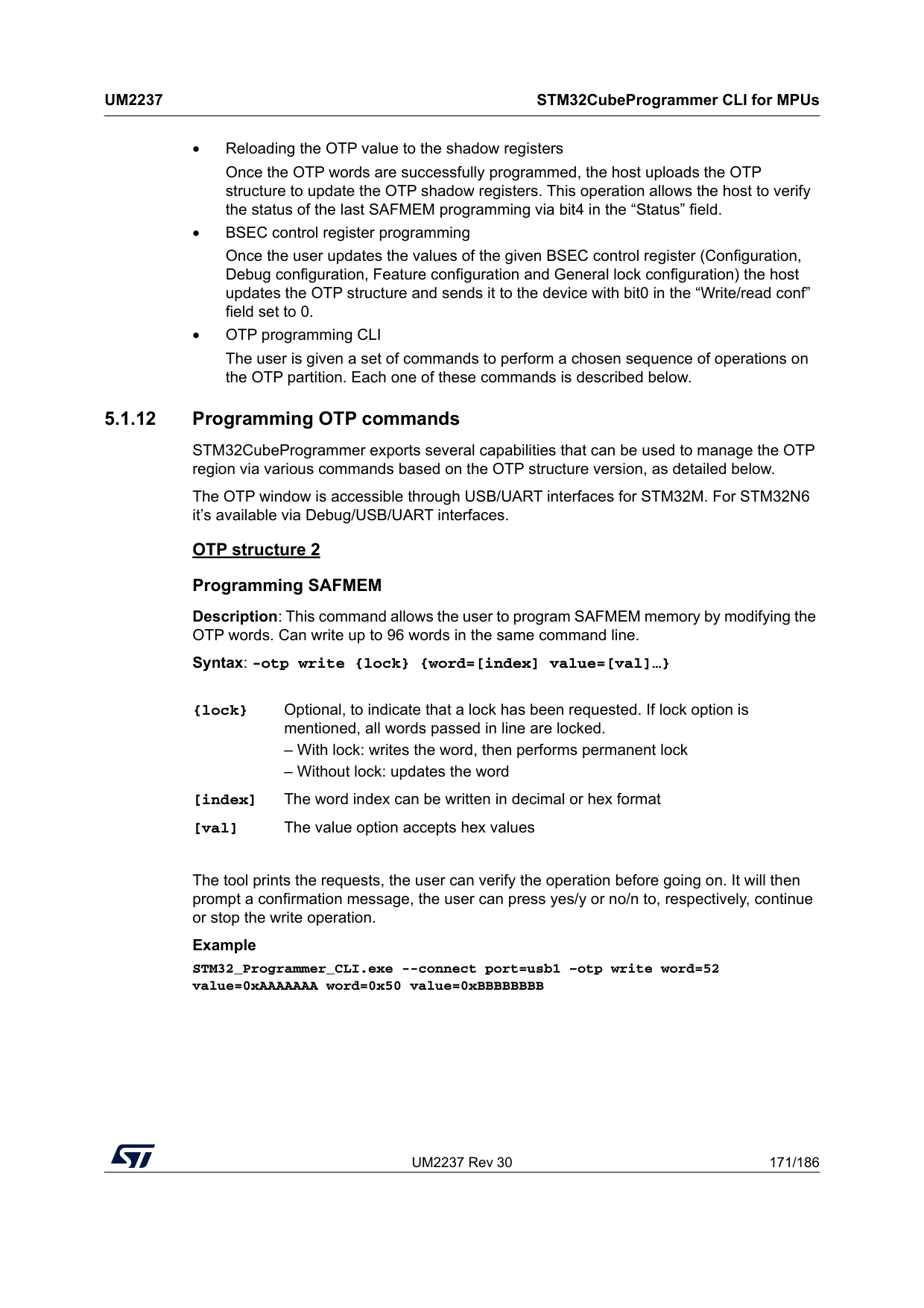
UM2237 Rev 30 171/186
Um2237
STM32CubeProgrammer CLI for MPUs 185 • Reloading the OTP value to the shadow registers Once the OTP words are successfully programmed, the host uploads the OTP structure to update the OTP shadow registers. This operation allows the host to verify the status of the last SAFMEM programming via bit4 in the “Status” field. • BSEC control register programming Once the user updates the values of the given BSEC control register (Configuration, Debug configuration, Feature configuration and General lock configuration) the host updates the OTP structure and sends it to the device with bit0 in the “Write/read conf” field set to 0. • OTP programming CLI The user is given a set of commands to perform a chosen sequence of operations on the OTP partition. Each one of these commands is described below. 5.1.12 Programming OTP commands STM32CubeProgrammer exports several capabilities that can be used to manage the OTP region via various commands based on the OTP structure version, as detailed below. The OTP window is accessible through USB/UART interfaces for STM32M. For STM32N6 it’s available via Debug/USB/UART interfaces. OTP structure 2 Programming SAFMEM Description: This command allows the user to program SAFMEM memory by modifying the OTP words. Can write up to 96 words in the same command line. Syntax: -otp write {lock} {word=[index] value=[val]…}The tool prints the requests, the user can verify the operation before going on. It will then prompt a confirmation message, the user can press yes/y or no/n to, respectively, continue or stop the write operation. Example STM32_Programmer_CLI.exe --connect port=usb1 –otp write word=52 value=0xAAAAAAA word=0x50 value=0xBBBBBBBB {lock} Optional, to indicate that a lock has been requested. If lock option is mentioned, all words passed in line are locked. – With lock: writes the word, then performs permanent lock – Without lock: updates the word [index] The word index can be written in decimal or hex format [val] The value option accepts hex values
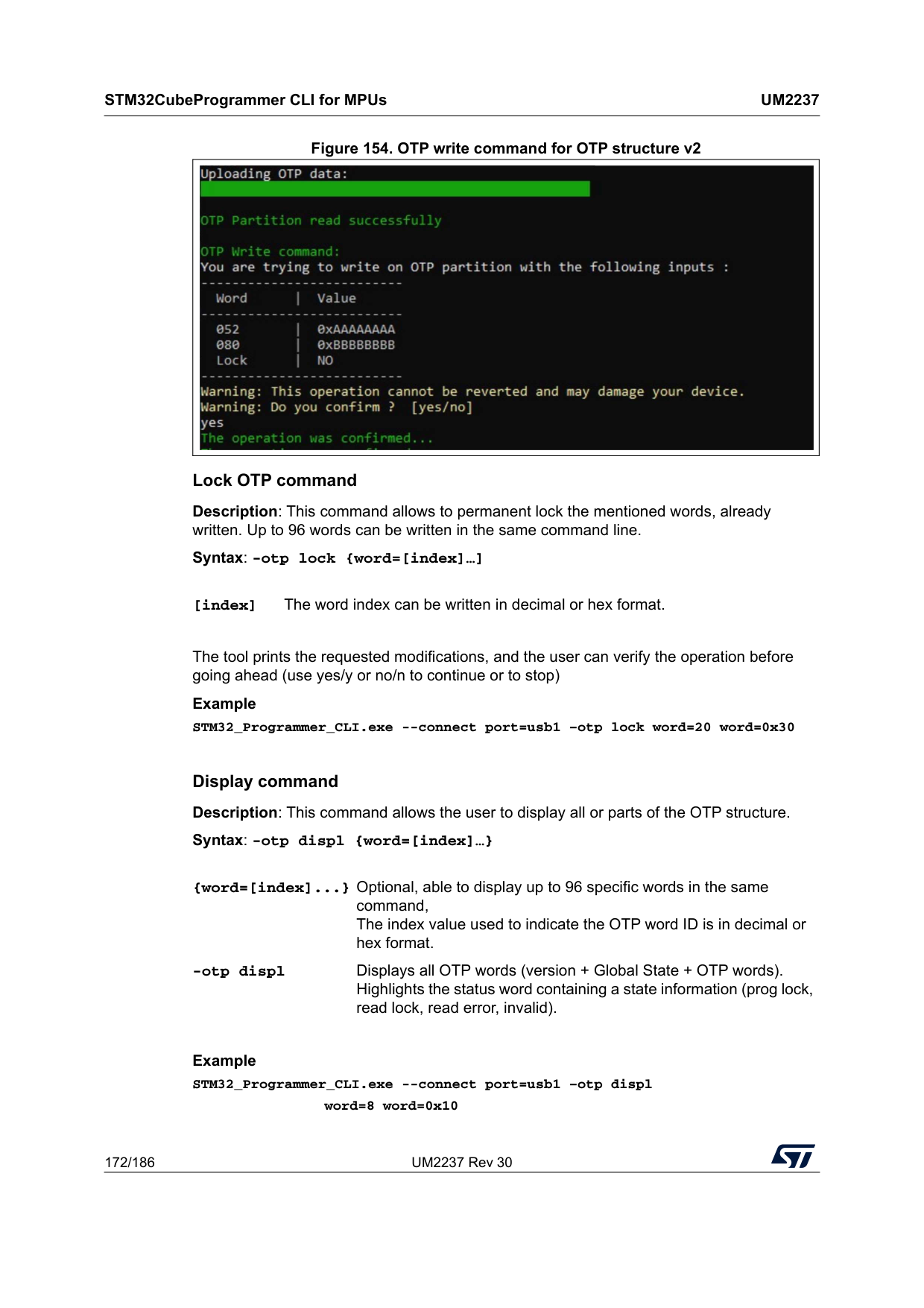
STM32CubeProgrammer CLI for MPUs
Um2237
172/186 UM2237 Rev 30 Figure 154. OTP write command for OTP structure v2 Lock OTP command Description: This command allows to permanent lock the mentioned words, already written. Up to 96 words can be written in the same command line. Syntax: -otp lock {word=[index]…]The tool prints the requested modifications, and the user can verify the operation before going ahead (use yes/y or no/n to continue or to stop) Example STM32_Programmer_CLI.exe --connect port=usb1 –otp lock word=20 word=0x30 Display command Description: This command allows the user to display all or parts of the OTP structure. Syntax: -otp displ {word=[index]…}
Example STM32_Programmer_CLI.exe --connect port=usb1 –otp displ
word=8 word=0x10 [index] The word index can be written in decimal or hex format. {word=[index]...} Optional, able to display up to 96 specific words in the same command, The index value used to indicate the OTP word ID is in decimal or hex format. -otp displ Displays all OTP words (version + Global State + OTP words). Highlights the status word containing a state information (prog lock, read lock, read error, invalid).
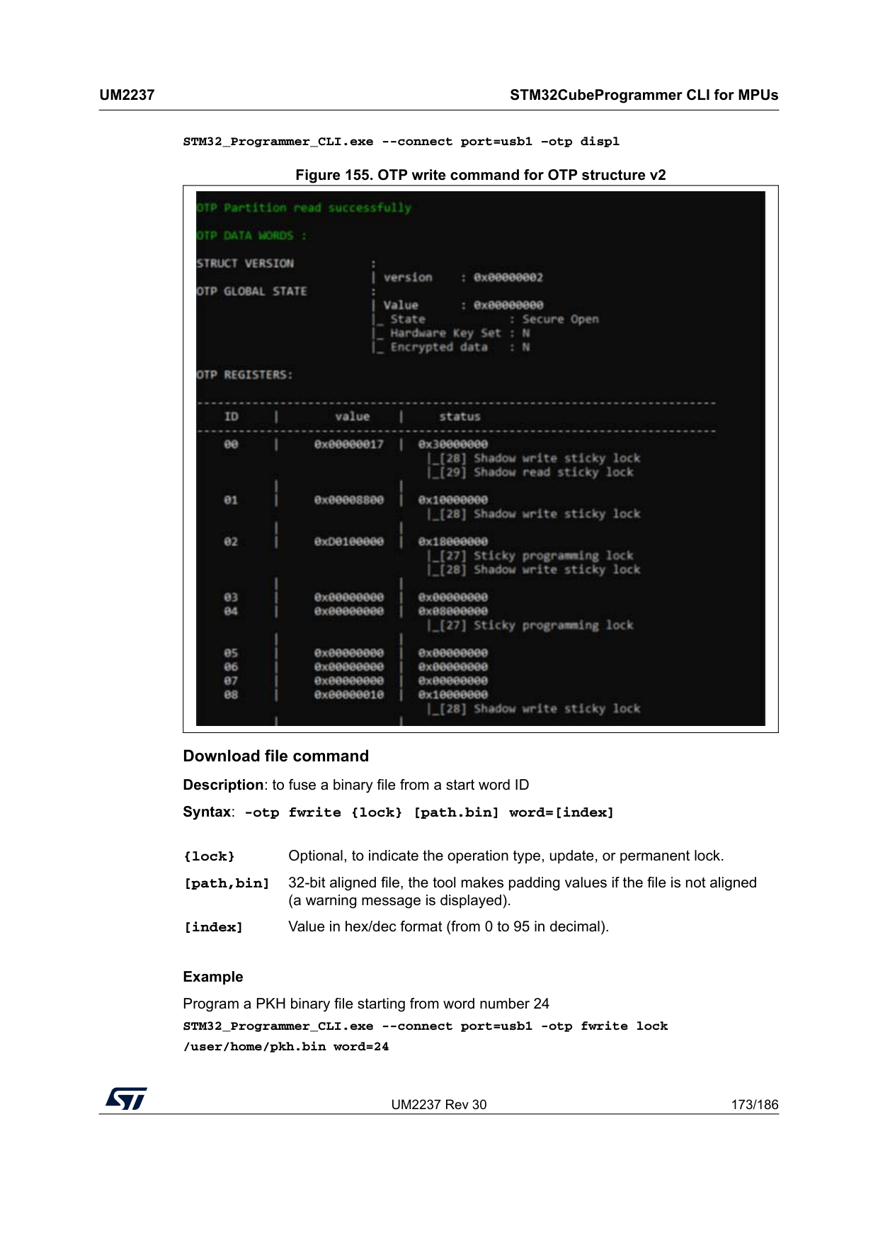
UM2237 Rev 30 173/186
Um2237
STM32CubeProgrammer CLI for MPUs 185 STM32_Programmer_CLI.exe --connect port=usb1 –otp displ Figure 155. OTP write command for OTP structure v2 Download file command Description: to fuse a binary file from a start word ID Syntax: -otp fwrite {lock} [path.bin] word=[index]Example Program a PKH binary file starting from word number 24 STM32_Programmer_CLI.exe --connect port=usb1 -otp fwrite lock /user/home/pkh.bin word=24 {lock} Optional, to indicate the operation type, update, or permanent lock. [path,bin] 32-bit aligned file, the tool makes padding values if the file is not aligned (a warning message is displayed). [index] Value in hex/dec format (from 0 to 95 in decimal).
STM32CubeProgrammer CLI for MPUs
Um2237
174/186 UM2237 Rev 30 OTP File write command: You are trying to program a binary file on OTP partition with the following inputs: ---------------------------------- File name | pkh.bin File size | 32 Bytes Start word ID | 24 Lock | YES ---------------------------------- 5.1.13 Detach command Description: This command allows the user to send detach command to USB DFU. Syntax: -detach 5.1.14 GetCertif command Description: This command can be used to read the chip certificate and save the data to a binary file. The resulting file is required to obtain the associated device product ID, which can then be used to select the appropriate personalization data for the HSM card before using the SSP procedure. Syntax: -gc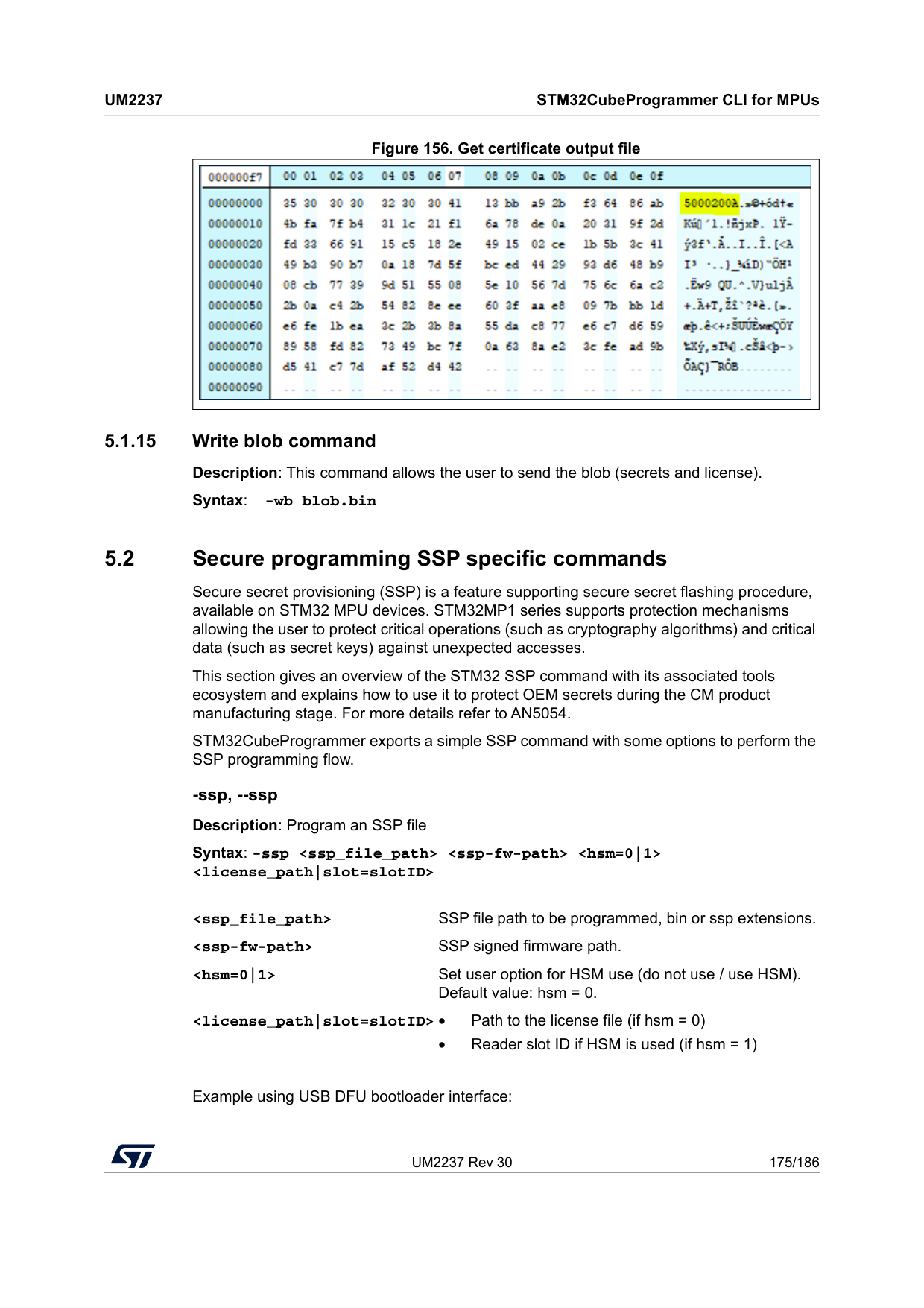
UM2237 Rev 30 175/186
Um2237
STM32CubeProgrammer CLI for MPUs 185 Figure 156. Get certificate output file 5.1.15 Write blob command Description: This command allows the user to send the blob (secrets and license). Syntax: -wb blob.bin 5.2 Secure programming SSP specific commands Secure secret provisioning (SSP) is a feature supporting secure secret flashing procedure, available on STM32 MPU devices. STM32MP1 series supports protection mechanisms allowing the user to protect critical operations (such as cryptography algorithms) and critical data (such as secret keys) against unexpected accesses. This section gives an overview of the STM32 SSP command with its associated tools ecosystem and explains how to use it to protect OEM secrets during the CM product manufacturing stage. For more details refer to AN5054. STM32CubeProgrammer exports a simple SSP command with some options to perform the SSP programming flow. -ssp, --ssp Description: Program an SSP file Syntax: -sspExample using USB DFU bootloader interface:
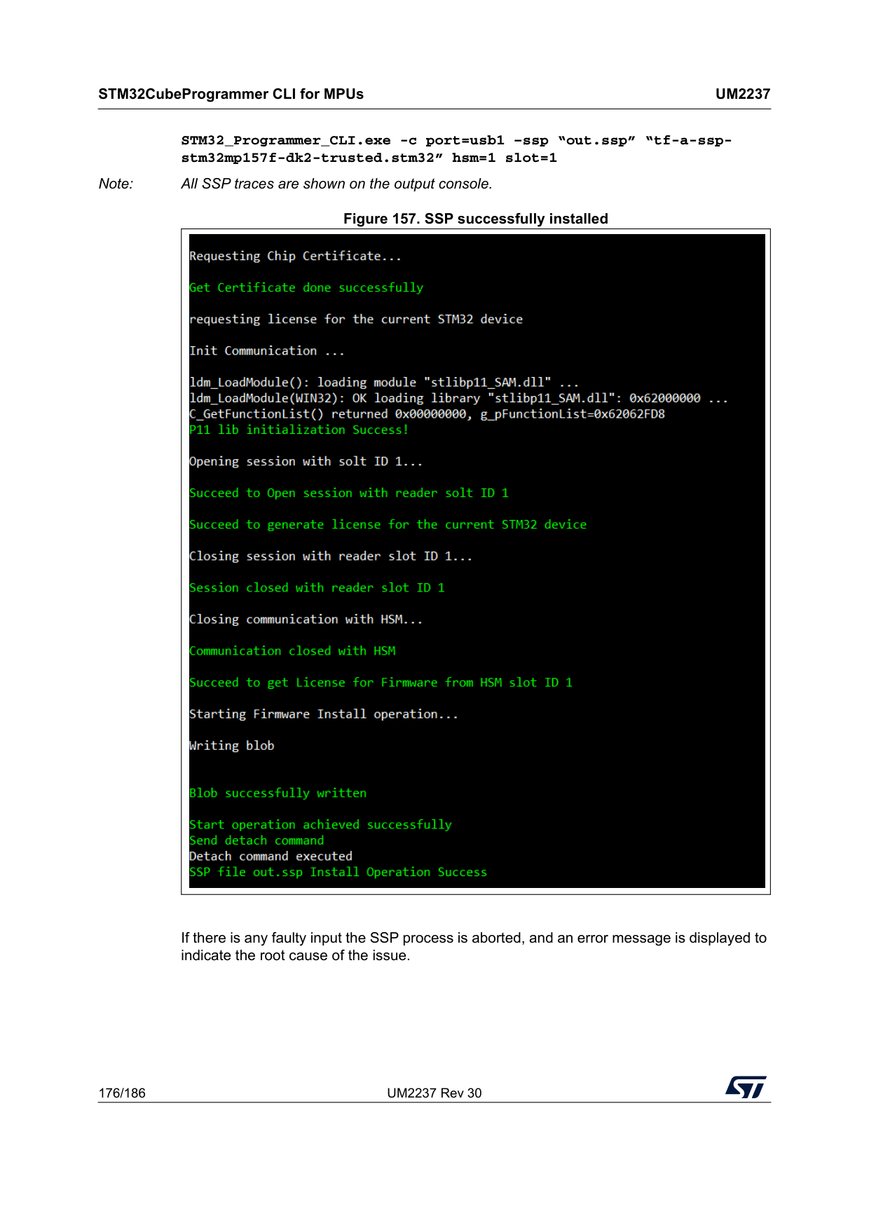
STM32CubeProgrammer CLI for MPUs
Um2237
176/186 UM2237 Rev 30 STM32_Programmer_CLI.exe -c port=usb1 –ssp “out.ssp” “tf-a-ssp- stm32mp157f-dk2-trusted.stm32” hsm=1 slot=1 Note: All SSP traces are shown on the output console. Figure 157. SSP successfully installed If there is any faulty input the SSP process is aborted, and an error message is displayed to indicate the root cause of the issue.
UM2237 Rev 30 177/186
Um2237
STM32CubeProgrammer C++ API 185 6 STM32CubeProgrammer C++ API In addition to the graphical user interface and to the command line interface STM32CubeProgrammer offers a C++ API that can be used to develop your application and benefit of the wide range of features to program the memories embedded in STM32 microcontrollers, either over the debug interface or the bootloader interface (USB DFU, UART, I2C, SPI and CAN). For more information about the C++ API, read the help file provided within the STM32CubeProgrammer package under API\doc folder.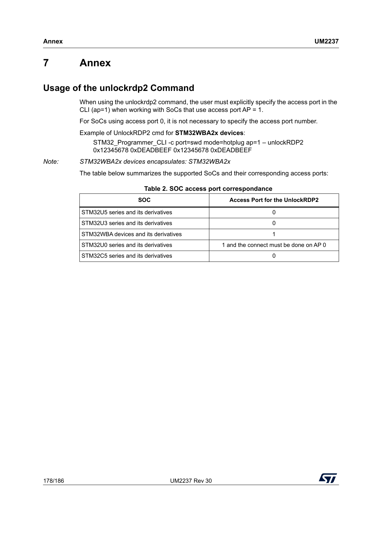
Annex
Um2237
178/186 UM2237 Rev 30 7 Annex Usage of the unlockrdp2 Command When using the unlockrdp2 command, the user must explicitly specify the access port in the CLI (ap=1) when working with SoCs that use access port AP = 1. For SoCs using access port 0, it is not necessary to specify the access port number. Example of UnlockRDP2 cmd for STM32WBA2x devices: STM32_Programmer_CLI -c port=swd mode=hotplug ap=1 – unlockRDP2 0x12345678 0xDEADBEEF 0x12345678 0xDEADBEEF Note: STM32WBA2x devices encapsulates: STM32WBA2x The table below summarizes the supported SoCs and their corresponding access ports:Table 2. SOC access port correspondance
Soc
Access Port for the UnlockRDP2 STM32U5 series and its derivatives 0 STM32U3 series and its derivatives 0 STM32WBA devices and its derivatives 1 STM32U0 series and its derivatives 1 and the connect must be done on AP 0 STM32C5 series and its derivatives 0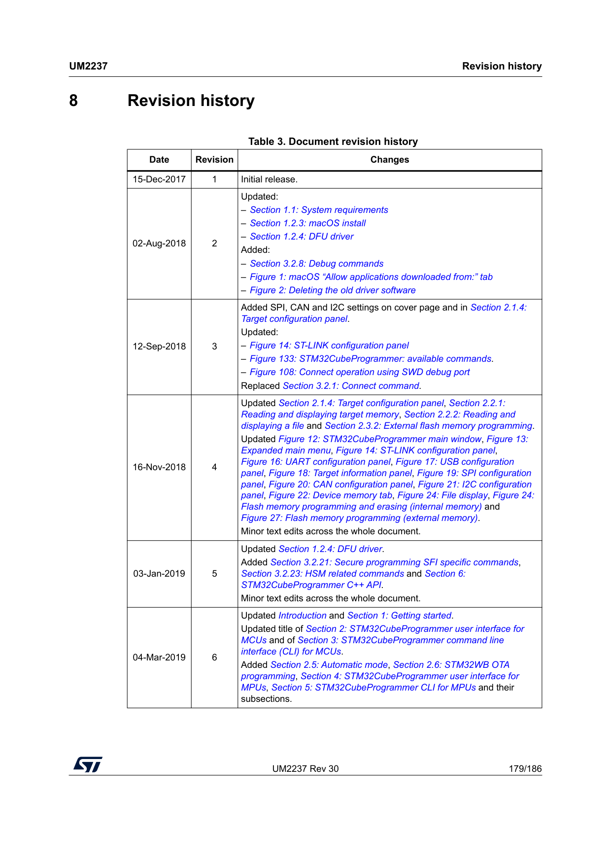
UM2237 Rev 30 179/186
Um2237
Revision history 185 8 Revision historyTable 3. Document revision history Date Revision Changes 15-Dec-2017 1 Initial release. 02-Aug-2018 2 Updated: – Section 1.1: System requirements – Section 1.2.3: macOS install – Section 1.2.4: DFU driver Added: – Section 3.2.8: Debug commands – Figure 1: macOS “Allow applications downloaded from:” tab – Figure 2: Deleting the old driver software 12-Sep-2018 3 Added SPI, CAN and I2C settings on cover page and in Section 2.1.4: Target configuration panel. Updated: – Figure 14: ST-LINK configuration panel – Figure 133: STM32CubeProgrammer: available commands. – Figure 108: Connect operation using SWD debug port Replaced Section 3.2.1: Connect command. 16-Nov-2018 4 Updated Section 2.1.4: Target configuration panel, Section 2.2.1: Reading and displaying target memory, Section 2.2.2: Reading and displaying a file and Section 2.3.2: External flash memory programming. Updated Figure 12: STM32CubeProgrammer main window, Figure 13: Expanded main menu, Figure 14: ST-LINK configuration panel, Figure 16: UART configuration panel, Figure 17: USB configuration panel, Figure 18: Target information panel, Figure 19: SPI configuration panel, Figure 20: CAN configuration panel, Figure 21: I2C configuration panel, Figure 22: Device memory tab, Figure 24: File display, Figure 24: Flash memory programming and erasing (internal memory) and Figure 27: Flash memory programming (external memory). Minor text edits across the whole document. 03-Jan-2019 5 Updated Section 1.2.4: DFU driver. Added Section 3.2.21: Secure programming SFI specific commands, Section 3.2.23: HSM related commands and Section 6: STM32CubeProgrammer C++ API. Minor text edits across the whole document. 04-Mar-2019 6 Updated Introduction and Section 1: Getting started. Updated title of Section 2: STM32CubeProgrammer user interface for MCUs and of Section 3: STM32CubeProgrammer command line interface (CLI) for MCUs. Added Section 2.5: Automatic mode, Section 2.6: STM32WB OTA programming, Section 4: STM32CubeProgrammer user interface for MPUs, Section 5: STM32CubeProgrammer CLI for MPUs and their subsections.
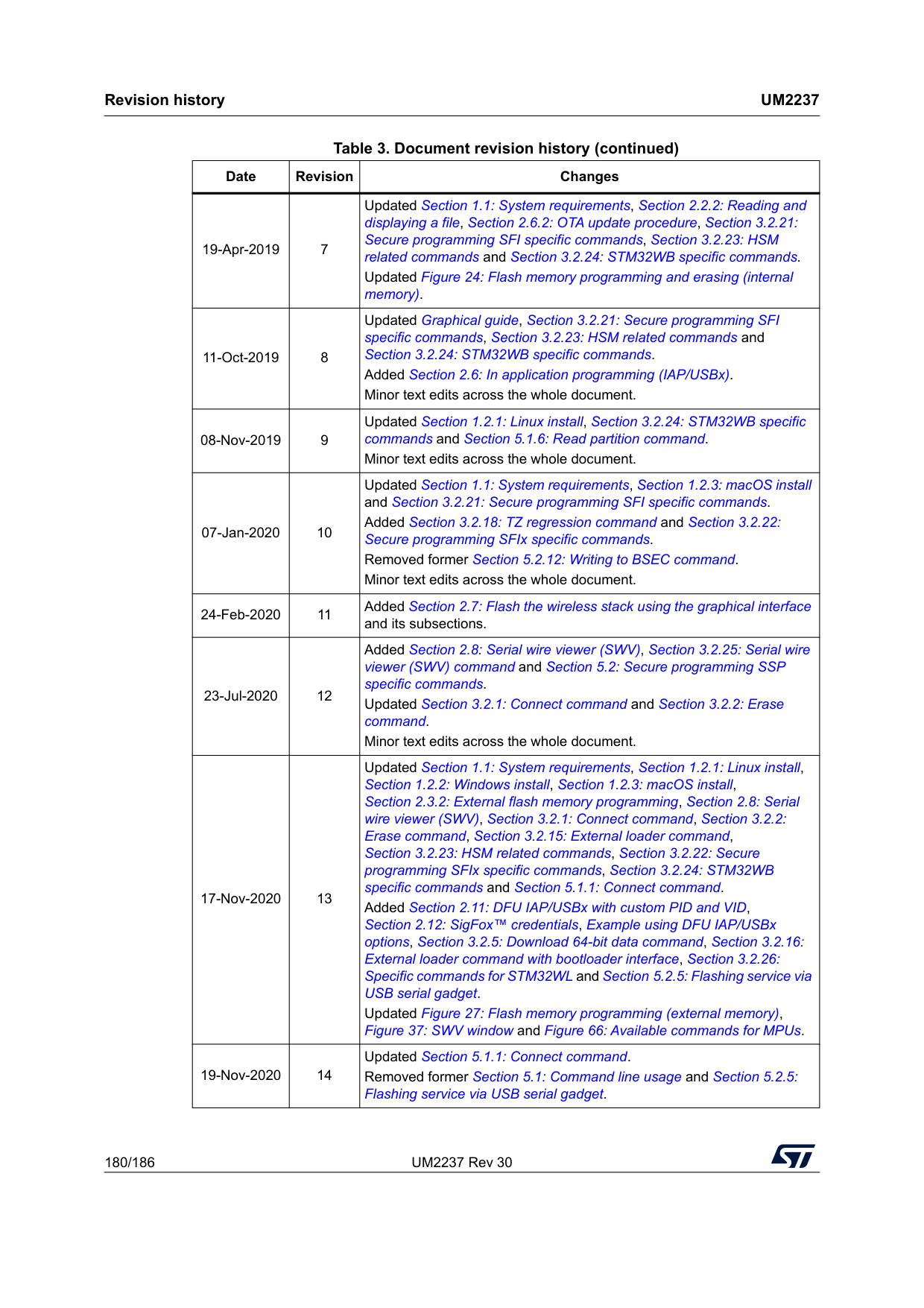
Revision history
Um2237
180/186 UM2237 Rev 30 19-Apr-2019 7 Updated Section 1.1: System requirements, Section 2.2.2: Reading and displaying a file, Section 2.6.2: OTA update procedure, Section 3.2.21: Secure programming SFI specific commands, Section 3.2.23: HSM related commands and Section 3.2.24: STM32WB specific commands. Updated Figure 24: Flash memory programming and erasing (internal memory). 11-Oct-2019 8 Updated Graphical guide, Section 3.2.21: Secure programming SFI specific commands, Section 3.2.23: HSM related commands and Section 3.2.24: STM32WB specific commands. Added Section 2.6: In application programming (IAP/USBx). Minor text edits across the whole document. 08-Nov-2019 9 Updated Section 1.2.1: Linux install, Section 3.2.24: STM32WB specific commands and Section 5.1.6: Read partition command. Minor text edits across the whole document. 07-Jan-2020 10 Updated Section 1.1: System requirements, Section 1.2.3: macOS install and Section 3.2.21: Secure programming SFI specific commands. Added Section 3.2.18: TZ regression command and Section 3.2.22: Secure programming SFIx specific commands. Removed former Section 5.2.12: Writing to BSEC command. Minor text edits across the whole document. 24-Feb-2020 11 Added Section 2.7: Flash the wireless stack using the graphical interface and its subsections. 23-Jul-2020 12 Added Section 2.8: Serial wire viewer (SWV), Section 3.2.25: Serial wire viewer (SWV) command and Section 5.2: Secure programming SSP specific commands. Updated Section 3.2.1: Connect command and Section 3.2.2: Erase command. Minor text edits across the whole document. 17-Nov-2020 13 Updated Section 1.1: System requirements, Section 1.2.1: Linux install, Section 1.2.2: Windows install, Section 1.2.3: macOS install, Section 2.3.2: External flash memory programming, Section 2.8: Serial wire viewer (SWV), Section 3.2.1: Connect command, Section 3.2.2: Erase command, Section 3.2.15: External loader command, Section 3.2.23: HSM related commands, Section 3.2.22: Secure programming SFIx specific commands, Section 3.2.24: STM32WB specific commands and Section 5.1.1: Connect command. Added Section 2.11: DFU IAP/USBx with custom PID and VID, Section 2.12: SigFox™ credentials, Example using DFU IAP/USBx options, Section 3.2.5: Download 64-bit data command, Section 3.2.16: External loader command with bootloader interface, Section 3.2.26: Specific commands for STM32WL and Section 5.2.5: Flashing service via USB serial gadget. Updated Figure 27: Flash memory programming (external memory), Figure 37: SWV window and Figure 66: Available commands for MPUs. 19-Nov-2020 14 Updated Section 5.1.1: Connect command. Removed former Section 5.1: Command line usage and Section 5.2.5: Flashing service via USB serial gadget. Table 3. Document revision history (continued) Date Revision Changes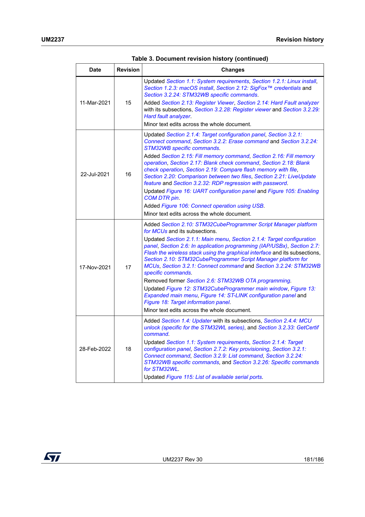
UM2237 Rev 30 181/186
Um2237
Revision history 185 11-Mar-2021 15 Updated Section 1.1: System requirements, Section 1.2.1: Linux install, Section 1.2.3: macOS install, Section 2.12: SigFox™ credentials and Section 3.2.24: STM32WB specific commands. Added Section 2.13: Register Viewer, Section 2.14: Hard Fault analyzer with its subsections, Section 3.2.28: Register viewer and Section 3.2.29: Hard fault analyzer. Minor text edits across the whole document. 22-Jul-2021 16 Updated Section 2.1.4: Target configuration panel, Section 3.2.1: Connect command, Section 3.2.2: Erase command and Section 3.2.24: STM32WB specific commands. Added Section 2.15: Fill memory command, Section 2.16: Fill memory operation, Section 2.17: Blank check command, Section 2.18: Blank check operation, Section 2.19: Compare flash memory with file, Section 2.20: Comparison between two files, Section 2.21: LiveUpdate feature and Section 3.2.32: RDP regression with password. Updated Figure 16: UART configuration panel and Figure 105: Enabling COM DTR pin. Added Figure 106: Connect operation using USB. Minor text edits across the whole document. 17-Nov-2021 17 Added Section 2.10: STM32CubeProgrammer Script Manager platform for MCUs and its subsections. Updated Section 2.1.1: Main menu, Section 2.1.4: Target configuration panel, Section 2.6: In application programming (IAP/USBx), Section 2.7: Flash the wireless stack using the graphical interface and its subsections, Section 2.10: STM32CubeProgrammer Script Manager platform for MCUs, Section 3.2.1: Connect command and Section 3.2.24: STM32WB specific commands. Removed former Section 2.6: STM32WB OTA programming. Updated Figure 12: STM32CubeProgrammer main window, Figure 13: Expanded main menu, Figure 14: ST-LINK configuration panel and Figure 18: Target information panel. Minor text edits across the whole document. 28-Feb-2022 18 Added Section 1.4: Updater with its subsections, Section 2.4.4: MCU unlock (specific for the STM32WL series), and Section 3.2.33: GetCertif command. Updated Section 1.1: System requirements, Section 2.1.4: Target configuration panel, Section 2.7.2: Key provisioning, Section 3.2.1: Connect command, Section 3.2.9: List command, Section 3.2.24: STM32WB specific commands, and Section 3.2.26: Specific commands for STM32WL. Updated Figure 115: List of available serial ports. Table 3. Document revision history (continued) Date Revision Changes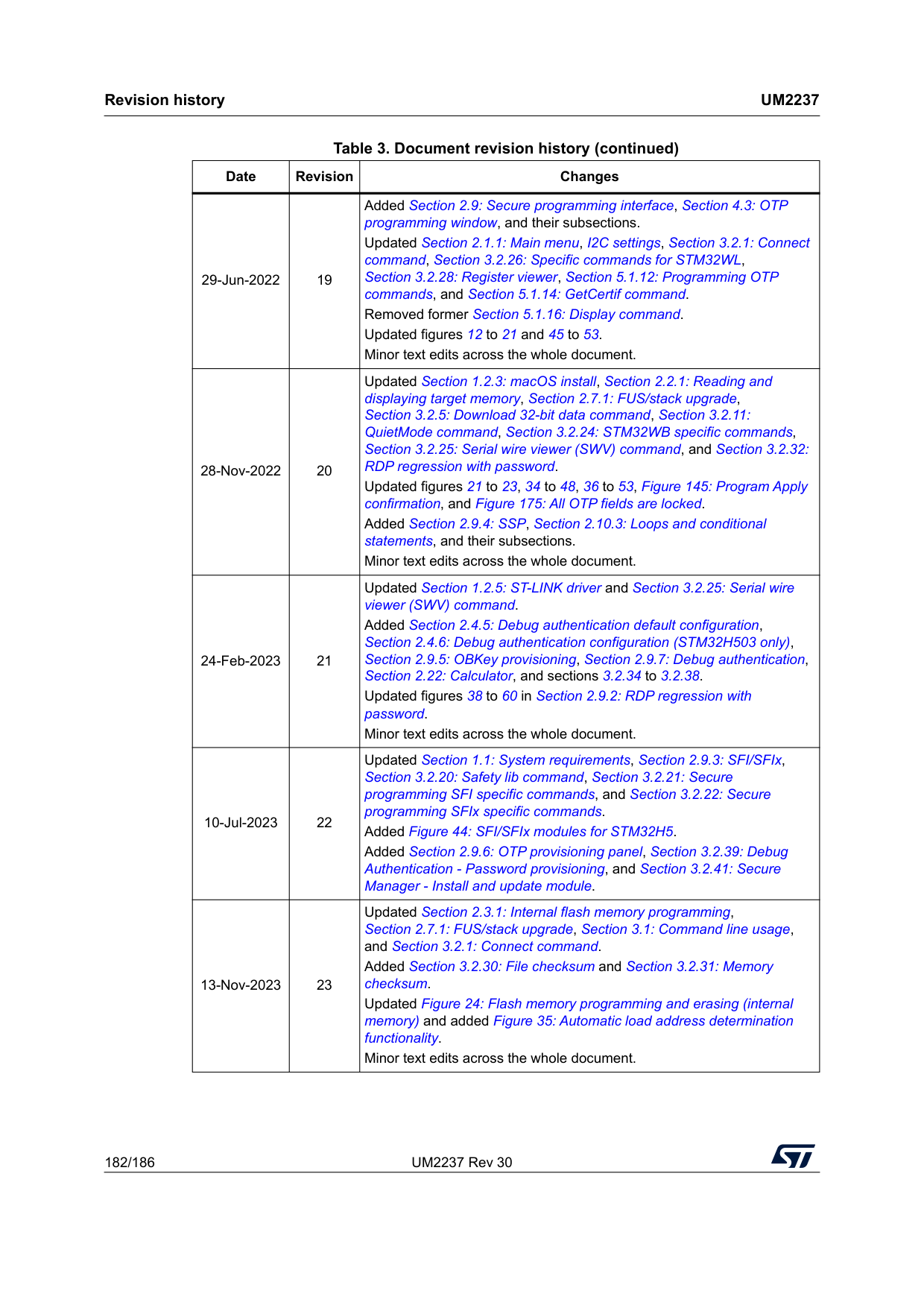
Revision history
Um2237
182/186 UM2237 Rev 30 29-Jun-2022 19 Added Section 2.9: Secure programming interface, Section 4.3: OTP programming window, and their subsections. Updated Section 2.1.1: Main menu, I2C settings, Section 3.2.1: Connect command, Section 3.2.26: Specific commands for STM32WL, Section 3.2.28: Register viewer, Section 5.1.12: Programming OTP commands, and Section 5.1.14: GetCertif command. Removed former Section 5.1.16: Display command. Updated figures 12 to 21 and 45 to 53. Minor text edits across the whole document. 28-Nov-2022 20 Updated Section 1.2.3: macOS install, Section 2.2.1: Reading and displaying target memory, Section 2.7.1: FUS/stack upgrade, Section 3.2.5: Download 32-bit data command, Section 3.2.11: QuietMode command, Section 3.2.24: STM32WB specific commands, Section 3.2.25: Serial wire viewer (SWV) command, and Section 3.2.32: RDP regression with password. Updated figures 21 to 23, 34 to 48, 36 to 53, Figure 145: Program Apply confirmation, and Figure 175: All OTP fields are locked. Added Section 2.9.4: SSP, Section 2.10.3: Loops and conditional statements, and their subsections. Minor text edits across the whole document. 24-Feb-2023 21 Updated Section 1.2.5: ST-LINK driver and Section 3.2.25: Serial wire viewer (SWV) command. Added Section 2.4.5: Debug authentication default configuration, Section 2.4.6: Debug authentication configuration (STM32H503 only), Section 2.9.5: OBKey provisioning, Section 2.9.7: Debug authentication, Section 2.22: Calculator, and sections 3.2.34 to 3.2.38. Updated figures 38 to 60 in Section 2.9.2: RDP regression with password. Minor text edits across the whole document. 10-Jul-2023 22 Updated Section 1.1: System requirements, Section 2.9.3: SFI/SFIx, Section 3.2.20: Safety lib command, Section 3.2.21: Secure programming SFI specific commands, and Section 3.2.22: Secure programming SFIx specific commands. Added Figure 44: SFI/SFIx modules for STM32H5. Added Section 2.9.6: OTP provisioning panel, Section 3.2.39: Debug Authentication - Password provisioning, and Section 3.2.41: Secure Manager - Install and update module. 13-Nov-2023 23 Updated Section 2.3.1: Internal flash memory programming, Section 2.7.1: FUS/stack upgrade, Section 3.1: Command line usage, and Section 3.2.1: Connect command. Added Section 3.2.30: File checksum and Section 3.2.31: Memory checksum. Updated Figure 24: Flash memory programming and erasing (internal memory) and added Figure 35: Automatic load address determination functionality. Minor text edits across the whole document. Table 3. Document revision history (continued) Date Revision Changes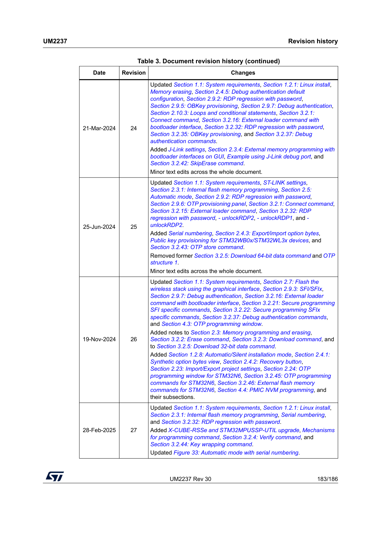
UM2237 Rev 30 183/186
Um2237
Revision history 185 21-Mar-2024 24 Updated Section 1.1: System requirements, Section 1.2.1: Linux install, Memory erasing, Section 2.4.5: Debug authentication default configuration, Section 2.9.2: RDP regression with password, Section 2.9.5: OBKey provisioning, Section 2.9.7: Debug authentication, Section 2.10.3: Loops and conditional statements, Section 3.2.1: Connect command, Section 3.2.16: External loader command with bootloader interface, Section 3.2.32: RDP regression with password, Section 3.2.35: OBKey provisioning, and Section 3.2.37: Debug authentication commands. Added J-Link settings, Section 2.3.4: External memory programming with bootloader interfaces on GUI, Example using J-Link debug port, and Section 3.2.42: SkipErase command. Minor text edits across the whole document. 25-Jun-2024 25 Updated Section 1.1: System requirements, ST-LINK settings, Section 2.3.1: Internal flash memory programming, Section 2.5: Automatic mode, Section 2.9.2: RDP regression with password, Section 2.9.6: OTP provisioning panel, Section 3.2.1: Connect command, Section 3.2.15: External loader command, Section 3.2.32: RDP regression with password, - unlockRDP2, - unlockRDP1, and - unlockRDP2. Added Serial numbering, Section 2.4.3: Export/import option bytes, Public key provisioning for STM32WB0x/STM32WL3x devices, and Section 3.2.43: OTP store command. Removed former Section 3.2.5: Download 64-bit data command and OTP structure 1. Minor text edits across the whole document. 19-Nov-2024 26 Updated Section 1.1: System requirements, Section 2.7: Flash the wireless stack using the graphical interface, Section 2.9.3: SFI/SFIx, Section 2.9.7: Debug authentication, Section 3.2.16: External loader command with bootloader interface, Section 3.2.21: Secure programming SFI specific commands, Section 3.2.22: Secure programming SFIx specific commands, Section 3.2.37: Debug authentication commands, and Section 4.3: OTP programming window. Added notes to Section 2.3: Memory programming and erasing, Section 3.2.2: Erase command, Section 3.2.3: Download command, and to Section 3.2.5: Download 32-bit data command. Added Section 1.2.8: Automatic/Silent installation mode, Section 2.4.1: Synthetic option bytes view, Section 2.4.2: Recovery button, Section 2.23: Import/Export project settings, Section 2.24: OTP programming window for STM32N6, Section 3.2.45: OTP programming commands for STM32N6, Section 3.2.46: External flash memory commands for STM32N6, Section 4.4: PMIC NVM programming, and their subsections. 28-Feb-2025 27 Updated Section 1.1: System requirements, Section 1.2.1: Linux install, Section 2.3.1: Internal flash memory programming, Serial numbering, and Section 3.2.32: RDP regression with password. Added X-CUBE-RSSe and STM32MPUSSP-UTIL upgrade, Mechanisms for programming command, Section 3.2.4: Verify command, and Section 3.2.44: Key wrapping command. Updated Figure 33: Automatic mode with serial numbering. Table 3. Document revision history (continued) Date Revision Changes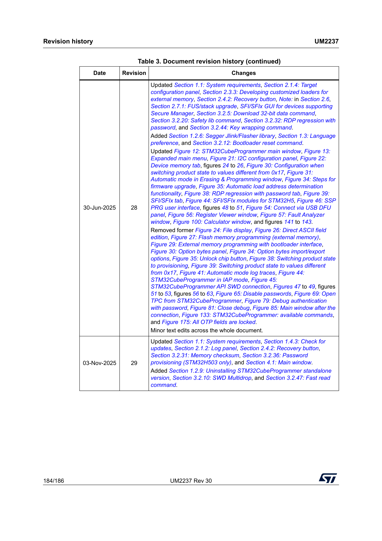
Revision history
Um2237
184/186 UM2237 Rev 30 30-Jun-2025 28 Updated Section 1.1: System requirements, Section 2.1.4: Target configuration panel, Section 2.3.3: Developing customized loaders for external memory, Section 2.4.2: Recovery button, Note: in Section 2.6, Section 2.7.1: FUS/stack upgrade, SFI/SFIx GUI for devices supporting Secure Manager, Section 3.2.5: Download 32-bit data command, Section 3.2.20: Safety lib command, Section 3.2.32: RDP regression with password, and Section 3.2.44: Key wrapping command. Added Section 1.2.6: Segger Jlink/Flasher library, Section 1.3: Language preference, and Section 3.2.12: Bootloader reset command. Updated Figure 12: STM32CubeProgrammer main window, Figure 13: Expanded main menu, Figure 21: I2C configuration panel, Figure 22: Device memory tab, figures 24 to 26, Figure 30: Configuration when switching product state to values different from 0x17, Figure 31: Automatic mode in Erasing & Programming window, Figure 34: Steps for firmware upgrade, Figure 35: Automatic load address determination functionality, Figure 38: RDP regression with password tab, Figure 39: SFI/SFIx tab, Figure 44: SFI/SFIx modules for STM32H5, Figure 46: SSP PRG user interface, figures 48 to 51, Figure 54: Connect via USB DFU panel, Figure 56: Register Viewer window, Figure 57: Fault Analyzer window, Figure 100: Calculator window, and figures 141 to 143. Removed former Figure 24: File display, Figure 26: Direct ASCII field edition, Figure 27: Flash memory programming (external memory), Figure 29: External memory programming with bootloader interface, Figure 30: Option bytes panel, Figure 34: Option bytes import/export options, Figure 35: Unlock chip button, Figure 38: Switching product state to provisioning, Figure 39: Switching product state to values different from 0x17, Figure 41: Automatic mode log traces, Figure 44: STM32CubeProgrammer in IAP mode, Figure 45: STM32CubeProgrammer API SWD connection, Figures 47 to 49, figures 51 to 53, figures 56 to 63, Figure 65: Disable passwords, Figure 69: Open TPC from STM32CubeProgrammer, Figure 79: Debug authentication with password, Figure 81: Close debug, Figure 85: Main window after the connection, Figure 133: STM32CubeProgrammer: available commands, and Figure 175: All OTP fields are locked. Minor text edits across the whole document. 03-Nov-2025 29 Updated Section 1.1: System requirements, Section 1.4.3: Check for updates, Section 2.1.2: Log panel, Section 2.4.2: Recovery button, Section 3.2.31: Memory checksum, Section 3.2.36: Password provisioning (STM32H503 only), and Section 4.1: Main window. Added Section 1.2.9: Uninstalling STM32CubeProgrammer standalone version, Section 3.2.10: SWD Multidrop, and Section 3.2.47: Fast read command. Table 3. Document revision history (continued) Date Revision Changes
UM2237 Rev 30 185/186
Um2237
Revision history 185 26-Feb-2026 30 Added: • Section 2.26: STM32V8 NVM programming constraints • Section 2.27: Export MCU memory map • Section 3.2.48: STM32V8 NVM programming constraints • Section 7: Annex Updated: • Section 1: Getting started • Section 1.1: System requirements • Section 2.4.2: Recovery button • Section 2.8: Serial wire viewer (SWV) • Section 2.9.1: Introduction • Section 2.9.2: RDP regression with password • Section 3.1: Command line usage • Section 3.2.32: RDP regression with password Table 3. Document revision history (continued) Date Revision Changes