
Ask AI
— answers from the official manualAnswers from the official manual.
Common questions
Common Questions
10 totalWhat are the safety precautions for using the Velux KFX 210 control system?
The control system must be installed and used by persons aged 8 years and above with sufficient experience and knowledge. Cleaning and user maintenance should not be carried out unsupervised by children, who also must not play with it.
How do I test the Velux KFX 210 after installation or service work?
The control system must be tested after installation, service work, and alterations to ensure compliance with national regulations. It should also undergo an inspection by qualified personnel at least once a year.
What happens if there is a fire alarm while the backup batteries in Velux KFX 210 are being used?
If power fails, back-up batteries ensure emergency power supply for 72 hours. Any alarms will activate during this period when connected windows open automatically.
How do I install smoke detectors with the KFX 210 control system?
Smoke detectors like model KFA 100 should be installed on ceilings according to national legislation and snapped into place after fitting the base. Each control unit can connect up to ten detector units.
What steps are needed for maintenance of Velux KFX 210?
Maintenance includes checking battery status yearly, replacing batteries at least every four years, and inspecting connected products according to their instructions during the yearly inspection.
What are maximum cable lengths for motor terminals of Velux KFX 210?
For connection of smoke ventilation windows GGL/GGU-K-- ----40, the table on page 15 provides specific maximum lengths and prescribed cross-sectional sizes of cables depending on conductor count.
Full Manual
32 pages
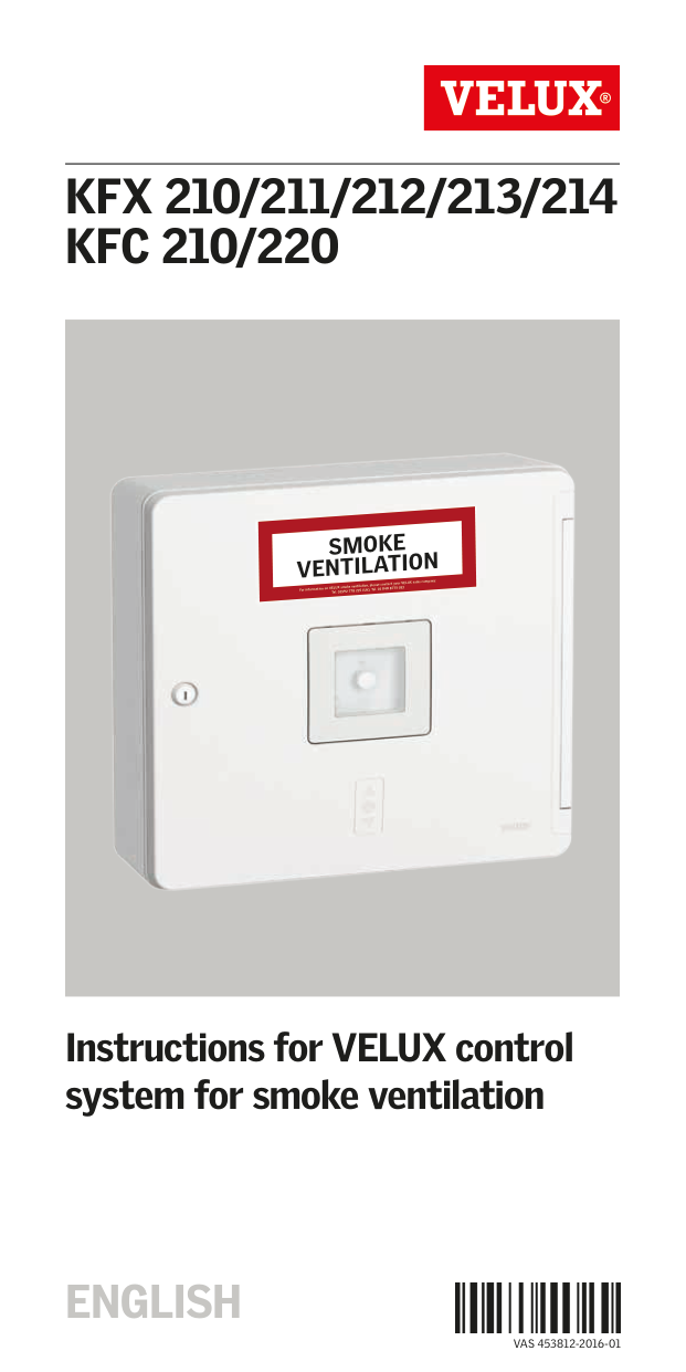
KFX 210/211/212/213/214 KFC 210/220

SMOKE VENTILATION
For information on VELUX smoke ventilation, please contact your VELUX sales company: Tel. 01592 778 225 (UK), Tel. 01 848 8775 (IE)
Instructions for VELUX control system for smoke ventilation
ENGLISH

VAS 453812-2016-01
######## Contents
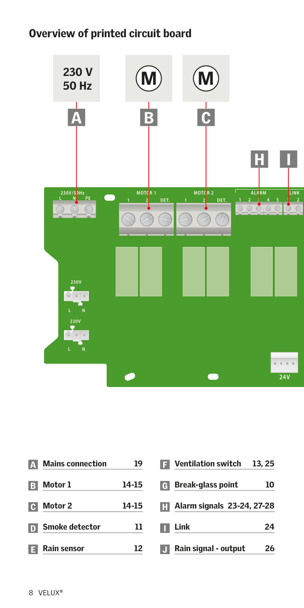
Important information 4-5 Contents of packaging 6-7 Overview of printed circuit board 8-9 Break-glass point KFK 100 10 Smoke detector KFA 100 11 Rain sensor KLA 200 12 Ventilation switch KFK 200 13 Motor terminals 14 Wiring 15 Setting of switches 16 Operation of and signals from control unit 17 Back-up batteries 18 Mains connection 19 Status and error indication in control system 20-22 Connected control units 23-28
Replacement of frame in control unit 30 Technical data 31
Please read instructions carefully before proceeding and keep them for future reference behind the battery holder inside the control unit.
########### Safety
########### Product
########### Maintenance and service

########### Declaration of Conformity According to the Council Directive 2014/35/EU We herewith declare that the VELUX control systems for smoke ventilation
KFX 211 (control unit 3FC F21, smoke detector KFA 100/3FA F01 and
KFX 212 (control unit 3FC F21, smoke detector KFA 100/3FA F01 and
KFX 213 (control unit 3FC F21, smoke detector KFA 100/3FA F01 and
KFX 214 (control unit 3FC F21, smoke detector KFA 100/3FA F01 and
2014/35/EU and EMC Directive 2014/30/EU 1and
− have been manufactured in accordance with the harmonised standards EN 61000-3-2(2006)+A1(2009)+A2(2009), EN 61000-3-3(2008), EN 55014-1(2006)+A1(2009)+A2(2011), EN 50130-4(2011), EN 60335-1 and EN 62233.
When one of the above-mentioned VELUX control systems or VELUX control units are connected to a VELUX smoke ventilation window GGL -K-- ----40, GGU -K-- ----40 or CSP, the total system is to be considered as a machine, which is not to be put into service until it has been installed according to instructions and requirements. The total system then complies with the essential requirements of the Council Directives 2014/35/EU, 2014/30/EU and 2006/42/EC.
The control systems and control units also comply with the Construction Products Regulation (EU) No. 305/2011. For Declaration of Performance, please go to www.velux.com.

VELUX A/S: . . . . . . . . . . . . . . . . . . . . . . . . . . . . . . . . . . . . . . . . . . . . . . . . . . . . . . . . . . . (Jens Aksel Thomsen, Test Engineer, Market Approval)
15-02-2015
Ådalsvej 99, DK-2970 Hørsholm. . . . . . . . . . . . . . . . . . . . . . . . . . . . . . . . . . . . . . . . . . CE DoC 940402-01
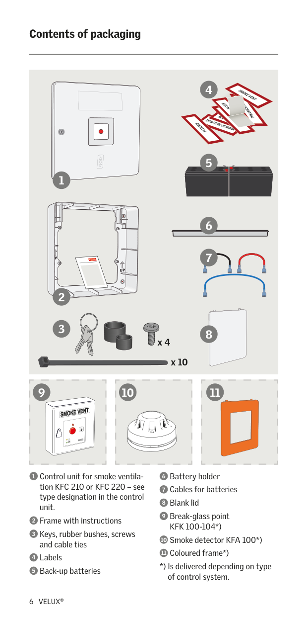
######## Contents of packaging
SMOKE VENT
ABV-CENTRAL
ESCAP
ROO
EXTRACTOR DE HUMOR
RØGLEM
1
2
3
x 4
x 10
9 10 11
*) Is delivered depending on type of control system.
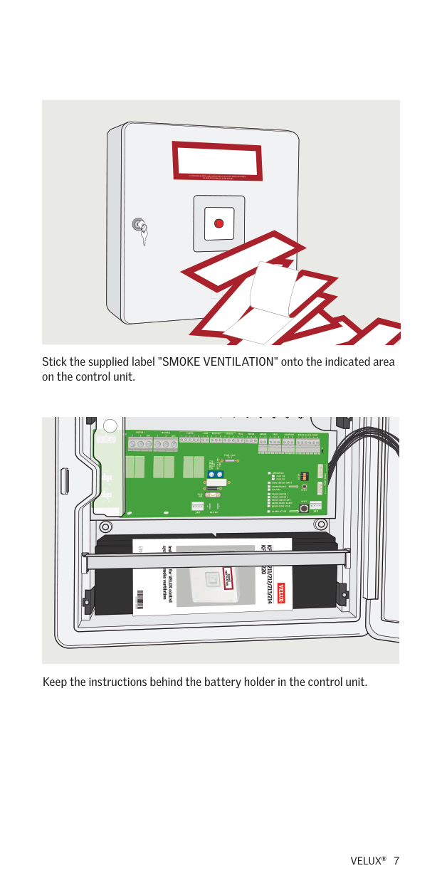
Stick the supplied label "SMOKE VENTILATION" onto the indicated area on the control unit.
| | | |---|---| | | |


Keep the instructions behind the battery holder in the control unit.
######## Overview of printed circuit board
M M230 V50 Hz BA C
##### H I
ALARMMOTOR 2MOTOR 1230V/50Hz
LINK DET.21DET.21
PENL
2132541
230V
| | | | | | | |---|---|---|---|---|---| | | | | | | | | | | | | | |
NL
230V
| | | | | | | |---|---|---|---|---|---| | | | | | | | | | | | | | |
NL
| | |---|
| | |---|
| | |---|
| | |---|
| | |---|
| | |---|
| | |---| | |
24V
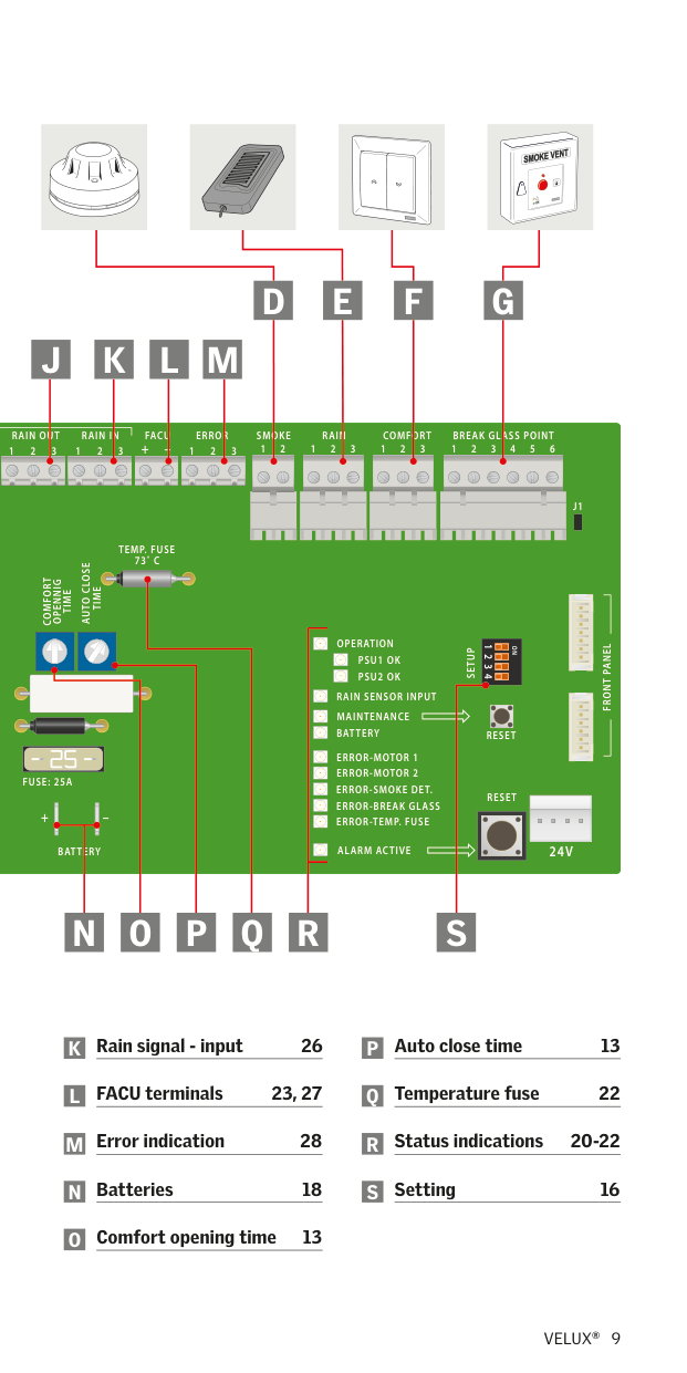
##### D E F G J K L M
BREAK GLASS POINTRAINRAIN INCOMFORTSMOKERAIN OUTERROR
FACU
65432132132121132+–213213
J1
TEMP. FUSE
73˚ C
TIME AUTO CLOSE
COMFORT
TIME OPENNIG
| | | |---|---| | | | |–|–|
OPERATION
FRONT PANEL
| | | |---|---|
1
ON 234
SETUP
PSU1 OK
| | | |---|---|
| | | |---|---|
PSU2 OK
| | | |---|---|
RAIN SENSOR INPUT
MAINTENANCE BATTERY
RESET
FUSE: 25A
RESET
| | |---| | |
| | | |---|---| |BATT|R|
+
ERROR-TEMP. FUSE
24V
ALARM ACTIVE
##### P QO R SN
######## Break-glass point KFK 100
LINK FACU 2121PENL
BREAK GLASS POINTRAINRAIN INCOMFORTSMOKERAIN OUTERRORALARMMOTOR 2MOTOR 1230V/50Hz
65432132132121132+–2132132132541
TEMP. FUSE
73˚ C
| | | |---|---| | | |
TIME AUTO CLOSE
COMFORT
TIME OPENNIG
230V
OPERATION
FRONT PANEL
SETUP
PSU2 OK
RAIN SENSOR INPUT MAINTENANCE BATTERY
NL
230V
RESET
NL
+ – 24V 24V
BATTERY
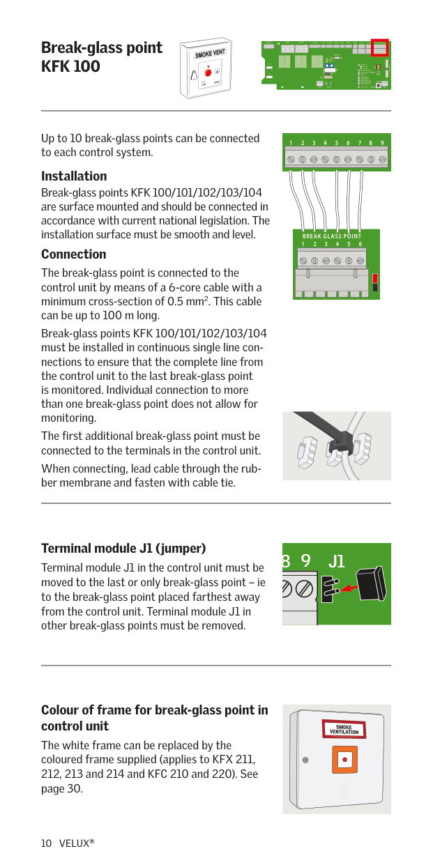
Up to 10 break-glass points can be connected to each control system.
6 7 8 954321
| | |---| | | | |
Installation Break-glass points KFK 100/101/102/103/104 are surface mounted and should be connected in accordance with current national legislation. The installation surface must be smooth and level. Connection The break-glass point is connected to the control unit by means of a 6-core cable with a minimum cross-section of 0.5 mm2. This cable can be up to 100 m long. Break-glass points KFK 100/101/102/103/104 must be installed in continuous single line connections to ensure that the complete line from the control unit to the last break-glass point is monitored. Individual connection to more than one break-glass point does not allow for monitoring. The first additional break-glass point must be connected to the terminals in the control unit. When connecting, lead cable through the rubber membrane and fasten with cable tie.
FACU BREAK GLASS POINTRAINRAIN INSMOKERAIN OUTERROR
654321+
| | | | | | | | | |---|---|---|---|---|---|---|---|
| | | | | | | | | | | | | | | | | |
| | | | | | | | | |---|---|---|---|---|---|---|---| | | | | | | | | | | | | | | | | | |
| | | | | | | | | | | | | | | | |---|---|---|---|---|---|---|---|---|---|---|---|---|---|---| | | | | | | | | | | | | | | | | | | | | | | | | | | | | | | | | | | | | | | | | | | | | | | | |
J1
Terminal module J1 (jumper) Terminal module J1 in the control unit must be moved to the last or only break-glass point – ie to the break-glass point placed farthest away from the control unit. Terminal module J1 in other break-glass points must be removed.
8 9 J1
########## Colour of frame for break-glass point in control unit
The white frame can be replaced by the coloured frame supplied (applies to KFX 211, 212, 213 and 214 and KFC 210 and 220). See page 30.
######## Smoke detector KFA 100
LINK FACU 2121PENL
BREAK GLASS POINTRAINRAIN INCOMFORTSMOKERAIN OUTERRORALARMMOTOR 2MOTOR 1230V/50Hz
65432132132121132+–2132132132541
TEMP. FUSE
73˚ C
| | | |---|---| | | |
TIME AUTO CLOSE
COMFORT
TIME OPENNIG
230V
OPERATION
FRONT PANEL
SETUP
PSU2 OK
RAIN SENSOR INPUT MAINTENANCE BATTERY
NL
230V
RESET
NL
RESET
+ – 24V 24V
BATTERY
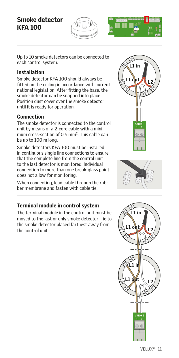
Up to 10 smoke detectors can be connected to each control system.
L1 in
Installation Smoke detector KFA 100 should always be fitted on the ceiling in accordance with current national legislation. After fitting the base, the smoke detector can be snapped into place. Position dust cover over the smoke detector until it is ready for operation.
L1 out
L2
Connection The smoke detector is connected to the control unit by means of a 2-core cable with a minimum cross-section of 0.5 mm2. This cable can be up to 100 m long.
RAIN IN SMOKERAIN OUTALARMMOTOR 2
21+213213213241 LINK FACU DET.2
| | | | | | | |---|---|---|---|---|---| | | | | | | | | | | | | | | | | | | | | |
| | | | | | | | | |---|---|---|---|---|---|---|---| | | | | | | | | | | | | | | | | | |
| | | | | | | | | |---|---|---|---|---|---|---|---| | | | | | | | | | | | | | | | | | |
Smoke detectors KFA 100 must be installed in continuous single line connections to ensure that the complete line from the control unit to the last detector is monitored. Individual connection to more than one break-glass point does not allow for monitoring.
When connecting, lead cable through the rubber membrane and fasten with cable tie.
Terminal module in control system The terminal module in the control unit must be moved to the last or only smoke detector – ie to the smoke detector placed farthest away from the control unit.
L1 in
L1 out
L2
L1 in
L1 out
L2
SMOKE
21
| | | | | | | |---|---|---|---|---|---| | | | | | | | | | | | | | | | | | | | | |
| | | | | | | | | |---|---|---|---|---|---|---|---| | | | | | | | | | | | | | | | | | |
| | | | | | | | | |---|---|---|---|---|---|---|---| | | | | | | | | | | | | | | | | | |
######## Rain sensor KLA 200
LINK FACU 2121PENL
BREAK GLASS POINTRAINRAIN INCOMFORTSMOKERAIN OUTERRORALARMMOTOR 2MOTOR 1230V/50Hz
65432132132121132+–2132132132541
J1
TEMP. FUSE
73˚ C
| | | |---|---| | | |
TIME AUTO CLOSE
COMFORT
TIME OPENNIG
230V
OPERATION
FRONT PANEL
PSU1 OK
PSU2 OK
RAIN SENSOR INPUT
NL
MAINTENANCE BATTERY
230V
RESET
FUSE: 25A
NL
RESET
+ – 24V 24V
ERROR-TEMP. FUSE
ALARM ACTIVE
BATTERY
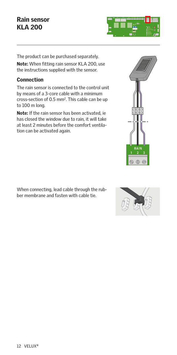
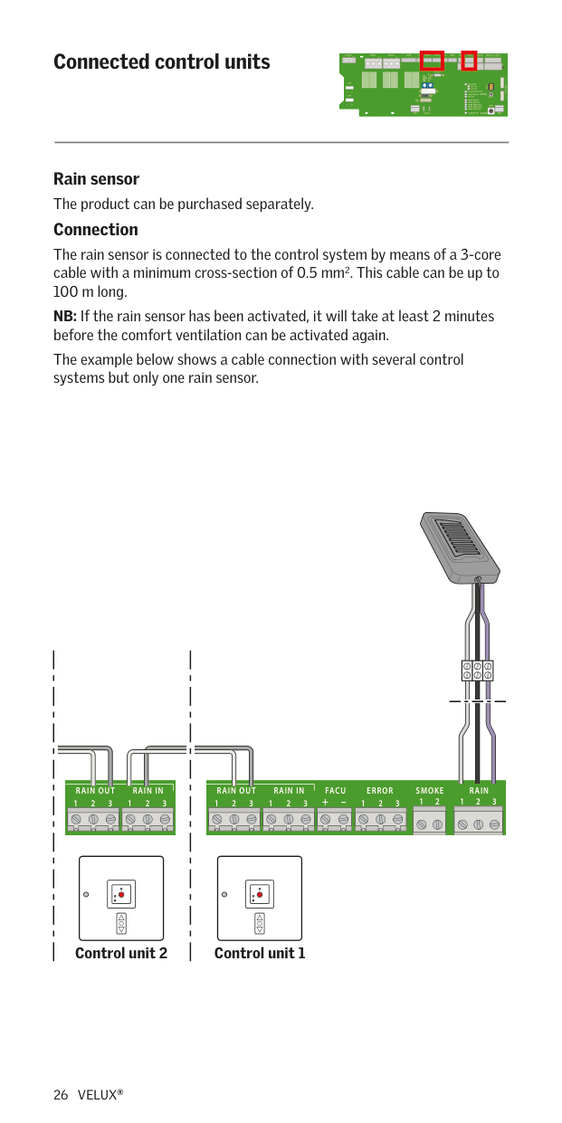
The product can be purchased separately. Note: When fitting rain sensor KLA 200, use the instructions supplied with the sensor. Connection
| | | |---|---| | | |
The rain sensor is connected to the control unit by means of a 3-core cable with a minimum cross-section of 0.5 mm2. This cable can be up to 100 m long.
Note: If the rain sensor has been activated, ie has closed the window due to rain, it will take at least 2 minutes before the comfort ventilation can be activated again.
RAIN
321
| | | | | | | | | |---|---|---|---|---|---|---|---| | | | | | | | | | | | | | | | | | | | | | | | | | | |
| | | | | | | | | |---|---|---|---|---|---|---|---| | | | | | | | | | | | | | | | | | |
| | | | | | | | | | | | | | | | |---|---|---|---|---|---|---|---|---|---|---|---|---|---|---| | | | | | | | | | | | | | | | | | | | | | | | | | | | | | | | |
When connecting, lead cable through the rubber membrane and fasten with cable tie.
######## Ventilation switch KFK 200
LINK FACU 2121PENL
BREAK GLASS POINTRAINRAIN INCOMFORTSMOKERAIN OUTERRORALARMMOTOR 2MOTOR 1230V/50Hz
65432132132121132+–2132132132541
TEMP. FUSE
73˚ C
TIME AUTO CLOSE
COMFORT
TIME OPENNIG
230V
OPERATION
FRONT PANEL
SETUP
PSU2 OK
RAIN SENSOR INPUT
NL
230V
BATTERY
RESET
ERROR-MOTOR 2 ERROR-SMOKE DET. ERROR-BREAK GLASS
NL
+ – 24V 24V
BATTERY
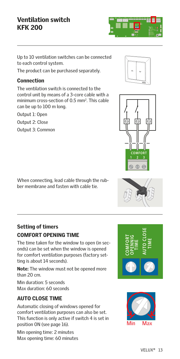
Up to 10 ventilation switches can be connected to each control system. The product can be purchased separately. Connection
The ventilation switch is connected to the control unit by means of a 3-core cable with a minimum cross-section of 0.5 mm2. This cable can be up to 100 m long.
###### RAIN OUT
2 3
COMFORT
321
RAIN OUT
1213232541DET.2
When connecting, lead cable through the rubber membrane and fasten with cable tie.
TEMP. FUSE
TEMP. FUSE
########## Setting of timers COMFORT OPENING TIME
TIME AUTO CLOSE
COMFORT
TIME OPENNIG
TIME AUTO CLOSE
The time taken for the window to open (in seconds) can be set when the window is opened for comfort ventilation purposes (factory setting is about 14 seconds). Note: The window must not be opened more than 20 cm. Min duration: 5 seconds Max duration: 60 seconds AUTO CLOSE TIME Automatic closing of windows opened for comfort ventilation purposes can also be set. This function is only active if switch 4 is set in position ON (see page 16). Min opening time: 2 minutes Max opening time: 60 minutes
COMFORT
TIME OPENNIG
FUSE: 25A
Min Max
######## Motor terminals
LINK FACU 2121PENL
BREAK GLASS POINTRAINRAIN INCOMFORTSMOKERAIN OUTERRORALARMMOTOR 2MOTOR 1230V/50Hz
65432132132121132+–2132132132541
J1
TEMP. FUSE
73˚ C
TIME AUTO CLOSE
COMFORT
TIME OPENNIG
230V
OPERATION
FRONT PANEL
PSU1 OK
PSU2 OK
RAIN SENSOR INPUT
NL
MAINTENANCE BATTERY
230V
RESET
FUSE: 25A
ERROR-MOTOR 1 ERROR-MOTOR 2 ERROR-SMOKE DET. ERROR-BREAK GLASS
NL
RESET
+ – 24V 24V
ERROR-TEMP. FUSE
ALARM ACTIVE
BATTERY
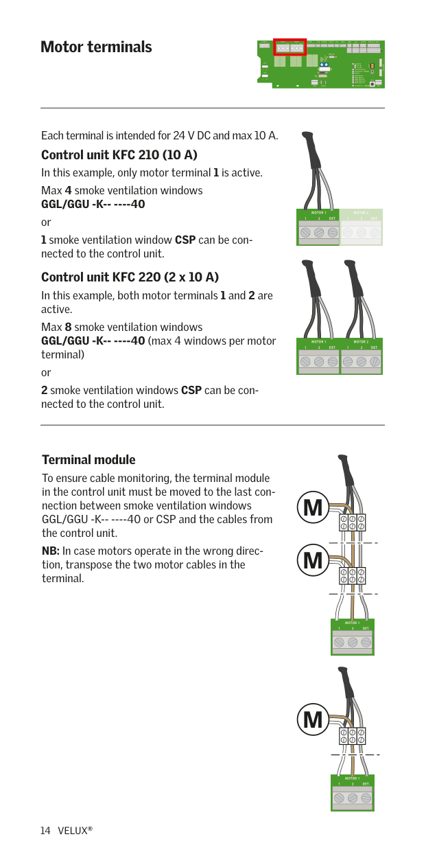
Each terminal is intended for 24 V DC and max 10 A. Control unit KFC 210 (10 A) In this example, only motor terminal 1 is active. Max 4 smoke ventilation windows GGL/GGU -K-- ----40 or
MOTOR 2MOTOR 1
LINK DET.21DET.21
| | |---| | | | |
| | |---| | | | |
Control unit KFC 220 (2 x 10 A) In this example, both motor terminals 1 and 2 are active. Max 8 smoke ventilation windows GGL/GGU -K-- ----40 (max 4 windows per motor terminal) or
MOTOR 2MOTOR 1230V/50Hz
LINK DET.21DET.2PENL
| | |---| | | | |
| | |---| | | | |
Terminal module To ensure cable monitoring, the terminal module in the control unit must be moved to the last connection between smoke ventilation windows GGL/GGU -K-- ----40 or CSP and the cables from the control unit. NB: In case motors operate in the wrong direction, transpose the two motor cables in the terminal.
#### M
| | | |---|---| | | |
#### M
MOTOR 1
DET.21
| | |---| | | | |
| | |---| | | | |
#### M
MOTOR 1
DET.21
| | |---| | | | |
| | |---| | | | |
######## Wiring
LINK FACU 2121PENL
BREAK GLASS POINTRAINRAIN INCOMFORTSMOKERAIN OUTERRORALARMMOTOR 2MOTOR 1230V/50Hz
65432132132121132+–2132132132541
J1
TEMP. FUSE
73˚ C
TIME AUTO CLOSE
COMFORT
TIME OPENNIG
230V
OPERATION
FRONT PANEL
PSU1 OK
PSU2 OK
RAIN SENSOR INPUT
NL
MAINTENANCE BATTERY
230V
RESET
FUSE: 25A
ERROR-MOTOR 1 ERROR-MOTOR 2 ERROR-SMOKE DET. ERROR-BREAK GLASS
NL
RESET
+ – 24V 24V
ERROR-TEMP. FUSE
ALARM ACTIVE
BATTERY
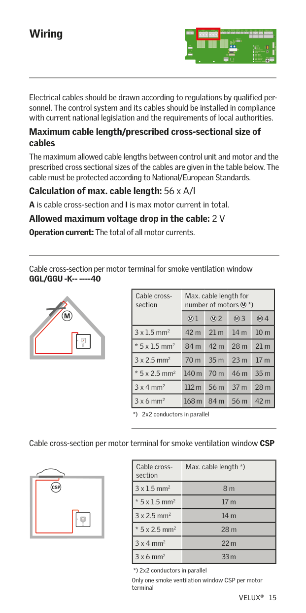
Electrical cables should be drawn according to regulations by qualified personnel. The control system and its cables should be installed in compliance with current national legislation and the requirements of local authorities.
########## Maximum cable length/prescribed cross-sectional size of cables
The maximum allowed cable lengths between control unit and motor and the prescribed cross sectional sizes of the cables are given in the table below. The cable must be protected according to National/European Standards.
Calculation of max. cable length: 56 x A/l A is cable cross-section and I is max motor current in total. Allowed maximum voltage drop in the cable: 2 V Operation current: The total of all motor currents.
Cable cross-section per motor terminal for smoke ventilation window GGL/GGU -K-- ----40
|Cable crosssection|Max. cable length for number of motors *)
|Max. cable length for number of motors *)
|Max. cable length for number of motors *)
|Max. cable length for number of motors *)
| |---|---|---|---|---| |Cable crosssection|1|2|3|4| |3 x 1.5 mm2|42 m|21 m|14 m|10 m| |* 5 x 1.5 mm2|84 m|42 m|28 m|21 m| |3 x 2.5 mm2|70 m|35 m|23 m|17 m| |* 5 x 2.5 mm2|140 m|70 m|46 m|35 m| |3 x 4 mm2|112 m|56 m|37 m|28 m| |3 x 6 mm2|168 m|84 m|56 m|42 m|
Only one smoke ventilation window CSP per motor terminal
Cable cross-section per motor terminal for smoke ventilation window CSP
|Cable crosssection|Max. cable length *)| |---|---| |3 x 1.5 mm2|8 m| |* 5 x 1.5 mm2|17 m| |3 x 2.5 mm2|14 m| |* 5 x 2.5 mm2|28 m| |3 x 4 mm2|22 m| |3 x 6 mm2|33 m|
CSP
######## Setting of switches
LINK FACU 2121PENL
BREAK GLASS POINTRAINRAIN INCOMFORTSMOKERAIN OUTERRORALARMMOTOR 2MOTOR 1230V/50Hz
65432132132121132+–2132132132541
J1
TEMP. FUSE
73˚ C
| | | |---|---| | | |
TIME AUTO CLOSE
COMFORT
TIME OPENNIG
230V
OPERATION
FRONT PANEL
SETUP
PSU1 OK
PSU2 OK
RAIN SENSOR INPUT
NL
MAINTENANCE BATTERY
230V
FUSE: 25A
ERROR-MOTOR 1 ERROR-MOTOR 2 ERROR-SMOKE DET. ERROR-BREAK GLASS
NL
RESET
+ – 24V 24V
ERROR-TEMP. FUSE
ALARM ACTIVE
BATTERY
ONONONON
4444333322221111
SETUPSETUPSETUPSETUPSETUPSETUPSETUPSETUP
ONONONON
4444333322221111
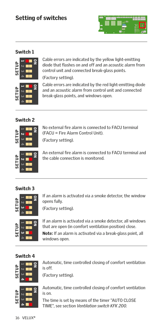
Cable errors are indicated by the yellow light-emitting diode that flashes on and off and an acoustic alarm from control unit and connected break-glass points. (Factory setting). Cable errors are indicated by the red light-emitting diode and an acoustic alarm from control unit and connected break-glass points, and windows open.
No external fire alarm is connected to FACU terminal (FACU = Fire Alarm Control Unit). (Factory setting).
An external fire alarm is connected to FACU terminal and the cable connection is monitored.
If an alarm is activated via a smoke detector, the window opens fully. (Factory setting).
If an alarm is activated via a smoke detector, all windows that are open (in comfort ventilation position) close. Note: If an alarm is activated via a break-glass point, all windows open.
Automatic, time controlled closing of comfort ventilation is off. (Factory setting).
Automatic, time controlled closing of comfort ventilation is on. The time is set by means of the timer "AUTO CLOSE TIME", see section Ventilation switch KFK 200.
######## Operation of and signals from control unit
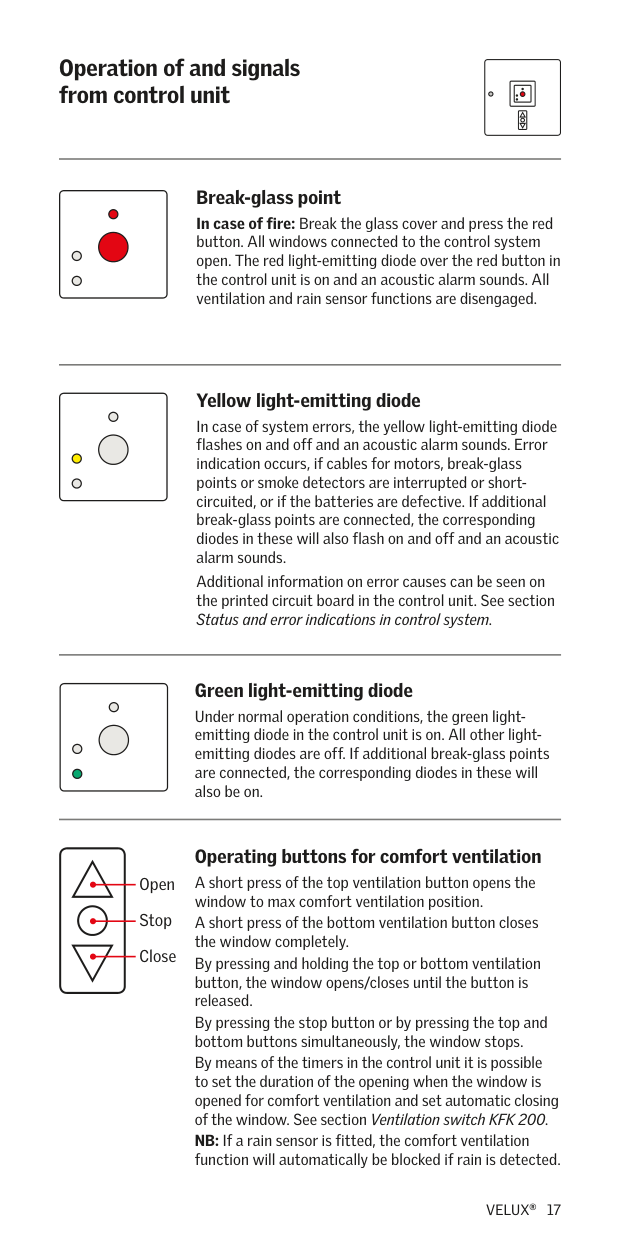
Break-glass point In case of fire: Break the glass cover and press the red button. All windows connected to the control system open. The red light-emitting diode over the red button in the control unit is on and an acoustic alarm sounds. All ventilation and rain sensor functions are disengaged.
########## Yellow light-emitting diode
In case of system errors, the yellow light-emitting diode flashes on and off and an acoustic alarm sounds. Error indication occurs, if cables for motors, break-glass points or smoke detectors are interrupted or shortcircuited, or if the batteries are defective. If additional break-glass points are connected, the corresponding diodes in these will also flash on and off and an acoustic alarm sounds.
Additional information on error causes can be seen on the printed circuit board in the control unit. See section Status and error indications in control system.
########## Green light-emitting diode
Under normal operation conditions, the green lightemitting diode in the control unit is on. All other lightemitting diodes are off. If additional break-glass points are connected, the corresponding diodes in these will also be on.
| | | |---|---| | | | | | | | | |
Open Stop Close
Operating buttons for comfort ventilation A short press of the top ventilation button opens the window to max comfort ventilation position. A short press of the bottom ventilation button closes the window completely. By pressing and holding the top or bottom ventilation button, the window opens/closes until the button is released. By pressing the stop button or by pressing the top and bottom buttons simultaneously, the window stops.
By means of the timers in the control unit it is possible to set the duration of the opening when the window is opened for comfort ventilation and set automatic closing of the window. See section Ventilation switch KFK 200. NB: If a rain sensor is fitted, the comfort ventilation function will automatically be blocked if rain is detected.
######## Back-up batteries
LINK FACU 2121PENL
BREAK GLASS POINTRAINRAIN INCOMFORTSMOKERAIN OUTERRORALARMMOTOR 2MOTOR 1230V/50Hz
65432132132121132+–2132132132541
J1
TEMP. FUSE
73˚ C
| | | |---|---| | | |
TIME AUTO CLOSE
COMFORT
TIME OPENNIG
230V
OPERATION
FRONT PANEL
PSU1 OK
PSU2 OK
RAIN SENSOR INPUT
NL
MAINTENANCE BATTERY
230V
RESET
ERROR-MOTOR 1 ERROR-MOTOR 2 ERROR-SMOKE DET. ERROR-BREAK GLASS
NL
RESET
+ – 24V 24V
ERROR-TEMP. FUSE
ALARM ACTIVE
BATTERY
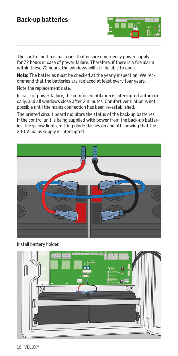
The control unit has batteries that ensure emergency power supply for 72 hours in case of power failure. Therefore, if there is a fire alarm within these 72 hours, the windows will still be able to open. Note: The batteries must be checked at the yearly inspection. We recommend that the batteries are replaced at least every four years. Note the replacement date. In case of power failure, the comfort ventilation is interrupted automatically, and all windows close after 2 minutes. Comfort ventilation is not possible until the mains connection has been re-established. The printed circuit board monitors the status of the back-up batteries. If the control unit is being supplied with power from the back-up batteries, the yellow light-emitting diode flashes on and off showing that the 230 V mains supply is interrupted.
| | | | | | |---|---|---|---|---| | | | | | |
Install battery holder.
| | | |---|---| | | |
######## Mains connection
LINK FACU 2121PENL
BREAK GLASS POINTRAINRAIN INCOMFORTSMOKERAIN OUTERRORALARMMOTOR 2MOTOR 1230V/50Hz
65432132132121132+–2132132132541
J1
TEMP. FUSE
73˚ C
TIME AUTO CLOSE
COMFORT
TIME OPENNIG
230V
OPERATION
FRONT PANEL
PSU1 OK
PSU2 OK
RAIN SENSOR INPUT
NL
MAINTENANCE BATTERY
230V
RESET
ERROR-MOTOR 1 ERROR-MOTOR 2 ERROR-SMOKE DET. ERROR-BREAK GLASS
25A
NL
RESET
+ – 24V 24V
ERROR-TEMP. FUSE
ALARM ACTIVE
BATTERY
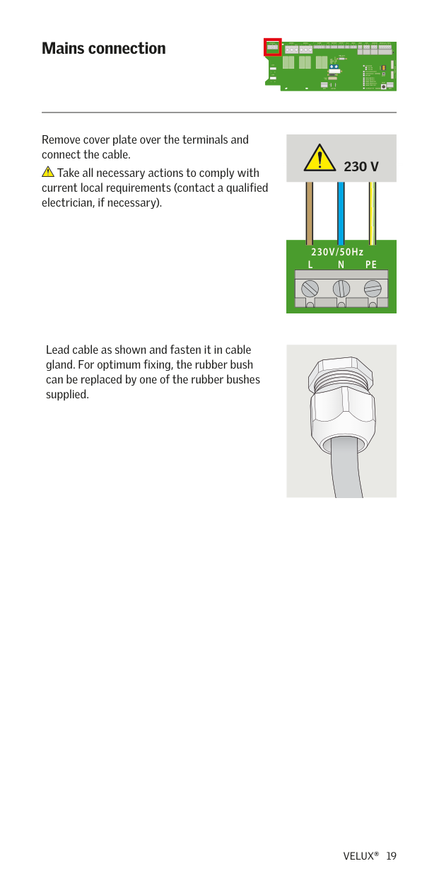
Remove cover plate over the terminals and connect the cable.
230 V
Take all necessary actions to comply with current local requirements (contact a qualified electrician, if necessary).
230V/50Hz
PENL
Lead cable as shown and fasten it in cable gland. For optimum fixing, the rubber bush can be replaced by one of the rubber bushes supplied.
OPERATION The printed circuit board monitors the present status of the control system. Normal operation condition of the control unit is indicated with a green light-emitting diode.
########## PSU1 OK
The printed circuit board monitors the present status of the power
The light-emitting diode indicates that the motor terminal is being supplied with power from the integrated power supply.
If the 230 V mains supply to the control unit is interrupted, the printed circuit board automatically switches to battery supply and the diode is turned off.
PSU2 OK
The printed circuit board monitors the present status of the power
The light-emitting diode indicates that the motor terminal is being supplied with power from the integrated power supply.
If the 230 V mains supply to the control unit is interrupted, the printed circuit board automatically switches to battery supply and the diode is turned off.
RAIN SENSOR - INPUT The printed circuit board monitors the present status of the rain sensor. If the connected rain sensor detects rain, the yellow light-emitting diode is on and any window opened for comfort ventilation closes. When the rain has stopped, the yellow light-emitting diode is turned off and the window can be opened for comfort ventilation again after two minutes.
########## MAINTENANCE
The printed circuit board monitors the time between inspection periods. If more than 15 months have passed since the last inspection, the yellow light-emitting diode is on and an acoustic alarm sounds. During the inspection, the system is reset by pressing the button at the right for at least 5 seconds. After this, 15 months will pass before the lightemitting diode comes on again, if the service time is exceeded. Exceeded service intervals are also error indicated with a yellow light-emitting diode in the integrated break-glass point and possible additional breakglass points and an acoustic alarm.
######## in control system
LINK 2121PENL
BREAK GLASS POINTRAINRAIN INCOMFORTSMOKERAIN OUTERRORALARMMOTOR 2MOTOR 1230V/50Hz
65432132132121132+–2132132132541
J1
TEMP. FUSE
73˚ C
TIME AUTO CLOSE
COMFORT
TIME OPENNIG
230V
OPERATION
FRONT PANEL
PSU1 OK
PSU2 OK
RAIN SENSOR INPUT
NL
MAINTENANCE BATTERY
230V
RESET
FUSE:
ERROR-MOTOR 1 ERROR-MOTOR 2 ERROR-SMOKE DET. ERROR-BREAK GLASS
NL
RESET
+ – 24V 24V
ERROR-TEMP. FUSE
ALARM ACTIVE
BATTERY
########## BATTERY
The printed circuit board monitors the status of the back-up batteries. If the control unit is supplied with power from the back-up batteries, the yellow light-emitting diode flashes on and off showing that the 230 V mains supply is interrupted.
If the batteries are not connected or defective, the yellow light-emitting diode is on permanently showing that the batteries should be connected or replaced. This is also the case if the 25 A fuse is defective. In all three cases, an acoustic alarm sounds.
Note: If the back-up batteries are heavily discharged, the yellow lightemitting diode flashes on and off and the green OPERATION diode on the circuit board is on until the batteries are fully charged.
Note: The battery circuit is measured at start-up. It can take up to
########## ERROR - MOTOR 1
The printed circuit board monitors for defects in the cable from motor
If the cable is interrupted, the yellow light-emitting diode flashes on and off. If the cable is short-circuited, the yellow light-emitting diode is on permanently. The error is also indicated in the integrated break-glass point and possible additional break-glass points. ERROR - MOTOR 2
The printed circuit board monitors for defects in the cable from motor
If the cable is interrupted, the yellow light-emitting diode flashes on and off. If the cable is short-circuited, the yellow light-emitting diode is on permanently. The error is also indicated in the integrated break-glass point and possible additional break-glass points.
ERROR - SMOKE DETECTOR The printed circuit board monitors for defects in the cable to any smoke detectors that are connected. If the cable to the connected smoke detector(s) is interrupted, the yellow light-emitting diode flashes on and off. If the cable is short-circuited, the yellow light-emitting diode is on permanently. The error is also indicated in the integrated break-glass point and possible additional break-glass points.
ERROR - BREAK-GLASS POINT The printed circuit board monitors for defects in the cable to any breakglass points that are connected. If the cable to the connected break-glass point(s) is interrupted, the yellow light-emitting diode flashes on and off. If the cable is short-circuited, the yellow light-emitting diode is on permanently. The error is also indicated in the integrated break-glass point and possible additional break-glass points.
ERROR - TEMP. FUSE The printed circuit board monitors the temperature in the control unit. If the temperature in the control unit rises above 70 ˚C, the temperature fuse on the printed circuit board is activated and all connected windows open for smoke ventilation. The yellow light-emitting diode is on permanently until the printed circuit board has been replaced. After replacing the printed circuit board, the installation must be service tested thoroughly to ensure that the system works correctly. The error is also indicated in the integrated break-glass point and possible additional break-glass points.
ALARM - ACTIVE The red light-emitting diode on the front of the control unit is on permanently when the smoke ventilation function has been activated (from break-glass point, smoke detector or external fire alarm). The alarm can be reset by pressing the button at the right. After this, the light-emitting diode on the printed circuit board and in all breakglass points are turned off.
########## ERROR - COMFORT VENTILATION
After an alarm or a power failure, it will take at least 2 minutes before the comfort ventilation can be activated again.
DET.2121PENL
J1
TEMP. FUSE
73˚ C
TIME AUTO CLOSE
COMFORT
TIME OPENNIG
230V
OPERATION
FRONT PANEL
SETUP
PSU1 OK
PSU2 OK
RAIN SENSOR INPUT
NL
MAINTENANCE BATTERY
230V
RESET
25A
NL
RESET
+ – 24V 24V
ERROR-TEMP. FUSE
ALARM ACTIVE
BATTERY
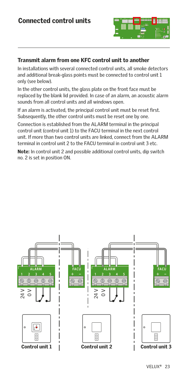
Transmit alarm from one KFC control unit to another In installations with several connected control units, all smoke detectors and additional break-glass points must be connected to control unit 1 only (see below). In the other control units, the glass plate on the front face must be replaced by the blank lid provided. In case of an alarm, an acoustic alarm sounds from all control units and all windows open. If an alarm is activated, the principal control unit must be reset first. Subsequently, the other control units must be reset one by one.
Connection is established from the ALARM terminal in the principal control unit (control unit 1) to the FACU terminal in the next control unit. If more than two control units are linked, connect from the ALARM terminal in control unit 2 to the FACU terminal in control unit 3 etc. Note: In control unit 2 and possible additional control units, dip switch no. 2 is set in position ON.
RAIN OUTALARMMOTOR 2MOTOR 1
LINK DET.21DET.2
FACURAIN IN SMOKERAIN OUTALARM 132541
LINK FACU RAINRAIN IN COMFORTSMOKERAIN OUTERROR
LINK FACU DET.21
RAIN OUTALARMMOTOR 2
211+–213213132541
321132+–12132
+ –21321324
24 V
24 V
0 V
0 V
BREAK GLASS POINTRAIN INCOMFORTRAIN OUT
65432132132121132+–21321321325412121PENL
TEMP. FUSE
73˚ C
TIME AUTO CLOSE
COMFORT
TIME OPENNIG
230V
OPERATION
FRONT PANEL
PSU2 OK
RAIN SENSOR INPUT MAINTENANCE
NL
230V
RESET
ERROR-MOTOR 1
NL
ERROR-SMOKE DET. ERROR-BREAK GLASS
RESET
+ – 24V 24V
BATTERY
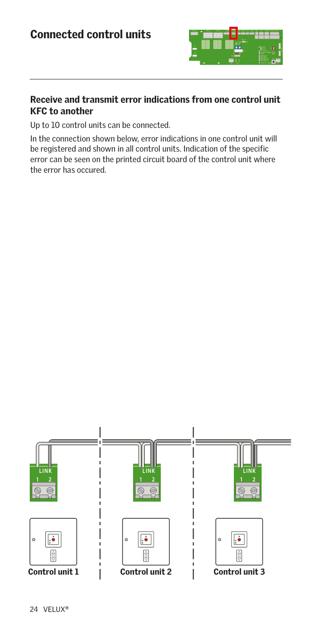
########## Receive and transmit error indications from one control unit KFC to another
Up to 10 control units can be connected. In the connection shown below, error indications in one control unit will be registered and shown in all control units. Indication of the specific error can be seen on the printed circuit board of the control unit where the error has occured.
RAIN OUTALARMMOTOR 2 212
LINK FACU DET.2
LINK DET.21
LINK FACU RAIN
MOTOR 2MOTOR 1
32–121
+ –21
J1
TEMP. FUSE
73˚ C
| | | |---|---| | | |
TIME AUTO CLOSE
COMFORT
TIME OPENNIG
230V
OPERATION
FRONT PANEL
PSU1 OK
PSU2 OK
RAIN SENSOR INPUT
NL
MAINTENANCE BATTERY
230V
RESET
FUSE: 25A
NL
RESET
+ – 24V 24V
ERROR-TEMP. FUSE
ALARM ACTIVE
BATTERY
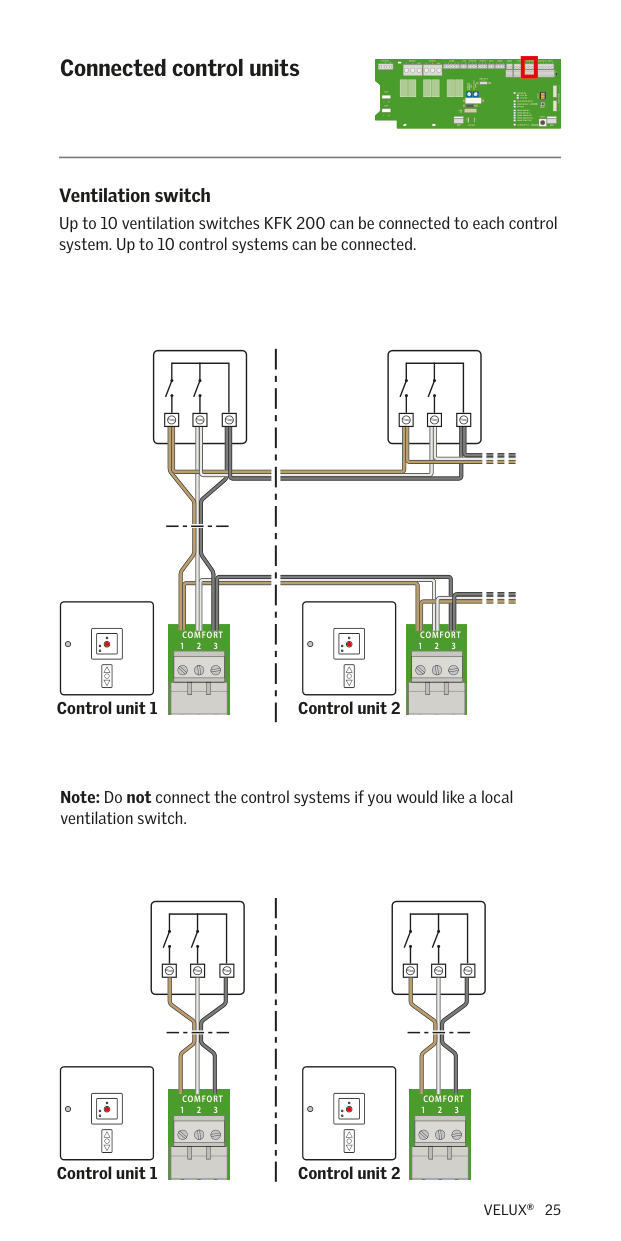
Ventilation switch Up to 10 ventilation switches KFK 200 can be connected to each control system. Up to 10 control systems can be connected.
FACURAIN IN COMFORTSMOKERAIN OUTERROR 5332112 BREAK GLASS POINTCOMFORTSMOKE
3213122+23211
| | | | | | | | | |---|---|---|---|---|---|---|---| | | | | | | | | | | | | | | | | | | | | | | | | | | |
| | | | | | | | | | | | | | | | |---|---|---|---|---|---|---|---|---|---|---|---|---|---|---| | | | | | | | | | | | | | | | | | | | | | | | | | | | | | | | |
J1
Control unit 1
Control unit 2
Note: Do not connect the control systems if you would like a local ventilation switch.
LINK FACURAIN IN COMFORTSMOKERAIN OUTERROR
BREAK GLASS POINTCOMFORTSMOKE
321312+2311
5332112
| | | | | | | | | |---|---|---|---|---|---|---|---| | | | | | | | | | | | | | | | | | | | | | | | | | | |
| | | | | | | | | | | | | | | | |---|---|---|---|---|---|---|---|---|---|---|---|---|---|---| | | | | | | | | | | | | | | | | | | | | | | | | | | | | | | | |
J1
Control unit 1
Control unit 2
TEMP. FUSE
73˚ C
TIME AUTO CLOSE
COMFORT
TIME OPENNIG
230V
OPERATION
FRONT PANEL
SETUP
PSU2 OK
RAIN SENSOR INPUT MAINTENANCE BATTERY
NL
230V
RESET
ERROR-MOTOR 1 ERROR-MOTOR 2 ERROR-SMOKE DET. ERROR-BREAK GLASS
NL
+ – 24V 24V
BATTERY
Rain sensor The product can be purchased separately. Connection
The rain sensor is connected to the control system by means of a 3-core cable with a minimum cross-section of 0.5 mm2. This cable can be up to 100 m long.
NB: If the rain sensor has been activated, it will take at least 2 minutes before the comfort ventilation can be activated again. The example below shows a cable connection with several control systems but only one rain sensor.
| | | |---|---| | | |
LINK FACU BREAK GLASS POINTRAINRAIN INCOMFORTSMOKERAIN OUTERROR
LINK FACU DET.
RAINRAIN INSMOKERAIN OUTERRORALARM
32121132+–21321321
11213213
########### Control unit 2 Control unit 1
DET.2121PENL
TEMP. FUSE
73˚ C
TIME AUTO CLOSE
COMFORT
TIME OPENNIG
230V
OPERATION
FRONT PANEL
SETUP
PSU2 OK
RAIN SENSOR INPUT
NL
230V
BATTERY
RESET
ERROR-MOTOR 2 ERROR-SMOKE DET. ERROR-BREAK GLASS
NL
+ – 24V 24V
BATTERY
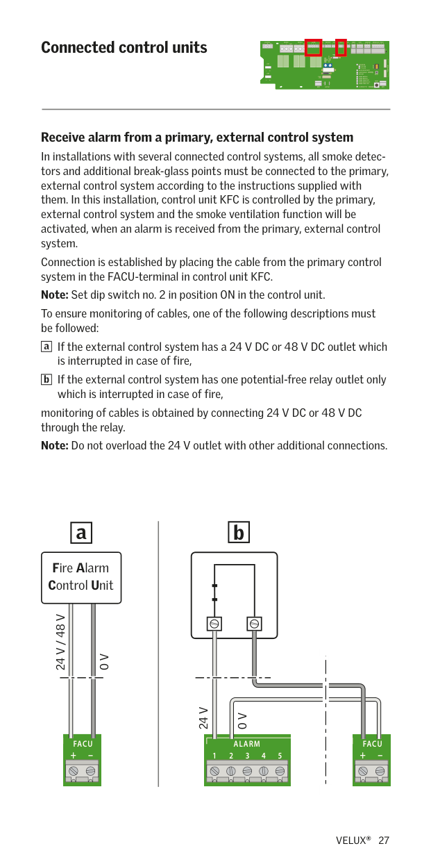
Receive alarm from a primary, external control system In installations with several connected control systems, all smoke detectors and additional break-glass points must be connected to the primary, external control system according to the instructions supplied with them. In this installation, control unit KFC is controlled by the primary, external control system and the smoke ventilation function will be activated, when an alarm is received from the primary, external control system. Connection is established by placing the cable from the primary control system in the FACU-terminal in control unit KFC. Note: Set dip switch no. 2 in position ON in the control unit.
To ensure monitoring of cables, one of the following descriptions must be followed:
If the external control system has a 24 V DC or 48 V DC outlet which is interrupted in case of fire, If the external control system has one potential-free relay outlet only which is interrupted in case of fire,
|a| |---|
|b| |---|
monitoring of cables is obtained by connecting 24 V DC or 48 V DC through the relay. Note: Do not overload the 24 V outlet with other additional connections.
|b| |---|
|a| |---|
Fire Alarm Control Unit
24 V / 48 V
0 V
24 V
0 V
FACU BREAK GLASS POINTRAINCOMFORT
RAIN INRAIN OUTALARMMOTOR 2MOTOR 1
LINK FACU 2
RAIN INRAIN OUTMOTOR 2

23+–
3+–212125
1332541DET.
J1
TEMP. FUSE
73˚ C
TIME AUTO CLOSE
COMFORT
TIME OPENNIG
230V
OPERATION
FRONT PANEL
SETUP
PSU1 OK
PSU2 OK
RAIN SENSOR INPUT
NL
MAINTENANCE BATTERY
230V
RESET
FUSE: 25A
NL
RESET
+ – 24V 24V
ERROR-TEMP. FUSE
ALARM ACTIVE
BATTERY
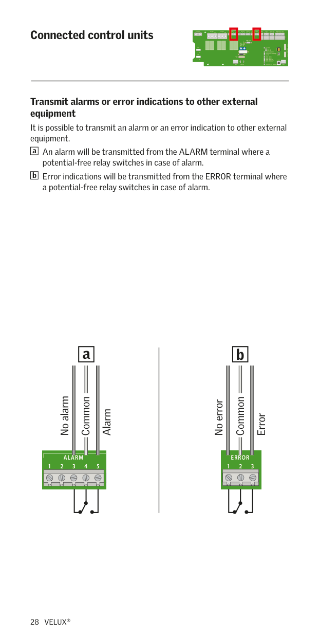
########## Transmit alarms or error indications to other external equipment
It is possible to transmit an alarm or an error indication to other external equipment.
An alarm will be transmitted from the ALARM terminal where a potential-free relay switches in case of alarm. Error indications will be transmitted from the ERROR terminal where a potential-free relay switches in case of alarm.
|a| |---|
|b| |---|
|a| |---|
|b| |---|
No alarm
Common
Alarm
No error
Common
Error
LINK ERRORALARM
FACURAIN OUT ERRORALARM
1 2–32541
1 3213254
######## Replacement of frame in control unit
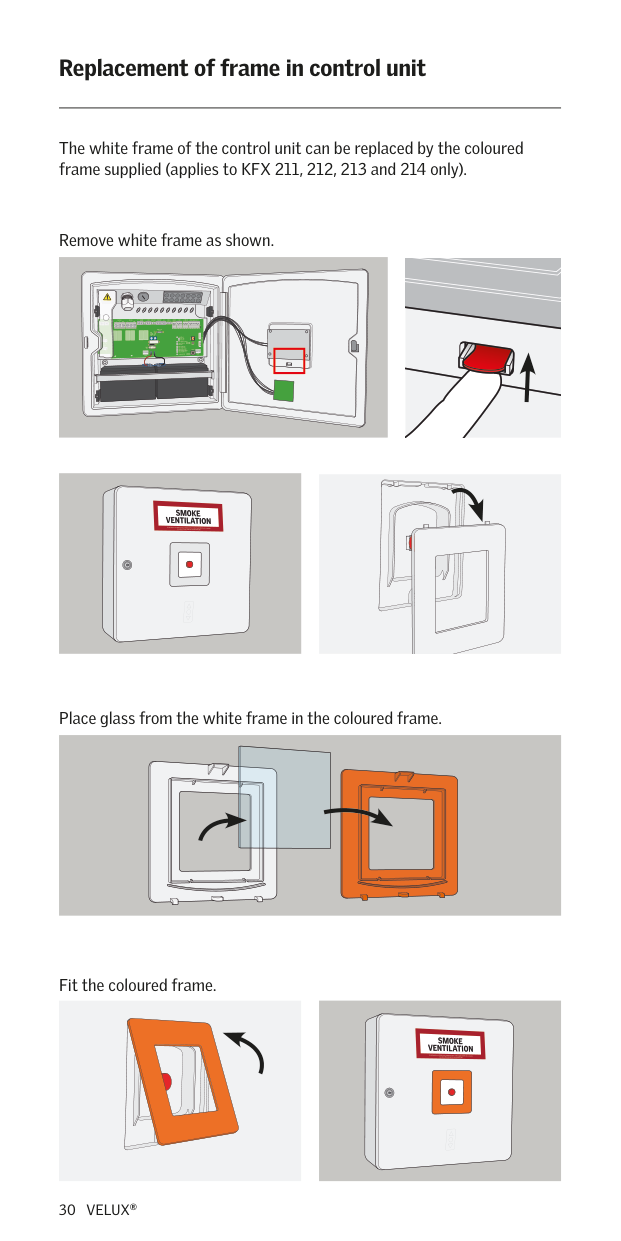
The white frame of the control unit can be replaced by the coloured frame supplied (applies to KFX 211, 212, 213 and 214 only).
Remove white frame as shown.
Place glass from the white frame in the coloured frame.
Fit the coloured frame.
######## Technical data
Primary voltage: 230 V AC/50 Hz (±10%) Power consumption:
− KFC 210 max 250 W − KFC 220 max 500 W
Secondary voltage: 24 V DC (21-26.4 V DC) Ripple voltage: max 2 Vpp Load max.:
− 10 A (KFC 210) − 2 x 10 A (KFC 220) − ED 10% per 10 minutes
Alarm and error relays: Contact rating 24 V DC, 1 A Battery backup:
− 2 x 12 V/7.2 A h − Expected battery lifetime: 4 years
Interruption time between mains supply and batteries: Max 2.5 sec Fuses:
− Battery fuse 25 A − Thermo fuse 73°C
Status LED in break-glass point: − Green light, system OK − Yellow light, error. For details, see page 15 and 18-20 − Red light, alarm active
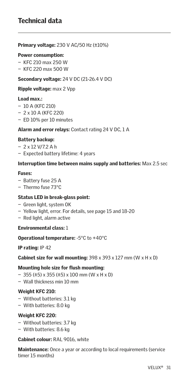
Environmental class: 1 Operational temperature: -5°C to +40°C IP rating: IP 42 Cabinet size for wall mounting: 398 x 393 x 127 mm (W x H x D) Mounting hole size for flush mounting:
− 355 (±5) x 355 (±5) x 100 mm (W x H x D) − Wall thickness min 10 mm
Weight KFC 210: − Without batteries: 3.1 kg − With batteries: 8.0 kg
Weight KFC 220: − Without batteries: 3.7 kg − With batteries: 8.6 kg
Cabinet colour: RAL 9016, white Maintenance: Once a year or according to local requirements (service timer 15 months)
AR: VELUX Argentina S.A. 348 4 639944
BA: VELUX Bosna i Hercegovina d.o.o.
033/626 493, 626 494 BE: VELUX Belgium
(010) 42.09.09
BG: ВЕЛУКС България ЕООД
02/955 99 30
BY: Унитарное предприятие
(017) 217 73 85
CA: VELUX Canada Inc.
1 800 88-VELUX (888-3589) CH: VELUX Schweiz AG
062 289 44 45
CL: VELUX Chile Limitada
2 953 6789
CN: VELUX (CHINA) CO. LTD. 0316-607 27 27
CZ: VELUX Česká republika, s.r.o.
531 015 511
DE: VELUX Deutschland GmbH 01806 / 33 33 99 Festnetz: 0,20 €/Anruf Mobilfunk: max. 0,60 €/Anruf
DK: VELUX Danmark A/S
45 16 45 16
EE: VELUX Eesti OÜ
621 7790
ES: VELUX Spain, S.A.
91 509 71 00
FI: VELUX Suomi Oy
0207 290 800
FR: VELUX France 0821 02 15 15 0,119€ TTC/min
GB: VELUX Company Ltd.
01592 778 225
HR: VELUX Hrvatska d.o.o.
01/5555 444
HU: VELUX Magyarország Kft.
(06/1) 436-0601
IE: VELUX Company Ltd. 01 848 8775
IT: VELUX Italia s.p.a.
045/6173666
JP: VELUX-Japan Ltd.
0570-00-8145
LT: VELUX Lietuva, UAB
(85) 270 91 01
LV: VELUX Latvia SIA
67 27 77 33
NL: VELUX Nederland B.V.
030 - 6 629 629
NO: VELUX Norge AS
22 51 06 00
NZ: VELUX New Zealand Ltd.
0800 650 445 PL: VELUX Polska Sp. z o.o.
(022) 33 77 000 / 33 77 070 PT: VELUX Portugal, Lda 21 880 00 60 RO: VELUX România S.R.L. 0-8008-83589
RS: VELUX Srbija d.o.o.
011 20 57 500 RU: ЗАО ВЕЛЮКС
(495) 640 87 20
SE: VELUX Svenska AB
042/20 83 80 SI: VELUX Slovenija d.o.o. 01 724 68 68
SK: VELUX Slovensko, s.r.o.
(02) 33 000 555
TR: VELUX Çatı Pencereleri Ticaret Limited Şirketi 0 216 302 54 10
UA: ТОВ "ВЕЛЮКС Україна"
(044) 2916070
US: VELUX America LLC
1-800-88-VELUX
######### www.velux.com
INSTALLATION INSTRUCTIONS FOR KFX/KFC. ©2014, 2016 VELUX GROUP ® VELUX AND THE VELUX LOGO ARE REGISTERED TRADEMARKS USED UNDER LICENCE BY THE VELUX GROUP