
Volkswagen Polo 2009 2017 Fuses And Fuse Box Diagram And Location
Ask AI
— answers from the official manualAnswers from the official manual.
Common questions
Common Questions
10 totalWhere is the fuse box located on my Volkswagen Polo?
The fuse box can be found under the dashboard on the driver's side, and there may also be a second smaller fuse box behind the glove compartment. (Page 1)
How do I identify if my Polo has dual clutch gear shift?
Check for the presence of Fuse 13 with a nominal value of 5A and labeled 'Mechatronic unit for dual clutch gearbox -J743-'. Its existence indicates your vehicle is equipped with this feature. (Page 3)
What is the fuse number for cruise control system switch?
Fuse 10 on fuse holder B (-SB10-) is designated for the Cruise Control System Switch, along with several other components like brake light switch and steering column combination switch. (Page 3)
How do I check fuse replacements in my Polo?
Each fuse has a specific circuit designation and nominal value, use this information to identify the faulty fuse by comparing with diagrams and labels provided in your model’s documentation. (Pages 1-7)
Which fuse should be checked if my windscreen washer pump stops working?
Inspect Fuse 7 or Fuse 17 on the fuse holder B as these may affect operations of windshield and rear window washer pumps. (Pages 2-3)
What does Fuse 4 cover in my Polo?
Fuse 4 is associated with steering column combination switch -E595-, relevant to the time period up until May 2011. (Page 2)
Full Manual
8 pages
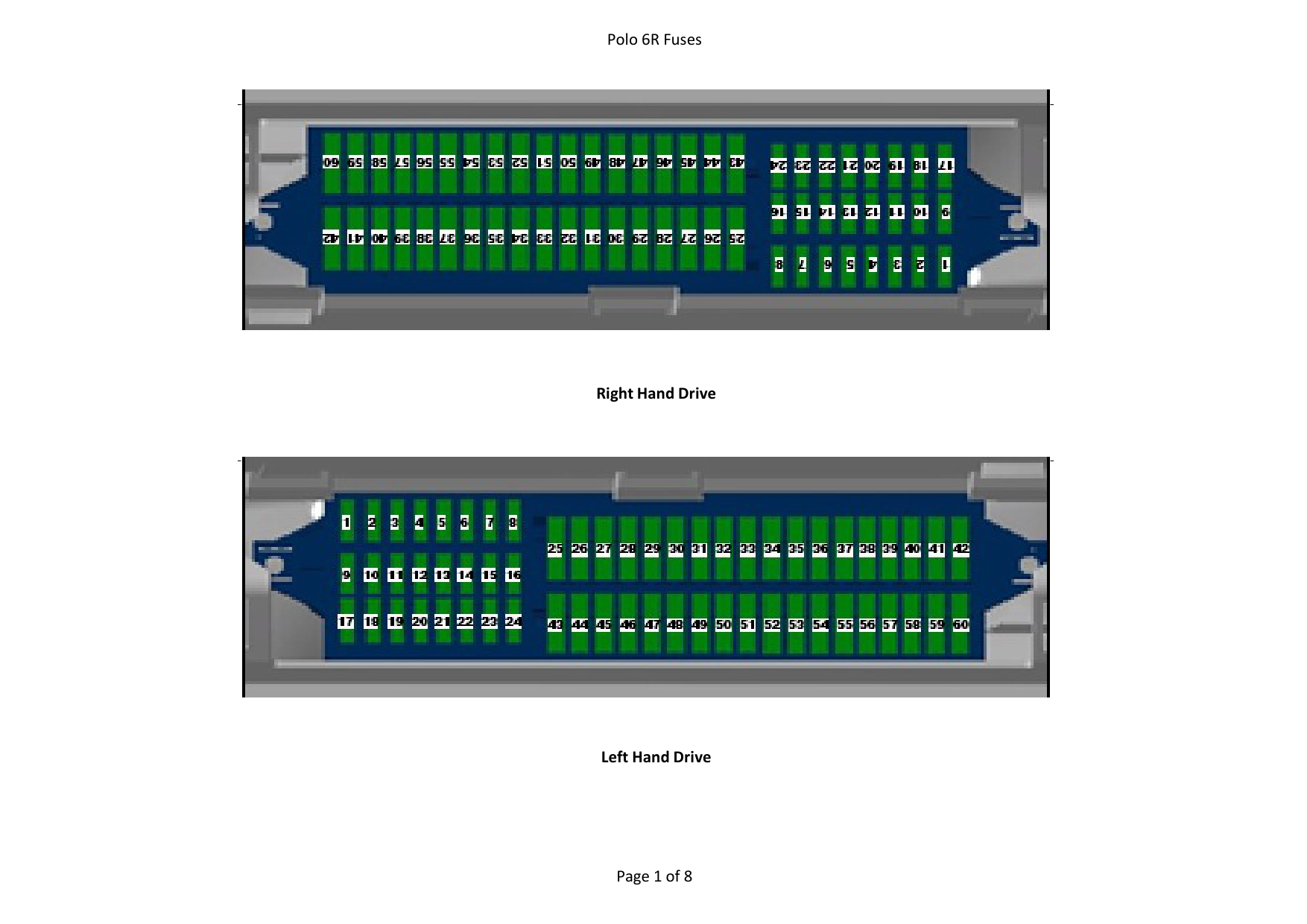


Right Hand Drive


Left Hand Drive
|No.|Current Flow Diagram designation|Nominal value|Function/component|Terminal| |---|---|---|---|---|
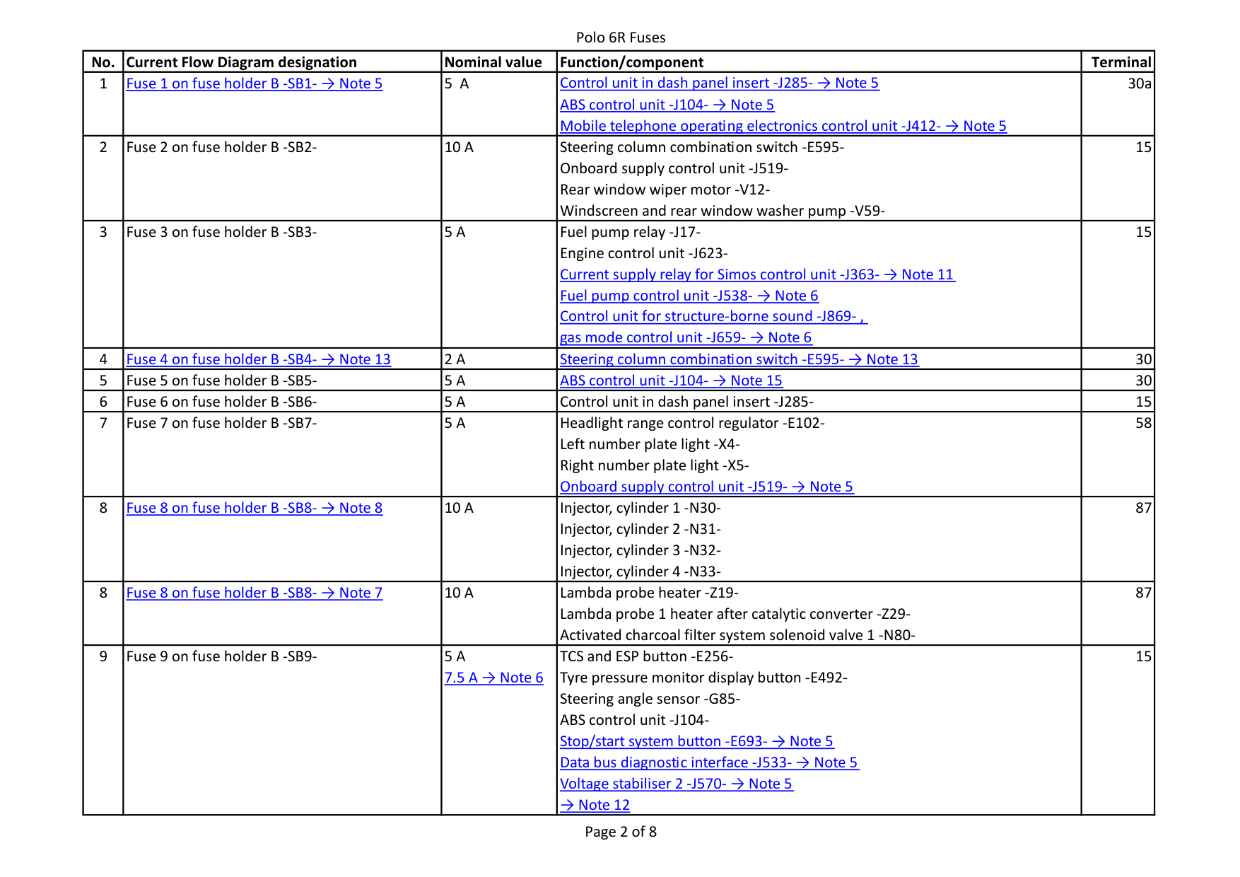
|1|Fuse 1 on fuse holder B -SB1- → Note 5
|5 A|Control unit in dash panel insert -J285- → Note 5 ABS control unit -J104- → Note 5 Mobile telephone operating electronics control unit -J412- → Note 5
|30a| |2|Fuse 2 on fuse holder B -SB2-|10 A|Steering column combination switch -E595Onboard supply control unit -J519Rear window wiper motor -V12Windscreen and rear window washer pump -V59-|15| |3|Fuse 3 on fuse holder B -SB3-|5 A|Fuel pump relay -J17Engine control unit -J623Current supply relay for Simos control unit -J363- → Note 11 Fuel pump control unit -J538- → Note 6 Control unit for structure-borne sound -J869- , gas mode control unit -J659- → Note 6
|15| |4|Fuse 4 on fuse holder B -SB4- → Note 13
|2 A|Steering column combination switch -E595- → Note 13
|30| |5|Fuse 5 on fuse holder B -SB5-|5 A|ABS control unit -J104- → Note 15
|30| |6|Fuse 6 on fuse holder B -SB6-|5 A|Control unit in dash panel insert -J285-|15| |7|Fuse 7 on fuse holder B -SB7-|5 A|Headlight range control regulator -E102Left number plate light -X4Right number plate light -X5Onboard supply control unit -J519- → Note 5
|58| |8|Fuse 8 on fuse holder B -SB8- → Note 8
|10 A|Injector, cylinder 1 -N30-
Injector, cylinder 2 -N31-
Injector, cylinder 3 -N32-
Injector, cylinder 4 -N33-
|87| |8|Fuse 8 on fuse holder B -SB8- → Note 7
|10 A|Lambda probe heater -Z19Lambda probe 1 heater after catalytic converter -Z29Activated charcoal filter system solenoid valve 1 -N80-|87| |9|Fuse 9 on fuse holder B -SB9-|5 A 7.5 A → Note 6
|Data bus diagnostic interface -J533- → Note 5 Voltage stabiliser 2 -J570- → Note 5
TCS and ESP button -E256Tyre pressure monitor display button -E492Steering angle sensor -G85ABS control unit -J104Stop/start system button -E693- → Note 5
→ Note 12
|15|
|No.|Current Flow Diagram designation|Nominal value|Function/component|Terminal| |---|---|---|---|---|
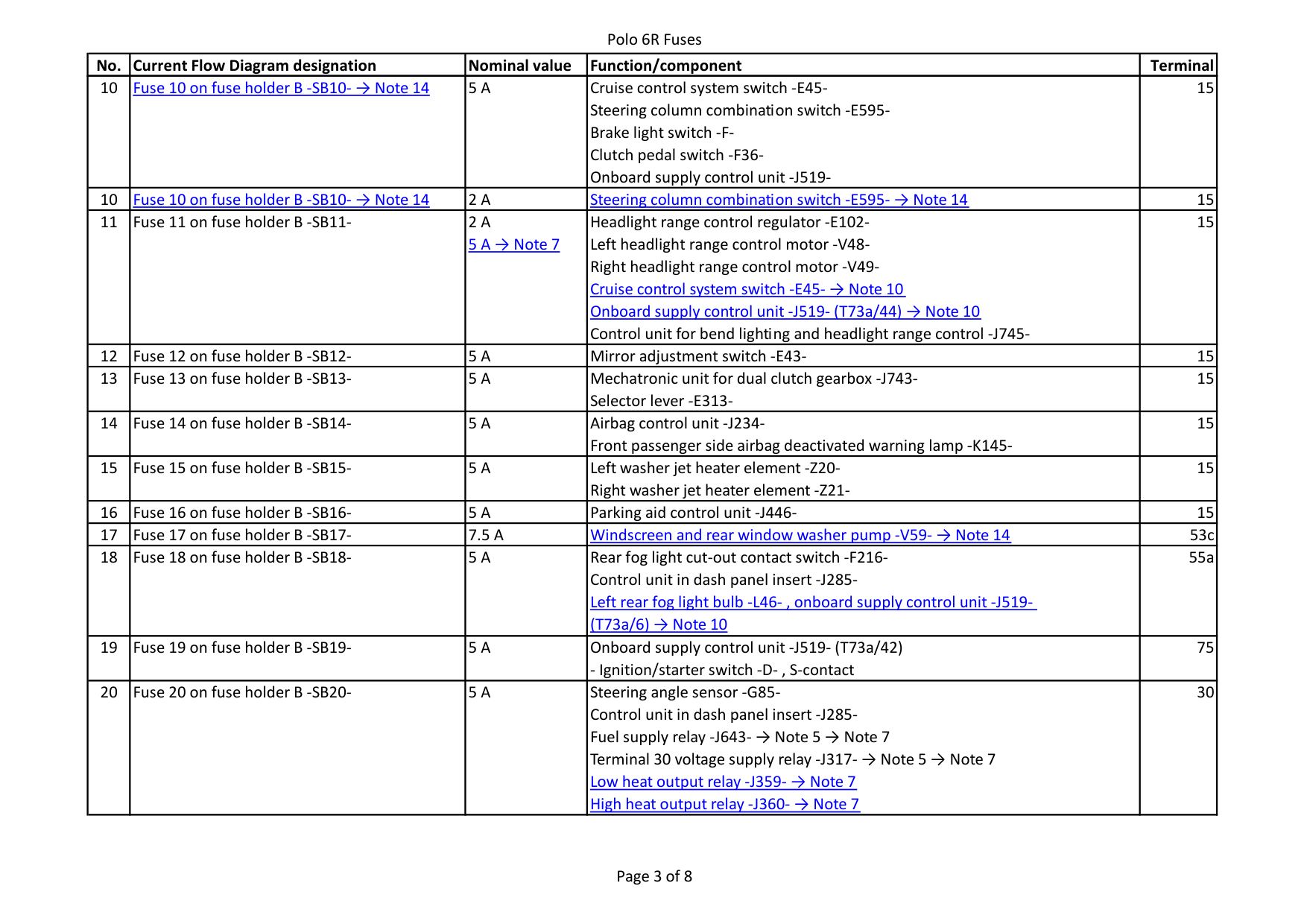
|10|Fuse 10 on fuse holder B -SB10- → Note 14
|5 A|Cruise control system switch -E45Steering column combination switch -E595Brake light switch -FClutch pedal switch -F36Onboard supply control unit -J519-|15| |10|Fuse 10 on fuse holder B -SB10- → Note 14
|2 A|Steering column combination switch -E595- → Note 14
|15| |11|Fuse 11 on fuse holder B -SB11-|2 A 5 A → Note 7
|Headlight range control regulator -E102Left headlight range control motor -V48Right headlight range control motor -V49-
Cruise control system switch -E45- → Note 10 Onboard supply control unit -J519- (T73a/44) → Note 10 Control unit for bend lighting and headlight range control -J745-
|15| |12|Fuse 12 on fuse holder B -SB12-|5 A|Mirror adjustment switch -E43-|15| |13|Fuse 13 on fuse holder B -SB13-|5 A|Mechatronic unit for dual clutch gearbox -J743Selector lever -E313-|15| |14|Fuse 14 on fuse holder B -SB14-|5 A|Airbag control unit -J234Front passenger side airbag deactivated warning lamp -K145-|15| |15|Fuse 15 on fuse holder B -SB15-|5 A|Left washer jet heater element -Z20Right washer jet heater element -Z21-|15| |16|Fuse 16 on fuse holder B -SB16-|5 A|Parking aid control unit -J446-|15| |17|Fuse 17 on fuse holder B -SB17-|7.5 A|Windscreen and rear window washer pump -V59- → Note 14
|53c| |18|Fuse 18 on fuse holder B -SB18-|5 A|Left rear fog light bulb -L46- , onboard supply control unit -J519(T73a/6) → Note 10
Rear fog light cut-out contact switch -F216Control unit in dash panel insert -J285-|55a| |19|Fuse 19 on fuse holder B -SB19-|5 A|- Ignition/starter switch -D- , S-contact
Onboard supply control unit -J519- (T73a/42)|75| |20|Fuse 20 on fuse holder B -SB20-|5 A|High heat output relay -J360- → Note 7
Steering angle sensor -G85Control unit in dash panel insert -J285Fuel supply relay -J643- → Note 5 → Note 7 Terminal 30 voltage supply relay -J317- → Note 5 → Note 7 Low heat output relay -J359- → Note 7
|30|
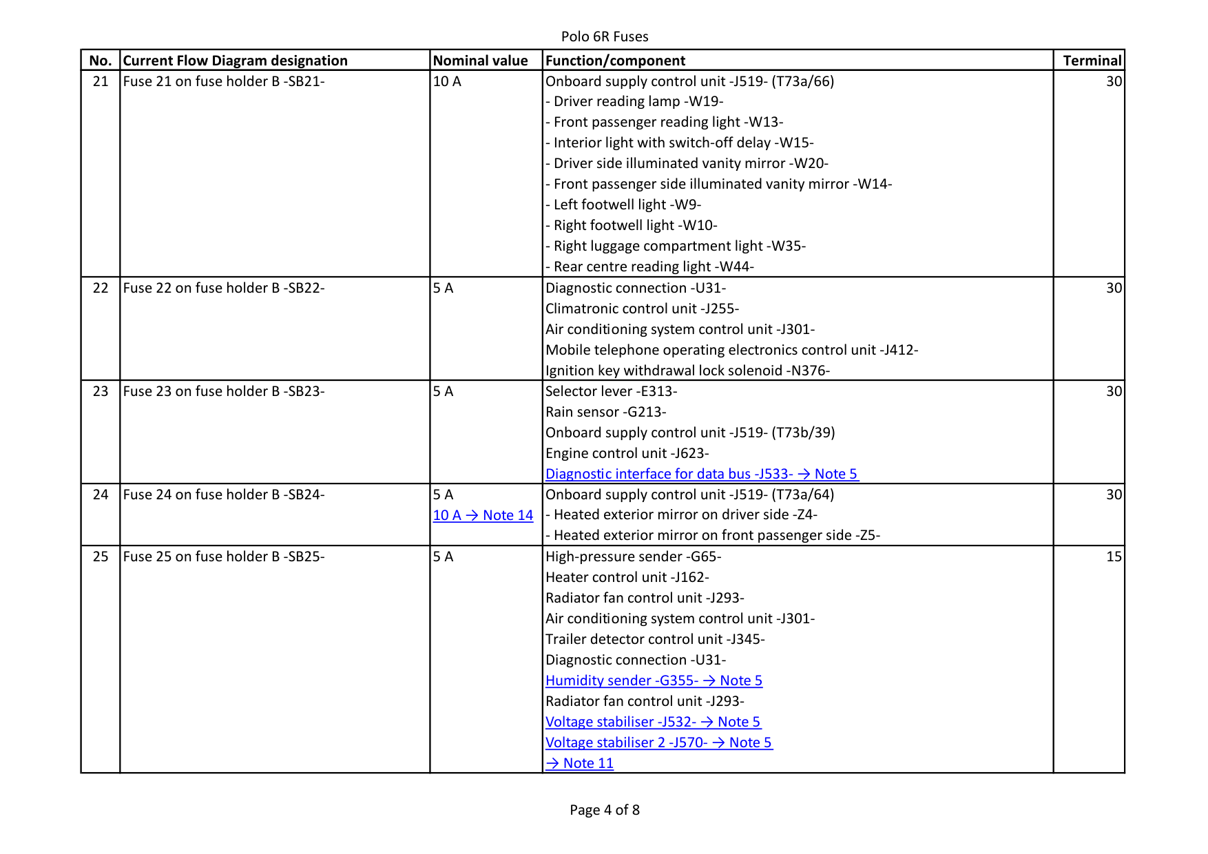
|No.|Current Flow Diagram designation|Nominal value|Function/component|Terminal| |---|---|---|---|---| |21|Fuse 21 on fuse holder B -SB21-|10 A|- Driver reading lamp -W19-
- Front passenger reading light -W13-
Onboard supply control unit -J519- (T73a/66)
- Interior light with switch-off delay -W15-
- Driver side illuminated vanity mirror -W20-
- Front passenger side illuminated vanity mirror -W14-
- Left footwell light -W9-
- Right footwell light -W10-
- Right luggage compartment light -W35-
- Rear centre reading light -W44-
|30| |22|Fuse 22 on fuse holder B -SB22-|5 A|Diagnostic connection -U31Climatronic control unit -J255Air conditioning system control unit -J301Mobile telephone operating electronics control unit -J412Ignition key withdrawal lock solenoid -N376-|30| |23|Fuse 23 on fuse holder B -SB23-|5 A|Diagnostic interface for data bus -J533- → Note 5
Selector lever -E313Rain sensor -G213Onboard supply control unit -J519- (T73b/39) Engine control unit -J623-|30| |24|Fuse 24 on fuse holder B -SB24-|5 A 10 A → Note 14
|Onboard supply control unit -J519- (T73a/64)
- Heated exterior mirror on driver side -Z4-
- Heated exterior mirror on front passenger side -Z5-
|30| |25|Fuse 25 on fuse holder B -SB25-|5 A|Diagnostic connection -U31Humidity sender -G355- → Note 5 Radiator fan control unit -J293Voltage stabiliser -J532- → Note 5
→ Note 11
High-pressure sender -G65Heater control unit -J162Radiator fan control unit -J293Air conditioning system control unit -J301Trailer detector control unit -J345-
Voltage stabiliser 2 -J570- → Note 5
|15|
|No.|Current Flow Diagram designation|Nominal value|Function/component|Terminal| |---|---|---|---|---| |26|Fuse 26 on fuse holder B -SB26-|7.5 A|Starter motor relay 2 -J907- → Note 5
Air mass meter -G70Oil level and oil temperature sender -G266Power steering control unit -J500Crankcase breather heater element -N79Starter motor relay 1 -J906- → Note 5
|15| |27|Fuse 27 on fuse holder B -SB27-|7.5 A|Reversing light switch -F4-|15| |28|Fuse 28 on fuse holder B -SB28-|10 A|Lambda probe heater -Z19Lambda probe 1 heater after catalytic converter -Z29-
Lambda probe -G39Lambda probe after catalytic converter -G130-|87|
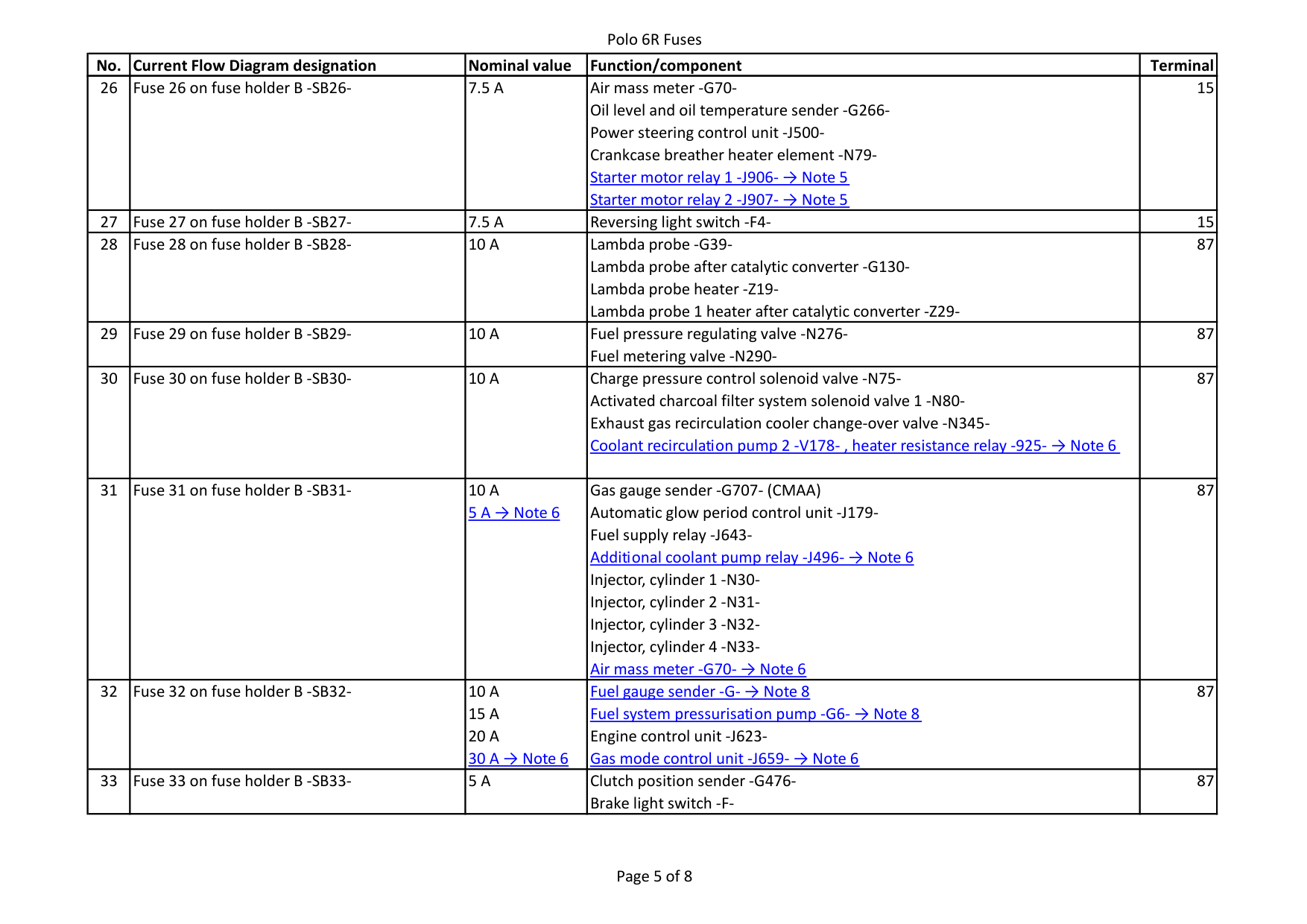
|29|Fuse 29 on fuse holder B -SB29-|10 A|Fuel pressure regulating valve -N276Fuel metering valve -N290-|87| |30|Fuse 30 on fuse holder B -SB30-|10 A|Charge pressure control solenoid valve -N75Activated charcoal filter system solenoid valve 1 -N80Exhaust gas recirculation cooler change-over valve -N345Coolant recirculation pump 2 -V178- , heater resistance relay -925- → Note 6
|87| |31|Fuse 31 on fuse holder B -SB31-|10 A 5 A → Note 6
|Gas gauge sender -G707- (CMAA) Automatic glow period control unit -J179Fuel supply relay -J643Additional coolant pump relay -J496- → Note 6
Injector, cylinder 1 -N30-
Injector, cylinder 2 -N31-
Injector, cylinder 3 -N32-
Injector, cylinder 4 -N33Air mass meter -G70- → Note 6
|87| |32|Fuse 32 on fuse holder B -SB32-|10 A 15 A 20 A 30 A → Note 6
|Engine control unit -J623Gas mode control unit -J659- → Note 6
Fuel gauge sender -G- → Note 8 Fuel system pressurisation pump -G6- → Note 8
|87| |33|Fuse 33 on fuse holder B -SB33-|5 A|Clutch position sender -G476Brake light switch -F-|87|
|No.|Current Flow Diagram designation|Nominal value|Function/component|Terminal| |---|---|---|---|---| |34|Fuse 34 on fuse holder B -SB34-|15 A 7.5 A → Note 6
|Control unit in dash panel insert -J285Left headlight main beam bulb -M30Right main beam bulb -M32- , onboard supply control unit -J519- (T73a/62) → Note 10 Left gas discharge bulb control unit -J343- → Note 6 Right gas discharge control unit -J344- → Note 6
|??| |35|Fuse 35 on fuse holder B -SB35-|15 A 20 A → Note 6
|Engine control unit -J623Fuel supply relay -J643-|87| |36|Fuse 36 on fuse holder B -SB36-|7.5 A|Right headlight main beam bulb -M32-|87| |37|Fuse 37 on fuse holder B -SB37-|25 A|Heated driver seat regulator -E94Heated front passenger seat regulator -E95Heated front seats control unit -J774-|75| |38|Fuse 38 on fuse holder B -SB38-|30 A|Mechatronic unit for dual clutch gearbox -J743-|30|
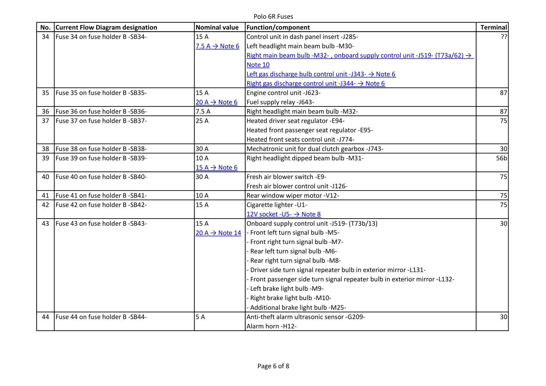
|39|Fuse 39 on fuse holder B -SB39-|10 A 15 A → Note 6
|Right headlight dipped beam bulb -M31-|56b| |40|Fuse 40 on fuse holder B -SB40-|30 A|Fresh air blower switch -E9Fresh air blower control unit -J126-|75| |41|Fuse 41 on fuse holder B -SB41-|10 A|Rear window wiper motor -V12-|75| |42|Fuse 42 on fuse holder B -SB42-|15 A|Cigarette lighter -U112V socket -U5- → Note 8
|75| |43|Fuse 43 on fuse holder B -SB43-|15 A 20 A → Note 14
|- Right brake light bulb -M10-
- Additional brake light bulb -M25-
Onboard supply control unit -J519- (T73b/13)
- Front left turn signal bulb -M5-
- Front right turn signal bulb -M7-
- Rear left turn signal bulb -M6-
- Rear right turn signal bulb -M8-
- Driver side turn signal repeater bulb in exterior mirror -L131-
- Front passenger side turn signal repeater bulb in exterior mirror -L132-
- Left brake light bulb -M9-
|30| |44|Fuse 44 on fuse holder B -SB44-|5 A|Anti-theft alarm ultrasonic sensor -G209Alarm horn -H12-|30|
|No.|Current Flow Diagram designation|Nominal value|Function/component|Terminal| |---|---|---|---|---| |45|Fuse 45 on fuse holder B -SB45-|15 A 20 A → Note 6
|Control unit with display for radio and navigation -J503Multimedia system control unit -J650Radio -RVoltage stabiliser -J532- → Note 5
|30| |46|Fuse 46 on fuse holder B -SB46-|20 A|- Treble tone horn -H2-
- Bass tone horn -H7-
Headlight washer system relay -J39Onboard supply control unit -J519- (T73a/73)|30| |47|Fuse 47 on fuse holder B -SB47-|20 A|- Wiper motor -V-
Onboard supply control unit -J519- (T73a/68)|30| |48|Fuse 48 on fuse holder B -SB48-|25 A|- Driver side central locking lock unit -F220-
- Front passenger side central locking lock unit -F221-
- Rear left central locking lock unit -F222-
- Rear right central locking lock unit -F223-
Onboard supply control unit -J519- (T73a/16)
- Rear lid lock unit -F256-
- Tank filler flap locking motor -V155-
|30|
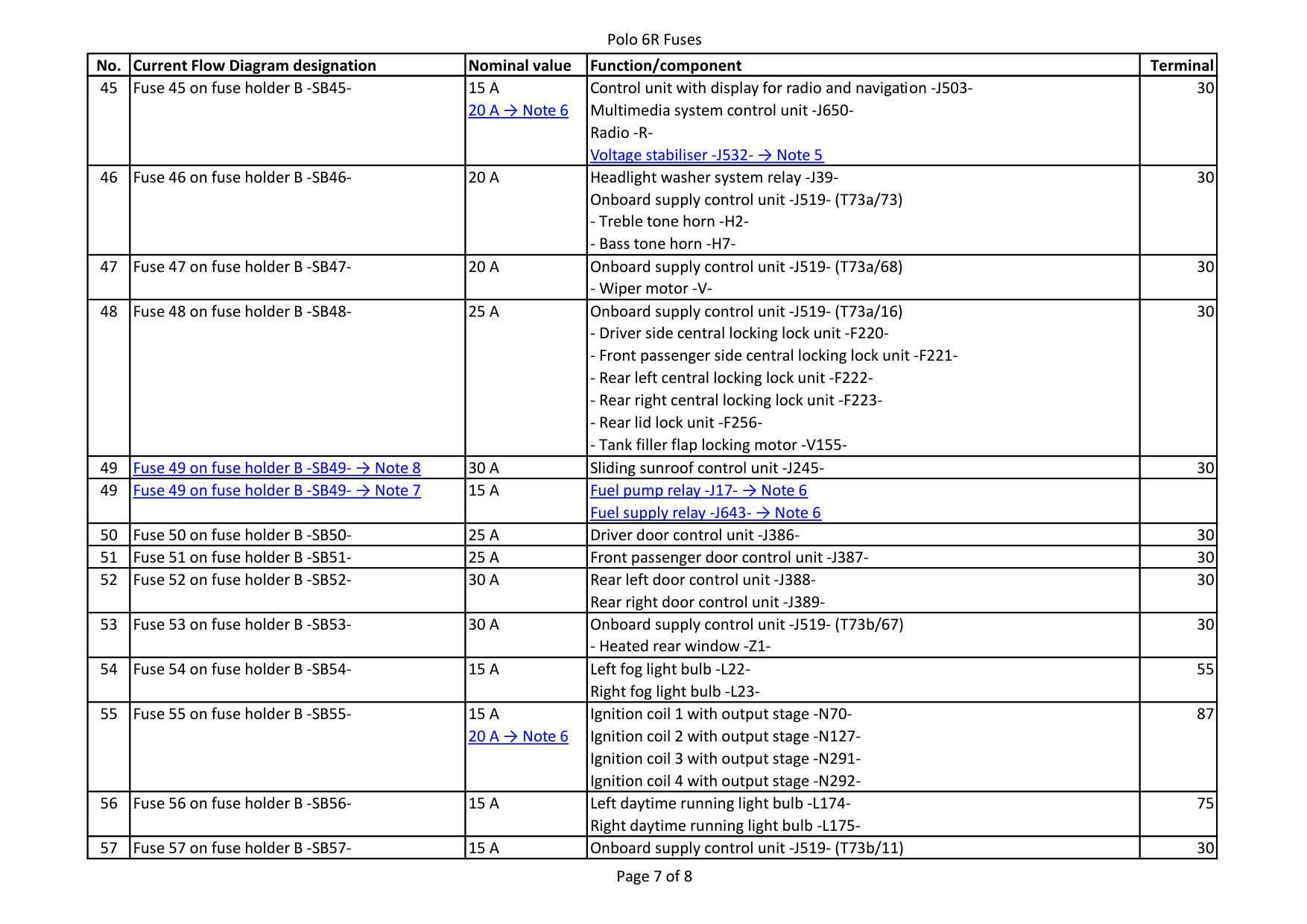
|49|Fuse 49 on fuse holder B -SB49- → Note 8
|30 A|Sliding sunroof control unit -J245-|30| |49|Fuse 49 on fuse holder B -SB49- → Note 7
|15 A|Fuel pump relay -J17- → Note 6 Fuel supply relay -J643- → Note 6
| | |50|Fuse 50 on fuse holder B -SB50-|25 A|Driver door control unit -J386-|30| |51|Fuse 51 on fuse holder B -SB51-|25 A|Front passenger door control unit -J387-|30| |52|Fuse 52 on fuse holder B -SB52-|30 A|Rear left door control unit -J388Rear right door control unit -J389-|30| |53|Fuse 53 on fuse holder B -SB53-|30 A|Onboard supply control unit -J519- (T73b/67)
- Heated rear window -Z1-|30| |54|Fuse 54 on fuse holder B -SB54-|15 A|Left fog light bulb -L22Right fog light bulb -L23-|55| |55|Fuse 55 on fuse holder B -SB55-|15 A 20 A → Note 6
|Ignition coil 1 with output stage -N70-
Ignition coil 2 with output stage -N127-
Ignition coil 3 with output stage -N291-
Ignition coil 4 with output stage -N292-
|87| |56|Fuse 56 on fuse holder B -SB56-|15 A|Left daytime running light bulb -L174Right daytime running light bulb -L175-|75| |57|Fuse 57 on fuse holder B -SB57-|15 A|Onboard supply control unit -J519- (T73b/11)|30|
|No.|Current Flow Diagram designation|Nominal value|Function/component|Terminal| |---|---|---|---|---|
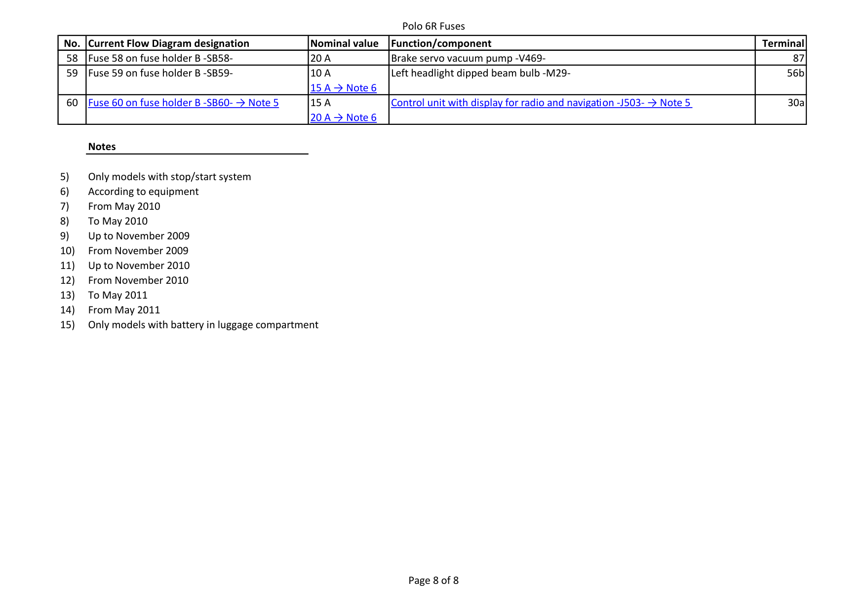
|58|Fuse 58 on fuse holder B -SB58-|20 A|Brake servo vacuum pump -V469-|87| |59|Fuse 59 on fuse holder B -SB59-|10 A 15 A → Note 6
|Left headlight dipped beam bulb -M29-|56b| |60|Fuse 60 on fuse holder B -SB60- → Note 5
|15 A 20 A → Note 6
|Control unit with display for radio and navigation -J503- → Note 5
|30a|