
Ask AI
— answers from the official manualAnswers from the official manual.
Common questions
Common Questions
9 totalWhat is the correct way to tighten cables on my Weider 9940 if they have become loose?
Refer to MAINTENANCE on page 39 of your manual for cable tightening instructions. Slack can be removed by adjusting pulleys or reattaching them closer to the center of the Pulley Plates (70) and ensuring cables move freely without touching any parts.
How do I safely lock the weight stack before storage?
Attach the Lock Pin (39) through one of the Weight Guides (31), then secure the Lock (38) into the Lock Pin to prevent unauthorized use and for safe storage, as explained in LOCKING THE WEIGHT STACK on page 36.
What is the assembly sequence for attaching cables to the Weider 9940?
Follow detailed instructions starting from ASSEMBLY on page 7 up to MAINTENANCE and ensure proper routing as per CABLE DIAGRAM on page 38. This includes steps such as identifying burn cable, pulleys, and mounting points.
How often should I inspect the Weider 9940 for worn parts?
According to IMPORTANT PRECAUTIONS on page 3, owner is responsible to inspect and properly tighten all parts regularly and replace any worn part immediately.
What precautions should be taken before setting up the Weider 9900?
Ensure adequate clearance space for assembly and usage, place it indoors in a level position on a mat or floor surface as specified on page 4.
How does one adjust seat height on the Weider 9900?
Remove the Adjustment Knob (29), move the Seat (24) to your desired position, and tighten the Adjustment Knob into the Seat Tube (8) in any of the holes as shown under ADJUSTING THE SEAT on page 35.
Full Manual
48 pages
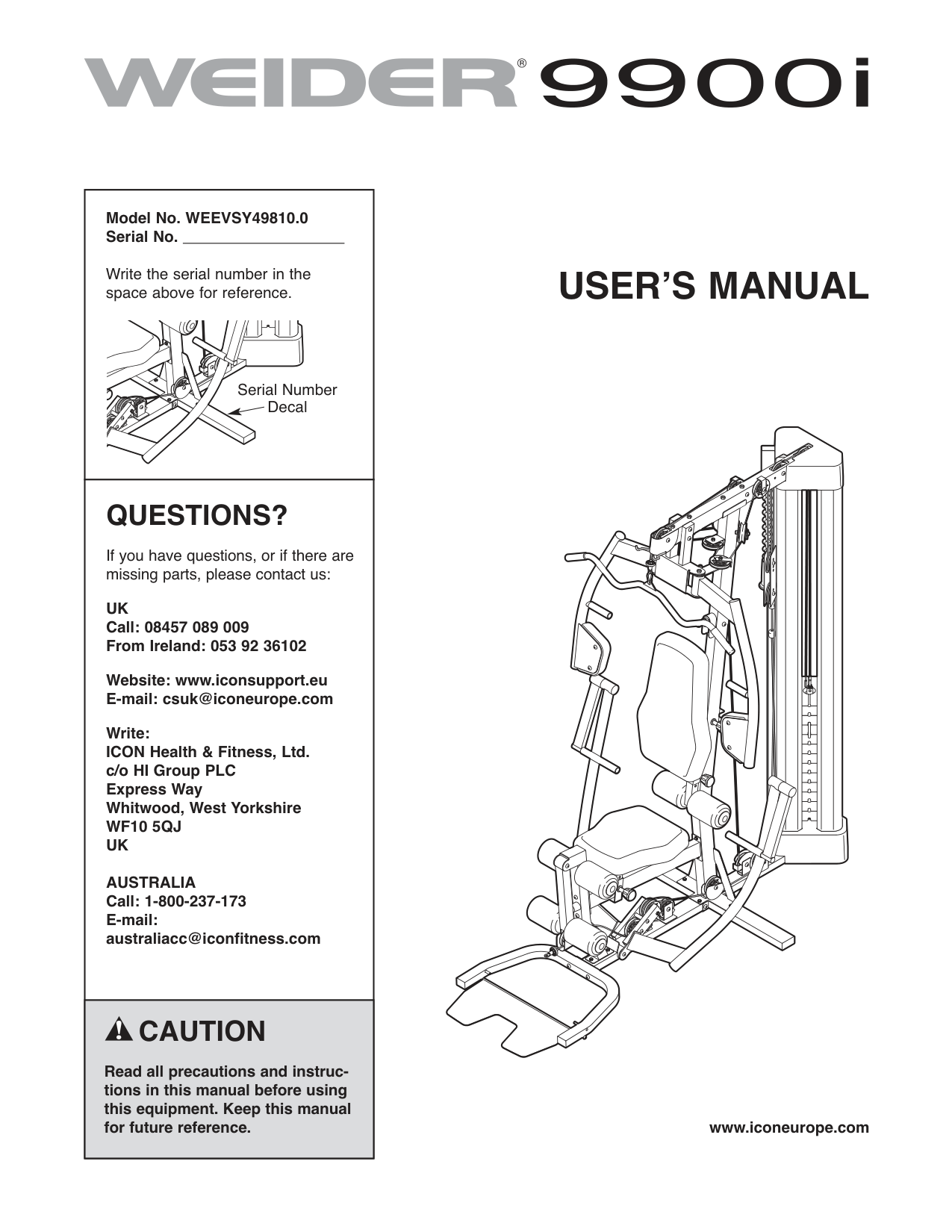
Model No. WEEVSY49810.0 Serial No.
Write the serial number in the space above for reference.
Serial Number Decal
QUESTIONS?
If you have questions, or if there are missing parts, please contact us:
UK Call: 08457 089 009 From Ireland: 053 92 36102
Website: www.iconsupport.eu E-mail: [email protected]
Write: ICON Health & Fitness, Ltd. c/o HI Group PLC Express Way Whitwood, West Yorkshire WF10 5QJ UK
AUSTRALIA Call: 1-800-237-173 E-mail: [email protected]
CAUTION
Read all precautions and instructions in this manual before using this equipment. Keep this manual for future reference.
USERʼS MANUAL
| | | |---|---| | | |
www.iconeurope.com
TABLE OF CONTENTS
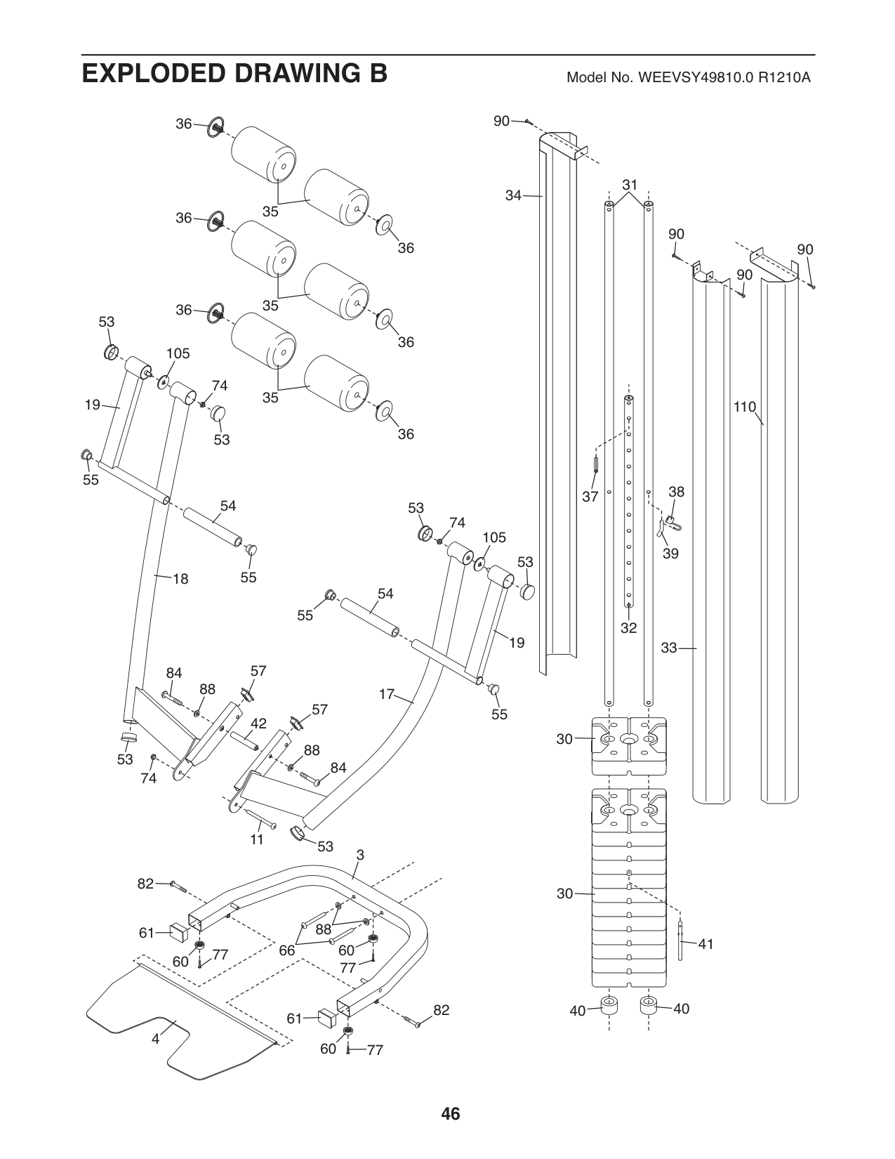
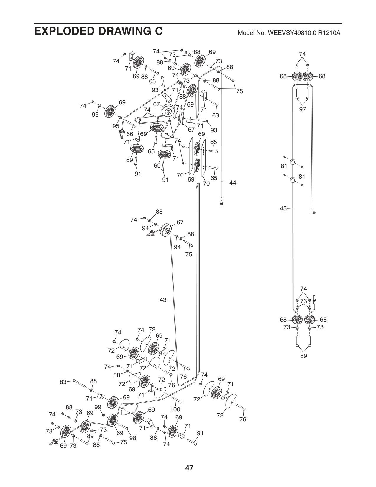
WARNING DECAL PLACEMENT . . . . . . . . . . . . . . . . . . . . . . . . . . . . . . . . . . . . . . . . . . . . . . . . . . . . . . . . . . . . . .2 IMPORTANT PRECAUTIONS . . . . . . . . . . . . . . . . . . . . . . . . . . . . . . . . . . . . . . . . . . . . . . . . . . . . . . . . . . . . . . . .3 BEFORE YOU BEGIN . . . . . . . . . . . . . . . . . . . . . . . . . . . . . . . . . . . . . . . . . . . . . . . . . . . . . . . . . . . . . . . . . . . . . .4 PART IDENTIFICATION CHART . . . . . . . . . . . . . . . . . . . . . . . . . . . . . . . . . . . . . . . . . . . . . . . . . . . . . . . . . . . . . .5 ASSEMBLY . . . . . . . . . . . . . . . . . . . . . . . . . . . . . . . . . . . . . . . . . . . . . . . . . . . . . . . . . . . . . . . . . . . . . . . . . . . . . . .7 ADJUSTMENT . . . . . . . . . . . . . . . . . . . . . . . . . . . . . . . . . . . . . . . . . . . . . . . . . . . . . . . . . . . . . . . . . . . . . . . . . . .34 WEIGHT RESISTANCE CHART . . . . . . . . . . . . . . . . . . . . . . . . . . . . . . . . . . . . . . . . . . . . . . . . . . . . . . . . . . . . . .37 CABLE DIAGRAM . . . . . . . . . . . . . . . . . . . . . . . . . . . . . . . . . . . . . . . . . . . . . . . . . . . . . . . . . . . . . . . . . . . . . . . . .38 MAINTENANCE . . . . . . . . . . . . . . . . . . . . . . . . . . . . . . . . . . . . . . . . . . . . . . . . . . . . . . . . . . . . . . . . . . . . . . . . . .39 EXERCISE GUIDELINES . . . . . . . . . . . . . . . . . . . . . . . . . . . . . . . . . . . . . . . . . . . . . . . . . . . . . . . . . . . . . . . . . . .40 PART LIST . . . . . . . . . . . . . . . . . . . . . . . . . . . . . . . . . . . . . . . . . . . . . . . . . . . . . . . . . . . . . . . . . . . . . . . . . . . . . .43 EXPLODED DRAWING . . . . . . . . . . . . . . . . . . . . . . . . . . . . . . . . . . . . . . . . . . . . . . . . . . . . . . . . . . . . . . . . . . . .45 ORDERING REPLACEMENT PARTS . . . . . . . . . . . . . . . . . . . . . . . . . . . . . . . . . . . . . . . . . . . . . . . . . .Back Cover
WARNING DECAL PLACEMENT
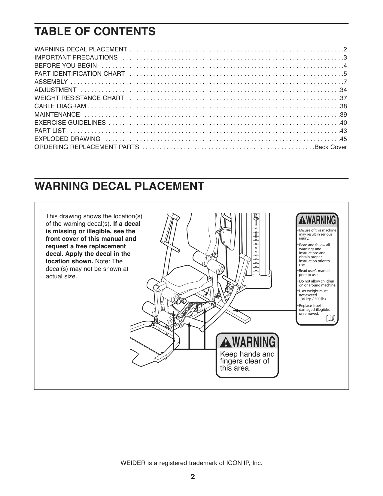
This drawing shows the location(s) of the warning decal(s). If a decal is missing or illegible, see the front cover of this manual and request a free replacement decal. Apply the decal in the location shown. Note: The decal(s) may not be shown at actual size.
WEIDER is a registered trademark of ICON IP, Inc.
IMPORTANT PRECAUTIONS
WARNING:Toreducetheriskofseriousinjury,readallimportantprecautionsand instructions in this manual and all warnings on your weight system before using your weight system. ICON assumes no responsibility for personal injury or property damage sustained by or through the use of this product.
BEFORE YOU BEGIN
Thank you for selecting the versatile WEIDER
9900 I weight system. The weight system offers a selection of weight stations designed to develop every major muscle group of the body. Whether your goal is to tone your body, build dramatic muscle size and strength, or improve your cardiovascular system, the weight system will help you to achieve the specific results you want.
®
For your benefit, read this manual carefully before using the weight system. If you have questions after
reading this manual, please see the front cover of this manual. To help us assist you, note the product model number and serial number before contacting us. The model number and the location of the serial number decal are shown on the front cover of this manual.
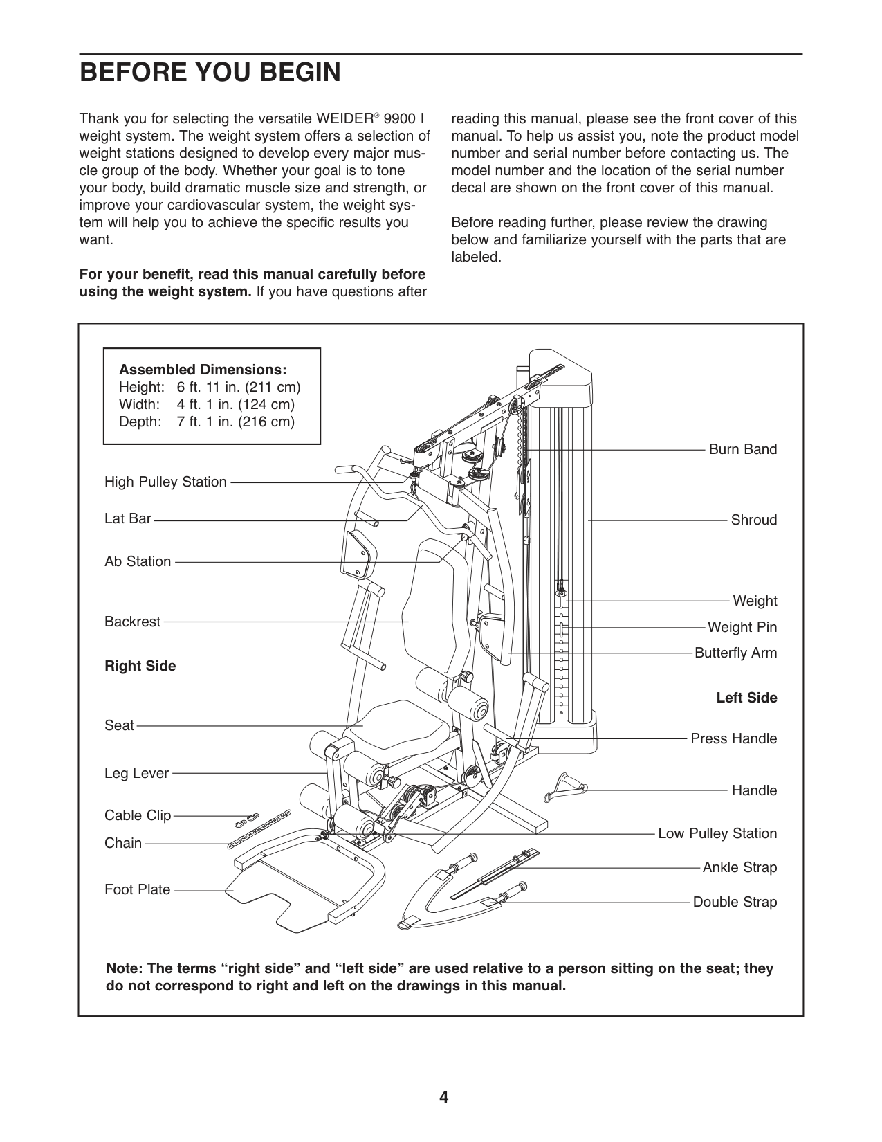
Before reading further, please review the drawing below and familiarize yourself with the parts that are labeled.
||Assembled Dimensions: Height: 6 ft. 11 in. (211 cm) Width: 4 ft. 1 in. (124 cm) Depth: 7 ft. 1 in. (216 cm)| |---|
Shroud
High Pulley Station
Low Pulley Station Ankle Strap Double Strap
Right Side
Left Side
Backrest
Ab Station
Lat Bar
Weight Weight Pin
Leg Lever
Cable Clip Chain
Foot Plate
Seat
Butterfly Arm
Burn Band
Press Handle
Handle
Note: The terms “right side” and “left side” are used relative to a person sitting on the seat; they do not correspond to right and left on the drawings in this manual.| |---|
PART IDENTIFICATION CHART
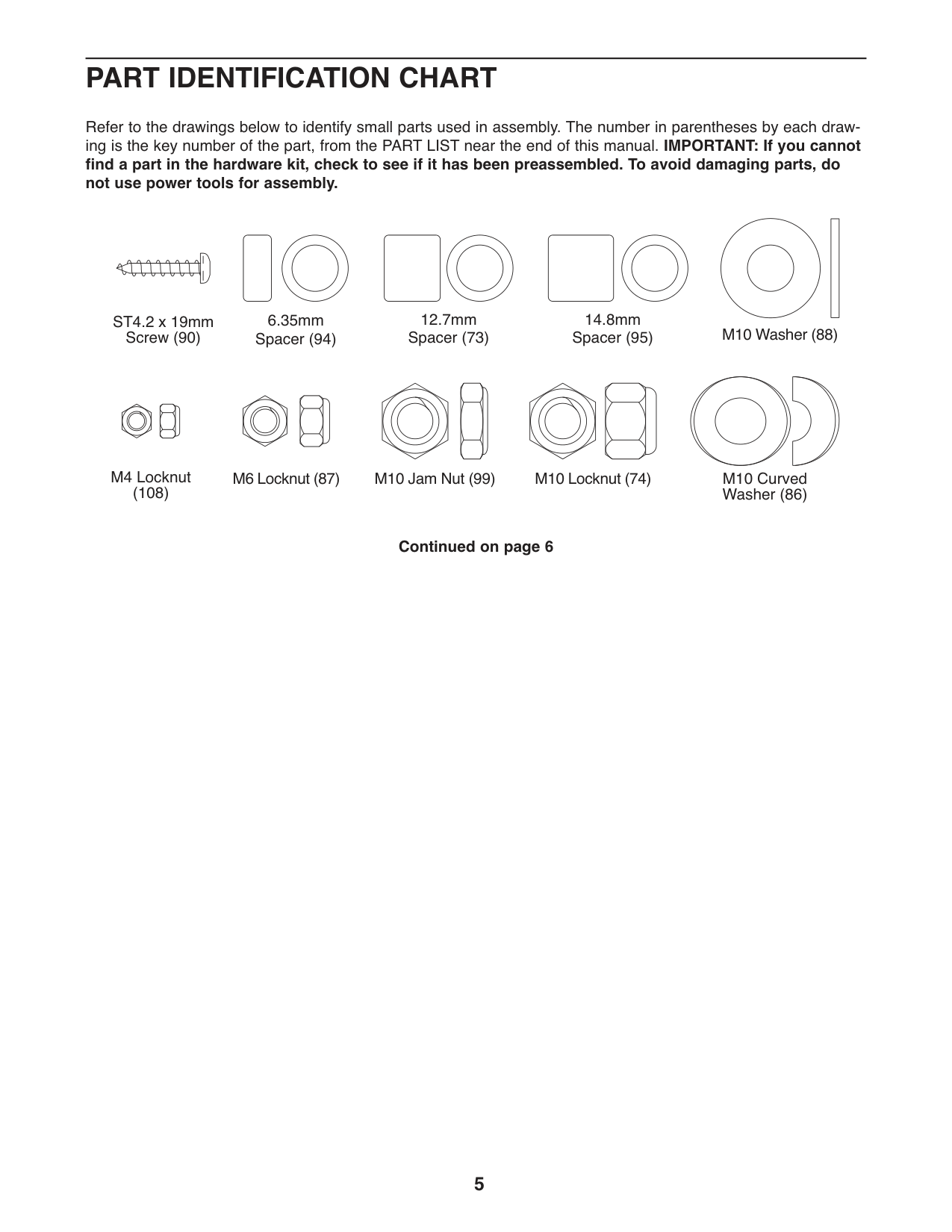
Refer to the drawings below to identify small parts used in assembly. The number in parentheses by each drawing is the key number of the part, from the PART LIST near the end of this manual. IMPORTANT:If you cannot find a part in the hardware kit, check to see if it has been preassembled. To avoid damaging parts, do not use power tools for assembly.
| | | |---|---|
| | | | | |
12.7mm Spacer (73)
14.8mm Spacer (95)
6.35mm Spacer (94)
ST4.2 x 19mm Screw (90)
M10 Washer (88)
M4 Locknut (108)
M10 Jam Nut (99)M6Locknut(87)
M10 Locknut (74)
M10 Curved Washer (86)
#### Continued on page 6
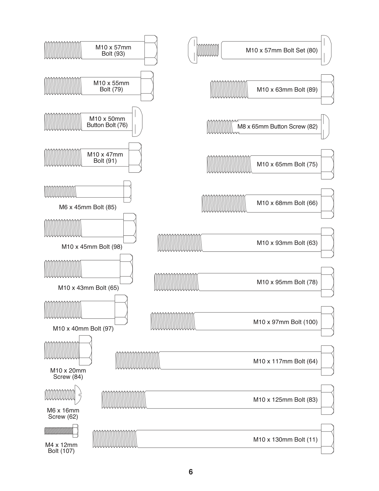
M10 x 57mm Bolt (93)
| | | |---|---| |M10 x 57mm Bolt Set (80)| | | | |
M10 x 55mm Bolt (79)
M10 x 63mm Bolt (89)
M10 x 50mm Button Bolt (76) M8 x 65mm Button Screw (82)
M10 x 47mm Bolt (91)
M10 x 65mm Bolt (75)
M10 x 68mm Bolt (66)
M6 x 45mm Bolt (85)
M10 x 93mm Bolt (63) M10 x 45mm Bolt (98)
M10 x 95mm Bolt (78)
M10 x 43mm Bolt (65)
M10 x 97mm Bolt (100)
M10 x 40mm Bolt (97)
M10 x 117mm Bolt (64)
M10 x 20mm Screw (84)
M10 x 125mm Bolt (83)
M6 x 16mm Screw (62)
M10 x 130mm Bolt (11)
M4 x 12mm Bolt (107)
ASSEMBLY
|To make assembly easier, carefully read the following information and instructions:
• Assembly requires two persons.
• Because of its weight and size, assemble the weight system in the location where it will be used. Make sure that there is enough clearance to walk around the weight system.
• Place all parts in a cleared area and remove the packing materials. Do not dispose of the packing materials until assembly is completed.
• For help identifying small parts, use the PART IDENTIFICATION CHART on pages 5 and 6.
• The following tools (not included) may be required for assembly: two adjustable wrenches one rubber mallet one standard screwdriver one Phillips screwdriver Assembly may be more convenient if you have a socket set, a set of open-end or closed-end wrenches, or a set of ratchet wrenches.| |---|
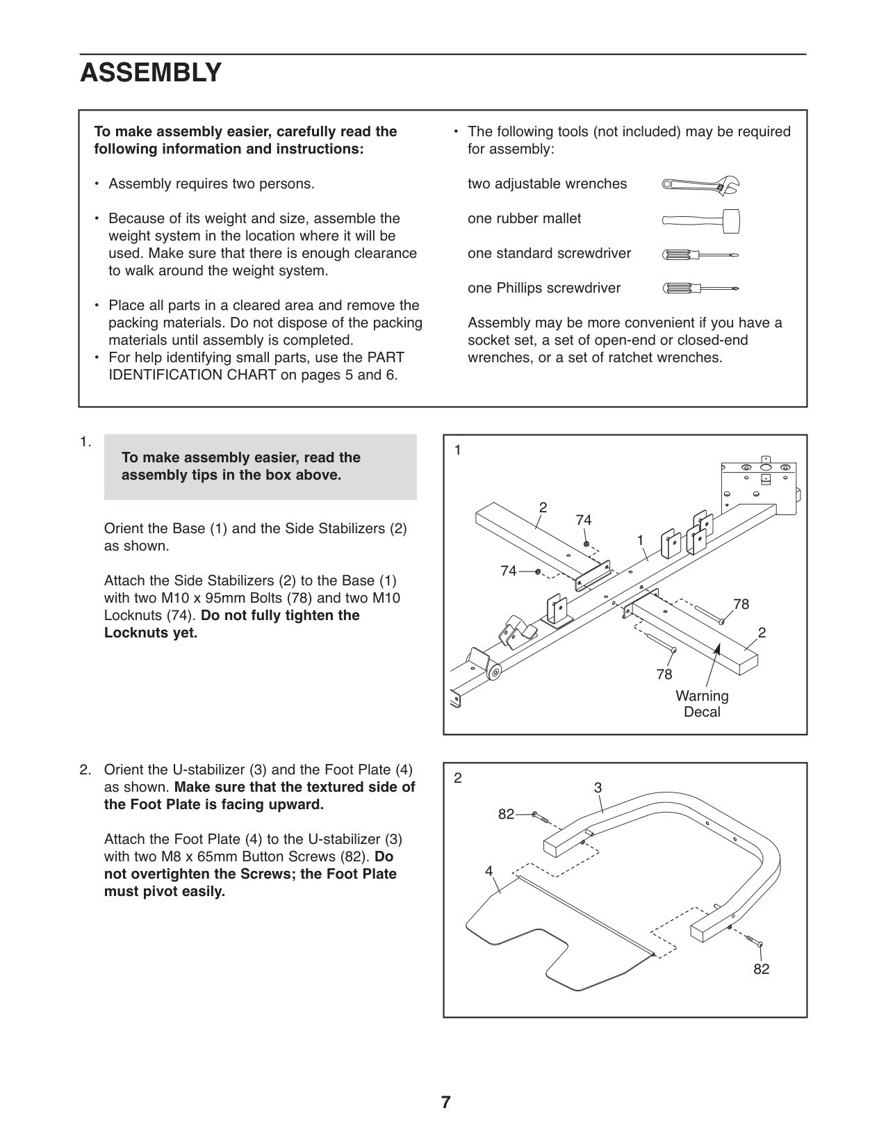
Orient the Base (1) and the Side Stabilizers (2) as shown.
Attach the Side Stabilizers (2) to the Base (1) with two M10 x 95mm Bolts (78) and two M10 Locknuts (74). Do not fully tighten the Locknuts yet.
|1
1
2
78
78
74
74
Warning Decal
2| |---|
To make assembly easier, read the assembly tips in the box above.
Attach the Foot Plate (4) to the U-stabilizer (3) with two M8 x 65mm Button Screws (82). Do not overtighten the Screws; the Foot Plate must pivot easily.
|2
82
82
3
4
|
|---|
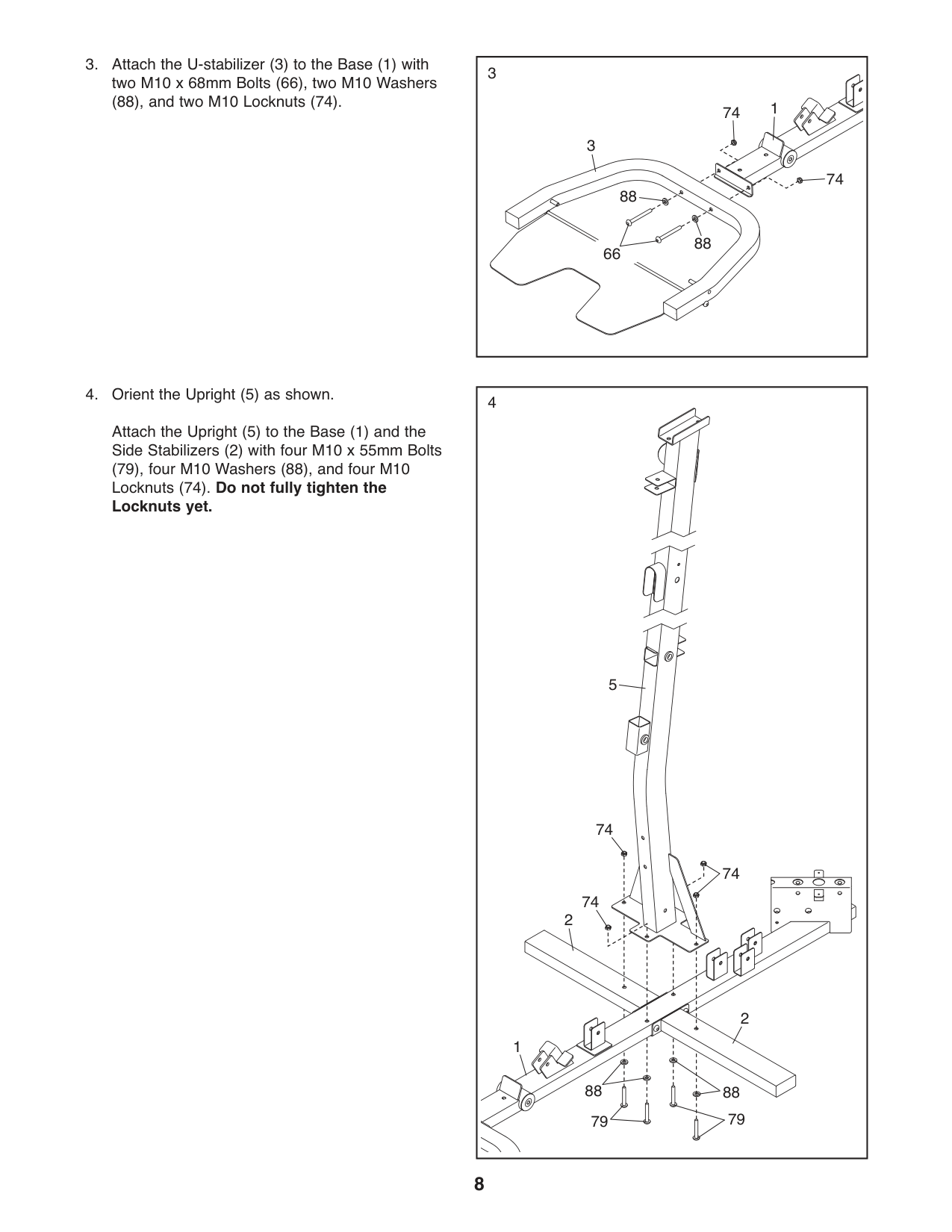
(88), and two M10 Locknuts (74).
|3
88
88
3
74
74
1
66
| |---|
|4
74
5
74
74
1
2
2
79 79
8888
| |---|
Attach the Upright (5) to the Base (1) and the Side Stabilizers (2) with four M10 x 55mm Bolts
(79), four M10 Washers (88), and four M10 Locknuts (74). Do not fully tighten the Locknuts yet.
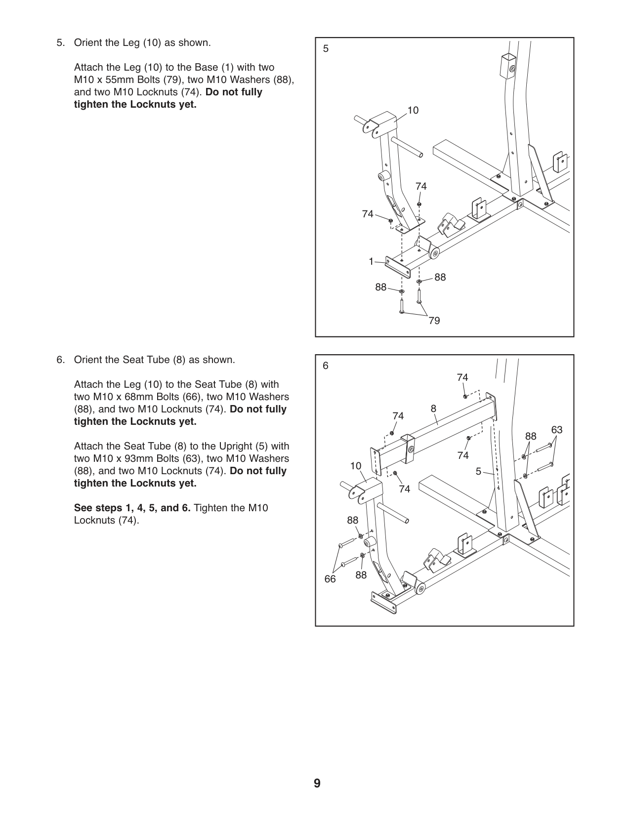
Attach the Leg (10) to the Base (1) with two M10 x 55mm Bolts (79), two M10 Washers (88), and two M10 Locknuts (74). Do not fully tighten the Locknuts yet.
|5
74
10
88
88
79
1
74| |---|
|6
8
5
74
63 88
74
10
74
74
88
8866
| |---|
Attach the Leg (10) to the Seat Tube (8) with two M10 x 68mm Bolts (66), two M10 Washers
#### (88), and two M10 Locknuts (74). Do not fully tighten the Locknuts yet.
Attach the Seat Tube (8) to the Upright (5) with two M10 x 93mm Bolts (63), two M10 Washers (88), and two M10 Locknuts (74). Do not fully
tighten the Locknuts yet. See steps 1, 4, 5, and 6. Tighten the M10 Locknuts (74).
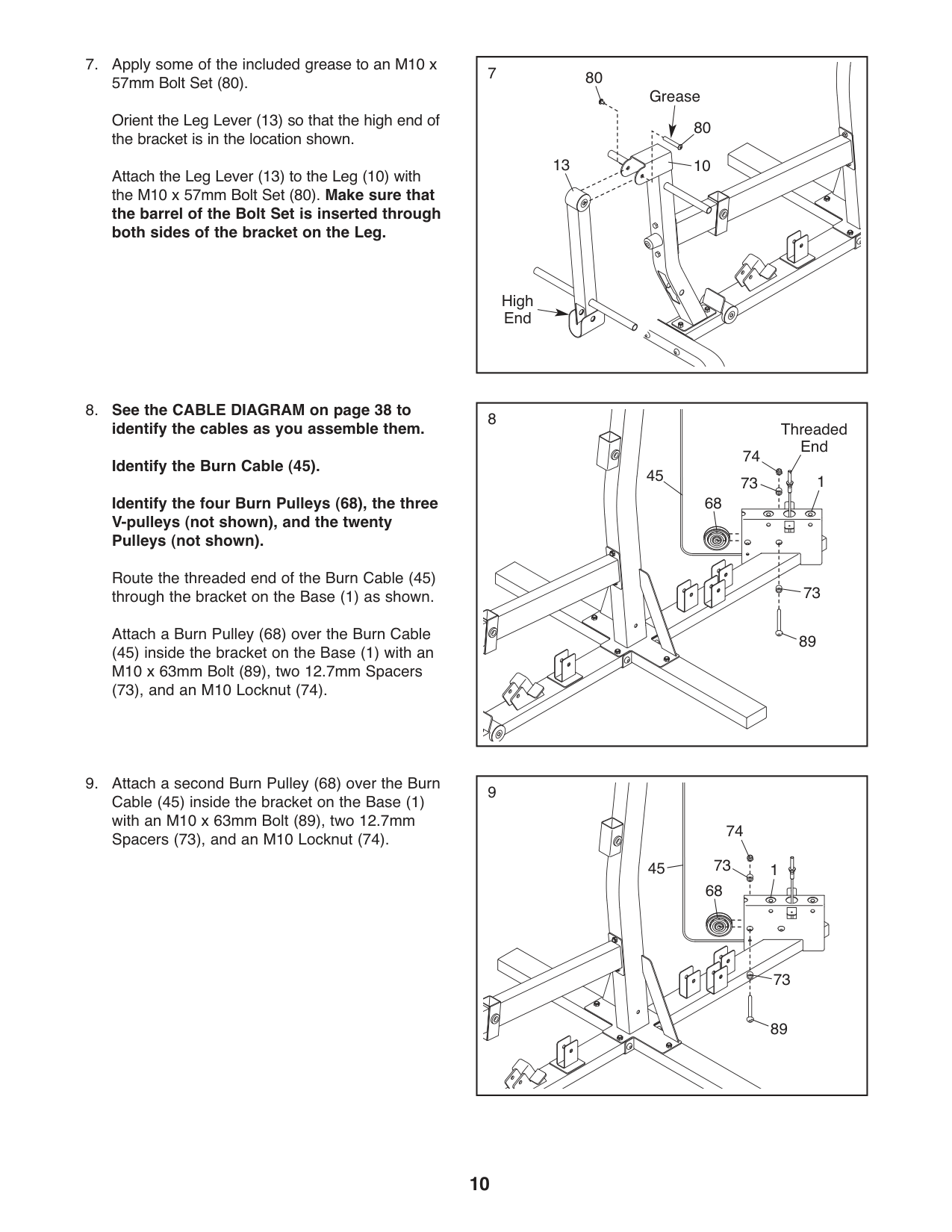
Orient the Leg Lever (13) so that the high end of the bracket is in the location shown.
Attach the Leg Lever (13) to the Leg (10) with the M10 x 57mm Bolt Set (80). Make sure that the barrel of the Bolt Set is inserted through both sides of the bracket on the Leg.
13
80 10
Grease
High End
| | | |---|---| | | |
Identify the four Burn Pulleys (68), the three V-pulleys (not shown), and the twenty Pulleys (not shown).
Route the threaded end of the Burn Cable (45) through the bracket on the Base (1) as shown.
Attach a Burn Pulley (68) over the Burn Cable (45) inside the bracket on the Base (1) with an M10 x 63mm Bolt (89), two 12.7mm Spacers
(73), and an M10 Locknut (74).
89
73
Threaded End
1 68
45
9
45
1 68
73
89
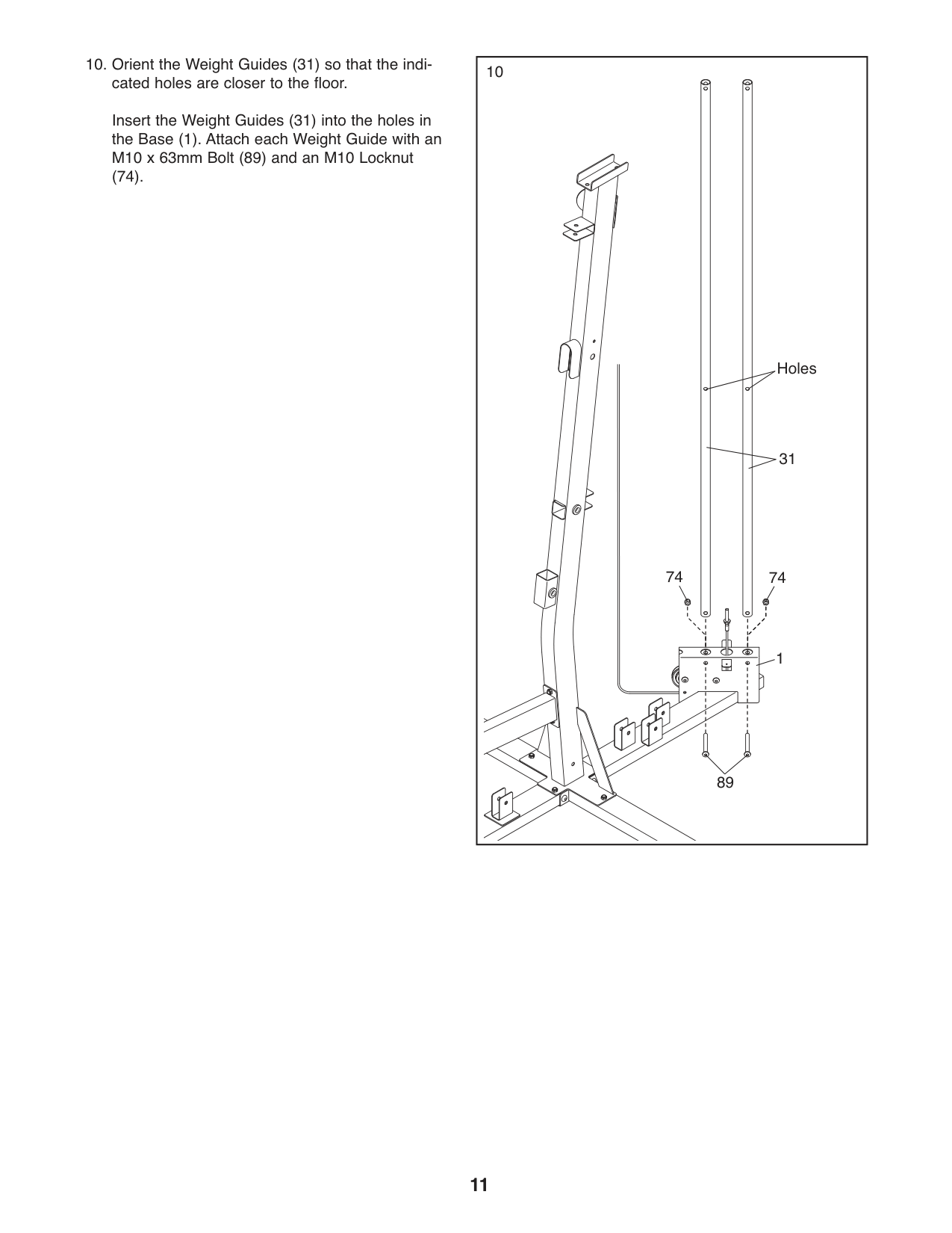
Insert the Weight Guides (31) into the holes in the Base (1). Attach each Weight Guide with an M10 x 63mm Bolt (89) and an M10 Locknut
(74).
|10
31
Holes
89
7474
1
| |---|
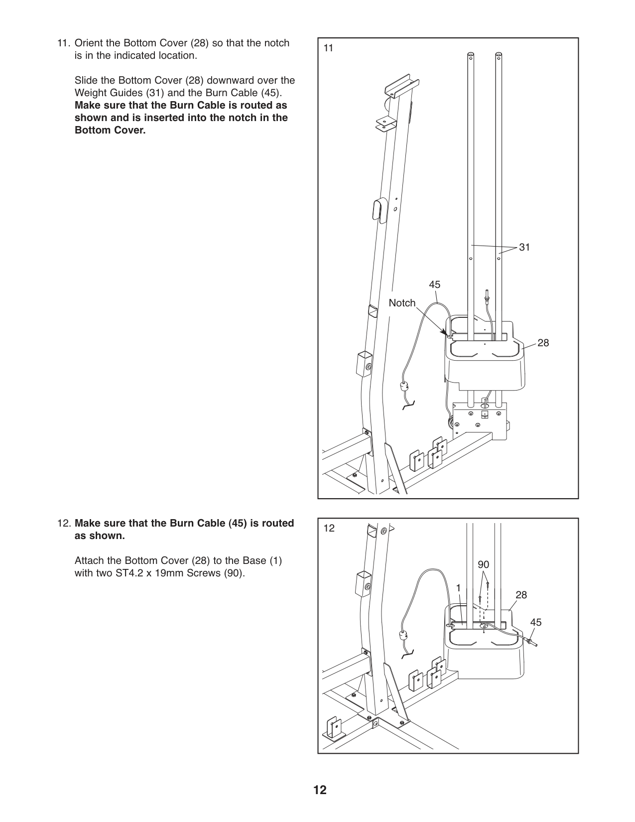
1111.OrienttheBottomCover(28)sothatthenotch is in the indicated location. Slide the Bottom Cover (28) downward over the Weight Guides (31) and the Burn Cable (45).
Make sure that the Burn Cable is routed as shown and is inserted into the notch in the Bottom Cover.
31
45
Notch
28
#### 12. Make sure that the Burn Cable (45) is routedas shown.
Attach the Bottom Cover (28) to the Base (1) with two ST4.2 x 19mm Screws (90).
12
90
1
28
45
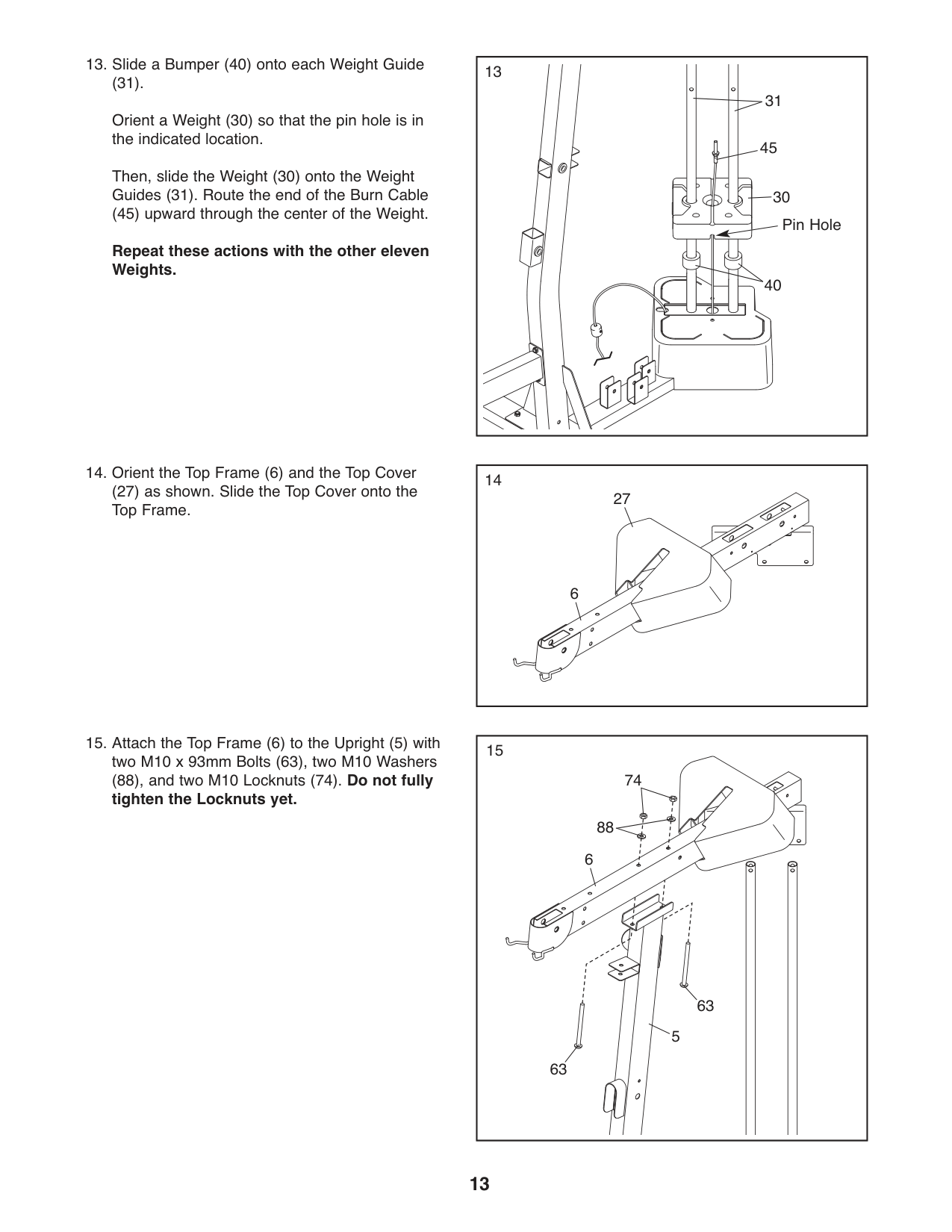
(31). Orient a Weight (30) so that the pin hole is in the indicated location. Then, slide the Weight (30) onto the Weight Guides (31). Route the end of the Burn Cable (45) upward through the center of the Weight.
Repeat these actions with the other eleven Weights.
13
31
30 Pin Hole
40
45
|14
27
6| |---|
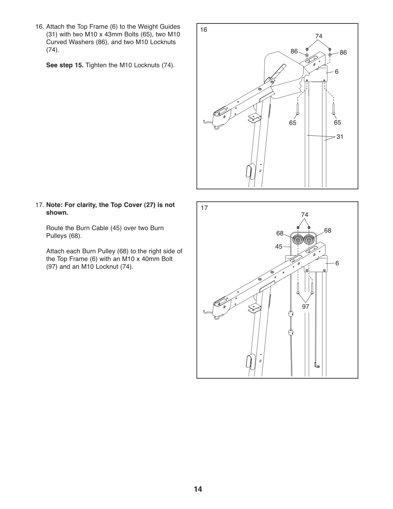
(27) as shown. Slide the Top Cover onto the Top Frame.
(88), and two M10 Locknuts (74). Do not fully tighten the Locknuts yet.
15
74
88
6
63
5
63
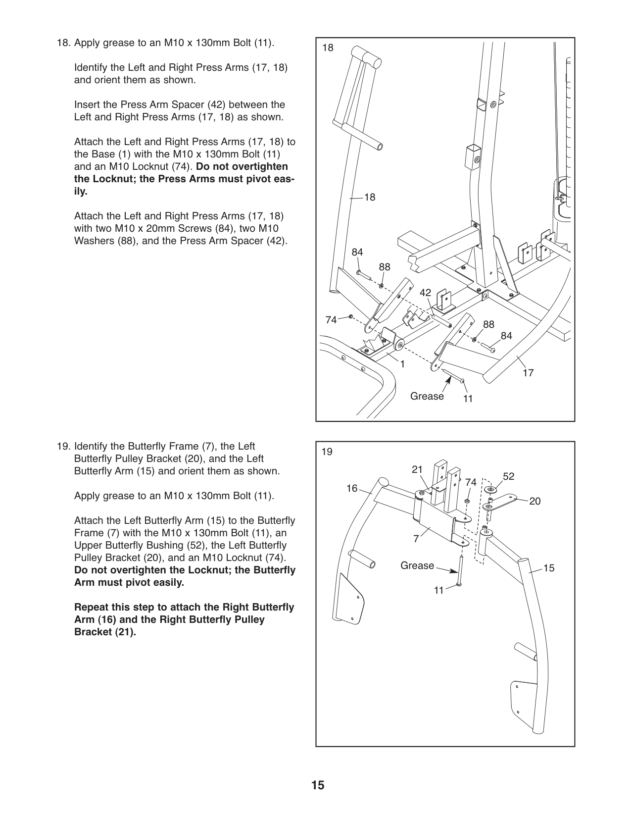
(31) with two M10 x 43mm Bolts (65), two M10 Curved Washers (86), and two M10 Locknuts
(74). See step 15. Tighten the M10 Locknuts (74).
16
74
65 65
86 86
31
6
Route the Burn Cable (45) over two Burn Pulleys (68).
Attach each Burn Pulley (68) to the right side of the Top Frame (6) with an M10 x 40mm Bolt
(97) and an M10 Locknut (74).
17
74
68 68
| | | | |---|---|---| | | | |
45
6
97
Identify the Left and Right Press Arms (17, 18) and orient them as shown.
Insert the Press Arm Spacer (42) between the Left and Right Press Arms (17, 18) as shown.
Attach the Left and Right Press Arms (17, 18) to the Base (1) with the M10 x 130mm Bolt (11) and an M10 Locknut (74). Do not overtighten the Locknut; the Press Arms must pivot easily.
Attach the Left and Right Press Arms (17, 18) with two M10 x 20mm Screws (84), two M10 Washers (88), and the Press Arm Spacer (42).
Attach the Left Butterfly Arm (15) to the Butterfly Frame (7) with the M10 x 130mm Bolt (11), an Upper Butterfly Bushing (52), the Left Butterfly Pulley Bracket (20), and an M10 Locknut (74). Do not overtighten the Locknut; the Butterfly Arm must pivot easily.
Repeat this step to attach the Right Butterfly Arm (16) and the Right Butterfly Pulley Bracket (21).
18
18
84
88
42
74 88
84
1
17
11Grease
|19
15
20
21
52 74
11
7
16
Grease| |---|
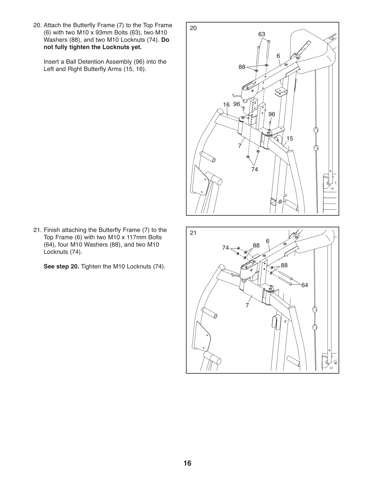
(6) with two M10 x 93mm Bolts (63), two M10 Washers (88), and two M10 Locknuts (74). Do not fully tighten the Locknuts yet.
Insert a Ball Detention Assembly (96) into the Left and Right Butterfly Arms (15, 16).
20
(64), four M10 Washers (88), and two M10 Locknuts (74).
See step 20. Tighten the M10 Locknuts (74).
63
6
88
9616
96
15
7
74
21
6
74 88
88
64
7
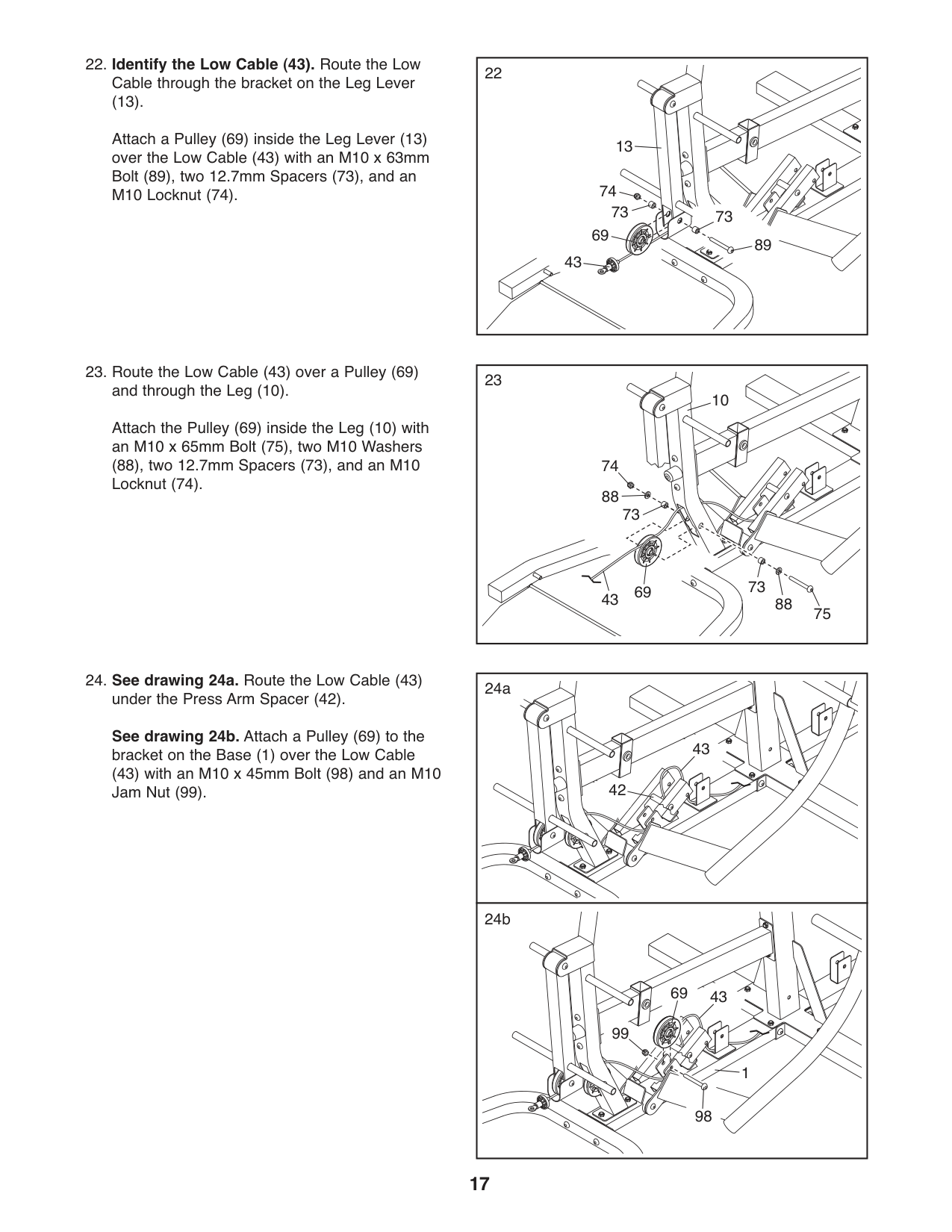
(13).
Attach a Pulley (69) inside the Leg Lever (13) over the Low Cable (43) with an M10 x 63mm Bolt (89), two 12.7mm Spacers (73), and an M10 Locknut (74).
Attach the Pulley (69) inside the Leg (10) with an M10 x 65mm Bolt (75), two M10 Washers (88), two 12.7mm Spacers (73), and an M10 Locknut (74).
|22
13
74
73 69
43
73
89| |---|
|23
6943
10
74
73
73
75
88
88| |---|
|42
43
24a| |---| |24b
1
4369
98
99
|
See drawing 24b. Attach a Pulley (69) to the bracket on the Base (1) over the Low Cable
(43) with an M10 x 45mm Bolt (98) and an M10 Jam Nut (99).
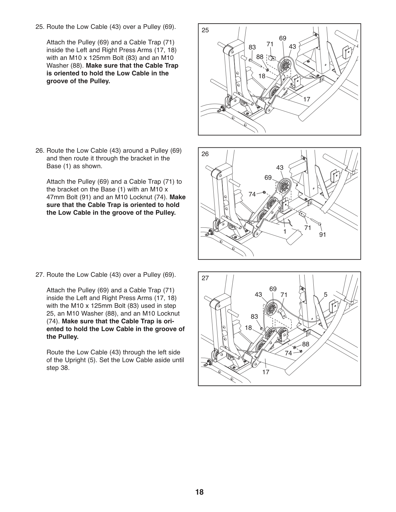
Attach the Pulley (69) and a Cable Trap (71) to the bracket on the Base (1) with an M10 x 47mm Bolt (91) and an M10 Locknut (74). Make sure that the Cable Trap is oriented to hold the Low Cable in the groove of the Pulley.
Attach the Pulley (69) and a Cable Trap (71) inside the Left and Right Press Arms (17, 18) with an M10 x 125mm Bolt (83) and an M10 Washer (88). Make sure that the Cable Trap is oriented to hold the Low Cable in the groove of the Pulley.
43
43
74
69
83
17
18
69 71
88
91
71 1
Attach the Pulley (69) and a Cable Trap (71) inside the Left and Right Press Arms (17, 18) with the M10 x 125mm Bolt (83) used in step 25, an M10 Washer (88), and an M10 Locknut
#### (74). Make sure that the Cable Trap is oriented to hold the Low Cable in the groove of the Pulley.
Route the Low Cable (43) through the left side of the Upright (5). Set the Low Cable aside until step 38.
27
69
543
71
83 18
88 74
17
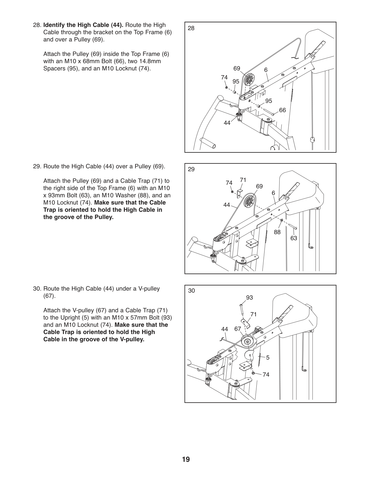
Attach the Pulley (69) and a Cable Trap (71) to the right side of the Top Frame (6) with an M10 x 93mm Bolt (63), an M10 Washer (88), and an M10 Locknut (74). Make sure that the Cable
Trap is oriented to hold the High Cable in the groove of the Pulley.
74
74 71
69
69
88
44
44
6 95
95
66
6
Attach the Pulley (69) inside the Top Frame (6) with an M10 x 68mm Bolt (66), two 14.8mm Spacers (95), and an M10 Locknut (74).
63
(67). Attach the V-pulley (67) and a Cable Trap (71) to the Upright (5) with an M10 x 57mm Bolt (93) and an M10 Locknut (74). Make sure that the Cable Trap is oriented to hold the High Cable in the groove of the V-pulley.
30
93
71
6744
5
74
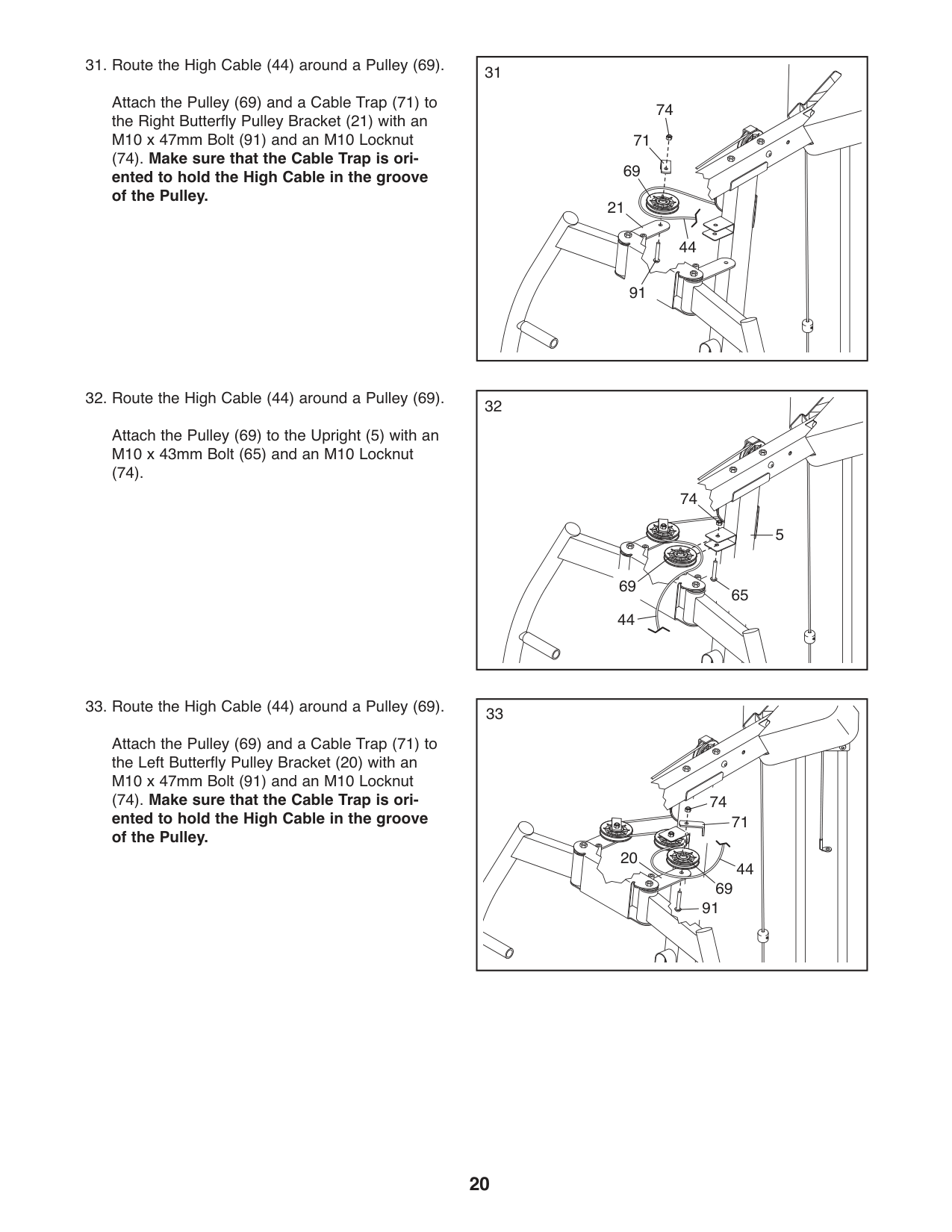
Attach the Pulley (69) and a Cable Trap (71) to the Right Butterfly Pulley Bracket (21) with an M10 x 47mm Bolt (91) and an M10 Locknut
(74). Make sure that the Cable Trap is oriented to hold the High Cable in the groove of the Pulley.
31
74 71
69 21
44
91
Attach the Pulley (69) to the Upright (5) with an M10 x 43mm Bolt (65) and an M10 Locknut
(74).
5
65
74
44
69
74
71
44 69
20
91
Attach the Pulley (69) and a Cable Trap (71) to the Left Butterfly Pulley Bracket (20) with an M10 x 47mm Bolt (91) and an M10 Locknut
#### (74). Make sure that the Cable Trap is oriented to hold the High Cable in the groove of the Pulley.
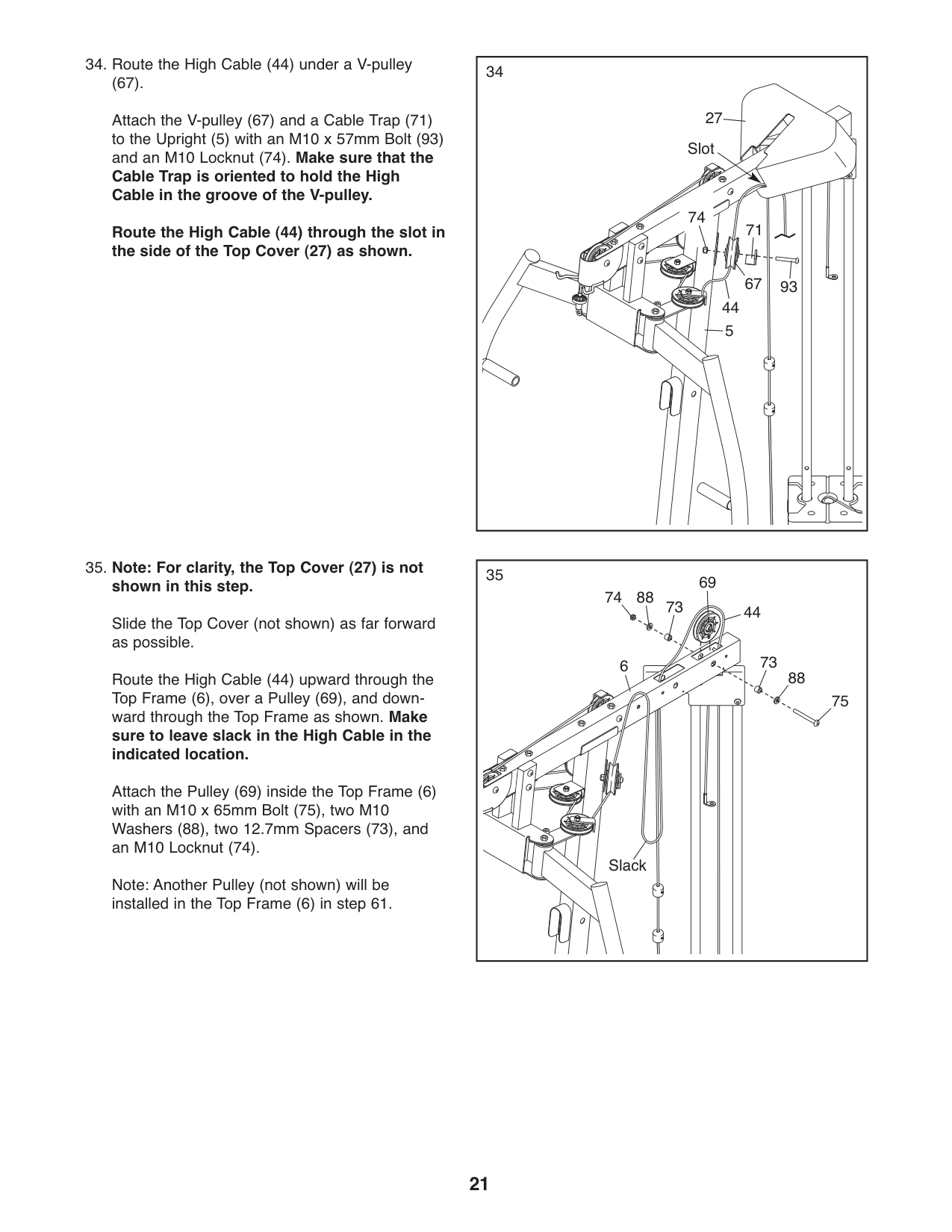
3434.RoutetheHighCable(44)underaV-pulley
(67). Attach the V-pulley (67) and a Cable Trap (71) to the Upright (5) with an M10 x 57mm Bolt (93) and an M10 Locknut (74). Make sure that the Cable Trap is oriented to hold the High Cable in the groove of the V-pulley.
27 Slot
74
71
Route the High Cable (44) through the slot in the side of the Top Cover (27) as shown.
67
93 44
5
#### 35. Note: For clarity, the Top Cover (27) is notshown in this step.
Slide the Top Cover (not shown) as far forward as possible.
Route the High Cable (44) upward through the Top Frame (6), over a Pulley (69), and downward through the Top Frame as shown. Make sure to leave slack in the High Cable in the indicated location.
Attach the Pulley (69) inside the Top Frame (6) with an M10 x 65mm Bolt (75), two M10 Washers (88), two 12.7mm Spacers (73), and an M10 Locknut (74).
Note: Another Pulley (not shown) will be installed in the Top Frame (6) in step 61.
35
8874
73
69
6
44
73
88
75
Slack
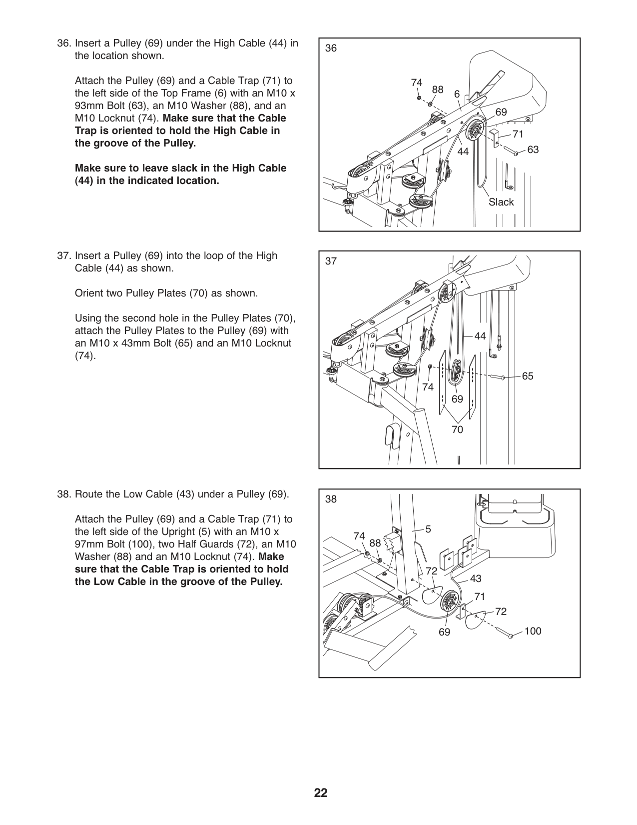
36
Attach the Pulley (69) and a Cable Trap (71) to the left side of the Top Frame (6) with an M10 x 93mm Bolt (63), an M10 Washer (88), and an M10 Locknut (74). Make sure that the Cable Trap is oriented to hold the High Cable in the groove of the Pulley.
74
88
6
69
71
63
44
Make sure to leave slack in the High Cable
(44) in the indicated location.
Slack
3737.InsertaPulley(69)intotheloopoftheHigh Cable (44) as shown. Orient two Pulley Plates (70) as shown. Using the second hole in the Pulley Plates (70), attach the Pulley Plates to the Pulley (69) with an M10 x 43mm Bolt (65) and an M10 Locknut
(74).
65
74
44
3838.RoutetheLowCable(43)underaPulley(69).
Attach the Pulley (69) and a Cable Trap (71) to the left side of the Upright (5) with an M10 x 97mm Bolt (100), two Half Guards (72), an M10 Washer (88) and an M10 Locknut (74). Make sure that the Cable Trap is oriented to hold the Low Cable in the groove of the Pulley.
5 74
88
72
43
71
72
100
69
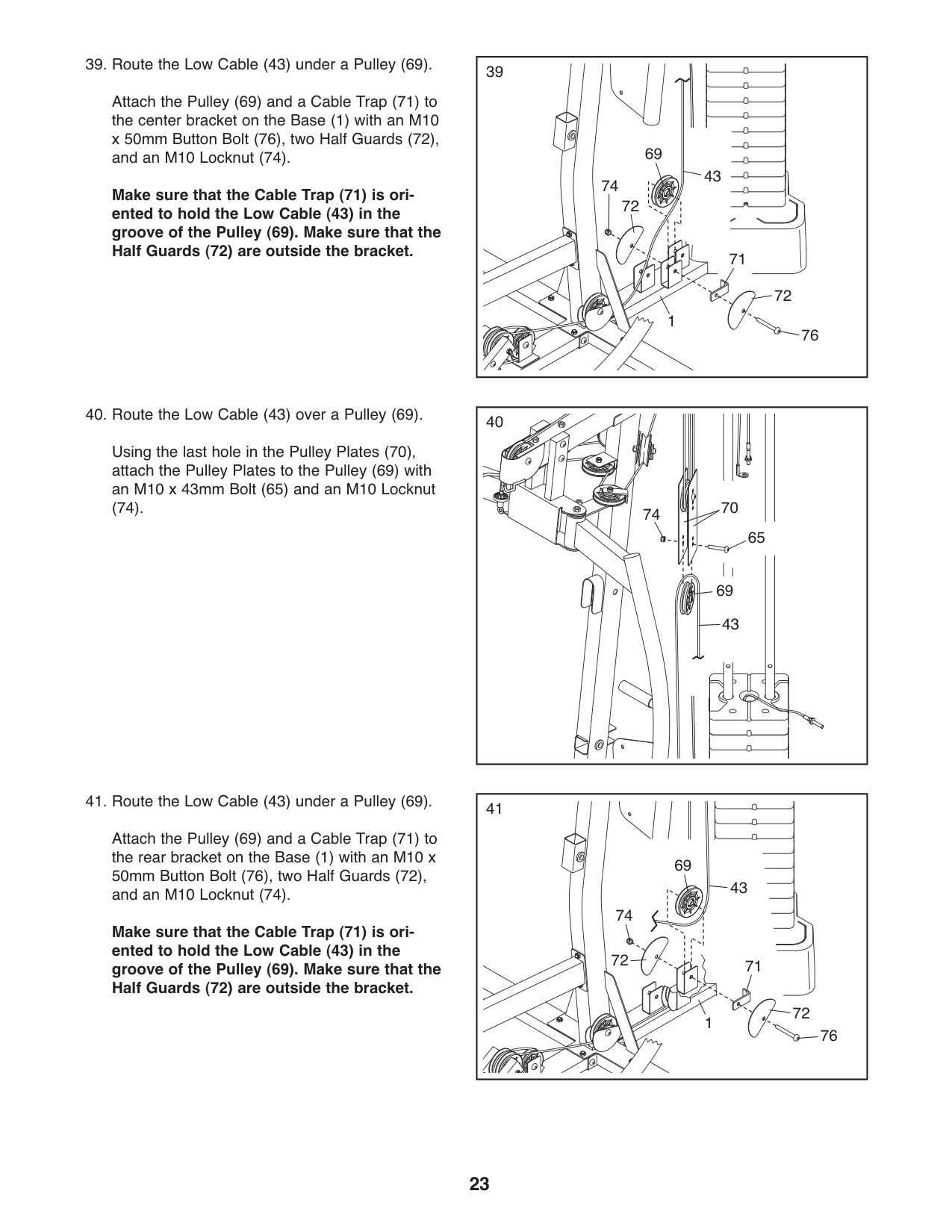
Attach the Pulley (69) and a Cable Trap (71) to the center bracket on the Base (1) with an M10 x 50mm Button Bolt (76), two Half Guards (72), and an M10 Locknut (74).
Make sure that the Cable Trap (71) is oriented to hold the Low Cable (43) in the groove of the Pulley (69). Make sure that the Half Guards (72) are outside the bracket.
39
69
43 72
74
76
72 1
Using the last hole in the Pulley Plates (70), attach the Pulley Plates to the Pulley (69) with an M10 x 43mm Bolt (65) and an M10 Locknut
(74).
40
71
74 70
65
69 43
4141.RoutetheLowCable(43)underaPulley(69).
Attach the Pulley (69) and a Cable Trap (71) to the rear bracket on the Base (1) with an M10 x 50mm Button Bolt (76), two Half Guards (72), and an M10 Locknut (74).
Make sure that the Cable Trap (71) is oriented to hold the Low Cable (43) in the groove of the Pulley (69). Make sure that the Half Guards (72) are outside the bracket.
69
43
74
72
71
72 1
76
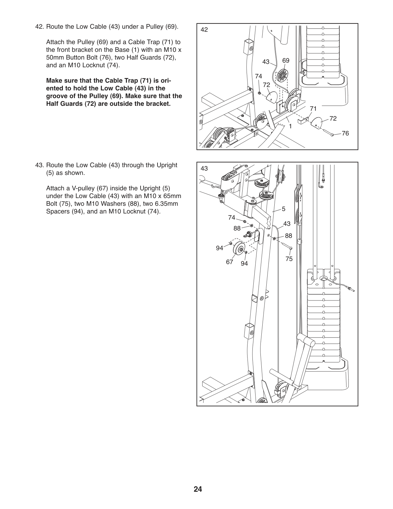
4242.RoutetheLowCable(43)underaPulley(69).
Attach the Pulley (69) and a Cable Trap (71) to the front bracket on the Base (1) with an M10 x 50mm Button Bolt (76), two Half Guards (72), and an M10 Locknut (74).
69
43
74
Make sure that the Cable Trap (71) is oriented to hold the Low Cable (43) in the groove of the Pulley (69). Make sure that the Half Guards (72) are outside the bracket.
72
71
72
1
76
4343.RoutetheLowCable(43)throughtheUpright
(5) as shown. Attach a V-pulley (67) inside the Upright (5) under the Low Cable (43) with an M10 x 65mm Bolt (75), two M10 Washers (88), two 6.35mm Spacers (94), and an M10 Locknut (74). 5
74
43
88
88
94
75
9467
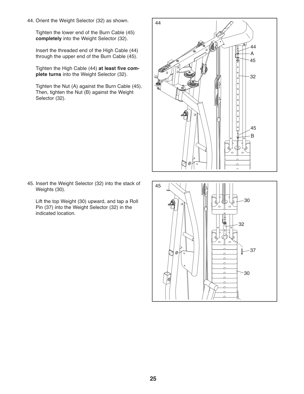
4444.OrienttheWeightSelector(32)asshown.
Tighten the lower end of the Burn Cable (45) completely into the Weight Selector (32).
Insert the threaded end of the High Cable (44) through the upper end of the Burn Cable (45).
Tighten the High Cable (44) at least five complete turns into the Weight Selector (32).
Tighten the Nut (A) against the Burn Cable (45). Then, tighten the Nut (B) against the Weight Selector (32).
45
32
A
45
30
32
37
30
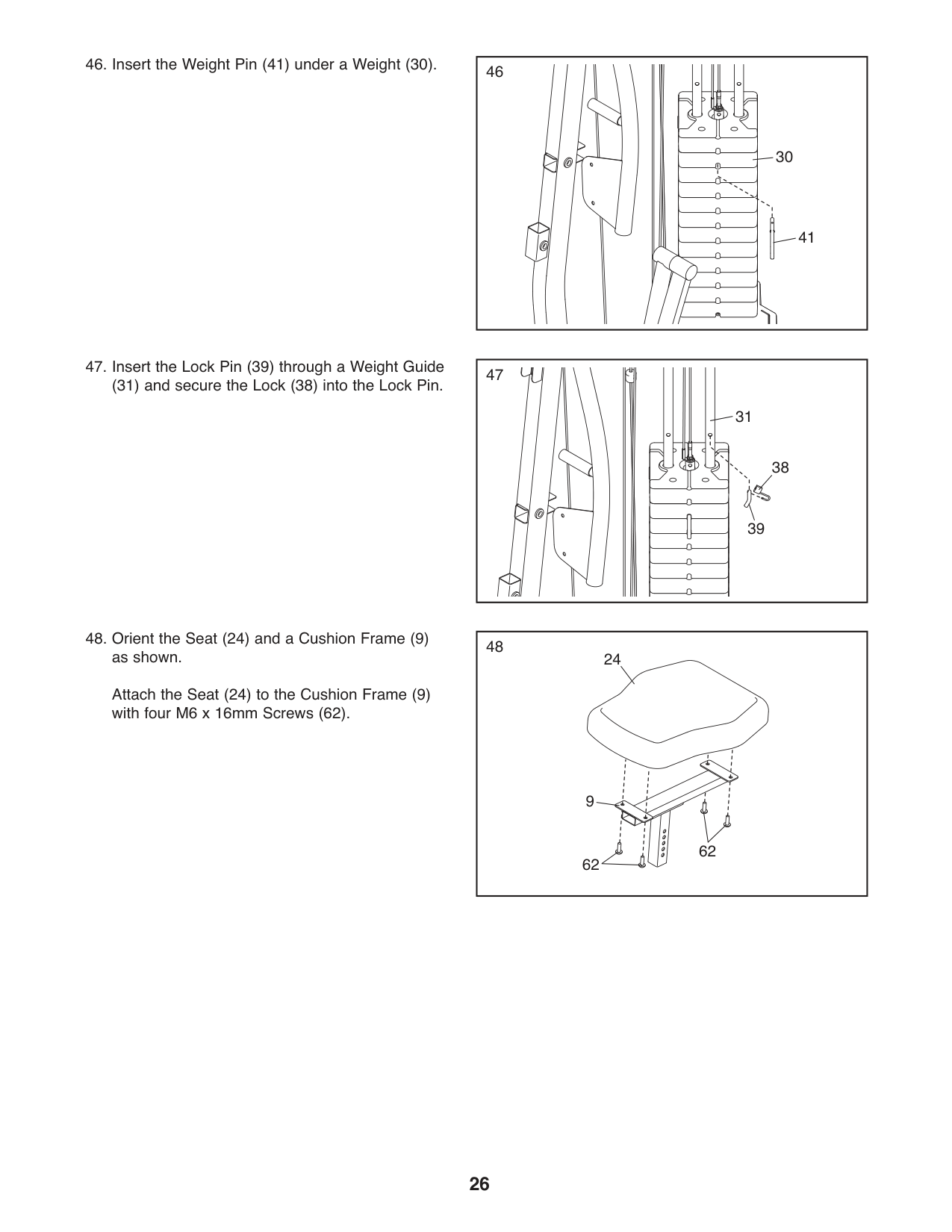
4646.InserttheWeightPin(41)underaWeight(30).
30
41
47
31
38
39
4848.OrienttheSeat(24)andaCushionFrame(9) as shown. Attach the Seat (24) to the Cushion Frame (9) with four M6 x 16mm Screws (62).
24
9
62
62
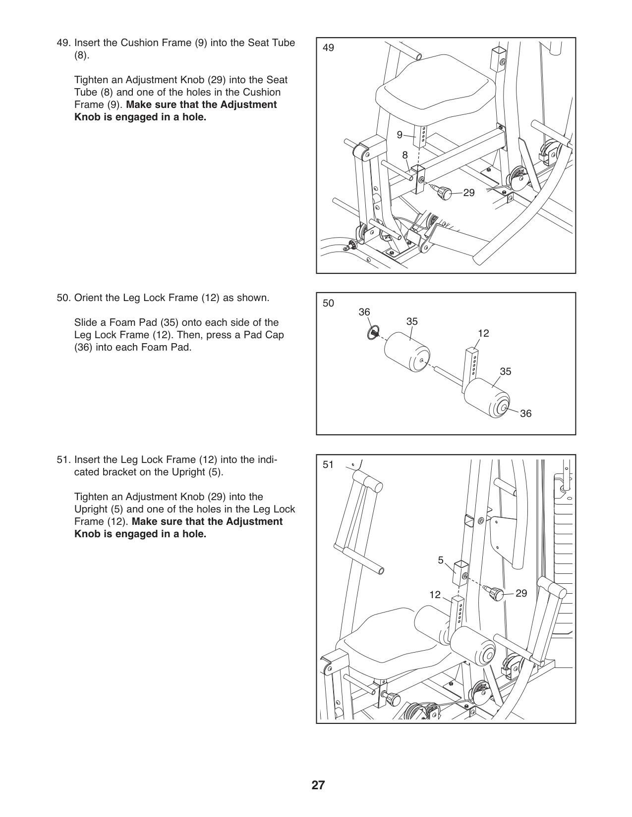
|49
29
9
8| |---|
(8). Tighten an Adjustment Knob (29) into the Seat Tube (8) and one of the holes in the Cushion Frame (9). Make sure that the Adjustment Knob is engaged in a hole.
5050.OrienttheLegLockFrame(12)asshown.
36
35
Slide a Foam Pad (35) onto each side of the Leg Lock Frame (12). Then, press a Pad Cap
12
(36) into each Foam Pad.
35
36
51
5
2912
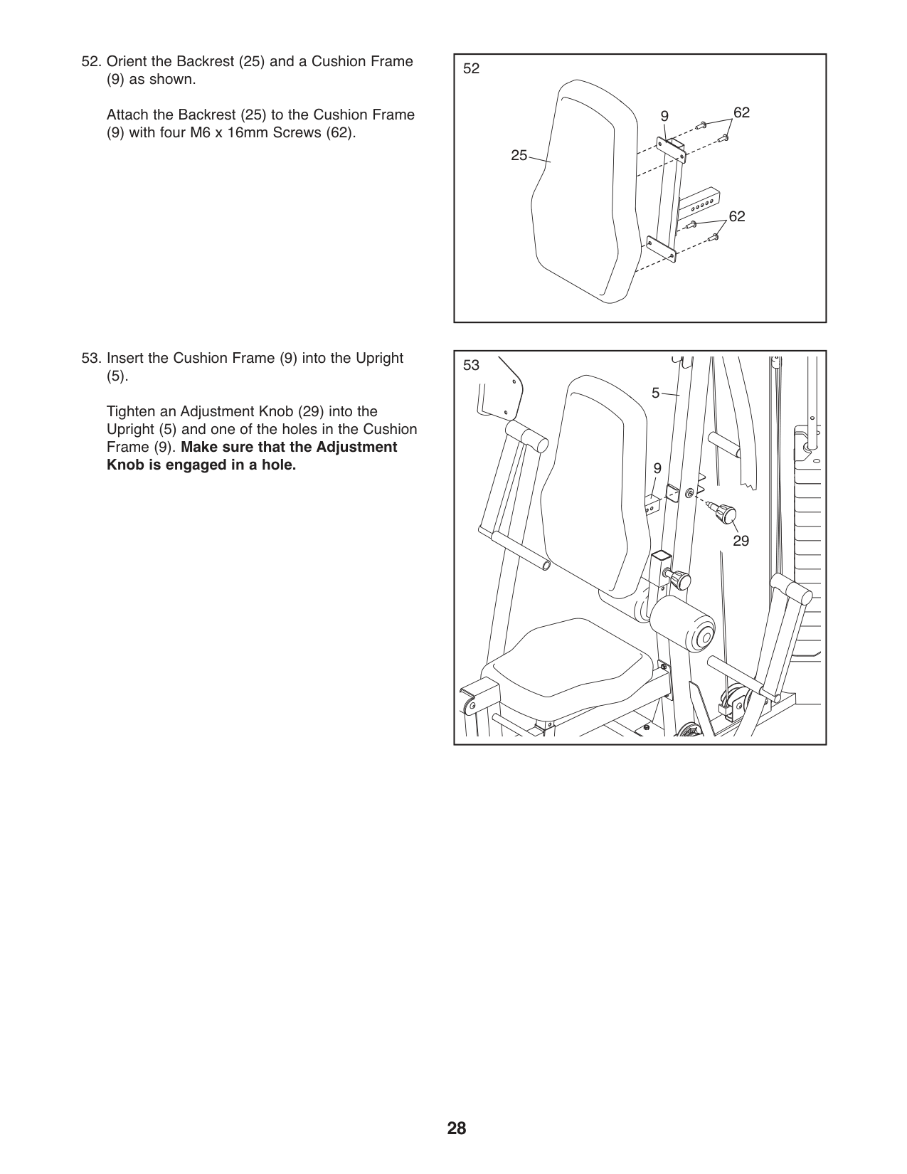
5252.OrienttheBackrest(25)andaCushionFrame
(9) as shown. Attach the Backrest (25) to the Cushion Frame
62
9
(9) with four M6 x 16mm Screws (62).
25
62
(5). Tighten an Adjustment Knob (29) into the Upright (5) and one of the holes in the Cushion Frame (9). Make sure that the Adjustment Knob is engaged in a hole.
53
5
9
29
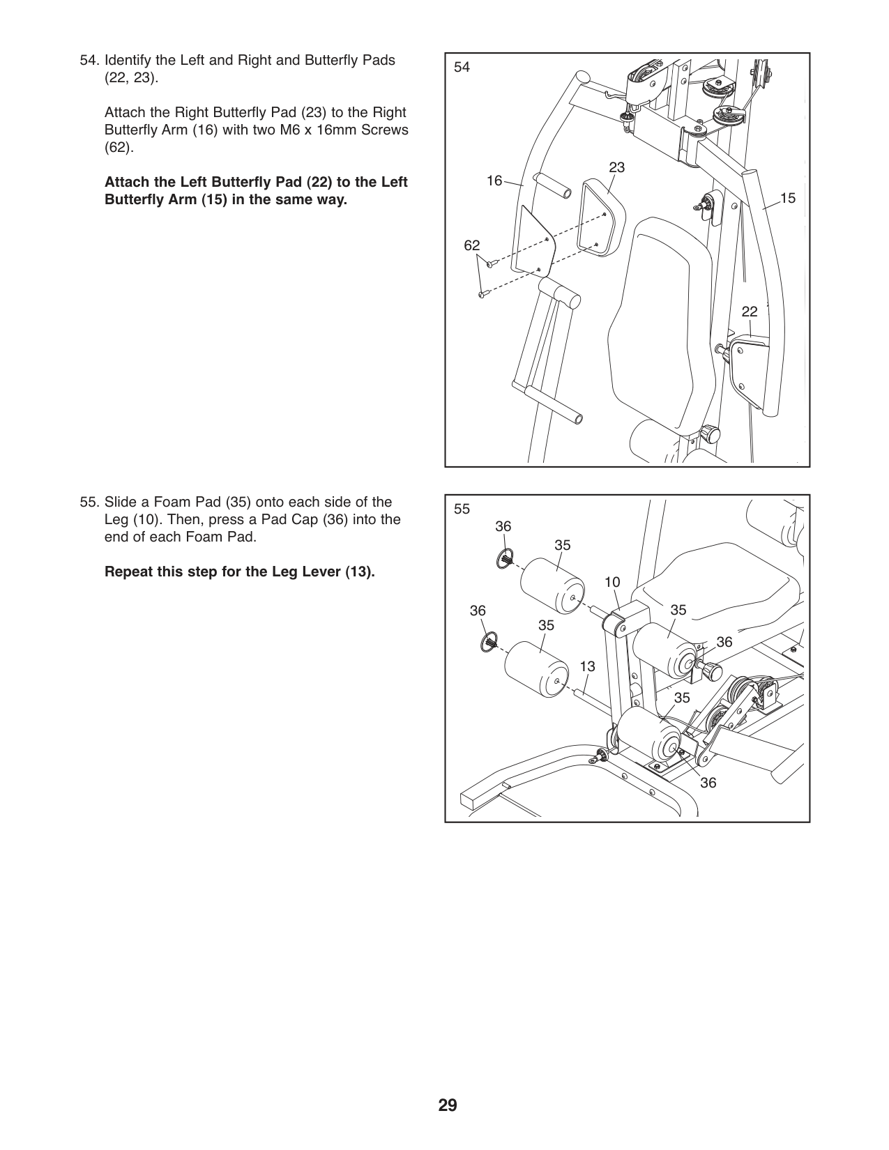
5454.IdentifytheLeftandRightandButterflyPads (22, 23).
Attach the Right Butterfly Pad (23) to the Right Butterfly Arm (16) with two M6 x 16mm Screws (62).
23 16
Attach the Left Butterfly Pad (22) to the Left Butterfly Arm (15) in the same way.
62
22
15
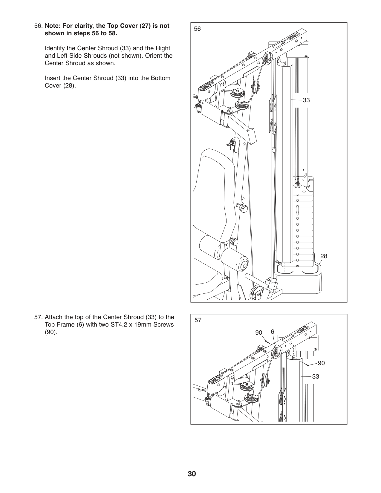
5555.SlideaFoamPad(35)ontoeachsideofthe Leg (10). Then, press a Pad Cap (36) into the end of each Foam Pad.
36
35
#### Repeat this step for the Leg Lever (13).
10
35
36
35
36
13
35
36
|56
28
33
| |---|
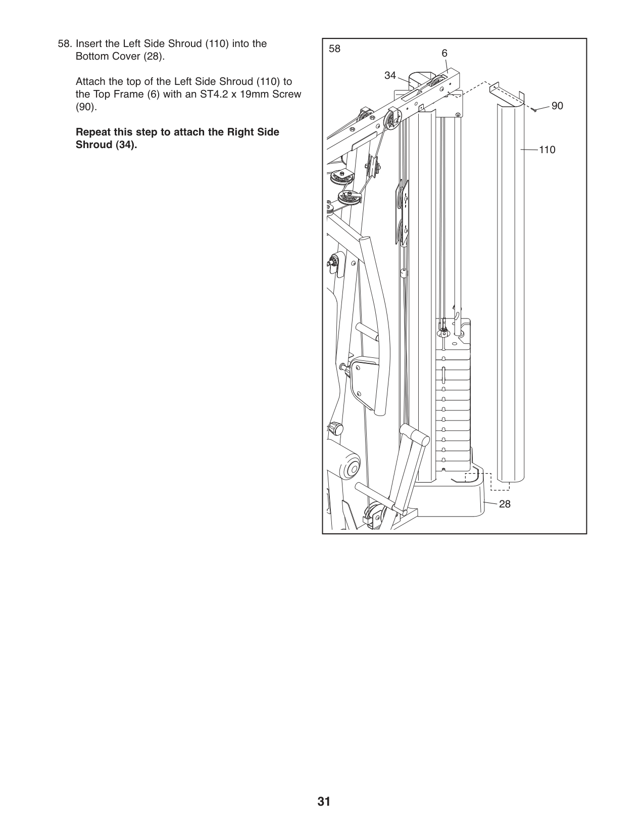
shown in steps 56 to 58.
Identify the Center Shroud (33) and the Right and Left Side Shrouds (not shown). Orient the Center Shroud as shown.
Insert the Center Shroud (33) into the Bottom Cover (28).
5757.AttachthetopoftheCenterShroud(33)tothe Top Frame (6) with two ST4.2 x 19mm Screws
(90). 90 6
90 33
Attach the top of the Left Side Shroud (110) to the Top Frame (6) with an ST4.2 x 19mm Screw
(90).
Repeat this step to attach the Right Side Shroud (34).
|58
90
110
34
6
28
| |---|
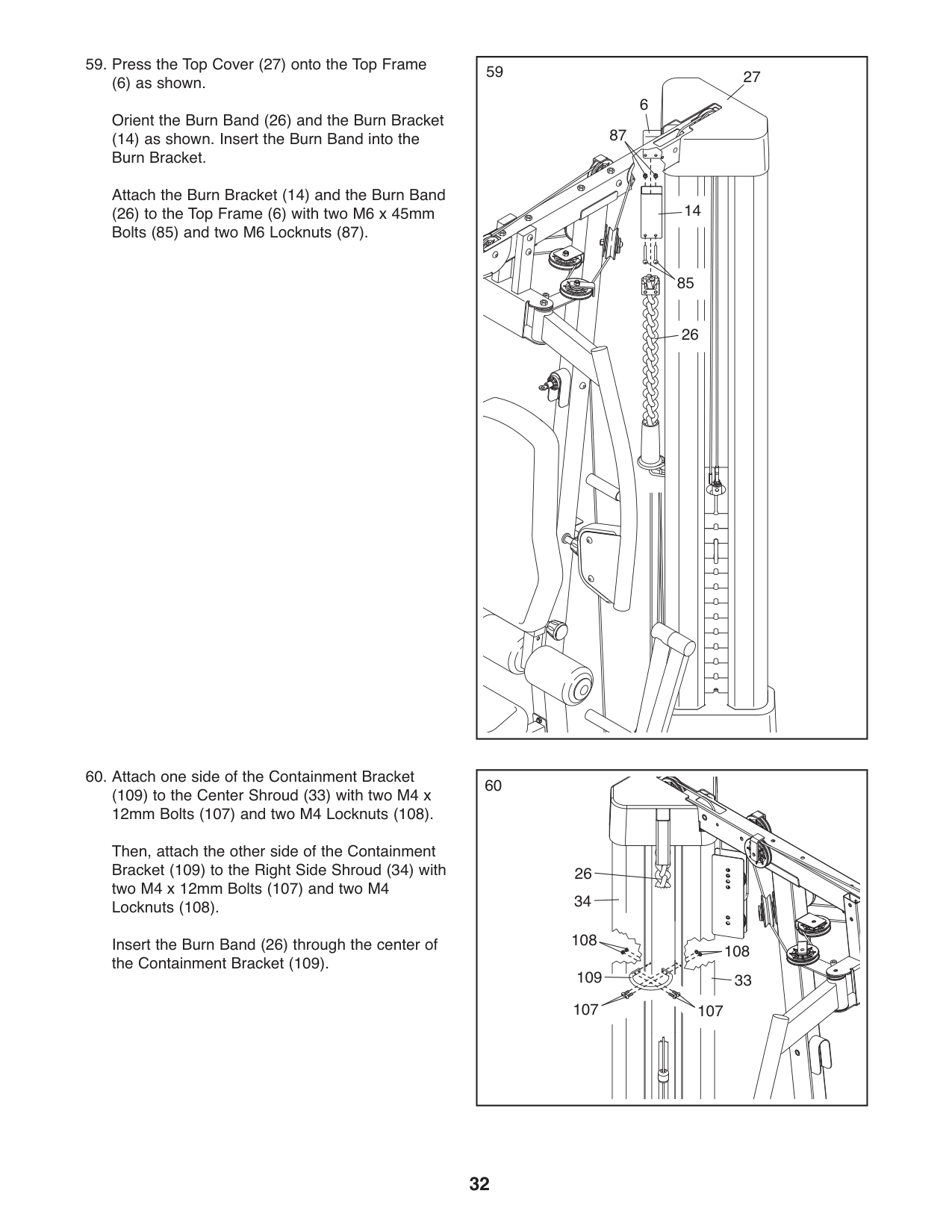
(6) as shown. Orient the Burn Band (26) and the Burn Bracket
(14) as shown. Insert the Burn Band into the Burn Bracket.
Attach the Burn Bracket (14) and the Burn Band
(26) to the Top Frame (6) with two M6 x 45mm Bolts (85) and two M6 Locknuts (87).
14
85
26
(109) to the Center Shroud (33) with two M4 x 12mm Bolts (107) and two M4 Locknuts (108).
Then, attach the other side of the Containment Bracket (109) to the Right Side Shroud (34) with two M4 x 12mm Bolts (107) and two M4 Locknuts (108).
Insert the Burn Band (26) through the center of the Containment Bracket (109).
59 27
6
87
| | | |---|---| | | |
60
26
34
109
33
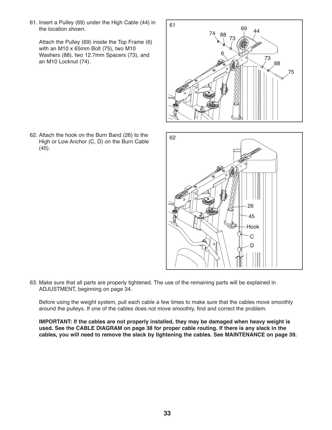
6161.InsertaPulley(69)undertheHighCable(44)in the location shown. Attach the Pulley (69) inside the Top Frame (6) with an M10 x 65mm Bolt (75), two M10 Washers (88), two 12.7mm Spacers (73), and an M10 Locknut (74).
8874
73
69 44
6
| | | |---|---| | | |
73
88
75
6262.AttachthehookontheBurnBand(26)tothe High or Low Anchor (C, D) on the Burn Cable
(45).
26 45
Hook C D
IMPORTANT: If the cables are not properly installed, they may be damaged when heavy weight is used. See the CABLE DIAGRAM on page 38 for proper cable routing. If there is any slack in the cables, you will need to remove the slack by tightening the cables. See MAINTENANCE on page 39.
ADJUSTMENT
This section explains how to adjust the weight system. See the EXERCISE GUIDELINES on page 40 for important information about how to get the most benefit from your exercise program. Also, refer to the accompanying exercise guide to see the correct form for several exercises.
Make sure that all parts are properly tightened each time the weight system is used. Replace any worn parts immediately.
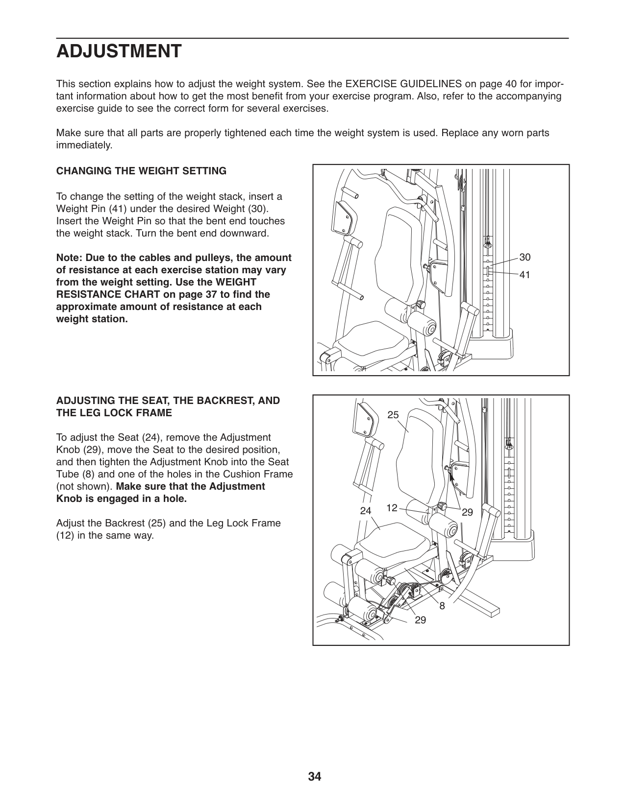
#### CHANGING THE WEIGHT SETTING
To change the setting of the weight stack, insert a Weight Pin (41) under the desired Weight (30). Insert the Weight Pin so that the bent end touches the weight stack. Turn the bent end downward.
Note: Due to the cables and pulleys, the amount of resistance at each exercise station may vary from the weight setting. Use the WEIGHT RESISTANCE CHART on page 37 to find the approximate amount of resistance at each weight station.
ADJUSTING THE SEAT,THE BACKREST,AND THE LEG LOCK FRAME
To adjust the Seat (24), remove the Adjustment Knob (29), move the Seat to the desired position, and then tighten the Adjustment Knob into the Seat Tube (8) and one of the holes in the Cushion Frame (not shown). Make sure that the Adjustment Knob is engaged in a hole.
Adjust the Backrest (25) and the Leg Lock Frame
(12) in the same way.
30
41
25
2912
24
8
29
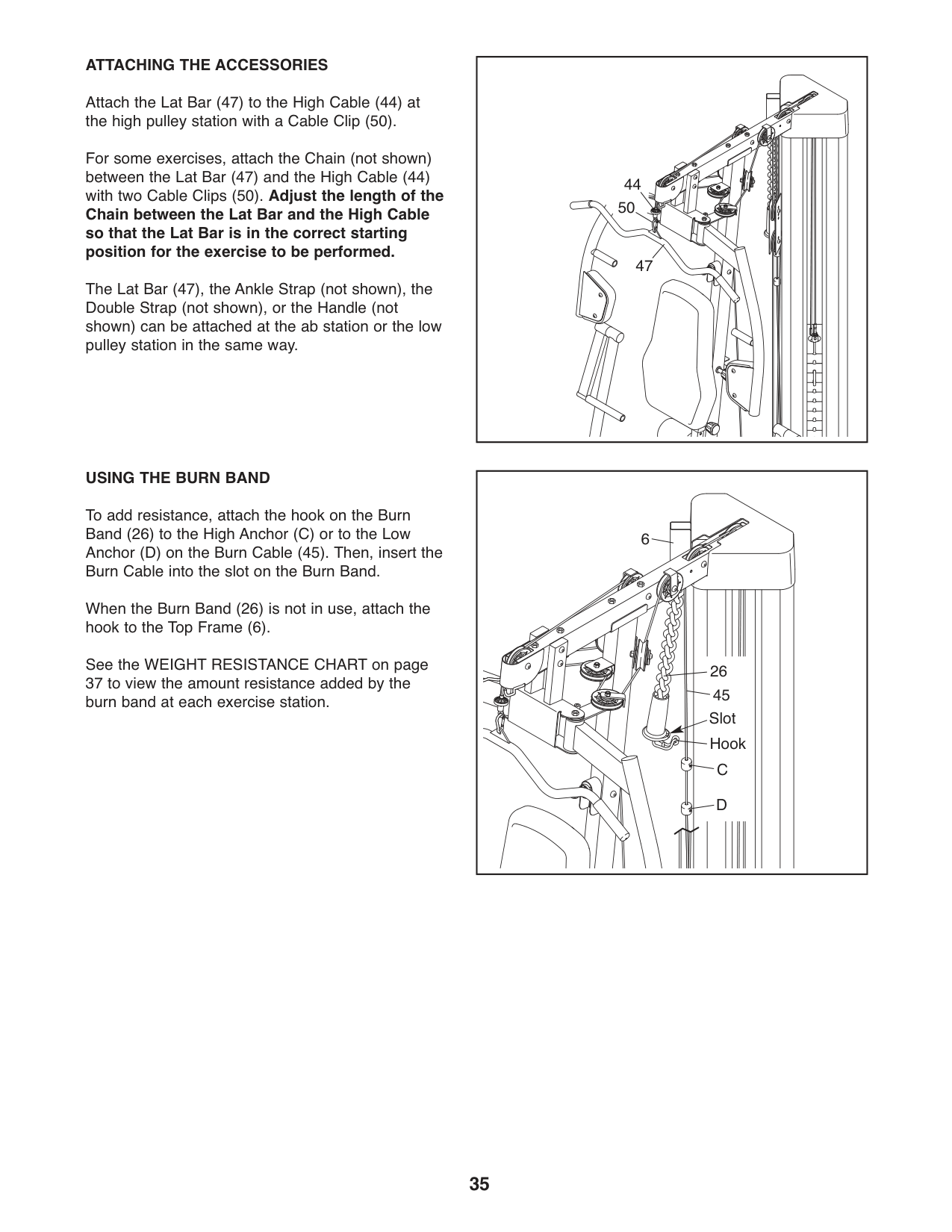
#### ATTACHING THE ACCESSORIES
Attach the Lat Bar (47) to the High Cable (44) at the high pulley station with a Cable Clip (50).
For some exercises, attach the Chain (not shown) between the Lat Bar (47) and the High Cable (44) with two Cable Clips (50). Adjust the length of the
Chain between the Lat Bar and the High Cable so that the Lat Bar is in the correct starting position for the exercise to be performed.
The Lat Bar (47), the Ankle Strap (not shown), the Double Strap (not shown), or the Handle (not shown) can be attached at the ab station or the low pulley station in the same way.
#### USING THE BURN BAND
To add resistance, attach the hook on the Burn Band (26) to the High Anchor (C) or to the Low Anchor (D) on the Burn Cable (45). Then, insert the Burn Cable into the slot on the Burn Band.
When the Burn Band (26) is not in use, attach the hook to the Top Frame (6).
See the WEIGHT RESISTANCE CHART on page
44 50
47
| | | |---|---| | | |
6
| | | |---|---| | | |
26 45
Slot
Hook
C D
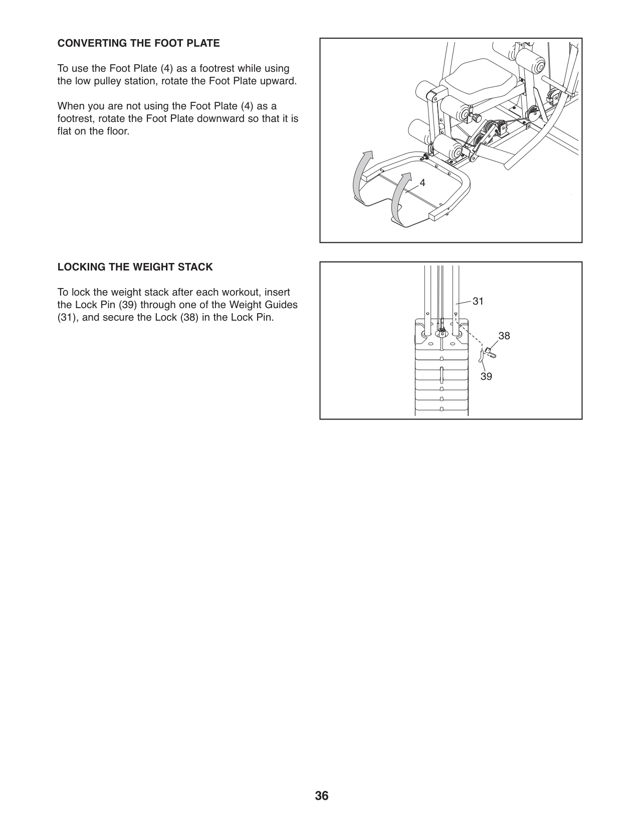
#### CONVERTING THE FOOT PLATE
To use the Foot Plate (4) as a footrest while using the low pulley station, rotate the Foot Plate upward.
When you are not using the Foot Plate (4) as a footrest, rotate the Foot Plate downward so that it is flat on the floor.
#### LOCKING THE WEIGHT STACK
To lock the weight stack after each workout, insert the Lock Pin (39) through one of the Weight Guides
(31), and secure the Lock (38) in the Lock Pin.
4
31
38
39
WEIGHT RESISTANCE CHART
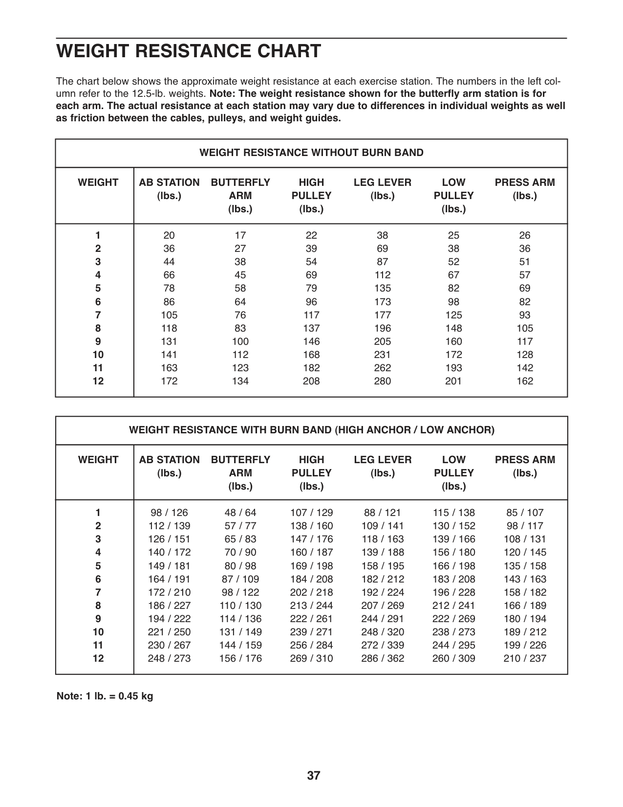
The chart below shows the approximate weight resistance at each exercise station. The numbers in the left column refer to the 12.5-lb. weights. Note: The weight resistance shown for the butterfly arm station is for each arm. The actual resistance at each station may vary due to differences in individual weights as well as friction between the cables, pulleys, and weight guides.
|WEIGHT RESISTANCE WITHOUT BURN BAND|WEIGHT RESISTANCE WITHOUT BURN BAND| |---|---| |WEIGHT|AB STATION (lbs.)
BUTTERFLY ARM (lbs.)
HIGH PULLEY (lbs.)
LEG LEVER (lbs.)
LOW PULLEY (lbs.)
PRESS ARM (lbs.)| |1
2
3
4
5
6
7
8
9
10
11
12
|20 36 44 66 78 86 105 118 131 141 163 172
17 27 38 45 58 64 76 83 100 112 123 134
22 39 54 69 79 96 117 137 146 168 182 208
38 69 87 112 135 173 177 196 205 231 262 280
25 38 52 67 82 98 125 148 160 172 193 201
26 36 51 57 69 82 93 105 117 128 142 162|
|WEIGHT RESISTANCE WITH BURN BAND (HIGH ANCHOR / LOW ANCHOR)|WEIGHT RESISTANCE WITH BURN BAND (HIGH ANCHOR / LOW ANCHOR)| |---|---| |WEIGHT|AB STATION (lbs.)
BUTTERFLY ARM (lbs.)
HIGH PULLEY (lbs.)
LEG LEVER (lbs.)
LOW PULLEY (lbs.)
PRESS ARM (lbs.)|
|1
2
3
4
5
6
7
8
9
10
11
12
|98 / 126 112 / 139 126 / 151 140 / 172 149 / 181 164 / 191 172 / 210 186 / 227 194 / 222 221 / 250 230 / 267 248 / 273
48 / 64 57 / 77 65 / 83 70 / 90 80 / 98 87 / 109 98 / 122 110 / 130 114 / 136 131 / 149 144 / 159 156 / 176
107 / 129 138 / 160 147 / 176 160 / 187 169 / 198 184 / 208 202 / 218 213 / 244 222 / 261 239 / 271 256 / 284 269 / 310
88 / 121 109 / 141 118 / 163 139 / 188 158 / 195 182 / 212 192 / 224 207 / 269 244 / 291 248 / 320 272 / 339 286 / 362
115 / 138 130 / 152 139 / 166 156 / 180 166 / 198 183 / 208 196 / 228 212 / 241 222 / 269 238 / 273 244 / 295 260 / 309
85 / 107 98 / 117 108 / 131 120 / 145 135 / 158 143 / 163 158 / 182 166 / 189 180 / 194 189 / 212 199 / 226 210 / 237|
Note: 1 lb. = 0.45 kg
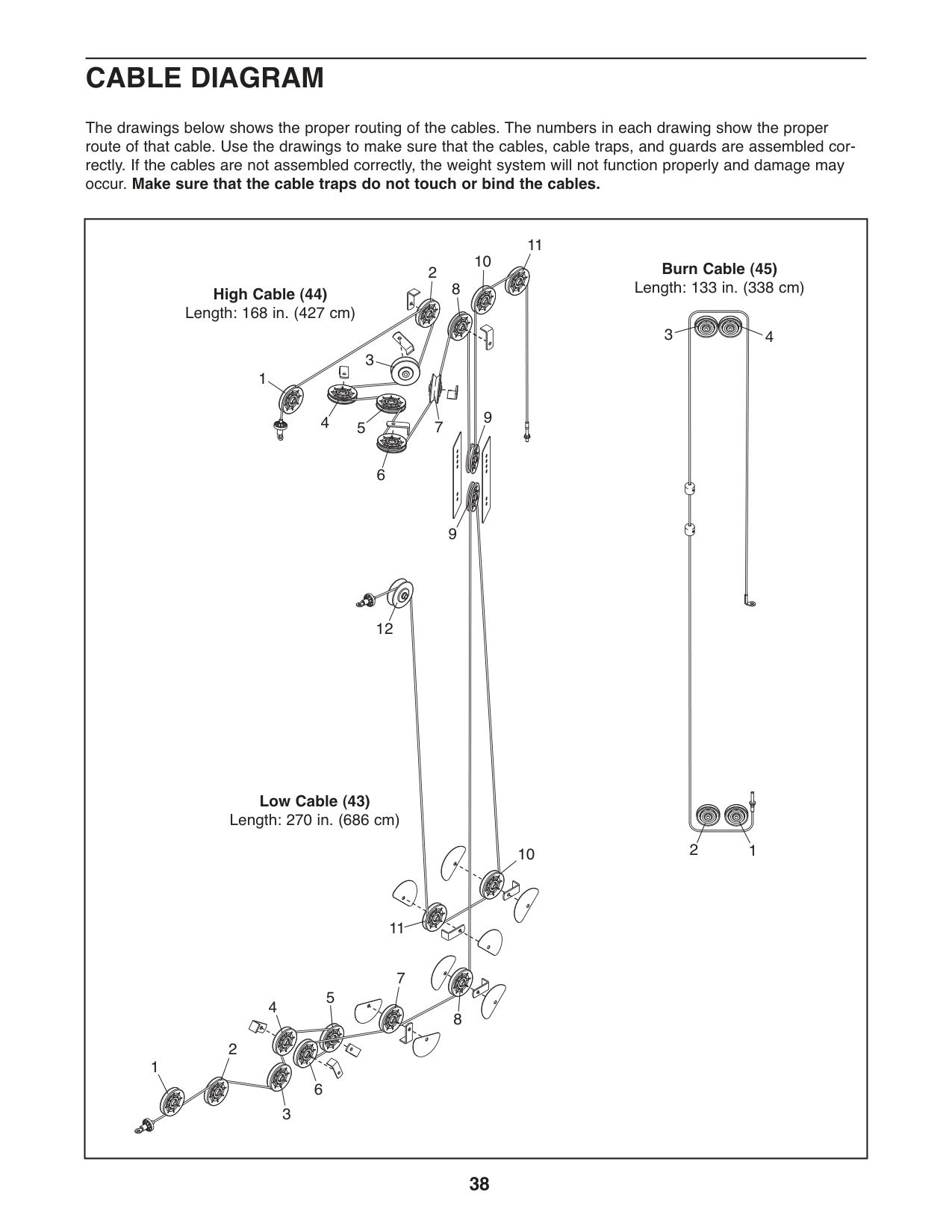
CABLE DIAGRAM
The drawings below shows the proper routing of the cables. The numbers in each drawing show the proper route of that cable. Use the drawings to make sure that the cables, cable traps, and guards are assembled correctly. If the cables are not assembled correctly, the weight system will not function properly and damage may occur. Make sure that the cable traps do not touch or bind the cables.
|1
1
1
2
2
2
3
3
4
4
5
Burn Cable (45)
Length: 133 in. (338 cm)HighCable(44) Length: 168 in. (427 cm)
Low Cable (43) Length: 270 in. (686 cm)
6
3
4
5
6
7
8
9
10
11
12
7
8
9
11
10
| |---|
MAINTENANCE
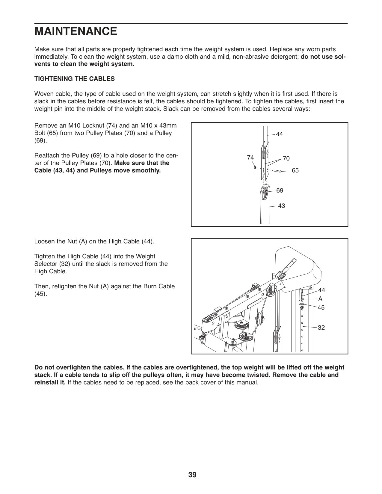
Make sure that all parts are properly tightened each time the weight system is used. Replace any worn parts immediately. To clean the weight system, use a damp cloth and a mild, non-abrasive detergent; do not use solvents to clean the weight system. TIGHTENING THE CABLES
Woven cable, the type of cable used on the weight system, can stretch slightly when it is first used. If there is slack in the cables before resistance is felt, the cables should be tightened. To tighten the cables, first insert the weight pin into the middle of the weight stack. Slack can be removed from the cables several ways:
Remove an M10 Locknut (74) and an M10 x 43mm Bolt (65) from two Pulley Plates (70) and a Pulley
(69). Reattach the Pulley (69) to a hole closer to the center of the Pulley Plates (70). Make sure that the Cable (43, 44) and Pulleys move smoothly.
74 70
65
69
Loosen the Nut (A) on the High Cable (44). Tighten the High Cable (44) into the Weight Selector (32) until the slack is removed from the High Cable. Then, retighten the Nut (A) against the Burn Cable
(45).
44
A
45
32
Do not overtighten the cables. If the cables are overtightened, the top weight will be lifted off the weight stack. If a cable tends to slip off the pulleys often, it may have become twisted. Remove the cable and reinstall it. If the cables need to be replaced, see the back cover of this manual.
EXERCISE GUIDELINES
#### FOUR TYPES OF STRENGTH WORKOUTS
Note: A “repetition” is one complete cycle of an exercise, such as one sit-up. A “set” is a series of repetitions.
Muscle Building—Work your muscles near their maximum capacity and progressively increase the intensity of your exercise. Adjust the intensity level of an individual exercise as follows:
Use your own judgment to determine the amount of resistance that is right for you. Begin with 3 sets of 8 repetitions for each exercise you perform. Rest for 3 minutes after each set. When you can complete 3 sets of 12 repetitions without difficulty, increase the amount of resistance.
Toning—Tone your muscles by working them to a moderate percentage of their capacity. Select a moderate amount of resistance and increase the number of repetitions in each set. Complete as many sets of 15 to 20 repetitions as possible without discomfort. Rest for 1 minute after each set. Work your muscles by completing more sets rather than by using high amounts of resistance.
Weight Loss—To lose weight, use a low amount of resistance and increase the number of repetitions in each set. Exercise for 20 to 30 minutes, resting for a maximum of 30 seconds between sets.
Cross Training—Combine strength training and aerobic exercise by following this type of program:
#### WORKOUT GUIDELINES
Familiarize yourself with the equipment and learn the proper form for each exercise. Use your own judgment to determine the appropriate length of time for each
workout, and the numbers of repetitions and sets to complete. Progress at your own pace and be sensitive to your bodyʼs signals. Follow each workout with at least one day of rest.
Warming Up—Start with 5 to 10 minutes of stretching and light exercise. A warm-up increases your body temperature, heart rate, and circulation in preparation for exercise.
Working Out—Include 6 to 10 different exercises in each workout. Select exercises for every major muscle group, emphasizing areas that you want to develop. To give balance and variety to your workouts, vary the exercises from workout to workout.
Cooling Down—Finish with 5 to 10 minutes of stretching. Stretching increases the flexibility of your muscles and helps to prevent post-exercise problems.
#### EXERCISE FORM
Move through the full range of motion for each exercise and move only the appropriate parts of the body. Perform the repetitions in each set smoothly and without pausing. The exertion stage of each repetition should last about half as long as the return stage. Exhale during the exertion stage of each repetition and inhale during the return stroke. Never hold your breath.
Rest for a short period of time after each set:
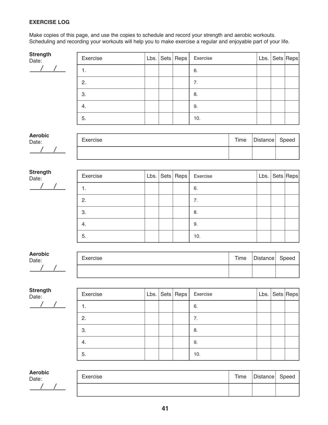
For motivation, keep a record of each workout. Write the date, the exercises performed, the resistance used, and the numbers of sets and repetitions completed. Record your weight and key body measurements once a month. To achieve good results, make exercise a regular and enjoyable part of your life.
#### EXERCISE LOG
Make copies of this page, and use the copies to schedule and record your strength and aerobic workouts. Scheduling and recording your workouts will help you to make exercise a regular and enjoyable part of your life.
Strength Date:
|Exercise|Lbs.|Sets|Reps|Exercise|Lbs.|Sets|Reps| |---|---|---|---|---|---|---|---| |1.| | | |6.| | | | |2.| | | |7.| | | | |3.| | | |8.| | | | |4.| | | |9.| | | | |5.| | | |10.| | | |
Aerobic Date:
|Exercise|Time|Distance|Speed| |---|---|---|---| | | | | |
Strength Date:
Aerobic Date:
Strength Date:
Aerobic Date:
|Exercise|Lbs.|Sets|Reps|Exercise|Lbs.|Sets|Reps| |---|---|---|---|---|---|---|---| |1.| | | |6.| | | | |2.| | | |7.| | | | |3.| | | |8.| | | | |4.| | | |9.| | | | |5.| | | |10.| | | |
|Exercise|Time|Distance|Speed| |---|---|---|---|
| | | | |
|Exercise|Lbs.|Sets|Reps|Exercise|Lbs.|Sets|Reps| |---|---|---|---|---|---|---|---| |1.| | | |6.| | | | |2.| | | |7.| | | | |3.| | | |8.| | | | |4.| | | |9.| | | | |5.| | | |10.| | | |
|Exercise|Time|Distance|Speed| |---|---|---|---| | | | | |
NOTES
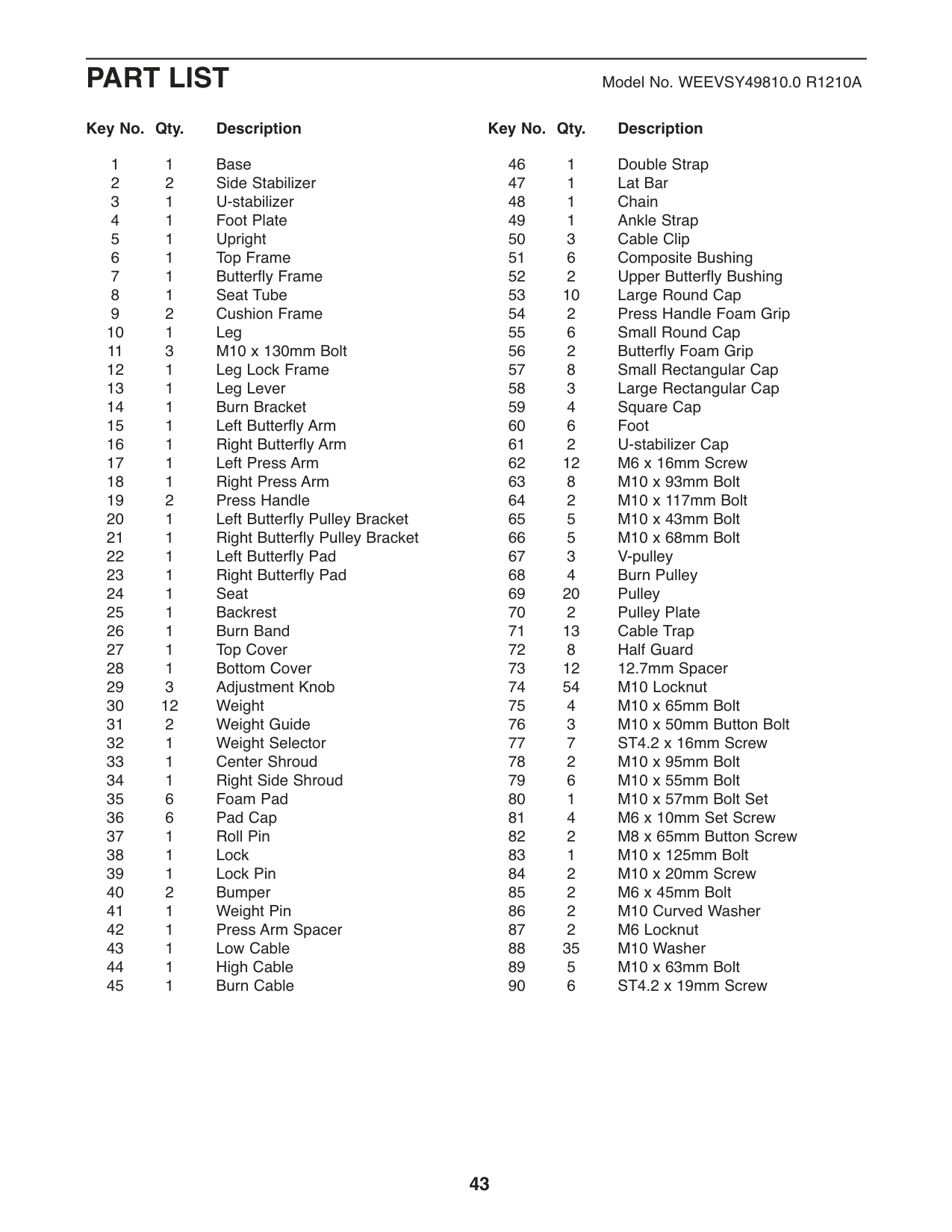
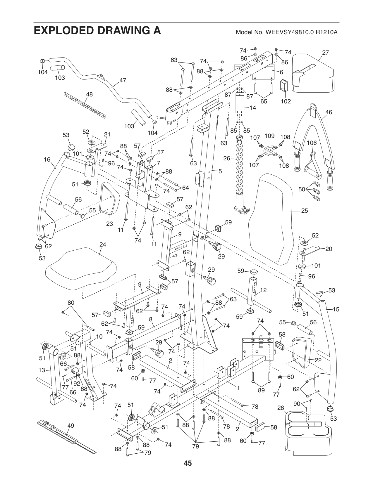
PART LIST ModelNo.WEEVSY49810.0R1210A
#### Key No. Qty. Description Key No. Qty. Description
11Base 22Side Stabilizer 3 1 U-stabilizer 41Foot Plate 51Upright 61Top Frame 71Butterfly Frame 81Seat Tube 92Cushion Frame
#### Key No. Qty. Description Key No. Qty. Description
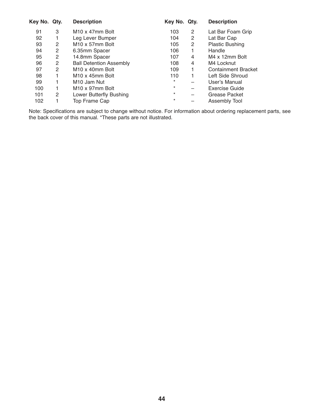
Note: Specifications are subject to change without notice. For information about ordering replacement parts, see the back cover of this manual. *These parts are not illustrated.
74 74
27
86
63 74
86
88
104
6
103
47 48
88
8787
102
65
14
46
103
8585
52
104
21
53
109107 108
106
63
57
88
57
101
74
26
16
7
96
63
107 108
74
5
88
51
64
50
74
57
56
62
55
25
11
9
52
74
11
62
20
62
29
53
101
29
96
57
9
12
53
63
88
80
74 74
15
62 62
51
57
8
74 74
56
55
59
59
60
74
58
10
| | | | |---|---|---| | | | |
29
51
74
88
51
22
2
74
66
58
74
13
60
77
92 77 88
74
62
89
74
66
77
90
74
51
74
58
28
88
53
88
49
78
51
88
74
88 88
79
79
90
36
34 35
36
36
35
36
53
36
105
74
35
19
36
54
55
53
74
105
53

55
18
55
19
57
84
88
17
57
55
42
88
53
84
74
11
53
3
82
88
61
77 66
60
60
77
82
61
4
60
77
90
| | | |---|---| | | |
37 38
39
33
| | | |---|---| | | |
| | | |---|---| | | |
30
| | | |---|---|
| | |
| | | |---|---| | | |
30
41
40 40
90
110
90
69
88 88
74
88 74
69 69
71
68 68
88
88
63
75
6969
67
74 74
97
63
67
93 65
66
69
69
71
71
74
71
65
71
69
69
81
91
81
6591
44
45
88
67
94
88
94
74
43
68 68
72
69
71
72
89
69
71
72
72 72
74
88
69
88
72
71
76
69
71
69
71
72
99
88
100
69
69
73 73
73
95
95
73
73
73
88
74 74
93
74
7474
74
83
72
74
69
76
71
71
69
91 98
89
88
75
74
88
69
73
ORDERING REPLACEMENT PARTS
To order replacement parts, please see the front cover of this manual. To help us assist you, be prepared to provide the following information when contacting us:
Part No. 306353 R1210A Printed in China © 2010 ICON IP, Inc.