
Chamberlain Chamberlain Garage Door Opener
Ask AI
— answers from the official manualAnswers from the official manual.
Common questions
Common Questions
27 totalWhat is the maximum wattage for light bulbs I can use in the garage door opener?
You can use A19 incandescent bulbs with a maximum of 100W or compact fluorescent bulbs with a maximum of 26W (100W equivalent). Do not use halogen bulbs, short neck bulbs, specialty bulbs, or LED bulbs as these may overheat the end panel or reduce remote control performance. (Page 14)
How do I test the safety reversal system?
Place a 1-1/2 inch board (or 2x4 laid flat) on the floor centered under the garage door when it is fully open, then operate the door in the down direction. The door MUST reverse on striking the obstruction. If it does not reverse, increase the down travel and repeat the test. (Page 29)
What should I do if my garage door opener displays diagnostic code 1-1?
Diagnostic code 1-1 means the safety sensors are not installed, connected, or the wires may be cut. Inspect the sensor wires for any disconnected or cut wires and repair as needed. (Page 37)
How high should the safety reversing sensors be mounted above the floor?
The safety reversing sensors must be installed no more than 6 inches (15 cm) above the garage floor to ensure proper operation of the safety reversal system. (Page 21)
What is the warranty coverage for the motor unit?
The motor unit has a 5-year warranty from the date of purchase for the first retail purchaser of the product in the residence where it is originally installed. The warranty covers defects in materials and/or workmanship. (Page 40)
How do I program a new remote control to my garage door opener?
Using the SmartControl Panel, press the navigation button below MENU, scroll to PROGRAM, select REMOTE, then press the button on the remote control you wish to program. The garage door opener lights will flash when programming is complete. You can program up to 8 remote controls. (Page 35)
Show 21 more questions
What should I do if the door will not close and the lights flash?
How long does the battery backup need to charge?
Can I use the Timer-to-Close feature with a one-piece garage door?
How do I erase all remote controls, keyless entries, and MyQ devices from the garage door opener?
What should I do if my garage door binds, sticks, or is out of balance?
What voltage and frequency does this opener require?
What additional items might I need for installation?
How often should I perform maintenance checks on this garage door opener?
What should I check before installing the garage door opener?
Will the door close if the Protector System® is not connected?
What Wi-Fi requirements do I need for the MyQ® Smartphone Control feature?
What is the maximum gap allowed between the floor and the bottom of the door?
What voltage should I use to operate this garage door opener?
Are periodic checks of the garage door opener required?
Where is the model number label located on this garage door opener?
Can I install this garage door opener on a one-piece door?
What should I do before installing the garage door opener?
Where should the garage door opener be mounted?
Do I need a Wi-Fi connection to use this garage door opener?
What should I do if my Wi-Fi signal is weak in the garage?
What safety systems does this opener have?
Full Manual
44 pages
■ Please read this manual and the enclosed safety materials carefully! ■ Fasten the manual near the garage door after installation. ■ The door WILL NOT CLOSE unless the Protector System® is connected and properly aligned. ■ Periodic checks of the garage door opener are required to ensure safe operation. ■ The model number label is located on the left side panel of your garage door opener. ■ This garage door opener is compatible with MyQ® and Security✚ 2.0™ accessories. ■ DO NOT install on a one-piece door if using devices or features providing unattended close. Unattended devices and features are to be used ONLY with sectional doors.
Contents
Preparation. . . . . . . . . . . . . . . .1-4 Assembly . . . . . . . . . . . . . . . . .5-8 Installation . . . . . . . . . . . . . . .9-26 Adjustments . . . . . . . . . . . . . 27-29 Battery Backup. . . . . . . . . . . . . . 30 Operation . . . . . . . . . . . . . . . 31-35 Using your Garage Door Opener. . . . . . . . . . . . . . . . 32 To Open the Door Manually . . . . 32 Door Control. . . . . . . . . . . . . .33-34 MyQ® Smartphone Control. . . . . 34 Remote Control and Keyless Entry . . . . . . . . . . . . . . . 35 To Erase the Memory . . . . . . . . . 35 Maintenance . . . . . . . . . . . . . . . 36 Troubleshooting. . . . . . . . . . . 37-38 Accessories. . . . . . . . . . . . . . . . 39 Warranty. . . . . . . . . . . . . . . . . . 40 Repair Parts . . . . . . . . . . . . . 41-42 1-1/4 hps* Belt Drive Garage Door Opener with MyQ® Smartphone Control and Battery Backup The Chamberlain Group, Inc. 845 Larch Avenue Elmhurst, Illinois 60126-1196 www.chamberlain.com www.mychamberlain.com Models• Lw9000Wf
• Hd950Wf
• Wd1000Wf
For Residential Use Only
MyQ® Serial Number: Affi x MyQ® Serial Number Label Here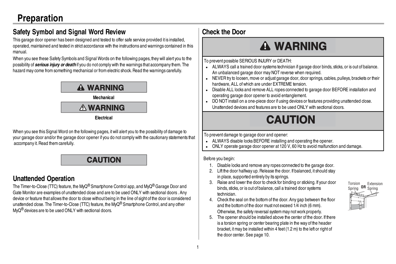
1 Safety Symbol and Signal Word Review This garage door opener has been designed and tested to offer safe service provided itis installed, operated,maintained and tested in strictaccordance with the instructions and warnings contained in this manual. When you see these Safety Symbols and Signal Words on the following pages,they will alertyou to the possibility ofserious injury ordeath ifyou do notcomply with the warnings thataccompany them.The hazard may come from something mechanical or from electric shock.Read the warnings carefully. Mechanical Electrical When you see this Signal Word on the following pages,itwill alertyou to the possibility ofdamage to your garage door and/or the garage door opener ifyou do notcomply with the cautionary statements that accompany it.Read them carefully. Unattended Operation The Timer-to-Close (TTC) feature,the MyQ® Smartphone Control app,and MyQ® Garage Door and Gate Monitor are examples ofunattended close and are to be used ONLY with sectional doors .Any device or feature thatallows the door to close withoutbeing in the line ofsightofthe door is considered unattended close.The Timer-to-Close (TTC) feature,the MyQ® Smartphone Control,and any other MyQ® devices are to be used ONLY with sectional doors. Check the Door To preventpossible SERIOUS INJURY or DEATH: l ALWAYS call a trained door systems technician ifgarage door binds,sticks,or is outofbalance. An unbalanced garage door may NOT reverse when required. l NEVER try to loosen,move or adjustgarage door,door springs,cables,pulleys,brackets or their hardware,ALL ofwhich are under EXTREME tension. l Disable ALL locks and remove ALL ropes connected to garage door BEFORE installation and operating garage door opener to avoid entanglement. l DO NOT install on a one-piece door ifusing devices or features providing unattended close. Unattended devices and features are to be used ONLY with sectional doors. To preventdamage to garage door and opener: l ALWAYS disable locks BEFORE installing and operating the opener. l ONLY operate garage door opener at120 V,60 Hz to avoid malfunction and damage. Before you begin:
Or
Preparation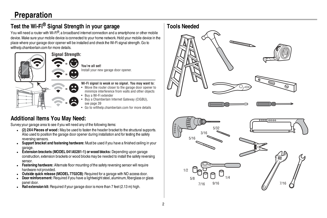
2 Test the Wi-Fi® Signal Strength in your garage You will need a router with Wi-Fi®,a broadband internetconnection and a smartphone or other mobile device.Make sure your mobile device is connected to your home network.Hold your mobile device in the place where your garage door opener will be installed and check the Wi-Fi signal strength.Go to wifihelp.chamberlain.com for more details. You’re all set! Install your new garage door opener. Wi-Fi signal is weak or no signal. You may want to:
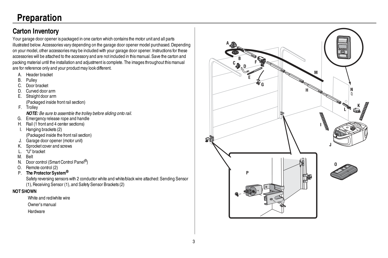
3 Carton Inventory Your garage door opener is packaged in one carton which contains the motor unitand all parts illustrated below.Accessories vary depending on the garage door opener model purchased.Depending on your model,other accessories may be included with your garage door opener.Instructions for these accessories will be attached to the accessory and are notincluded in this manual.Save the carton and packing material until the installation and adjustmentis complete.The images throughoutthis manual are for reference only and your productmay look different.
A.
Header bracketB.
PulleyC.
Door bracketD.
Curved door armE.
Straightdoor arm (Packaged inside frontrail section)F.
Trolley NOTE: Be sure to assemble the trolley before sliding onto rail.G.
Emergency release rope and handleH.
Rail (1 frontand 4 center sections)I.
Hanging brackets (2) (Packaged inside the frontrail section)J.
Garage door opener (motor unit)K.
Sprocketcover and screwsL.
“U” bracketM.
BeltN.
Door control (SmartControl Panel®)O.
Remote control (2)P.
The ProtectorSystem® Safety reversing sensors with 2 conductor white and white/black wire attached:Sending Sensor (1),Receiving Sensor (1),and Safety Sensor Brackets (2)Not Shown
White and red/white wire Owner's manual Hardware Preparation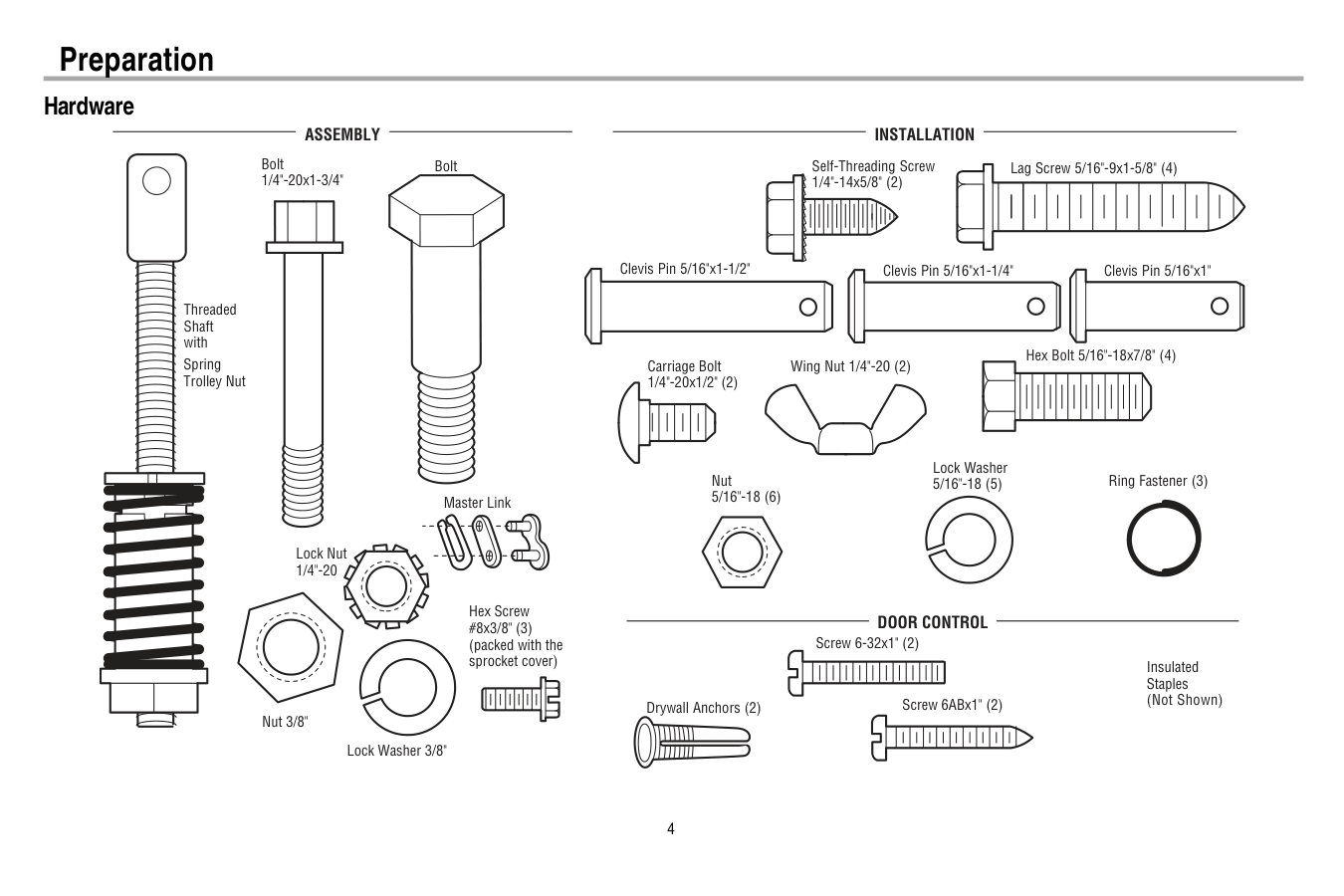
4 Hardware Clevis Pin 5/16"x1-1/2" Ring Fastener (3) Hex Bolt 5/16"-18x7/8" (4) Lock Washer 5/16"-18 (5) Nut 5/16"-18 (6) Self-Threading Screw 1/4"-14x5/8" (2) Clevis Pin 5/16"x1" Clevis Pin 5/16"x1-1/4" Carriage Bolt 1/4"-20x1/2" (2) Wing Nut 1/4"-20 (2)
Assembly
Installation
Screw 6ABx1" (2) Drywall Anchors (2) Screw 6-32x1" (2)Door Control
Insulated Staples (Not Shown) Lag Screw 5/16"-9x1-5/8" (4) Hex Screw #8x3/8" (3) (packed with the sprocket cover) Bolt 1/4"-20x1-3/4" Lock Nut 1/4"-20 Bolt Nut 3/8" Lock Washer 3/8" Master Link Spring Trolley Nut Threaded Shaft with Preparation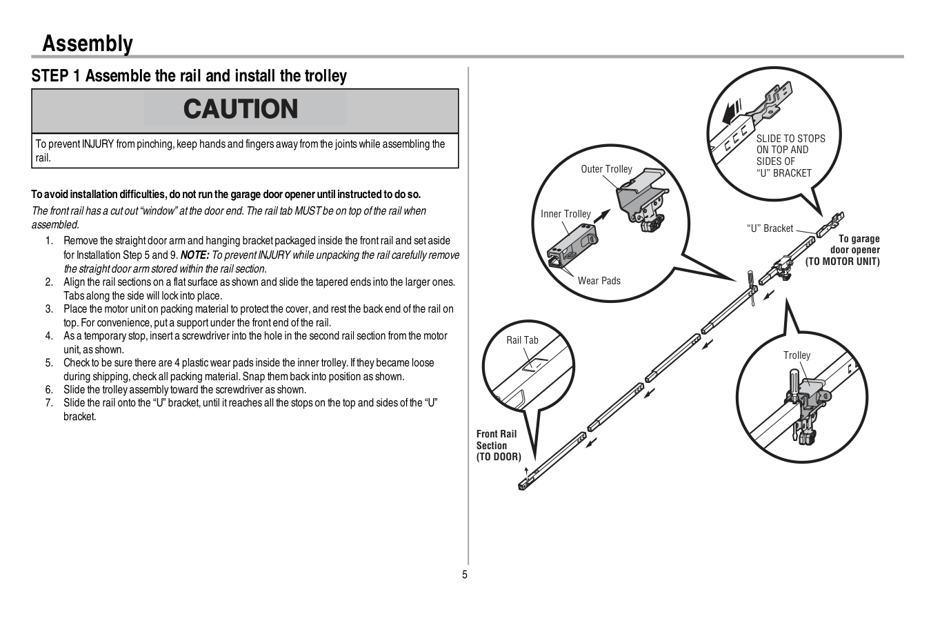
5 Assembly STEP 1 Assemble the rail and install the trolley To preventINJURY from pinching,keep hands and fingers away from the joints while assembling the rail. To avoid installation difficulties,do not run the garage dooropeneruntilinstructed to do so. The frontrail has a cutout“window” atthe door end.The rail tab MUST be on top ofthe rail when assembled.
(To Motor Unit)
Front Rail Section(To Door)
“U” Bracket Outer Trolley Inner Trolley Wear PadsSlide To Stops
On Top And
Sides Of
“U” Bracket
Trolley Rail Tab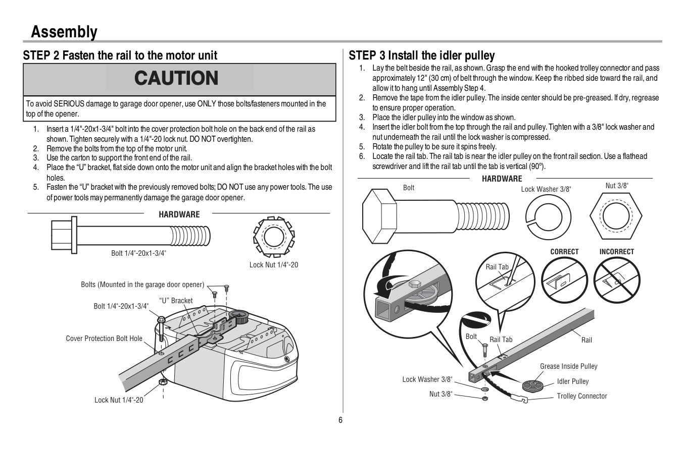
6 Assembly STEP 2 Fasten the rail to the motor unit To avoid SERIOUS damage to garage door opener,use ONLY those bolts/fasteners mounted in the top ofthe opener.
Hardware
Bolt 1/4"-20x1-3/4" Lock Nut 1/4"-20 STEP 3 Install the idler pulleyCorrect
Incorrect
Idler Pulley Grease Inside PulleyHardware
Bolt Nut 3/8" Lock Washer 3/8" Rail Tab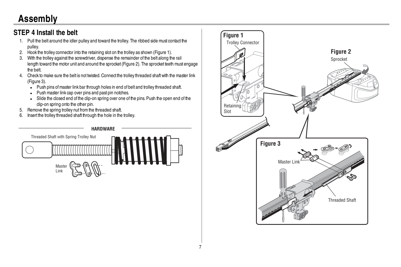
7 Assembly STEP 4 Install the belt
Hardware
Master Link Threaded Shaft with Spring Trolley Nut Sprocket Figure 3 Threaded Shaft Master Link Figure 2 Trolley Connector Figure 1 Retaining Slot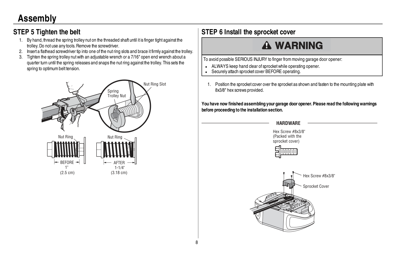
8 Assembly STEP 5 Tighten the belt
Before
1" (2.5 cm) Nut RingAfter
1-1/4" (3.18 cm) Spring Trolley Nut Nut Ring Slot STEP 6 Install the sprocket cover To avoid possible SERIOUS INJURY to finger from moving garage door opener: l ALWAYS keep hand clear ofsprocketwhile operating opener. l Securely attach sprocketcover BEFORE operating.Hardware
Hex Screw #8x3/8" Sprocket Cover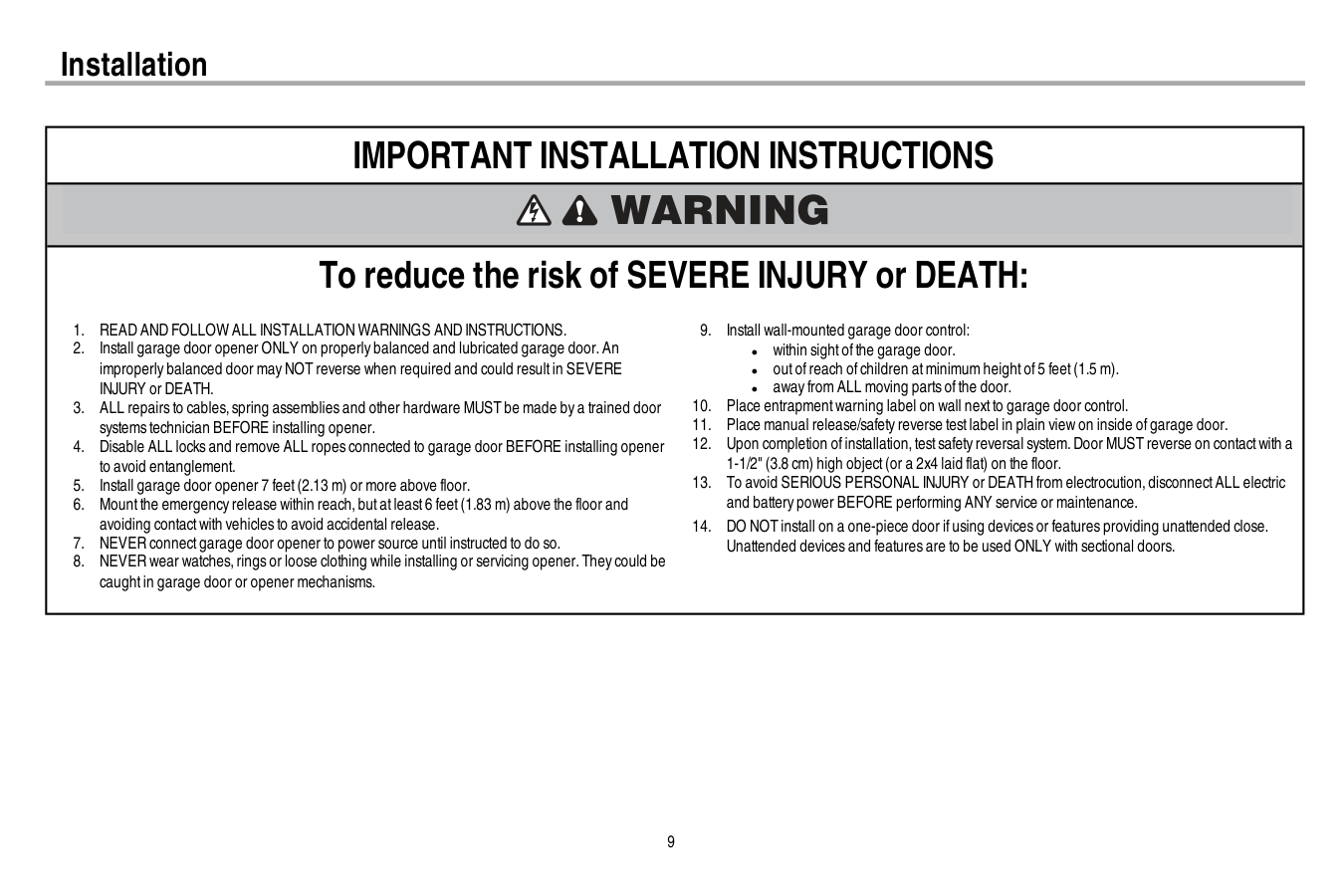
9 Installation
Important Installation Instructions
To reduce the risk of SEVERE INJURY or DEATH:Read And Follow All Installation Warnings And Instructions.
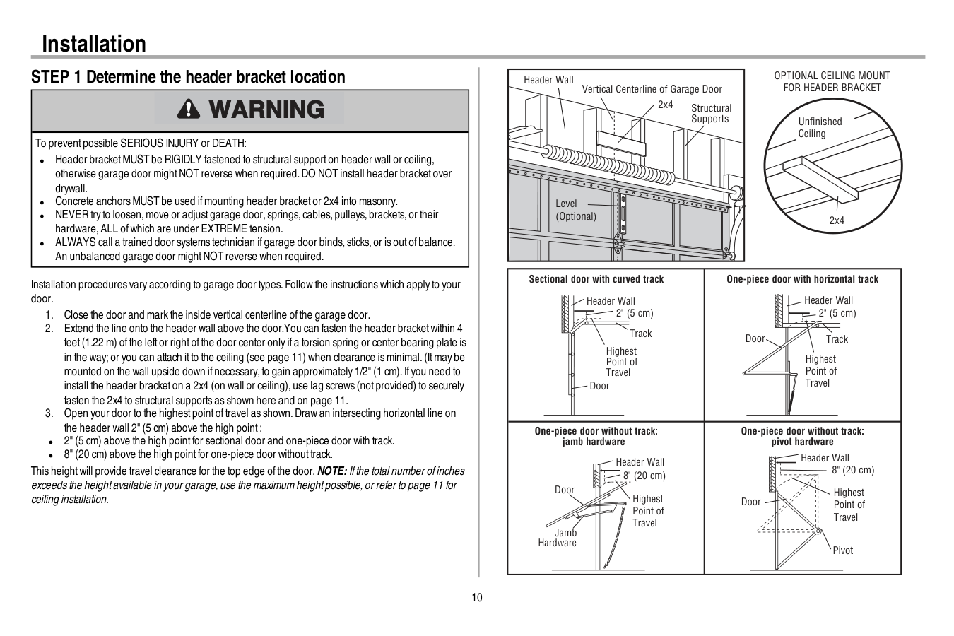
10 Installation STEP 1 Determine the header bracket location To preventpossible SERIOUS INJURY or DEATH: l Header bracketMUST be RIGIDLY fastened to structural supporton header wall or ceiling, otherwise garage door mightNOT reverse when required.DO NOT install header bracketover drywall. l Concrete anchors MUST be used ifmounting header bracketor 2x4 into masonry. l NEVER try to loosen,move or adjustgarage door,springs,cables,pulleys,brackets,or their hardware,ALL ofwhich are under EXTREME tension. l ALWAYS call a trained door systems technician ifgarage door binds,sticks,or is outofbalance. An unbalanced garage door mightNOT reverse when required. Installation procedures vary according to garage door types.Follow the instructions which apply to your door.
Optional Ceiling Mount
For Header Bracket
Sectional door with curved track Header Wall Track 2" (5 cm) Highest Point of Travel Door One-piece door with horizontal track Header Wall Track 2" (5 cm) Highest Point of Travel Door One-piece door without track: jamb hardware Header Wall 8" (20 cm) Highest Point of Travel Door Jamb Hardware One-piece door without track: pivot hardware Header Wall 8" (20 cm) Highest Point of Travel Door Pivot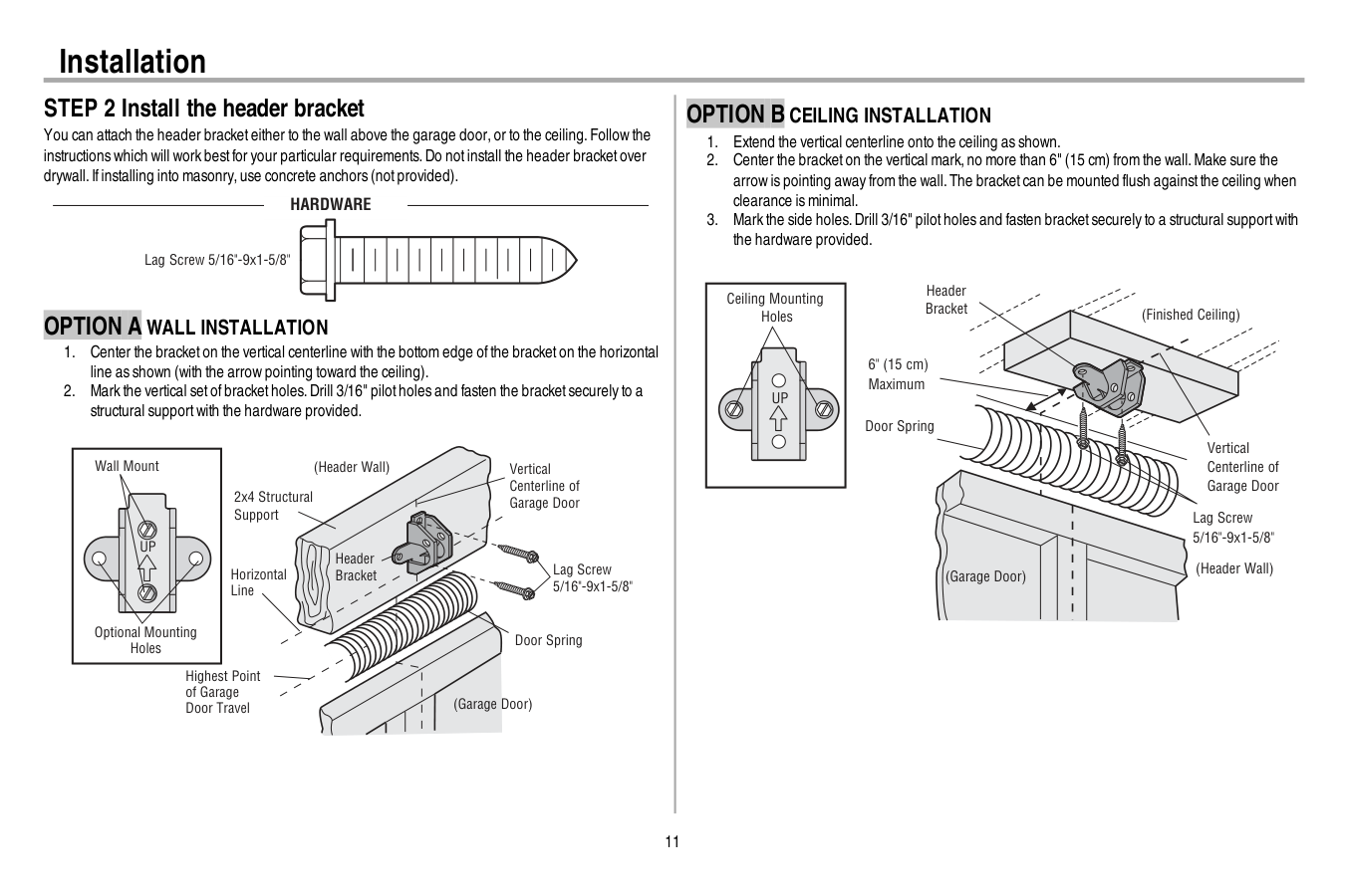
11 Installation STEP 2 Install the header bracket You can attach the header bracketeither to the wall above the garage door,or to the ceiling.Follow the instructions which will work bestfor your particular requirements.Do notinstall the header bracketover drywall.Ifinstalling into masonry,use concrete anchors (notprovided).
Hardware
Lag Screw 5/16"-9x1-5/8"Option A Wall Installation
Up
Wall Mount Optional Mounting Holes Vertical Centerline of Garage Door (Header Wall) Header Bracket 2x4 Structural Support Door Spring (Garage Door) Highest Point of Garage Door Travel Horizontal Line Lag Screw 5/16"-9x1-5/8"Option B Ceiling Installation
Up
(Header Wall) Ceiling Mounting Holes (Finished Ceiling) Vertical Centerline of Garage Door Header Bracket 6" (15 cm) Maximum Door Spring (Garage Door) Lag Screw 5/16"-9x1-5/8"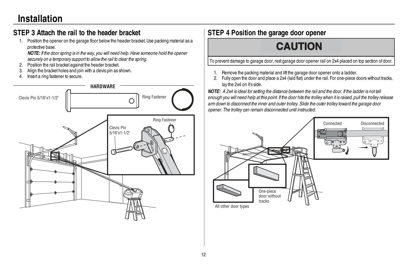
12 Installation STEP 3 Attach the rail to the header bracket
Hardware
Clevis Pin 5/16"x1-1/2" Ring Fastener Clevis Pin 5/16"x1-1/2" Ring Fastener STEP 4 Position the garage door opener To preventdamage to garage door,restgarage door opener rail on 2x4 placed on top section ofdoor.Disconnected
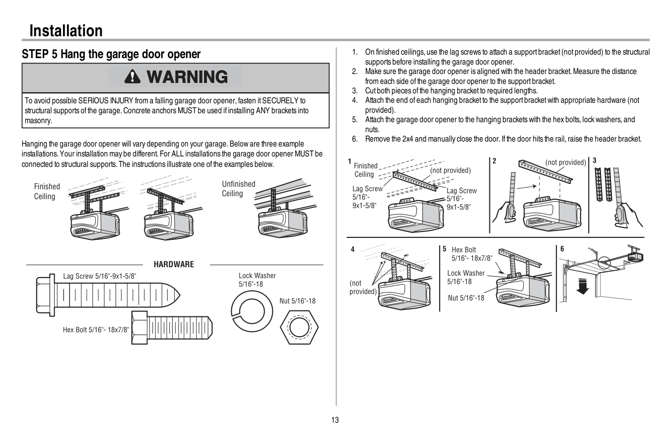
13 Installation STEP 5 Hang the garage door opener To avoid possible SERIOUS INJURY from a falling garage door opener,fasten itSECURELY to structural supports ofthe garage.Concrete anchors MUST be used ifinstalling ANY brackets into masonry. Hanging the garage door opener will vary depending on your garage.Below are three example installations.Your installation may be different.For ALL installations the garage door opener MUST be connected to structural supports.The instructions illustrate one ofthe examples below. Finished Ceiling Unfinished Ceiling
Hardware
Hex Bolt 5/16"- 18x7/8" Nut 5/16"-18 Lock Washer 5/16"-18 Lag Screw 5/16"-9x1-5/8"
14 Installation STEP 6 Install the light bulbs To preventpossible OVERHEATING ofthe end panel or lightsocket: l Use ONLY A19 incandescent(100W maximum) or compactfluorescent(26W maximum) light bulbs. l DO NOT use incandescentbulbs larger than 100W. l DO NOT use compactfluorescentlightbulbs larger than 26W (100W) equivalent. l DO NOT use halogen bulbs. l DO NOT use shortneck or specialty lightbulbs.
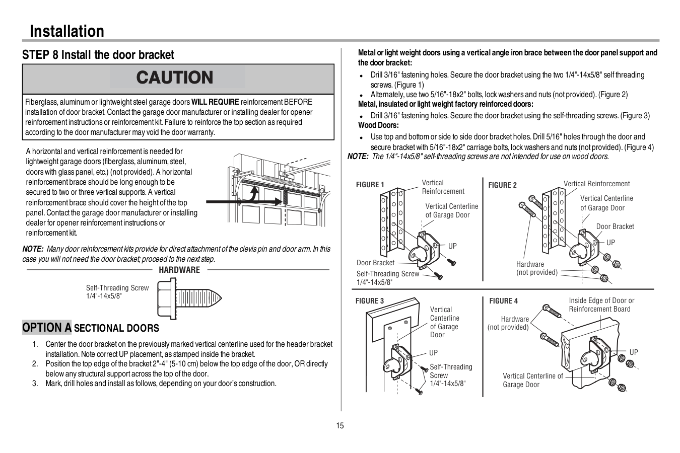
15 Installation STEP 8 Install the door bracket Fiberglass,aluminum or lightweightsteel garage doorsWILL REQUIRE reinforcementBEFORE installation ofdoor bracket.Contactthe garage door manufacturer or installing dealer for opener reinforcementinstructions or reinforcementkit.Failure to reinforce the top section as required according to the door manufacturer may void the door warranty. A horizontal and vertical reinforcementis needed for lightweightgarage doors (fiberglass,aluminum,steel, doors with glass panel,etc.) (notprovided).A horizontal reinforcementbrace should be long enough to be secured to two or three vertical supports.A vertical reinforcementbrace should cover the heightofthe top panel.Contactthe garage door manufacturer or installing dealer for opener reinforcementinstructions or reinforcementkit. NOTE: Many door reinforcementkits provide for directattachmentofthe clevis pin and door arm.In this case you will notneed the door bracket;proceed to the nextstep. Self-Threading Screw 1/4"-14x5/8"
Hardware
Option A Sectional Doors
Figure 1
Figure 3
Figure 4
Figure 2
Vertical Reinforcement Vertical Centerline of Garage DoorUp
Door Bracket Vertical Reinforcement Vertical Centerline of Garage Door Hardware (not provided) Door BracketUp
Vertical Centerline of Garage DoorUp
Vertical Centerline of Garage Door Hardware (not provided)Up
Inside Edge of Door or Reinforcement Board Self-Threading Screw 1/4"-14x5/8" Self-Threading Screw 1/4"-14x5/8"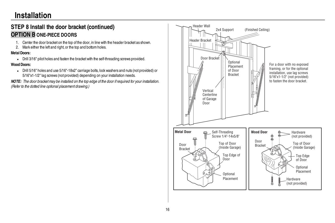
16 Installation STEP 8 Install the door bracket (continued)
Option B One-Piece Doors
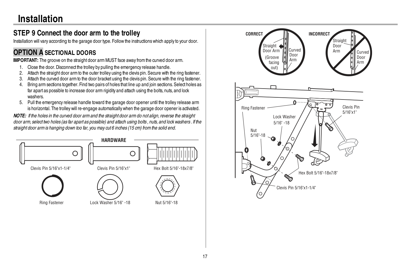
17 Installation STEP 9 Connect the door arm to the trolley Installation will vary according to the garage door type.Follow the instructions which apply to your door.
Option A Sectional Doors
IMPORTANT: The groove on the straightdoor arm MUST face away from the curved door arm.Hardware
Hex Bolt 5/16"-18x7/8" Nut 5/16"-18 Lock Washer 5/16" -18 Clevis Pin 5/16"x1" Clevis Pin 5/16"x1-1/4" Ring Fastener Straight Door Arm Curved Door Arm (Groove facing out)Correct
Straight Door Arm Curved Door ArmIncorrect
Lock Washer 5/16" -18 Nut 5/16"-18 Hex Bolt 5/16"-18x7/8" Clevis Pin 5/16"x1-1/4" Ring Fastener Clevis Pin 5/16"x1"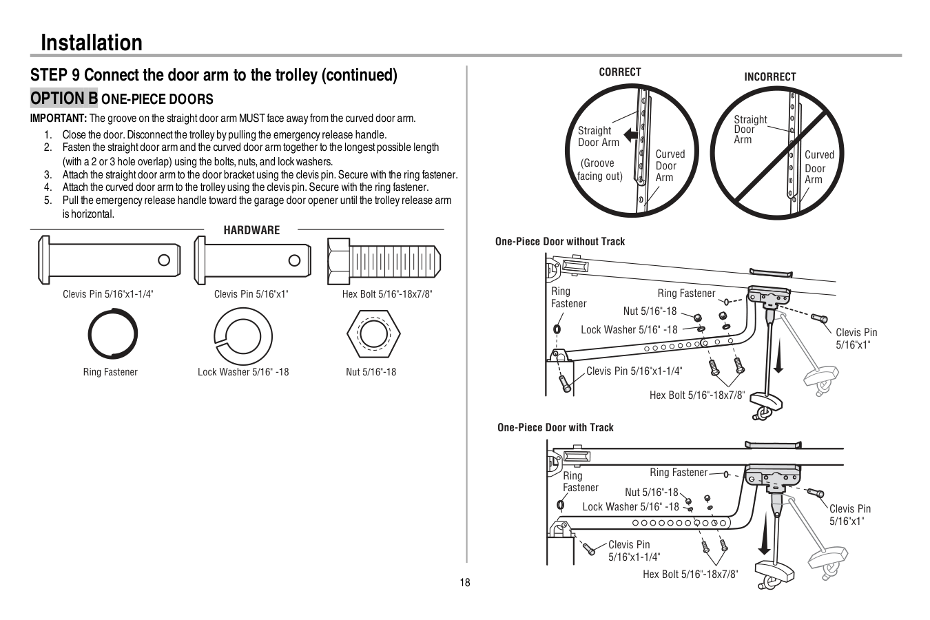
18 Installation STEP 9 Connect the door arm to the trolley (continued)
Option B One-Piece Doors
IMPORTANT: The groove on the straightdoor arm MUST face away from the curved door arm.Hardware
Hex Bolt 5/16"-18x7/8" Nut 5/16"-18 Lock Washer 5/16" -18 Clevis Pin 5/16"x1" Clevis Pin 5/16"x1-1/4" Ring Fastener One-Piece Door without Track One-Piece Door with Track Straight Door Arm Curved Door Arm (Groove facing out)Correct
Incorrect
Straight Door Arm Curved Door Arm Ring Fastener Ring Fastener Nut 5/16"-18 Nut 5/16"-18 Ring Fastener Ring Fastener Lock Washer 5/16" -18 Lock Washer 5/16" -18 Clevis Pin 5/16"x1-1/4" Clevis Pin 5/16"x1-1/4" Hex Bolt 5/16"-18x7/8" Hex Bolt 5/16"-18x7/8" Clevis Pin 5/16"x1" Clevis Pin 5/16"x1"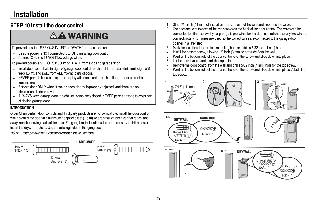
19 Installation STEP 10 Install the door control To preventpossible SERIOUS INJURY or DEATH from electrocution: l Be sure power is NOT connected BEFORE installing door control. l ConnectONLY to 12 VOLT low voltage wires. To preventpossible SERIOUS INJURY or DEATH from a closing garage door: l Install door control within sightofgarage door,outofreach ofchildren ata minimum heightof5 feet(1.5 m),and away from ALL moving parts ofdoor. l NEVER permitchildren to operate or play with door control push buttons or remote control transmitters. l Activate door ONLY when itcan be seen clearly,is properly adjusted,and there are no obstructions to door travel. l ALWAYS keep garage door in sightuntil completely closed.NEVER permitanyone to cross path ofclosing garage door.
Introduction
Older Chamberlain door controls and third party products are notcompatible.Install the door control within sightofthe door ata minimum heightof5 feet(1.5 m) where small children cannotreach,and away from the moving parts ofthe door.For gang box installations itis notnecessary to drill holes or install the drywall anchors.Use the existing holes in the gang box. NOTE: Your productmay look differentthan the illustrations.Hardware
Screw 6ABx1" (2) Drywall Anchors (2) Screw 6-32x1" (2)Drywall
Gang Box
6ABx1" 6-32x1" Drywall Anchor 4-5 6 6-32x1"Gang Box
8Drywall
6ABx1" Drywall Anchor 7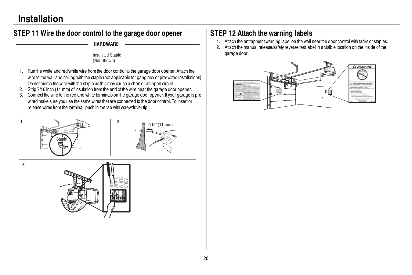
20 Installation STEP 11 Wire the door control to the garage door opener
Hardware
Insulated Staple (Not Shown)Red
White
White
Grey
7/16" (11 mm) 2 3 1 Staple STEP 12 Attach the warning labels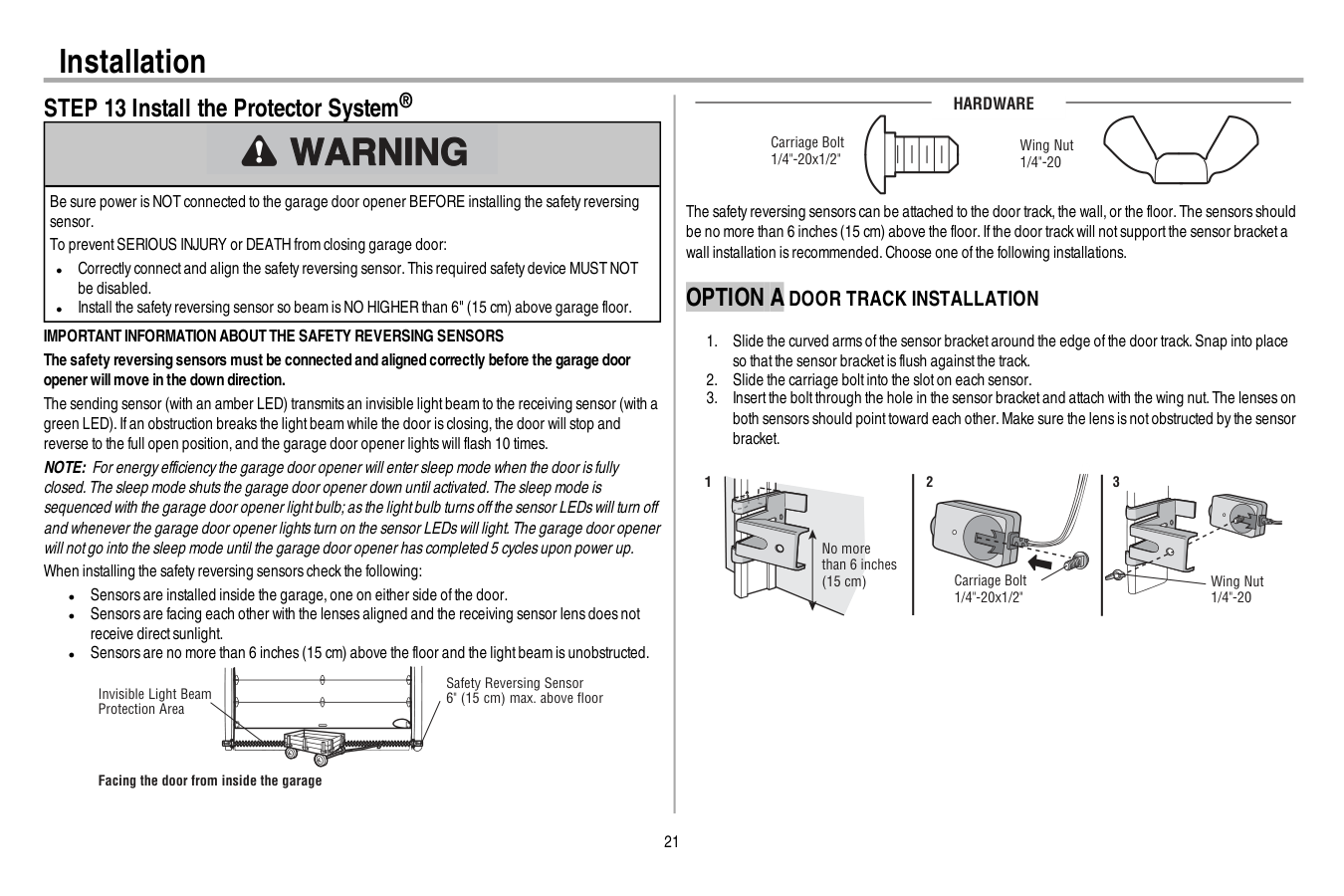
21 Installation STEP 13 Install the Protector System® Be sure power is NOT connected to the garage door opener BEFORE installing the safety reversing sensor. To preventSERIOUS INJURY or DEATH from closing garage door: l Correctly connectand align the safety reversing sensor.This required safety device MUST NOT be disabled. l Install the safety reversing sensor so beam is NO HIGHER than 6" (15 cm) above garage floor.
Important Information About The Safety Reversing Sensors
The safety reversing sensors must be connected and aligned correctly before the garage door openerwillmove in the down direction. The sending sensor (with an amber LED) transmits an invisible lightbeam to the receiving sensor (with a green LED).Ifan obstruction breaks the lightbeam while the door is closing,the door will stop and reverse to the full open position,and the garage door opener lights will flash 10 times. NOTE: For energy efficiency the garage door opener will enter sleep mode when the door is fully closed.The sleep mode shuts the garage door opener down until activated.The sleep mode is sequenced with the garage door opener lightbulb;as the lightbulb turns offthe sensor LEDs will turn off and whenever the garage door opener lights turn on the sensor LEDs will light.The garage door opener will notgo into the sleep mode until the garage door opener has completed 5 cycles upon power up. When installing the safety reversing sensors check the following: l Sensors are installed inside the garage,one on either side ofthe door. l Sensors are facing each other with the lenses aligned and the receiving sensor lens does not receive directsunlight. l Sensors are no more than 6 inches (15 cm) above the floor and the lightbeam is unobstructed. Safety Reversing Sensor 6" (15 cm) max. above floor Invisible Light Beam Protection Area Facing the door from inside the garageHardware
Carriage Bolt 1/4"-20x1/2" Wing Nut 1/4"-20 The safety reversing sensors can be attached to the door track,the wall,or the floor.The sensors should be no more than 6 inches (15 cm) above the floor.Ifthe door track will notsupportthe sensor bracketa wall installation is recommended.Choose one ofthe following installations.Option A Door Track Installation
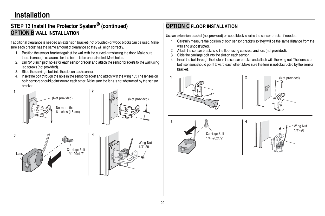
22 Installation STEP 13 Install the Protector System® (continued)
Option B Wall Installation
Ifadditional clearance is needed an extension bracket(notprovided) or wood blocks can be used.Make sure each brackethas the same amountofclearance so they will align correctly.Option C Floor Installation
Use an extension bracket(notprovided) or wood block to raise the sensor bracketifneeded.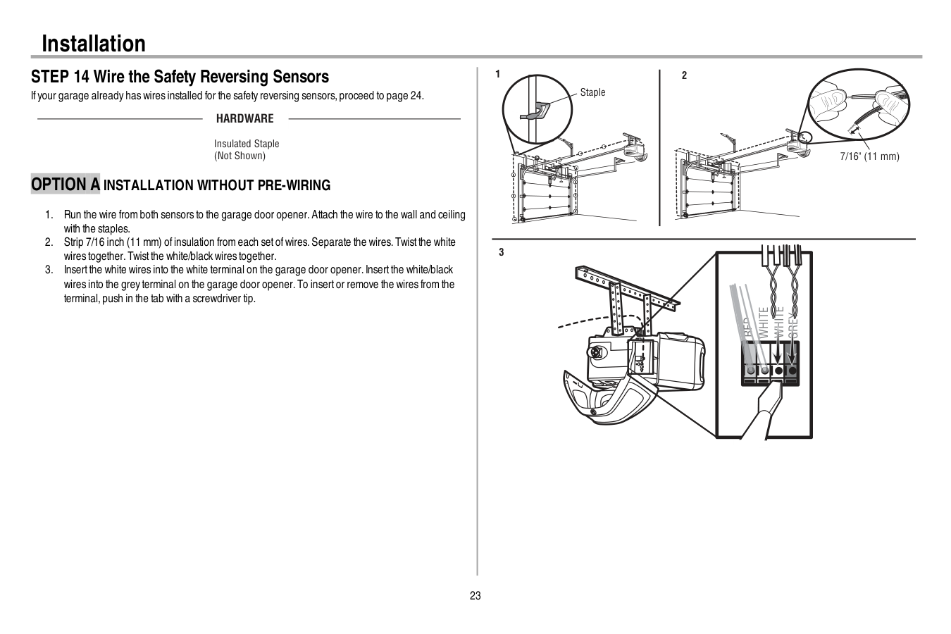
23 Installation STEP 14 Wire the Safety Reversing Sensors Ifyour garage already has wires installed for the safety reversing sensors,proceed to page 24.
Hardware
Insulated Staple (Not Shown)Option A Installation Without Pre-Wiring
White
White
Grey
Red
1 2 3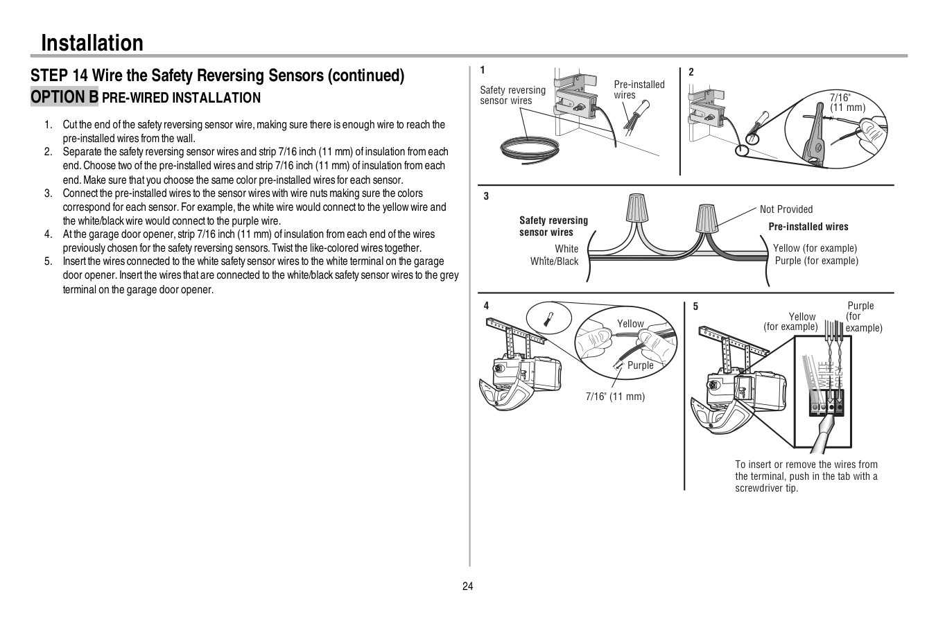
24 Installation STEP 14 Wire the Safety Reversing Sensors (continued)
Option B Pre-Wired Installation
White
White
Red
Grey
Purple (for example) Yellow (for example) To insert or remove the wires from the terminal, push in the tab with a screwdriver tip. 5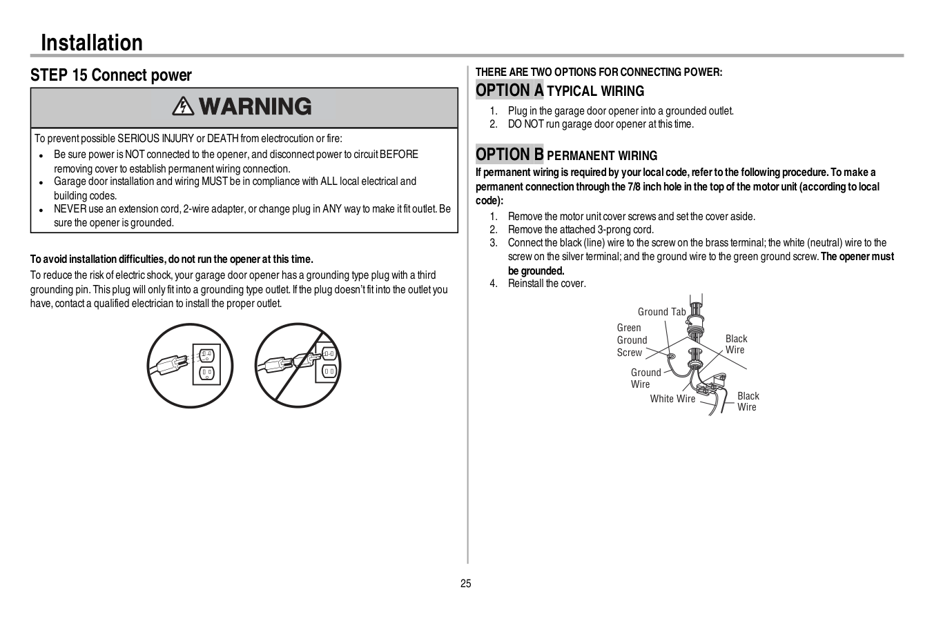
25 Installation STEP 15 Connect power To preventpossible SERIOUS INJURY or DEATH from electrocution or fire: l Be sure power is NOT connected to the opener,and disconnectpower to circuitBEFORE removing cover to establish permanentwiring connection. l Garage door installation and wiring MUST be in compliance with ALL local electrical and building codes. l NEVER use an extension cord,2-wire adapter,or change plug in ANY way to make itfitoutlet.Be sure the opener is grounded. To avoid installation difficulties,do not run the openerat this time. To reduce the risk ofelectric shock,your garage door opener has a grounding type plug with a third grounding pin.This plug will only fitinto a grounding type outlet.Ifthe plug doesn’tfitinto the outletyou have,contacta qualified electrician to install the proper outlet.
There Are Two Options For Connecting Power:
Option A Typical Wiring
Option B Permanent Wiring
If permanent wiring is required by yourlocalcode,referto the following procedure.To make a permanent connection through the 7/8 inch hole in the top of the motorunit (according to local code):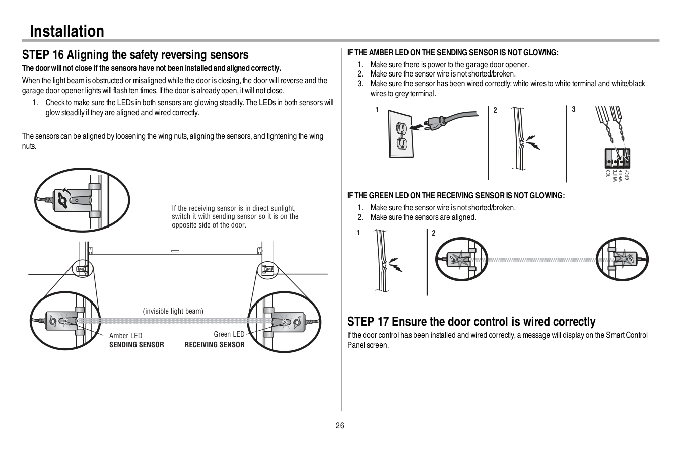
26 Installation STEP 16 Aligning the safety reversing sensors The doorwillnot close if the sensors have not been installed and aligned correctly. When the lightbeam is obstructed or misaligned while the door is closing,the door will reverse and the garage door opener lights will flash ten times.Ifthe door is already open,itwill notclose.
Sending Sensor
Receiving Sensor
If The Amber Led On The Sending Sensor Is Not Glowing:
Red
White
White
Grey
3 2 1If The Green Led On The Receiving Sensor Is Not Glowing:
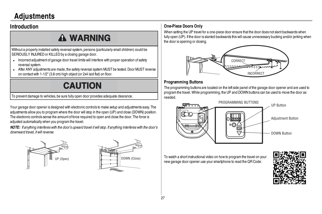
27 Adjustments Introduction Withouta properly installed safety reversal system,persons (particularly small children) could be SERIOUSLY INJURED or KILLED by a closing garage door. l Incorrectadjustmentofgarage door travel limits will interfere with proper operation ofsafety reversal system. l After ANY adjustments are made,the safety reversal system MUST be tested.Door MUST reverse on contactwith 1-1/2" (3.8 cm) high object(or 2x4 laid flat) on floor. To preventdamage to vehicles,be sure fully open door provides adequate clearance. Your garage door opener is designed with electronic controls to make setup and adjustments easy.The adjustments allow you to program where the door will stop in the open (UP) and close (DOWN) position. The electronic controls sense the amountofforce required to open and close the door.The force is adjusted automatically when you program the travel. NOTE: Ifanything interferes with the door’s upward travel itwill stop.Ifanything interferes with the door’s downward travel,itwill reverse. UP (Open) DOWN (Close) One-Piece Doors Only When setting the UP travel for a one-piece door ensure thatthe door does notslantbackwards when fully open (UP).Ifthe door is slanted backwards this will cause unnecessary bucking and/or jerking when the door is opening or closing.
Correct
Incorrect
Programming Buttons The programming buttons are located on the leftside panel ofthe garage door opener and are used to program the travel.While programming,the UP and DOWN buttons can be used to move the door as needed. UP Button Adjustment Button DOWN ButtonProgramming Buttons
To watch a shortinstructional video on how to program the travel on your new garage door opener use your smartphone to read the QR Code: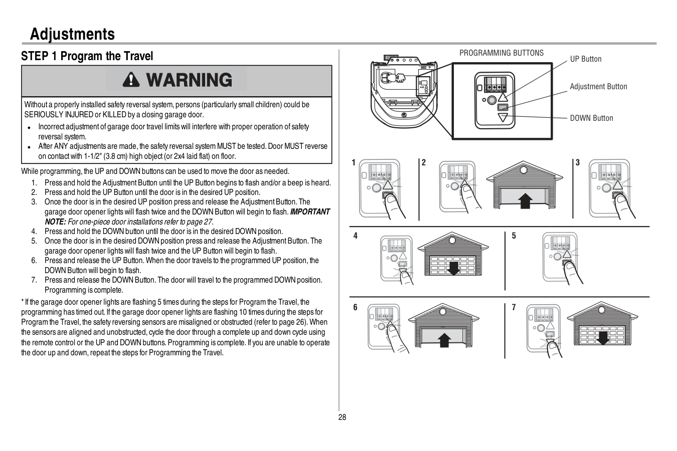
28 Adjustments STEP 1 Program the Travel Withouta properly installed safety reversal system,persons (particularly small children) could be SERIOUSLY INJURED or KILLED by a closing garage door. l Incorrectadjustmentofgarage door travel limits will interfere with proper operation ofsafety reversal system. l After ANY adjustments are made,the safety reversal system MUST be tested.Door MUST reverse on contactwith 1-1/2" (3.8 cm) high object(or 2x4 laid flat) on floor. While programming,the UP and DOWN buttons can be used to move the door as needed.
Programming Buttons
1 2 3 4 5 6 7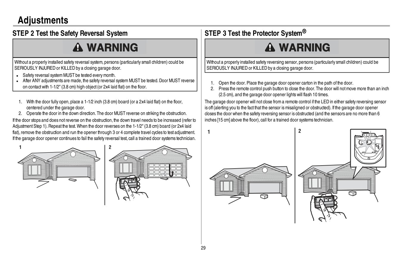
29 Adjustments STEP 2 Test the Safety Reversal System Withouta properly installed safety reversal system,persons (particularly small children) could be SERIOUSLY INJURED or KILLED by a closing garage door. l Safety reversal system MUST be tested every month. l After ANY adjustments are made,the safety reversal system MUST be tested.Door MUST reverse on contactwith 1-1/2" (3.8 cm) high object(or 2x4 laid flat) on the floor.
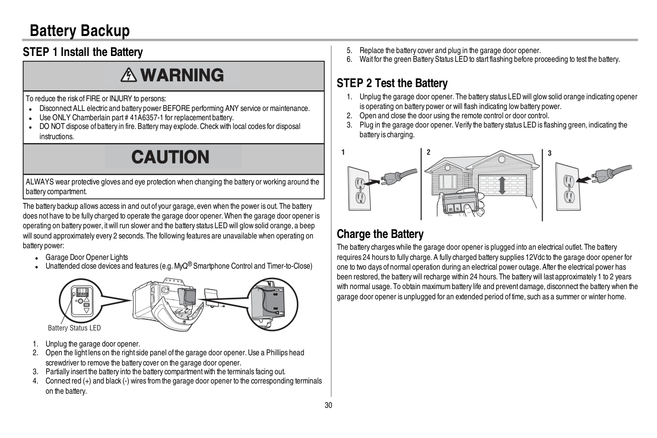
30 Battery Backup STEP 1 Install the Battery To reduce the risk ofFIRE or INJURY to persons: l DisconnectALL electric and battery power BEFORE performing ANY service or maintenance. l Use ONLY Chamberlain part# 41A6357-1 for replacementbattery. l DO NOT dispose ofbattery in fire.Battery may explode.Check with local codes for disposal instructions. ALWAYS wear protective gloves and eye protection when changing the battery or working around the battery compartment. The battery backup allows access in and outofyour garage,even when the power is out.The battery does nothave to be fully charged to operate the garage door opener.When the garage door opener is operating on battery power,itwill run slower and the battery status LED will glow solid orange,a beep will sound approximately every 2 seconds.The following features are unavailable when operating on battery power: l Garage Door Opener Lights l Unattended close devices and features (e.g.MyQ® Smartphone Control and Timer-to-Close) Battery Status LED

31
Important Safety Instructions
To reduce the risk of SEVERE INJURY or DEATH:Read And Follow All Warnings And Instructions.
No One Should Go Under A Stopped,Partially Opened Door.
Death.
16. Save These Instructions.
Operation
32 Operation Using your Garage Door Opener l The garage door opener can be activated with a wall-mounted door control,remote control, wireless keyless entry,MyQ® Smartphone Control app or MyQ® Garage Door Monitor.When the door is closed and the garage door opener is activated the door will open.Ifthe door senses an obstruction or is interrupted while opening the door will stop.When the door is in any position other than closed and the garage door opener is activated the door will close.Ifthe garage door opener senses an obstruction while closing,the door will reverse.Ifthe obstruction interrupts the sensor beam the garage door opener lights will blink 10 times.Ifthe door is fully open,and the safety reversing sensors are notinstalled,or are misaligned,the door will notclose from a remote control,TTC,or the MyQ® Smartphone Control app.However,you can close the door by holding the button on the door control or the ENTER button on the keyless entry until the door is fully closed. l The garage door opener lightbulbs will turn on when the opener is initially plugged in;power is restored after interruption,or when the garage door opener is activated.The lights will turn off automatically after 4-1/2 minutes.The lights will turn on when someone enters through the open garage door and the safety reversing sensor infrared beam is obstructed,see page 33.Use an incandescentA19 lightbulb (100 wattmaximum) or for maximum energy efficiency a 26W (100W equivalent) compactfluorescentlight(CFL) bulb.NOTE: Do notuse halogen,shortneck,or specialty lightbulbs as these may overheatthe end panel or lightsocket.Do notuse LED bulbs as they may reduce the range or performance ofyour remote controls. To Open the Door Manually To preventpossible SERIOUS INJURY or DEATH from a falling garage door: l Ifpossible,use emergency release handle to disengage trolley ONLY when garage door is CLOSED.Weak or broken springs or unbalanced door could resultin an open door falling rapidly and/or unexpectedly. l NEVER use emergency release handle unless garage doorway is clear ofpersons and obstructions. l NEVER use handle to pull door open or closed.Ifrope knotbecomes untied,you could fall.
Disconnect The Trolley
To Reconnect The Trolley

33 Operation Door Control SYNCHRONIZE THE DOOR CONTROL: To synchronize the door control to the garage door opener, press the push bar until the garage door opener activates (itmay take up to 3 presses).Testthe door control by pressing the push bar;each press ofthe push bar will activate the garage door opener. Push Bar LIGHT Button Motion Sensor Navigation Buttons Screen PUSH BAR: Press the push bar to open or close the door. LIGHT BUTTON: Press the LIGHT button to turn the garage door opener lights on or off.When the lights are turned on they will stay on until the LIGHT button is pressed again,or until the garage door opener is activated.Once the garage door opener is activated the lights will turn offafter the specified period of time (the factory defaultis 4-1/2 minutes).The LIGHT button will notcontrol the lights when the door is in motion.The LightFeature will turn on the lighton the garage door opener when someone enters through the open garage door and the safety reversing sensor infrared beam is obstructed. MOTION SENSOR: The motion sensor automatically turns on the garage door opener lights when motion is detected.The lights come on for the setperiod oftime,and then shutoff.Ifusing the garage door opener lightas a work lightdisable the motion sensor,otherwise the lights may turn offautomatically ifyou are beyond the range ofthe motion sensor. NAVIGATION AND SCREEN: The screen displays the time,temperature,and currentbattery charge (if applicable) until the menu button is pressed,and then itwill display the menu options.Ifthere is a problem with the garage doors opener the screen will display an error code (diagnostic code,see page 37).The features on the door control can be programmed through a series ofmenus on the screen.Use the navigation buttons to scroll through the menus and make selections.
Menu Options
CLOCK SETUP: Setthe time;choose 12 or 24 hour clock and show/hide clock. TEMPERATURE: Display the temperature in Fahrenheitor Celsius and show/hide the temperature. LANGUAGE: SelectEnglish,Spanish or French. CONTRAST ADJUST: Adjustthe screen contrast.Light Settings:
To change the amountoftime the lights stay on:
34 Operation
Menu Options (Continued)
TIMER-TO-CLOSE (TTC) (Factory default is set to off): The Timer-to-Close feature automatically closes the door after a specified time period and can be adjusted using the door control.DO NOT enable TTC ifoperating a one-piece door.TTC is to be used ONLY with sectional doors.The garage door opener will beep and the lights will flash before closing the door.The TTC feature will deactivate ifthe garage door encounters an obstruction twice;or the safety reversing sensors are incorrectly installed. The garage door will reverse open and WILL NOT close until the obstructions are clear or the safety reversing sensors are correctly installed.When the obstruction has been cleared or the safety reversing sensors have been aligned,the door will close when the garage door opener is activated.TTC WILL NOT work ifthe garage door opener is operating by battery power or ifthe safety reversing sensors are misaligned.This feature is NOT intended to be the primary method ofclosing the door.A keyless entry should be installed in the eventofan accidental lock outwhen using this feature. To turn TTC on or offor to setthe TTC time interval:
35 Operation Remote Control and Keyless Entry Yourremote controlhas been programmed at the factory to operate with yourgarage dooropener, randomly accessing over100 billion new codes with each use.Your garage door opener can be programmed with up to 8 remote controls,1 keyless entry and 2 Security+ 2.0™door controls.Older Chamberlain remote controls are NOT compatible,see page 39 for compatible accessories. Programming can be done through the door control or the learn button on the garage door opener.To program additional accessories refer to the instructions provided with the accessory or visit www.chamberlain.com.Ifyour vehicle is equipped with a Homelink®,you may require an external adapter depending on the make,model,and year ofyour vehicle.Visitwww.homelink.com for additional information.
To Add, Reprogram, Or Change A Remote Control/Keyless Entry Pin
Using The Smart Control Panel
Or
Pin
? ? ? ? 4 Press to continue. Press to continue. To Erase the MemoryErase All Remote Controls And Keyless Entries
Garage Door Opener
Network

36 Maintenance Maintenance Schedule
Every Month
l Manually operate door.Ifitis unbalanced or binding,call a trained door systems technician. l Check to be sure door opens and closes fully.Adjustifnecessary,see page 27. l Testthe safety reversal system.Adjustifnecessary,see page 27.Every Year
l Oil door rollers,bearings and hinges.The garage door opener does notrequire additional lubrication.Do notgrease the door tracks. l Testthe battery backup and consider replacing the battery to ensure the garage door opener will operate during an electrical power outage,see page 30 to testthe battery backup. The Remote Control Battery To preventpossible SERIOUS INJURY or DEATH: l NEVER allow small children near batteries. l Ifbattery is swallowed,immediately notify doctor. To reduce risk offire,explosion or chemical burn: l Replace ONLY with 3V CR2032 coin batteries. l DO NOT recharge,disassemble,heatabove 212°F (100°C) or incinerate. The 3V CR2032 lithium battery should produce power for up to 3 years.Ifthe battery is low,the remote control’s LED will notflash when the button is pressed. To replace battery,pry open the case firstin the middle (1), then ateach side (2 and 3) with the visor clip.Replace the batteries with only 3V CR2032 coin cell batteries.Insert battery positive side up.Dispose ofold batteries properly. 1 2 3 NOTICE:To complywith FCC and/orIndustryCanada (IC)rules,adjustmentormodificationsofthistransceiverare prohibited.THEREArenouser Serviceableparts.
Thisdevice complieswith Part15 ofthe FCC rulesand IC RSS-210.Operation issubjectto the following two conditions:(1)thisdevice maynotcause harmfulinterference,and (2)thisdevice mustacceptanyinterference received,including interference thatmaycause undesired operation. Thisdevice mustbe installed in a waywhere a minimum8"(20cm)distance ismaintained between users/bystandersand device. AVIS:Lesrèglesde la FCC et/ou d’Industrie Canada (IC)interdisenttoutajustementou toute modification de ce récepteur.IL N’EXISTEAucunepiècesusceptibled’Êtreentretenuepar L’Utilisateur.
Cetappareilestconforme auxdispositionsde la partie 15 du règlementde la FCC etde l'norme IC RSS-210.Son utilisation estassujettie auxdeuxconditoinssuivantes:(1)ce dispositifne peutcauserdesinterférencesnuisibles,et(2)ce dispositifdoitacceptertoute interférence recue,ycomprisune interférence pouvantcauserun fonctionnementnon souhaité. Cetappareildoitêtre installé de manière à laisserune distance d’au moins20 cm(8 po)entre celui-cietl’utilisateurou toute personne.
37 Diagnostic Chart Your garage door opener is programmed with self-diagnostic capabilities.The UP and DOWN arrows on the garage door opener flash the diagnostic codes.
Diagnostic Code
Symptom
Solution
Up Arrow Flash(es) Down Arrow Flash(es) 1 1 The garage door opener will notclose and the lightbulbs flash. Safety sensors are notinstalled,connected,or wires may be cut.Inspectsensor wires for a disconnected or cutwire. 1 2 The garage door opener will notclose and the lightbulbs flash. There is a shortor reversed wire for the safety sensors.Inspectsafety sensor wire atall staple and connection points,replace wire or correctas needed. 1 3 The door control will notfunction. The wires for the door control are shorted or the door control is faulty.Inspectdoor control wires atall staple and connection points,replace wire or correctas needed. 1 4 The garage door opener will notclose and the lightbulbs flash. Safety sensors are misaligned or were momentarily obstructed.Realign both sensors to ensure both LEDs are steady and notflickering.Make sure nothing is hanging or mounted on the door thatwould interruptthe sensor’s path while closing. 1 5 Door moves 6-8" stops or reverses. Manually open and close the door.Check for binding or obstructions,such as a broken spring or door lock,correctas needed.Check wiring connections attravel module and atthe logic board.Replace travel module ifnecessary. No movement,only a single click. Manually open and close the door.Check for binding or obstructions,such as a broken spring or door lock,correctas needed.Replace logic board ifnecessary. Opener hums for 1-2 seconds no movement. Manually open and close the door.Check for binding or obstructions,such as a broken spring or door lock,correctas needed.Replace motor ifnecessary. 1 6 Door coasts after ithas come to a complete stop. Program travel to coasting position or have door balanced by a trained door systems technician. 2 1-5 No movement,or sound. Replace logic board. 3 2 Unable to setthe travel or retain position. Check travel module for proper assembly,replace ifnecessary. 3 3 The battery status LED is constantly flashing green. Battery backup charging circuiterror,replace the logic board. 4 1-4 Door is moving stops or reverses. Manually open and close the door.Check for binding or obstructions,such as a broken spring or door lock,correctas needed.Ifthe door is binding or sticking contacta trained door systems technician.Ifdoor is notbinding or sticking attemptto reprogram travel (refer to page 27). Troubleshooting
38
Diagnostic Code
Symptom
Solution
Up Arrow Flash(es) Down Arrow Flash(es) 4 5 Opener runs approximately 6-8",stops and reverses. Communication error to travel module.Check travel module connections,replace travel module if necessary. 4 6 The garage door opener will notclose and the lightbulbs flash. Safety sensors are misaligned or were momentarily obstructed.Realign both sensors to ensure both LEDs are steady and notflickering.Make sure nothing is hanging or mounted on the door thatwould interruptthe sensor’s path while closing. The garage dooropenercan beep forseveralreasons: l Operating on battery power or the 12 Vdc battery needs to be replaced,see page 30. l Garage door opener has been activated through a device or feature such as Timer-to-Close or garage door monitor,see page 32. My remote controlwillnot activate the garage door: l Verify the lock feature is notactivated on the door control. l Reprogram the remote control. l Ifthe remote control will still notactivate the door check the diagnostic codes to ensure the garage door opener is working properly. My doorwillnot close and the light bulbs blink on my motorunit: The safety reversing sensor mustbe connected and aligned correctly before the garage door opener will move in the down direction. l Verify the safety sensors are properly installed,aligned and free ofany obstructions. My garage dooropenerlight(s) willnot turn off when the dooris open: The garage door opener is equipped with a feature thatturns the lighton when the safety reversing sensors have been obstructed or when the motion sensor on the door control detects movementin the garage.These features can be disabled using the door control,see page 33. My neighbor’s remote controlopens my garage door: Erase the memory from your garage door opener and reprogram the remote control(s). The LEDs on the doorcontrolblink: Ifyou have a SmartControl Panel installed and the TTC is setto a custom time,press the ON button on the Premium Motion-Detecting Control Panel to setthe time properly. My vehicle's Homelink® is not programming to my garage dooropener: Depending on the make,model,and year ofyour vehicle an external adapter may be required.Visit www.homelink.com for additional information. Wi-Fitroubleshooting Ifyour black adjustmentbutton is notsolid green go to wifihelp.chamberlain.com. Green battery status LED - Allsystems are normal: l A solid green LED lightindicates the battery is fully charged. l A flashing green LED indicates the battery is being charged. Orange battery status LED - The garage dooropenerhas lost powerand is in battery backup mode: l A solid orange LED with beep,sounding approximately every 2 seconds,indicates the garage door opener is operating on battery power. l A flashing orange LED with beep,sounding every 30 seconds,indicates the battery is low. Red battery status LED - The garage dooropener's 12V battery needs to be replaced: l A solid red LED with beep,sounding every 30 seconds,indicates the 12V battery will no longer hold a charge and needs to be replaced.Please call for replacementbattery to allow your system to operate during a power outage. Battery Status LED Troubleshooting
39 Accessories
Cllp1
953Ev
Clss1
Laser Parking Assistant: Park in the right spot every time! A laser beam is activated by your garage door opener and projected on to the dashboard of your vehicle to guide perfect parking. Remote Control: Works with ALL Chamberlain openers from 1993-present. MyQ® compatible. Includes visor clip. System Surge Protector: The Garage Door Opener Surge Protector is designed to protect Chamberlain garage door openers against damage from lightning and power surges. Easy to install.Agdmev
MyQ® Garage Door Monitor: Monitor open/closed status for up to 4 MyQ® compatible garage door openers or gate operators and close them from anywhere in the home.956Ev
Keychain Remote Control: Works with ALL Chamberlain openers from 1993-present. MyQ® compatible. With key ring.940Ev
Wireless Keypad: For use outside of the home to enable access to the garage using a 4-digit PIN. Works with ALL Chamberlain openers from 1993-present. MyQ® compatible.Pilcev
MyQ® Remote Lamp Control: Monitor and control this plug in lamp switch with the MyQ® Smartphone App.Wslcev
MyQ® Interior/Exterior Light Switch Monitor and control this wall light switch with the MyQ® Smartphone App. Extension Brackets: (Optional) For safety reversing sensor installation onto the wall or fl oor.041A5281-1
8810Cb
10 Foot (3 m) Rail Extension: To allow a 10 foot (3 m) door to open fully. 8 Foot (2.4 m) Rail Extension: To allow an 8 foot (2.4 m) door to open fully.8808Cb
7702Cb
Outside Quick Release: Required for a garage with NO access door.41A6357-1
Standby Power System Battery: Provides backup power to the garage door opener.Cigbu
MyQ® Accessories MyQ® Internet Gateway: Offers longer range wireless signal than standard Wi-Fi. Plugs into your home router as an optional way to provide MyQ® Smartphone Control for your garage door opener and MyQ® light controls.
40 Warranty
Chamberlain® Limited Warranty
The Chamberlain Group, Inc.® (“Seller”) warrants to the fi rst retail purchaser of this product, for the residence in which this product is originally installed, that it is free from defects in materials and/or workmanship for a specifi c period of time as defi ned below (the “Warranty Period”). The warranty period commences from the date of purchase.Warranty Period
Parts Motor Accessories Belt Battery Backup 5 Years Lifetime 1 year Lifetime 1 year The proper operation of this product is dependent on your compliance with the instructions regarding installation, operation, and maintenance and testing. Failure to comply strictly with those instructions will void this limited warranty in its entirety. If, during the limited warranty period, this product appears to contain a defect covered by this limited warranty, call 1-800- 528-9131, toll free, before dismantling this product. You will be advised of disassembly and shipping instructions when you call. Then send the product or component, pre-paid and insured, as directed to our service center for warranty repair. Please include a brief description of the problem and a dated proof- of-purchase receipt with any product returned for warranty repair. Products returned to Seller for warranty repair, which upon receipt by Seller are confi rmed to be defective and covered by this limited warranty, will be repaired or replaced (at Seller’s sole option) at no cost to you and returned pre-paid. Defective parts will be repaired or replaced with new or factory rebuilt parts at Seller’s sole option. [You are responsible for any costs incurred in removing and/or reinstalling the product or any component .] ALL IMPLIED WARRANTIES FOR THE PRODUCT, INCLUDING BUT NOT LIMITED TO ANY IMPLIEDWarranties Of Merchantability And Fitness For A Particular Purpose, Are Limited
In Duration To The Applicable Limited Warranty Period Set Forth Above For The
Related Component(S), And No Implied Warranties Will Exist Or Apply After Such
PERIOD. Some States and Provinces do not allow limitations on how long an implied warranty lasts, so the above limitation may not apply to you. THIS LIMITED WARRANTY DOES NOT COVERNon-Defect Damage, Damage Caused By Improper Installation, Operation Or Care
(Including, But Not Limited To Abuse, Misuse, Failure To Provide Reasonable And
NECESSARY MAINTENANCE, UNAUTHORIZED REPAIRS OR ANY ALTERATIONS TO THIS PRODUCT),Labor Charges For Reinstalling A Repaired Or Replaced Unit, Replacement Of
CONSUMABLE ITEMS (E.G., BATTERIES IN REMOTE CONTROL TRANSMITTERS AND LIGHT BULBS), OR UNITS INSTALLED FOR NON-RESIDENTIAL USE. THIS LIMITED WARRANTY DOES NOT COVERAny Problems With, Or Relating To, The Garage Door Or Garage Door Hardware,
Including But Not Limited To The Door Springs, Door Rollers, Door Alignment
Or Hinges. This Limited Warranty Also Does Not Cover Any Problems Caused By
Interference. Under No Circumstances Shall Seller Be Liable For Consequential,
INCIDENTAL OR SPECIAL DAMAGES ARISING IN CONNECTION WITH USE, OR INABILITY TO USE, THIS PRODUCT. IN NO EVENT SHALL SELLER’S LIABILITY FOR BREACH OF WARRANTY, BREACH OF CONTRACT, NEGLIGENCE OR STRICT LIABILITY EXCEED THE COST OF THE PRODUCT COVERED HEREBY. NO PERSON IS AUTHORIZED TO ASSUME FOR US ANY OTHER LIABILITY IN CONNECTIONWith The Sale Of This Product.
Some states and provinces do not allow the exclusion or limitation of consequential, incidental or special damages, so the above limitation or exclusion may not apply to you. This limited warranty gives you specifi c legal rights, and you may also have other rights, which vary from state to state and province to province. Contact Information For installation and service information, please visit: www.chamberlain.com/parts-and-support If you are ordering a repair part please have the following information: part number, part name, and model number. Address repair parts orders to: The Chamberlain Group, Inc. 6050 S. Country Club Road Tucson, AZ 85706 Register your new garage door opener at www.prodregister.com/chamberlain Stop!
This garage door opener WILL NOT work until the safety reversing sensors are properly installed and aligned.
41 Repair Parts Rail Assembly Parts Accessories Installation Parts 1 3 2 4 6 5 1 2
Notice
1 3 4 2 5 6 7 8 9 10 11 Description Part Number 1 Belt41A5250
2 Pulley144C54
3 Master Link4A1008
4 Rail41A5665
5 Trolley Assembly41C5141-2
6 “U” Bracket12D598-1
Not Shown Wear Pads183A163
Hardware Bag041A7920-2
Description Part Number 1 Smart Control Panel®41A7305-1
2 Remote Control953Estd
Description Part Number 1 Curved Door Arm178B35
2 Door Bracket with Clevis Pin and Fastener41A5047-1
3 Emergency Release Rope and Handle41A2828
4 Header Bracket with Clevis Pin and Fastener41A5047-2
5 Remote Control Visor Clip29B137
6 Safety Sensor Bracket041A5266-3
7 Safety Sensor Kit Receiving and sending sensors with wire41A5034
8 Straight Door Arm178B34
9 White and Red/White Wire41B4494-1
10 3V CR2030 Lithium Battery10A20
11 Hanging Brackets12B776
Not Shown Owner’s Manual114A4763

42 1 7 5 3 4 3 9 6 8 2 4 10 Repair Parts Description Part Number 1 Sprocket and Sprocket Cover with Screws
041C0589-2
2 End Panel with light socket041D7639
3 Light Lens Model WD1000WF Model HD950WF Model LW9000WF041D7570
041D7572
041D7571
4 Light Socket041C0279
5 Transformer041D0277-1
6 Cover041D0614-23
7 Motor with Travel Module041D1739-1
8 End Panel for Receiver Logic Board with light socket041D7638
9 Receiver Logic Board050Dctwf
10 Travel Module041A7114-7
Garage Door Opener Parts
© 2014, The Chamberlain Group, Inc.
All Rights Reserved