
Dixell XR06CX Temperature Controller
Ask AI
— answers from the official manualAnswers from the official manual.
Common questions
Common Questions
35 totalHow do I change the temperature setpoint on the XR06CX?
Press the SET key for more than 2 seconds to enter setpoint change mode, then the setpoint value will display with the °C or °F LED blinking. Use the up or down arrow keys to adjust the value, and press SET again or wait 10 seconds to save the new setpoint.
What does the 'P1' alarm message mean and how do I fix it?
The 'P1' message indicates a room probe (thermostat) failure. When this alarm occurs, the compressor output will operate according to the 'Cy' and 'Cn' parameters. Check the probe connections before replacing the probe, as the alarm should automatically stop within seconds after the probe returns to normal operation.
How do I start a manual defrost cycle?
Press the DEF key for more than 2 seconds to start a manual defrost. The defrost will begin if the conditions allow it.
What is the anti-short cycle delay and what is the default setting?
The anti-short cycle delay (AC parameter) is the minimum interval between the compressor stop and the following restart, which prevents the compressor from cycling too quickly. The default setting is 1 minute, and it can be adjusted from 0 to 50 minutes.
How do I lock the keyboard to prevent accidental changes?
Keep the Aux and down arrow keys pressed together for more than 3 seconds until the 'OF' message is displayed. The keyboard will then be locked, and pressing any key for more than 3 seconds will display the 'OF' message.
How do I use the Hot Key to copy settings from one controller to another?
To upload settings to the Hot Key, turn the controller ON, insert the Hot Key, press the down arrow key until 'uP' appears followed by a flashing 'Ed', then press SET to confirm. To download to another controller, turn it OFF, insert the programmed Hot Key, then turn it ON — the parameters will automatically load and the controller restarts after 10 seconds. An 'Er' message indicates a failed transfer. (Page 2)
Show 29 more questions
What are the operating environment and installation requirements for the XR06CX?
What are the four fan operating modes and what is the default setting?
How do I start a manual defrost on the Xr06cx?
How do I change the setpoint on the Xr06cx?
How do I lock and unlock the keyboard to prevent accidental changes?
What are the two available defrost modes and how do I configure them?
What happens when the 'CA' serious alarm is triggered?
How do I access the hidden menu to view all parameters?
How do I program multiple controllers quickly using the Hot Key?
What are the operating and storage temperature limits for the Xr06cx?
What safety precautions should I follow before performing maintenance on the Xr06cx?
How can I lock the keyboard on my Dixell Xr06cx?
What should I do if there's a thermostat probe failure?
How do I reset the unit to default settings?
What is the function of the digital input when set as a door switch?
What does fan operating mode FC=on do?
How can I start a manual defrost?
Where should probes be installed on the Dixell Xr06cx?
When there is a serious alarm (IF=BA), what happens?
How do I change the differential range?
How do I change the unit's measurement from Celsius to Fahrenheit or vice versa?
What do the alarm codes 'P1' and 'P2' mean on the display?
What happens during a 'CA' serious alarm and how do I clear it?
What are the safety precautions I should follow before performing maintenance?
What are the different fan operating modes available on the XR06CX?
How do I program settings using the HOTKEY?
What does the 'P2' alarm message indicate?
What is the maximum current allowed on the compressor relay?
How should I mount the temperature probes to ensure accurate operation?
Full Manual
3 pages
|5.1 FANS AND DIGITAL INPUT| |---|
|DIGITAL CONTROLLER WITH DEFROST AND FANS MANAGEMENT XR06CX
| |---|
When the digital input is configured as door switch iF=do, fans and compressor status depends on the dC parameter value:
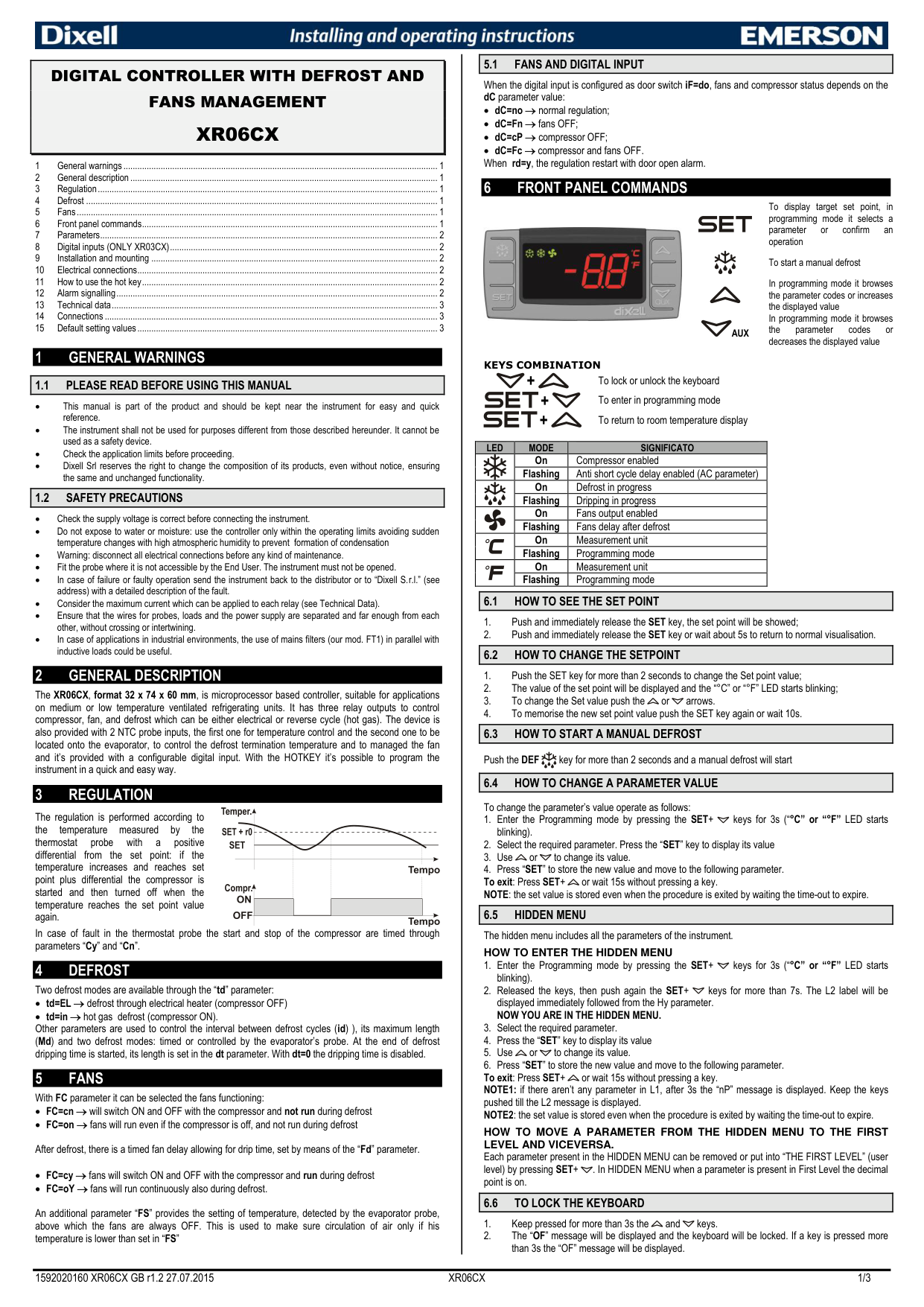
6 FRONT PANEL COMMANDS
To display target set point, in programming mode it selects a parameter or confirm an operation

To start a manual defrost
In programming mode it browses the parameter codes or increases the displayed value
In programming mode it browses the parameter codes or decreases the displayed value
AUX
1 GENERAL WARNINGS
KEYS COMBINATION
+ To lock or unlock the keyboard + To enter in programming mode
|1.1 PLEASE READ BEFORE USING THIS MANUAL| |---|
|1.2 SAFETY PRECAUTIONS| |---|
+ To return to room temperature display
|LED|MODE|SIGNIFICATO| |---|---|---| | |On|Compressor enabled| | |Flashing|Anti short cycle delay enabled (AC parameter)| | |On|Defrost in progress| | |Flashing|Dripping in progress| | |On|Fans output enabled| | |Flashing|Fans delay after defrost| | |On|Measurement unit| | |Flashing|Programming mode| | |On|Measurement unit| | |Flashing|Programming mode|
|6.1 HOW TO SEE THE SET POINT| |---|
|6.2 HOW TO CHANGE THE SETPOINT| |---|
2 GENERAL DESCRIPTION
The XR06CX, format 32 x 74 x 60 mm, is microprocessor based controller, suitable for applications on medium or low temperature ventilated refrigerating units. It has three relay outputs to control compressor, fan, and defrost which can be either electrical or reverse cycle (hot gas). The device is also provided with 2 NTC probe inputs, the first one for temperature control and the second one to be located onto the evaporator, to control the defrost termination temperature and to managed the fan and it’s provided with a configurable digital input. With the HOTKEY it’s possible to program the instrument in a quick and easy way.
|6.3 HOW TO START A MANUAL DEFROST| |---|
Push the DEF key for more than 2 seconds and a manual defrost will start
|6.4 HOW TO CHANGE A PARAMETER VALUE| |---|
3 REGULATION
To change the parameter’s value operate as follows:
The regulation is performed according to the temperature measured by the thermostat probe with a positive differential from the set point: if the temperature increases and reaches set point plus differential the compressor is started and then turned off when the temperature reaches the set point value again.
|6.5 HIDDEN MENU| |---|
In case of fault in the thermostat probe the start and stop of the compressor are timed through parameters “Cy” and “Cn”.
The hidden menu includes all the parameters of the instrument. HOW TO ENTER THE HIDDEN MENU
4 DEFROSTTwo defrost modes are available through the “td” parameter:
###### HOW TO MOVE A PARAMETER FROM THE HIDDEN MENU TO THE FIRST LEVEL AND VICEVERSA.
Each parameter present in the HIDDEN MENU can be removed or put into “THE FIRST LEVEL” (user level) by pressing SET+ . In HIDDEN MENU when a parameter is present in First Level the decimal point is on.
|6.6 TO LOCK THE KEYBOARD| |---|
An additional parameter “FS” provides the setting of temperature, detected by the evaporator probe, above which the fans are always OFF. This is used to make sure circulation of air only if his temperature is lower than set in “FS”
|8.1 DOOR SWITCH (IF=DO)| |---|
It signals the door status and the corresponding relay output status through the “dC” parameter: no = normal (any change); Fn = Fan OFF; CP = Compressor OFF; FC = Compressor and fan OFF. Since the door is opened, after the delay time set through parameter “di”, the door alarm is enabled, the display shows the message “dA” and the regulation restarts if rd = y. The alarm stops as soon as the external digital input is disabled again. With the door open, the high and low temperature alarms are disabled.
|8.2 EXTERNAL ALARM (IF=EA)| |---|
As soon as the digital input is activated the unit will wait for “di” time delay before signalling the “EA” alarm message. The outputs status don’t change. The alarm stops just after the digital input is deactivated.
|8.3 SERIOUS ALARM (IF=BA)| |---|
When the digital input is activated, the unit will wait for “di” delay before signalling the “CA” alarm message. The relay outputs are switched OFF. The alarm will stop as soon as the digital input is deactivated.
|8.4 START DEFROST (IF=DF)| |---|
It starts a defrost if there are the right conditions. After the defrost is finished, the normal regulation will restart only if the digital input is disabled otherwise the instrument will wait until the “Md” safety time is expired.
|8.5 INVERSION OF THE KIND OF ACTION: HEATING - COOLING (IF=HC)| |---|
This function allows to invert the regulation of the controller: from cooling to heating and viceversa.
| | | |---|---| | | |
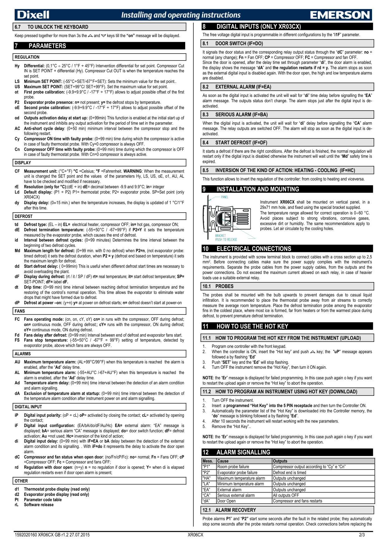
Instrument XR06CX shall be mounted on vertical panel, in a 29x71 mm hole, and fixed using the special bracket supplied.
The temperature range allowed for correct operation is 060 °C. Avoid places subject to strong vibrations, corrosive gases, excessive dirt or humidity. The same recommendations apply to probes. Let air circulate by the cooling holes.
The instrument is provided with screw terminal block to connect cables with a cross section up to 2,5 mm2. Before connecting cables make sure the power supply complies with the instrument’s requirements. Separate the probe cables from the power supply cables, from the outputs and the power connections. Do not exceed the maximum current allowed on each relay, in case of heavier loads use a suitable external relay.
|10.1 PROBES| |---|
The probes shall be mounted with the bulb upwards to prevent damages due to casual liquid infiltration. It is recommended to place the thermostat probe away from air streams to correctly measure the average room temperature. Place the defrost termination probe among the evaporator fins in the coldest place, where most ice is formed, far from heaters or from the warmest place during defrost, to prevent premature defrost termination.
|11.1 HOW TO PROGRAM THE HOT KEY FROM THE INSTRUMENT (UPLOAD)| |---|
NOTE: the “Er” message is displayed for failed programming. In this case push again o key if you want to restart the upload again or remove the “Hot key” to abort the operation.
|11.2 HOW TO PROGRAM AN INSTRUMENT USING HOT KEY (DOWNLOAD)| |---|
NOTE: the “Er” message is displayed for failed programming. In this case push again o key if you want to restart the upload again or remove the “Hot key” to abort the operation.
|6.7 TO UNLOCK THE KEYBOARD| |---|
Keep pressed together for more than 3s the and keys till the “on” message will be displayed. 7 PARAMETERS
|REGULATION| |---|
Hy Differential: (0,1°C 25°C / 1°F ÷ 45°F) Intervention differential for set point. Compressor Cut IN is SET POINT + differential (Hy). Compressor Cut OUT is when the temperature reaches the set point.
LS Minimum SET POINT: (-55°C÷SET/-67°F÷SET): Sets the minimum value for the set point.. US Maximum SET POINT: (SET÷99°C/ SET÷99°F). Set the maximum value for set point. ot First probe calibration: (-9.9÷9.9°C / -17°F ÷ 17°F) allows to adjust possible offset of the first
probe. P2 Evaporator probe presence: n= not present; y= the defrost stops by temperature. oE Second probe calibration: (-9.9÷9.9°C / -17°F ÷ 17°F) allows to adjust possible offset of the
second probe.
od Outputs activation delay at start up: (0÷99min) This function is enabled at the initial start up of the instrument and inhibits any output activation for the period of time set in the parameter. AC Anti-short cycle delay: (0÷50 min) minimum interval between the compressor stop and the
following restart.
Cy Compressor ON time with faulty probe: (0÷99 min) time during which the compressor is active
in case of faulty thermostat probe. With Cy=0 compressor is always OFF.
Cn Compressor OFF time with faulty probe: (0÷99 min) time during which the compressor is OFF
in case of faulty thermostat probe. With Cn=0 compressor is always active.
|DISPLAY| |---|
CF Measurement unit: (°C÷°F) °C =Celsius; °F =Fahrenheit. WARNING: When the measurement unit is changed the SET point and the values of the parameters Hy, LS, US, oE, o1, AU, AL have to be checked and modified if necessary.
rE Resolution (only for °C):(dE ÷ in) dE= decimal between -9.9 and 9.9°C; in= integer Ld Default display: (P1 ÷ P2) P1= thermostat probe; P2= evaporator probe. SP=Set point (only
XR04CX)
dy Display delay: (015 min.) when the temperature increases, the display is updated of 1 °C/1°F
after this time.
|DEFROST| |---|
td Defrost type: (EL – in) EL= electrical heater, compressor OFF; in= hot gas, compressor ON; dE Defrost termination temperature: (-55÷50°C / -67÷99°F) if P2=Y it sets the temperature
measured by the evaporator probe, which causes the end of defrost.
Md Maximum length for defrost: (0÷99 min. with 0 no defrost) when P2=n, (not evaporator probe: timed defrost) it sets the defrost duration, when P2 = y (defrost end based on temperature) it sets the maximum length for defrost.
dd Start defrost delay: ( 0÷99min) This is useful when different defrost start times are necessary to
avoid overloading the plant.
dF Display during defrost: (rt / it / SP / dF) rt= real temperature; it= start defrost temperature; SP=
SET-POINT; dF= label dF.
dt Drip time: (0÷99 min) time interval between reaching defrost termination temperature and the restoring of the control’s normal operation. This time allows the evaporator to eliminate water drops that might have formed due to defrost.
dP Defrost at power –on: (y÷n) y= at power on defrost starts; n= defrost doesn’t start at power-on
|FANS|
|---|
FC Fans operating mode: (cn, on, cY, oY) cn= in runs with the compressor, OFF during defrost; on= continuous mode, OFF during defrost;; cY= runs with the compressor, ON during defrost; oY= continuous mode, ON during defrost.
Fd Fans delay after defrost: (0÷99 min) Interval between end of defrost and evaporator fans start. FS Fans stop temperature: (-55÷50°C / -67°F ÷ 99°F) setting of temperature, detected by
evaporator probe, above which fans are always OFF.
|ALARMS| |---|
AU Maximum temperature alarm: (AL÷99°C/99°F) when this temperature is reached the alarm is
enabled, after the “Ad” delay time.
AL Minimum temperature alarm: (-55÷AU°C /-67÷AU°F) when this temperature is reached the
alarm is enabled, after the “Ad” delay time.
Ad Temperature alarm delay: (0÷99 min) time interval between the detection of an alarm condition
and alarm signalling.
dA Exclusion of temperature alarm at startup: (0÷99 min) time interval between the detection of
the temperature alarm condition after instrument power on and alarm signalling.
|DIGITAL INPUT| |---|
iP Digital input polarity: (oP ÷ cL) oP= activated by closing the contact; cL= activated by opening
the contact;
iF Digital input configuration: (EA/bA/do/dF/Au/Hc) EA= external alarm: “EA” message is displayed; bA= serious alarm “CA” message is displayed; do= door switch function; dF= defrost activation; Au =not used; Hc= inversion of the kind of action;
di Digital input delay: (0÷99 min) with iF=EA or bA delay between the detection of the external alarm condition and its signalling. . With iF=do it represents the delay to activate the door open alarm.
dC Compressor and fan status when open door: (no/Fn/cP/Fc): no= normal; Fn = Fans OFF; cP
=Compressor OFF; Fc = Compressor and fans OFF;
rd Regulation with door open: (n÷y) n = no regulation if door is opened; Y= when di is elapsed
regulation restarts even if door open alarm is present;
|OTHER| |---|
|Mess.|Cause|Outputs| |---|---|---| |"P1"|Room probe failure|Compressor output according to “Cy” e “Cn”| |"P2"|Evaporator probe failure|Defrost end is timed| |"HA"|Maximum temperature alarm|Outputs unchanged| |"LA"|Minimum temperature alarm|Outputs unchanged| |“EA”|External alarm|Outputs unchanged| |“CA”|Serious external alarm|All outputs OFF| |“dA”|Door Open|Compressor and fans restarts|
|12.1 ALARM RECOVERY| |---|
Probe alarms P1” and “P2” start some seconds after the fault in the related probe; they automatically stop some seconds after the probe restarts normal operation. Check connections before replacing the
probe. Temperature alarms “HA” and “LA” automatically stop as soon as the temperature returns to normal values. Alarms “EA” and “CA” (with iF=bL) recover as soon as the digital input is disabled.
|Ld|Default Display|P1 - P2 - SP|P1| |---|---|---|---| |dy|Display delay|0 ÷ 15 min|0| |DEFROST|DEFROST|DEFROST|DEFROST| |td|Defrost type|EL – in|EL| |dE|Defrost termination temperature|-55÷50°C/-67÷99°F|8.0 °C / 46 °F| |id|Interval between defrost cycles|0 ÷ 99 hours|6| |Md|Maximum length for defrost|0 ÷ 99 min.|30| |dd|Start defrost delay|0 ÷ 99 min.|0| |dF|Display during defrost|rt – in – SP – dF|it| |dt|Drip time|0 ÷ 99 min|0| |dP|Defrost at power-on|y - n|n| |FANS|FANS|FANS|FANS| |FC|Fans operating mode|cn – on – cY – oY|on| |Fd|Fans delay after defrost|0 ÷ 99 min|10| |FS|Fans stop temperature|-55÷50°C/-67÷99°F|2.0 °C / 36 °F| |ALARMS|ALARMS|ALARMS|ALARMS| |AU|Maximum temperature alarm|ALL÷99°C / ALL÷99°F|99 °C / 99 °F| |AL|Minimum temperature alarm|-55°C÷ALU/67°F÷ALU|-55 °C / 55 °F| |Ad|Temperature alarm delay|0 ÷ 99 min|15| |dA|Exclusion of temperature alarm at startup|0 ÷ 99 min|90| |DIGITAL INPUT|DIGITAL INPUT|DIGITAL INPUT|DIGITAL INPUT| |iP|Digital input polarity|cL – oP|cL| |iF|Digital input configuration|EA – bA – do – dF – Au – Hc|EA| |di|Digital input delay|0 ÷ 99 min|5| |dC|Compressor and fan status when open door|no /Fn / cP / Fc|FC| |rd|Regulation with door open|n - Y|y| |OTHER|OTHER|OTHER|OTHER| |d1|Thermostat probe display|Read Only|- - -| |d2|Evaporator probe display|Read Only|- - -| |Pt|Parameter code table|Read Only|- - -| |rL|Firmware release|Read Only|- - -|
13 TECHNICAL DATA
Housing: self extinguishing ABS. Case: frontal 32x74 mm; depth 60mm; Mounting: panel mounting in a 71x29mm panel cut-out Protection: IP20; Frontal protection: IP65 Connections: Screw terminal block 2,5 mm2 wiring. Power supply: according to the model 230Vac 10%, 50/60Hz --- 110Vac 10%, 50/60Hz Power absorption: 3.5VA max Display: 2 digits, red LED, 14,2 mm high; Inputs: Up to 2 NTC. Digital input: free voltage contact Relay outputs: compressor SPST 8(3) A, 250Vac; SPST 16(6)A 250Vac or 20(8)A 250Vac
defrost: SPDT 8(3) A, 250Vac fan: SPST 8(3) A, 250Vac or SPST 5(2) A
Data storing: on the non-volatile memory (EEPROM). Kind of action: 1B; Pollution degree: 2;Software class: A.; Rated impulsive voltage: 2500V; Overvoltage Category: II Operating temperature: 0÷60 °C;Storage temperature: -25÷60 °C. Relative humidity: 2085% (no condensing) Measuring and regulation range: NTC -40÷110°C; Resolution: 0,1 °C or 1°C or 1 °F (selectable); Accuracy (ambient temp. 25°C): ±0,1 °C ±1 digit
14 CONNECTIONS
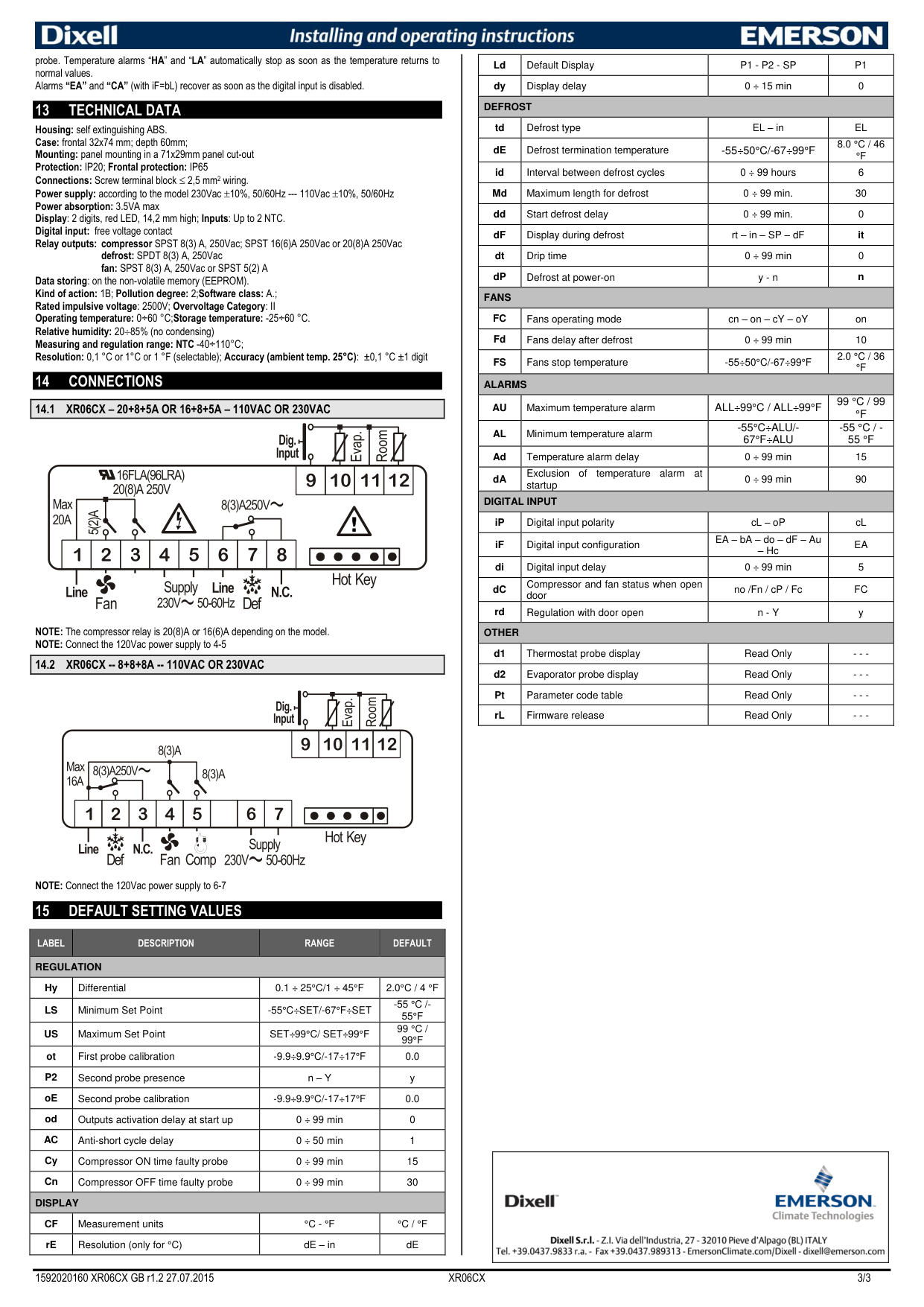
|14.1 XR06CX – 20+8+5A OR 16+8+5A – 110VAC OR 230VAC| |---|
| | | | | | | | | |---|---|---|---|---|---|---|---| | | | | | | | | |
| | | |---|---|
NOTE: The compressor relay is 20(8)A or 16(6)A depending on the model. NOTE: Connect the 120Vac power supply to 4-5
|14.2 XR06CX -- 8+8+8A -- 110VAC OR 230VAC| |---|
| | | | | | | | | |---|---|---|---|---|---|---|---| | | | | | | | | |
| | | |---|---|
NOTE: Connect the 120Vac power supply to 6-7
15 DEFAULT SETTING VALUES
|LABEL|DESCRIPTION|RANGE|DEFAULT| |---|---|---|---| |REGULATION|REGULATION|REGULATION|REGULATION| |Hy|Differential|0.1 ÷ 25°C/1 ÷ 45°F|2.0°C / 4 °F| |LS|Minimum Set Point|-55°C÷SET/-67°F÷SET|-55 °C /55°F| |US|Maximum Set Point|SET÷99°C/ SET÷99°F|99 °C / 99°F| |ot|First probe calibration|-9.9÷9.9°C/-17÷17°F|0.0| |P2|Second probe presence|n – Y|y| |oE|Second probe calibration|-9.9÷9.9°C/-17÷17°F|0.0| |od|Outputs activation delay at start up|0 ÷ 99 min|0| |AC|Anti-short cycle delay|0 ÷ 50 min|1| |Cy|Compressor ON time faulty probe|0 ÷ 99 min|15| |Cn|Compressor OFF time faulty probe|0 ÷ 99 min|30| |DISPLAY|DISPLAY|DISPLAY|DISPLAY| |CF|Measurement units|°C - °F|°C / °F| |rE|Resolution (only for °C)|dE – in|dE|
