
Ask AI
— answers from the official manualAnswers from the official manual.
Common questions
Common Questions
9 totalHow do I upgrade device software using FusionSolar app?
Under 'Maintenance', select the 'Upgrade Device' option and follow prompts to update the inverter's software version as required ensuring compatibility and performance.
How do I perform a factory reset on my device using the FusionSolar app?
Press and hold the Power button for 10 seconds until the LED flashes red. This clears all settings and returns the device to factory defaults. You will need to re-pair all connected devices after performing this action. Refer specifically to page 23 in the manual.
What are some best practices for downloading FusionSolar app updates?
Ensure your mobile phone is connected to a stable internet connection before searching 'FusionSolar' in Google Play and installing the latest version. This will ensure optimal functionality of the application.
What permissions does FusionSolar app require for proper functioning?
The app requires access to a WLAN or carrier network, permission to obtain location information, ability to use the camera, and read/write SD card content for logging exceptions.
How do I view performance statistics of my solar plant using FusionSolar app?
After logging in, go to 'Home' on the screen to see real-time PV plant overview. Detailed KPI data and status are displayed in the upper part of the screen.
How do I add or modify a PV plant on FusionSolar?
When adding or modifying PV plants, the system obtains the current location information by default when entering the PV plant location information.
Full Manual
257 pages

FusionSolar App and SUN2000 App
User Manual
Issue 07 Date 2020-05-15
########### HUAWEI TECHNOLOGIES CO., LTD.

########## Copyright © Huawei Technologies Co., Ltd. 2020. All rights reserved.
No part of this document may be reproduced or transmitted in any form or by any means without prior written consent of Huawei Technologies Co., Ltd.
########## Trademarks and Permissions

and other Huawei trademarks are trademarks of Huawei Technologies Co., Ltd.
All other trademarks and trade names mentioned in this document are the property of their respective holders.
########## Notice
The purchased products, services and features are stipulated by the contract made between Huawei and the customer. All or part of the products, services and features described in this document may not be within the purchase scope or the usage scope. Unless otherwise specified in the contract, all statements, information, and recommendations in this document are provided "AS IS" without warranties, guarantees or representations of any kind, either express or implied.
The information in this document is subject to change without notice. Every effort has been made in the preparation of this document to ensure accuracy of the contents, but all statements, information, and recommendations in this document do not constitute a warranty of any kind, express or implied.
###### Huawei Technologies Co., Ltd.
Address: Huawei Industrial Base Bantian, Longgang Shenzhen 518129 People's Republic of China
Website: https://e.huawei.com
About This Document
#### Overview
This document describes the common operations of the FusionSolar app.
#### Intended Audience
This document is intended for:
Installers
Users
#### Symbol Conventions
The symbols that may be found in this document are defined as follows.
|Symbol|Description| |---|---| ||Indicates an imminently hazardous situation which, if not avoided, will result in death or serious injury.| ||Indicates a potentially hazardous situation which, if not avoided, could result in death or serious injury.| ||Indicates a potentially hazardous situation which, if not avoided, may result in minor or moderate injury.| ||Indicates a potentially hazardous situation which, if not avoided, could result in equipment damage, data loss, performance deterioration, or unanticipated results.
NOTICE is used to address practices not related to personal injury.| ||Calls attention to important information, best practices and tips. NOTE is used to address information not related to personal injury, equipment damage, and environment deterioration.|
#### Change History
Changes between document issues are cumulative. The latest document issue contains all the changes made in earlier issues.
Issue 07 (2020-05-15) Upgraded the SUN2000 app version to SUN2000 app 3.2.00.005. Upgraded the FusionSolar app version to FusionSolar app 2.5.8.
######## Issue 06 (2020-04-11)
Updated 4.7 Settings.
Issue 05 (2020-03-15) Upgraded the SUN2000 app version to SUN2000 app 3.2.00.003. Upgraded the FusionSolar app version to FusionSolar app 2.5.7.
######## Issue 04 (2019-12-18)
Updated 1.1 Introduction to the App. Issue 03 (2019-11-29)
Upgraded the FusionSolar app version to FusionSolar app 2.5.0. Issue 02 (2019-09-10)
Upgraded the FusionSolar app version to FusionSolar app 2.3.5. Issue 01 (2019-07-25)
This issue is used for first office application (FOA).
Issue 07 (2020-05-15) Copyright © Huawei Technologies Co., Ltd. iii
Contents
About This Document.................................................................................................................... ii
Issue 07 (2020-05-15) Copyright © Huawei Technologies Co., Ltd. iv
######### 6 Operations on the Screen for Connecting to the SmartLogger ..........................................93
######### 7 Operations on the Screen for Connecting to the PID Module.........................................172
1 Overview
#### 1.1 Introduction to the App
Introduction to the FusionSolar app
The FusionSolar app is the software used to manage PV plants. On the FusionSolar app, you can create PV plants, and manage devices for solar inverters.
Introduction to the SUN2000 app
The SUN2000 app is a mobile application that communicates with commercial solar inverters or PID modules over WLAN/Bluetooth or a USB data cable, communicates with the SmartLogger over WLAN/Bluetooth, and communicates with distributed solar inverters over WLAN. The app allows you to query alarms, configure parameters, and perform routine maintenance. It is a convenient platform for maintenance. The app name is displayed as SUN2000.
#### 1.2 Downloading and Installing the App
Downloading and Installing the FusionSolar app

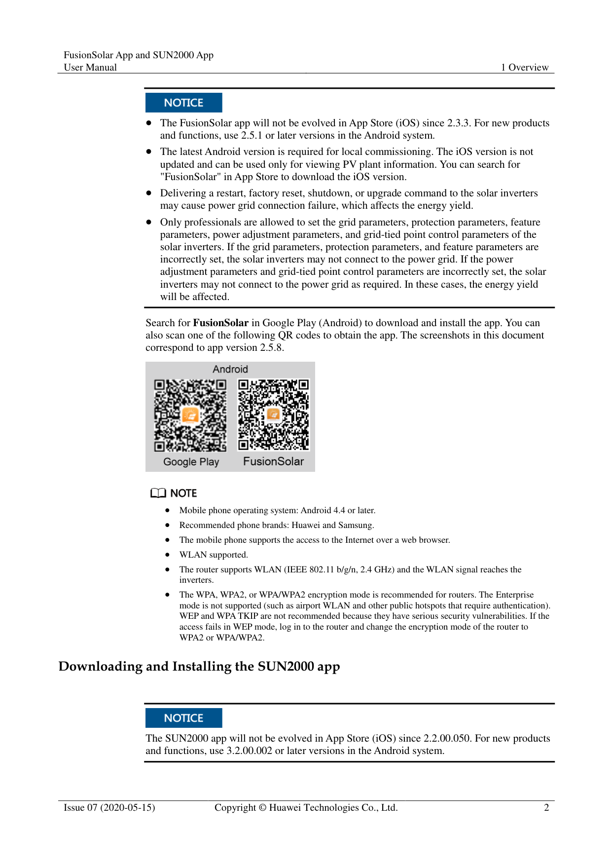
The FusionSolar app will not be evolved in App Store (iOS) since 2.3.3. For new products and functions, use 2.5.1 or later versions in the Android system.
The latest Android version is required for local commissioning. The iOS version is not updated and can be used only for viewing PV plant information. You can search for "FusionSolar" in App Store to download the iOS version.
Delivering a restart, factory reset, shutdown, or upgrade command to the solar inverters may cause power grid connection failure, which affects the energy yield.
Only professionals are allowed to set the grid parameters, protection parameters, feature parameters, power adjustment parameters, and grid-tied point control parameters of the solar inverters. If the grid parameters, protection parameters, and feature parameters are incorrectly set, the solar inverters may not connect to the power grid. If the power adjustment parameters and grid-tied point control parameters are incorrectly set, the solar inverters may not connect to the power grid as required. In these cases, the energy yield will be affected.
Search for FusionSolar in Google Play (Android) to download and install the app. You can also scan one of the following QR codes to obtain the app. The screenshots in this document correspond to app version 2.5.8.


Mobile phone operating system: Android 4.4 or later. Recommended phone brands: Huawei and Samsung. The mobile phone supports the access to the Internet over a web browser.
WLAN supported.
The router supports WLAN (IEEE 802.11 b/g/n, 2.4 GHz) and the WLAN signal reaches the inverters.
The WPA, WPA2, or WPA/WPA2 encryption mode is recommended for routers. The Enterprise mode is not supported (such as airport WLAN and other public hotspots that require authentication). WEP and WPA TKIP are not recommended because they have serious security vulnerabilities. If the access fails in WEP mode, log in to the router and change the encryption mode of the router to WPA2 or WPA/WPA2.
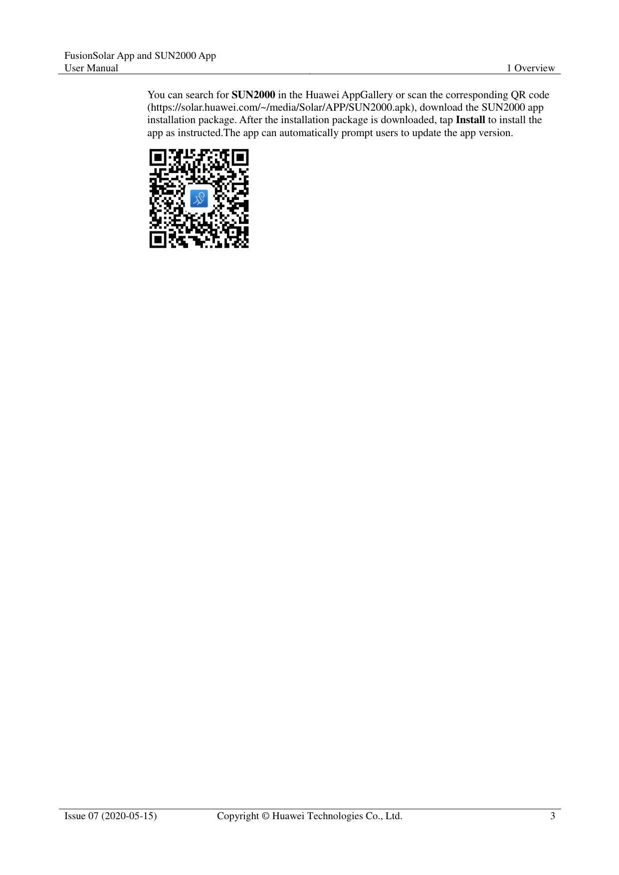
######## Downloading and Installing the SUN2000 app

The SUN2000 app will not be evolved in App Store (iOS) since 2.2.00.050. For new products and functions, use 3.2.00.002 or later versions in the Android system.
You can search for SUN2000 in the Huawei AppGallery or scan the corresponding QR code (https://solar.huawei.com/~/media/Solar/APP/SUN2000.apk), download the SUN2000 app installation package. After the installation package is downloaded, tap Install to install the app as instructed.The app can automatically prompt users to update the app version.

2 Operations on the FusionSolar APP
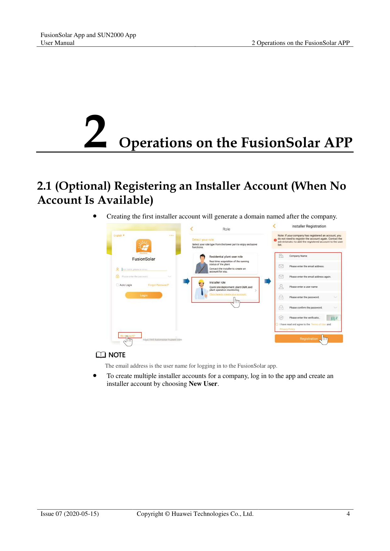
#### 2.1 (Optional) Registering an Installer Account (When NoAccount Is Available)
############ Creating the first installer account will generate a domain named after the company.


The email address is the user name for logging in to the FusionSolar app.
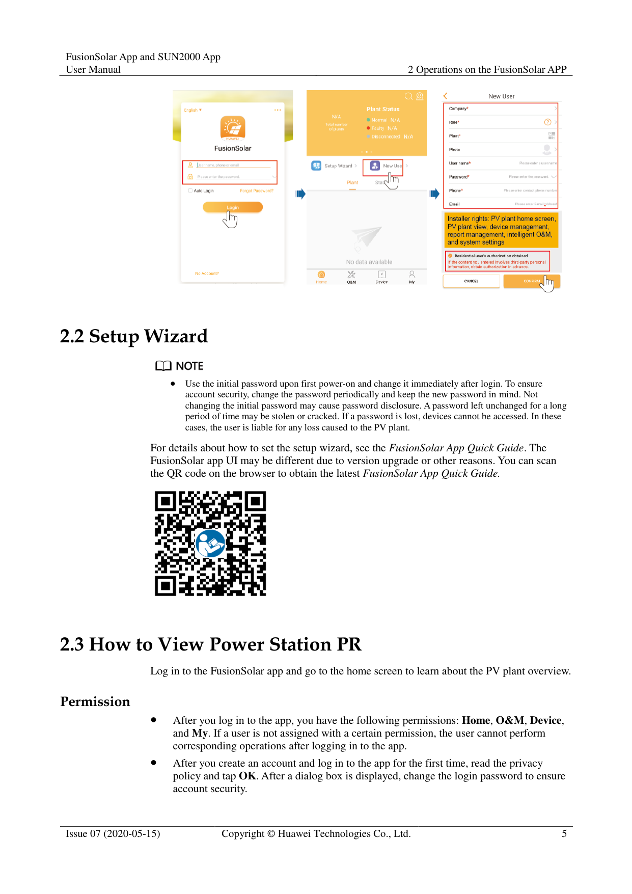
To create multiple installer accounts for a company, log in to the app and create an installer account by choosing New User.

#### 2.2 Setup Wizard

Use the initial password upon first power-on and change it immediately after login. To ensure account security, change the password periodically and keep the new password in mind. Not changing the initial password may cause password disclosure. A password left unchanged for a long period of time may be stolen or cracked. If a password is lost, devices cannot be accessed. In these cases, the user is liable for any loss caused to the PV plant.
For details about how to set the setup wizard, see the FusionSolar App Quick Guide. The FusionSolar app UI may be different due to version upgrade or other reasons. You can scan the QR code on the browser to obtain the latest FusionSolar App Quick Guide.

#### 2.3 How to View Power Station PR
Log in to the FusionSolar app and go to the home screen to learn about the PV plant overview. Permission
After you log in to the app, you have the following permissions: Home, O&M, Device, and My. If a user is not assigned with a certain permission, the user cannot perform corresponding operations after logging in to the app.
After you create an account and log in to the app for the first time, read the privacy policy and tap OK. After a dialog box is displayed, change the login password to ensure account security.
When the app is in use, the location function works, which will increase the power consumption.
Before using the app on a mobile phone, ensure that the phone has the following permissions. Otherwise, the app cannot be used properly.
After a mobile O&M engineer logs in to the app, the system reports the location information.
When a mobile inspection task is started, the location information is reported before the task is stopped.
When you add or modify a PV plant, the system obtains the current location information by default when you enter the PV plant location information.
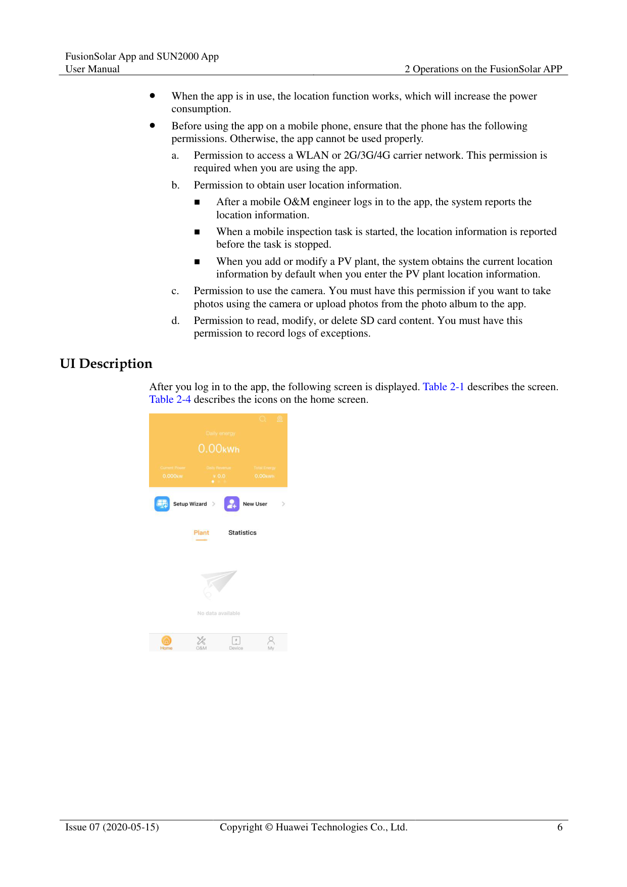
######## UI Description
After you log in to the app, the following screen is displayed. Table 2-1 describes the screen. Table 2-4 describes the icons on the home screen.

############ Table 2-1 UI description
|Function|Description| |---|---| |Home|On the Plant screen, tap a PV plant name to view its real-time information and the PV plant view.
The Statistics screen displays the energy yield, revenue statistics, PV plant ranking on the current day, and social contribution.
The PV plant KPI data, PV plant status, and real-time alarms are displayed in sequence in the upper part of the screen.| |O&M|The O&M screen displays the PV plant status, device alarms, diagnosis warning, online diagnosis, I-V curve, and mobile O&M.| |Device|The Device screen displays the device information, and is used to set device parameters and replace devices.|
|My|The My screen displays the user information, messages, local commissioning tool, PV plant management, owner management, company information, and personal settings.|
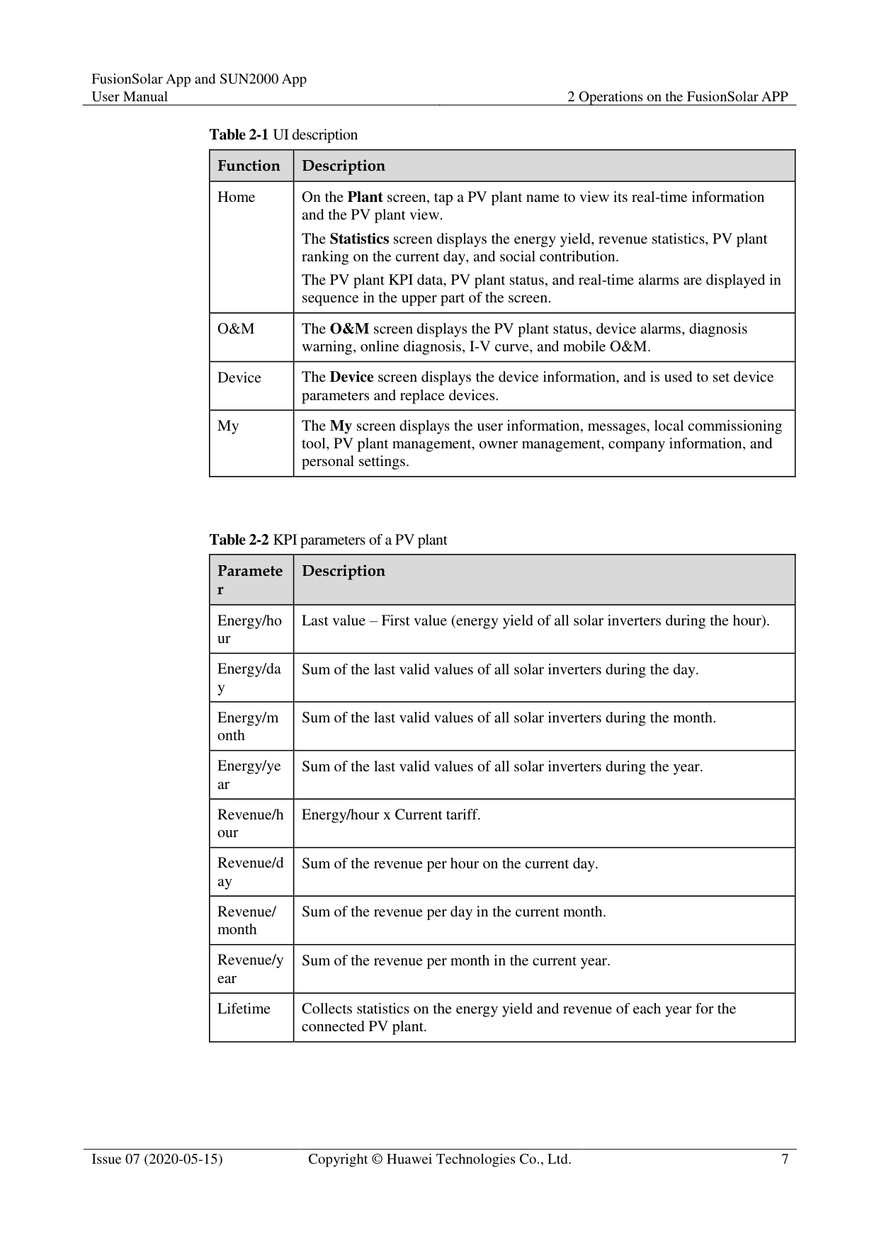
############ Table 2-2 KPI parameters of a PV plant
|Paramete r
|Description| |---|---| |Energy/ho ur|Last value – First value (energy yield of all solar inverters during the hour).| |Energy/da y|Sum of the last valid values of all solar inverters during the day.| |Energy/m onth|Sum of the last valid values of all solar inverters during the month.| |Energy/ye ar|Sum of the last valid values of all solar inverters during the year.| |Revenue/h our|Energy/hour x Current tariff.| |Revenue/d ay|Sum of the revenue per hour on the current day.| |Revenue/ month|Sum of the revenue per day in the current month.| |Revenue/y ear|Sum of the revenue per month in the current year.| |Lifetime|Collects statistics on the energy yield and revenue of each year for the connected PV plant.|
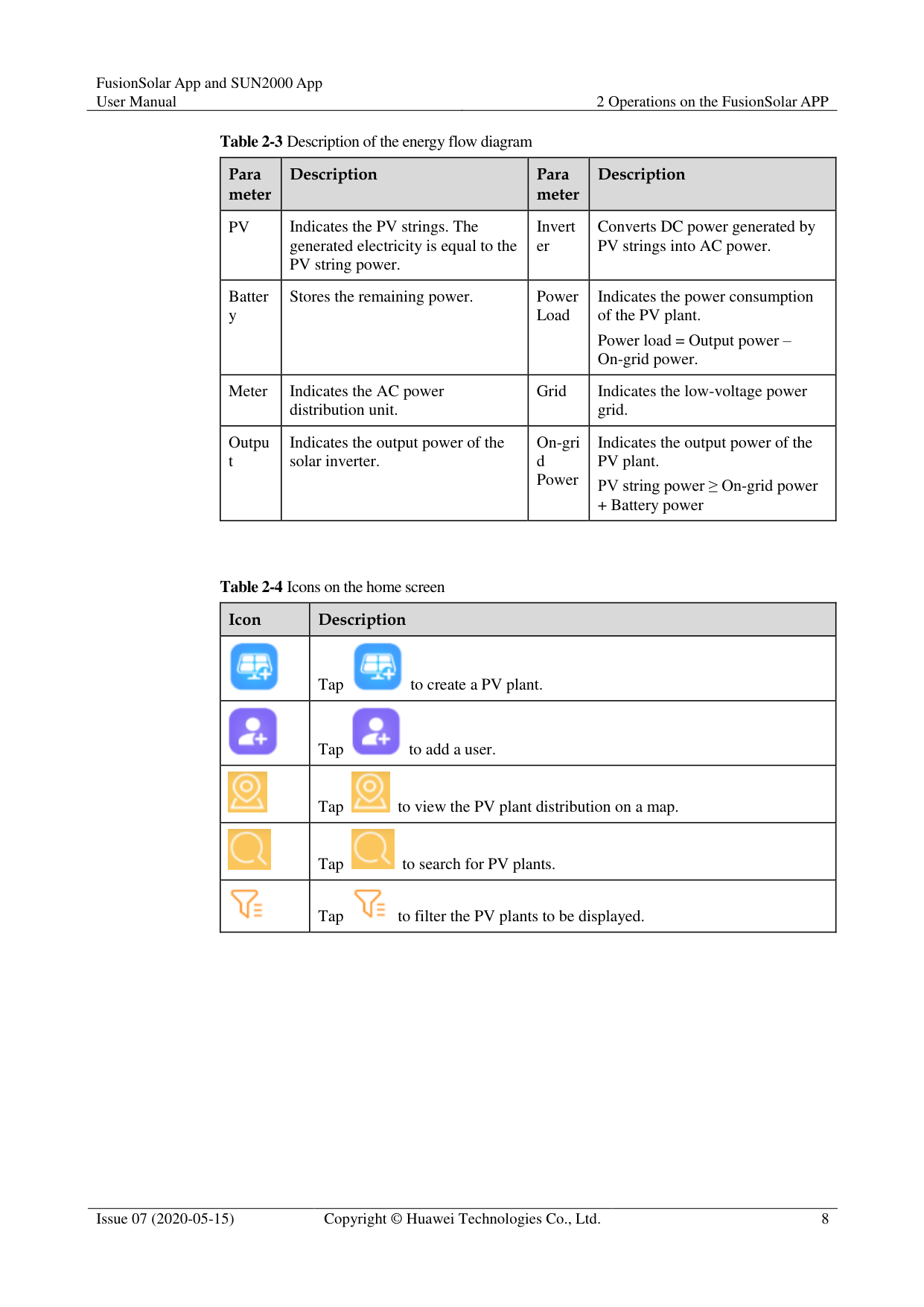
############ Table 2-3 Description of the energy flow diagram
|Para meter
|Description|Para meter
|Description| |---|---|---|---| |PV|Indicates the PV strings. The generated electricity is equal to the PV string power.|Invert er|Converts DC power generated by PV strings into AC power.| |Batter y|Stores the remaining power.|Power Load|Indicates the power consumption of the PV plant.
Power load = Output power – On-grid power.| |Meter|Indicates the AC power distribution unit.|Grid|Indicates the low-voltage power grid.|
|Outpu t|Indicates the output power of the solar inverter.|On-gri d Power|Indicates the output power of the PV plant.
PV string power ≥ On-grid power
+ Battery power|
############ Table 2-4 Icons on the home screen
|Icon|Description| |---|---| ||Tap to create a PV plant.
| ||Tap to add a user.
| ||Tap to view the PV plant distribution on a map.
| ||Tap to search for PV plants.
| ||Tap to filter the PV plants to be displayed.
|
3 Commissioning Devices
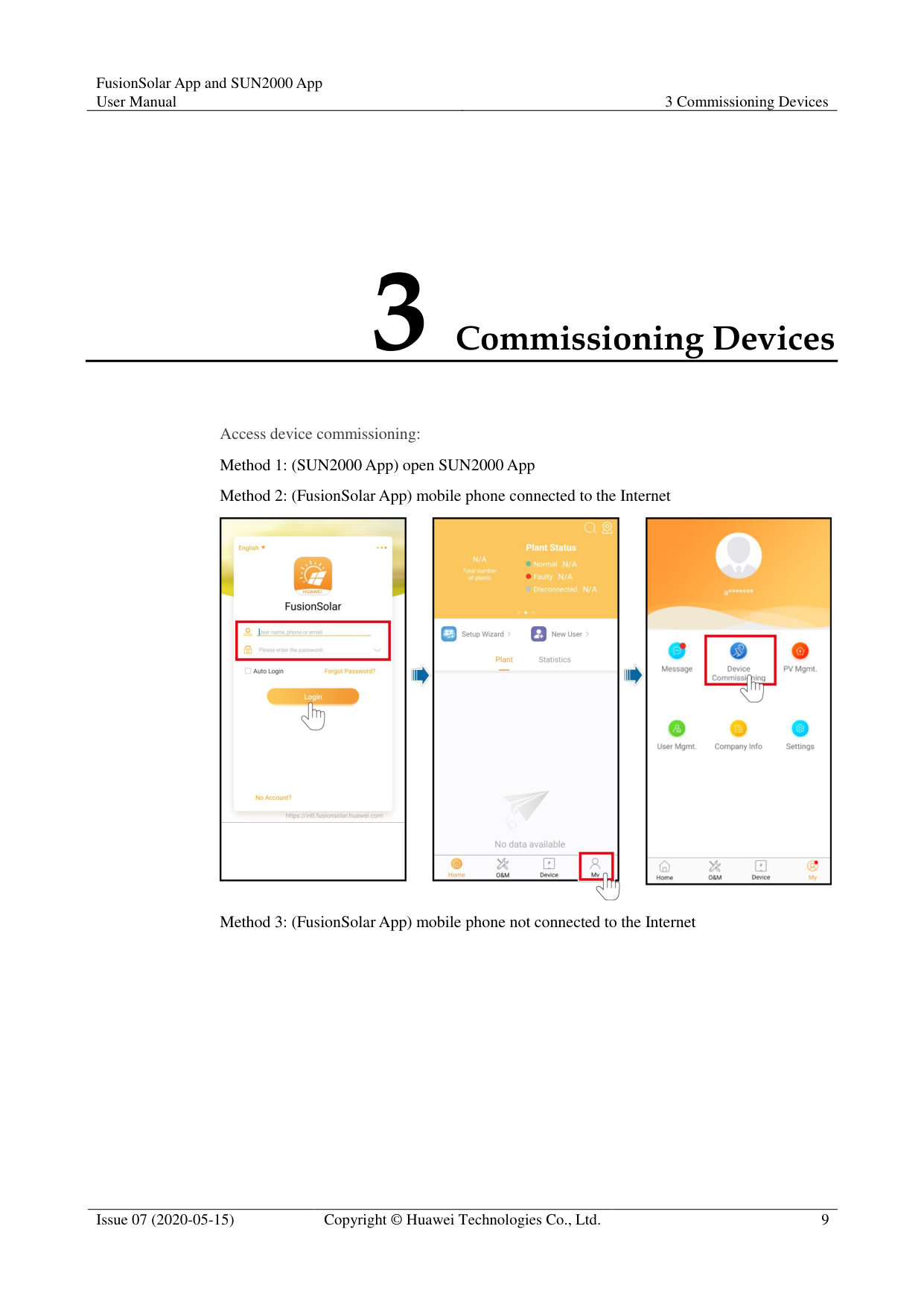
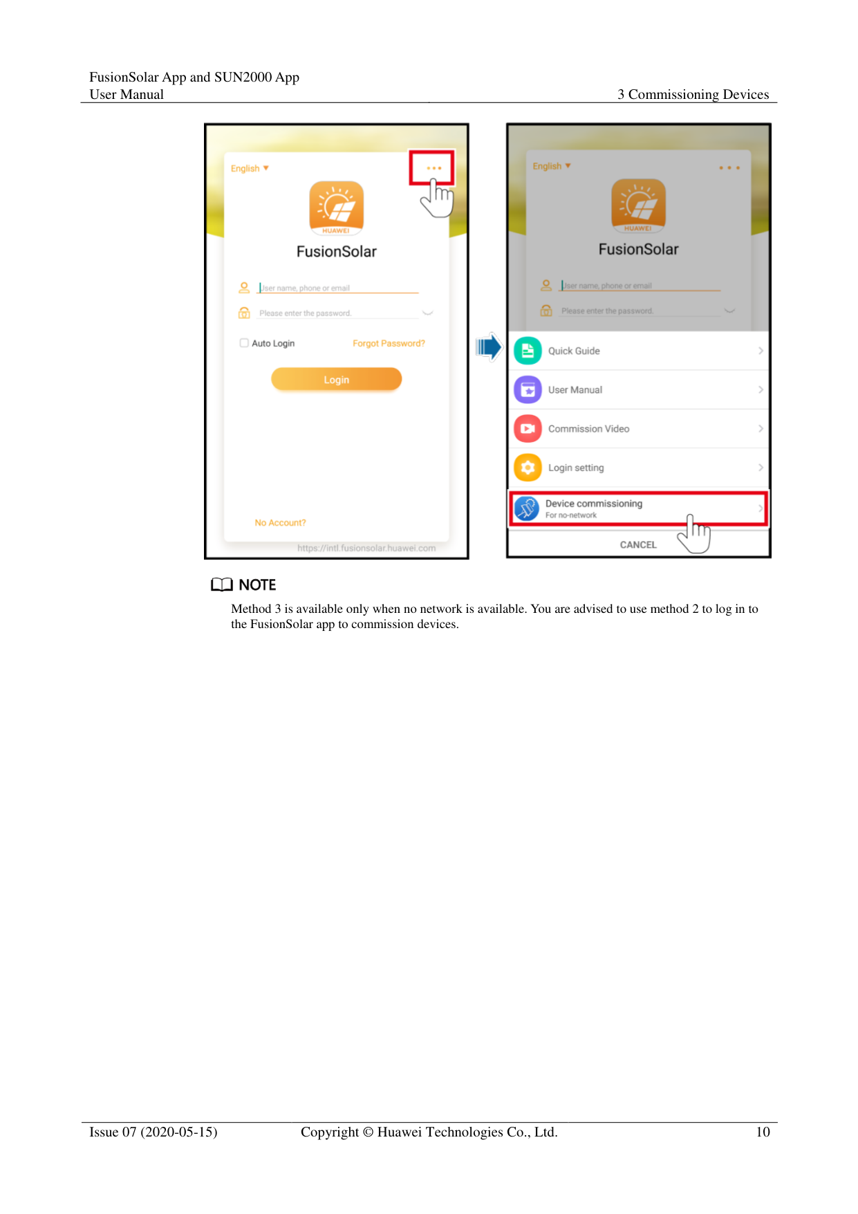
Access device commissioning:


############### Method 3 is available only when no network is available. You are advised to use method 2 to log in to the FusionSolar app to commission devices.
4 Operations on the Screen for Connecting
to the Distributed Solar Inverter

The app screenshots provided in this chapter correspond to the SUN2000 app 3.2.00.005 version. The data on the screenshots is for reference only.
Delivering a reset, factory reset, shutdown, or upgrade command to the solar inverters may cause power grid connection failure, which affects the energy yield.
Only professionals are allowed to set the grid parameters, protection parameters, feature parameters, power adjustment parameters, and grid-tied point control parameters of the solar inverters. If the grid parameters, protection parameters, and feature parameters are incorrectly set, the solar inverters may not connect to the power grid. If the power adjustment parameters and grid-tied point control parameters are incorrectly set, the solar inverters may not connect to the power grid as required. In these cases, the energy yield will be affected.
#### 4.1 Distributed Solar Inverter
######## Connection Modes
After the DC or AC side of the solar inverter is powered on, the app can connect to the solar inverter through the built-in WLAN of the solar inverter.
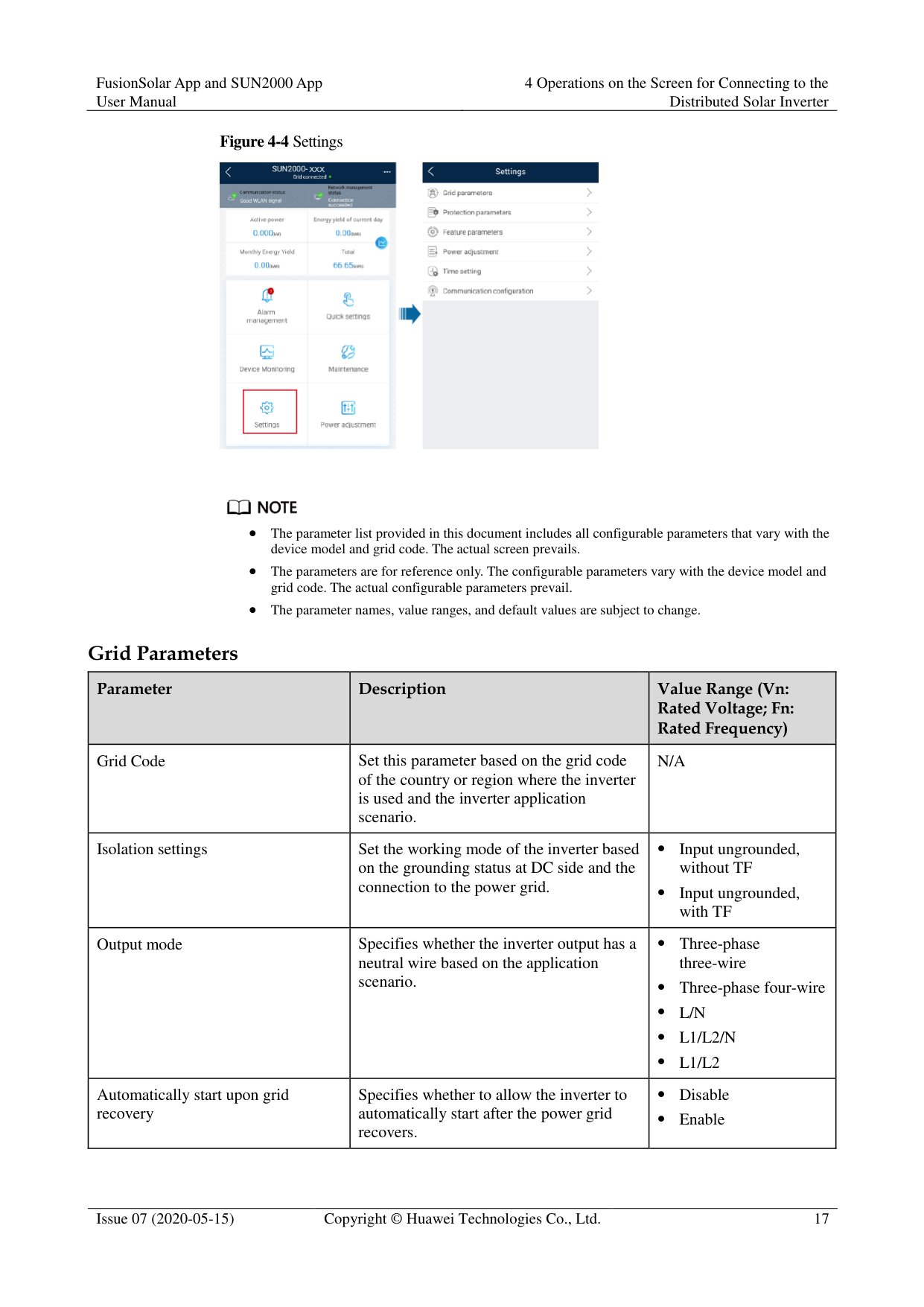
Table 4-1 Product mapping (Android)
|Solar Inverter Model
|Version|App Version| |---|---|---| |SUN2000L-(2KTL5KTL)|SUN2000L V100R001C00|3.2.00.005| |SUN2000-(2KTL-5 KTL)-L0|SUN2000L V100R001C00|3.2.00.005|
|Solar Inverter Model
|Version|App Version| |---|---|---| |SUN2000-(3.8KTL11.6KTL)-USL0|SUN2000L V100R001C10| | |SUN2000L-(4.125K TL-4.95KTL)-JP|SUN2000L V100R001C12SPC107 and later versions| | |SUN2000L-(3KTL5KTL)-CN|SUN2000L V100R001C00SPC114 and later versions| | |SUN2000-(8KTL-1 2KTL)|SUN2000MA V100R001C00| | |SUN2000-(3KTL-2 0KTL)-M0|SUN2000MA V100R001C00| |

############### The version mapping in the preceding table is subject to change and is for reference only.
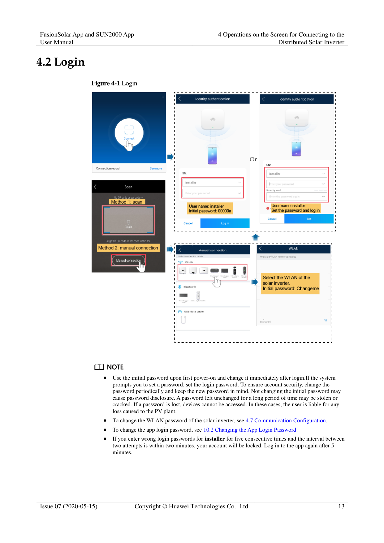
#### 4.2 Login
########### Figure 4-1 Login


Use the initial password upon first power-on and change it immediately after login.If the system prompts you to set a password, set the login password. To ensure account security, change the password periodically and keep the new password in mind. Not changing the initial password may cause password disclosure. A password left unchanged for a long period of time may be stolen or cracked. If a password is lost, devices cannot be accessed. In these cases, the user is liable for any loss caused to the PV plant.
To change the WLAN password of the solar inverter, see 4.7 Communication Configuration.
To change the app login password, see 10.2 Changing the App Login Password.
If you enter wrong login passwords for installer for five consecutive times and the interval between two attempts is within two minutes, your account will be locked. Log in to the app again after 5 minutes.
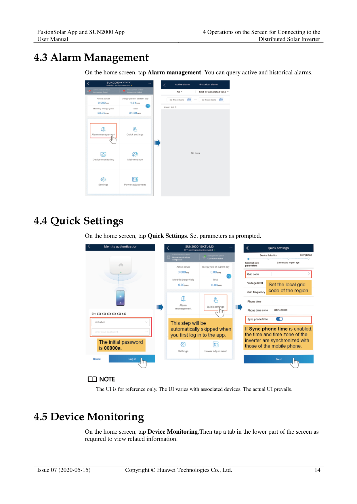
#### 4.3 Alarm Management
On the home screen, tap Alarm management. You can query active and historical alarms.

#### 4.4 Quick Settings
On the home screen, tap Quick Settings. Set parameters as prompted.


The UI is for reference only. The UI varies with associated devices. The actual UI prevails.
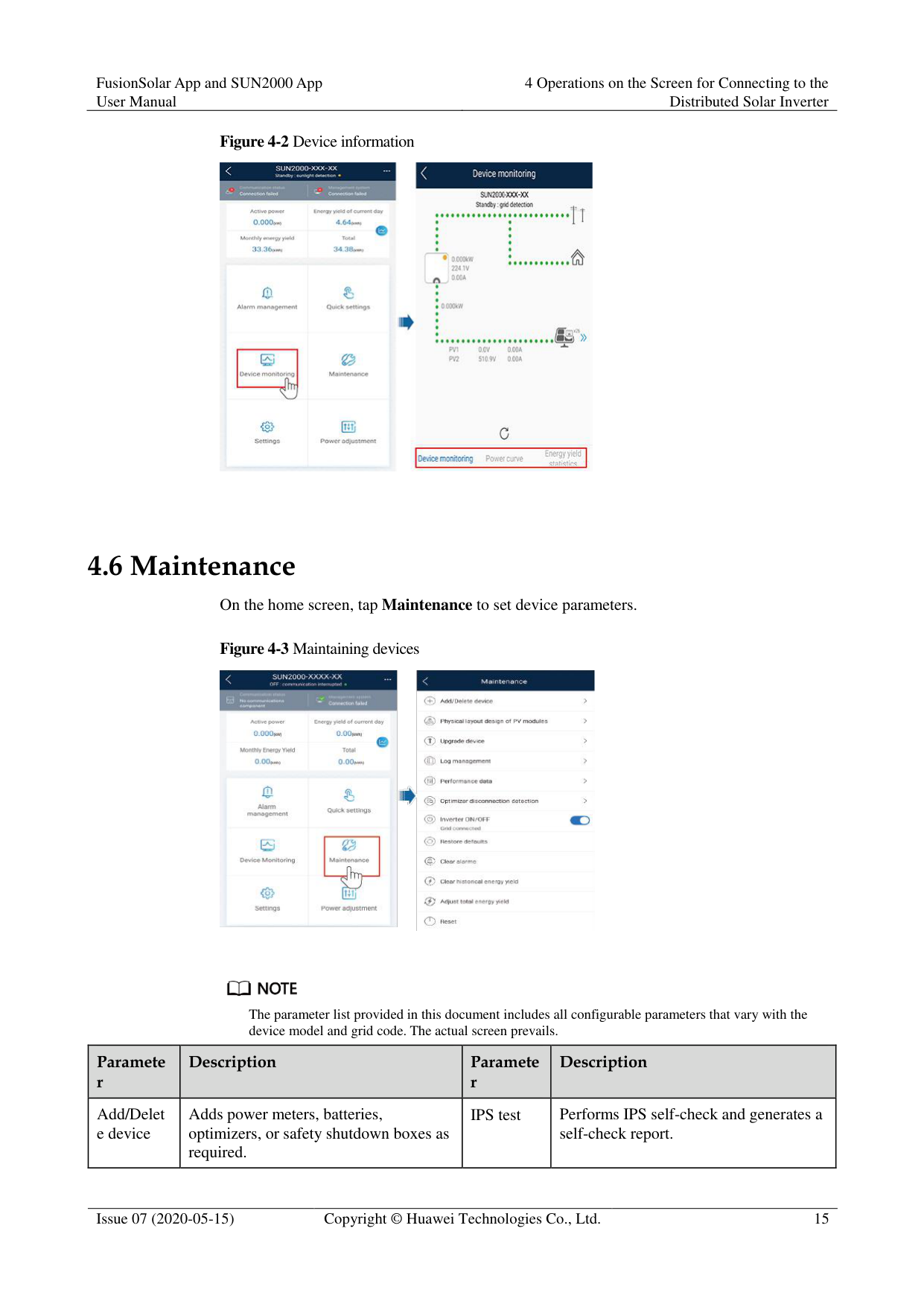
#### 4.5 Device Monitoring
On the home screen, tap Device Monitoring.Then tap a tab in the lower part of the screen as required to view related information.

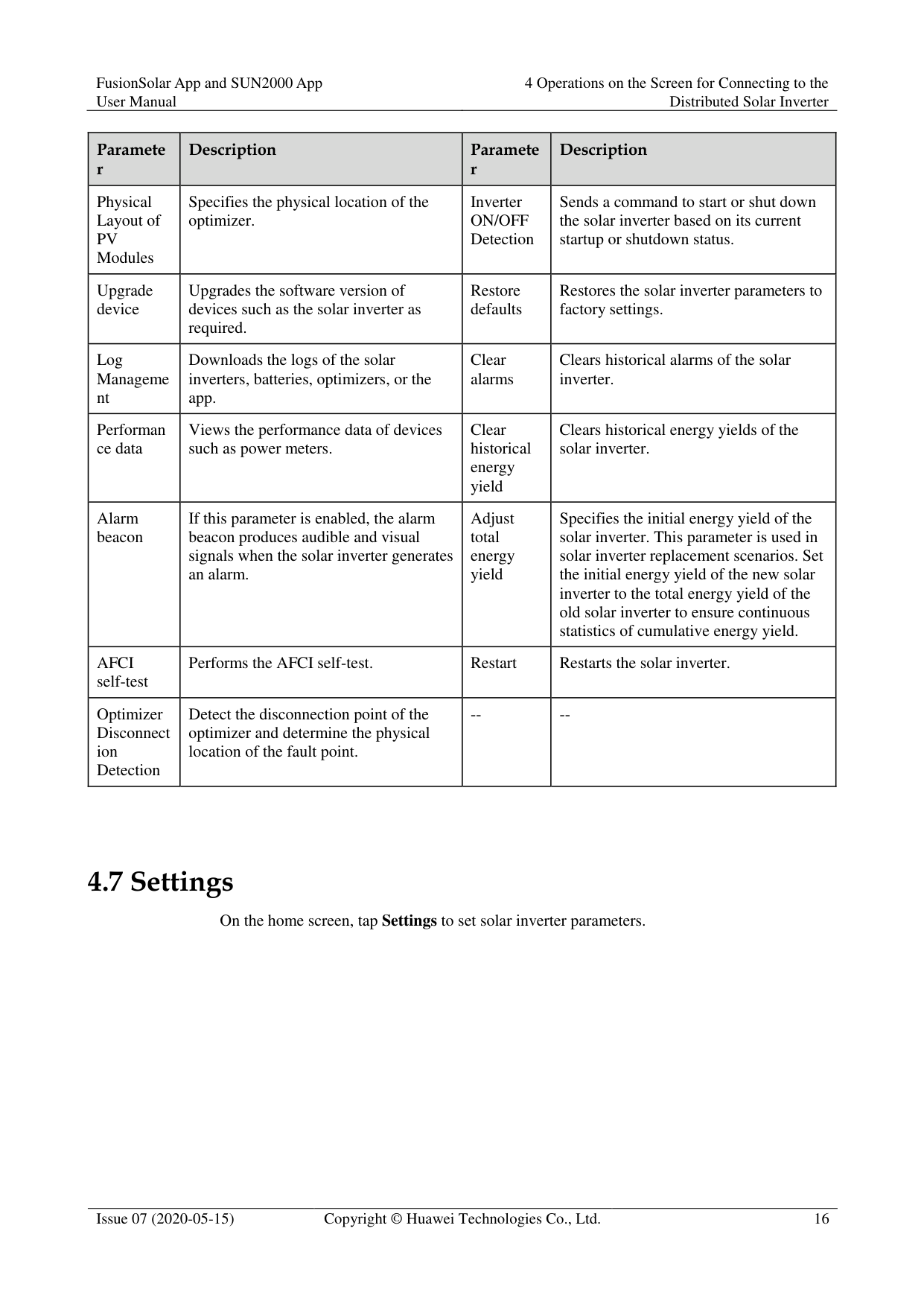
4.6 Maintenance
On the home screen, tap Maintenance to set device parameters.


The parameter list provided in this document includes all configurable parameters that vary with the device model and grid code. The actual screen prevails.
|Paramete r
|Description|Paramete r
|Description|
|---|---|---|---| |Add/Delet e device|Adds power meters, batteries, optimizers, or safety shutdown boxes as required.|IPS test|Performs IPS self-check and generates a self-check report.|
|Paramete r
|Description|Paramete r
|Description| |---|---|---|---| |Physical Layout of PV Modules|Specifies the physical location of the optimizer.|Inverter ON/OFF Detection|Sends a command to start or shut down the solar inverter based on its current startup or shutdown status.| |Upgrade device|Upgrades the software version of devices such as the solar inverter as required.|Restore defaults|Restores the solar inverter parameters to factory settings.| |Log Manageme nt|Downloads the logs of the solar inverters, batteries, optimizers, or the app.|Clear alarms|Clears historical alarms of the solar inverter.| |Performan ce data|Views the performance data of devices such as power meters.|Clear historical energy yield|Clears historical energy yields of the solar inverter.| |Alarm beacon|If this parameter is enabled, the alarm beacon produces audible and visual signals when the solar inverter generates an alarm.|Adjust total energy yield|Specifies the initial energy yield of the solar inverter. This parameter is used in solar inverter replacement scenarios. Set the initial energy yield of the new solar inverter to the total energy yield of the old solar inverter to ensure continuous statistics of cumulative energy yield.| |AFCI self-test|Performs the AFCI self-test.|Restart|Restarts the solar inverter.| |Optimizer Disconnect ion Detection|Detect the disconnection point of the optimizer and determine the physical location of the fault point.|--|--|
#### 4.7 Settings
On the home screen, tap Settings to set solar inverter parameters.
########### Figure 4-4 Settings


The parameter list provided in this document includes all configurable parameters that vary with the device model and grid code. The actual screen prevails.
The parameters are for reference only. The configurable parameters vary with the device model and grid code. The actual configurable parameters prevail.
The parameter names, value ranges, and default values are subject to change. Grid Parameters
|Parameter|Description|Value Range (Vn: Rated Voltage; Fn: Rated Frequency)
| |---|---|---| |Grid Code|Set this parameter based on the grid code of the country or region where the inverter is used and the inverter application scenario.|N/A| |Isolation settings|Set the working mode of the inverter based on the grounding status at DC side and the connection to the power grid.| Input ungrounded, without TF
Input ungrounded, with TF| |Output mode|Specifies whether the inverter output has a neutral wire based on the application scenario.| Three-phase three-wire
Three-phase four-wire
L/N
L1/L2/N
L1/L2| |Automatically start upon grid recovery|Specifies whether to allow the inverter to automatically start after the power grid recovers.| Disable
Enable|
|Parameter|Description|Value Range (Vn: Rated Voltage; Fn: Rated Frequency)
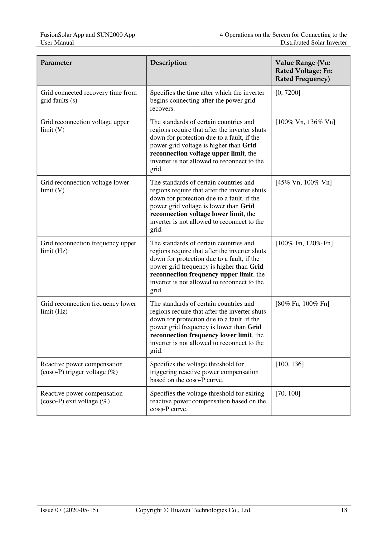
| |---|---|---| |Grid connected recovery time from grid faults (s)|Specifies the time after which the inverter begins connecting after the power grid recovers.|[0, 7200]| |Grid reconnection voltage upper limit (V)|The standards of certain countries and regions require that after the inverter shuts down for protection due to a fault, if the power grid voltage is higher than Grid reconnection voltage upper limit, the inverter is not allowed to reconnect to the grid.|[100% Vn, 136% Vn]| |Grid reconnection voltage lower limit (V)|The standards of certain countries and regions require that after the inverter shuts down for protection due to a fault, if the power grid voltage is lower than Grid reconnection voltage lower limit, the inverter is not allowed to reconnect to the grid.|[45% Vn, 100% Vn]| |Grid reconnection frequency upper limit (Hz)|The standards of certain countries and regions require that after the inverter shuts down for protection due to a fault, if the power grid frequency is higher than Grid reconnection frequency upper limit, the inverter is not allowed to reconnect to the grid.|[100% Fn, 120% Fn]| |Grid reconnection frequency lower limit (Hz)|The standards of certain countries and regions require that after the inverter shuts down for protection due to a fault, if the power grid frequency is lower than Grid
reconnection frequency lower limit, the inverter is not allowed to reconnect to the grid.|[80% Fn, 100% Fn]| |Reactive power compensation (cosφ-P) trigger voltage (%)|Specifies the voltage threshold for triggering reactive power compensation based on the cosφ-P curve.|[100, 136]| |Reactive power compensation (cosφ-P) exit voltage (%)|Specifies the voltage threshold for exiting reactive power compensation based on the cosφ-P curve.|[70, 100]|
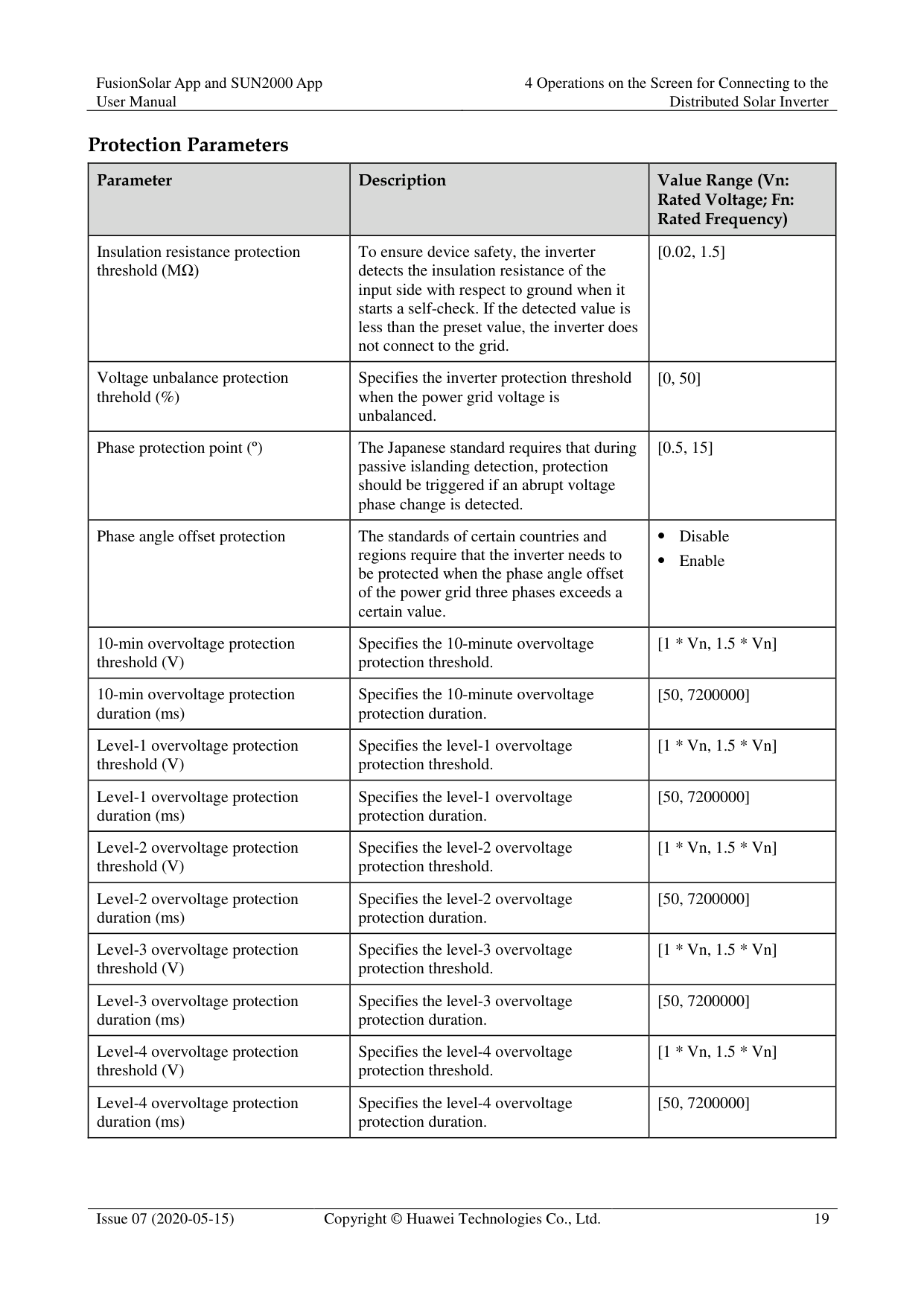
######## Protection Parameters
|Parameter|Description|Value Range (Vn: Rated Voltage; Fn: Rated Frequency)
| |---|---|---| |Insulation resistance protection threshold (MΩ)|To ensure device safety, the inverter detects the insulation resistance of the input side with respect to ground when it starts a self-check. If the detected value is less than the preset value, the inverter does not connect to the grid.|[0.02, 1.5]| |Voltage unbalance protection threhold (%)|Specifies the inverter protection threshold when the power grid voltage is unbalanced.|[0, 50]| |Phase protection point (º)|The Japanese standard requires that during passive islanding detection, protection should be triggered if an abrupt voltage phase change is detected.|[0.5, 15]| |Phase angle offset protection|The standards of certain countries and regions require that the inverter needs to be protected when the phase angle offset of the power grid three phases exceeds a certain value.| Disable
Enable| |10-min overvoltage protection threshold (V)|Specifies the 10-minute overvoltage protection threshold.|[1 * Vn, 1.5 * Vn]| |10-min overvoltage protection duration (ms)|Specifies the 10-minute overvoltage protection duration.|[50, 7200000]| |Level-1 overvoltage protection threshold (V)|Specifies the level-1 overvoltage protection threshold.|[1 * Vn, 1.5 * Vn]| |Level-1 overvoltage protection duration (ms)|Specifies the level-1 overvoltage protection duration.|[50, 7200000]| |Level-2 overvoltage protection threshold (V)|Specifies the level-2 overvoltage protection threshold.|[1 * Vn, 1.5 * Vn]| |Level-2 overvoltage protection duration (ms)|Specifies the level-2 overvoltage protection duration.|[50, 7200000]| |Level-3 overvoltage protection threshold (V)|Specifies the level-3 overvoltage protection threshold.|[1 * Vn, 1.5 * Vn]| |Level-3 overvoltage protection duration (ms)|Specifies the level-3 overvoltage protection duration.|[50, 7200000]| |Level-4 overvoltage protection threshold (V)|Specifies the level-4 overvoltage protection threshold.|[1 * Vn, 1.5 * Vn]| |Level-4 overvoltage protection duration (ms)|Specifies the level-4 overvoltage protection duration.|[50, 7200000]|
|Parameter|Description|Value Range (Vn: Rated Voltage; Fn: Rated Frequency)
| |---|---|---| |Level-5 overvoltage protection threshold (V)|Specifies the level-5 overvoltage protection threshold.|[1 * Vn, 1.5 * Vn]| |Level-5 overvoltage protection duration (ms)|Specifies the level-5 overvoltage protection duration.|[50, 7200000]| |Level-6 overvoltage protection threshold (V)|Specifies the level-6 overvoltage protection threshold.|[1 * Vn, 1.5 * Vn]|
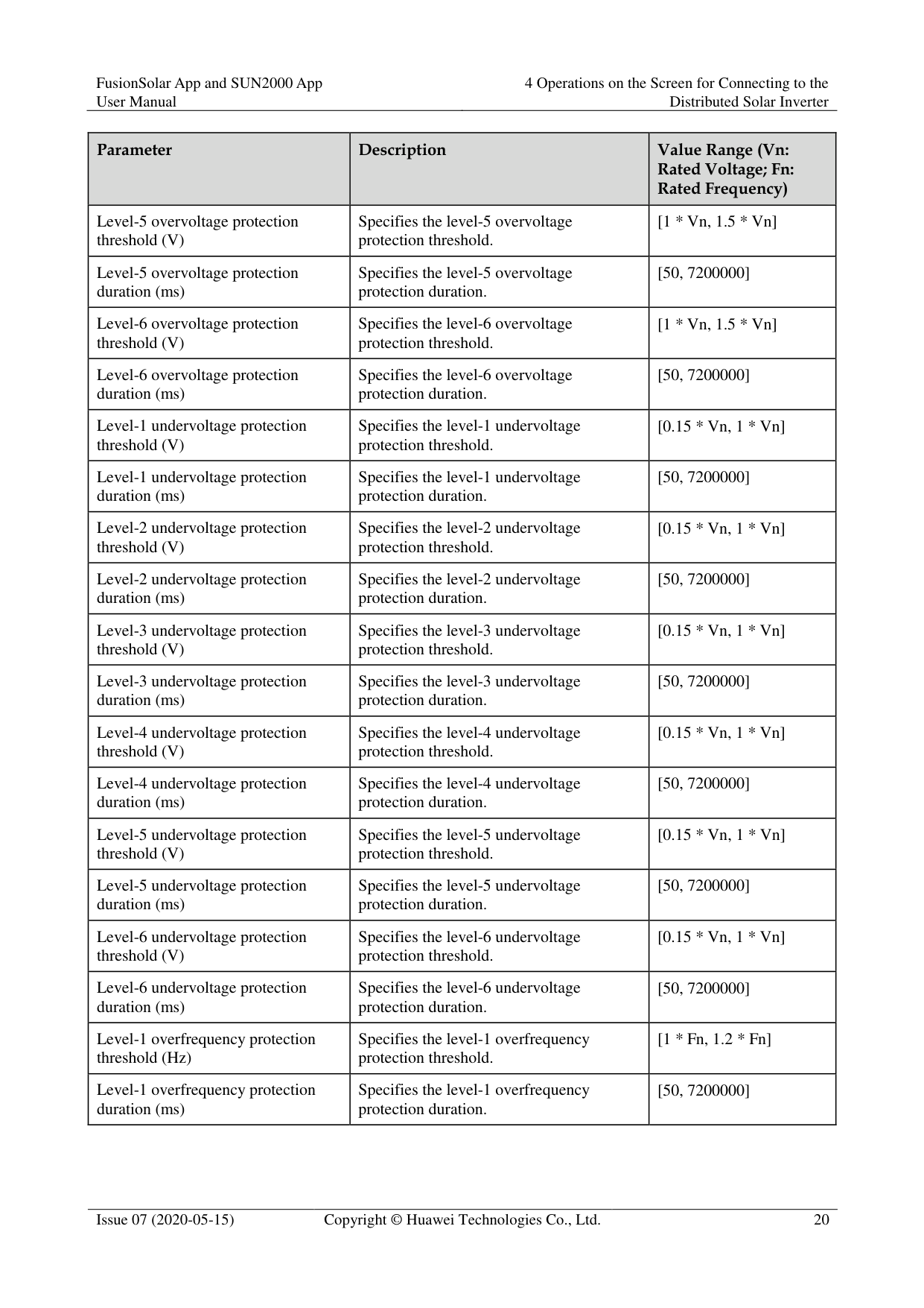
|Level-6 overvoltage protection duration (ms)|Specifies the level-6 overvoltage protection duration.|[50, 7200000]| |Level-1 undervoltage protection threshold (V)|Specifies the level-1 undervoltage protection threshold.|[0.15 * Vn, 1 * Vn]| |Level-1 undervoltage protection duration (ms)|Specifies the level-1 undervoltage protection duration.|[50, 7200000]| |Level-2 undervoltage protection threshold (V)|Specifies the level-2 undervoltage protection threshold.|[0.15 * Vn, 1 * Vn]| |Level-2 undervoltage protection duration (ms)|Specifies the level-2 undervoltage protection duration.|[50, 7200000]| |Level-3 undervoltage protection threshold (V)|Specifies the level-3 undervoltage protection threshold.|[0.15 * Vn, 1 * Vn]| |Level-3 undervoltage protection duration (ms)|Specifies the level-3 undervoltage protection duration.|[50, 7200000]| |Level-4 undervoltage protection threshold (V)|Specifies the level-4 undervoltage protection threshold.|[0.15 * Vn, 1 * Vn]| |Level-4 undervoltage protection duration (ms)|Specifies the level-4 undervoltage protection duration.|[50, 7200000]| |Level-5 undervoltage protection threshold (V)|Specifies the level-5 undervoltage protection threshold.|[0.15 * Vn, 1 * Vn]| |Level-5 undervoltage protection duration (ms)|Specifies the level-5 undervoltage protection duration.|[50, 7200000]| |Level-6 undervoltage protection threshold (V)|Specifies the level-6 undervoltage protection threshold.|[0.15 * Vn, 1 * Vn]| |Level-6 undervoltage protection duration (ms)|Specifies the level-6 undervoltage protection duration.|[50, 7200000]| |Level-1 overfrequency protection threshold (Hz)|Specifies the level-1 overfrequency protection threshold.|[1 * Fn, 1.2 * Fn]| |Level-1 overfrequency protection duration (ms)|Specifies the level-1 overfrequency protection duration.|[50, 7200000]|
|Parameter|Description|Value Range (Vn: Rated Voltage; Fn: Rated Frequency)
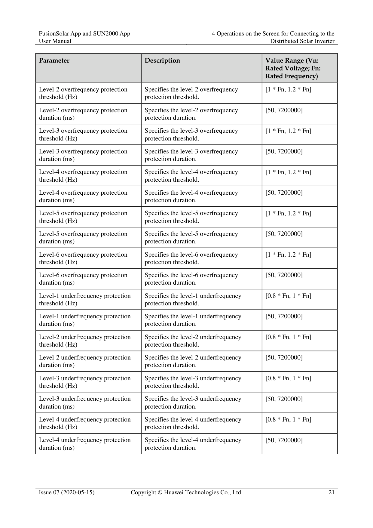
| |---|---|---| |Level-2 overfrequency protection threshold (Hz)|Specifies the level-2 overfrequency protection threshold.|[1 * Fn, 1.2 * Fn]| |Level-2 overfrequency protection duration (ms)|Specifies the level-2 overfrequency protection duration.|[50, 7200000]| |Level-3 overfrequency protection threshold (Hz)|Specifies the level-3 overfrequency protection threshold.|[1 * Fn, 1.2 * Fn]| |Level-3 overfrequency protection duration (ms)|Specifies the level-3 overfrequency protection duration.|[50, 7200000]| |Level-4 overfrequency protection threshold (Hz)|Specifies the level-4 overfrequency protection threshold.|[1 * Fn, 1.2 * Fn]| |Level-4 overfrequency protection duration (ms)|Specifies the level-4 overfrequency protection duration.|[50, 7200000]|
|Level-5 overfrequency protection threshold (Hz)|Specifies the level-5 overfrequency protection threshold.|[1 * Fn, 1.2 * Fn]| |Level-5 overfrequency protection duration (ms)|Specifies the level-5 overfrequency protection duration.|[50, 7200000]| |Level-6 overfrequency protection threshold (Hz)|Specifies the level-6 overfrequency protection threshold.|[1 * Fn, 1.2 * Fn]| |Level-6 overfrequency protection duration (ms)|Specifies the level-6 overfrequency protection duration.|[50, 7200000]| |Level-1 underfrequency protection threshold (Hz)|Specifies the level-1 underfrequency protection threshold.|[0.8 * Fn, 1 * Fn]| |Level-1 underfrequency protection duration (ms)|Specifies the level-1 underfrequency protection duration.|[50, 7200000]| |Level-2 underfrequency protection threshold (Hz)|Specifies the level-2 underfrequency protection threshold.|[0.8 * Fn, 1 * Fn]| |Level-2 underfrequency protection duration (ms)|Specifies the level-2 underfrequency protection duration.|[50, 7200000]| |Level-3 underfrequency protection threshold (Hz)|Specifies the level-3 underfrequency protection threshold.|[0.8 * Fn, 1 * Fn]| |Level-3 underfrequency protection duration (ms)|Specifies the level-3 underfrequency protection duration.|[50, 7200000]| |Level-4 underfrequency protection threshold (Hz)|Specifies the level-4 underfrequency protection threshold.|[0.8 * Fn, 1 * Fn]| |Level-4 underfrequency protection duration (ms)|Specifies the level-4 underfrequency protection duration.|[50, 7200000]|
|Parameter|Description|Value Range (Vn: Rated Voltage; Fn: Rated Frequency)
| |---|---|---| |Level-5 underfrequency protection threshold (Hz)|Specifies the level-5 underfrequency protection threshold.|[0.8 * Fn, 1 * Fn]| |Level-5 underfrequency protection duration (ms)|Specifies the level-5 underfrequency protection duration.|[50, 7200000]| |Level-6 underfrequency protection threshold (Hz)|Specifies the level-6 underfrequency protection threshold.|[0.8 * Fn, 1 * Fn]| |Level-6 underfrequency protection duration (ms)|Specifies the level-6 underfrequency protection duration.|[50, 7200000]|
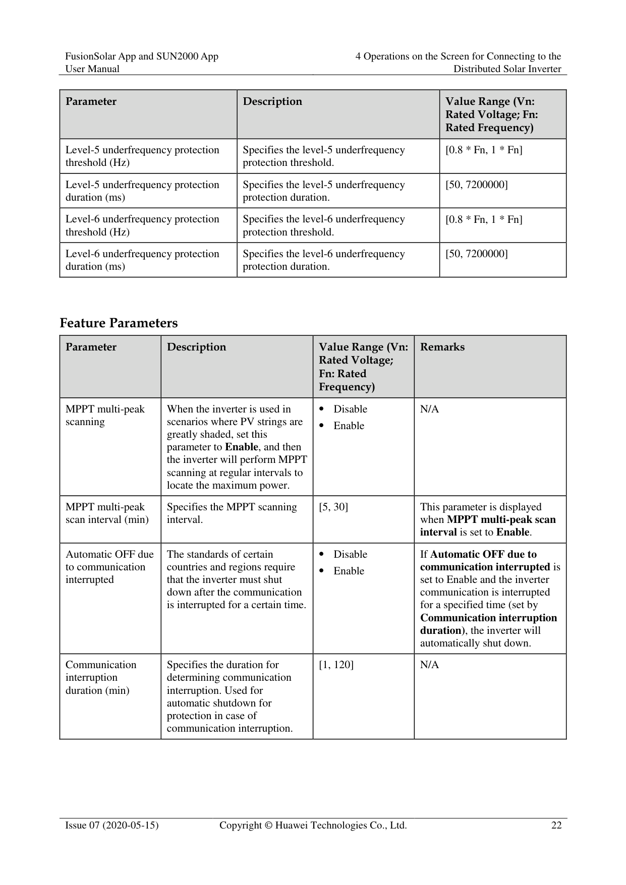
######## Feature Parameters
|Parameter|Description|Value Range (Vn: Rated Voltage; Fn: Rated Frequency)
|Remarks|
|---|---|---|---| |MPPT multi-peak scanning|When the inverter is used in scenarios where PV strings are greatly shaded, set this parameter to Enable, and then the inverter will perform MPPT scanning at regular intervals to locate the maximum power.| Disable
Enable|N/A| |MPPT multi-peak scan interval (min)|Specifies the MPPT scanning interval.|[5, 30]|This parameter is displayed when MPPT multi-peak scan interval is set to Enable.| |Automatic OFF due to communication interrupted|The standards of certain countries and regions require that the inverter must shut down after the communication is interrupted for a certain time.| Disable
Enable|If Automatic OFF due to communication interrupted is
set to Enable and the inverter communication is interrupted for a specified time (set by
Communication interruption duration), the inverter will automatically shut down.| |Communication interruption duration (min)|Specifies the duration for determining communication interruption. Used for automatic shutdown for protection in case of communication interruption.|[1, 120]|N/A|
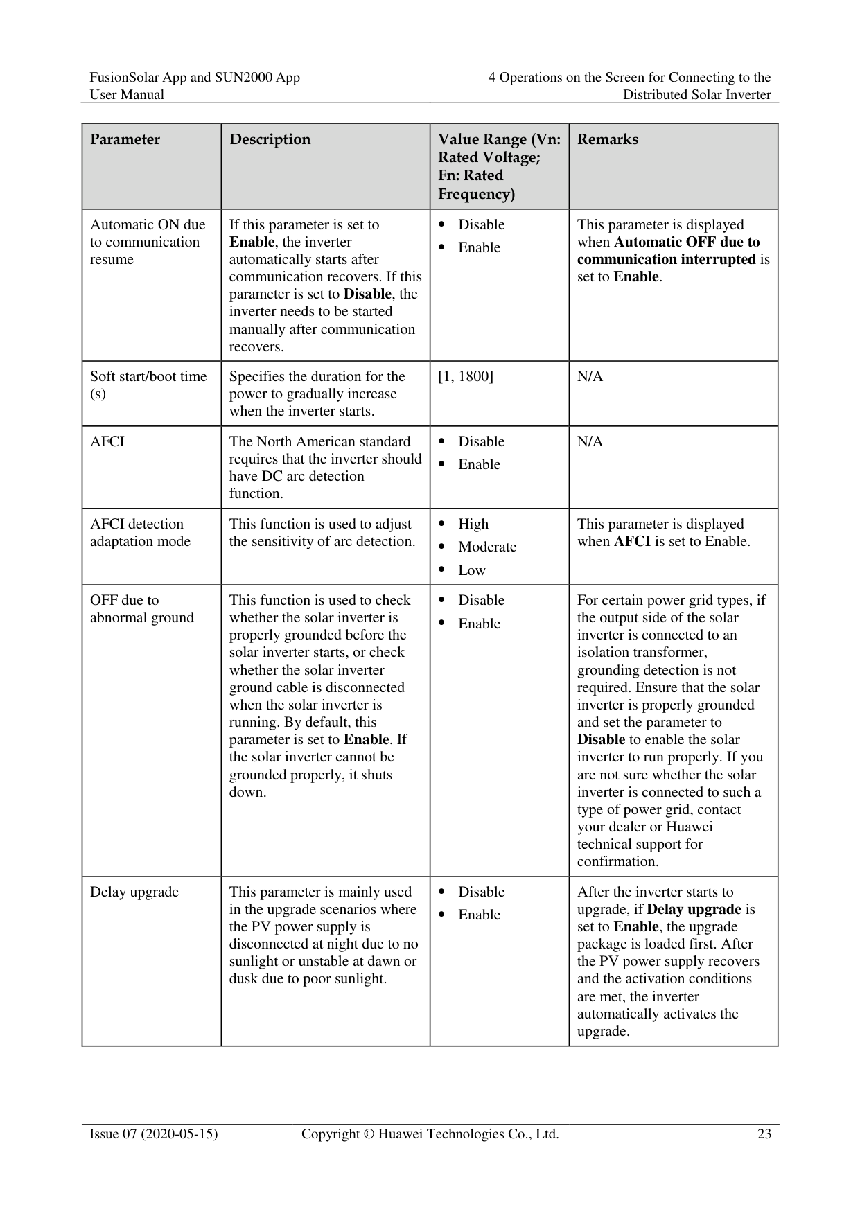
|Parameter|Description|Value Range (Vn: Rated Voltage; Fn: Rated Frequency)
|Remarks| |---|---|---|---| |Automatic ON due to communication resume|If this parameter is set to Enable, the inverter automatically starts after communication recovers. If this parameter is set to Disable, the inverter needs to be started manually after communication recovers.| Disable
Enable|This parameter is displayed when Automatic OFF due to communication interrupted is set to Enable.| |Soft start/boot time (s)|Specifies the duration for the power to gradually increase when the inverter starts.|[1, 1800]|N/A| |AFCI|The North American standard requires that the inverter should have DC arc detection function.| Disable
Enable|N/A| |AFCI detection adaptation mode|This function is used to adjust the sensitivity of arc detection.| High
Moderate
Low|This parameter is displayed when AFCI is set to Enable.| |OFF due to abnormal ground|This function is used to check whether the solar inverter is properly grounded before the solar inverter starts, or check whether the solar inverter ground cable is disconnected when the solar inverter is running. By default, this parameter is set to Enable. If the solar inverter cannot be grounded properly, it shuts down.| Disable
Enable|For certain power grid types, if the output side of the solar inverter is connected to an isolation transformer, grounding detection is not required. Ensure that the solar inverter is properly grounded and set the parameter to Disable to enable the solar inverter to run properly. If you are not sure whether the solar inverter is connected to such a type of power grid, contact your dealer or Huawei technical support for confirmation.| |Delay upgrade|This parameter is mainly used in the upgrade scenarios where the PV power supply is disconnected at night due to no sunlight or unstable at dawn or dusk due to poor sunlight.| Disable
Enable|After the inverter starts to upgrade, if Delay upgrade is set to Enable, the upgrade package is loaded first. After the PV power supply recovers and the activation conditions are met, the inverter automatically activates the upgrade.|
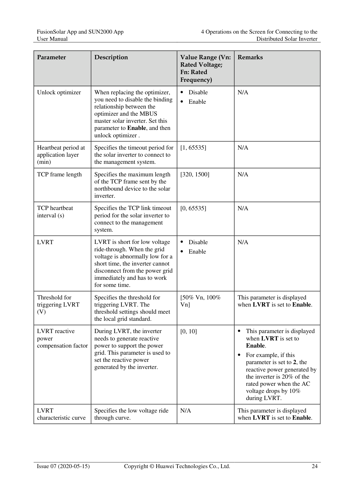
|Parameter|Description|Value Range (Vn: Rated Voltage; Fn: Rated Frequency)
|Remarks| |---|---|---|---| |Unlock optimizer|When replacing the optimizer, you need to disable the binding relationship between the optimizer and the MBUS master solar inverter. Set this parameter to Enable, and then unlock optimizer .| Disable
Enable|N/A| |Heartbeat period at application layer (min)|Specifies the timeout period for the solar inverter to connect to the management system.|[1, 65535]|N/A| |TCP frame length|Specifies the maximum length of the TCP frame sent by the northbound device to the solar inverter.|[320, 1500]|N/A| |TCP heartbeat interval (s)|Specifies the TCP link timeout period for the solar inverter to connect to the management system.|[0, 65535]|N/A| |LVRT|LVRT is short for low voltage ride-through. When the grid voltage is abnormally low for a short time, the inverter cannot disconnect from the power grid immediately and has to work for some time.| Disable
Enable|N/A| |Threshold for triggering LVRT (V)|Specifies the threshold for triggering LVRT. The threshold settings should meet the local grid standard.|[50% Vn, 100% Vn]|This parameter is displayed when LVRT is set to Enable.|
|LVRT reactive power compensation factor|During LVRT, the inverter needs to generate reactive power to support the power grid. This parameter is used to set the reactive power generated by the inverter.|[0, 10]| This parameter is displayed when LVRT is set to Enable.
For example, if this parameter is set to 2, the reactive power generated by the inverter is 20% of the rated power when the AC voltage drops by 10% during LVRT.| |LVRT characteristic curve|Specifies the low voltage ride through curve.|N/A|This parameter is displayed when LVRT is set to Enable.|
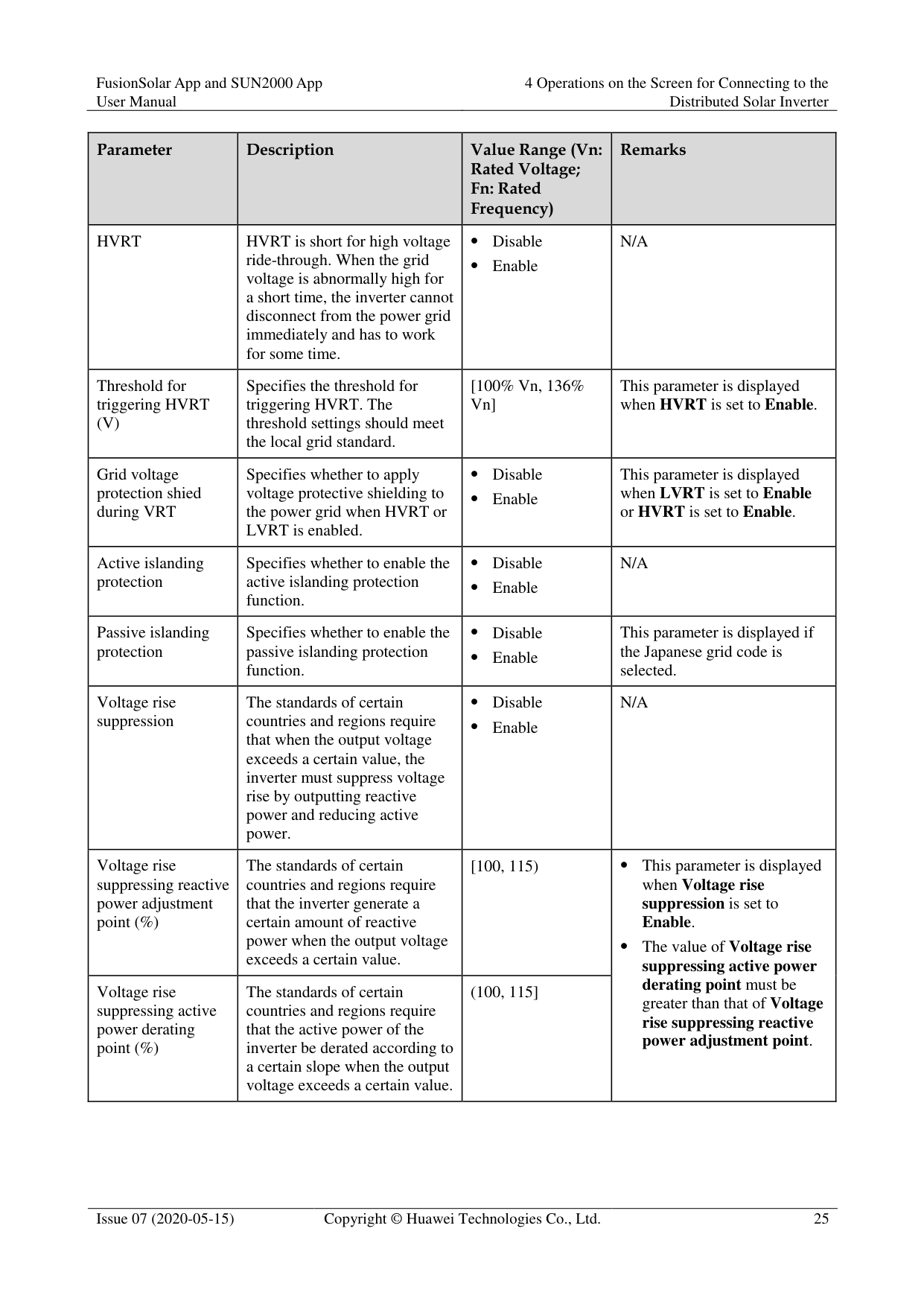
|Parameter|Description|Value Range (Vn: Rated Voltage; Fn: Rated Frequency)
|Remarks| |---|---|---|---| |HVRT|HVRT is short for high voltage ride-through. When the grid voltage is abnormally high for a short time, the inverter cannot disconnect from the power grid immediately and has to work for some time.| Disable
Enable|N/A| |Threshold for triggering HVRT (V)|Specifies the threshold for triggering HVRT. The threshold settings should meet the local grid standard.|[100% Vn, 136% Vn]|This parameter is displayed when HVRT is set to Enable.| |Grid voltage protection shied during VRT|Specifies whether to apply voltage protective shielding to the power grid when HVRT or LVRT is enabled.| Disable
Enable|This parameter is displayed when LVRT is set to Enable or HVRT is set to Enable.| |Active islanding protection|Specifies whether to enable the active islanding protection function.| Disable
Enable|N/A| |Passive islanding protection|Specifies whether to enable the passive islanding protection function.| Disable
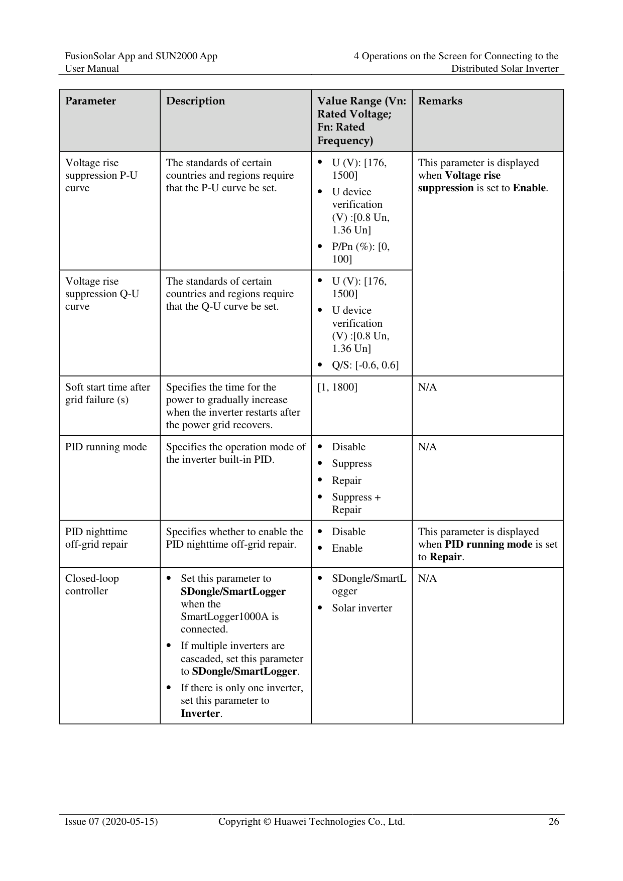
Enable|This parameter is displayed if the Japanese grid code is selected.| |Voltage rise suppression|The standards of certain countries and regions require that when the output voltage exceeds a certain value, the inverter must suppress voltage rise by outputting reactive power and reducing active power.| Disable
Enable|N/A| |Voltage rise suppressing reactive power adjustment point (%)|The standards of certain countries and regions require that the inverter generate a certain amount of reactive power when the output voltage exceeds a certain value.|[100, 115)| This parameter is displayed when Voltage rise suppression is set to Enable.
The value of Voltage rise suppressing active power derating point must be greater than that of Voltage
rise suppressing reactive power adjustment point.
| |Voltage rise suppressing active power derating point (%)|The standards of certain countries and regions require that the active power of the inverter be derated according to a certain slope when the output voltage exceeds a certain value.|(100, 115]| This parameter is displayed when Voltage rise suppression is set to Enable.
The value of Voltage rise suppressing active power derating point must be greater than that of Voltage
rise suppressing reactive power adjustment point.
|
|Parameter|Description|Value Range (Vn: Rated Voltage; Fn: Rated Frequency)
|Remarks| |---|---|---|---| |Voltage rise suppression P-U curve|The standards of certain countries and regions require that the P-U curve be set.| U (V): [176, 1500]
U device verification (V) :[0.8 Un, 1.36 Un]
P/Pn (%): [0, 100]|This parameter is displayed when Voltage rise suppression is set to Enable.| |Voltage rise suppression Q-U curve|The standards of certain countries and regions require that the Q-U curve be set.| U (V): [176, 1500]
U device verification (V) :[0.8 Un, 1.36 Un]
Q/S: [-0.6, 0.6]|This parameter is displayed when Voltage rise suppression is set to Enable.| |Soft start time after grid failure (s)|Specifies the time for the power to gradually increase when the inverter restarts after the power grid recovers.|[1, 1800]|N/A| |PID running mode|Specifies the operation mode of the inverter built-in PID.| Disable
Suppress
Repair
Suppress + Repair|N/A| |PID nighttime off-grid repair|Specifies whether to enable the PID nighttime off-grid repair.| Disable
Enable|This parameter is displayed when PID running mode is set to Repair.| |Closed-loop controller| Set this parameter to SDongle/SmartLogger when the SmartLogger1000A is connected.
If multiple inverters are cascaded, set this parameter to SDongle/SmartLogger.
If there is only one inverter, set this parameter to Inverter.| SDongle/SmartL ogger
Solar inverter|N/A|
|Parameter|Description|Value Range (Vn: Rated Voltage; Fn: Rated Frequency)
|Remarks| |---|---|---|---| |Active power output limit for fail-safe (%)|When the communication between the SDongle/SmartLogger, power meter, and solar inverter is interrupted, the solar inverter output is limited.|[0, 100]|N/A|
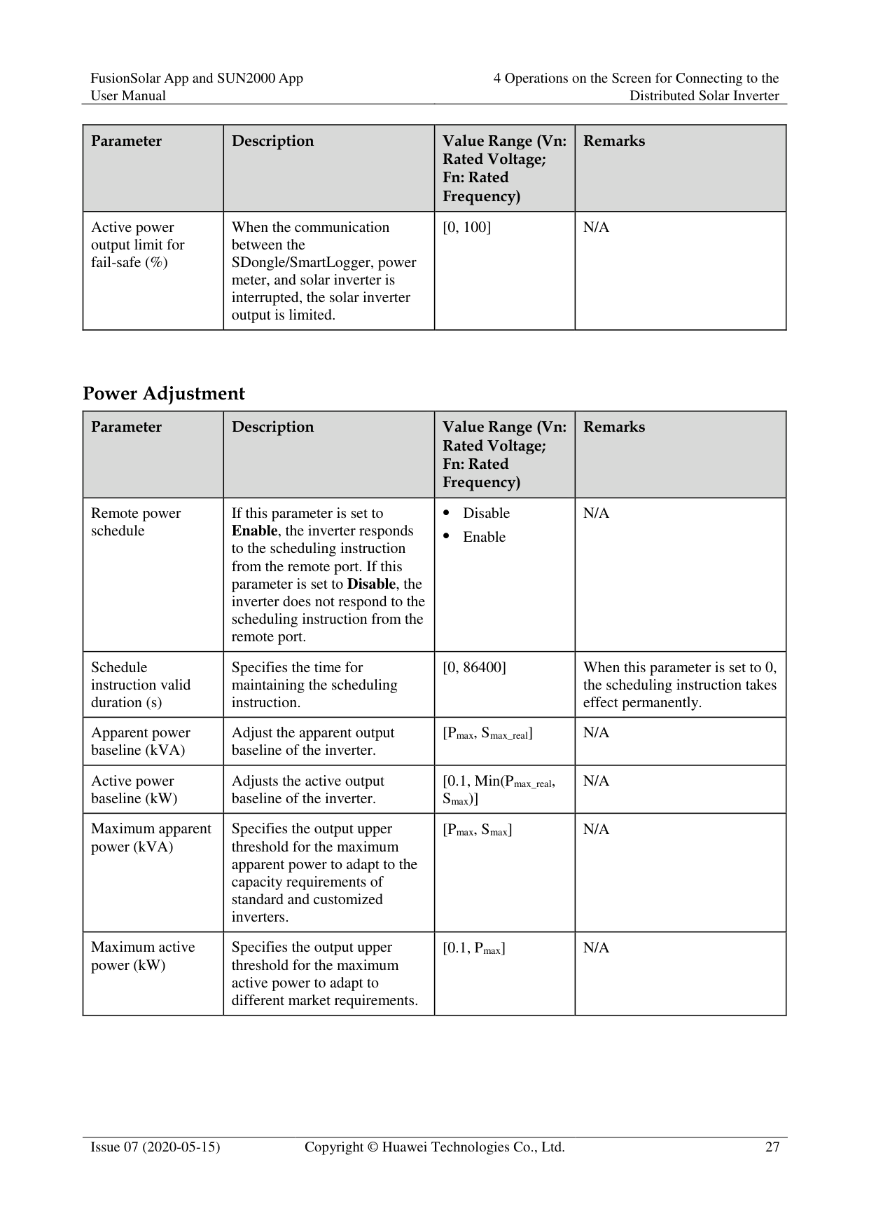
######## Power Adjustment
|Parameter|Description|Value Range (Vn: Rated Voltage; Fn: Rated Frequency)
|Remarks| |---|---|---|---| |Remote power schedule|If this parameter is set to Enable, the inverter responds to the scheduling instruction from the remote port. If this parameter is set to Disable, the inverter does not respond to the scheduling instruction from the remote port.| Disable
Enable|N/A| |Schedule instruction valid duration (s)|Specifies the time for maintaining the scheduling instruction.|[0, 86400]|When this parameter is set to 0, the scheduling instruction takes effect permanently.| |Apparent power baseline (kVA)|Adjust the apparent output baseline of the inverter.|[Pmax, Smax_real]|N/A| |Active power baseline (kW)|Adjusts the active output baseline of the inverter.|[0.1, Min(Pmax_real, Smax)]|N/A| |Maximum apparent power (kVA)|Specifies the output upper threshold for the maximum apparent power to adapt to the capacity requirements of standard and customized inverters.|[Pmax, Smax]|N/A| |Maximum active power (kW)|Specifies the output upper threshold for the maximum active power to adapt to different market requirements.|[0.1, Pmax]|N/A|
|Parameter|Description|Value Range (Vn: Rated Voltage; Fn: Rated Frequency)
|Remarks| |---|---|---|---| |OFF at %0 power limit|If this parameter is set to Enable, the inverter shuts down after receiving the 0% power limit command. If this parameter is set to Disable, the inverter does not shut down after receiving the 0% power limit command.| Disable
Enable|N/A| |Active power change gradient (%/s)|Specifies the change speed of the inverter active power.|[0.1, 1000]|N/A| |Derated by fixed active power (kW)|Adjusts the active power output of the inverter by fixed value.|[0, Pmax]|N/A| |Active power percentage derating (%)|Adjusts the active power output of the inverter by percentage.|[0, 100]|If this parameter is set to 100, the solar inverter generates power based on the maximum output power.| |Reactive power change gradient (%/s)|Specifies the change speed of the inverter reactive power.|[0.1, 1000]|N/A|

|Reactive power compensation (Q/S)|Specifies the reactive power output by the inverter.|[-1, 1]|N/A| |Power factor|Specifies the power factor of the inverter.|[–1.000, –0.800] U [0.800, 1.000]|N/A| |Overfrequency derating|If this parameter is set to Enable, the active power of the inverter will be derated according to a certain slope when the grid frequency exceeds the frequency that triggers overfrequency derating.| Disable
Enable|N/A| |Frequency for triggering overfrequency derating (Hz)|The standards of certain countries and regions require that the output active power of inverters be derated when the power grid frequency exceeds a certain value.| 50Hz: [40, 60] 60Hz: [48, 72]| This parameter is displayed when Overfrequency derating is set to Enable.
When setting this parameter, ensure that the following condition is met: Frequency for exiting overfrequency derating ≤ Trigger frequency of overfrequency derating <
| |Frequency for exiting overfrequency derating (Hz)|Specifies the frequency threshold for exiting overfrequency derating.| 50Hz: [40, 60] 60Hz: [48, 72]| This parameter is displayed when Overfrequency derating is set to Enable.
When setting this parameter, ensure that the following condition is met: Frequency for exiting overfrequency derating ≤ Trigger frequency of overfrequency derating <
|
|Parameter|Description|Value Range (Vn: Rated Voltage; Fn: Rated Frequency)
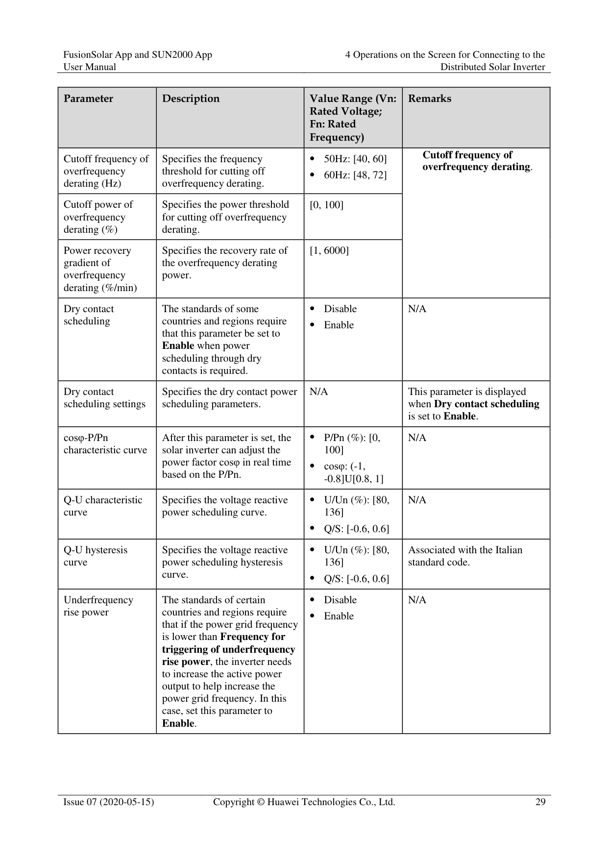
|Remarks| |---|---|---|---| |Cutoff frequency of overfrequency derating (Hz)|Specifies the frequency threshold for cutting off overfrequency derating.| 50Hz: [40, 60] 60Hz: [48, 72]|Cutoff frequency of overfrequency derating.
| |Cutoff power of overfrequency derating (%)|Specifies the power threshold for cutting off overfrequency derating.|[0, 100]|Cutoff frequency of overfrequency derating.
| |Power recovery gradient of overfrequency derating (%/min)|Specifies the recovery rate of the overfrequency derating power.|[1, 6000]|Cutoff frequency of overfrequency derating.
| |Dry contact scheduling|The standards of some countries and regions require that this parameter be set to Enable when power scheduling through dry contacts is required.| Disable
Enable|N/A| |Dry contact scheduling settings|Specifies the dry contact power scheduling parameters.|N/A|This parameter is displayed when Dry contact scheduling is set to Enable.| |cosφ-P/Pn characteristic curve|After this parameter is set, the solar inverter can adjust the power factor cosφ in real time based on the P/Pn.| P/Pn (%): [0, 100]
cosφ: (-1,
-0.8]U[0.8, 1]|N/A| |Q-U characteristic curve|Specifies the voltage reactive power scheduling curve.| U/Un (%): [80, 136]
Q/S: [-0.6, 0.6]|N/A| |Q-U hysteresis curve|Specifies the voltage reactive power scheduling hysteresis curve.| U/Un (%): [80, 136]
Q/S: [-0.6, 0.6]|Associated with the Italian standard code.| |Underfrequency rise power|The standards of certain countries and regions require that if the power grid frequency is lower than Frequency for
triggering of underfrequency rise power, the inverter needs to increase the active power output to help increase the power grid frequency. In this case, set this parameter to Enable.| Disable
Enable|N/A|
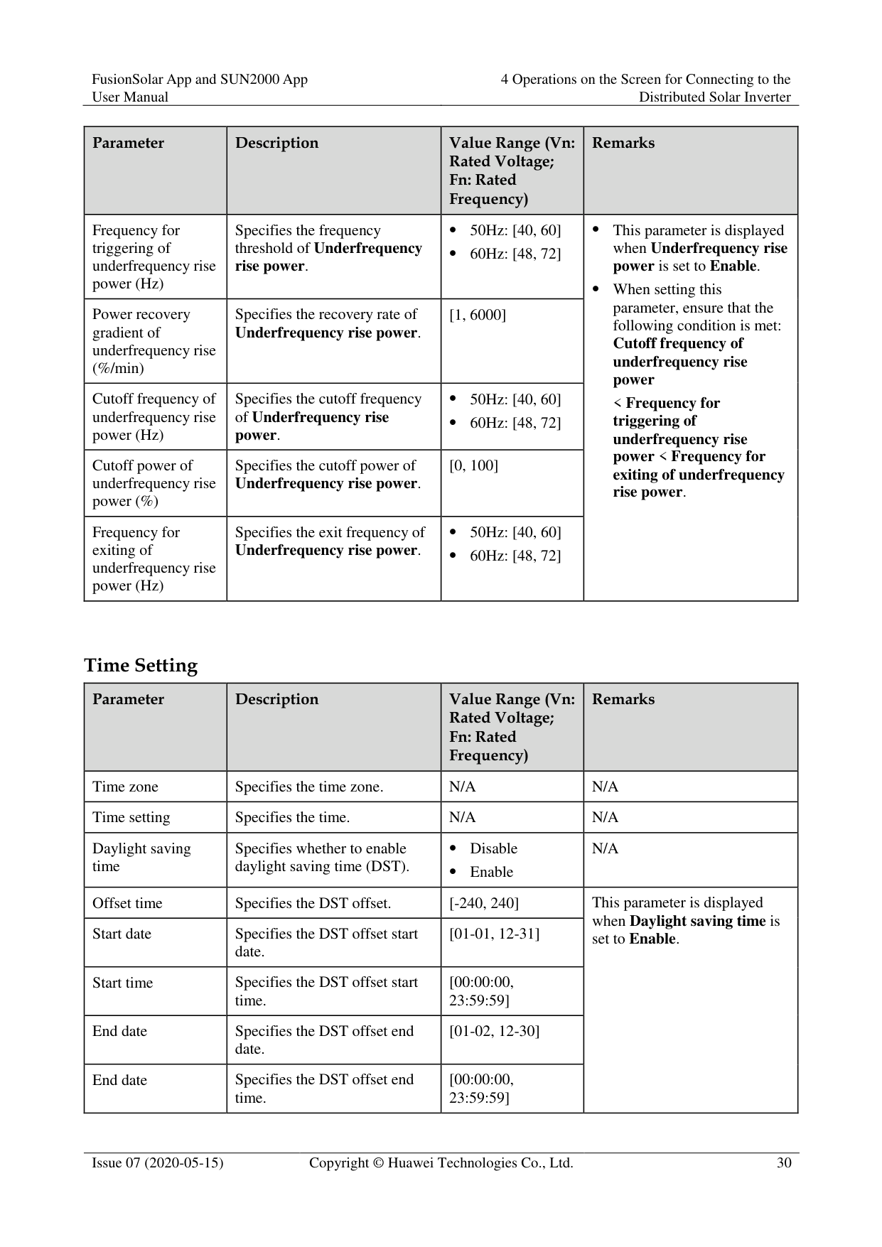
|Parameter|Description|Value Range (Vn: Rated Voltage; Fn: Rated Frequency)
|Remarks| |---|---|---|---| |Frequency for triggering of underfrequency rise power (Hz)|Specifies the frequency threshold of Underfrequency rise power.| 50Hz: [40, 60] 60Hz: [48, 72]| This parameter is displayed when Underfrequency rise power is set to Enable.
When setting this parameter, ensure that the following condition is met: Cutoff frequency of underfrequency rise power < Frequency for triggering of underfrequency rise power < Frequency for exiting of underfrequency rise power.
| |Power recovery gradient of underfrequency rise (%/min)|Specifies the recovery rate of Underfrequency rise power.|[1, 6000]| This parameter is displayed when Underfrequency rise power is set to Enable.
When setting this parameter, ensure that the following condition is met: Cutoff frequency of underfrequency rise power < Frequency for triggering of underfrequency rise power < Frequency for exiting of underfrequency rise power.
| |Cutoff frequency of underfrequency rise power (Hz)|Specifies the cutoff frequency of Underfrequency rise power.| 50Hz: [40, 60] 60Hz: [48, 72]| This parameter is displayed when Underfrequency rise power is set to Enable.
When setting this parameter, ensure that the following condition is met: Cutoff frequency of underfrequency rise power < Frequency for triggering of underfrequency rise power < Frequency for exiting of underfrequency rise power.
|
|Cutoff power of underfrequency rise power (%)|Specifies the cutoff power of Underfrequency rise power.|[0, 100]| This parameter is displayed when Underfrequency rise power is set to Enable.
When setting this parameter, ensure that the following condition is met: Cutoff frequency of underfrequency rise power < Frequency for triggering of underfrequency rise power < Frequency for exiting of underfrequency rise power.
| |Frequency for exiting of underfrequency rise power (Hz)|Specifies the exit frequency of Underfrequency rise power.| 50Hz: [40, 60] 60Hz: [48, 72]| This parameter is displayed when Underfrequency rise power is set to Enable.
When setting this parameter, ensure that the following condition is met: Cutoff frequency of underfrequency rise power < Frequency for triggering of underfrequency rise power < Frequency for exiting of underfrequency rise power.
|
######## Time Setting
|Parameter|Description|Value Range (Vn: Rated Voltage; Fn: Rated Frequency)
|Remarks| |---|---|---|---| |Time zone|Specifies the time zone.|N/A|N/A| |Time setting|Specifies the time.|N/A|N/A| |Daylight saving time|Specifies whether to enable daylight saving time (DST).| Disable
Enable|N/A| |Offset time|Specifies the DST offset.|[-240, 240]|This parameter is displayed when Daylight saving time is set to Enable.
| |Start date|Specifies the DST offset start date.|[01-01, 12-31]|This parameter is displayed when Daylight saving time is set to Enable.
| |Start time|Specifies the DST offset start time.|[00:00:00, 23:59:59]|This parameter is displayed when Daylight saving time is set to Enable.
| |End date|Specifies the DST offset end date.|[01-02, 12-30]|This parameter is displayed when Daylight saving time is set to Enable.
| |End date|Specifies the DST offset end time.|[00:00:00, 23:59:59]|This parameter is displayed when Daylight saving time is set to Enable.
|
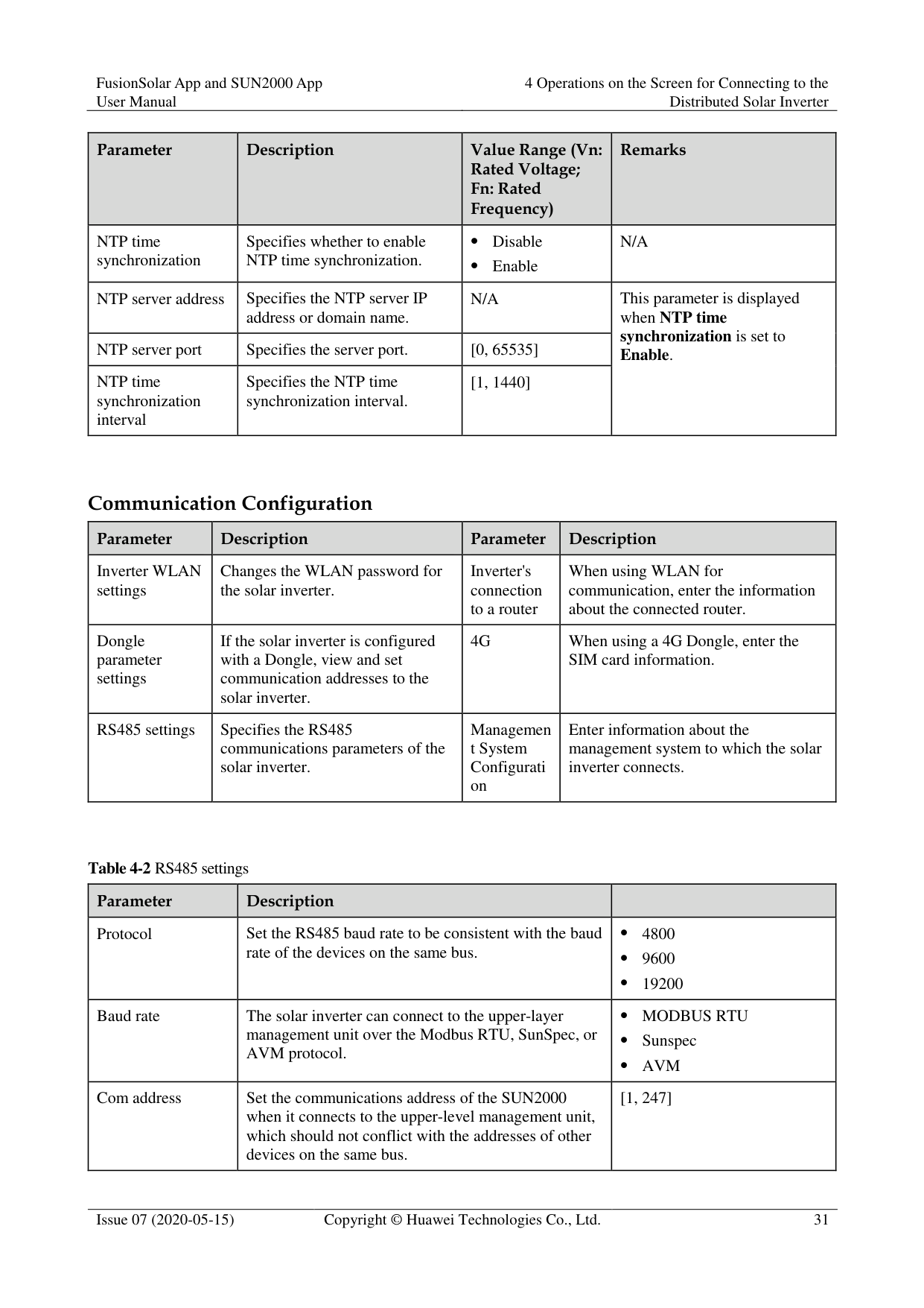
|Parameter|Description|Value Range (Vn: Rated Voltage; Fn: Rated Frequency)
|Remarks| |---|---|---|---| |NTP time synchronization|Specifies whether to enable NTP time synchronization.| Disable
Enable|N/A| |NTP server address|Specifies the NTP server IP address or domain name.|N/A|This parameter is displayed when NTP time synchronization is set to Enable.| |NTP server port|Specifies the server port.|[0, 65535]|This parameter is displayed when NTP time synchronization is set to Enable.| |NTP time synchronization interval|Specifies the NTP time synchronization interval.|[1, 1440]|This parameter is displayed when NTP time synchronization is set to Enable.|
######## Communication Configuration
|Parameter|Description|Parameter|Description| |---|---|---|---| |Inverter WLAN settings|Changes the WLAN password for the solar inverter.|Inverter's connection to a router|When using WLAN for communication, enter the information about the connected router.| |Dongle parameter settings|If the solar inverter is configured with a Dongle, view and set communication addresses to the solar inverter.|4G|When using a 4G Dongle, enter the SIM card information.| |RS485 settings|Specifies the RS485 communications parameters of the solar inverter.|Managemen t System Configurati on|Enter information about the management system to which the solar inverter connects.|
|Parameter|Description| | |---|---|---| |Protocol|Set the RS485 baud rate to be consistent with the baud rate of the devices on the same bus.| 4800 9600 19200| |Baud rate|The solar inverter can connect to the upper-layer management unit over the Modbus RTU, SunSpec, or AVM protocol.| MODBUS RTU
Sunspec
AVM| |Com address|Set the communications address of the SUN2000 when it connects to the upper-level management unit, which should not conflict with the addresses of other devices on the same bus.|[1, 247]|
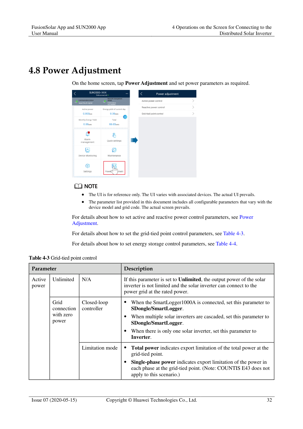
#### 4.8 Power Adjustment
On the home screen, tap Power Adjustment and set power parameters as required.


The UI is for reference only. The UI varies with associated devices. The actual UI prevails.
The parameter list provided in this document includes all configurable parameters that vary with the device model and grid code. The actual screen prevails.
For details about how to set active and reactive power control parameters, see Power Adjustment.
For details about how to set the grid-tied point control parameters, see Table 4-3. For details about how to set energy storage control parameters, see Table 4-4.
|Parameter|Parameter|Parameter|Description| |---|---|---|---| |Active power|Unlimited|N/A|If this parameter is set to Unlimited, the output power of the solar inverter is not limited and the solar inverter can connect to the power grid at the rated power.| |Active power|Grid connection with zero power|Closed-loop controller| When the SmartLogger1000A is connected, set this parameter to
SDongle/SmartLogger.
When multiple solar inverters are cascaded, set this parameter to
SDongle/SmartLogger.
When there is only one solar inverter, set this parameter to
Inverter.| |Active power|Grid connection with zero power|Limitation mode| Total power indicates export limitation of the total power at the grid-tied point.
Single-phase power indicates export limitation of the power in each phase at the grid-tied point. (Note: COUNTIS E43 does not apply to this scenario.)|
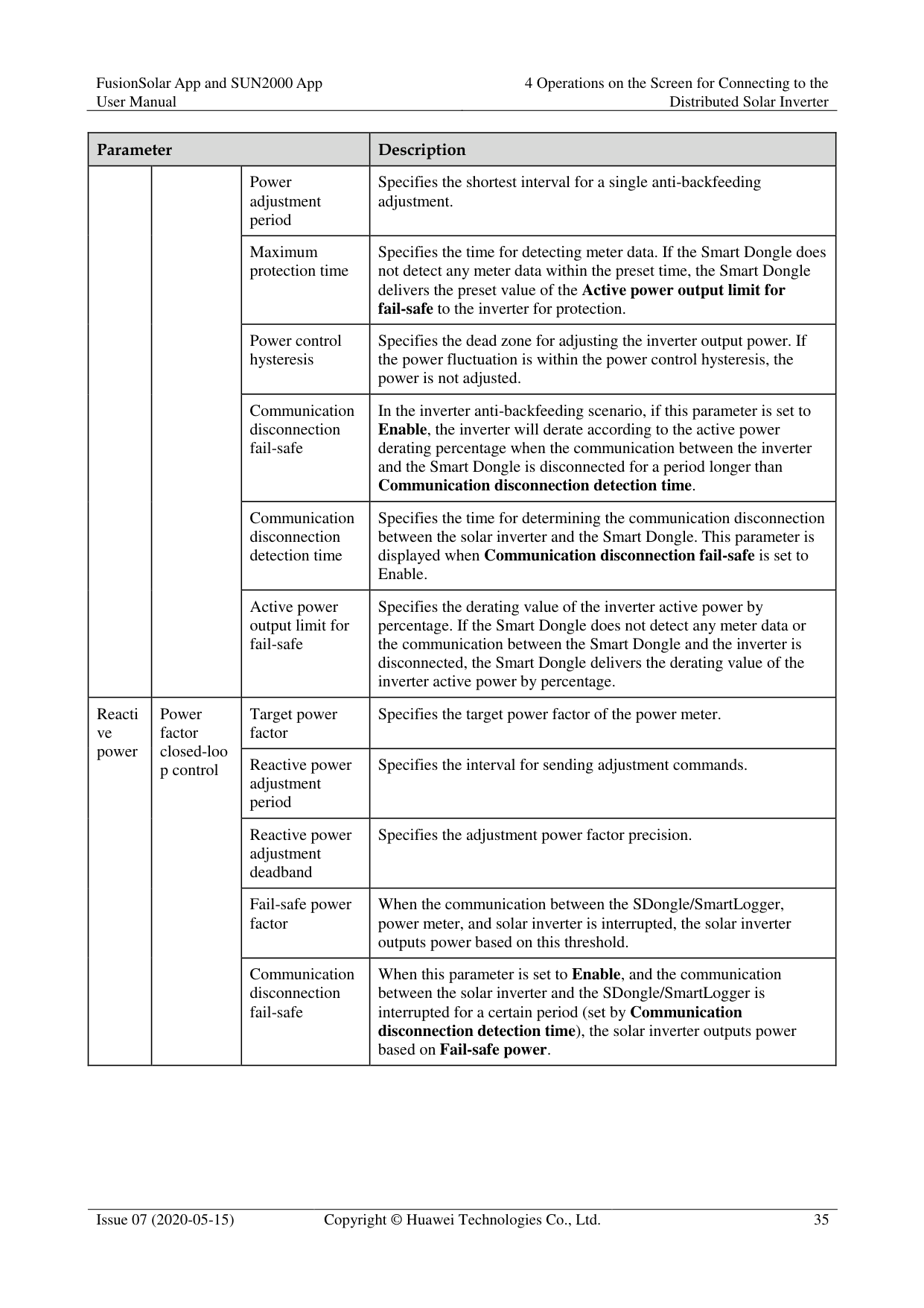
|Parameter|Parameter|Parameter|Description| |---|---|---|---| | | |Power adjustment period|Specifies the shortest interval for a single export limitation adjustment.| | | |Maximum protection time|Specifies the time for detecting power meter data. If the Dongle does not detect any power meter data within the preset time, the Dongle delivers the preset value of the Fail-safe power threshold to the solar inverter for protection.|
| | |Power control hysteresis|Specifies the dead zone for adjusting the inverter output power. If the power fluctuation is within the power control hysteresis, the power is not adjusted.| | | |Communication disconnection fail-safe|In the solar inverter export limitation scenario, if this parameter is set to Enable, the solar inverter will derate according to the active power derating percentage when the communication between the solar inverter and the Dongle is disconnected for a period longer than Communication disconnection detection time.| | | |Communication disconnection detection time|Specifies the time for determining the communication disconnection between the solar inverter and the Dongle.
This parameter is displayed only when Communication disconnection fail-safe is set to Enable.| | | |Active power output limit for fail-safe|Specifies the derating value of the solar inverter active power by percentage. If the Dongle does not detect any power meter data or the communication between the Dongle and the solar inverter is disconnected, the Dongle delivers the derating value of the solar inverter active power by percentage.| | |Grid connection with limited power (kW)|Closed-loop controller| For a single solar inverter, set Closed-loop controller to Inverter or SDongle/SmartLogger. − When Closed-loop controller is set to Inverter, the duration
is less than 2s. When Closed-loop controller is set to SDongle/SmartLogger, the duration is less than 5s.
For multiple solar inverters, Closed-loop controller can only be set to SDongle/SmartLogger. The duration is less than 5s.| | |Grid connection with limited power (kW)|Limitation mode| Total power indicates export limitation of the total power at the grid-tied point.
Single-phase power indicates export limitation of the power in each phase at the grid-tied point. (Note: COUNTIS E43 does not apply to this scenario.)| | |Grid connection with limited power (kW)|PV plant capacity|Specifies the total maximum active power in the solar inverter cascading scenario.| | |Grid connection with limited power (kW)|Maximum grid feed-in power (kW)|Specifies the maximum active power transmitted from the grid-tied point to the power grid.|
|Parameter|Parameter|Parameter|Description| |---|---|---|---| | | |Power adjustment period|Specifies the shortest interval for a single anti-backfeeding adjustment.| | | |Maximum protection time|Specifies the time for detecting meter data. If the Smart Dongle does not detect any meter data within the preset time, the Smart Dongle delivers the preset value of the Active power output limit for fail-safe to the inverter for protection.| | | |Power control hysteresis|Specifies the dead zone for adjusting the inverter output power. If the power fluctuation is within the power control hysteresis, the power is not adjusted.| | | |Communication disconnection fail-safe|In the inverter anti-backfeeding scenario, if this parameter is set to Enable, the inverter will derate according to the active power derating percentage when the communication between the inverter and the Smart Dongle is disconnected for a period longer than Communication disconnection detection time.| | | |Communication disconnection detection time|Specifies the time for determining the communication disconnection between the solar inverter and the Smart Dongle. This parameter is displayed when Communication disconnection fail-safe is set to Enable.| | | |Active power output limit for fail-safe|Specifies the derating value of the inverter active power by percentage. If the Smart Dongle does not detect any meter data or the communication between the Smart Dongle and the inverter is disconnected, the Smart Dongle delivers the derating value of the inverter active power by percentage.| | |Grid connection with limited power (%)|Closed-loop controller| For a single solar inverter, set Closed-loop controller to
Inverter or SDongle/SmartLogger.
When Closed-loop controller is set to Inverter, the duration is less than 2s.
When Closed-loop controller is set to SDongle/SmartLogger, the duration is less than 5s.
For multiple solar inverters, Closed-loop controller can only be set to SDongle/SmartLogger. The duration is less than 5s.| | |Grid connection with limited power (%)|Limitation mode| Total power indicates export limitation of the total power at the grid-tied point.
Single-phase power indicates export limitation of the power in each phase at the grid-tied point. (Note: COUNTIS E43 does not apply to this scenario.)| | |Grid connection with limited power (%)|PV plant capacity|Specifies the total maximum active power in the inverter cascading scenario.| | |Grid connection with limited power (%)|Maximum grid feed-in power (%)|Specifies the percentage of the maximum active power of the grid-tied point to the PV plant capacity.|
|Parameter|Parameter|Parameter|Description|
|---|---|---|---| | | |Power adjustment period|Specifies the shortest interval for a single anti-backfeeding adjustment.| | | |Maximum protection time|Specifies the time for detecting meter data. If the Smart Dongle does not detect any meter data within the preset time, the Smart Dongle delivers the preset value of the Active power output limit for fail-safe to the inverter for protection.| | | |Power control hysteresis|Specifies the dead zone for adjusting the inverter output power. If the power fluctuation is within the power control hysteresis, the power is not adjusted.| | | |Communication disconnection fail-safe|In the inverter anti-backfeeding scenario, if this parameter is set to Enable, the inverter will derate according to the active power derating percentage when the communication between the inverter and the Smart Dongle is disconnected for a period longer than Communication disconnection detection time.| | | |Communication disconnection detection time|Specifies the time for determining the communication disconnection between the solar inverter and the Smart Dongle. This parameter is displayed when Communication disconnection fail-safe is set to Enable.| | | |Active power output limit for fail-safe|Specifies the derating value of the inverter active power by percentage. If the Smart Dongle does not detect any meter data or the communication between the Smart Dongle and the inverter is disconnected, the Smart Dongle delivers the derating value of the inverter active power by percentage.| |Reacti ve power|Power factor closed-loo p control
|Target power factor|Specifies the target power factor of the power meter.| |Reacti ve power|Power factor closed-loo p control
|Reactive power adjustment period|Specifies the interval for sending adjustment commands.| |Reacti ve power|Power factor closed-loo p control
|Reactive power adjustment deadband|Specifies the adjustment power factor precision.| |Reacti ve power|Power factor closed-loo p control
|Fail-safe power factor|When the communication between the SDongle/SmartLogger, power meter, and solar inverter is interrupted, the solar inverter outputs power based on this threshold.| |Reacti ve power|Power factor closed-loo p control
|Communication disconnection fail-safe|When this parameter is set to Enable, and the communication between the solar inverter and the SDongle/SmartLogger is interrupted for a certain period (set by Communication disconnection detection time), the solar inverter outputs power based on Fail-safe power.|
|Parameter|Parameter|Parameter|Description| |---|---|---|---| | | |Communication disconnection detection time|Specifies the protection duration to determine whether the communication between the SDongle/SmartLogger and the solar inverter is interrupted.
This parameter is displayed only when Communication disconnection fail-safe is set to Enable.| | |No Output|N/A|If this parameter is set to No Output, no parameter is available.|
|Parameter|Parameter|Description| |---|---|---|
|Forcibl e charge/ dischar ge
|Charge/discharge power|Specifies the forced charge/discharge manually.| |Forcibl e charge/ dischar ge
|Forced charge/discharge power (kW)|Specifies the forced charge/discharge power.| |Forcibl e charge/ dischar ge
|Forced charge/discharge period (mins)|Specifies the forced charge/discharge duration.| |Forcibl e charge/ dischar ge
|Remaining charge/discharge time (mins)|Displays the remaining charge and discharge time, which cannot be set.| |Control mode|Control mode| If this parameter is set to Fixed charge/discharge, you can charge or discharge the batteries in the specified time period. A maximum of 10 time periods can be added.
If this parameter is set to Maximise self consumption and the solar inverter connects to a power meter, the solar inverter provides output power for local loads before feeding the remaining power to the power grid.
If this parameter is set to Time-of-use price, batteries discharge when the electricity price is high and charge when the electricity price is low. A maximum of 10 time periods can be added.
NOTE When setting Time-of-use price, ensure that the number of time periods is greater than or equal to 2, and that the number of tariffs is greater than or equal to 2.| |Feed power into grid|Feed power into grid|If this parameter is set to Enable, the batteries can be charged with the power supply from the power grid.
If this parameter is set to Disable before delivery, you must comply with the local regulations on charging the batteries with the power supply from the power grid.|

The duration for export limitation control is as follows:
############## For a single solar inverter, set Closed-loop controller to Inverter or SDongle/SmartLogger.
When Closed-loop controller is set to Inverter, the duration of export limitation control is less than 2s.
When Closed-loop controller is set to SDongle/SmartLogger, the duration is less than 5s if the controller is the SDongle. The duration is less than 2s if the controller is the SmartLogger.
############## For multiple solar inverters, Closed-loop controller can only be set to SDongle/SmartLogger.
The duration is less than 5s if the controller is the SDongle.
The duration is less than 2s if the controller is the SmartLogger.
5 Operations on the Screen for Connecting
to the Commercial Solar Inverter

The app screenshots provided in this chapter correspond to the SUN2000 app 3.2.00.005 version. The data on the screenshots is for reference only.
The document describes the operation method on the Android UI. The actual UI prevails.
The parameters displayed on the screen vary according to the solar inverter model connected to the app.
The 1000 V and 1500 V solar inverters have the maximum input voltages of 1000 V and 1500 V respectively. The 1100 V solar inverter refers to the one with the maximum input voltage of 1100 V or SUN2000-33KTL-US/36KTL-US/40KTL-US. The maximum input voltage can be queried from the product nameplate or the user manual.
Delivering a reset, factory reset, shutdown, or upgrade command to the solar inverters may cause power grid connection failure, which affects the energy yield.
Only professionals are allowed to set the grid parameters, protection parameters, feature parameters, power adjustment parameters, and grid-tied point control parameters of the solar inverters. If the grid parameters, protection parameters, and feature parameters are incorrectly set, the solar inverters may not connect to the power grid. If the power adjustment parameters and grid-tied point control parameters are incorrectly set, the solar inverters may not connect to the power grid as required. In these cases, the energy yield will be affected.
#### 5.1 Commercial Solar Inverter
######## Connection Modes
After the DC or AC side of a solar inverter is energized, the app can connect to the solar inverter in two methods:
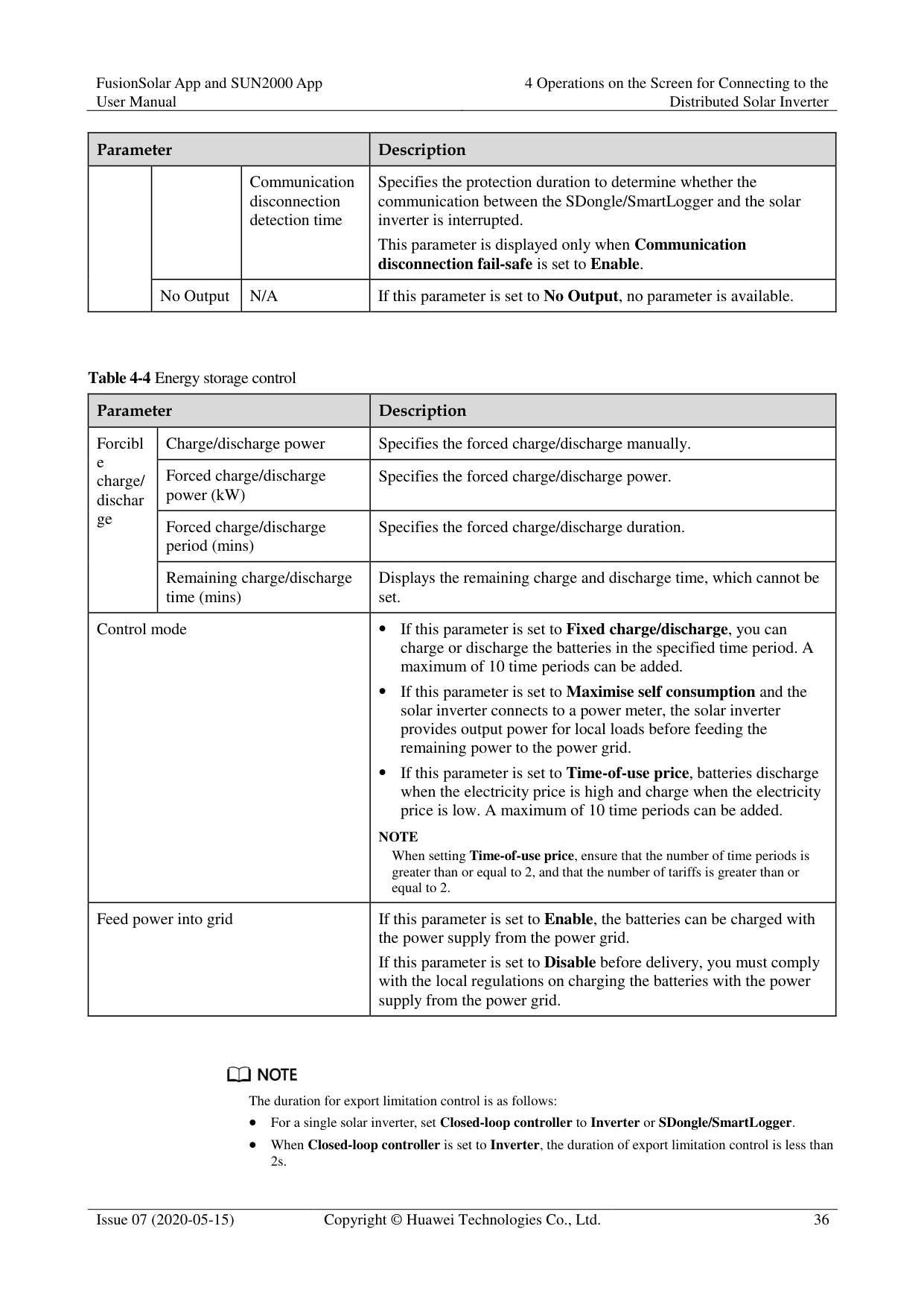
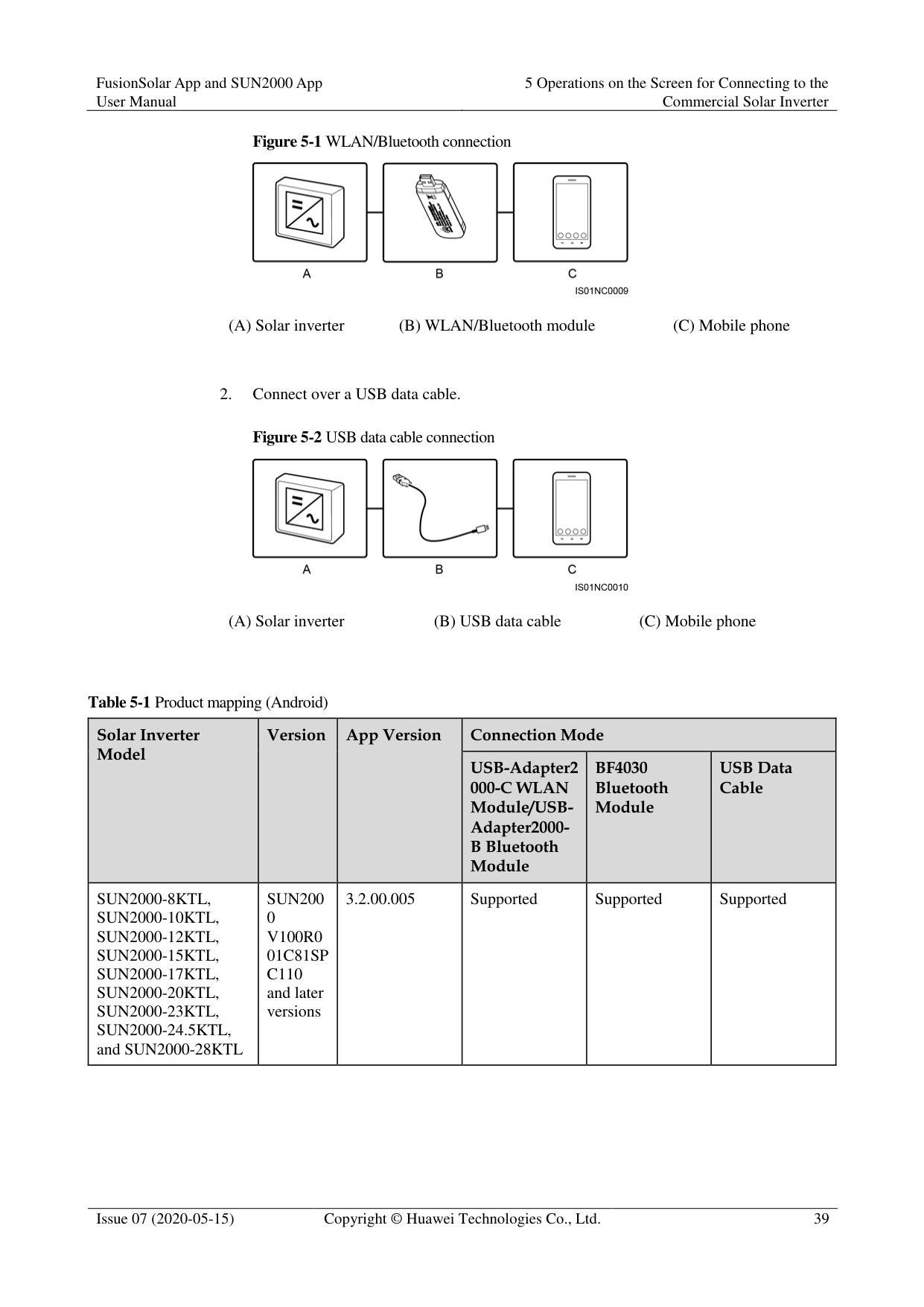
Figure 5-1 WLAN/Bluetooth connection

(A) Solar inverter (B) WLAN/Bluetooth module (C) Mobile phone
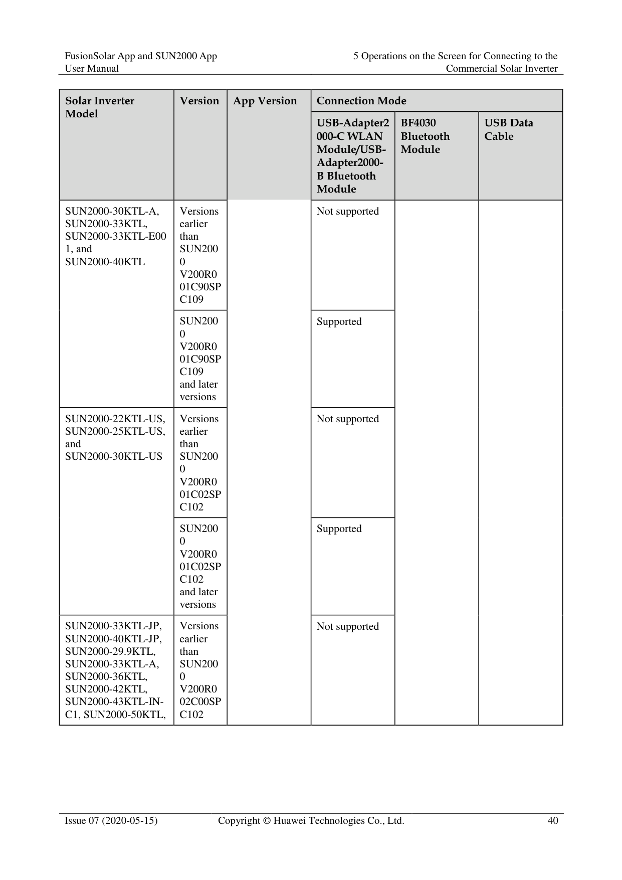
Figure 5-2 USB data cable connection

(A) Solar inverter (B) USB data cable (C) Mobile phone
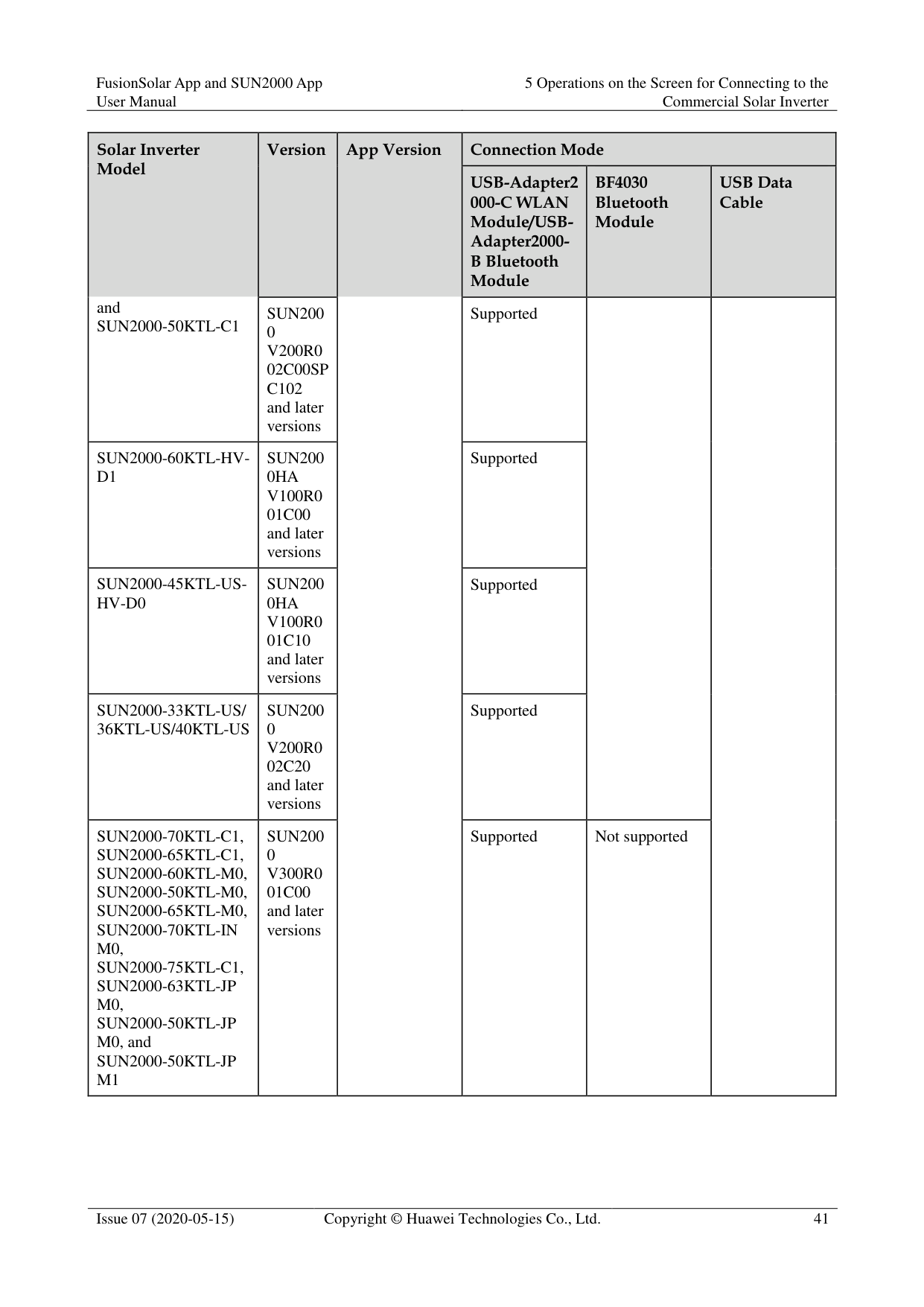
|Solar Inverter Model
|Version|App Version|Connection Mode|Connection Mode|Connection Mode| |---|---|---|---|---|---| |Solar Inverter Model
|Version|App Version|USB-Adapter2 000-C WLAN Module/USBAdapter2000B Bluetooth Module
|BF4030 Bluetooth Module
|USB Data Cable
| |SUN2000-8KTL, SUN2000-10KTL, SUN2000-12KTL, SUN2000-15KTL, SUN2000-17KTL, SUN2000-20KTL, SUN2000-23KTL, SUN2000-24.5KTL, and SUN2000-28KTL|SUN200
0 V100R0
01C81SP C110 and later versions
|3.2.00.005|Supported|Supported|Supported|
|Solar Inverter Model
|Version|App Version|Connection Mode|Connection Mode|Connection Mode| |---|---|---|---|---|---| |Solar Inverter Model
|Version|App Version|USB-Adapter2 000-C WLAN Module/USBAdapter2000B Bluetooth Module
|BF4030 Bluetooth Module
|USB Data Cable
| |SUN2000-30KTL-A, SUN2000-33KTL, SUN2000-33KTL-E00 1, and SUN2000-40KTL|Versions earlier than SUN200
0 V200R0
01C90SP C109
|App Version|Not supported| | | |SUN2000-30KTL-A, SUN2000-33KTL, SUN2000-33KTL-E00 1, and SUN2000-40KTL|SUN200
0 V200R0
01C90SP C109 and later versions
|App Version|Supported| | | |SUN2000-22KTL-US, SUN2000-25KTL-US, and SUN2000-30KTL-US|Versions earlier than SUN200
0 V200R0
01C02SP C102
|App Version|Not supported| | | |SUN2000-22KTL-US, SUN2000-25KTL-US, and SUN2000-30KTL-US|SUN200
0 V200R0
01C02SP C102 and later versions
|App Version|Supported| | | |SUN2000-33KTL-JP, SUN2000-40KTL-JP, SUN2000-29.9KTL, SUN2000-33KTL-A, SUN2000-36KTL,
SUN2000-42KTL,
SUN2000-43KTL-INC1, SUN2000-50KTL,
|Versions earlier than SUN200 0 V200R0 02C00SP C102|App Version|Not supported| | |
|Solar Inverter Model
and SUN2000-50KTL-C1|Version|App Version|Connection Mode|Connection Mode|Connection Mode| |---|---|---|---|---|---| |Solar Inverter Model
and SUN2000-50KTL-C1|Version|App Version|USB-Adapter2 000-C WLAN Module/USBAdapter2000B Bluetooth Module
|BF4030 Bluetooth Module
|USB Data Cable
| |Solar Inverter Model
and SUN2000-50KTL-C1|SUN200 0 V200R0 02C00SP C102 and later versions|App Version|Supported| | | |SUN2000-60KTL-HVD1|SUN200 0HA V100R0 01C00 and later versions|App Version|Supported| | | |SUN2000-45KTL-USHV-D0|SUN200 0HA V100R0 01C10 and later versions|App Version|Supported| | | |SUN2000-33KTL-US/ 36KTL-US/40KTL-US|SUN200 0 V200R0 02C20 and later versions|App Version|Supported| | | |SUN2000-70KTL-C1, SUN2000-65KTL-C1, SUN2000-60KTL-M0, SUN2000-50KTL-M0, SUN2000-65KTL-M0, SUN2000-70KTL-IN M0, SUN2000-75KTL-C1, SUN2000-63KTL-JP M0, SUN2000-50KTL-JP M0, and SUN2000-50KTL-JP M1|SUN200
0 V300R0
01C00 and later versions
|App Version|Supported|Not supported| |
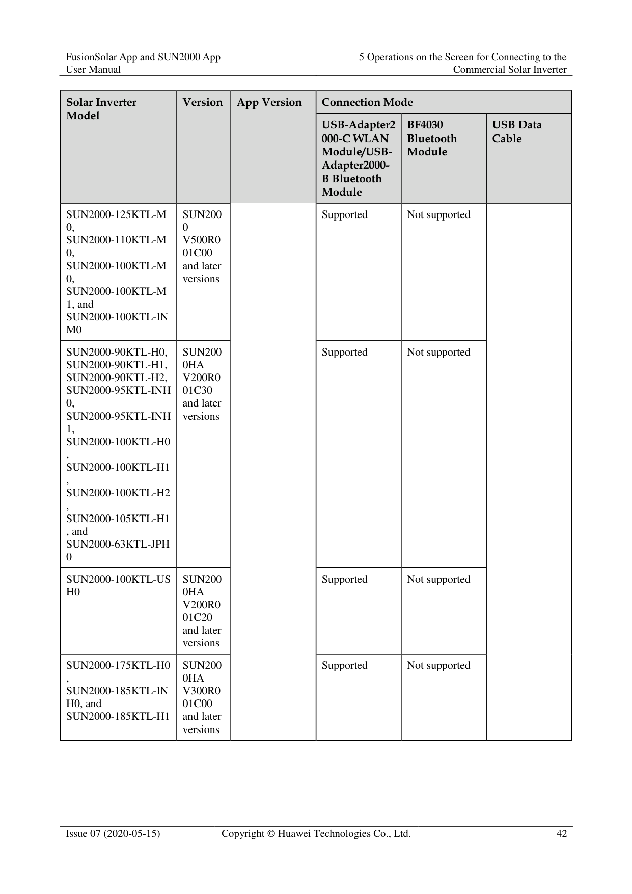
|Solar Inverter Model
|Version|App Version|Connection Mode|Connection Mode|Connection Mode| |---|---|---|---|---|---| |Solar Inverter Model
|Version|App Version|USB-Adapter2 000-C WLAN Module/USBAdapter2000B Bluetooth Module
|BF4030 Bluetooth Module
|USB Data Cable
| |SUN2000-125KTL-M 0, SUN2000-110KTL-M 0, SUN2000-100KTL-M
0, SUN2000-100KTL-M
1, and SUN2000-100KTL-IN M0
|SUN200
0 V500R0
01C00 and later versions
|App Version|Supported|Not supported| | |SUN2000-90KTL-H0,
SUN2000-90KTL-H1,
SUN2000-90KTL-H2, SUN2000-95KTL-INH
0, SUN2000-95KTL-INH
1,
SUN2000-100KTL-H0 ,
SUN2000-100KTL-H1 ,
SUN2000-100KTL-H2 , SUN2000-105KTL-H1 , and SUN2000-63KTL-JPH 0
|SUN200 0HA V200R0 01C30 and later versions|App Version|Supported|Not supported| |
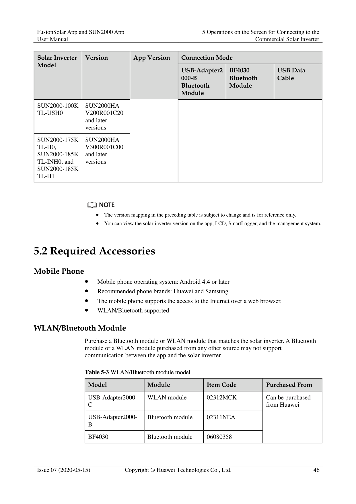
|SUN2000-100KTL-US H0|SUN200 0HA V200R0 01C20 and later versions|App Version|Supported|Not supported| | |SUN2000-175KTL-H0 , SUN2000-185KTL-IN H0, and SUN2000-185KTL-H1|SUN200 0HA V300R0 01C00 and later versions|App Version|Supported|Not supported| |
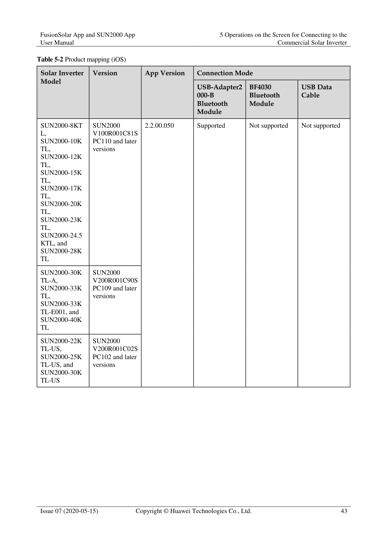
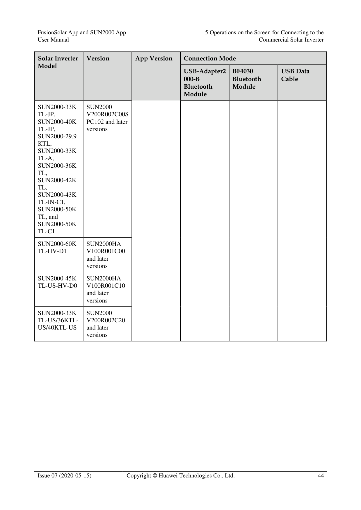
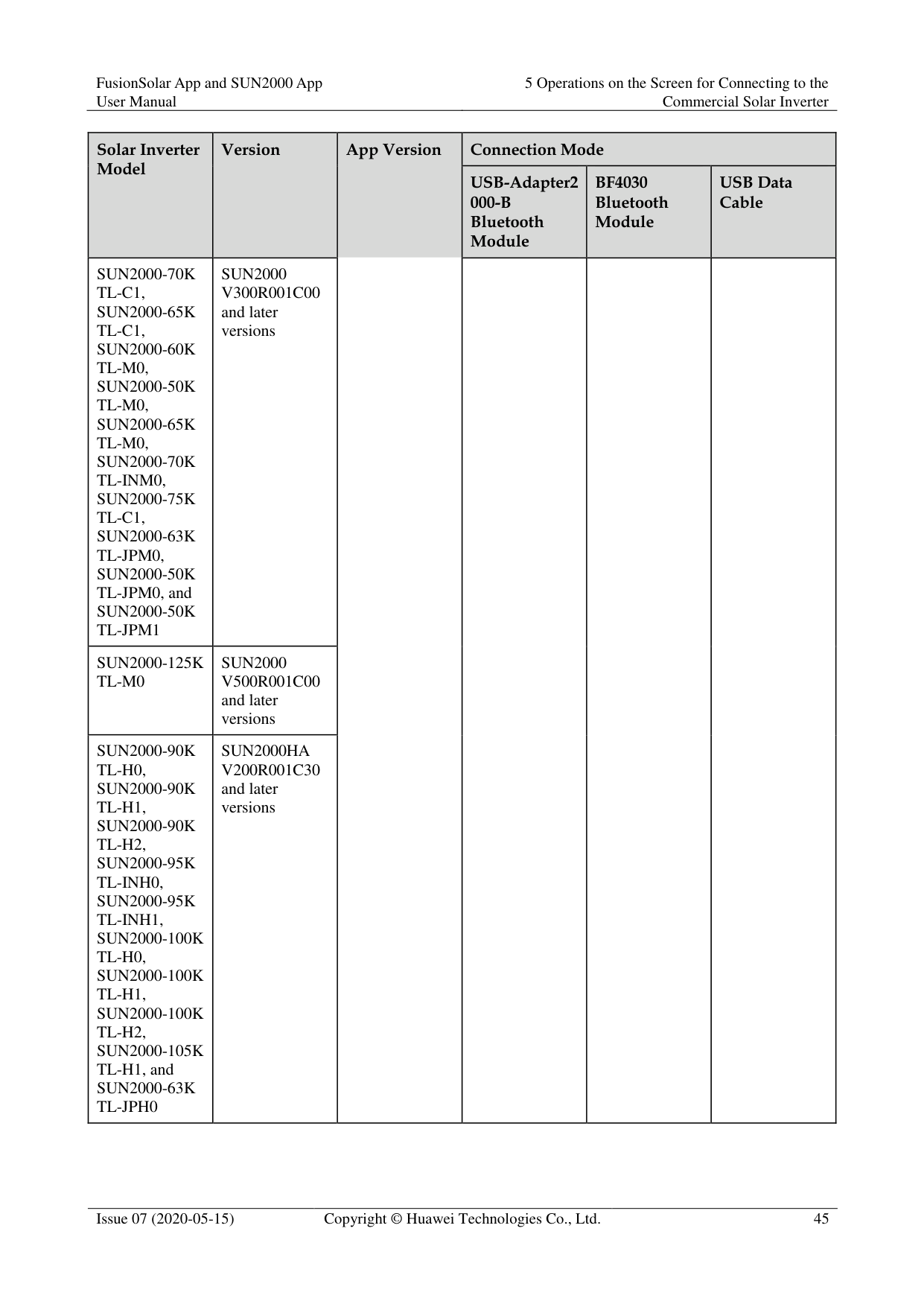
############ Table 5-2 Product mapping (iOS)
|Solar Inverter Model
|Version|App Version|Connection Mode|Connection Mode|Connection Mode| |---|---|---|---|---|---| |Solar Inverter Model
|Version|App Version|USB-Adapter2 000-B Bluetooth Module
|BF4030 Bluetooth Module
|USB Data Cable
| |SUN2000-8KT L, SUN2000-10K TL, SUN2000-12K TL, SUN2000-15K TL, SUN2000-17K TL, SUN2000-20K TL, SUN2000-23K TL, SUN2000-24.5 KTL, and SUN2000-28K TL|SUN2000 V100R001C81S PC110 and later versions|2.2.00.050
|Supported|Not supported|Not supported| |SUN2000-30K TL-A, SUN2000-33K TL, SUN2000-33K TL-E001, and SUN2000-40K TL|SUN2000 V200R001C90S PC109 and later versions|2.2.00.050
|Supported|Not supported|Not supported| |SUN2000-22K TL-US, SUN2000-25K TL-US, and SUN2000-30K TL-US|SUN2000 V200R001C02S PC102 and later versions|2.2.00.050
|Supported|Not supported|Not supported|
|Solar Inverter Model
|Version
|App Version|Connection Mode|Connection Mode|Connection Mode| |---|---|---|---|---|---| |Solar Inverter Model
|Version
|App Version|USB-Adapter2 000-B Bluetooth Module
|BF4030 Bluetooth Module
|USB Data Cable
| |SUN2000-33K TL-JP, SUN2000-40K TL-JP, SUN2000-29.9 KTL, SUN2000-33K TL-A, SUN2000-36K TL,
SUN2000-42K TL,
SUN2000-43K TL-IN-C1, SUN2000-50K TL, and SUN2000-50K TL-C1
|SUN2000 V200R002C00S PC102 and later versions|App Version| | | | |SUN2000-60K TL-HV-D1|SUN2000HA V100R001C00 and later versions|App Version| | | | |SUN2000-45K TL-US-HV-D0|SUN2000HA V100R001C10 and later versions|App Version| | | | |SUN2000-33K TL-US/36KTLUS/40KTL-US|SUN2000 V200R002C20 and later versions|App Version| | | |
|Solar Inverter Model
|Version
|App Version|Connection Mode|Connection Mode|Connection Mode| |---|---|---|---|---|---|
|Solar Inverter Model
|Version
|App Version|USB-Adapter2 000-B Bluetooth Module
|BF4030 Bluetooth Module
|USB Data Cable
| |SUN2000-70K TL-C1, SUN2000-65K TL-C1, SUN2000-60K TL-M0, SUN2000-50K TL-M0, SUN2000-65K TL-M0, SUN2000-70K TL-INM0, SUN2000-75K TL-C1, SUN2000-63K TL-JPM0, SUN2000-50K TL-JPM0, and SUN2000-50K TL-JPM1|SUN2000 V300R001C00 and later versions|App Version| | | | |SUN2000-125K TL-M0|SUN2000 V500R001C00 and later versions|App Version| | | | |SUN2000-90K
TL-H0, SUN2000-90K
TL-H1, SUN2000-90K
TL-H2, SUN2000-95K
TL-INH0, SUN2000-95K
TL-INH1, SUN2000-100K
TL-H0, SUN2000-100K
TL-H1, SUN2000-100K
TL-H2, SUN2000-105K TL-H1, and SUN2000-63K TL-JPH0
|SUN2000HA V200R001C30 and later versions|App Version| | | |
|Solar Inverter Model
|Version
|App Version|Connection Mode|Connection Mode|Connection Mode| |---|---|---|---|---|---| |Solar Inverter Model
|Version
|App Version|USB-Adapter2 000-B Bluetooth Module
|BF4030 Bluetooth Module
|USB Data Cable
| |SUN2000-100K TL-USH0|SUN2000HA V200R001C20 and later versions|App Version| | | | |SUN2000-175K
TL-H0, SUN2000-185K TL-INH0, and SUN2000-185K
TL-H1
|SUN2000HA V300R001C00 and later versions|App Version| | | |

The version mapping in the preceding table is subject to change and is for reference only.
You can view the solar inverter version on the app, LCD, SmartLogger, and the management system.
#### 5.2 Required Accessories
######## Mobile Phone
Mobile phone operating system: Android 4.4 or later Recommended phone brands: Huawei and Samsung The mobile phone supports the access to the Internet over a web browser.
######## WLAN/Bluetooth supported WLAN/Bluetooth Module
Purchase a Bluetooth module or WLAN module that matches the solar inverter. A Bluetooth module or a WLAN module purchased from any other source may not support communication between the app and the solar inverter.
Table 5-3 WLAN/Bluetooth module model
|Model|Module|Item Code|Purchased From| |---|---|---|---| |USB-Adapter2000C|WLAN module|02312MCK|Can be purchased from Huawei| |USB-Adapter2000B|Bluetooth module|02311NEA|Can be purchased from Huawei| |BF4030|Bluetooth module|06080358|Can be purchased from Huawei|
######## USB Data Cable
The USB data cable is delivered with the phone.

The port type of the USB data cable connected to the solar inverter is USB 2.0.
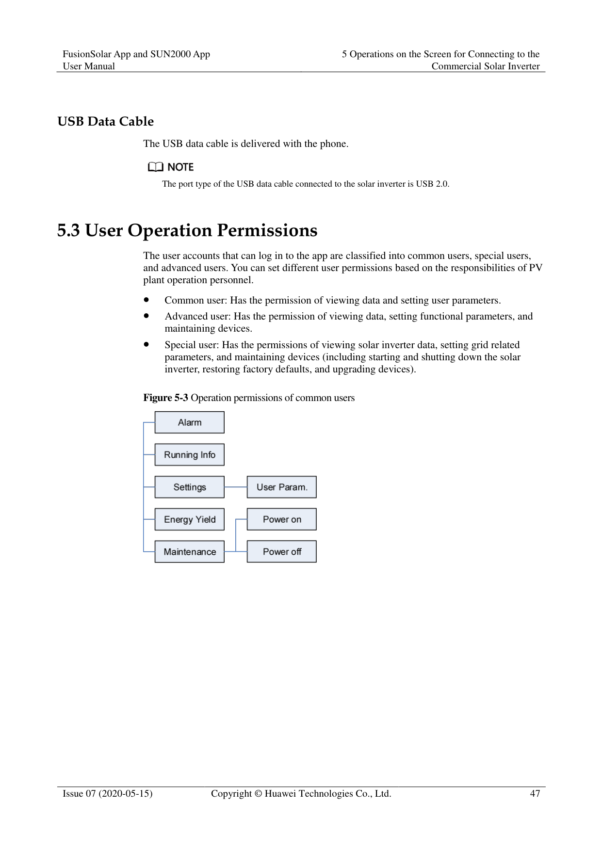
#### 5.3 User Operation Permissions
The user accounts that can log in to the app are classified into common users, special users, and advanced users. You can set different user permissions based on the responsibilities of PV plant operation personnel.
Common user: Has the permission of viewing data and setting user parameters.
Advanced user: Has the permission of viewing data, setting functional parameters, and maintaining devices.
Special user: Has the permissions of viewing solar inverter data, setting grid related parameters, and maintaining devices (including starting and shutting down the solar inverter, restoring factory defaults, and upgrading devices).

############ Figure 5-4 Operation permissions of advanced users


Support system is available for SUN2000 V200R001C91 and SUN2000 V200R001C93 of 1000 V solar inverters, all 1100 V solar inverters, and all 1500 V solar inverters.
Spot-check is available only to solar inverters using the Japanese grid code.
Start DC input detection is available only to 1500 V solar inverters.
AFCI self-test is available only to the solar inverters whose technical specifications contain AFCI on the product nameplate.
File save path is displayed only for the Android system.

#### 5.4 Login
######## Prerequisites
The DC or AC side of the solar inverter has been energized.
Connect over a WLAN/Bluetooth module:
Connect over a USB data cable:
######## Procedure
########### Figure 5-6 Connect

Code scanning: On the scanning screen, place the QR code or bar code of the WLAN/Bluetooth module in the scan frame. The device will be automatically connected after the code is identified.
########### Figure 5-7 Scan

Manual connection: On the scanning screen, tap Manual Connection and select a connection mode.
Figure 5-8 Manual connection

Select WLAN and connect to the corresponding WLAN in the WLAN connection list of the APP. The initial name of the WLAN hotspot is Adapter-WLAN module SN, and the initial password is Changeme.

Use the initial password upon first power-on and change it immediately after login. To ensure account security, change the password periodically and keep the new password in mind. Not changing the initial password may cause password disclosure. A password left unchanged for a long period of time may be stolen or cracked. If a password is lost, devices cannot be accessed. In these cases, the user is liable for any loss caused to the PV plant.
− Select Bluetooth, and tap Search for device. After a Bluetooth device is found, select the target Bluetooth device, and set up a connection. If the Bluetooth module is USB-Adapter2000-B, the connected Bluetooth device is named after last 8 digits of the SN barcode + HWAPP.
− Select USB, and tap OK to allow the app to access the USB accessory. After you select Use by default for this USB accessory, the message will not appear if you log in to the app again without removing the USB data cable.
########### Figure 5-9 Login


The login password is the same as that for the solar inverter connected to the app and is used only when the solar inverter connects to the app.
The initial passwords for Common User, Advanced User, and Special User are all
00000a.
Use the initial password upon first power-on and change it immediately after login. To ensure account security, change the password periodically and keep the new password in mind. Not changing the initial password may cause password disclosure. A password left unchanged for a long period of time may be stolen or cracked. If a password is lost, devices cannot be accessed. In these cases, the user is liable for any loss caused to the PV plant.
During the login, if five consecutive invalid password entries are made (the interval between two consecutive entries is less than 2 minutes), the account will be locked for 10 minutes. The password should consist of six characters.

If you log in to the SUN2000 app after the device powers on for the first time or factory defaults are restored, the Quick Settings screen will be displayed. If you do not set the basic parameters for the solar inverter on the Quick Settings screen, the screen is still displayed when you log in next time.
To set the basic parameters on the Quick Settings screen, switch to Advanced User. When you log in as Common User or Special User, enter the password of Advanced User in the dialog box that is displayed. After you confirm the password, go to the Quick Settings screen.
|Parameter|Description| |---|---| |Grid code|Set this parameter based on the grid code of the country or region where the SUN2000 is used and the SUN2000 application scenario.| |Date|Specifies the system date.| |Time|Specifies the system time.| |Baud rate (bps)|Set the RS485 baud rate to be consistent with the baud rate of the devices on the same bus.| |RS485 protocol| The solar inverter can connect to the upper-layer management unit over the Modbus RTU, SunSpec, or AVM protocol.
When the solar inverter connects to the support tracking system, only the Modbus RTU protocol is supported.| |Com address|Set the communications address of the SUN2000 when it connects to the upper-level management unit, which should not conflict with the addresses of other devices on the same bus.|
----End
#### 5.5 Screen Operations (Common User)
##### 5.5.1 QueryProcedure
Figure 5-10 Home screen

Tap an alarm record and view the alarm details.
Swipe right or left on the screen or tap either Active Alarm or Historical Alarm to display a list of active alarms or historical alarms.

Tap Sort by generated time to set the alarm sorting mode for active alarms or historical alarms.

Tap to set a time criterion. The historical alarms generated within the time segment are displayed.
Select the alarms that can be manually cleared, and tap Delete on the right of the alarm to manually clear the alarms.

Alarms that have been manually cleared can be viewed on the Historical Alarm screen.
Only the AFCI Self-Check Failure and DC Arc Fault alarms can be manually cleared. Only the products whose technical specifications contain AFCI supports manual alarm clearance.
----End
##### 5.5.2 Settings
######## Context
Due to permission restrictions, common users can set time parameters only for the solar inverters.
######## Procedure
Step 1 On the home screen, choose Settings > Time setting and set time parameters.
Figure 5-11 Time settings (common user)

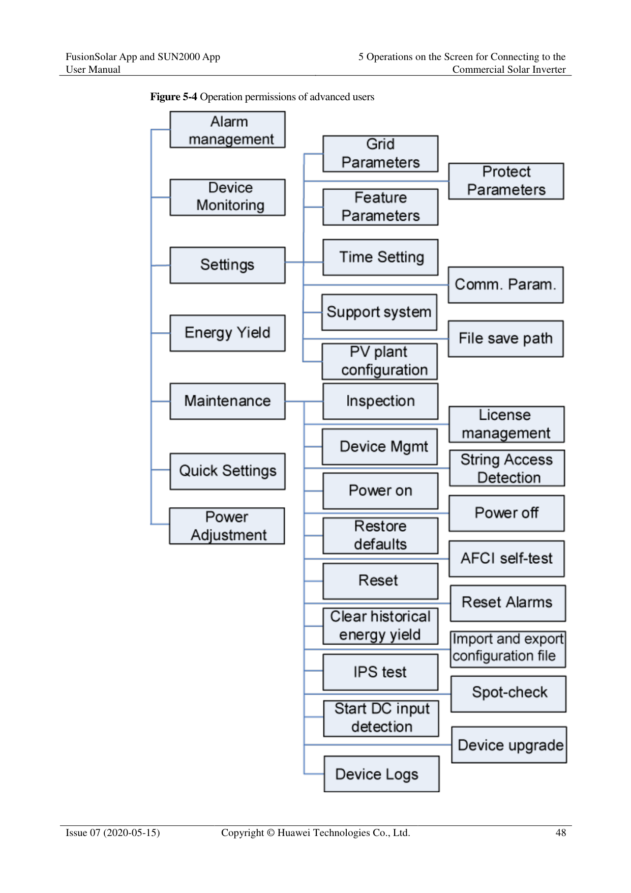
|Parameter|Description| |---|---| |Time setting|Specifies the system time.|

For a solar inverter that supports DST, if an advanced user enables DST, a common user can view DST data.
When an advanced user enables NTP time synchronization, common users can view the related data.
########### ----End
##### 5.5.3 Maintenance
####### 5.5.3.1 System Maintenance
Context
Because of permission restriction, common users can only turn on or off solar inverters. Procedure
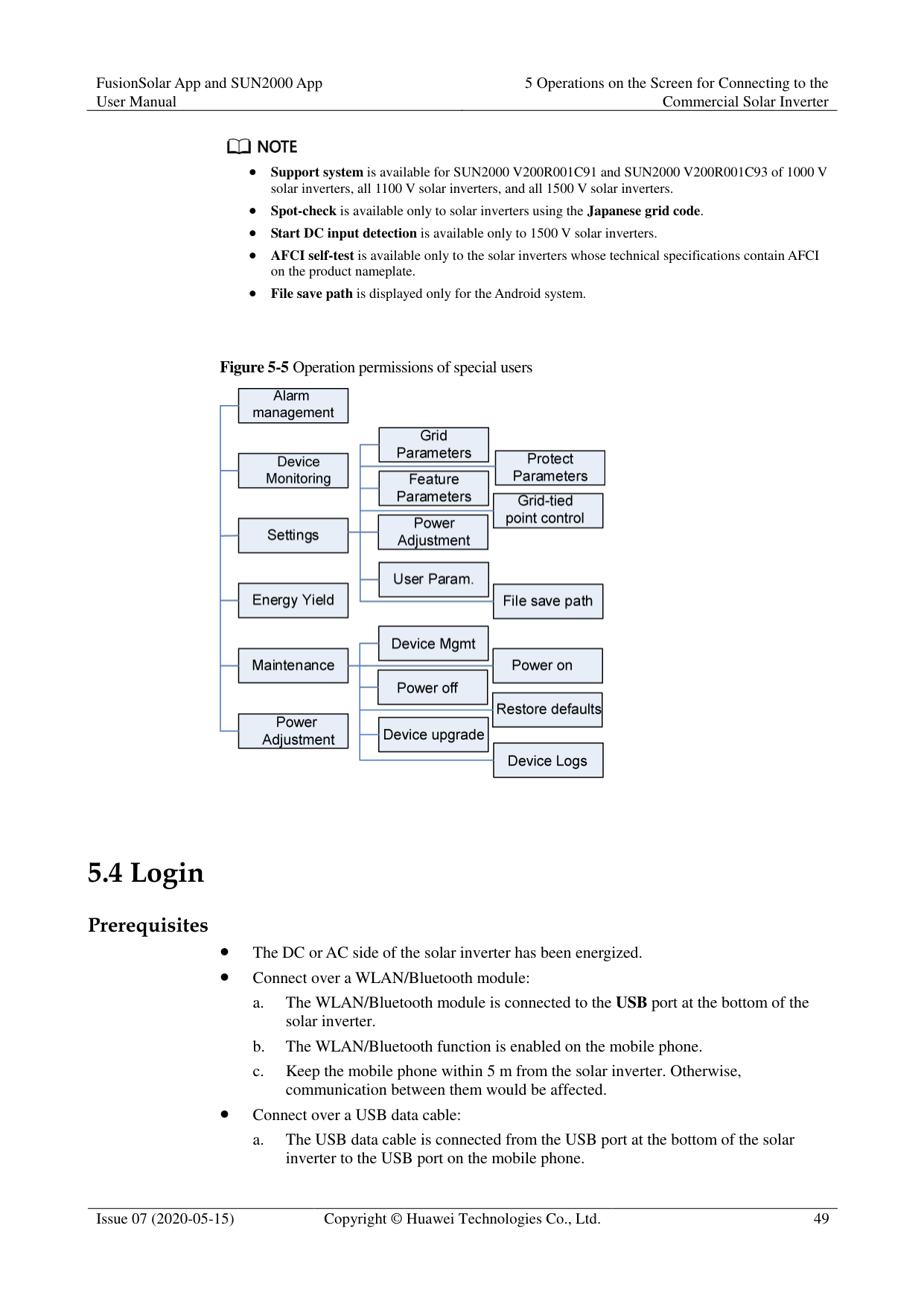
Figure 5-12 Maintenance


----End
####### 5.5.3.2 Feedback
######## Context
Users can provide feedback in text, pictures, and files.

Do not add private data. Procedure
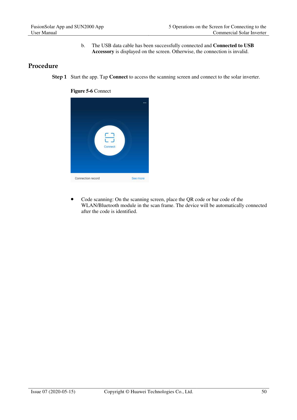

########### Figure 5-13 Feedback


----End
####### 5.5.3.3 Help
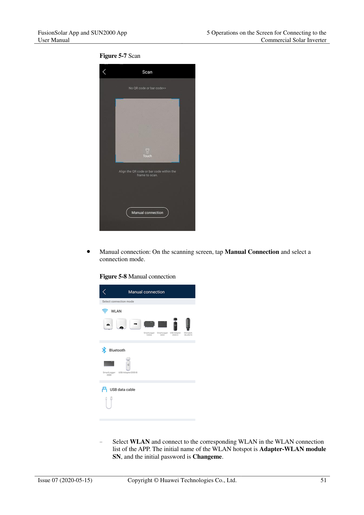
Context
If you have any questions when using an involved device or the app, search for solutions in the help information.
Procedure

Figure 5-14 Help

----End
####### 5.5.3.4 About
######## Context
You can query the app version, connected product model, SN, part number, firmware version, software version, technical support website, privacy policy (displayed only on the SUN2000 app), customer service contact information, and open source software policy.
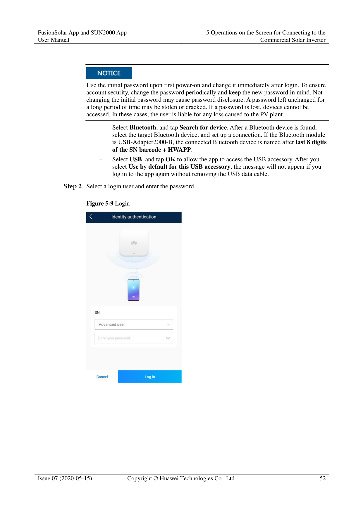

When the app starts for the first time after being downloaded or updated, the privacy policy is displayed. You can use the app only after agreeing to the privacy policy, and the privacy policy will no longer appear. If you do not agree to the privacy policy, the app exits, and the privacy policy is still displayed when you start the app next time until you agree to the privacy policy.
You can revoke the agreed privacy policy. Procedure

Figure 5-15 About

----End
#### 5.6 Screen Operations (Advanced User)
##### 5.6.1 QueryProcedure

Tap an alarm record and view the alarm details.
Swipe right or left on the screen or tap either Active Alarm or Historical Alarm to display a list of active alarms or historical alarms.

Tap Sort by generated time to set the alarm sorting mode for active alarms or historical alarms.

Tap to set a time criterion. The historical alarms generated within the time segment are displayed.
Select the alarms that can be manually cleared, and tap Delete on the right of the alarm to manually clear the alarms.

Alarms that have been manually cleared can be viewed on the Historical Alarm screen.
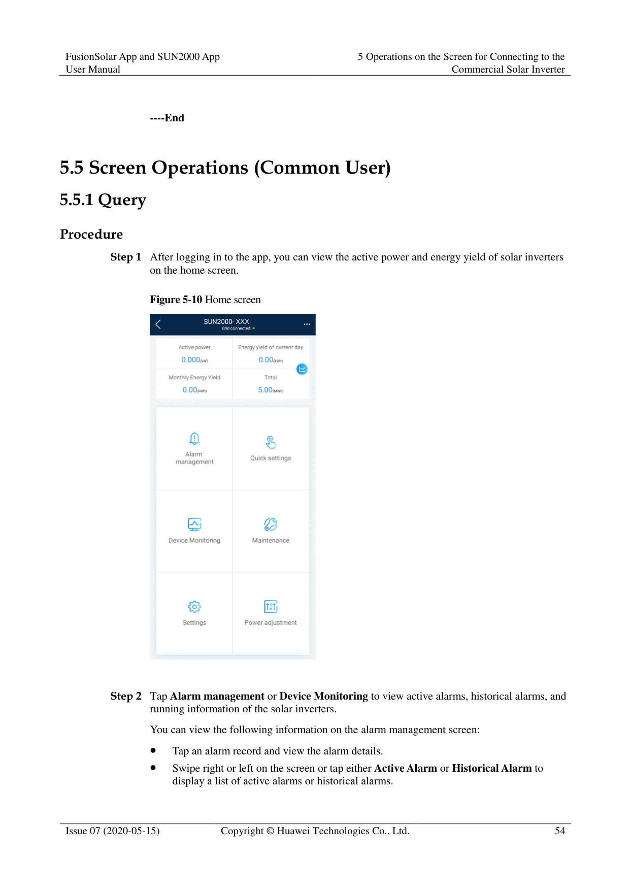
Only the AFCI Self-Check Failure and DC Arc Fault alarms can be manually cleared. Only the products whose technical specifications contain AFCI supports manual alarm clearance.
########### ----End
##### 5.6.2 Quick Settings
Context
Due to permission restrictions, only advanced users can quickly set up the solar inverter. Procedure
Figure 5-17 Quick settings


The screenshot of Quick settings provided in this document is for reference only. The actual screens prevail.
----End
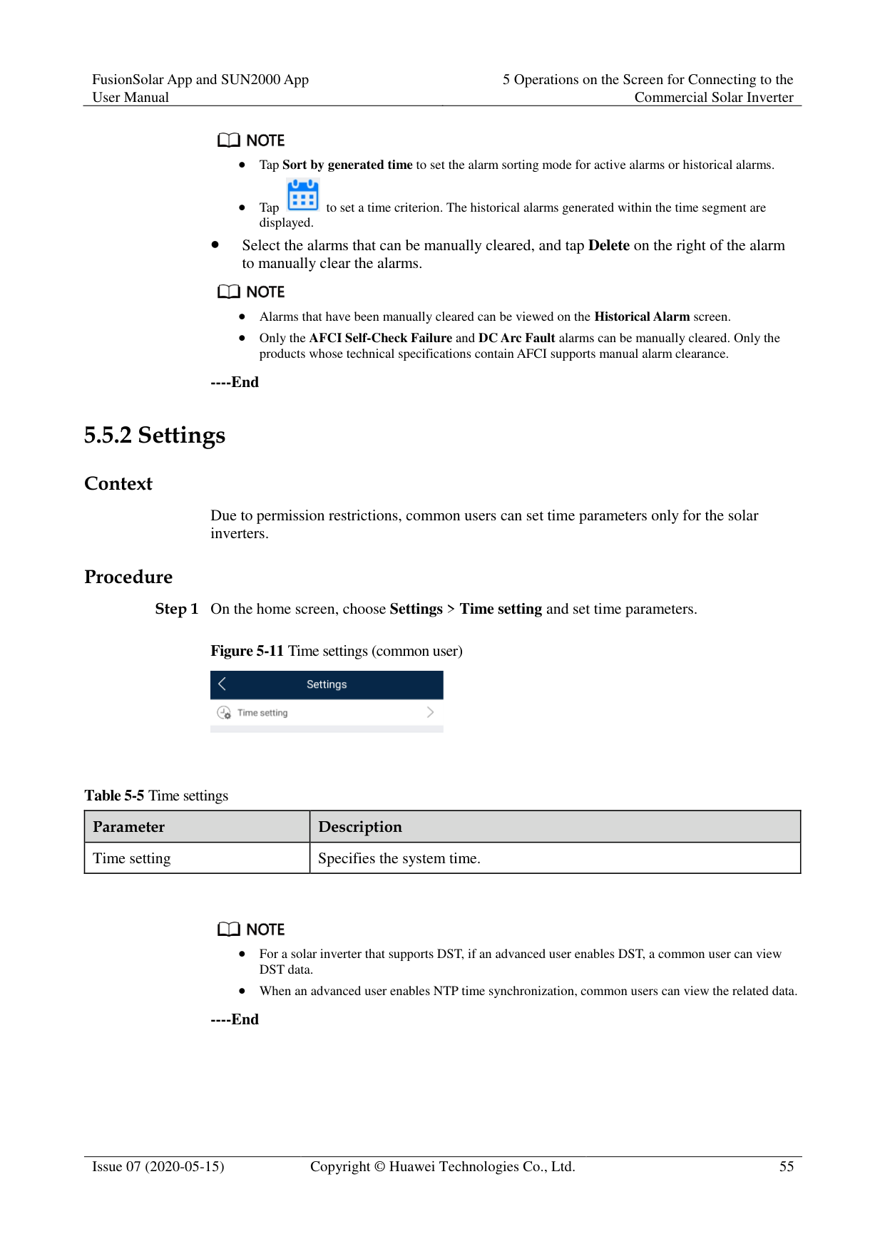
##### 5.6.3 Settings
On the home screen, an advanced user can tap Settings to set power grid, protection, and feature parameters for the solar inverter.
Figure 5-18 Settings (advanced user)


The configurable solar inverter parameters vary with the solar inverter model and grid code. The displayed parameters prevail. The parameter list provided in this section includes all configurable parameters.
The parameter ranges vary with the device model. The listed ranges are for reference only.
The parameter names, value ranges, and default values are subject to change. The actual display prevails.
####### 5.6.3.1 Setting Grid Parameters
######## Procedure
Step 1 On the home screen, choose Settings > Grid Parameters to access the parameter setting
screen.
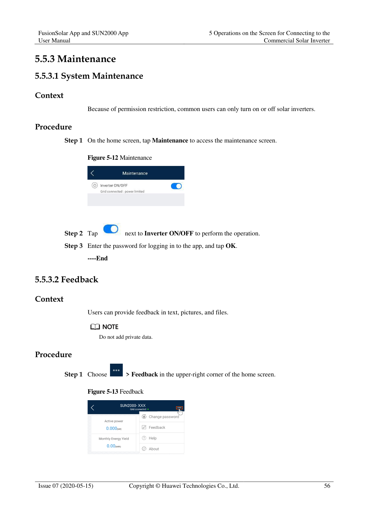
Figure 5-19 Grid Parameters (advanced user)

For details about how to set the parameters, see A Commercial Smart Inverters Parameters.
########### ----End
####### 5.6.3.2 Setting Protection Parameters
Procedure
Step 1 On the home screen, choose Settings > Protection Parameters to access the parameter
setting screen.
Figure 5-20 Protection parameters (advanced user)

For details about how to set the parameters, see A Commercial Smart Inverters Parameters.
----End
####### 5.6.3.3 Setting Feature Parameters

######## Procedure
Step 1 On the home screen, choose Settings > Feature Parameters to access the parameter setting
screen.
Figure 5-21 Feature parameters (advanced user)

For details about how to set the parameters, see A Commercial Smart Inverters Parameters.
########### ----End
####### 5.6.3.4 Time setting
######## Procedure
Step 1 On the home screen, choose Settings > Time setting and set user parameters.
Figure 5-22 Time setting (advanced user)

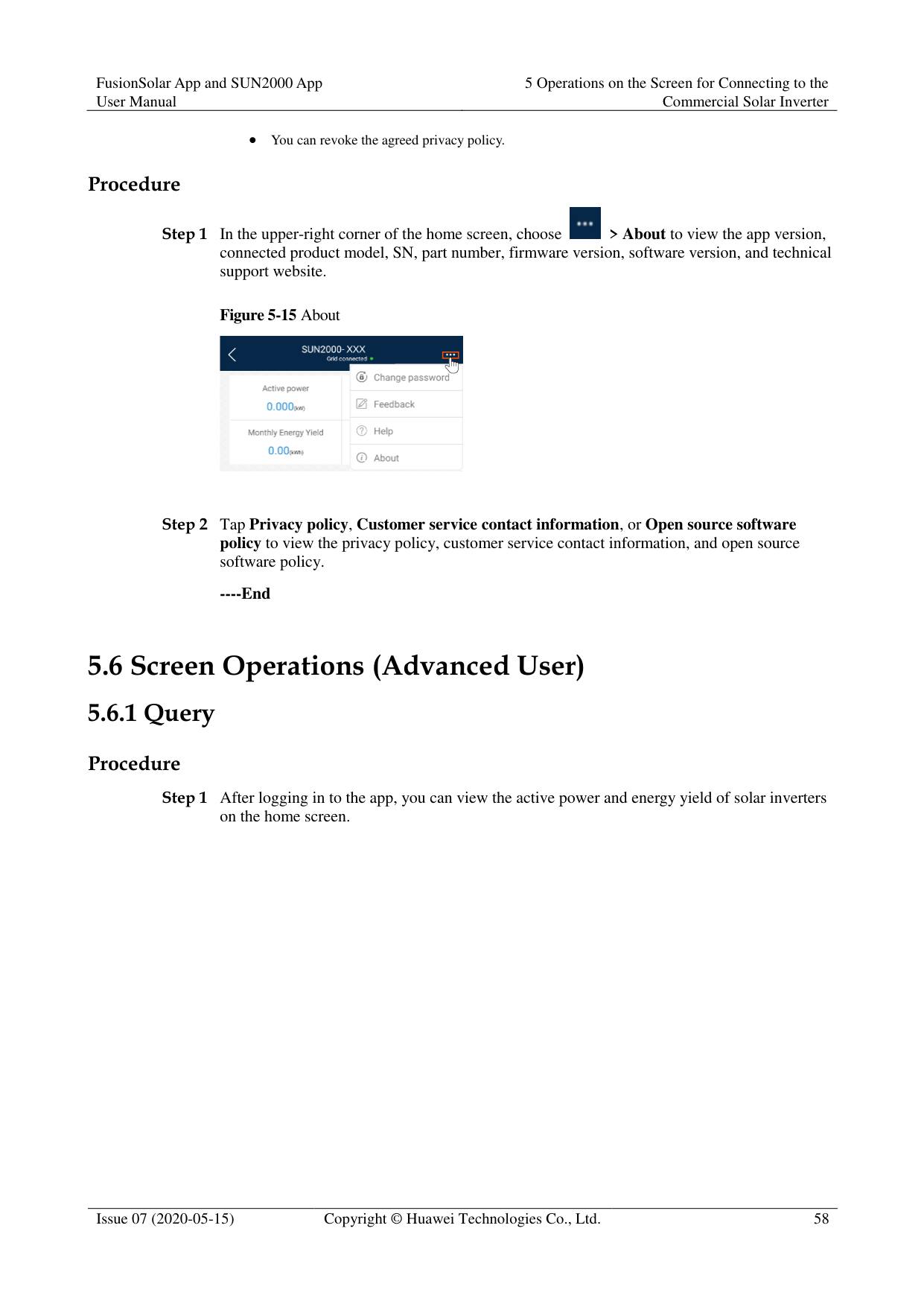
|Parameter|Description| |---|---| |Time zone|Specifies the time zone.| |Time setting|Specifies the system date and time.| |Daylight saving time|Specifies whether to enable daylight saving time (DST).| |Offset time|Specifies the DST offset.| |Start date|Specifies the DST offset start date.| |Start time|Specifies the DST offset start time.| |End date|Specifies the DST offset end date.| |End time|Specifies the DST offset end time.| |Clock source|Specifies whether to enable NTP time synchronization.| |NTP server address|Specifies the NTP server IP address or domain name.|
|Parameter|Description| |---|---| |NTP server port|Specifies the server port.| |NTP time synchronization interval|Specifies the NTP time synchronization interval.| |Last NTP synchronization status|Display the result of the last synchronization of the NTP server.| |Last NTP synchronization time|Set the time of the last synchronization of the NTP server.|
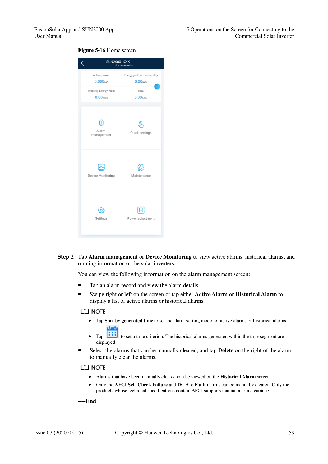

You can set DST parameters and NTP parameters.
----End
####### 5.6.3.5 Setting Communications Parameters
######## Procedure
Step 1 On the home screen, choose Settings > Comm. Parameters to access the parameter setting
screen.
Figure 5-23 Communications parameters

|Parameter|Description| |---|---| |RS485_1|Set RS485 communications parameters. RS485 CAN Resistor is available only to the 1000 V solar inverters. This
parameter is set to by default. If signals are distorted or the communication is of poor quality because of an overlong communications cable, set the parameter to for the last solar inverter in the daisy chain.

| |RS485_2|Set RS485 communications parameters. This parameter is displayed only for the solar inverters that can connect to the RS485 slave device.|
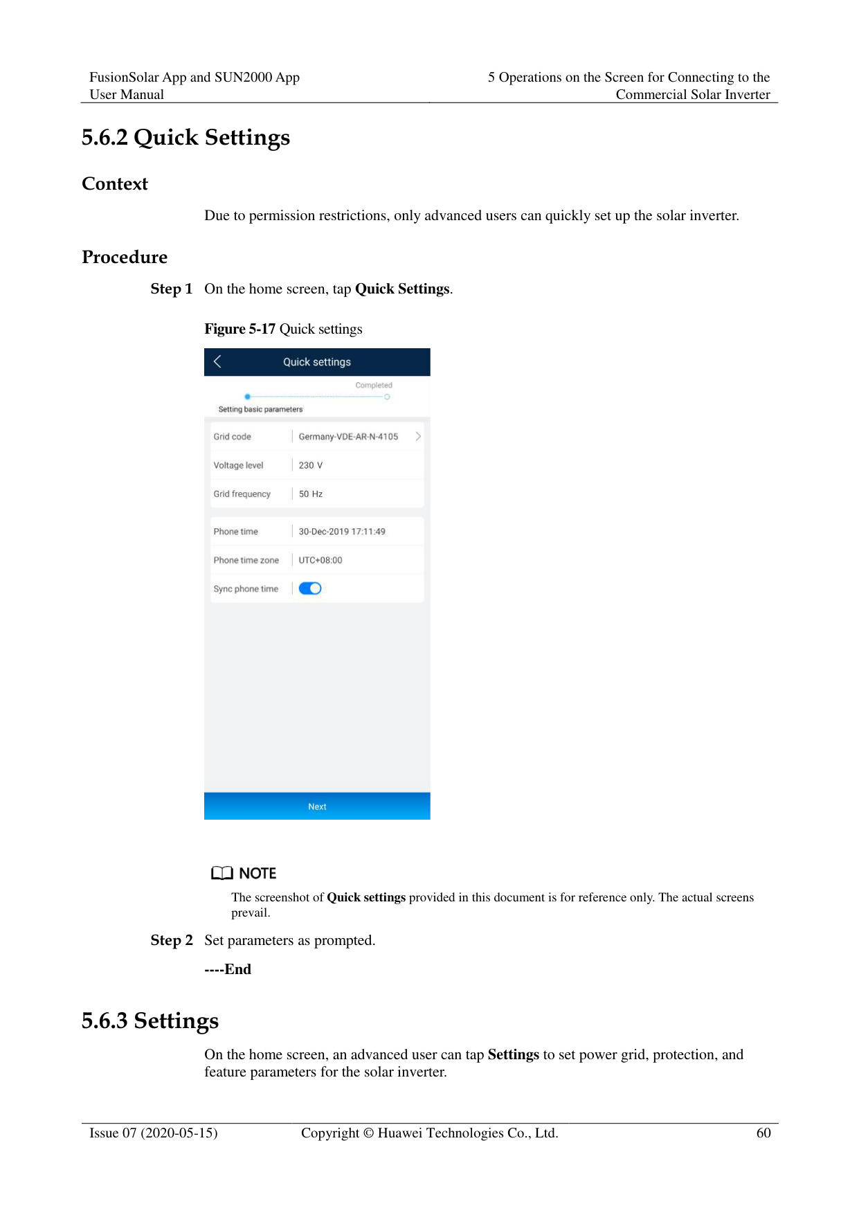
|Parameter|Description| |---|---| |MBUS|Set MBUS communications parameters. This parameter is displayed only for the solar inverters that support the MBUS function.| |Ethernet|Set Ethernet parameters. NOTE
When DHCP is set to , the IP address, Subnet mask, and Gateway of the solar inverter are automatically allocated.

When DHCP is set to , you can manually set the IP address, Subnet

mask, and Gateway.| |Management system|Set management system parameters. This parameter is displayed only for the solar inverters that can connect to the SDongle. NOTE
If SSL encryption is set to , data will be transmitted without being encrypted, which may pose security risks. Therefore, exercise caution when setting this parameter.
| |4G/GPRS|Set 4G/GPRS communications parameters. This parameter is displayed only for the solar inverters that can connect to the SDongle.| |WLAN|Setting WLAN communications parameters This parameter is displayed only for the solar inverters that can connect to the SDongle.| |Dongle|Set Dongle communications parameters. This parameter is displayed only for the solar inverters that can connect to the SDongle.|

You can check whether the solar inverter supports the MBUS or SDongle function by viewing the product nameplate on it.
----End
####### 5.6.3.6 Setting a Tracking System
######## Context
This function is available to the 1000 V (SUN2000 V200R001C91 and SUN2000 V200R001C93 only), 1100 V, and 1500 V solar inverters. The support parameters vary depending on the controller manufacturer. Set parameters based on site requirements. The following screenshots are based on the same scenario.
######## Procedure
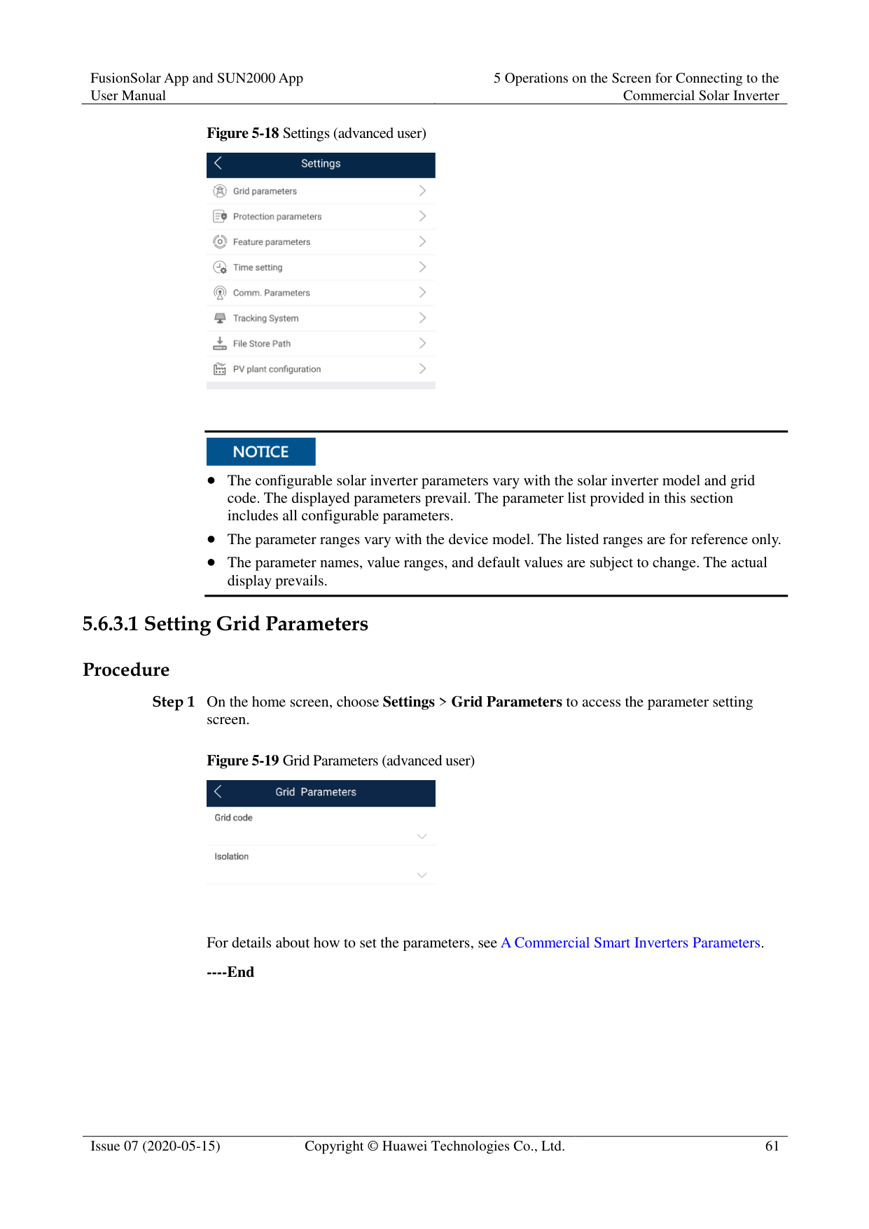

Step 2 Swipe left on the screen to access the support status screen, tap a support, and set parameters
for the support.

----End
####### 5.6.3.7 Setting a File Save Path
######## Prerequisite
This function is available only on the Android system. Context
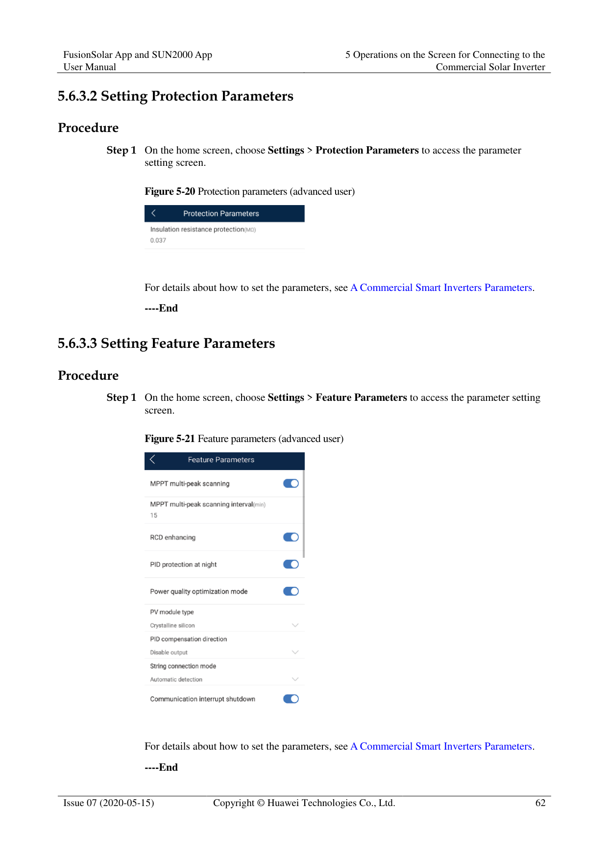
You can modify the save path for operation logs and solar inverter logs and export logs from the path.
######## Procedure
Figure 5-26 File save path

----End
##### 5.6.4 Power Adjustment
######## Context
Due to permission restrictions, advanced users support the setting of power adjustment, which can set the grid-connected control parameters of the solar inverter.
######## Procedure
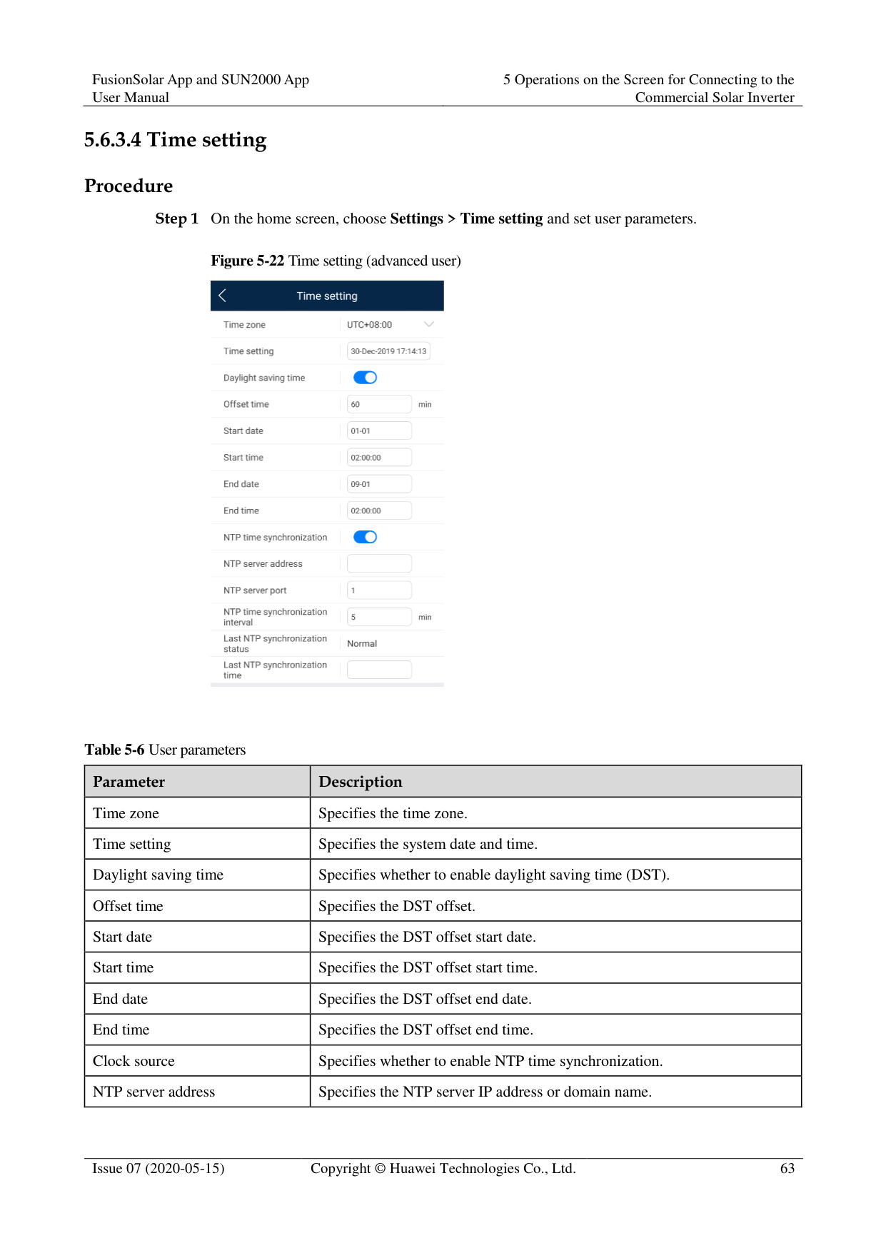
Figure 5-27 Power adjustment


When setting the Grid-tied point control parameters, you need to enter the APP login password.
----End
##### 5.6.5 Maintenance
An advanced user can tap Maintenance on the home screen to inspect, turn on, or turn off the solar inverters and detect the DC input.
Figure 5-28 Maintenance screen (advanced user)

####### 5.6.5.1 Device Inspection
######## Context
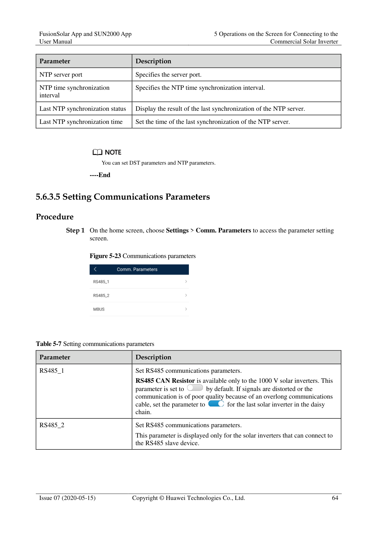
After a solar inverter is put into use, it should be inspected periodically to detect any potential risks and problems.
######## Procedure

Step 2 Choose Inspection type, tap in the upper-right corner of the screen to start solar

inverter inspection.

----End
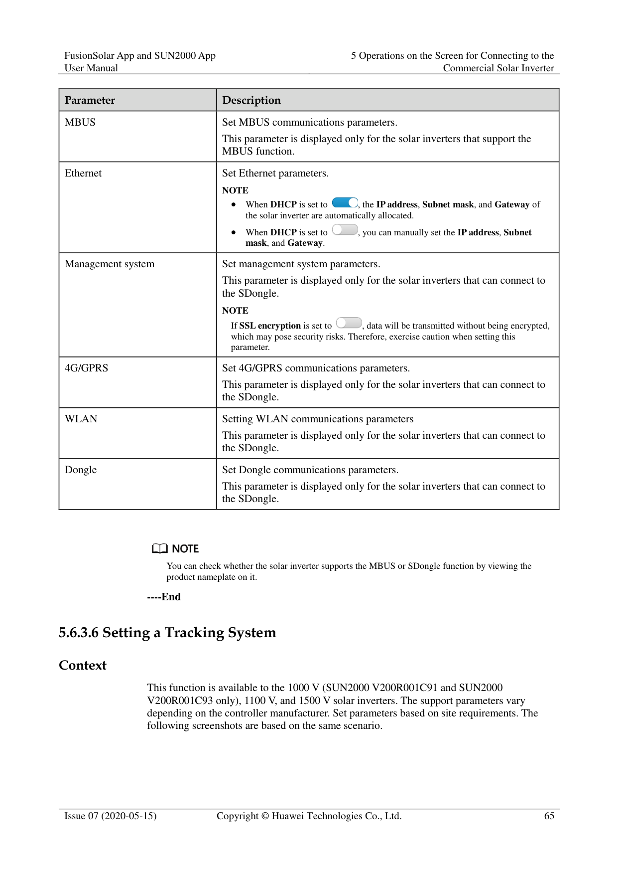
####### 5.6.5.2 License Management
######## Context
The License management screen allows an advanced user to view the solar inverter certificate and obtain the status of the certificate.
######## Procedure
Step 1 On the home screen, choose Maintenance > License management to access the license
management screen.
Figure 5-31 License management


When License status is Normal, you can revoke the license through the drop-down list box in the upper-right corner.
When License status is Deregistered, you can export and view the license revocation code.
When License status is No license, you can load the license through the drop-down list box in the upper-right corner.
----End
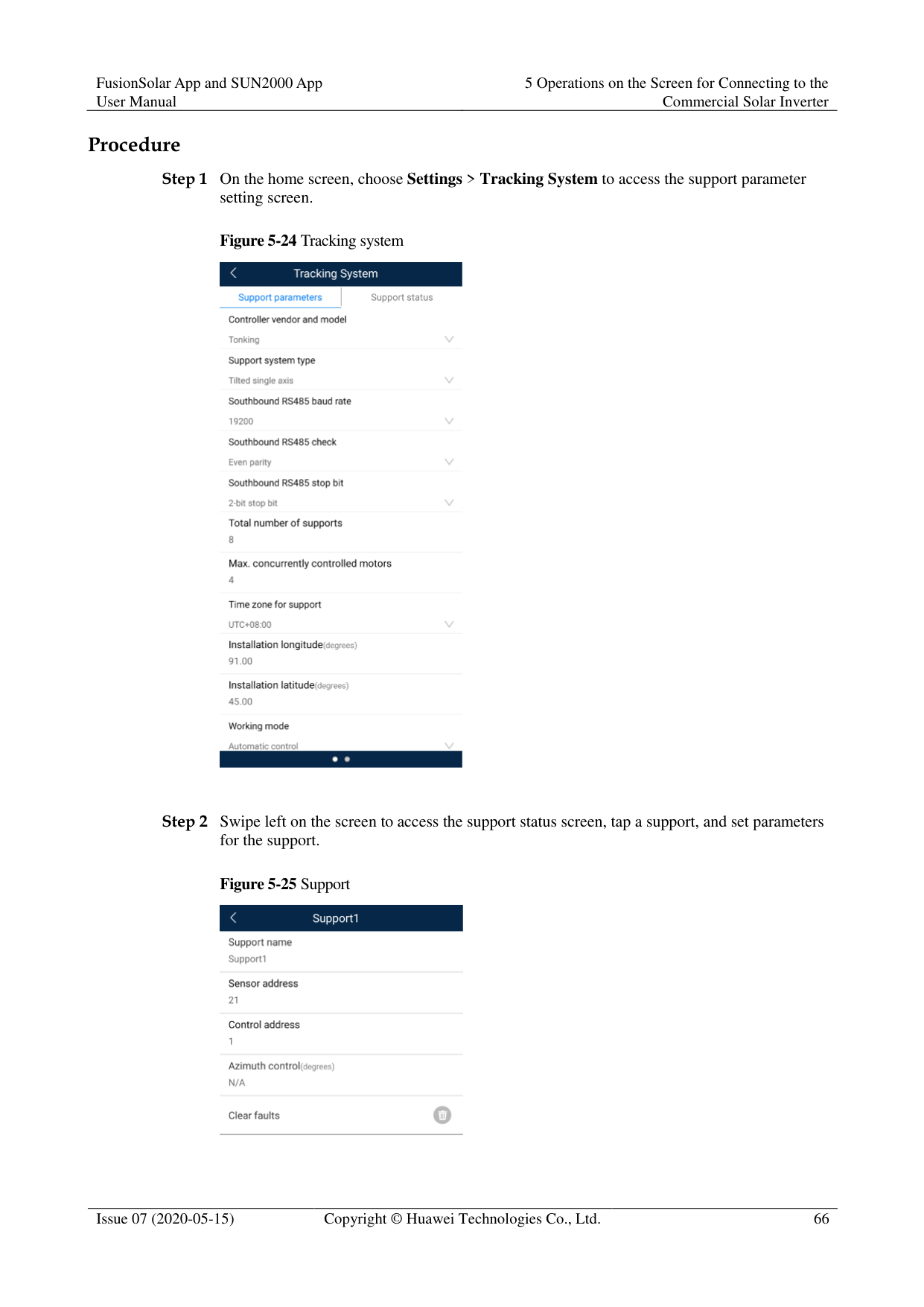
####### 5.6.5.3 Add/Delete Device
########### Step 1 On the home screen, choose Maintenance > Device Mgmt to access the Add/Delete device
screen.
Figure 5-32 Add/Delete device

Tap + to add a power meter.
|Parameter|Description| |---|---| |Model|Set this parameter to the corresponding meter model. NOTE
Select an appropriate power meter based on the application scenario. The device model is subject to change. The actual product prevails.
Set the power meter model correctly. Otherwise, the power meter function may be unavailable.|
|Parameter|Description| |---|---| |Device address|Set this parameter to the communication address of the power meter.| |Current change ratio| Set this parameter to 1 if the power meter uploads the primary value.
Set this parameter based on the actual transformer ratio if the power meter uploads the secondary value.|
After a power meter is added, tap it to view and modify the power meter parameters. To delete the power meter, touch and hold it.
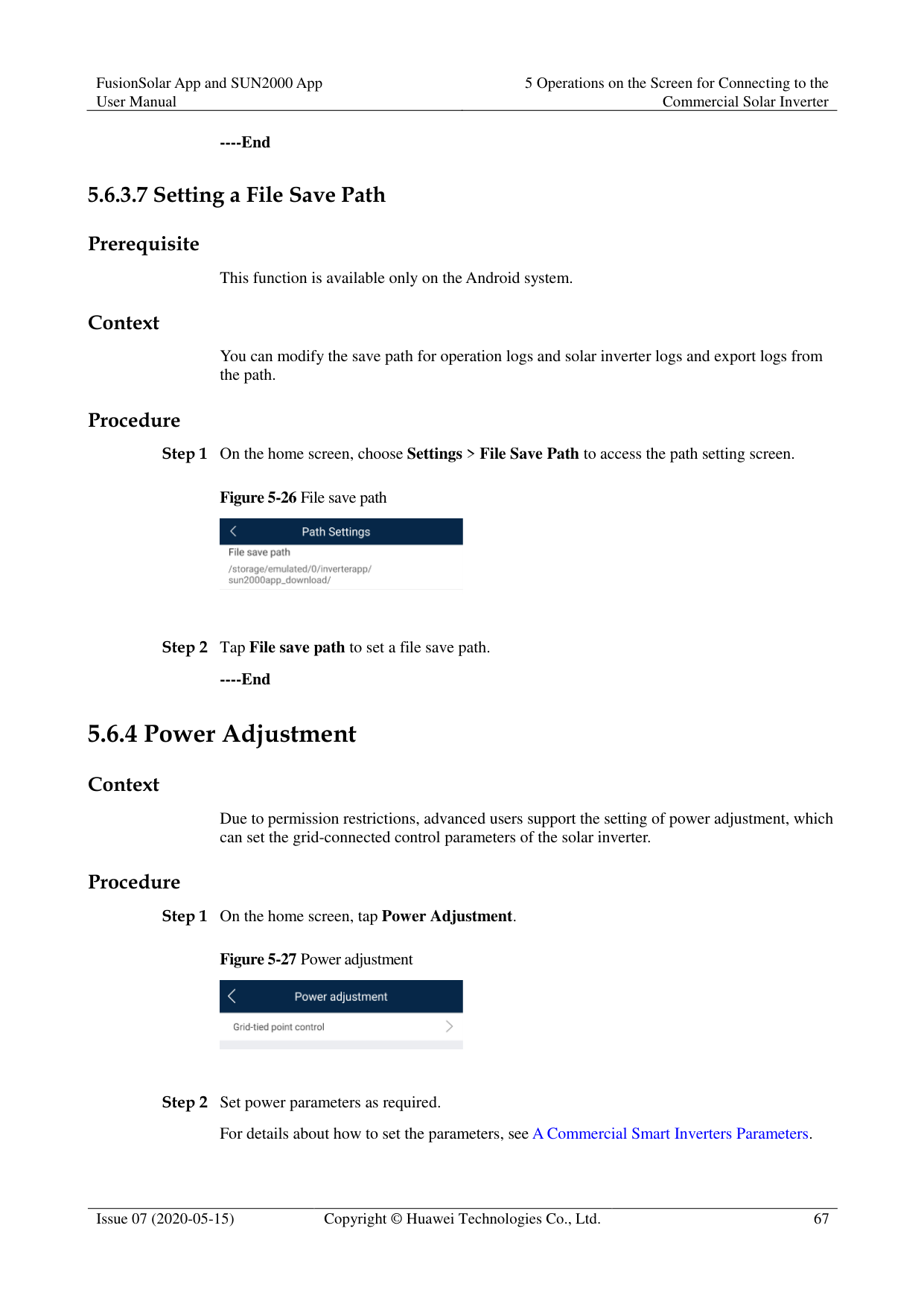
----End
####### 5.6.5.4 PV String Access Detection
######## Context
PV string access detection applies to large-scale commercial ground PV plants with PV
strings facing the same direction. In AC or DC power limiting scenarios:
If the PV string access type has not been identified, String Access Detection will be displayed as Not connected. The PV string access type can be identified only when the solar inverters restore to the non-power limiting state and the current of all connected PV strings reaches the startup current.
− If the PV string access type has been identified, when a certain PV string connected to the 2-in-1 terminals is lost, no alarm will be generated. If a certain PV string connected to the 2-in-1 terminals is restored, the access type cannot be identified. You can determine whether both 2-in-1 PV strings are restored only when the PV string current reaches Startup current for 2-in-1 detection.
After setting the parameters, on the home screen, choose Running Info. > Details to
check whether the PV string access status is normal. Procedure
########### Step 1 On the home screen, choose Maintenance > String Access Detection and set PV string
access detection parameters.
Figure 5-33 String access detection
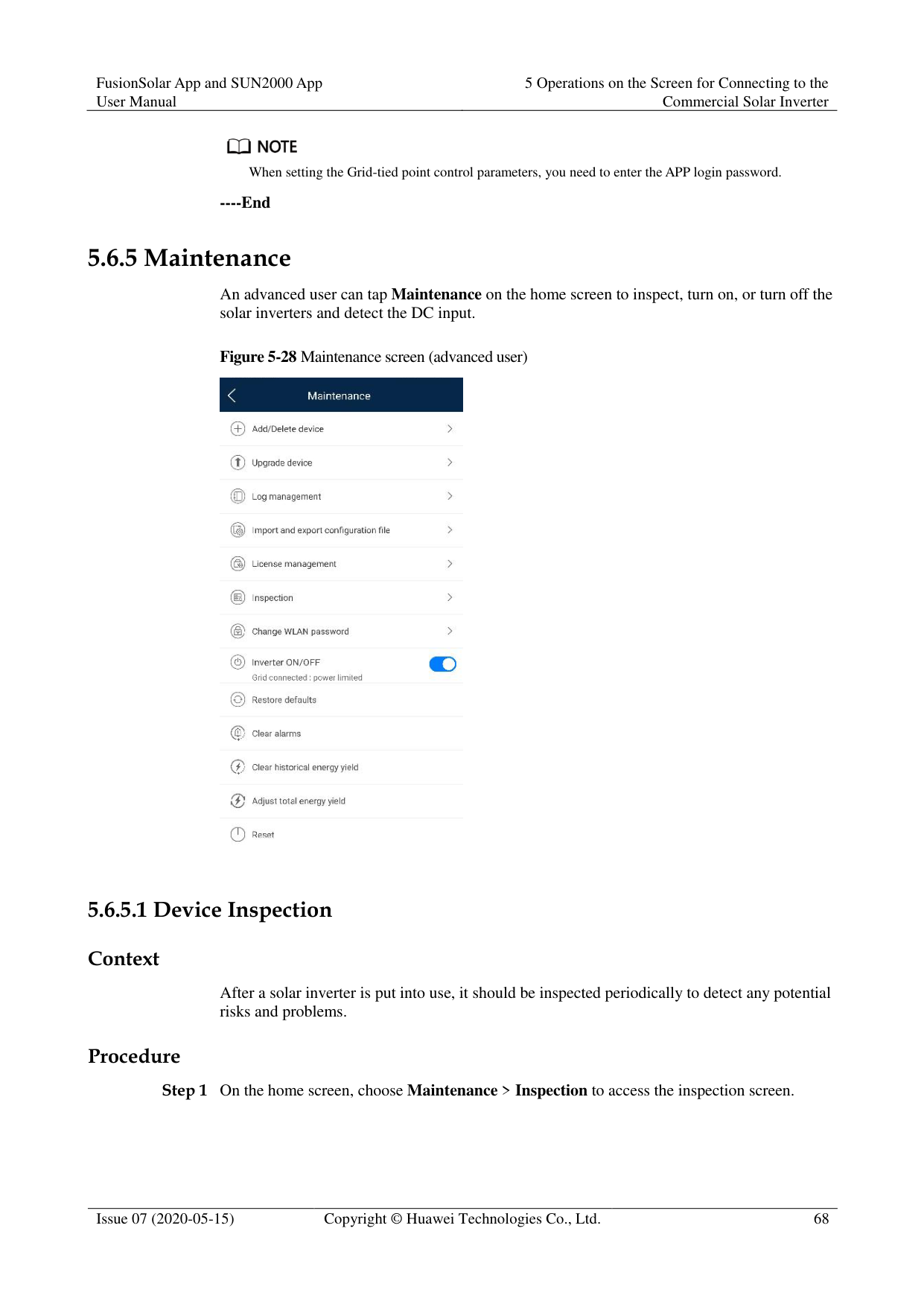

Table 5-8 PV string access detection
|Parameter|Description| |---|---| |String Access Detection|String Access Detection is set to Disable by default. After solar inverters are connected to the power grid, set String Access Detection to Enable.| |Startup current (A)|When the current of all connected PV strings reaches the preset value, the PV string access detection function is enabled.
NOTE
Startup current setting rules:
Startup current = Isc (Stc) x 0.6 (rounded up). For details about Isc (Stc), see the PV module nameplate.
Default startup current (5 A): applicable to the scenarios where the short-circuit current Isc (Stc) is greater than 8 A for the monocrystalline and polycrystalline PV modules.| |Startup current for 2-in-1 detection (A)|When the current of a PV string reaches Startup current for 2-in-1 detection, the PV string is automatically identified as 2-in-1 string. You are advised to retain the default settings.| |PV string N access type NOTE
N is the DC input terminal number of the solar inverter.|Set this parameter based on the type of the PV string connected to DC input terminal N of the solar inverter.
You are advised to retain the default value. If the value is incorrectly set, the PV string access type may be incorrectly identified and alarms may be generated by mistake for the PV string access status.|
----End
####### 5.6.5.5 Startup and ShutdownProcedure

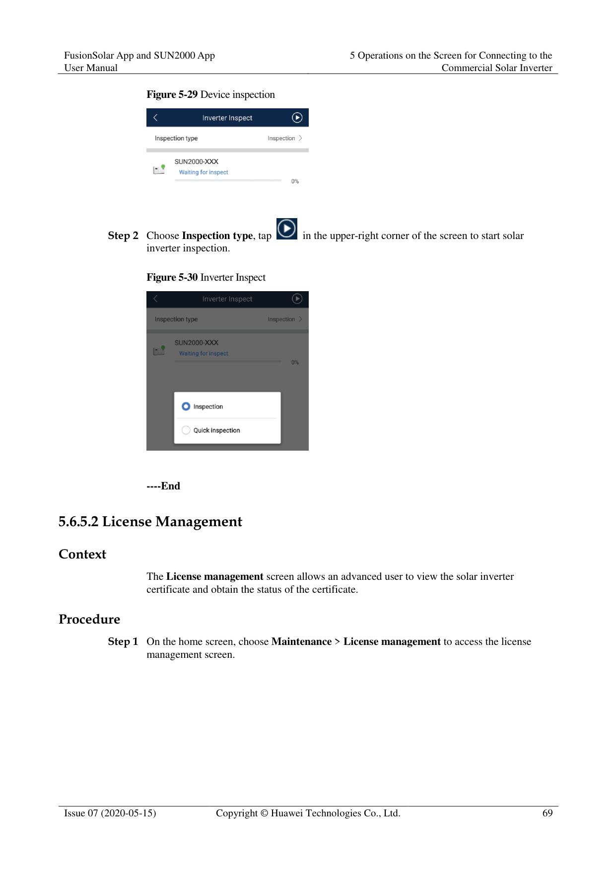
----End
####### 5.6.5.6 Restoring Factory SettingsContext

Perform this operation with caution because all configured parameters except the current date, time, baud rate, and address will be restored to their factory default values. This operation will not affect operating information, alarm records, or system logs.
Procedure
----End
####### 5.6.5.7 Performing an AFCI Self-Check
Context
The AFCI self-check function is available only to the solar inverter model marked with -US. Procedure
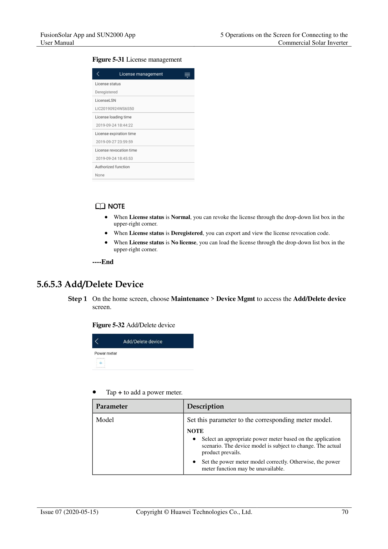
----End
####### 5.6.5.8 Resetting a Solar Inverter
######## Context
The solar inverter automatically shuts down and restarts after reset.
----End
####### 5.6.5.9 Clearing Alarms
Context
After alarms are reset, all active alarms and historical alarms of the solar inverter connected to the app will be cleared.
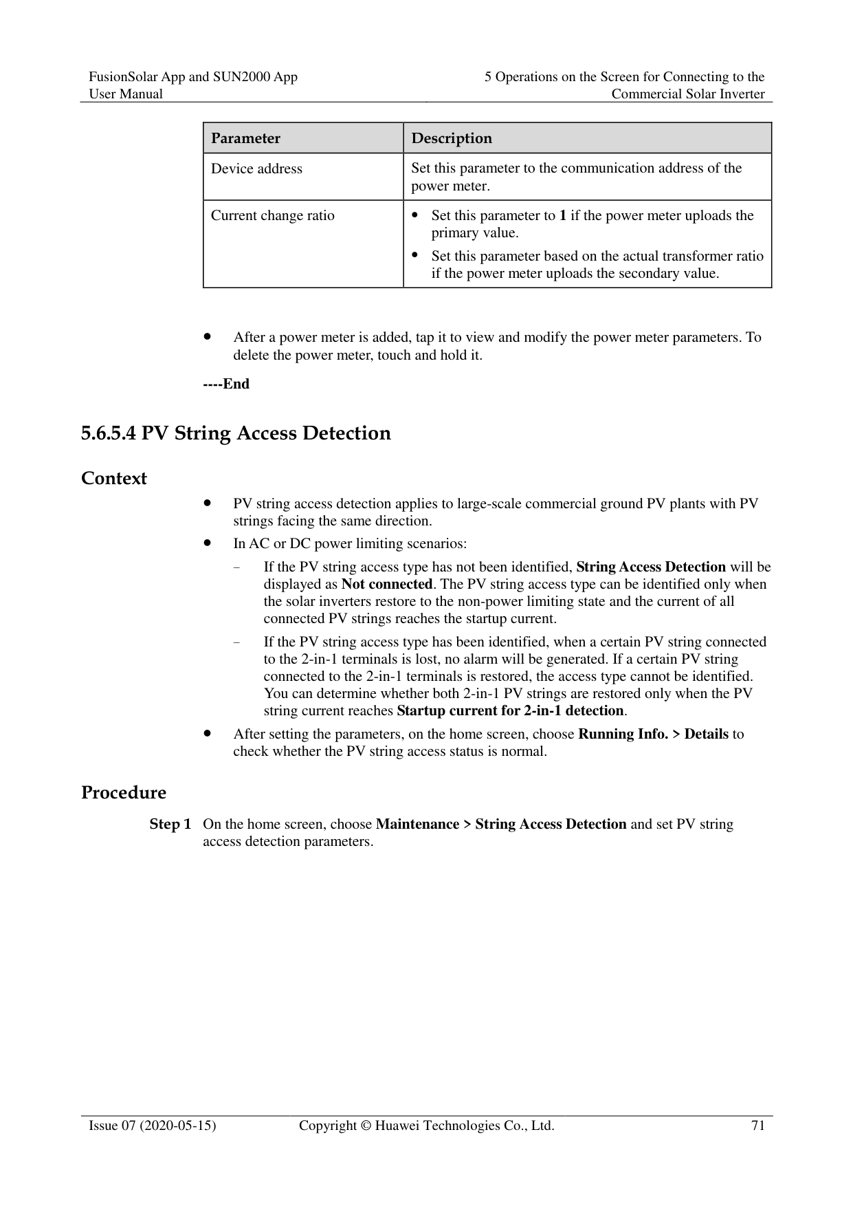
Procedure
----End
####### 5.6.5.10 Clearing Historical Energy Yield Data
Context
If you clear historical energy yield data, all the historical energy yield data of the solar inverters connecting to the app will be cleared.
Procedure
----End
####### 5.6.5.11 Importing and Exporting Configuration Files
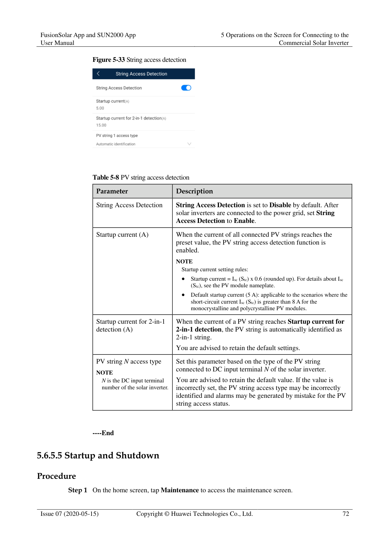
######## Procedure
Tap Export Configuration File to export the configuration files of the solar inverter to the phone.
Tap Import Configuration File to import the configuration files from the phone to the solar inverter.
####### 5.6.5.12 Spot-Check
Context
You can perform spot-check for the solar inverter whose Grid Code is Japan standard. Procedure
Figure 5-34 Spot-Check

----End
####### 5.6.5.13 DC Input Detection
######## Context
The DC input detection function is only applicable to the 1500 V solar inverter system.
########### Step 1 On the home screen, choose Maintenance > Start DC Input Detection to access the DC
input detection screen.
Figure 5-35 Starting DC input detection

Step 2 Tap Start.
----End
####### 5.6.5.14 Device Upgrade
######## Prerequisites
You have obtained the upgrade package with the help of the supplier or Huawei engineers.
In the Android system, you have copied the upgrade package to the mobile phone. The package is a .zip file, which can be saved in a desired path and searched. To reduce the time for searching the package, you are advised to save it in the root directory of the memory or SD card of the mobile phone.
Certain solar inverters (only SUN2000 V500R001C00) support MBUS upgrade. The
actual UI prevails. Procedure
Figure 5-36 Device upgrade

----End
####### 5.6.5.15 Log management
Context
You can tap Log management to export operation logs, as well as alarm records and energy yield information of the solar inverter from the mobile phone.
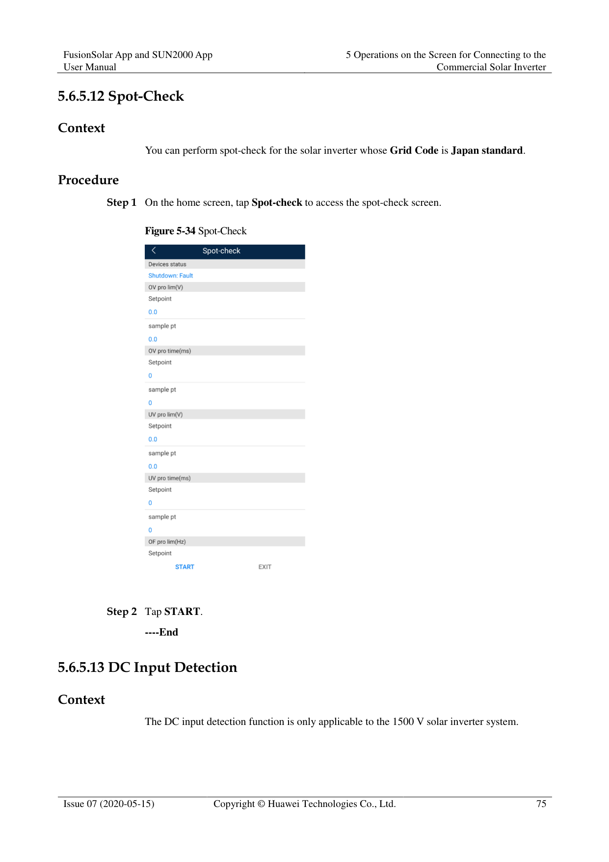
Procedure
Figure 5-37 Downloading logs


By default, Android system logs are saved in the storage/emulated/0/inverterapp folder in the phone memory. You can change the save path by referring to "Setting a File Save Path".
The downloaded solar inverter logs are saved at the Device Log directory in File Management in your mobile phone. You can also send the logs to your mailbox for checking.
----End
####### 5.6.5.16 Changing the WLAN Password
######## Context
You can tap Maintenance on the home screen to change the WLAN password to ensure account security.
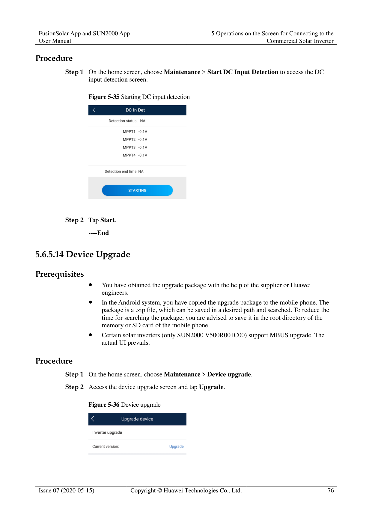

If the communication between the app and the solar inverter has not been established over WLAN, Change WLAN Password is not displayed on the screen.

The password must meet the following requirements:
Contains 8–30 characters.
Contains at least two of the three types: lowercase letters, uppercase letters, and digits.
----End
####### 5.6.5.17 Feedback
######## Context
Users can provide feedback in text, pictures, and files.

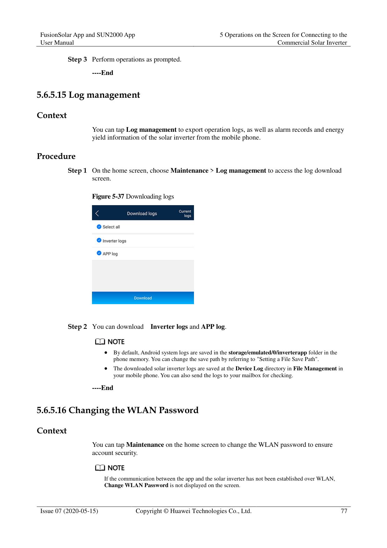
Do not add private data. Procedure

Figure 5-38 Feedback


########### ----End
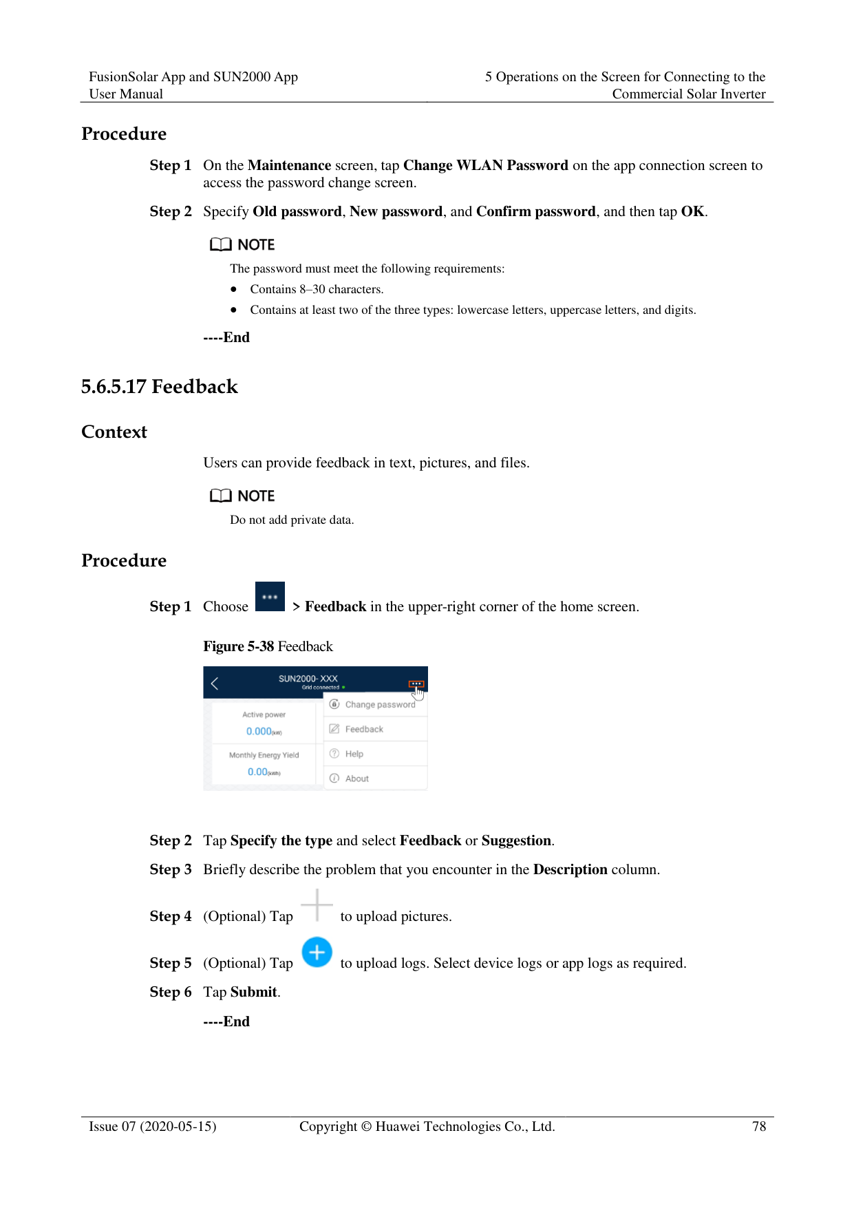
####### 5.6.5.18 Help
Context
If you have any questions when using an involved device or the app, search for solutions in the help information.
Procedure

Figure 5-39 Help

----End
####### 5.6.5.19 About
######## Context
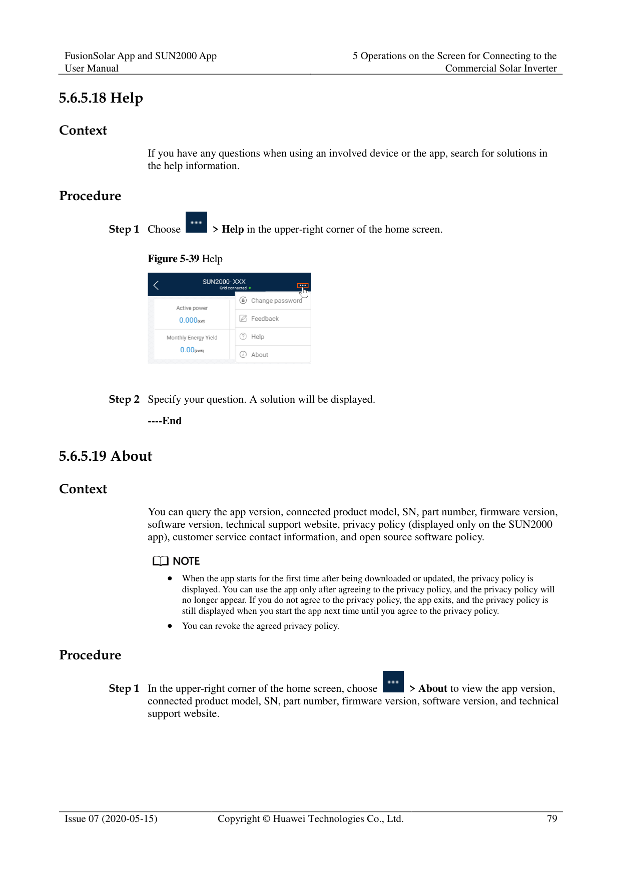
You can query the app version, connected product model, SN, part number, firmware version, software version, technical support website, privacy policy (displayed only on the SUN2000 app), customer service contact information, and open source software policy.

When the app starts for the first time after being downloaded or updated, the privacy policy is displayed. You can use the app only after agreeing to the privacy policy, and the privacy policy will no longer appear. If you do not agree to the privacy policy, the app exits, and the privacy policy is still displayed when you start the app next time until you agree to the privacy policy.
You can revoke the agreed privacy policy. Procedure


----End
#### 5.7 Screen Operations (Special User)
##### 5.7.1 QueryProcedure
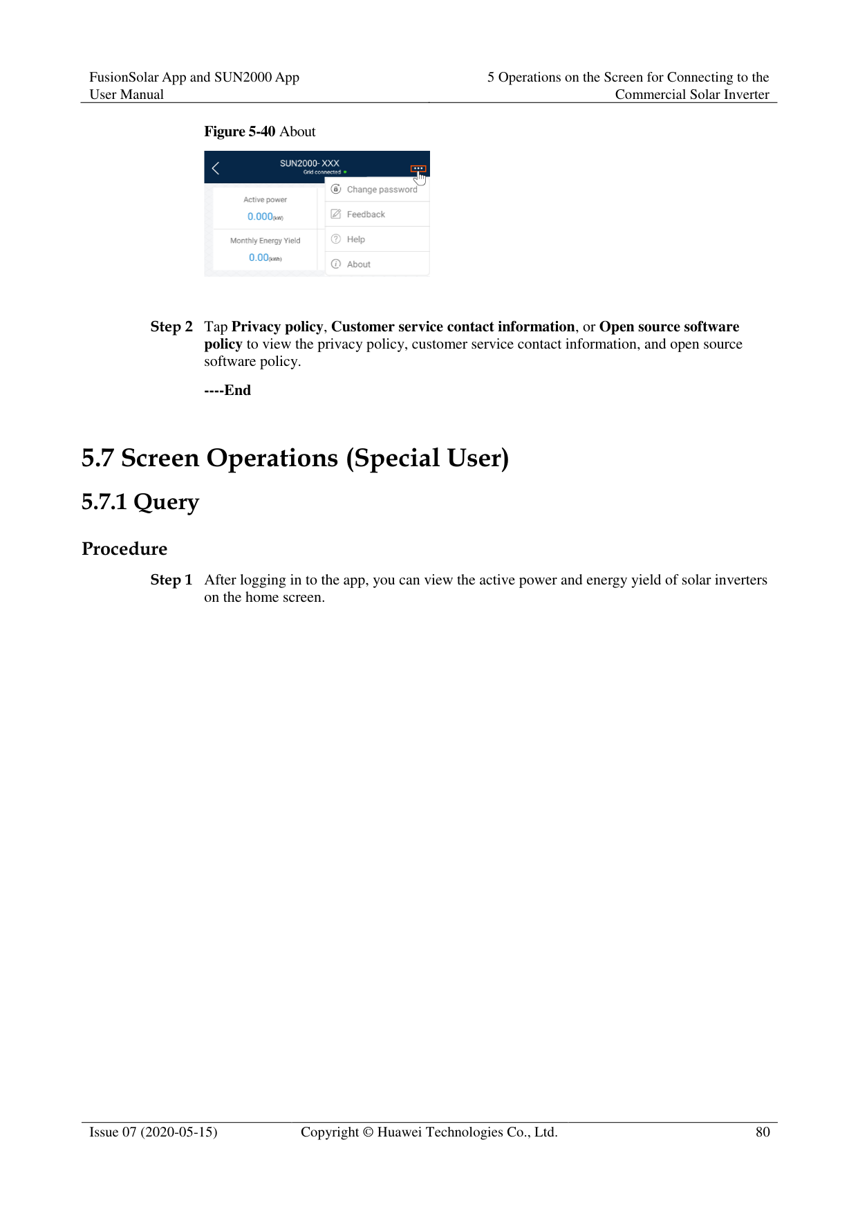

Tap an alarm record and view the alarm details.
Swipe right or left on the screen or tap either Active Alarm or Historical Alarm to display a list of active alarms or historical alarms.

Tap Sort by generated time to set the alarm sorting mode for active alarms or historical alarms.

Tap to set a time criterion. The historical alarms generated within the time segment are displayed.
Select the alarms that can be manually cleared, and tap Delete on the right of the alarm to manually clear the alarms.


Alarms that have been manually cleared can be viewed on the Historical Alarm screen.
Only the AFCI Self-Check Failure and DC Arc Fault alarms can be manually cleared. Only the products whose technical specifications contain AFCI supports manual alarm clearance.
########### ----End
##### 5.7.2 Settings
On the home screen, a special user can tap Settings to set power grid, protection, and feature parameters for the solar inverter.
Figure 5-42 Settings (special user)


The configurable solar inverter parameters vary with the solar inverter model and grid code. The displayed parameters prevail. The parameter list provided in this section includes all configurable parameters.
The parameter ranges vary with the device model. The listed ranges are for reference only.
The parameter names, value ranges, and default values are subject to change. The actual display prevails.
####### 5.7.2.1 Setting Grid Parameters
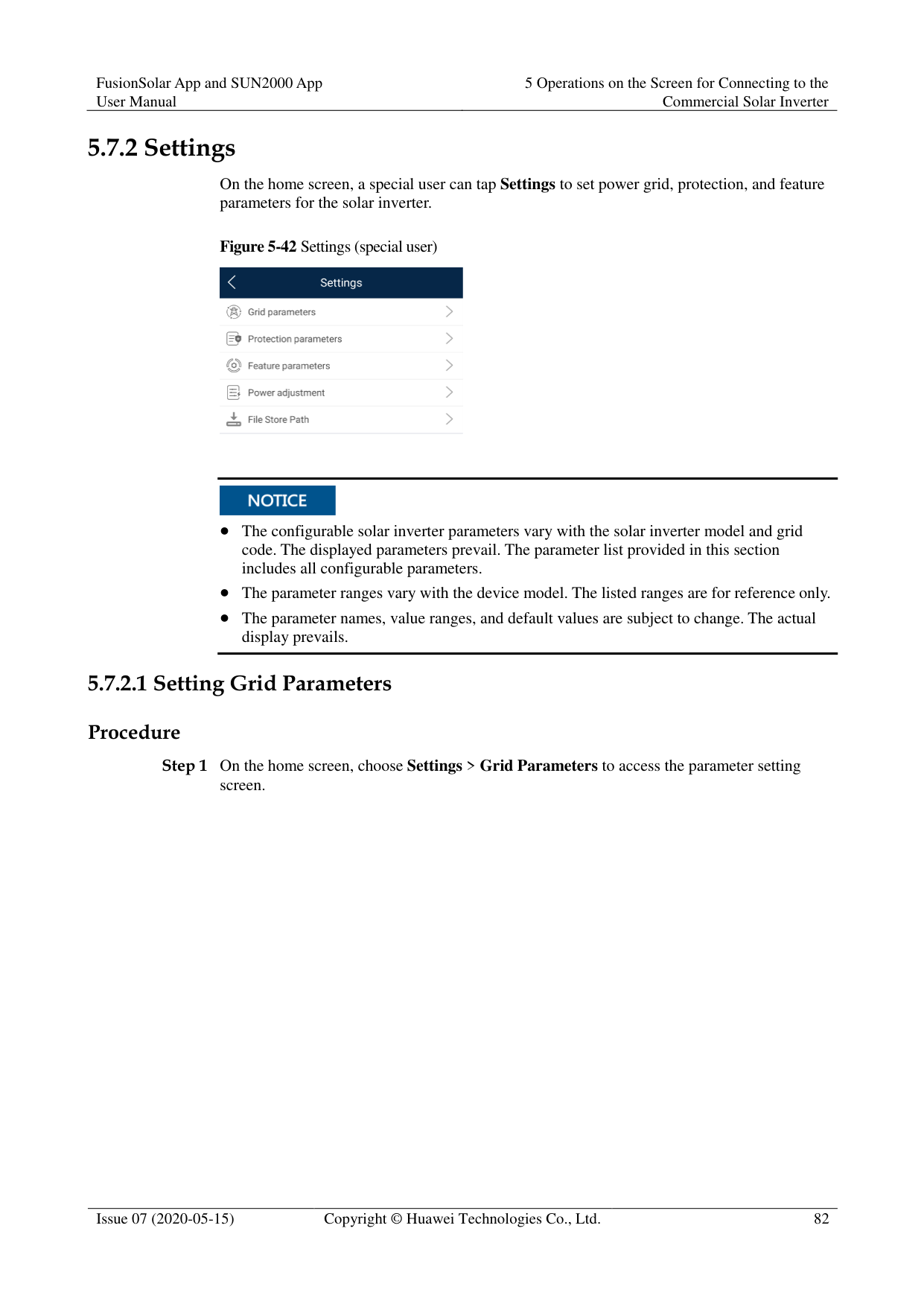
######## Procedure
Step 1 On the home screen, choose Settings > Grid Parameters to access the parameter setting
screen.
Figure 5-43 Grid parameters (special user)

For details about how to set the parameters, see A Commercial Smart Inverters Parameters.
----End
####### 5.7.2.2 Setting Protection Parameters
######## Procedure
Step 1 On the home screen, choose Settings > Protection Parameters to access the parameter
setting screen.
Figure 5-44 Protection parameters (special user)

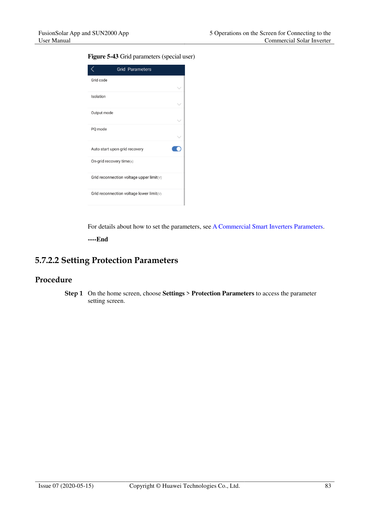
For details about how to set the parameters, see A Commercial Smart Inverters Parameters.
----End
####### 5.7.2.3 Setting Feature Parameters
######## Procedure
Step 1 On the home screen, choose Settings > Feature Parameters to access the parameter setting
screen.
Figure 5-45 Feature parameters (special user)

For details about how to set the parameters, see A Commercial Smart Inverters Parameters.
----End
####### 5.7.2.4 Setting Power Adjustment Parameters
Procedure
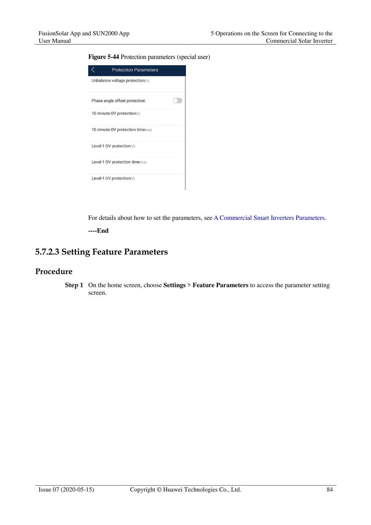
Step 1 On the home screen, choose Settings > Power Adjustment to access the parameter setting
screen.
Figure 5-46 Power adjustment parameters (special user)

For details about how to set the parameters, see A Commercial Smart Inverters Parameters.
----End
####### 5.7.2.5 Setting a File Save Path
######## Prerequisite
This function is available only on the Android system.
######## Context
You can modify the save path for operation logs and solar inverter logs and export logs from the path.
######## Procedure
Step 1 On the home screen, choose Settings > File Save Path to access the path setting screen.
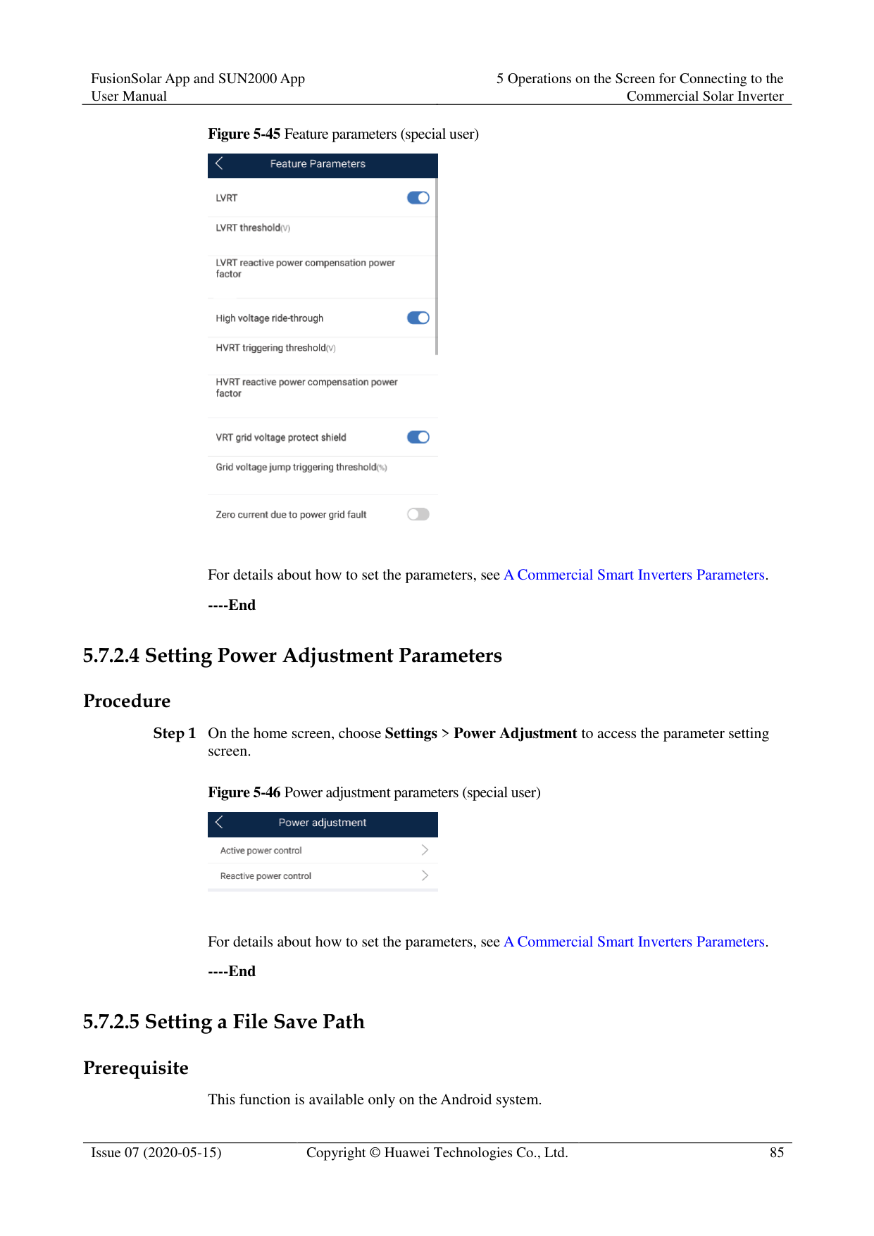
Figure 5-47 File save path

Step 2 Tap File save path to set a file save path.
----End
##### 5.7.3 Power Adjustment
######## Context
Due to permission restrictions, special users support the setting of power adjustment, which can set the active power, reactive power, and grid connection point control parameters of the solar inverter.
######## Procedure
########### Step 1 On the home screen, tap Power Adjustment.
Figure 5-48 Power adjustment

############ Step 2 Set power parameters as required.For details about how to set the parameters, see A Commercial Smart Inverters Parameters.
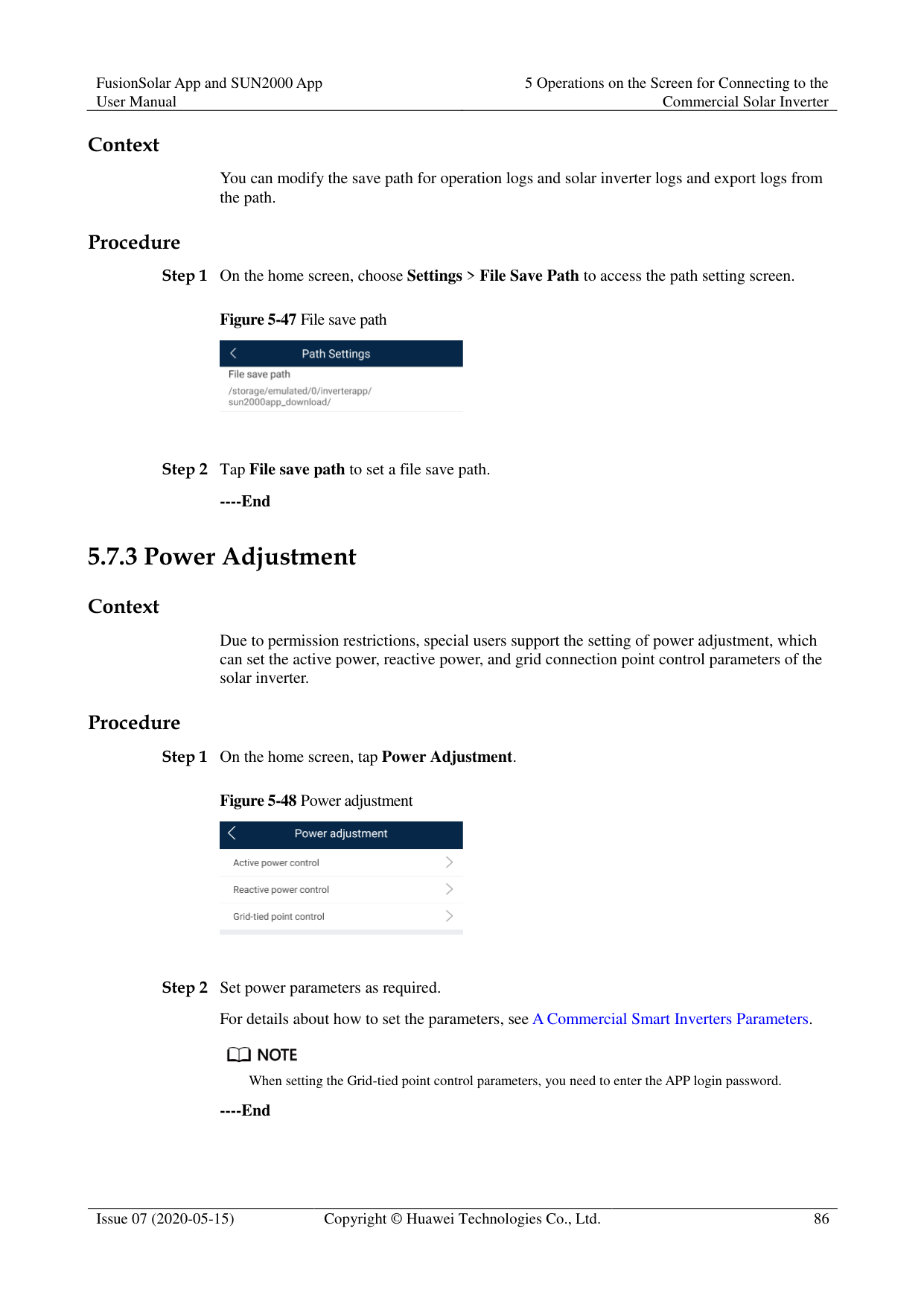

When setting the Grid-tied point control parameters, you need to enter the APP login password.
########### ----End
##### 5.7.4 Maintenance
On the home screen, a special user can tap Maintenance to start or shut down the solar inverter and restore factory settings.
Figure 5-49 Maintenance (special user)

####### 5.7.4.1 Add/Delete Device
########### Step 1 On the home screen, choose Maintenance > Device Mgmt to access the Add/Delete device
screen.
Figure 5-50 Add/Delete device

Tap + to add a power meter.
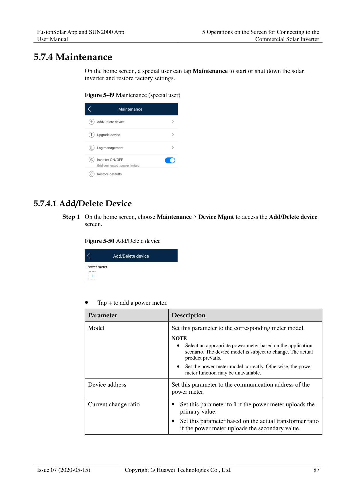
|Parameter|Description| |---|---| |Model|Set this parameter to the corresponding meter model. NOTE
Select an appropriate power meter based on the application scenario. The device model is subject to change. The actual product prevails.
Set the power meter model correctly. Otherwise, the power meter function may be unavailable.| |Device address|Set this parameter to the communication address of the power meter.| |Current change ratio| Set this parameter to 1 if the power meter uploads the primary value.
Set this parameter based on the actual transformer ratio if the power meter uploads the secondary value.|
After a power meter is added, tap it to view and modify the power meter parameters. To delete the power meter, touch and hold it.
----End
####### 5.7.4.2 Startup and ShutdownProcedure

----End
####### 5.7.4.3 Restoring Factory SettingsContext
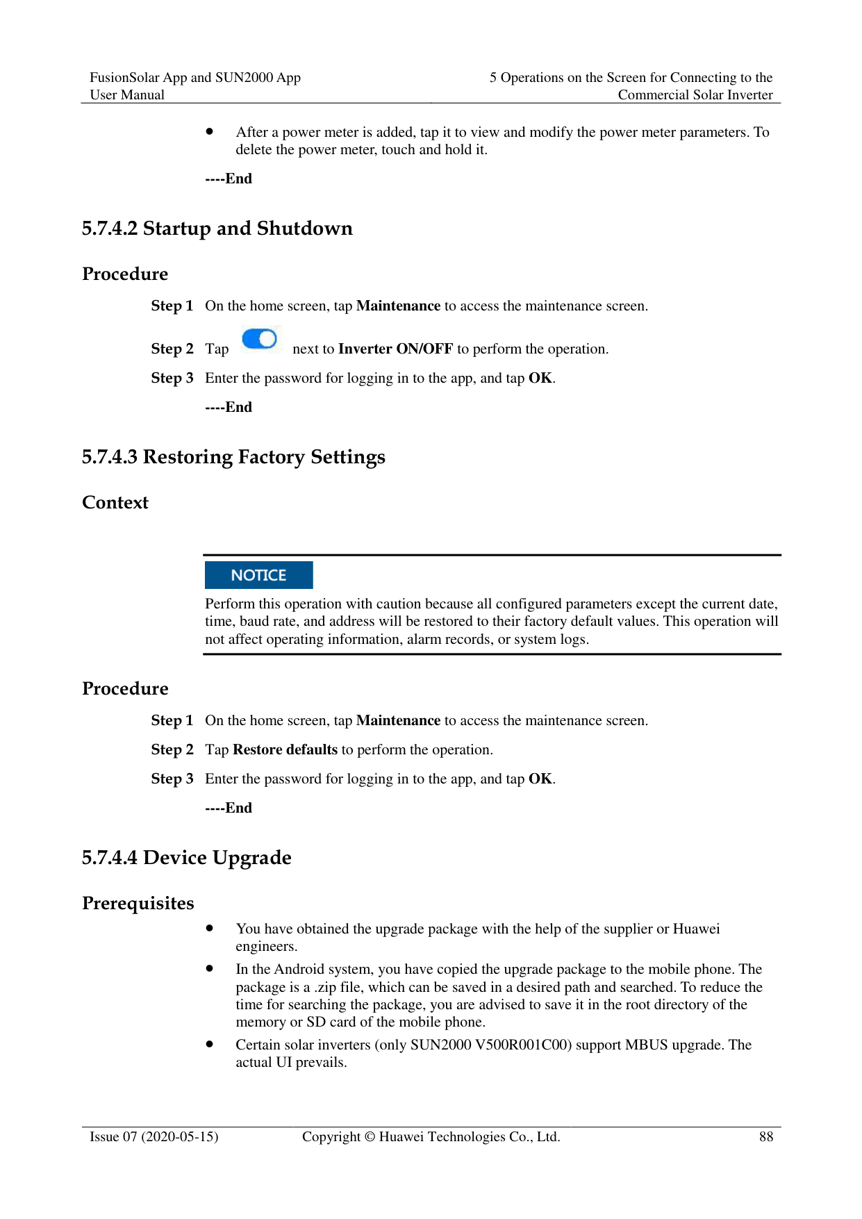

Perform this operation with caution because all configured parameters except the current date, time, baud rate, and address will be restored to their factory default values. This operation will not affect operating information, alarm records, or system logs.
Procedure
----End
####### 5.7.4.4 Device Upgrade
######## Prerequisites
You have obtained the upgrade package with the help of the supplier or Huawei engineers.
In the Android system, you have copied the upgrade package to the mobile phone. The package is a .zip file, which can be saved in a desired path and searched. To reduce the time for searching the package, you are advised to save it in the root directory of the memory or SD card of the mobile phone.
Certain solar inverters (only SUN2000 V500R001C00) support MBUS upgrade. The actual UI prevails.
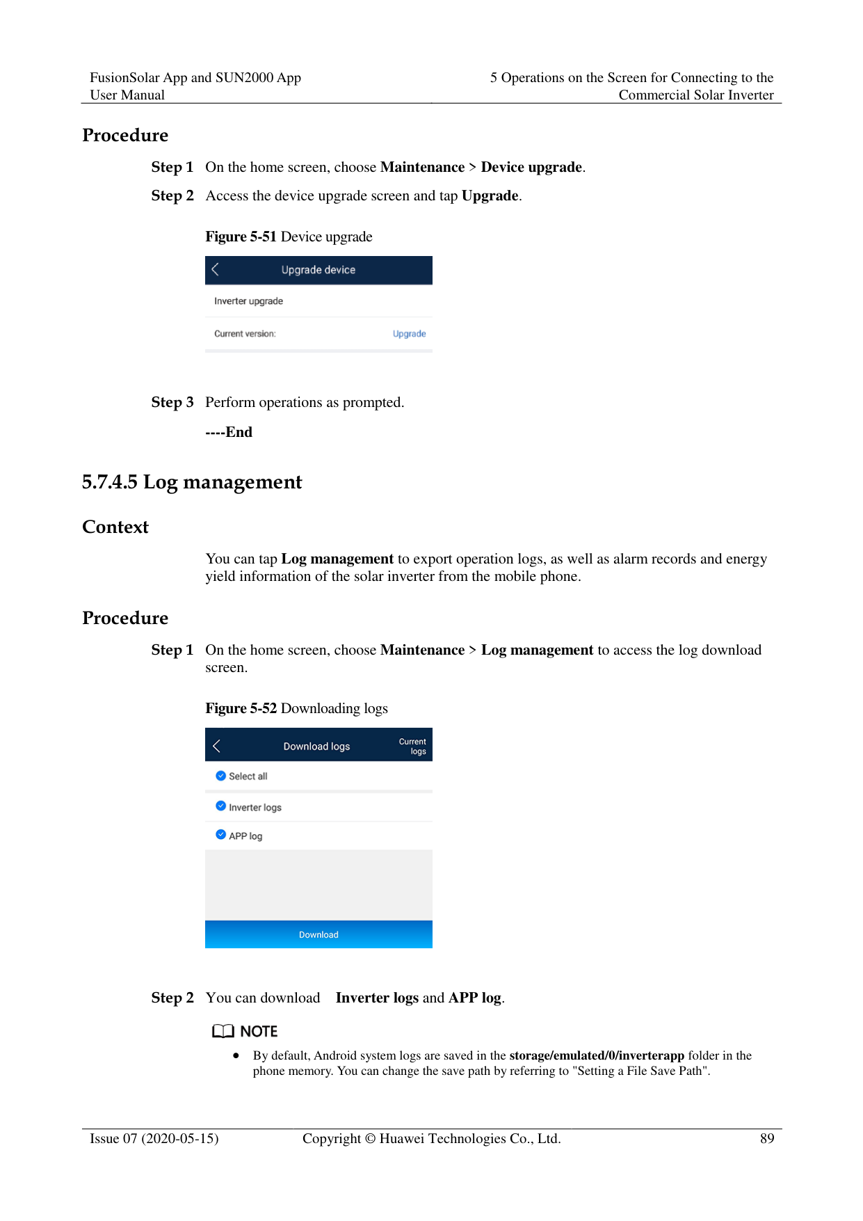
Figure 5-51 Device upgrade

----End
####### 5.7.4.5 Log management
######## Context
You can tap Log management to export operation logs, as well as alarm records and energy yield information of the solar inverter from the mobile phone.
######## Procedure
Figure 5-52 Downloading logs

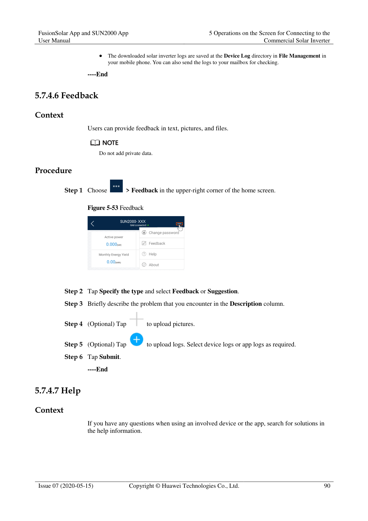

By default, Android system logs are saved in the storage/emulated/0/inverterapp folder in the phone memory. You can change the save path by referring to "Setting a File Save Path".
The downloaded solar inverter logs are saved at the Device Log directory in File Management in your mobile phone. You can also send the logs to your mailbox for checking.
----End
####### 5.7.4.6 Feedback
Context
Users can provide feedback in text, pictures, and files.

Do not add private data. Procedure

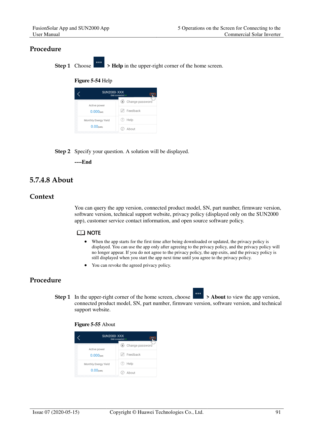
Figure 5-53 Feedback


----End
####### 5.7.4.7 Help
######## Context
If you have any questions when using an involved device or the app, search for solutions in the help information.
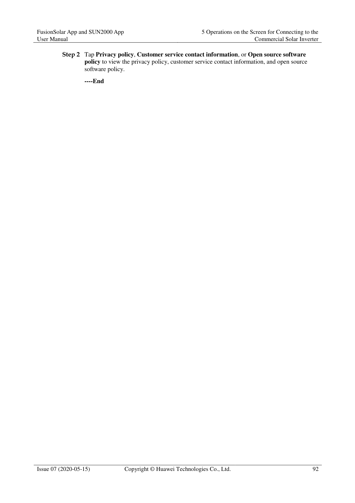

Step 1 Choose > Help in the upper-right corner of the home screen.
########### Figure 5-54 Help

Step 2 Specify your question. A solution will be displayed.
----End
####### 5.7.4.8 About
######## Context
You can query the app version, connected product model, SN, part number, firmware version, software version, technical support website, privacy policy (displayed only on the SUN2000 app), customer service contact information, and open source software policy.

When the app starts for the first time after being downloaded or updated, the privacy policy is displayed. You can use the app only after agreeing to the privacy policy, and the privacy policy will no longer appear. If you do not agree to the privacy policy, the app exits, and the privacy policy is still displayed when you start the app next time until you agree to the privacy policy.
You can revoke the agreed privacy policy. Procedure

########### Figure 5-55 About

########### ----End
6 Operations on the Screen for Connecting
to the SmartLogger

The app screenshots provided in this section correspond to the SUN2000 app 3.2.00.005 version. The data on the screenshots is for reference only.
Delivering a reset, factory reset, shutdown, or upgrade command to the solar inverters may cause power grid connection failure, which affects the energy yield.
Only professionals are allowed to set the grid parameters, protection parameters, feature parameters, power adjustment parameters, and grid-tied point control parameters of the solar inverters. If the grid parameters, protection parameters, and feature parameters are incorrectly set, the solar inverters may not connect to the power grid. If the power adjustment parameters and grid-tied point control parameters are incorrectly set, the solar inverters may not connect to the power grid as required. In these cases, the energy yield will be affected.
Only professionals are allowed to set the power grid scheduling parameters of the SmartLogger. Incorrect settings may cause the PV plant to fail to connect to the power grid as required, which affects the energy yield.
#### 6.1 SmartLogger
######## Connection Modes
The SmartLogger2000 has a built-in Bluetooth module. The app can be connected to the SmartLogger2000 over Bluetooth after the SmartLogger2000 is powered on.
The SmartLogger1000A/SmartLogger3000 has a built-in WLAN module. The app can be connected to the SmartLogger1000A/SmartLogger3000 over WLAN after the SmartLogger1000A/SmartLogger3000 is powered on.
|SmartLogger|SmartLogger Version
|App Version|Bluetooth Connection
|WLAN Connection
| |---|---|---|---|---| |SmartLogger3000|SmartLogger V300R001C00 and later versions|3.2.00.005|-|Supported| |SmartLogger2000|SmartLogger V200R001C00SP C103 and later versions|3.2.00.005|Supported
|-| |SmartLogger2000|SmartLogger V200R001C10SP C010 and later versions|3.2.00.005|Supported
|-| |SmartLogger2000|SmartLogger V200R001C30 and later versions|3.2.00.005|Supported
|-| |SmartLogger2000|SmartLogger V200R002C10 and later versions|3.2.00.005|Supported
|-| |SmartLogger2000|SmartLogger V200R002C20 and later versions|3.2.00.005|Supported
|-| |SmartLogger1000A|SmartLogger V100R002C00 and later versions|3.2.00.005|-|Supported|
#### 6.2 User Operation Permissions
For SmartLogger2000 and SmartLogger1000A, the user accounts that can log in to the app are classified into common users, special users, and advanced users. You can set different user permissions based on the responsibilities of PV plant operation personnel.
Common users: Has the permissions of viewing data about the SmartLogger and the devices connected to it, setting SmartLogger user parameters, and changing the system password.
Advanced users: Has the permissions of viewing data about the SmartLogger and the devices connected to it, setting functional parameters, managing devices, and maintaining the system.
Special users: Has the permissions of viewing data about the SmartLogger and the devices connected to it, managing devices, and maintaining the system.
For SmartLogger3000, the user accounts that can log in to the app are classified into installer and user, user permissions can refer to common users permissions, and installer permissions can refer to advanced users permissions and special users permissions.
Figure 6-1, Figure 6-2, and Figure 6-3 show the menu operation permissions of common users, special users, and advanced users respectively.


Common users can view data and start or shut down the devices under Monitoring.


Advanced users can view data, set parameters, download logs, and start or shut down the devices under Monitoring.
Path Settings is available only to the Android system.


Special users can view data, download logs, and start or shut down the devices under Monitoring.
#### 6.3 Login
######## Prerequisites
The SmartLogger has been powered on.
The Bluetooth function of the SmartLogger is enabled by default.
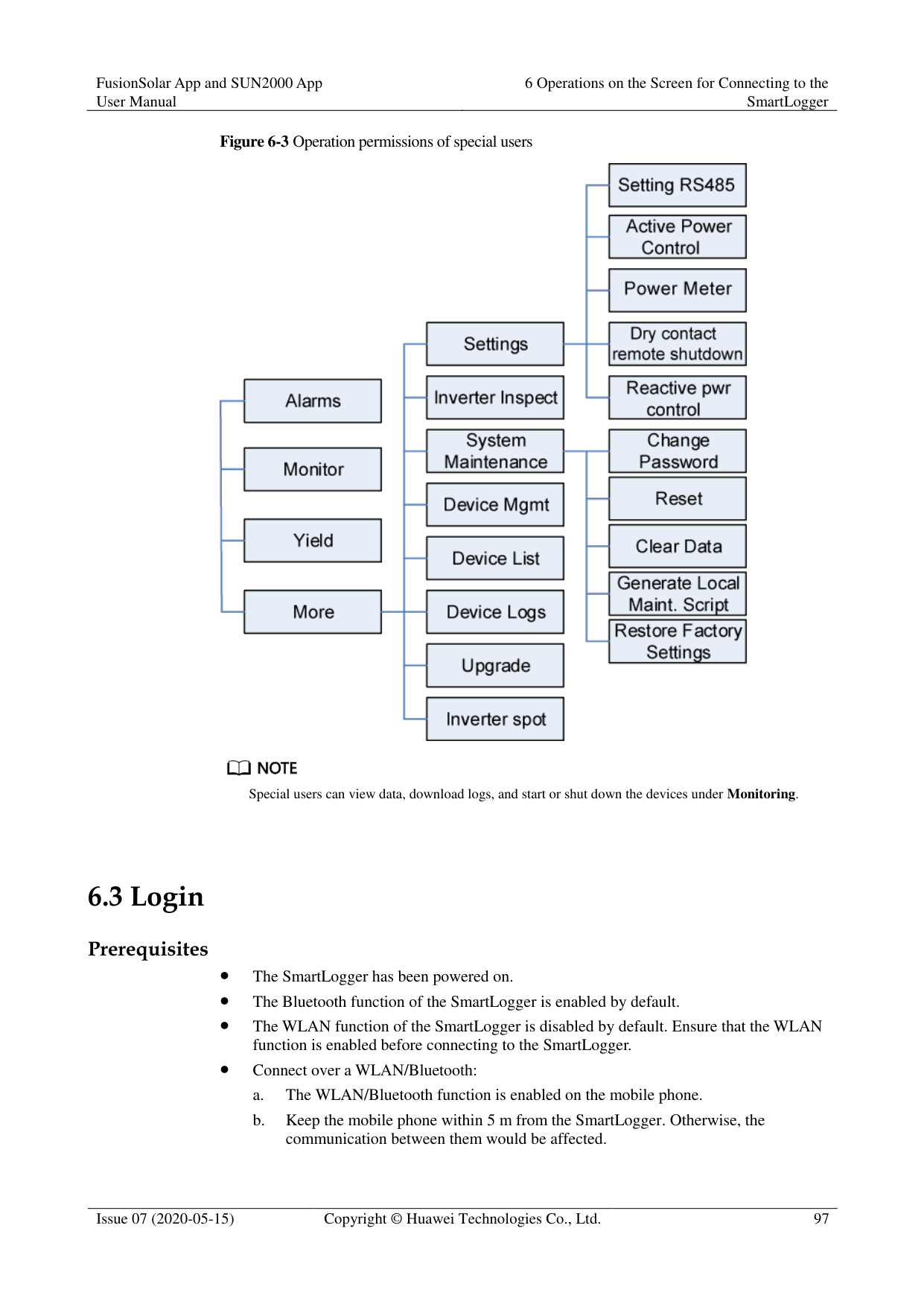
The WLAN function of the SmartLogger is disabled by default. Ensure that the WLAN function is enabled before connecting to the SmartLogger.
Connect over a WLAN/Bluetooth:
######## Procedure
########### Figure 6-4 Connect

Code scanning: On the scanning screen, place the QR code of the Device in the scan frame. The device will be automatically connected after the code is identified.
########### Figure 6-5 Scan

Manual connection: On the scanning screen, tap Manual Connection and select a connection mode.
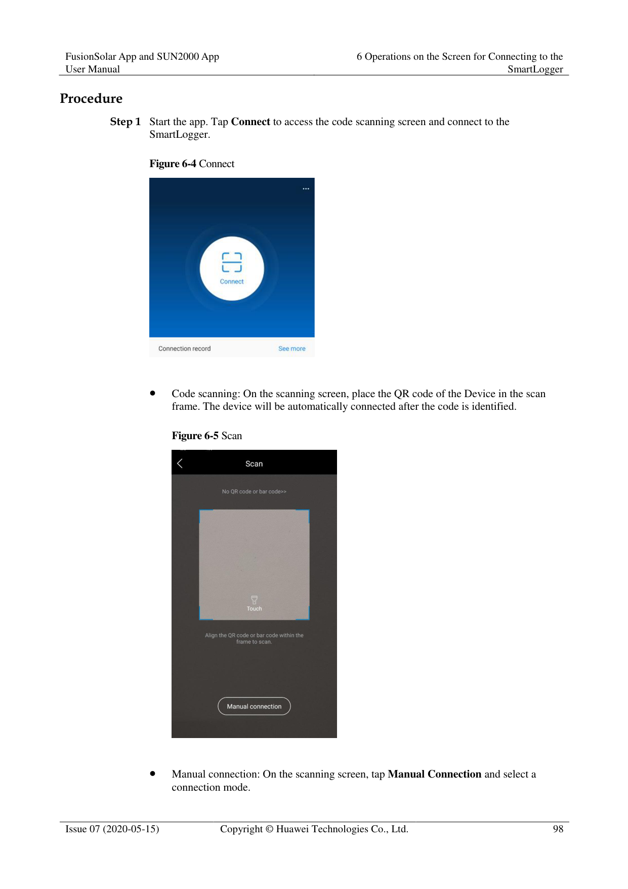
Figure 6-6 Manual connection

Select WLAN and connect the SmartLogger1000A or SmartLogger3000 to the corresponding WLAN in the WLAN connection list of the APP. The initial name of the WLAN is Logger_SN bar code, and the initial password is Changeme.

Use the initial password upon first power-on and change it immediately after login. To ensure account security, change the password periodically and keep the new password in mind. Not changing the initial password may cause password disclosure. A password left unchanged for a long period of time may be stolen or cracked. If a password is lost, devices cannot be accessed. In these cases, the user is liable for any loss caused to the PV plant.
− Select Bluetooth, and tap Search for Device. After a Bluetooth device is found, select the target Bluetooth device, and set up a connection. When the Bluetooth connection is used for the SmartLogger2000, the name of the connected Bluetooth device is LOG+last eight digits of the SN bar code.
########### Figure 6-7 Login


The login password is the same as that for the SmartLogger connected to the app and is used only when the SmartLogger connects to the app.
For SmartLogger1000A and SmartLogger2000, the initial passwords for Common User,
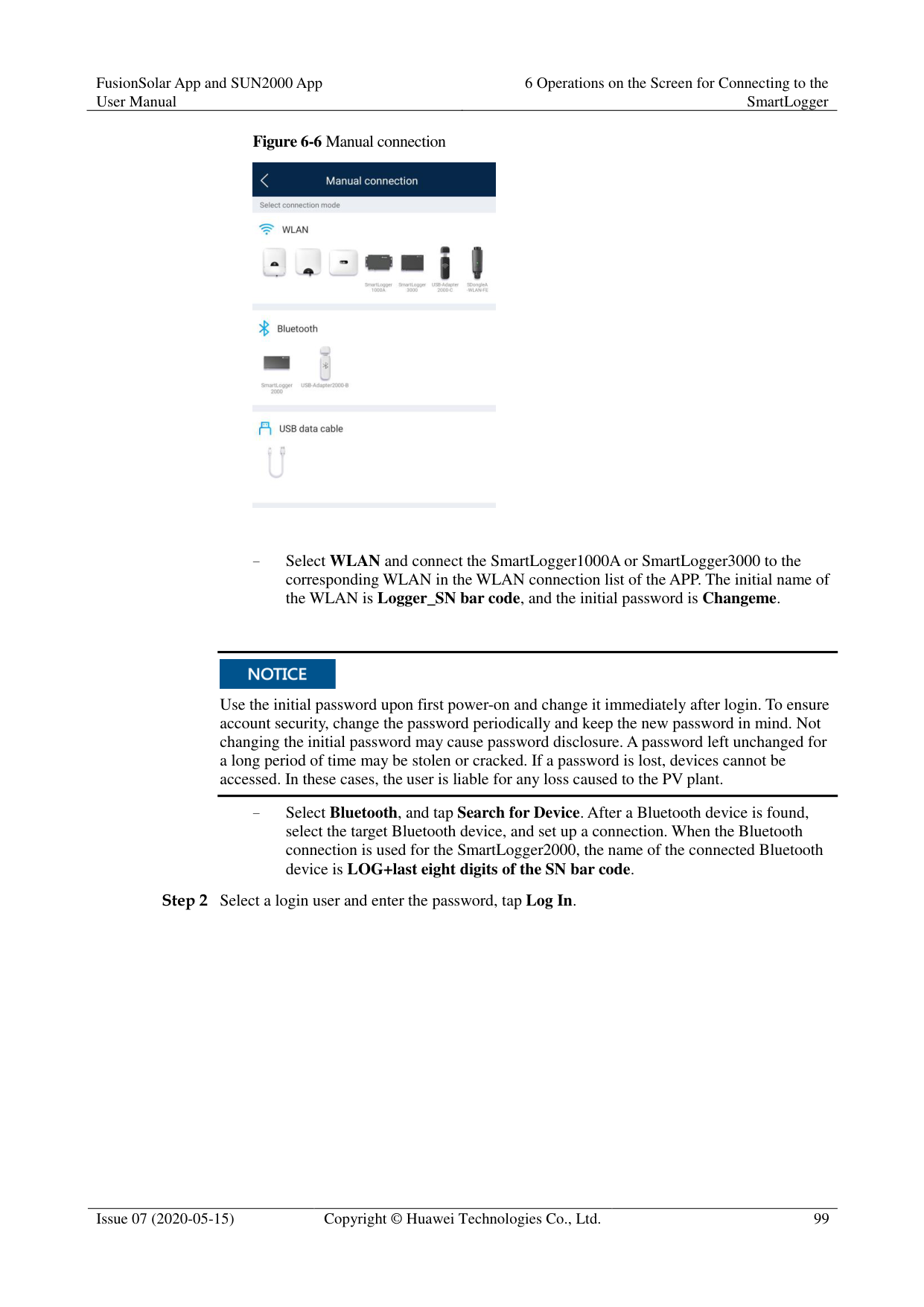
########### Advanced User, and Special User are all 00000a.
For SmartLogger3000, the initial passwords for installer and user are all 00000a.
Use the initial password upon first power-on and change it immediately after login. To ensure account security, change the password periodically and keep the new password in mind. Not changing the initial password may cause password disclosure. A password left unchanged for a long period of time may be stolen or cracked. If a password is lost, devices cannot be accessed. In these cases, the user is liable for any loss caused to the PV plant.
During the login, if five consecutive invalid password entries are made (the interval between two consecutive entries is less than 2 minutes), the account will be locked for 10 minutes. The password should consist of six characters.

If you log in to the app after the SmartLogger powers on for the first time or the SmartLogger factory defaults are restored, the quick settings screen will be displayed. You can set basic parameters for the SmartLogger on the Quick Settings screen. After the setting, you can modify the parameters after choosing MoreSettings.
If you do not set basic parameters for the SmartLogger on the Quick Settings screen, the screen is still displayed when you log in to the app next time.
----End
#### 6.4 Screen Operations (Common User)
##### 6.4.1 Query
######## Procedure
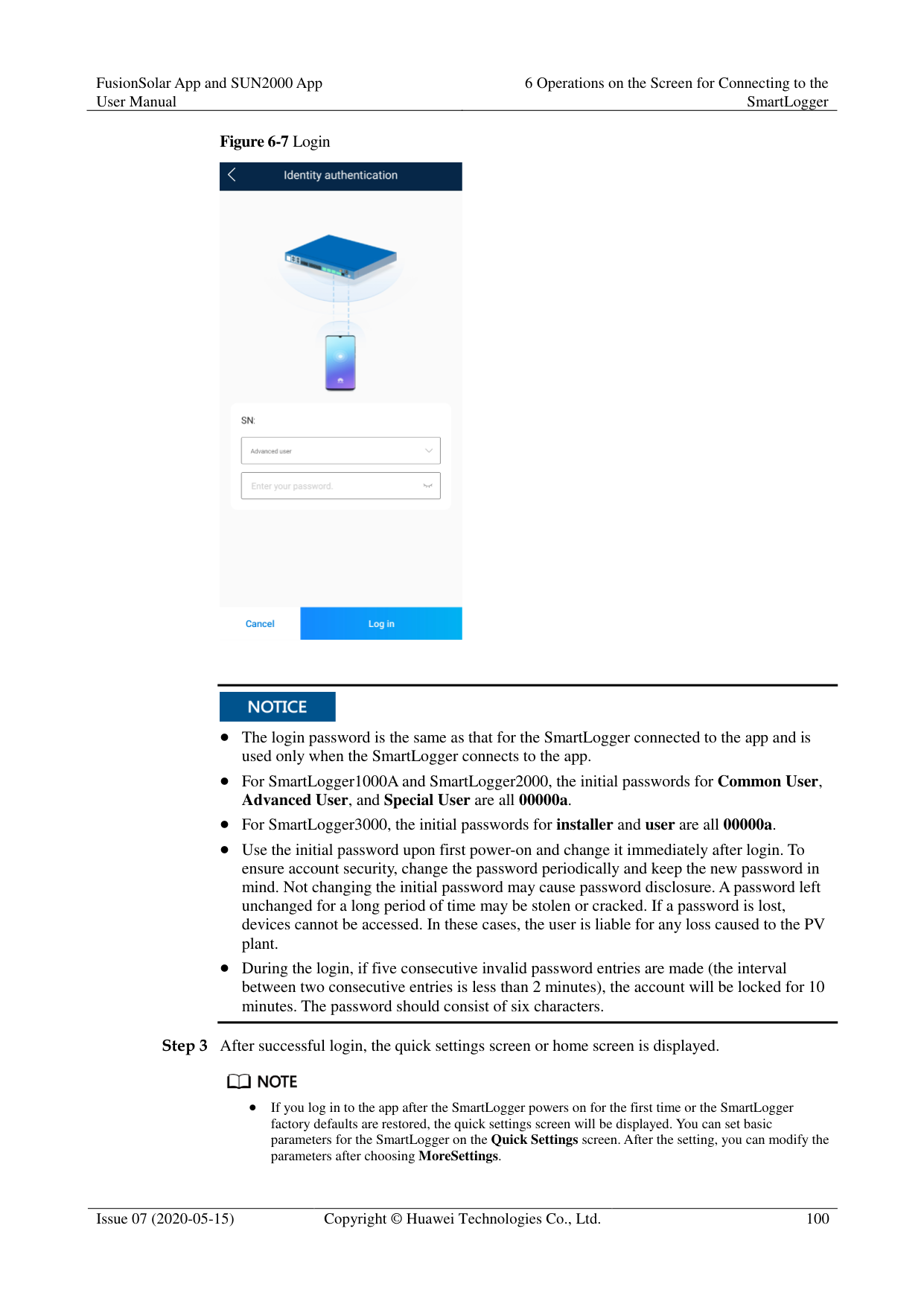
Step 1 After logging in to the app, you can view the running details of the connected solar inverters
on the home screen.
Figure 6-8 Home screen

Table 6-2 Home screen
|Parameter|Description| |---|---| |Total Inverter Qty|Number of solar inverters connected to the SmartLogger.| |Rated power|Total rated power of solar inverters connected to the SmartLogger.|
|Parameter|Description| |---|---| |Output power|Total output power of solar inverters connected to the SmartLogger.| |E-Total|Total energy yields of solar inverters connected to the SmartLogger.| |E-Daily|Total energy yields of solar inverters connected to the SmartLogger on the current day.| |CO2 reduction|Total amount of reduced CO2 emission of the solar inverters connected to the SmartLogger| |Income|Total revenues corresponding to energy yields of solar inverters connected to the SmartLogger.| |Grid scheduling|Active power percentage and reactive power factor for power grid scheduling.| |Alarm|Current alarms: You can view the detailed information about major, minor, and warning alarms.
Historical alarms: You can view details about historical alarms filtered by sequence number, device, and time.|
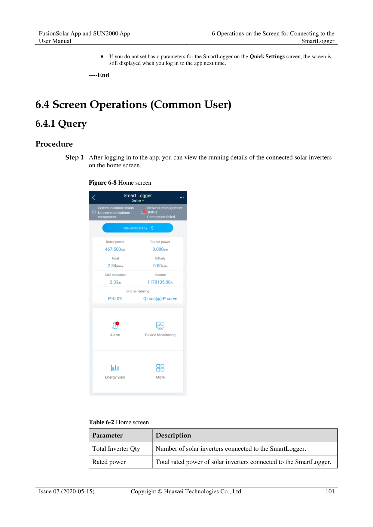
|Yield|You can query information about energy yields of all solar inverters connected to the SmartLogger.
Tap Day, Month, Year, or History to display the daily, monthly, yearly, or historical energy yield information.|
----End
##### 6.4.2 Settings
A common user can choose More > Settings to set user parameters for the SmartLogger.
Figure 6-9 Settings (Common User)

####### 6.4.2.1 Setting the System Date and TimeProcedure
Figure 6-10 Date&Time screen


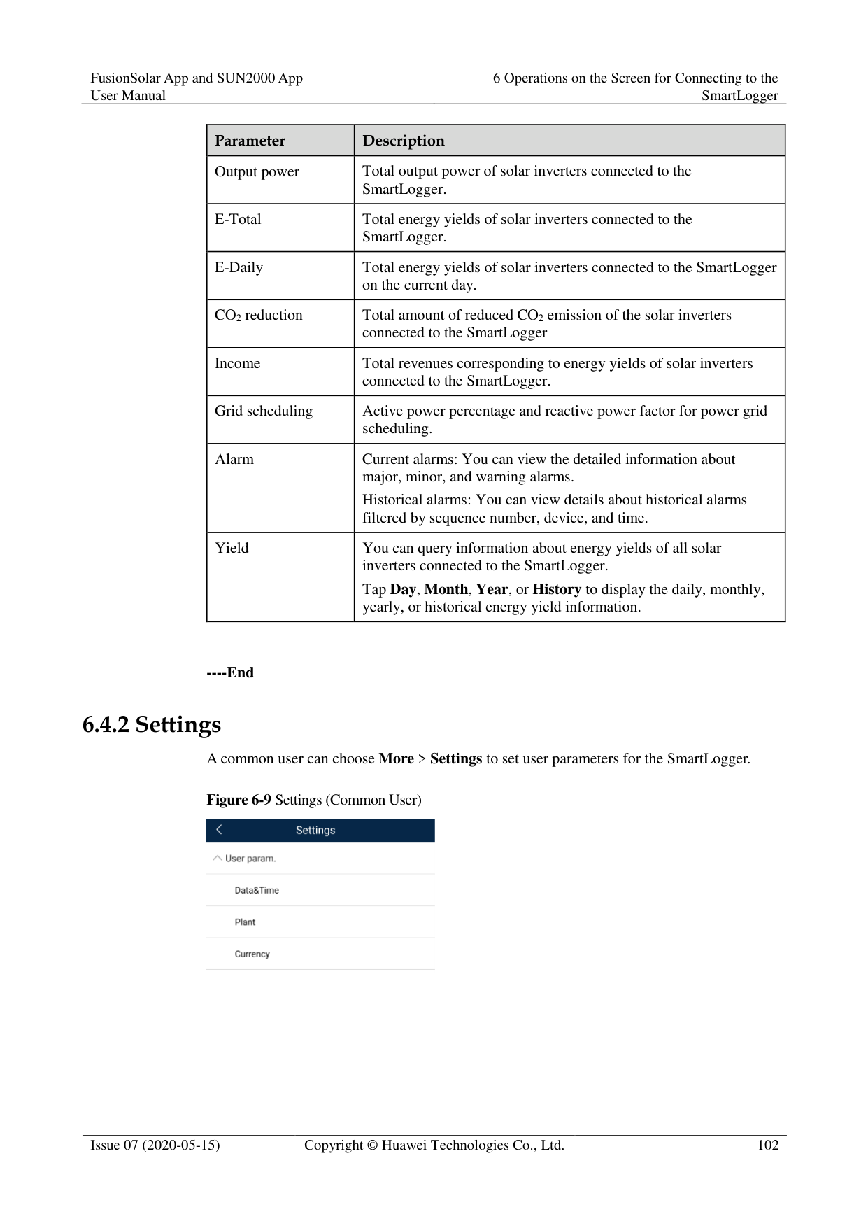
For a solar inverter that supports DST, if an advanced user enables DST, a common user can view DST data. The displayed parameters are for reference only.
----End
####### 6.4.2.2 Setting Plant InformationStep 1 Choose More > Settings > User param. > Plant to access the parameter setting screen.
########### Figure 6-11 Plant

Step 2 Tap target parameters. On the displayed screen, enter or select relevant information.

The plant parameters that are manually entered must not contain any special character, such as <>:,`'?()#&\$|%+;~^" in the English half-width status.
----End
####### 6.4.2.3 Setting Revenue Parameters
######## Procedure
Step 1 Choose More > Settings > User param. > Currency to access the parameter setting screen.
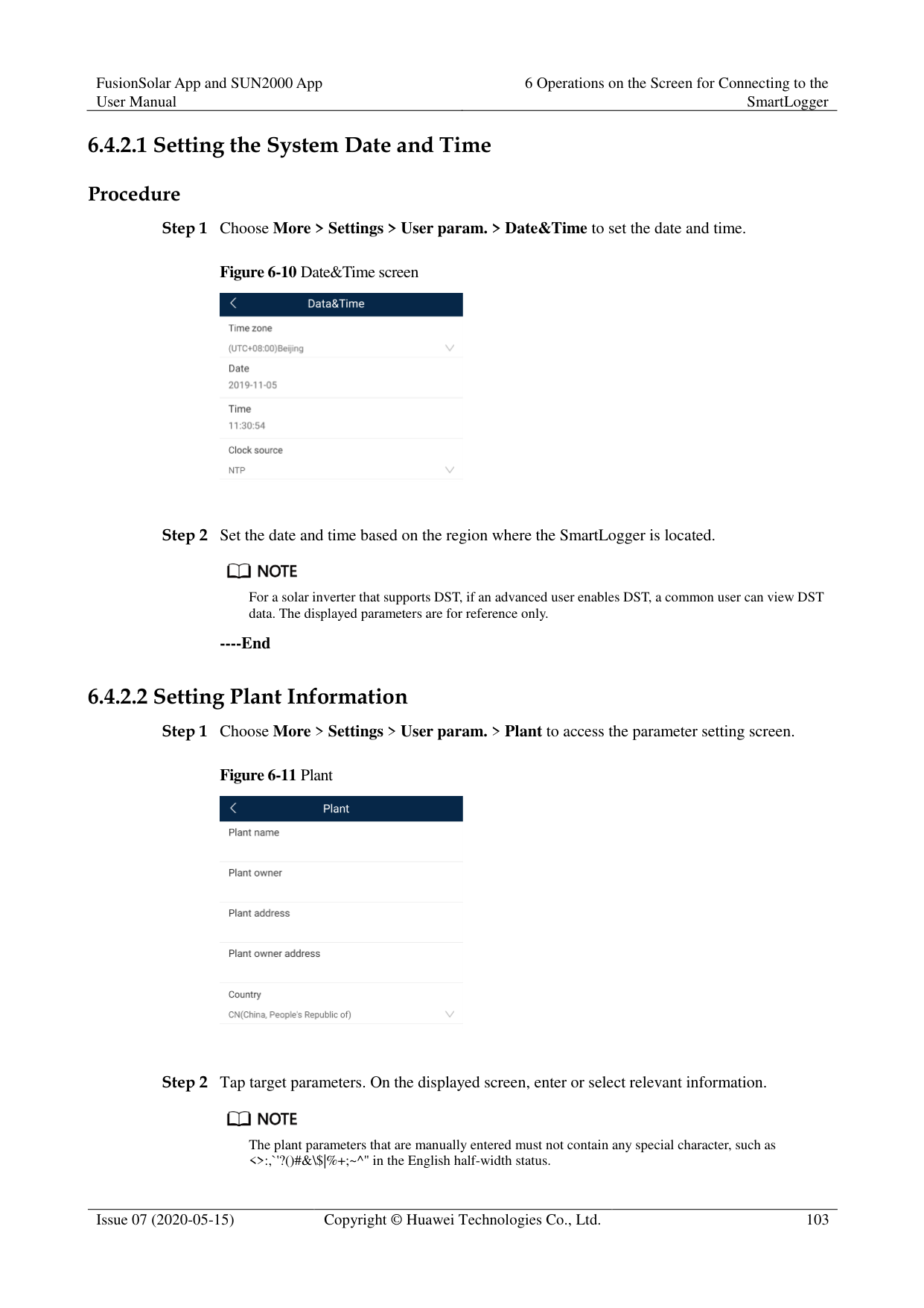
Figure 6-12 Gain

----End
##### 6.4.3 Maintenance
####### 6.4.3.1 System Maintenance
######## Context
A common user can choose More > System Maintenance to change only the SmartLogger password.
######## Procedure
########### Step 1 Choose More > System Maintenance > Change Password to access the password change
screen.
Figure 6-13 Changing a password

Step 2 Type the old password, new password, and confirmation password. Tap OK.
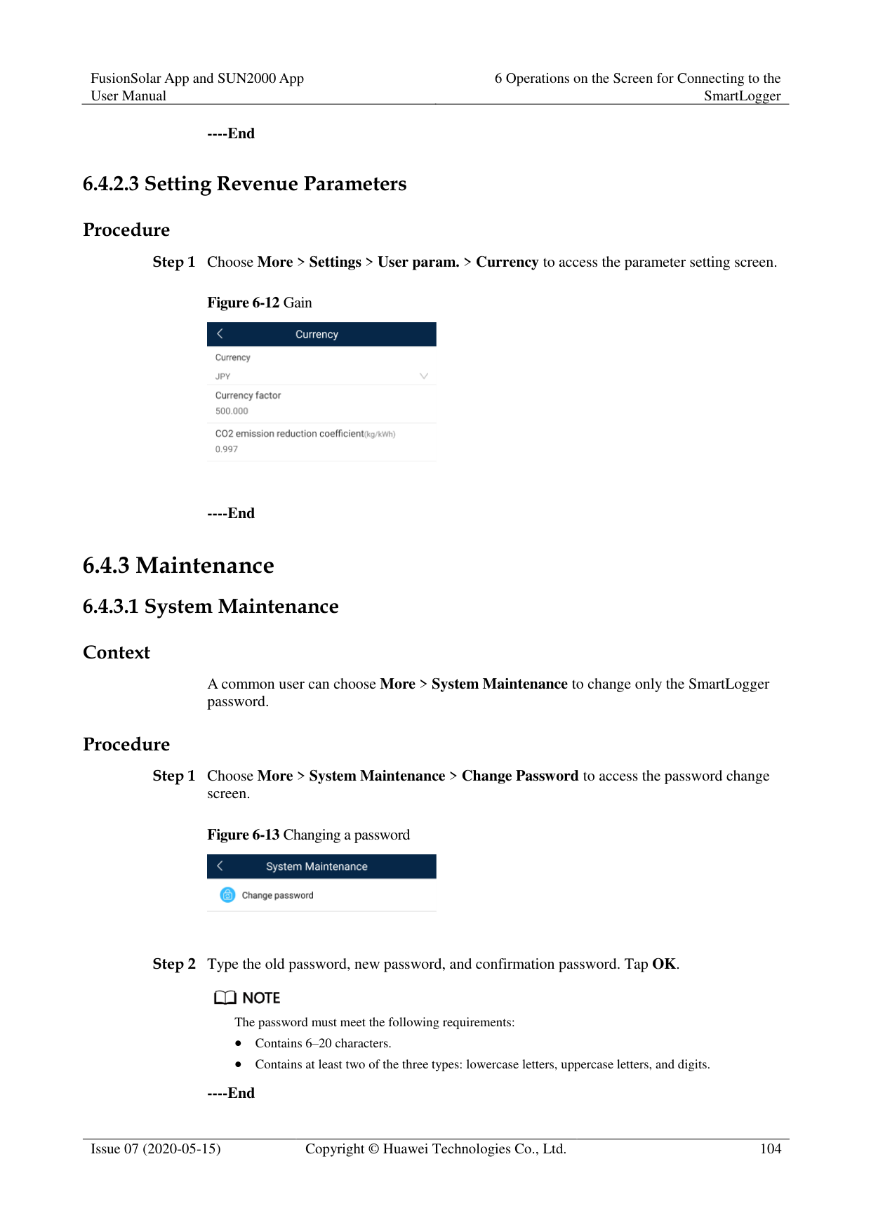

The password must meet the following requirements:
Contains 6–20 characters.
Contains at least two of the three types: lowercase letters, uppercase letters, and digits.
########### ----End
####### 6.4.3.2 Feedback
######## Context
Users can provide feedback in text, pictures, and files.

Do not add private data. Procedure

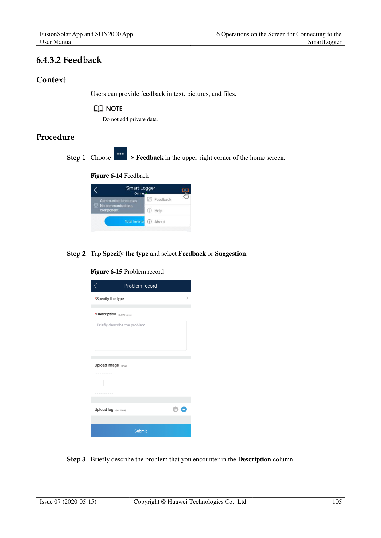
Figure 6-14 Feedback

Figure 6-15 Problem record


----End
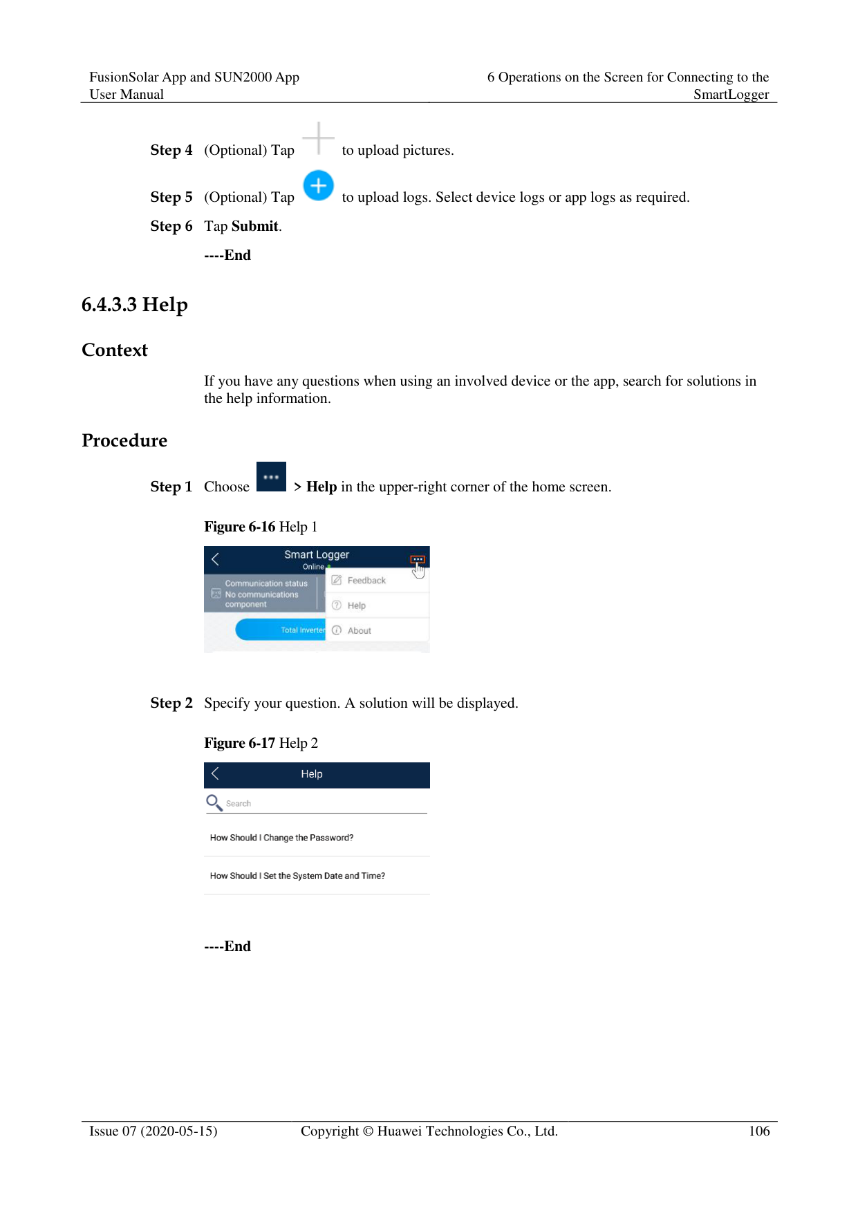
####### 6.4.3.3 Help
######## Context
If you have any questions when using an involved device or the app, search for solutions in the help information.
######## Procedure

Step 1 Choose > Help in the upper-right corner of the home screen.

Step 2 Specify your question. A solution will be displayed.

----End
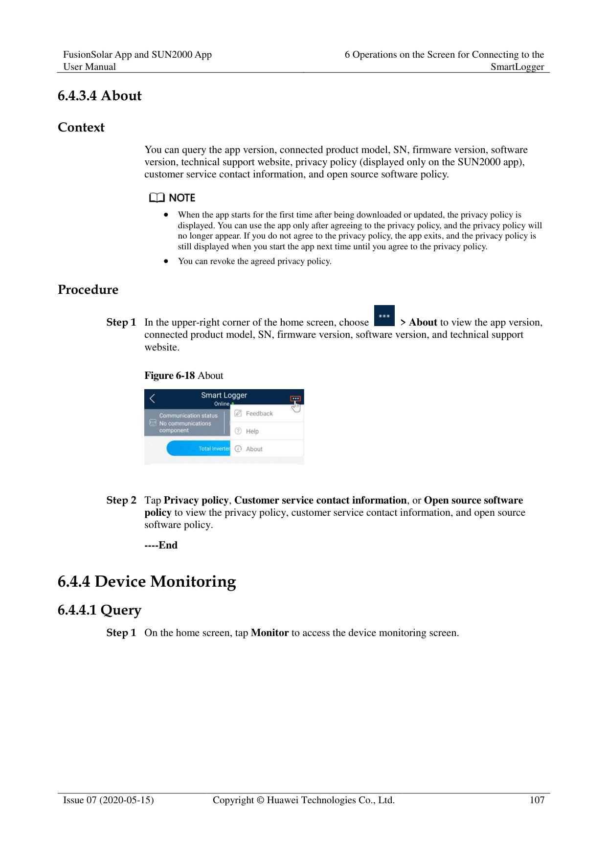
####### 6.4.3.4 About
######## Context
You can query the app version, connected product model, SN, firmware version, software version, technical support website, privacy policy (displayed only on the SUN2000 app), customer service contact information, and open source software policy.

When the app starts for the first time after being downloaded or updated, the privacy policy is displayed. You can use the app only after agreeing to the privacy policy, and the privacy policy will no longer appear. If you do not agree to the privacy policy, the app exits, and the privacy policy is still displayed when you start the app next time until you agree to the privacy policy.
You can revoke the agreed privacy policy. Procedure

Figure 6-18 About

----End
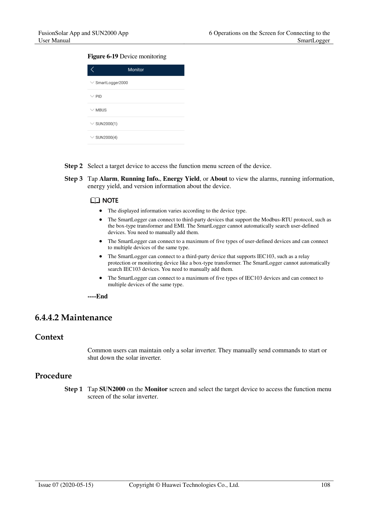
##### 6.4.4 Device Monitoring
####### 6.4.4.1 Query


The displayed information varies according to the device type.
The SmartLogger can connect to third-party devices that support the Modbus-RTU protocol, such as the box-type transformer and EMI. The SmartLogger cannot automatically search user-defined devices. You need to manually add them.
The SmartLogger can connect to a maximum of five types of user-defined devices and can connect to multiple devices of the same type.
The SmartLogger can connect to a third-party device that supports IEC103, such as a relay protection or monitoring device like a box-type transformer. The SmartLogger cannot automatically search IEC103 devices. You need to manually add them.
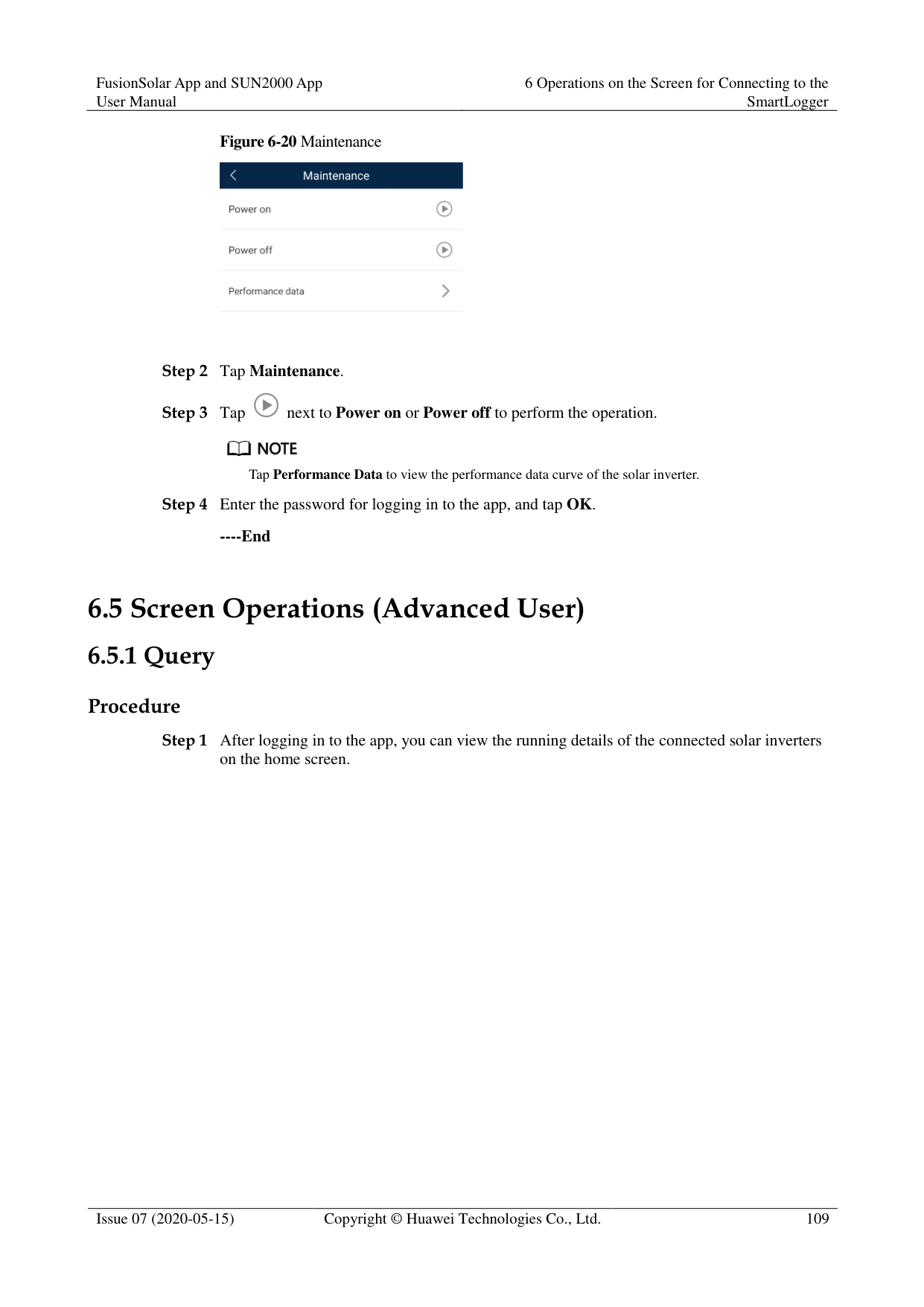
The SmartLogger can connect to a maximum of five types of IEC103 devices and can connect to multiple devices of the same type.
----End
####### 6.4.4.2 Maintenance
######## Context
Common users can maintain only a solar inverter. They manually send commands to start or shut down the solar inverter.
######## Procedure


Tap Performance Data to view the performance data curve of the solar inverter.
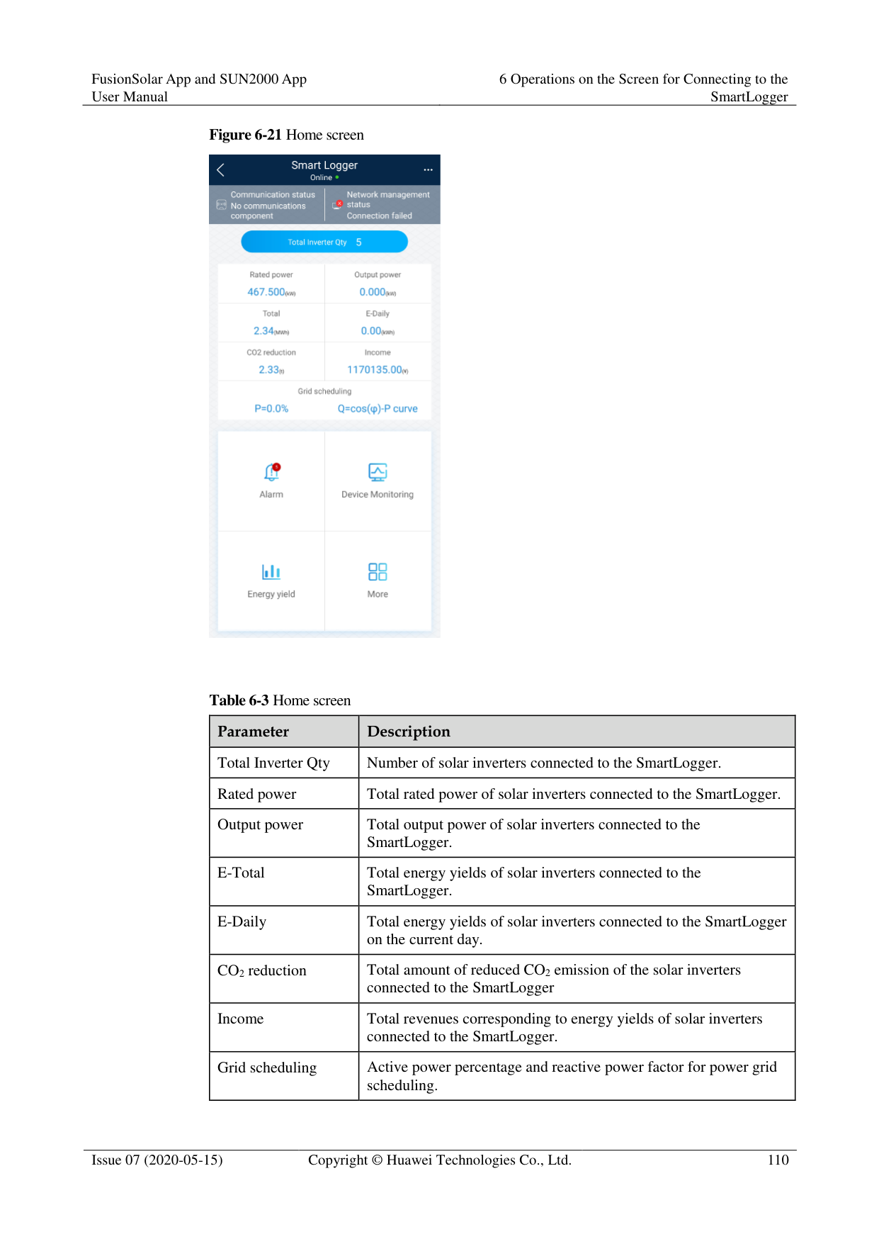

----End
#### 6.5 Screen Operations (Advanced User)
##### 6.5.1 Query
######## Procedure
Step 1 After logging in to the app, you can view the running details of the connected solar inverters
on the home screen.
Figure 6-21 Home screen

Table 6-3 Home screen
|Parameter|Description| |---|---|
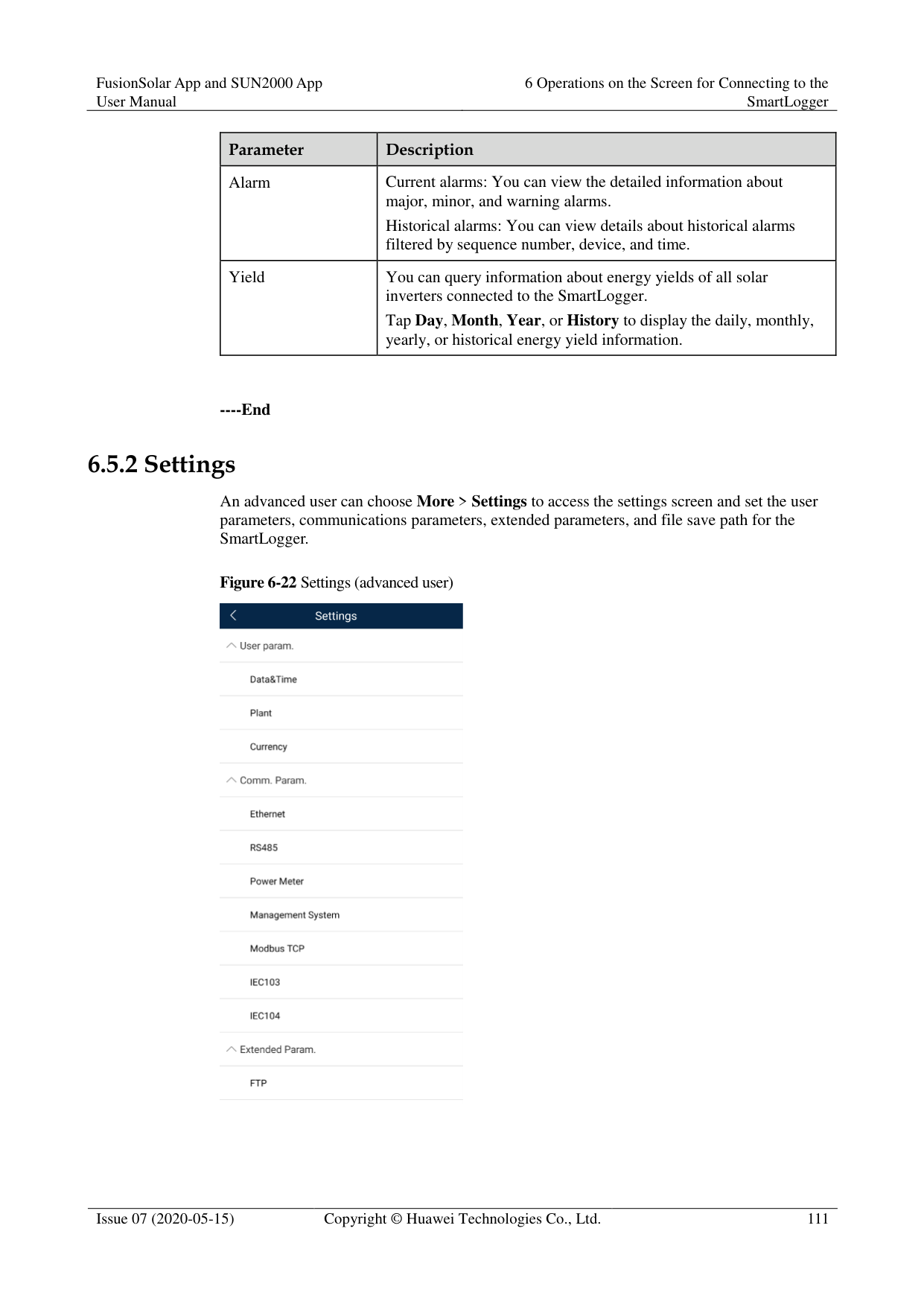
|Total Inverter Qty|Number of solar inverters connected to the SmartLogger.| |Rated power|Total rated power of solar inverters connected to the SmartLogger.| |Output power|Total output power of solar inverters connected to the SmartLogger.| |E-Total|Total energy yields of solar inverters connected to the SmartLogger.| |E-Daily|Total energy yields of solar inverters connected to the SmartLogger on the current day.| |CO2 reduction|Total amount of reduced CO2 emission of the solar inverters connected to the SmartLogger| |Income|Total revenues corresponding to energy yields of solar inverters connected to the SmartLogger.| |Grid scheduling|Active power percentage and reactive power factor for power grid scheduling.|
|Parameter|Description| |---|---| |Alarm|Current alarms: You can view the detailed information about major, minor, and warning alarms.
Historical alarms: You can view details about historical alarms filtered by sequence number, device, and time.| |Yield|You can query information about energy yields of all solar inverters connected to the SmartLogger.
Tap Day, Month, Year, or History to display the daily, monthly, yearly, or historical energy yield information.|
----End
##### 6.5.2 Settings
An advanced user can choose More > Settings to access the settings screen and set the user parameters, communications parameters, extended parameters, and file save path for the SmartLogger.
Figure 6-22 Settings (advanced user)

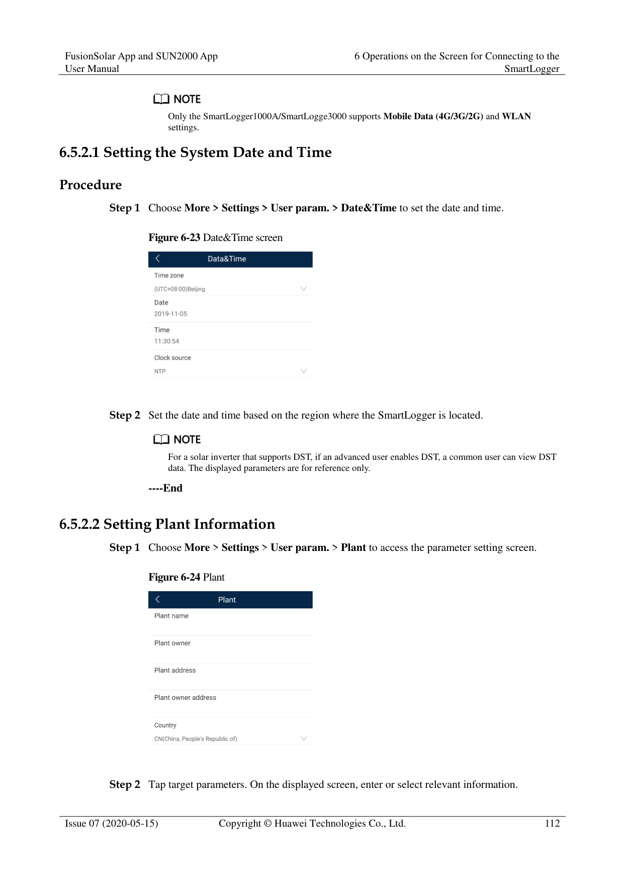
Only the SmartLogger1000A/SmartLogge3000 supports Mobile Data (4G/3G/2G) and WLAN settings.
####### 6.5.2.1 Setting the System Date and Time
Procedure
Step 1 Choose More > Settings > User param. > Date&Time to set the date and time.
Figure 6-23 Date&Time screen

Step 2 Set the date and time based on the region where the SmartLogger is located.

For a solar inverter that supports DST, if an advanced user enables DST, a common user can view DST data. The displayed parameters are for reference only.
----End
####### 6.5.2.2 Setting Plant InformationStep 1 Choose More > Settings > User param. > Plant to access the parameter setting screen.
########### Figure 6-24 Plant
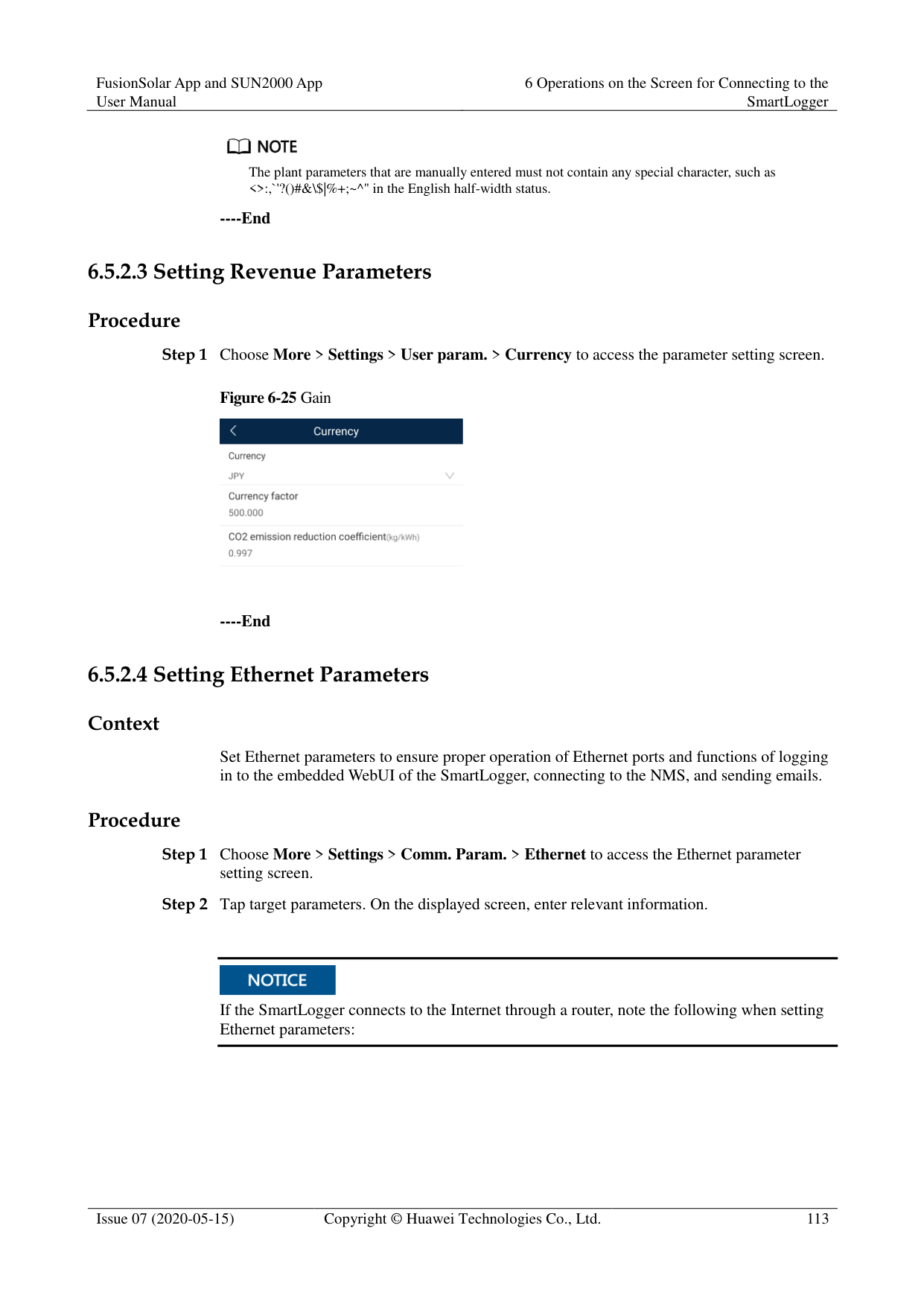

Step 2 Tap target parameters. On the displayed screen, enter or select relevant information.
The plant parameters that are manually entered must not contain any special character, such as <>:,`'?()#&\$|%+;~^" in the English half-width status.
----End
####### 6.5.2.3 Setting Revenue Parameters
Procedure
Step 1 Choose More > Settings > User param. > Currency to access the parameter setting screen.
Figure 6-25 Gain

----End
####### 6.5.2.4 Setting Ethernet Parameters
######## Context
Set Ethernet parameters to ensure proper operation of Ethernet ports and functions of logging in to the embedded WebUI of the SmartLogger, connecting to the NMS, and sending emails.
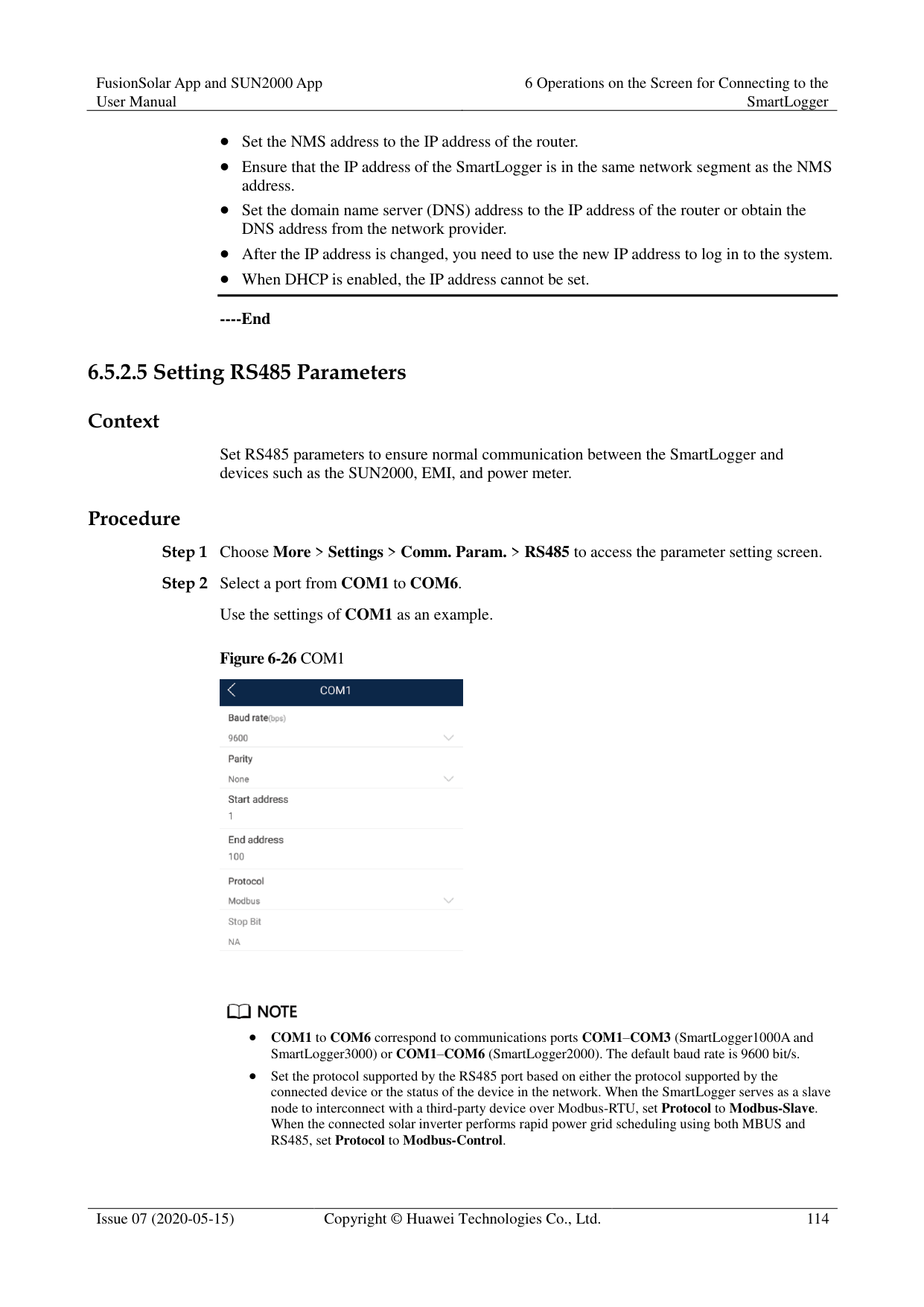
######## Procedure

If the SmartLogger connects to the Internet through a router, note the following when setting Ethernet parameters:
Set the NMS address to the IP address of the router.
Ensure that the IP address of the SmartLogger is in the same network segment as the NMS address.
Set the domain name server (DNS) address to the IP address of the router or obtain the DNS address from the network provider.
After the IP address is changed, you need to use the new IP address to log in to the system.
When DHCP is enabled, the IP address cannot be set.
----End
####### 6.5.2.5 Setting RS485 Parameters
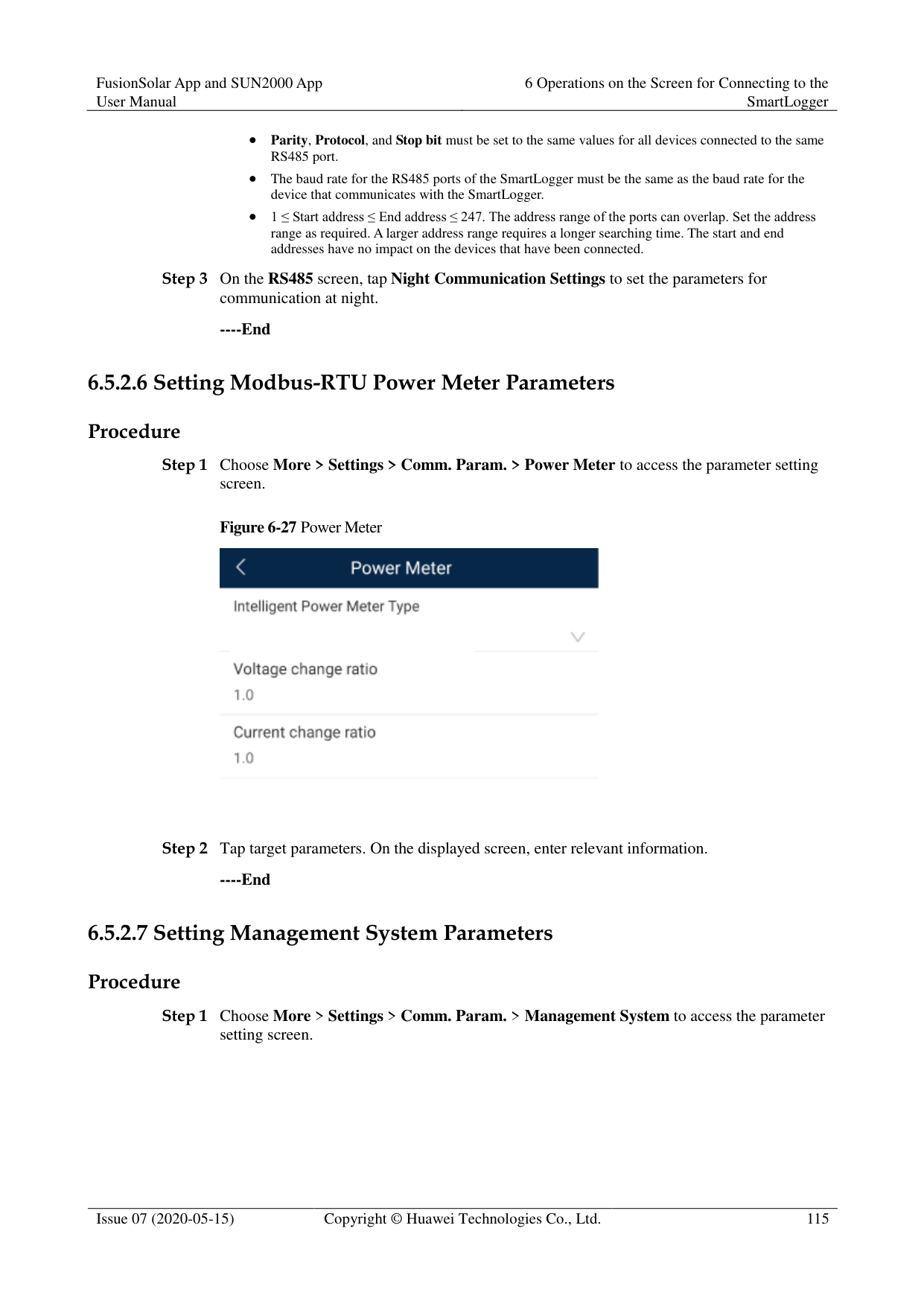
######## Context
Set RS485 parameters to ensure normal communication between the SmartLogger and devices such as the SUN2000, EMI, and power meter.
######## Procedure
########### Figure 6-26 COM1


COM1 to COM6 correspond to communications ports COM1–COM3 (SmartLogger1000A and SmartLogger3000) or COM1–COM6 (SmartLogger2000). The default baud rate is 9600 bit/s.
Set the protocol supported by the RS485 port based on either the protocol supported by the connected device or the status of the device in the network. When the SmartLogger serves as a slave node to interconnect with a third-party device over Modbus-RTU, set Protocol to Modbus-Slave. When the connected solar inverter performs rapid power grid scheduling using both MBUS and RS485, set Protocol to Modbus-Control.
Parity, Protocol, and Stop bit must be set to the same values for all devices connected to the same RS485 port.
The baud rate for the RS485 ports of the SmartLogger must be the same as the baud rate for the device that communicates with the SmartLogger.
1 ≤ Start address ≤ End address ≤ 247. The address range of the ports can overlap. Set the address range as required. A larger address range requires a longer searching time. The start and end addresses have no impact on the devices that have been connected.
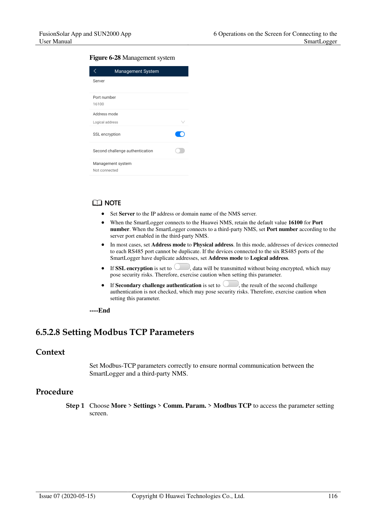
----End
####### 6.5.2.6 Setting Modbus-RTU Power Meter ParametersProcedure
Figure 6-27 Power Meter

----End
####### 6.5.2.7 Setting Management System Parameters
######## Procedure
########### Step 1 Choose More > Settings > Comm. Param. > Management System to access the parameter
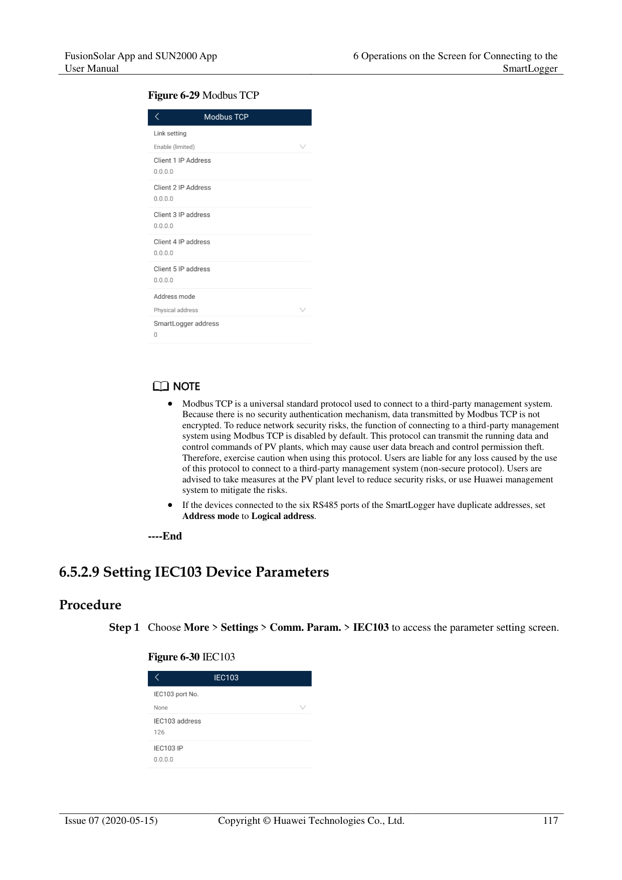
setting screen.
Figure 6-28 Management system


Set Server to the IP address or domain name of the NMS server.
When the SmartLogger connects to the Huawei NMS, retain the default value 16100 for Port number. When the SmartLogger connects to a third-party NMS, set Port number according to the server port enabled in the third-party NMS.
In most cases, set Address mode to Physical address. In this mode, addresses of devices connected to each RS485 port cannot be duplicate. If the devices connected to the six RS485 ports of the SmartLogger have duplicate addresses, set Address mode to Logical address.

If SSL encryption is set to , data will be transmitted without being encrypted, which may pose security risks. Therefore, exercise caution when setting this parameter.

If Secondary challenge authentication is set to , the result of the second challenge authentication is not checked, which may pose security risks. Therefore, exercise caution when setting this parameter.
----End
####### 6.5.2.8 Setting Modbus TCP Parameters
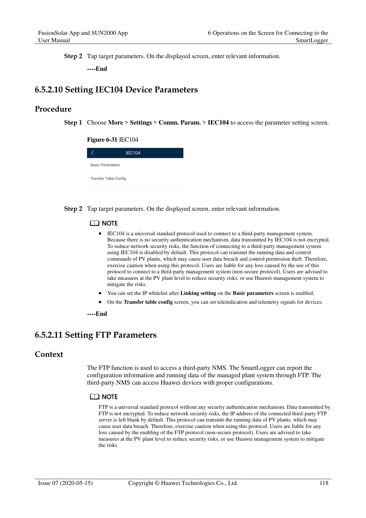
######## Context
Set Modbus-TCP parameters correctly to ensure normal communication between the SmartLogger and a third-party NMS.
######## Procedure
########### Step 1 Choose More > Settings > Comm. Param. > Modbus TCP to access the parameter setting
screen.
Figure 6-29 Modbus TCP


Modbus TCP is a universal standard protocol used to connect to a third-party management system. Because there is no security authentication mechanism, data transmitted by Modbus TCP is not encrypted. To reduce network security risks, the function of connecting to a third-party management system using Modbus TCP is disabled by default. This protocol can transmit the running data and control commands of PV plants, which may cause user data breach and control permission theft. Therefore, exercise caution when using this protocol. Users are liable for any loss caused by the use of this protocol to connect to a third-party management system (non-secure protocol). Users are advised to take measures at the PV plant level to reduce security risks, or use Huawei management system to mitigate the risks.
If the devices connected to the six RS485 ports of the SmartLogger have duplicate addresses, set
Address mode to Logical address.
----End
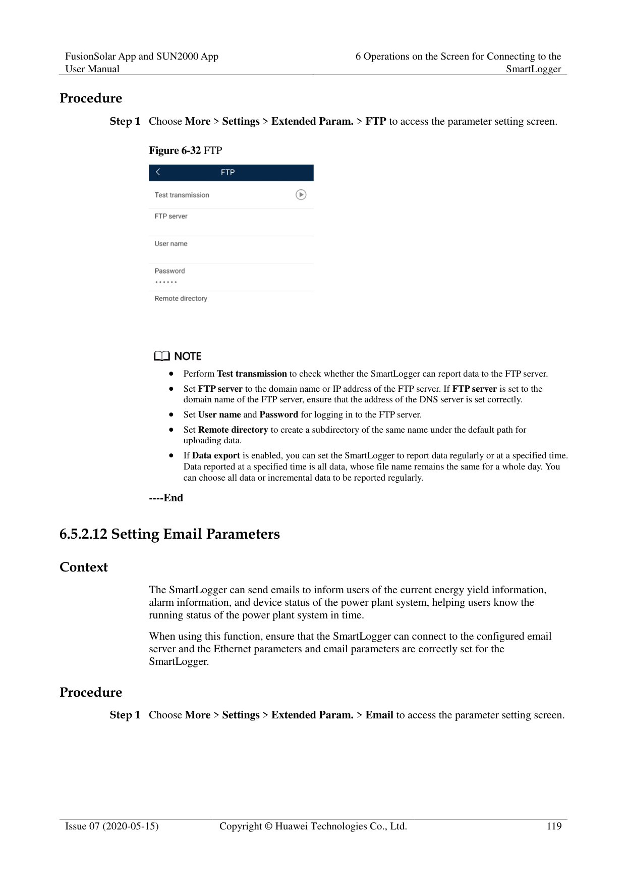
####### 6.5.2.9 Setting IEC103 Device ParametersProcedure
########### Figure 6-30 IEC103

----End
####### 6.5.2.10 Setting IEC104 Device Parameters
Procedure
Step 1 Choose More > Settings > Comm. Param. > IEC104 to access the parameter setting screen.
Figure 6-31 IEC104

Step 2 Tap target parameters. On the displayed screen, enter relevant information.
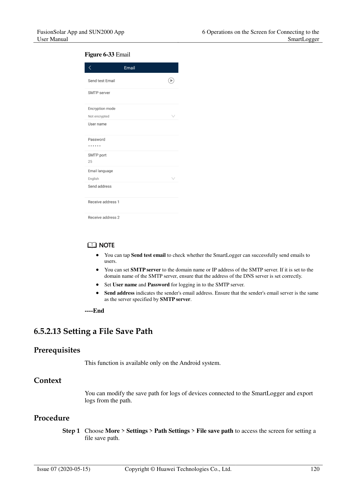

IEC104 is a universal standard protocol used to connect to a third-party management system. Because there is no security authentication mechanism, data transmitted by IEC104 is not encrypted. To reduce network security risks, the function of connecting to a third-party management system using IEC104 is disabled by default. This protocol can transmit the running data and control commands of PV plants, which may cause user data breach and control permission theft. Therefore, exercise caution when using this protocol. Users are liable for any loss caused by the use of this protocol to connect to a third-party management system (non-secure protocol). Users are advised to take measures at the PV plant level to reduce security risks, or use Huawei management system to mitigate the risks.
You can set the IP whitelist after Linking setting on the Basic parameters screen is enabled.
On the Transfer table config screen, you can set teleindication and telemetry signals for devices.
----End
####### 6.5.2.11 Setting FTP Parameters
######## Context
The FTP function is used to access a third-party NMS. The SmartLogger can report the configuration information and running data of the managed plant system through FTP. The third-party NMS can access Huawei devices with proper configurations.

FTP is a universal standard protocol without any security authentication mechanism. Data transmitted by FTP is not encrypted. To reduce network security risks, the IP address of the connected third-party FTP server is left blank by default. This protocol can transmit the running data of PV plants, which may cause user data breach. Therefore, exercise caution when using this protocol. Users are liable for any loss caused by the enabling of the FTP protocol (non-secure protocol). Users are advised to take measures at the PV plant level to reduce security risks, or use Huawei management system to mitigate the risks
######## Procedure
Step 1 Choose More > Settings > Extended Param. > FTP to access the parameter setting screen.
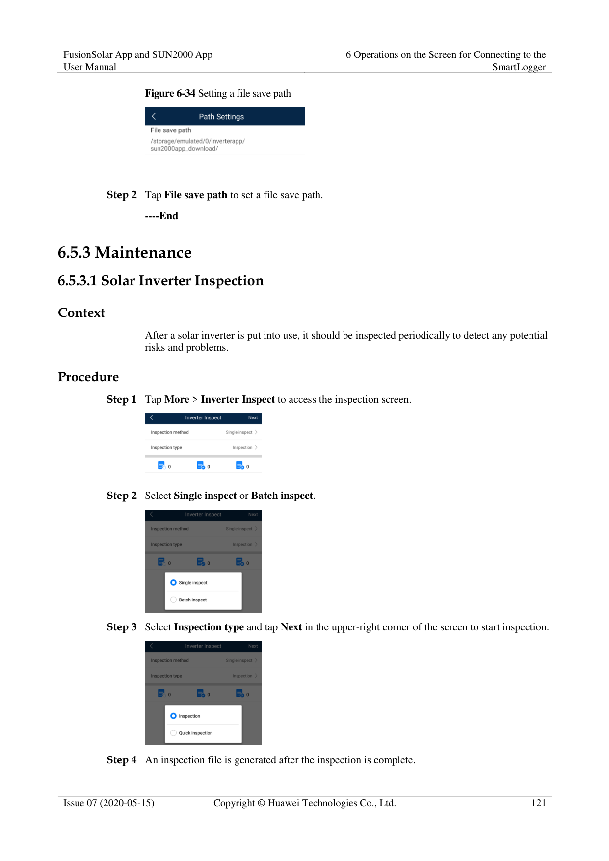
########### Figure 6-32 FTP


Perform Test transmission to check whether the SmartLogger can report data to the FTP server.
Set FTP server to the domain name or IP address of the FTP server. If FTP server is set to the domain name of the FTP server, ensure that the address of the DNS server is set correctly.
Set User name and Password for logging in to the FTP server.
Set Remote directory to create a subdirectory of the same name under the default path for uploading data.
If Data export is enabled, you can set the SmartLogger to report data regularly or at a specified time. Data reported at a specified time is all data, whose file name remains the same for a whole day. You can choose all data or incremental data to be reported regularly.
----End
####### 6.5.2.12 Setting Email Parameters
######## Context
The SmartLogger can send emails to inform users of the current energy yield information, alarm information, and device status of the power plant system, helping users know the running status of the power plant system in time.
When using this function, ensure that the SmartLogger can connect to the configured email server and the Ethernet parameters and email parameters are correctly set for the SmartLogger.
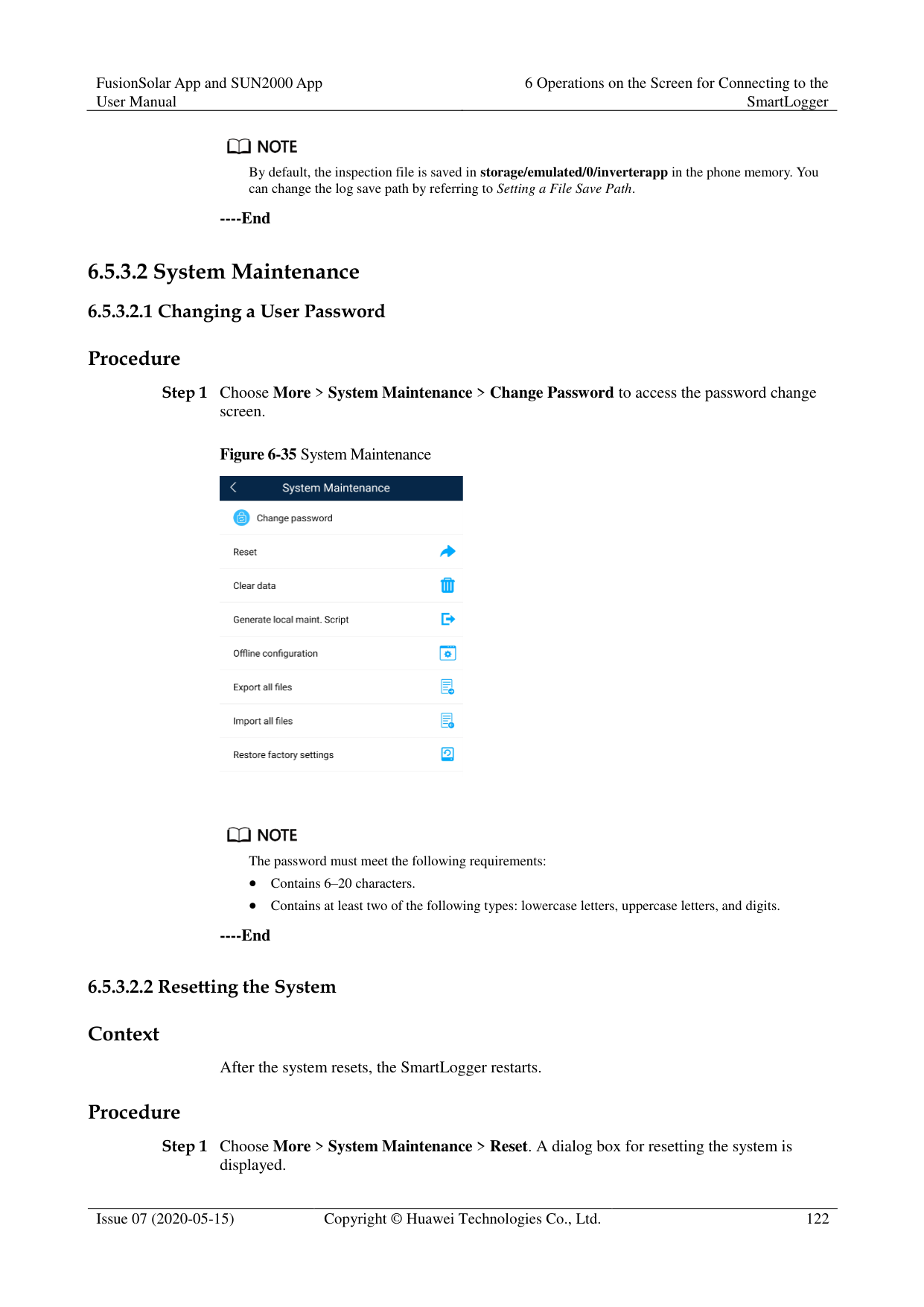
######## Procedure
Step 1 Choose More > Settings > Extended Param. > Email to access the parameter setting screen.
########### Figure 6-33 Email


You can tap Send test email to check whether the SmartLogger can successfully send emails to users.
You can set SMTP server to the domain name or IP address of the SMTP server. If it is set to the domain name of the SMTP server, ensure that the address of the DNS server is set correctly.
Set User name and Password for logging in to the SMTP server.
Send address indicates the sender's email address. Ensure that the sender's email server is the same as the server specified by SMTP server.
----End
####### 6.5.2.13 Setting a File Save Path
######## Prerequisites
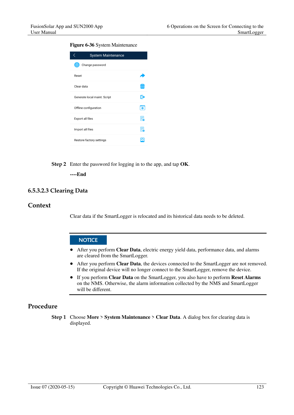
This function is available only on the Android system. Context
You can modify the save path for logs of devices connected to the SmartLogger and export logs from the path.
######## Procedure

----End
##### 6.5.3 Maintenance
####### 6.5.3.1 Solar Inverter Inspection
######## Context
After a solar inverter is put into use, it should be inspected periodically to detect any potential risks and problems.

######## Procedure


By default, the inspection file is saved in storage/emulated/0/inverterapp in the phone memory. You can change the log save path by referring to Setting a File Save Path.
----End
####### 6.5.3.2 System Maintenance
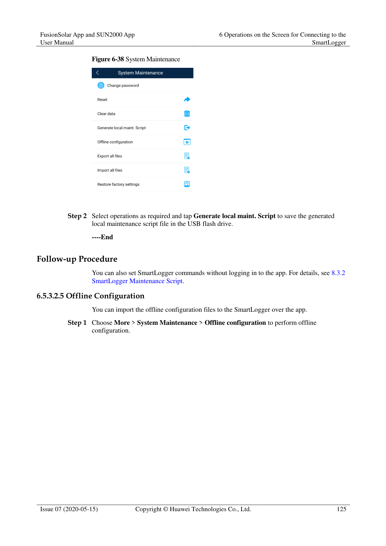
Procedure
Step 1 Choose More > System Maintenance > Change Password to access the password change
screen.
Figure 6-35 System Maintenance


The password must meet the following requirements:
Contains 6–20 characters.
Contains at least two of the following types: lowercase letters, uppercase letters, and digits.
----End
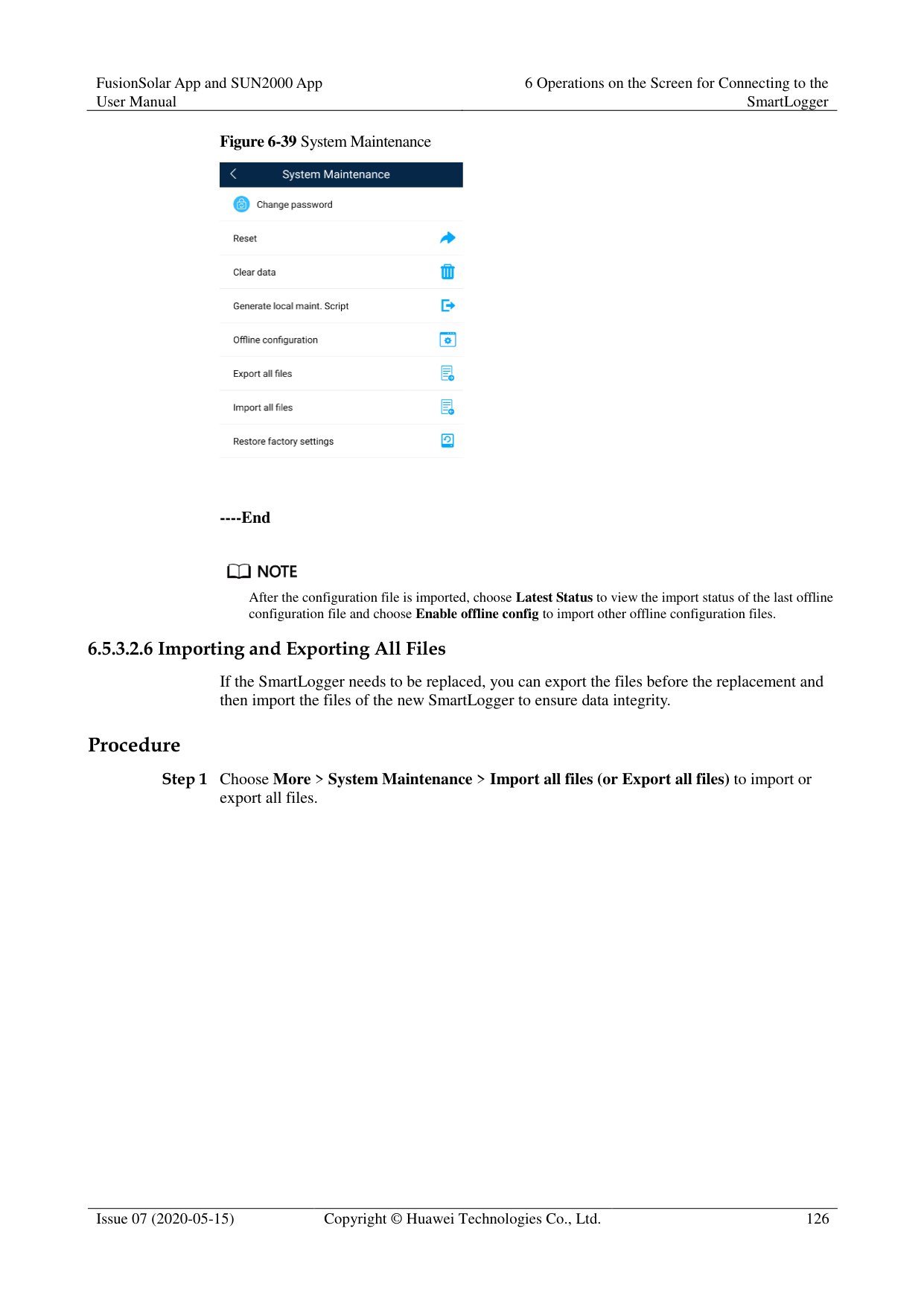
######## Context
After the system resets, the SmartLogger restarts. Procedure

----End
######## Context
Clear data if the SmartLogger is relocated and its historical data needs to be deleted.

After you perform Clear Data, electric energy yield data, performance data, and alarms are cleared from the SmartLogger.
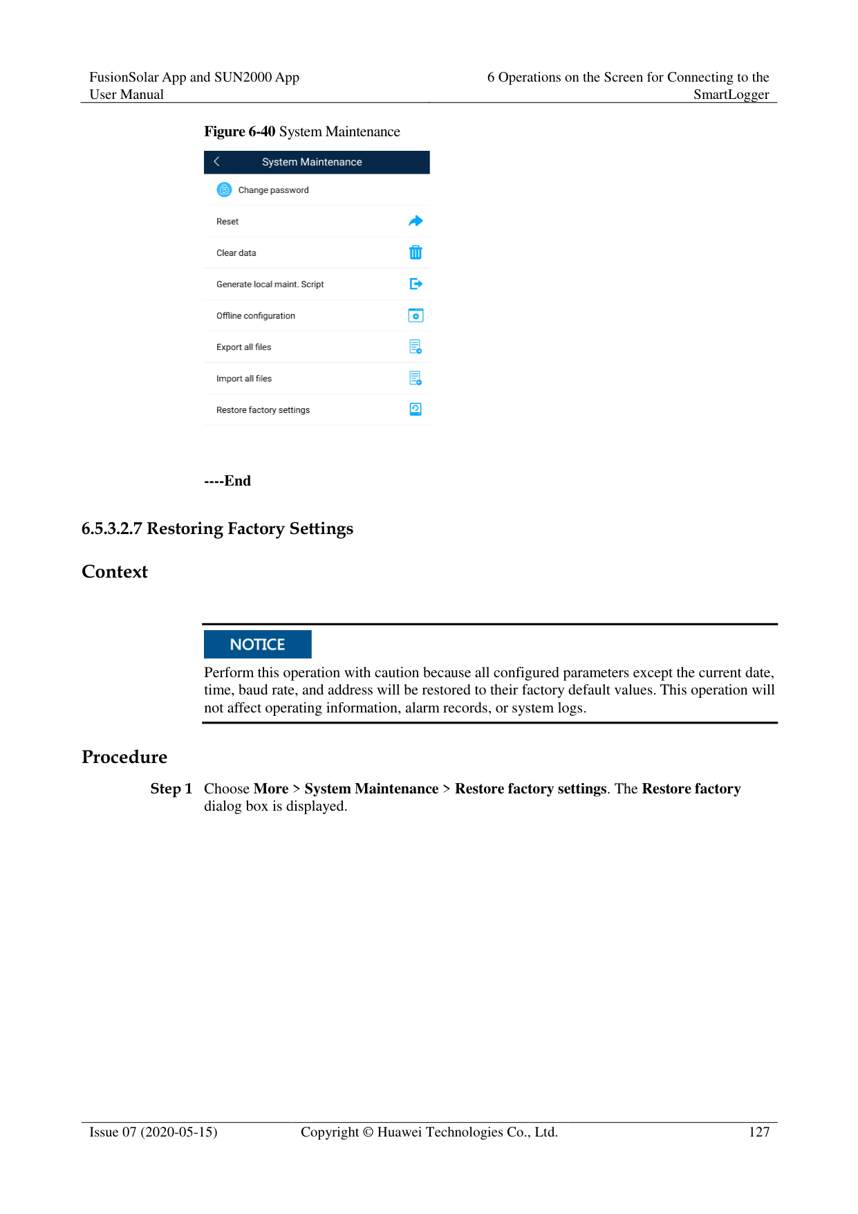
After you perform Clear Data, the devices connected to the SmartLogger are not removed. If the original device will no longer connect to the SmartLogger, remove the device.
If you perform Clear Data on the SmartLogger, you also have to perform Reset Alarms on the NMS. Otherwise, the alarm information collected by the NMS and SmartLogger will be different.
######## Procedure

----End
######## Prerequisites
A USB flash drive has been inserted into the USB port on the SmartLogger. Context
Generating the local maintenance script is used to set SmartLogger commands and save the script file in the USB flash drive. The SmartLogger executes the local script file in the USB flash drive to export SmartLogger logs, export or import all files, upgrade application software, and upgrade BSP.
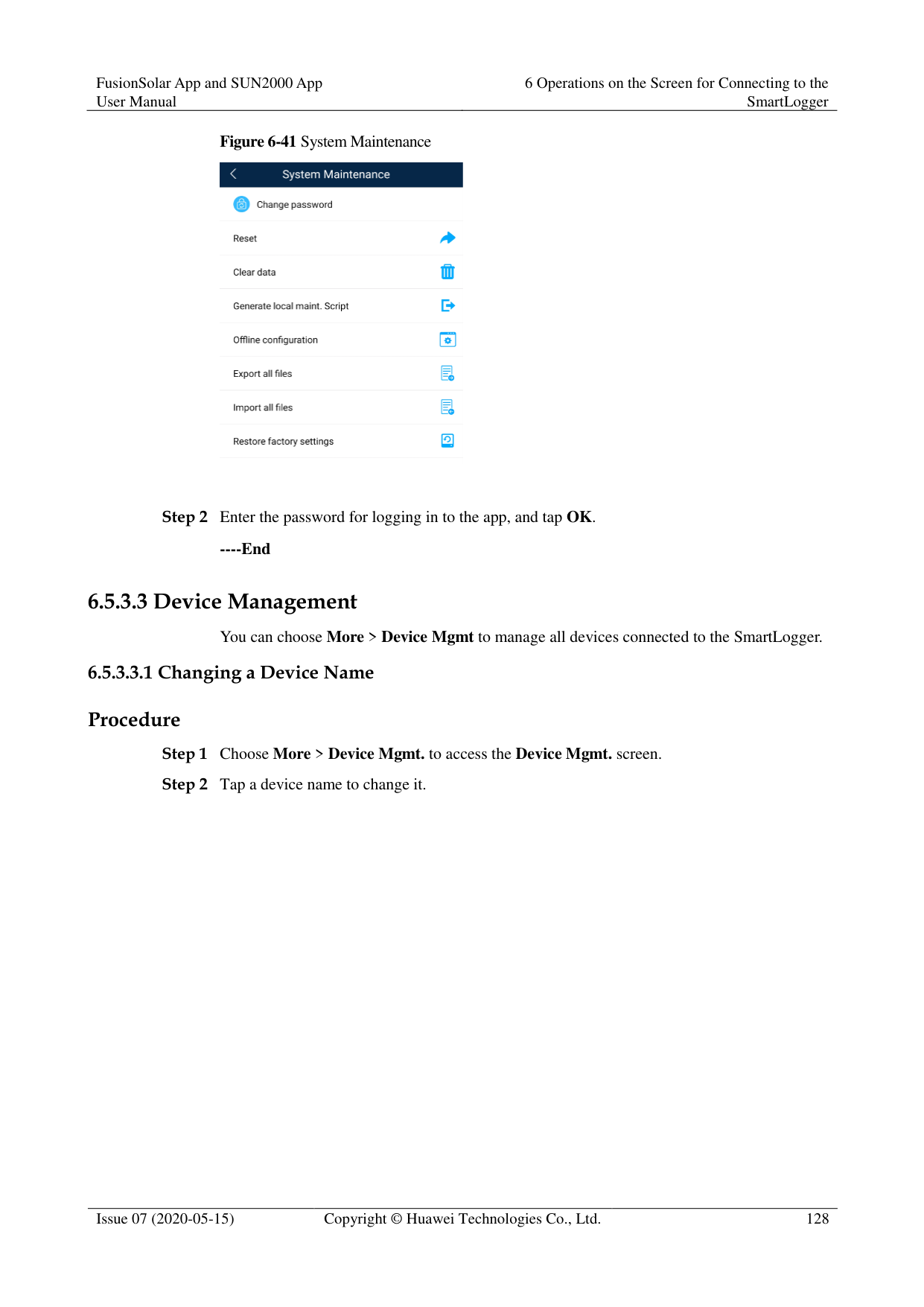
######## Procedure

----End
######## Follow-up Procedure
You can also set SmartLogger commands without logging in to the app. For details, see 8.3.2 SmartLogger Maintenance Script.
########### Step 1 Choose More > System Maintenance > Offline configuration to perform offline
configuration.


########### ----End

After the configuration file is imported, choose Latest Status to view the import status of the last offline configuration file and choose Enable offline config to import other offline configuration files.
######### 6.5.3.2.6 Importing and Exporting All Files
If the SmartLogger needs to be replaced, you can export the files before the replacement and then import the files of the new SmartLogger to ensure data integrity.
######## Procedure
########### Step 1 Choose More > System Maintenance > Import all files (or Export all files) to import or
export all files.

----End
######## 6.5.3.2.7 Restoring Factory SettingsContext

Perform this operation with caution because all configured parameters except the current date, time, baud rate, and address will be restored to their factory default values. This operation will not affect operating information, alarm records, or system logs.

######## Procedure

########### ----End
######## 6.5.3.3.1 Changing a Device NameProcedure
Figure 6-42 Changing a device name


The name of the SmartLogger cannot be changed.
----End
######### 6.5.3.3.2 Deleting Devices
Procedure Step 1 Choose More > Device Mgmt. to access the Device Mgmt. screen. Step 2 Hold down a device name, select the devices to be deleted, and tap Batch delete to delete
them.
Figure 6-43 Deleting devices


Deleted devices are not displayed on the Monitor screen.
----End

######## Context
The SmartLogger can automatically detect and connect to devices. The EMI, power meter, slave SmartLogger, and third-party devices cannot be automatically detected. You need to add them manually. For details, see 6.5.3.3.4 Manually Adding a Device.
######## Procedure

----End
######## Context
The EMI, power meter, slave SmartLogger, and third-party devices cannot be automatically detected. You need to add them manually.
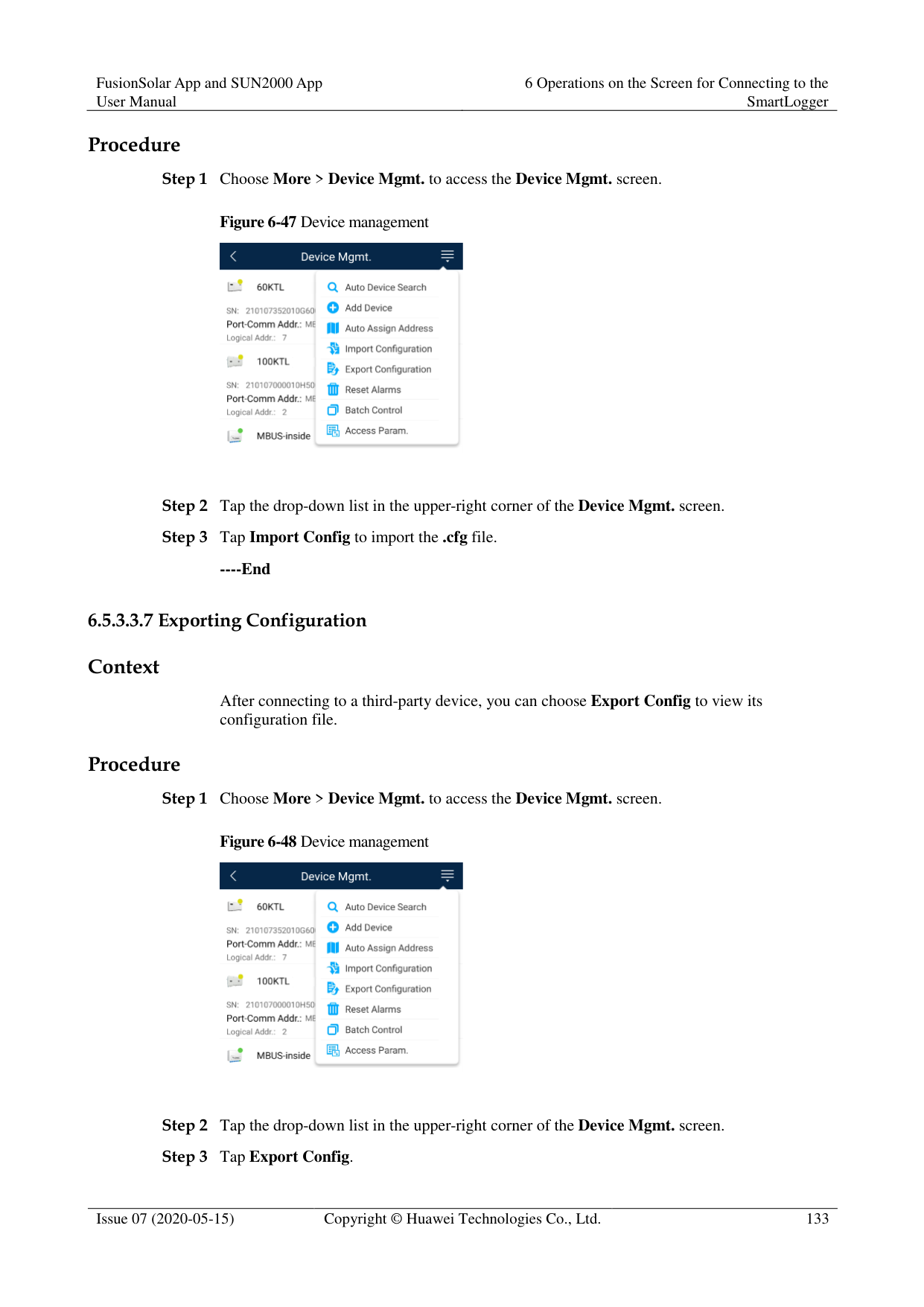
######## Procedure
Figure 6-45 Device management


Comm. Protocol is set to Modbus RTU by default. If you need to modify it, refer to 6.5.2.5 Setting RS485 Parameters.
Before adding the EMI or power meter manually, set the EMI or power meter parameters. For details, see SmartLogger3000 User Manual , SmartLogger2000 User Manual or SmartLogger1000A User Manual.
----End
Context
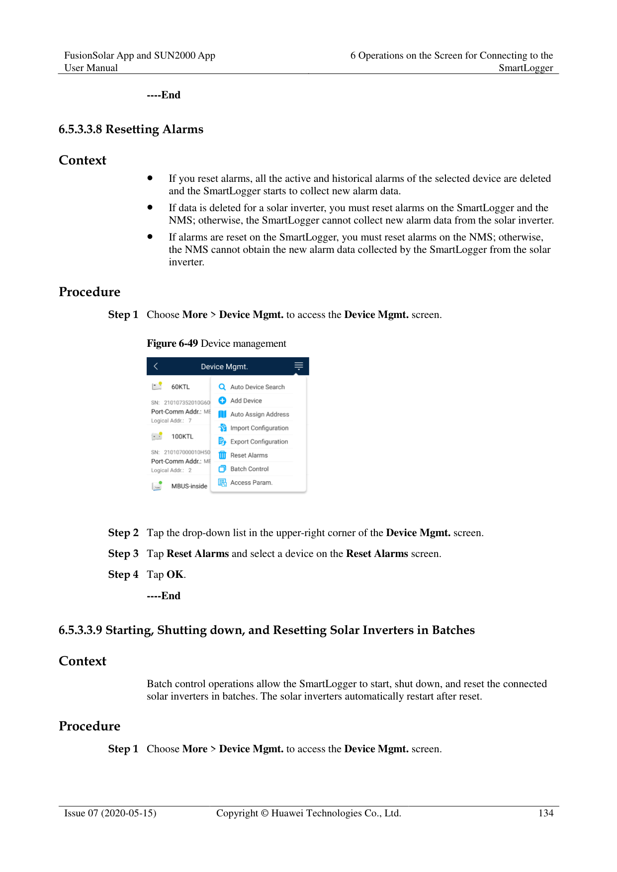
The SmartLogger can automatically allocate addresses to the connected devices and adjust the addresses based on device sequence numbers.
Procedure
Figure 6-46 Device management

----End
######## Prerequisites
The name extension of the file to be imported must be .cfg. Otherwise, the file will be unavailable.
The file to be imported is stored in the memory or SD card of the mobile phone. Context
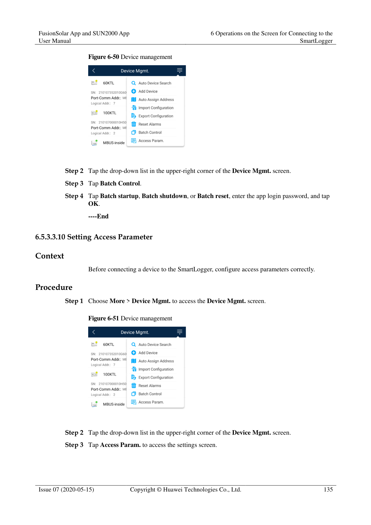
When connecting to a user-defined device or the IEC103 device, import a configuration file and add a device manually. Then, the device can be queried on the Monitor screen.
######## Procedure
Figure 6-47 Device management

----End
######## Context
After connecting to a third-party device, you can choose Export Config to view its configuration file.
######## Procedure

Figure 6-48 Device management

----End
Context
If you reset alarms, all the active and historical alarms of the selected device are deleted and the SmartLogger starts to collect new alarm data.
If data is deleted for a solar inverter, you must reset alarms on the SmartLogger and the NMS; otherwise, the SmartLogger cannot collect new alarm data from the solar inverter.
If alarms are reset on the SmartLogger, you must reset alarms on the NMS; otherwise, the NMS cannot obtain the new alarm data collected by the SmartLogger from the solar inverter.
Procedure
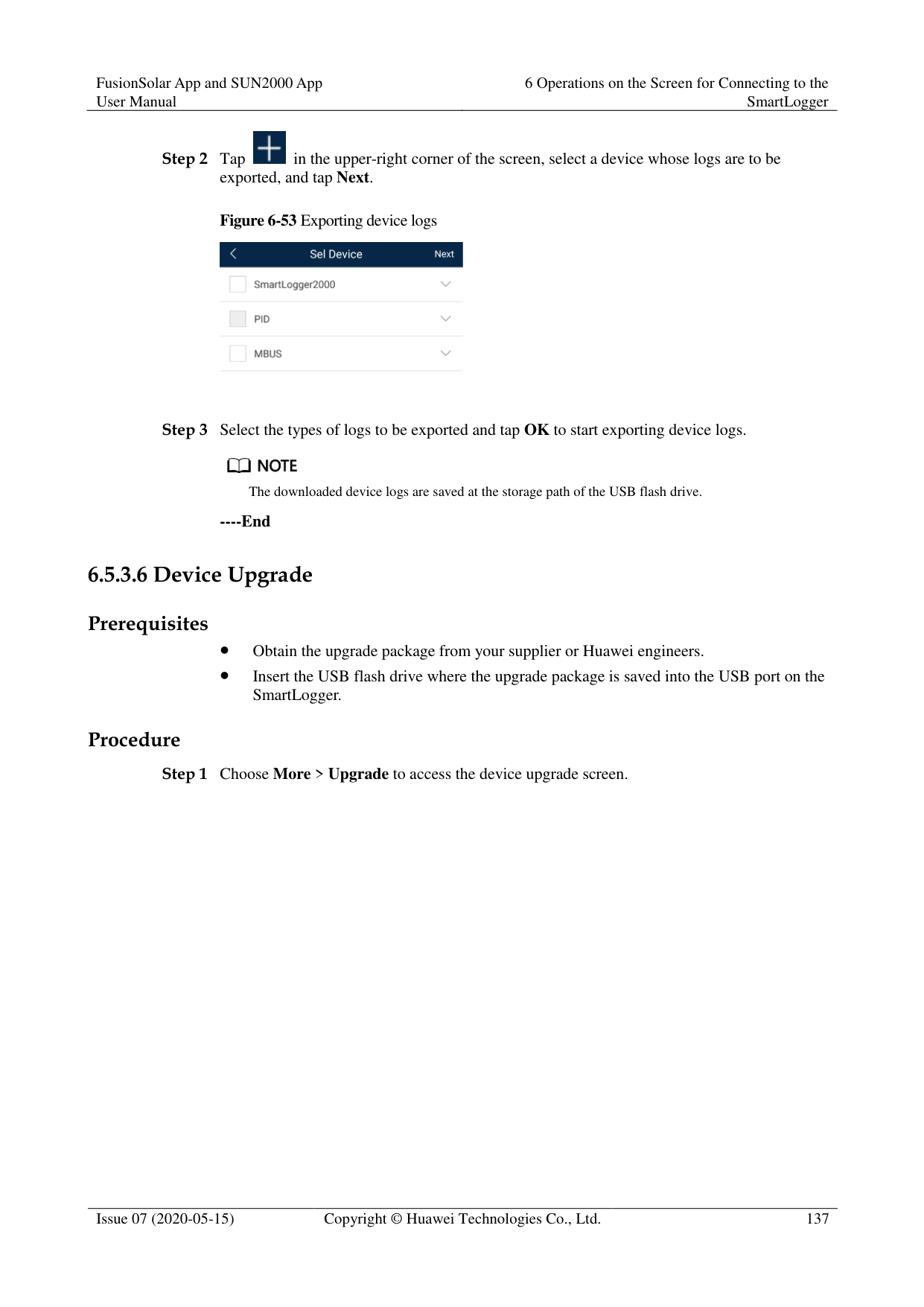
Figure 6-49 Device management

----End
######## Context
Batch control operations allow the SmartLogger to start, shut down, and reset the connected solar inverters in batches. The solar inverters automatically restart after reset.
######## Procedure
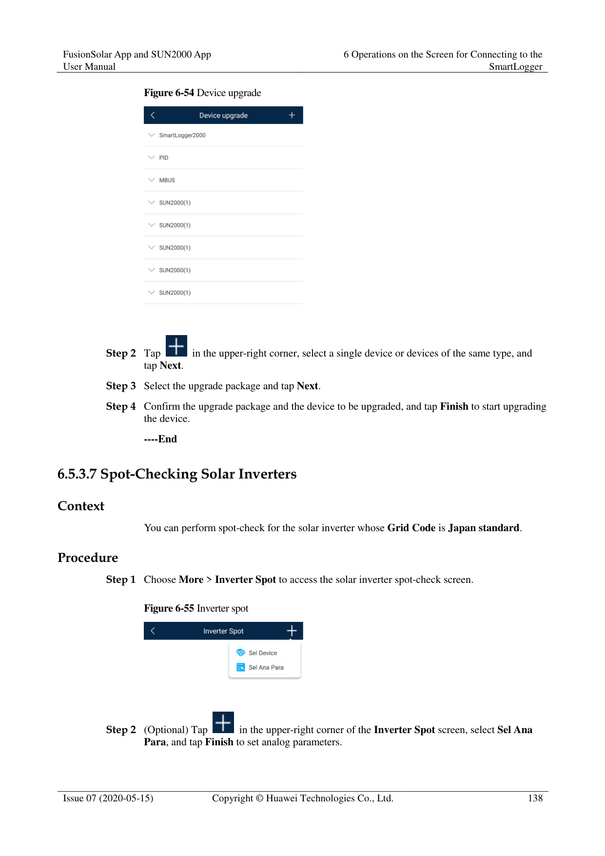

----End
######## Context
Before connecting a device to the SmartLogger, configure access parameters correctly. Procedure
Figure 6-51 Device management


If the SmartLogger communicates with the solar inverter over the MBUS, set Embedded MBUS enable to Enable.
----End
####### 6.5.3.4 Managing the Device List
Context
On the device list screen, you can choose Export Device Info > Edit Device Info File > Import Device Info to modify device information in the information file.
Procedure
Figure 6-52 Device List


The exported device information file is in .csv format.
----End
####### 6.5.3.5 Exporting Device Logs
######## Prerequisites
A USB flash drive has been inserted into the USB port on the SmartLogger. Procedure


Figure 6-53 Exporting device logs


The downloaded device logs are saved at the storage path of the USB flash drive.
----End
####### 6.5.3.6 Device Upgrade
######## Prerequisites
Obtain the upgrade package from your supplier or Huawei engineers.
Insert the USB flash drive where the upgrade package is saved into the USB port on the
######## SmartLogger. Procedure


----End
####### 6.5.3.7 Spot-Checking Solar Inverters
######## Context
You can perform spot-check for the solar inverter whose Grid Code is Japan standard. Procedure
Figure 6-55 Inverter spot


After the parameters on the Sel Analog Para screen are set, the analog parameters and their values are displayed on the solar inverter spot-check screen. You can also tap Sel Device to set parameters when the solar inverters are being spot-checked.

----End
####### 6.5.3.8 Feedback
######## Context
Users can provide feedback in text, pictures, and files.

Do not add private data. Procedure

Figure 6-56 Feedback


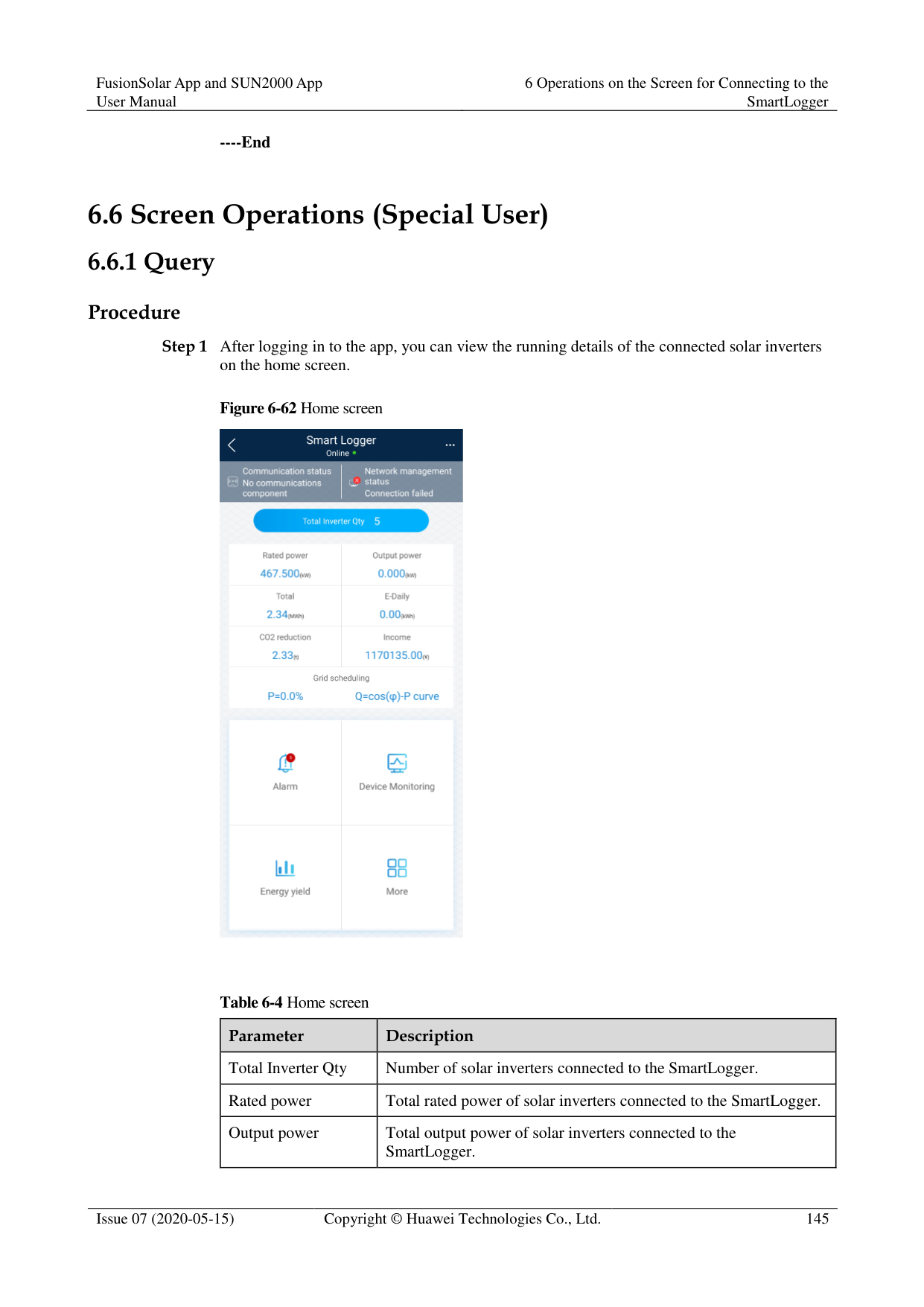


----End
####### 6.5.3.9 Help
######## Context
If you have any questions when using an involved device or the app, search for solutions in the help information.
######## Procedure


Step 2 Specify your question. A solution will be displayed.

----End
####### 6.5.3.10 About
######## Context
You can query the app version, connected product model, SN, firmware version, software version, technical support website, privacy policy (displayed only on the SUN2000 app), customer service contact information, and open source software policy.

When the app starts for the first time after being downloaded or updated, the privacy policy is displayed. You can use the app only after agreeing to the privacy policy, and the privacy policy will no longer appear. If you do not agree to the privacy policy, the app exits, and the privacy policy is still displayed when you start the app next time until you agree to the privacy policy.
You can revoke the agreed privacy policy. Procedure

Step 1 In the upper-right corner of the home screen, choose > About to view the app version, connected product model, SN, firmware version, software version, and technical support website.
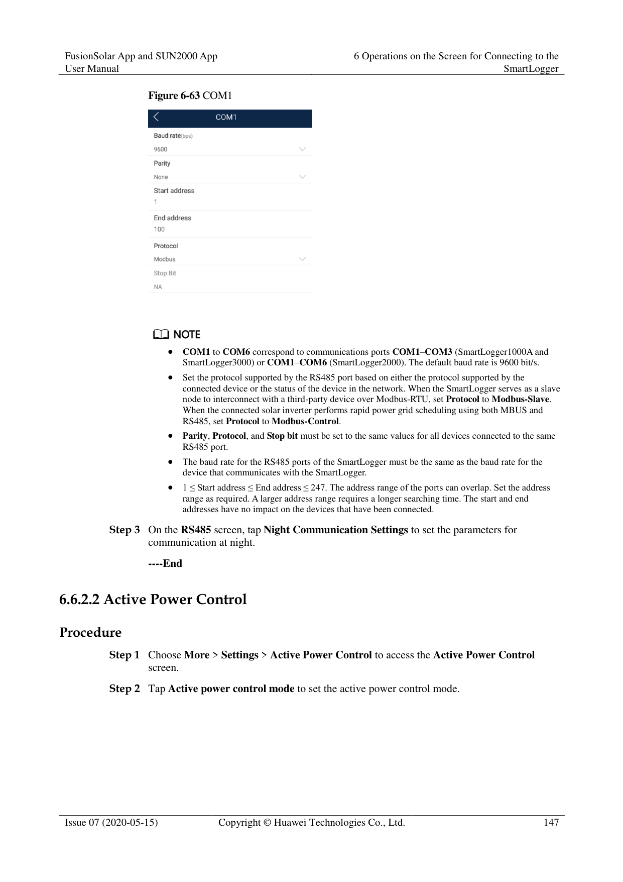
########### Figure 6-60 About

Step 2 Tap Privacy policy, Customer service contact information, or Open source software policy to view the privacy policy, customer service contact information, and open source software policy.
----End
##### 6.5.4 Device Monitoring
An advanced user can tap Monitor to query the running information and alarms about the SmartLogger and the devices connected to it, set parameters, and send commands.
Figure 6-61 Device monitoring

Step 2 Select a target device to access the function menu screen of the device. Step 3 Tap Alarm, Running Info., Energy Yield, or About to view the alarms, running information,
energy yield, and version information about the device.

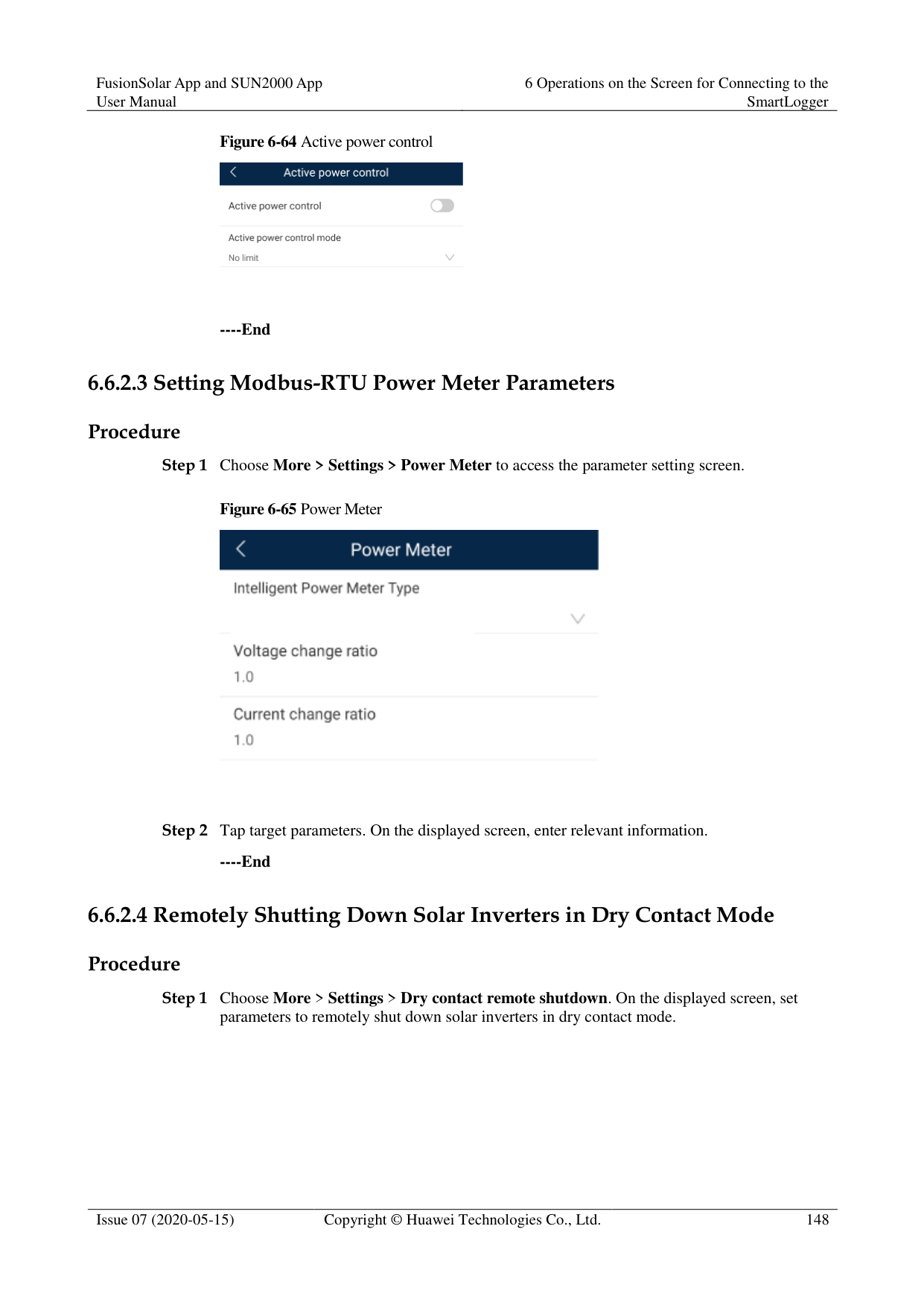
The displayed information varies according to the device type.
The SmartLogger can connect to third-party devices that support the Modbus-RTU protocol, such as the box-type transformer and EMI. The SmartLogger cannot automatically search user-defined devices. You need to manually add them.
The SmartLogger can connect to a maximum of five types of user-defined devices and can connect to multiple devices of the same type.
The SmartLogger can connect to a third-party device that supports IEC103, such as a relay protection or monitoring device like a box-type transformer. The SmartLogger cannot automatically search IEC103 devices. You need to manually add them.
The SmartLogger can connect to a maximum of five types of IEC103 devices and can connect to multiple devices of the same type.
----End
####### 6.5.4.2 Settings
Context
An advanced user can set solar inverter parameters, MBUS parameters, PID Module parameters and DL/T645 parameters.
Procedure
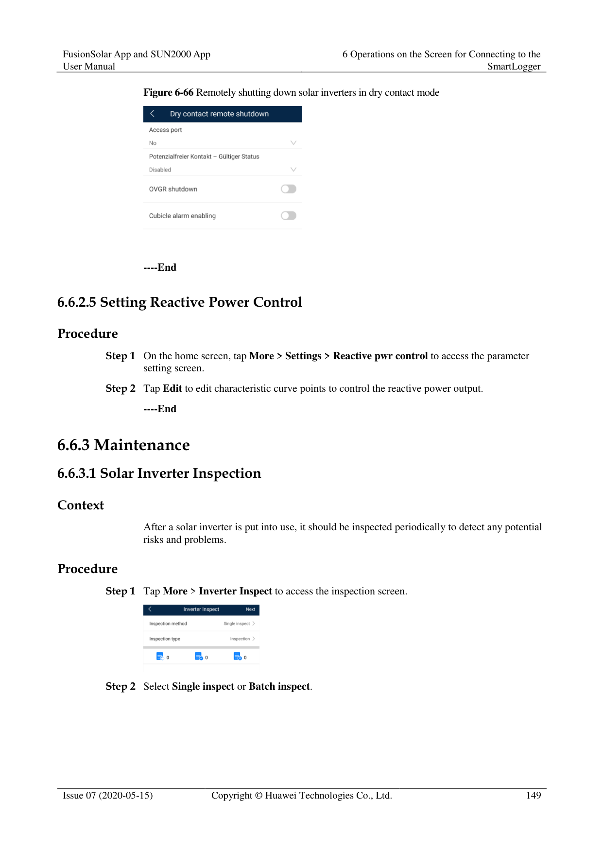

For Setting MBUS Parameters, set Anti-crosstalk to Enable to make devices in the anti-crosstalk list take effect.
----End
####### 6.5.4.3 Maintenance
######## Context
An advanced user can download only the logs of the SmartLogger, solar inverter, MBUS, and PID module.
######## Procedure

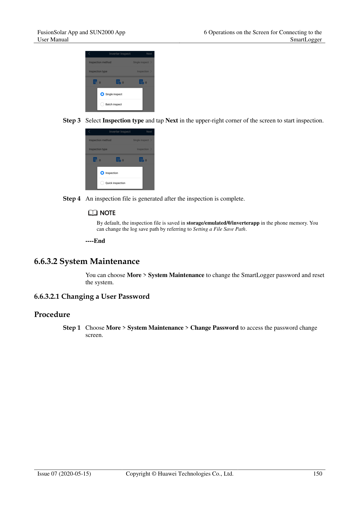
By default, Android system logs are saved in the storage/emulated/0/inverterapp folder in the phone memory. You can change the save path by referring to "Setting a File Save Path".
The downloaded solar inverter logs are saved at the Device Log directory in File Manager in your mobile phone. You can also send the logs to your mailbox for checking.
########### ----End
######## 6.5.4.3.2 Solar Inverter MaintenanceProcedure


AFCI self-check is available only for the solar inverter model marked with -US.
Tap License Management or Performance Data to view the certificate information and performance data curve of the solar inverter.
----End
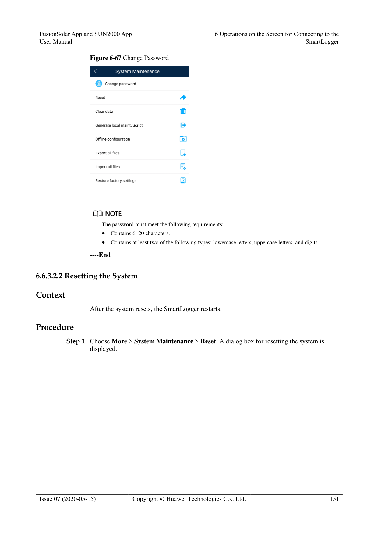
######## 6.5.4.3.3 MBUS MaintenanceProcedure


----End
######## 6.5.4.3.4 PID Module MaintenanceProcedure

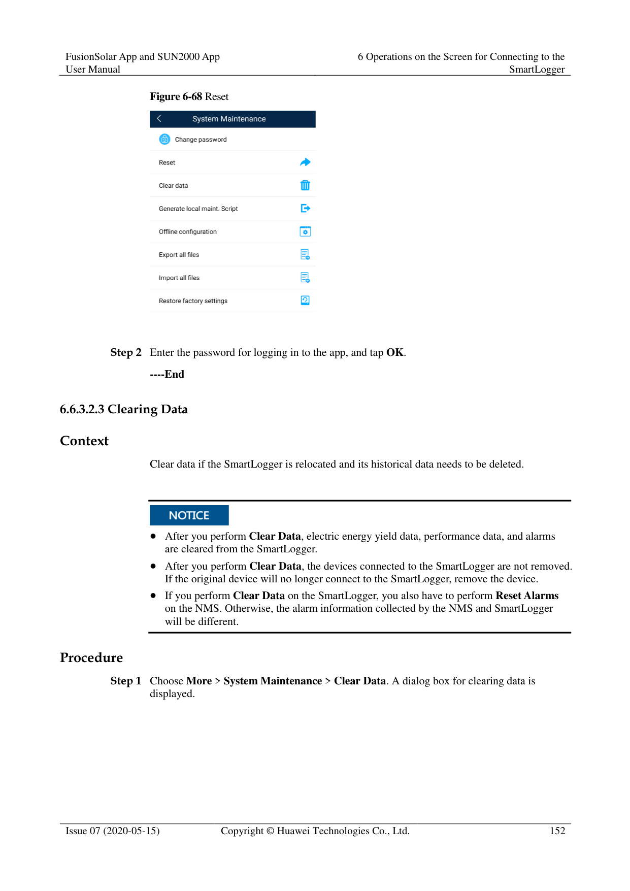

If you clear data, active and historical alarms stored on the PID module will all be cleared.
Tap Performance Data to view the performance data curve of the PID module.
----End
#### 6.6 Screen Operations (Special User)
##### 6.6.1 Query
######## Procedure
Step 1 After logging in to the app, you can view the running details of the connected solar inverters
on the home screen.
Figure 6-62 Home screen

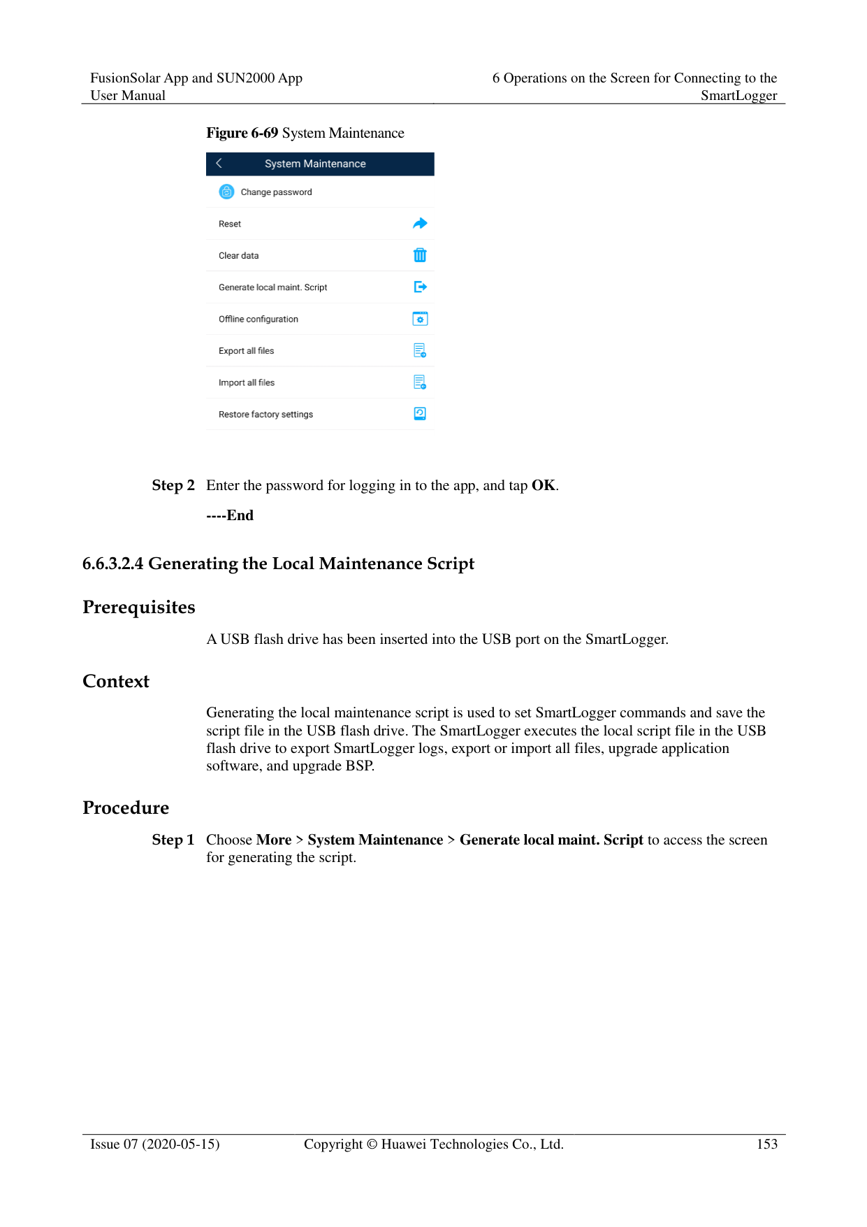
Table 6-4 Home screen
|Parameter|Description| |---|---| |Total Inverter Qty|Number of solar inverters connected to the SmartLogger.| |Rated power|Total rated power of solar inverters connected to the SmartLogger.| |Output power|Total output power of solar inverters connected to the SmartLogger.|
|Parameter|Description| |---|---| |E-Total|Total energy yields of solar inverters connected to the SmartLogger.| |E-Daily|Total energy yields of solar inverters connected to the SmartLogger on the current day.| |CO2 reduction|Total amount of reduced CO2 emission of the solar inverters connected to the SmartLogger| |Income|Total revenues corresponding to energy yields of solar inverters connected to the SmartLogger.| |Grid scheduling|Active power percentage and reactive power factor for power grid scheduling.| |Alarm|Current alarms: You can view the detailed information about major, minor, and warning alarms.
Historical alarms: You can view details about historical alarms filtered by sequence number, device, and time.| |Yield|You can query information about energy yields of all solar inverters connected to the SmartLogger.
Tap Day, Month, Year, or History to display the daily, monthly, yearly, or historical energy yield information.|
----End
##### 6.6.2 Settings
####### 6.6.2.1 Setting RS485 Parameters
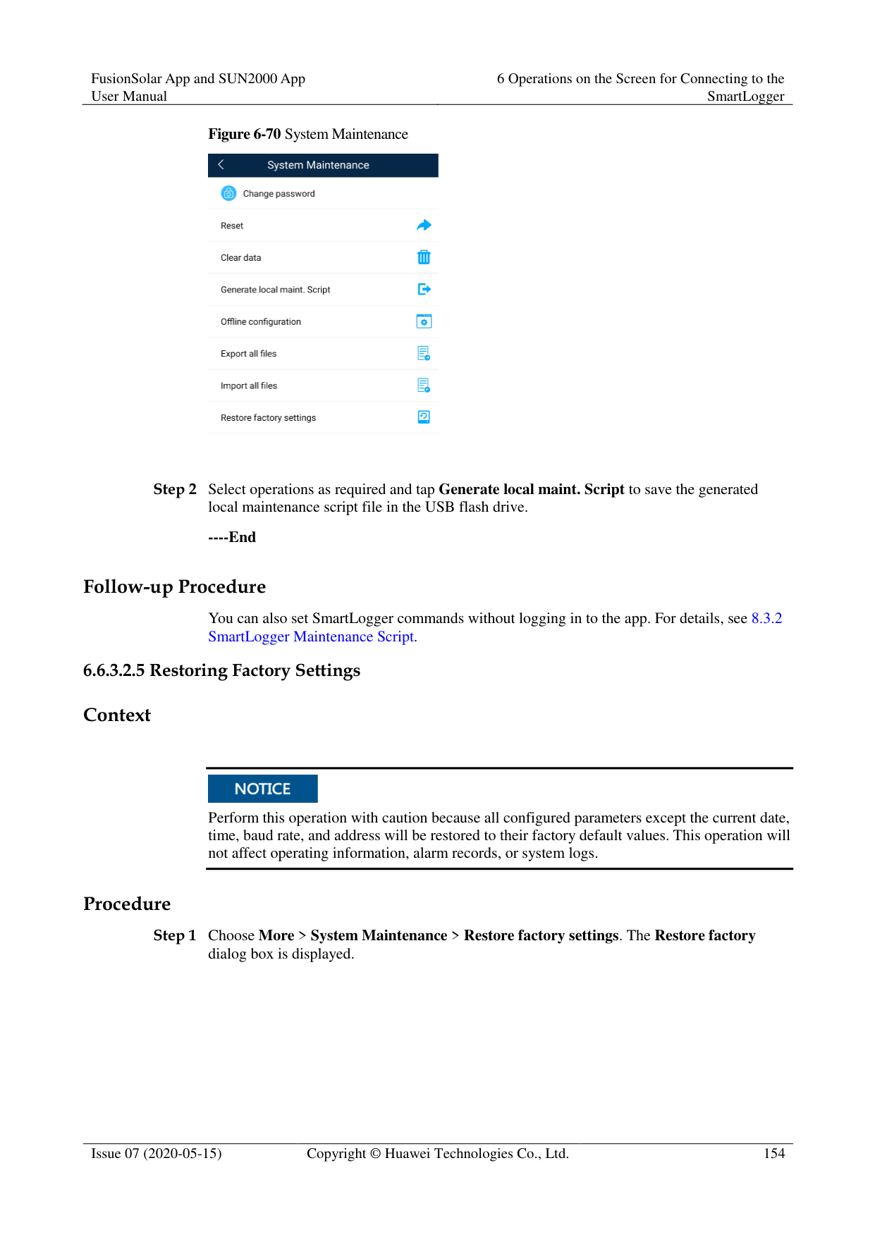
######## Context
Set RS485 parameters to ensure normal communication between the SmartLogger and devices such as the SUN2000, EMI, and power meter.
######## Procedure
########### Figure 6-63 COM1


COM1 to COM6 correspond to communications ports COM1 COM3 (SmartLogger1000A and SmartLogger3000) or COM1–COM6 (SmartLogger2000). The default baud rate is 9600 bit/s.
Set the protocol supported by the RS485 port based on either the protocol supported by the connected device or the status of the device in the network. When the SmartLogger serves as a slave node to interconnect with a third-party device over Modbus-RTU, set Protocol to Modbus-Slave. When the connected solar inverter performs rapid power grid scheduling using both MBUS and RS485, set Protocol to Modbus-Control.
Parity, Protocol, and Stop bit must be set to the same values for all devices connected to the same RS485 port.
The baud rate for the RS485 ports of the SmartLogger must be the same as the baud rate for the device that communicates with the SmartLogger.

1 ≤ Start address ≤ End address ≤ 247. The address range of the ports can overlap. Set the address range as required. A larger address range requires a longer searching time. The start and end addresses have no impact on the devices that have been connected.
----End
####### 6.6.2.2 Active Power ControlProcedure
Figure 6-64 Active power control

----End
####### 6.6.2.3 Setting Modbus-RTU Power Meter ParametersProcedure
Figure 6-65 Power Meter
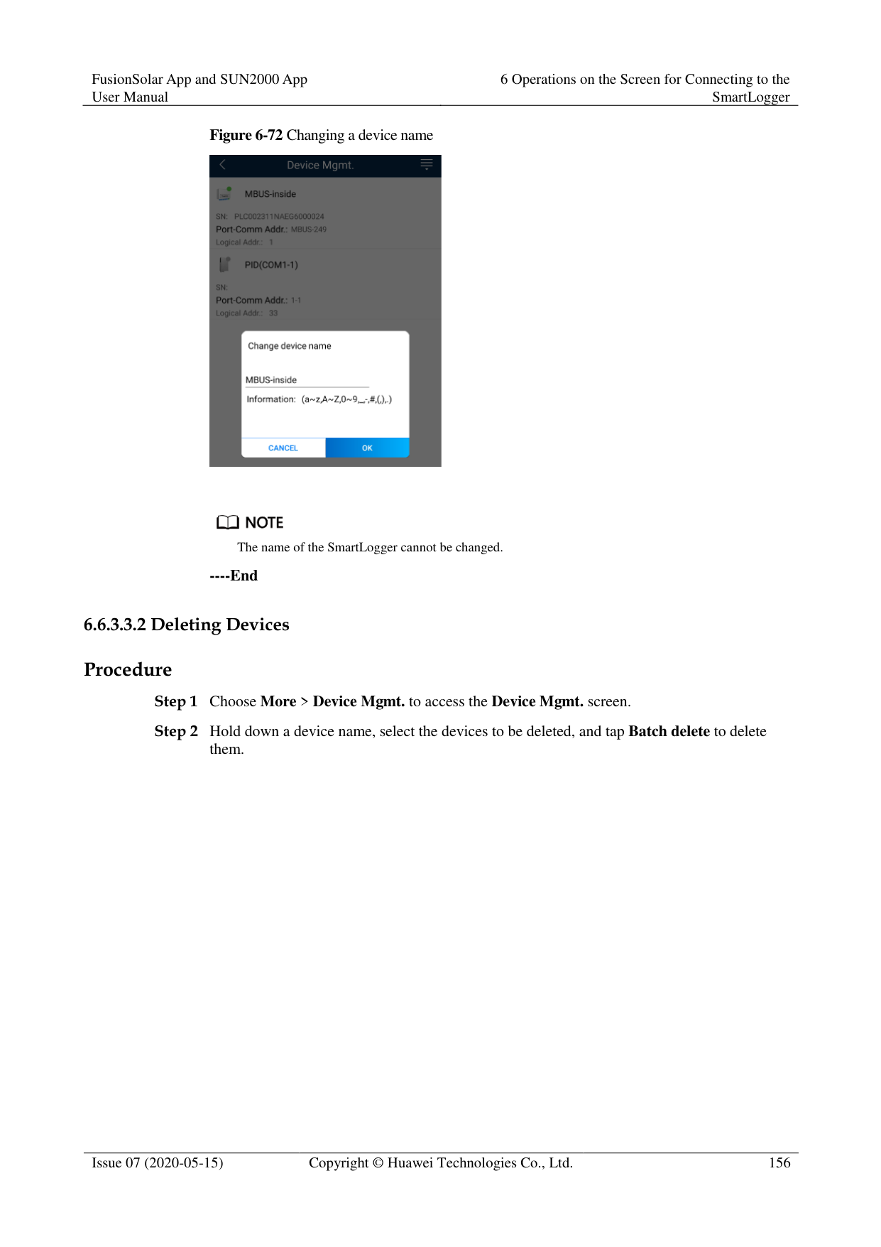

----End
####### 6.6.2.4 Remotely Shutting Down Solar Inverters in Dry Contact Mode
######## Procedure
########### Step 1 Choose More > Settings > Dry contact remote shutdown. On the displayed screen, set
parameters to remotely shut down solar inverters in dry contact mode.
Figure 6-66 Remotely shutting down solar inverters in dry contact mode

----End
####### 6.6.2.5 Setting Reactive Power ControlProcedure
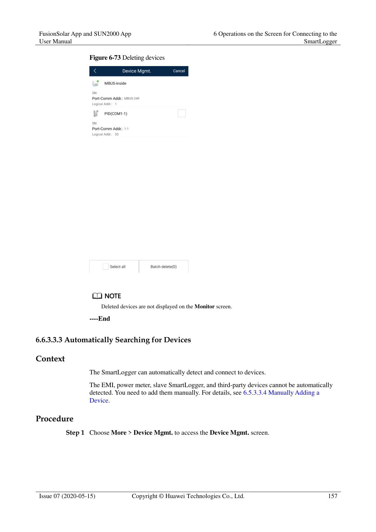
----End
##### 6.6.3 Maintenance
####### 6.6.3.1 Solar Inverter Inspection
######## Context
After a solar inverter is put into use, it should be inspected periodically to detect any potential risks and problems.
######## Procedure


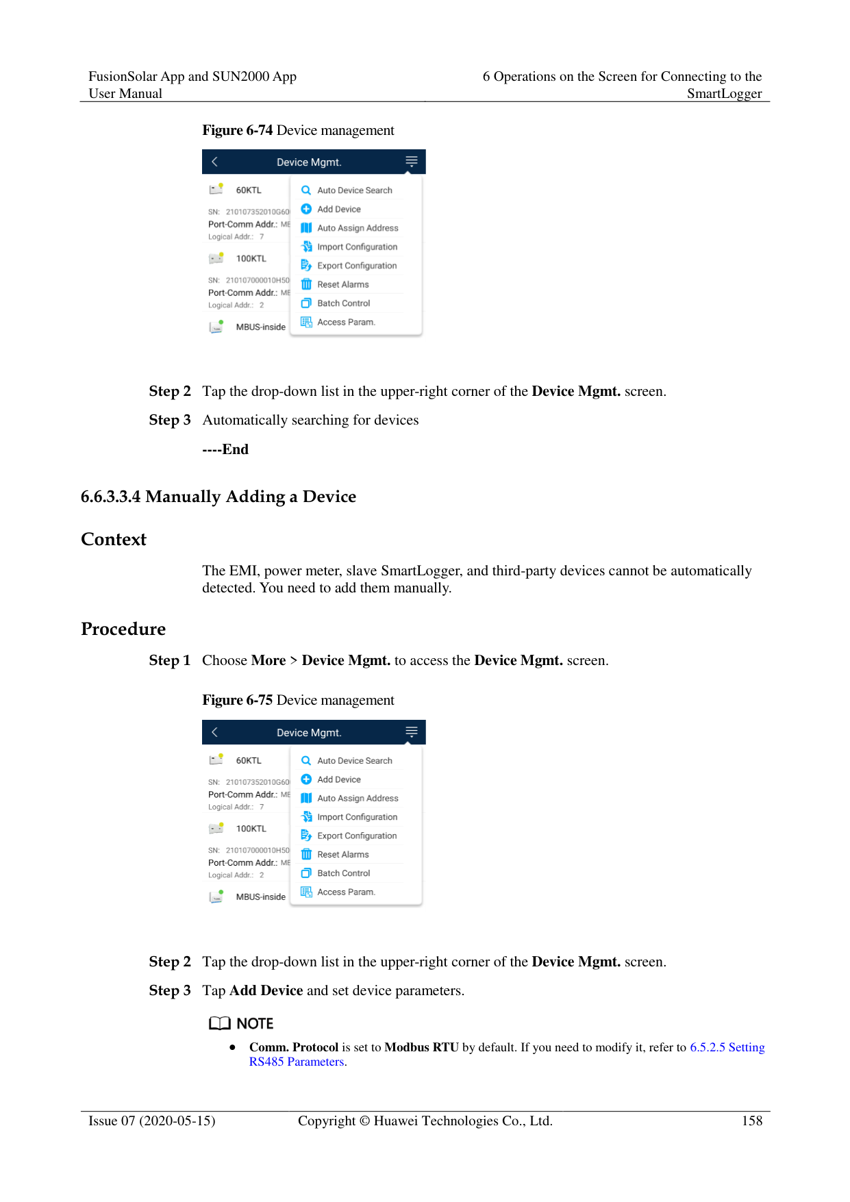


By default, the inspection file is saved in storage/emulated/0/inverterapp in the phone memory. You can change the log save path by referring to Setting a File Save Path.
----End
####### 6.6.3.2 System Maintenance
You can choose More > System Maintenance to change the SmartLogger password and reset the system.
######## Procedure
########### Step 1 Choose More > System Maintenance > Change Password to access the password change
screen.
Figure 6-67 Change Password
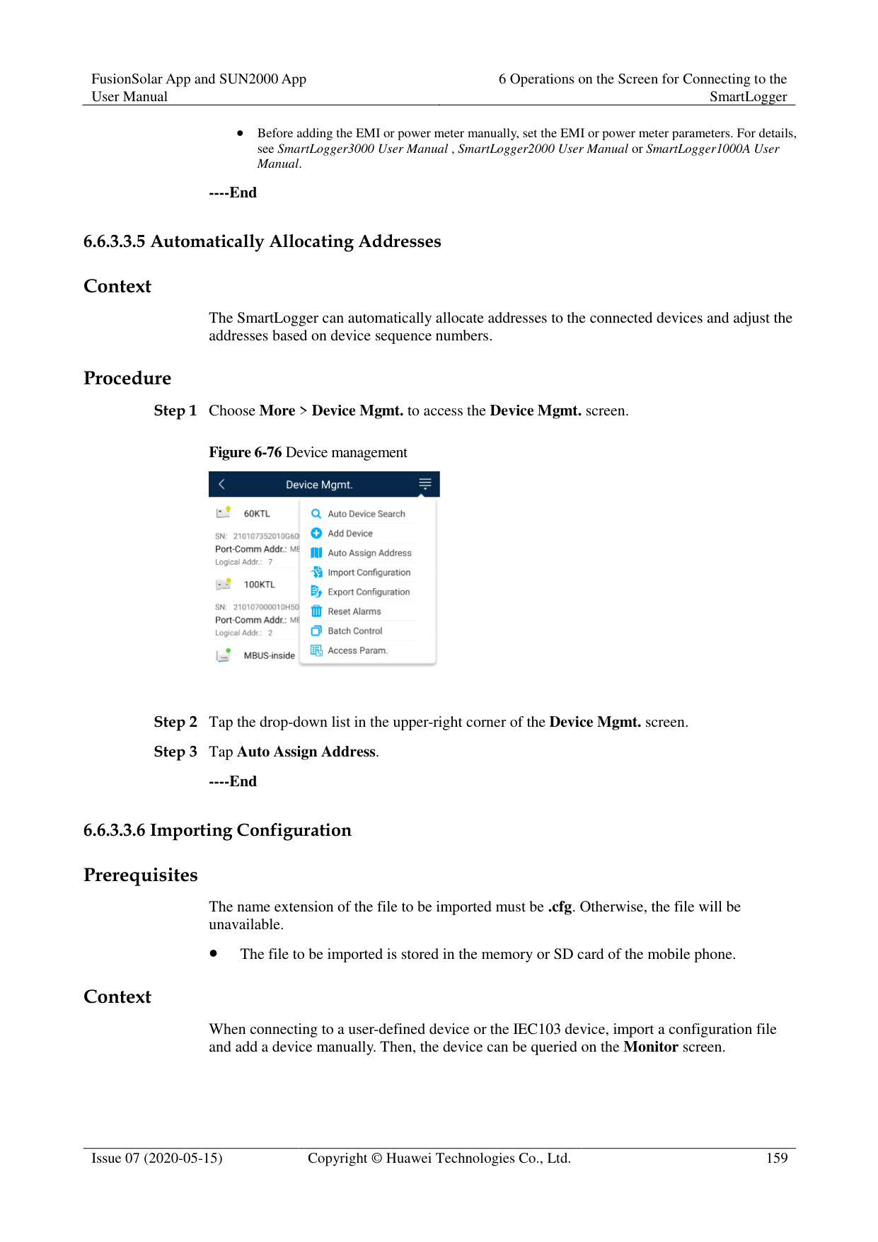


The password must meet the following requirements:
Contains 6–20 characters.
Contains at least two of the following types: lowercase letters, uppercase letters, and digits.
----End
######## Context
After the system resets, the SmartLogger restarts. Procedure


----End
######## Context
Clear data if the SmartLogger is relocated and its historical data needs to be deleted.

After you perform Clear Data, electric energy yield data, performance data, and alarms are cleared from the SmartLogger.
After you perform Clear Data, the devices connected to the SmartLogger are not removed. If the original device will no longer connect to the SmartLogger, remove the device.
If you perform Clear Data on the SmartLogger, you also have to perform Reset Alarms on the NMS. Otherwise, the alarm information collected by the NMS and SmartLogger will be different.
######## Procedure


----End
######## Prerequisites
A USB flash drive has been inserted into the USB port on the SmartLogger. Context
Generating the local maintenance script is used to set SmartLogger commands and save the script file in the USB flash drive. The SmartLogger executes the local script file in the USB flash drive to export SmartLogger logs, export or import all files, upgrade application software, and upgrade BSP.
######## Procedure
########### Step 1 Choose More > System Maintenance > Generate local maint. Script to access the screen
for generating the script.


Step 2 Select operations as required and tap Generate local maint. Script to save the generated
local maintenance script file in the USB flash drive.
----End
######## Follow-up Procedure
You can also set SmartLogger commands without logging in to the app. For details, see 8.3.2 SmartLogger Maintenance Script.
######## 6.6.3.2.5 Restoring Factory SettingsContext

Perform this operation with caution because all configured parameters except the current date, time, baud rate, and address will be restored to their factory default values. This operation will not affect operating information, alarm records, or system logs.
######## Procedure

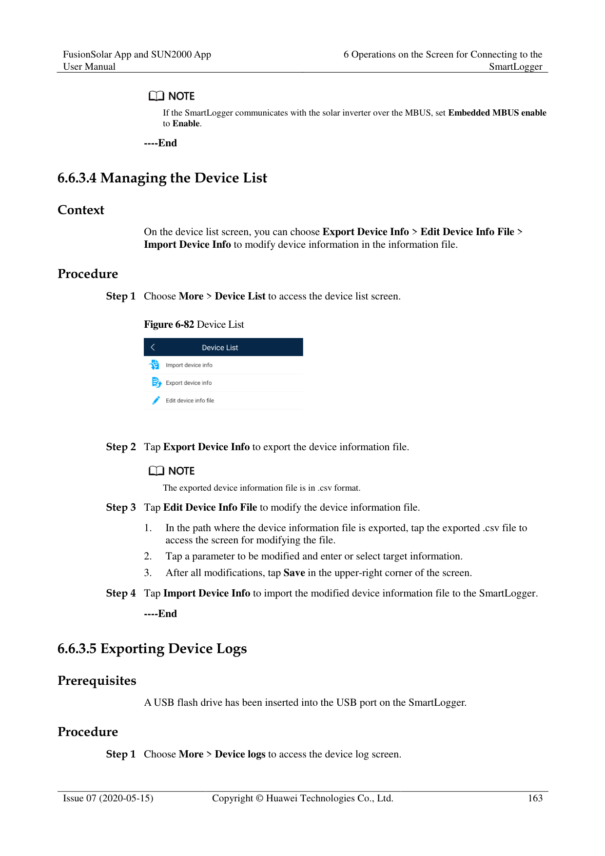
########### ----End
######## 6.6.3.3.1 Changing a Device Name Procedure
Step 1 Choose More > Device Mgmt. to access the Device Mgmt. screen. Step 2 Tap a device name to change it.
Figure 6-72 Changing a device name


The name of the SmartLogger cannot be changed.
######## ----End 6.6.3.3.2 Deleting Devices Procedure
Step 1 Choose More > Device Mgmt. to access the Device Mgmt. screen. Step 2 Hold down a device name, select the devices to be deleted, and tap Batch delete to delete
them.
Figure 6-73 Deleting devices


Deleted devices are not displayed on the Monitor screen.
######## ----End 6.6.3.3.3 Automatically Searching for Devices Context
The SmartLogger can automatically detect and connect to devices. The EMI, power meter, slave SmartLogger, and third-party devices cannot be automatically detected. You need to add them manually. For details, see 6.5.3.3.4 Manually Adding a Device.
######## Procedure
Step 1 Choose More > Device Mgmt. to access the Device Mgmt. screen.
Figure 6-74 Device management

Step 2 Tap the drop-down list in the upper-right corner of the Device Mgmt. screen. Step 3 Automatically searching for devices
######## ----End 6.6.3.3.4 Manually Adding a Device Context
The EMI, power meter, slave SmartLogger, and third-party devices cannot be automatically detected. You need to add them manually.

######## Procedure
########### Step 1 Choose More > Device Mgmt. to access the Device Mgmt. screen.
Figure 6-75 Device management

Step 2 Tap the drop-down list in the upper-right corner of the Device Mgmt. screen. Step 3 Tap Add Device and set device parameters.

Comm. Protocol is set to Modbus RTU by default. If you need to modify it, refer to 6.5.2.5 Setting RS485 Parameters.
Before adding the EMI or power meter manually, set the EMI or power meter parameters. For details, see SmartLogger3000 User Manual , SmartLogger2000 User Manual or SmartLogger1000A User Manual.
######## ----End 6.6.3.3.5 Automatically Allocating Addresses Context
The SmartLogger can automatically allocate addresses to the connected devices and adjust the addresses based on device sequence numbers.
######## Procedure
########### Step 1 Choose More > Device Mgmt. to access the Device Mgmt. screen.
Figure 6-76 Device management
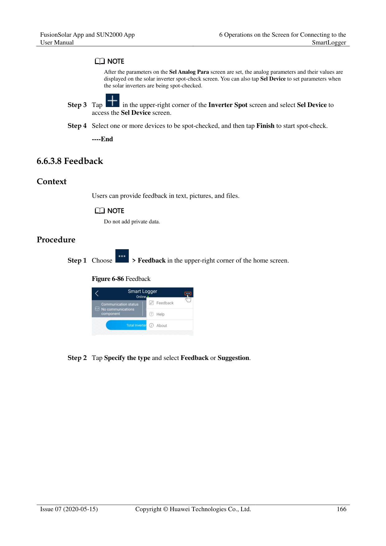

Step 2 Tap the drop-down list in the upper-right corner of the Device Mgmt. screen. Step 3 Tap Auto Assign Address.
######## ----End 6.6.3.3.6 Importing Configuration Prerequisites
The name extension of the file to be imported must be .cfg. Otherwise, the file will be unavailable.
The file to be imported is stored in the memory or SD card of the mobile phone. Context
When connecting to a user-defined device or the IEC103 device, import a configuration file and add a device manually. Then, the device can be queried on the Monitor screen.
######## Procedure
########### Step 1 Choose More > Device Mgmt. to access the Device Mgmt. screen.
Figure 6-77 Device management

Step 2 Tap the drop-down list in the upper-right corner of the Device Mgmt. screen. Step 3 Tap Import Config to import the .cfg file.
######## ----End 6.6.3.3.7 Exporting Configuration Context
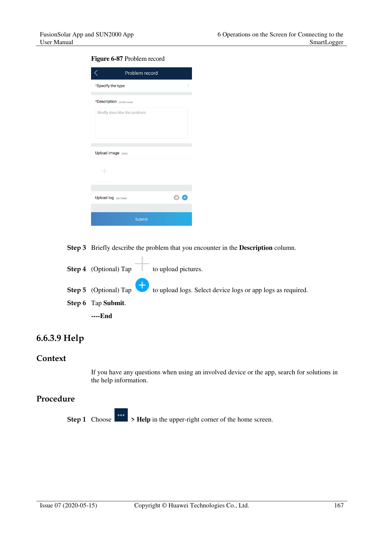
After connecting to a third-party device, you can choose Export Config to view its configuration file.
######## Procedure
########### Step 1 Choose More > Device Mgmt. to access the Device Mgmt. screen.
Figure 6-78 Device management

Step 2 Tap the drop-down list in the upper-right corner of the Device Mgmt. screen. Step 3 Tap Export Config.
######## ----End 6.6.3.3.8 Resetting Alarms Context
If you reset alarms, all the active and historical alarms of the selected device are deleted and the SmartLogger starts to collect new alarm data.
If data is deleted for a solar inverter, you must reset alarms on the SmartLogger and the NMS; otherwise, the SmartLogger cannot collect new alarm data from the solar inverter.
If alarms are reset on the SmartLogger, you must reset alarms on the NMS; otherwise, the NMS cannot obtain the new alarm data collected by the SmartLogger from the solar inverter.
######## Procedure
########### Step 1 Choose More > Device Mgmt. to access the Device Mgmt. screen.
Figure 6-79 Device management
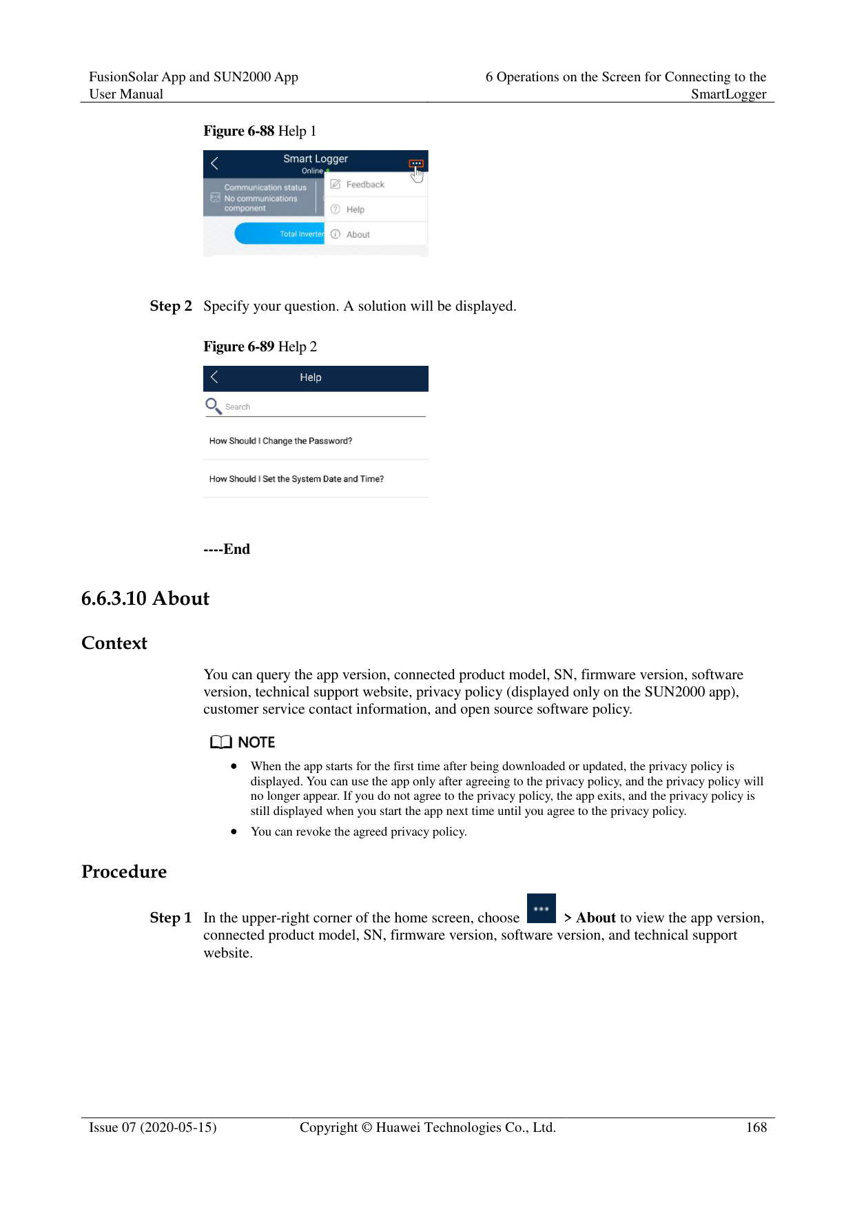

Step 2 Tap the drop-down list in the upper-right corner of the Device Mgmt. screen. Step 3 Tap Reset Alarms and select a device on the Reset Alarms screen. Step 4 Tap OK.
######## ----End 6.6.3.3.9 Starting, Shutting down, and Resetting Solar Inverters in Batches Context
Batch control operations allow the SmartLogger to start, shut down, and reset the connected solar inverters in batches. The solar inverters automatically restart after reset.
######## Procedure
Step 1 Choose More > Device Mgmt. to access the Device Mgmt. screen.
Figure 6-80 Device management

Step 2 Tap the drop-down list in the upper-right corner of the Device Mgmt. screen. Step 3 Tap Batch Control. Step 4 Tap Batch startup, Batch shutdown, or Batch reset, enter the app login password, and tap
OK.
######## ----End 6.6.3.3.10 Setting Access Parameter Context
Before connecting a device to the SmartLogger, configure access parameters correctly. Procedure
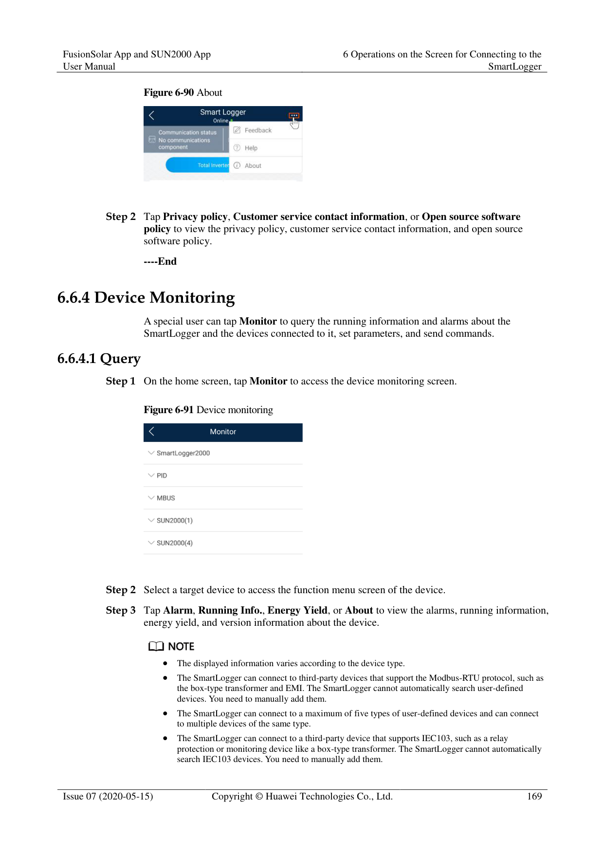
########### Step 1 Choose More > Device Mgmt. to access the Device Mgmt. screen.
Figure 6-81 Device management

Step 2 Tap the drop-down list in the upper-right corner of the Device Mgmt. screen. Step 3 Tap Access Param. to access the settings screen.

If the SmartLogger communicates with the solar inverter over the MBUS, set Embedded MBUS enable to Enable.
----End
####### 6.6.3.4 Managing the Device List
Context
On the device list screen, you can choose Export Device Info > Edit Device Info File > Import Device Info to modify device information in the information file.
Procedure
Step 1 Choose More > Device List to access the device list screen.
Figure 6-82 Device List
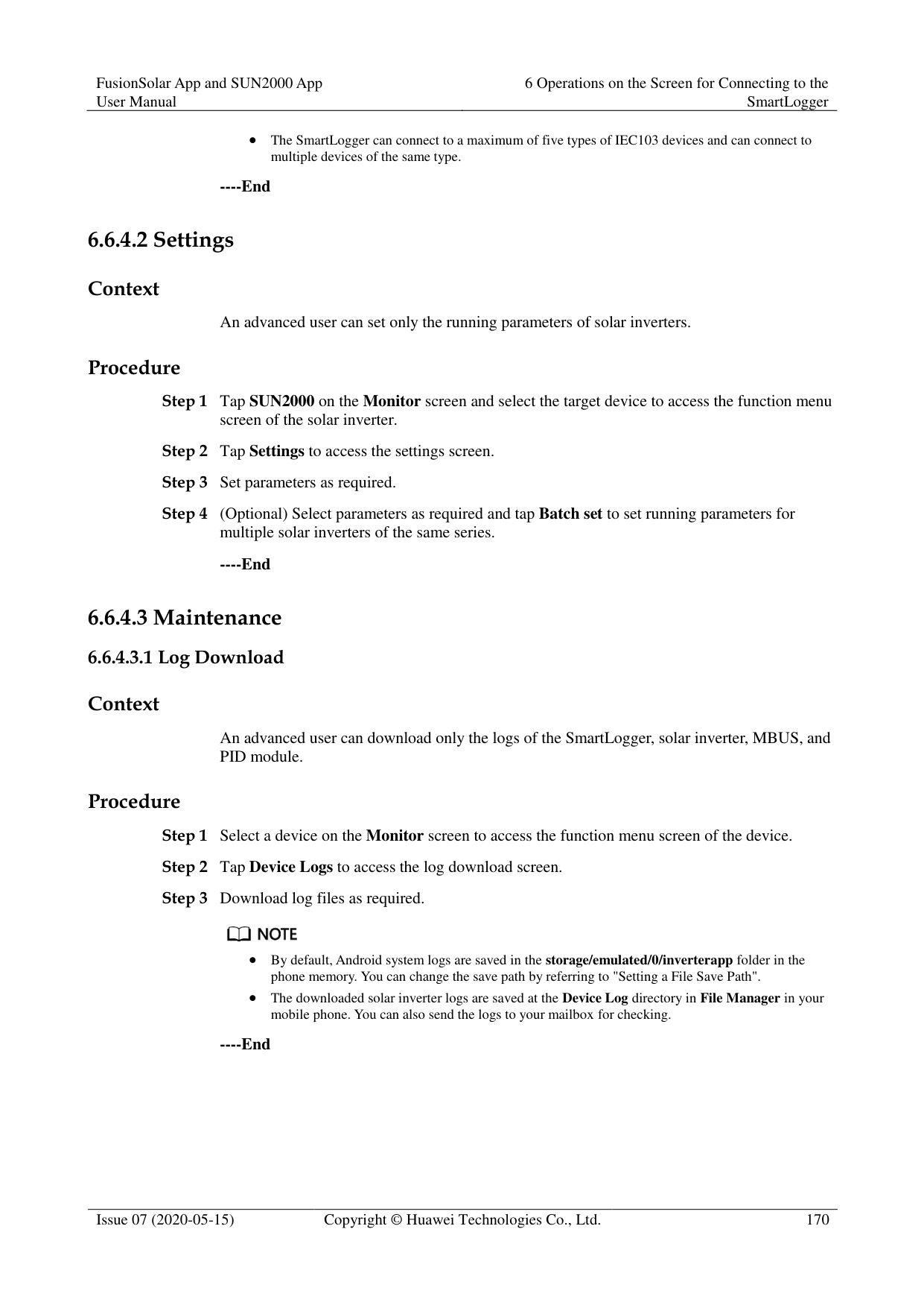

Step 2 Tap Export Device Info to export the device information file.

The exported device information file is in .csv format. Step 3 Tap Edit Device Info File to modify the device information file.
Step 4 Tap Import Device Info to import the modified device information file to the SmartLogger.
----End
####### 6.6.3.5 Exporting Device Logs
######## Prerequisites
A USB flash drive has been inserted into the USB port on the SmartLogger. Procedure
Step 1 Choose More > Device logs to access the device log screen.

Step 2 Tap in the upper-right corner of the screen, select a device whose logs are to be
exported, and tap Next.
Figure 6-83 Exporting device logs

Step 3 Select the types of logs to be exported and tap OK to start exporting device logs.

The downloaded device logs are saved at the storage path of the USB flash drive.
----End
####### 6.6.3.6 Device Upgrade
######## Prerequisites
Obtain the upgrade package from your supplier or Huawei engineers.
Insert the USB flash drive where the upgrade package is saved into the USB port on the
######## SmartLogger. Procedure
Step 1 Choose More > Upgrade to access the device upgrade screen.
Figure 6-84 Device upgrade


Step 2 Tap in the upper-right corner, select a single device or devices of the same type, and
tap Next. Step 3 Select the upgrade package and tap Next. Step 4 Confirm the upgrade package and the device to be upgraded, and tap Finish to start upgrading
the device.
----End
####### 6.6.3.7 Spot-Checking Solar Inverters
######## Context
You can perform spot-check for the solar inverter whose Grid Code is Japan standard. Procedure
Step 1 Choose More > Inverter Spot to access the solar inverter spot-check screen.
Figure 6-85 Inverter spot


Step 2 (Optional) Tap in the upper-right corner of the Inverter Spot screen, select Sel Ana Para, and tap Finish to set analog parameters.

After the parameters on the Sel Analog Para screen are set, the analog parameters and their values are displayed on the solar inverter spot-check screen. You can also tap Sel Device to set parameters when the solar inverters are being spot-checked.

Step 3 Tap in the upper-right corner of the Inverter Spot screen and select Sel Device to
access the Sel Device screen.
Step 4 Select one or more devices to be spot-checked, and then tap Finish to start spot-check.
----End
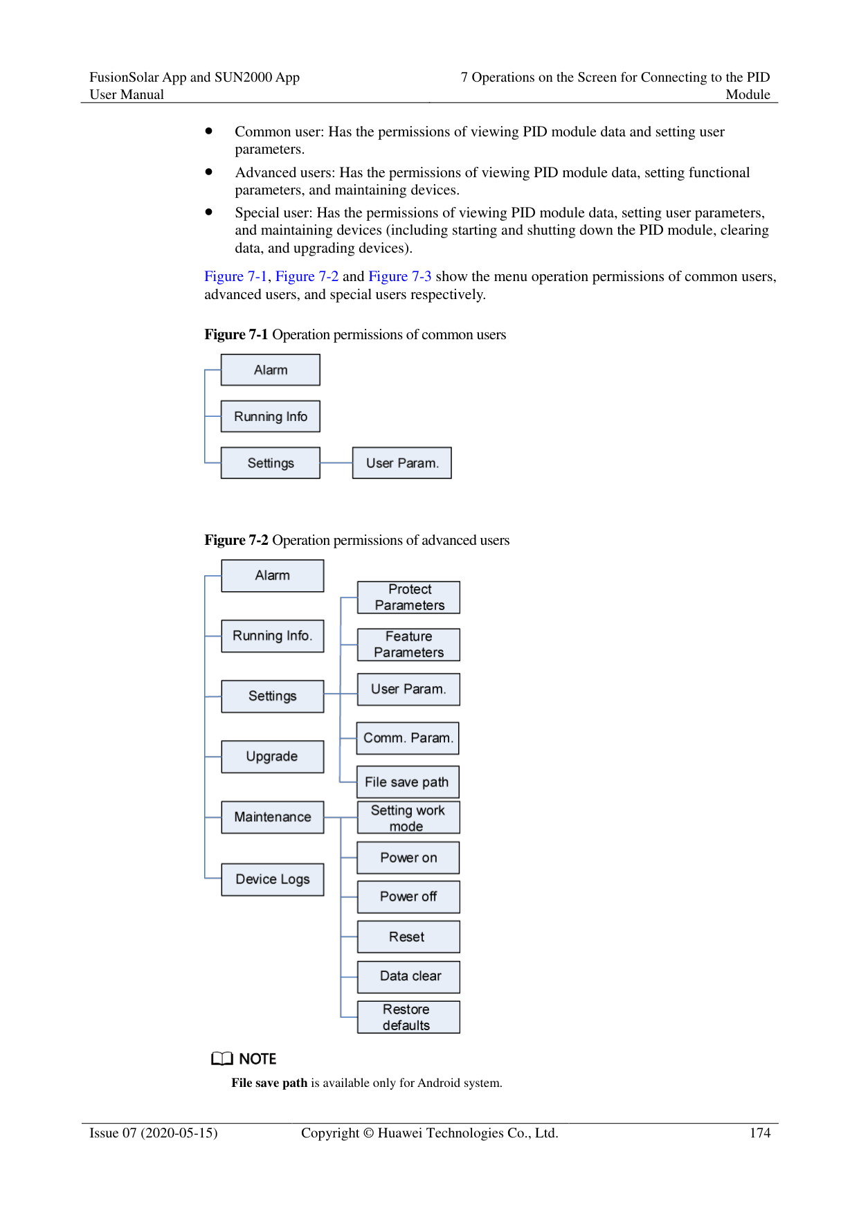
####### 6.6.3.8 Feedback
######## Context
Users can provide feedback in text, pictures, and files.

Do not add private data. Procedure

Figure 6-86 Feedback

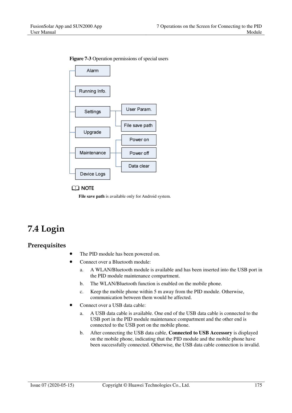


----End
####### 6.6.3.9 Help
######## Context
If you have any questions when using an involved device or the app, search for solutions in the help information.
######## Procedure

Step 1 Choose > Help in the upper-right corner of the home screen.
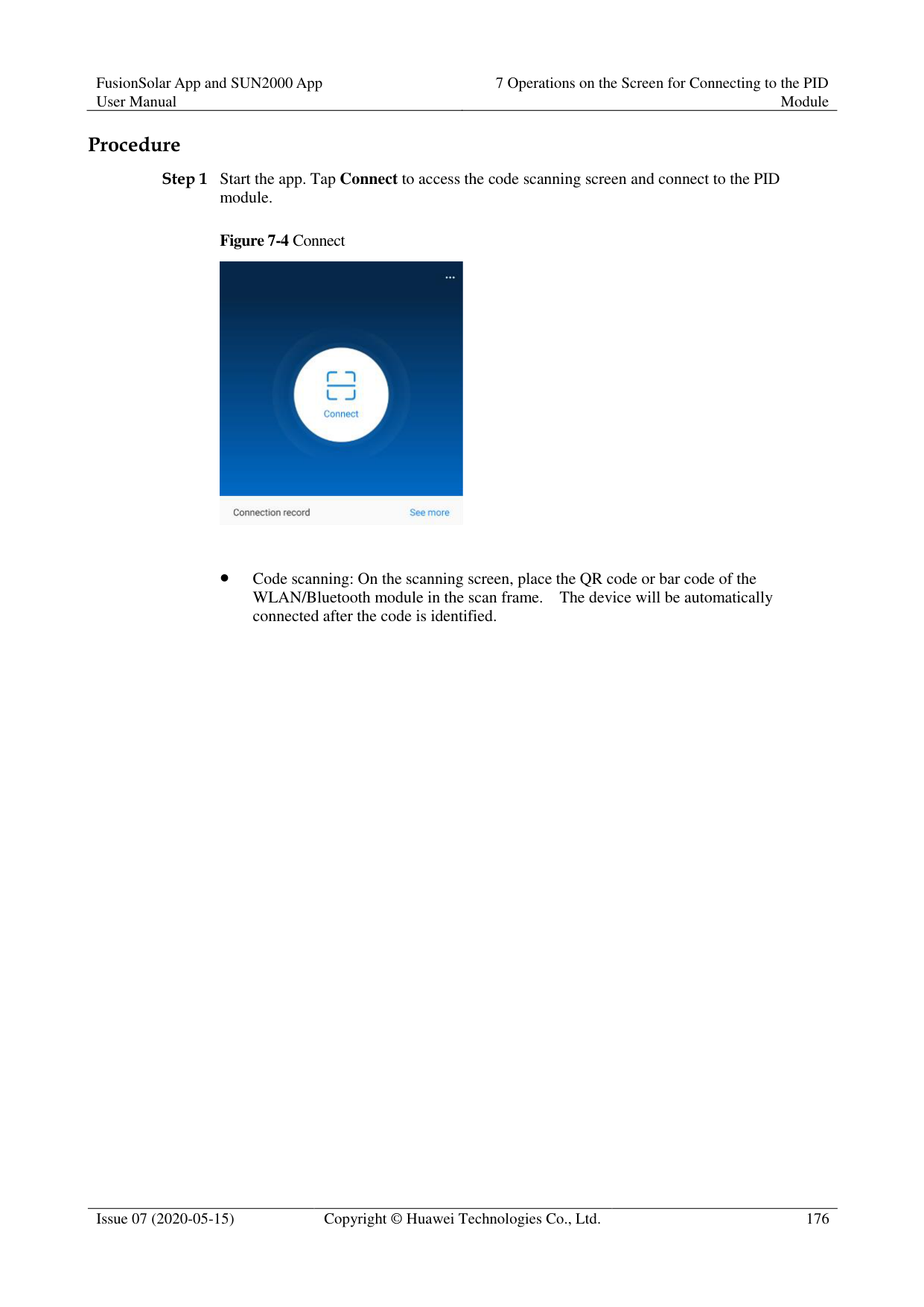
########### Figure 6-88 Help 1

Step 2 Specify your question. A solution will be displayed.
Figure 6-89 Help 2

----End
####### 6.6.3.10 About
######## Context
You can query the app version, connected product model, SN, firmware version, software version, technical support website, privacy policy (displayed only on the SUN2000 app), customer service contact information, and open source software policy.

When the app starts for the first time after being downloaded or updated, the privacy policy is displayed. You can use the app only after agreeing to the privacy policy, and the privacy policy will no longer appear. If you do not agree to the privacy policy, the app exits, and the privacy policy is still displayed when you start the app next time until you agree to the privacy policy.
You can revoke the agreed privacy policy. Procedure

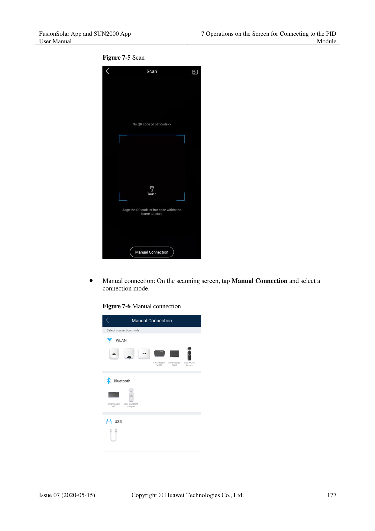
Step 1 In the upper-right corner of the home screen, choose > About to view the app version, connected product model, SN, firmware version, software version, and technical support website.
########### Figure 6-90 About

Step 2 Tap Privacy policy, Customer service contact information, or Open source software policy to view the privacy policy, customer service contact information, and open source software policy.
----End
##### 6.6.4 Device Monitoring
A special user can tap Monitor to query the running information and alarms about the SmartLogger and the devices connected to it, set parameters, and send commands.
Figure 6-91 Device monitoring

Step 2 Select a target device to access the function menu screen of the device. Step 3 Tap Alarm, Running Info., Energy Yield, or About to view the alarms, running information,
energy yield, and version information about the device.
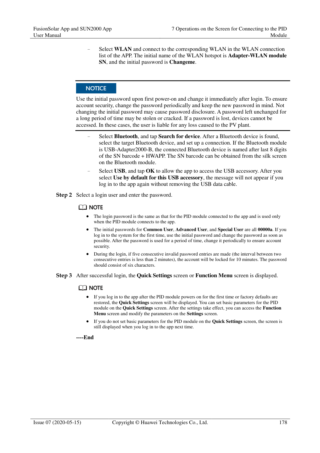

The displayed information varies according to the device type.
The SmartLogger can connect to third-party devices that support the Modbus-RTU protocol, such as the box-type transformer and EMI. The SmartLogger cannot automatically search user-defined devices. You need to manually add them.
The SmartLogger can connect to a maximum of five types of user-defined devices and can connect to multiple devices of the same type.
The SmartLogger can connect to a third-party device that supports IEC103, such as a relay protection or monitoring device like a box-type transformer. The SmartLogger cannot automatically search IEC103 devices. You need to manually add them.
The SmartLogger can connect to a maximum of five types of IEC103 devices and can connect to multiple devices of the same type.
----End
####### 6.6.4.2 Settings
Context
An advanced user can set only the running parameters of solar inverters. Procedure
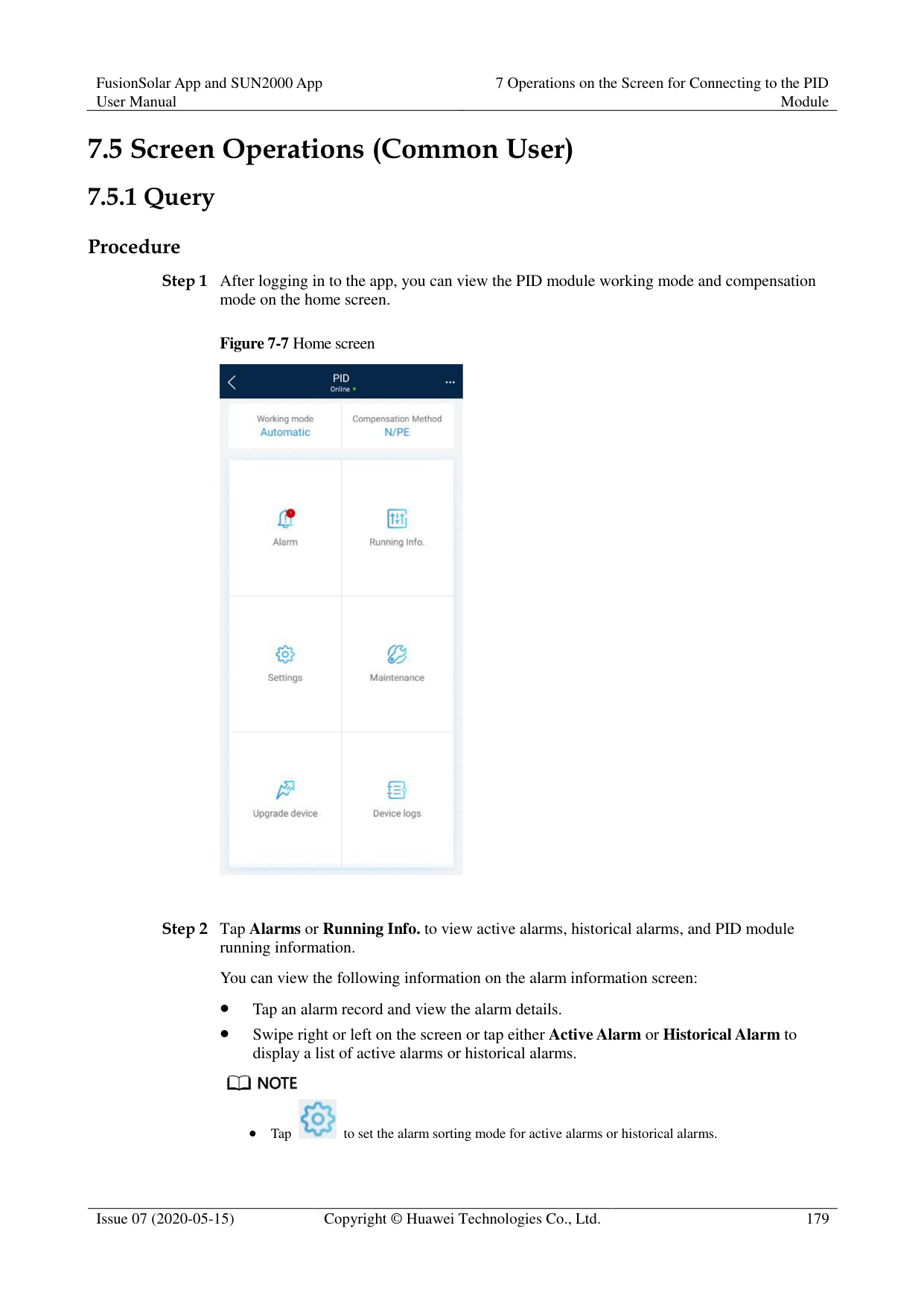
----End
####### 6.6.4.3 Maintenance
######## Context
An advanced user can download only the logs of the SmartLogger, solar inverter, MBUS, and PID module.
######## Procedure

By default, Android system logs are saved in the storage/emulated/0/inverterapp folder in the phone memory. You can change the save path by referring to "Setting a File Save Path".
The downloaded solar inverter logs are saved at the Device Log directory in File Manager in your mobile phone. You can also send the logs to your mailbox for checking.
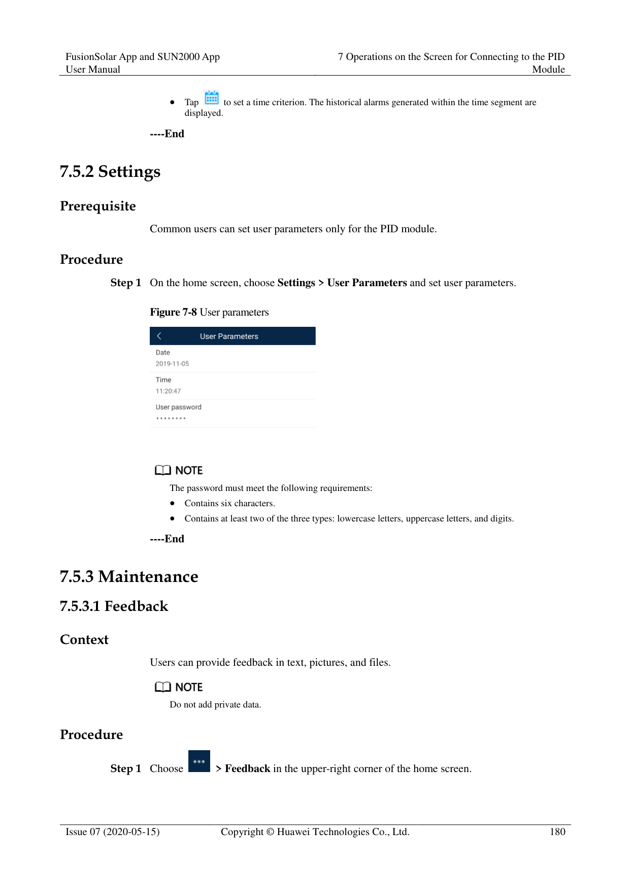
########### ----End
######## 6.6.4.3.2 Solar Inverter MaintenanceProcedure


Tap Performance Data to view the performance data curve of the solar inverter.
########### ----End
7 Operations on the Screen for Connecting
to the PID Module

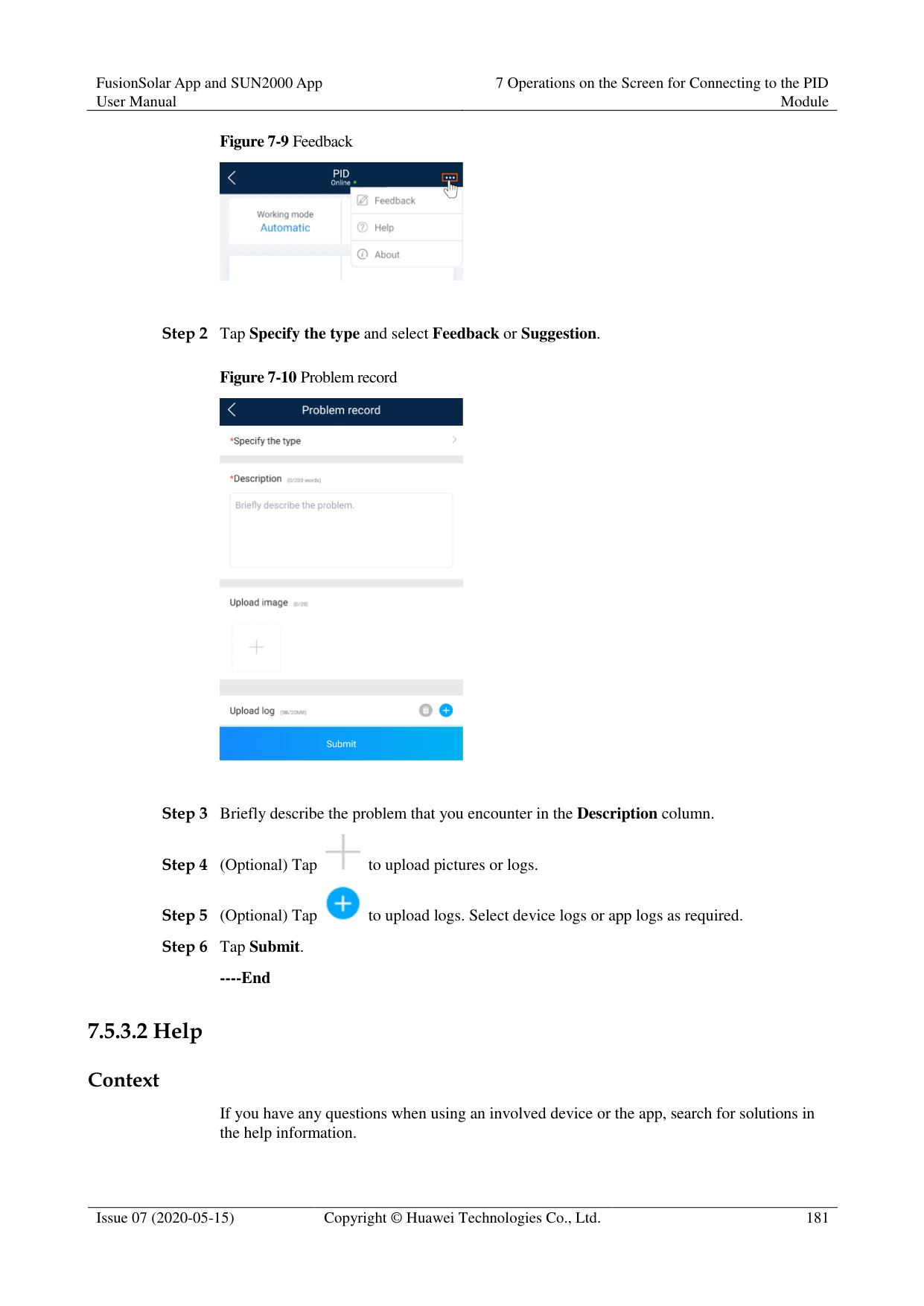
The app screenshots provided in this chapter correspond to the SUN2000 app 3.2.00.005 version. The data on the screenshots is for reference only.
#### 7.1 PID Module
######## Connection Modes
After the SmartPID2000 (PID module for short) is powered on, it can connect to the app over a WLAN module, a Bluetooth module, or a USB data cable.
|PID Module|PID Module Version
|App Version|Connection Mode|Connection Mode| |---|---|---|---|---| |PID Module|PID Module Version
|App Version|USB-Adapter2000
-C WLAN Module/USB-Ad apter2000-B Bluetooth Module
|USB Data Cable| |SmartPID2000|SmartPID2000 V100R001C00 and later versions|3.2.00.005|Supported|Supported|
Table 7-2 Product mapping (iOS)
|PID Module
|PID Module Version
|App Version|Connection Mode|Connection Mode| |---|---|---|---|---| |PID Module
|PID Module Version
|App Version|USB-Adapter2000
-B Bluetooth Module
|USB Data Cable| |SmartPID2000|SmartPID2000 V100R001C00 and later versions|2.2.00.050|Supported|Not supported|
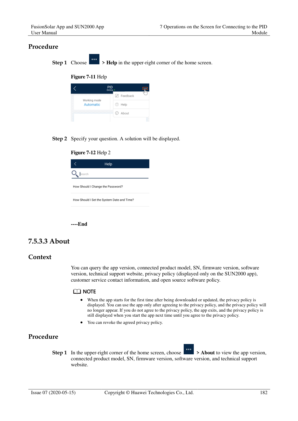
#### 7.2 Required Accessories
Mobile Phone
Mobile phone operating system: Android 4.4 or later. Recommended phone brands: Huawei and Samsung. The mobile phone supports the access to the Internet over a web browser.
WLAN/Bluetooth supported. WLAN/Bluetooth Module
Purchase a WLAN/Bluetooth module that matches the PID module. A WLAN/Bluetooth module purchased from any other source may not support communication between the app module and the PID module.
Table 7-3 WLAN/Bluetooth module model
|Model|Module|Item Code|Purchased From| |---|---|---|---| |USB-Adapter2000C|WLAN module|02312MCK|Can be purchased from Huawei| |USB-Adapter2000B|Bluetooth module|02311NEA|Can be purchased from Huawei| |BF4030|Bluetooth module|06080358|Can be purchased from Huawei|
USB Data Cable
The USB data cable is delivered with the phone.
#### 7.3 User Operation Permissions

The user accounts that can log in to the app are classified into common users, special users, and advanced users based on the responsibilities of PV plant operation personnel.
Common user: Has the permissions of viewing PID module data and setting user parameters.
Advanced users: Has the permissions of viewing PID module data, setting functional parameters, and maintaining devices.
Special user: Has the permissions of viewing PID module data, setting user parameters, and maintaining devices (including starting and shutting down the PID module, clearing data, and upgrading devices).
Figure 7-1, Figure 7-2 and Figure 7-3 show the menu operation permissions of common users, advanced users, and special users respectively.


File save path is available only for Android system.
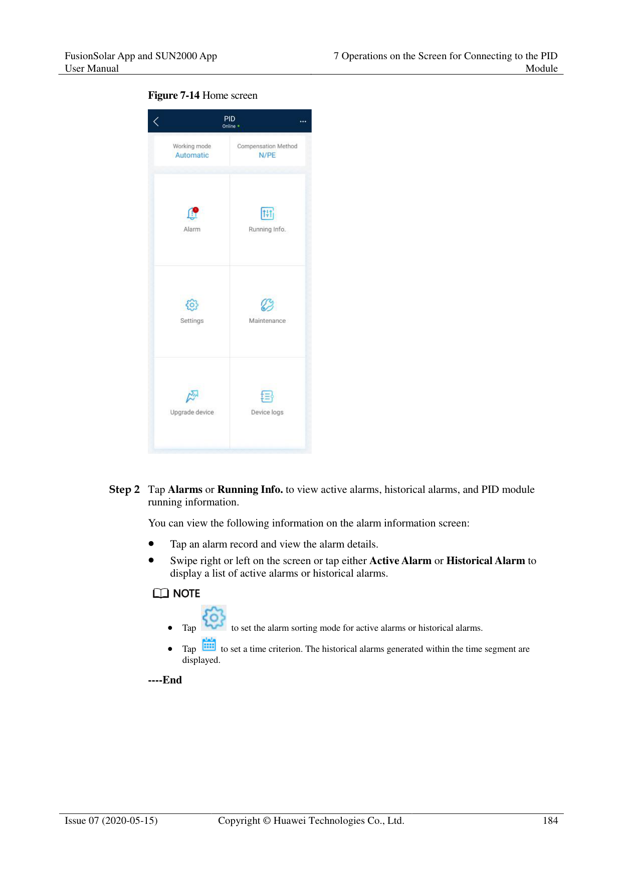


File save path is available only for Android system.
#### 7.4 Login
######## Prerequisites
The PID module has been powered on.
Connect over a Bluetooth module: a. A WLAN/Bluetooth module is available and has been inserted into the USB port in
the PID module maintenance compartment. b. The WLAN/Bluetooth function is enabled on the mobile phone. c. Keep the mobile phone within 5 m away from the PID module. Otherwise,
communication between them would be affected.
Connect over a USB data cable:
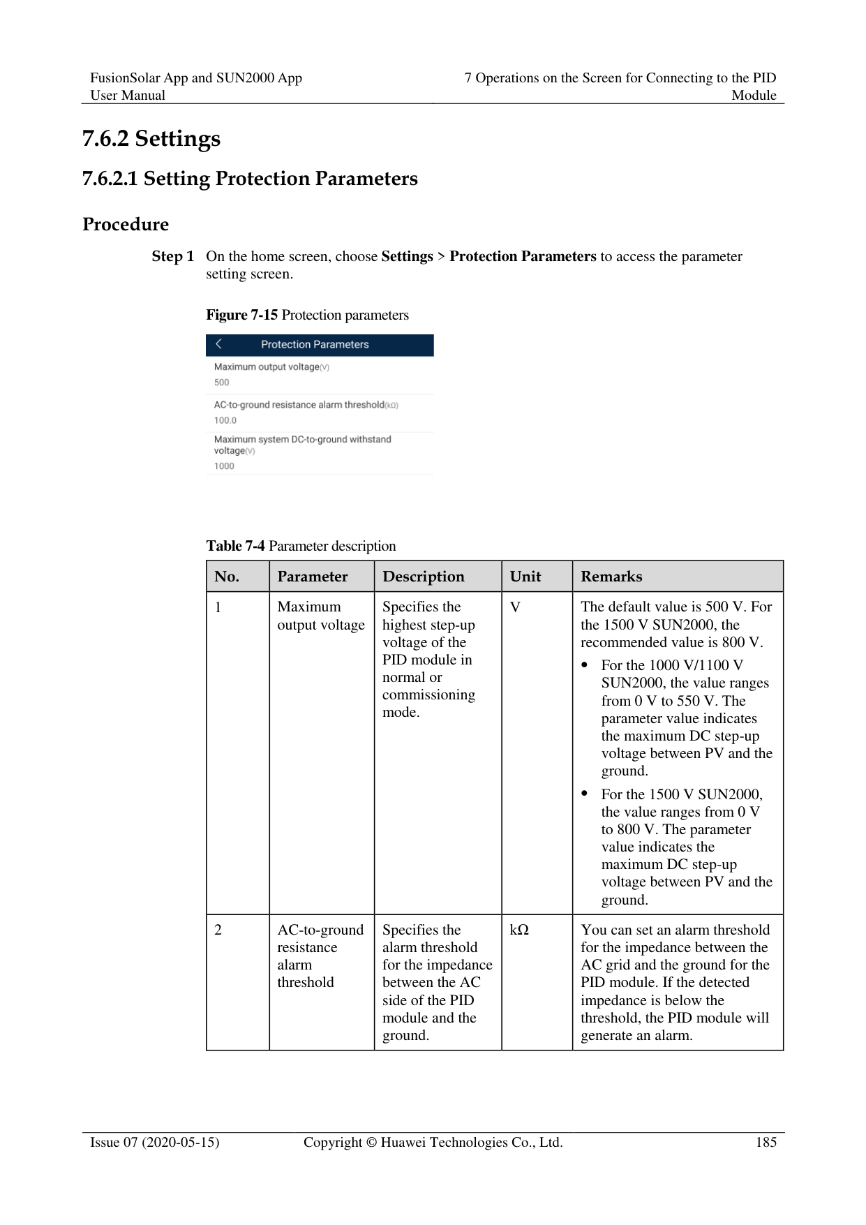
######## Procedure
########### Figure 7-4 Connect

Code scanning: On the scanning screen, place the QR code or bar code of the WLAN/Bluetooth module in the scan frame. The device will be automatically connected after the code is identified.
########### Figure 7-5 Scan

Manual connection: On the scanning screen, tap Manual Connection and select a connection mode.
Figure 7-6 Manual connection

− Select WLAN and connect to the corresponding WLAN in the WLAN connection list of the APP. The initial name of the WLAN hotspot is Adapter-WLAN module SN, and the initial password is Changeme.

Use the initial password upon first power-on and change it immediately after login. To ensure account security, change the password periodically and keep the new password in mind. Not changing the initial password may cause password disclosure. A password left unchanged for a long period of time may be stolen or cracked. If a password is lost, devices cannot be accessed. In these cases, the user is liable for any loss caused to the PV plant.
− Select Bluetooth, and tap Search for device. After a Bluetooth device is found,
select the target Bluetooth device, and set up a connection. If the Bluetooth module is USB-Adapter2000-B, the connected Bluetooth device is named after last 8 digits of the SN barcode + HWAPP. The SN barcode can be obtained from the silk screen on the Bluetooth module.
Select USB, and tap OK to allow the app to access the USB accessory. After you select Use by default for this USB accessory, the message will not appear if you log in to the app again without removing the USB data cable.

The login password is the same as that for the PID module connected to the app and is used only when the PID module connects to the app.
The initial passwords for Common User, Advanced User, and Special User are all 00000a. If you log in to the system for the first time, use the initial password and change the password as soon as possible. After the password is used for a period of time, change it periodically to ensure account security.
During the login, if five consecutive invalid password entries are made (the interval between two consecutive entries is less than 2 minutes), the account will be locked for 10 minutes. The password should consist of six characters.

If you log in to the app after the PID module powers on for the first time or factory defaults are restored, the Quick Settings screen will be displayed. You can set basic parameters for the PID module on the Quick Settings screen. After the settings take effect, you can access the Function Menu screen and modify the parameters on the Settings screen.
If you do not set basic parameters for the PID module on the Quick Settings screen, the screen is still displayed when you log in to the app next time.
########### ----End
#### 7.5 Screen Operations (Common User)
##### 7.5.1 Query
######## Procedure
Step 1 After logging in to the app, you can view the PID module working mode and compensation
mode on the home screen.
Figure 7-7 Home screen

Step 2 Tap Alarms or Running Info. to view active alarms, historical alarms, and PID module running information. You can view the following information on the alarm information screen:
Tap an alarm record and view the alarm details.
Swipe right or left on the screen or tap either Active Alarm or Historical Alarm to display a list of active alarms or historical alarms.


Tap to set the alarm sorting mode for active alarms or historical alarms.

Tap to set a time criterion. The historical alarms generated within the time segment are displayed.
----End
##### 7.5.2 Settings
Prerequisite
Common users can set user parameters only for the PID module. Procedure
Step 1 On the home screen, choose Settings > User Parameters and set user parameters.
Figure 7-8 User parameters


The password must meet the following requirements:
Contains six characters.
Contains at least two of the three types: lowercase letters, uppercase letters, and digits.
----End
##### 7.5.3 Maintenance
####### 7.5.3.1 Feedback
######## Context
Users can provide feedback in text, pictures, and files.

Do not add private data. Procedure

Figure 7-10 Problem record


----End
####### 7.5.3.2 Help
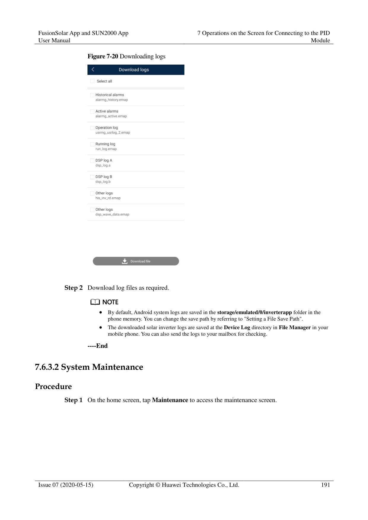
######## Context
If you have any questions when using an involved device or the app, search for solutions in the help information.
######## Procedure

Step 1 Choose > Help in the upper-right corner of the home screen.

Step 2 Specify your question. A solution will be displayed.

----End
####### 7.5.3.3 About
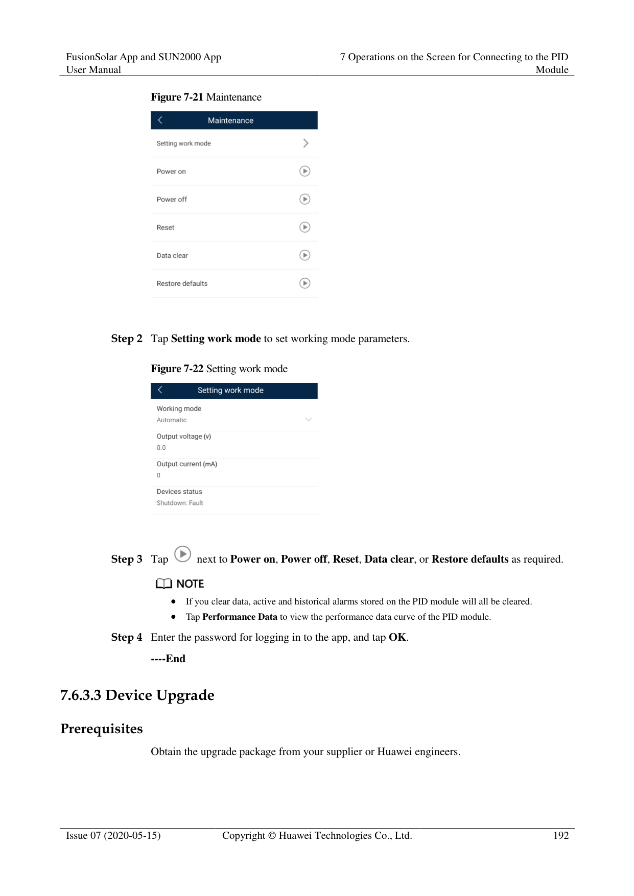
######## Context
You can query the app version, connected product model, SN, firmware version, software version, technical support website, privacy policy (displayed only on the SUN2000 app), customer service contact information, and open source software policy.

When the app starts for the first time after being downloaded or updated, the privacy policy is displayed. You can use the app only after agreeing to the privacy policy, and the privacy policy will no longer appear. If you do not agree to the privacy policy, the app exits, and the privacy policy is still displayed when you start the app next time until you agree to the privacy policy.
You can revoke the agreed privacy policy. Procedure


----End
#### 7.6 Screen Operations (Advanced User)
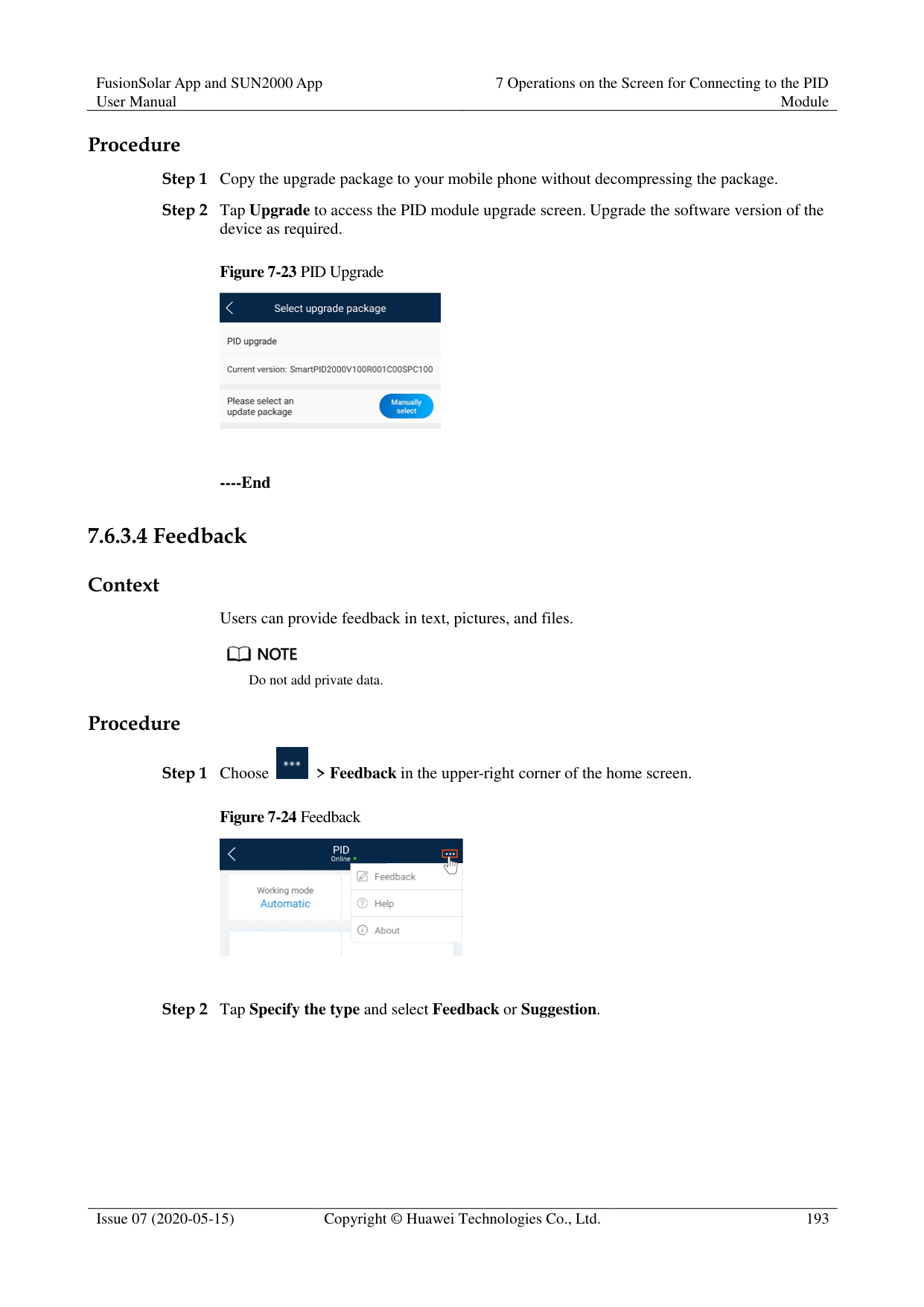
##### 7.6.1 Query
######## Procedure
Step 1 After logging in to the app, you can view the PID module working mode and compensation
mode on the home screen.
Figure 7-14 Home screen

Step 2 Tap Alarms or Running Info. to view active alarms, historical alarms, and PID module running information. You can view the following information on the alarm information screen:
Tap an alarm record and view the alarm details.
Swipe right or left on the screen or tap either Active Alarm or Historical Alarm to display a list of active alarms or historical alarms.


Tap to set the alarm sorting mode for active alarms or historical alarms.
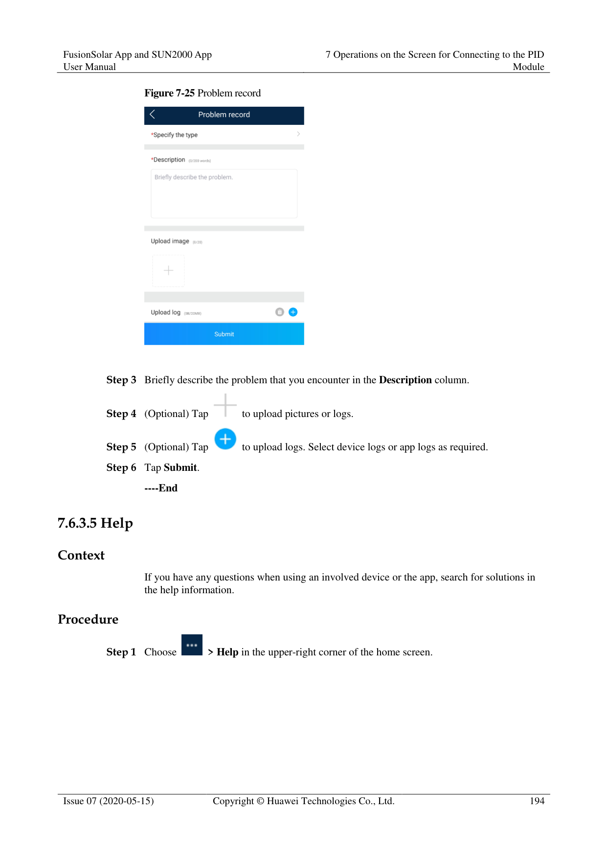

Tap to set a time criterion. The historical alarms generated within the time segment are displayed.
########### ----End
##### 7.6.2 Settings
####### 7.6.2.1 Setting Protection Parameters
######## Procedure
Step 1 On the home screen, choose Settings > Protection Parameters to access the parameter
setting screen.
Figure 7-15 Protection parameters

Table 7-4 Parameter description
|No.|Parameter|Description|Unit|Remarks| |---|---|---|---|---| |1|Maximum output voltage|Specifies the highest step-up voltage of the PID module in normal or commissioning mode.|V|The default value is 500 V. For the 1500 V SUN2000, the recommended value is 800 V.
For the 1000 V/1100 V SUN2000, the value ranges from 0 V to 550 V. The parameter value indicates the maximum DC step-up voltage between PV and the ground.
For the 1500 V SUN2000, the value ranges from 0 V to 800 V. The parameter value indicates the maximum DC step-up voltage between PV and the ground.|
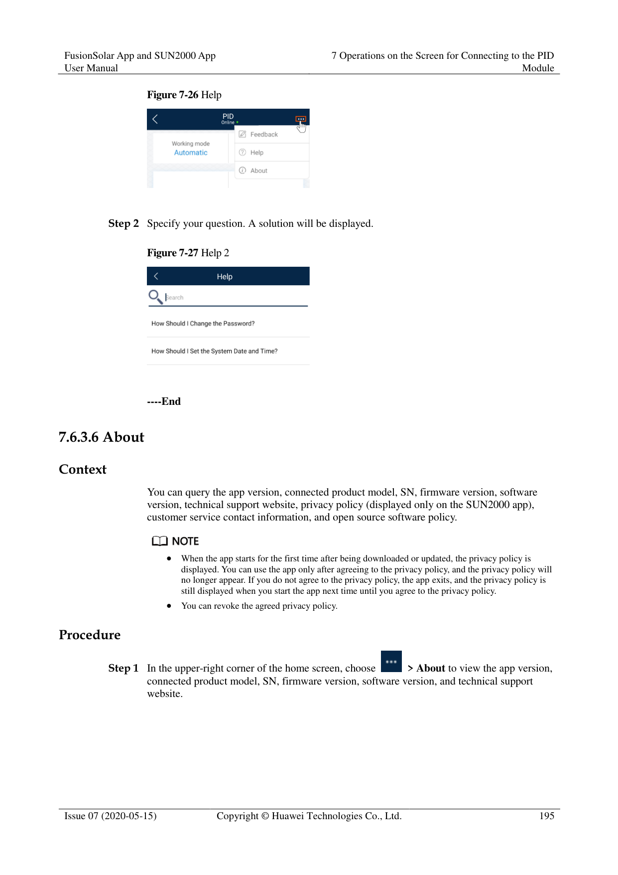
|2|AC-to-ground resistance alarm threshold|Specifies the alarm threshold for the impedance between the AC side of the PID module and the ground.|kΩ|You can set an alarm threshold for the impedance between the AC grid and the ground for the PID module. If the detected impedance is below the threshold, the PID module will generate an alarm.|
|No.|Parameter|Description|Unit|Remarks| |---|---|---|---|---| |3|Maximum system DC-to-ground withstand voltage|Specifies the voltages between the PV side and the ground and between the AC side and the ground in normal mode.|V|Specifies the lower threshold of the maximum voltage range between the solar inverter DC side (including the solar inverter, PV module, cable, SPD, and switch) and the ground.
The default value is 1000 V. For the 1500 V SUN2000, the recommended value is 1500 V.|
----End
####### 7.6.2.2 Setting Feature Parameters
######## Procedure
Step 1 On the home screen, choose Settings > Feature Parameters to access the parameter setting
screen.
Figure 7-16 Feature parameters

############ Table 7-5 Parameter description
|No.|Parameter|Description|Unit|Remarks|

|---|---|---|---|---| |1|Offset mode|Specifies the compensation mode of the PID module.|-| Select Disable if the PID module is not required.
Select N/PE if the PID module is required to use voltage output from the power grid.| |2|Compensation offset voltage|Specifies the compensation offset voltage between PV and the ground after the PID module operates stably.|V| If PV module
compensation voltage direction is set to PV– positive offset, this
parameter specifies the positive voltage between PV– and the ground.
If PV module
compensation voltage direction is set to PV+ negative offset, this
parameter specifies the negative voltage between PV+ and the ground.
NOTE If Compensation offset voltage is set to 500 V, the PID module provides the maximum output to enhance the voltage compensation effect. The output voltage amplitude of the PID module is automatically capped to ensure the safety of a PV plant. The output voltage amplitude is also related to the maximum system DC-to-ground withstand voltage and maximum output voltage.| |3|PV module compensation voltage direction|Specifies the offset direction of the PID module.|-|For the specific PV module compensation type, consult the PV module vendor. For example, P-type PV modules, HIT, CIS, thin-film PV modules, and CdTe PV modules meet the requirement for PV– positive offset.| |4|Modbus version number|Specifies the version number of the Modbus protocol of the PID module.|-|-|
|No.|Parameter|Description|Unit|Remarks| |---|---|---|---|---| |5|IMD access|Specifies whether the PID module and insulation monitor device (IMD) can operate in cycle mode.|-| Select Enable if you allow the PID module and IMD to operate in cycle mode.
Only the IMDs of mainstream suppliers such as DOLD and BENDER are supported, and the IMDs must have enabled dry contacts.
NOTICE You can set Periodic PID runtime and Periodic IMD runtime only when IMD access is set to Enable.
Select Disable if you forbid the access of IMDs.| |6|Periodic PID runtime|Specifies the operating duration of the PID module when the PID module and IMD operate in cycle mode.|min|The IMD is shut down when the PID module is operating.| |7|Periodic IMD runtime|Specifies the operating duration of the IMD when the PID module and IMD operate in cycle mode.|min|The PID module is standby when the IMD is operating.|
----End
####### 7.6.2.3 Setting User Parameters
######## Procedure
Step 1 On the home screen, choose Settings > User Parameters to access the parameter setting
screen.
Figure 7-17 User parameters
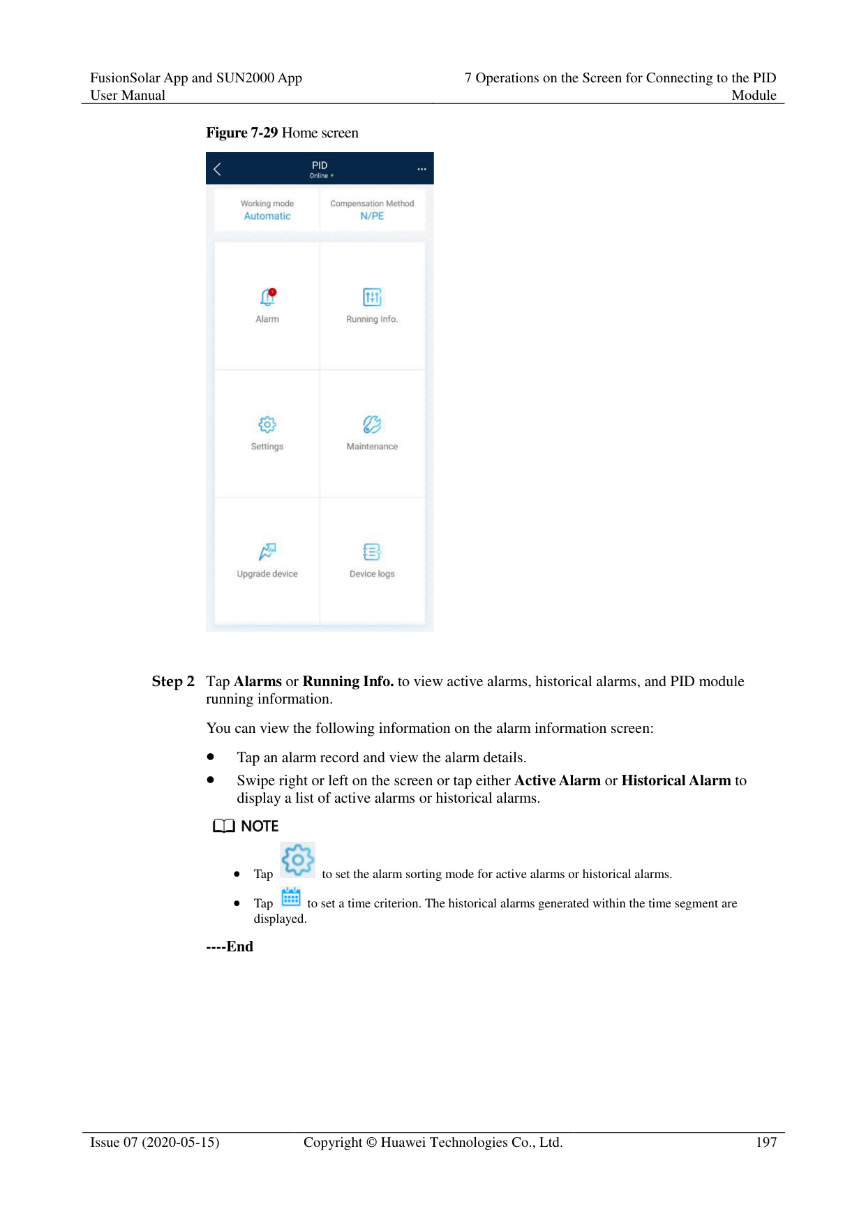


The password must meet the following requirements:
Contains six characters.
Contains at least two of the three types: lowercase letters, uppercase letters, and digits.
----End
####### 7.6.2.4 Setting Communications ParametersProcedure
Figure 7-18 Communications parameters

----End
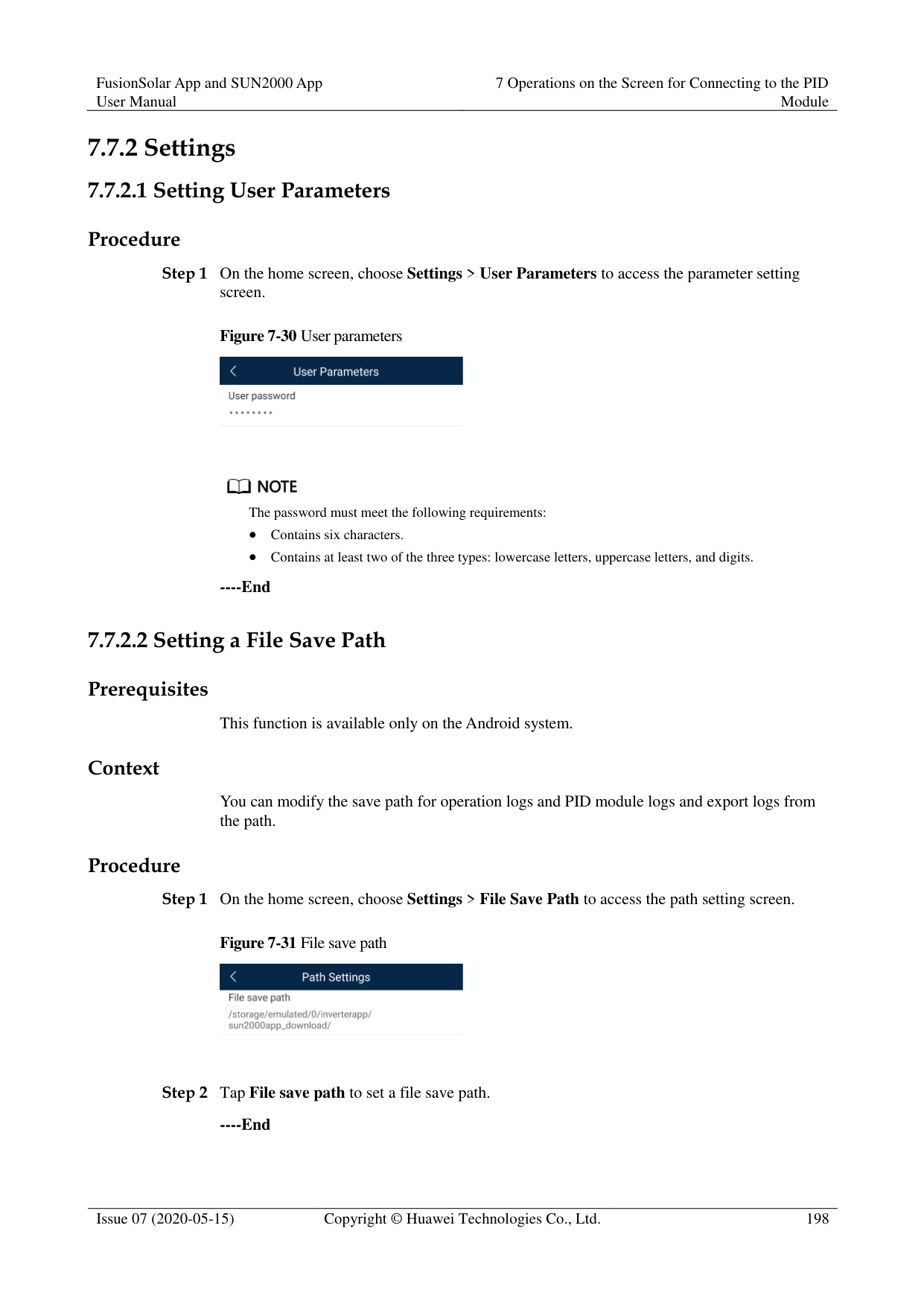
####### 7.6.2.5 Setting a File Save Path
######## Prerequisites
This function is available only on the Android system.
######## Context
You can modify the save path for operation logs and PID module logs and export logs from the path.
######## Procedure
Step 1 On the home screen, choose Settings > File Save Path to access the path setting screen.
Figure 7-19 File save path

Step 2 Tap File save path to set a file save path.
----End
##### 7.6.3 Maintenance
####### 7.6.3.1 Log Download
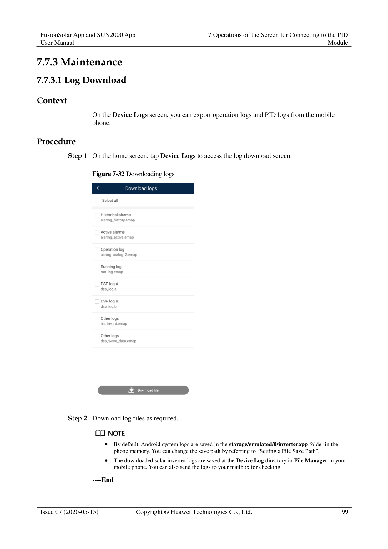
######## Context
On the Device Logs screen, you can export operation logs and PID logs from the mobile phone.
######## Procedure
Step 1 On the home screen, tap Device Logs to access the log download screen.
Figure 7-20 Downloading logs

Step 2 Download log files as required.

By default, Android system logs are saved in the storage/emulated/0/inverterapp folder in the phone memory. You can change the save path by referring to "Setting a File Save Path".
The downloaded solar inverter logs are saved at the Device Log directory in File Manager in your mobile phone. You can also send the logs to your mailbox for checking.
----End
####### 7.6.3.2 System MaintenanceProcedure
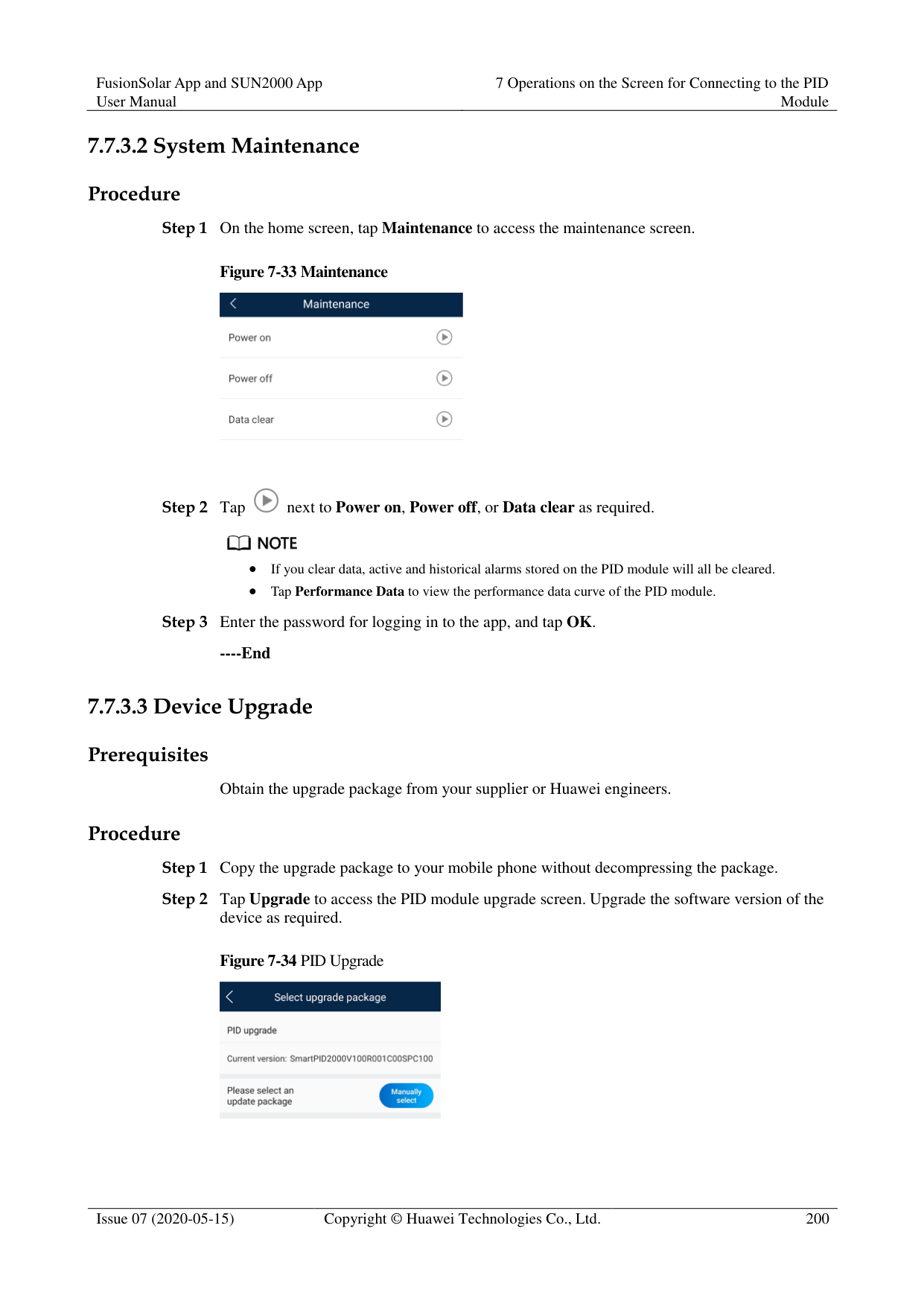
Figure 7-22 Setting work mode


If you clear data, active and historical alarms stored on the PID module will all be cleared.
Tap Performance Data to view the performance data curve of the PID module.

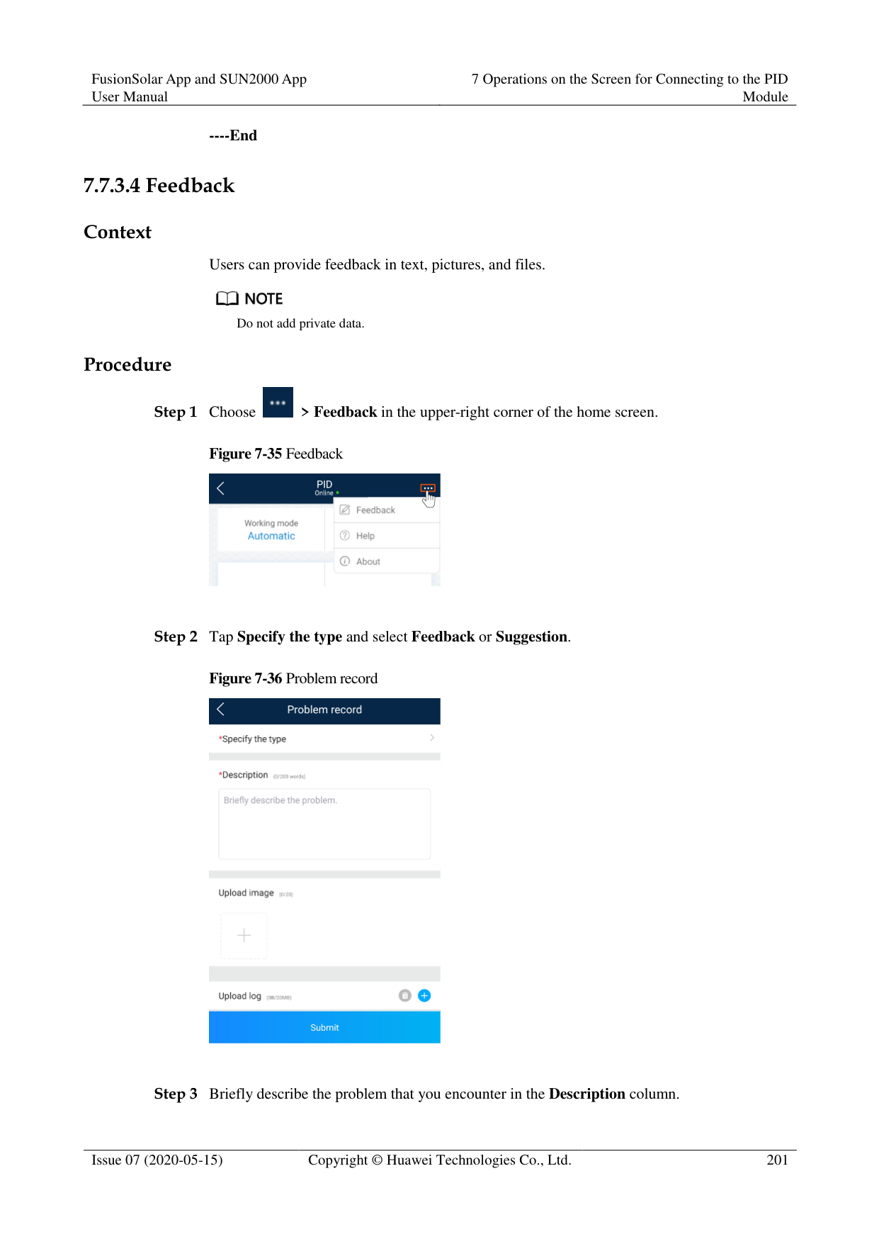
----End
####### 7.6.3.3 Device Upgrade
######## Prerequisites
Obtain the upgrade package from your supplier or Huawei engineers.
######## Procedure
Figure 7-23 PID Upgrade

----End
####### 7.6.3.4 Feedback
######## Context
Users can provide feedback in text, pictures, and files.
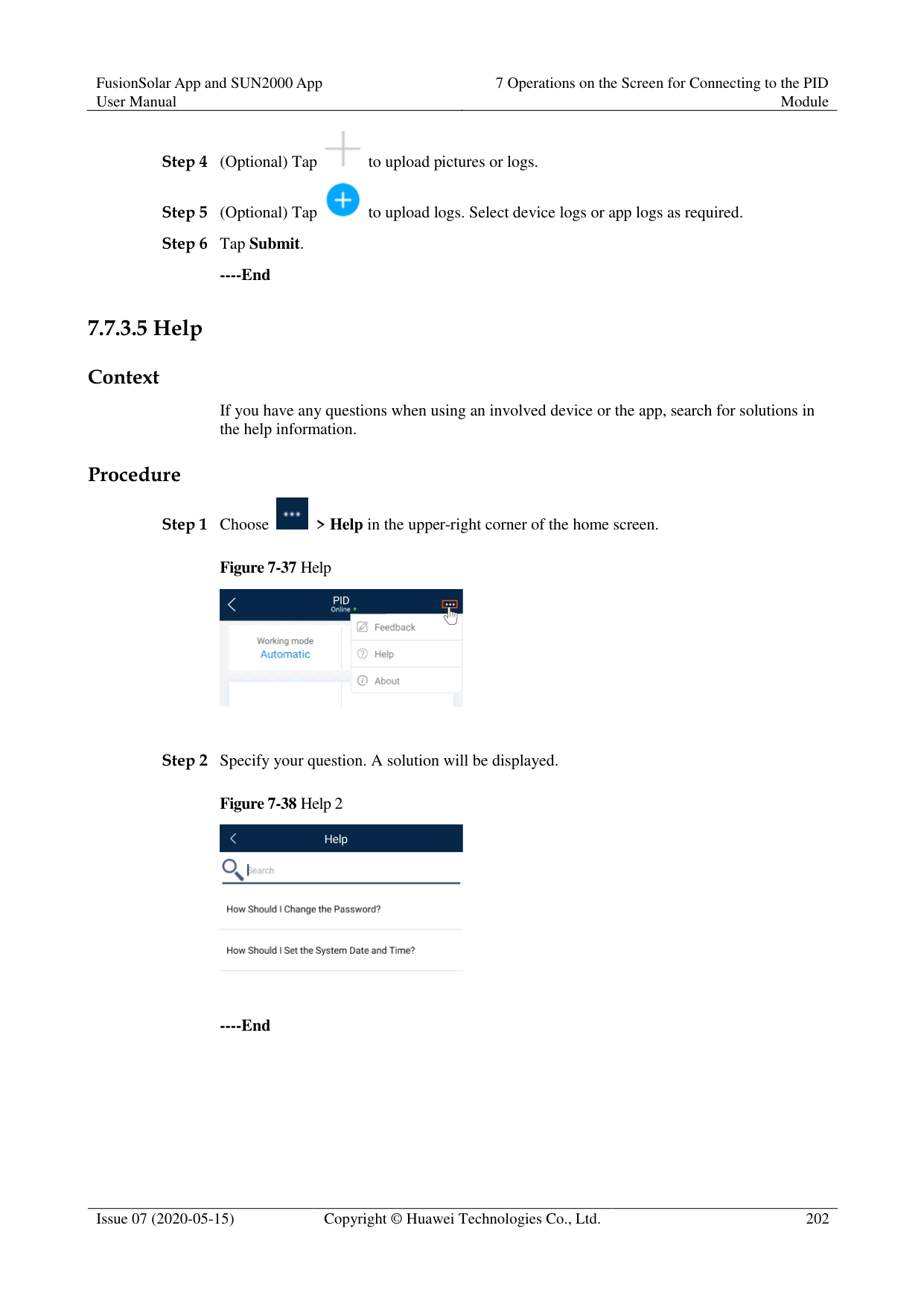

Do not add private data. Procedure

Figure 7-24 Feedback


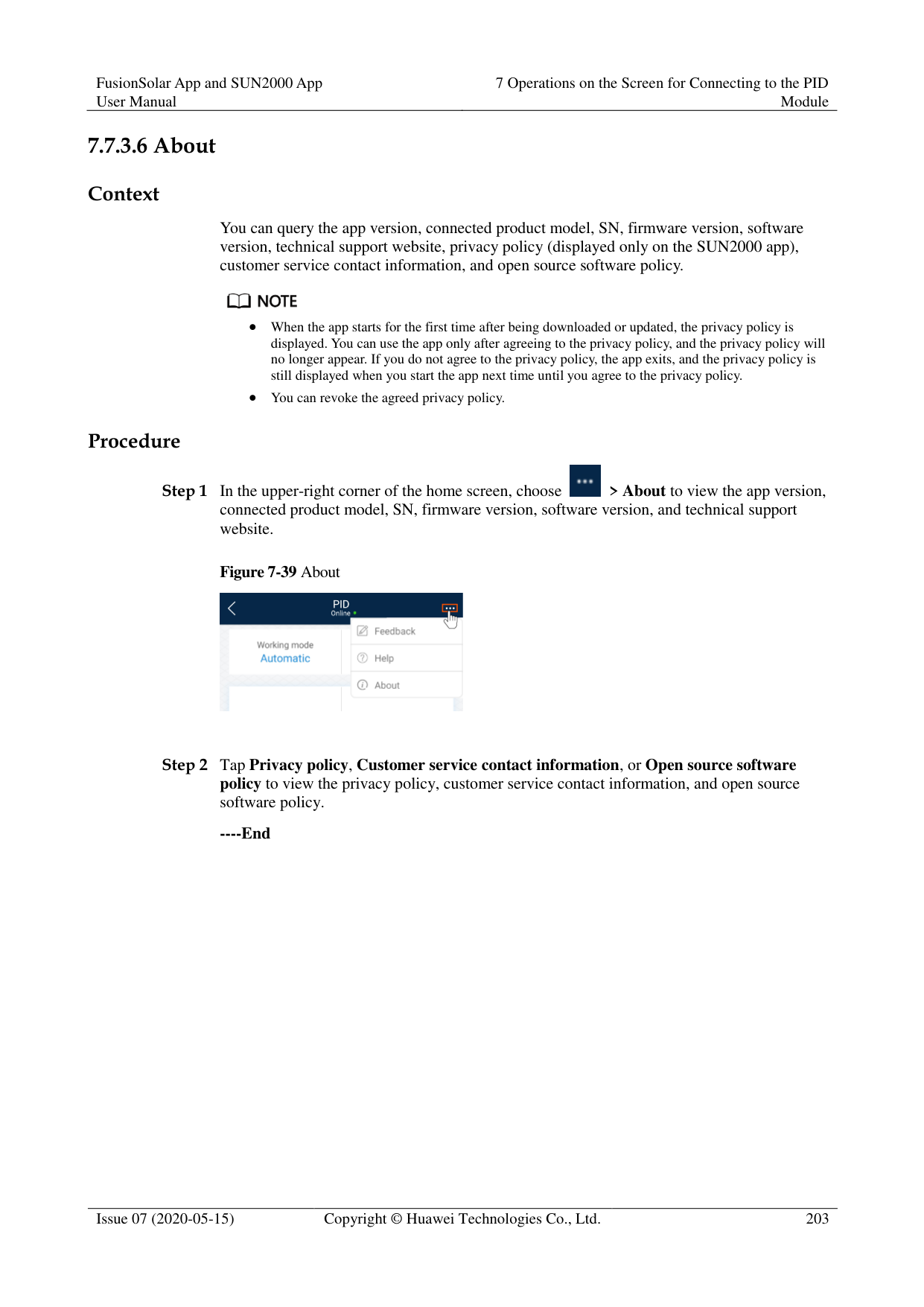

----End
####### 7.6.3.5 Help
######## Context
If you have any questions when using an involved device or the app, search for solutions in the help information.
######## Procedure

Step 1 Choose > Help in the upper-right corner of the home screen.
########### Figure 7-26 Help

Step 2 Specify your question. A solution will be displayed.
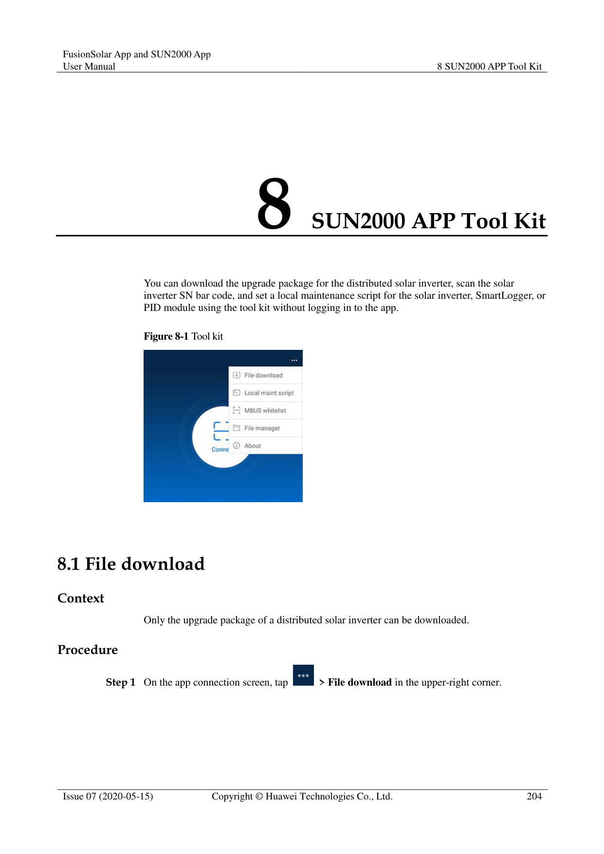
Figure 7-27 Help 2

----End
####### 7.6.3.6 About
######## Context
You can query the app version, connected product model, SN, firmware version, software version, technical support website, privacy policy (displayed only on the SUN2000 app), customer service contact information, and open source software policy.

When the app starts for the first time after being downloaded or updated, the privacy policy is displayed. You can use the app only after agreeing to the privacy policy, and the privacy policy will no longer appear. If you do not agree to the privacy policy, the app exits, and the privacy policy is still displayed when you start the app next time until you agree to the privacy policy.
You can revoke the agreed privacy policy. Procedure

Step 1 In the upper-right corner of the home screen, choose > About to view the app version, connected product model, SN, firmware version, software version, and technical support website.
########### Figure 7-28 About
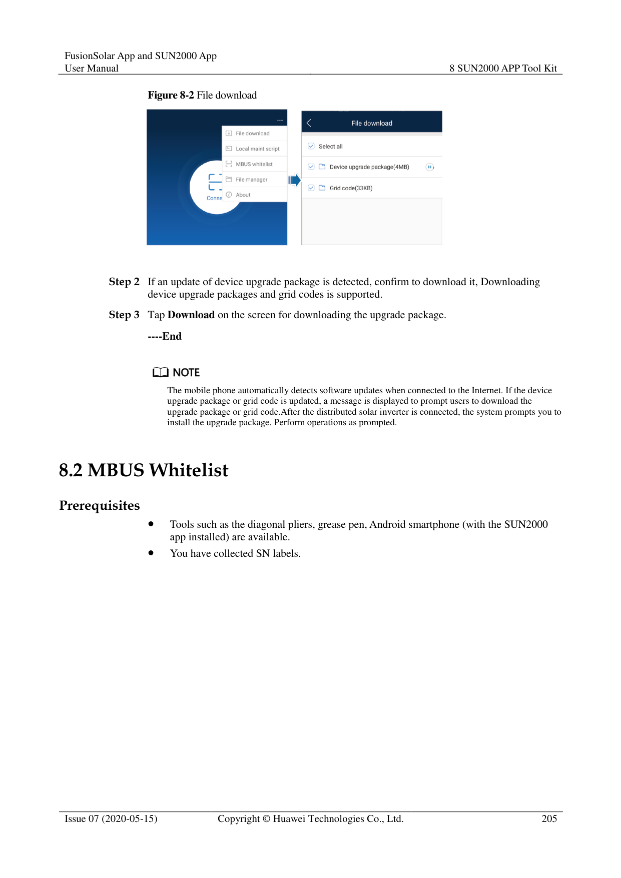

Step 2 Tap Privacy policy, Customer service contact information, or Open source software policy to view the privacy policy, customer service contact information, and open source software policy.
----End
#### 7.7 Screen Operations (Special User)7.7.1 Query
######## Procedure
Step 1 After logging in to the app, you can view the PID module working mode and compensation
mode on the home screen.
Figure 7-29 Home screen

Step 2 Tap Alarms or Running Info. to view active alarms, historical alarms, and PID module running information. You can view the following information on the alarm information screen:
Tap an alarm record and view the alarm details.
Swipe right or left on the screen or tap either Active Alarm or Historical Alarm to display a list of active alarms or historical alarms.

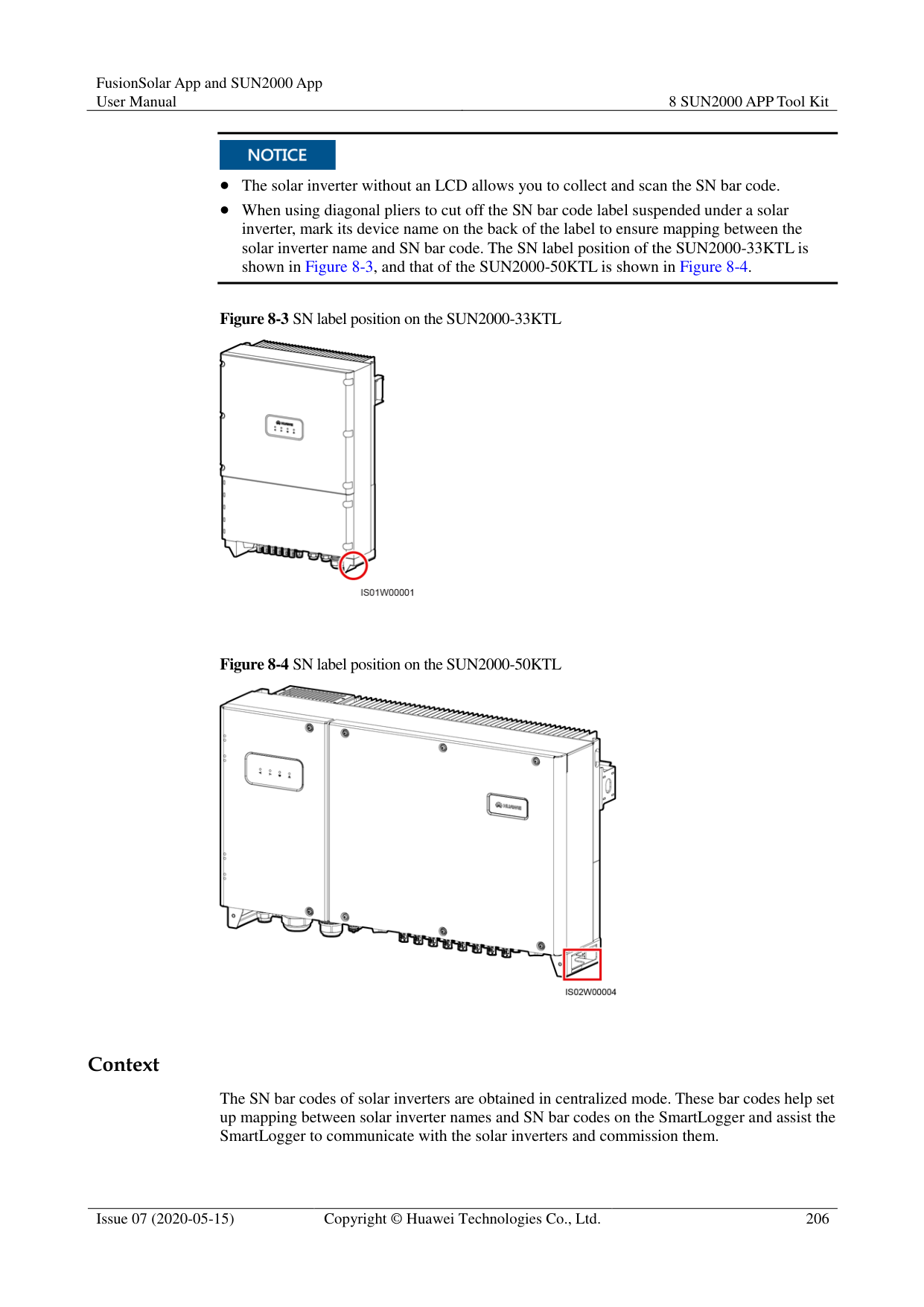

Tap to set the alarm sorting mode for active alarms or historical alarms.

Tap to set a time criterion. The historical alarms generated within the time segment are displayed.
########### ----End
##### 7.7.2 Settings
####### 7.7.2.1 Setting User Parameters
Procedure
Step 1 On the home screen, choose Settings > User Parameters to access the parameter setting
screen.
Figure 7-30 User parameters

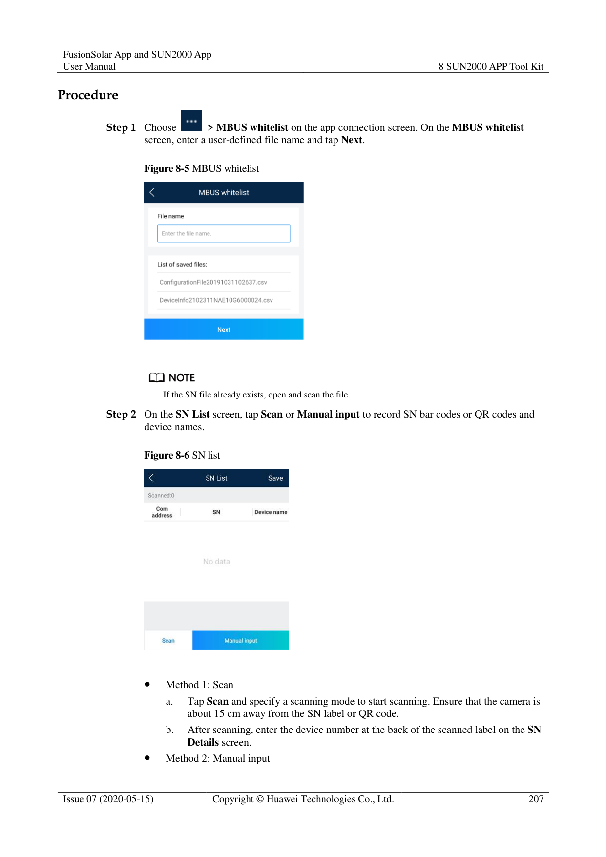

The password must meet the following requirements:
Contains six characters.
Contains at least two of the three types: lowercase letters, uppercase letters, and digits.
----End
####### 7.7.2.2 Setting a File Save Path
######## Prerequisites
This function is available only on the Android system. Context
You can modify the save path for operation logs and PID module logs and export logs from the path.
######## Procedure
Figure 7-31 File save path

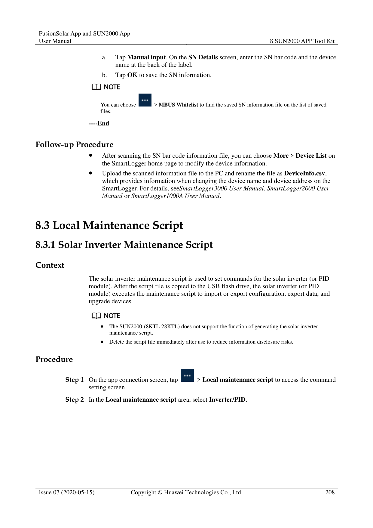
########### ----End
##### 7.7.3 Maintenance
####### 7.7.3.1 Log Download
######## Context
On the Device Logs screen, you can export operation logs and PID logs from the mobile phone.
######## Procedure
Figure 7-32 Downloading logs

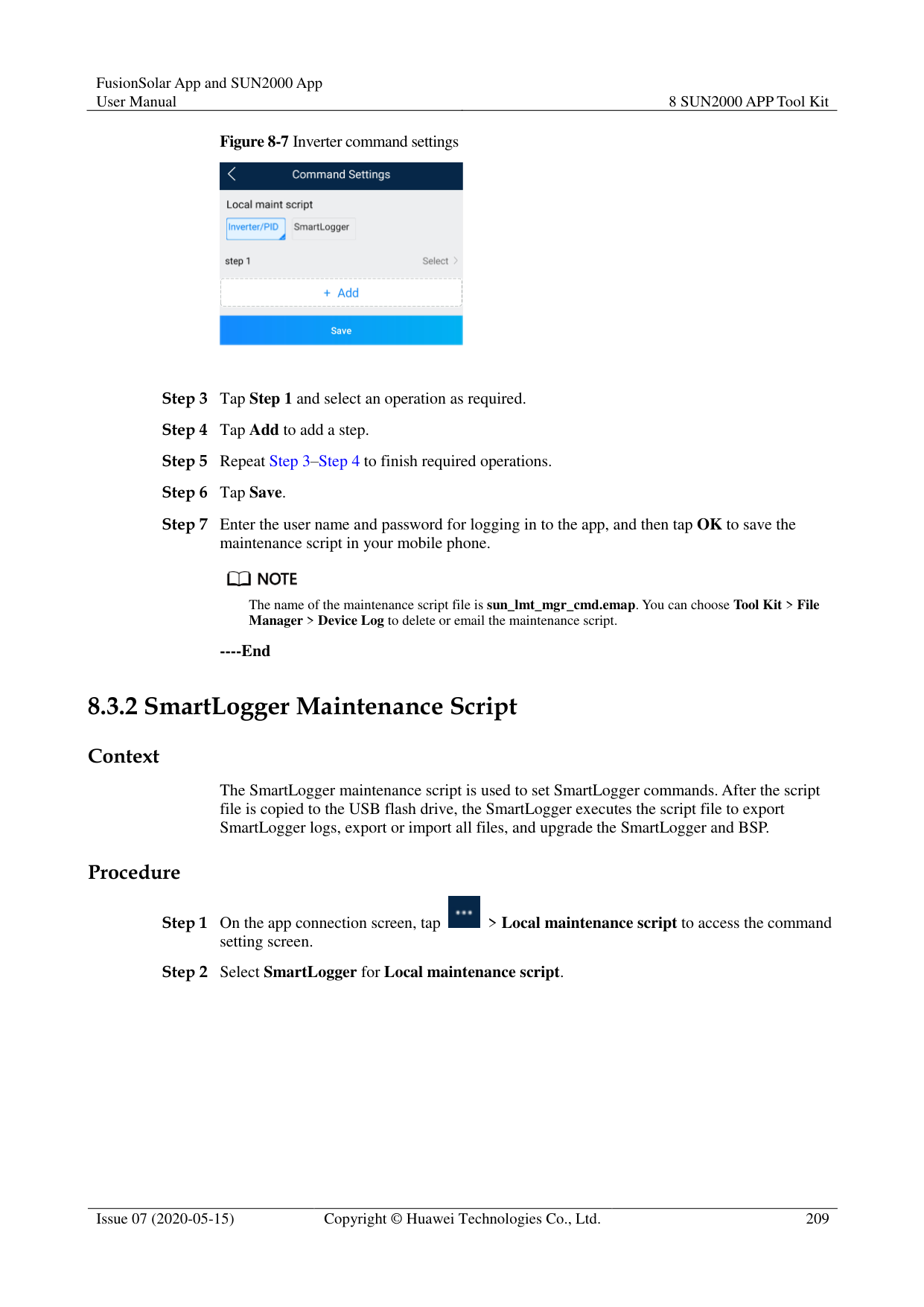

By default, Android system logs are saved in the storage/emulated/0/inverterapp folder in the phone memory. You can change the save path by referring to "Setting a File Save Path".
The downloaded solar inverter logs are saved at the Device Log directory in File Manager in your mobile phone. You can also send the logs to your mailbox for checking.
########### ----End
####### 7.7.3.2 System MaintenanceProcedure
Figure 7-33 Maintenance


If you clear data, active and historical alarms stored on the PID module will all be cleared.
Tap Performance Data to view the performance data curve of the PID module.
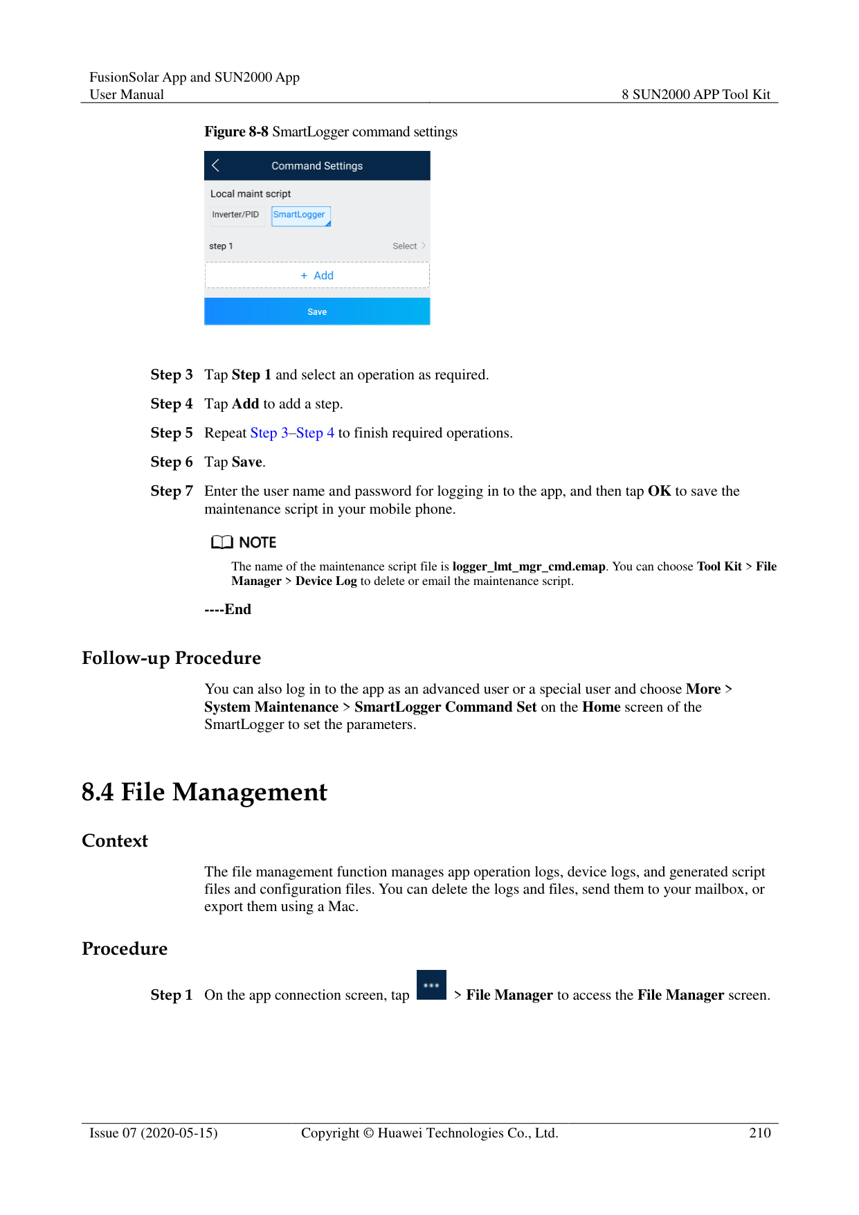
----End
####### 7.7.3.3 Device Upgrade
######## Prerequisites
Obtain the upgrade package from your supplier or Huawei engineers. Procedure
Figure 7-34 PID Upgrade

----End
####### 7.7.3.4 Feedback
######## Context
Users can provide feedback in text, pictures, and files.

Do not add private data. Procedure


Step 2 Tap Specify the type and select Feedback or Suggestion.


----End
####### 7.7.3.5 Help
######## Context
If you have any questions when using an involved device or the app, search for solutions in the help information.
######## Procedure

Step 1 Choose > Help in the upper-right corner of the home screen.
########### Figure 7-37 Help

Step 2 Specify your question. A solution will be displayed.
Figure 7-38 Help 2

----End
####### 7.7.3.6 About
######## Context
You can query the app version, connected product model, SN, firmware version, software version, technical support website, privacy policy (displayed only on the SUN2000 app), customer service contact information, and open source software policy.

When the app starts for the first time after being downloaded or updated, the privacy policy is displayed. You can use the app only after agreeing to the privacy policy, and the privacy policy will no longer appear. If you do not agree to the privacy policy, the app exits, and the privacy policy is still displayed when you start the app next time until you agree to the privacy policy.
You can revoke the agreed privacy policy. Procedure


########### ----End
8 SUN2000 APP Tool Kit
You can download the upgrade package for the distributed solar inverter, scan the solar inverter SN bar code, and set a local maintenance script for the solar inverter, SmartLogger, or PID module using the tool kit without logging in to the app.

#### 8.1 File download
######## Context
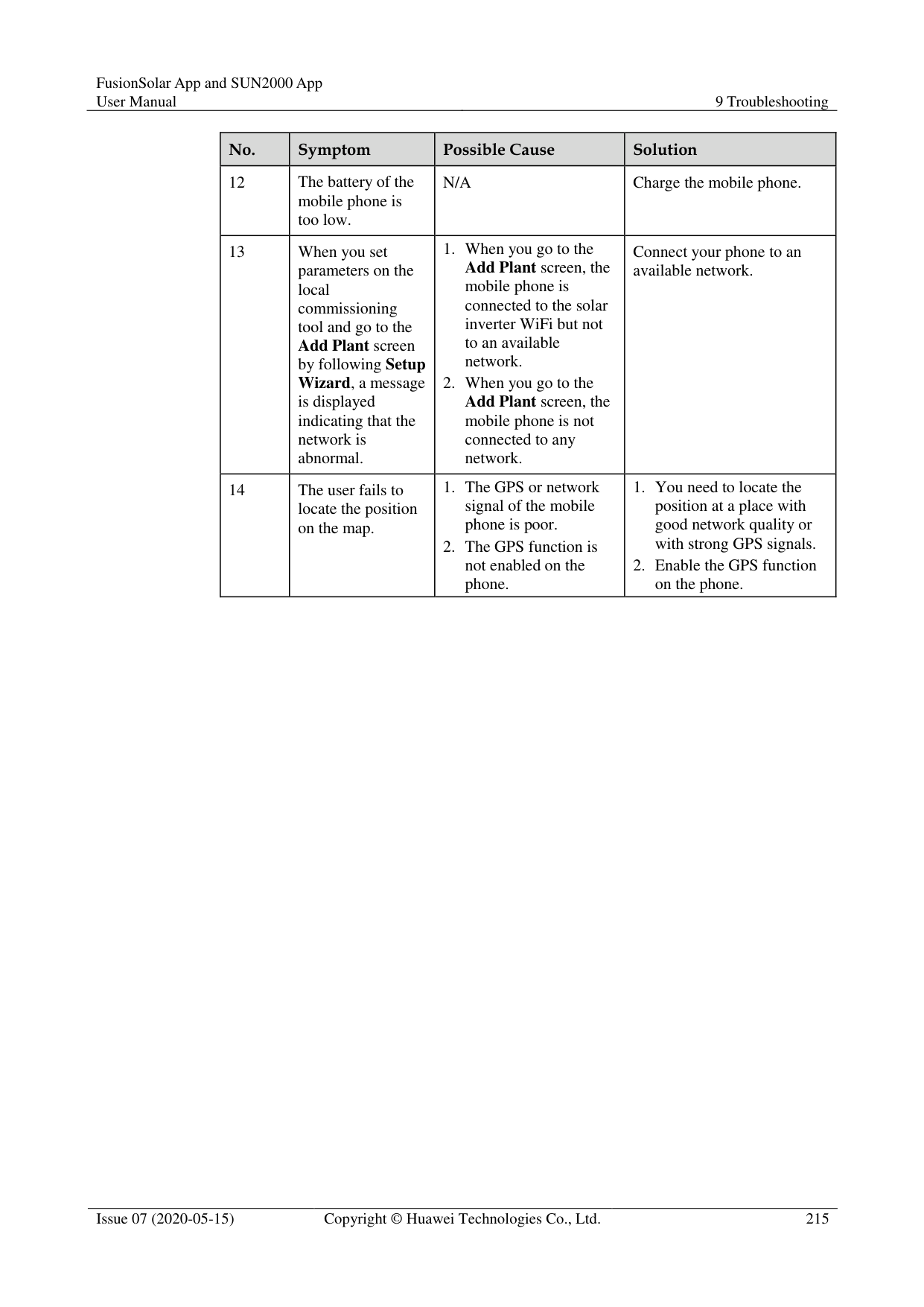
Only the upgrade package of a distributed solar inverter can be downloaded. Procedure


########### ----End

The mobile phone automatically detects software updates when connected to the Internet. If the device upgrade package or grid code is updated, a message is displayed to prompt users to download the upgrade package or grid code.After the distributed solar inverter is connected, the system prompts you to install the upgrade package. Perform operations as prompted.
#### 8.2 MBUS Whitelist
######## Prerequisites
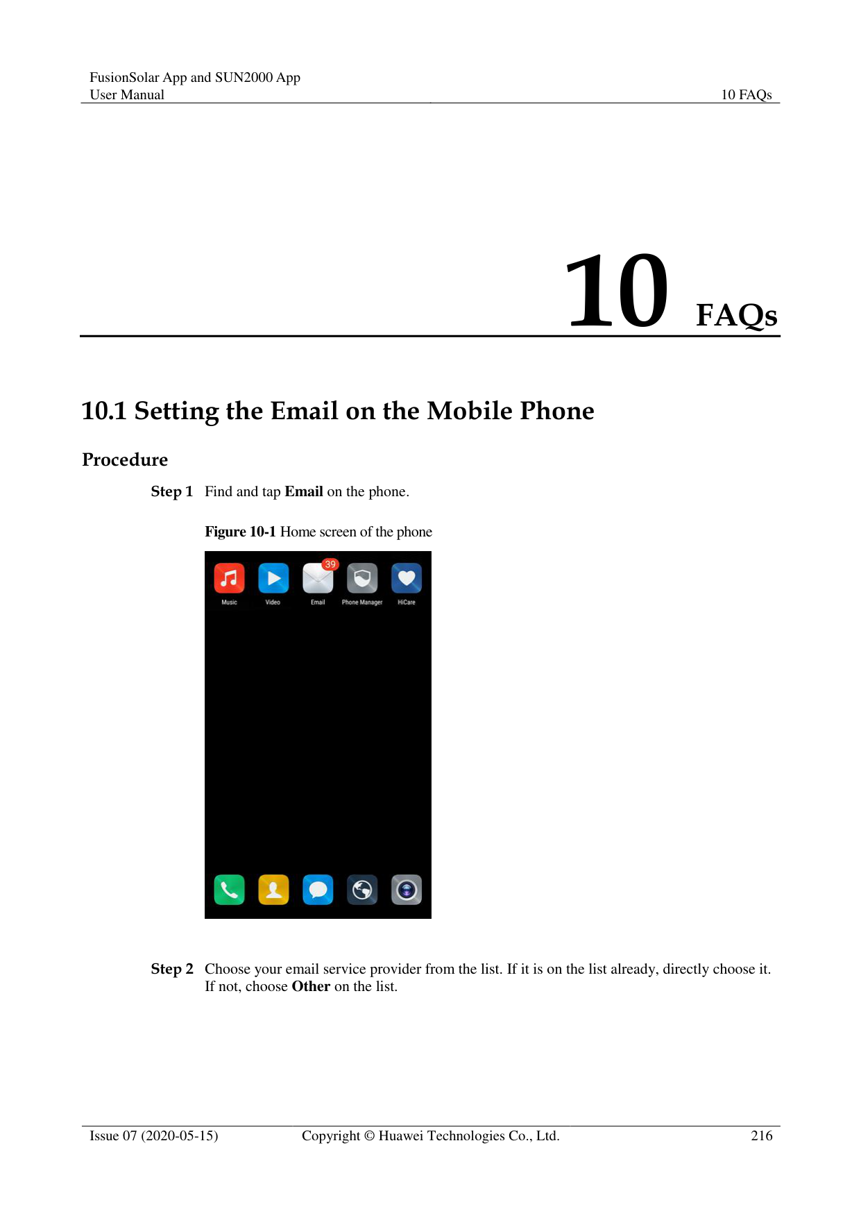
Tools such as the diagonal pliers, grease pen, Android smartphone (with the SUN2000 app installed) are available.
You have collected SN labels.

The solar inverter without an LCD allows you to collect and scan the SN bar code.
When using diagonal pliers to cut off the SN bar code label suspended under a solar inverter, mark its device name on the back of the label to ensure mapping between the solar inverter name and SN bar code. The SN label position of the SUN2000-33KTL is shown in Figure 8-3, and that of the SUN2000-50KTL is shown in Figure 8-4.


######## Context
The SN bar codes of solar inverters are obtained in centralized mode. These bar codes help set up mapping between solar inverter names and SN bar codes on the SmartLogger and assist the SmartLogger to communicate with the solar inverters and commission them.
######## Procedure
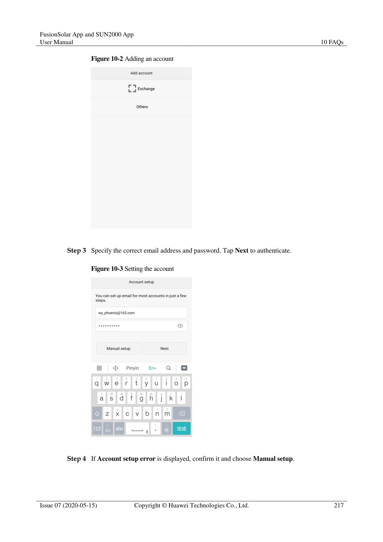

Figure 8-5 MBUS whitelist


If the SN file already exists, open and scan the file.
########### Figure 8-6 SN list

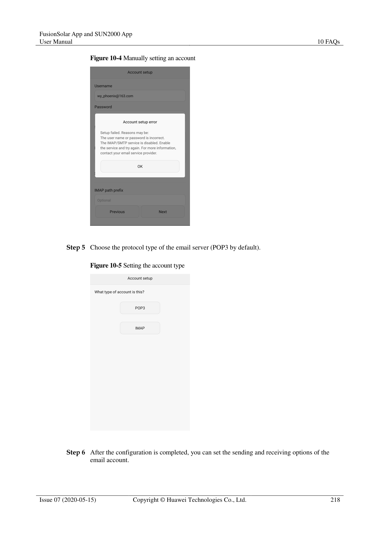


You can choose > MBUS Whitelist to find the saved SN information file on the list of saved files.
----End
######## Follow-up Procedure
After scanning the SN bar code information file, you can choose More > Device List on the SmartLogger home page to modify the device information.
Upload the scanned information file to the PC and rename the file as DeviceInfo.csv,
which provides information when changing the device name and device address on the SmartLogger. For details, seeSmartLogger3000 User Manual, SmartLogger2000 User Manual or SmartLogger1000A User Manual.
#### 8.3 Local Maintenance Script
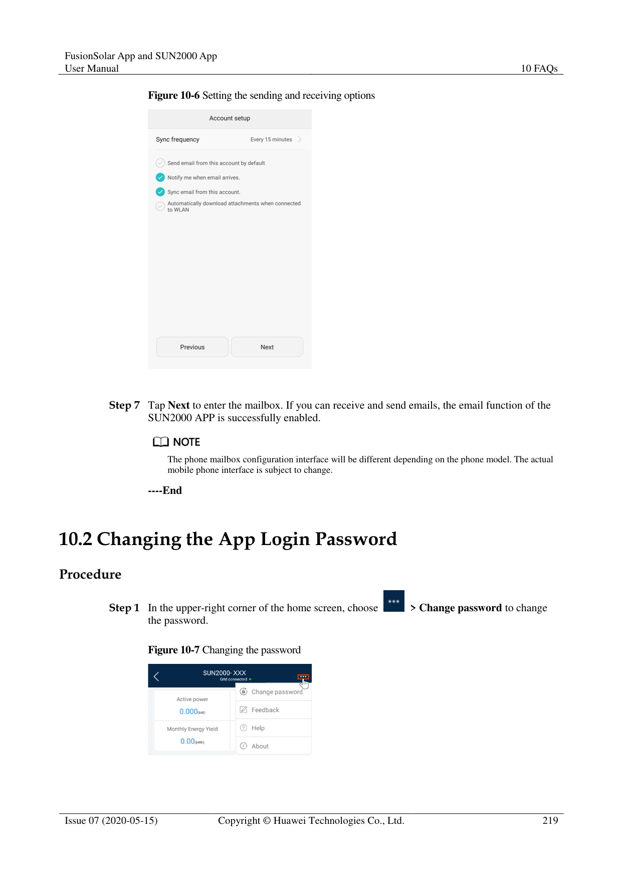
##### 8.3.1 Solar Inverter Maintenance Script
######## Context
The solar inverter maintenance script is used to set commands for the solar inverter (or PID module). After the script file is copied to the USB flash drive, the solar inverter (or PID module) executes the maintenance script to import or export configuration, export data, and upgrade devices.

The SUN2000-(8KTL-28KTL) does not support the function of generating the solar inverter maintenance script.
Delete the script file immediately after use to reduce information disclosure risks. Procedure

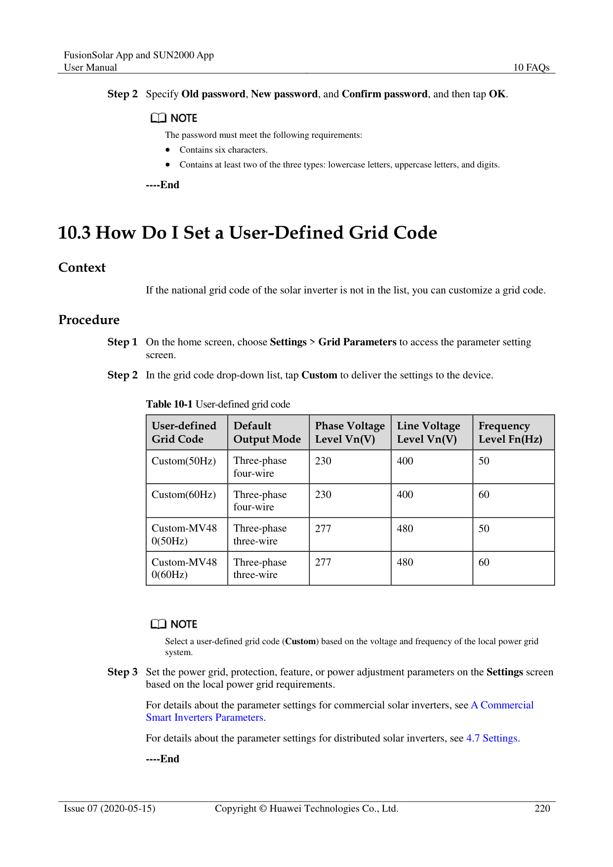


The name of the maintenance script file is sun_lmt_mgr_cmd.emap. You can choose Tool Kit > File Manager > Device Log to delete or email the maintenance script.
----End
##### 8.3.2 SmartLogger Maintenance Script
######## Context
The SmartLogger maintenance script is used to set SmartLogger commands. After the script file is copied to the USB flash drive, the SmartLogger executes the script file to export SmartLogger logs, export or import all files, and upgrade the SmartLogger and BSP.
######## Procedure


The name of the maintenance script file is logger_lmt_mgr_cmd.emap. You can choose Tool Kit > File Manager > Device Log to delete or email the maintenance script.
----End
######## Follow-up Procedure
You can also log in to the app as an advanced user or a special user and choose More > System Maintenance > SmartLogger Command Set on the Home screen of the SmartLogger to set the parameters.
#### 8.4 File Management
######## Context
The file management function manages app operation logs, device logs, and generated script files and configuration files. You can delete the logs and files, send them to your mailbox, or export them using a Mac.
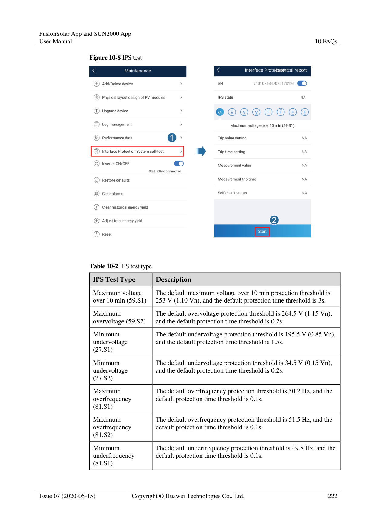
######## Procedure


----End
#### 8.5 About
######## Context
This screen is used to query the app version information, technical support website, privacy policy (displayed only on the SUN2000 app), customer service contact information, and open source software policy.

When the app starts for the first time after being downloaded or updated, the privacy policy is displayed. You can use the app only after agreeing to the privacy policy, and the privacy policy will no longer appear. If you do not agree to the privacy policy, the app exits, and the privacy policy is still displayed when you start the app next time until you agree to the privacy policy.
You can revoke the agreed privacy policy.
######## Procedure

Figure 8-10 About

########### ----End
9 Troubleshooting
Table 9-1 Troubleshooting
|No.|Symptom|Possible Cause|Solution| |---|---|---|---|
|1|The app fails to be installed.| The version of the mobile phone operating system is earlier than the required version.
Allow Installation of apps from unknown sources is not selected.| Upgrade the version of
the mobile phone operating system.
Choose Settings >
Security and select Allow Installation of apps from unknown sources.| |2|Communication failed.|1. When the mobile phone is more than 5 m away from the devices, the Bluetooth module is disconnected.
2. The USB data cable is incorrectly connected.
3. The mobile phone or router is more than 5 meters away from the solar inverter, so the WiFi connection is disconnected.
|1. Keep the mobile phone within 5 m away from the devices and reconnect the Bluetooth module.
2. Reconnect the USB data cable.
3. Keep the mobile phone or router within 5 meters of the solar inverter and reconnect the WiFi connection.
| |3|The solar inverter cannot be obtained.|An error occurs in the WiFi connection to the app.| If the solar inverter still
cannot be obtained after several attempts, log out and try again.
Check whether the WiFi connection is correct.|
|No.|Symptom|Possible Cause|Solution| |---|---|---|---| |4|The message Failed to connect to the Bluetooth. Try to connect to the system Bluetooth. is displayed.| The Bluetooth module is abnormal.
The Bluetooth module is used.| Verify that the Bluetooth module works properly.
Verify that the Bluetooth module is not used.| |5|The message Enable Bluetooth connection. is displayed.|The Bluetooth function is not enabled.|Enable the Bluetooth function.| |6|The message Failed to identify the device. Check whether the device is correctly connected. is displayed.| The WLAN module is abnormal.
The WLAN module is used| Verify that the WLAN module works properly.
Verify that the WLAN module is not used| |7|The message Failed to connect to the inverter. Please reconnect it. is displayed.|The mobile phone or router is more than 5 meters away from the solar inverter, or the WiFi signal is weak.|Ensure that the WiFi network is connected. Log out of the app and then log in again.| |8|Data failed to be obtained during operations.|1. The Bluetooth module is abnormal.
2. The USB data cable is incorrectly connected.
3. Connection to the solar inverter is disconnected.
|1. Reseat the Bluetooth module.
2. Reconnect the USB data cable.
3. Connect to the solar inverter again.
| |9|The MBUS scanning function cannot be used.|The app does not have the permission to use the camera.|Enable the app to use the camera.| |10|The label information cannot be identified when the MBUS scanning function is being used.| The scan position is incorrect, or the camera is too far away from the bar code.
The light is insufficient.
The label is blocked.| Adjust the scan position and ensure that the camera is 15 cm away from the label.
Move the label to a place with sufficient light.
Remove the blockage from the label.| |11|No upgrade package is available for an upgrade.|No upgrade package is saved in the mobile phone.|Save the upgrade package in the mobile phone.|
|No.|Symptom|Possible Cause|Solution| |---|---|---|---| |12|The battery of the mobile phone is too low.|N/A|Charge the mobile phone.| |13|When you set parameters on the local commissioning tool and go to the Add Plant screen by following Setup Wizard, a message is displayed indicating that the network is abnormal.|1. When you go to the Add Plant screen, the mobile phone is connected to the solar inverter WiFi but not to an available network.
2. When you go to the Add Plant screen, the mobile phone is not connected to any network.
|Connect your phone to an available network.| |14|The user fails to locate the position on the map.|1. The GPS or network signal of the mobile phone is poor.
2. The GPS function is not enabled on the phone.
|1. You need to locate the position at a place with good network quality or with strong GPS signals.
2. Enable the GPS function on the phone.
|
10 FAQs
#### 10.1 Setting the Email on the Mobile Phone
######## Procedure


Step 3 Specify the correct email address and password. Tap Next to authenticate.

########### Step 4 If Account setup error is displayed, confirm it and choose Manual setup.

Step 5 Choose the protocol type of the email server (POP3 by default).


The phone mailbox configuration interface will be different depending on the phone model. The actual mobile phone interface is subject to change.
----End
#### 10.2 Changing the App Login Password
######## Procedure

Figure 10-7 Changing the password

########### Step 2 Specify Old password, New password, and Confirm password, and then tap OK.

The password must meet the following requirements:
Contains six characters.
Contains at least two of the three types: lowercase letters, uppercase letters, and digits.
----End
#### 10.3 How Do I Set a User-Defined Grid Code
######## Context
If the national grid code of the solar inverter is not in the list, you can customize a grid code. Procedure
Table 10-1 User-defined grid code
|User-defined Grid Code
|Default Output Mode
|Phase Voltage Level Vn(V)
|Line Voltage Level Vn(V)
|Frequency Level Fn(Hz)
| |---|---|---|---|---| |Custom(50Hz)|Three-phase four-wire|230|400|50| |Custom(60Hz)|Three-phase four-wire|230|400|60| |Custom-MV48 0(50Hz)|Three-phase three-wire|277|480|50| |Custom-MV48 0(60Hz)|Three-phase three-wire|277|480|60|

Select a user-defined grid code (Custom) based on the voltage and frequency of the local power grid system.
For details about the parameter settings for commercial solar inverters, see A Commercial Smart Inverters Parameters.
For details about the parameter settings for distributed solar inverters, see 4.7 Settings.
########### ----End
#### 10.4 How Do I Fix WLAN Connection Failure
|Symptom|Possible Cause|Suggestion| |---|---|---| |WLAN connection failure|The WLAN network is not allowed.|Forget the WLAN network from the WLAN list in the phone system and reconnect to the network. The screen varies depending on the phone model.| |WLAN connection failure|You have entered an incorrect WLAN password.|Forget the WLAN network from the WLAN list in the phone system and reconnect to the network using the correct password. The screen varies depending on the phone model.| |WLAN connection failure|The WLAN network is being used by another phone.|Wait for the other phone to exit or restart the WLAN network.| |WLAN connection failure|The WLAN hotspot is automatically disabled because it is not used for a long time after connection.|Restart the WLAN network and search again.|

If you cannot rectify faults with the measures listed in the "Suggestion" column, contact your dealer or Huawei technical support.
#### 10.5 IPS Check (for Italy CEI0-21 Grid Code Only)
######## Function
The Italy CEI0-21 grid code requires an IPS check for the SUN2000. During the self-check, the SUN2000 checks the protection threshold and protection time of the maximum voltage over 10 min (59.S1), maximum overvoltage (59.S2), minimum undervoltage (27.S1), minimum undervoltage (27.S2), maximum overfrequency (81.S1), maximum overfrequency (81.S2), minimum underfrequency (81.S), and minimum underfrequency (81.S2).
######## Procedure
########### Figure 10-8 IPS test

Table 10-2 IPS test type
|IPS Test Type|Description| |---|---| |Maximum voltage over 10 min (59.S1)|The default maximum voltage over 10 min protection threshold is 253 V (1.10 Vn), and the default protection time threshold is 3s.| |Maximum overvoltage (59.S2)|The default overvoltage protection threshold is 264.5 V (1.15 Vn), and the default protection time threshold is 0.2s.| |Minimum undervoltage (27.S1)|The default undervoltage protection threshold is 195.5 V (0.85 Vn), and the default protection time threshold is 1.5s.|
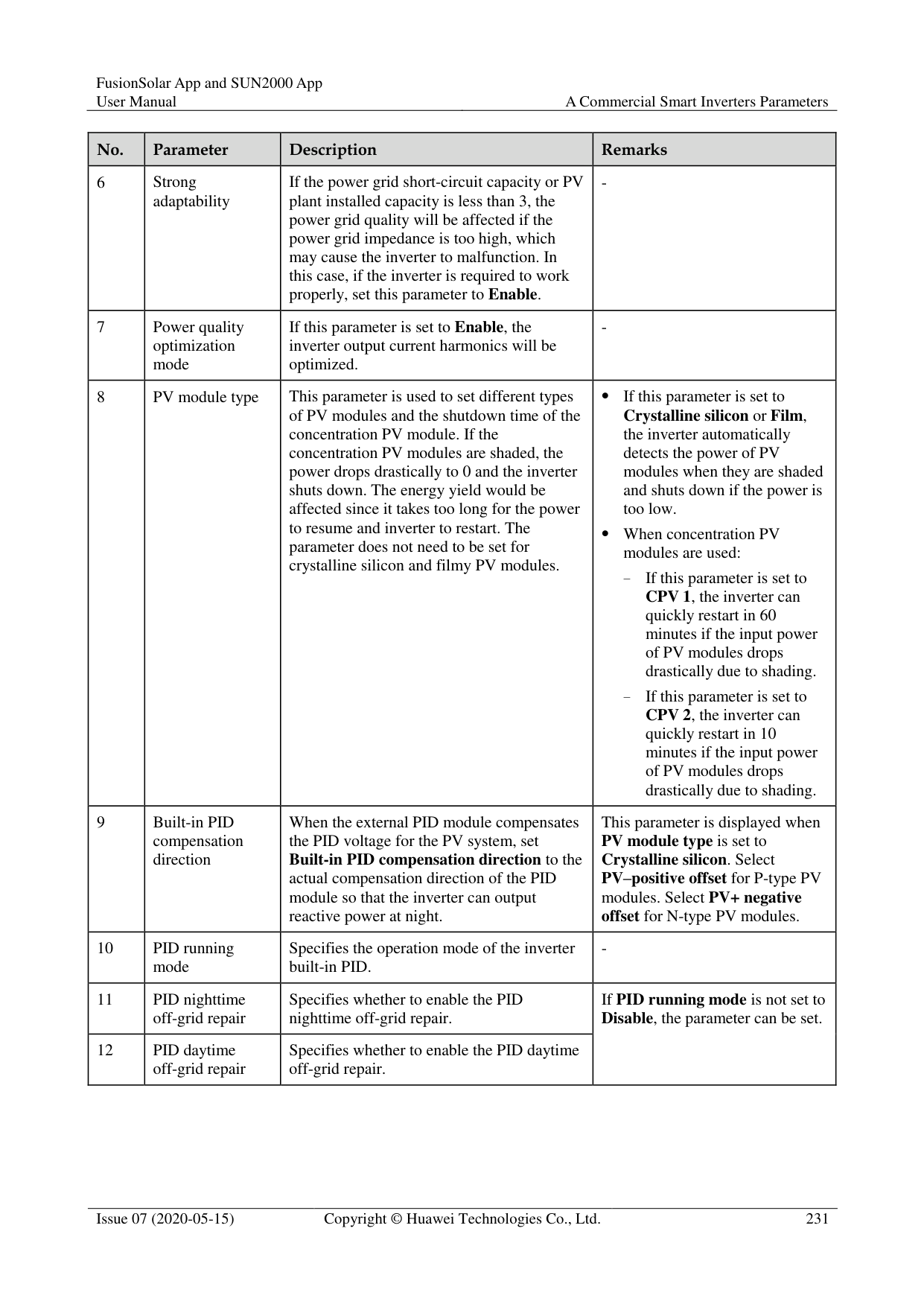
|Minimum undervoltage (27.S2)|The default undervoltage protection threshold is 34.5 V (0.15 Vn), and the default protection time threshold is 0.2s.| |Maximum overfrequency (81.S1)|The default overfrequency protection threshold is 50.2 Hz, and the default protection time threshold is 0.1s.| |Maximum overfrequency (81.S2)|The default overfrequency protection threshold is 51.5 Hz, and the default protection time threshold is 0.1s.| |Minimum underfrequency (81.S1)|The default underfrequency protection threshold is 49.8 Hz, and the default protection time threshold is 0.1s.|
|IPS Test Type|Description| |---|---| |Minimum underfrequency (81.S2)|The default underfrequency protection threshold is 47.5 Hz, and the default protection time threshold is 0.1s.|
----End
#### 10.6 How Do I Import a Grid Code?
Procedure

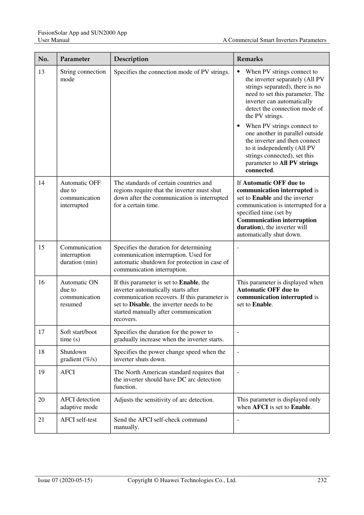
----End
#### 10.7 How Do I Change the SSID and Password of theSmartLogger Built-in WLAN?
Table 10-3
|Parameter|Description| |---|---| |SSID| Specifies the name of the built-in WLAN.
The default name of the built-in WLAN is Logger_SN.|
|Parameter|Description| |---|---| |Password| Specifies the password for accessing the built-in WLAN.
The initial password of the built-in WLAN is Changeme.
Use the initial password upon first power-on and change it immediately after login. To ensure account security, change the password periodically and keep the new password in mind. Not changing the initial password may cause password disclosure. A password left unchanged for a long period of time may be stolen or cracked. If a password is lost, the device needs to be restored to factory settings. In these cases, the user is liable for any loss caused to the PV plant.|
########### ----End
A Commercial Smart Inverters Parameters
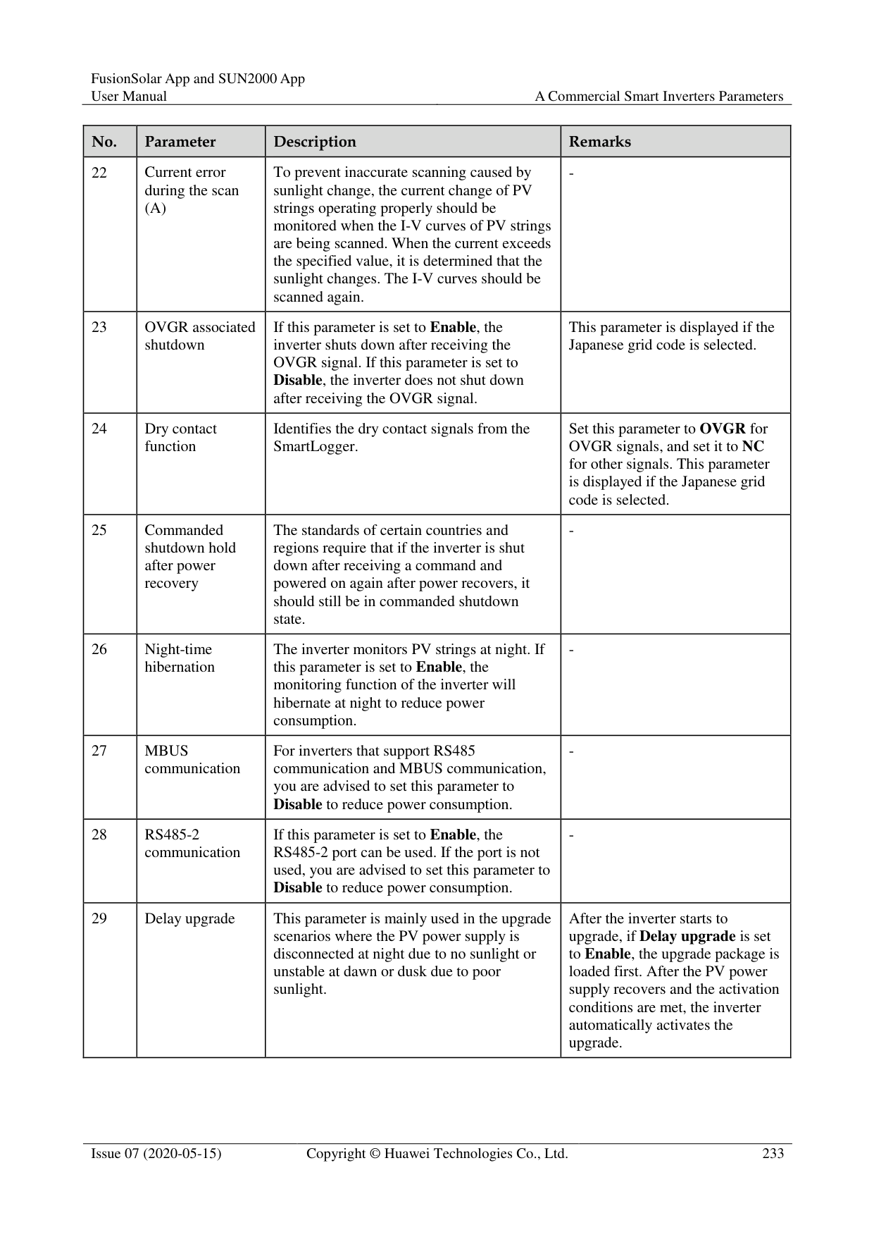
#### A.1 Grid parameters
|No.|Parameter|Description| |---|---|---| |1|Grid Code|Set this parameter based on the grid code of the country or region where the inverter is used and the inverter application scenario.| |2|Isolation settings|Set the working mode of the inverter based on the grounding status at DC side and the connection to the power grid.|
|No.|Parameter|Description| |---|---|---| |1|Grid Code|Set this parameter based on the grid code of the country or region where the inverter is used and the inverter application scenario.| |2|Isolation settings|Set the working mode of the inverter based on the grounding status at DC side and the connection to the power grid.| |3|Output mode|Specifies whether the inverter output has a neutral wire based on the application scenario.| |4|PQ mode|If this parameter is set to PQ mode 1, the maximum AC output power equals the maximum apparent power. If this parameter is set to PQ mode 2, the maximum AC output power equals the rated output power.| |5|Automatically start upon grid recovery|Specifies whether to allow the inverter to automatically start after the power grid recovers.| |6|Grid connected recovery time from grid faults (s)|Specifies the time after which the inverter begins restarting after the power grid recovers.|
|No.|Parameter|Description| |---|---|---|
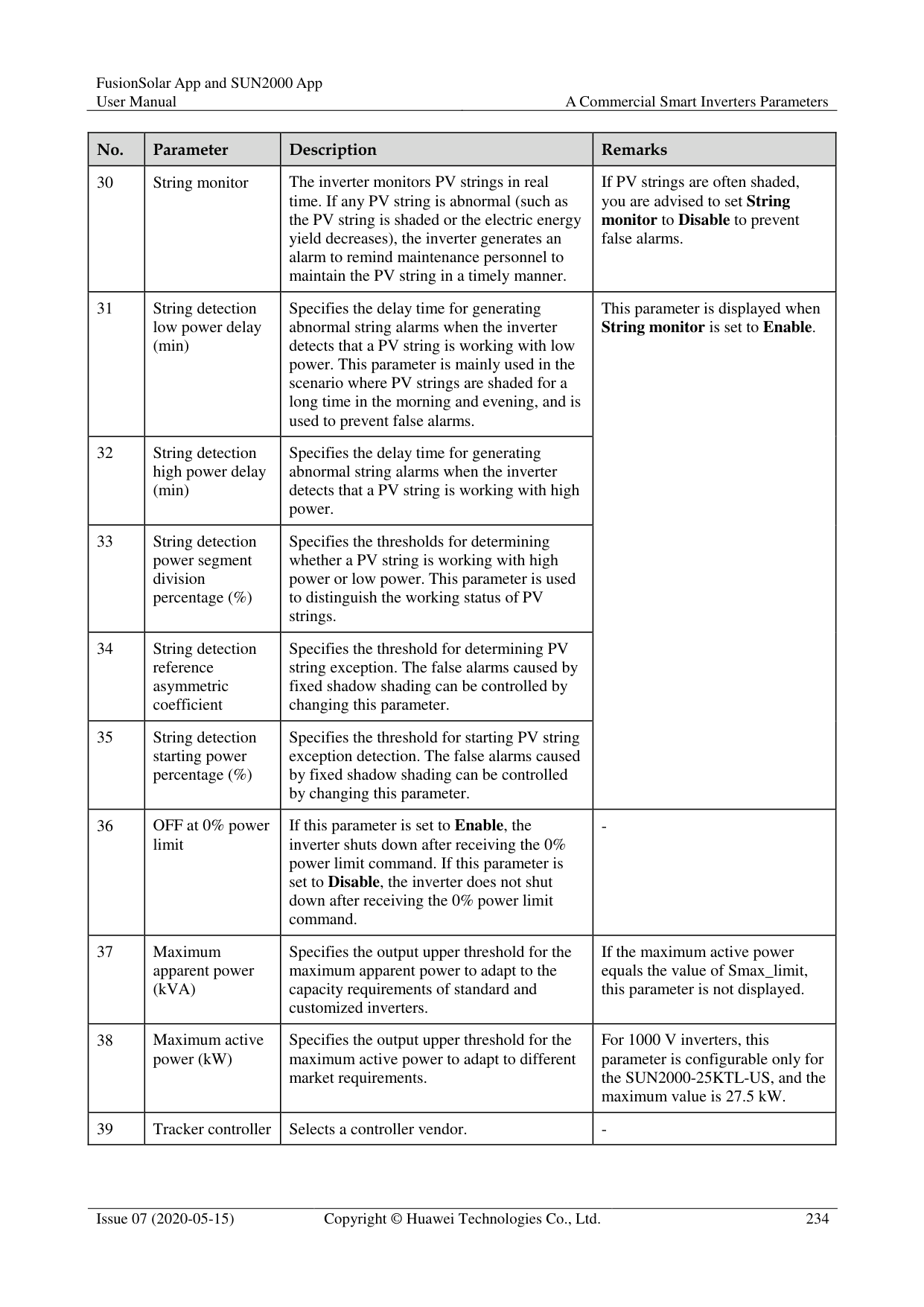
|7|Startup voltage lower threshold of grid connection (V)|According to the standards of certain countries and regions, after the inverter is powered on for the first time for grid connection, if the power grid voltage is lower than Startup voltage lower threshold of grid connection, the inverter is not allowed to connect to the grid.| |8|Startup frequency upper threshold of grid connection (Hz)|According to the standards of certain countries and regions, after the inverter is powered on for the first time for grid connection, if the power grid voltage is higher than Startup frequency upper threshold of grid connection, the inverter is not allowed to connect to the grid.| |9|Startup frequency lower threshold of grid connection (Hz)|According to the standards of certain countries and regions, after the inverter is powered on for the first time for grid connection, if the power grid voltage is lower than Startup frequency lower threshold of grid connection, the inverter is not allowed to connect to the grid.| |10|Grid reconnection voltage upper limit (V)|The standards of certain countries and regions require that after the inverter shuts down for protection due to a fault, if the power grid voltage is higher than Grid reconnection voltage upper limit, the inverter is not allowed to reconnect to the grid.| |11|Grid reconnection voltage lower limit (V)|The standards of certain countries and regions require that after the inverter shuts down for protection due to a fault, if the power grid voltage is lower than Grid reconnection voltage lower limit, the inverter is not allowed to reconnect to the grid.| |12|Grid reconnection frequency upper limit (Hz)|The standards of certain countries and regions require that after the inverter shuts down for protection due to a fault, if the power grid frequency is higher than Grid reconnection frequency upper limit, the inverter is not allowed to reconnect to the grid.| |13|Grid reconnection frequency lower limit (Hz)|The standards of certain countries and regions require that after the inverter shuts down for protection due to a fault, if the power grid frequency is lower than Grid reconnection frequency lower limit, the inverter is not allowed to reconnect to the grid.| |14|Reactive power compensation (cosφ-P) trigger voltage (%)|Specifies the voltage threshold for triggering reactive power compensation based on the cosφ-P curve.| |15|Reactive power compensation (cosφ-P) exit voltage (%)|Specifies the voltage threshold for exiting reactive power compensation based on the cosφ-P curve.|
#### A.2 Protection Parameters
|No.|Parameter|Description| |---|---|---| |1|Insulation resistance protection threshold (MΩ)|To ensure device safety, the inverter detects the insulation resistance of the input side with respect to ground when it starts a self-check. If the detected value is less than the preset value, the inverter does not connect to the grid.|
|No.|Parameter|Description| |---|---|---|
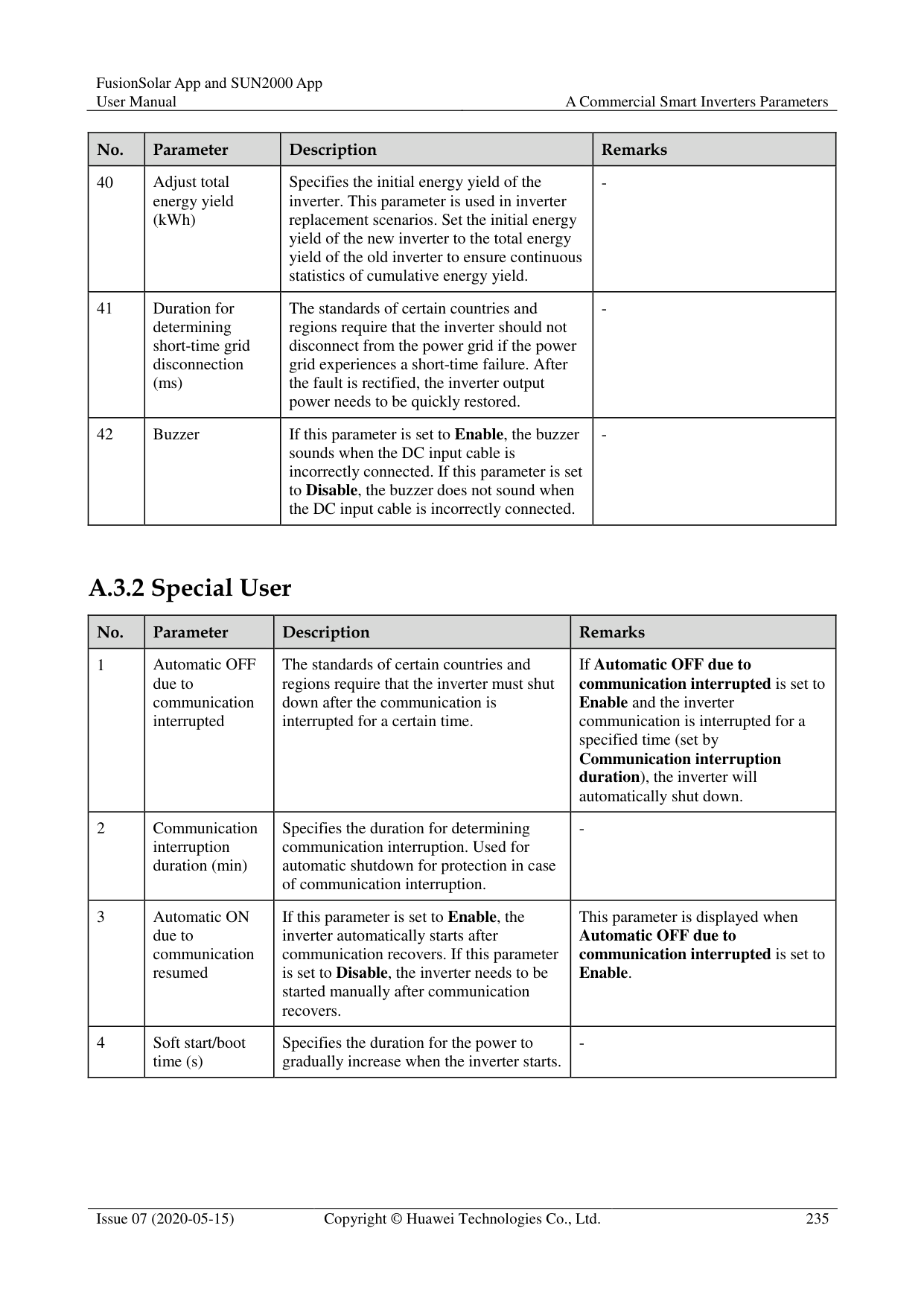
|1|Voltage unbalance protection threshold (%)|Specifies the inverter protection threshold when the power grid voltage is unbalanced.| |2|Phase protection point (º)|The Japanese standard requires that during passive islanding detection, protection should be triggered if an abrupt voltage phase change is detected.| |3|Phase angle offset protection|The standards of certain countries and regions require that the inverter needs to be protected when the phase angle offset of the power grid three phases exceeds a certain value.| |4|10-min overvoltage protection threshold (V)|Specifies the 10-minute overvoltage protection threshold.| |5|10-min overvoltage protection duration (ms)|Specifies the 10-minute overvoltage protection duration.| |6|Level-1 overvoltage protection threshold (V)|Specifies the level-1 overvoltage protection threshold.| |7|Level-1 overvoltage protection duration (ms)|Specifies the level-1 overvoltage protection duration.| |8|Level-2 overvoltage protection threshold (V)|Specifies the level-2 overvoltage protection threshold.| |9|Level-2 overvoltage protection duration (ms)|Specifies the level-2 overvoltage protection duration.| |10|Level-3 overvoltage protection threshold (V)|Specifies the level-3 overvoltage protection threshold.| |11|Level-3 overvoltage protection duration (ms)|Specifies the level-3 overvoltage protection duration.| |12|Level-4 overvoltage protection threshold (V)|Specifies the level-4 overvoltage protection threshold.| |13|Level-4 overvoltage protection duration (ms)|Specifies the level-4 overvoltage protection duration.|
|No.|Parameter|Description| |---|---|---| |14|Level-5 overvoltage protection threshold (V)|Specifies the level-5 overvoltage protection threshold.| |15|Level-5 overvoltage protection duration (ms)|Specifies the level-5 overvoltage protection duration.| |16|Level-6 overvoltage protection threshold (V)|Specifies the level-6 overvoltage protection threshold.| |17|Level-6 overvoltage protection duration (ms)|Specifies the level-6 overvoltage protection duration.| |18|Level-1 undervoltage protection threshold (V)|Specifies the level-1 undervoltage protection threshold.| |19|Level-1 undervoltage protection duration (ms)|Specifies the level-1 undervoltage protection duration.| |20|Level-2 undervoltage protection threshold (V)|Specifies the level-2 undervoltage protection threshold.| |21|Level-2 undervoltage protection duration (ms)|Specifies the level-2 undervoltage protection duration.|
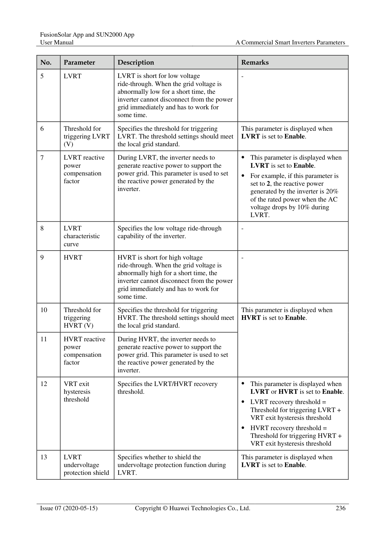
|22|Level-3 undervoltage protection threshold (V)|Specifies the level-3 undervoltage protection threshold.| |23|Level-3 undervoltage protection duration (ms)|Specifies the level-3 undervoltage protection duration.| |24|Level-4 undervoltage protection threshold (V)|Specifies the level-4 undervoltage protection threshold.| |24|Level-4 undervoltage protection duration (ms)|Specifies the level-4 undervoltage protection duration.| |26|Level-5 undervoltage protection threshold (V)|Specifies the level-5 undervoltage protection threshold.| |27|Level-5 undervoltage protection duration (ms)|Specifies the level-5 undervoltage protection duration.| |28|Level-6 undervoltage protection threshold (V)|Specifies the level-6 undervoltage protection threshold.| |29|Level-6 undervoltage protection duration (ms)|Specifies the level-6 undervoltage protection duration.| |30|Level-1 overfrequency protection threshold (Hz)|Specifies the level-1 overfrequency protection threshold.| |31|Level-1 overfrequency protection duration (ms)|Specifies the level-1 overfrequency protection duration.| |32|Level-2 overfrequency protection threshold (Hz)|Specifies the level-2 overfrequency protection threshold.|
|No.|Parameter|Description| |---|---|---| |33|Level-2 overfrequency protection duration (ms)|Specifies the level-2 overfrequency protection duration.| |34|Level-3 overfrequency protection threshold (Hz)|Specifies the level-3 overfrequency protection threshold.| |35|Level-3 overfrequency protection duration (ms)|Specifies the level-3 overfrequency protection duration.| |36|Level-4 overfrequency protection threshold (Hz)|Specifies the level-4 overfrequency protection threshold.| |37|Level-4 overfrequency protection duration (ms)|Specifies the level-4 overfrequency protection duration.| |38|Level-5 overfrequency protection threshold (Hz)|Specifies the level-5 overfrequency protection threshold.| |39|Level-5 overfrequency protection duration (ms)|Specifies the level-5 overfrequency protection duration.| |40|Level-6 overfrequency protection threshold (Hz)|Specifies the level-6 overfrequency protection threshold.| |41|Level-6 overfrequency protection duration (ms)|Specifies the level-6 overfrequency protection duration.| |42|Level-1 underfrequency protection threshold (Hz)|Specifies the level-1 underfrequency protection threshold.|
|43|Level-1 underfrequency protection duration (ms)|Specifies the level-1 underfrequency protection duration.| |44|Level-2 underfrequency protection threshold (Hz)|Specifies the level-2 underfrequency protection threshold.| |45|Level-2 underfrequency protection duration (ms)|Specifies the level-2 underfrequency protection duration.| |46|Level-3 underfrequency protection threshold (Hz)|Specifies the level-3 underfrequency protection threshold.| |47|Level-3 underfrequency protection duration (ms)|Specifies the level-3 underfrequency protection duration.| |48|Level-4 underfrequency protection threshold (Hz)|Specifies the level-4 underfrequency protection threshold.| |49|Level-4 underfrequency protection duration (ms)|Specifies the level-4 underfrequency protection duration.| |50|Level-5 underfrequency protection threshold (Hz)|Specifies the level-5 underfrequency protection threshold.| |51|Level-5 underfrequency protection duration (ms)|Specifies the level-5 underfrequency protection duration.|
|No.|Parameter|Description| |---|---|---| |52|Level-6 underfrequency protection threshold (Hz)|Specifies the level-6 underfrequency protection threshold.| |53|Level-6 underfrequency protection duration (ms)|Specifies the level-6 underfrequency protection duration.|
#### A.3 Feature parameters
|No.|Parameter|Description|Remarks| |---|---|---|---| |1|MPPT multi-peak scanning|When the inverter is used in scenarios where PV strings are greatly shaded, set this parameter to Enable, and then the inverter will perform MPPT scanning at regular intervals to locate the maximum power.|-|
|2|MPPT multi-peak scan interval (min)|Specifies the MPPT scanning interval.|This parameter is displayed when MPPT multi-peak scanning is set to Enable.| |3|RCD enhancement|RCD refers to the residual current of the inverter to the ground. To ensure device and personal safety, RCD should be limited to the specified value in the standard. If an AC switch with a residual current detection function is installed outside the inverter, this function should be enabled to reduce the residual current generated when the inverter is running, thereby preventing the AC switch from misoperations.|-| |4|Night-time reactive power output|In some specific application scenarios, a power grid company requires that the inverter can perform reactive power compensation at night to ensure that the power factor of the local power grid meets requirements.|This parameter is displayed when Isolation settings is set to Input ungrounded, with TF.| |5|PID protection at night|When the inverter outputs reactive power at night and this parameter is set to Enable, the inverter will shut down automatically if it detects abnormal status of the PID compensation.|-|
|No.|Parameter|Description|Remarks| |---|---|---|---| |6|Strong adaptability|If the power grid short-circuit capacity or PV plant installed capacity is less than 3, the power grid quality will be affected if the power grid impedance is too high, which may cause the inverter to malfunction. In this case, if the inverter is required to work properly, set this parameter to Enable.|-| |7|Power quality optimization mode|If this parameter is set to Enable, the inverter output current harmonics will be optimized.|-| |8|PV module type|This parameter is used to set different types of PV modules and the shutdown time of the concentration PV module. If the concentration PV modules are shaded, the power drops drastically to 0 and the inverter shuts down. The energy yield would be affected since it takes too long for the power to resume and inverter to restart. The parameter does not need to be set for crystalline silicon and filmy PV modules.| If this parameter is set to Crystalline silicon or Film, the inverter automatically detects the power of PV modules when they are shaded and shuts down if the power is too low.
When concentration PV modules are used: − If this parameter is set to
CPV 1, the inverter can quickly restart in 60 minutes if the input power of PV modules drops drastically due to shading.
− If this parameter is set to CPV 2, the inverter can quickly restart in 10 minutes if the input power of PV modules drops drastically due to shading.| |9|Built-in PID compensation direction|When the external PID module compensates the PID voltage for the PV system, set Built-in PID compensation direction to the actual compensation direction of the PID module so that the inverter can output reactive power at night.|This parameter is displayed when PV module type is set to Crystalline silicon. Select PV–positive offset for P-type PV
modules. Select PV+ negative offset for N-type PV modules.| |10|PID running mode|Specifies the operation mode of the inverter built-in PID.|-| |11|PID nighttime off-grid repair|Specifies whether to enable the PID nighttime off-grid repair.|If PID running mode is not set to Disable, the parameter can be set.| |12|PID daytime off-grid repair|Specifies whether to enable the PID daytime off-grid repair.|If PID running mode is not set to Disable, the parameter can be set.|
|No.|Parameter|Description|Remarks| |---|---|---|---| |13|String connection mode|Specifies the connection mode of PV strings.| When PV strings connect to the inverter separately (All PV strings separated), there is no need to set this parameter. The inverter can automatically detect the connection mode of the PV strings.
When PV strings connect to one another in parallel outside the inverter and then connect to it independently (All PV strings connected), set this parameter to All PV strings connected.| |14|Automatic OFF due to communication interrupted|The standards of certain countries and regions require that the inverter must shut down after the communication is interrupted for a certain time.|If Automatic OFF due to communication interrupted is set to Enable and the inverter communication is interrupted for a specified time (set by
Communication interruption duration), the inverter will automatically shut down.| |15|Communication interruption duration (min)|Specifies the duration for determining communication interruption. Used for automatic shutdown for protection in case of communication interruption.|-| |16|Automatic ON due to communication resumed|If this parameter is set to Enable, the inverter automatically starts after communication recovers. If this parameter is set to Disable, the inverter needs to be started manually after communication recovers.|This parameter is displayed when Automatic OFF due to communication interrupted is set to Enable.| |17|Soft start/boot time (s)|Specifies the duration for the power to gradually increase when the inverter starts.|-| |18|Shutdown gradient (%/s)|Specifies the power change speed when the inverter shuts down.|-|
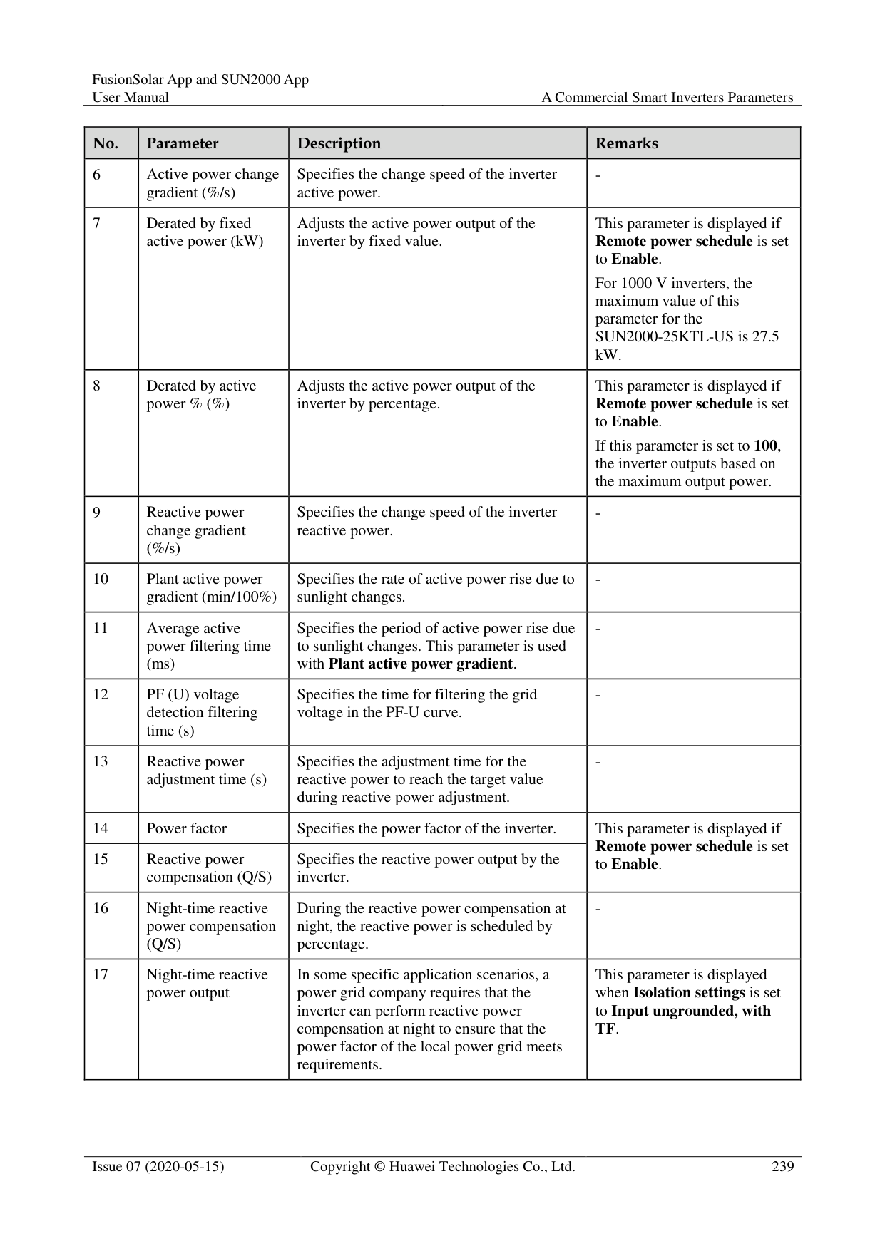
|19|AFCI|The North American standard requires that the inverter should have DC arc detection function.|-| |20|AFCI detection adaptive mode|Adjusts the sensitivity of arc detection.|This parameter is displayed only when AFCI is set to Enable.| |21|AFCI self-test|Send the AFCI self-check command manually.|-|
|No.|Parameter|Description|Remarks| |---|---|---|---| |22|Current error during the scan (A)|To prevent inaccurate scanning caused by sunlight change, the current change of PV strings operating properly should be monitored when the I-V curves of PV strings are being scanned. When the current exceeds the specified value, it is determined that the sunlight changes. The I-V curves should be scanned again.|-| |23|OVGR associated shutdown|If this parameter is set to Enable, the inverter shuts down after receiving the OVGR signal. If this parameter is set to Disable, the inverter does not shut down after receiving the OVGR signal.|This parameter is displayed if the Japanese grid code is selected.| |24|Dry contact function|Identifies the dry contact signals from the SmartLogger.|Set this parameter to OVGR for OVGR signals, and set it to NC for other signals. This parameter is displayed if the Japanese grid code is selected.| |25|Commanded shutdown hold after power recovery|The standards of certain countries and regions require that if the inverter is shut down after receiving a command and powered on again after power recovers, it should still be in commanded shutdown state.|-| |26|Night-time hibernation|The inverter monitors PV strings at night. If this parameter is set to Enable, the monitoring function of the inverter will hibernate at night to reduce power consumption.|-| |27|MBUS communication|For inverters that support RS485 communication and MBUS communication, you are advised to set this parameter to Disable to reduce power consumption.|-| |28|RS485-2 communication|If this parameter is set to Enable, the RS485-2 port can be used. If the port is not used, you are advised to set this parameter to Disable to reduce power consumption.|-| |29|Delay upgrade|This parameter is mainly used in the upgrade scenarios where the PV power supply is disconnected at night due to no sunlight or unstable at dawn or dusk due to poor sunlight.|After the inverter starts to upgrade, if Delay upgrade is set to Enable, the upgrade package is loaded first. After the PV power supply recovers and the activation conditions are met, the inverter automatically activates the upgrade.|
|No.|Parameter|Description|Remarks| |---|---|---|---| |30|String monitor|The inverter monitors PV strings in real time. If any PV string is abnormal (such as the PV string is shaded or the electric energy yield decreases), the inverter generates an alarm to remind maintenance personnel to maintain the PV string in a timely manner.|If PV strings are often shaded, you are advised to set String monitor to Disable to prevent false alarms.| |31|String detection low power delay (min)|Specifies the delay time for generating abnormal string alarms when the inverter detects that a PV string is working with low power. This parameter is mainly used in the scenario where PV strings are shaded for a long time in the morning and evening, and is used to prevent false alarms.|This parameter is displayed when String monitor is set to Enable.| |32|String detection high power delay (min)|Specifies the delay time for generating abnormal string alarms when the inverter detects that a PV string is working with high power.|This parameter is displayed when String monitor is set to Enable.| |33|String detection power segment division percentage (%)|Specifies the thresholds for determining whether a PV string is working with high power or low power. This parameter is used to distinguish the working status of PV strings.|This parameter is displayed when String monitor is set to Enable.| |34|String detection reference asymmetric coefficient|Specifies the threshold for determining PV string exception. The false alarms caused by fixed shadow shading can be controlled by changing this parameter.|This parameter is displayed when String monitor is set to Enable.| |35|String detection starting power percentage (%)|Specifies the threshold for starting PV string exception detection. The false alarms caused by fixed shadow shading can be controlled by changing this parameter.|This parameter is displayed when String monitor is set to Enable.|
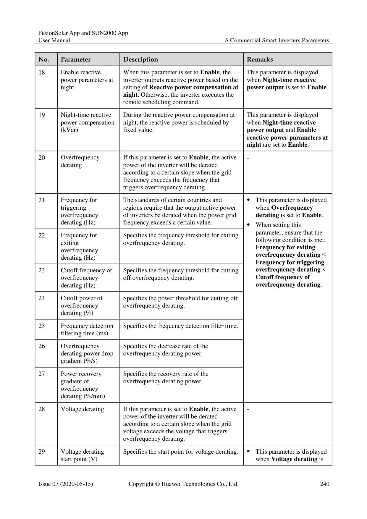
|36|OFF at 0% power limit|If this parameter is set to Enable, the inverter shuts down after receiving the 0% power limit command. If this parameter is set to Disable, the inverter does not shut down after receiving the 0% power limit command.|-| |37|Maximum apparent power (kVA)|Specifies the output upper threshold for the maximum apparent power to adapt to the capacity requirements of standard and customized inverters.|If the maximum active power equals the value of Smax_limit, this parameter is not displayed.| |38|Maximum active power (kW)|Specifies the output upper threshold for the maximum active power to adapt to different market requirements.|For 1000 V inverters, this parameter is configurable only for the SUN2000-25KTL-US, and the maximum value is 27.5 kW.| |39|Tracker controller|Selects a controller vendor.|-|
|No.|Parameter|Description|Remarks| |---|---|---|---| |40|Adjust total energy yield (kWh)|Specifies the initial energy yield of the inverter. This parameter is used in inverter replacement scenarios. Set the initial energy yield of the new inverter to the total energy yield of the old inverter to ensure continuous statistics of cumulative energy yield.|-| |41|Duration for determining short-time grid disconnection (ms)|The standards of certain countries and regions require that the inverter should not disconnect from the power grid if the power grid experiences a short-time failure. After the fault is rectified, the inverter output power needs to be quickly restored.|-| |42|Buzzer|If this parameter is set to Enable, the buzzer sounds when the DC input cable is incorrectly connected. If this parameter is set to Disable, the buzzer does not sound when the DC input cable is incorrectly connected.|-|
##### A.3.2 Special User
|No.|Parameter|Description|Remarks| |---|---|---|---| |1|Automatic OFF due to communication interrupted|The standards of certain countries and regions require that the inverter must shut down after the communication is interrupted for a certain time.|If Automatic OFF due to communication interrupted is set to Enable and the inverter communication is interrupted for a specified time (set by
Communication interruption duration), the inverter will automatically shut down.| |2|Communication interruption duration (min)|Specifies the duration for determining communication interruption. Used for automatic shutdown for protection in case of communication interruption.|-| |3|Automatic ON due to communication resumed|If this parameter is set to Enable, the inverter automatically starts after communication recovers. If this parameter is set to Disable, the inverter needs to be started manually after communication recovers.|This parameter is displayed when Automatic OFF due to communication interrupted is set to Enable.| |4|Soft start/boot time (s)|Specifies the duration for the power to gradually increase when the inverter starts.|-|
|No.|Parameter|Description|Remarks| |---|---|---|---|
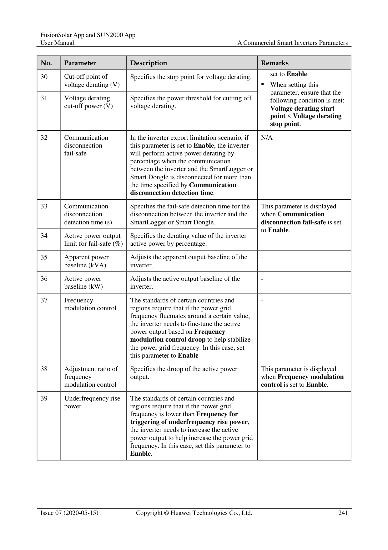
|5|LVRT|LVRT is short for low voltage ride-through. When the grid voltage is abnormally low for a short time, the inverter cannot disconnect from the power grid immediately and has to work for some time.|-| |6|Threshold for triggering LVRT (V)|Specifies the threshold for triggering LVRT. The threshold settings should meet the local grid standard.|This parameter is displayed when LVRT is set to Enable.| |7|LVRT reactive power compensation factor|During LVRT, the inverter needs to generate reactive power to support the power grid. This parameter is used to set the reactive power generated by the inverter.| This parameter is displayed when
LVRT is set to Enable.
For example, if this parameter is set to 2, the reactive power generated by the inverter is 20% of the rated power when the AC voltage drops by 10% during LVRT.| |8|LVRT characteristic curve|Specifies the low voltage ride-through capability of the inverter.|-| |9|HVRT|HVRT is short for high voltage ride-through. When the grid voltage is abnormally high for a short time, the inverter cannot disconnect from the power grid immediately and has to work for some time.|-| |10|Threshold for triggering HVRT (V)|Specifies the threshold for triggering HVRT. The threshold settings should meet the local grid standard.|This parameter is displayed when HVRT is set to Enable.
| |11|HVRT reactive power compensation factor|During HVRT, the inverter needs to generate reactive power to support the power grid. This parameter is used to set the reactive power generated by the inverter.|This parameter is displayed when HVRT is set to Enable.
| |12|VRT exit hysteresis threshold|Specifies the LVRT/HVRT recovery threshold.| This parameter is displayed when
LVRT or HVRT is set to Enable.
LVRT recovery threshold = Threshold for triggering LVRT + VRT exit hysteresis threshold
HVRT recovery threshold = Threshold for triggering HVRT + VRT exit hysteresis threshold| |13|LVRT undervoltage protection shield|Specifies whether to shield the undervoltage protection function during LVRT.|This parameter is displayed when LVRT is set to Enable.|
|No.|Parameter|Description|Remarks| |---|---|---|---| |14|Grid voltage protection shield during VRT|Specifies whether to shield the undervoltage protection function during LVRT or HVRT.|This parameter is displayed when LVRT or HVRT is set to Enable.| |15|Grid voltage jump triggering threshold (%)|Specifies the LVRT or HVRT threshold for triggering a transient voltage jump of a power grid. A transient voltage jump indicates that the inverter cannot immediately disconnect from the power grid when the power grid is abnormal due to transient changes.|This parameter is available when Grid code is set to VDE 4120.| |16|Zero current due to power grid fault|Certain countries and regions have requirements on the output current during high/low voltage ride-through. In this case, set this parameter to Enable. After this parameter is set to Enable, the output current is less than 10% of the rated current during high/low voltage ride-through.|This parameter is displayed when LVRT or HVRT is set to Enable.| |17|Active islanding protection|Specifies whether to enable the active islanding protection function.|-| |18|Passive islanding protection|Specifies whether to enable the passive islanding protection function.|This parameter is displayed if the Japanese grid code is selected.| |19|Voltage rise suppression|The standards of certain countries and regions require that when the output voltage exceeds a certain value, the inverter must suppress voltage rise by outputting reactive power and reducing active power.|-| |20|Voltage rise suppressing reactive power adjustment point (%)|The standards of certain countries and regions require that the inverter generate a certain amount of reactive power when the output voltage exceeds a certain value.| This parameter is displayed when Voltage rise suppression is set to Enable.
The value of Voltage rise suppressing active power derating point must be greater than that of Voltage rise suppressing reactive power adjustment point.| |21|Voltage rise suppressing active power derating point (%)|The standards of certain countries and regions require that the active power of the inverter be derated according to a certain slope when the output voltage exceeds a certain value.| This parameter is displayed when Voltage rise suppression is set to Enable.
The value of Voltage rise suppressing active power derating point must be greater than that of Voltage rise suppressing reactive power adjustment point.| |22|Voltage rise suppression P-U curve|The standards of certain countries and regions require that the P-U curve be set.|This parameter is displayed when Voltage rise suppression is set to Enable.| |23|Voltage rise suppression Q-U curve|The standards of certain countries and regions require that the Q-U curve be set.|This parameter is displayed when Voltage rise suppression is set to Enable.|
|No.|Parameter|Description|Remarks| |---|---|---|---| |24|Frequency change rate protection|Set this parameter to Enable to protect the inverter when the grid frequency changes too fast.|-| |25|Frequency change rate protection threshold (Hz/s)|Specifies the frequency change rate protection threshold.|This parameter is displayed if Frequency change rate protection is set to Enable.| |26|Frequency change rate protection duration (s)|The inverter is protected when the grid frequency change duration exceeds the value.|This parameter is displayed if Frequency change rate protection is set to Enable.| |27|Soft start time after grid failure (s)|Specifies the time for the power to gradually increase when the inverter restarts after the power grid recovers.|-|
#### A.4 Power adjustment parametersA.4.1 Special User
|No.|Parameter|Description|Remarks| |---|---|---|---| |1|Remote power schedule|If this parameter is set to Enable, the inverter responds to the scheduling instruction from the remote port. If this parameter is set to Disable, the inverter does not respond to the scheduling instruction from the remote port.|-| |2|Schedule instruction valid duration (s)|Specifies the time for maintaining the scheduling instruction.|When this parameter is set to 0, the scheduling instruction takes effect permanently.| |3|Maximum apparent power (kVA)|Specifies the output upper threshold for the maximum apparent power to adapt to the capacity requirements of standard and customized inverters.|If the maximum active power equals the value of Smax_limit, this parameter is not displayed.| |4|Maximum active power (kW)|Specifies the output upper threshold for the maximum active power to adapt to different market requirements.|-| |5|OFF at 0% power limit|If this parameter is set to Enable, the inverter shuts down after receiving the 0% power limit command. If this parameter is set to Disable, the inverter does not shut down after receiving the 0% power limit command.|-|
|No.|Parameter|Description|Remarks| |---|---|---|---| |6|Active power change gradient (%/s)|Specifies the change speed of the inverter active power.|-| |7|Derated by fixed active power (kW)|Adjusts the active power output of the inverter by fixed value.|This parameter is displayed if Remote power schedule is set to Enable. For 1000 V inverters, the maximum value of this parameter for the SUN2000-25KTL-US is 27.5 kW.| |8|Derated by active power % (%)|Adjusts the active power output of the inverter by percentage.|This parameter is displayed if Remote power schedule is set to Enable. If this parameter is set to 100, the inverter outputs based on the maximum output power.| |9|Reactive power change gradient (%/s)|Specifies the change speed of the inverter reactive power.|-|
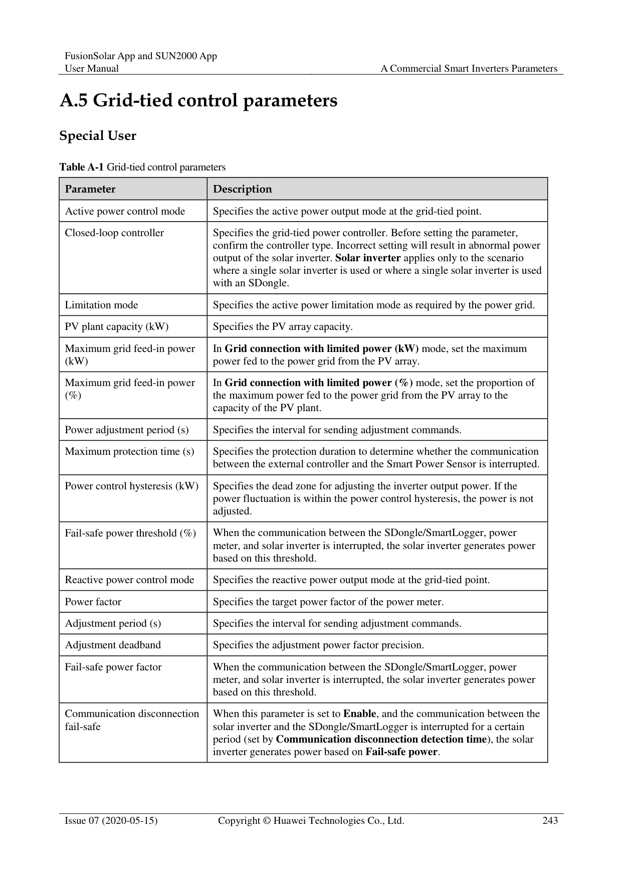
|10|Plant active power gradient (min/100%)|Specifies the rate of active power rise due to sunlight changes.|-| |11|Average active power filtering time (ms)|Specifies the period of active power rise due to sunlight changes. This parameter is used with Plant active power gradient.|-| |12|PF (U) voltage detection filtering time (s)|Specifies the time for filtering the grid voltage in the PF-U curve.|-| |13|Reactive power adjustment time (s)|Specifies the adjustment time for the reactive power to reach the target value during reactive power adjustment.|-| |14|Power factor|Specifies the power factor of the inverter.|This parameter is displayed if Remote power schedule is set to Enable.| |15|Reactive power compensation (Q/S)|Specifies the reactive power output by the inverter.|This parameter is displayed if Remote power schedule is set to Enable.| |16|Night-time reactive power compensation (Q/S)|During the reactive power compensation at night, the reactive power is scheduled by percentage.|-| |17|Night-time reactive power output|In some specific application scenarios, a power grid company requires that the inverter can perform reactive power compensation at night to ensure that the power factor of the local power grid meets requirements.|This parameter is displayed when Isolation settings is set to Input ungrounded, with TF.|
|No.|Parameter|Description|Remarks| |---|---|---|---| |18|Enable reactive power parameters at night|When this parameter is set to Enable, the inverter outputs reactive power based on the setting of Reactive power compensation at night. Otherwise, the inverter executes the remote scheduling command.|This parameter is displayed when Night-time reactive power output is set to Enable.| |19|Night-time reactive power compensation (kVar)|During the reactive power compensation at night, the reactive power is scheduled by fixed value.|This parameter is displayed when Night-time reactive power output and Enable reactive power parameters at night are set to Enable.| |20|Overfrequency derating|If this parameter is set to Enable, the active power of the inverter will be derated according to a certain slope when the grid frequency exceeds the frequency that triggers overfrequency derating.|-| |21|Frequency for triggering overfrequency derating (Hz)|The standards of certain countries and regions require that the output active power of inverters be derated when the power grid frequency exceeds a certain value.| This parameter is displayed when Overfrequency derating is set to Enable.
When setting this parameter, ensure that the following condition is met: Frequency for exiting overfrequency derating ≤ Frequency for triggering overfrequency derating < Cutoff frequency of overfrequency derating.| |22|Frequency for exiting overfrequency derating (Hz)|Specifies the frequency threshold for exiting overfrequency derating.| This parameter is displayed when Overfrequency derating is set to Enable.
When setting this parameter, ensure that the following condition is met: Frequency for exiting overfrequency derating ≤ Frequency for triggering overfrequency derating < Cutoff frequency of overfrequency derating.| |23|Cutoff frequency of overfrequency derating (Hz)|Specifies the frequency threshold for cutting off overfrequency derating.| This parameter is displayed when Overfrequency derating is set to Enable.
When setting this parameter, ensure that the following condition is met: Frequency for exiting overfrequency derating ≤ Frequency for triggering overfrequency derating < Cutoff frequency of overfrequency derating.| |24|Cutoff power of overfrequency derating (%)|Specifies the power threshold for cutting off overfrequency derating.| This parameter is displayed when Overfrequency derating is set to Enable.
When setting this parameter, ensure that the following condition is met: Frequency for exiting overfrequency derating ≤ Frequency for triggering overfrequency derating < Cutoff frequency of overfrequency derating.| |25|Frequency detection filtering time (ms)|Specifies the frequency detection filter time.| This parameter is displayed when Overfrequency derating is set to Enable.
When setting this parameter, ensure that the following condition is met: Frequency for exiting overfrequency derating ≤ Frequency for triggering overfrequency derating < Cutoff frequency of overfrequency derating.| |26|Overfrequency derating power drop gradient (%/s)|Specifies the decrease rate of the overfrequency derating power.| This parameter is displayed when Overfrequency derating is set to Enable.
When setting this parameter, ensure that the following condition is met: Frequency for exiting overfrequency derating ≤ Frequency for triggering overfrequency derating < Cutoff frequency of overfrequency derating.| |27|Power recovery gradient of overfrequency derating (%/min)|Specifies the recovery rate of the overfrequency derating power.| This parameter is displayed when Overfrequency derating is set to Enable.
When setting this parameter, ensure that the following condition is met: Frequency for exiting overfrequency derating ≤ Frequency for triggering overfrequency derating < Cutoff frequency of overfrequency derating.| |28|Voltage derating|If this parameter is set to Enable, the active power of the inverter will be derated according to a certain slope when the grid voltage exceeds the voltage that triggers overfrequency derating.|-| |29|Voltage derating start point (V)|Specifies the start point for voltage derating.| This parameter is displayed when Voltage derating is|
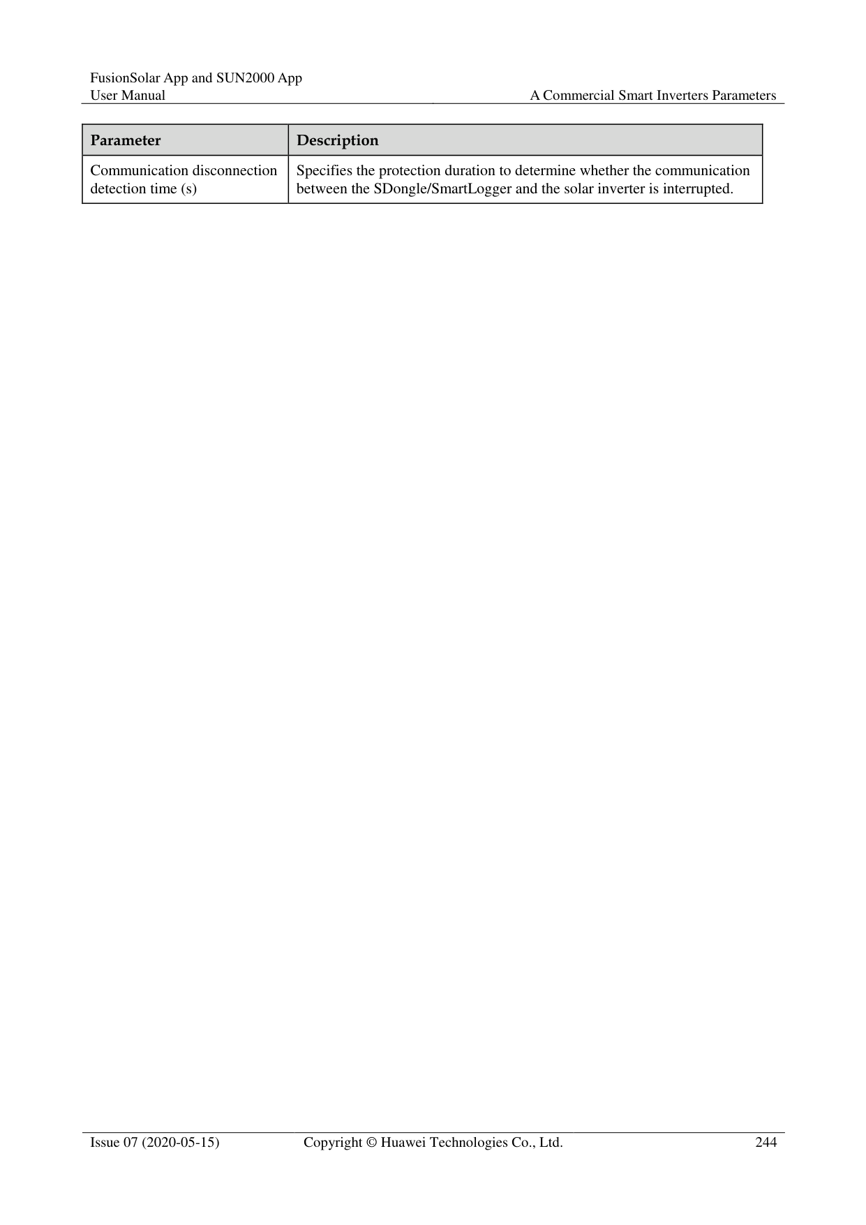
|No.|Parameter|Description|Remarks| |---|---|---|---| |30|Cut-off point of voltage derating (V)|Specifies the stop point for voltage derating.|set to Enable.
When setting this parameter, ensure that the following condition is met: Voltage derating start point < Voltage derating stop point.| |31|Voltage derating cut-off power (V)|Specifies the power threshold for cutting off voltage derating.|set to Enable.
When setting this parameter, ensure that the following condition is met: Voltage derating start point < Voltage derating stop point.| |32|Communication disconnection fail-safe|In the inverter export limitation scenario, if this parameter is set to Enable, the inverter will perform active power derating by percentage when the communication between the inverter and the SmartLogger or Smart Dongle is disconnected for more than the time specified by Communication disconnection detection time.|N/A| |33|Communication disconnection detection time (s)|Specifies the fail-safe detection time for the disconnection between the inverter and the SmartLogger or Smart Dongle.|This parameter is displayed when Communication disconnection fail-safe is set to Enable.
| |34|Active power output limit for fail-safe (%)|Specifies the derating value of the inverter active power by percentage.|This parameter is displayed when Communication disconnection fail-safe is set to Enable.
| |35|Apparent power baseline (kVA)|Adjusts the apparent output baseline of the inverter.|-| |36|Active power baseline (kW)|Adjusts the active output baseline of the inverter.|-| |37|Frequency modulation control|The standards of certain countries and regions require that if the power grid frequency fluctuates around a certain value, the inverter needs to fine-tune the active power output based on Frequency modulation control droop to help stabilize the power grid frequency. In this case, set this parameter to Enable|-| |38|Adjustment ratio of frequency modulation control|Specifies the droop of the active power output.|This parameter is displayed when Frequency modulation control is set to Enable.| |39|Underfrequency rise power|The standards of certain countries and regions require that if the power grid frequency is lower than Frequency for triggering of underfrequency rise power, the inverter needs to increase the active power output to help increase the power grid frequency. In this case, set this parameter to Enable.|-|
|No.|Parameter|Description|Remarks| |---|---|---|---| |40|Frequency for triggering of underfrequency rise power (Hz)|Specifies the frequency threshold of Underfrequency rise power.|This parameter is displayed when Underfrequency rise power is set to Enable.
| |41|Power recovery gradient of underfrequency rise (%/min)|Specifies the recovery rate of Underfrequency rise power.|This parameter is displayed when Underfrequency rise power is set to Enable.
| |42|Cutoff frequency of underfrequency rise power (Hz)|Specifies the cutoff frequency of Underfrequency rise power.|This parameter is displayed when Underfrequency rise power is set to Enable.
| |43|Cutoff power of underfrequency rise power (%)|Specifies the cutoff power of Underfrequency rise power.|This parameter is displayed when Underfrequency rise power is set to Enable.
| |44|Frequency for exiting of underfrequency rise power (Hz)|Specifies the exit frequency of Underfrequency rise power.|This parameter is displayed when Underfrequency rise power is set to Enable.
| |45|Q-U characteristic curve mode|Specifies the reactive power compensation mode of the inverter output.|-| |46|Power percentage for triggering Q-U scheduling|Specifies the reference apparent power, in percentage. When the actual apparent power of the inverter is greater than the value of this parameter, the Q-U characteristic curve scheduling function is enabled.|-| |47|Q-U characteristic curve|The inverter adjusts Q/S (the ratio of the output reactive power to apparent power) in real time based on U/Un(%) (the ratio of the actual power grid voltage to the rated power grid voltage).|-|
|48|Q-P characteristic curve|The inverter adjusts Q/Pn (the ratio of the output reactive power to the rated active power) in real time based on P/Pn(%) (the ratio of the actual active power to the rated active power).|-| |49|Cosφ-P/Pn characteristic curve|The inverter adjusts the output power factor cosφ in real time based on P/Pn(%).|-|
#### A.5 Grid-tied control parameters
######## Special User
Table A-1 Grid-tied control parameters
|Parameter|Description| |---|---| |Active power control mode|Specifies the active power output mode at the grid-tied point.| |Closed-loop controller|Specifies the grid-tied power controller. Before setting the parameter, confirm the controller type. Incorrect setting will result in abnormal power output of the solar inverter. Solar inverter applies only to the scenario where a single solar inverter is used or where a single solar inverter is used with an SDongle.| |Limitation mode|Specifies the active power limitation mode as required by the power grid.| |PV plant capacity (kW)|Specifies the PV array capacity.| |Maximum grid feed-in power (kW)|In Grid connection with limited power (kW) mode, set the maximum power fed to the power grid from the PV array.| |Maximum grid feed-in power (%)|In Grid connection with limited power (%) mode, set the proportion of the maximum power fed to the power grid from the PV array to the capacity of the PV plant.| |Power adjustment period (s)|Specifies the interval for sending adjustment commands.| |Maximum protection time (s)|Specifies the protection duration to determine whether the communication between the external controller and the Smart Power Sensor is interrupted.| |Power control hysteresis (kW)|Specifies the dead zone for adjusting the inverter output power. If the power fluctuation is within the power control hysteresis, the power is not adjusted.| |Fail-safe power threshold (%)|When the communication between the SDongle/SmartLogger, power meter, and solar inverter is interrupted, the solar inverter generates power based on this threshold.| |Reactive power control mode|Specifies the reactive power output mode at the grid-tied point.| |Power factor|Specifies the target power factor of the power meter.| |Adjustment period (s)|Specifies the interval for sending adjustment commands.|
|Adjustment deadband|Specifies the adjustment power factor precision.| |Fail-safe power factor|When the communication between the SDongle/SmartLogger, power meter, and solar inverter is interrupted, the solar inverter generates power based on this threshold.| |Communication disconnection fail-safe|When this parameter is set to Enable, and the communication between the solar inverter and the SDongle/SmartLogger is interrupted for a certain period (set by Communication disconnection detection time), the solar inverter generates power based on Fail-safe power.|
|Parameter|Description| |---|---| |Communication disconnection detection time (s)|Specifies the protection duration to determine whether the communication between the SDongle/SmartLogger and the solar inverter is interrupted.|
B Domain Name List of Management
Systems

The list is subject to change.
Table B-1 Domain names of management systems
|Domain Name|Data Type|Scenario| |---|---|---| |intl.fusionsolar.huawei.com|Public network address|FusionSolar hosting cloud NOTE
Compatible with the former FusionSolar hosting cloud domain name cn.fusionsolar.huawei.com for the Chinese mainland.| |neteco.alsoenergy.com|Public network address|Partner's management system| |re-ene.kyuden.co.jp|Public network address|Remote output control server of Kyushu Electric Power Company| |re-ene.yonden.co.jp|Public network address|Remote output control server of Shikoku Electric Power Company| |eu.fusionsolar.huawei.com|Public network address|Network management system NetEco in Europe| |au1.fusionsolar.huawei.com|Public network address|Network management system NetEco in Australia| |br1.fusionsolar.huawei.com|Public network address|Network management system NetEco in Brazil| |huawei.devicedataacquisitio n.com|Public network address|Third-party network management system Locus dedicated for the United States|
C Acronyms and Abbreviations
A AFCI arc-fault circuit-interrupter APP application
P PID potential induced degradation PV photovoltaic
S SD secure digital memory card