
Ask AI
— answers from the official manualAnswers from the official manual.
Common questions
Common Questions
10 totalHow do I view freeze frame data on the Innova 5610?
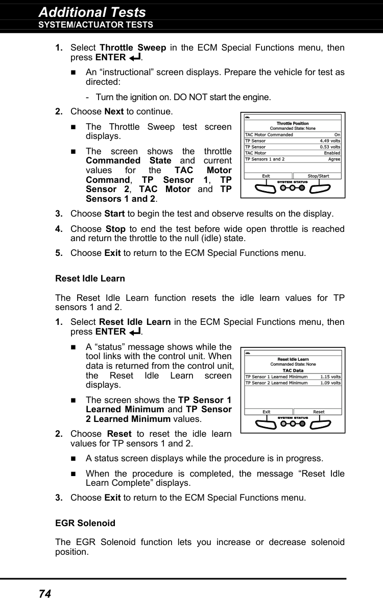
Press the DTC/FF button to display freeze frame data for the priority code (Code #1). Freeze frame is a snapshot of engine conditions at the time the malfunction occurred, including engine speed, open or closed loop operation, fuel system commands, coolant temperature, calculated load value, fuel pressure, vehicle speed, air flow rate, and intake manifold pressure. Only the highest priority code contains freeze frame data.
What safety precautions must I follow when using the Innova 5610?
Always turn the ignition off before connecting or disconnecting the Scan Tool from the vehicle's DLC to prevent damage to the tool and vehicle's electronic components. Operate the vehicle only in a well-ventilated area to avoid carbon monoxide poisoning. Before starting the engine, engage the parking brake, put the transmission in park (automatic) or neutral (manual), and block the drive wheels. Never replace parts based only on DTC definitions; always consult the vehicle's service manual for proper testing procedures.
How do I erase diagnostic trouble codes from the vehicle's computer?
Press the ERASE button on the Scan Tool to erase DTCs and freeze frame data from the vehicle's computer and reset monitor status. However, before erasing codes, always consult the vehicle's service manual for proper testing procedures. DTCs will also be automatically erased after 40 warm-up cycles (80 for fuel and misfire faults) if the fault is not detected again during that period.
What does it mean when the monitor icons are blinking versus solid on the display?
A solid green monitor icon indicates that the associated monitor has completed its diagnostic testing. A blinking or flashing red monitor icon indicates that the vehicle supports that monitor, but the monitor has not yet run its diagnostic testing. All supported monitors must complete their testing for proper vehicle diagnostics.
How do I connect to a vehicle that is not OBD2 compliant using the Innova 5610?
The Innova 5610 can connect to OBD1 vehicles with the purchase of an optional OBD1 Adaptor Kit and OBD1 firmware upgrade. The kit includes connector cable adaptors for Chrysler, Ford, GM, Honda, and Toyota OBD1 Data Link Connectors. These adaptors install on the cable before connecting to the vehicle's OBD1 DLC.
How do I retrieve diagnostic trouble codes from my vehicle using the Innova 5610?
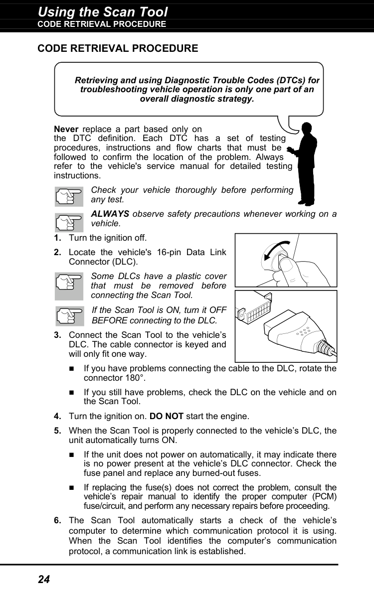
First, turn the ignition off and locate the vehicle's 16-pin Data Link Connector (DLC). Connect the Scan Tool to the DLC (the cable connector is keyed and fits only one way), then turn the ignition on without starting the engine. The Scan Tool will automatically power on and identify the vehicle's communication protocol, establishing a link to retrieve any stored diagnostic trouble codes. After approximately 10-60 seconds, the Scan Tool will display any codes, monitor status, and freeze frame data present in the vehicle's computer.
Show 4 more questions
What do the green, yellow, and red LED indicators on the Innova 5610 mean?
How do I replace the batteries in the Innova 5610 OBD Scanner?
What is the difference between pending and stored diagnostic trouble codes?
What should I do if the Innova 5610 fails to establish communication with the vehicle's computer?
Full Manual
122 pages
Table of Contents
i
Safety Precautions
SAFETY FIRST! ...................................................................... 1Scan Tool Controls
Controls And Indicators .............................................
2Display Functions ...........................................................
4Battery Replacement ....................................................
5Onboard Diagnostics
Computer Engine Controls ........................................
7 DIAGNOSTIC TROUBLE CODES (DTCs) .............................. 12 OBD2 MONITORS .................................................................. 15Using The Scan Tool
Code Retrieval Procedure ......................................... 24
THE SYSTEM MENU .............................................................. 29 VIEWING OEM ENHANCED DTCs (except Ford/Mazda) ....... 29 VIEWING OEM ENHANCED DTCs (Ford/Mazda only) ........... 30 VIEWING ABS DTCs .............................................................. 32 VIEWING SRS DTCs .............................................................. 33 VIEWING TPMS DTCs ........................................................... 34 NETWORK TEST ................................................................... 36 ERASING DIAGNOSTIC TROUBLE CODES (DTCs) ............. 38About Repairsolutions 2® ........................................... 39
Connecting To Bluetooth / Wifi ................................. 40
Live Data Mode
VIEWING LIVE DATA ............................................................. 42 CUSTOMIZING LIVE DATA (PIDs) ......................................... 43Recording (Capturing) Live Data ................................ 44
LIVE DATA PLAYBACK .......................................................... 47Additional Tests
THE MAIN MENU .................................................................... 49System/Actuator Tests ................................................ 50
Performing Service Resets ........................................ 96
Performing A Service Check ...................................... 104
Hybrid Battery Check, Battery Alternator Test 104
SYSTEM TEST MENU ............................................................ 105Battery/Alternator Monitor ..................................... 108
Viewing Drive Cycle Procedures .............................. 111
Using The Dlc Locator ................................................... 112
Viewing Vehicle Information ...................................... 112
Viewing The Firmware Version ................................... 114
THE TOOL LIBRARY .............................................................. 114 TOOL SETTINGS ................................................................... 118Using Scan Tool Memory
Viewing Data In Memory ................................................ 120
Warranty And Servicing
Limited One Year Warranty .......................................... 121
Service Procedures ...................................................... 121
Safety Precautions
Safety First!
1
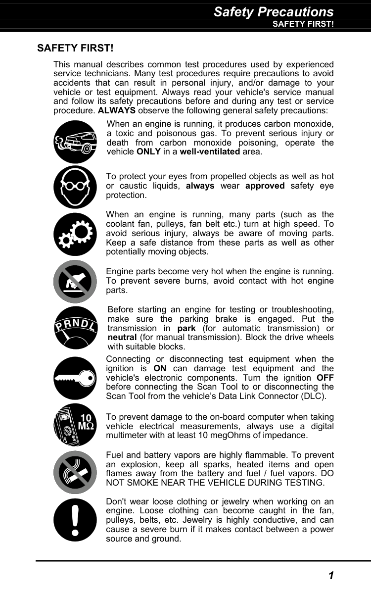
Safety First!
This manual describes common test procedures used by experienced service technicians. Many test procedures require precautions to avoid accidents that can result in personal injury, and/or damage to your vehicle or test equipment. Always read your vehicle's service manual and follow its safety precautions before and during any test or service procedure. ALWAYS observe the following general safety precautions: When an engine is running, it produces carbon monoxide, a toxic and poisonous gas. To prevent serious injury or death from carbon monoxide poisoning, operate the vehicle ONLY in a well-ventilated area. To protect your eyes from propelled objects as well as hot or caustic liquids, always wear approved safety eye protection. When an engine is running, many parts (such as the coolant fan, pulleys, fan belt etc.) turn at high speed. To avoid serious injury, always be aware of moving parts. Keep a safe distance from these parts as well as other potentially moving objects. Engine parts become very hot when the engine is running. To prevent severe burns, avoid contact with hot engine parts. Before starting an engine for testing or troubleshooting, make sure the parking brake is engaged. Put the transmission in park (for automatic transmission) or neutral (for manual transmission). Block the drive wheels with suitable blocks. Connecting or disconnecting test equipment when the ignition is ON can damage test equipment and the vehicle's electronic components. Turn the ignition OFF before connecting the Scan Tool to or disconnecting the Scan Tool from the vehicle’s Data Link Connector (DLC). To prevent damage to the on-board computer when taking vehicle electrical measurements, always use a digital multimeter with at least 10 megOhms of impedance. Fuel and battery vapors are highly flammable. To prevent an explosion, keep all sparks, heated items and open flames away from the battery and fuel / fuel vapors. DONot Smoke Near The Vehicle During Testing.
Don't wear loose clothing or jewelry when working on an engine. Loose clothing can become caught in the fan, pulleys, belts, etc. Jewelry is highly conductive, and can cause a severe burn if it makes contact between a power source and ground.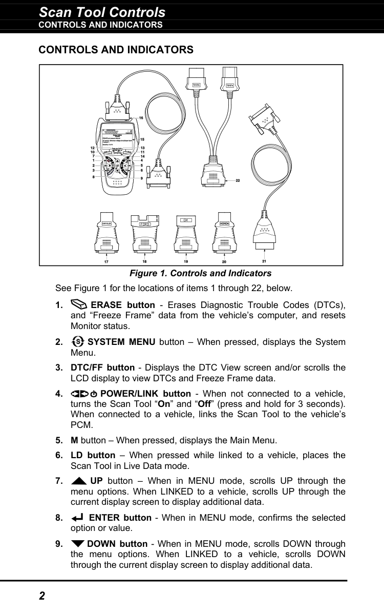
Scan Tool Controls
Controls And Indicators
2
Controls And Indicators
Figure 1. Controls and Indicators See Figure 1 for the locations of items 1 through 22, below.Pcm.
Scan Tool Controls
Controls And Indicators
3
Scan Tool Controls
Display Functions
4
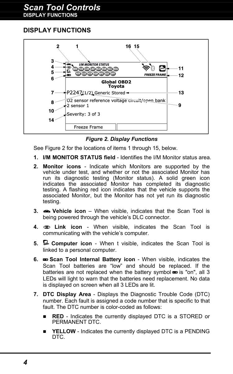
Display Functions
Figure 2. Display Functions See Figure 2 for the locations of items 1 through 15, below.Permanent Dtc.
YELLOW - Indicates the currently displayed DTC is a PENDINGDtc.
Scan Tool Controls
Battery Replacement
5
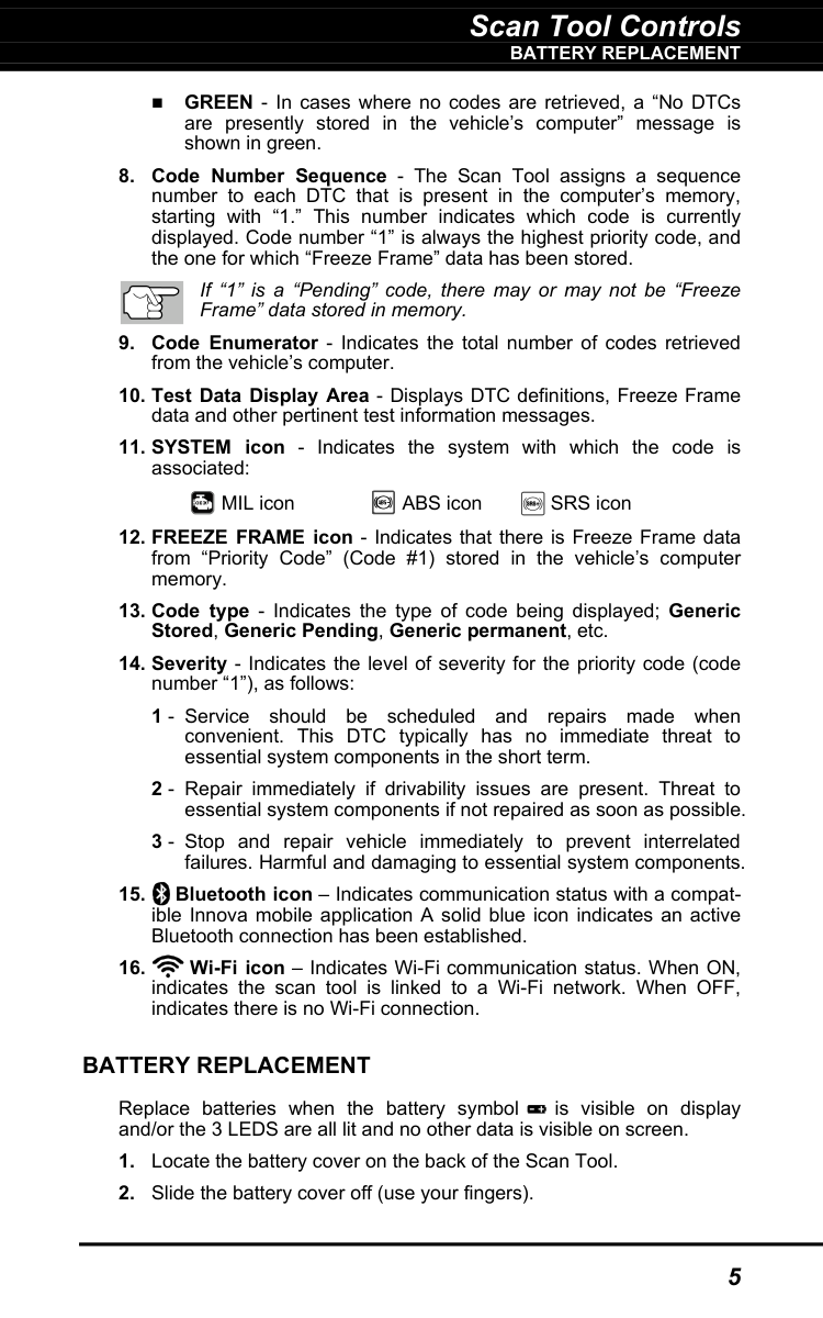
GREEN - In cases where no codes are retrieved, a “No DTCs are presently stored in the vehicle’s computer” message is shown in green.
ABS icon SRS icon
Battery Replacement
Replace batteries when the battery symbol is visible on display and/or the 3 LEDS are all lit and no other data is visible on screen.
Scan Tool Controls
Battery Replacement
6
Onboard Diagnostics
Computer Engine Controls
7
Computer Engine Controls
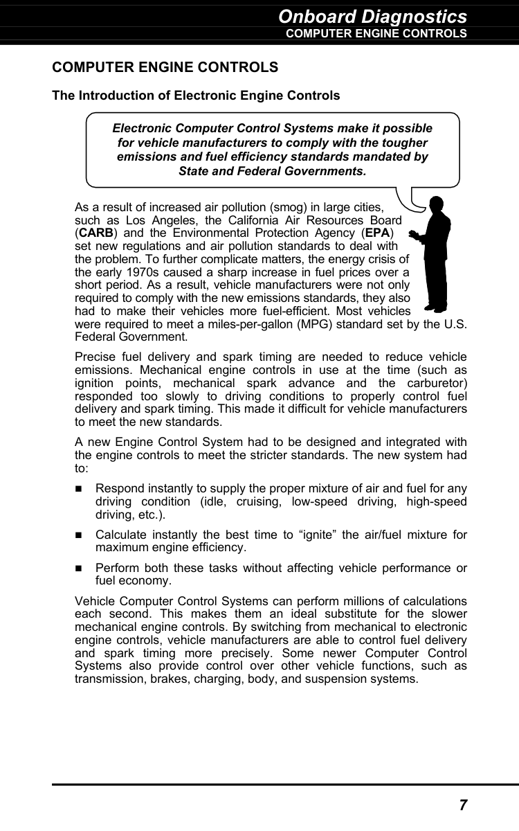
The Introduction of Electronic Engine ControlsAs a result of increased air pollution (smog) in large cities, such as Los Angeles, the California Air Resources Board (CARB) and the Environmental Protection Agency (EPA) set new regulations and air pollution standards to deal with the problem. To further complicate matters, the energy crisis of the early 1970s caused a sharp increase in fuel prices over a short period. As a result, vehicle manufacturers were not only required to comply with the new emissions standards, they also had to make their vehicles more fuel-efficient. Most vehicles were required to meet a miles-per-gallon (MPG) standard set by the U.S. Federal Government. Precise fuel delivery and spark timing are needed to reduce vehicle emissions. Mechanical engine controls in use at the time (such as ignition points, mechanical spark advance and the carburetor) responded too slowly to driving conditions to properly control fuel delivery and spark timing. This made it difficult for vehicle manufacturers to meet the new standards. A new Engine Control System had to be designed and integrated with the engine controls to meet the stricter standards. The new system had to: Respond instantly to supply the proper mixture of air and fuel for any driving condition (idle, cruising, low-speed driving, high-speed driving, etc.). Calculate instantly the best time to “ignite” the air/fuel mixture for maximum engine efficiency. Perform both these tasks without affecting vehicle performance or fuel economy. Vehicle Computer Control Systems can perform millions of calculations each second. This makes them an ideal substitute for the slower mechanical engine controls. By switching from mechanical to electronic engine controls, vehicle manufacturers are able to control fuel delivery and spark timing more precisely. Some newer Computer Control Systems also provide control over other vehicle functions, such as transmission, brakes, charging, body, and suspension systems. Electronic Computer Control Systems make it possible for vehicle manufacturers to comply with the tougher emissions and fuel efficiency standards mandated by State and Federal Governments.
Onboard Diagnostics
Computer Engine Controls
8
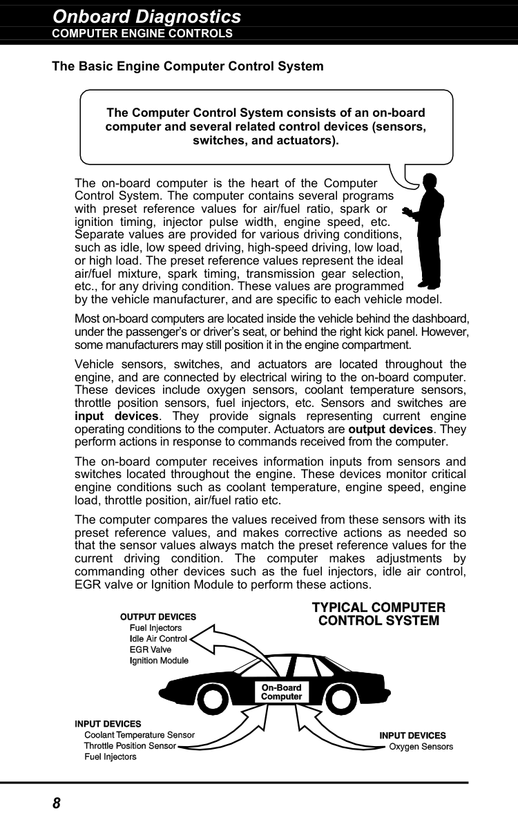
The Basic Engine Computer Control System The on-board computer is the heart of the Computer Control System. The computer contains several programs with preset reference values for air/fuel ratio, spark or ignition timing, injector pulse width, engine speed, etc. Separate values are provided for various driving conditions, such as idle, low speed driving, high-speed driving, low load, or high load. The preset reference values represent the ideal air/fuel mixture, spark timing, transmission gear selection, etc., for any driving condition. These values are programmed by the vehicle manufacturer, and are specific to each vehicle model. Most on-board computers are located inside the vehicle behind the dashboard, under the passenger’s or driver’s seat, or behind the right kick panel. However, some manufacturers may still position it in the engine compartment. Vehicle sensors, switches, and actuators are located throughout the engine, and are connected by electrical wiring to the on-board computer. These devices include oxygen sensors, coolant temperature sensors, throttle position sensors, fuel injectors, etc. Sensors and switches are input devices. They provide signals representing current engine operating conditions to the computer. Actuators are output devices. They perform actions in response to commands received from the computer. The on-board computer receives information inputs from sensors and switches located throughout the engine. These devices monitor critical engine conditions such as coolant temperature, engine speed, engine load, throttle position, air/fuel ratio etc. The computer compares the values received from these sensors with its preset reference values, and makes corrective actions as needed so that the sensor values always match the preset reference values for the current driving condition. The computer makes adjustments by commanding other devices such as the fuel injectors, idle air control, EGR valve or Ignition Module to perform these actions. The Computer Control System consists of an on-board computer and several related control devices (sensors, switches, and actuators).
Onboard Diagnostics
Computer Engine Controls
9
Vehicle operating conditions are constantly changing. The computer continuously makes adjustments or corrections (especially to the air/fuel mixture and spark timing) to keep all the engine systems operating within the preset reference values. On-Board Diagnostics - First Generation (OBD1)
Beginning in 1988, California’s Air Resources Board (CARB), and later the Environmental Protection Agency (EPA) required vehicle manufacturers to include a self-diagnostic program in their on-board computers. The program would be capable of identifying emissions-related faults in a system. The first generation of Onboard Diagnostics came to be known as
Obd1.
OBD1 is a set of self-testing and diagnostic instructions programmed into the vehicle’s on-board computer. The programs are specifically designed to detect failures in the sensors, actuators, switches and wiring of the various vehicle emissions-related systems. If the computer detects a failure in any of these components or systems, it lights an indicator on the dashboard to alert the driver. The indicator lights only when an emissions-related problem is detected. The computer also assigns a numeric code for each specific problem that it detects, and stores these codes in its memory for later retrieval. These codes can be retrieved from the computer’s memory with the use of a “Code Reader” or a “Scan Tool.” On-Board Diagnostics - Second Generation (OBD2) In addition to performing all the functions of the OBD1 System, the OBD2 System has been enhanced with new Diagnostic Programs. These programs closely monitor the functions of various emissions-related compo- nents and systems (as well as other systems) and make this information readily available (with the proper equipment) to the technician for evaluation. The California Air Resources Board (CARB) conducted studies on OBD1 equipped vehicles. The information that was gathered from these studies showed the following: A large number of vehicles had deteriorating or degraded emissions-related components. These components were causing an increase in emissions. With the exception of some 1994 and 1995 vehicles, most vehicles from 1982 to 1995 are equipped with some type of first generation On-Board Diagnostics. The OBD2 System is an enhancement of the OBD1 System.
Onboard Diagnostics
Computer Engine Controls
10
Because OBD1 systems only detect failed components, the degraded components were not setting codes. Some emissions problems related to degraded components only occur when the vehicle is being driven under a load. The emission checks being conducted at the time were not performed under simulated driving conditions. As a result, a significant number of vehicles with degraded components were passing Emissions Tests. Codes, code definitions, diagnostic connectors, communication protocols and emissions terminology were different for each manufacturer. This caused confusion for the technicians working on different make and model vehicles. To address the problems made evident by this study, CARB and the EPA passed new laws and standardization requirements. These laws required that vehicle manufacturers to equip their new vehicles with devices capable of meeting all of the new emissions standards and regulations. It was also decided that an enhanced on-board diagnostic system, capable of addressing all of these problems, was needed. This new system is known as “On-Board Diagnostics Generation Two (OBD2).” The primary objective of the OBD2 system is to comply with the latest regulations and emissions standards established by CARB and the EPA. The Main Objectives of the OBD2 System are: To detect degraded and/or failed emissions-related components or systems that could cause tailpipe emissions to exceed by 1.5 times the Federal Test Procedure (FTP) standard. To expand emissions-related system monitoring. This includes a set of computer run diagnostics called Monitors. Monitors perform diagnostics and testing to verify that all emissions-related components and/or systems are operating correctly and within the manufacturer’s specifications. To use a standardized Diagnostic Link Connector (DLC) in all vehicles. (Before OBD2, DLCs were of different shapes and sizes.) To standardize the code numbers, code definitions and language used to describe faults. (Before OBD2, each vehicle manufacturer used their own code numbers, code definitions and language to describe the same faults.) To expand the operation of the Malfunction Indicator Lamp (MIL). To standardize communication procedures and protocols between the diagnostic equipment (Scan Tools, Code Readers, etc.) and the vehicle’s on-board computer. OBD2 Terminology The following terms and their definitions are related to OBD2 systems. Read and reference this list as needed to aid in the understanding of OBD2 systems.
Onboard Diagnostics
Computer Engine Controls
11
Powertrain Control Module (PCM) - The PCM is the OBD2 accepted term for the vehicle’s “on-board computer.” In addition to controlling the engine management and emissions systems, the PCM also participates in controlling the powertrain (transmission) operation. Most PCMs also have the ability to communicate with other computers on the vehicle (ABS, ride control, body, etc.). Monitor - Monitors are “diagnostic routines” programmed into the PCM. The PCM utilizes these programs to run diagnostic tests, and to monitor operation of the vehicle’s emissions-related components or systems to ensure they are operating correctly and within the vehicle’s manufacturer specifications. Currently, up to fifteen Monitors are used in OBD2 systems. Additional Monitors will be added as the OBD2 system is further developed. Not all vehicles support all fifteen Monitors. Enabling Criteria - Each Monitor is designed to test and monitor the operation of a specific part of the vehicle’s emissions system (EGR system, oxygen sensor, catalytic converter, etc.). A specific set of “conditions” or “driving procedures” must be met before the computer can command a Monitor to run tests on its related system. These “conditions” are known as “Enabling Criteria.” The requirements and procedures vary for each Monitor. Some Monitors only require the ignition key to be turned “On” for them to run and complete their diagnostic testing. Others may require a set of complex procedures, such as, starting the vehicle when cold, bringing it to operating temperature, and driving the vehicle under specific conditions before the Monitor can run and complete its diagnostic testing. Monitor Has/Has Not Run - The terms “Monitor has run” or “Monitor has not run” are used throughout this manual. “Monitor has run,” means the PCM has commanded a particular Monitor to perform the required diagnostic testing on a system to ensure the system is operating correctly (within factory specifications). The term “Monitor has not run” means the PCM has not yet commanded a particular Monitor to perform diagnostic testing on its associated part of the emissions system. Trip - A Trip for a particular Monitor requires that the vehicle is being driven in such a way that all the required “Enabling Criteria” for the Monitor to run and complete its diagnostic testing are met. The “Trip Drive Cycle” for a particular Monitor begins when the ignition key is turned “On.” It is successfully completed when all the “Enabling Criteria” for the Monitor to run and complete its diagnostic testing are met by the time the ignition key is turned “Off.” Since each of the fifteen monitors is designed to run diagnostics and testing on a different part of the engine or emissions system, the “Trip Drive Cycle” needed for each individual Monitor to run and complete varies.
Onboard Diagnostics
DIAGNOSTIC TROUBLE CODES (DTCs)
12
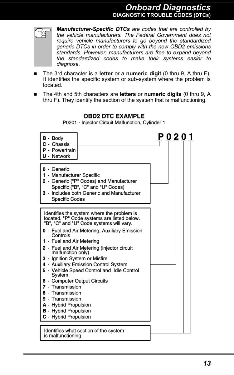
OBD2 Drive Cycle - An OBD2 Drive Cycle is an extended set of driving procedures that takes into consideration the various types of driving conditions encountered in real life. These conditions may include starting the vehicle when it is cold, driving the vehicle at a steady speed (cruising), accelerating, etc. An OBD2 Drive Cycle begins when the ignition key is turned “On” (when cold) and ends when the vehicle has been driven in such a way as to have all the “Enabling Criteria” met for all its applicable Monitors. Only those trips that provide the Enabling Criteria for all Monitors applicable to the vehicle to run and complete their individual diagnostic tests qualify as an OBD2 Drive Cycle. OBD2 Drive Cycle requirements vary from one model of vehicle to another. Vehicle manufacturers set these procedures. Consult your vehicle’s service manual for OBD2 Drive Cycle procedures. Do not confuse a “Trip” Drive Cycle with an OBD2 Drive Cycle. A “Trip” Drive Cycle provides the “Enabling Criteria” for one specific Monitor to run and complete its diagnostic testing. An OBD2 Drive Cycle must meet the “Enabling Criteria” for all Monitors on a particular vehicle to run and complete their diagnostic testing. Warm-up Cycle - Vehicle operation after an engine off period where engine temperature rises at least 40°F (22°C) from its temperature before starting, and reaches at least 160°F (70°C). The PCM uses warm-up cycles as a counter to automatically erase a specific code and related data from its memory. When no faults related to the original problem are detected within a specified number of warm-up cycles, the code is erased automatically. DIAGNOSTIC TROUBLE CODES (DTCs) Diagnostic Trouble Codes (DTCs) are meant to guide you to the proper service procedure in the vehicle’s service manual. DO NOT replace parts based only on DTCs without first consulting the vehicle’s service manual for proper testing procedures for that particular system, circuit or component. DTCs are alphanumeric codes that are used to identify a problem that is present in any of the systems that are monitored by the on-board computer (PCM). Each trouble code has an assigned message that identifies the circuit, component or system area where the problem was found. OBD2 diagnostic trouble codes are made up of five characters: The 1st character is a letter (B, C, P or U). It identifies the “main system” where the fault occurred (Body, Chassis, Powertrain, or Network). The 2nd character is a numeric digit (0 thru 3). It identifies the “type” of code (Generic or Manufacturer-Specific). Generic DTCs are codes that are used by all vehicle manu- facturers. The standards for generic DTCs, as well as their definitions, are set by the Society of Automotive Engineers (SAE). Diagnostic Trouble Codes (DTCs) are codes that identify a specific problem area.
Onboard Diagnostics
DIAGNOSTIC TROUBLE CODES (DTCs)
13
Manufacturer-Specific DTCs are codes that are controlled by the vehicle manufacturers. The Federal Government does not require vehicle manufacturers to go beyond the standardized generic DTCs in order to comply with the new OBD2 emissions standards. However, manufacturers are free to expand beyond the standardized codes to make their systems easier to diagnose. The 3rd character is a letter or a numeric digit (0 thru 9, A thru F). It identifies the specific system or sub-system where the problem is located. The 4th and 5th characters are letters or numeric digits (0 thru 9, A thru F). They identify the section of the system that is malfunctioning.
Onboard Diagnostics
DIAGNOSTIC TROUBLE CODES (DTCs)
14
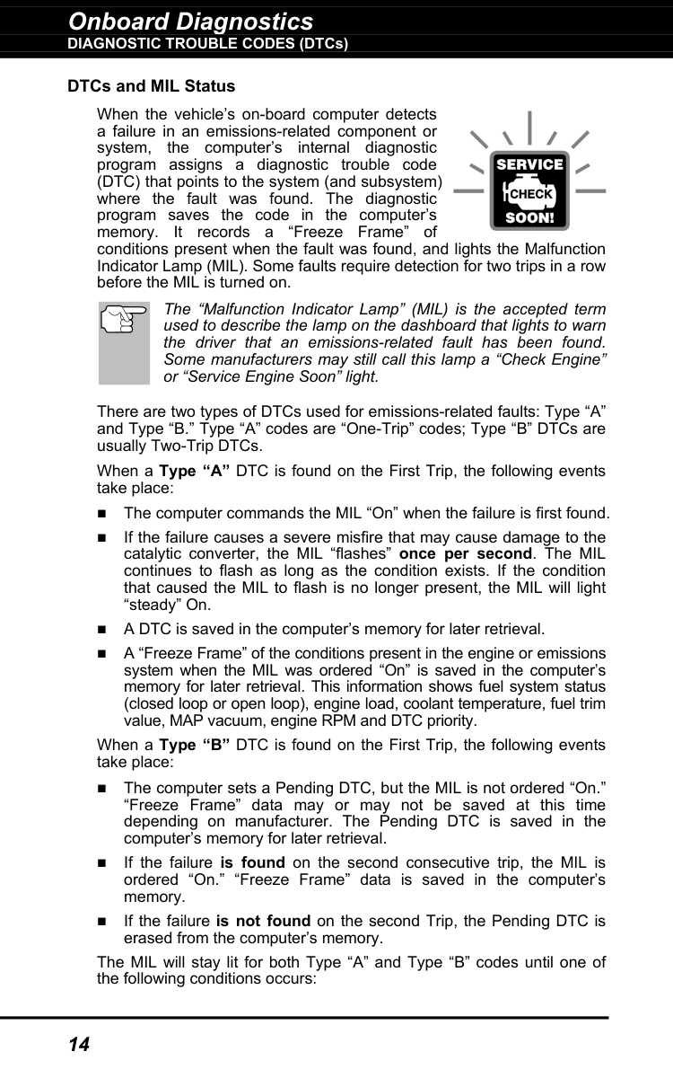
DTCs and MIL Status When the vehicle’s on-board computer detects a failure in an emissions-related component or system, the computer’s internal diagnostic program assigns a diagnostic trouble code (DTC) that points to the system (and subsystem) where the fault was found. The diagnostic program saves the code in the computer’s memory. It records a “Freeze Frame” of conditions present when the fault was found, and lights the Malfunction Indicator Lamp (MIL). Some faults require detection for two trips in a row before the MIL is turned on. The “Malfunction Indicator Lamp” (MIL) is the accepted term used to describe the lamp on the dashboard that lights to warn the driver that an emissions-related fault has been found. Some manufacturers may still call this lamp a “Check Engine” or “Service Engine Soon” light. There are two types of DTCs used for emissions-related faults: Type “A” and Type “B.” Type “A” codes are “One-Trip” codes; Type “B” DTCs are usually Two-Trip DTCs. When a Type “A” DTC is found on the First Trip, the following events take place: The computer commands the MIL “On” when the failure is first found. If the failure causes a severe misfire that may cause damage to the catalytic converter, the MIL “flashes” once per second. The MIL continues to flash as long as the condition exists. If the condition that caused the MIL to flash is no longer present, the MIL will light “steady” On. A DTC is saved in the computer’s memory for later retrieval. A “Freeze Frame” of the conditions present in the engine or emissions system when the MIL was ordered “On” is saved in the computer’s memory for later retrieval. This information shows fuel system status (closed loop or open loop), engine load, coolant temperature, fuel trim value, MAP vacuum, engine RPM and DTC priority. When a Type “B” DTC is found on the First Trip, the following events take place: The computer sets a Pending DTC, but the MIL is not ordered “On.” “Freeze Frame” data may or may not be saved at this time depending on manufacturer. The Pending DTC is saved in the computer’s memory for later retrieval. If the failure is found on the second consecutive trip, the MIL is ordered “On.” “Freeze Frame” data is saved in the computer’s memory. If the failure is not found on the second Trip, the Pending DTC is erased from the computer’s memory. The MIL will stay lit for both Type “A” and Type “B” codes until one of the following conditions occurs:
Onboard Diagnostics
Obd2 Monitors
15
If the conditions that caused the MIL to light are no longer present for the next three trips in a row, the computer automatically turns the MIL “Off” if no other emissions-related faults are present. However, the DTCs remain in the computer’s memory as a history code for 40 warm-up cycles (80 warm-up cycles for fuel and misfire faults). The DTCs are automatically erased if the fault that caused them to be set is not detected again during that period. Misfire and fuel system faults require three trips with “similar conditions” before the MIL is turned “Off.” These are trips where the engine load, RPM and temperature are similar to the conditions present when the fault was first found. After the MIL has been turned off, DTCs and Freeze Frame data stay in the computer’s memory. Erasing the DTCs from the computer’s memory can also turn off the MIL. See ERASING DIAGNOSTIC TROUBLE CODES (DTCs) on page 38, before erasing codes from the computer’s memory. If a Diagnostic Tool or Scan Tool is used to erase the codes, Freeze Frame data will also be erased.
Obd2 Monitors
To ensure the correct operation of the various emissions-related components and systems, a diagnostic program was developed and installed in the vehicle’s on-board computer. The program has several procedures and diagnostic strategies. Each procedure or diagnostic strategy is made to monitor the operation of, and run diagnostic tests on, a specific emissions-related component or system. These tests ensure the system is running correctly and is within the manufacturer’s specifications. On OBD2 systems, these procedures and diagnostic strategies are called “Monitors.” Currently, fifteen Monitors are supported by OBD2 systems. Additional monitors may be added as a result of Government regulations as the OBD2 system grows and matures. Not all vehicles support all fifteen Monitors. Additionally, some Monitors are supported by “spark ignition” vehicles only, while others are supported by “compression ignition” vehicles only. Monitor operation is either “Continuous” or “Non-Continuous,” depending on the specific monitor. Continuous Monitors Three of these Monitors are designed to constantly monitor their associated components and/or systems for proper operation. Continuous Monitors run constantly when the engine is running. The Continuous Monitors are: Comprehensive Component Monitor (CCM) Misfire Monitor Fuel System Monitor
Onboard Diagnostics
Obd2 Monitors
16
Non-Continuous Monitors The other twelve Monitors are “non-continuous” Monitors. “Non- continuous” Monitors perform and complete their testing once per trip. The “non-continuous” Monitors are: Oxygen Sensor Monitor Oxygen Sensor Heater Monitor Catalyst Monitor Heated Catalyst Monitor EGR System Monitor EVAP System Monitor Secondary Air System Monitor The following Monitors became standard beginning in 2010. The majority of vehicles produced before this time will not support these Monitors NMHC Monitor NOx Adsorber Monitor Boost Pressure System Monitor Exhaust Gas Sensor Monitor PM Filter Monitor The following provides a brief explanation of the function of each Monitor: Comprehensive Component Monitor (CCM) - This Monitor continuously checks all inputs and outputs from sensors, actuators, switches and other devices that provide a signal to the computer. The Monitor checks for shorts, opens, out of range value, functionality and “rationality.” Rationality: Each input signal is compared against all other inputs and against information in the computer’s memory to see if it makes sense under the current operating conditions. Example: The signal from the throttle position sensor indicates the vehicle is in a wide-open throttle condition, but the vehicle is really at idle, and the idle condition is confirmed by the signals from all other sensors. Based on the input data, the computer determines that the signal from the throttle position sensor is not rational (does not make sense when compared to the other inputs). In this case, the signal would fail the rationality test. The CCM is supported by both “spark ignition” vehicles and “compression ignition” vehicles. The CCM may be either a “One-Trip” or a “Two-Trip” Monitor, depending on the component.
Onboard Diagnostics
Obd2 Monitors
17
Fuel System Monitor - This Monitor uses a Fuel System Correction program, called Fuel Trim, inside the on-board computer. Fuel Trim is a set of positive and negative values that represent adding or subtracting fuel from the engine. This program is used to correct for a lean (too much air/not enough fuel) or rich (too much fuel/not enough air) air-fuel mixture. The program is designed to add or subtract fuel, as needed, up to a certain percent. If the correction needed is too large and exceeds the time and percent allowed by the program, a fault is indicated by the computer. The Fuel System Monitor is supported by both “spark ignition” vehicles and “compression ignition” vehicles. The Fuel System Monitor may be a “One-Trip” or “Two-Trip” Monitor, depending on the severity of the problem. Misfire Monitor - This Monitor continuously checks for engine misfires. A misfire occurs when the air-fuel mixture in the cylinder does not ignite. The misfire Monitor uses changes in crankshaft speed to sense an engine misfire. When a cylinder misfires, it no longer contributes to the speed of the engine, and engine speed decreases each time the affected cylinder(s) misfire. The misfire Monitor is designed to sense engine speed fluctuations and determine from which cylinder(s) the misfire is coming, as well as how bad the misfire is. There are three types of engine misfires, Types 1, 2, and 3.
Onboard Diagnostics
Obd2 Monitors
18
the downstream sensor signal voltage becomes almost the same as the upstream sensor signal. In this case, the monitor fails the test. The Catalyst Monitor is supported by “spark ignition” vehicles only. The Catalyst Monitor is a “Two-Trip” Monitor. If a fault is found on the first trip, the computer temporarily saves the fault in its memory as a Pending Code. The computer does not command the MIL on at this time. If the fault is sensed again on the second trip, the computer commands the MIL “On” and saves the code in its long-term memory. Heated Catalyst Monitor - Operation of the “heated” catalytic converter is similar to the catalytic converter. The main difference is that a heater is added to bring the catalytic converter to its operating temperature more quickly. This helps reduce emissions by reducing the converter’s down time when the engine is cold. The Heated Catalyst Monitor performs the same diagnostic tests as the catalyst Monitor, and also tests the catalytic converter’s heater for proper operation. The Heated Catalyst Monitor is supported by “spark ignition” vehicles only. This Monitor is also a “Two-Trip” Monitor. Exhaust Gas Recirculation (EGR) Monitor - The Exhaust Gas Recirculation (EGR) system helps reduce the formation of Oxides of Nitrogen during combustion. Temperatures above 2500°F cause nitrogen and oxygen to combine and form Oxides of Nitrogen in the combustion chamber. To reduce the formation of Oxides of Nitrogen, combustion temperatures must be kept below 2500°F. The EGR system recirculates small amounts of exhaust gas back into the intake manifold, where it is mixed with the incoming air/fuel mixture. This reduces combustion temperatures by up to 500°F. The computer determines when, for how long, and how much exhaust gas is recirculated back to the intake manifold. The EGR Monitor performs EGR system function tests at preset times during vehicle operation. The EGR Monitor is supported by both “spark ignition” vehicles and “compression ignition” vehicles. The EGR Monitor is a “Two-Trip” Monitor. If a fault is found on the first trip, the computer temporarily saves the fault in its memory as a Pending Code. The computer does not command the MIL on at this time. If the fault is sensed again on the second trip, the computer commands the MIL “On,” and saves the code in its long-term memory. Evaporative System (EVAP) Monitor - OBD2 vehicles are equipped with a fuel Evaporative system (EVAP) that helps prevent fuel vapors from evaporating into the air. The EVAP system carries fumes from the fuel tank to the engine where they are burned during combustion. The EVAP system may consist of a charcoal canister, fuel tank cap, purge solenoid, vent solenoid, flow monitor, leak detector and connecting tubes, lines and hoses. Fumes are carried from the fuel tank to the charcoal canister by hoses or tubes. The fumes are stored in the charcoal canister. The computer controls the flow of fuel vapors from the charcoal canister to the engine via a purge solenoid. The computer energizes or de-energizes the purge solenoid (depending on solenoid design). The purge solenoid opens a
Onboard Diagnostics
Obd2 Monitors
19
valve to allow engine vacuum to draw the fuel vapors from the canister into the engine where the vapors are burned. The EVAP Monitor checks for proper fuel vapor flow to the engine, and pressurizes the system to test for leaks. The computer runs this Monitor once per trip. The EVAP Monitor is supported by “spark ignition” vehicles only. The EVAP Monitor is a “Two-Trip” Monitor. If a fault is found on the first trip, the computer temporarily saves the fault in its memory as a Pending Code. The computer does not command the MIL on at this time. If the fault is sensed again on the second trip, the PCM commands the MIL “On,” and saves the code in its long-term memory. Oxygen Sensor Heater Monitor - The Oxygen Sensor Heater Monitor tests the operation of the oxygen sensor’s heater. There are two modes of operation on a computer-controlled vehicle: “open- loop” and “closed-loop.” The vehicle operates in open-loop when the engine is cold, before it reaches normal operating temperature. The vehicle also goes to open-loop mode at other times, such as heavy load and full throttle conditions. When the vehicle is running in open-loop, the oxygen sensor signal is ignored by the computer for air/fuel mixture corrections. Engine efficiency during open-loop operation is very low, and results in the production of more vehicle emissions. Closed-loop operation is the best condition for both vehicle emissions and vehicle operation. When the vehicle is operating in closed-loop, the computer uses the oxygen sensor signal for air/fuel mixture corrections. In order for the computer to enter closed-loop operation, the oxygen sensor must reach a temperature of at least 600°F. The oxygen sensor heater helps the oxygen sensor reach and maintain its minimum operating temperature (600°F) more quickly, to bring the vehicle into closed-loop operation as soon as possible. The Oxygen Sensor Heater Monitor is supported by “spark ignition” vehicles only. The Oxygen Sensor Heater Monitor is a “Two-Trip” Monitor. If a fault is found on the first trip, the computer temporarily saves the fault in its memory as a Pending Code. The computer does not command the MIL on at this time. If the fault is sensed again on the second trip, the computer commands the MIL “On,” and saves the code in its long-term memory. Oxygen Sensor Monitor - The Oxygen Sensor monitors how much oxygen is in the vehicle’s exhaust. It generates a varying voltage of up to one volt, based on how much oxygen is in the exhaust gas, and sends the signal to the computer. The computer uses this signal to make corrections to the air/fuel mixture. If the exhaust gas has a large amount of oxygen (a lean air/fuel mixture), the oxygen sensor generates a “low” voltage signal. If the exhaust gas has very little oxygen (a rich mixture condition), the oxygen sensor generates a “high” voltage signal. A 450mV signal indicates the most efficient, and least polluting, air/fuel ratio of 14.7 parts of air to one part of fuel. The oxygen sensor must reach a temperature of at least 600-650°F, and the engine must reach normal operating temperature, for the computer to enter into closed-loop operation. The oxygen sensor only functions when the computer is in closed-loop. A properly operating
Onboard Diagnostics
Obd2 Monitors
20
oxygen sensor reacts quickly to any change in oxygen content in the exhaust stream. A faulty oxygen sensor reacts slowly, or its voltage signal is weak or missing. The Oxygen Sensor Monitor is supported by “spark ignition” vehicles only. The Oxygen Sensor Monitor is a “Two-Trip” monitor. If a fault is found on the first trip, the computer temporarily saves the fault in its memory as a Pending Code. The computer does not command the MIL on at this time. If the fault is sensed again on the second trip, the computer commands the MIL “On,” and saves the code in its long-term memory. Secondary Air System Monitor - When a cold engine is first started, it runs in open-loop mode. During open-loop operation, the engine usually runs rich. A vehicle running rich wastes fuel and creates increased emissions, such as carbon monoxide and some hydrocarbons. A Secondary Air System injects air into the exhaust stream to aid catalytic converter operation:
Onboard Diagnostics
Obd2 Monitors
21
NOx Aftertreatment Monitor - NOx aftertreatment is based on a catalytic converter support that has been coated with a special washcoat containing zeolites. NOx Aftertreatment is designed to reduce oxides of nitrogen emitted in the exhaust stream. The zeolite acts as a molecular "sponge" to trap the NO and NO2 molecules in the exhaust stream. In some implementations, injection of a reactant before the aftertreatment purges it. NO2 in particular is unstable, and will join with hydrocarbons to produce H2O and N2. The NOx Aftertreatment Monitor monitors the function of the NOx aftertreatment to ensure that tailpipe emissions remain within acceptable limits. The NOx Aftertreatment Monitor is supported by “compression ignition” vehicles only. The NOx Aftertreatment Monitor is a “Two-Trip” Monitor. If a fault is found on the first trip, the computer temporarily saves the fault in its memory as a Pending Code. The computer does not command the MIL on at this time. If the fault is sensed again on the second trip, the computer commands the MIL “On,” and saves the code in its long-term memory. Boost Pressure System Monitor - The boost pressure system serves to increase the pressure produced inside the intake manifold to a level greater than atmospheric pressure. This increase in pressure helps to ensure compete combustion of the air-fuel mixture. The Boost Pressure System Monitor checks for component integrity and system operation, and tests for faults in the system. The computer runs this Monitor once per trip. The Boost Pressure System Monitor is supported by “compression ignition” vehicles only. The Boost Pressure System Monitor is a “Two- Trip” Monitor. If a fault is found on the first trip, the computer temporarily saves the fault in its memory as a Pending Code. The computer does not command the MIL on at this time. If the fault is sensed again on the second trip, the computer commands the MIL “On,” and saves the code in its long-term memory. Exhaust Gas Sensor Monitor - The exhaust gas sensor is used by a number of systems/monitors to determine the content of the exhaust stream. The computer checks for component integrity, system operation, and tests for faults in the system, as well as feedback faults that may affect other emission control systems. The Exhaust Gas Sensor Monitor is supported by “compression ignition” vehicles only. The Exhaust Gas Sensor Monitor is a “Two-Trip” Monitor. If a fault is found on the first trip, the computer temporarily saves the fault in its memory as a Pending Code. The computer does not command the MIL on at this time. If the fault is sensed again on the second trip, the computer commands the MIL “On,” and saves the code in its long-term memory.
Onboard Diagnostics
Obd2 Monitors
22
PM Filter Monitor - The particulate matter (PM) filter removes particulate matter from the exhaust stream by filtration. The filter has a honeycomb structure similar to a catalyst substrate, but with the channels blocked at alternate ends. This forces the exhaust gas to flow through the walls between the channels, filtering the particulate matter out. The filters are self-cleaning by periodic modification of the exhaust gas concentration in order to burn off the trapped particles (oxidizing the particles to form CO2 and water). The computer monitors the efficiency of the filter in trapping particulate matter, as well as the ability of the filter to regenerate (self-clean). The PM Filter Monitor is supported by “compression ignition” vehicles only. The PM Filter Monitor is a “Two-Trip” Monitor. If a fault is found on the first trip, the computer temporarily saves the fault in its memory as a Pending Code. The computer does not command the MIL on at this time. If the fault is sensed again on the second trip, the computer commands the MIL “On,” and saves the code in its long-term memory. OBD2 Reference Table The table below lists current OBD2 Monitors, and indicates the following for each Monitor:
A.
Monitor Type (how often does the Monitor run; Continuous or Once per trip)B.
Number of trips needed, with a fault present, to set a pending DTCC.
Number of consecutive trips needed, with a fault present, to command the MIL “On” and store a DTCD.
Number of trips needed, with no faults present, to erase a PendingDtc
E.
Number and type of trips or drive cycles needed, with no faults present, to turn off the MILF.
Number of warm-up periods needed to erase the DTC from the computer’s memory after the MIL is turned off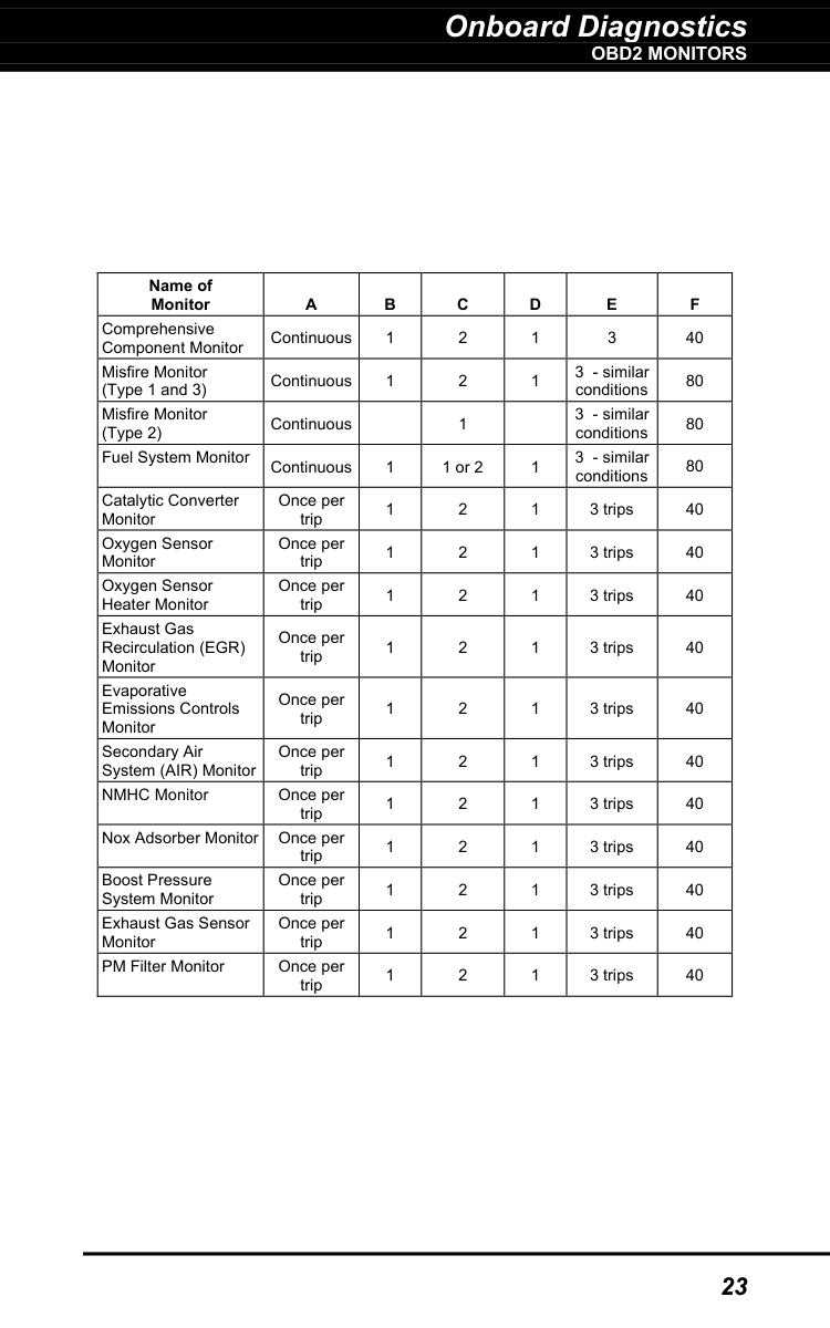
Onboard Diagnostics
Obd2 Monitors
23
Name of Monitor
A
B
C
D
E
F
Comprehensive Component Monitor Continuous 1 2 1 3 40 Misfire Monitor (Type 1 and 3) Continuous 1 2 1 3 - similar conditions 80 Misfire Monitor (Type 2) Continuous1
3 - similar conditions 80 Fuel System Monitor Continuous 1 1 or 2 1 3 - similar conditions 80 Catalytic Converter Monitor Once per trip 1 2 1 3 trips 40 Oxygen Sensor Monitor Once per trip 1 2 1 3 trips 40 Oxygen Sensor Heater Monitor Once per trip 1 2 1 3 trips 40 Exhaust Gas Recirculation (EGR) Monitor Once per trip 1 2 1 3 trips 40 Evaporative Emissions Controls Monitor Once per trip 1 2 1 3 trips 40 Secondary Air System (AIR) Monitor Once per trip 1 2 1 3 trips 40 NMHC Monitor Once per trip 1 2 1 3 trips 40 Nox Adsorber Monitor Once per trip 1 2 1 3 trips 40 Boost Pressure System Monitor Once per trip 1 2 1 3 trips 40 Exhaust Gas Sensor Monitor Once per trip 1 2 1 3 trips 40 PM Filter Monitor Once per trip 1 2 1 3 trips 40
Using the Scan Tool
Code Retrieval Procedure
24
Retrieving and using Diagnostic Trouble Codes (DTCs) for troubleshooting vehicle operation is only one part of an overall diagnostic strategy.
Code Retrieval Procedure
Never replace a part based only on the DTC definition. Each DTC has a set of testing procedures, instructions and flow charts that must be followed to confirm the location of the problem. Always refer to the vehicle's service manual for detailed testing instructions. Check your vehicle thoroughly before performing any test. ALWAYS observe safety precautions whenever working on a vehicle.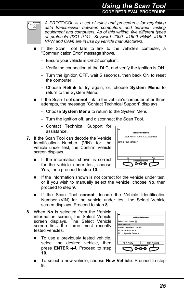
Using the Scan Tool
Code Retrieval Procedure
25
A PROTOCOL is a set of rules and procedures for regulating data transmission between computers, and between testing equipment and computers. As of this writing, five different types of protocols (ISO 9141, Keyword 2000, J1850 PWM, J1850 VPW and CAN) are in use by vehicle manufacturers. If the Scan Tool fails to link to the vehicle’s computer, a “Communication Error” message shows.
Using the Scan Tool
Code Retrieval Procedure
26
Using the Scan Tool
Code Retrieval Procedure
27
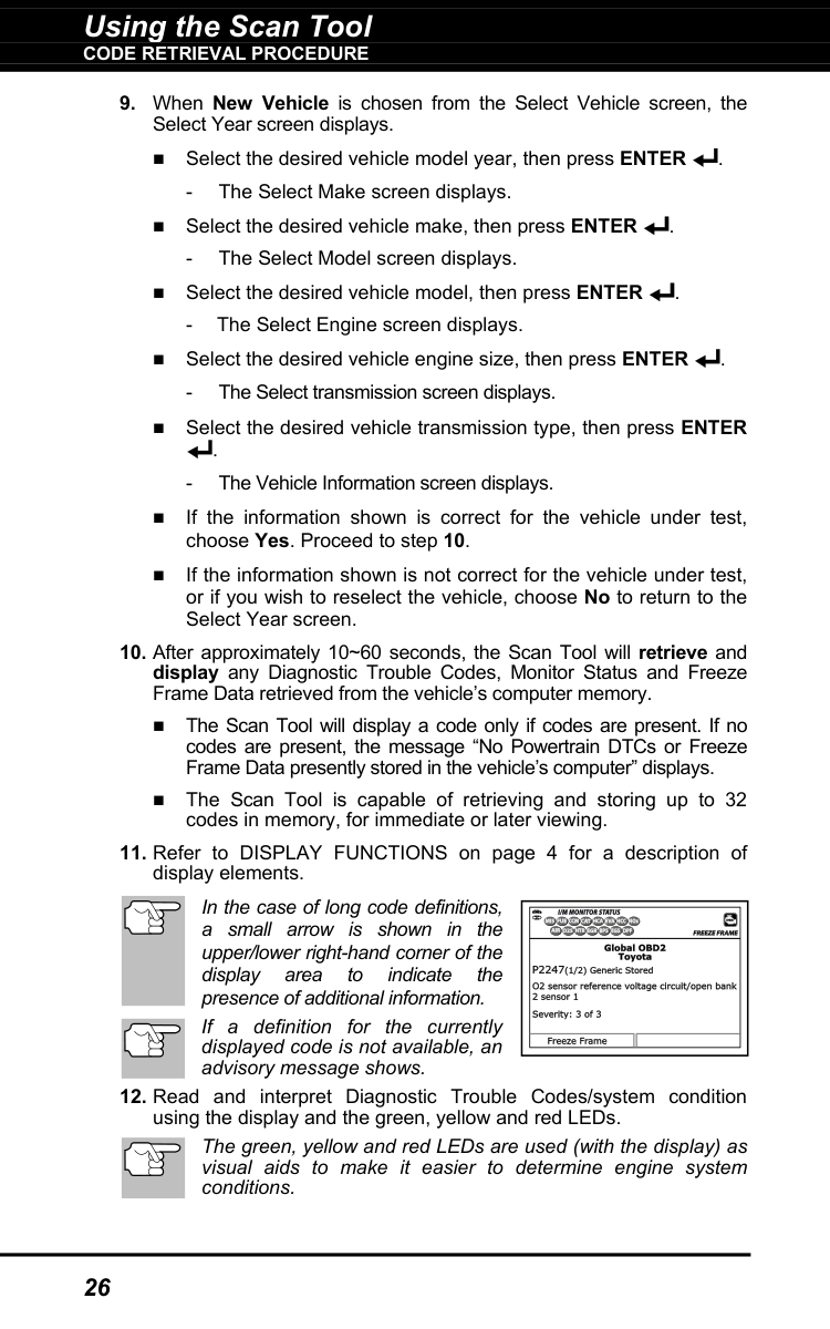
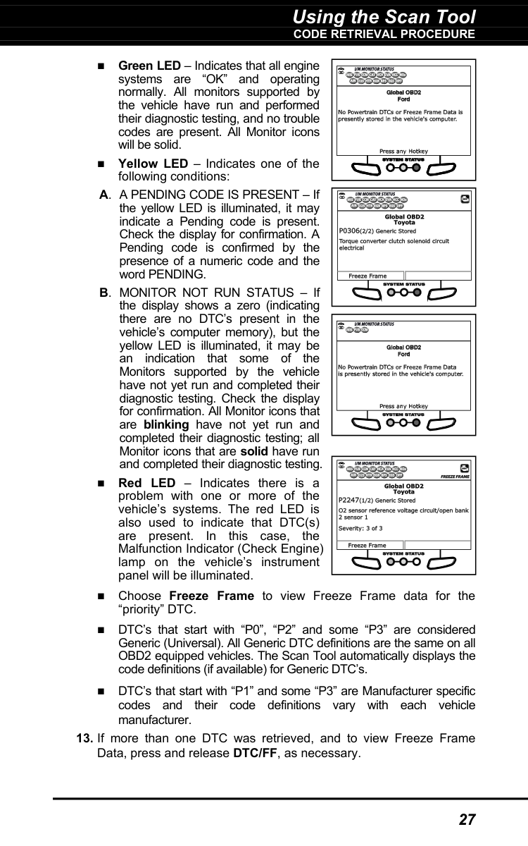
Green LED – Indicates that all engine systems are “OK” and operating normally. All monitors supported by the vehicle have run and performed their diagnostic testing, and no trouble codes are present. All Monitor icons will be solid. Yellow LED – Indicates one of the following conditions: A. A PENDING CODE IS PRESENT – If the yellow LED is illuminated, it may indicate a Pending code is present. Check the display for confirmation. A Pending code is confirmed by the presence of a numeric code and the word PENDING. B. MONITOR NOT RUN STATUS – If the display shows a zero (indicating there are no DTC’s present in the vehicle’s computer memory), but the yellow LED is illuminated, it may be an indication that some of the Monitors supported by the vehicle have not yet run and completed their diagnostic testing. Check the display for confirmation. All Monitor icons that are blinking have not yet run and completed their diagnostic testing; all Monitor icons that are solid have run and completed their diagnostic testing. Red LED – Indicates there is a problem with one or more of the vehicle’s systems. The red LED is also used to indicate that DTC(s) are present. In this case, the Malfunction Indicator (Check Engine) lamp on the vehicle’s instrument panel will be illuminated. Choose Freeze Frame to view Freeze Frame data for the “priority” DTC. DTC’s that start with “P0”, “P2” and some “P3” are considered Generic (Universal). All Generic DTC definitions are the same on all OBD2 equipped vehicles. The Scan Tool automatically displays the code definitions (if available) for Generic DTC’s. DTC’s that start with “P1” and some “P3” are Manufacturer specific codes and their code definitions vary with each vehicle manufacturer.
Using the Scan Tool
Code Retrieval Procedure
28
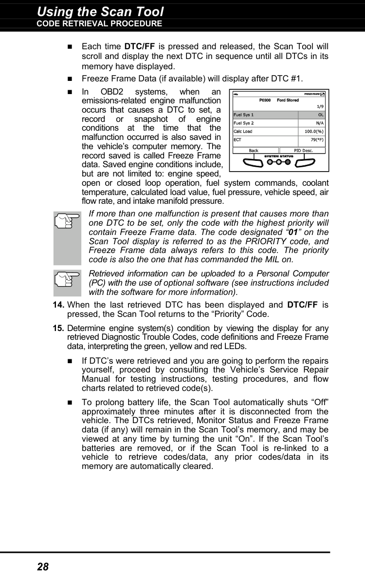
Each time DTC/FF is pressed and released, the Scan Tool will scroll and display the next DTC in sequence until all DTCs in its memory have displayed. Freeze Frame Data (if available) will display after DTC #1. In
Obd2
systems, when an emissions-related engine malfunction occurs that causes a DTC to set, a record or snapshot of engine conditions at the time that the malfunction occurred is also saved in the vehicle’s computer memory. The record saved is called Freeze Frame data. Saved engine conditions include, but are not limited to: engine speed, open or closed loop operation, fuel system commands, coolant temperature, calculated load value, fuel pressure, vehicle speed, air flow rate, and intake manifold pressure. If more than one malfunction is present that causes more than one DTC to be set, only the code with the highest priority will contain Freeze Frame data. The code designated “01” on the Scan Tool display is referred to as the PRIORITY code, and Freeze Frame data always refers to this code. The priority code is also the one that has commanded the MIL on. Retrieved information can be uploaded to a Personal Computer (PC) with the use of optional software (see instructions included with the software for more information).
Using the Scan Tool
THE SYSTEM MENU - VIEWING OEM ENHANCED DTCs
29
The System Menu
The System Menu provides the ability to retrieve “enhanced” DTCs, Anti- Lock Brake System (ABS), Supplemental Restraint System (SRS) DTCs and Tire Pressure Monitoring System (TPMS) DTCs for most BMW, Chrysler/Jeep, Ford/Mazda, GM/Isuzu, Honda/Acura, Hyundai, Mercedes Benz, Nissan, Toyota/Lexus, Volkswagen and Volvo vehicles. The types of enhanced data available depends on the vehicle make. You can also return to the Global OBD2 mode. Depending on the vehicle under test, some features and functions may not be available. To access the System Menu, pressSystem Menu
. Select the desired option, then press ENTER to view the selected information. To view ABS DTCs: Select ABS. Refer to VIEWING ABS DTCs on page 32 to view ABS DTCs for your vehicle. To view SRS DTCs: Select SRS. Refer to VIEWING SRS DTCs on page 33 to view SRS DTCs for your vehicle. To view TPMS DTCs: Select TPMS from the System Menu. Refer to VIEWING TPMS DTCs on page 34 to view TPMS DTCs for your vehicle. To view OEM enhanced DTCs: Select OEM Enhanced. Refer to VIEWING OEM ENHANCED DTCs on page 29 to view OEM enhanced DTCs for your vehicle. To perform a Network Test: Select Scan all Modules or Select Modules, as desired. Refer to NETWORK TEST on page 36 to view DTCs for other modules. VIEWING OEM ENHANCED DTCs (except Ford/Mazda) When (make) OEM Enhanced is chosen from the System Menu, the Scan Tool retrieves OEM enhanced DTCs from the vehicle’s computer.
Using the Scan Tool
VIEWING OEM ENHANCED DTCs (Ford/Mazda only)
30
Enter
to return to the Global OBD2 mode. VIEWING OEM ENHANCED DTCs (Ford/Mazda only) Mazda Enhanced DTCs are available for Mazda-branded Ford vehicles only. When Ford OEM Enhanced is chosen from the System Menu, the Ford OEM Enhanced menu displays. You may view DTCs for either the “Continuous Memory Test”, “KOEO (Key On Engine Off) Test” or “KOER (Key On Engine Running) Test.”Enter
. If KOER is selected, an advisory message shows.
Using the Scan Tool
VIEWING OEM ENHANCED DTCs (Ford/Mazda only)
31
Turn the ignition OFF, then back ON. Choose Continue. Proceed to step 3.

Using the Scan Tool
VIEWING ABS DTCs
32
In the case of long code definitions, a small arrow is shown in the upper/ lower right-hand corner of the code display area to indicate the presence of additional information. If no codes are present, a “System Pass” message displays. Choose System Menu to return to the System Menu.
Power/Link
again.Enter
to return to the Global OBD2 mode. VIEWING ABS DTCs Refer to the manufacturer’s website for vehicle makes covered.
Using the Scan Tool
VIEWING SRS DTCs
33
Enter
to return to the Global OBD2 mode. VIEWING SRS DTCs Refer to the manufacturer’s website for vehicle makes covered.
Using the Scan Tool
VIEWING TPMS DTCs
34
If the Scan Tool fails to link to the vehicle’s computer, a "Communication Error" message shows.
to return to the Global OBD2 mode. VIEWING TPMS DTCs Refer to the manufacturer’s website for vehicle makes covered.

Using the Scan Tool
VIEWING TPMS DTCs
35
Reading TPMS DTCs
Power/Link
again.
Using the Scan Tool
Network Test
36
Network Test
The Network Test lets you perform a scan of all vehicle modules, or of a single selected module, to retrieve DTCs associated with the module(s). To scan all modules:Enter
. A “One moment please” message displays while the Scan Tool scans all available modules. When the scan is complete, the Available Systems screen displays. The screen shows the number of DTCs recorded for each available module.Enter
. A “One moment please” message displays while the requested DTCs are retrieved. If the Scan Tool fails to link to the selected module, a “Communication Error” message shows.
Using the Scan Tool
Network Test
37
to return to the Global OBD2 mode. To scan a selected module:
Enter
. A “One moment please” message displays while the requested DTCs are retrieved.Enter
. A “One moment please” message displays while the requested DTCs are retrieved. If the Scan Tool fails to link to the selected module, a “Communication Error” message shows.
Using the Scan Tool
ERASING DIAGNOSTIC TROUBLE CODES (DTCs)
38
If the definition for the currently displayed code is not available, an advisory message shows. I/M MONITOR STATUS icons are not displayed when using the Network Test function. In the case of long code definitions, a small arrow is shown in the upper/lower right-hand corner of the code display area to indicate the presence of additional information. If no codes are present, the message "No (system name) DTC’s are presently stored in the vehicle’s computer" shows. Choose System Menu to return to the System Menu.
to return to the Global OBD2 mode. ERASING DIAGNOSTIC TROUBLE CODES (DTCs) When the Scan Tool’s ERASE function is used to erase DTCs from the vehicle's on-board computer, "Freeze Frame" data and manufacturer-specific-enhanced data are also erased. "Permanent" DTCs ARE NOT erased by the ERASE function. If you plan to take the vehicle to a Service Center for repair, DO NOT erase the codes from the vehicle's computer. If the codes are erased, valuable information that might help the technician troubleshoot the problem will also be erased. Erase DTCs from the computer's memory as follows: When DTCs are erased, the I/M Readiness Monitor Status program resets the status of all Monitors to a not run condition. To set all Monitors to a DONE status, an OBD2 Drive Cycle must be performed.

Using the Scan Tool
About Repairsolutions 2®
39
To erase enhanced, ABS, SRS, TPMS or Network DTCs: Press SYSTEM MENU to display the System Menu. Select the desired option, then press ENTER . Perform the appropriate Code Retrieval procedure and then proceed to step
. A
confirmation message shows. If you are sure you want to proceed, choose Erase DTCs to continue. If you do not want to proceed, choose Back to cancel the erase procedure.About Repairsolutions 2®
RepairSolutions 2® is a web-based service created to assist both Do-It- Yourself and Professional technicians in quickly and accurately diagnosing and repairing today’s vehicles. RepairSolutions 2 allows you to view and save the diagnostic data retrieved from a vehicle’s on-board computer(s) using your Code Reader. At the core of RepairSolutions 2 is an extensive knowledge database, developed by compiling and analyzing years worth of “real world” vehicle service data. RepairSolutions 2 builds on manufacturer-recommended diagnostic and repair information by providing verified, vehicle-specific fixes supplied by ASE technicians across the country. RepairSolutions 2 also provides access to an extensive knowledge database including: Verified Fixes – Find the most likely fixes reported and verified by ASE Technicians for the retrieved DTCs.
Using the Scan Tool
Connecting To Bluetooth / Wifi
40
Repair Instructions – View available repair instructions to properly perform the fix. Video Tutorials – Watch repair video tutorials for valuable repair tips. Technical Service Bulletins – Research known problems reported by vehicle manufacturers. Safety Recalls – Research known safety concerns applicable to a vehicle. And much more. Please visit www.innova.com for additional information. Hardware Requirements: Innova Scan Tool with Bluetooth/WiFi Android or iOS Smart Device Accessing RepairSolutions 2®
Connecting To Bluetooth / Wifi
Launch the RepairSolutions2 app an follow the prompts to establish Bluetooth and (optionally) WiFi connections, as follows:
Using the Scan Tool
Connecting To Bluetooth / Wifi
41
Skip.

Live Data Mode
Viewing Live Data
42
The Scan Tool lets you view and/or record "real-time" Live Data. This information includes values (volts, rpm, temperature, speed etc.) and system status information (open loop, closed loop, fuel system status, etc.) generated by the various vehicle sensors, switches and actuators. These are the same signal values generated by the sensors, actuators, switches and/or vehicle system status information used by the vehicle's computer when calculating and conducting system adjustments and corrections. The real time (Live Data) vehicle operating information (values/status) that the computer supplies to the Scan Tool for each sensor, actuator, switch, etc. is called Parameter Identification (PID) Data. Each PID (sensor, actuator switch, status, etc.) has a set of operating characteristics and features (parameters) that serve to identify it. The Scan Tool displays this information for each sensor, actuator, switch or status that is supported by the vehicle under test. WARNING: If the vehicle must be driven in order to perform a troubleshooting procedure, ALWAYS have a second person help you. One person should drive the vehicle while the other person observes the Scan Tool data. Trying to drive and operate the Scan Tool at the same time is dangerous, and could cause a serious traffic accident.
Viewing Live Data

Live Data Mode
CUSTOMIZING LIVE DATA (PIDs)
43
If communication with the vehicle is lost while viewing Live Data, an advisory message displays.
Enter.
If the Scan Tool fails to establish communication with the vehicle, a “Communication Error” message displays.
Live Data Mode
Recording (Capturing) Live Data
44
Recording (Capturing) Live Data
You can record and save several frames of Live Data information for each PID supported by the vehicle in the Scan Tool's memory. There are two ways that the Scan Tool can record Live Data: Record by DTC Trigger
Live Data Mode
Recording (Capturing) Live Data
45
Record by Manual Trigger If POWER/LINK is pressed at any time while in Live Data mode, any recorded Live Data will be erased from the Scan Tool’s memory. Record by DTC Trigger This function automatically records Live Data information when a DTC sets and saves it in the Scan Tool’s memory. The recorded data can be a valuable troubleshooting aid, particularly if you are experiencing a fault that is causing a DTC to set. The Scan Tool can record approximately 100 frames of Live Data.
Enter
. The checkmark is removed.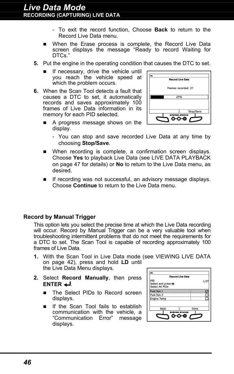
Live Data Mode
Recording (Capturing) Live Data
46Enter
. The Select PIDs to Record screen displays. If the Scan Tool fails to establish communication with the vehicle, a “Communication Error” message displays.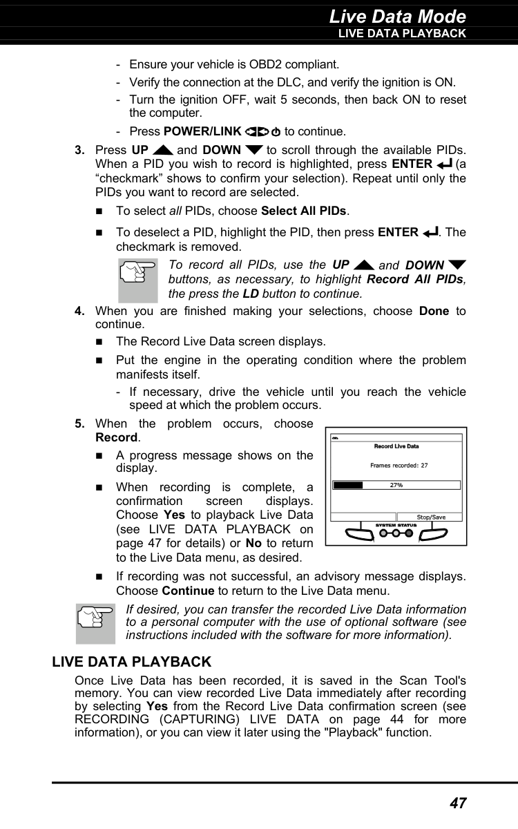
Live Data Mode
Live Data Playback
47
buttons, as necessary, to highlight Record All PIDs, the press the LD button to continue.
Live Data Playback
Once Live Data has been recorded, it is saved in the Scan Tool's memory. You can view recorded Live Data immediately after recording by selecting Yes from the Record Live Data confirmation screen (see RECORDING (CAPTURING) LIVE DATA on page 44 for more information), or you can view it later using the "Playback" function.
Live Data Mode
Live Data Playback
48
Down
, as necessary, to view all available PID data. When viewing recorded Live Data, look for any irregularities in any of the PID values/signal information (LTFT %, RPM, MAP, TEMP, etc.). If any PIDs are not within specification, or irregularities are detected, follow the procedures in the vehicle's service repair manual to perform additional troubleshooting and repair.
Additional Tests
The Main Menu
49
The Main Menu
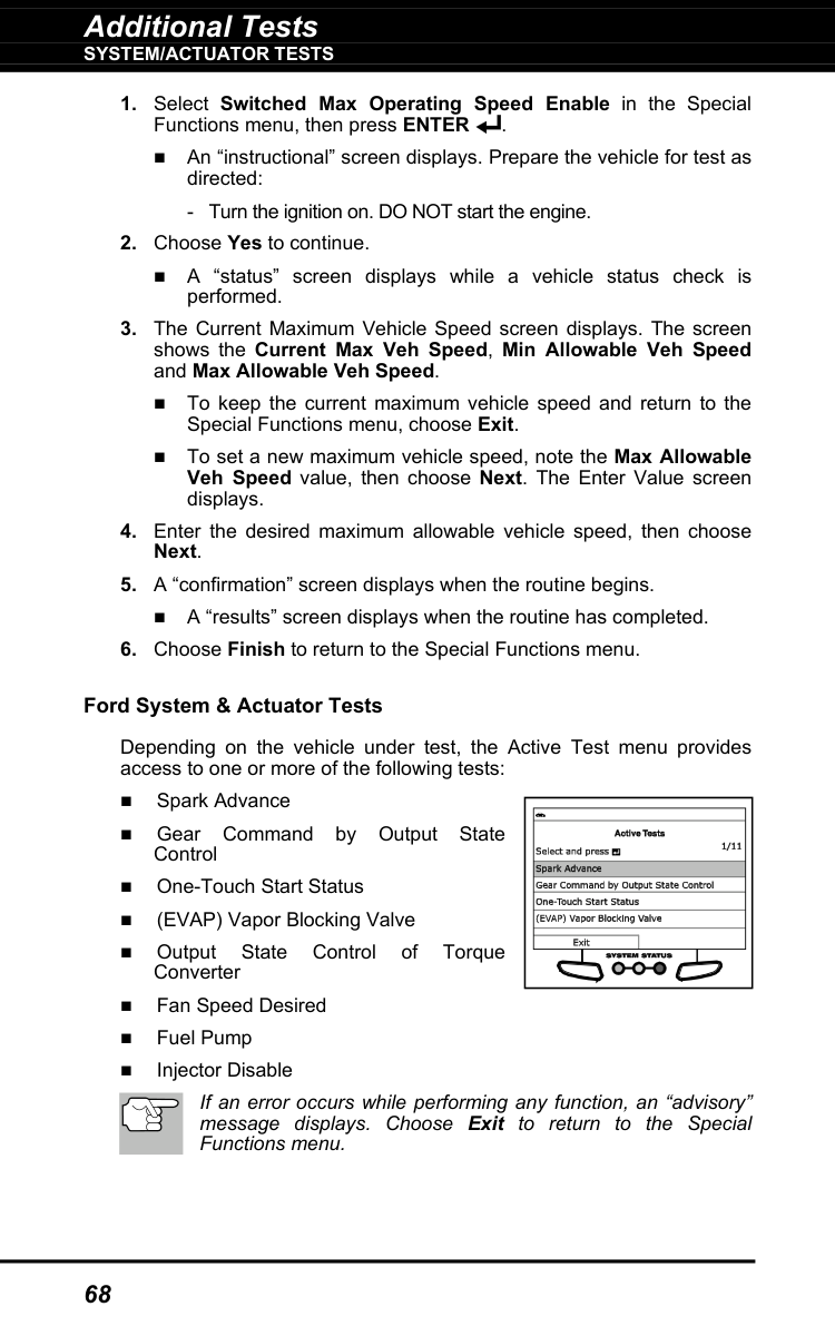
You can use the Scan Tool to perform additional diagnostic tests, view diagnostic and vehicle information stored in the vehicle's on-board computer, and configure the Scan Tool for your particular needs. These functions are accessed through the Main Menu. The following functions are available: System/Actuator Test – Displays a menu of system/actuator tests for the vehicle under test, which lets you perform active tests for various vehicle actuators and systems. Service Reset – Lets you reset the Oil Maintenance Light, reset the battery monitor system after battery replacement, perform calibration procedures for the vehicle’s Steering Angle Sensor (SAS), perform Electronic Parking Brake (EPB) cable replacement and reset, perform diesel particulate filter reset, or perform Anti-Lock Brake System (AVS) bleeding. Service Check – Lets you view the current engine oil level and oil life remaining. Hybrid Battery Check, Battery/Alternator Test – Performs a check of the vehicle’s battery and alternator system (or hybrid/EV battery system) to ensure the system is operating within acceptable limits. OBD Mode Test – Displays the System Tests menu, which lets you retrieve and view results for the O2 Sensor Test and OBD Monitor Test, and initiate a test of the vehicle’s EVAP system. Battery/Alternator Monitor – Performs a check of the vehicle’s battery and alternator system to ensure the system is operating within acceptable limits. Drive Cycle Procedure – Lets you view drive cycle procedures for a selected vehicle monitor. DLC Locator – Lets you find the location of the Data Link Connector (DLC) for a specified vehicle. Vehicle Information – Displays the Vehicle Info menu, which lets you retrieve and view reference information for the vehicle under test. Firmware Version – Displays the Scan Tool’s firmware version. Tool Library – Displays the Tool Library menu, which provides access to OBD1 and OBD2 DTC libraries and to definitions for Monitor icons and LED indicators. Tool Settings – Displays the Tool Settings menu, which lets you make adjustments and settings to configure the Scan Tool to your particular needs. The OBD Mode Test and Vehicle Information options are shown only when the Scan Tool is in Global OBD2 mode.
Additional Tests
System/Actuator Tests
50
System/Actuator Tests
System/Actuator Tests let you perform active tests for various vehicle actuators and systems. The specific tests available depend on the vehicle make and model. Chrysler System & Actuator Tests Depending on the vehicle under test, the Special Functions menu provides access to one or more of the following tests: Set Throttle Blade Position Throttle Learn Mode EGR Mass Flow Rate Test Routine Start Cam Crank Relearn Idle Up Feature Enable IMA Rapid Calibration Learn ETC Manual DPF Regeneration Compression Test Cylinder Performance Test EGR System Test ESIM Forced Monitor Test ETC System Test ETC Throttle Follower Test Pedal Follower Mode NVLD Forced Monitor Test Routine Start Purge Vapor System Test Set Engine RPM Set RPM Test Set Engine RPM System Test Leak Detection Pump (LDP) Test LDP Forced Monitor Test Injector Kill System Test VVT System Test Pedal Follower Mode Reverse Brake Torque Test PTO & Idle Up Minimum Airflow Test Routine Start EGR Desired Delta Position Switched Max Operating Speed Enable.
Additional Tests
System/Actuator Tests
51
If an error occurs while performing any function, an “advisory” message displays. Choose Exit to return to the Special Functions menu. Set Throttle Blade Position

Additional Tests
System/Actuator Tests
52

Additional Tests
System/Actuator Tests
53
Enter
.
Additional Tests
System/Actuator Tests
54
An “instructional” screen displays. Prepare the vehicle for test as directed:

Additional Tests
System/Actuator Tests
55
An “instructional” screen displays. Prepare the vehicle for test as directed:
Additional Tests
System/Actuator Tests
56
An “instructional” screen displays. Prepare the vehicle for test as directed:
Enter
. An “instructional” screen displays. Prepare the vehicle for test as directed: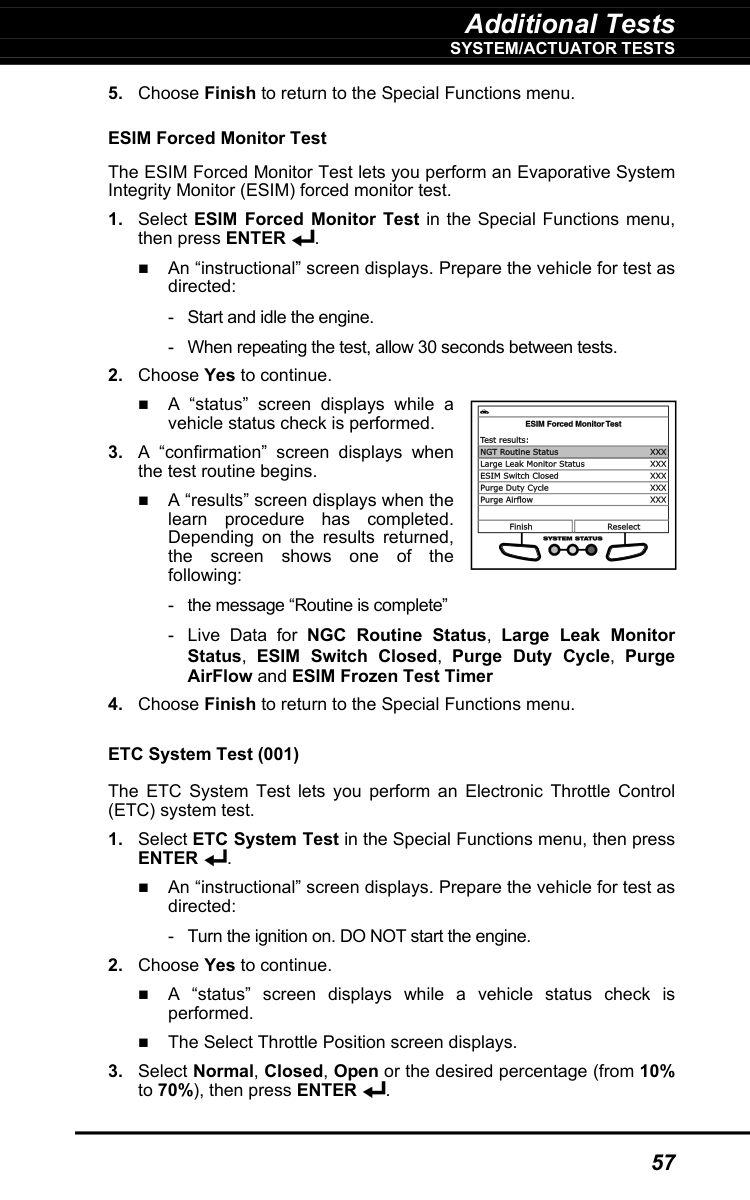
Additional Tests
System/Actuator Tests
57
Enter
. An “instructional” screen displays. Prepare the vehicle for test as directed: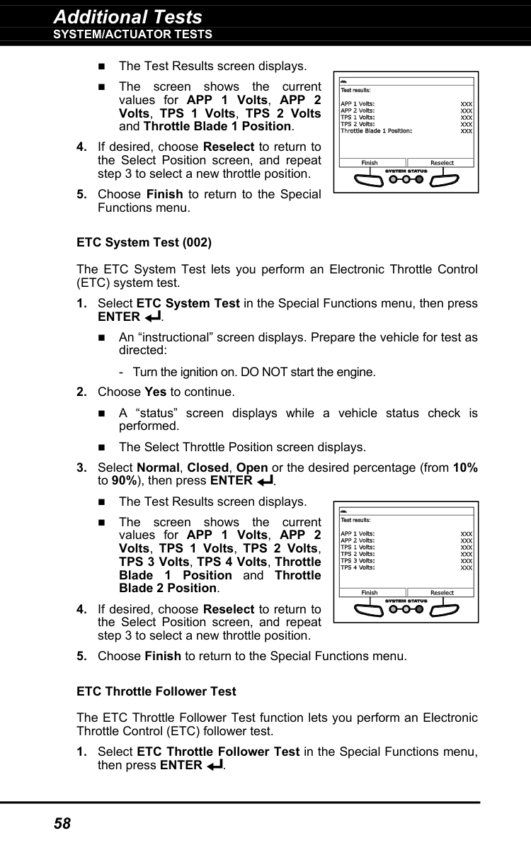
Additional Tests
System/Actuator Tests
58
The Test Results screen displays. The screen shows the current values for APP 1 Volts, APP 2 Volts, TPS 1 Volts, TPS 2 Volts and Throttle Blade 1 Position.
Enter
. An “instructional” screen displays. Prepare the vehicle for test as directed:
Additional Tests
System/Actuator Tests
59
An “instructional” screen displays. Prepare the vehicle for test as directed:
Additional Tests
System/Actuator Tests
60
An “instructional” screen displays. Prepare the vehicle for test as directed:
Additional Tests
System/Actuator Tests
61
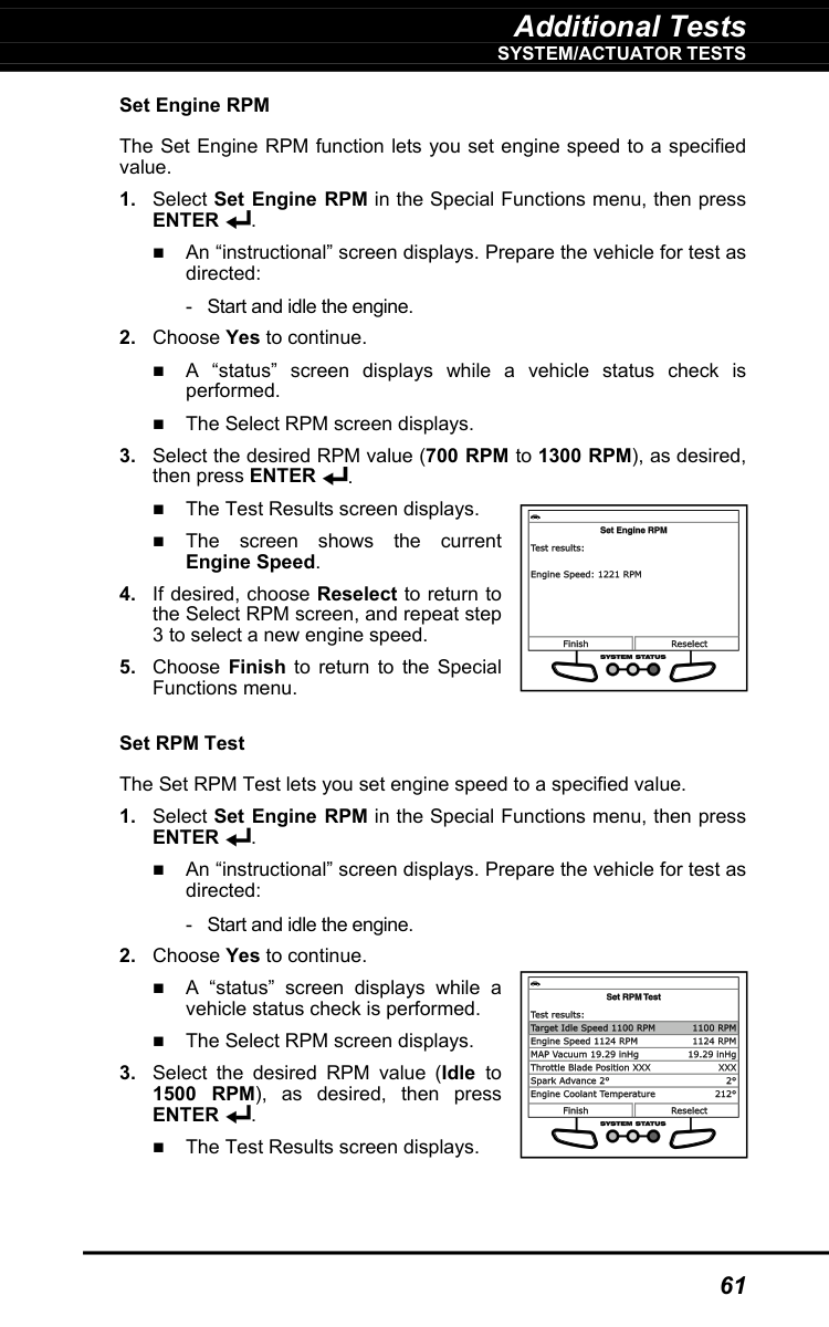
Set Engine RPM The Set Engine RPM function lets you set engine speed to a specified value.
Enter
. An “instructional” screen displays. Prepare the vehicle for test as directed:Enter
. An “instructional” screen displays. Prepare the vehicle for test as directed:Enter
. The Test Results screen displays.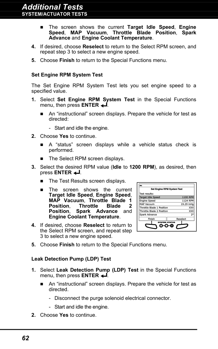
Additional Tests
System/Actuator Tests
62
The screen shows the current Target Idle Speed, Engine Speed, MAP Vacuum, Throttle Blade Position, Spark Advance and Engine Coolant Temperature.
Additional Tests
System/Actuator Tests
63
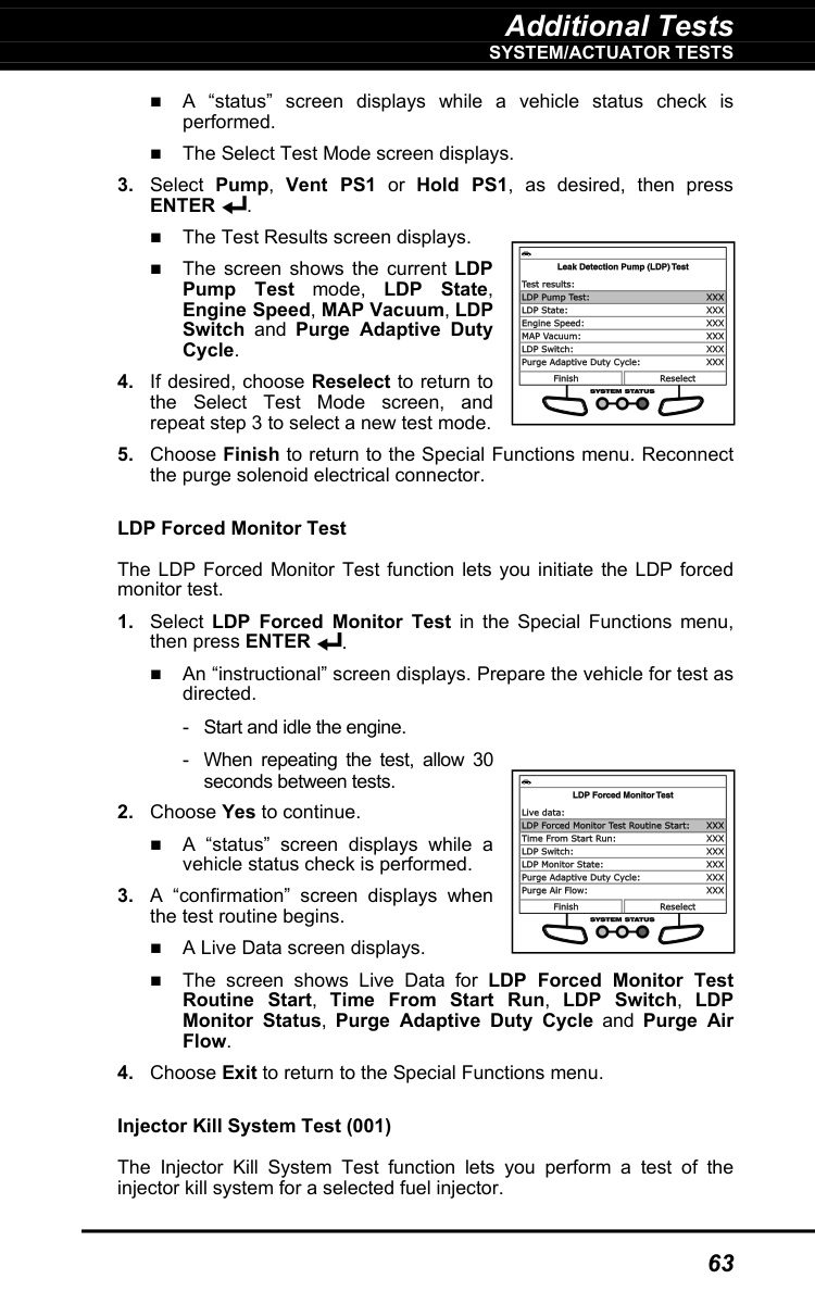
A “status” screen displays while a vehicle status check is performed. The Select Test Mode screen displays.
Enter
. The Test Results screen displays. The screen shows the current LDP Pump Test mode, LDP State, Engine Speed, MAP Vacuum, LDP Switch and Purge Adaptive Duty Cycle.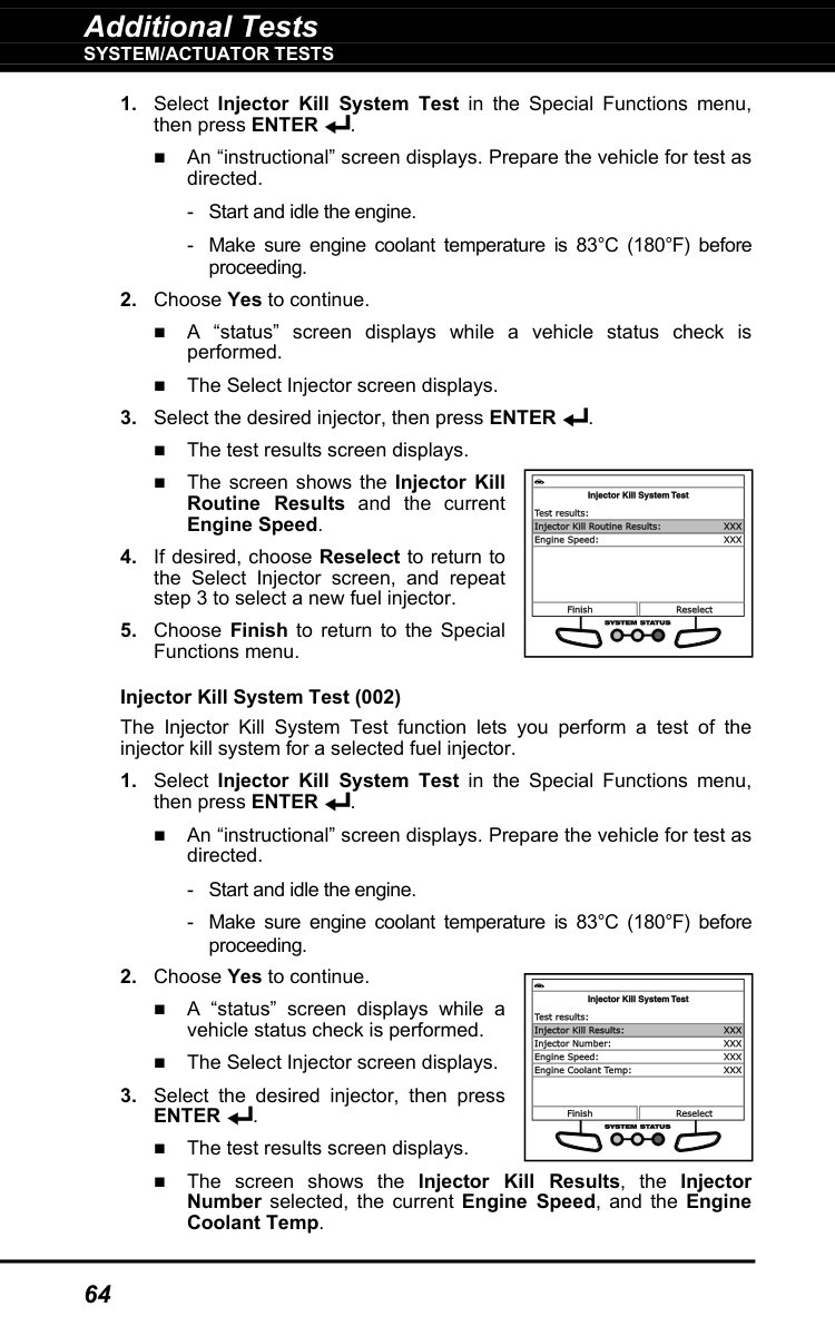
Additional Tests
System/Actuator Tests
64
Enter
. The test results screen displays. The screen shows the Injector Kill Results, the Injector Number selected, the current Engine Speed, and the Engine Coolant Temp.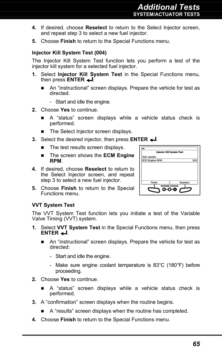
Additional Tests
System/Actuator Tests
65
Rpm.
Enter
. An “instructional” screen displays. Prepare the vehicle for test as directed:
Additional Tests
System/Actuator Tests
66
Reverse Brake Torque Test
Enter
. An “instructional” screen displays. Prepare the vehicle for test as directed:
Additional Tests
System/Actuator Tests
67
Additional Tests
System/Actuator Tests
68
Additional Tests
System/Actuator Tests
69
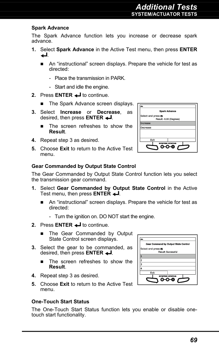
Spark Advance The Spark Advance function lets you increase or decrease spark advance.
Additional Tests
System/Actuator Tests
70
Enter
. An “instructional” screen displays. Prepare the vehicle for test as directed:Enter
. The screen refreshes to show the Result.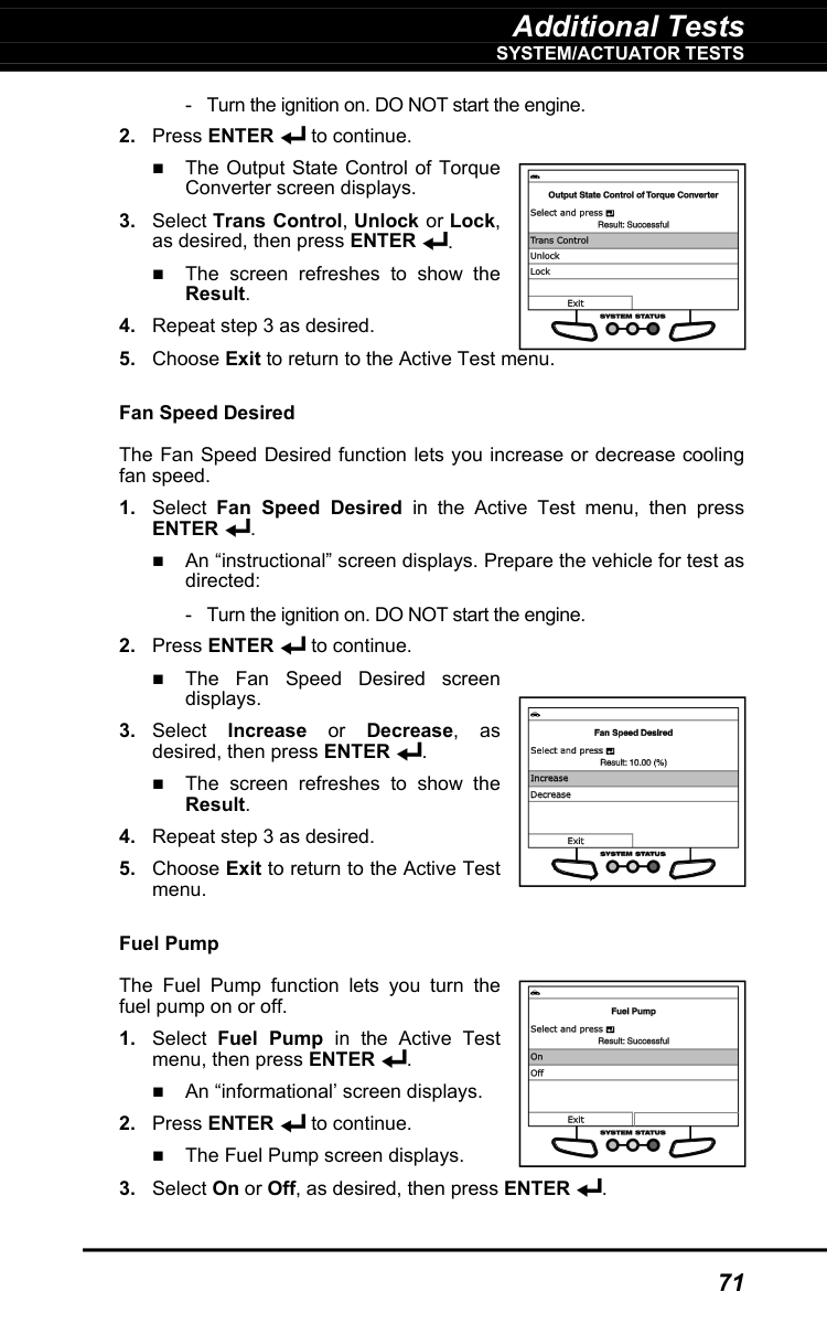
Additional Tests
System/Actuator Tests
71
Enter
. An “instructional” screen displays. Prepare the vehicle for test as directed: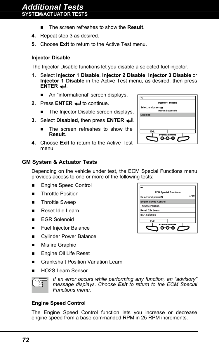
Additional Tests
System/Actuator Tests
72
The screen refreshes to show the Result.
Enter
. An “informational’ screen displays.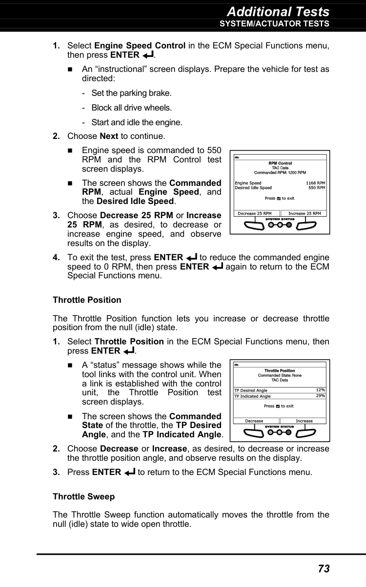
Additional Tests
System/Actuator Tests
73
Additional Tests
System/Actuator Tests
74
Tac
Motor Command, TP Sensor 1, TP Sensor 2, TAC Motor and TP Sensors 1 and 2.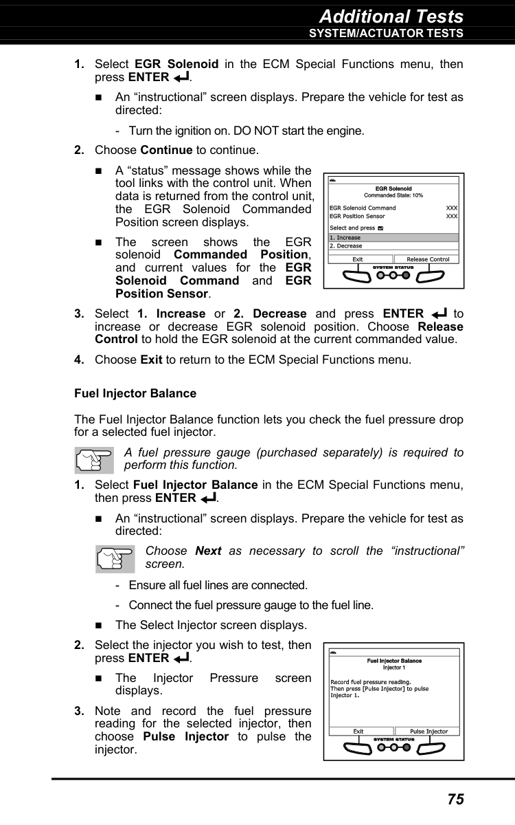
Additional Tests
System/Actuator Tests
75
Egr
solenoid Commanded Position, and current values for the EGR Solenoid Command and EGR Position Sensor.
Additional Tests
System/Actuator Tests
76
The Injector Pressure Drop screen displays.

Additional Tests
System/Actuator Tests
77
buttons to specify the desired percentage of remaining engine oil life.

Additional Tests
System/Actuator Tests
78
App
Indicated Angle.
Additional Tests
System/Actuator Tests
79
A “status” screen displays the Commanded State as Reset while the reset is in progress.

Additional Tests
System/Actuator Tests
80
An “instructional” screen displays. Perform the following:
Egr
control, an “advisory” message displays. Choose Back to return to the Active Test menu.
Additional Tests
System/Actuator Tests
81
Lift
SENSOR voltage, and may showEngine Speed.

Additional Tests
System/Actuator Tests
82

Additional Tests
System/Actuator Tests
83
Iac
Command.
A “confirmation” screen displays when testing is complete.
Additional Tests
System/Actuator Tests
84
To perform the SINGLE SOLENOID test:
Enter
. An “instructional” screen displays. Prepare the vehicle for test as directed:Enter
. An “instructional” screen displays. Prepare the vehicle for test as directed:
Additional Tests
System/Actuator Tests
85
Enter
. An “instructional” screen displays. Prepare the vehicle for test as directed: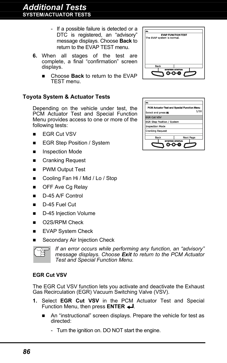
Additional Tests
System/Actuator Tests
86
Additional Tests
System/Actuator Tests
87

Additional Tests
System/Actuator Tests
88

Additional Tests
System/Actuator Tests
89
An “instructional” screen displays. Prepare the vehicle for test as directed:

Additional Tests
System/Actuator Tests
90

Additional Tests
System/Actuator Tests
91

Additional Tests
System/Actuator Tests
92
Evap Vsv Check

Additional Tests
System/Actuator Tests
93
Lev Ii Sys Check

Additional Tests
System/Actuator Tests
94
Evap
Vsv
Check
Key-Off
MONITOR SYSTEM – Closed TankVsv,
Vent Valve, Vacuum Pump and Fuel VCV.
Additional Tests
System/Actuator Tests
95
An “instructional” screen displays. Prepare the vehicle for test as directed:
Additional Tests
Performing Service Resets
96
Enter
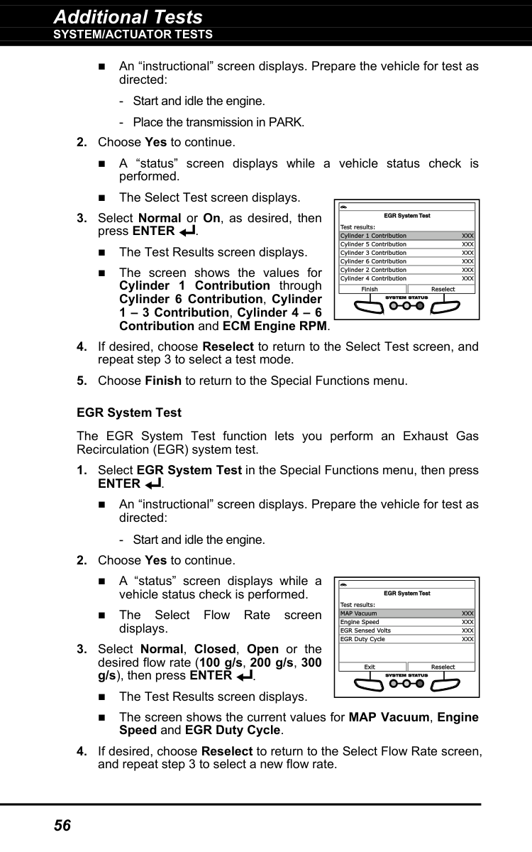
. The Test Results screen displays. When the test has completed, an “advisory” message displays. Choose Continue to return to the Select Test screen, or, choose Exit to return to the PCM Actuator Test and Special Function Menu.Performing Service Resets
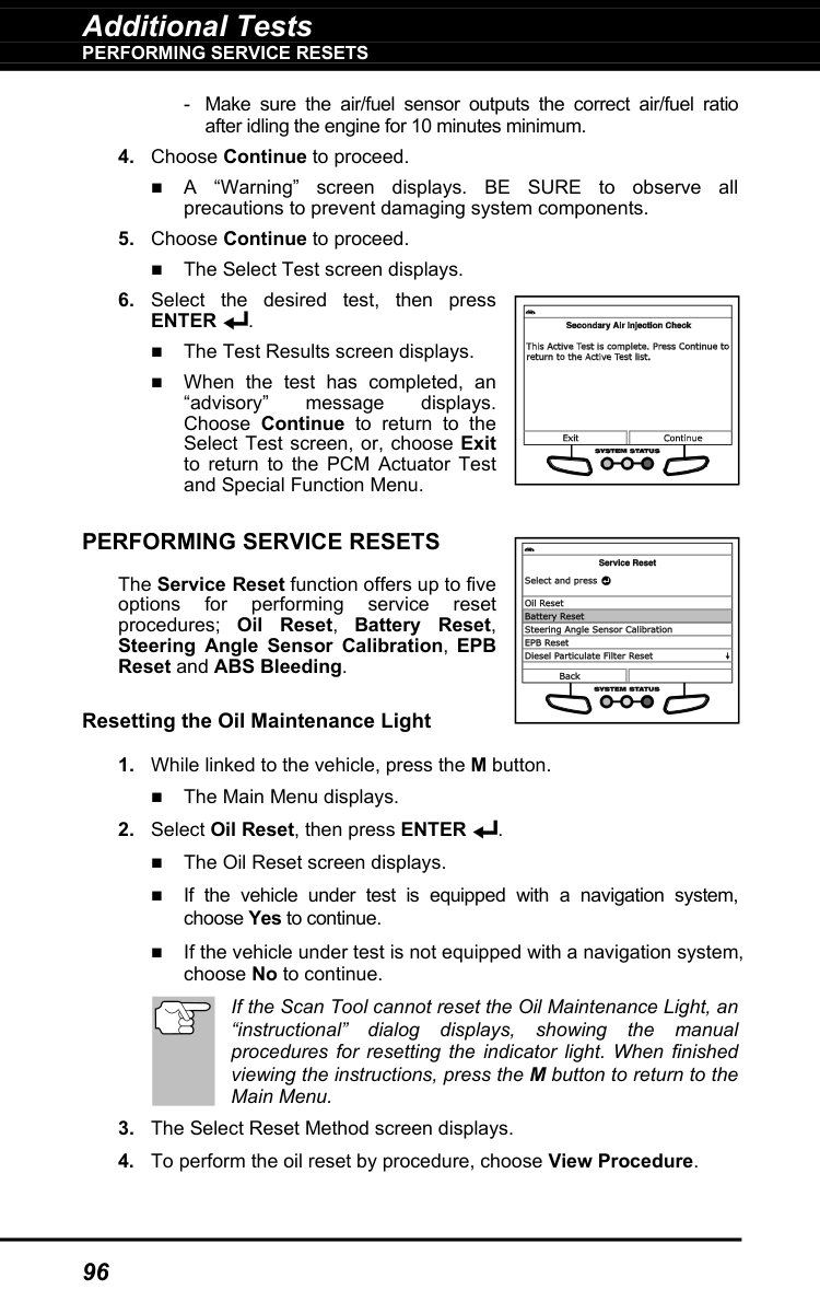
The Service Reset function offers up to five options for performing service reset procedures; Oil Reset, Battery Reset, Steering Angle Sensor Calibration, EPB Reset and ABS Bleeding. Resetting the Oil Maintenance Light
Additional Tests
Performing Service Resets
97
An “instructional” dialog displays, showing the manual procedures for resetting the indicator light. When finished viewing the instructions, press the M button to return to the Main Menu.
Additional Tests
Performing Service Resets
98
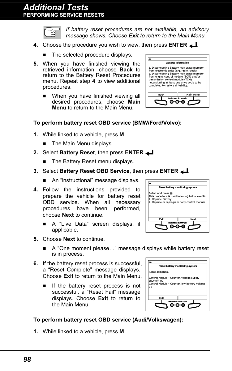
If battery reset procedures are not available, an advisory message shows. Choose Exit to return to the Main Menu.
Additional Tests
Performing Service Resets
99
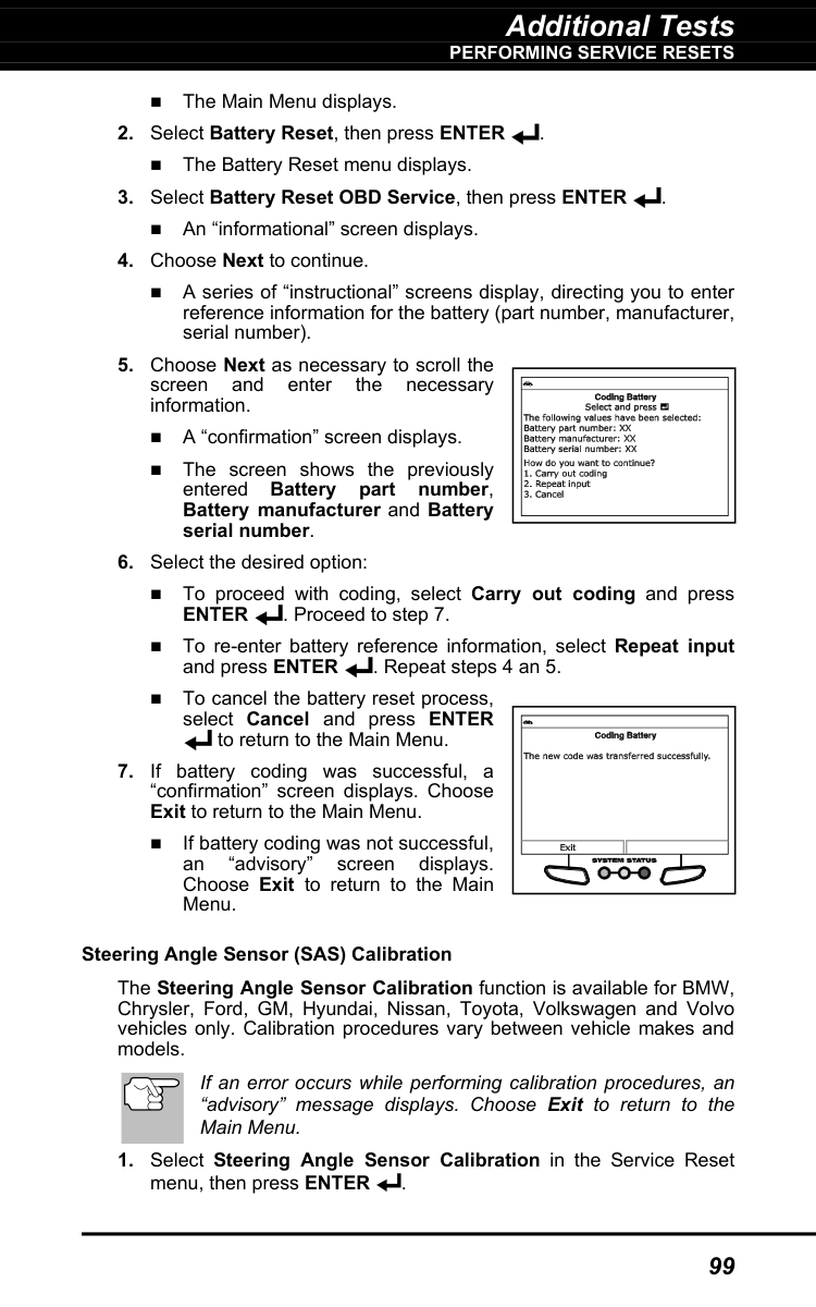
The Main Menu displays.
Enter
. Proceed to step 7. To re-enter battery reference information, select Repeat input and press ENTER . Repeat steps 4 an 5. To cancel the battery reset process, select Cancel and press ENTER to return to the Main Menu.
Additional Tests
Performing Service Resets
100
For some vehicles, a submenu displays. Select the desired option, then press ENTER . Proceed to step 2. If SAS calibration is not supported by the vehicle under test, an “advisory” message displays. Choose Exit to return to the Main Menu.
Enter
. Proceed to step 2. If EPB reset is not supported by the vehicle under test, an “advisory” message displays. Choose Exit to return to the Main Menu.
Additional Tests
Performing Service Resets
101

Additional Tests
Performing Service Resets
102
Diesel Particulate Filter Reset (General Motors)

Additional Tests
Performing Service Resets
103
If the selected function is not supported by the vehicle under test, an “advisory” message may display. Choose End to return to the Diesel Particulate Filter Reset menu.
Enter
. A “One moment” message may display. A submenu displays. Select the desired option, then pressEnter
. Proceed to step 2.
Additional Tests
Service Check - Hybrid Battery Check, Battery Alternator Test
104
Performing A Service Check
The Service Check function lets you check brake pad status, current oil level and oil life, and transmission fluid temperature.Enter
. The Service Check screen displays. The screen shows the current Brake Pads status, Engine Oil Level, Oil Life Remaining and Transmission Fluid Temperature.Hybrid Battery Check, Battery Alternator Test
The Scan Tool can perform a check of the vehicle’s battery and alternator system (or hybrid/EV battery system) to ensure the system is operating within acceptable limits.Enter
. If the vehicle is an electric or hybrid vehicle, the Hybrid Battery Monitor screen shows a graphic display of the current state of charge for all cells in the battery pack displays. If the Hybrid Battery Monitor is not supported by the vehicle under test, an “advisory” message displays. Choose Back to return to the Main Menu. If the vehicle is not an electric or hybrid vehicle, the Battery/Alternator Monitor menu displays (see BATTERY/ALTERNATOR MONITOR on page 108 for details).
Additional Tests
System Test Menu
105
System Test Menu
Additional tests are accessed through the System Tests menu. The following functions are available: O2 Sensor Test - Retrieves and displays O2 sensor monitor test results from your vehicle's on-board computer. OBD Monitor Test - Retrieves and displays test results for emission-related powertrain components and systems that are not continuously monitored. EVAP Test - Performs a leak test for the vehicle's EVAP system.Enter
. The System Test menu displays. If OBD Mode Tests is not shown on the Main Menu, the System Tests functions are not available for the vehicle under test. O2 Sensor Test OBD2 regulations require that applicable vehicles monitor and test operation of the oxygen (O2) sensors to identify problems that can affect fuel efficiency and vehicle emissions. These tests are performed automatically when engine operating conditions are within predefined limits. Results of these tests are stored in the on-board computer's memory. The O2 Sensor Test function lets you retrieve and view O2 sensor monitor test results for the most recently completed tests from the vehicle's on-board computer. The Scan Tool does not perform O2 sensor tests, but retrieves results from the most recently performed O2 sensor tests from the on-board computer's memory. You may retrieve O2 sensor test results for only one test of one sensor at any given time.Enter
.
Additional Tests
System Test Menu
106
If O2 sensor tests are not supported by the vehicle under test, an advisory message displays. Choose Back (to return to the System Tests menu) or Main Menu, as desired.
Enter
to display the test results. The display shows the following information: Test ID number Module ID number
Additional Tests
System Test Menu
107
Component ID number Min or Max test limit (Only one test limit, either Min or Max, is shown for any given test) Test Value and status Status is calculated by the Scan Tool by comparing the Test Value against the displayed test limit (either Min or Max). Status is shown as either Low, High or OK.

Additional Tests
Battery/Alternator Monitor
108
Enter
.Battery/Alternator Monitor
The Scan Tool can perform a check of the vehicle’s battery and alternator system to ensure the system is operating within acceptable limits. You can perform a battery check only, or an alternator system (battery and alternator) check. To perform a battery check ONLY: When Hybrid Battery Check, Battery/Alternator Test is selected from the Main Menu and the vehicle is not an electric or hybrid vehicle, the Battery/Alternator Monitor menu displays. Proceed to step 3.Enter
.
Additional Tests
Battery/Alternator Monitor
109
An “instructional” message displays, showing the procedures to prepare the vehicle for the battery check.

Additional Tests
Battery/Alternator Monitor
110
Green = Good Yellow = Normal Red = Warning/Bad
Enter
. An “instructional” message shows.
Additional Tests
Viewing Drive Cycle Procedures
111
Red = Excessive over charging or under charging If the alternator voltage is less than 9 V, the red, yellow and green SYSTEM STATUS LEDs will flash on and off.
Viewing Drive Cycle Procedures
A Drive Cycle for a Monitor requires that the vehicle is driven in such a way that all the required “Enabling Criteria” for the Monitor to run and complete its diagnostic testing are met. You can use the Scan Tool to view the Drive Cycle procedures for a selected Monitor.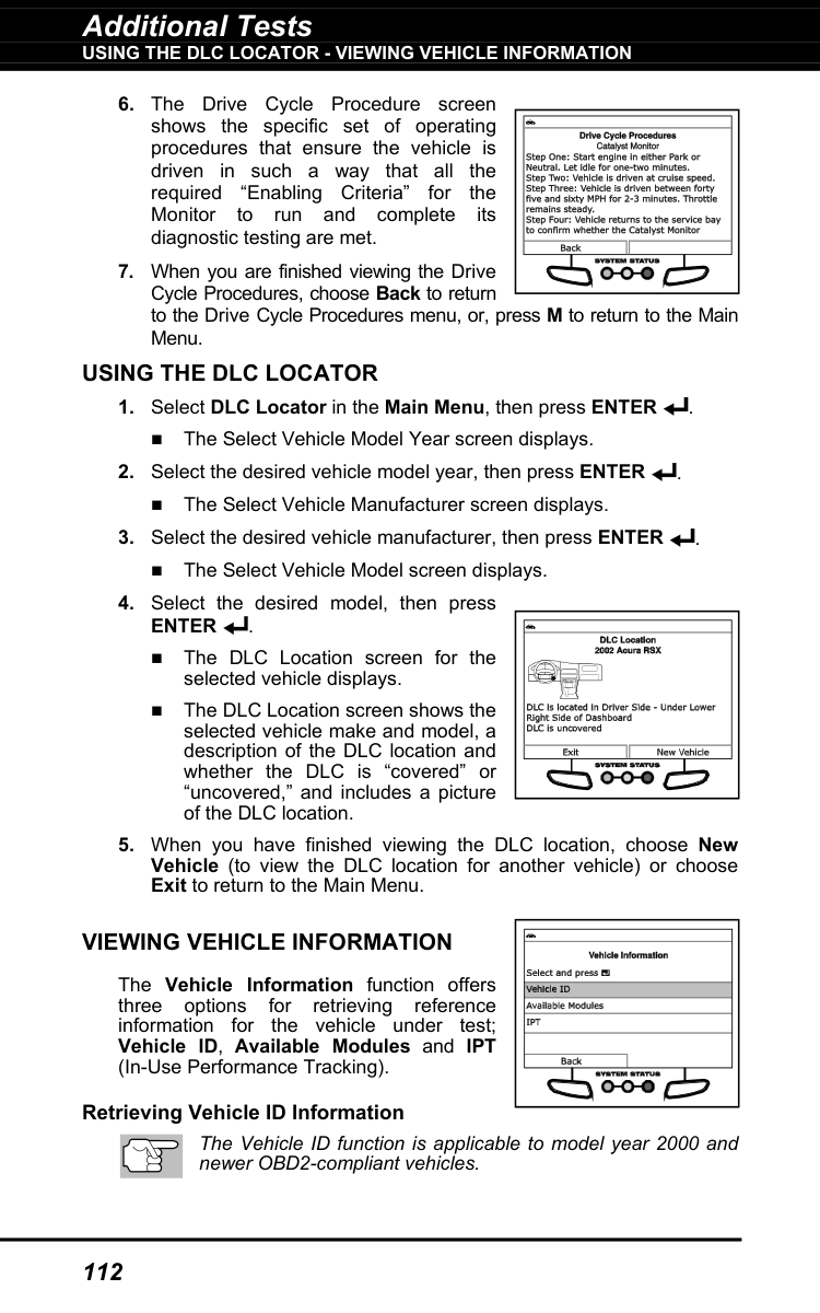
Additional Tests
Using The Dlc Locator - Viewing Vehicle Information
112
Using The Dlc Locator
Enter
. The DLC Location screen for the selected vehicle displays. The DLC Location screen shows the selected vehicle make and model, a description of the DLC location and whether the DLC is “covered” or “uncovered,” and includes a picture of the DLC location.Viewing Vehicle Information
The Vehicle Information function offers three options for retrieving reference information for the vehicle under test; Vehicle ID, Available Modules and IPT (In-Use Performance Tracking). Retrieving Vehicle ID Information The Vehicle ID function is applicable to model year 2000 and newer OBD2-compliant vehicles.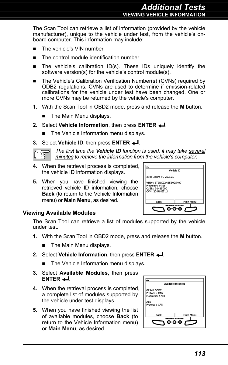
Additional Tests
Viewing Vehicle Information
113
The Scan Tool can retrieve a list of information (provided by the vehicle manufacturer), unique to the vehicle under test, from the vehicle's on- board computer. This information may include: The vehicle's VIN number The control module identification number The vehicle's calibration ID(s). These IDs uniquely identify the software version(s) for the vehicle's control module(s). The Vehicle's Calibration Verification Number(s) (CVNs) required by ODB2 regulations. CVNs are used to determine if emission-related calibrations for the vehicle under test have been changed. One or more CVNs may be returned by the vehicle's computer.
Enter
.
Additional Tests
Viewing The Firmware Version - The Tool Library
114
Viewing In-use Performance Tracking (IPT) The Scan Tool can retrieve In-use Performance Tracking (IPT) statistics for monitors supported by the vehicle under test. Two values are returned for each monitor; the number of times that all conditions necessary for a specific monitor to detect a malfunction have been encountered (XXXCOND), and the number of times that the vehicle has been operated under the specific conditions for the monitor (XXXCOMP). Statistics are also provided for the number of times the vehicle has been operated in OBD monitoring conditions (OBDCOND), and the number of times the vehicle’s engine has been started (IGNCNTR).
Viewing The Firmware Version
The Tool Library
The Tool Library contains valuable reference information for the Scan Tool. The following functions are available:
Additional Tests
The Tool Library
115
Icon Meaning – Shows the full names for the I/M MONITOR STATUS icons shown and descriptions of informational icons on the Scan Tool’s display. DTC Library – Provides access to libraries of OBD1 and OBD2 DTC definitions. Hotkey Legend - Shows functional descriptions for the Scan Tool’s hotkeys. LED Meaning – Provides descriptions of the meaning of the Scan Tool SYSTEM STATUS LEDs.
Enter
. The screen shows a list of Monitor for the selected category. Choose Back to return to the Icon Meaning menu. If desired, repeat step 2 to view additional Icon Meanings.Obd1
Library, then pressEnter
.
Additional Tests
The Tool Library
116
The Select Manufacturer screen displays.
Enter
to view the DTC definition.Enter
. The Select Library screen displays.Obd2
Library, then pressEnter
. The Select Manufacturer screen displays.
Additional Tests
The Tool Library
117
Dtc
type (P=Powertrain, U=Network, B=Body, C=Chassis), then choose Next Digit. The selected character displays solid, and the next character is highlighted.Enter
to view the DTC definition.Enter
. The LED Definitions screen displays.
Additional Tests
Tool Settings
118
Tool Settings
The Scan Tool lets you make several adjustments and settings to configure the tool to your particular needs. The following functions can be performed: Adjust Brightness: Adjusts the brightness of the display screen. Audible Tone: Turns the Scan Tool’s audible tone “on” and “off.” When turned “on,” a tone sounds each time a button is pressed. Live Data Description: Enables “expanded” definition functionality for the Live Data mode. Language Selection: Sets the display language for the Scan Tool to English, French or Spanish. Unit of Measurement: Sets the Unit of Measurement for the Scan Tool’s display to USA or metric. To enter the Tool Settings mode:Enter
. The Tool Setting menu displays.
Additional Tests
Tool Settings
119
To return to the Tool Settings menu without making changes, choose Back. Enabling/Disabling Live data Descriptions

Using Scan Tool Memory
Viewing Data In Memory
120
When you retrieve DTCs from a vehicle, the data is saved to the Scan Tool’s memory. The Scan Tool stores data for the three most recent vehicle’s tested. Each time you retrieve DTCs from a new vehicle, existing data for the oldest vehicle in the Scan Tool's memory is overwritten with the new data.
Viewing Data In Memory
When you turn the Scan Tool on while NOT connected to a vehicle, and data is currently saved in the Scan Tool’s memory, the Scan Tool enters Memory mode. You can view DTCs and Live Data stored in the Scan Tool’s memory.Power/Link
to turn the Scan Tool on. If the Scan Tool’s batteries are low, a warning message displays. Replace the batteries before con- tinuing.Dtc.
If there are no DTCs currently stored in the Scan Tool’s memory, an advisory message shows on the display. Press DTC/FF to scroll through all stored DTCs, and to view Freeze Frame data for the priority DTC. When all DTCs have been displayed and DTC/FF is pressed, the Scan Tool displays the first enhanced DTC stored in memory. Press DTC/FF to scroll through all stored enhanced DTCs. Choose FixAssist to view FixAssist information for the “priority”Dtc.
Choose Freeze Frame to view Freeze Frame data for the “priority” DTC.
Warranty and Servicing
121