
Innova 3100 OBD2 Code Reader
Ask AI
— answers from the official manualAnswers from the official manual.
Common questions
Common Questions
36 totalWhat vehicles are compatible with the Innova 3100 OBD2 Code Reader?
The Innova 3100 is designed to work on all OBD2 compliant vehicles, which includes all 1996 and newer cars and light trucks sold in the United States. This covers all domestic, Asian, and European vehicles. Some 1994 and 1995 vehicles may also be compatible if their Vehicle Emissions Control Information (VECI) label states 'OBD II Certified.' The tool is also compatible with all OBD2 protocols, including CAN (Controller Area Network). (Page 6)
How do I connect the Code Reader to my vehicle and retrieve diagnostic trouble codes?
Turn the ignition off, locate the 16-pin Data Link Connector (DLC) under the dashboard, and connect the Code Reader cable — the connector is keyed and only fits one way. Once connected, turn the ignition ON (do not start the engine), and the Code Reader will automatically turn on, display 'rEAd,' and retrieve any stored codes within 10–60 seconds. If more than one code is present, press the SCROLL button to view additional codes. (Page 17)
What does the red LED indicator mean on the Code Reader?
A red LED indicates there is a problem with one or more of the vehicle's systems, and that Diagnostic Trouble Codes (DTCs) are present in the vehicle's computer memory. In this condition, the Malfunction Indicator Lamp (Check Engine light) on the vehicle's dashboard will be lit steady. A vehicle displaying a red LED is not ready for an Emissions Test (Smog Check) and should be inspected or repaired before driving further. (Page 19)
How do I erase Diagnostic Trouble Codes (DTCs) from my vehicle's computer?
After completing the code retrieval procedure, press and release the ERASE button — the display will show 'SurE' to confirm. Press ERASE again to proceed, and the display will show 'donE' before automatically re-linking to confirm codes have been cleared. Note that erasing DTCs also clears Freeze Frame data and resets all Monitor statuses to 'not run,' requiring an OBD2 Drive Cycle to restore them. If you plan to take the vehicle to a service center, do not erase codes beforehand. (Page 20–21)
Is it safe to connect or disconnect the Code Reader while the ignition is on?
No — connecting or disconnecting the Code Reader when the ignition is ON can damage both the test equipment and the vehicle's electronic components. Always turn the ignition OFF before connecting or disconnecting the Code Reader from the vehicle's Data Link Connector (DLC). (Page 6)
What does 'Freeze Frame' data mean and when is it stored?
Freeze Frame data is a snapshot of engine and emissions system conditions recorded at the moment a Diagnostic Trouble Code caused the Malfunction Indicator Lamp (MIL) to turn on. It includes information such as fuel system status, engine load, coolant temperature, fuel trim value, MAP vacuum, engine RPM, and DTC priority. This data is always associated with the highest priority code (Code #1) and is also erased when the ERASE function is used. (Page 37)
Show 30 more questions
How can I tell if my vehicle is ready for an emissions test (smog check)?
What do the green, yellow, and red LEDs mean on the Code Reader?
How do I erase diagnostic trouble codes from my vehicle's computer?
What safety precautions should I follow when using the Code Reader?
How do I replace the batteries in the Innova 3100 Code Reader?
What should I check on my vehicle before using the Code Reader to diagnose problems?
Is my vehicle ready for an emissions test (smog check)?
What is a 'pending' diagnostic trouble code and what does it mean?
How do I erase diagnostic trouble codes (DTCs) from the Innova 3100?
How often should I replace the batteries in the Innova 3100?
What vehicles can the Innova 3100 OBD2 Code Reader work with?
Where is the Data Link Connector (DLC) located on my vehicle?
What do the three LED lights on the Code Reader indicate?
What steps should I follow to retrieve diagnostic trouble codes from my vehicle?
What does it mean when the Code Reader displays a 'Pending' code?
Can I erase diagnostic trouble codes from my vehicle's computer?
What is the difference between a Type A and Type B Diagnostic Trouble Code?
How do I connect the Innova 3100 Code Reader to my vehicle?
What does a blinking LED on the Innova 3100 indicate?
How do I retrieve diagnostic trouble codes (DTCs) using the Innova 3100?
What should I do if my vehicle has pending DTCs?
How long should the engine be run for OBD II drive cycle completion?
What does the red LED indicate on the Innova 3100?
What is a full OBD II drive cycle?
How do I determine if my vehicle is ready for an emissions test?
What does the yellow LED indicator mean on the Code Reader?
How do I replace the batteries in the Code Reader?
What should I check on my vehicle before using the Code Reader?
How do I retrieve diagnostic trouble codes (DTCs) from my vehicle?
What is I/M Readiness and why is it important?
Full Manual
102 pages
OWNER’S MANUAL The Easiest And Best Way To Troubleshoot 1996 and Newer OBD II Vehicles!
| | | |---|---|
| | | |---|---|
Table of Contents
Title Page No. INTRODUCTION
Congratulations! . . . . . . . . . . . . . . . . . . . . . . . . . . . . . . . . . . . . . 1 What is OBD? . . . . . . . . . . . . . . . . . . . . . . . . . . . . . . . . . . . . . . . 2
############### YOU CAN DO IT! . . . . . . . . . . . . . . . . . . . . . . . . . . . . . . . . . . . . . . . . . 3 SAFETY PRECAUTIONS
Safety First! . . . . . . . . . . . . . . . . . . . . . . . . . . . . . . . . . . . . . . . . 4 ABOUT THE CODE READER
Vehicles Covered . . . . . . . . . . . . . . . . . . . . . . . . . . . . . . . . . . . . 6 Battery Replacement . . . . . . . . . . . . . . . . . . . . . . . . . . . . . . . . . 7 Controls and Indicators . . . . . . . . . . . . . . . . . . . . . . . . . . . . . . . 8 Display Functions . . . . . . . . . . . . . . . . . . . . . . . . . . . . . . . . . . . . 9
############### PREPARATION FOR TESTING
Before You Begin . . . . . . . . . . . . . . . . . . . . . . . . . . . . . . . . . . . . 12 Vehicle Service Manuals . . . . . . . . . . . . . . . . . . . . . . . . . . . . . . 13 Preliminary Vehicle Diagnosis Worksheet . . . . . . . . . . . . . . . . . 14
############### USING THE CODE READER
Code Retrieval Procedure . . . . . . . . . . . . . . . . . . . . . . . . . . . . . 17 Erasing Diagnostic Trouble Codes (DTCs) . . . . . . . . . . . . . . . . 20 I/M Readiness Testing . . . . . . . . . . . . . . . . . . . . . . . . . . . . . . . . 21 What’s Next? (road trip readiness, emissions test . . . . . . . . . . . 27
readiness, inspecting a used vehicle) LEARNING MORE
Computer Engine Controls . . . . . . . . . . . . . . . . . . . . . . . . . . . . . 29 Diagnostic Trouble Codes (DTCs) . . . . . . . . . . . . . . . . . . . . . . . 35 OBD 2 Monitors . . . . . . . . . . . . . . . . . . . . . . . . . . . . . . . . . . . . . 38
############### DTC DEFINITIONS
Diagnostic Trouble Code Definitions . . . . . . . . . . . . . . . . . . . . . 45 Generic DTC Definitions . . . . . . . . . . . . . . . . . . . . . . . . . . . . . . . 46 Manufacturer Specific Codes - Chrysler . . . . . . . . . . . . . . . . . . . 67 Manufacturer Specific Codes - Ford . . . . . . . . . . . . . . . . . . . . . . 70 Manufacturer Specific Codes - General Motors . . . . . . . . . . . . . 83 Manufacturer Specific Codes - Honda . . . . . . . . . . . . . . . . . . . . 93 Manufacturer Specific Codes - Toyota . . . . . . . . . . . . . . . . . . . . 95
############### GLOSSARY
Introduction . . . . . . . . . . . . . . . . . . . . . . . . . . . . . . . . . . . . . . . . . 97 Glossary of Terms and Abbreviations . . . . . . . . . . . . . . . . . . . . 97

############### WARRANTY AND SERVICING
Limited One Year Warranty . . . . . . . . . . . . . . . . . . . . . . . . . . . . 99 Service Procedures . . . . . . . . . . . . . . . . . . . . . . . . . . . . . . . . . . 99
##### i OBD2
Introduction
CONGRATULATIONS!
###### CONGRATULATIONS!
on your choice of OBD 2 Code Reader. This powerful tool will help you take charge of your vehicle’s maintenance and servicing needs.
Today’s vehicles use Computer Control Systems to ensure peak per-formance and fuel efficiency while reducing pollutants in the vehicle’s emissions. These systems also have the ability to perform self-testing and diagnostics on various vehicle systems and components, and provide valuable information to aid in servicing and repair.
However, these sophisticated systems often required expensive tools and test equipment in order to retrieve this information. Until now, consumers had to rely on professional service technicians to maintain their vehicles in top condition.
OBD 2 Code Reader brings the power of the technician into your hands in a cost-effective, easy-to-use package. Whether you are a “put the key in and go” consumer, hobby mechanic or skilled DIYer, Code Reader offers the features and functions you need to take control of your vehicle’s testing, servicing and maintenance needs.
OBD 2 Code Reader helps you . . . .
. . . . and more!
Introduction WHAT IS OBD? WHAT IS OBD?
########### OBD 2 Code Reader is designed to work on all OBD 2 compliant vehicles. All 1996 and newer vehicles (cars, light trucks and SUVs) sold in the United States are OBD 2 compliant.
One of the most exciting improvements in the automobile industry was the addition of onboard diagnostics (OBD) on vehicles, or in more basic terms, the computer that activates the vehicle’s “CHECK ENGINE” light. OBD1 was designed to monitor manufacturer-specific systems on vehicles built from 1981 to 1995. Then came the development of OBD 2, which is on all 1996 and newer vehicles sold in the U.S. Like its predecessor, OBD 2 was adopted as part of a government mandate to lower vehicle emissions. But what makes OBD 2 unique is its universal application for all late model cars and trucks - domestic and import. This sophisticated program in the vehicle’s main computer system is designed to detect failures in a range of systems, and can be accessed through a universal OBD 2 port, which is usually found under the dashboard. For all OBD systems, if a problem is found, the computer turns on the “CHECK ENGINE” light to warn the driver, and sets a Diagnostic Trouble Code (DTC) to identify where the problem occurred. A special diagnostic tool, such as OBD 2 Code Reader, is required to retrieve these codes, which consumers and professionals use as a starting point for repairs.
########### To learn more about vehicle Computer Control Systems and OBD 2, see COMPUTER ENGINE CONTROLS on page 29.

You Can Do It!
EASY TO USE - EASY TO VIEW - EASY TO DEFINE
Easy To Use . . . .
| | |---|
Easy To View . . . .
ng
|vi
e
finition
em
perature B
elowTh
reshold (Ba
i
ssion C
on
trol System
M
alfunction
Em
ission C
ontrol System
Incorrect Pu
rge Flow
ve Em
ission C
on
trol SystemL
eak D
etected
leak) va
porative Em
ission
ontrol S
ystem
Pu
rge C
ontrol
V
alve C
ircuit M
44
E
vaporative E
ission
ontrol System
alve C
pen
P
0445 E
vaporative Em
ission C
on
trol System
V
alve C
ircuit Sh
orted
P
0446 E
vaporative Em
ission C
trol SystemV
ent C
Circuit Ma
lfun
ction
P
0447
E
vaporative E
ission C
on
trol System
ent C
ontrol
C
ircu
it O
P
0448 E
vaporative E
ission C
ontrol S
entC
C
ircuit S
horted
P0
449
vaporative E
trol SystemV
Solenoid C
P
0450 E
vapora
tive E
ontrol Sys
M
alfun
ction
E
vaporative E
nt
R
ange/P
erform
p
orative Em
issi
on
nputiveE| |---|
ie
Easy To Define . . . .
D
m e ati ll
o
■ Locate fault code(s) in the Fault Code Definition list.

m
1
Safety Precautions SAFETY FIRST! SAFETY FIRST!
To avoid personal injury, instrument damage and/or damage to your vehicle; do not use Code Reader before reading this manual.
This manual describes common test procedures used by experienced service technicians. Many test procedures require precautions to avoid accidents that can result in personal injury, and/or damage to your vehicle or test equipment. Always read your vehicle's service manual and follow its safety precautions before and during any test or service procedure. ALWAYS observe the following general safety precautions:
When an engine is running, it produces carbon monoxide, a toxic and poisonous gas. To prevent serious injury or death from carbon monoxide poisoning, operate the vehicle ONLY in a wellventilated area.
To protect your eyes from propelled objects as well as hot or caustic liquids, always wear approved safety eye protection.
When an engine is running, many parts (such as the coolant fan, pulleys, fan belt etc.) turn at high speed. To avoid serious injury, always be aware of moving parts. Keep a safe distance from these parts as well as other potentially moving objects.
Engine parts become very hot when the engine is running. To prevent severe burns, avoid contact with hot engine parts.
Before starting an engine for testing or troubleshooting, make sure the parking brake is engaged. Put the transmission in park (for automatic transmission) or neutral (for manual transmission). Block the drive wheels with suitable blocks.
N
R
D
P
L
Connecting or disconnecting test equipment when the ignition is ON can damage test equipment and the vehicle's electronic components. Turn the ignition OFF before connecting Code Reader to or disconnecting Code Reader from the vehicle’s Data Link Connector (DLC).
Safety Precautions
############### SAFETY FIRST!
To prevent damage to the on-board computer when taking vehicle electrical measurements, always use a digital multimeter with at least 10 megOhms of impedance.
The vehicle's battery produces highly flammable hydrogen gas. To prevent an explosion, keep all sparks, heated items and open flames away from the battery.
Don't wear loose clothing or jewelry when working on an engine. Loose clothing can become caught in the fan, pulleys, belts, etc. Jewelry is highly conductive, and can cause a severe burn if it makes contact between a power source and ground.

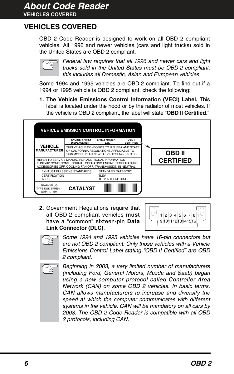
#### VEHICLES COVERED VEHICLES COVERED
OBD 2 Code Reader is designed to work on all OBD 2 compliant vehicles. All 1996 and newer vehicles (cars and light trucks) sold in the United States are OBD 2 compliant.
Federal law requires that all 1996 and newer cars and light trucks sold in the United States must be OBD 2 compliant; this includes all Domestic, Asian and European vehicles.
Some 1994 and 1995 vehicles are OBD 2 compliant. To find out if a 1994 or 1995 vehicle is OBD 2 compliant, check the following:
||VEHICLE MANUFACTURER|VEHICLE MANUFACTURER|ENGINE FAMILY EFN2.6YBT2BA DISPLACEMENT 2.6L|ENGINE FAMILY EFN2.6YBT2BA DISPLACEMENT 2.6L|OBD II CERTIFIED| |---|---|---|---|---| |VEHICLE MANUFACTURER|VEHICLE MANUFACTURER|THIS VEHICLE CONFORMS TO U.S. EPA AND STATE OF CALIFORNIA REGULATIONS APPLICABLE TO 1999 MODEL YEAR NEW TLEV PASSENGER CARS.|THIS VEHICLE CONFORMS TO U.S. EPA AND STATE OF CALIFORNIA REGULATIONS APPLICABLE TO 1999 MODEL YEAR NEW TLEV PASSENGER CARS.|THIS VEHICLE CONFORMS TO U.S. EPA AND STATE OF CALIFORNIA REGULATIONS APPLICABLE TO 1999 MODEL YEAR NEW TLEV PASSENGER CARS.| |REFER TO SERVICE MANUAL FOR ADDITIONAL INFORMATION TUNE-UP CONDITIONS: NORMAL OPERATING ENGINE TEMPERATURE, ACCESSORIES OFF, COOLING FAN OFF, TRANSMISSION IN NEUTRAL|REFER TO SERVICE MANUAL FOR ADDITIONAL INFORMATION TUNE-UP CONDITIONS: NORMAL OPERATING ENGINE TEMPERATURE, ACCESSORIES OFF, COOLING FAN OFF, TRANSMISSION IN NEUTRAL|REFER TO SERVICE MANUAL FOR ADDITIONAL INFORMATION TUNE-UP CONDITIONS: NORMAL OPERATING ENGINE TEMPERATURE, ACCESSORIES OFF, COOLING FAN OFF, TRANSMISSION IN NEUTRAL|REFER TO SERVICE MANUAL FOR ADDITIONAL INFORMATION TUNE-UP CONDITIONS: NORMAL OPERATING ENGINE TEMPERATURE, ACCESSORIES OFF, COOLING FAN OFF, TRANSMISSION IN NEUTRAL|REFER TO SERVICE MANUAL FOR ADDITIONAL INFORMATION TUNE-UP CONDITIONS: NORMAL OPERATING ENGINE TEMPERATURE, ACCESSORIES OFF, COOLING FAN OFF, TRANSMISSION IN NEUTRAL| |EXHAUST EMISSIONS STANDARDS STANDARD CATEGORY CERTIFICATION IN-USE
TLEV TLEV INTERMEDIATE|EXHAUST EMISSIONS STANDARDS STANDARD CATEGORY CERTIFICATION IN-USE
TLEV TLEV INTERMEDIATE|EXHAUST EMISSIONS STANDARDS STANDARD CATEGORY CERTIFICATION IN-USE
TLEV TLEV INTERMEDIATE|EXHAUST EMISSIONS STANDARDS STANDARD CATEGORY CERTIFICATION IN-USE
TLEV TLEV INTERMEDIATE|EXHAUST EMISSIONS STANDARDS STANDARD CATEGORY CERTIFICATION IN-USE
TLEV TLEV INTERMEDIATE| |SPARK PLUG TYPE NGK BPRE-11 GAP: 1.1MM|CATALYST|CATALYST| | |
VEHICLE EMISSION CONTROL INFORMATION
|OBD II CERTIFIED| |---| | |---|
||1|2|3|4|5|6|7|8| |---|---|---|---|---|---|---|---| |9|0|1|2|3|4|5|6| | |---|
Some 1994 and 1995 vehicles have 16-pin connectors but are not OBD 2 compliant. Only those vehicles with a Vehicle Emissions Control Label stating “OBD II Certified” are OBD 2 compliant.
Beginning in 2003, a very limited number of manufacturers (including Ford, General Motors, Mazda and Saab) began using a new computer protocol called Controller Area Network (CAN) on some OBD 2 vehicles. In basic terms, CAN allows manufacturers to increase and diversify the speed at which the computer communicates with different systems in the vehicle. CAN will be mandatory on all cars by 2008. The OBD 2 Code Reader is compatible with all OBD 2 protocols, including CAN.
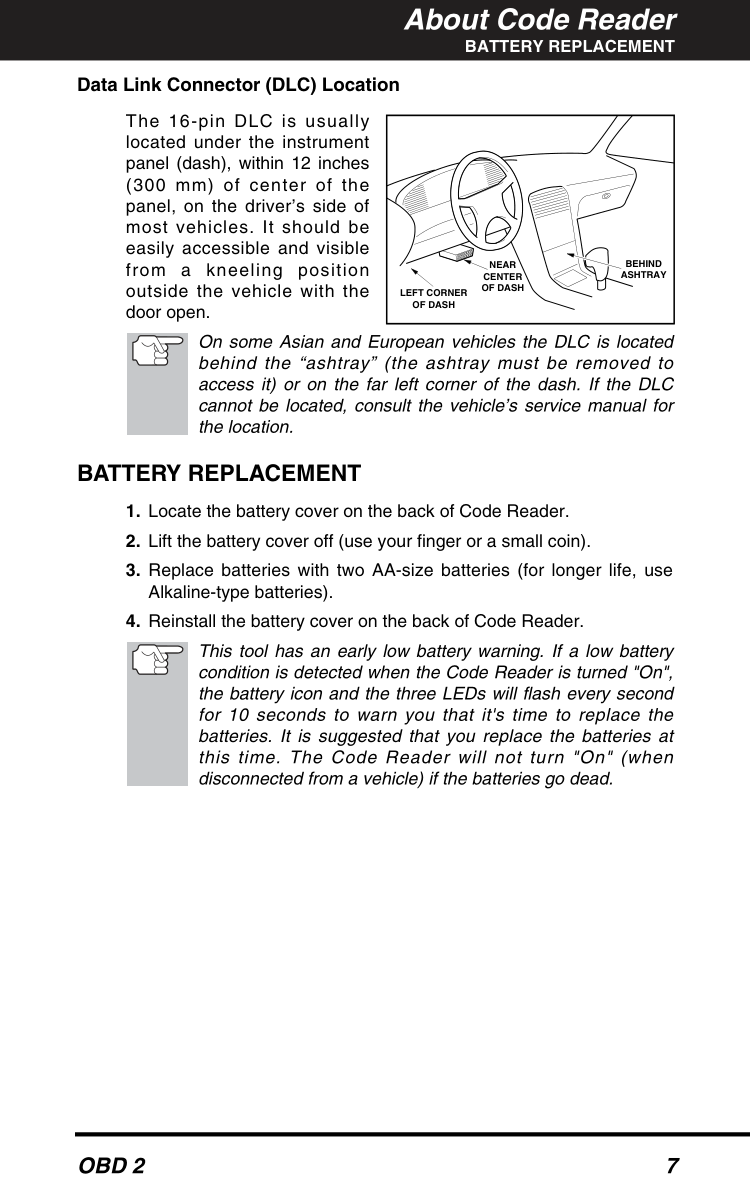
########## BATTERY REPLACEMENT Data Link Connector (DLC) Location
The 16-pin DLC is usually located under the instrument panel (dash), within 12 inches (300 mm) of center of the panel, on the driver’s side of most vehicles. It should be easily accessible and visible from a kneeling position outside the vehicle with the door open.
|NEAR CENTER OF DASH
BEHIND ASHTRAY LEFT CORNER OF DASH
|

|---|
On some Asian and European vehicles the DLC is located behind the “ashtray” (the ashtray must be removed to access it) or on the far left corner of the dash. If the DLC cannot be located, consult the vehicle’s service manual for the location.
#### BATTERY REPLACEMENT
This tool has an early low battery warning. If a low battery condition is detected when the Code Reader is turned "On", the battery icon and the three LEDs will flash every second for 10 seconds to warn you that it's time to replace the batteries. It is suggested that you replace the batteries at this time. The Code Reader will not turn "On" (when disconnected from a vehicle) if the batteries go dead.
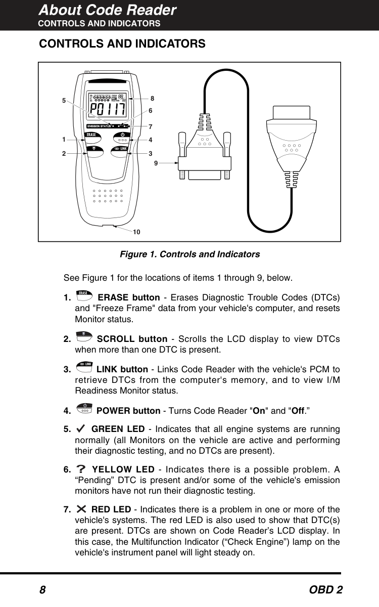
#### CONTROLS AND INDICATORS CONTROLS AND INDICATORS
|1
5
2 9
10
4 3
7
6
8
| |---|
########### Figure 1. Controls and Indicators
See Figure 1 for the locations of items 1 through 9, below.
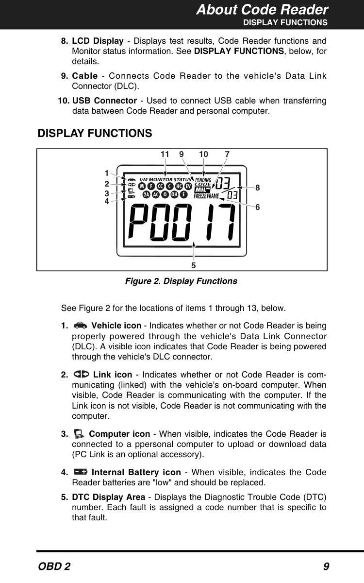
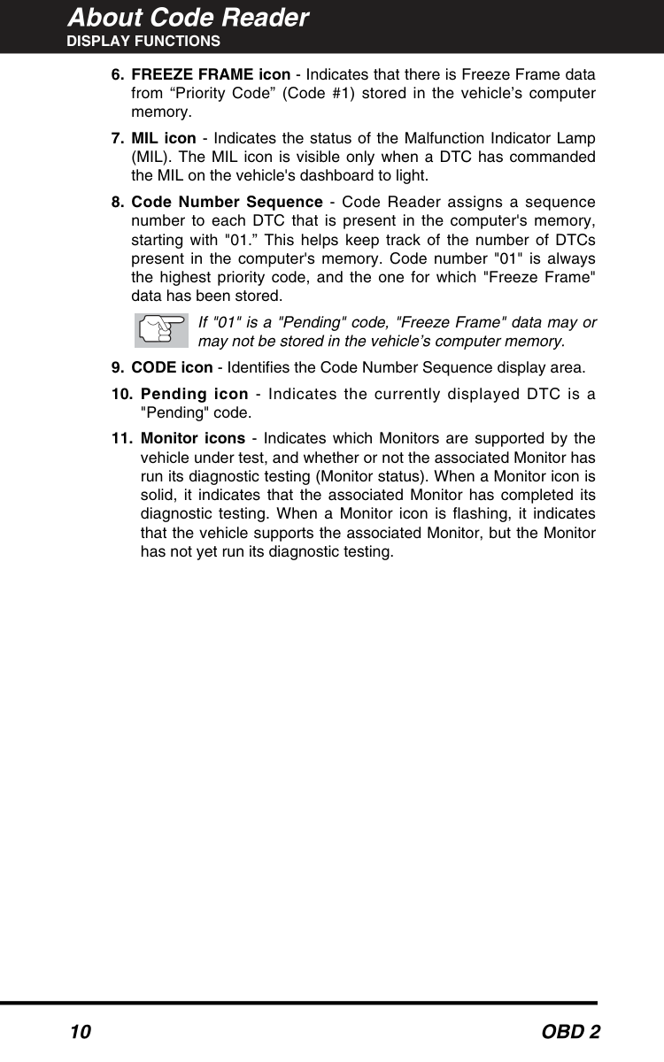
#### DISPLAY FUNCTIONS

|1
2
3
4
5
6
8
791011
| |---|
########### Figure 2. Display Functions
See Figure 2 for the locations of items 1 through 13, below.
############### DISPLAY FUNCTIONS
If "01" is a "Pending" code, "Freeze Frame" data may or may not be stored in the vehicle’s computer memory.
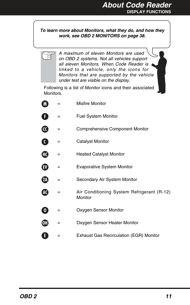
########### To learn more about Monitors, what they do, and how they work, see OBD 2 MONITORS on page 38.
A maximum of eleven Monitors are used on OBD 2 systems. Not all vehicles support all eleven Monitors. When Code Reader is linked to a vehicle, only the icons for Monitors that are supported by the vehicle under test are visible on the display.
Following is a list of Monitor icons and their associated Monitors.
= Misfire Monitor
= Fuel System Monitor
= Comprehensive Component Monitor
= Catalyst Monitor
= Heated Catalyst Monitor
= Evaporative System Monitor
= Secondary Air System Monitor
= Air Conditioning System Refrigerant (R-12) Monitor
= Oxygen Sensor Monitor
= Oxygen Sensor Heater Monitor
= Exhaust Gas Recirculation (EGR) Monitor
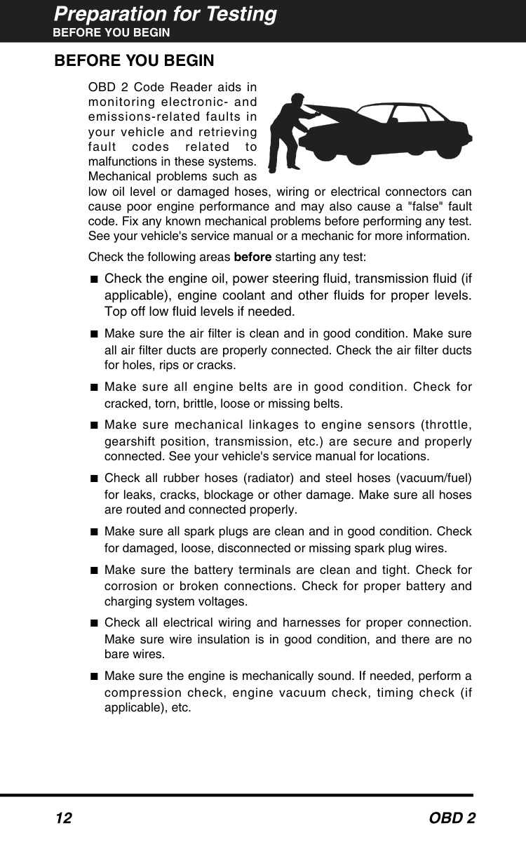
#### BEFORE YOU BEGIN BEFORE YOU BEGIN
OBD 2 Code Reader aids in monitoring electronic- and emissions-related faults in your vehicle and retrieving fault codes related to malfunctions in these systems. Mechanical problems such as low oil level or damaged hoses, wiring or electrical connectors can cause poor engine performance and may also cause a "false" fault code. Fix any known mechanical problems before performing any test. See your vehicle's service manual or a mechanic for more information.
Check the following areas before starting any test:
#### VEHICLE SERVICE MANUALS VEHICLE SERVICE MANUALS
Always refer to the manufacturer's service manual for your vehicle before performing any test or repair procedures. Contact your local car dealership, auto parts store or bookstore for availability of these manuals. The following companies publish valuable repair manuals:

############# FACTORY SOURCES
Ford, GM, Chrysler, Honda, Isuzu, Hyundai and Subaru Service Manuals
■ Helm Inc. 14310 Hamilton Avenue Highland Park, Michigan 48203 Phone: 800-782-4356
#### PRELIMINARY VEHICLE DIAGNOSIS WORKSHEET
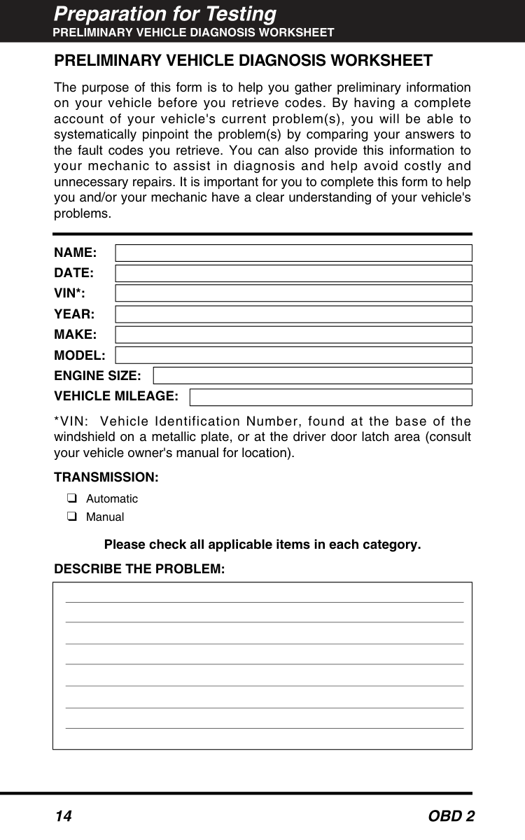
The purpose of this form is to help you gather preliminary information on your vehicle before you retrieve codes. By having a complete account of your vehicle's current problem(s), you will be able to systematically pinpoint the problem(s) by comparing your answers to the fault codes you retrieve. You can also provide this information to your mechanic to assist in diagnosis and help avoid costly and unnecessary repairs. It is important for you to complete this form to help you and/or your mechanic have a clear understanding of your vehicle's problems.
NAME: DATE: VIN*: YEAR: MAKE: MODEL: ENGINE SIZE: VEHICLE MILEAGE:
*VIN: Vehicle Identification Number, found at the base of the windshield on a metallic plate, or at the driver door latch area (consult your vehicle owner's manual for location).
########## TRANSMISSION:
❑ Automatic
❑ Manual
########## Please check all applicable items in each category. DESCRIBE THE PROBLEM:
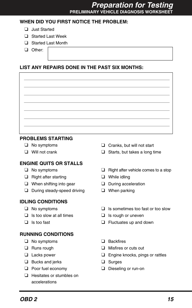
########## WHEN DID YOU FIRST NOTICE THE PROBLEM:
❑ Just Started
❑ Started Last Week ❑ Started Last Month ❑ Other:
LIST ANY REPAIRS DONE IN THE PAST SIX MONTHS:
PROBLEMS STARTING
❑ No symptoms ❑ Will not crank
❑ Cranks, but will not start
❑ Starts, but takes a long time
ENGINE QUITS OR STALLS
❑ No symptoms
❑ Right after vehicle comes to a stop
❑ Right after starting
❑ While idling
❑ When shifting into gear
❑ During acceleration
❑ During steady-speed driving
❑ When parking
IDLING CONDITIONS
❑ No symptoms
❑ Is sometimes too fast or too slow
❑ Is too slow at all times
❑ Is rough or uneven
❑ Is too fast
❑ Fluctuates up and down
RUNNING CONDITIONS
❑ No symptoms
❑ Backfires
❑ Runs rough
❑ Misfires or cuts out
❑ Lacks power
❑ Engine knocks, pings or rattles
❑ Bucks and jerks
❑ Surges
❑ Poor fuel economy
❑ Dieseling or run-on
❑ Hesitates or stumbles on
accelerations
AUTOMATIC TRANSMISSION PROBLEMS (if applicable)
❑ No symptoms
❑ Vehicle does not move when in
❑ Shifts too early or too late ❑ Changes gear incorrectly
gear
❑ Jerks or bucks
PROBLEM OCCURS
❑ Morning ❑ Afternoon ❑ Anytime ENGINE TEMPERATURE WHEN PROBLEM OCCURS
❑ Cold ❑ Warm ❑ Hot DRIVING CONDITIONS WHEN PROBLEM OCCURS
❑ Short - less than 2 miles
❑ With headlights on
❑ 2 - 10 miles
❑ During acceleration
❑ Long - more than 10 miles
❑ Mostly driving downhill
❑ Stop and go
❑ Mostly driving uphill
❑ While turning ❑ While braking ❑ At gear engagement
❑ Mostly driving level
❑ Mostly driving curvy roads ❑ Mostly driving rough roads
❑ With A/C operating
DRIVING HABITS
❑ Mostly city driving
❑ Drive less than 10 miles per day
❑ Highway
❑ Drive 10 to 50 miles per day
❑ Park vehicle inside
❑ Drive more than 50 miles per day
❑ Park vehicle outside
GASOLINE USED
❑ 87 Octane ❑ 89 Octane
❑ 91 Octane
❑ More than 91 Octane
WEATHER CONDITIONS WHEN PROBLEM OCCURS
❑ 32 - 55° F (0 - 13° C)
❑ Above 55° F (13° C)
❑ Below freezing (32° F / 0° C)
CHECK ENGINE LIGHT / DASH WARNING LIGHT
❑ Sometimes ON ❑ Always ON ❑ Never ON PECULIAR SMELLS
❑ "Hot"
❑ Gasoline
❑ Sulfur ("rotten egg")
❑ Burning oil
❑ Burning rubber
❑ Electrical
STRANGE NOISES
❑ Rattle ❑ Knock
❑ Squeak
❑ Other
#### CODE RETRIEVAL PROCEDURE
########### Retrieving and using Diagnostic Trouble Codes (DTCs) for troubleshooting vehicle operation is only one part of an overall diagnostic strategy.
Never replace a part based only on the DTC definition. Each DTC has a set of testing procedures, instructions and flow charts that must be followed to confirm the location of the problem. This information is found in the vehicle's service manual. Always refer to the vehicle's service manual for detailed testing instructions.
Check your vehicle thoroughly before performing any test. See Preparation for Testingon page 12 for details.
ALWAYSobserve safety precautions whenever working on a vehicle. See Safety Precautionson page 4 for more information.
Some DLCs have a plastic cover that must be removed before connecting the Code Reader cable connector.
| | |---|
If you still have problems, check the DLC on the vehicle and on the Code Reader. Refer to your vehicle's service manual to properly check the vehicle's DLC.
| | |---|
############### CODE RETRIEVAL PROCEDURE
■ If the Code Reader does not turn on automatically when connected to the vehicle, it indicates that there is no power at the vehicle's DLC. Check your fuse panel and replace any burned-out fuses.
If replacing the fuse(s) does not correct the problem, consult your vehicle's repair manual to locate the proper computer (PCM) fuse/circuit. Perform any necessary repairs before continuing.
engine.
If the ignition key is not turned "ON" within 10 seconds after the Code Reader is connected to a vehicle, an “Error” message will show on the Code Reader's LCD display. At times, an error message may display after you turn the ignition key on. If this happens, wait for the Code Reader to automatically re-link to the vehicle's computer.
|| | |---| | |---|
|| | |---| | |---|
If the Code Reader is interrupted or disconnected during code retrieval procedure, the screen will display "Error".
display and the green, yellow and red LEDs.
The green, yellow and red LEDs are used (with the LCD display) as visual aids to make it easier for the user to determine engine system conditions.
PENDING CODE PRESENT - If the yellow LED is lit, it may indicate the existence of a pending code. Check Code Reader’s LCD display for confirmation. A pending code is confirmed by the presence of a numeric code and the word PENDING on Code Reader’s LCD display. If no pending code is shown, the yellow LED indicates Monitor Status (see the following). See DIAGNOSTIC TROUBLE CODES (DTCs) on page 35 for more information about pending codes.
MONITOR STATUS - If Code Reader’s LCD display shows a zero (indicating there are no DTCs present in the vehicle's computer), but the yellow LED is lit, it indicates a "Monitor Has Not Run" status. This means that some of the Monitors on the vehicle have not yet finished their diagnostic self-testing. This condition is confirmed by one or more blinking Monitor icons on the LCD display. A blinking Monitor icon means the Monitor has not yet run and finished its diagnostic self-testing. All Monitor icons that are solid have completed their diagnostic self-testing.
For more information on Monitors, see “OBD 2 Monitors” on page 38.
Code Reader will automatically re-link to the vehicle's computer every 15 seconds to refresh the data being retrieved. When data is being refreshed, a single beep will sound, and "rEAd" will be shown on the LCD display for 5-6 seconds. Code Reader will then beep twice and return to displaying codes. This action repeats as long as Code Reader is in communication with the vehicle's computer.
Code Reader will display a code only if codes are present in the vehicle's computer memory. If no codes are present, a "0" will be displayed. Code Reader is capable of retrieving and storing up to 32 codes in memory, for immediate or later viewing.
############### ERASING DIAGNOSTIC TROUBLE CODES (DTCs)
■ Whenever the SCROLL function is used to view additional codes, Code Reader's communication link with the vehicle's computer disconnects. To re-establish communication, press the LINK button again.
Freeze Frame data is always associated with the “Priority Code” (identified as Code #1 in the Code Reader’s display). If the FREEZE FRAMEicon is lit when the “Priority Code” (Code #1) is displayed on the Code Reader’s screen, it indicates that there is Freeze Frame data associated with this code, and the vehicle’s computer has saved it in its memory.
Refer to page 45 for Diagnostic Trouble Code definitions. Match the retrieved DTC(s) with those listed. Read the associated definition(s), and see the vehicle's service manual for further evaluation.
#### ERASING DIAGNOSTIC TROUBLE CODES (DTCs)
########### When Code Reader’s ERASE function is used to erase the DTCs from the vehicle's on-board computer, "Freeze Frame" data and manufacturer-specific enhanced data are also erased.
If you plan to take the vehicle to a Service Center for repair, DO NOT erase the codes from the vehicle's computer. If the codes are erased, valuable information that might help the technician troubleshoot the problem will also be erased.
Erase DTCs from the computer's memory as follows:
When DTCs are erased from the vehicle's computer memory, the I/M Readiness Monitor Status program resets status of all the Monitors to a not run "flashing" condition. To set all of the Monitors to a DONE status, an OBD 2 Drive Cycle must be performed. Refer to your vehicle's service manual for information on how to perform an OBD 2 Drive Cycle for the vehicle under test.
| | |---|
| | |---|
LINK button to return to the code retrieval function.
| | |---|
| | |---|
Erasing DTCs does not fix the problem(s) that caused the code(s) to be set. If proper repairs to correct the problem that caused the code(s) to be set are not made, the code(s) will appear again (and the check engine light will illuminate) as soon as the vehicle is driven long enough for its Monitors to complete their testing.
#### I/M READINESS TESTING
I/M is an Inspection and Maintenance program legislated by the Government to meet federal clean-air standards.
The program requires that a vehicle be taken periodically to an Emissions Station for an "Emissions Test" or "Smog Check,” where the emissions-related components and systems are inspected and tested for proper operation. Emissions Tests are generally performed once a year, or once every two years.
On OBD 2 systems, the I/M program is enhanced by requiring vehicles to meet stricter test standards. One of the tests instituted by the Federal Government is called I/M 240. On I/M 240, the vehicle under test is driven under different speeds and load conditions on a dynamometer for 240 seconds, while the vehicle's emissions are measured.
Emissions tests vary depending on the geographic or regional area in which the vehicle is registered. If the vehicle is registered in a highly urbanized area, the I/M 240 is probably the type of test required. If the vehicle is registered in a rural area, the stricter “dynamometer type” test may not be required.
#### I/M Readiness Monitors
I/M Readiness shows whether the various emissions-related systems on the vehicle are operating properly and are ready for Inspection and Maintenance testing.
State and Federal Governments enacted Regulations, Procedures and Emission Standards to ensure that all emissions-related components and systems are continuously or periodically monitored, tested and diagnosed whenever the vehicle is in operation. It also requires vehicle manufacturers to automatically detect and report any problems or faults that may increase the vehicle's emissions to an unacceptable level.
The vehicle's emissions control system consists of several components or sub-systems (Oxygen Sensor, Catalytic Converter, EGR, Fuel System, etc.) that aid in reducing vehicle emissions.
To have an efficient Vehicle Emission Control System, all the emissions-related components and systems must work correctly whenever the vehicle is in operation.
To comply with State and Federal Government regulations, vehicle manufacturers designed a series of special computer programs called "Monitors" that are programmed into the vehicle's computer. Each of these Monitors is specifically designed to run tests and diagnostics on a specific emissions-related component or system (Oxygen Sensor, Catalytic Converter, EGR Valve, Fuel System, etc.) to ensure their proper operation. Currently, there are a maximum of eleven Monitors available for use.
########### To learn more about Emissions Inspection and Maintenance (I/M) Readiness Monitors, see OBD 2 MONITORS on page 38.
Each Monitor has a specific function to test and diagnose onlyits designated emissionsrelated component or system. The names of the Monitors (Oxygen Sensor Monitor, Catalyst Monitor, EGR Monitor, Misfire Monitor, etc.) describe which component or system each Monitor is designed to test and diagnose.
########## Emissions Inspection and Maintenance (I/M) Readiness Monitor Status Information
I/M Readiness Monitor Status shows which of the vehicle's Monitors have run and completed their diagnosis and testing, and which ones have not yet run and completed testing and diagnosis of their designated sections of the vehicle's emissions system.

The Monitor Run/Not Run status does not show whether or not a problem exists in a system. Monitor status only indicates whether a particular Monitor has or has not run and performed the self-diagnosis and testing of its associated system.
########## Performing I/M Readiness Quick Check
When a vehicle first comes from the factory, all Monitors indicate a DONE status. This indicates that all Monitors have run and completed their diagnostic testing. The DONE status remains in the computer's memory, unless the Diagnostic Trouble Codes are erased or the vehicle's computer memory is cleared.
Code Reader allows you to retrieve Monitor/System Status Information to help you determine if the vehicle is ready for an Emissions Test (Smog Check). In addition to retrieving Diagnostic Trouble Codes, Code Reader also retrieves Monitor Run/Not Run
status. This information is very important since different areas of the state/country have different emissions laws and regulations concerning Monitor Run/Not Run status.
Before an Emissions Test (Smog Check) can be performed, your vehicle must meet certain rules, requirements and procedures legislated by the Federal and state (country) governments where you live.
Monitors with a "Has Run" status indicate that all the required conditions they needed to perform diagnosis and testing of their assigned engine area (system) have been met, and all diagnostic testing has completed successfully.
Monitors with a "Has Not Run" status have not yet met the conditions they need to perform diagnosis and testing of their assigned engine area (system), and have not been able to perform diagnostic testing on that system.
The green, yellow and red LEDs provide a quick way to help you determine if a vehicle is ready for an Emissions Test (Smog Check). Follow the instructions below to perform the Quick Check.
Perform the Code Retrieval Procedure as described on page 17, then interpret the LED indications as follows:
####### Interpreting I/M Readiness Test Results
| | |---|

From the code retrieval procedure, determine the status of each Monitor (a solid Monitor icon shows Monitor "Has Run" status, a flashing Monitor icon indicates "Has Not Run" status). Take this information to an emissions professional to determine (based on your test results) if your vehicle is ready for an Emissions Test (Smog Check).
| | |---|
| | |---|
| | |---|
If the Red LED was obtained, there is a definite problem present in the system(s). In these cases, you have the following options.
########## Using the I/M Readiness Monitor Status to Confirm a Repair
The I/M Readiness Monitor Status function can be used (after repair of a fault has been performed) to confirm that the repair has been performed correctly, and/or to check for Monitor Run Status. Use the following procedure to determine I/M Readiness Monitor Status:

Misfire, Fuel and Comprehensive Component Monitors run continuously and their icons will always be on solid, even after the erase function is performed.
If the vehicle needs to be driven in order to perform a Trip Drive Cycle, ALWAYS have a second person help you. One person should drive the vehicle while the other person observes the Monitor icons on Code Reader for Monitor RUN status. Trying to drive and observe Code Reader at the same time is dangerous, and could cause a serious traffic accident.
############### WHAT’S NEXT?
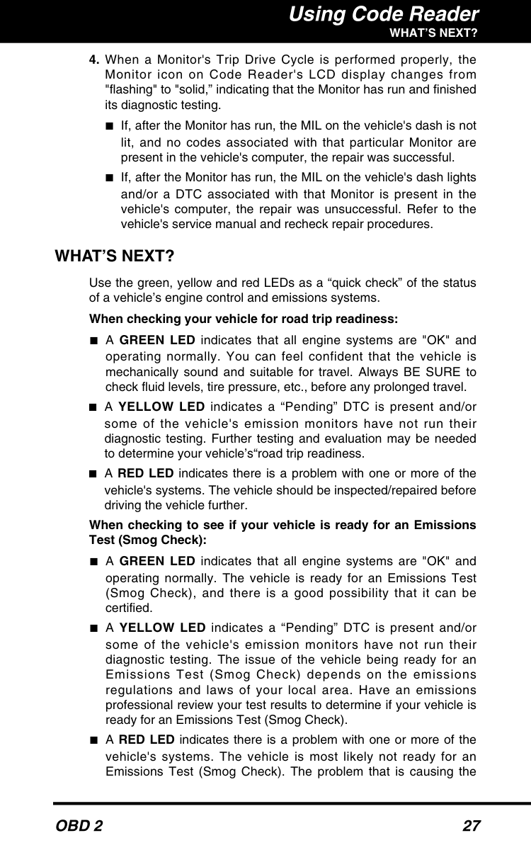
#### WHAT’S NEXT?
Use the green, yellow and red LEDs as a “quick check” of the status of a vehicle’s engine control and emissions systems.
############# When checking your vehicle for road trip readiness:
When checking to see if your vehicle is ready for an Emissions Test (Smog Check):
############### WHAT’S NEXT?
red LED to light must be repaired before an Emissions Test (Smog Check) can be performed. It is also suggested that the vehicle be inspected/repaired before driving the vehicle further.

############# When inspecting a used vehicle before buying or selling:
If no codes were retrieved and/or the green lights, and all your vehicle’s Monitors show a “Has Run” status, you’re “good to go.” You can feel confident that:
If codes were retrieved and/or the yellow or red LEDs light, you can choose to:
############ If the red LED lights after retrieving codes or performing an I/M Readiness inspection, it is suggested that the vehicle be inspected/repaired before driving the vehicle further.
#### COMPUTER ENGINE CONTROLS The Introduction of Electronic Engine Controls
########### Electronic Computer Control Systems make it possible for vehicle manufacturers to comply with the tougher emissions and fuel efficiency standards mandated by State and Federal Governments.
As a result of increased air pollution (smog) in large cities, such as Los Angeles, the California Air Resources Board (CARB) and the Environmental Protection Agency (EPA) set new regulations and air pollution standards to deal with the problem. To further complicate matters, the energy crisis of the early 1970s caused a sharp increase in fuel prices over a short period. As a result, vehicle manufacturers were not only required to comply with the new emissions standards, they also had to make their vehicles more fuelefficient. Most vehicles were required to meet a miles-per-gallon (MPG) standard set by the U.S. Federal Government.
Precise fuel delivery and spark timing are needed to reduce vehicle emissions. Mechanical engine controls in use at the time (such as ignition points, mechanical spark advance and the carburetor) responded too slowly to driving conditions to properly control fuel delivery and spark timing. This made it difficult for vehicle manufacturers to meet the new standards.
A new Engine Control System had to be designed and integrated with the engine controls to meet the stricter standards. The new system had to:
Vehicle Computer Control Systems can perform millions of calculations each second. This makes them an ideal substitute for the slower mechanical engine controls. By switching from mechanical to electronic engine controls, vehicle manufacturers are able to control fuel delivery and spark timing more precisely. Some newer Computer Control Systems also provide control over other vehicle functions, such as transmission, brakes, charging, body, and suspension systems.
########## The Basic Engine Computer Control System

############# The Computer Control System consists of an on-board computer and several related control devices (sensors, switches, and actuators).
The on-board computer is the heart of the Computer Control System. The computer contains several programs with preset reference values for air/fuel ratio, spark or ignition timing, injector pulse width, engine speed, etc. Separate values are provided for various driving conditions, such as idle, low speed driving, high-speed driving, low load, or high load. The preset reference values represent the ideal air/fuel mixture, spark timing, transmission gear selection, etc., for any driving condition. These values are programmed by the vehicle manufacturer, and are specific to each vehicle model.
Most on-board computers are located inside the vehicle behind the dashboard, under the passenger's or driver's seat, or behind the right kick panel. However, some manufacturers may still position it in the engine compartment.
Vehicle sensors, switches, and actuators are located throughout the engine, and are connected by electrical wiring to the on-board computer. These devices include oxygen sensors, coolant temperature sensors, throttle position sensors, fuel injectors, etc. Sensors and switches are input devices. They provide signals representing current engine operating conditions to the computer. Actuators are output devices. They perform actions in response to commands received from the computer.
The on-board computer receives information inputs from sensors and switches located throughout the engine. These devices monitor critical engine conditions such as coolant temperature, engine speed, engine load, throttle position, air/fuel ratio etc.
########## TYPICAL COMPUTER CONTROL SYSTEM
OUTPUT DEVICES Fuel Injectors Idle Air Control EGR Valve Ignition Module
################## On-Board Computer
INPUT DEVICES Coolant Temperature Sensor Throttle Position Sensor Fuel Injectors
################## INPUT DEVICES
Oxygen Sensors
The computer compares the values received from these sensors with its preset reference values, and makes corrective actions as needed so that the sensor values always match the preset reference values for the current driving condition. The computer makes adjustments by commanding other devices such as the fuel injectors, idle air control, EGR valve or Ignition Module to perform these actions.
Vehicle operating conditions are constantly changing. The computer continuously makes adjustments or corrections (especially to the air/fuel mixture and spark timing) to keep all the engine systems operating within the preset reference values.
########## On-Board Diagnostics - First Generation (OBD 1)
########### With the exception of some 1994 and 1995 vehicles, most vehicles from 1982 to 1995 are equipped with OBD 1 systems.
Beginning in 1988, California's Air Resources Board (CARB), and later the Environmental Protection Agency (EPA) required vehicle manufacturers to include a self-
diagnostic program in their on-board computers. The program would be capable of identifying emissions-related faults in a system. The first generation of Onboard Diagnostics came to be known as OBD 1.
OBD 1 is a set of self-testing and diagnostic instructions programmed into the vehicle's on-board computer. The programs are specifically designed to detect failures in the sensors, actuators, switches and wiring of the various vehicle emissions-related systems. If the computer detects a failure in any of these components or systems, it lights an indicator on the dashboard to alert the driver. The indicator lights only when an emissions-related problem is detected.
The computer also assigns a numeric code for each specific problem that it detects, and stores these codes in its memory for later retrieval. These codes can be retrieved from the computer's memory with the use of a "Code Reader" or a "Scan Tool.”
########## On-Board Diagnostics - Second Generation (OBD 2)
In addition to performing all the functions of the OBD 1 System, the OBD 2 System has been enhanced with new Diagnostic Programs. These programs closely monitor the functions of various emissions-related components and systems (as well as other systems) and make this information readily available (with the proper equipment) to the technician for evaluation.

########### The OBD 2 System is an enhancement of the OBD 1 System.
The California Air Resources Board (CARB) conducted studies on OBD 1 equipped vehicles. The information that was gathered from these studies showed the following:
To address the problems made evident by this study, CARB and the EPA passed new laws and standardization requirements. These laws required that vehicle manufacturers to equip their new vehicles with devices capable of meeting all of the new emissions standards and regulations. It was also decided that an enhanced on-board diagnostic system, capable of addressing all of these problems, was needed. This new system is known as "On-Board Diagnostics Generation Two (OBD 2).” The primary objective of the OBD 2 system is to comply with the latest regulations and emissions standards established by CARB and the EPA.
The Main Objectives of the OBD 2 System are:
########## OBD 2 Terminology
The following terms and their definitions are related to OBD 2 systems. Read and reference this list as needed to aid in the understanding of OBD 2 systems.
############ Not all vehicles support all eleven Monitors.
Do not confuse a "Trip" Drive Cycle with an OBD 2 Drive Cycle. A Trip Drive Cycle provides the "Enabling Criteria" for onespecific Monitor to run and complete its diagnostic testing. An OBD 2 Drive Cycle must meet the "Enabling Criteria" for allMonitors on a particular vehicle to run and complete their diagnostic testing.

#### DIAGNOSTIC TROUBLE CODES (DTCs)
Diagnostic Trouble Codes (DTCs) are meant to guide you to the proper service procedure in the vehicle's service manual. DO NOT replace parts based only on DTCs without first consulting the vehicle's service manual for proper testing procedures for that particular system, circuit or component.
########### Diagnostic Trouble Codes (DTCs) are codes that identify a specific problem area.
DTCs are alphanumeric codes that are used to identify a problem that is present in any of the systems that are monitored by the on-board computer (PCM). Each trouble code has an assigned message that identifies the circuit, component or system area where the problem was found.
OBD 2 diagnostic trouble codes are made up of five characters:
Generic DTCsare codes that are used by all vehicle manufacturers. The standards for generic DTCs, as well as their definitions, are set by the Society of Automotive Engineers (SAE).
Manufacturer-Specific DTCsare codes that are controlled by the vehicle manufacturer. The Federal Government does not require manufacturer-specific codes in order to comply with the new OBD 2 emissions standards. However, manufacturers are free to expand beyond the required codes to make their systems easier to diagnose.
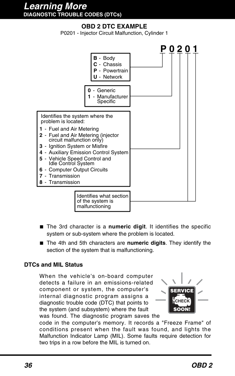
OBD 2 DTC EXAMPLE P0201 - Injector Circuit Malfunction, Cylinder 1
P 0 2 0 1
|B
C P U
-
Body Chassis Powertrain Network| | | |---|---|---| |B
C P U
-
Body Chassis Powertrain Network| | |
Identifies the system where the problem is located:

Fuel and Air Metering Fuel and Air Metering (injector circuit malfunction only) Ignition System or Misfire Auxiliary Emission Control System Vehicle Speed Control and Idle Control System Computer Output Circuits Transmission Transmission
Identifies what section of the system is malfunctioning
########## DTCs and MIL Status
When the vehicle's on-board computer detects a failure in an emissions-related component or system, the computer's internal diagnostic program assigns a diagnostic trouble code (DTC) that points to the system (and subsystem) where the fault was found. The diagnostic program saves the code in the computer's memory. It records a "Freeze Frame" of conditions present when the fault was found, and lights the Malfunction Indicator Lamp (MIL). Some faults require detection for two trips in a row before the MIL is turned on.
The "Malfunction Indicator Lamp" (MIL) is the accepted term used to describe the lamp on the dashboard that lights to warn the driver that an emissions-related fault has been found. Some manufacturers may still call this lamp a "Check Engine" or "Service Engine Soon” light.
There are two types of DTCs used for emissions-related faults: Type "A" and Type "B.” Type "A" codes are "One-Trip" codes; Type "B" DTCs are usually Two-Trip DTCs.

The MIL will stay lit for both Type "A" and Type "B" codes until one of the following conditions occurs:
After the MIL has been turned off, DTCs, Freeze Frame data, and manufacturer-specific enhanced data stay in the computer's memory. This data can only be retrieved by using equipment such as a Scan Tool.
#### OBD 2 MONITORS
To ensure the correct operation of the various emissions-related components and systems, a diagnostic program was developed and installed in the vehicle's on-board computer. The program has several procedures and diagnostic strategies. Each procedure or diagnostic strategy is made to monitor the operation of, and run diagnostic tests on, a specific emissions-related component or system. These tests ensure the system is running correctly and is within the manufacturer's specifications. On OBD 2 systems, these procedures and diagnostic strategies are called "Monitors.”
Currently, a maximum of eleven Monitors are used in OBD 2 systems. Additional monitors may be added as a result of Government regulations as the OBD 2 system grows and matures. Not all vehicles use all eleven Monitors.
Monitor operation is either "Continuous" or "Non-Continuous,” depending on the specific monitor.
############# Continuous Monitors
Three of these Monitors are designed to constantly monitor their associated components and/or systems for proper operation. Continuous Monitors run constantly when the engine is running. The Continuous Monitors are:
The other eight Monitors are "non-continuous" Monitors. "Noncontinuous" Monitors perform and complete their testing once per trip. The "non-continuous" Monitors are:

The following provides a brief explanation of the function of each Monitor:
Rationality: Each input signal is compared against all other inputs and against information in the computer's memory to see if it makes sense under the current operating conditions. Example: The signal from the throttle position sensor indicates the vehicle is in a wideopen throttle condition, but the vehicle is really at idle, and the idle condition is confirmed by the signals from all other sensors. Based on the input data, the computer determines that the signal from the throttle position sensor is not rational (does not make sense when compared to the other inputs). In this case, the signal would fail the rationality test.
The CCM may be either a "One-Trip" or a "Two-Trip" Monitor, depending on the component.
The Fuel System Monitor may be a "One-Trip" or "Two-Trip" Monitor, depending on the severity of the problem.
The computer checks the efficiency of the catalytic converter by monitoring the oxygen sensors used by the system. One sensor is located before (upstream of) the converter; the other is located after (downstream of) the converter. If the catalytic converter loses its ability to store oxygen, the downstream sensor signal voltage becomes almost the same as the upstream sensor signal. In this case, the monitor fails the test.
The Catalyst Monitor is a "Two-Trip" Monitor. If a fault is found on the first trip, the computer temporarily saves the fault in its memory as a Pending Code. The computer does not command the MIL on at this time. If the fault is sensed again on the second trip, the computer commands the MIL "On" and saves the code in its longterm memory.
The EGR Monitor is a "Two-Trip" Monitor. If a fault is found on the first trip, the computer temporarily saves the fault in its memory as a Pending Code. The computer does not command the MIL on at this time. If the fault is sensed again on the second trip, the computer commands the MIL "On,” and saves the code in its longterm memory.
Fumes are carried from the fuel tank to the charcoal canister by hoses or tubes. The fumes are stored in the charcoal canister. The computer controls the flow of fuel vapors from the charcoal canister to the engine via a purge solenoid. The computer energizes or deenergizes the purge solenoid (depending on solenoid design). The purge solenoid opens a valve to allow engine vacuum to draw the fuel vapors from the canister into the engine where the vapors are burned. The EVAP Monitor checks for proper fuel vapor flow to the engine, and pressurizes the system to test for leaks. The computer runs this Monitor once per trip.
The EVAP Monitor is a "Two-Trip" Monitor. If a fault is found on the first trip, the computer temporarily saves the fault in its memory as a Pending Code. The computer does not command the MIL on at this time. If the fault is sensed again on the second trip, the PCM commands the MIL "On,” and saves the code in its long-term memory.
############## ■ Air Conditioning (A/C) Monitor - The A/C Monitor senses leaksin air conditioning systems that utilize R-12 refrigerant. Vehiclemanufacturers have been given two options:
To date, all vehicle manufacturers have opted to use R-134 in their A/C systems. As a result, this Monitor has not yet been implemented.
############## ■ Oxygen Sensor Heater Monitor - The Oxygen Sensor HeaterMonitor tests the operation of the oxygen sensor's heater. Thereare two modes of operation on a computer-controlled vehicle:"open-loop" and "closed-loop.” The vehicle operates in open-loopwhen the engine is cold, before it reaches normal operatingtemperature. The vehicle also goes to open-loop mode at othertimes, such as heavy load and full throttle conditions. When thevehicle is running in open-loop, the oxygen sensor signal isignored by the computer for air/fuel mixture corrections. Engineefficiency during open-loop operation is very low, and results in theproduction of more vehicle emissions.
Closed-loop operation is the best condition for both vehicle emissions and vehicle operation. When the vehicle is operating in closed-loop, the computer uses the oxygen sensor signal for air/fuel mixture corrections.
In order for the computer to enter closed-loop operation, the oxygen sensor must reach a temperature of at least 600°F. The oxygen sensor heater helps the oxygen sensor reach and maintain its minimum operating temperature (600° F) more quickly, to bring the vehicle into closed-loop operation as soon as possible.
The Oxygen Sensor Heater Monitor is a "Two-Trip" Monitor. If a fault is found on the first trip, the computer temporarily saves the fault in its memory as a Pending Code. The computer does not command the MIL on at this time. If the fault is sensed again on the second trip, the computer commands the MIL "On,” and saves the code in its long-term memory.
############## ■ Oxygen Sensor Monitor - The Oxygen Sensor monitors how muchoxygen is in the vehicle's exhaust. It generates a varying voltage ofup to one volt, based on how much oxygen is in the exhaust gas,and sends the signal to the computer. The computer uses this signalto make corrections to the air/fuel mixture. If the exhaust gas has alarge amount of oxygen (a lean air/fuel mixture), the oxygen sensorgenerates a "low" voltage signal. If the exhaust gas has very littleoxygen (a rich mixture condition), the oxygen sensor generates a"high" voltage signal. A 450mV signal indicates the most efficient,and least polluting, air/fuel ratio of 14.7 parts of air to one part of fuel.
The oxygen sensor must reach a temperature of at least 600650°F, and the engine must reach normal operating temperature, for the computer to enter into closed-loop operation. The oxygen sensor only functions when the computer is in closed-loop. A properly operating oxygen sensor reacts quickly to any change in oxygen content in the exhaust stream. A faulty oxygen sensor reacts slowly, or its voltage signal is weak or missing.
The oxygen sensor is a "Two-Trip" monitor. If a fault is found on the first trip, the computer temporarily saves the fault in its memory
The Secondary Air System Monitor checks for component integrity and system operation, and tests for faults in the system. The computer runs this Monitor once per trip.
The Secondary Air System Monitor is a "Two-Trip" monitor. If a fault is found on the first trip, the computer temporarily saves this fault in its memory as a Pending Code. The computer does not command the MIL on at this time. If the fault is sensed again on the second trip, the computer commands the MIL "On,” and saves the code in its long-term memory.
########## OBD 2 Reference Table
The table below lists current OBD 2 Monitors, and indicates the following for each Monitor:
|Name of Monitor|A|B|C|D|E|F| |---|---|---|---|---|---|---| |Comprehensive Component Monitor|Continuous|1|2|1|3
|4| |Misfire Monitor (Type 1 and 3)
|Continuous|1|2|1|3 - similar conditions|80| |Misfire Monitor (Type 2)|Continuous| |1
| |3 - similar conditions|80| |Fuel System Monitor|Continuous|1|1 or 2|1
|3 - similar conditions|80| |Catalytic Converter Monitor
|Once per trip|1|2|1|3 trips|40| |Oxygen Sensor Monitor
|Once per trip|1|2|1|3 trips|40| |Oxygen Sensor Heater Monitor|Once per trip|1|2|1
|3 trips|40| |Exhaust Gas Recirculation (EGR) Monitor|Once per trip|1
|2|1|3 trips|40| |Evaporative Emissions Controls Monitor|Once per trip|1|2|1|3 trips|40
| |Secondary Air System (AIR) Monitor|Once per trip|1|2|1|3 trips|40|
#### DIAGNOSTIC TROUBLE CODE DEFINITIONS DIAGNOSTIC TROUBLE CODE DEFINITIONS
This section provides the most complete lists of DTC definitions available at the time of publication. OBD 2 is an evolving system; new codes and definitions are added as the system grows. ALWAYS check your vehicle's service manual for code definitions that are not listed here.This section contains both "Generic" and "Manufacturer Specific" DTC definitions:
This manual provides "Manufacturer Specific" DTC definitions for CHRYSLER, FORD, GENERAL MOTORS, HONDA and TOYOTAonly. For DTC definitions that are not in these lists, and/or for Body, Chassis and Network DTC definitions, reference your vehicle's service manual.
#### GENERIC (P0010 - P0057) GENERIC DTC DEFINITIONS
########## Code Definition

P0015 "B" Camshaft Position - Timing Over-Retarded (Bank 1)
Performance (Bank 2)


GENERIC (P0107 - P0136)
########## Code Definition


GENERIC (P0171 - P0204)
########## Code Definition

GENERIC (P0205 - P0236) Code Definition
GENERIC (P0237 - P0270)
########## Code Definition


GENERIC (P0307 - P0344)
########## Code Definition

GENERIC (P0345 - P0377) Code Definition


GENERIC (P0378 - P0415)
########## Code Definition


GENERIC (P0416 - P0445) Code Definition
GENERIC (P0446 - P0473)
########## Code Definition

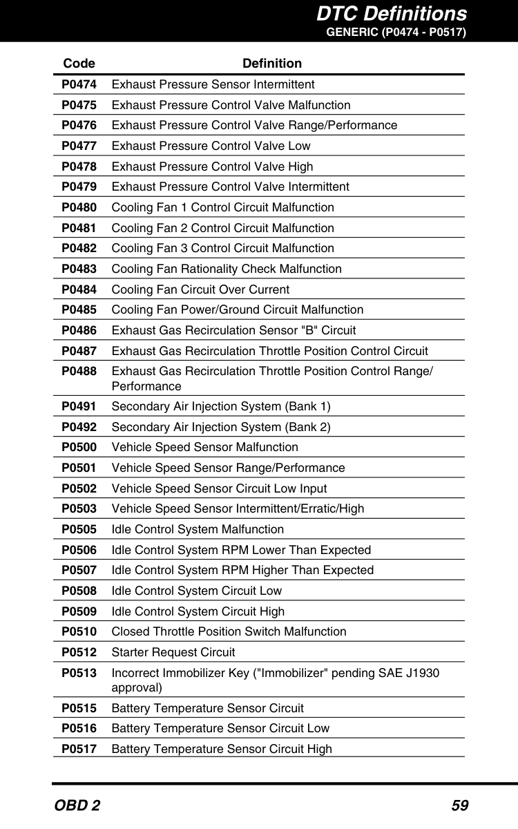
GENERIC (P0474 - P0517) Code Definition


GENERIC (P0520 - P0569)
########## Code Definition


GENERIC (P0636 - P0711)
########## Code Definition


GENERIC (P0747 - P0780)
########## Code Definition


GENERIC (P0817 - P0849)
########## Code Definition

#### CHRYSLER (P1103 - P1389) MANUFACTURER SPECIFIC CODES - CHRYSLER
########## Code Definition


CHRYSLER (P1390 - P1596)
########## Code Definition


#### FORD (P1000 - P1133) MANUFACTURER SPECIFIC CODES - FORD
########## Code Definition


FORD (P1188 - P1232)
########## Code Definition

FORD (P1233 - P1271) Code Definition

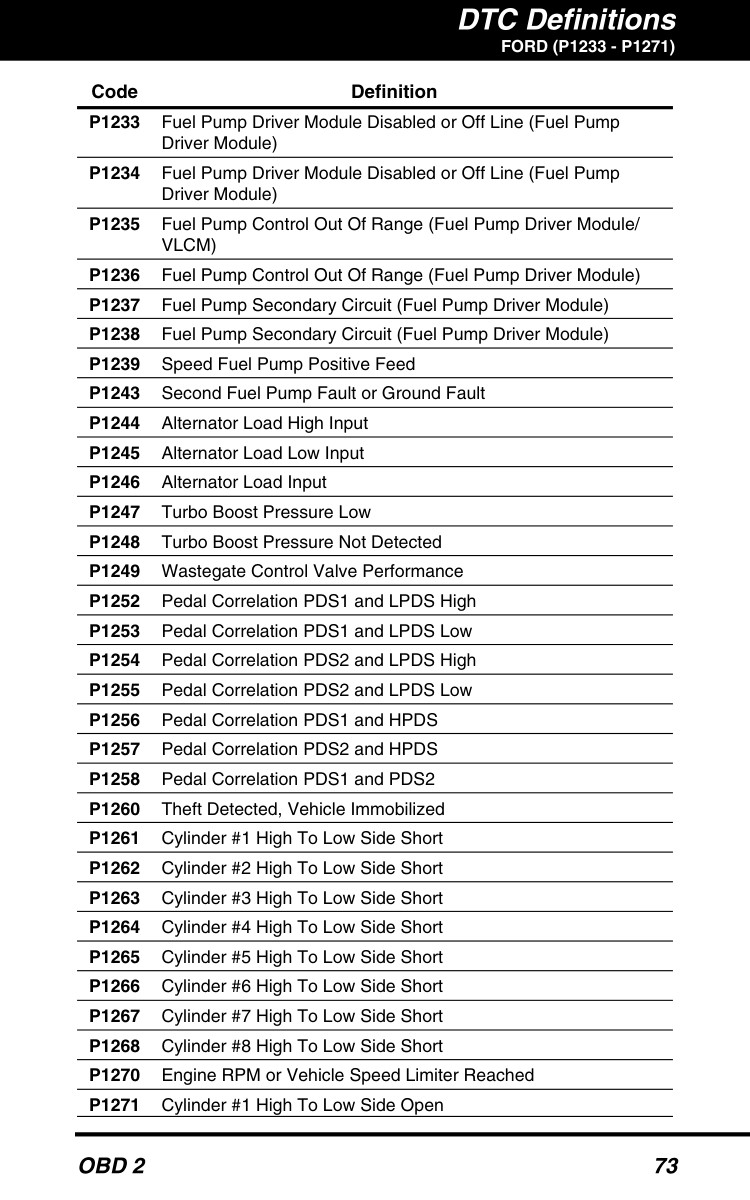
FORD (P1272 - P1306)
########## Code Definition


FORD (P1401 - P1469)
########## Code Definition

P1431 Misfire Monitor Disabled, Unable to Learn Trigger Wheel
Profile
P1455 Evaporative Emission Control System Control Leak Detected
(gross leak/no flow)
P1457 Unable to Pull Fuel Tank Vacuum

FORD (P1473 - P1566) Code Definition

FORD (P1567 - P1625)
########## Code Definition


P1709 Park Neutral Position Switch Out Of Self Test Range
FORD (P1717 - P1785)
########## Code Definition


P1822 Transfer Case LO To HI Shift Relay Coil Short To Battery P1824 4-Wheel Drive Electric Clutch Relay Open Or Short To Ground P1826 4-Wheel Drive Electric Clutch Relay Short To Battery P1828 Transfer Case HI To LO Shift Relay Coil Circuit Open Or Short
To Ground P1830 Transfer Case HI To LO Shift Relay Coil Circuit Short To Battery P1832 Transfer Case 4-Wheel Drive Solenoid Circuit Open or Short To
Ground P1834 Transfer Case 4-Wheel Drive Solenoid Circuit Short To Battery P1838 No Shift Motor Movement Detected P1846 Transfer Case Contact Plate ‘A’ Circuit Open P1850 Transfer Case Contact Plate ‘B’ Circuit Open P1854 Transfer Case Contact Plate ‘C’ Circuit Open P1858 Transfer Case Contact Plate ‘D’ Circuit Open
FORD (P1883 - P1901)
########## Code Definition

GENERAL MOTORS (P1031 - P1188)
#### MANUFACTURER SPECIFIC CODES - GENERAL MOTORS
Code Definition P1031 H02 Sensor Heater Control Circuit Problem P1106 MAP Sensor Circuit Intermittent High or Low Voltage P1107 MAP Sensor Circuit Intermittent Voltage Low P1108 BARO to MAP Signal Circuit Comparison Too High
P1158 HO2 Sensor Shift Rich (Bank 2 Sensor 2)/ Engine Metal
Over-Temperature Protection P1161 HO2 Sensor Heater Control Circuit (Bank 2 Sensor 2) P1171 Fuel System Lean During Acceleration P1187 Engine Oil Temperature Sensor Circuit Voltage Low (except
1997 Corvette)

############### GENERAL MOTORS (P1188 - P1320)
Code Definition P1188 Engine Oil Pressure Sensor Circuit Voltage High (1997 Corvette) P1189 Engine Oil Pressure Switch Circuit P1200 Injector Control Circuit

P1300 Ignition Coil 1 Primary Feedback Circuit P1305 Ignition Coil 2 Primary Feedback Circuit P1310 Ignition Coil 3 Primary Feedback Circuit P1315 Ignition Coil 4 Primary Feedback Circuit P1320 ICM 4X Reference Circuit Too Many Pulses (except 1996-98
4.0L)
P1320 ICM 4X Reference Circuit Intermittent No Pulses (1996-98
4.0L)
############### GENERAL MOTORS (P1323 - P1406)
Code Definition P1323 ICM 24X Reference Circuit Low Frequency P1335 Crankshaft Positioning Sensing Circuit P1336 CKP System Variation Not Learned
P1349 Intake Camshaft Position System P1350 Ignition Control System P1351 Ignition Control Circuit Voltage High (except 1998 3.1L)

############### GENERAL MOTORS (P1408 - P1527)
Code Definition P1408 MAP Sensor Circuit P1410 Fuel Tank Pressure System P1415 AIR System Bank 1 P1416 AIR System Bank 2


############### GENERAL MOTORS (P1530 - P1571)
Code Definition P1530 Ignition Timing Adjustment Switch Circuit
P1546 A/C Clutch Status Circuit Voltage Low (1996-98 Camaro/
Firebird & 1997-98 Corvette)
P1550 Stepper Motor Speed Control

P1564 Speed Control System/Vehicle Acceleration Too High
(except Catera)
############### GENERAL MOTORS (P1571 - P1610)
Code Definition P1571 Traction Control System PWM Circuit No Frequency (4.0L & 4.6L)

P1601 ECM Overtemperature P1602 Loss Of EBC/EBTCM Serial Data (Except Catera)

P1610 Loss Of PZM Serial Data (1996-97 Except 1997 Cutlass
& Malibu)
P1610 Failure With Body Function Controller (1997 Cutlass & Malibu)
############### GENERAL MOTORS (P1610 - P1642)
Code Definition P1610 Standard Body Module Series Data CKT (1998) P1611 Loss Of CVRTD Serial Data P1617 Engine Oil Level Switch Circuit

3.1L & 3.8L)
GENERAL MOTORS (P1642 - P1663)
########## Code Definition

P1651 Fan 1 Relay Control Circuit P1652 Fan 2 Relay Control Circuit (Except Cadillac & Corvette)
P1653 Fuel Level Output Control Circuit (1998 3.8L) P1654 A/C Relay Control Circuit (Except 4.0L & 4.6L)


P1740 Torque Management Request Circuits, Transmission &
Traction Control (Except Catera) P1740 Torque Control/Management Request Circuits (Catera) P1760 Transmission Control Module Supply Voltage Interrupted
P1792 ECM To Transmission Control Module Engine Coolant
Signal
P1800 ECM To Transmission Control Module Engine Coolant
Signal
GENERAL MOTORS (P1826 - P1895)
########## Code Definition
#### HONDA (P1106- P1382) MANUFACTURER SPECIFIC CODES - HONDA
Code Definition P1106 BARO Circuit Range/Performance P1107 BARO Circuit Low Input P1108 BARO Circuit High Input


############### HONDA (P1456 - P1687)
Code Definition P1456 EVAP Emission Control System Leak Detected (Fuel Tank
System)
P1457 EVAP Emission Control System Leak Detected (Control
Canister System) P1459 EVAP Emission Purge Flow Switch Malfunction P1491 EGR valve Lift Insufficient Detected P1498 EGR Valve Lift Sensor High Voltage P1508 IAC Valve Circuit Failure P1509 IAC Valve Circuit Failure P1519 Idle Air Control Valve Circuit Failure P1607 EGM/PGM Internal Circuit Failure A P1655 SEA/SEFA/TMA/TMB Signal Line Failure P1660 A/T FI Signal A Circuit Failure P1681 A/T FI Signal A Low Input P1682 A/T FI Signal A High Input P1686 A/T FI Signal B Low Input P1687 A/T FI Signal B Low Input
#### TOYOTA (P1100- P1346) MANUFACTURER SPECIFIC CODES - TOYOTA
Code Definition P1100 BARO Sensor Circuit malfunction P1120 Accelerator Pedal Position Sensor Circuit Malfunction P1121 Accelerator Pedal Position Sensor Range/Performance Problem
P1305 Igniter Circuit Malfunction No. 2 (1998-2000 Land Cruiser,

2000 Celica & Tundra)
P1315 Igniter Circuit Malfunction No. 4 (1998-2000 Land Cruiser,
2000 Celica & Tundra)
P1320 Igniter Circuit Malfunction No. 5 (1998-2000 Land Cruiser
& 2000 Tundra)
P1325 Igniter Circuit Malfunction No. 6 (1998-2000 Land Cruiser
& 2000 Tundra)
P1330 Igniter Circuit Malfunction No. 7 (1998-2000 Land
Cruiser & 2000 Tundra) P1335 No CKP Sensor Signal Engine Running P1340 Igniter Circuit Malfunction No. 8 (1998-2000 Land
Cruiser & 2000 Tundra)
P1346 VVT Sensor /Camshaft Position Sensor Circuit Range/
Performance Problem (Bank 1)
############### TOYOTA (P1349 - P1780)
Code Definition P1349 VVT System Malfunction P1400 Sub-Throttle Position Sensor Malfunction P1401 Sub-Throttle Position Sensor Range/Performance Problem P1405 Turbo Pressure Sensor Circuit Malfunction P1406 Turbo Pressure Sensor Range/Performance Problem P1410 EGR Valve Position Sensor Circuit Malfunction P1411 EGR Valve Position Sensor Circuit Ranger/Performance P1500 Starter Signal Circuit Malfunction P1510 Boost Pressure Control Circuit Malfunction P1511 Boost Pressure Low Malfunction P1512 Boost Pressure High Malfunction P1520 Stop Lamp Switch Signal Malfunction P1565 Cruise Control Main Switch Circuit Malfunction P1600 ECM BATT Malfunction P1605 Knock Control CPU Malfunction P1630 Traction Control System Malfunction P1633 ECM Malfunction ECTS Circuit P1645 Body ECU Malfunction P1652 IACV Control Circuit Malfunction P1656 OCV Circuit Malfunction P1658 Waste Gate Valve Control Circuit Malfunction P1661 EGR Circuit Malfunction P1662 EGR By-Pass Valve Control Circuit Malfunction P1690 OCV Circuit Malfunction P1692 OCV Open Malfunction P1693 OCV Closed Malfunction P1780 PNP Switch Malfunction
Glossary
#### GLOSSARY OF TERMS AND ABBREVIATIONS INTRODUCTION
This Glossary contains definitions for abbreviations and terms you may find in this manual or in your vehicle service manual.
GLOSSARY OF TERMS AND ABBREVIATIONS CARB – California Air Resources Board CCM – Central Control Module
Computer Control System – An electronic control system, consisting of an on-board computer and related sensors, switches and actuators, used to ensure peak performance and fuel efficiency while reducing pollutants in the vehicle’s emissions.
DIY – Do-It-Yourself DLC – Data Link Connector
Drive Cycle – An extended set of driving procedures that takes into consideration the various types of driving conditions encountered in real life.
Driving Condition – A specific environmental or operation condition under which a vehicle is operated; such as starting the vehicle when cold, driving at steady speed (cruising), accelerating, etc.
DTC(s) – Diagnostic Trouble Code(s) EGR – Exhaust Gas Recirculation EPA – Environmental Protection Agency EVAP – Evaporative Emissions System Fault Code – See DTCs
Freeze Frame – A digital representation of engine and/or emissions system conditions present when a fault code was recorded.
FTP – Fuel Tank Pressure Generic Code – A DTC that applies to all OBD 2 compliant vehicles.
I/M Readiness – An indication of whether or not a vehicle’s emissions-related system are operating properly and are ready for Inspection and Maintenance testing.
I/M Test / Emissions Test / Smog Check – A functional test of a vehicle to determine if tailpipe emissions are within Federal/State/Local requirements.
LCD – Liquid Crystal Display LED – Light Emitting Diode
GLOSSARY
############### GLOSSARY OF TERMS AND ABBREVIATIONS
Manufacturer Specific Code – A DTC that applies only to OBD 2 compliant vehicles made by a specific manufacturer.
MIL – Malfunction Indicator Lamp (also referred to as “Check Engine” light
OBD 1 – On-Board Diagnostics Version 1 (also referred to as
On-Board Computer – The central processing unit in the
vehicle’s computer control system. PCM – Powertrain Control Module
Pending Code – A code recorded on the “first trip” for a “two-trip” code. If the fault that caused the code to be set is not detected on the second trip, the code is automatically erased.
Trip Drive Cycle – Vehicle operation that provides the necessary driving condition to enable a vehicle Monitor to run and complete its diagnostic testing.
VECI – Vehicle Emission Control Information Decal
Warranty and Servicing
#### LIMITED ONE YEAR WARRANTY
The Manufacturer warrants to the original purchaser that this unit is free of defects in materials and workmanship under normal use and maintenance for a period of one (1) year from the date of original purchase.
If the unit fails within the one (1) year period, it will be repaired or replaced, at the Manufacturer’s option, at no charge, when returned prepaid to the Service Center with Proof of Purchase. The sales receipt may be used for this purpose. Installation labor is not covered under this warranty. All replacement parts, whether new or remanufactured, assume as their warranty period only the remaining time of this warranty.
This warranty does not apply to damage caused by improper use, accident, abuse, improper voltage, service, fire, flood, lightning, or other acts of God, or if the product was altered or repaired by anyone other than the Manufacturer’s Service Center.
The Manufacturer, under no circumstances shall be liable for any consequential damages for breach of any written warranty of this unit. This warranty gives you specific legal rights, and you may also have rights, which vary from state to state. This manual is copyrighted with all rights reserved. No portion of this document may be copied or reproduced by any means without the express written permission of the Manufacturer. THIS WARRANTY IS NOT TRANSFERABLE. For service, send via U.P.S. (if possible) prepaid to Manufacturer. Allow 3-4 weeks for service/repair.
#### SERVICE PROCEDURES
If you have any questions, require technical support or information on UPDATES and OPTIONAL ACCESSORIES, please contact your local store, distributor or the Service Center.
############# USA & Canada:
(800) 544-4124 (6:00 AM-6:00 PM, 7 days a week PST) All others: (714) 241-6802 (6:00 AM-6:00 PM, 7 days a week PST) FAX: (714) 432-3979 (24 hr.) Web: www.innova.com
www.innova.com
®
######## Innova Electronics Corp.
17352 Von Karman Ave. Irvine, CA 92614
Instruction MRP #93-0068 Rev. B
PRODUCT DESIGN & COPYRIGHT
© 2012