
Ask AI
— answers from the official manualAnswers from the official manual.
Common questions
Common Questions
8 totalHow do I attach and remove the seat of the Weider Pro 9645?
To attach: Set the bracket on Front Seat Frame onto pins on Front Upright. Fix with a Carriage Bolt (14) and Seat Knob (40). To Remove: Ensure chain is not attached to Leg Lever, remove Bolt and Knob then lift from upright.
How do I adjust the Leg Press Plate?
Remove Press Pin from Plate & Arm. Align welded tubes with desired holes on Arm then re-insert Press Pin through both components (Page 25).
What are the exact dimensions and assembled size of the Weider Pro 9645?
The assembled dimensions are 78 inches in height, 86 inches in width, and 66 inches in length (Page 3).
Can I lubricate or clean parts on the Weider Pro 9645?
Lubricate cables and pulley axles for smooth operation and use a damp cloth with mild non-abrasive detergent to keep surfaces clean (Page 25).
What should I do if one of the cables does not move smoothly after setup?
Pull each cable a few times to ensure they move smoothly over pulleys. If any cable is sluggish, identify and fix issues since improperly installed cables may be damaged during use (Page 23).
How can I tighten the High Cable if it has slack?
To remove slack from the High Cable, tighten the 1/4" Nylon Locknut that connects its end to the Small "U"Bracket. Similarly, move the 3 1/2" Pulleys to alternate holes in Long "U"Brackets to prevent cable slack.
Full Manual
31 pages

PATE:', _";;_'._HOING
V IDER
######### USER'S MANUAL
################## Model No. 831.159380 Serial No.
The serial number can be found in the location shown below. Write the serial number in the space above.
Seria{ Numbar Decal
I:" (_ U I p M E N T
I[_,,|1 | ;i-."B n _ i,.Si
H EI-,P LI N E !
1-800-73d-dg7P
SW/ARS
SEARS, ROEBUCK AND CO., HOFFMAN ESTATES, IL 60179

############ TABLE OF CONTENTS
IMPORTANT PRECAUTIONS .............................................................. 2 BEFORE YOU BEGIN ................................................................... 3 ASSEMBLY ..... °........................................................... 4 HOW TO USE THE HOME GYM SYSTEM .............................. 22 WEIGHT RESISTANCE CHART ........................................................ :..24 TROUBLE-SHOOTING AND MAINTENANCE ................................................ 25 CABLE DIAGRAMS .................................................................... 26 ORDERING REPLACEMENT PARTS ................................................ Back Cover FULL 90 DAY WARRANTY ........................................ _.. ............ Back Cover
Note: A PART IDENTIFICATION CHART and a PART LIST/EXPLODED DRAWING are attached to the center of this manual. Remove the PART IDENTIFICATION CHART and the PART LIST/EXPLODED DRAWING before beginning assembly.
2

############ BEFORE YOU BEGIN
free HELPLINE at 1-800-736-6879, Monday through 5aturaay, 7 a.m. un_ii 7 p.m. Central Time (excluding holidays). To help us assist you, please note the product model number and serial number before calling. The modet number is 831.159380. The serial number can be found on a decal attached to the WEIOEPP PRO 9645 (see the front cover of this manual).
Thank you for selecting the versatile WEtDEF_ PRO 9645 Home Gym System. ,'ThePRO 96.+5 o,'fe,-sa selection of weight stations designed to develop every major muscle group of the body. Whether your goal is to tone your body, build dramatic muscle size and strength, or improve your cardiovascular system, the PRO 9645 will help you to achieve the specific results you want.
Before reading further, please review the drawing below and familiadze yourself with the parts that are labeled.
For your benefit, read this manual carefully before using the WEIDEFP' PRO 9645 Home Gym System, tf you have additional questions, please call our toll-
l.at Bar ASSEMBLED DIMENSIONS: Height: 78 in. Width: 86 in. Length: 66 in.
High Pulley Station
Pull-up Handles Butterfly Arms
Press Arm
Dip Handles
Assist Arm "Press Arm
Leg Lever
Weight Stacks
Station J
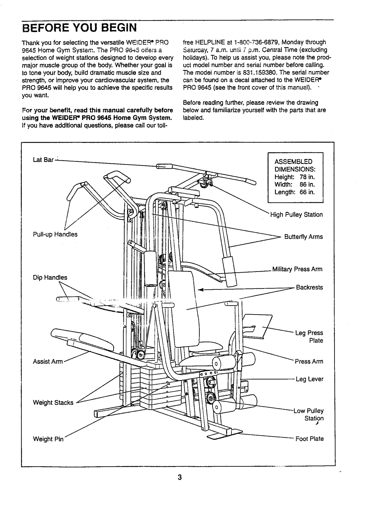
Weight Pin Foot Plate

############ ASSEMBLY
Before beginning assembly, carefully read the following information and Instructions:
THE FOLLOWING TOOLS (NOT INCLUDED) ARE REQUIRED FOR ASSEMBLY:
Assembly will be more convenient ifyou have the following tools: A socket set, a set of open-end or closed-end wrenches, or a set of ratchet wrenches.
Note: Some small parts may have been preattached for shipping. If a part is not in the parts bag, check to see if it has been pre-attached.
Locate and open the parts bag labeled "FRAME ASSEMBLY."
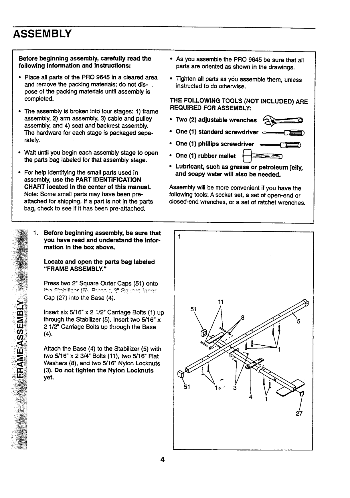
Press two 2" Square Outer Caps (51) onto
Cap (27) into the Base (4).
11
51
Insert six 5/16" x 2 1/2" Carriage Bolts (1) up through the Stabilizer (5). Insert two 5/16" x 2 1/2" Carriage Bolts up through the Base
ffl_!?
(4).
I
Attach the Base (4) to the Stabilizer (5) with two 5/16" x 2 3/4" Bolts (11), two 5/16" Flat Washers (8), and two 5/16" Nylon Locknuts (3). Do not tighten the Nylon Locknuts yet.
4
27

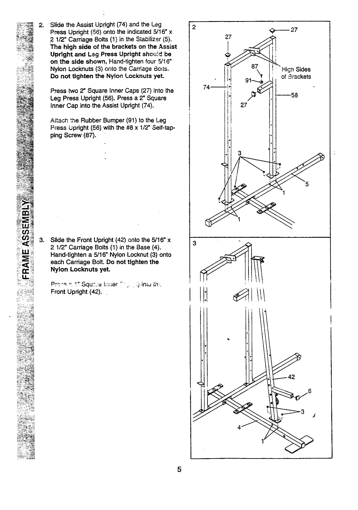
2_ Slide the Assist Upright (74) and the Leg Press Upright (56) onto the indicated 5/16" x
2
.,_--_ 27
1/2" Carriage Bolts (1) in the Stabilizer (5). The high side of the brackets on the Assist Upright and Leg Press Upright should be on the side shown. Hand-tighten four 5/16" Nylon Locknuts (3) onio the Carriage 8oils. Do not tighten the Nylon Loeknuts yet.
n Sides of _rackets
74
Press two 2" Square Inner Caps (27) into the Leg Press Upright (56). Press a 2" Square Inner Cap into the Assist Upright (74).
Afl_ch _he Rubber Bumper (91) to the Leg Press lJpdght (56) with the #8 x 1/2" Self-tapping Screw (87).
Front Upright (42).
{TfDi_
_< i<'>7 +
< •

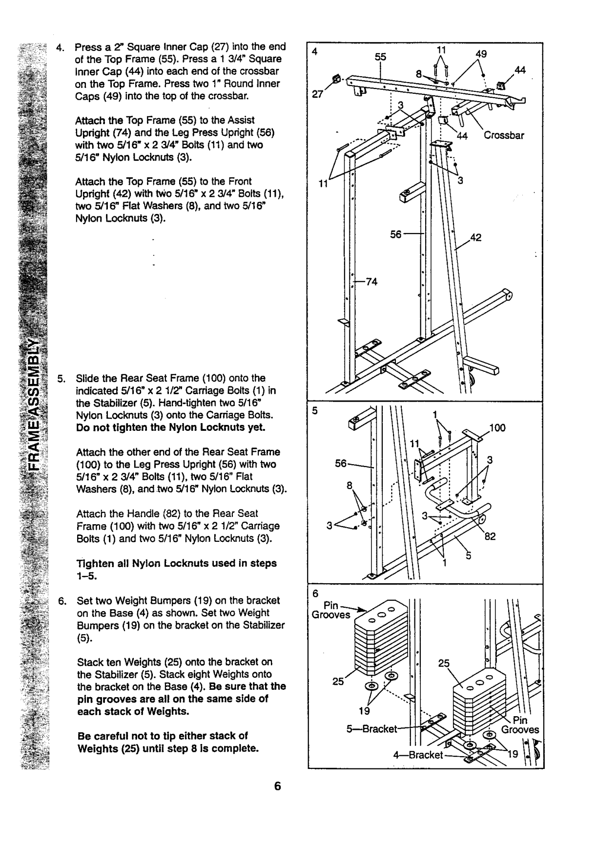
Press a 2" Square Inner Cap (27) into the end of the Top Frame (55). Press a 13/4" Square
27
55
11 49
44
Crossbar
56-----8
100
_/_23-_-_,.., ":
.
Inner Cap (44) into each end of the crossbar on the Top Frame. Press two 1" Round Inner Caps (49) into the top of the crossbar.
Attach the Top Frame (55) to the Assist Updght (74) and the Leg Press Upright (56) with two 5/16" x 2 3/4" Bolts (11) and two 5/16" Nylon Lock,nuts (3).
Attach the Top Frame (55) to the Front Updght (42) with two 5/16" x 2 3/4" Bolts (11), two 5/16" Flat Washers (8), and two 5/16" Nylon Locknuts (3).
Slide the Rear Seat Frame (100) onto the indicated 5/16" x 21/2" Carriage Bolts (1) in the Stabilizer (5). Hand-tighten two 5/16" Nylon Locknuts (3) onto the Carriage Bolts. Do not tighten the Nylon Locknuts yet.
.
Attach the other end of the Rear Seat Frame
(100) to the Leg Press Upright (56) with two 5/16" x 23/4" Bolts (11), two 5/16" Flat Washers (8), and .two 5/16" Nylon Locknuts (3).
Attach the Handle (82) to the Rear Seat Frame (100) with two 5/16" x 21/2" Carriage Botts (1) and two 5/16" Nylon Locknuts (3).
Tighten all Nylon Locknuts used in steps 1-5.
Set two Weight Bumpers (19) on the bracket on the Base (4) as shown. Set two Weight Bumpers (19) on the bracket on the Stabilizer
.
(5).
###### I 25,o"
Stack ten Weights (25) onto the bracket on the Stabilizer (5). Stack eight Weights onto the bracket on the Base (4). Be sure that the
!! 1o5---Bracket_
pin grooves are all on the same side of each stack of Weights.
Be careful not to tip either stack of Weights (25) until step 8 is complete.
4--Bracket _

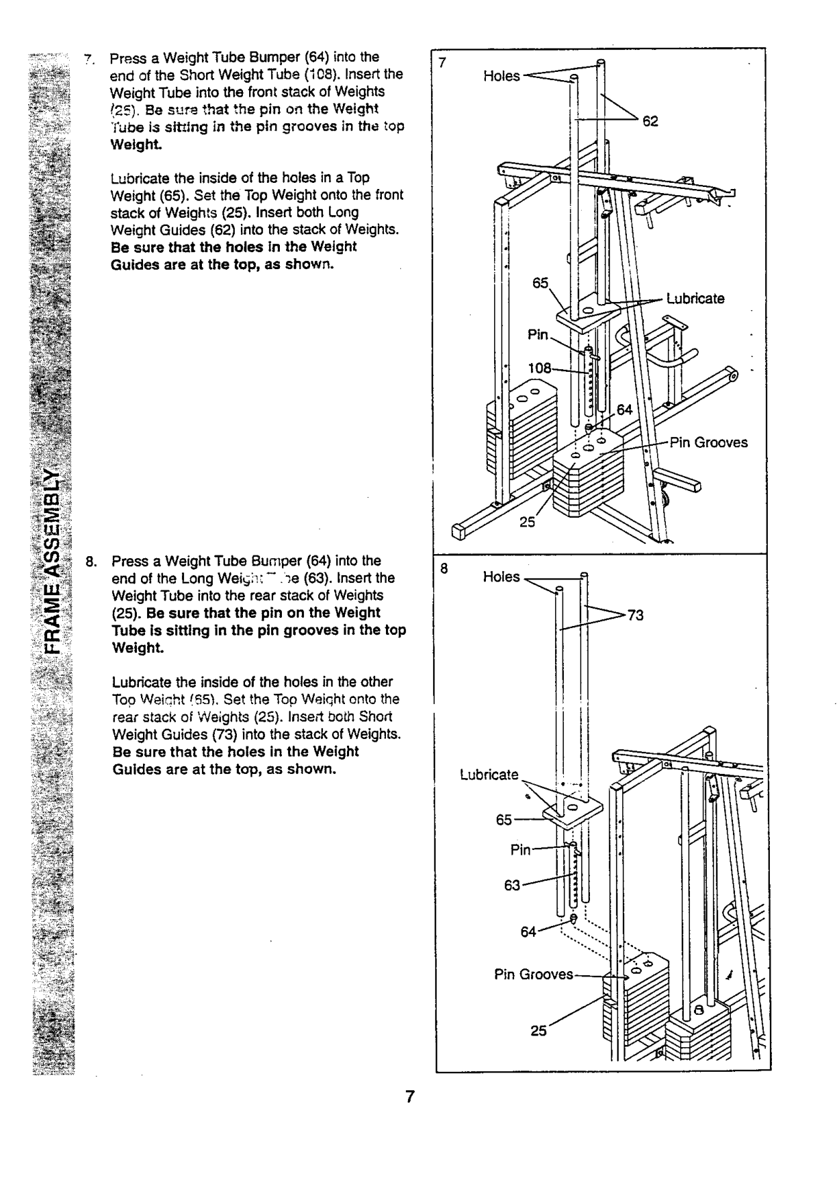
Press a Weight Tube Bumper (64) into the end of the Short Weight Tube (I08). Insertthe
Weight Tube into the front stack of Weights !25). Be sur_ that the pin on the Weight
Tube i;sslt_lng in the pin grooves in the top Weight.
Lubricate the inside of the holes in a Top Weight (65). Set the Top Weight onto the front stack of Weights (25), Insert both Long Weight Guides (62) into the stack of Weights. Be sure that the holes In the Weight Guides are at the top, as shown.
25
, Press a Weight Tube Bumper (64) into the end of the Long Wei_si_:- _e (63). Insertthe Weight Tube into the rear stack of Weights
8
Holes
(25). Be sure that the pin on the Weight Tube is sitting in the pin grooves in the top Weight.
_73
Lubricate the inside of the holes in the other Top Weight I._5"_.Set the Top Weiqht onto the rear stack of Weights (25). Insert bo_h Short Weight Guides (73) into the stack of Weights. Be sure that the holes in the Weight Guides are at the top, as shown.
!,
######## I
Lubricate

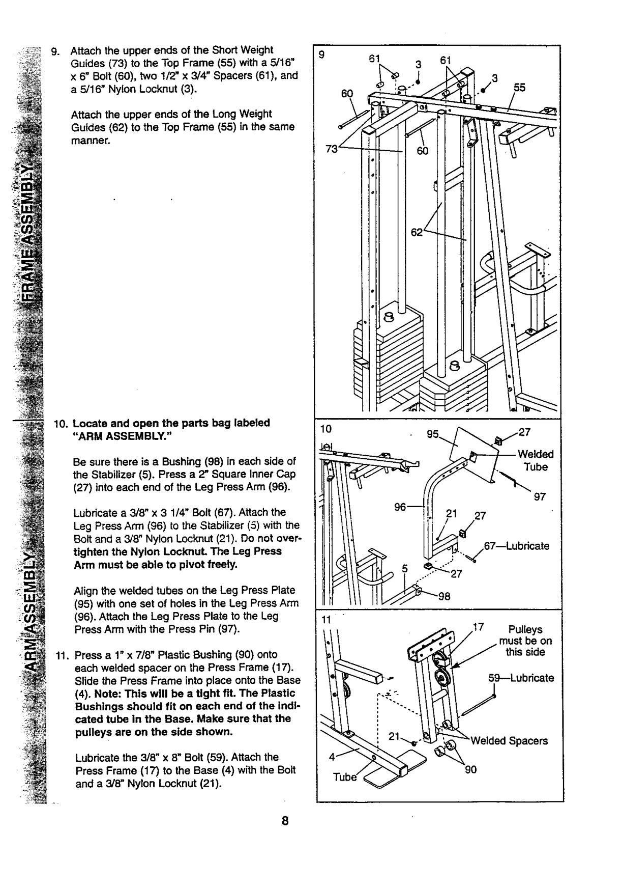
g* Attach the upper ends of the Short Weight Guides (73) to the Top Frame (55) with a 5/16" x 6" Bolt (60), two 1/2" x 3/4" Spacers (61), and a 5/16" Nylon Locknut (3).
9
61 3 61
60
Attach the upper ends of the Long Weight Guides (62) to the Top Frame (55) in the same manner.
########## < !
Be sure there is a Bushing (98) in each side of the Stabilizer (5). Press a 2" Square Inner Cap
(27) into each end of the Leg Press Arm (96).
Lubricate a 3/8" x 3 1/4" Bolt (67). Attach the Leg Press Ann (96) to the Stabilizer (5) with the Bolt and a 3/8" Nylon Locknut (21). Do not overtighten the Nylon LocknuL The Leg Press Arm must be able to pivot freely.
Align the welded tubes on the Leg Press Plate
lO
Tube
97 27
%/67--Lubricate
11
_
################## t _ 59--Lubricate
(4). Note: This will be a tight fit. The Plastic Bushings should fit on each end of the Indicated tube in the Base. Make sure that the pulleys are on the side shown.
21"_-_"_'_Welded
Lubricate the 3/8" x 8" Bolt (59). Attach the Press Frame (17) to the Base (4) with the Bolt and a 3/8" Nylon Locknut (21).
################## 90

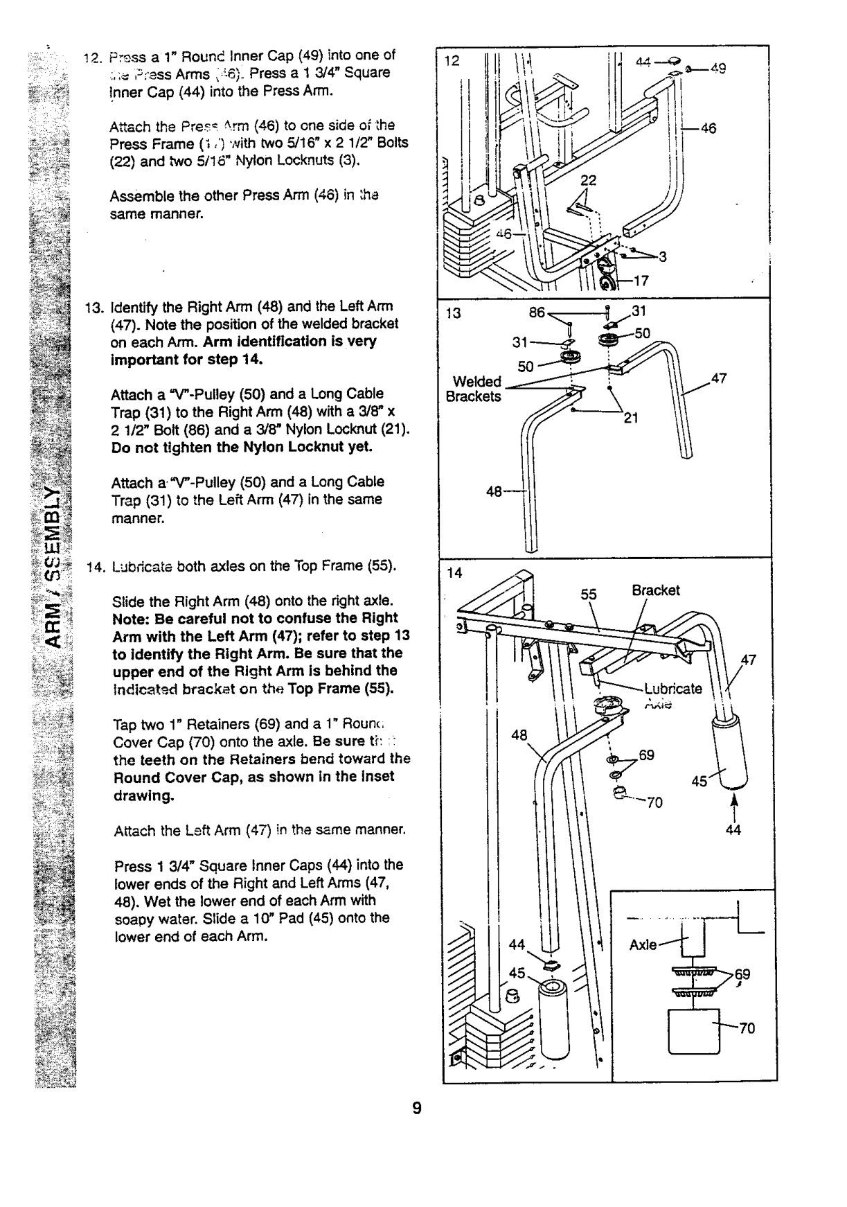
" _ !2. Press a 1" Round Inner Cap (49) into one of
....= ,_:_ss Arms, -6;. Press a 1 3/4" Square !nner Cap (44) into the Press Arm.
Attach the Pre_ _.rm (46) to one side o_the Press Frame (i ,') with two 5/16" x 2 1/2" Bolts
(22) and two 5/16" Nylon Locknuts (3).
Assemble the other Press Arm (46) in :ha same manner.
(47). Note the position of the welded bracket on each Arm. Arm identification is very important for step 14.
Attach a "V"-Pulley (50) and a Long Cable Trap (31) to the Right Arm (48) with a 3/8" x 2 1/2' Bolt (86) and a 3/8" Nylon Locknut (21). Do not tighten the Nylon Locknut yet.
Attach a."V"-Pulley (50) and a Long Cable Trap (31) to the Left Arm (47) in the same manner.
Welded /L :
48--
Slide the Right Arm (48) onto the right axle. Note: Be careful not to confuse the Right Arm with the Left Arm (47); refer to step 13 to identify the Right Arm. Be sure that the upper end of the Right Arm is behind the Indtc_t_.d bracket on the Top Frame (55).
Tap two 1" Retainers (69) and a 1" Rounc; Cover Cap (70) onto the axle. Be sure tE :the teeth on the Retainers bend toward the
48
Round Cover Cap, as shown in the inset drawing.
Attach the Left Arm (47) in the same manner.
Press 1 3/4" Square Inner Caps (44) into the lower ends of the Right and Left Arms (47, 48). Wet the lower end of each Arm with soapy water. Slide a 1(7 Pad (45) onto the lower end of each Arm.
Axle1
I"

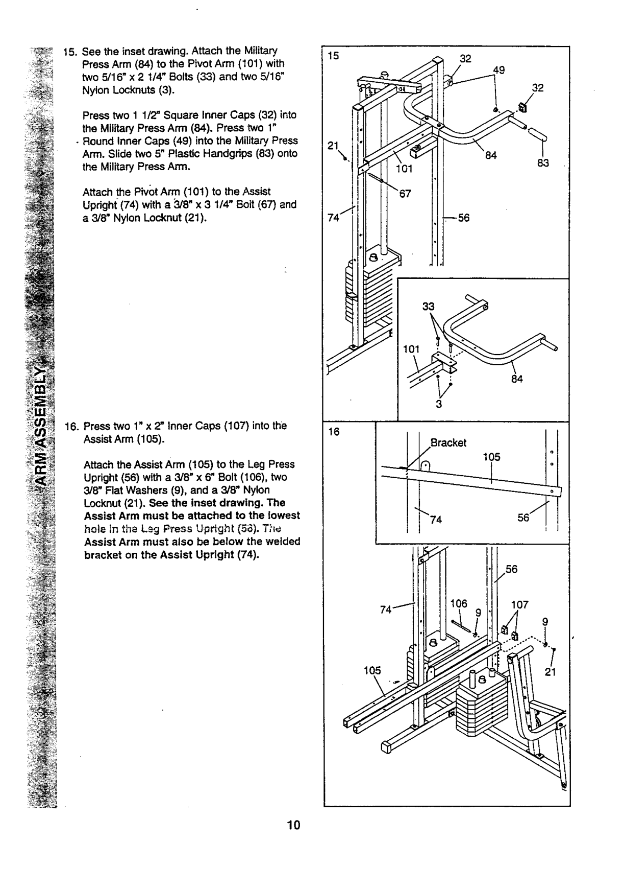
Press two 1 1/2" Square Inner Caps (32) into the Military Press Arm (84). Press two 1"
• Round Inner Caps (49) into the Military Press Arm. Slide two 5" Plastic Handgdps (83) onto the Military Press Arm.
Attach the Pivot Arm (101) to the Assist Upright (74) with a 3/8" x 3 1/4" Bott (67) and a 3/8" Nylon Locknut (21).
9
• .
_--56
Bracket /,
105
Attach the Assist Arm (105) to the Leg Press Upright (56) with a 3/8" x 6" Bolt (106), two 3/8" Flat Washers (9), and a 3/8" Nylon
Locknut (21). See the inset drawing, The Assist Arm must be attached to the lowest hole In the Ls9 P_ess Upright (5_). T?I_ Assist Arm must also be below the welded bracket on the Assist Upright (74).
""74 56"_
_"" ./56
,, lil i,000i

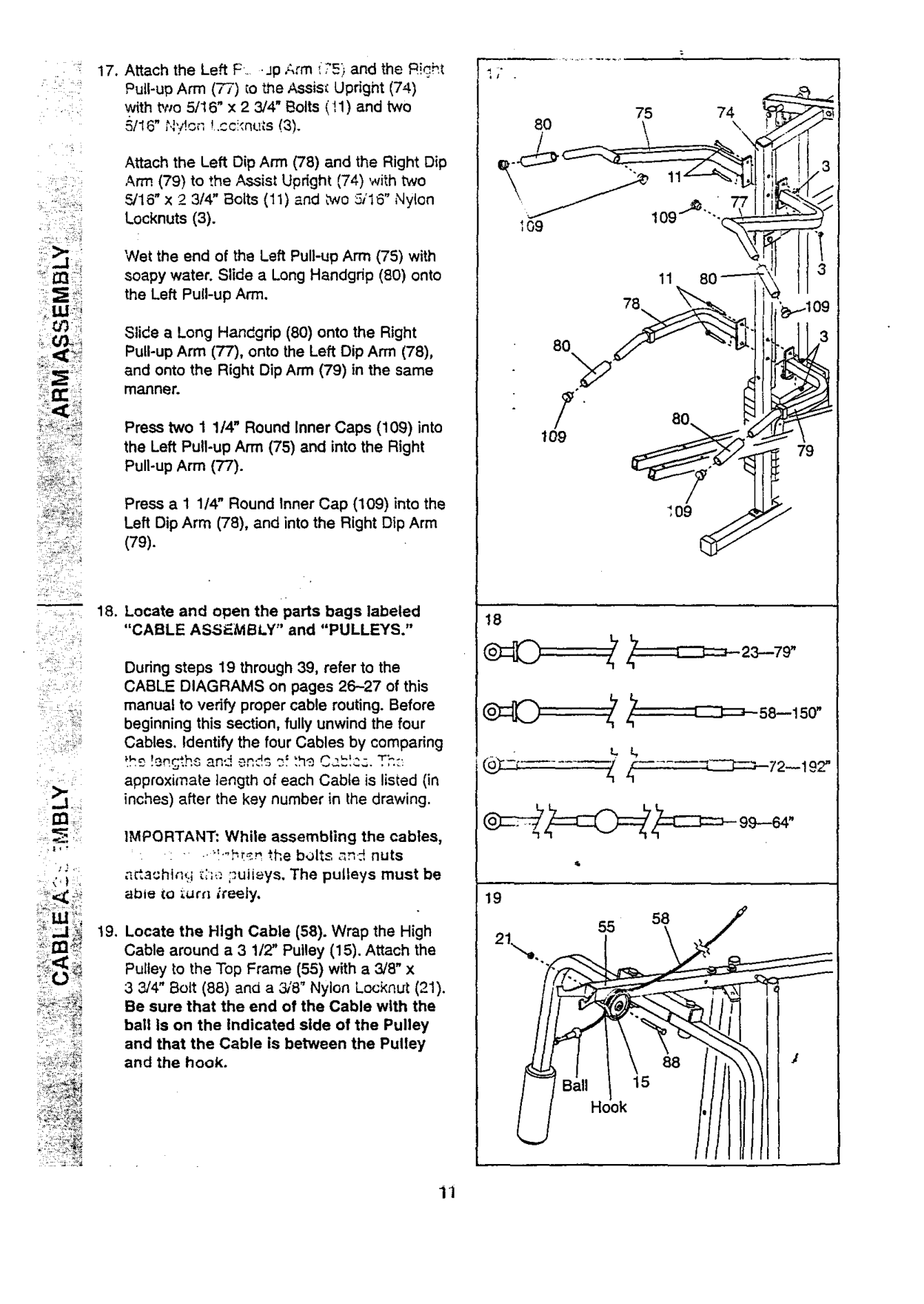
Attach the Left Dip Arm (78) and the Right Dip Arm (79) to the Assist Upright (74) with two _16"x 2 3/4" Bolts (11) and two 5116" Nylon Locknuts (3).
Wet the end of the Left Pull-up Arm (75) with soapy water. Slide a Long Handgrip (80) onto the Left Pull-up Arm.
Slide a Long Handgdp (80) onto the Right Pull-up Arm (77), onto the Left Dip Arm (78), and onto the Right Dip Arm (79) in the same manner.
Press two 1 1/4" Round Inner Caps (109) into the Left Pull-up Arm (75) and into the Right Pull-up Arm (?'7).
Press a 1 1/4" Round Inner Cap (109) into the Left Dip Arm (78), and into the Right Dip Arm
(79).
L-
################## 75 74
80 \ \
]i
ii !' _"_i _i_
18
_ _L_i _#_
• _ _ i _II_!
During steps 19 through 39, refer to the CABLE DIAGRAMS on pages 26-27 of this manual to verify proper cable routing. Before beginning this section, fully unwind the four Cables. Identify the four Cables by comparing
approximate length of each Cable is listed (in inches) after the key number in the drawing.
IMPORTANT: While assembling the cables, .... •.",-b_r, ",.hebolts _n_ nuts a_a_hl_It.i_;;_'.;_uiieys, The pulleys must be able iO i.ur_'l _i'a_iy.
,_ <
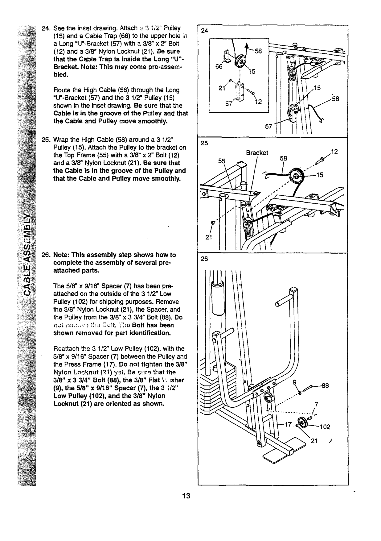
19, Locate the High Cable (58). Wrap the High Cable around a 3 1/2" Pulley (15). Attach the Pulley to the Top Frame (55) with a 3/8" x 3 3/4" Bolt (88) and a 31'8"Nylon Locknut (21). Be sure that the end of the Cable with the ball Is on the Indicated side of the Pulley and that the Cable is between the Pulley and the hook.
88
11

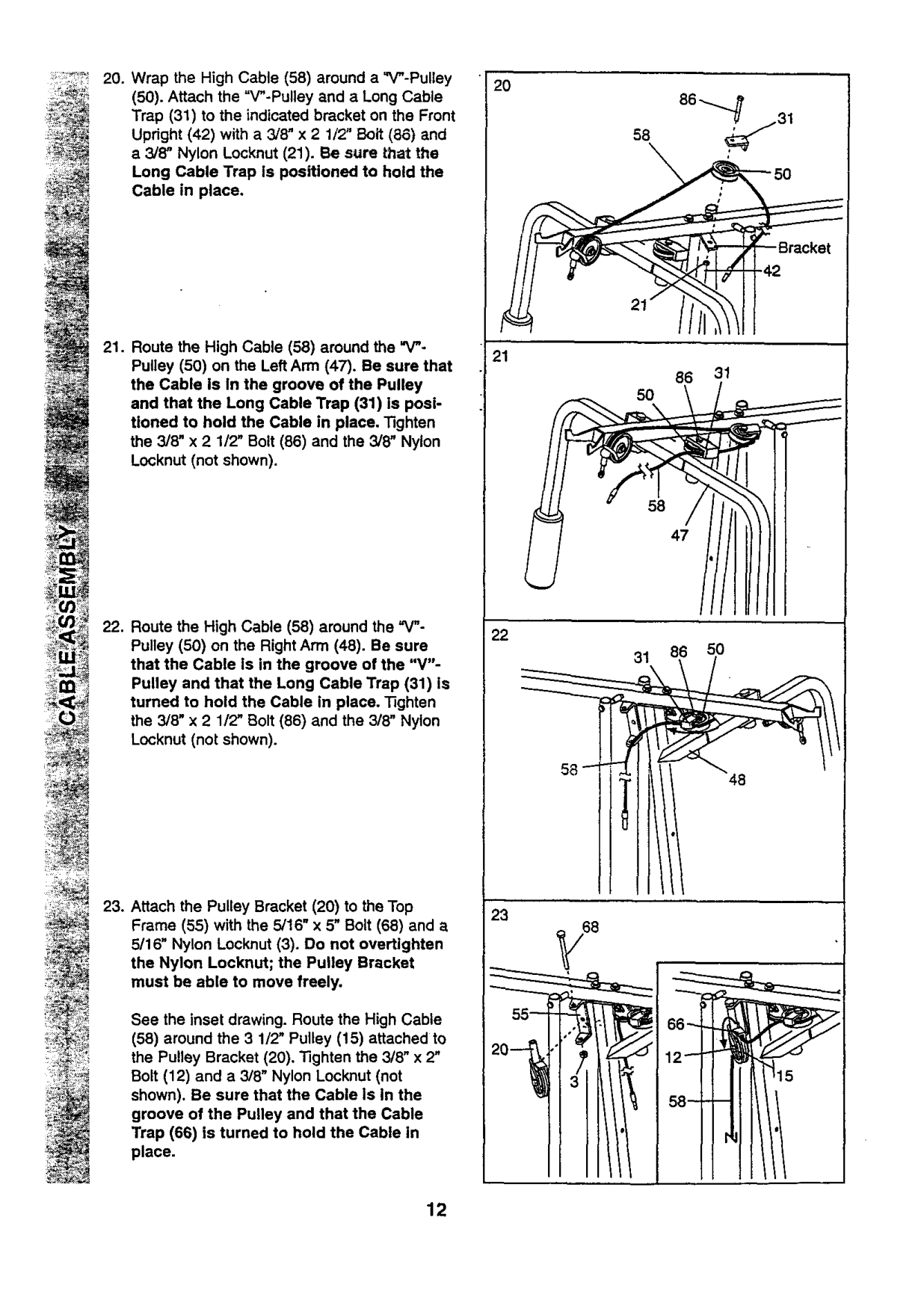
(50). Attach the "V"-Pulley and a Long Cable Trap (31) to the indicated bracket on the Front Upright (42) with a 3/8" x 2 1/2" Bolt (86) and e 3/8" Nylon Locknut (21). Be sure that the Long Cable Trap Is positioned to hold the Cable in place.
2O
31
5O
58
47
_ i_
See the inset drawing. Route the High Cable
(58) around the 3 1/2" Pulley (15) attached to the Pulley Bracket (20). Tighten the 3/8" x 2" Bolt (12) and a 3/8" Nylon Locknut (not shown). Be sure that the Cable Is In the
groove of the Pulley and that the Cable Trap (66) is turned to hold the Cable in place.
12

:_ (15) and a Cable Trap (66) to the upper hole ;n_24.Seetheinsetdrawing.Attach_-3ij2"Pulley a Long "U"-Bracket (57) with a _8" x 2" Bolt (12) and a 318" Nylon Locknut (21). Be sure that the Cable Trap is inside the Long "U"Bracket• Note: This may come pro-assembled.
Route the High Cable (58) through the Long "U"-Bracket (57) and the 3 1/2" Pulley (15) shown in the inset drawing. Be sure that the Cable is in the groove of the Pulley and that the Cable and Pulley move smoothly,
################## Bracket
58
•j12
The 5/8" x 9116" Spacer (7) has been proattached on the outside of the 3 1/2" Low Pulley (102) for shipping purposes. Remove the 3/8" Nylon Locknut (21), the Spacer, and the Pulley from the 3/8" x 3 3/4" Bolt (88). Do
?:c
################## *_ ,'_._:'..,,_._',:e ,?.,:{t•;':_o Bolt has been shown removed for pa_ identification.
Reattach _e 3 1/2' Low Pulley (102), with the 5/'8" x 9/16" Spacer (7) between the Pulley and the Press Frame (17). Do not tighten the 3/8" Nylon Locknut/q!) y_.. Be s:_r_ that the 3/8" x 3 3/4" Bolt (88), the 3/8" Flat _,',_sher
(9), the 5/8" x 9/16" Spacer (7), the 3 ;/2"
Low Pulley (102), and the 3/8" Nylon Locknut (21) are oriented as shown.

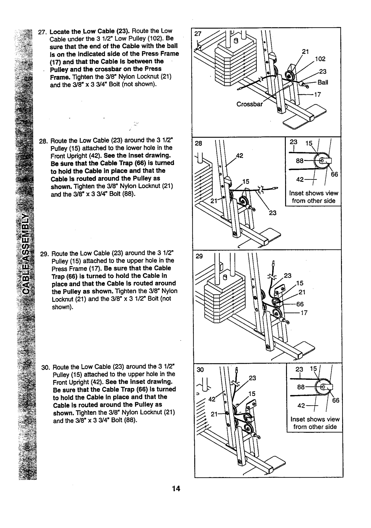
(17) and that the Cable Is between the
. Pulley and the crossbar on the Press Frame. "tighten the 3/8" Nylon Locknut (21) and the 3/8" x 3 3/4" Bolt (not shown).
Pulley (15) attached to the lower hole in the Front Upright (42). See the Inset drawing. Be sure that the Cable Trap (66) is turned to hold the Cable In place and that the Cable Is routed around the Pulley as shown, "Rghten the 3/8" Nylon Locknut (21) and the 3/8" x 3 3/4" Bolt (88).
17102
23_Ball
--17
##### <
88--
6 42--
Inset shows view from other side
23
23
--66 --17
ii
J
6
Inset shows view from other side
J

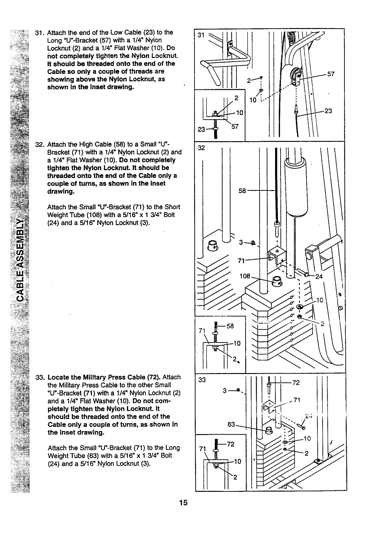
Cable so only a couple of threads are showing above the Nylon Locknut, as shown In the Inset drawing.
Attach the Small =U"-Bracket (71) to the Short Weight Tube (108) with a 5/16" x 1 3/4" Bolt
(24) and a 5/16" Nylon Locknut (3).
Attach the Small "U"-Bracket (71) to the Long Weight Tube (63) with a 5/16" x 1 3/4" Bolt
(24) and a 5/16" Nylon Locknut (3).

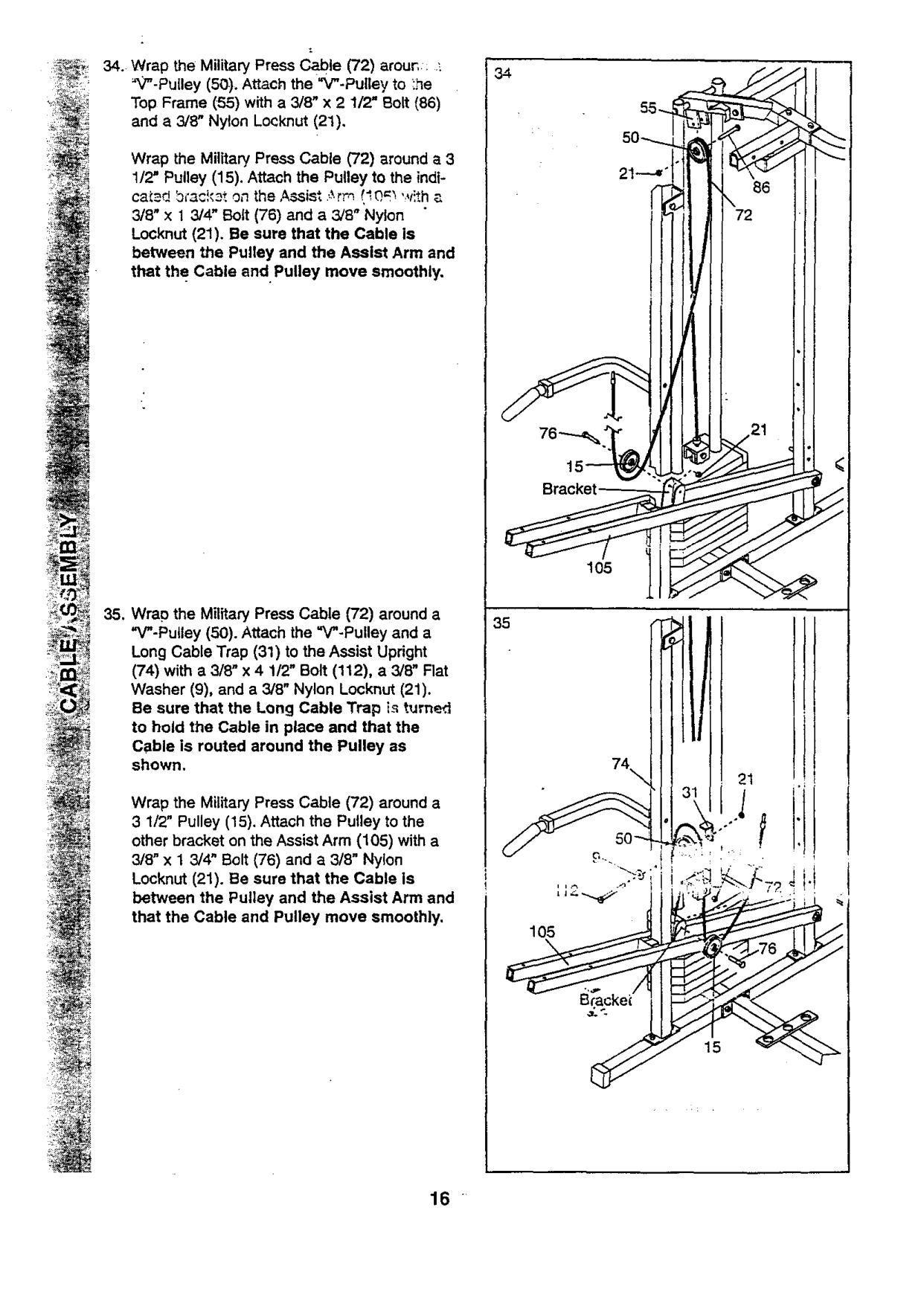
Wrap the Military Press Cable (72) around a 3 1/2" Pulley (15). Attach the Pulley to the indtcatad bmckat on the Assist .,_rm !'.0,m 'v!th a 3/8" x 1 3/4" Bolt (76) and a 3/8" Nylon Locknut (21). Be sure that the Cable is between the Pulley and the Assist Arm and that the Cable and. Pulley move smoothly.
Bracket
105
(74) with a 3/8" x 4 112" Bolt (112), a 3/8" Flat Washer (9), and a 3/8" Nylon Locknut (21). Be sure that the Long Cable Trap is turned to hold the Cable in place and that the Cable is routed around the Pulley as shown,
21
Wrap the Military Press Cable (72) around a 3 1/2" Pulley (15). Attach the Pulley to the other bracket on the Assist Arm (105) with a 3/8" x 1 3/4" Bolt (76) and a 3/8" Nylon
Locknut (21). Be sure that the Cable Is between the Pulley and the Assist Arm and that the Cable and Pulley move smoothly.
105
16

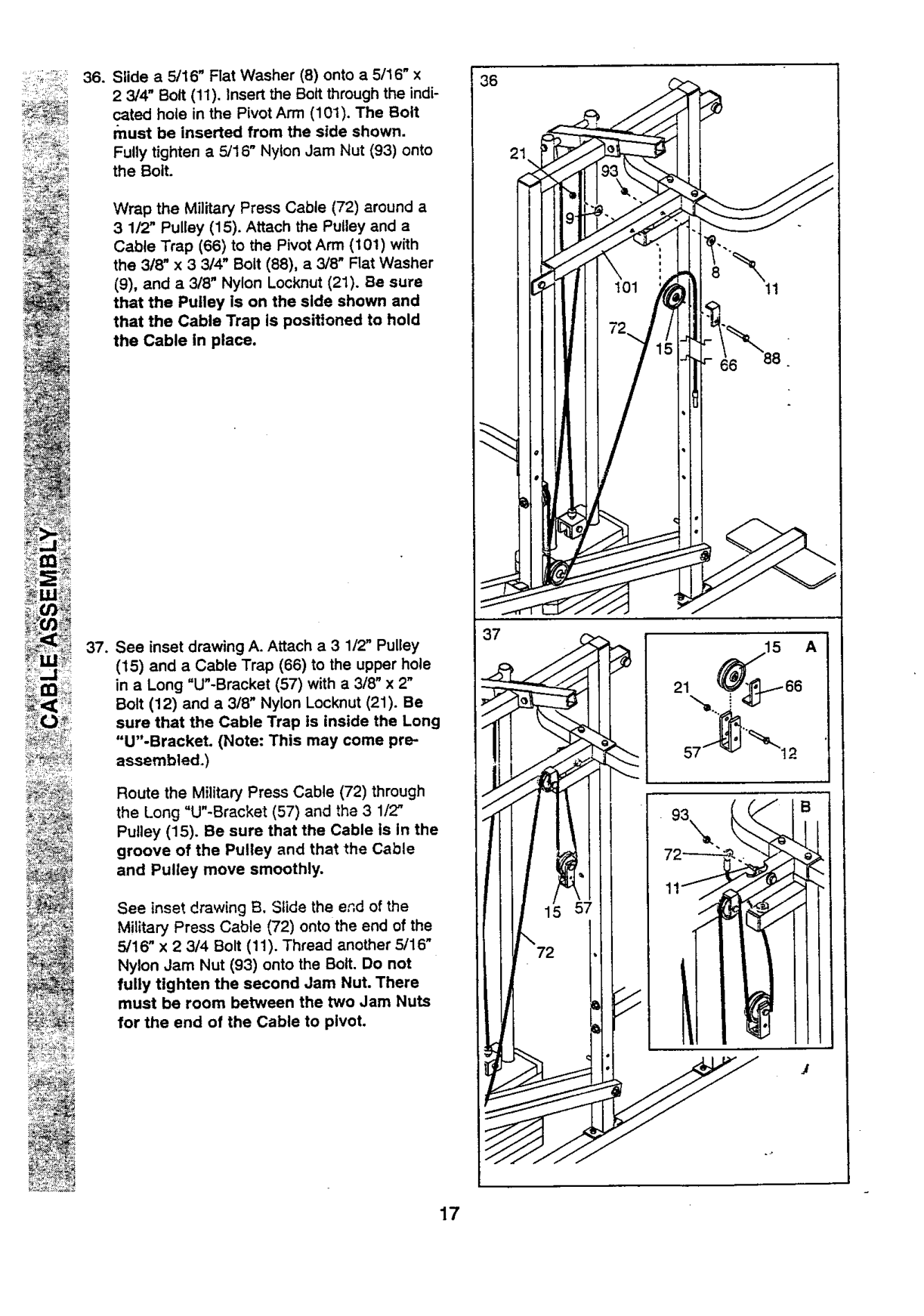
################## 36. Slide a 5/16" Flat Washer (8) onto a 5116" x
36
Wrap the Military Press Cable (72) around a
(9), and a 3/8" Nylon Locknut (21). Be sure that the Pulley is on the side shown and that the Cable Trap is positioned to hold the Cable in place.
37
################### 37. See inset drawing A. Attach a 3 1/2" Pulley
(15) and a Cable Trap (66) to the upper hole in a Long "U"-Bracket (57) with a 318" x 2"
Bolt (12) and a 3/8" Nylon Locknut (21). Be sure that the Cable Trap is inside the Long "U"-Bracket. (Note: This may come preassembled.)
Route the Military Press Cable (72) through the Long "U"-Bracket (57) and the 3 1/2" Pulley (15). Be sure that the Cable Is In the groove of the Pulley and that the Cable and Pulley move smoothly.
########### 93\
See inset drawing B, Slide the end of the Military Press Cable (72) onto the end of the 5/16" x 2 3/4 Bolt (11). Thread another 5/16" Nylon Jam Nut (93) onto the Bolt. Do not fully tighten the second Jam Nut. There must be room between the two Jam Nuts for the end of the Cable to pivot.
\
72

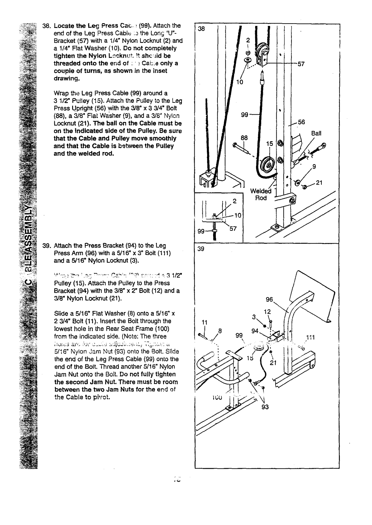
Wrap the Leg Press Cable (99) around a 3 1/2" Pu!tey (15). Attach the Pulley to the Leg Press Updght (56) with the 3/8" x 3 3/4" Bolt
(88), a 3/8" FIaLWasher (9), and a 3/8" Nylon Locknut (21). The ball on the Cable must be on the Indicated side of the Pulley. Be sure that the Cable and Pulley move smoothly and that the Cable is between the Pulley and the welded rod.
€
Bail
Rod
99_ 57
39
!;_":_,}',:b" ' ._,,':_'" '"" C,2_':': "_':_ t:':: :d _-3 1/2" Pulley (15). Attach the Pulley to the Press Bracket (94) with the 3/8" x 2" Bolt (12) and a 3/6" Nylon Locknut (21).
96 12
Slide a 5/16" Flat Washer (8) onto a 5/16" x 2 3/4" Bolt (11). Insert the Bolt through the lowest hole in the Rear Seat Frame (100) from the indicated side. (Note: The three
5/16" Nyion Jam Nut (93) onto the Bolt. Slide the end of the Leg Press Cable (99) onto the end of the Bolt. Thread another 5/16" Nylon Jam Nut onto the Bolt. Do not fully tighten the second Jam Nut. There must be room between the two Jam Nuts for the end of the Cable to pivot.
93

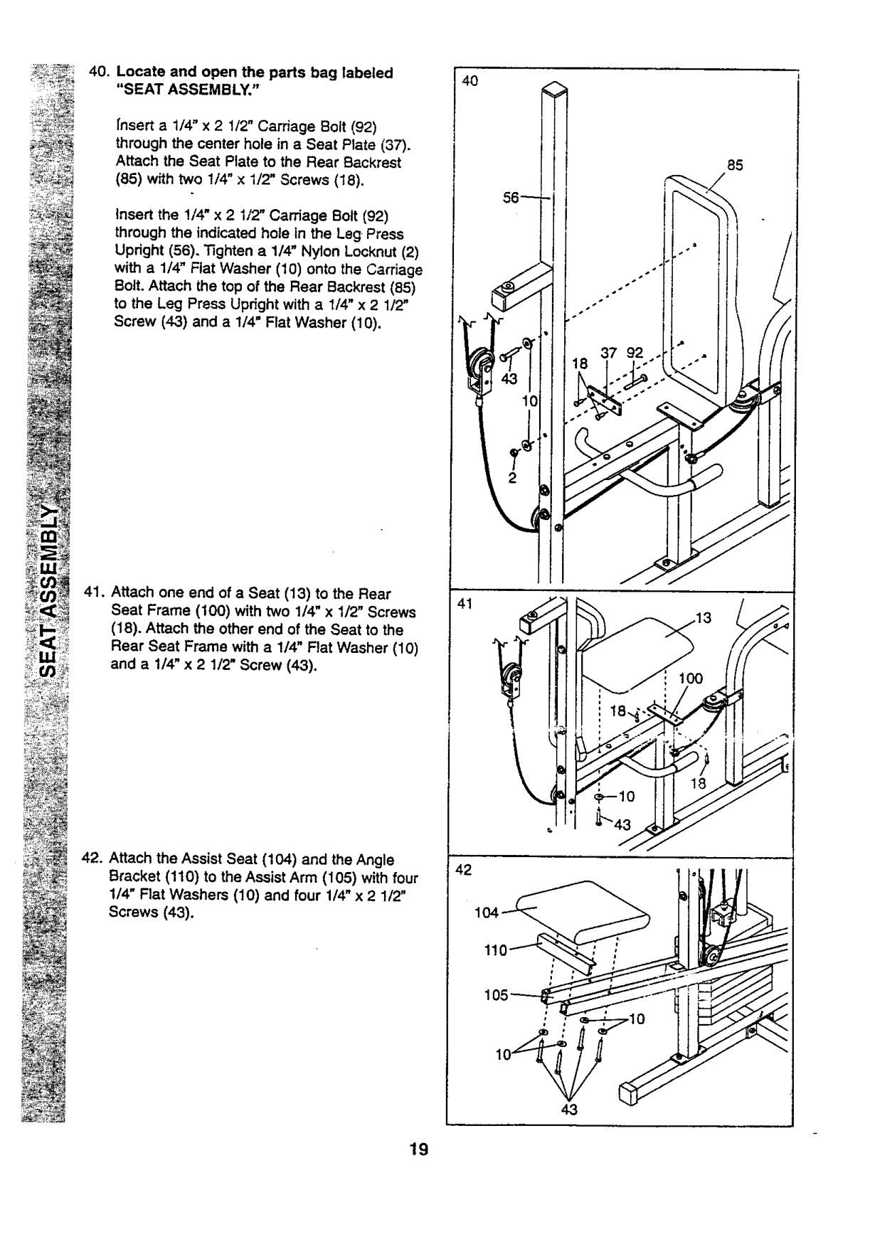
################## 40. Locate and open the parts bag labeled"SEAT ASSEMBLY,"
85
37 92
fnsert a 1/4" x 2 1/2" Carriage Bolt (92) through the center hole in a Seat Plate (37). Attach the Seat Plate to the Rear Backrest
(85) with two 1/4" x I/2" Screws (18).
Insert the !/4" x 2 1/2" Carriage Bolt (92) through the indicated hole in the Leg Press Upright (56). Tighten a 1/4" Nylon Locknut (2) with a 1/4" Flat Washer (10) onto the Carriage Bolt. Attach the top of the Rear Backrest (85) to the Leg Press Updght with a 1/4" x 2 1/2" Screw (43) and a 1/4" Flat Washer (10).
################### 41. Attach one end of a Seat (13) to the RearSeat Frame (100) with two 1/4" x 1/2" Screws
(18). Attach the other end of the Seat to the Rear Seat Frame with a 1/4" Flat Washer (10) and a 1/4" x 2 1/2" Screw (43).
################### 42. Attach the Assist Seat (104) and the AngleBracket (110) to the Assist Arm (105) with four1/4" Flat Washers (10) and four 1/4" x 2 1/2"Screws (43).
11
4.3
19

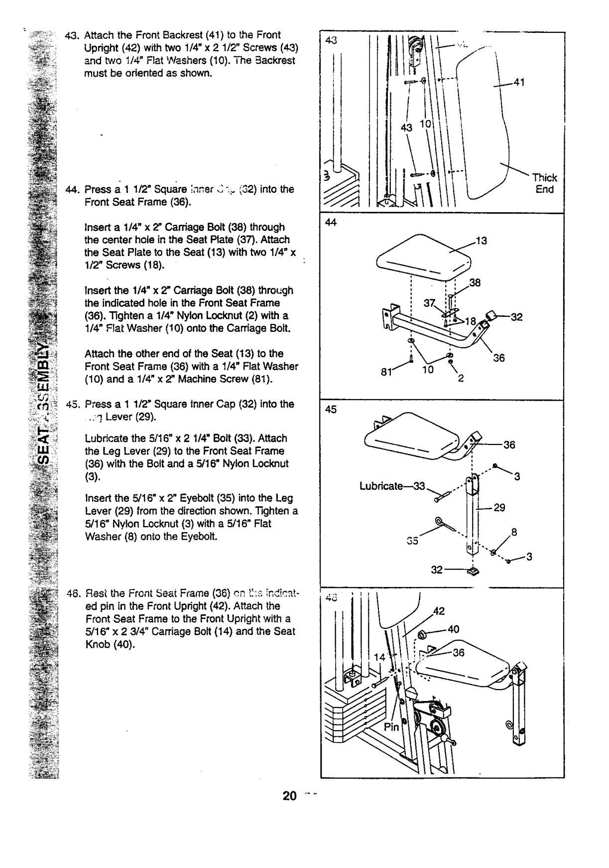
Press a 1 1/2" Square ' " "- "^=n,,er,___,_2)into the Front Seat Frame (36).
Insert a 1/4" x 2" Carriage Bolt (38) through the center hole in the Seat Plate (37). Attach the Seat Plate to the Seat (13) with two 1/4" x 1/2" Screws (18).
Insert the 1/4" x 2" Carriage Bolt (38) thro_:gh the indicated hole in the Front Seat Frame
(36). "Nghten a 1/4" Nylon Locknut (2) with a 1/4" Flat Washer (!0) ontothe Carriage Bolt.
Attach the other end of the Seat (13) to the Front Seat Frame (36) with a 1/4" Flat Washer
(10) and a 1/4" x 2" Machine Screw (81).
Press a 1 1/2" Square inner Cap (32) into the
•,_] Lever (29).
Lubricate the 5/16" x 2 1/4" Bolt (33). Attach the Leg Lever (29) to the Front Seat Frame (36) with the Bolt and a 5/16" Nylon Locknut
(3). Insert the 5/16" x 2" Eyebolt (35) into the Leg
Lever (29) from the direction shown. Tighten a 5/16" Nylon Locknut (3) with a 5/16" Flat Washer (8) onto the Eyeboit.
4.3
f -
f
4
################## End
36 10
2
_36
################## Lubdcate--33,_.,-!
=s__
i_
i_i_ ,?_
0

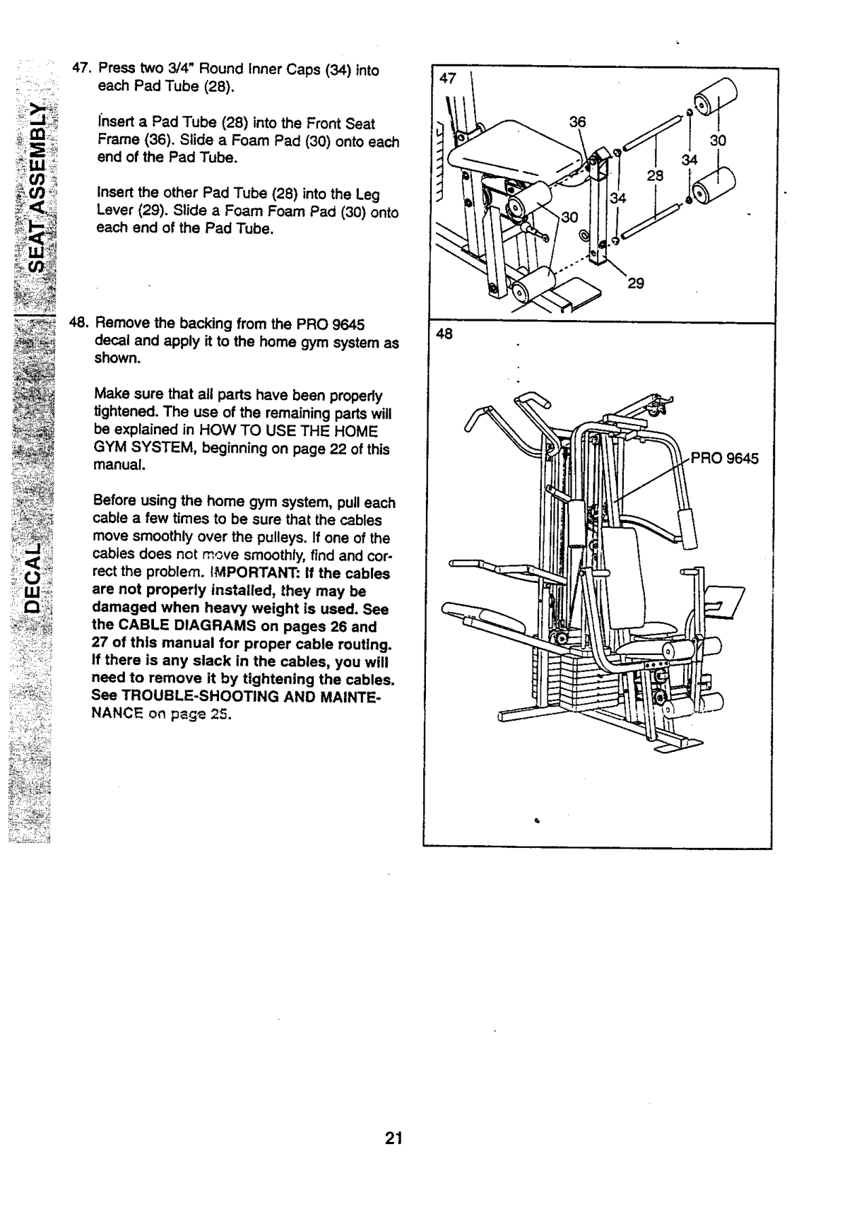
Insert a Pad Tube (28) into the Front Seat Frame (36). Slide a Foam Pad (30) onto each end of the Pad Tube.
Insert the other Pad Tube (28) into the Leg Lever (29). Slide a Foam Foam Pad (30) onto each end of the Pad Tube.
m
48, Remove the backing from the PRO 9645 decal and apply it to the home gym system as shown.
48
Make sure that all parts have been propedy tightened. The use of the remaining parts will be explained in HOW TO USE THE HOME GYM SYSTEM, beginning on page 22 of this manual.
.PRO 9645
Before using the home gym system, pull each cable a few times to be sure that the cables move smoothly over the pulleys. If one of the cables does not move smoothly, find and correct the problem. IMPORTANT: If the cables are not properly installed, they may be damaged when heavy weight is used. See the CABLE DIAGRAMS on pages 26 and 27 of this manual for proper cable routing. If there is any slack in the cables, you will need to remove it by tightening the cables. See TROUBLE-SHOOTiNG AND MAINTENANCE on p_ge 25.

############ HOW TO USE THE HOME GYM SYSTEM
The instructions below describe how each part of the home gym system can be adiusted. Refer _othe .=,xer3ise poster accompanying this manual to see how the home gym system shoutd be set up for each exercise. IMPORTANT: When attaching the lat bar or nylon strap, make sure that the attachments are in the correct starting position for the exercise to be performed. If there is any slack In the cables or chain as an exercise is performed, tP,0 effectivenes.s of the exercise will be reduced.
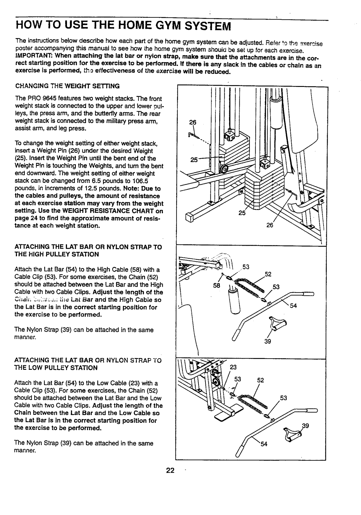
CHANGING THE WEIGHT SETTING The PRO 9645 features two weight stacks. The front weight stack is connected to the upper and lower pulleys, the press arm, and the butterfly arms. The rear weight stack isconnected to the military press arm, assist arm, and leg press. To change the weight setting of either weight stack, insert a Weight Pin (26) under the desired Weight
26
(25). Insert the Weight Pin until the bent end of the Weight Pin is touching the Weights, and turn the bent end downward. The weight setting of either weight stack can be changed from 6.5 pounds to 106.5 pounds, in increments of 12.5 pounds. Note: Due to the cables and pulleys, the amount of resistance at each exercise station may vary from the weight settlng. Use the WEIGHT RESISTANCE CHART on page 24 to find the approximate amount of resistance at each weight station.
25
26
AT-rACHING THE LAT BAR OR NYLON STRAP TO THE HIGH PULLEY STATION
Attach the Let Bar (54) to the High Cable (58) with a Cable Clip (53). For some exercises, the Chain (52)
should be attached between the Lat Bar and the High Cable with two Cable Clips. Adjust the length of the C;-_,ti_,L.._,_'_._,;;.he Lat _lar and the High Cable so the Lat Bar is in the correct starting position for the exercise to be performed.
The Nylon Strap (39) can be attached in the same manner.
39
ATTACHING THE LAT BAR OR NYLON STRAP TO THE LOW PULLEY STATION
################## 23 53 52
Attach the Lat Bar (54) to the Low Cable (23) with a Cable Clip (53). For some exercises, the Chain (52) should be attached between the Lat Bar and the Low Cable with two Cable Clips. Adjust the length of the Chain between the Lat Bar and the Low Cable so
53
the Lat Bar Is in the correct starting position for the exercise to be performed.
The Nylon Strap (39) can be attached in the same manner.

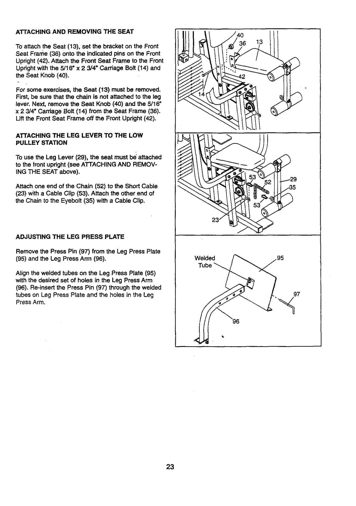
################## AI-I'ACHING AND REMOVING THE SEAT
To attach the Seat (13), set the bracket on the Front Seat Frame (36) onto the indicated pins on the Front Upright (42), Attach the Front Seat Frame to the Front Upright with the 5/16" x 2 3/4' Carriage Bolt (14) and the Seat Knob (40).
For some exercises, the Seat (13) must be removed. First, be sure that the chain is not attached to the leg lever. Next, remove the Seat Knob (40) and the 5/16" x 2 3/4" Carriage Bolt (14) from the Seat Frame (36). Lift the Front Seat Frame off the Front Upright (42).
ATTACHING THE LEG LEVER TO THE LOW PULLEY STATION
To use the Leg Lever (29), the seat must be attached to the front upright (see ATTACHING AND REMOVING THE SEAT above).
52 129
Attach one end of the Chain (52) to the Short Cable
(23) with a Cable Clip (53). Attach the other end of the Chain to the Eyebolt (35) with a Cable Clip.
ADJUSTING THE LEG PRESS PLATE
Remove the Press Pin (97) from the Leg Press Plate
Welded Tube
Align the welded tubes on the Leg Press Plate (95) with the desired set of holes in the Leg Press Arm
97
96
############## 23

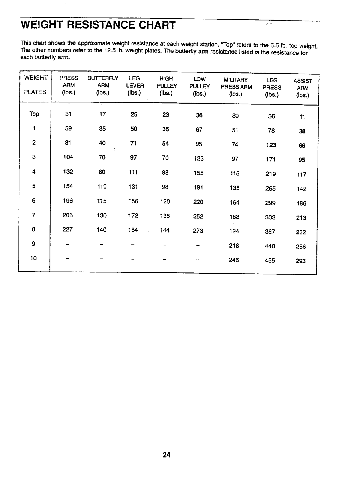
############ WEIGHT RESISTANCE CHART
chart shows the approximate weight resistance at each weight station. "Top" refers to the 5.5 lb. too weight. other numbers refer to the 12.5 Ib, weight plates. The butterfly ann resistance listed is the resistance for
butterfly arm.
WEIGHT
############# i PRESS BUTTERFLY MILITARY ASSIST ARM LEVER PULLEY PULLEY PRESSARM PRESS ARM (Ibs.) Obs.) (Ibe.) (Ibs.) (Ibs.) (Ibs.) (lbs.) (Ibs.)
PLATES
Top
1
144

############ TROUBLE-SHOOTING AND MAINTENANCE
Inspect and tighten all parts each time you use the home gym system. Replace any worn parts immediately• The home gym system can be cleaned using a damp cloth and mild non÷abrasive detergent. Do not use solvents,
TIGHTENING THE CABLES
Woven cable, the type of cable used on the home gym system, can stretch slightlywhen it is first used. If there
is slack in the cables before resistance is felt, the cables should be tightened, If any slack is felt when using the front weight stack, both the High Cable (58) and the Low Cable (23) will need to be tightened. If any slack is felt when using the rear weight stack, both the Military Press Cable (72) and the Leg Press Cable (99) will need to
be tightened,
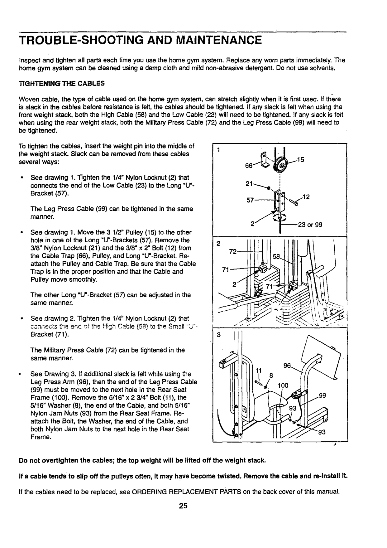
To tighten the cables, insert the weight pin intothe middle of the weight stack. Slack can be removed from these cables several ways:
The Leg Press Cable (99) can be tightened in the same manner.
See drawing 1. Move the 3 1/2" Pulley (15) to,the other hole in one of the Long =U"-Brackets (57). Remove the 3/8" Nylon Locknut (21) and the 3/8" x 2" Bolt (12) from the Cable Trap (66), Pulley, and Long "U"-Bracket. Reattach the Pulley and Cable Trap. Be sure that the Cable Trap is in the proper position and that the Cable and Pulley move smoothly.
The other Long "U"-Bracket (57) can be adjusted in the same manner.
3
Bracket (71).
The Military Press Cable (72) can be tightened in the same manner.
See Drawing 3. If additional slack is felt while using the Leg Press Arm (96), then the end of the Leg Press Cable
(99) must be moved to the next hole in the Rear Seat Frame (100). Remove the 5/16" x 2 3/4" Bolt (11), the 5/16" Washer (8), the end of the Cable, and both 5/16"
/99
Nylon Jam Nuts (93) from the Rear Seat Frame. Reattach the Bolt, the Washer, the end of the Cable, and both Nylon Jam Nuts to the next hole in the Rear Seat Frame.
\
\
Do not overtighten the cables; the top weight will be lifted off the weight stack.
If a cable tends to slip off the pulleys often, it may have become twisted. Remove the cable and re-install it.
If the cables need to be replaced, see ORDERING REPLACEMENT PARTS on the back cover of this manual.

############ CABLE DIAGRAMS
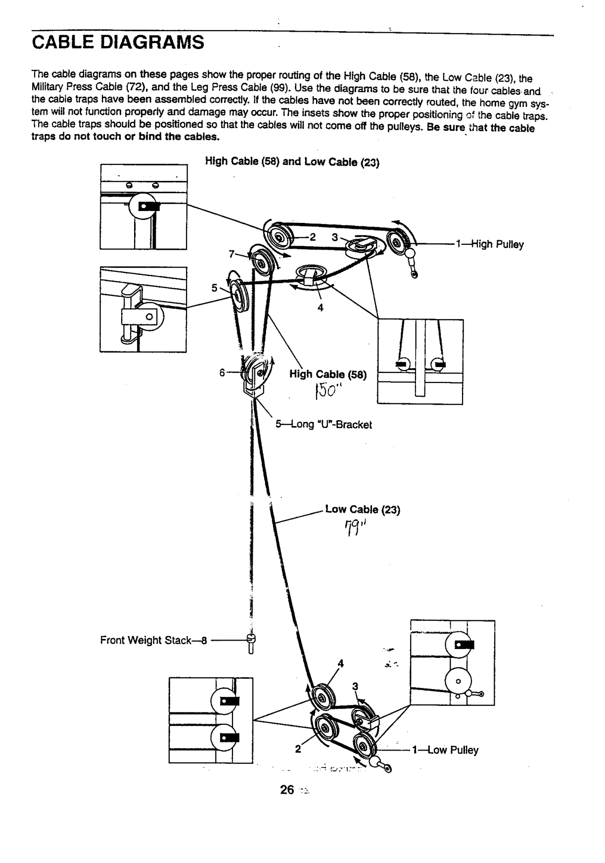
The cable diagrams on these pages show the proper routing of the High Cable (58), the Low Cable (23), the Military Press Cable (72), and the Leg Press Cable (99). Use the diagrams to be sure that the four cablesand the cable traps have been assembled correctly. correctly
damage may occur. The insets show the proper should be positioned so that the cables will not come off the
touch or bind the cables.
High
!1
Cable (58)
\
Stack---8
4
3

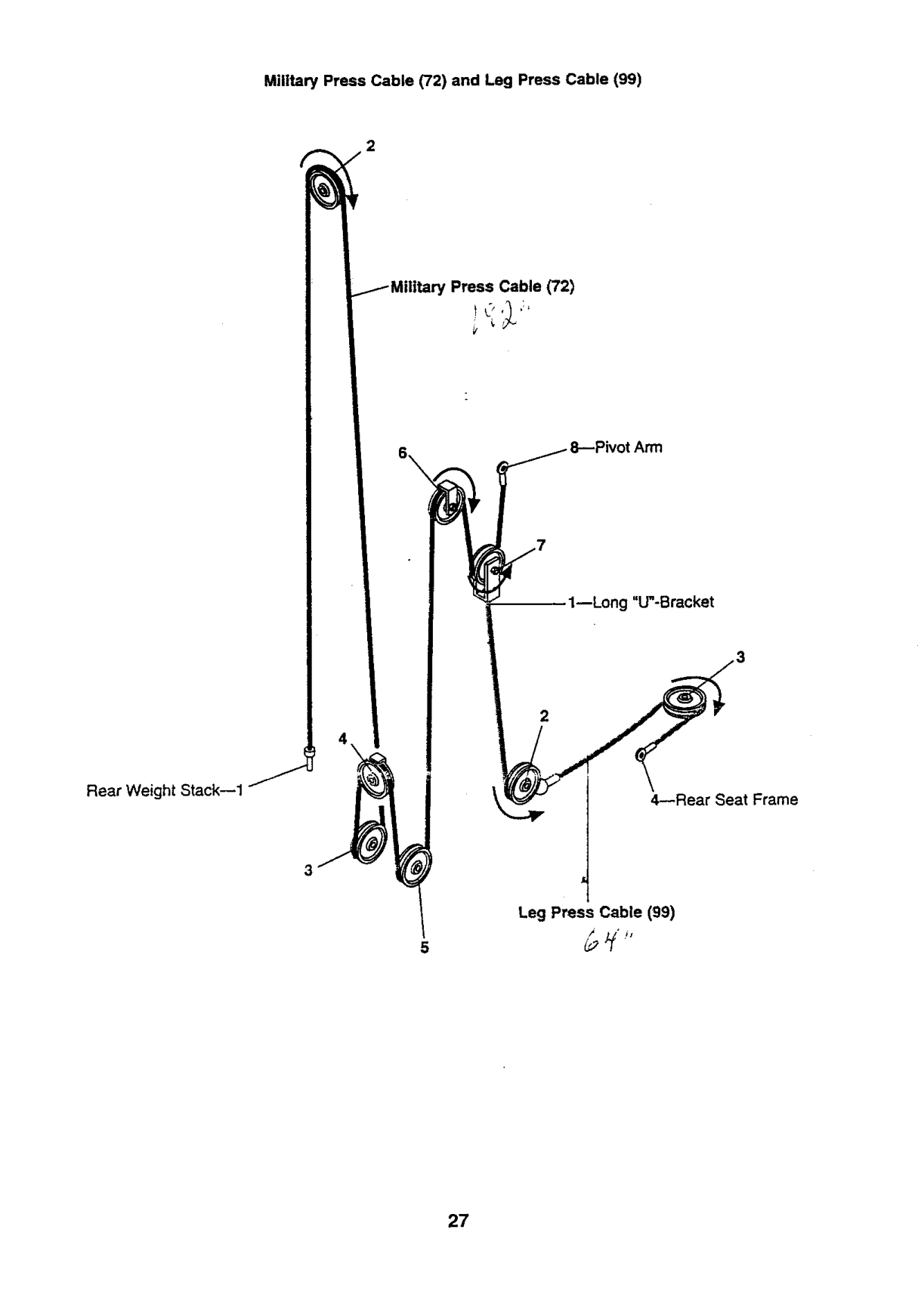
Military Press Cable (72) and Leg Press Cable (99)
Cable (72)
,tArm
1--Long "U"-Bracket
################## 2
Rear Weight Stack--1
4--Rear Seat Frame
################## Leg Press Cable (99)
/4 i$
5

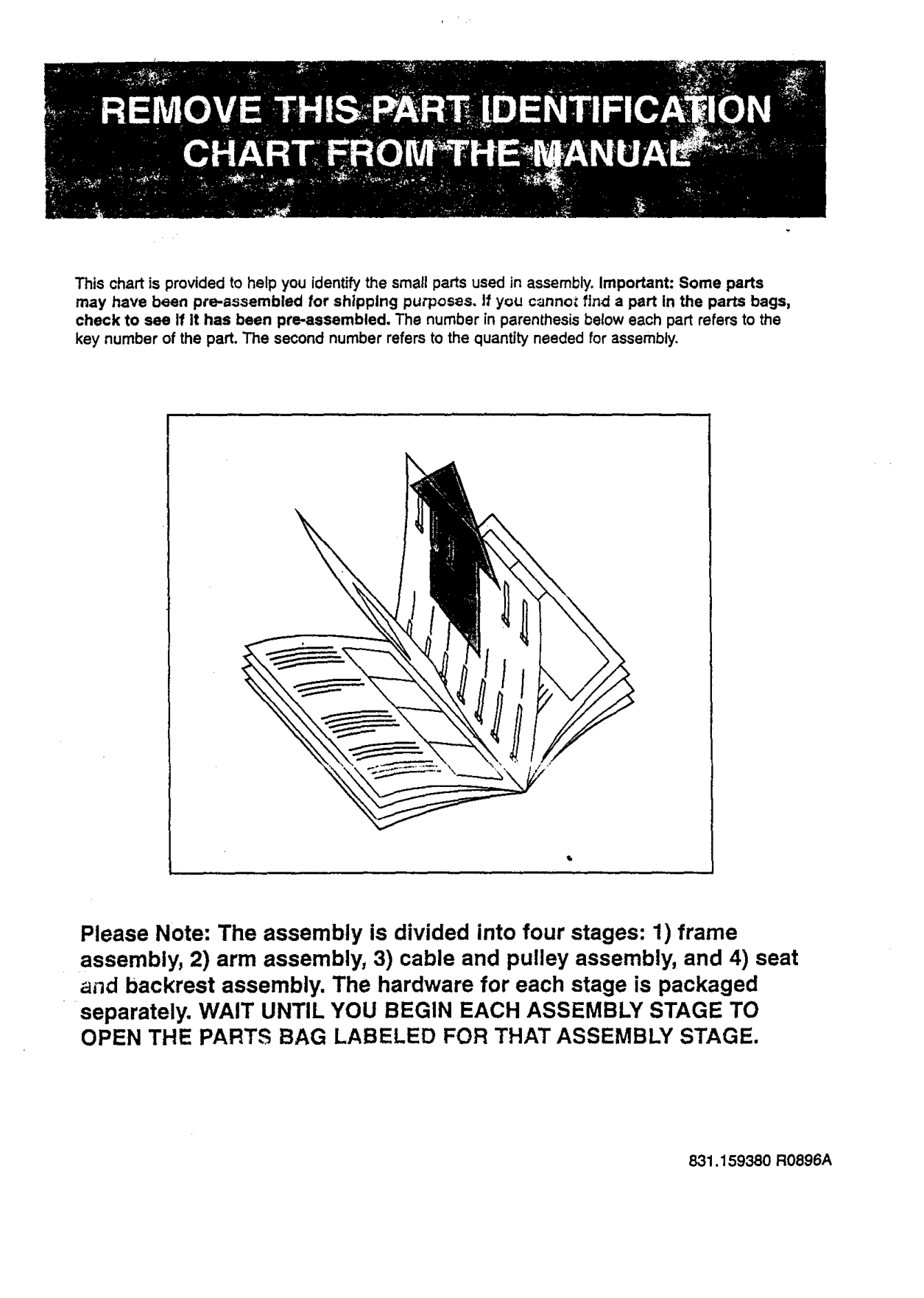
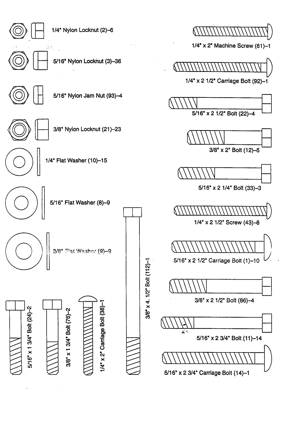
This chart is provided to help you identify the small parts used in assembly. Important: Some parts may have been pre-aeeembled for shipping purposes. If you cannc_ find a part In the parts bags, check to see If It has been pre-aesembled. The number in parenthesis below each part refers to the key number of the part. The second number refers to the quantity needed for assembly.
Please Note: The assembly is divided into four stages: 1) frame assembly, 2) arm assembly, 3) cable and pulley assembly, and 4) seat and backrest assembly. The hardware for each stage is packaged
separately. WAIT UNTIL YOU BEGIN EACH ASSEMBLY STAGE TO OPEN THE PARTS BAG LABELED FOR THAT ASSEMBLY STAGE.
831.159380 R0896A

_ 1/4" Nylon Locknut (2)-6
1/4" x 2" Machine Screw (81)-1
@_ 5/16" Nylon Locknut (3)--36
########## _\\\\\\\\\\\\\\\\\\\\\W4
1/4" x 2 1/2" Carriage Bolt (92)-1
5/16" Nyton Jam Nut (93)-4
5/16" x 2 1/2" Bolt (22)--4
3/8" Nylon Locknut (21)-23
3/8" x 2" Bolt (12)-5
1/4" Flat Washer (10)-15
5/16" x 2 1/4" Bolt (33)-3
5/16" Flat Washer (8)-9
1/4"x 2 1/2" Screw (43)--8
3/8" F!'_,t W._.sh£r (9)-9
0 rn
3/8" x 2 1/2" Bolt (86)-4
#### E\\\\_,\I
5/16" x2 3/4" Bolt (11)-14
#### E\\\\\\\\&\\\\\\\\\ I
5/16" x 2 3/4" Cardage Bolt (14)-1

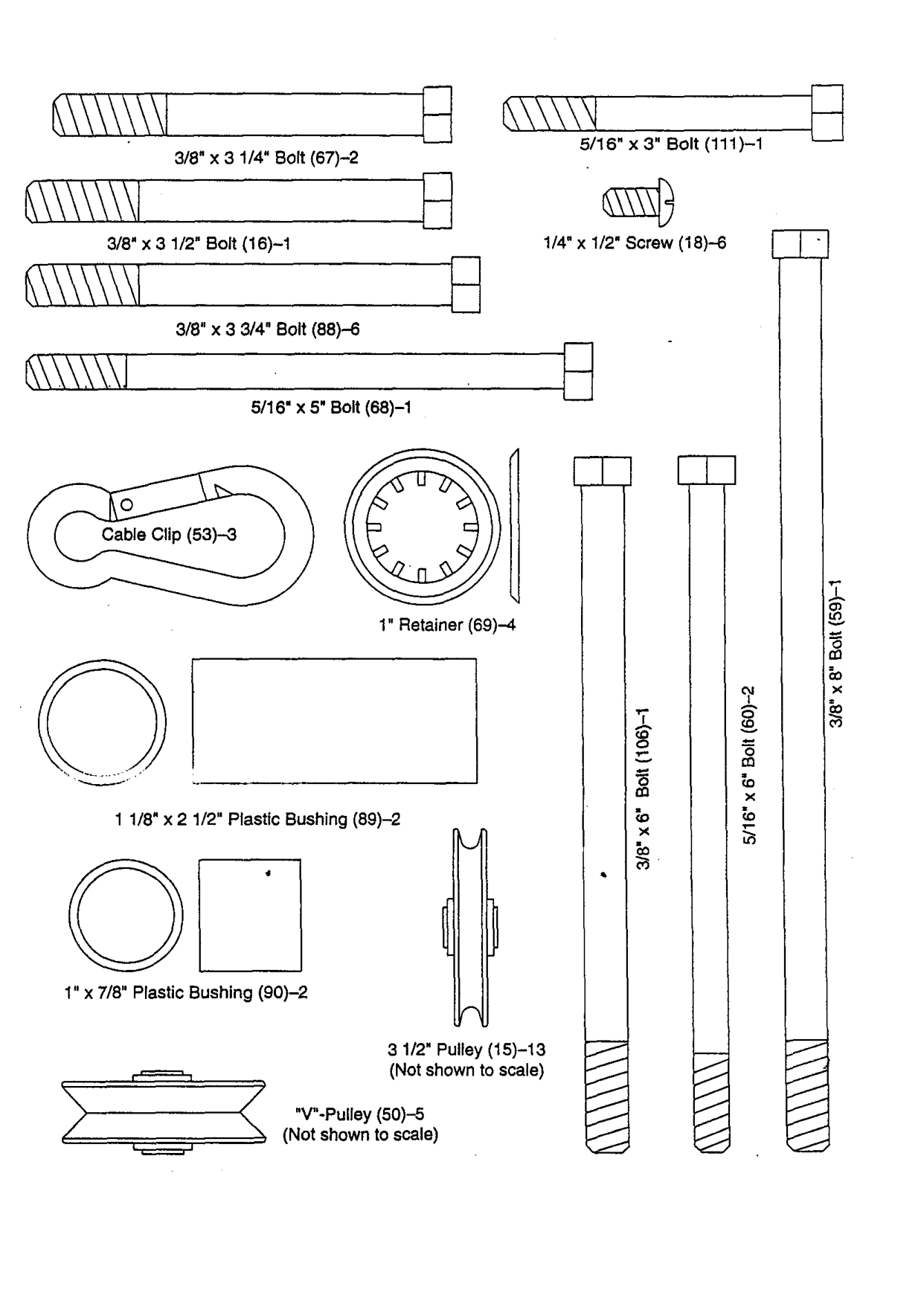
5/16" X 3" Bolt (111)-1
3/8" x 3 1/4" Bolt (67)-2
1/4" x 1/2" Screw (18)-6
3/8" x 3 1/2" Bolt (16)-1
3/8" x 3 3/4" Bolt (88)-6
################## 5/16" x 5' Bolt (68)-1
####### E
1" Retainer (69)-4
1 1/8" x 2 1/2" Plastic Bushing (89)-2
J
1" x 7/8" Plastic Bushing (90)-2
3 1/2" Pulley (15)-13 (Not shown to scale)
"V"-Pulley (50)-5
(Not shown to scale)

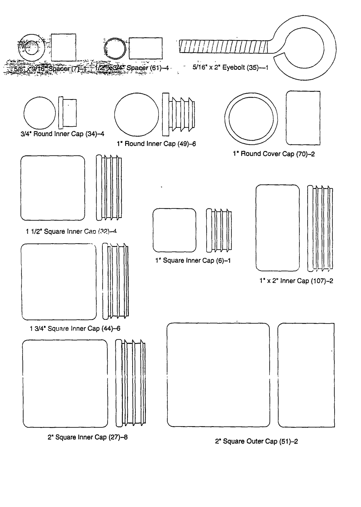
################ 5/16" x 2" Eyebolt (35)--1
3/4" Round inner Gap (34)--4
Round Inner Cap (49)-6
Round Cover Cap (70)-2
Square inner Cap (6)-1
x 2" Inner Cap (107)-2
3/4" Squ_re Inner Cap (44)--6
2" Square Inner Cap (27)-8 2" Square Outer Cap (51)-2