
Ask AI
— answers from the official manualAnswers from the official manual.
Common questions
Common Questions
20 totalWhat precautions should I take before opening the control box?
Before inspecting the inside of the control box, turn off the power and leave the unit turned off for at least 10 minutes. Check that the voltage of the electrolytic capacitor (inverter main circuit) has dropped to 20 VDC or less, as the unit may remain energized or hot after power is turned off. It will take approximately 10 minutes for the voltage to discharge after power off. (Page 15)
What type of refrigerant should I use for the PURY-HP72 system?
The PURY-HP72 uses R410A refrigerant exclusively. Do not use any other refrigerant type, as using the wrong refrigerant may cause the unit or pipes to burst, or result in explosion or fire. The system is designed specifically for R410A, which is a pseudo-azeotropic HFC blend. (Page 3)
How long should I wait before turning off the power after stopping operation?
Leave the unit turned on for at least 5 minutes after stopping operation before turning off the power. This prevents water leakage and malfunctions that could occur if power is turned off immediately. (Page 3)
What piping materials should be used for R410A refrigerant systems?
Use refrigerant pipes made of phosphorus deoxidized copper with specific radial thickness ratings depending on the pipe diameter. For pipes smaller than ø19.05 (3/4"), use 1/2H-material (Drawn) pipes unless the radial thickness is at least 1.2t. Keep the inner and outer surfaces clean and free of contaminants such as sulfur, oxides, dust, dirt, shaving particles, oil, and water. (Page 5)
How should refrigerant be charged into the system?
Refrigerant must be charged in the liquid state, not the gaseous state. If gaseous refrigerant is drawn out first, the composition of the remaining refrigerant will change and become unsuitable for use. When using a cylinder with a siphon, refrigerant is charged in the liquid state without needing to turn it upside down. (Page 14)
What is the required vacuum level for the system before refrigerant charging?
Use a vacuum pump that attains 0.5 Torr (65 Pa) or lower degree of vacuum after 5 minutes of operation. After the degree of vacuum has reached 5 Torr (650 Pa), evacuate for an additional 1 hour. Verify that the vacuum degree has not risen by more than 1 Torr (130 Pa) one hour after evacuation. (Page 12)
Show 14 more questions
What tools should not be used with R410A if they were previously used with R22?
How should the transmission cable be installed to avoid noise interference?
What is the maximum transmission line distance for M-NET systems?
What should be done if a leak detector cannot detect R410A refrigerant?
What does Error Code 2502 indicate on the PURY-HP72 and where can I find the troubleshooting steps?
How long should I wait before inspecting inside the control box after turning off the power?
How long before starting operation should I turn on the power to the PURY-HP72?
What type of refrigerant is used in the PURY-HP72 and can I substitute another refrigerant?
How many indoor units can be connected to the PURY-HP72 outdoor unit?
What is the correct vacuum level required during vacuum drying, and how long must I evacuate the system?
How should refrigerant R410A be charged into the system — in liquid or gas form?
What safety precautions must be taken when touching electrical components after the unit is stopped?
What is the maximum allowable transmission line distance between the outdoor unit and the farthest indoor unit?
What should I do if a refrigerant leak occurs — do I need to replace all the refrigerant?
Full Manual
371 pages
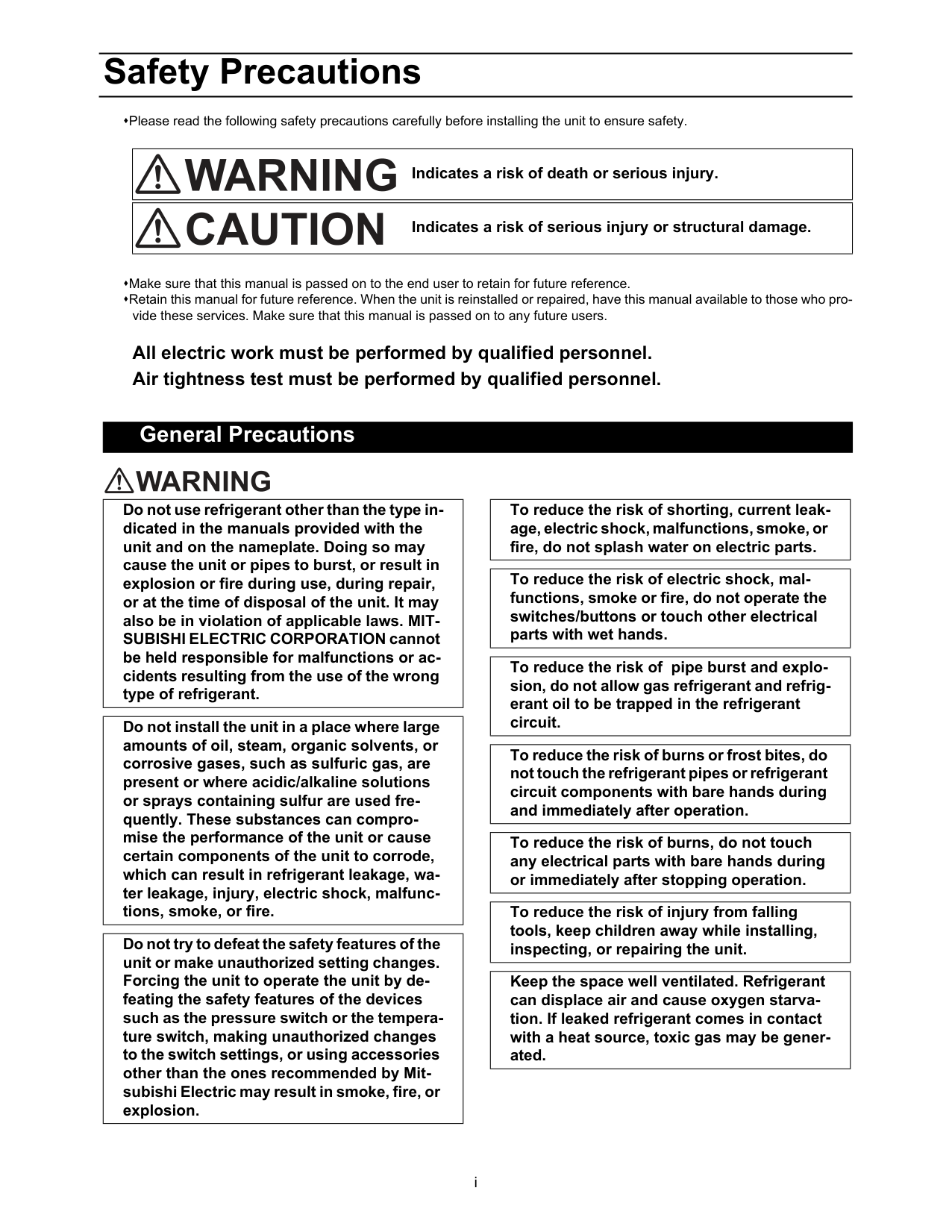
i Safety Precautions Please read the following safety precautions carefully before installing the unit to ensure safety. Make sure that this manual is passed on to the end user to retain for future reference. Retain this manual for future reference. When the unit is reinstalled or repaired, have this manual available to those who pro- vide these services. Make sure that this manual is passed on to any future users. All electric work must be performed by qualified personnel. Air tightness test must be performed by qualified personnel. [1] General Precautions Indicates a risk of death or serious injury. Indicates a risk of serious injury or structural damage. General Precautions Do not use refrigerant other than the type in- dicated in the manuals provided with the unit and on the nameplate. Doing so may cause the unit or pipes to burst, or result in explosion or fire during use, during repair, or at the time of disposal of the unit. It may also be in violation of applicable laws. MIT- SUBISHI ELECTRIC CORPORATION cannot be held responsible for malfunctions or ac- cidents resulting from the use of the wrong type of refrigerant. Do not install the unit in a place where large amounts of oil, steam, organic solvents, or corrosive gases, such as sulfuric gas, are present or where acidic/alkaline solutions or sprays containing sulfur are used fre- quently. These substances can compro- mise the performance of the unit or cause certain components of the unit to corrode, which can result in refrigerant leakage, wa- ter leakage, injury, electric shock, malfunc- tions, smoke, or fire. Do not try to defeat the safety features of the unit or make unauthorized setting changes. Forcing the unit to operate the unit by de- feating the safety features of the devices such as the pressure switch or the tempera- ture switch, making unauthorized changes to the switch settings, or using accessories other than the ones recommended by Mit- subishi Electric may result in smoke, fire, or explosion. To reduce the risk of shorting, current leak- age, electric shock, malfunctions, smoke, or fire, do not splash water on electric parts. To reduce the risk of electric shock, mal- functions, smoke or fire, do not operate the switches/buttons or touch other electrical parts with wet hands. To reduce the risk of pipe burst and explo- sion, do not allow gas refrigerant and refrig- erant oil to be trapped in the refrigerant circuit. To reduce the risk of burns or frost bites, do not touch the refrigerant pipes or refrigerant circuit components with bare hands during and immediately after operation. To reduce the risk of burns, do not touch any electrical parts with bare hands during or immediately after stopping operation. To reduce the risk of injury from falling tools, keep children away while installing, inspecting, or repairing the unit. Keep the space well ventilated. Refrigerant can displace air and cause oxygen starva- tion. If leaked refrigerant comes in contact with a heat source, toxic gas may be gener- ated.
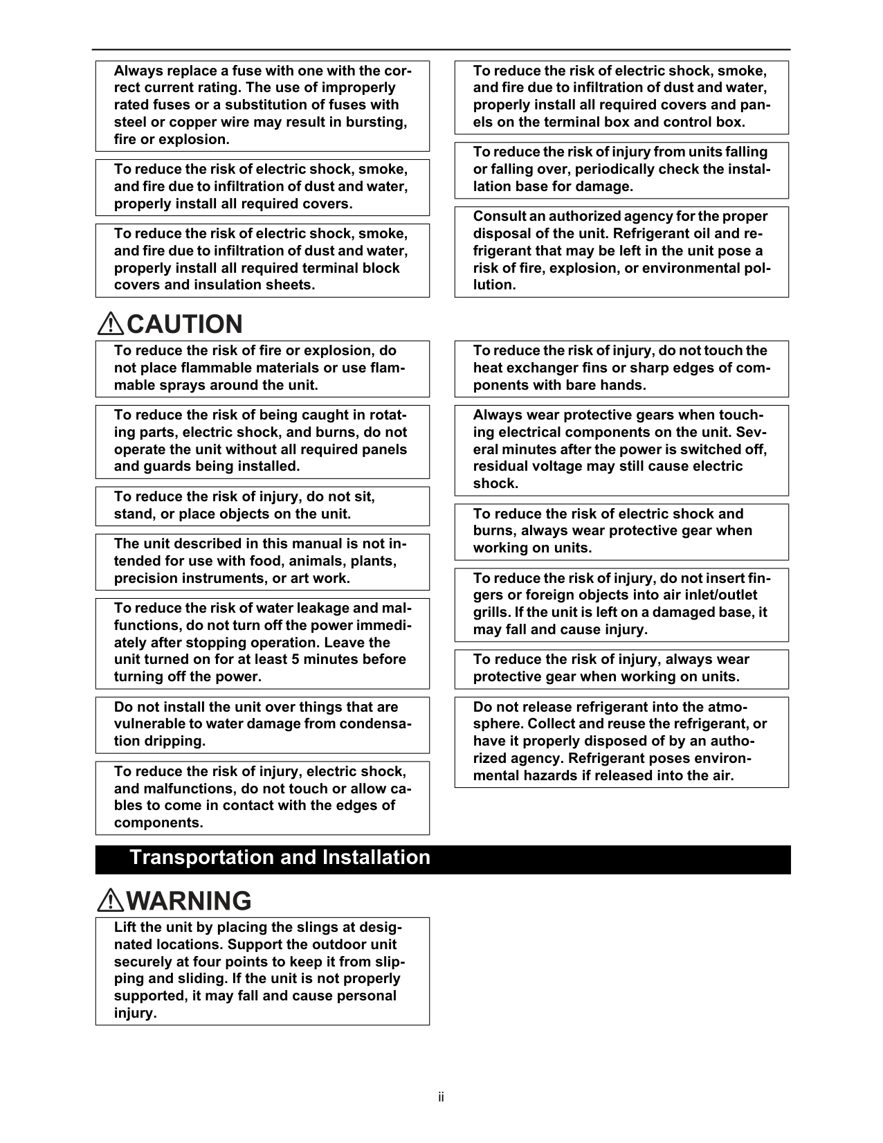
ii [2] Transportation and Installation Always replace a fuse with one with the cor- rect current rating. The use of improperly rated fuses or a substitution of fuses with steel or copper wire may result in bursting, fire or explosion. To reduce the risk of electric shock, smoke, and fire due to infiltration of dust and water, properly install all required covers. To reduce the risk of electric shock, smoke, and fire due to infiltration of dust and water, properly install all required terminal block covers and insulation sheets. To reduce the risk of electric shock, smoke, and fire due to infiltration of dust and water, properly install all required covers and pan- els on the terminal box and control box. To reduce the risk of injury from units falling or falling over, periodically check the instal- lation base for damage. Consult an authorized agency for the proper disposal of the unit. Refrigerant oil and re- frigerant that may be left in the unit pose a risk of fire, explosion, or environmental pol- lution. To reduce the risk of fire or explosion, do not place flammable materials or use flam- mable sprays around the unit. To reduce the risk of being caught in rotat- ing parts, electric shock, and burns, do not operate the unit without all required panels and guards being installed. To reduce the risk of injury, do not sit, stand, or place objects on the unit. The unit described in this manual is not in- tended for use with food, animals, plants, precision instruments, or art work. To reduce the risk of water leakage and mal- functions, do not turn off the power immedi- ately after stopping operation. Leave the unit turned on for at least 5 minutes before turning off the power. Do not install the unit over things that are vulnerable to water damage from condensa- tion dripping. To reduce the risk of injury, electric shock, and malfunctions, do not touch or allow ca- bles to come in contact with the edges of components. To reduce the risk of injury, do not touch the heat exchanger fins or sharp edges of com- ponents with bare hands. Always wear protective gears when touch- ing electrical components on the unit. Sev- eral minutes after the power is switched off, residual voltage may still cause electric shock. To reduce the risk of electric shock and burns, always wear protective gear when working on units. To reduce the risk of injury, do not insert fin- gers or foreign objects into air inlet/outlet grills. If the unit is left on a damaged base, it may fall and cause injury. To reduce the risk of injury, always wear protective gear when working on units. Do not release refrigerant into the atmo- sphere. Collect and reuse the refrigerant, or have it properly disposed of by an autho- rized agency. Refrigerant poses environ- mental hazards if released into the air. Transportation and Installation Lift the unit by placing the slings at desig- nated locations. Support the outdoor unit securely at four points to keep it from slip- ping and sliding. If the unit is not properly supported, it may fall and cause personal injury.
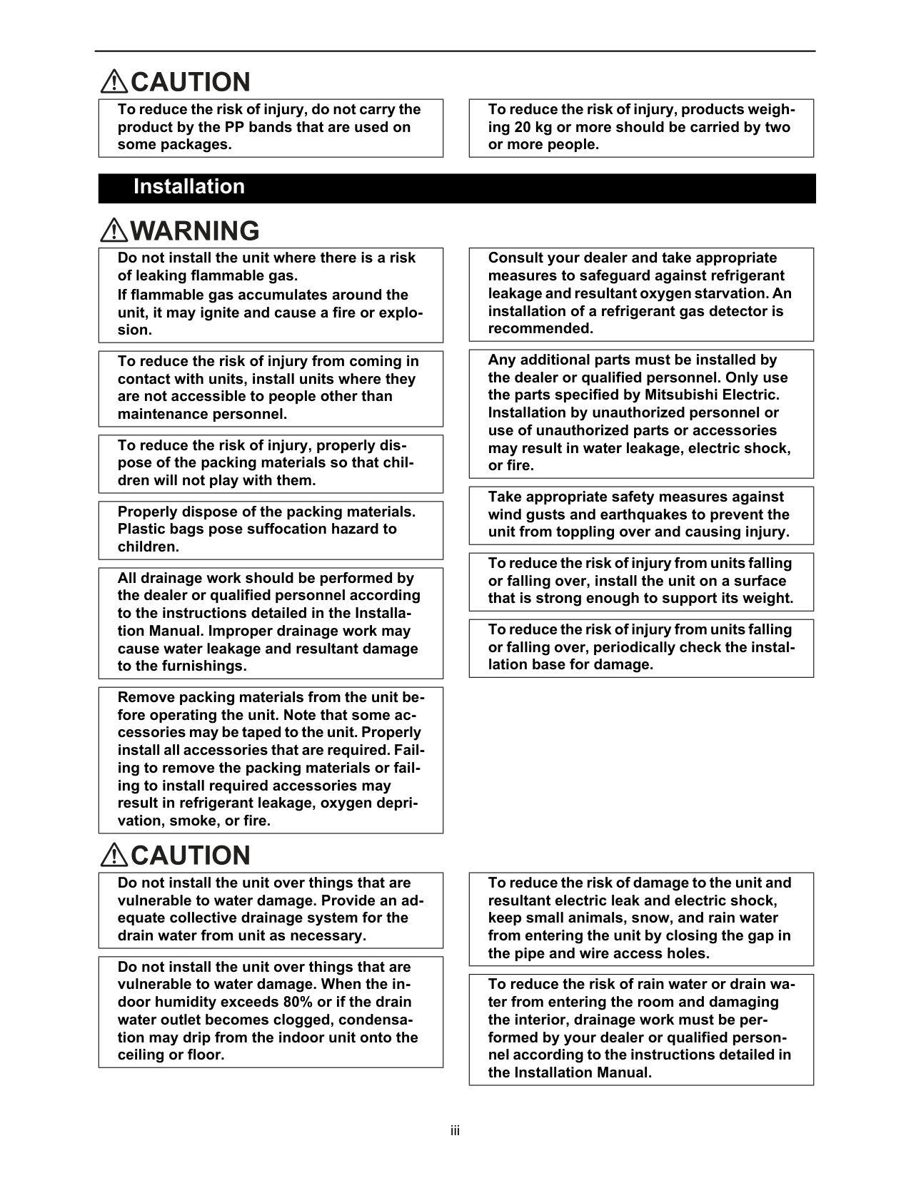
iii [3] Installation To reduce the risk of injury, do not carry the product by the PP bands that are used on some packages. To reduce the risk of injury, products weigh- ing 20 kg or more should be carried by two or more people. Installation Do not install the unit where there is a risk of leaking flammable gas. If flammable gas accumulates around the unit, it may ignite and cause a fire or explo- sion. To reduce the risk of injury from coming in contact with units, install units where they are not accessible to people other than maintenance personnel. To reduce the risk of injury, properly dis- pose of the packing materials so that chil- dren will not play with them. Properly dispose of the packing materials. Plastic bags pose suffocation hazard to children. All drainage work should be performed by the dealer or qualified personnel according to the instructions detailed in the Installa- tion Manual. Improper drainage work may cause water leakage and resultant damage to the furnishings. Remove packing materials from the unit be- fore operating the unit. Note that some ac- cessories may be taped to the unit. Properly install all accessories that are required. Fail- ing to remove the packing materials or fail- ing to install required accessories may result in refrigerant leakage, oxygen depri- vation, smoke, or fire. Consult your dealer and take appropriate measures to safeguard against refrigerant leakage and resultant oxygen starvation. An installation of a refrigerant gas detector is recommended. Any additional parts must be installed by the dealer or qualified personnel. Only use the parts specified by Mitsubishi Electric. Installation by unauthorized personnel or use of unauthorized parts or accessories may result in water leakage, electric shock, or fire. Take appropriate safety measures against wind gusts and earthquakes to prevent the unit from toppling over and causing injury. To reduce the risk of injury from units falling or falling over, install the unit on a surface that is strong enough to support its weight. To reduce the risk of injury from units falling or falling over, periodically check the instal- lation base for damage. Do not install the unit over things that are vulnerable to water damage. Provide an ad- equate collective drainage system for the drain water from unit as necessary. Do not install the unit over things that are vulnerable to water damage. When the in- door humidity exceeds 80% or if the drain water outlet becomes clogged, condensa- tion may drip from the indoor unit onto the ceiling or floor. To reduce the risk of damage to the unit and resultant electric leak and electric shock, keep small animals, snow, and rain water from entering the unit by closing the gap in the pipe and wire access holes. To reduce the risk of rain water or drain wa- ter from entering the room and damaging the interior, drainage work must be per- formed by your dealer or qualified person- nel according to the instructions detailed in the Installation Manual.
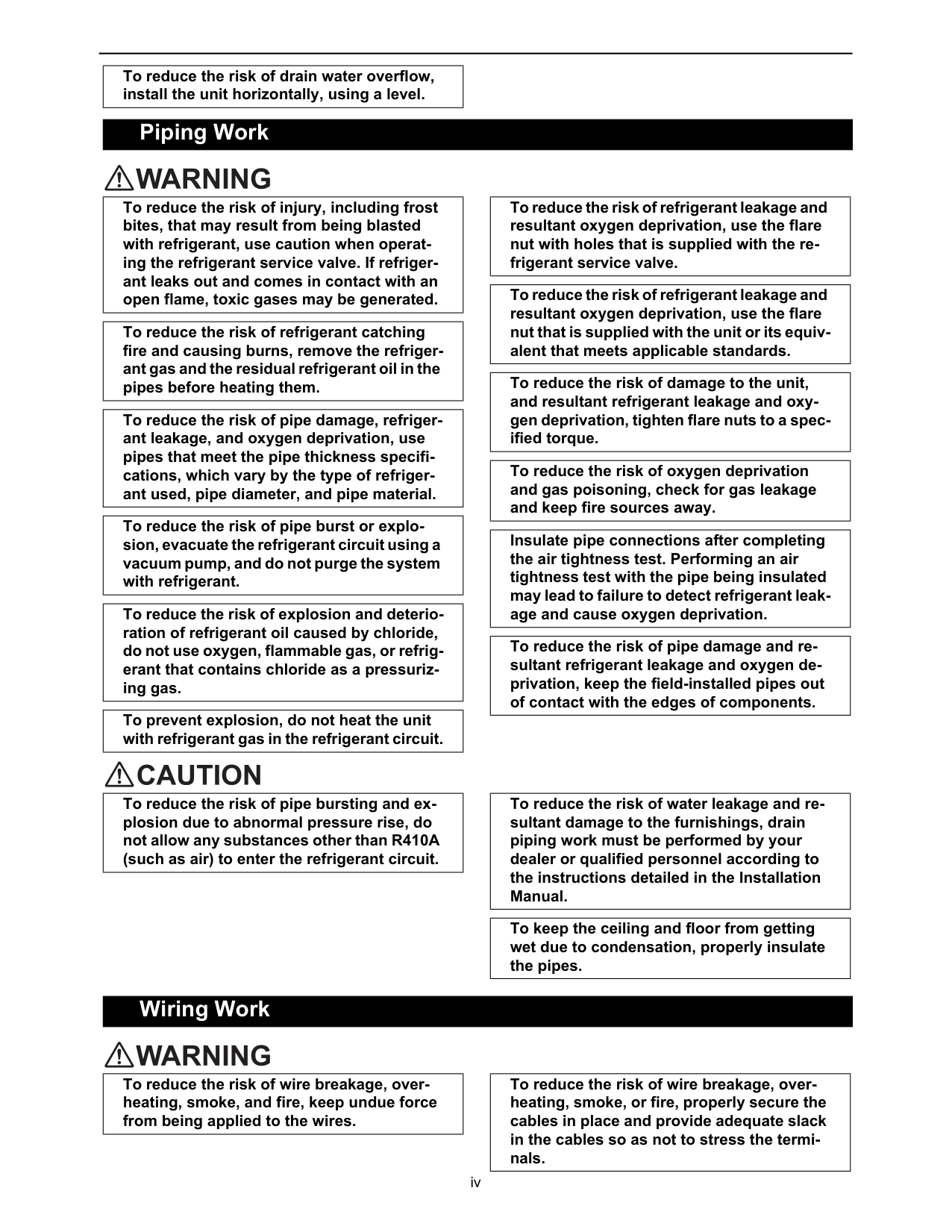
iv [4] Piping Work [5] Wiring Work To reduce the risk of drain water overflow, install the unit horizontally, using a level. Piping Work To reduce the risk of injury, including frost bites, that may result from being blasted with refrigerant, use caution when operat- ing the refrigerant service valve. If refriger- ant leaks out and comes in contact with an open flame, toxic gases may be generated. To reduce the risk of refrigerant catching fire and causing burns, remove the refriger- ant gas and the residual refrigerant oil in the pipes before heating them. To reduce the risk of pipe damage, refriger- ant leakage, and oxygen deprivation, use pipes that meet the pipe thickness specifi- cations, which vary by the type of refriger- ant used, pipe diameter, and pipe material. To reduce the risk of pipe burst or explo- sion, evacuate the refrigerant circuit using a vacuum pump, and do not purge the system with refrigerant. To reduce the risk of explosion and deterio- ration of refrigerant oil caused by chloride, do not use oxygen, flammable gas, or refrig- erant that contains chloride as a pressuriz- ing gas. To prevent explosion, do not heat the unit with refrigerant gas in the refrigerant circuit. To reduce the risk of refrigerant leakage and resultant oxygen deprivation, use the flare nut with holes that is supplied with the re- frigerant service valve. To reduce the risk of refrigerant leakage and resultant oxygen deprivation, use the flare nut that is supplied with the unit or its equiv- alent that meets applicable standards. To reduce the risk of damage to the unit, and resultant refrigerant leakage and oxy- gen deprivation, tighten flare nuts to a spec- ified torque. To reduce the risk of oxygen deprivation and gas poisoning, check for gas leakage and keep fire sources away. Insulate pipe connections after completing the air tightness test. Performing an air tightness test with the pipe being insulated may lead to failure to detect refrigerant leak- age and cause oxygen deprivation. To reduce the risk of pipe damage and re- sultant refrigerant leakage and oxygen de- privation, keep the field-installed pipes out of contact with the edges of components. To reduce the risk of pipe bursting and ex- plosion due to abnormal pressure rise, do not allow any substances other than R410A (such as air) to enter the refrigerant circuit. To reduce the risk of water leakage and re- sultant damage to the furnishings, drain piping work must be performed by your dealer or qualified personnel according to the instructions detailed in the Installation Manual. To keep the ceiling and floor from getting wet due to condensation, properly insulate the pipes. Wiring Work To reduce the risk of wire breakage, over- heating, smoke, and fire, keep undue force from being applied to the wires. To reduce the risk of wire breakage, over- heating, smoke, or fire, properly secure the cables in place and provide adequate slack in the cables so as not to stress the termi- nals.
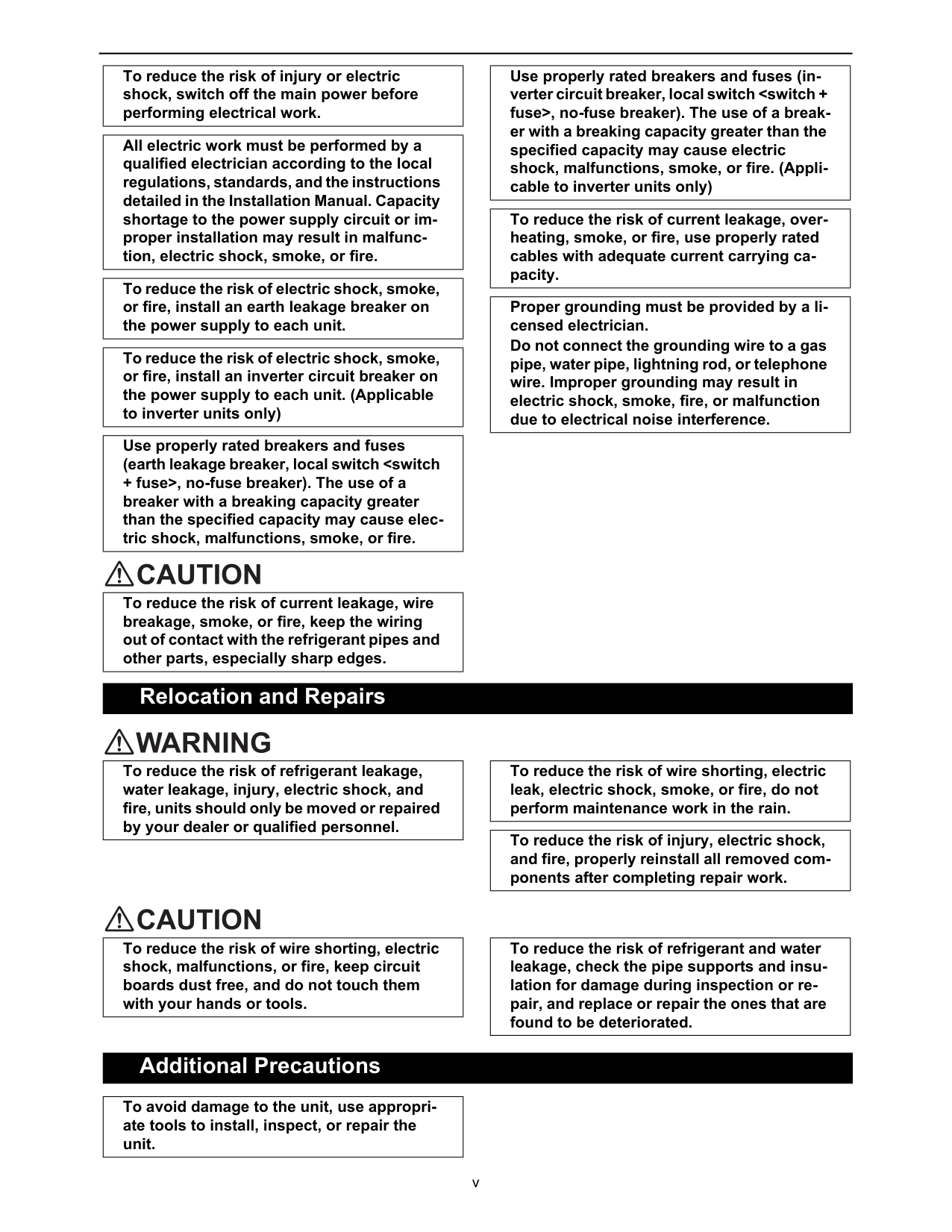
v [6] Relocation and Repairs [7] Additional Precautions To reduce the risk of injury or electric shock, switch off the main power before performing electrical work. All electric work must be performed by a qualified electrician according to the local regulations, standards, and the instructions detailed in the Installation Manual. Capacity shortage to the power supply circuit or im- proper installation may result in malfunc- tion, electric shock, smoke, or fire. To reduce the risk of electric shock, smoke, or fire, install an earth leakage breaker on the power supply to each unit. To reduce the risk of electric shock, smoke, or fire, install an inverter circuit breaker on the power supply to each unit. (Applicable to inverter units only) Use properly rated breakers and fuses (earth leakage breaker, local switch
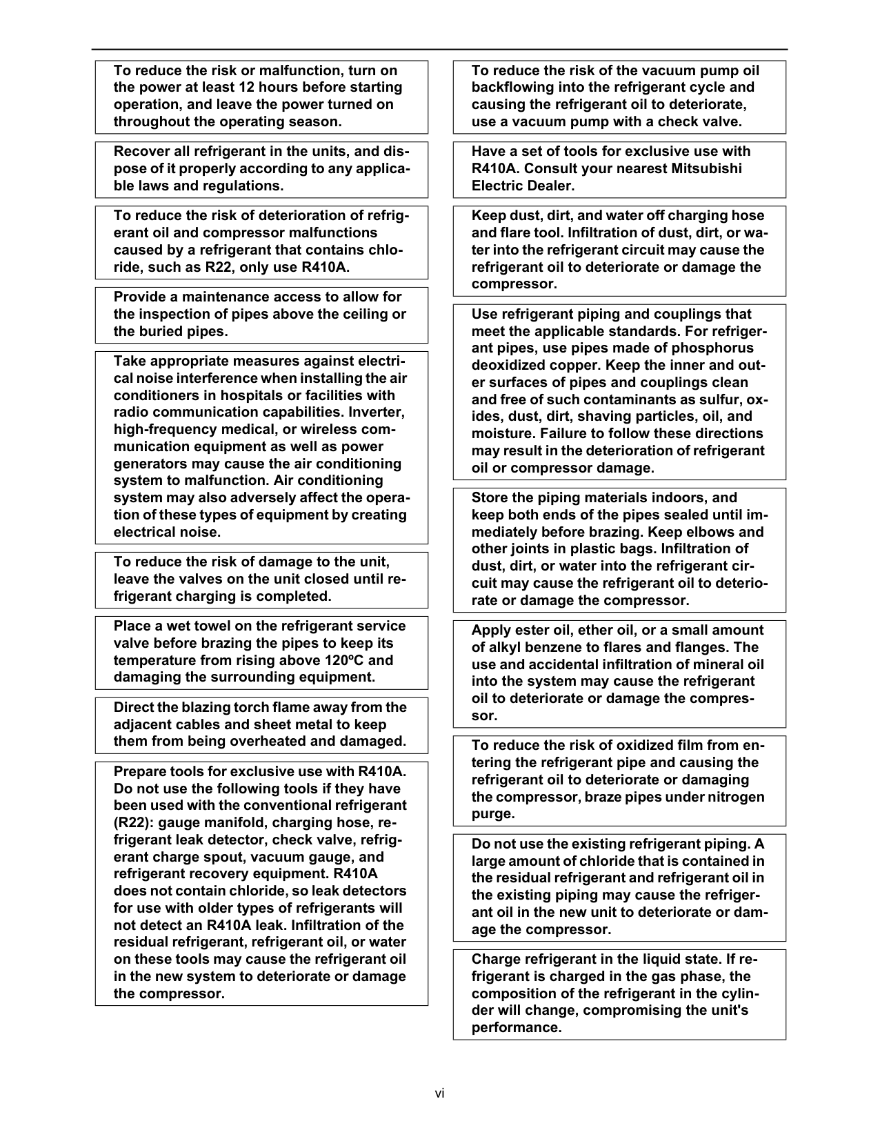
vi To reduce the risk or malfunction, turn on the power at least 12 hours before starting operation, and leave the power turned on throughout the operating season. Recover all refrigerant in the units, and dis- pose of it properly according to any applica- ble laws and regulations. To reduce the risk of deterioration of refrig- erant oil and compressor malfunctions caused by a refrigerant that contains chlo- ride, such as R22, only use R410A. Provide a maintenance access to allow for the inspection of pipes above the ceiling or the buried pipes. Take appropriate measures against electri- cal noise interference when installing the air conditioners in hospitals or facilities with radio communication capabilities. Inverter, high-frequency medical, or wireless com- munication equipment as well as power generators may cause the air conditioning system to malfunction. Air conditioning system may also adversely affect the opera- tion of these types of equipment by creating electrical noise. To reduce the risk of damage to the unit, leave the valves on the unit closed until re- frigerant charging is completed. Place a wet towel on the refrigerant service valve before brazing the pipes to keep its temperature from rising above 120ºC and damaging the surrounding equipment. Direct the blazing torch flame away from the adjacent cables and sheet metal to keep them from being overheated and damaged. Prepare tools for exclusive use with R410A. Do not use the following tools if they have been used with the conventional refrigerant (R22): gauge manifold, charging hose, re- frigerant leak detector, check valve, refrig- erant charge spout, vacuum gauge, and refrigerant recovery equipment. R410A does not contain chloride, so leak detectors for use with older types of refrigerants will not detect an R410A leak. Infiltration of the residual refrigerant, refrigerant oil, or water on these tools may cause the refrigerant oil in the new system to deteriorate or damage the compressor. To reduce the risk of the vacuum pump oil backflowing into the refrigerant cycle and causing the refrigerant oil to deteriorate, use a vacuum pump with a check valve. Have a set of tools for exclusive use with R410A. Consult your nearest Mitsubishi Electric Dealer. Keep dust, dirt, and water off charging hose and flare tool. Infiltration of dust, dirt, or wa- ter into the refrigerant circuit may cause the refrigerant oil to deteriorate or damage the compressor. Use refrigerant piping and couplings that meet the applicable standards. For refriger- ant pipes, use pipes made of phosphorus deoxidized copper. Keep the inner and out- er surfaces of pipes and couplings clean and free of such contaminants as sulfur, ox- ides, dust, dirt, shaving particles, oil, and moisture. Failure to follow these directions may result in the deterioration of refrigerant oil or compressor damage. Store the piping materials indoors, and keep both ends of the pipes sealed until im- mediately before brazing. Keep elbows and other joints in plastic bags. Infiltration of dust, dirt, or water into the refrigerant cir- cuit may cause the refrigerant oil to deterio- rate or damage the compressor. Apply ester oil, ether oil, or a small amount of alkyl benzene to flares and flanges. The use and accidental infiltration of mineral oil into the system may cause the refrigerant oil to deteriorate or damage the compres- sor. To reduce the risk of oxidized film from en- tering the refrigerant pipe and causing the refrigerant oil to deteriorate or damaging the compressor, braze pipes under nitrogen purge. Do not use the existing refrigerant piping. A large amount of chloride that is contained in the residual refrigerant and refrigerant oil in the existing piping may cause the refriger- ant oil in the new unit to deteriorate or dam- age the compressor. Charge refrigerant in the liquid state. If re- frigerant is charged in the gas phase, the composition of the refrigerant in the cylin- der will change, compromising the unit's performance.
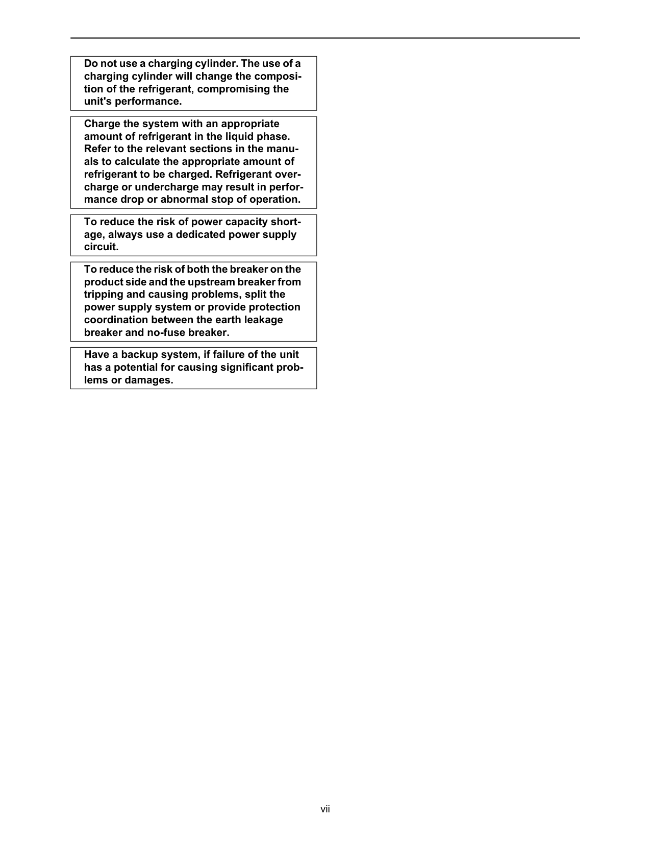
vii Do not use a charging cylinder. The use of a charging cylinder will change the composi- tion of the refrigerant, compromising the unit's performance. Charge the system with an appropriate amount of refrigerant in the liquid phase. Refer to the relevant sections in the manu- als to calculate the appropriate amount of refrigerant to be charged. Refrigerant over- charge or undercharge may result in perfor- mance drop or abnormal stop of operation. To reduce the risk of power capacity short- age, always use a dedicated power supply circuit. To reduce the risk of both the breaker on the product side and the upstream breaker from tripping and causing problems, split the power supply system or provide protection coordination between the earth leakage breaker and no-fuse breaker. Have a backup system, if failure of the unit has a potential for causing significant prob- lems or damages.
Contents
Hwe13080
Gb
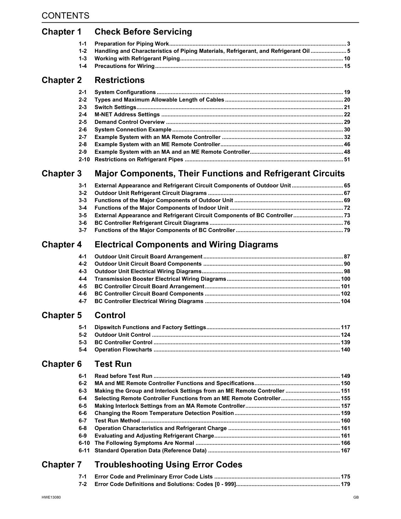
Chapter 1 Check Before Servicing 1-1 Preparation for Piping Work.................................................................................................................. 3 1-2 Handling and Characteristics of Piping Materials, Refrigerant, and Refrigerant Oil ....................... 5 1-3 Working with Refrigerant Piping......................................................................................................... 10 1-4 Precautions for Wiring......................................................................................................................... 15 Chapter 2 Restrictions 2-1 System Configurations ........................................................................................................................ 19 2-2 Types and Maximum Allowable Length of Cables ............................................................................ 20 2-3 Switch Settings..................................................................................................................................... 21 2-4 M-NET Address Settings ..................................................................................................................... 22 2-5 Demand Control Overview .................................................................................................................. 29 2-6 System Connection Example .............................................................................................................. 30 2-7 Example System with an MA Remote Controller .............................................................................. 32 2-8 Example System with an ME Remote Controller............................................................................... 46 2-9 Example System with an MA and an ME Remote Controller............................................................ 48 2-10 Restrictions on Refrigerant Pipes ...................................................................................................... 51 Chapter 3 Major Components, Their Functions and Refrigerant Circuits 3-1 External Appearance and Refrigerant Circuit Components of Outdoor Unit ................................. 65 3-2 Outdoor Unit Refrigerant Circuit Diagrams ....................................................................................... 67 3-3 Functions of the Major Components of Outdoor Unit ...................................................................... 69 3-4 Functions of the Major Components of Indoor Unit ......................................................................... 72 3-5 External Appearance and Refrigerant Circuit Components of BC Controller................................ 73 3-6 BC Controller Refrigerant Circuit Diagrams ...................................................................................... 76 3-7 Functions of the Major Components of BC Controller ..................................................................... 79 Chapter 4 Electrical Components and Wiring Diagrams 4-1 Outdoor Unit Circuit Board Arrangement .......................................................................................... 87 4-2 Outdoor Unit Circuit Board Components .......................................................................................... 90 4-3 Outdoor Unit Electrical Wiring Diagrams........................................................................................... 98 4-4 Transmission Booster Electrical Wiring Diagrams......................................................................... 100 4-5 BC Controller Circuit Board Arrangement....................................................................................... 101 4-6 BC Controller Circuit Board Components ....................................................................................... 102 4-7 BC Controller Electrical Wiring Diagrams ....................................................................................... 104 Chapter 5 Control 5-1 Dipswitch Functions and Factory Settings...................................................................................... 117 5-2 Outdoor Unit Control ......................................................................................................................... 124 5-3 BC Controller Control ........................................................................................................................ 139 5-4 Operation Flowcharts ........................................................................................................................ 140 Chapter 6 Test Run 6-1 Read before Test Run ........................................................................................................................ 149 6-2 MA and ME Remote Controller Functions and Specifications....................................................... 150 6-3 Making the Group and Interlock Settings from an ME Remote Controller ................................... 151 6-4 Selecting Remote Controller Functions from an ME Remote Controller...................................... 155 6-5 Making Interlock Settings from an MA Remote Controller............................................................. 157 6-6 Changing the Room Temperature Detection Position.................................................................... 159 6-7 Test Run Method ................................................................................................................................ 160 6-8 Operation Characteristics and Refrigerant Charge ........................................................................ 161 6-9 Evaluating and Adjusting Refrigerant Charge.................................................................................161 6-10 The Following Symptoms Are Normal ............................................................................................. 166 6-11 Standard Operation Data (Reference Data) ..................................................................................... 167 Chapter 7 Troubleshooting Using Error Codes 7-1 Error Code and Preliminary Error Code Lists .................................................................................175 7-2 Error Code Definitions and Solutions: Codes [0 - 999]................................................................... 179
Contents
Hwe13080
Gb
7-3 Error Code Definitions and Solutions: Codes [1000 - 1999]........................................................... 180 7-4 Error Code Definitions and Solutions: Codes [2000 - 2999]........................................................... 184 7-5 Error Code Definitions and Solutions: Codes [3000 - 3999]........................................................... 191 7-6 Error Code Definitions and Solutions: Codes [4000 - 4999]........................................................... 192 7-7 Error Code Definitions and Solutions: Codes [5000 - 5999]........................................................... 210 7-8 Error Code Definitions and Solutions: Codes [6000 - 6999]........................................................... 223 7-9 Error Code Definitions and Solutions: Codes [7000 - 7999]........................................................... 239 Chapter 8 Troubleshooting Based on Observed Symptoms 8-1 MA Remote Controller Problems ...................................................................................................... 251 8-2 ME remote Controller Problems ....................................................................................................... 255 8-3 Refrigerant Control Problems ........................................................................................................... 259 8-4 Checking Transmission Waveform and for Electrical Noise Interference.................................... 264 8-5 Pressure Sensor Circuit Configuration and Troubleshooting Pressure Sensor Problems ........ 267 8-6 Troubleshooting Solenoid Valve Problems ..................................................................................... 269 8-7 Troubleshooting Outdoor Unit Fan Problems ................................................................................. 272 8-8 Troubleshooting LEV Problems........................................................................................................ 273 8-9 Troubleshooting Problems with Major Components on BC Controller ........................................ 277 8-10 Troubleshooting Inverter Problems (TKMU).................................................................................... 288 8-11 Troubleshooting Inverter Problems (YKMU) ................................................................................... 298 8-12 Control Circuit (TKMU) ...................................................................................................................... 307 8-13 Control Circuit (YKMU) ...................................................................................................................... 309 8-14 Measures for Refrigerant Leakage ................................................................................................... 311 8-15 Compressor Replacement Instructions ........................................................................................... 313 8-16 Solenoid Valve Block and Check Valve Replacement Instructions .............................................. 315 8-17 BC Controller Maintenance Instructions.......................................................................................... 319 8-18 Troubleshooting Problems Using the LED Status Indicators on the Outdoor Unit..................... 322 Chapter 9 LED Status Indicators on the Outdoor Unit Circuit Board 9-1 LED Status Indicators ........................................................................................................................ 325 9-2 LED Status Indicators Table ............................................................................................................. 328
Hwe13080
Gb
Chapter 1 Check Before Servicing 1-1 Preparation for Piping Work ................................................................................................................ 3 1-1-1 Read before Servicing ............................................................................................................................ 3 1-1-2 Tool Preparation ..................................................................................................................................... 4 1-2 Handling and Characteristics of Piping Materials, Refrigerant, and Refrigerant Oil...................... 5 1-2-1 Piping Materials ...................................................................................................................................... 5 1-2-2 Storage of Piping Materials..................................................................................................................... 7 1-2-3 Pipe Processing...................................................................................................................................... 7 1-2-4 Characteristics of the New and Conventional Refrigerants .................................................................... 8 1-2-5 Refrigerant Oil......................................................................................................................................... 9 1-3 Working with Refrigerant Piping ....................................................................................................... 10 1-3-1 Pipe Brazing.......................................................................................................................................... 10 1-3-2 Air Tightness Test................................................................................................................................. 11 1-3-3 Vacuum Drying ..................................................................................................................................... 12 1-3-4 Refrigerant Charging............................................................................................................................. 14 1-4 Precautions for Wiring ....................................................................................................................... 15
Hwe13080
Gb
[1-1 Preparation for Piping Work ]
Hwe13080
Gb
1 Check Before Servicing 1 Check Before Servicing 1-1 Preparation for Piping Work 1-1-1 Read before ServicingCaution
Install new pipes immediately after removing old ones to keep moisture out of the refrigerant circuit. The use of refrigerant that contains chloride, such as R22, will cause the refrigerating machine oil to deteriorate.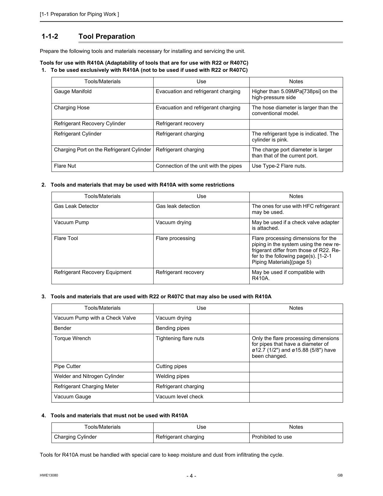
[1-1 Preparation for Piping Work ]
Hwe13080
Gb
1-1-2 Tool Preparation Prepare the following tools and materials necessary for installing and servicing the unit. Tools for use with R410A (Adaptability of tools that are for use with R22 or R407C)R410A.
Tools/Materials Use Notes Vacuum Pump with a Check Valve Vacuum drying Bender Bending pipes Torque Wrench Tightening flare nuts Only the flare processing dimensions for pipes that have a diameter of ø12.7 (1/2") and ø15.88 (5/8") have been changed. Pipe Cutter Cutting pipes Welder and Nitrogen Cylinder Welding pipes Refrigerant Charging Meter Refrigerant charging Vacuum Gauge Vacuum level check Tools/Materials Use Notes Charging Cylinder Refrigerant charging Prohibited to use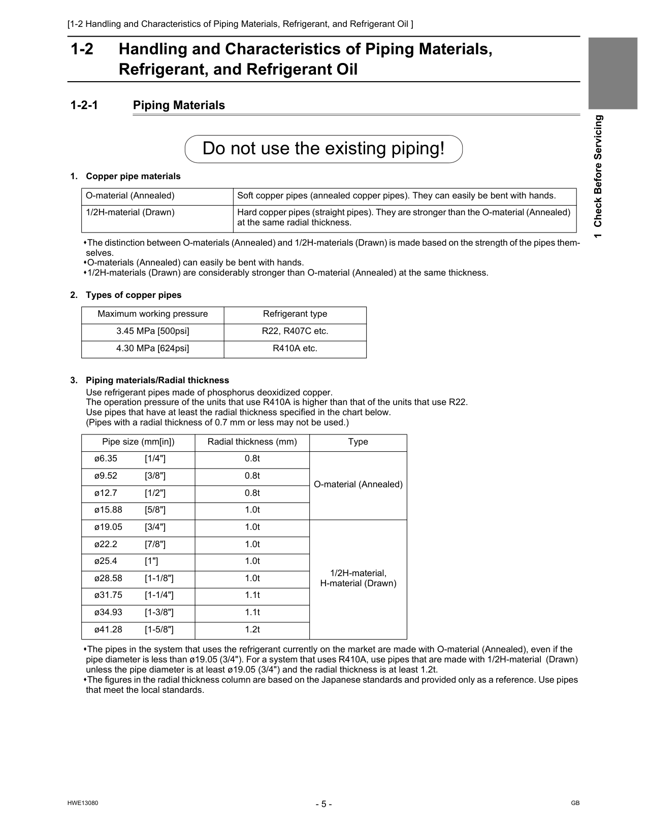
[1-2 Handling and Characteristics of Piping Materials, Refrigerant, and Refrigerant Oil ]
Hwe13080
Gb
1 Check Before Servicing 1-2 Handling and Characteristics of Piping Materials, Refrigerant, and Refrigerant Oil 1-2-1 Piping Materials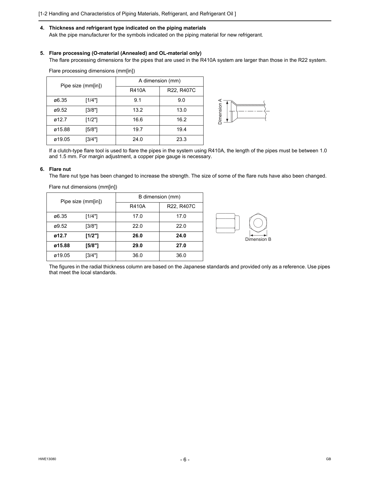
[1-2 Handling and Characteristics of Piping Materials, Refrigerant, and Refrigerant Oil ]
Hwe13080
Gb
R410A
R22, R407C
ø6.35 [1/4"] 9.1 9.0 ø9.52 [3/8"] 13.2 13.0 ø12.7 [1/2"] 16.6 16.2 ø15.88 [5/8"] 19.7 19.4 ø19.05 [3/4"] 24.0 23.3 Flare nut dimensions (mm[in]) Pipe size (mm[in]) B dimension (mm)R410A
R22, R407C
ø6.35 [1/4"] 17.0 17.0 ø9.52 [3/8"] 22.0 22.0 ø12.7 [1/2"] 26.0 24.0 ø15.88 [5/8"] 29.0 27.0 ø19.05 [3/4"] 36.0 36.0 Dimension A Dimension B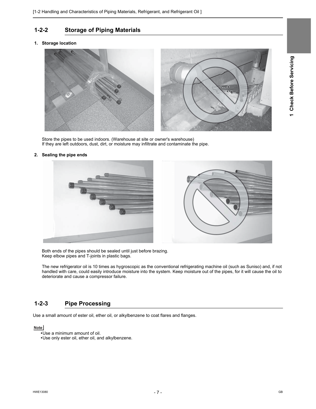
[1-2 Handling and Characteristics of Piping Materials, Refrigerant, and Refrigerant Oil ]
Hwe13080
Gb
1 Check Before Servicing 1-2-2 Storage of Piping Materials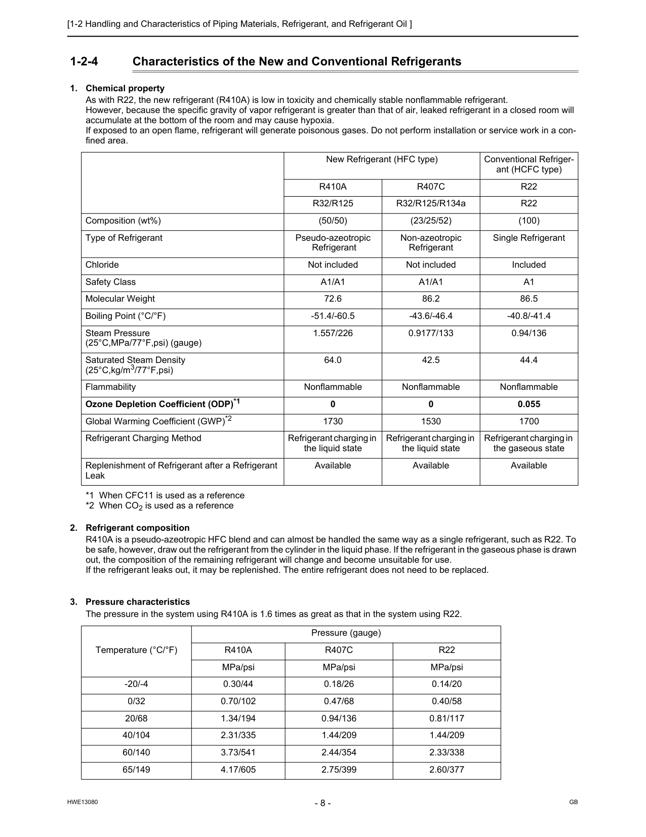
[1-2 Handling and Characteristics of Piping Materials, Refrigerant, and Refrigerant Oil ]
Hwe13080
Gb
1-2-4 Characteristics of the New and Conventional RefrigerantsR410A
R407C
R22
R32/R125
R32/R125/R134aR22
Composition (wt%) (50/50) (23/25/52) (100) Type of Refrigerant Pseudo-azeotropic Refrigerant Non-azeotropic Refrigerant Single Refrigerant Chloride Not included Not included Included Safety ClassA1/A1
A1/A1
A1
Molecular Weight 72.6 86.2 86.5 Boiling Point (°C/°F) -51.4/-60.5 -43.6/-46.4 -40.8/-41.4 Steam Pressure (25°C,MPa/77°F,psi) (gauge) 1.557/226 0.9177/133 0.94/136 Saturated Steam Density (25°C,kg/m3/77°F,psi) 64.0 42.5 44.4 Flammability Nonflammable Nonflammable Nonflammable Ozone Depletion Coefficient (ODP)*1 0 0 0.055 Global Warming Coefficient (GWP)*2 1730 1530 1700 Refrigerant Charging Method Refrigerant charging in the liquid state Refrigerant charging in the liquid state Refrigerant charging in the gaseous state Replenishment of Refrigerant after a Refrigerant Leak Available Available Available Temperature (°C/°F) Pressure (gauge)R410A
R407C
R22
MPa/psi MPa/psi MPa/psi -20/-4 0.30/44 0.18/26 0.14/20 0/32 0.70/102 0.47/68 0.40/58 20/68 1.34/194 0.94/136 0.81/117 40/104 2.31/335 1.44/209 1.44/209 60/140 3.73/541 2.44/354 2.33/338 65/149 4.17/605 2.75/399 2.60/377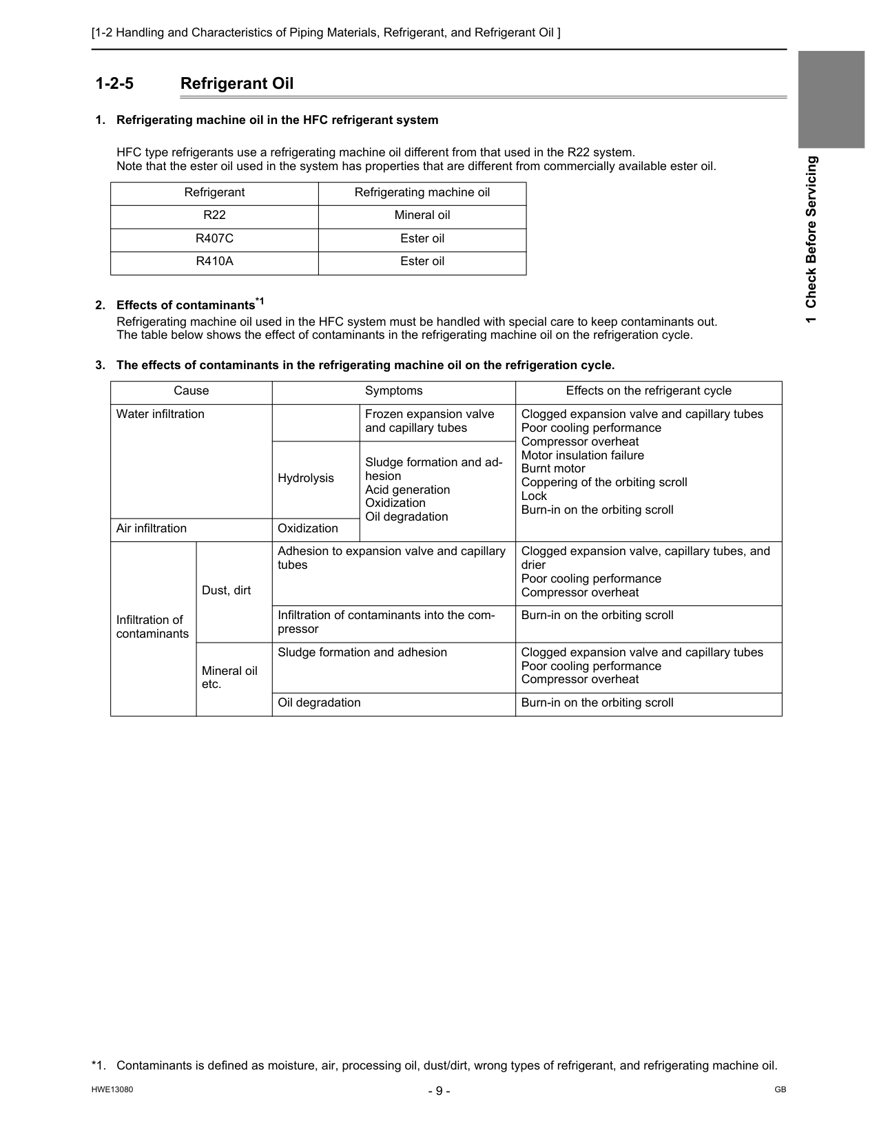
[1-2 Handling and Characteristics of Piping Materials, Refrigerant, and Refrigerant Oil ]
Hwe13080
Gb
1 Check Before Servicing 1-2-5 Refrigerant OilR22
Mineral oilR407C
Ester oilR410A
Ester oil *1. Contaminants is defined as moisture, air, processing oil, dust/dirt, wrong types of refrigerant, and refrigerating machine oil. Cause Symptoms Effects on the refrigerant cycle Water infiltration Frozen expansion valve and capillary tubes Clogged expansion valve and capillary tubes Poor cooling performance Compressor overheat Motor insulation failure Burnt motor Coppering of the orbiting scroll Lock Burn-in on the orbiting scroll Hydrolysis Sludge formation and ad- hesion Acid generation Oxidization Oil degradation Air infiltration Oxidization Infiltration of contaminants Dust, dirt Adhesion to expansion valve and capillary tubes Clogged expansion valve, capillary tubes, and drier Poor cooling performance Compressor overheat Infiltration of contaminants into the com- pressor Burn-in on the orbiting scroll Mineral oil etc. Sludge formation and adhesion Clogged expansion valve and capillary tubes Poor cooling performance Compressor overheat Oil degradation Burn-in on the orbiting scroll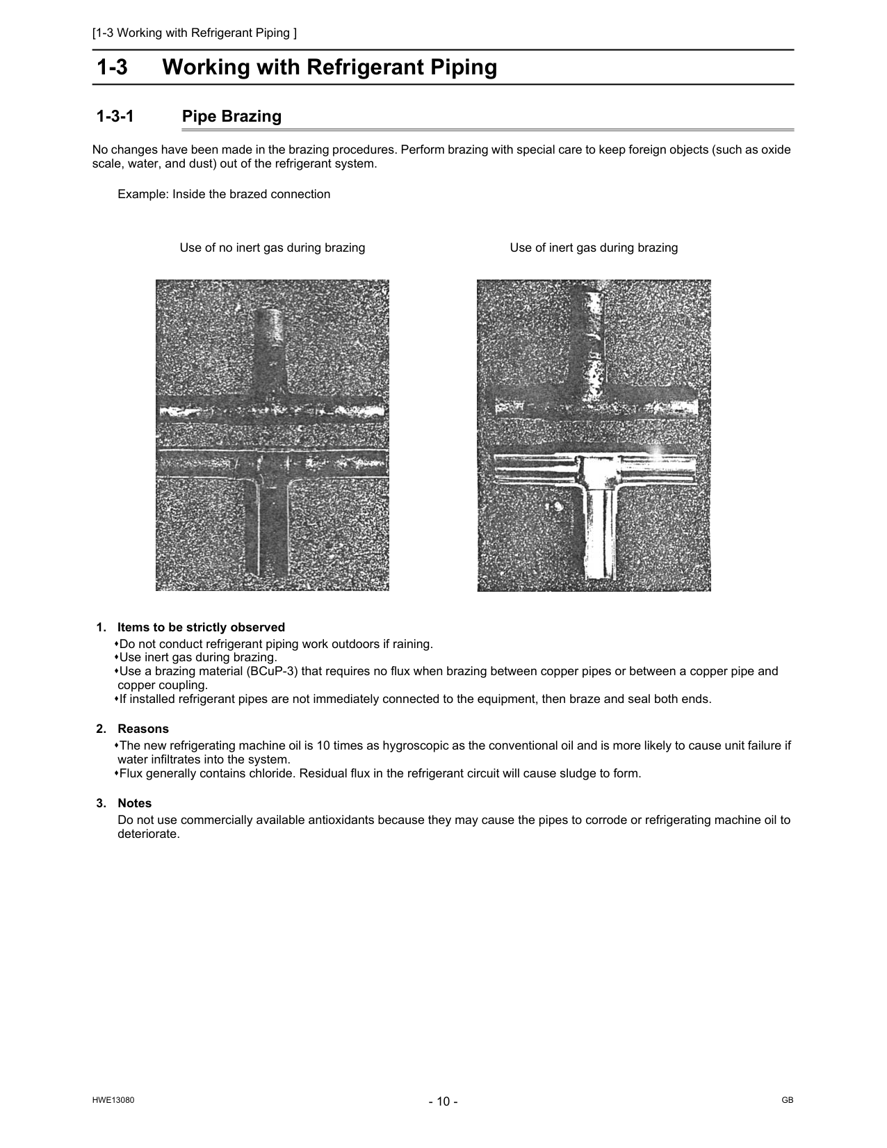
[1-3 Working with Refrigerant Piping ]
Hwe13080
Gb
1-3 Working with Refrigerant Piping 1-3-1 Pipe Brazing No changes have been made in the brazing procedures. Perform brazing with special care to keep foreign objects (such as oxide scale, water, and dust) out of the refrigerant system. Example: Inside the brazed connection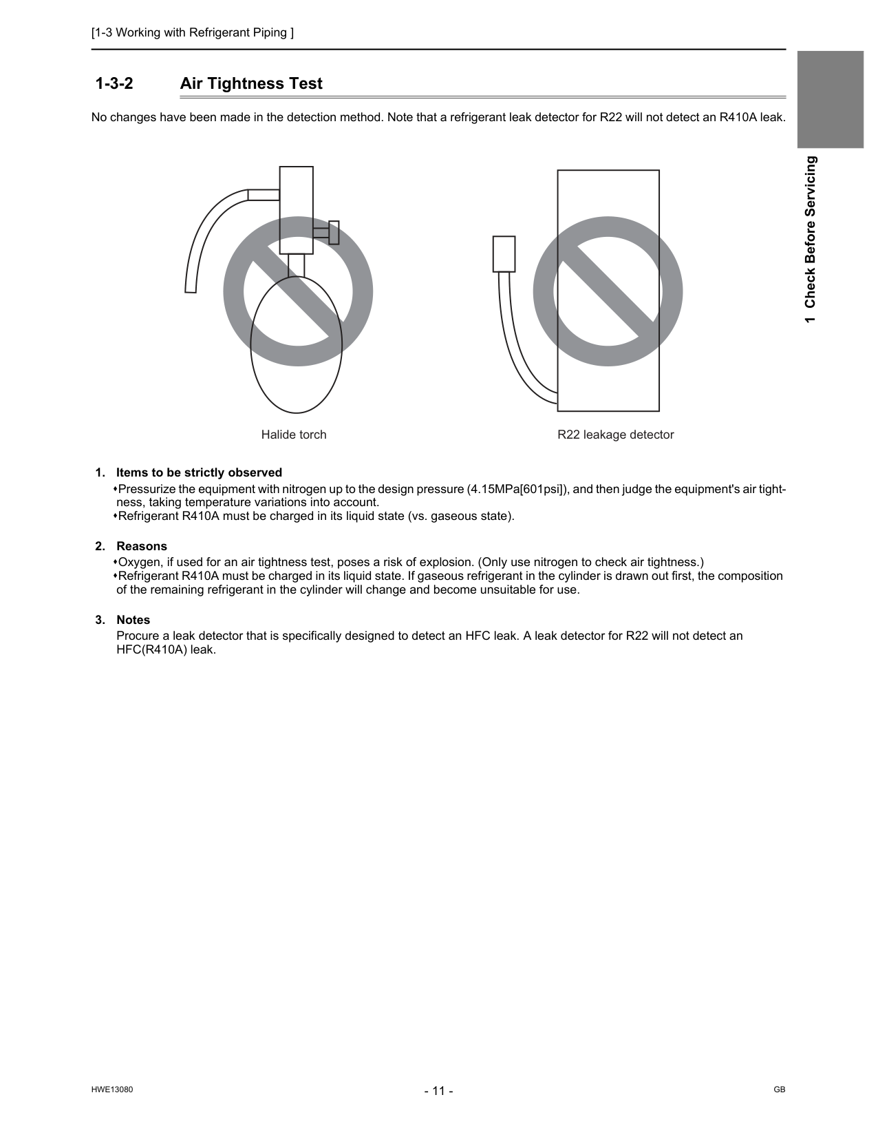
[1-3 Working with Refrigerant Piping ]
Hwe13080
Gb
1 Check Before Servicing 1-3-2 Air Tightness Test No changes have been made in the detection method. Note that a refrigerant leak detector for R22 will not detect an R410A leak.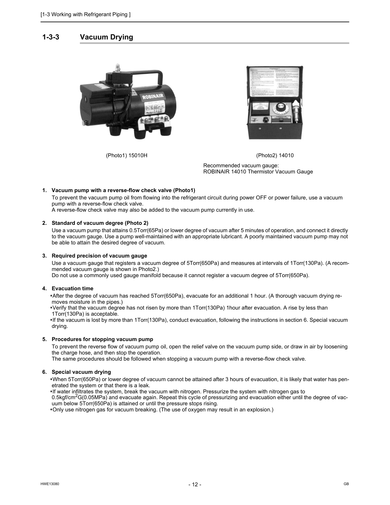
[1-3 Working with Refrigerant Piping ]
Hwe13080
Gb
1-3-3 Vacuum Drying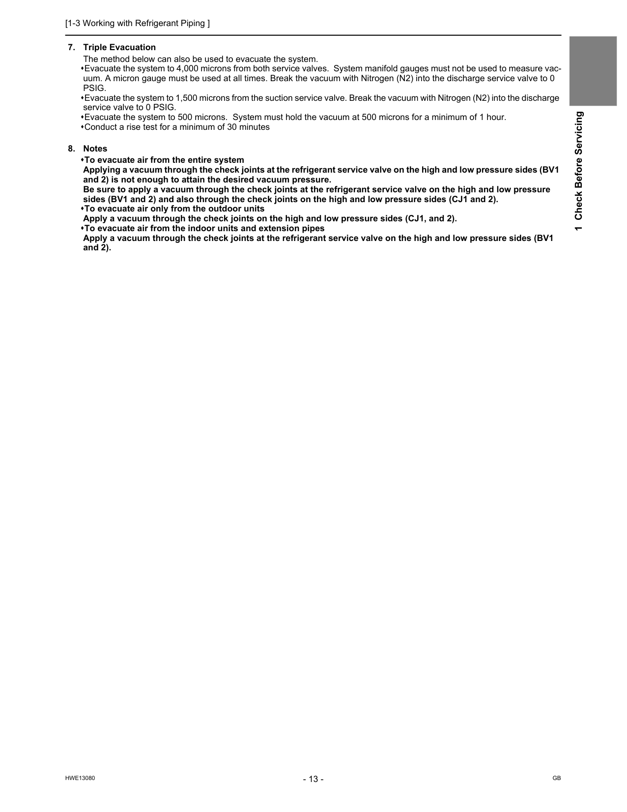
[1-3 Working with Refrigerant Piping ]
Hwe13080
Gb
1 Check Before ServicingPsig.
Evacuate the system to 1,500 microns from the suction service valve. Break the vacuum with Nitrogen (N2) into the discharge service valve to 0 PSIG. Evacuate the system to 500 microns. System must hold the vacuum at 500 microns for a minimum of 1 hour. Conduct a rise test for a minimum of 30 minutes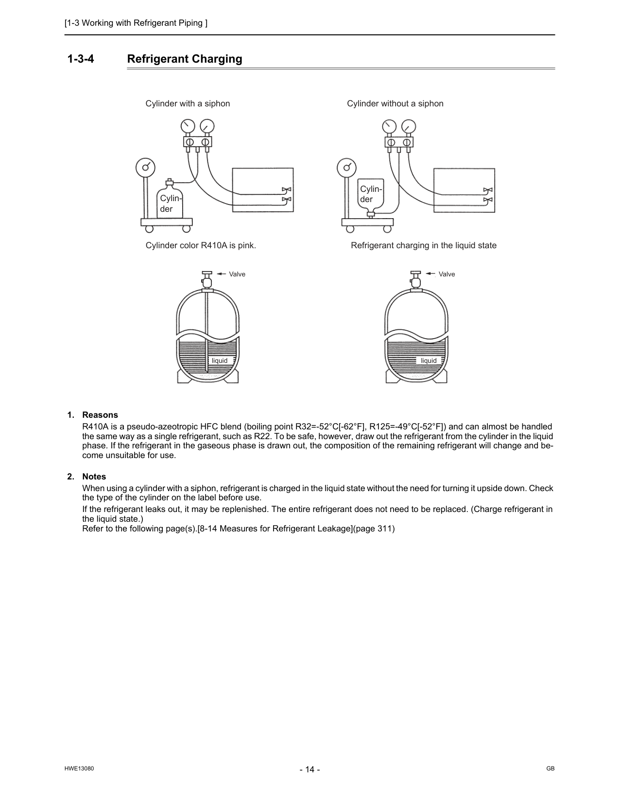
[1-3 Working with Refrigerant Piping ]
Hwe13080
Gb
1-3-4 Refrigerant Charging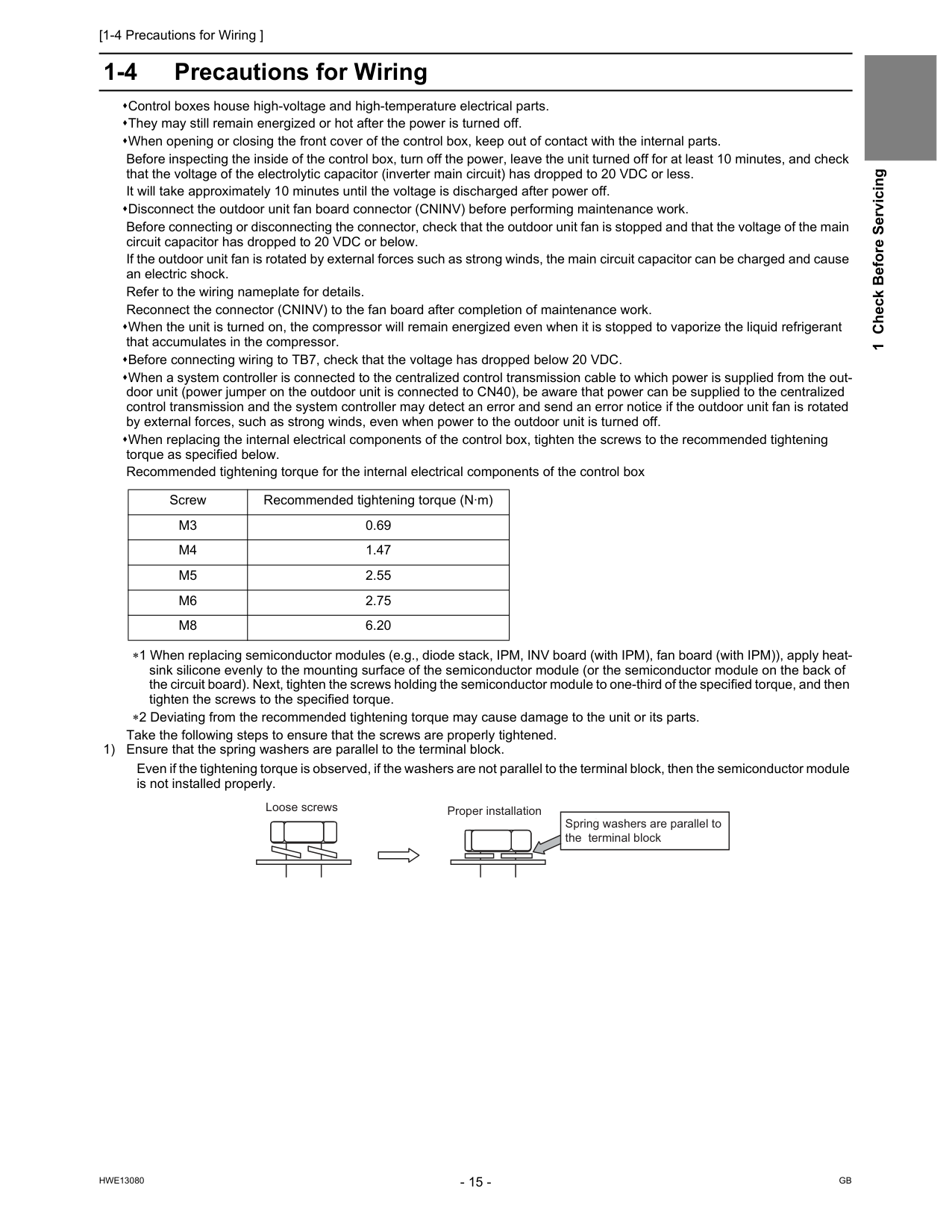
[1-4 Precautions for Wiring ]
Hwe13080
Gb
1 Check Before Servicing 1-4 Precautions for Wiring Control boxes house high-voltage and high-temperature electrical parts. They may still remain energized or hot after the power is turned off. When opening or closing the front cover of the control box, keep out of contact with the internal parts. Before inspecting the inside of the control box, turn off the power, leave the unit turned off for at least 10 minutes, and check that the voltage of the electrolytic capacitor (inverter main circuit) has dropped to 20 VDC or less. It will take approximately 10 minutes until the voltage is discharged after power off. Disconnect the outdoor unit fan board connector (CNINV) before performing maintenance work. Before connecting or disconnecting the connector, check that the outdoor unit fan is stopped and that the voltage of the main circuit capacitor has dropped to 20 VDC or below. If the outdoor unit fan is rotated by external forces such as strong winds, the main circuit capacitor can be charged and cause an electric shock. Refer to the wiring nameplate for details. Reconnect the connector (CNINV) to the fan board after completion of maintenance work. When the unit is turned on, the compressor will remain energized even when it is stopped to vaporize the liquid refrigerant that accumulates in the compressor. Before connecting wiring to TB7, check that the voltage has dropped below 20 VDC. When a system controller is connected to the centralized control transmission cable to which power is supplied from the out- door unit (power jumper on the outdoor unit is connected to CN40), be aware that power can be supplied to the centralized control transmission and the system controller may detect an error and send an error notice if the outdoor unit fan is rotated by external forces, such as strong winds, even when power to the outdoor unit is turned off. When replacing the internal electrical components of the control box, tighten the screws to the recommended tightening torque as specified below. Recommended tightening torque for the internal electrical components of the control box ∗1 When replacing semiconductor modules (e.g., diode stack, IPM, INV board (with IPM), fan board (with IPM)), apply heat- sink silicone evenly to the mounting surface of the semiconductor module (or the semiconductor module on the back of the circuit board). Next, tighten the screws holding the semiconductor module to one-third of the specified torque, and then tighten the screws to the specified torque. ∗2 Deviating from the recommended tightening torque may cause damage to the unit or its parts. Take the following steps to ensure that the screws are properly tightened. 1) Ensure that the spring washers are parallel to the terminal block. Even if the tightening torque is observed, if the washers are not parallel to the terminal block, then the semiconductor module is not installed properly. Screw Recommended tightening torque (N·m)M3
0.69M4
1.47M5
2.55M6
2.75M8
6.20 Proper installation Loose screws Spring washers are parallel to the terminal block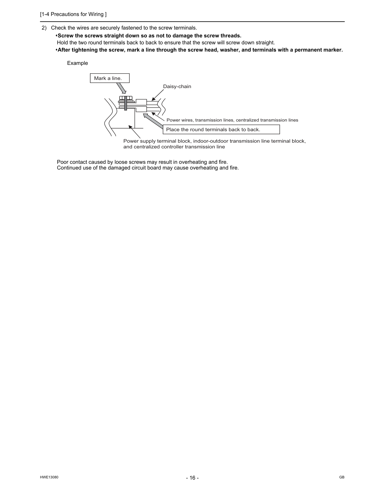
[1-4 Precautions for Wiring ]
Hwe13080
Gb
2) Check the wires are securely fastened to the screw terminals. Screw the screws straight down so as not to damage the screw threads. Hold the two round terminals back to back to ensure that the screw will screw down straight. After tightening the screw, mark a line through the screw head, washer, and terminals with a permanent marker. Example Poor contact caused by loose screws may result in overheating and fire. Continued use of the damaged circuit board may cause overheating and fire. Daisy-chain Power supply terminal block, indoor-outdoor transmission line terminal block, and centralized controller transmission line Mark a line. Place the round terminals back to back. Power wires, transmission lines, centralized transmission lines
Hwe13080
Gb
Chapter 2 Restrictions 2-1 System Configurations....................................................................................................................... 19 2-2 Types and Maximum Allowable Length of Cables........................................................................... 20 2-3 Switch Settings ................................................................................................................................... 21 2-4 M-NET Address Settings.................................................................................................................... 22 2-4-1 Address Settings List ............................................................................................................................ 22 2-4-2 Outdoor Unit Power Jumper Connector Connection............................................................................. 24 2-4-3 Outdoor Unit Centralized Controller Switch Setting.............................................................................. 24 2-4-4 Room Temperature Detection Position Selection................................................................................. 24 2-4-5 Start/Stop Control of Indoor Units......................................................................................................... 25 2-4-6 Miscellaneous Settings ......................................................................................................................... 25 2-4-7 Various Control Methods Using the Signal Input/Output Connector on Outdoor Unit .......................... 26 2-5 Demand Control Overview................................................................................................................. 29 2-6 System Connection Example............................................................................................................. 30 2-7 Example System with an MA Remote Controller ............................................................................. 32 2-7-1 Single Refrigerant System (Automatic Indoor/Outdoor Address Startup)............................................. 32 2-7-2 Single Refrigerant System with Two or More LOSSNAY Units ............................................................ 34 2-7-3 Grouped Operation of Units in Separate Refrigerant Circuits............................................................... 36 2-7-4 System with a Connection of System Controller to Centralized Control Transmission Line................. 38 2-7-5 System with a Connection of System Controller to Indoor-Outdoor Transmission Line ....................... 40 2-7-6 System with Multiple BC Controllers..................................................................................................... 42 2-8 Example System with an ME Remote Controller ............................................................................. 46 2-8-1 System with a Connection of System Controller to Centralized Control Transmission Line................. 46 2-9 Example System with an MA and an ME Remote Controller .......................................................... 48 2-9-1 System with a Connection of System Controller to Centralized Control Transmission Line................. 48 2-10 Restrictions on Refrigerant Pipes..................................................................................................... 51 2-10-1 Restrictions on Refrigerant Pipe Length ............................................................................................... 51 2-10-2 Restrictions on Refrigerant Pipe Size ................................................................................................... 57 2-10-3 BC Controller Connection Method ........................................................................................................ 58
Hwe13080
Gb
[2-1 System Configurations ]
Hwe13080
Gb
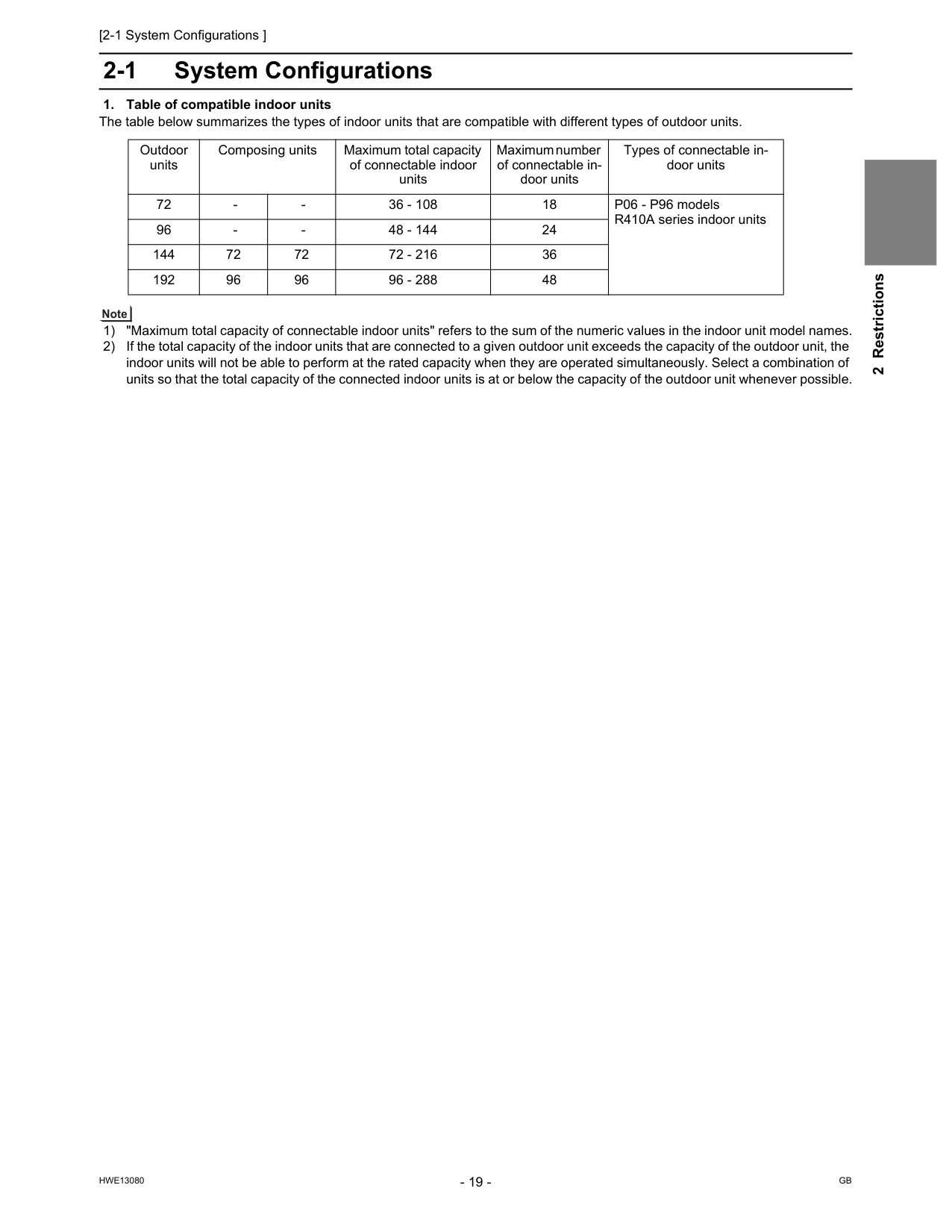
2 Restrictions 2 Restrictions2-1 System Configurations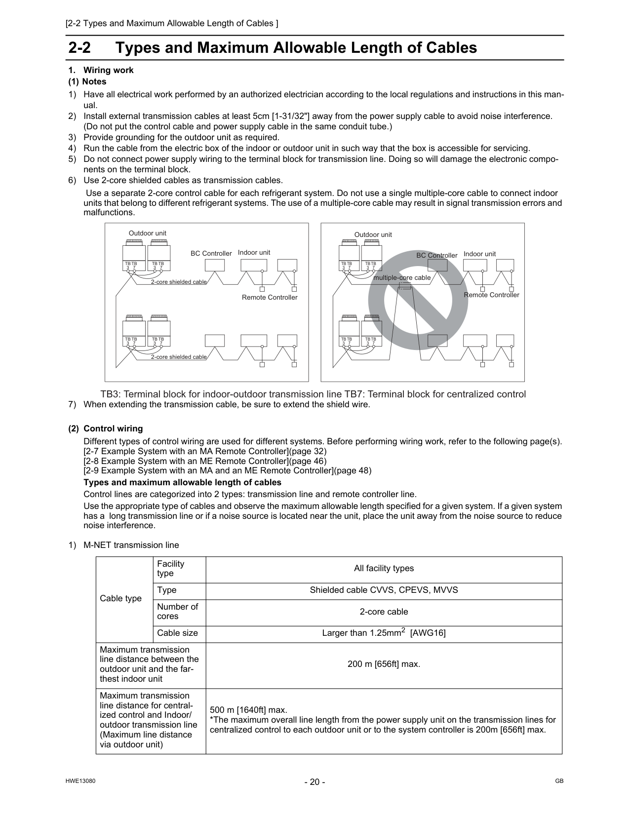
[2-2 Types and Maximum Allowable Length of Cables ]
Hwe13080
Gb
2-2 Types and Maximum Allowable Length of CablesTb
3Tb
7Tb
3Tb
7Tb
3Tb
7Tb
3Tb
7Tb
3Tb
7Tb
3Tb
7Tb
3Tb
7Tb
3Tb
7 TB3: Terminal block for indoor-outdoor transmission line TB7: Terminal block for centralized control multiple-core cable BC Controller Indoor unit Remote Controller Remote Controller 2-core shielded cable 2-core shielded cable Outdoor unit BC Controller Indoor unit Outdoor unit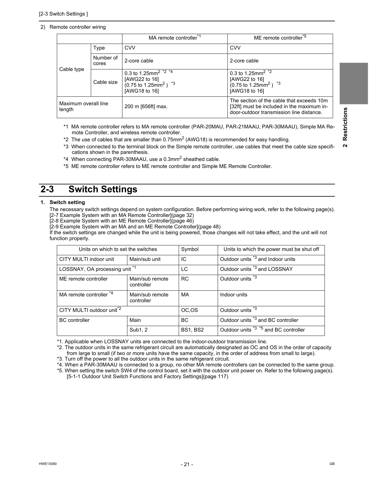
[2-3 Switch Settings ]
Hwe13080
Gb
2 Restrictions 2) Remote controller wiring *1 MA remote controller refers to MA remote controller (PAR-20MAU, PAR-21MAAU, PAR-30MAAU), Simple MA Re- mote Controller, and wireless remote controller. *2 The use of cables that are smaller than 0.75mm2 (AWG18) is recommended for easy handling. *3 When connected to the terminal block on the Simple remote controller, use cables that meet the cable size specifi- cations shown in the parenthesis. *4 When connecting PAR-30MAAU, use a 0.3mm2 sheathed cable. *5 ME remote controller refers to ME remote controller and Simple ME Remote Controller. 2-3 Switch SettingsCvv
Cvv
Number of cores 2-core cable 2-core cable Cable size 0.3 to 1.25mm2 *2 *4 [AWG22 to 16] (0.75 to 1.25mm2 ) *3 [AWG18 to 16] 0.3 to 1.25mm2 *2 [AWG22 to 16] (0.75 to 1.25mm2 ) *3 [AWG18 to 16] Maximum overall line length 200 m [656ft] max. The section of the cable that exceeds 10m [32ft] must be included in the maximum in- door-outdoor transmission line distance. Units on which to set the switches Symbol Units to which the power must be shut off CITY MULTI indoor unit Main/sub unitIc
Outdoor units *3 and Indoor units LOSSNAY, OA processing unit *1Lc
Outdoor units *3 and LOSSNAY ME remote controller Main/sub remote controllerRc
Outdoor units *3 MA remote controller *4 Main/sub remote controllerMa
Indoor units CITY MULTI outdoor unit*2Oc,Os
Outdoor units *3 BC controller MainBc
Outdoor units *3 and BC controller Sub1, 2Bs1, Bs2
Outdoor units *3 *5 and BC controller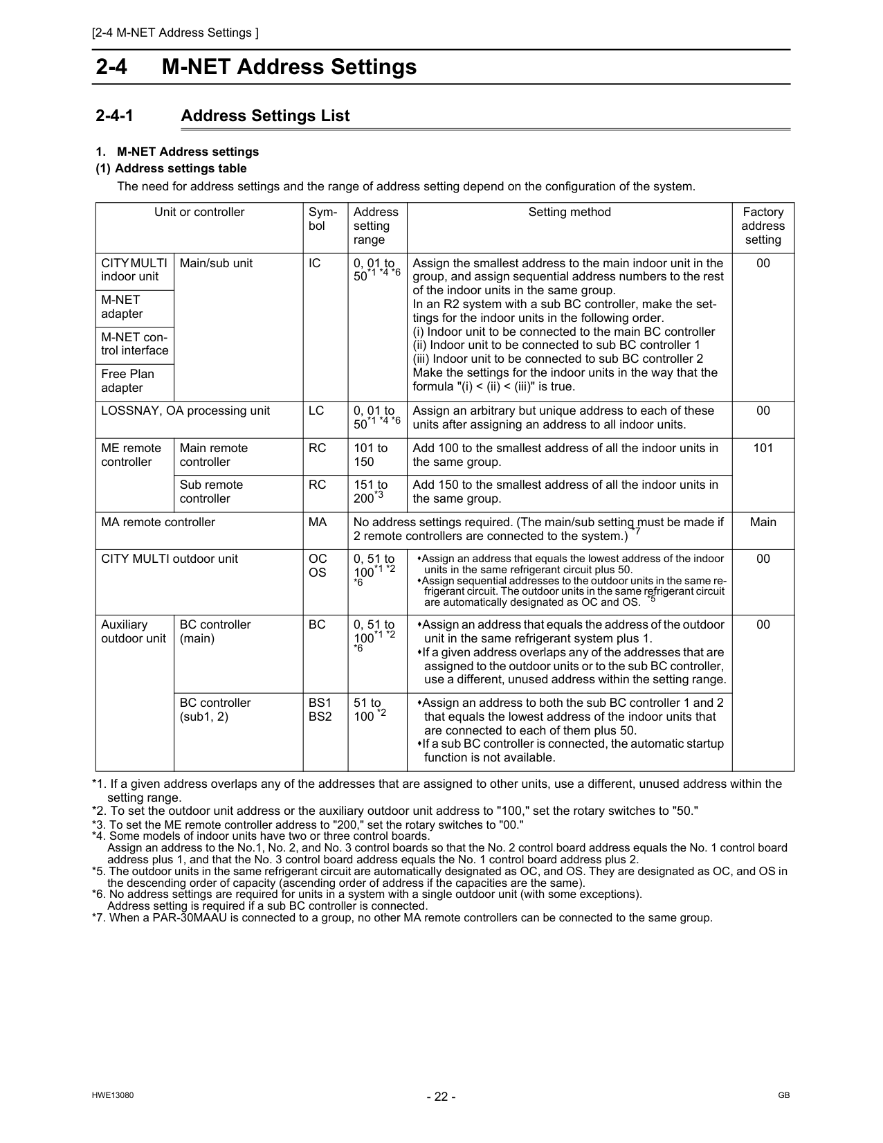
[2-4 M-NET Address Settings ]
Hwe13080
Gb
2-4 M-NET Address Settings 2-4-1 Address Settings ListCity Multi
indoor unit Main/sub unitIc
0, 01 to 50*1 *4 *6 Assign the smallest address to the main indoor unit in the group, and assign sequential address numbers to the rest of the indoor units in the same group. In an R2 system with a sub BC controller, make the set- tings for the indoor units in the following order. (i) Indoor unit to be connected to the main BC controller (ii) Indoor unit to be connected to sub BC controller 1 (iii) Indoor unit to be connected to sub BC controller 2 Make the settings for the indoor units in the way that the formula "(i) < (ii) < (iii)" is true. 00M-Net
adapter M-NET con- trol interface Free Plan adapter LOSSNAY, OA processing unitLc
0, 01 to 50*1 *4 *6 Assign an arbitrary but unique address to each of these units after assigning an address to all indoor units. 00 ME remote controller Main remote controllerRc
101 to 150 Add 100 to the smallest address of all the indoor units in the same group. 101 Sub remote controllerRc
151 to 200*3 Add 150 to the smallest address of all the indoor units in the same group. MA remote controllerMa
No address settings required. (The main/sub setting must be made if 2 remote controllers are connected to the system.) *7 Main CITY MULTI outdoor unitOc
Os
0, 51 to 100*1 *2 *6 Assign an address that equals the lowest address of the indoor units in the same refrigerant circuit plus 50. Assign sequential addresses to the outdoor units in the same re- frigerant circuit. The outdoor units in the same refrigerant circuit are automatically designated as OC and OS. *5 00 Auxiliary outdoor unit BC controller (main)Bc
0, 51 to 100*1 *2 *6 Assign an address that equals the address of the outdoor unit in the same refrigerant system plus 1. If a given address overlaps any of the addresses that are assigned to the outdoor units or to the sub BC controller, use a different, unused address within the setting range. 00 BC controller (sub1, 2)Bs1
Bs2
51 to 100 *2 Assign an address to both the sub BC controller 1 and 2 that equals the lowest address of the indoor units that are connected to each of them plus 50. If a sub BC controller is connected, the automatic startup function is not available.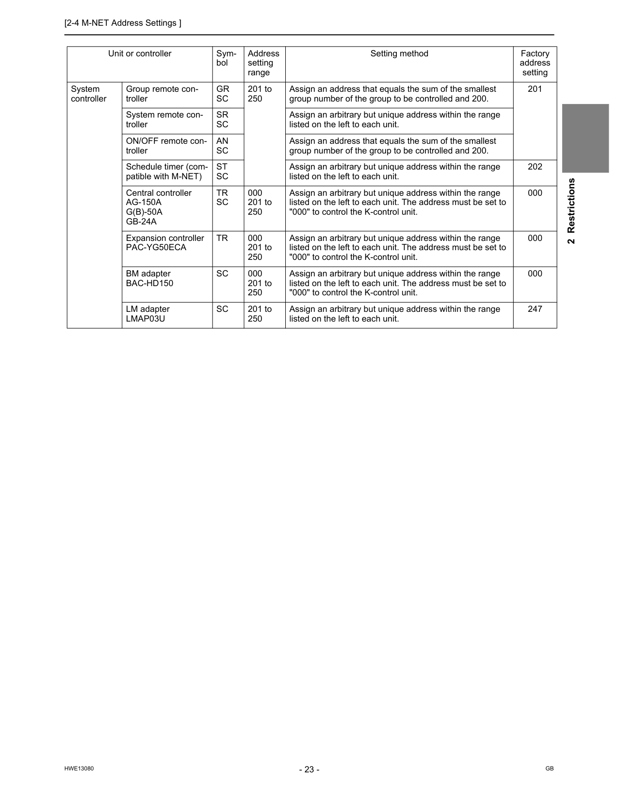
[2-4 M-NET Address Settings ]
Hwe13080
Gb
2 Restrictions Unit or controller Sym- bol Address setting range Setting method Factory address setting System controller Group remote con- trollerGr
Sc
201 to 250 Assign an address that equals the sum of the smallest group number of the group to be controlled and 200. 201 System remote con- trollerSr
Sc
Assign an arbitrary but unique address within the range listed on the left to each unit. ON/OFF remote con- trollerAn
Sc
Assign an address that equals the sum of the smallest group number of the group to be controlled and 200. Schedule timer (com- patible with M-NET)St
Sc
Assign an arbitrary but unique address within the range listed on the left to each unit. 202 Central controllerAg-150A
G(B)-50A
Gb-24A
Tr
Sc
000 201 to 250 Assign an arbitrary but unique address within the range listed on the left to each unit. The address must be set to "000" to control the K-control unit. 000 Expansion controllerPac-Yg50Eca
Tr
000 201 to 250 Assign an arbitrary but unique address within the range listed on the left to each unit. The address must be set to "000" to control the K-control unit. 000 BM adapterBac-Hd150
Sc
000 201 to 250 Assign an arbitrary but unique address within the range listed on the left to each unit. The address must be set to "000" to control the K-control unit. 000 LM adapterLmap03U
Sc
201 to 250 Assign an arbitrary but unique address within the range listed on the left to each unit. 247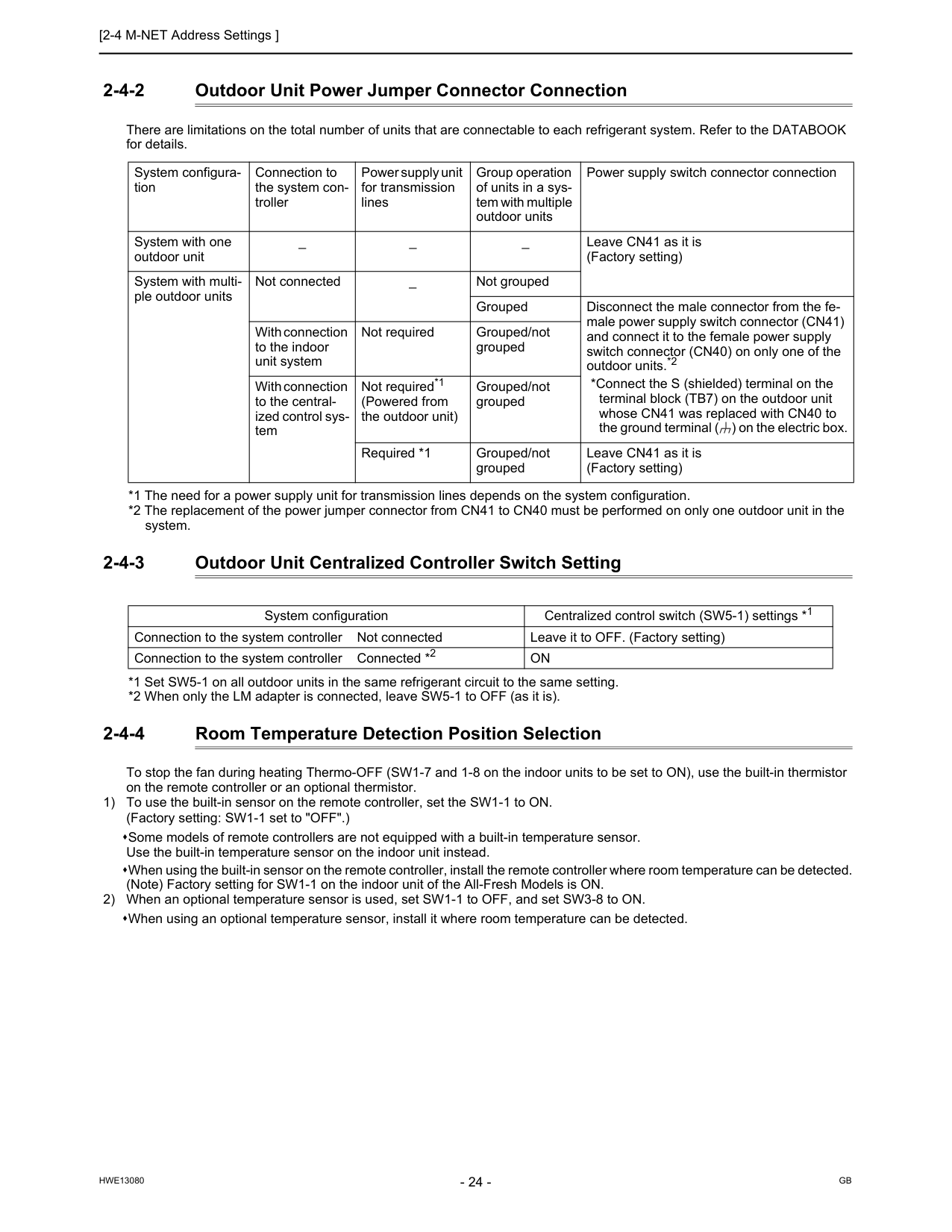
[2-4 M-NET Address Settings ]
Hwe13080
Gb
2-4-2 Outdoor Unit Power Jumper Connector Connection There are limitations on the total number of units that are connectable to each refrigerant system. Refer to the DATABOOK for details. *1 The need for a power supply unit for transmission lines depends on the system configuration. *2 The replacement of the power jumper connector from CN41 to CN40 must be performed on only one outdoor unit in the system. 2-4-3 Outdoor Unit Centralized Controller Switch Setting *1 Set SW5-1 on all outdoor units in the same refrigerant circuit to the same setting. *2 When only the LM adapter is connected, leave SW5-1 to OFF (as it is). 2-4-4 Room Temperature Detection Position Selection To stop the fan during heating Thermo-OFF (SW1-7 and 1-8 on the indoor units to be set to ON), use the built-in thermistor on the remote controller or an optional thermistor. 1) To use the built-in sensor on the remote controller, set the SW1-1 to ON. (Factory setting: SW1-1 set to "OFF".) Some models of remote controllers are not equipped with a built-in temperature sensor. Use the built-in temperature sensor on the indoor unit instead. When using the built-in sensor on the remote controller, install the remote controller where room temperature can be detected. (Note) Factory setting for SW1-1 on the indoor unit of the All-Fresh Models is ON. 2) When an optional temperature sensor is used, set SW1-1 to OFF, and set SW3-8 to ON. When using an optional temperature sensor, install it where room temperature can be detected. System configura- tion Connection to the system con- troller Power supply unit for transmission lines Group operation of units in a sys- tem with multiple outdoor units Power supply switch connector connection System with one outdoor unit _ _ _ Leave CN41 as it is (Factory setting) System with multi- ple outdoor units Not connected _ Not grouped Grouped Disconnect the male connector from the fe- male power supply switch connector (CN41) and connect it to the female power supply switch connector (CN40) on only one of the outdoor units.*2 *Connect the S (shielded) terminal on the terminal block (TB7) on the outdoor unit whose CN41 was replaced with CN40 to the ground terminal ( ) on the electric box. With connection to the indoor unit system Not required Grouped/not grouped With connection to the central- ized control sys- tem Not required*1 (Powered from the outdoor unit) Grouped/not grouped Required *1 Grouped/not grouped Leave CN41 as it is (Factory setting) System configuration Centralized control switch (SW5-1) settings *1 Connection to the system controller Not connected Leave it to OFF. (Factory setting) Connection to the system controller Connected *2On
[2-4 M-NET Address Settings ]
Hwe13080
Gb
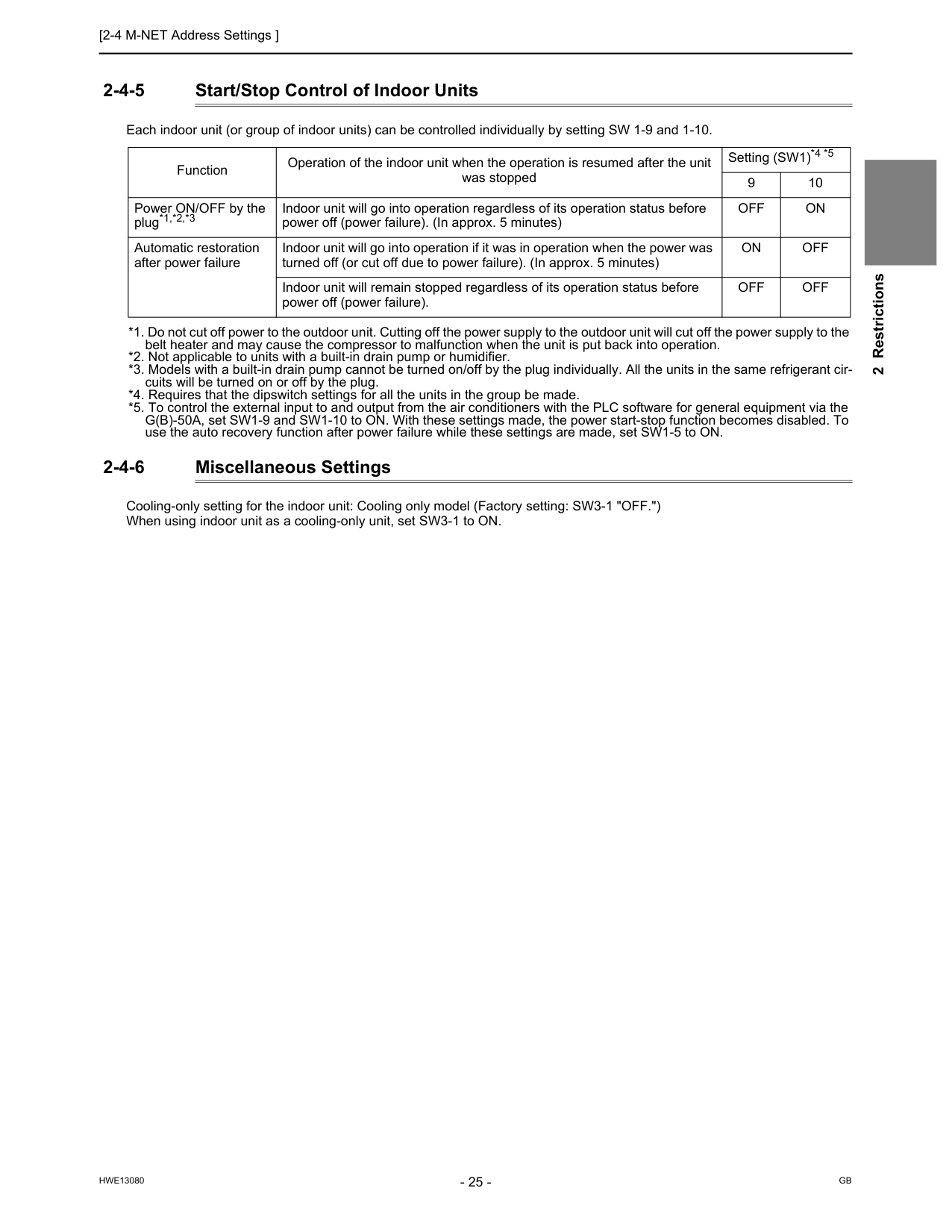
2 Restrictions 2-4-5 Start/Stop Control of Indoor Units Each indoor unit (or group of indoor units) can be controlled individually by setting SW 1-9 and 1-10. *1. Do not cut off power to the outdoor unit. Cutting off the power supply to the outdoor unit will cut off the power supply to the belt heater and may cause the compressor to malfunction when the unit is put back into operation. *2. Not applicable to units with a built-in drain pump or humidifier. *3. Models with a built-in drain pump cannot be turned on/off by the plug individually. All the units in the same refrigerant cir- cuits will be turned on or off by the plug. *4. Requires that the dipswitch settings for all the units in the group be made. *5. To control the external input to and output from the air conditioners with the PLC software for general equipment via the G(B)-50A, set SW1-9 and SW1-10 to ON. With these settings made, the power start-stop function becomes disabled. To use the auto recovery function after power failure while these settings are made, set SW1-5 to ON. 2-4-6 Miscellaneous Settings Cooling-only setting for the indoor unit: Cooling only model (Factory setting: SW3-1 "OFF.") When using indoor unit as a cooling-only unit, set SW3-1 to ON. Function Operation of the indoor unit when the operation is resumed after the unit was stopped Setting (SW1)*4 *5 9 10 Power ON/OFF by the plug*1,*2,*3 Indoor unit will go into operation regardless of its operation status before power off (power failure). (In approx. 5 minutes)Off
On
Automatic restoration after power failure Indoor unit will go into operation if it was in operation when the power was turned off (or cut off due to power failure). (In approx. 5 minutes)On
Off
Indoor unit will remain stopped regardless of its operation status before power off (power failure).Off
Off
[2-4 M-NET Address Settings ]
Hwe13080
Gb
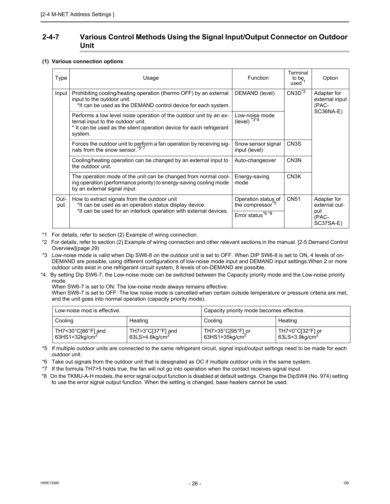
2-4-7 Various Control Methods Using the Signal Input/Output Connector on Outdoor Unit (1) Various connection options *1 For details, refer to section (2) Example of wiring connection. *2 For details, refer to section (2) Example of wiring connection and other relevant sections in the manual. [2-5 Demand Control Overview](page 29) *3 Low-noise mode is valid when Dip SW6-8 on the outdoor unit is set to OFF. When DIP SW6-8 is set to ON, 4 levels of on- DEMAND are possible, using different configurations of low-noise mode input and DEMAND input settings.When 2 or more outdoor units exist in one refrigerant circuit system, 8 levels of on-DEMAND are possible. *4. By setting Dip SW6-7, the Low-noise mode can be switched between the Capacity priority mode and the Low-noise priority mode. When SW6-7 is set to ON: The low-noise mode always remains effective. When SW6-7 is set to OFF: The low noise mode is cancelled when certain outside temperature or pressure criteria are met, and the unit goes into normal operation (capacity priority mode). *5 If multiple outdoor units are connected to the same refrigerant circuit, signal input/output settings need to be made for each outdoor unit. *6 Take out signals from the outdoor unit that is designated as OC if multiple outdoor units in the same system. *7 If the formula TH7>5 holds true, the fan will not go into operation when the contact receives signal input. *8 On the TKMU-A-H models, the error signal output function is disabled at default settings. Change the DipSW4 (No. 974) setting to use the error signal output function. When the setting is changed, base heaters cannot be used. Type Usage Function Terminal to be used*1 Option Input Prohibiting cooling/heating operation (thermo OFF) by an external input to the outdoor unit. *It can be used as the DEMAND control device for each system. DEMAND (level)Cn3D*2
Adapter for external input(Pac-
Sc36Na-E)
Performs a low level noise operation of the outdoor unit by an ex- ternal input to the outdoor unit.Cn3S
Cooling/heating operation can be changed by an external input to the outdoor unit. Auto-changeoverCn3N
The operation mode of the unit can be changed from normal cool- ing operation (performance priority) to energy-saving cooling mode by an external signal input. Energy-saving modeCn3K
Out- put How to extract signals from the outdoor unit *It can be used as an operation status display device. *It can be used for an interlock operation with external devices. Operation status of the compressor*5Cn51
Adapter for external out- put(Pac-
Sc37Sa-E)
Error status*6 *8 Low-noise mod is effective. Capacity priority mode becomes effective. Cooling Heating Cooling Heating TH7<30°C[86°F] and 63HS1<32kg/cm2 TH7>3°C[37°F] and 63LS>4.6kg/cm2 TH7>35°C[95°F] or 63HS1>35kg/cm2 TH7<0°C[32°F] or 63LS<3.9kg/cm2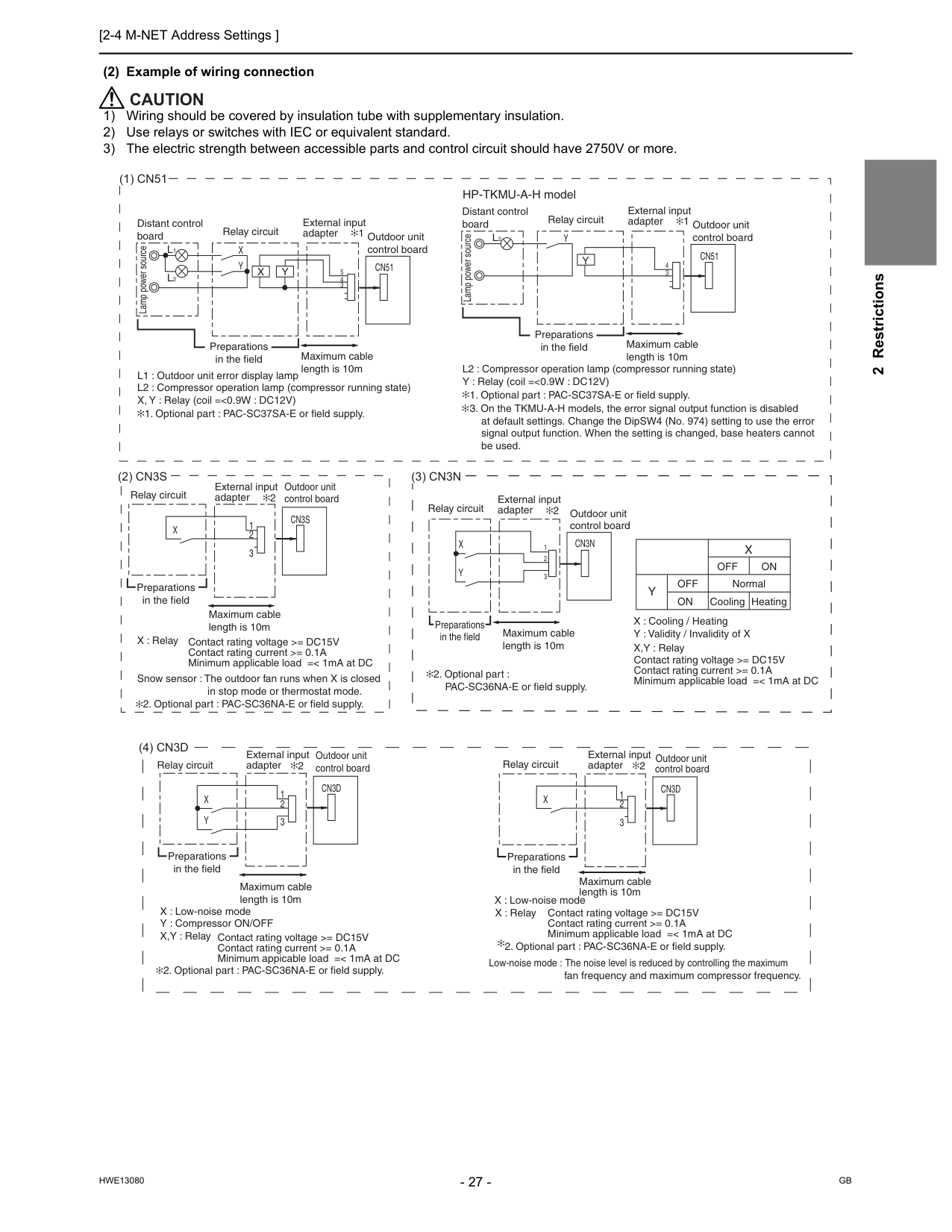
[2-4 M-NET Address Settings ]
Hwe13080
Gb
2 Restrictions (2) Example of wiring connectionCaution
1) Wiring should be covered by insulation tube with supplementary insulation. 2) Use relays or switches with IEC or equivalent standard. 3) The electric strength between accessible parts and control circuit should have 2750V or more.(1) Cn51
(2) Cn3S
Cn51
X
Y
L1
L2
e cru o s re w o p p m aL
Distant control board Relay circuit 1 Outdoor unit control board Preparations in the field Maximum cable length is 10m 5 4 3X
Y
L1 : Outdoor unit error display lamp L2 : Compressor operation lamp (compressor running state) X, Y : Relay (coil =<0.9W : DC12V)X
Cn3S
Preparations in the field Maximum cable length is 10m External input adapterCn51
Y
L2
e cru o s re w o p p m aL
Distant control board Relay circuit 1 Outdoor unit control board Preparations in the field Maximum cable length is 10m 4 3Y
L2 : Compressor operation lamp (compressor running state) Y : Relay (coil =<0.9W : DC12V)(3) Cn3N
Off
CoolingOn
Heating NormalY
Off
On
X
Contact rating voltage >= DC15V Contact rating current >= 0.1A Minimum applicable load =< 1mA at DC X : Cooling / Heating Y : Validity / Invalidity of X X,Y : RelayCn3N
X
Y
Relay circuit Outdoor unit control board Maximum cable length is 10m 1 2 3 2 External input adapter 2 External input adapter HP-TKMU-A-H model(4) Cn3D
Y
X
Cn3D
Preparations in the field Maximum cable length is 10m External input adapter 2 Outdoor unit control board 3 2 1 Relay circuitX
Cn3D
Preparations in the field Maximum cable length is 10m Outdoor unit control board 2 3 1 X : Relay fan frequency and maximum compressor frequency. Contact rating voltage >= DC15V Contact rating current >= 0.1A Minimum applicable load =< 1mA at DC Low-noise mode : The noise level is reduced by controlling the maximum Relay circuit External input adapter 2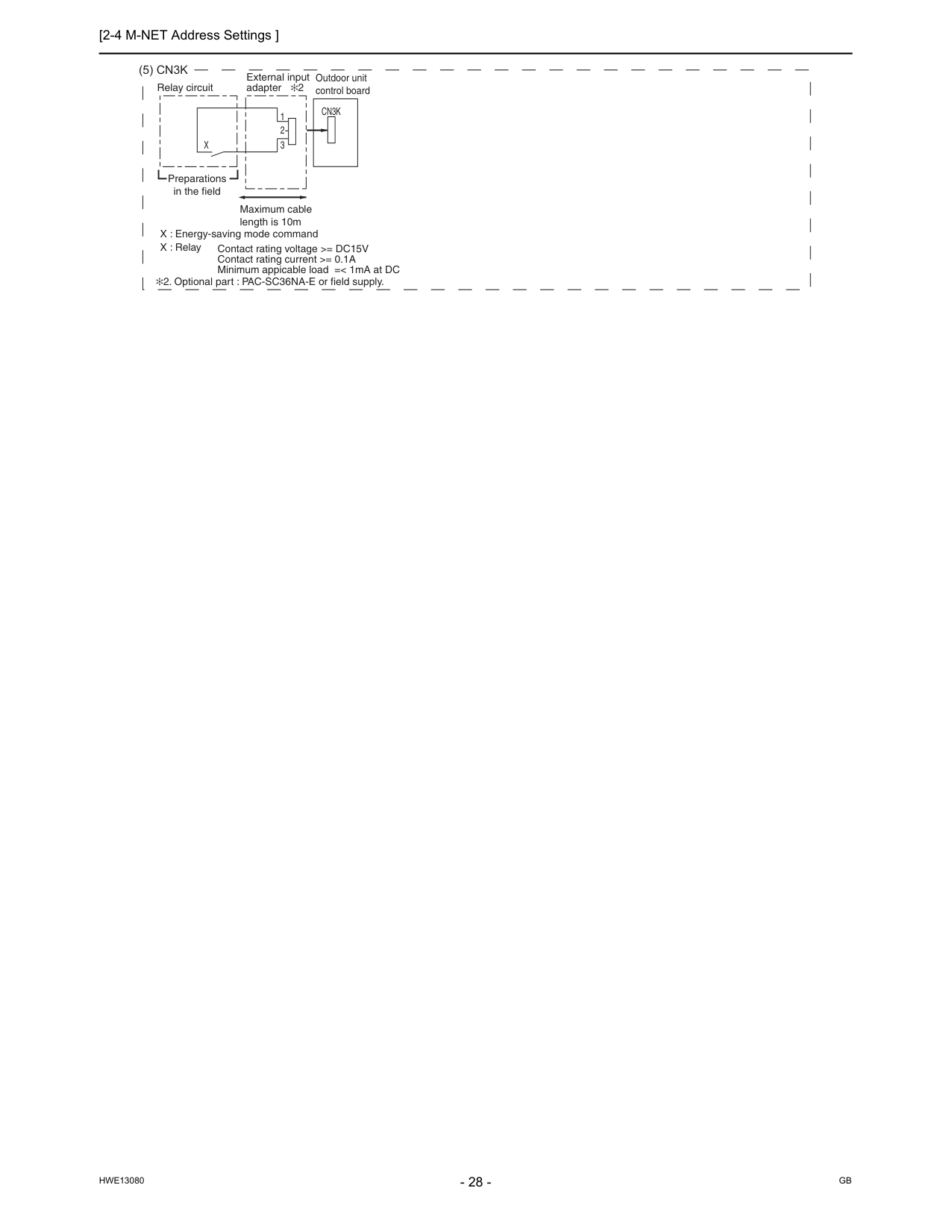
[2-4 M-NET Address Settings ]
Hwe13080
Gb
(5) Cn3K
X
Cn3K
Preparations in the field Maximum cable length is 10m Outdoor unit control board 3 2 1 Relay circuit External input adapter 2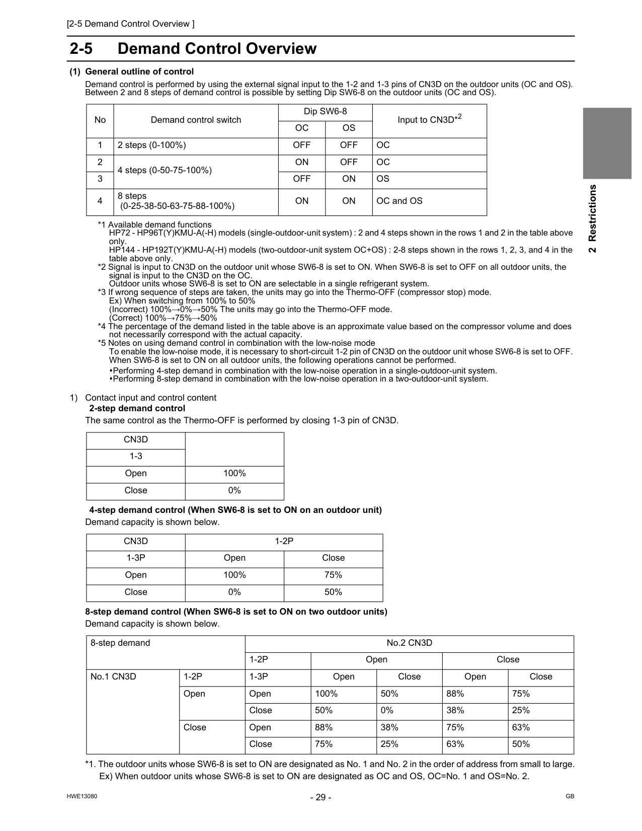
[2-5 Demand Control Overview ]
Hwe13080
Gb
2 Restrictions 2-5 Demand Control Overview (1) General outline of control Demand control is performed by using the external signal input to the 1-2 and 1-3 pins of CN3D on the outdoor units (OC and OS). Between 2 and 8 steps of demand control is possible by setting Dip SW6-8 on the outdoor units (OC and OS). *1 Available demand functions HP72 - HP96T(Y)KMU-A(-H) models (single-outdoor-unit system) : 2 and 4 steps shown in the rows 1 and 2 in the table above only. HP144 - HP192T(Y)KMU-A(-H) models (two-outdoor-unit system OC+OS) : 2-8 steps shown in the rows 1, 2, 3, and 4 in the table above only. *2 Signal is input to CN3D on the outdoor unit whose SW6-8 is set to ON. When SW6-8 is set to OFF on all outdoor units, the signal is input to the CN3D on the OC. Outdoor units whose SW6-8 is set to ON are selectable in a single refrigerant system. *3 If wrong sequence of steps are taken, the units may go into the Thermo-OFF (compressor stop) mode. Ex) When switching from 100% to 50% (Incorrect) 100%→0%→50% The units may go into the Thermo-OFF mode. (Correct) 100%→75%→50% *4 The percentage of the demand listed in the table above is an approximate value based on the compressor volume and does not necessarily correspond with the actual capacity. *5 Notes on using demand control in combination with the low-noise mode To enable the low-noise mode, it is necessary to short-circuit 1-2 pin of CN3D on the outdoor unit whose SW6-8 is set to OFF. When SW6-8 is set to ON on all outdoor units, the following operations cannot be performed. Performing 4-step demand in combination with the low-noise operation in a single-outdoor-unit system. Performing 8-step demand in combination with the low-noise operation in a two-outdoor-unit system. 1) Contact input and control content 2-step demand control The same control as the Thermo-OFF is performed by closing 1-3 pin of CN3D. 4-step demand control (When SW6-8 is set to ON on an outdoor unit) Demand capacity is shown below. 8-step demand control (When SW6-8 is set to ON on two outdoor units) Demand capacity is shown below. *1. The outdoor units whose SW6-8 is set to ON are designated as No. 1 and No. 2 in the order of address from small to large. Ex) When outdoor units whose SW6-8 is set to ON are designated as OC and OS, OC=No. 1 and OS=No. 2. No Demand control switch Dip SW6-8 Input to CN3D*2Oc
Os
1 2 steps (0-100%)Off
Off
Oc
2 4 steps (0-50-75-100%)On
Off
Oc
3Off
On
Os
4 8 steps (0-25-38-50-63-75-88-100%)On
On
OC and OSCn3D
1-3 Open 100% Close 0%Cn3D
1-2P
1-3P
Open Close Open 100% 75% Close 0% 50% 8-step demand No.2 CN3D1-2P
Open Close No.1 CN3D1-2P
1-3P
Open Close Open Close Open Open 100% 50% 88% 75% Close 50% 0% 38% 25% Close Open 88% 38% 75% 63% Close 75% 25% 63% 50%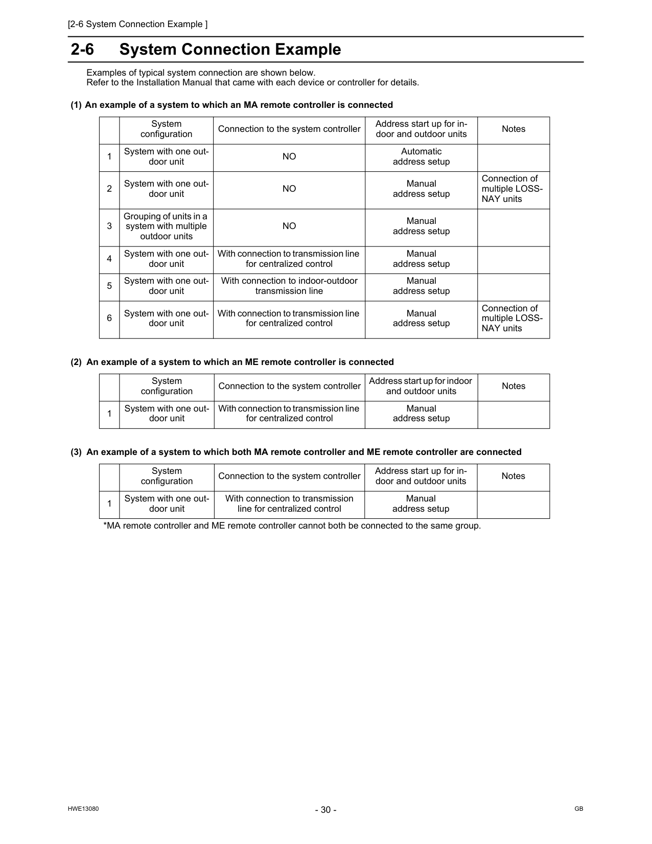
[2-6 System Connection Example ]
Hwe13080
Gb
2-6 System Connection Example Examples of typical system connection are shown below. Refer to the Installation Manual that came with each device or controller for details. (1) An example of a system to which an MA remote controller is connected (2) An example of a system to which an ME remote controller is connected (3) An example of a system to which both MA remote controller and ME remote controller are connected System configuration Connection to the system controller Address start up for in- door and outdoor units Notes 1 System with one out- door unitNo
Automatic address setup 2 System with one out- door unitNo
Manual address setup Connection of multiple LOSS- NAY units 3 Grouping of units in a system with multiple outdoor unitsNo
Manual address setup 4 System with one out- door unit With connection to transmission line for centralized control Manual address setup 5 System with one out- door unit With connection to indoor-outdoor transmission line Manual address setup 6 System with one out- door unit With connection to transmission line for centralized control Manual address setup Connection of multiple LOSS- NAY units System configuration Connection to the system controller Address start up for indoor and outdoor units Notes 1 System with one out- door unit With connection to transmission line for centralized control Manual address setup System configuration Connection to the system controller Address start up for in- door and outdoor units Notes 1 System with one out- door unit With connection to transmission line for centralized control Manual address setup *MA remote controller and ME remote controller cannot both be connected to the same group.
[2-6 System Connection Example ]
Hwe13080
Gb
2 Restrictions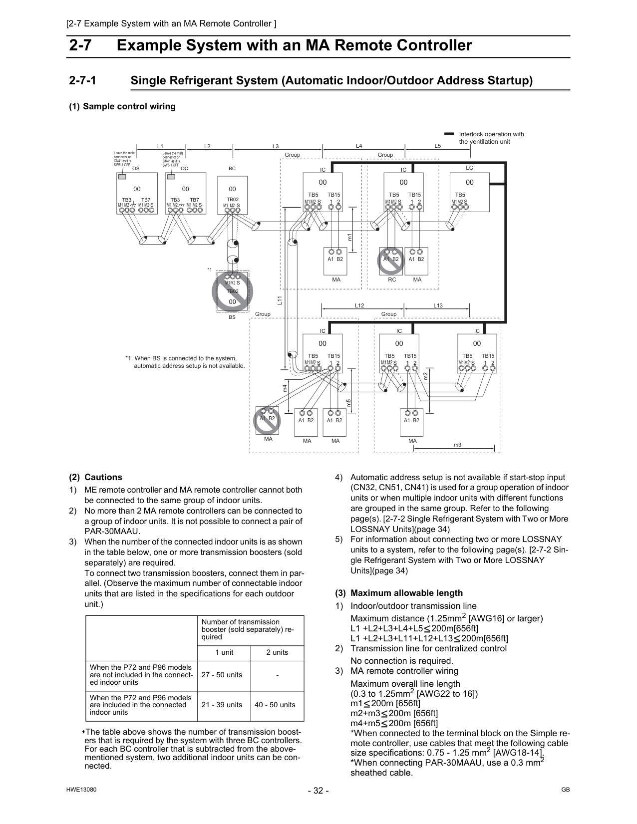
Gb
Hwe13080
2-7 Example System with an MA Remote Controller 2-7-1 Single Refrigerant System (Automatic Indoor/Outdoor Address Startup) (1) Sample control wiring (2) Cautions 1) ME remote controller and MA remote controller cannot both be connected to the same group of indoor units. 2) No more than 2 MA remote controllers can be connected to a group of indoor units. It is not possible to connect a pair ofPar-30Maau.
3) When the number of the connected indoor units is as shown in the table below, one or more transmission boosters (sold separately) are required. To connect two transmission boosters, connect them in par- allel. (Observe the maximum number of connectable indoor units that are listed in the specifications for each outdoor unit.) The table above shows the number of transmission boost- ers that is required by the system with three BC controllers. For each BC controller that is subtracted from the above- mentioned system, two additional indoor units can be con- nected. 4) Automatic address setup is not available if start-stop input (CN32, CN51, CN41) is used for a group operation of indoor units or when multiple indoor units with different functions are grouped in the same group. Refer to the following page(s). [2-7-2 Single Refrigerant System with Two or More LOSSNAY Units](page 34) 5) For information about connecting two or more LOSSNAY units to a system, refer to the following page(s). [2-7-2 Sin- gle Refrigerant System with Two or More LOSSNAY Units](page 34) (3) Maximum allowable length 1) Indoor/outdoor transmission line Maximum distance (1.25mm2 [AWG16] or larger)L1 +L2+L3+L4+L5
200m[656ft]L1 +L2+L3+L11+L12+L13
200m[656ft] 2) Transmission line for centralized control No connection is required. 3) MA remote controller wiring Maximum overall line length (0.3 to 1.25mm2 [AWG22 to 16]) m1 200m [656ft] m2+m3 200m [656ft] m4+m5 200m [656ft] *When connected to the terminal block on the Simple re- mote controller, use cables that meet the following cable size specifications: 0.75 - 1.25 mm2 [AWG18-14]. *When connecting PAR-30MAAU, use a 0.3 mm2 sheathed cable.Ic
Tb5
M1M2
M1M2
M1M2
M1M2
M1M2
M1M2
S
Tb15
1 2 00Ic
Tb5
S
Tb15
1 2 00A1 B2
Ma
A1 B2
Ma
A1 B2
Rc
Lc
Tb5
S
00Ic
Tb5
S
1 2Tb15
Ic
Tb5
S
Tb15
1 2 00 00Ic
Tb5
S
Tb15
1 2 00A1 B2
Ma
A1 B2
Ma
A1 B2
Ma
Group Group Group GroupA1 B2
Ma
m1L11
m2L4
L5
L12
L13
m3 m5 m4 Interlock operation with the ventilation unit *1. When BS is connected to the system, automatic address setup is not available.Bc
00Oc
00Tb7
M1 M2
S
Tb3
Os
00Tb7
M1 M2
M1 M2
M1 M2
S
Tb3
Tb02
M1 M2 S
*1Bs
Tb02
00S
M1M2
L3
L1
L2
Leave the male connector on CN41 as it is.Sw5-1 Off
Leave the male connector on CN41 as it is.Sw5-1 Off
Number of transmission booster (sold separately) re- quired 1 unit 2 units When the P72 and P96 models are not included in the connect- ed indoor units 27 - 50 units
[2-7 Example System with an MA Remote Controller ] 33
Hwe13080
Gb
2 Restrictions (4) Wiring method 1) Indoor/outdoor transmission line Daisy-chain terminals M1 and M2 of the terminal block for indoor-outdoor transmission line (TB3) on the outdoor units (OC and OS), of the terminal block for indoor-out- door transmission line (TB02) on the main BC controller (BC), and of the terminal block for indoor-outdoor trans- mission line (TB5) on each indoor unit (IC). (Non-polar- ized two-wire) Only use shielded cables. The outdoor units in the same refrigerant circuit are au- tomatically designated as OC and OS in the order of ca- pacity from large to small (if two or more units have the same capacity, in the order of address from small to large). Shielded cable connection Daisy-chain the ground terminal ( ) on the outdoor units (OC and OS), the S terminal of the terminal block (TB02) on the BC controller (BC), and the S terminal of the terminal block (TB5) on the indoor unit (IC) with the shield of the shielded cable. 2) Transmission line for centralized control No connection is required. 3) MA remote controller wiring Connect terminals 1 and 2 on the terminal block for MA remote controller line (TB15) on the indoor unit (IC) to the terminal block on the MA remote controller (MA). (Non-polarized two-wire) When 2 remote controllers are connected to the sys- tem When 2 remote controllers are connected to the system, connect terminals 1 and 2 of the terminal block (TB15) on the indoor unit (IC) to the terminal block on the two MA remote controllers. Set one of the MA remote controllers as a sub controller. (Refer to the Instruction Manual for the MA remote con- troller for the setting method.) Group operation of indoor units To perform a group operation of indoor units (IC), daisy- chain terminals 1 and 2 on the terminal block (TB15) on all indoor units (IC) in the same group, and then connect terminals 1 and 2 on the terminal block (TB15) on the in- door unit on one end to the terminal block on the MA re- motecontroller. (Non-polarized two-wire) When performing a group operation of indoor units that have different functions, "Automatic indoor/outdoor ad- dresssetup" is not available. 4) LOSSNAY connection Connect terminals M1 and M2 on the terminal block(TB5) on the indoor unit (IC) to the appropriate ter- minals on the terminal block (TB5) on LOSSNAY (LC). (Non-polarized two-wire) Interlock operation setting with all the indoor units in the same system will automatically be made. (It is required that the Lossnay unit be turned on before the outdoo- runit.) For information about certain types of systems (1. Sys- tems in which the LOSSNAY unit is interlocked with only part of the indoor units, 2. Systems in which the LOSS- NAY unit is operated independently from the indoor units, 3. Systems in which more than 16 indoor units are interlocked with the LOSSNAY unit, and 4. Systems to which two ore more LOSSNAY units are connected), re- fer to the following page(s). [2-7-2 Single Refrigerant System with Two or More LOSSNAY Units](page 34) 5) Switch setting Address setting is required as follows. (5) Address setting method The outdoor units in the same refrigerant circuit are automatically designated as OC and OS. They are designated as OC and OS in the descending order of capacity (ascending order of address if the capacities are the same). Proce- dures Unit or controller Address set- ting range Setting method Notes Factory setting 1 Indoor unit Main unitIc
No settings required.Ic
2Lossnay
Lc
No settings required.Ma
remote con- troller Main remote con- trollerMa
No settings required.Ma
Sub remote con- troller Settings to be made with the Sub/Main switch 4 Outdoor unitOc
Os
No settings required.Bc
controllerBc
No settings required.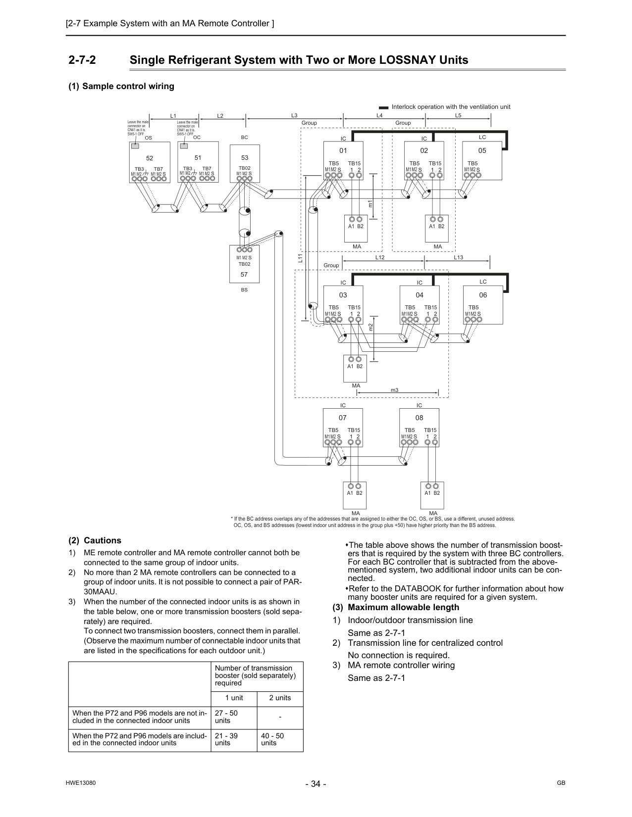
Gb
Hwe13080
2-7-2 Single Refrigerant System with Two or More LOSSNAY Units (1) Sample control wiring (2) Cautions 1) ME remote controller and MA remote controller cannot both be connected to the same group of indoor units. 2) No more than 2 MA remote controllers can be connected to a group of indoor units. It is not possible to connect a pair of PAR-30Maau.
3) When the number of the connected indoor units is as shown in the table below, one or more transmission boosters (sold sepa- rately) are required. To connect two transmission boosters, connect them in parallel. (Observe the maximum number of connectable indoor units that are listed in the specifications for each outdoor unit.) The table above shows the number of transmission boost- ers that is required by the system with three BC controllers. For each BC controller that is subtracted from the above- mentioned system, two additional indoor units can be con- nected. Refer to the DATABOOK for further information about how many booster units are required for a given system. (3) Maximum allowable length 1) Indoor/outdoor transmission line Same as 2-7-1 2) Transmission line for centralized control No connection is required. 3) MA remote controller wiring Same as 2-7-1L3
Bc
53Oc
51Tb7
S
Tb3
Tb02
S
Ic
Tb5
S
Tb15
1 2 01Ic
Tb5
S
Tb15
1 2 02A1 B2
Ma
A1 B2
Ma
Lc
Tb5
S
05Ic
Tb5
S
1 2Tb15
Ic
Tb5
S
Tb15
1 2 04 03Lc
Tb5
S
06A1 B2
Ma
Ic
Tb5
S
1 2Tb15
Ic
Tb5
S
Tb15
1 2 08 07A1 B2
Ma
A1 B2
Ma
M1M2
M1M2
L11
L4
L5
L12
L13
Os
52Tb7
M1 M2
M1 M2
M1 M2
M1 M2
M1 M2
M1M2
M1M2
M1M2
M1M2
M1M2
M1M2
S
Tb3
M1 M2
Tb02
S
57Bs
L1
L2
Group Group Group Interlock operation with the ventilation unit Leave the male connector on CN41 as it is.Sw5-1 Off
Leave the male connector on CN41 as it is.Sw5-1 Off
m1 m2 m3 Number of transmission booster (sold separately) required 1 unit 2 units When the P72 and P96 models are not in- cluded in the connected indoor units 27 - 50 units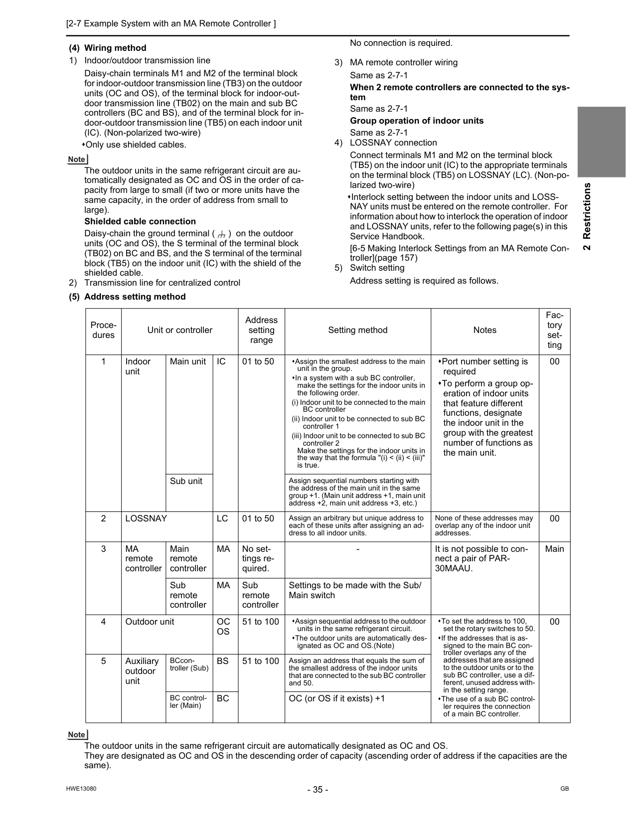
[2-7 Example System with an MA Remote Controller ] 35
Hwe13080
Gb
2 Restrictions (4) Wiring method 1) Indoor/outdoor transmission line Daisy-chain terminals M1 and M2 of the terminal block for indoor-outdoor transmission line (TB3) on the outdoor units (OC and OS), of the terminal block for indoor-out- door transmission line (TB02) on the main and sub BC controllers (BC and BS), and of the terminal block for in- door-outdoor transmission line (TB5) on each indoor unit (IC). (Non-polarized two-wire) Only use shielded cables. The outdoor units in the same refrigerant circuit are au- tomatically designated as OC and OS in the order of ca- pacity from large to small (if two or more units have the same capacity, in the order of address from small to large). Shielded cable connection Daisy-chain the ground terminal ( ) on the outdoor units (OC and OS), the S terminal of the terminal block (TB02) on BC and BS, and the S terminal of the terminal block (TB5) on the indoor unit (IC) with the shield of the shielded cable. 2) Transmission line for centralized control No connection is required. 3) MA remote controller wiring Same as 2-7-1 When 2 remote controllers are connected to the sys- tem Same as 2-7-1 Group operation of indoor units Same as 2-7-1 4) LOSSNAY connection Connect terminals M1 and M2 on the terminal block (TB5) on the indoor unit (IC) to the appropriate terminals on the terminal block (TB5) on LOSSNAY (LC). (Non-po- larized two-wire) Interlock setting between the indoor units and LOSS- NAY units must be entered on the remote controller. For information about how to interlock the operation of indoor and LOSSNAY units, refer to the following page(s) in this Service Handbook. [6-5 Making Interlock Settings from an MA Remote Con- troller](page 157) 5) Switch setting Address setting is required as follows. (5) Address setting method The outdoor units in the same refrigerant circuit are automatically designated as OC and OS. They are designated as OC and OS in the descending order of capacity (ascending order of address if the capacities are the same). Proce- dures Unit or controller Address setting range Setting method Notes Fac- tory set- ting 1 Indoor unit Main unitIc
01 to 50 Assign the smallest address to the main unit in the group. In a system with a sub BC controller, make the settings for the indoor units in the following order. (i) Indoor unit to be connected to the main BC controller (ii) Indoor unit to be connected to sub BC controller 1 (iii) Indoor unit to be connected to sub BC controller 2 Make the settings for the indoor units in the way that the formula "(i) < (ii) < (iii)" is true. Port number setting is required To perform a group op- eration of indoor units that feature different functions, designate the indoor unit in the group with the greatest number of functions as the main unit. 00 Sub unit Assign sequential numbers starting with the address of the main unit in the same group +1. (Main unit address +1, main unit address +2, main unit address +3, etc.) 2Lossnay
Lc
01 to 50 Assign an arbitrary but unique address to each of these units after assigning an ad- dress to all indoor units. None of these addresses may overlap any of the indoor unit addresses. 00 3Ma
remote controller Main remote controllerMa
No set- tings re- quired.30Maau.
Main Sub remote controllerMa
Sub remote controller Settings to be made with the Sub/ Main switch 4 Outdoor unitOc
Os
51 to 100 Assign sequential address to the outdoor units in the same refrigerant circuit. The outdoor units are automatically des- ignated as OC and OS.(Note) To set the address to 100, set the rotary switches to 50. If the addresses that is as- signed to the main BC con- troller overlaps any of the addresses that are assigned to the outdoor units or to the sub BC controller, use a dif- ferent, unused address with- in the setting range. The use of a sub BC control- ler requires the connection of a main BC controller. 00 5 Auxiliary outdoor unit BCcon- troller (Sub)Bs
51 to 100 Assign an address that equals the sum of the smallest address of the indoor units that are connected to the sub BC controller and 50. BC control- ler (Main)Bc
OC (or OS if it exists) +1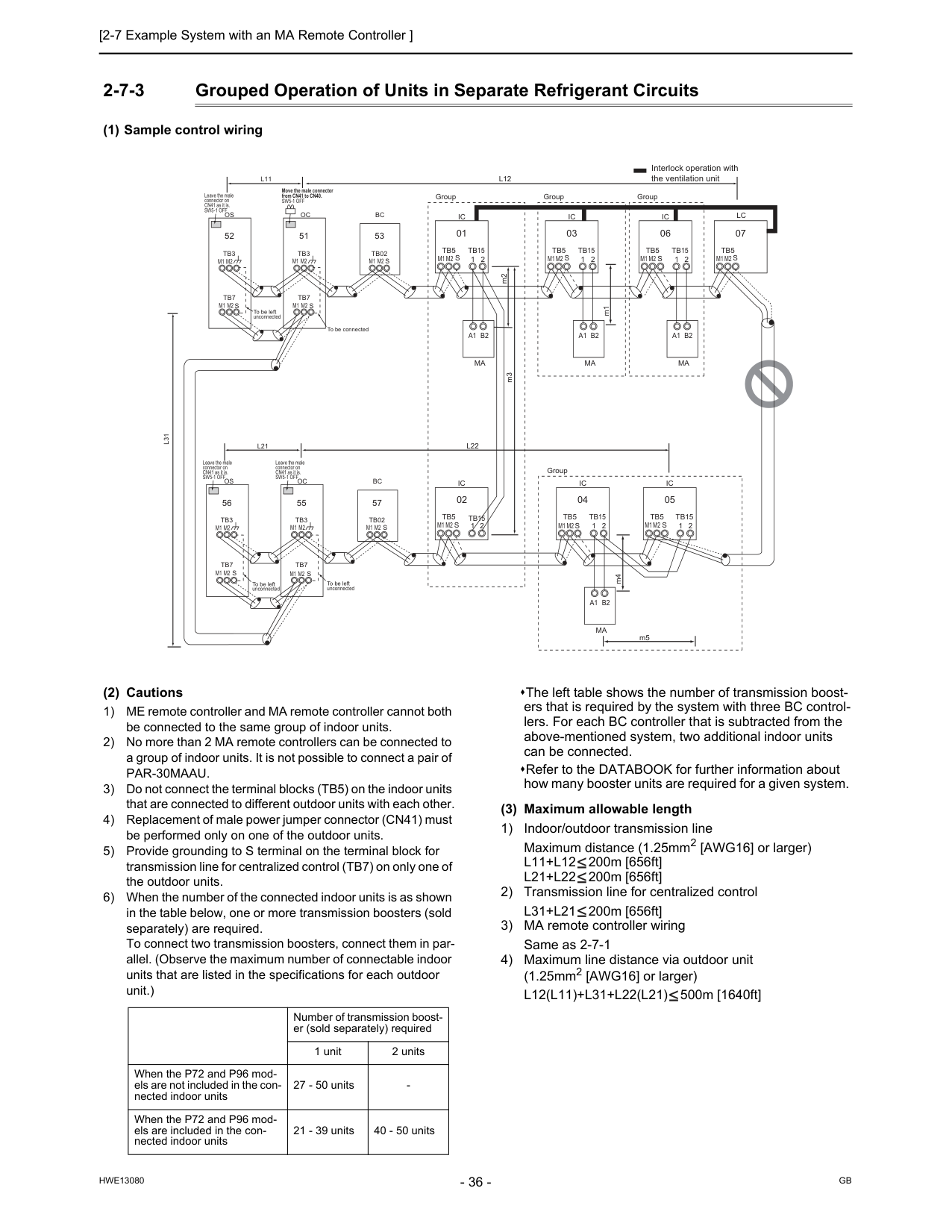
Gb
Hwe13080
2-7-3 Grouped Operation of Units in Separate Refrigerant Circuits (1) Sample control wiring (2) Cautions 1) ME remote controller and MA remote controller cannot both be connected to the same group of indoor units. 2) No more than 2 MA remote controllers can be connected to a group of indoor units. It is not possible to connect a pair ofPar-30Maau.
3) Do not connect the terminal blocks (TB5) on the indoor units that are connected to different outdoor units with each other. 4) Replacement of male power jumper connector (CN41) must be performed only on one of the outdoor units. 5) Provide grounding to S terminal on the terminal block for transmission line for centralized control (TB7) on only one of the outdoor units. 6) When the number of the connected indoor units is as shown in the table below, one or more transmission boosters (sold separately) are required. To connect two transmission boosters, connect them in par- allel. (Observe the maximum number of connectable indoor units that are listed in the specifications for each outdoor unit.) The left table shows the number of transmission boost- ers that is required by the system with three BC control- lers. For each BC controller that is subtracted from the above-mentioned system, two additional indoor units can be connected. Refer to the DATABOOK for further information about how many booster units are required for a given system. (3) Maximum allowable length 1) Indoor/outdoor transmission line Maximum distance (1.25mm2 [AWG16] or larger)L11+L12
200m [656ft]L21+L22
200m [656ft] 2) Transmission line for centralized controlL31+L21
200m [656ft] 3) MA remote controller wiring Same as 2-7-1 4) Maximum line distance via outdoor unit (1.25mm2 [AWG16] or larger)L12(L11)+L31+L22(L21)
500m [1640ft]Ic
Tb5
S
Tb15
1 2 01Ic
Tb5
S
Tb15
1 2 03A1 B2
Ma
A1 B2
Ma
Lc
Tb5
S
07Ic
Tb5
S
1 2Tb15
Ic
Tb5
S
Tb15
1 2 1 2 04 02Ic
Tb5
Tb15
S
05A1 B2
Ma
GroupIc
Tb5
S
Tb15
1 2 06A1 B2
Ma
Group Group Group To be left unconnected m2 m3 Interlock operation with the ventilation unitL12
L22
L11
L21
Oc
Move the male connector from CN41 to CN40.Sw5-1 Off
Leave the male connector on CN41 as it is.Sw5-1 Off
Leave the male connector on CN41 as it is.Sw5-1 Off
Leave the male connector on CN41 as it is.Sw5-1 Off
Tb3
Tb7
S
51Os
Tb3
Tb7
M1 M2
M1 M2
M1 M2
M1 M2
M1 M2
M1 M2
M1 M2
M1 M2
M1 M2
M1 M2
M1 M2
M1 M2
M1 M2
M1 M2
M1 M2
M1 M2
M1 M2
S
52Oc
Tb3
Tb7
S
55Os
Tb3
Tb7
S
56L31
To be left unconnectedS
S
Bc
Tb02
53Bc
Tb02
57 To be left unconnected To be connected m1 m4 m5 Number of transmission boost- er (sold separately) required 1 unit 2 units When the P72 and P96 mod- els are not included in the con- nected indoor units 27 - 50 units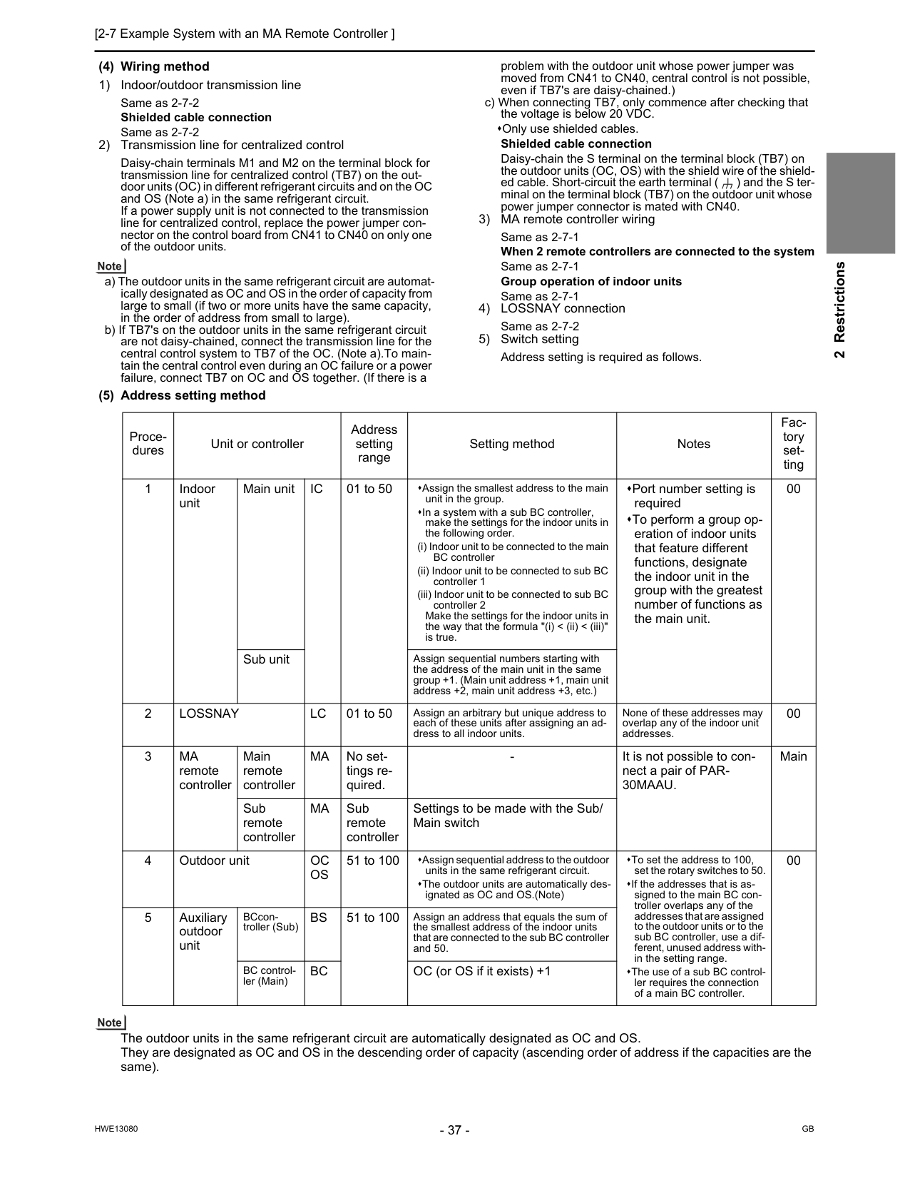
[2-7 Example System with an MA Remote Controller ] 37
Hwe13080
Gb
2 Restrictions (4) Wiring method 1) Indoor/outdoor transmission line Same as 2-7-2 Shielded cable connection Same as 2-7-2 2) Transmission line for centralized control Daisy-chain terminals M1 and M2 on the terminal block for transmission line for centralized control (TB7) on the out- door units (OC) in different refrigerant circuits and on the OC and OS (Note a) in the same refrigerant circuit. If a power supply unit is not connected to the transmission line for centralized control, replace the power jumper con- nector on the control board from CN41 to CN40 on only one of the outdoor units. a) The outdoor units in the same refrigerant circuit are automat- ically designated as OC and OS in the order of capacity from large to small (if two or more units have the same capacity, in the order of address from small to large). b) If TB7's on the outdoor units in the same refrigerant circuit are not daisy-chained, connect the transmission line for the central control system to TB7 of the OC. (Note a).To main- tain the central control even during an OC failure or a power failure, connect TB7 on OC and OS together. (If there is a problem with the outdoor unit whose power jumper was moved from CN41 to CN40, central control is not possible, even if TB7's are daisy-chained.) c) When connecting TB7, only commence after checking that the voltage is below 20 VDC. Only use shielded cables. Shielded cable connection Daisy-chain the S terminal on the terminal block (TB7) on the outdoor units (OC, OS) with the shield wire of the shield- ed cable. Short-circuit the earth terminal ( ) and the S ter- minal on the terminal block (TB7) on the outdoor unit whose power jumper connector is mated with CN40. 3) MA remote controller wiring Same as 2-7-1 When 2 remote controllers are connected to the system Same as 2-7-1 Group operation of indoor units Same as 2-7-1 4) LOSSNAY connection Same as 2-7-2 5) Switch setting Address setting is required as follows. (5) Address setting method The outdoor units in the same refrigerant circuit are automatically designated as OC and OS. They are designated as OC and OS in the descending order of capacity (ascending order of address if the capacities are the same). Proce- dures Unit or controller Address setting range Setting method Notes Fac- tory set- ting 1 Indoor unit Main unitIc
01 to 50 Assign the smallest address to the main unit in the group. In a system with a sub BC controller, make the settings for the indoor units in the following order. (i) Indoor unit to be connected to the main BC controller (ii) Indoor unit to be connected to sub BC controller 1 (iii) Indoor unit to be connected to sub BC controller 2 Make the settings for the indoor units in the way that the formula "(i) < (ii) < (iii)" is true. Port number setting is required To perform a group op- eration of indoor units that feature different functions, designate the indoor unit in the group with the greatest number of functions as the main unit. 00 Sub unit Assign sequential numbers starting with the address of the main unit in the same group +1. (Main unit address +1, main unit address +2, main unit address +3, etc.) 2Lossnay
Lc
01 to 50 Assign an arbitrary but unique address to each of these units after assigning an ad- dress to all indoor units. None of these addresses may overlap any of the indoor unit addresses. 00 3Ma
remote controller Main remote controllerMa
No set- tings re- quired.30Maau.
Main Sub remote controllerMa
Sub remote controller Settings to be made with the Sub/ Main switch 4 Outdoor unitOc
Os
51 to 100 Assign sequential address to the outdoor units in the same refrigerant circuit. The outdoor units are automatically des- ignated as OC and OS.(Note) To set the address to 100, set the rotary switches to 50. If the addresses that is as- signed to the main BC con- troller overlaps any of the addresses that are assigned to the outdoor units or to the sub BC controller, use a dif- ferent, unused address with- in the setting range. The use of a sub BC control- ler requires the connection of a main BC controller. 00 5 Auxiliary outdoor unit BCcon- troller (Sub)Bs
51 to 100 Assign an address that equals the sum of the smallest address of the indoor units that are connected to the sub BC controller and 50. BC control- ler (Main)Bc
OC (or OS if it exists) +1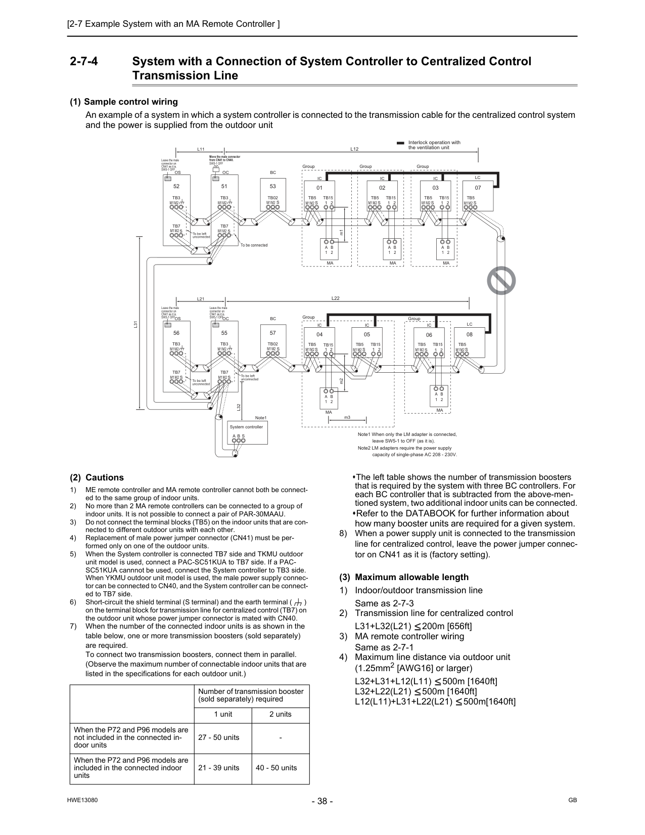
Gb
Hwe13080
2-7-4 System with a Connection of System Controller to Centralized Control Transmission Line (1) Sample control wiring An example of a system in which a system controller is connected to the transmission cable for the centralized control system and the power is supplied from the outdoor unit (2) Cautions 1) ME remote controller and MA remote controller cannot both be connect- ed to the same group of indoor units. 2) No more than 2 MA remote controllers can be connected to a group of indoor units. It is not possible to connect a pair of PAR-30MAAU. 3) Do not connect the terminal blocks (TB5) on the indoor units that are con- nected to different outdoor units with each other. 4) Replacement of male power jumper connector (CN41) must be per- formed only on one of the outdoor units. 5) When the System controller is connected TB7 side and TKMU outdoor unit model is used, connect a PAC-SC51KUA to TB7 side. If a PAC- SC51KUA cannnot be used, connect the System controller to TB3 side. When YKMU outdoor unit model is used, the male power supply connec- tor can be connected to CN40, and the System controller can be connect- ed to TB7 side. 6) Short-circuit the shield terminal (S terminal) and the earth terminal ( ) on the terminal block for transmission line for centralized control (TB7) on the outdoor unit whose power jumper connector is mated with CN40. 7) When the number of the connected indoor units is as shown in the table below, one or more transmission boosters (sold separately) are required. To connect two transmission boosters, connect them in parallel. (Observe the maximum number of connectable indoor units that are listed in the specifications for each outdoor unit.) The left table shows the number of transmission boosters that is required by the system with three BC controllers. For each BC controller that is subtracted from the above-men- tioned system, two additional indoor units can be connected. Refer to the DATABOOK for further information about how many booster units are required for a given system. 8) When a power supply unit is connected to the transmission line for centralized control, leave the power jumper connec- tor on CN41 as it is (factory setting). (3) Maximum allowable length 1) Indoor/outdoor transmission line Same as 2-7-3 2) Transmission line for centralized controlL31+L32(L21)
200m [656ft] 3) MA remote controller wiring Same as 2-7-1 4) Maximum line distance via outdoor unit (1.25mm2 [AWG16] or larger)L32+L31+L12(L11)
500m [1640ft]L32+L22(L21)
500m [1640ft]L12(L11)+L31+L22(L21)
500m[1640ft]Ic
Tb5
S
Tb15
1 2 01Ic
Tb5
S
Tb15
1 2 02A
1B
2Ma
A
1B
2Ma
Lc
Tb5
S
07Ic
Tb5
S
1 2Tb15
Ic
Tb5
S
Tb15
1 2 05 04Lc
Tb5
S
08Ic
Tb5
S
Tb15
1 2 03A
1B
2Ma
Ic
Tb5
S
Tb15
1 2 06A
1B
2Ma
A
1B
2Ma
m3L31
System controllerA B S
Note1L32
Oc
To be connected m2 m1 Note1 When only the LM adapter is connected, leave SW5-1 to OFF (as it is). Note2 LM adapters require the power supply capacity of single-phase AC 208 - 230V.Tb3
Tb7
S
51Os
Tb3
Tb7
M1M2
M1M2
M1M2
M1M2
M1M2
M1M2
M1M2
M1M2
M1M2
M1M2
M1M2
M1M2
M1M2
M1M2
M1M2
M1M2
M1M2
M1M2
S
52Oc
Tb3
Tb7
S
55Os
Tb3
Tb7
S
56 Group Group Group Group Group Interlock operation with the ventilation unit Move the male connector from CN41 to CN40.Sw5-1 Off
Leave the male connector on CN41 as it is.Sw5-1 Off
Leave the male connector on CN41 as it is.Sw5-1 Off
Leave the male connector on CN41 as it is.Sw5-1 Off
To be left unconnected To be left unconnected To be left unconnectedS
Bc
Tb02
53S
Bc
Tb02
57L22
L21
L12
L11
Number of transmission booster (sold separately) required 1 unit 2 units When the P72 and P96 models are not included in the connected in- door units 27 - 50 units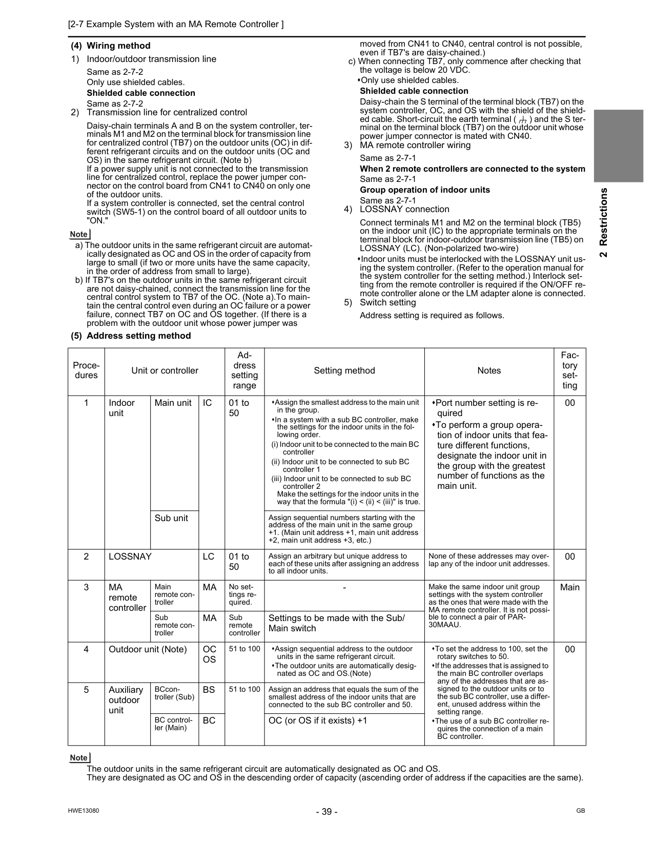
[2-7 Example System with an MA Remote Controller ] 39
Hwe13080
Gb
2 Restrictions (4) Wiring method 1) Indoor/outdoor transmission line Same as 2-7-2 Only use shielded cables. Shielded cable connection Same as 2-7-2 2) Transmission line for centralized control Daisy-chain terminals A and B on the system controller, ter- minals M1 and M2 on the terminal block for transmission line for centralized control (TB7) on the outdoor units (OC) in dif- ferent refrigerant circuits and on the outdoor units (OC and OS) in the same refrigerant circuit. (Note b) If a power supply unit is not connected to the transmission line for centralized control, replace the power jumper con- nector on the control board from CN41 to CN40 on only one of the outdoor units. If a system controller is connected, set the central control switch (SW5-1) on the control board of all outdoor units to"On."
a) The outdoor units in the same refrigerant circuit are automat- ically designated as OC and OS in the order of capacity from large to small (if two or more units have the same capacity, in the order of address from small to large). b) If TB7's on the outdoor units in the same refrigerant circuit are not daisy-chained, connect the transmission line for the central control system to TB7 of the OC. (Note a).To main- tain the central control even during an OC failure or a power failure, connect TB7 on OC and OS together. (If there is a problem with the outdoor unit whose power jumper was moved from CN41 to CN40, central control is not possible, even if TB7's are daisy-chained.) c) When connecting TB7, only commence after checking that the voltage is below 20 VDC. Only use shielded cables. Shielded cable connection Daisy-chain the S terminal of the terminal block (TB7) on the system controller, OC, and OS with the shield of the shield- ed cable. Short-circuit the earth terminal ( ) and the S ter- minal on the terminal block (TB7) on the outdoor unit whose power jumper connector is mated with CN40. 3) MA remote controller wiring Same as 2-7-1 When 2 remote controllers are connected to the system Same as 2-7-1 Group operation of indoor units Same as 2-7-1 4) LOSSNAY connection Connect terminals M1 and M2 on the terminal block (TB5) on the indoor unit (IC) to the appropriate terminals on the terminal block for indoor-outdoor transmission line (TB5) on LOSSNAY (LC). (Non-polarized two-wire) Indoor units must be interlocked with the LOSSNAY unit us- ing the system controller. (Refer to the operation manual for the system controller for the setting method.) Interlock set- ting from the remote controller is required if the ON/OFF re- mote controller alone or the LM adapter alone is connected. 5) Switch setting Address setting is required as follows. (5) Address setting method The outdoor units in the same refrigerant circuit are automatically designated as OC and OS. They are designated as OC and OS in the descending order of capacity (ascending order of address if the capacities are the same). Proce- dures Unit or controller Ad- dress setting range Setting method Notes Fac- tory set- ting 1 Indoor unit Main unitIc
01 to 50 Assign the smallest address to the main unit in the group. In a system with a sub BC controller, make the settings for the indoor units in the fol- lowing order. (i) Indoor unit to be connected to the main BC controller (ii) Indoor unit to be connected to sub BC controller 1 (iii) Indoor unit to be connected to sub BC controller 2 Make the settings for the indoor units in the way that the formula "(i) < (ii) < (iii)" is true. Port number setting is re- quired To perform a group opera- tion of indoor units that fea- ture different functions, designate the indoor unit in the group with the greatest number of functions as the main unit. 00 Sub unit Assign sequential numbers starting with the address of the main unit in the same group +1. (Main unit address +1, main unit address +2, main unit address +3, etc.) 2Lossnay
Lc
01 to 50 Assign an arbitrary but unique address to each of these units after assigning an address to all indoor units. None of these addresses may over- lap any of the indoor unit addresses. 00 3Ma
remote controller Main remote con- trollerMa
No set- tings re- quired.30Maau.
Main Sub remote con- trollerMa
Sub remote controller Settings to be made with the Sub/ Main switch 4 Outdoor unit (Note)Oc
Os
51 to 100 Assign sequential address to the outdoor units in the same refrigerant circuit. The outdoor units are automatically desig- nated as OC and OS.(Note) To set the address to 100, set the rotary switches to 50. If the addresses that is assigned to the main BC controller overlaps any of the addresses that are as- signed to the outdoor units or to the sub BC controller, use a differ- ent, unused address within the setting range. The use of a sub BC controller re- quires the connection of a main BC controller. 00 5 Auxiliary outdoor unit BCcon- troller (Sub)Bs
51 to 100 Assign an address that equals the sum of the smallest address of the indoor units that are connected to the sub BC controller and 50. BC control- ler (Main)Bc
OC (or OS if it exists) +1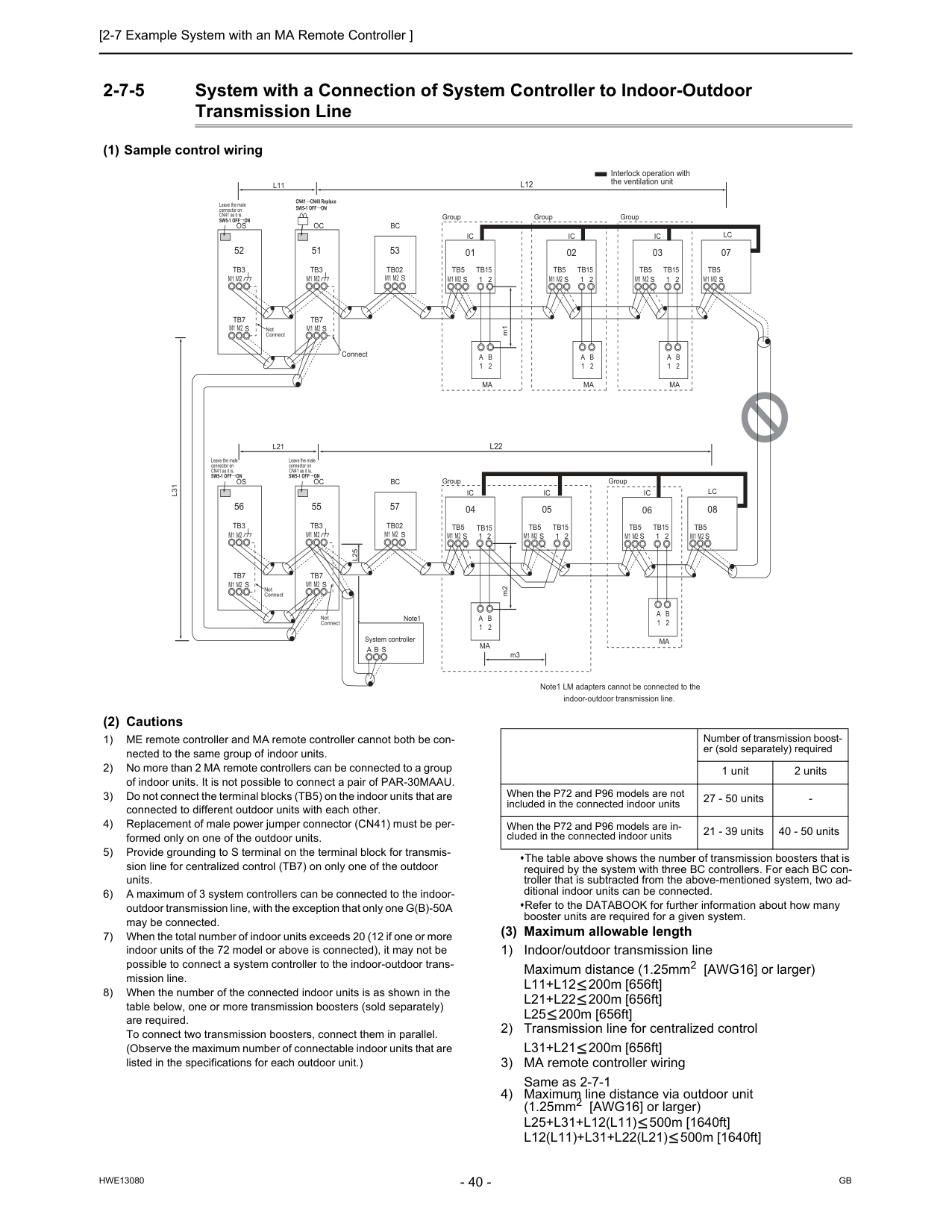
Gb
Hwe13080
2-7-5 System with a Connection of System Controller to Indoor-Outdoor Transmission Line (1) Sample control wiring (2) Cautions 1) ME remote controller and MA remote controller cannot both be con- nected to the same group of indoor units. 2) No more than 2 MA remote controllers can be connected to a group of indoor units. It is not possible to connect a pair of PAR-30MAAU. 3) Do not connect the terminal blocks (TB5) on the indoor units that are connected to different outdoor units with each other. 4) Replacement of male power jumper connector (CN41) must be per- formed only on one of the outdoor units. 5) Provide grounding to S terminal on the terminal block for transmis- sion line for centralized control (TB7) on only one of the outdoor units. 6) A maximum of 3 system controllers can be connected to the indoor- outdoor transmission line, with the exception that only one G(B)-50A may be connected. 7) When the total number of indoor units exceeds 20 (12 if one or more indoor units of the 72 model or above is connected), it may not be possible to connect a system controller to the indoor-outdoor trans- mission line. 8) When the number of the connected indoor units is as shown in the table below, one or more transmission boosters (sold separately) are required. To connect two transmission boosters, connect them in parallel. (Observe the maximum number of connectable indoor units that are listed in the specifications for each outdoor unit.) The table above shows the number of transmission boosters that is required by the system with three BC controllers. For each BC con- troller that is subtracted from the above-mentioned system, two ad- ditional indoor units can be connected. Refer to the DATABOOK for further information about how many booster units are required for a given system. (3) Maximum allowable length 1) Indoor/outdoor transmission line Maximum distance (1.25mm2 [AWG16] or larger)L11+L12
200m [656ft]L21+L22
200m [656ft]L25
200m [656ft] 2) Transmission line for centralized controlL31+L21
200m [656ft] 3) MA remote controller wiring Same as 2-7-1 4) Maximum line distance via outdoor unit (1.25mm2 [AWG16] or larger)L25+L31+L12(L11)
500m [1640ft]L12(L11)+L31+L22(L21)
500m [1640ft]Ic
Tb5
S
Tb15
1 2 01Ic
Tb5
S
Tb15
1 2 02A
1B
2Ma
A
1B
2Ma
Lc
Tb5
S
07Ic
Tb5
S
1 2Tb15
Ic
Tb5
S
Tb15
1 2 05 04Lc
Tb5
S
08Ic
Tb5
S
Tb15
1 2 03A
1B
2Ma
Ic
Tb5
S
Tb15
1 2 06A
1B
2Ma
A
1B
2Ma
Group Group Group Group Group m3 Interlock operation with the ventilation unitOc
Connect m2 m1 Note1 LM adapters cannot be connected to the indoor-outdoor transmission line.Tb3
Tb7
S
51Os
Tb3
Tb7
S
52Oc
Tb3
Tb7
S
55Os
Tb3
Tb7
S
56L31
A B S
L25
M2
M1
M2
M1
M2
M1
M2
M1
M2
M1
M2
M1
M2
M1
M2
M1
M2
M1
M2
M1
M2
M1
M2
M1
M2
M1
M2
M1
M2
M1
M2
M1
M2
M1
M2
M1
Not Connect Not Connect Not Connect CN41 CN40 ReplaceSw5-1 Off On
Sw5-1 Off On
Leave the male connector on CN41 as it is.Sw5-1 Off On
Leave the male connector on CN41 as it is.Sw5-1 Off On
Leave the male connector on CN41 as it is. System controller Note1S
Bc
Tb02
53S
Bc
Tb02
57L22
L21
L12
L11
Number of transmission boost- er (sold separately) required 1 unit 2 units When the P72 and P96 models are not included in the connected indoor units 27 - 50 units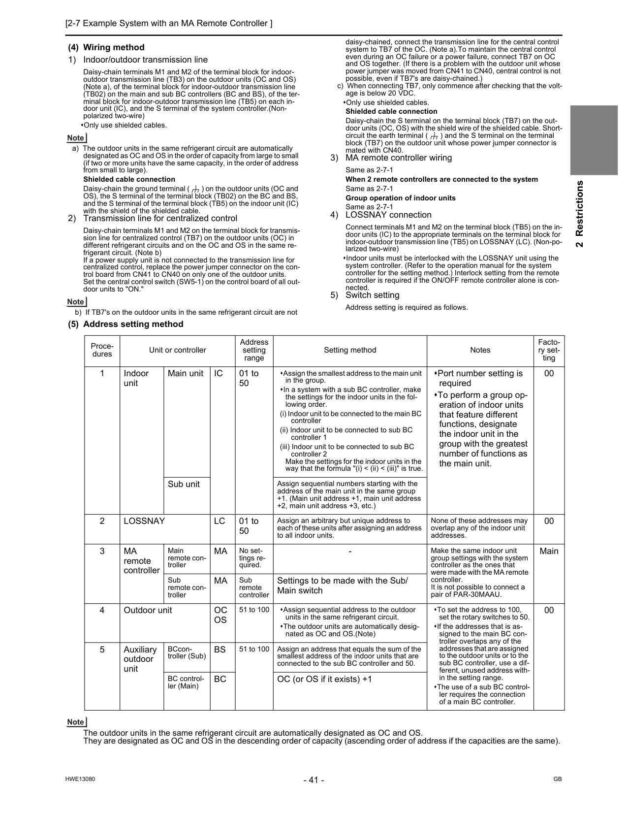
[2-7 Example System with an MA Remote Controller ] 41
Hwe13080
Gb
2 Restrictions (4) Wiring method 1) Indoor/outdoor transmission line Daisy-chain terminals M1 and M2 of the terminal block for indoor- outdoor transmission line (TB3) on the outdoor units (OC and OS) (Note a), of the terminal block for indoor-outdoor transmission line (TB02) on the main and sub BC controllers (BC and BS), of the ter- minal block for indoor-outdoor transmission line (TB5) on each in- door unit (IC), and the S terminal of the system controller.(Non- polarized two-wire) Only use shielded cables. a) The outdoor units in the same refrigerant circuit are automatically designated as OC and OS in the order of capacity from large to small (if two or more units have the same capacity, in the order of address from small to large). Shielded cable connection Daisy-chain the ground terminal ( ) on the outdoor units (OC and OS), the S terminal of the terminal block (TB02) on the BC and BS, and the S terminal of the terminal block (TB5) on the indoor unit (IC) with the shield of the shielded cable. 2) Transmission line for centralized control Daisy-chain terminals M1 and M2 on the terminal block for transmis- sion line for centralized control (TB7) on the outdoor units (OC) in different refrigerant circuits and on the OC and OS in the same re- frigerant circuit. (Note b) If a power supply unit is not connected to the transmission line for centralized control, replace the power jumper connector on the con- trol board from CN41 to CN40 on only one of the outdoor units. Set the central control switch (SW5-1) on the control board of all out- door units to "ON." b) If TB7's on the outdoor units in the same refrigerant circuit are not daisy-chained, connect the transmission line for the central control system to TB7 of the OC. (Note a).To maintain the central control even during an OC failure or a power failure, connect TB7 on OC and OS together. (If there is a problem with the outdoor unit whose power jumper was moved from CN41 to CN40, central control is not possible, even if TB7's are daisy-chained.) c) When connecting TB7, only commence after checking that the volt- age is below 20 VDC. Only use shielded cables. Shielded cable connection Daisy-chain the S terminal on the terminal block (TB7) on the out- door units (OC, OS) with the shield wire of the shielded cable. Short- circuit the earth terminal ( ) and the S terminal on the terminal block (TB7) on the outdoor unit whose power jumper connector is mated with CN40. 3) MA remote controller wiring Same as 2-7-1 When 2 remote controllers are connected to the system Same as 2-7-1 Group operation of indoor units Same as 2-7-1 4) LOSSNAY connection Connect terminals M1 and M2 on the terminal block (TB5) on the in- door units (IC) to the appropriate terminals on the terminal block for indoor-outdoor transmission line (TB5) on LOSSNAY (LC). (Non-po- larized two-wire) Indoor units must be interlocked with the LOSSNAY unit using the system controller. (Refer to the operation manual for the system controller for the setting method.) Interlock setting from the remote controller is required if the ON/OFF remote controller alone is con- nected. 5) Switch setting Address setting is required as follows. (5) Address setting method The outdoor units in the same refrigerant circuit are automatically designated as OC and OS. They are designated as OC and OS in the descending order of capacity (ascending order of address if the capacities are the same). Proce- dures Unit or controller Address setting range Setting method Notes Facto- ry set- ting 1 Indoor unit Main unitIc
01 to 50 Assign the smallest address to the main unit in the group. In a system with a sub BC controller, make the settings for the indoor units in the fol- lowing order. (i) Indoor unit to be connected to the main BC controller (ii) Indoor unit to be connected to sub BC controller 1 (iii) Indoor unit to be connected to sub BC controller 2 Make the settings for the indoor units in the way that the formula "(i) < (ii) < (iii)" is true. Port number setting is required To perform a group op- eration of indoor units that feature different functions, designate the indoor unit in the group with the greatest number of functions as the main unit. 00 Sub unit Assign sequential numbers starting with the address of the main unit in the same group +1. (Main unit address +1, main unit address +2, main unit address +3, etc.) 2Lossnay
Lc
01 to 50 Assign an arbitrary but unique address to each of these units after assigning an address to all indoor units. None of these addresses may overlap any of the indoor unit addresses. 00 3Ma
remote controller Main remote con- trollerMa
No set- tings re- quired.Ma
Sub remote controller Settings to be made with the Sub/ Main switch 4 Outdoor unitOc
Os
51 to 100 Assign sequential address to the outdoor units in the same refrigerant circuit. The outdoor units are automatically desig- nated as OC and OS.(Note) To set the address to 100, set the rotary switches to 50. If the addresses that is as- signed to the main BC con- troller overlaps any of the addresses that are assigned to the outdoor units or to the sub BC controller, use a dif- ferent, unused address with- in the setting range. The use of a sub BC control- ler requires the connection of a main BC controller. 00 5 Auxiliary outdoor unit BCcon- troller (Sub)Bs
51 to 100 Assign an address that equals the sum of the smallest address of the indoor units that are connected to the sub BC controller and 50. BC control- ler (Main)Bc
OC (or OS if it exists) +1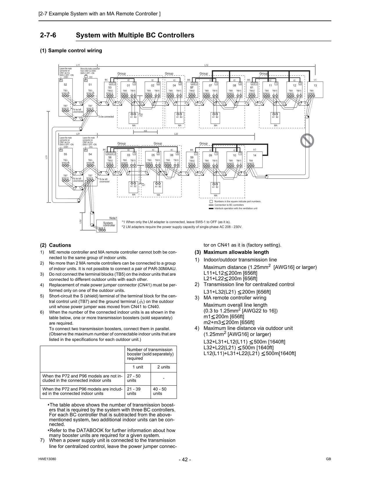
Gb
Hwe13080
2-7-6 System with Multiple BC Controllers (1) Sample control wiring (2) Cautions 1) ME remote controller and MA remote controller cannot both be con- nected to the same group of indoor units. 2) No more than 2 MA remote controllers can be connected to a group of indoor units. It is not possible to connect a pair of PAR-30MAAU. 3) Do not connect the terminal blocks (TB5) on the indoor units that are connected to different outdoor units with each other. 4) Replacement of male power jumper connector (CN41) must be per- formed only on one of the outdoor units. 5) Short-circuit the S (shield) terminal of the terminal block for the cen- tral control unit (TB7) and the ground terminal ( ) on the outdoor unit whose power jumper was moved from CN41 to CN40. 6) When the number of the connected indoor units is as shown in the table below, one or more transmission boosters (sold separately) are required. To connect two transmission boosters, connect them in parallel. (Observe the maximum number of connectable indoor units that are listed in the specifications for each outdoor unit.) The table above shows the number of transmission boost- ers that is required by the system with three BC controllers. For each BC controller that is subtracted from the above- mentioned system, two additional indoor units can be con- nected. Refer to the DATABOOK for further information about how many booster units are required for a given system. 7) When a power supply unit is connected to the transmission line for centralized control, leave the power jumper connec- tor on CN41 as it is (factory setting). (3) Maximum allowable length 1) Indoor/outdoor transmission line Maximum distance (1.25mm2 [AWG16] or larger)L11+L12
200m [656ft]L21+L22
200m [656ft] 2) Transmission line for centralized controlL31+L32(L21)
200m [656ft] 3) MA remote controller wiring Maximum overall line length (0.3 to 1.25mm2 [AWG22 to 16]) m1 200m [656ft] m2+m3 200m [656ft] 4) Maximum line distance via outdoor unit (1.25mm2 [AWG16] or larger)L32+L31+L12(L11)
500m [1640ft]L32+L22(L21)
500m [1640ft]L12(L11)+L31+L22(L21)
500m[1640ft]L11
L21
Oc
Tb3
Tb7
S
51L31
A B S
L32
Os1
Tb3
Tb7
M1M2
S
52Oc
Tb3
Tb7
S
54Os1
Tb3
Tb7
S
55Sw5-1 Off On
Move the male connector from CN41 to CN40 Group Group Group Group Group Group Group To be left unconnected To be left unconnected To be left unconnected To be connectedM1M2
M1M2
M1M2
M1M2
M1M2
M1M2
M1M2
M1M2
*1 When only the LM adapter is connected, leave SW5-1 to OFF (as it is). *2 LM adapters require the power supply capacity of single-phase AC 208 - 230V.Ic
Tb5
S
Tb15
1 2 01Ic
Tb5
S
Tb15
1 2 02Ic
Tb5
S
Tb15
1 2 04Ic
Tb5
S
Tb15
1 2 06A1 B2
Ma
A1 B2
Ma
A1 B2
Ma
Ic
Tb5
S
1 2Tb15
Ic
Tb5
S
Tb15
1 2 05 03L12
L22
Ic
Tb5
S
Tb15
1 2 07Ic
Tb5
S
Tb15
1 2 08A1 B2
Ma
Ic
Tb5
S
Tb15
1 2 09Ic
Tb5
S
Tb15
1 2 10A1 B2
Ma
A1 B2
Ma
Bc
Bc
Tb02
S
53 57Tb02
M1M2 S
Bs
Tb02
S
Bs
Tb02
S
1 1 2 1 2 2 2 1 2 57 1 1 2 1 1Lc
Tb5
S
14 3 2 3 1 Numbers in the square indicate port numbers. Connection to BC controllers 56 59 Interlock operation with the ventilation unitIc
Tb5
S
Tb15
1 2 11Ic
Tb5
S
Tb15
1 2 12A1 B2
Ma
61Bs
Tb02
S
1 2Lc
Tb5
S
13 1 2 m2 m3 m1Sw5-1 Off On
Leave the male connector on CN41 as it is.Sw5-1 Off On
Leave the male connector on CN41 as it is.Sw5-1 Off On
Leave the male connector on CN41 as it is. System controller Note1M1M2
M1M2
M1M2
M1M2
M1M2
M1M2
M1M2
M1M2
M1M2
M1M2
M1M2
M1M2
M1M2
M1M2
M1M2
M1M2
M1M2
Number of transmission booster (sold separately) required 1 unit 2 units When the P72 and P96 models are not in- cluded in the connected indoor units 27 - 50 units
[2-7 Example System with an MA Remote Controller ] 43
Hwe13080
Gb
2 Restrictions (4) Wiring method 1) Indoor/outdoor transmission line Daisy-chain terminals M1 and M2 of the terminal block for indoor-outdoor transmission line (TB3) on the outdoor units (OC and OS) (Note a), of the terminal block for in- door-outdoor transmission line (TB02) on the main and sub BC controllers (BC and BS), and of the terminal block for indoor-outdoor transmission line (TB5) on each indoor unit (IC). (Non-polarized two-wire) Only use shielded cables. a) The outdoor units in the same refrigerant circuit are auto- matically designated as OC and OS in the order of ca- pacity from large to small (if two or more units have the same capacity, in the order of address from small to large). Shielded cable connection Daisy-chain the ground terminal ( ) on the outdoor units (OC and OS), the S terminal of the terminal block (TB02) on the BC and BS, and the S terminal of the terminal block (TB5) on the indoor unit (IC) with the shield of the shielded cable. 2) Transmission line for centralized control Daisy-chain terminals A and B of the system controller, M1 and M2 terminals of TB7 (terminal block for central- ized control system connection) on the outdoor units (OC) in different refrigerant systems, and M1 and M2 ter- minals of TB7 (terminal block for centralized control sys- tem connection) on the outdoor units (OC and OS ) in the same refrigerant circuit. (Note b) If a power supply unit is not connected to the transmis- sion line for centralized control, replace the power jump- er connector on the control board from CN41 to CN40 on only one of the outdoor units. When connecting a system controller, set the centralized control switch (SW5-1) on the control board of all indoor units to "ON." b) If TB7's on the outdoor units in the same refrigerant cir- cuit are not daisy-chained, connect the transmission line for the central control system to TB7 of the OC. (Note a).To maintain the central control even during an OC fail- ure or a power failure, connect TB7 on OC and OS to- gether. (If there is a problem with the outdoor unit whose power jumper was moved from CN41 to CN40, central control is not possible, even if TB7's are daisy-chained.) c) When connecting TB7, only commence after checking that the voltage is below 20 VDC. Only use shielded cables. Shielded cable connection Daisy-chain the S terminal of the terminal block (TB7) on the system controller, OC, and OS with the shield of the shielded cable. Short-circuit the earth terminal ( ) and the S terminal on the terminal block (TB7) on the outdoor unit whose power jumper connector is mated with CN40. 3) MA remote controller wiring Same as 2-7-1 When 2 remote controllers are connected to the sys- tem Same as 2-7-1 Group operation of indoor units Same as 2-7-1 4) LOSSNAY connection Connect terminals M1 and M2 on the terminal block (TB5) on the indoor unit (IC) to the appropriate terminals on the terminal block for indoor-outdoor transmission line (TB5) on LOSSNAY (LC). (Non-polarized two-wire) Indoor units must be interlocked with the LOSSNAY unit using the system controller. (Refer to the operation man- ual for the system controller for the setting method.) In- terlock setting from the remote controller is required if the ON/OFF remote controller alone or the LM adapter alone is connected. 5) Switch setting Address setting is required as follows.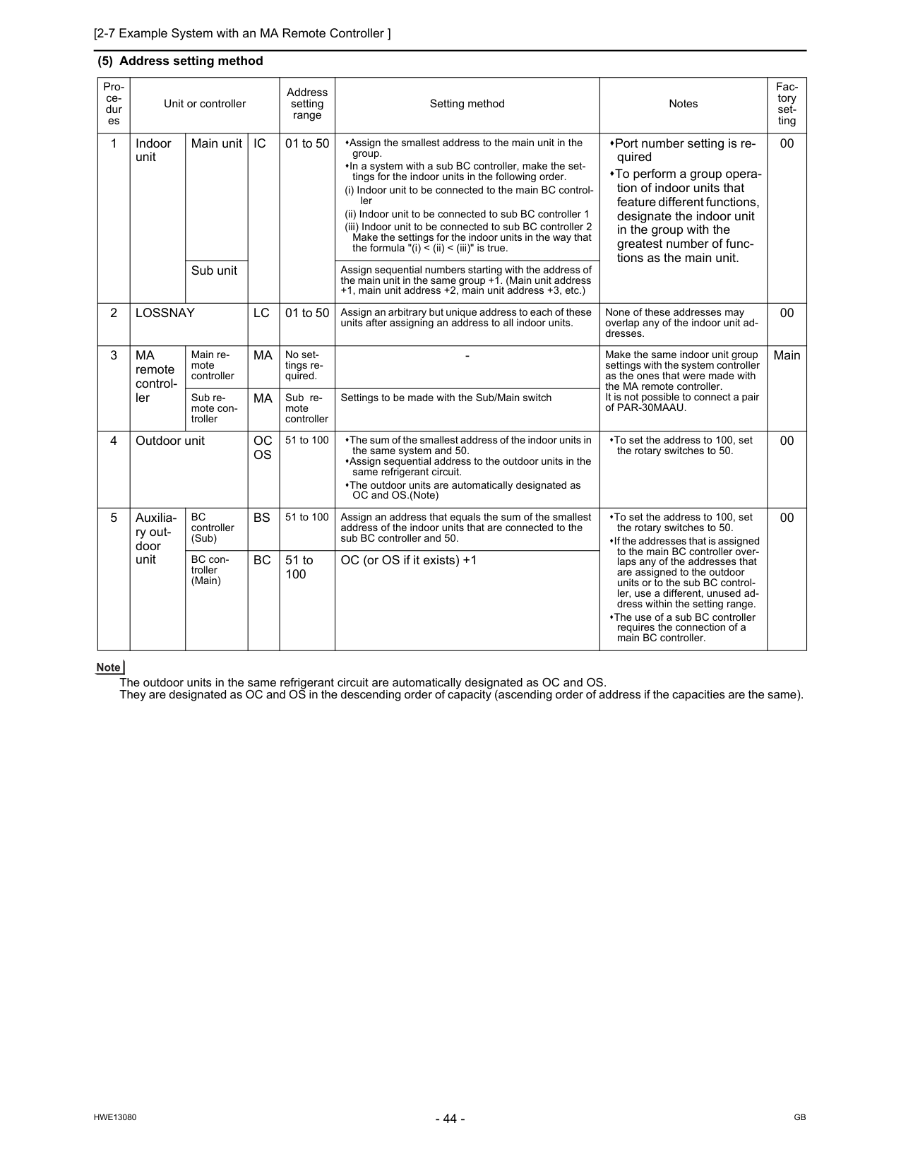
Gb
Hwe13080
(5) Address setting method The outdoor units in the same refrigerant circuit are automatically designated as OC and OS. They are designated as OC and OS in the descending order of capacity (ascending order of address if the capacities are the same). Pro- ce- dur es Unit or controller Address setting range Setting method Notes Fac- tory set- ting 1 Indoor unit Main unitIc
01 to 50 Assign the smallest address to the main unit in the group. In a system with a sub BC controller, make the set- tings for the indoor units in the following order. (i) Indoor unit to be connected to the main BC control- ler (ii) Indoor unit to be connected to sub BC controller 1 (iii) Indoor unit to be connected to sub BC controller 2 Make the settings for the indoor units in the way that the formula "(i) < (ii) < (iii)" is true. Port number setting is re- quired To perform a group opera- tion of indoor units that feature different functions, designate the indoor unit in the group with the greatest number of func- tions as the main unit. 00 Sub unit Assign sequential numbers starting with the address of the main unit in the same group +1. (Main unit address +1, main unit address +2, main unit address +3, etc.) 2Lossnay
Lc
01 to 50 Assign an arbitrary but unique address to each of these units after assigning an address to all indoor units. None of these addresses may overlap any of the indoor unit ad- dresses. 00 3Ma
remote control- ler Main re- mote controllerMa
No set- tings re- quired.Ma
Sub re- mote controller Settings to be made with the Sub/Main switch 4 Outdoor unitOc
Os
51 to 100 The sum of the smallest address of the indoor units in the same system and 50. Assign sequential address to the outdoor units in the same refrigerant circuit. The outdoor units are automatically designated as OC and OS.(Note) To set the address to 100, set the rotary switches to 50. 00 5 Auxilia- ry out- door unitBc
controller (Sub)Bs
51 to 100 Assign an address that equals the sum of the smallest address of the indoor units that are connected to the sub BC controller and 50. To set the address to 100, set the rotary switches to 50. If the addresses that is assigned to the main BC controller over- laps any of the addresses that are assigned to the outdoor units or to the sub BC control- ler, use a different, unused ad- dress within the setting range. The use of a sub BC controller requires the connection of a main BC controller. 00 BC con- troller (Main)Bc
51 to 100 OC (or OS if it exists) +1
[2-7 Example System with an MA Remote Controller ] 45
Hwe13080
Gb
2 Restrictions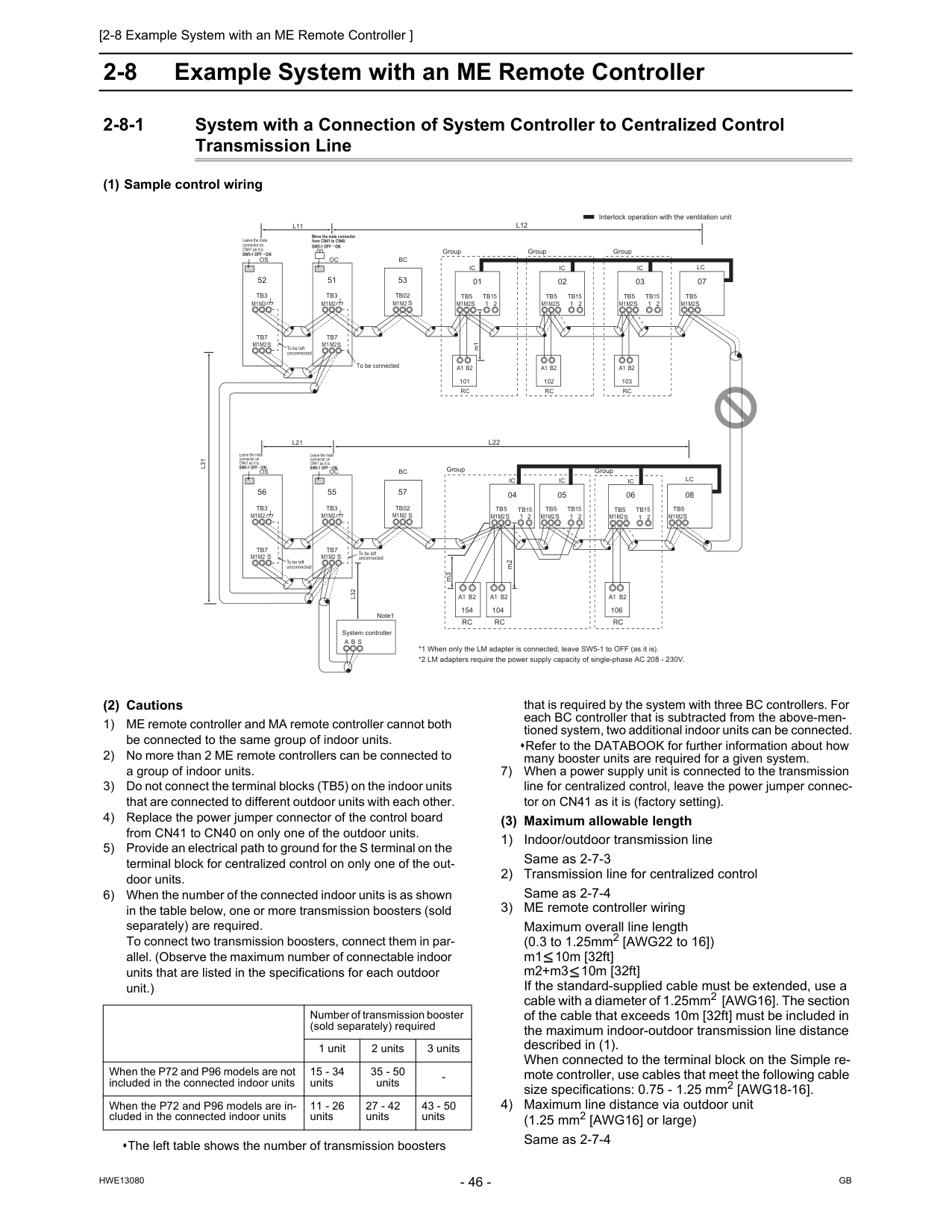
Gb
Hwe13080
2-8 Example System with an ME Remote Controller 2-8-1 System with a Connection of System Controller to Centralized Control Transmission Line (1) Sample control wiring (2) Cautions 1) ME remote controller and MA remote controller cannot both be connected to the same group of indoor units. 2) No more than 2 ME remote controllers can be connected to a group of indoor units. 3) Do not connect the terminal blocks (TB5) on the indoor units that are connected to different outdoor units with each other. 4) Replace the power jumper connector of the control board from CN41 to CN40 on only one of the outdoor units. 5) Provide an electrical path to ground for the S terminal on the terminal block for centralized control on only one of the out- door units. 6) When the number of the connected indoor units is as shown in the table below, one or more transmission boosters (sold separately) are required. To connect two transmission boosters, connect them in par- allel. (Observe the maximum number of connectable indoor units that are listed in the specifications for each outdoor unit.) The left table shows the number of transmission boosters that is required by the system with three BC controllers. For each BC controller that is subtracted from the above-men- tioned system, two additional indoor units can be connected. Refer to the DATABOOK for further information about how many booster units are required for a given system. 7) When a power supply unit is connected to the transmission line for centralized control, leave the power jumper connec- tor on CN41 as it is (factory setting). (3) Maximum allowable length 1) Indoor/outdoor transmission line Same as 2-7-3 2) Transmission line for centralized control Same as 2-7-4 3) ME remote controller wiring Maximum overall line length (0.3 to 1.25mm2 [AWG22 to 16]) m1 10m [32ft] m2+m3 10m [32ft] If the standard-supplied cable must be extended, use a cable with a diameter of 1.25mm2 [AWG16]. The section of the cable that exceeds 10m [32ft] must be included in the maximum indoor-outdoor transmission line distance described in (1). When connected to the terminal block on the Simple re- mote controller, use cables that meet the following cable size specifications: 0.75 - 1.25 mm2 [AWG18-16]. 4) Maximum line distance via outdoor unit (1.25 mm2 [AWG16] or large) Same as 2-7-4Ic
Tb5
S
Tb15
1 2 01Ic
Tb5
S
Tb15
1 2 02Lc
Tb5
S
07Ic
Tb5
S
1 2Tb15
Ic
Tb5
S
Tb15
1 2 05 04Lc
Tb5
S
08Ic
Tb5
S
Tb15
1 2 03Ic
Tb5
S
Tb15
1 2 06A1 B2
Rc
101A1 B2
Rc
102A1 B2
Rc
103 Group Group Group Group Group To be connectedM1M2
M1M2
M1M2
M1M2
M1M2
M1M2
M1M2
L31
A B S
L32
Oc
m1Tb3
Tb7
M1 M2S
51Os
Tb3
Tb7
M1M2
M1M2
M1M2
S
52Oc
Tb3
Tb7
S
55Os
Tb3
Tb7
S
56 To be left unconnected Interlock operation with the ventilation unit *1 When only the LM adapter is connected, leave SW5-1 to OFF (as it is). *2 LM adapters require the power supply capacity of single-phase AC 208 - 230V. System controller Note1Sw5-1 Off On
Leave the male connector on CN41 as it is.Sw5-1 Off On
Leave the male connector on CN41 as it is.Sw5-1 Off On
Move the male connector from CN41 to CN40.Sw5-1 Off On
Leave the male connector on CN41 as it is.M1M2
M1M2
M1M2
M1M2
M1M2
To be left unconnected To be left unconnected 104A1 B2
Rc
154A1 B2
Rc
m3 106A1 B2
Rc
m2S
Bc
Tb02
53S
Bc
Tb02
57L12
L11
L22
L21
M1M2
M1M2
Number of transmission booster (sold separately) required 1 unit 2 units 3 units When the P72 and P96 models are not included in the connected indoor units 15 - 34 units 35 - 50 units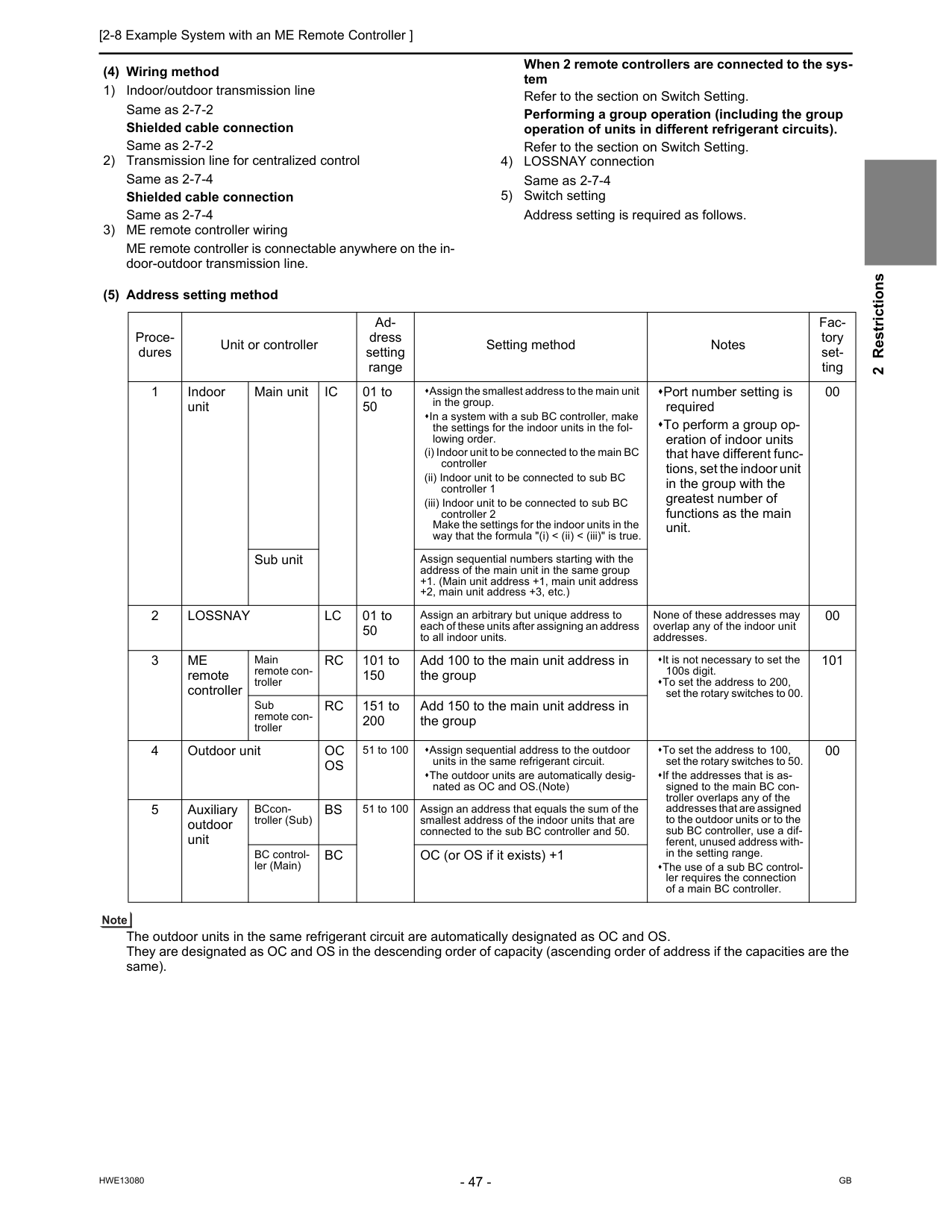
[2-8 Example System with an ME Remote Controller ] 47
Hwe13080
Gb
2 Restrictions (4) Wiring method 1) Indoor/outdoor transmission line Same as 2-7-2 Shielded cable connection Same as 2-7-2 2) Transmission line for centralized control Same as 2-7-4 Shielded cable connection Same as 2-7-4 3) ME remote controller wiring ME remote controller is connectable anywhere on the in- door-outdoor transmission line. When 2 remote controllers are connected to the sys- tem Refer to the section on Switch Setting. Performing a group operation (including the group operation of units in different refrigerant circuits). Refer to the section on Switch Setting. 4) LOSSNAY connection Same as 2-7-4 5) Switch setting Address setting is required as follows. (5) Address setting method The outdoor units in the same refrigerant circuit are automatically designated as OC and OS. They are designated as OC and OS in the descending order of capacity (ascending order of address if the capacities are the same). Proce- dures Unit or controller Ad- dress setting range Setting method Notes Fac- tory set- ting 1 Indoor unit Main unitIc
01 to 50 Assign the smallest address to the main unit in the group. In a system with a sub BC controller, make the settings for the indoor units in the fol- lowing order. (i) Indoor unit to be connected to the main BC controller (ii) Indoor unit to be connected to sub BC controller 1 (iii) Indoor unit to be connected to sub BC controller 2 Make the settings for the indoor units in the way that the formula "(i) < (ii) < (iii)" is true. Port number setting is required To perform a group op- eration of indoor units that have different func- tions, set the indoor unit in the group with the greatest number of functions as the main unit. 00 Sub unit Assign sequential numbers starting with the address of the main unit in the same group +1. (Main unit address +1, main unit address +2, main unit address +3, etc.) 2Lossnay
Lc
01 to 50 Assign an arbitrary but unique address to each of these units after assigning an address to all indoor units. None of these addresses may overlap any of the indoor unit addresses. 00 3Me
remote controller Main remote con- trollerRc
101 to 150 Add 100 to the main unit address in the group It is not necessary to set the 100s digit. To set the address to 200, set the rotary switches to 00. 101 Sub remote con- trollerRc
151 to 200 Add 150 to the main unit address in the group 4 Outdoor unitOc
Os
51 to 100 Assign sequential address to the outdoor units in the same refrigerant circuit. The outdoor units are automatically desig- nated as OC and OS.(Note) To set the address to 100, set the rotary switches to 50. If the addresses that is as- signed to the main BC con- troller overlaps any of the addresses that are assigned to the outdoor units or to the sub BC controller, use a dif- ferent, unused address with- in the setting range. The use of a sub BC control- ler requires the connection of a main BC controller. 00 5 Auxiliary outdoor unit BCcon- troller (Sub)Bs
51 to 100 Assign an address that equals the sum of the smallest address of the indoor units that are connected to the sub BC controller and 50. BC control- ler (Main)Bc
OC (or OS if it exists) +1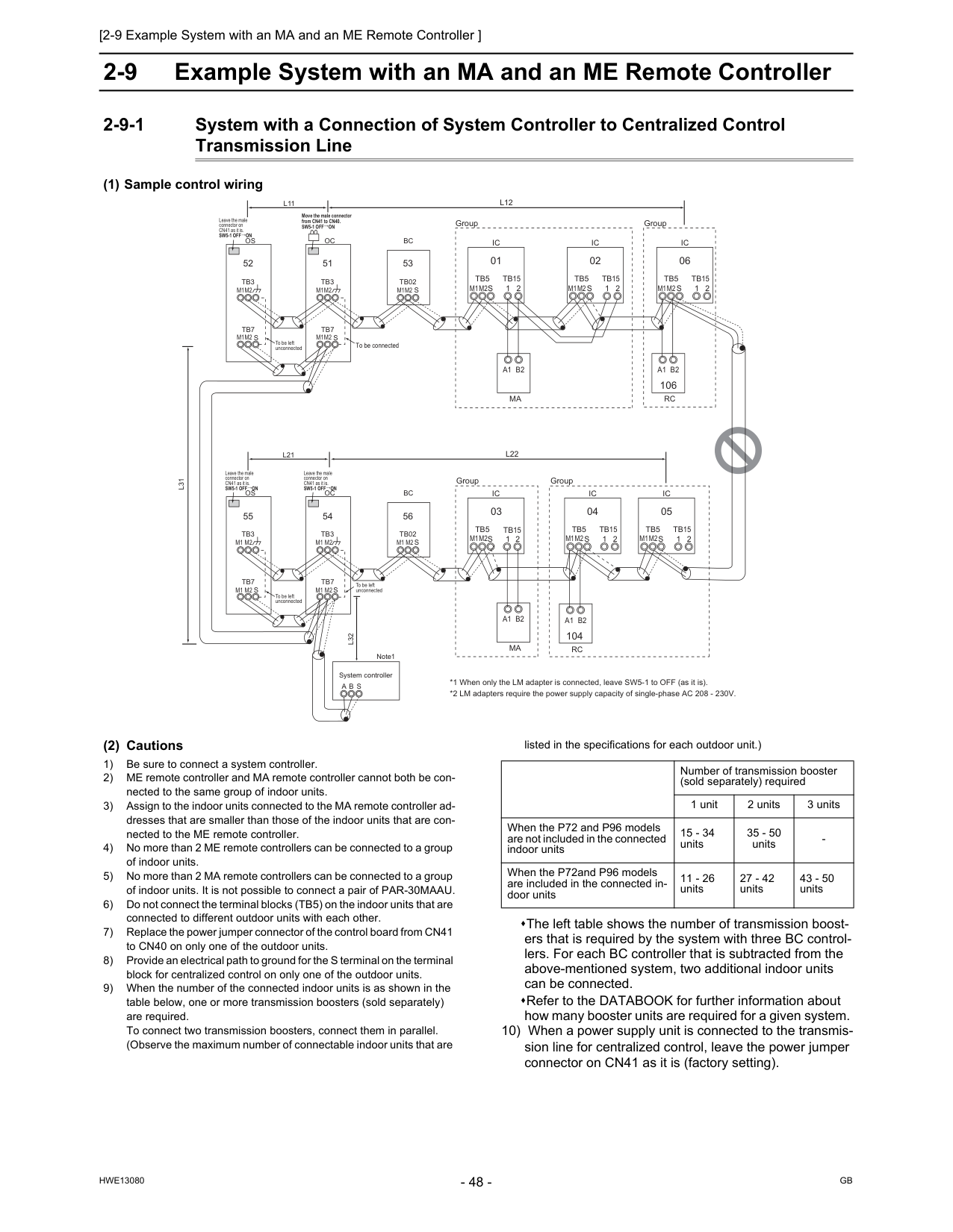
Gb
Hwe13080
2-9 Example System with an MA and an ME Remote Controller 2-9-1 System with a Connection of System Controller to Centralized Control Transmission Line (1) Sample control wiring (2) Cautions 1) Be sure to connect a system controller. 2) ME remote controller and MA remote controller cannot both be con- nected to the same group of indoor units. 3) Assign to the indoor units connected to the MA remote controller ad- dresses that are smaller than those of the indoor units that are con- nected to the ME remote controller. 4) No more than 2 ME remote controllers can be connected to a group of indoor units. 5) No more than 2 MA remote controllers can be connected to a group of indoor units. It is not possible to connect a pair of PAR-30MAAU. 6) Do not connect the terminal blocks (TB5) on the indoor units that are connected to different outdoor units with each other. 7) Replace the power jumper connector of the control board from CN41 to CN40 on only one of the outdoor units. 8) Provide an electrical path to ground for the S terminal on the terminal block for centralized control on only one of the outdoor units. 9) When the number of the connected indoor units is as shown in the table below, one or more transmission boosters (sold separately) are required. To connect two transmission boosters, connect them in parallel. (Observe the maximum number of connectable indoor units that are listed in the specifications for each outdoor unit.) The left table shows the number of transmission boost- ers that is required by the system with three BC control- lers. For each BC controller that is subtracted from the above-mentioned system, two additional indoor units can be connected. Refer to the DATABOOK for further information about how many booster units are required for a given system. 10) When a power supply unit is connected to the transmis- sion line for centralized control, leave the power jumper connector on CN41 as it is (factory setting).Ic
Tb5
S
Tb15
1 2 01Ic
Tb5
S
Tb15
1 2 02Ic
Tb5
S
Tb15
1 2 06 106Ic
Tb5
S
Tb15
1 2 05A1 B2
Ma
A1 B2
Rc
A1 B2
Ma
Ic
Tb5
S
1 2Tb15
Ic
Tb5
S
Tb15
1 2 04 03 104A1 B2
Rc
Oc
Tb3
Tb7
S
51Os
Tb3
Tb7
S
52Oc
Tb3
Tb7
S
54Os
Tb3
Tb7
S
55L31
A B S
L32
Sw5-1 Off On
Leave the male connector on CN41 as it is.Sw5-1 Off On
Leave the male connector on CN41 as it is. To be left unconnected To be left unconnected To be left unconnected To be connected System controller Note1 *1 When only the LM adapter is connected, leave SW5-1 to OFF (as it is). *2 LM adapters require the power supply capacity of single-phase AC 208 - 230V.M1M2
M1M2
M1M2
M1M2
M1M2
M1M2
M1M2
M1M2
M1M2
M1M2
M1 M2
M1 M2
M1 M2
M1 M2
M1 M2
S
Bc
Tb02
53S
Bc
Tb02
56L22
L21
L12
L11
Sw5-1 Off On
Leave the male connector on CN41 as it is.Sw5-1 Off On
Move the male connector from CN41 to CN40. Group Group Group GroupM1M2
Number of transmission booster (sold separately) required 1 unit 2 units 3 units When the P72 and P96 models are not included in the connected indoor units 15 - 34 units 35 - 50 units
[2-9 Example System with an MA and an ME Remote Controller ] 49
Hwe13080
Gb
2 Restrictions (3) Maximum allowable length 1) Indoor/outdoor transmission line Same as 2-7-3 2) Transmission line for centralized control Same as 2-7-4 3) MA remote controller wiring Same as 2-7-1 4) ME remote controller wiring Same as 2-8 5) Maximum line distance via outdoor unit (1.25 mm2 [AWG16] or larger) Same as 2-7-4 (4) Wiring method 1) Indoor/outdoor transmission line Same as 2-7-2 Shielded cable connection Same as 2-7-2 2) Transmission line for centralized control Same as 2-7-4 Shielded cable connection Same as 2-7-4 3) MA remote controller wiring (When 2 remote controllers are connected to the system) (Group operation of indoor units) Same as 2-7-1 4) ME remote controller wiring (When 2 remote controllers are connected to the system) (Group operation of indoor units) Same as 2-8 5) LOSSNAY connection Same as 2-7-4 6) Switch setting Address setting is required as follows.
Gb
Hwe13080
(5) Address setting method The outdoor units in the same refrigerant circuit are automatically designated as OC and OS. They are designated as OC and OS in the descending order of capacity (ascending order of address if the capacities are the same). Pro- ce- dure s Unit or controller Ad- dress set- ting range Setting method Notes Facto- ry set- ting 1 Opera- tion with the MA re- mote controller In- door unit Main unitIc
01 to 50 Assign the smallest address to the main unit in the group. In a system with a sub BC con- troller, make the settings for the indoor units in the following or- der. (i) Indoor unit to be connected to the main BC controller (ii) Indoor unit to be connected to sub BC controller 1 (iii) Indoor unit to be connected to sub BC controller 2 Make the settings for the indoor units in the way that the formula "(i) < (ii) < (iii)" is true. Assign an address smaller than that of the indoor unit that is connected to the ME remote controller. Enter the same indoor unit group set- tings on the system controller as the ones that were entered on the MA re- mote controller. To perform a group operation of indoor units that have different functions, des- ignate the indoor unit in the group with the greatest number of functions as the main unit. Port number setting is required. 00 Sub unitIc
01 to 50 Assign sequential numbers start- ing with the address of the main unit in the same group +1. (Main unit address +1, main unit address +2, main unit address +3, etc.)Ma
re- mote con- troller Main re- mote control- lerMa
No set- tings re- quired.Ma
Sub remote control- ler Settings to be made according to the remote controller func- tion selection 2 Opera- tion with the ME re- mote controller In- door unit Main unitIc
01 to 50 Assign the smallest address to the main unit in the group. Assign an address higher than those of the indoor units that are connected to the MA remote controller. Make the initial settings for the indoor unit group settings via the system con- troller. To perform a group operation of indoor units that have different functions, des- ignate the indoor unit in the group with the greatest number of functions as the main unit. Port number setting is required. Addresses that are assigned to the in- door units that are connected to the sub BC controller should be higher than the addresses that are assigned to the in- door units that are connected to the main BC controller. 00 Sub unitIc
01 to 50 Assign sequential numbers starting with the address of the main unit in the same group +1. (Main unit address +1, main unit address +2, main unit address +3, etc.)Me
re- mote con- troller Main re- mote control- lerRc
101 to 150 Add 100 to the main unit ad- dress in the group. It is not necessary to set the 100s digit. To set the address to 200, set it toRc
151 to 200 Add 150 to the main unit ad- dress in the group. 3Lossnay
Lc
01 to 50 Assign an arbitrary but unique address to each of these units after assigning an address to all indoor units. None of these addresses may over- lap any of the indoor unit addresses. 00 4 Outdoor unitOc
Os
51 to 100 Assign sequential address to the outdoor units in the same refrig- erant circuit. The outdoor units are automati- cally designated as OC and OS.(Note) To set the address to 100, set it to 50. If the addresses that is assigned to the main BC controller overlaps any of the addresses that are assigned to the out- door units or to the sub BC controller, use a different, unused address within the setting range. The use of a sub BC controller requires the connection of a main BC controller. 00 5 Auxiliary outdoor unit BCcontroller (Sub)Bs
51 to 100 Assign an address that equals the sum of the smallest address of the indoor units that are connected to the sub BC controller and 50. BC controller (Main)Bc
OC (or OS if it exists) +1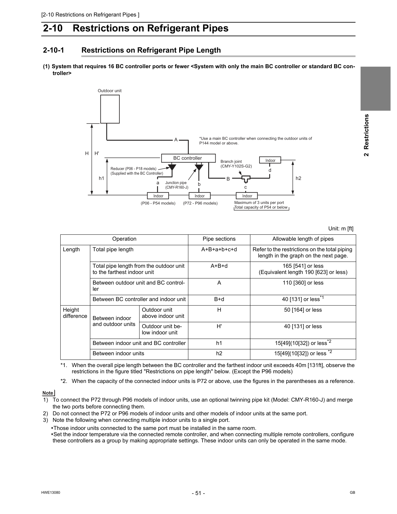
[2-10 Restrictions on Refrigerant Pipes ]
Hwe13080
Gb
2 Restrictions 2-10 Restrictions on Refrigerant Pipes 2-10-1 Restrictions on Refrigerant Pipe Length (1) System that requires 16 BC controller ports or fewerH
H'
h1A
h2 Outdoor unit BC controller Reducer (P06 - P18 models) (Supplied with the BC Controller)B
d c Junction pipe(Cmy-R160-J)
*Use a main BC controller when connecting the outdoor units of P144 model or above. Branch joint(Cmy-Y102S-G2)
Indoor Indoor Indoor Indoor (P06 - P54 models) (P72 - P96 models) Maximum of 3 units per port Total capacity of P54 or below Unit: m [ft] Operation Pipe sections Allowable length of pipes Length Total pipe length A+B+a+b+c+d Refer to the restrictions on the total piping length in the graph on the next page. Total pipe length from the outdoor unit to the farthest indoor unit A+B+d 165 [541] or less (Equivalent length 190 [623] or less) Between outdoor unit and BC control- lerA
110 [360] or less Between BC controller and indoor unit B+d 40 [131] or less*1 Height difference Between indoor and outdoor units Outdoor unit above indoor unitH
50 [164] or less Outdoor unit be- low indoor unitH'
40 [131] or less Between indoor unit and BC controller h1 15[49](10[32]) or less*2 Between indoor units h2 15[49](10[32]) or less *2 *1. When the overall pipe length between the BC controller and the farthest indoor unit exceeds 40m [131ft], observe the restrictions in the figure titled "Restrictions on pipe length" below. (Except the P96 models) *2. When the capacity of the connected indoor units is P72 or above, use the figures in the parentheses as a reference.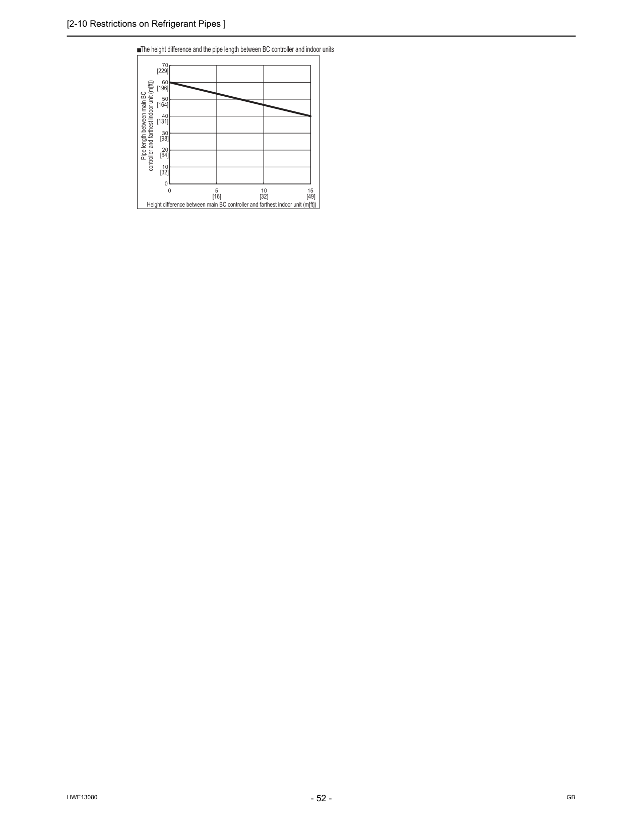
[2-10 Restrictions on Refrigerant Pipes ]
Hwe13080
Gb
0 10 20 30 40 50 60 70 0 5 10 15 Pipe length between main BC controller and farthest indoor unit (m[ft]) Height difference between main BC controller and farthest indoor unit (m[ft]) The height difference and the pipe length between BC controller and indoor units [32] [16] [32] [49] [64] [98] [131] [164] [196] [229]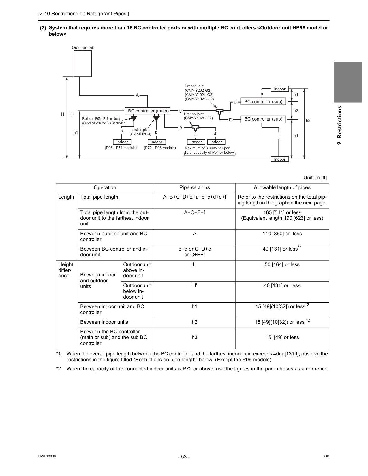
[2-10 Restrictions on Refrigerant Pipes ]
Hwe13080
Gb
2 Restrictions (2) System that requires more than 16 BC controller ports or with multiple BC controllersA
110 [360] or less Between BC controller and in- door unit B+d or C+D+e or C+E+f 40 [131] or less*1 *1. When the overall pipe length between the BC controller and the farthest indoor unit exceeds 40m [131ft], observe the restrictions in the figure titled "Restrictions on pipe length" below. (Except the P96 models) Height differ- ence Between indoor and outdoor units Outdoor unit above in- door unitH
50 [164] or less Outdoor unit below in- door unitH'
40 [131] or less Between indoor unit and BC controller h1 15 [49](10[32]) or less*2 *2. When the capacity of the connected indoor units is P72 or above, use the figures in the parentheses as a reference. Between indoor units h2 15 [49](10[32]) or less *2 Between the BC controller (main or sub) and the sub BC controller h3 15 [49] or less Branch joint(Cmy-Y202-G2)
(Cmy-Y102L-G2)
(Cmy-Y102S-G2)
Branch joint(Cmy-Y102S-G2)
aC
bH
H'
h1 h1B
c d f h3D
E
A
e h1 h2 Outdoor unit BC controller (main) BC controller (sub) BC controller (sub) Indoor Indoor Indoor Indoor Indoor Indoor Reducer (P06 - P18 models) (Supplied with the BC Controller) (P06 - P54 models) (P72 - P96 models) Maximum of 3 units per port Total capacity of P54 or below Junction pipe(Cmy-R160-J)
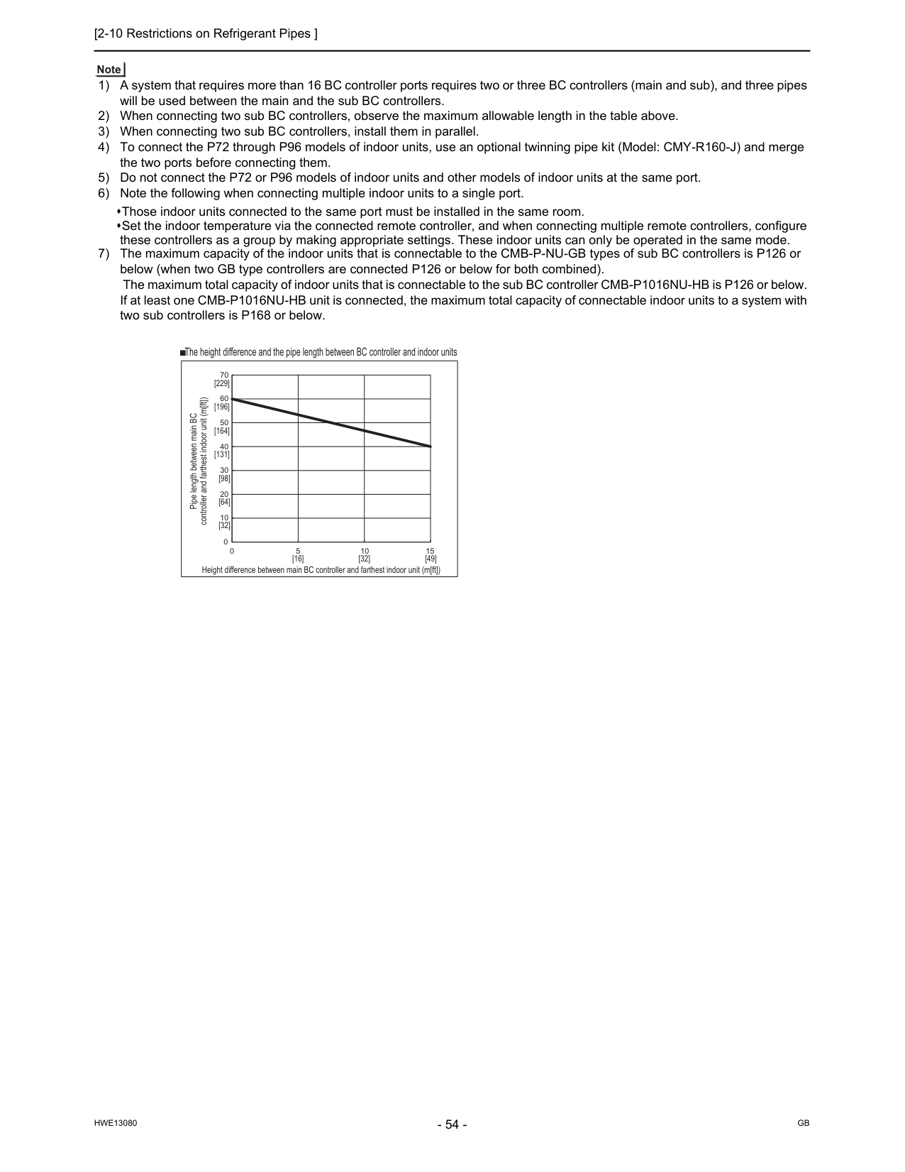
[2-10 Restrictions on Refrigerant Pipes ]
Hwe13080
Gb
1) A system that requires more than 16 BC controller ports requires two or three BC controllers (main and sub), and three pipes will be used between the main and the sub BC controllers. 2) When connecting two sub BC controllers, observe the maximum allowable length in the table above. 3) When connecting two sub BC controllers, install them in parallel. 4) To connect the P72 through P96 models of indoor units, use an optional twinning pipe kit (Model: CMY-R160-J) and merge the two ports before connecting them. 5) Do not connect the P72 or P96 models of indoor units and other models of indoor units at the same port. 6) Note the following when connecting multiple indoor units to a single port. Those indoor units connected to the same port must be installed in the same room. Set the indoor temperature via the connected remote controller, and when connecting multiple remote controllers, configure these controllers as a group by making appropriate settings. These indoor units can only be operated in the same mode. 7) The maximum capacity of the indoor units that is connectable to the CMB-P-NU-GB types of sub BC controllers is P126 or below (when two GB type controllers are connected P126 or below for both combined). The maximum total capacity of indoor units that is connectable to the sub BC controller CMB-P1016NU-HB is P126 or below. If at least one CMB-P1016NU-HB unit is connected, the maximum total capacity of connectable indoor units to a system with two sub controllers is P168 or below. 0 10 20 30 40 50 60 70 0 5 10 15 Pipe length between main BC controller and farthest indoor unit (m[ft]) Height difference between main BC controller and farthest indoor unit (m[ft]) The height difference and the pipe length between BC controller and indoor units [32] [16] [32] [49] [64] [98] [131] [164] [196] [229]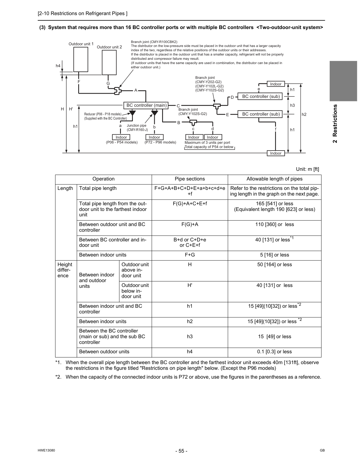
[2-10 Restrictions on Refrigerant Pipes ]
Hwe13080
Gb
2 Restrictions (3) System that requires more than 16 BC controller ports or with multiple BC controllersF(G)+A
110 [360] or less Between BC controller and in- door unit B+d or C+D+e or C+E+f 40 [131] or less*1 *1. When the overall pipe length between the BC controller and the farthest indoor unit exceeds 40m [131ft], observe the restrictions in the figure titled "Restrictions on pipe length" below. (Except the P96 models) Between indoor unitsF+G
5 [16] or less Height differ- ence Between indoor and outdoor units Outdoor unit above in- door unitH
50 [164] or less Outdoor unit below in- door unitH'
40 [131] or less Between indoor unit and BC controller h1 15 [49](10[32]) or less*2 *2. When the capacity of the connected indoor units is P72 or above, use the figures in the parentheses as a reference. Between indoor units h2 15 [49](10[32]) or less *2 Between the BC controller (main or sub) and the sub BC controller h3 15 [49] or less Between outdoor units h4 0.1 [0.3] or less h1 h3 h1 h2 fD
E
e Branch joint (CMY-R100CBK2) The distributor on the low-pressure side must be placed in the outdoor unit that has a larger capacity index of the two, regardless of the relative positions of the outdoor units or their addresses. If the distributor is placed in the outdoor unit that has a smaller capacity, refrigerant will not be properly distributed and compressor failure may result. (If outdoor units that have the same capacity are used in combination, the distributor can be placed in either outdoor unit.) aC
bB
c dA
G
F
h4 Outdoor unit 1 Outdoor unit 2H
H'
h1 BC controller (main) Indoor Indoor Indoor Indoor Indoor Indoor BC controller (sub) BC controller (sub) Branch joint(Cmy-Y202-G2)
(Cmy-Y102L-G2)
(Cmy-Y102S-G2)
Branch joint(Cmy-Y102S-G2)
(P06 - P54 models) (P72 - P96 models) Maximum of 3 units per port Total capacity of P54 or below Reducer (P06 - P18 models) (Supplied with the BC Controller) Junction pipe(Cmy-R160-J)
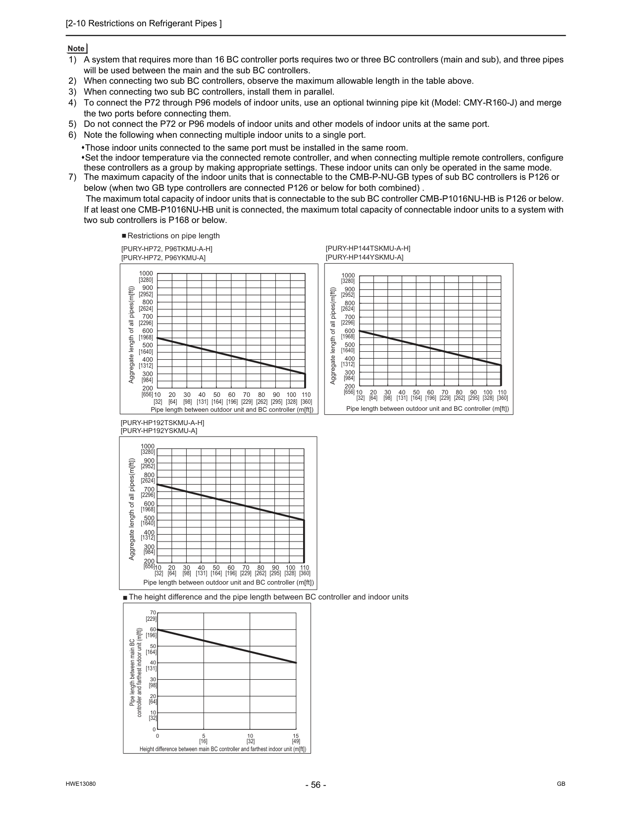
[2-10 Restrictions on Refrigerant Pipes ]
Hwe13080
Gb
1) A system that requires more than 16 BC controller ports requires two or three BC controllers (main and sub), and three pipes will be used between the main and the sub BC controllers. 2) When connecting two sub BC controllers, observe the maximum allowable length in the table above. 3) When connecting two sub BC controllers, install them in parallel. 4) To connect the P72 through P96 models of indoor units, use an optional twinning pipe kit (Model: CMY-R160-J) and merge the two ports before connecting them. 5) Do not connect the P72 or P96 models of indoor units and other models of indoor units at the same port. 6) Note the following when connecting multiple indoor units to a single port. Those indoor units connected to the same port must be installed in the same room. Set the indoor temperature via the connected remote controller, and when connecting multiple remote controllers, configure these controllers as a group by making appropriate settings. These indoor units can only be operated in the same mode. 7) The maximum capacity of the indoor units that is connectable to the CMB-P-NU-GB types of sub BC controllers is P126 or below (when two GB type controllers are connected P126 or below for both combined) . The maximum total capacity of indoor units that is connectable to the sub BC controller CMB-P1016NU-HB is P126 or below. If at least one CMB-P1016NU-HB unit is connected, the maximum total capacity of connectable indoor units to a system with two sub controllers is P168 or below. 0 10 20 30 40 50 60 70 0 5 10 15[Pury-Hp192Tskmu-A-H]
[Pury-Hp192Yskmu-A]
The height difference and the pipe length between BC controller and indoor units Restrictions on pipe length Aggregate length of all pipes(m[ft]) Pipe length between main BC controller and farthest indoor unit (m[ft]) Height difference between main BC controller and farthest indoor unit (m[ft]) [32] [16] [32] [49] [64] [98] [131] [164] [196] [229] 110 1000 900 800 700 600 500 400 300 200 10 20 30 40 50 60 70 80 90 100 Pipe length between outdoor unit and BC controller (m[ft]) [32] [64] [98] [131] [164] [196] [229] [262] [295] [328] [360] [3280] [2952] [2624] [2296] [1968] [1640] [1312] [984] [656] 1000 900 800 700 600 500 400 300 200 10 20 30 40 50 60 70 80 90 100 110 Aggregate length of all pipes(m[ft]) Pipe length between outdoor unit and BC controller (m[ft]) [32] [64] [98] [131] [164] [196] [229] [262] [295] [328] [360] [3280] [2952] [2624] [2296] [1968] [1640] [1312] [984] [656] 1000 900 800 700 600 500 400 300 200 10 20 30 40 50 60 70 80 90 100 110 Aggregate length of all pipes(m[ft]) Pipe length between outdoor unit and BC controller (m[ft]) [32] [64] [98] [131] [164] [196] [229] [262] [295] [328] [360] [3280] [2952] [2624] [2296] [1968] [1640] [1312] [984] [656][Pury-Hp72, P96Tkmu-A-H]
[Pury-Hp72, P96Ykmu-A]
[Pury-Hp144Tskmu-A-H]
[Pury-Hp144Yskmu-A]
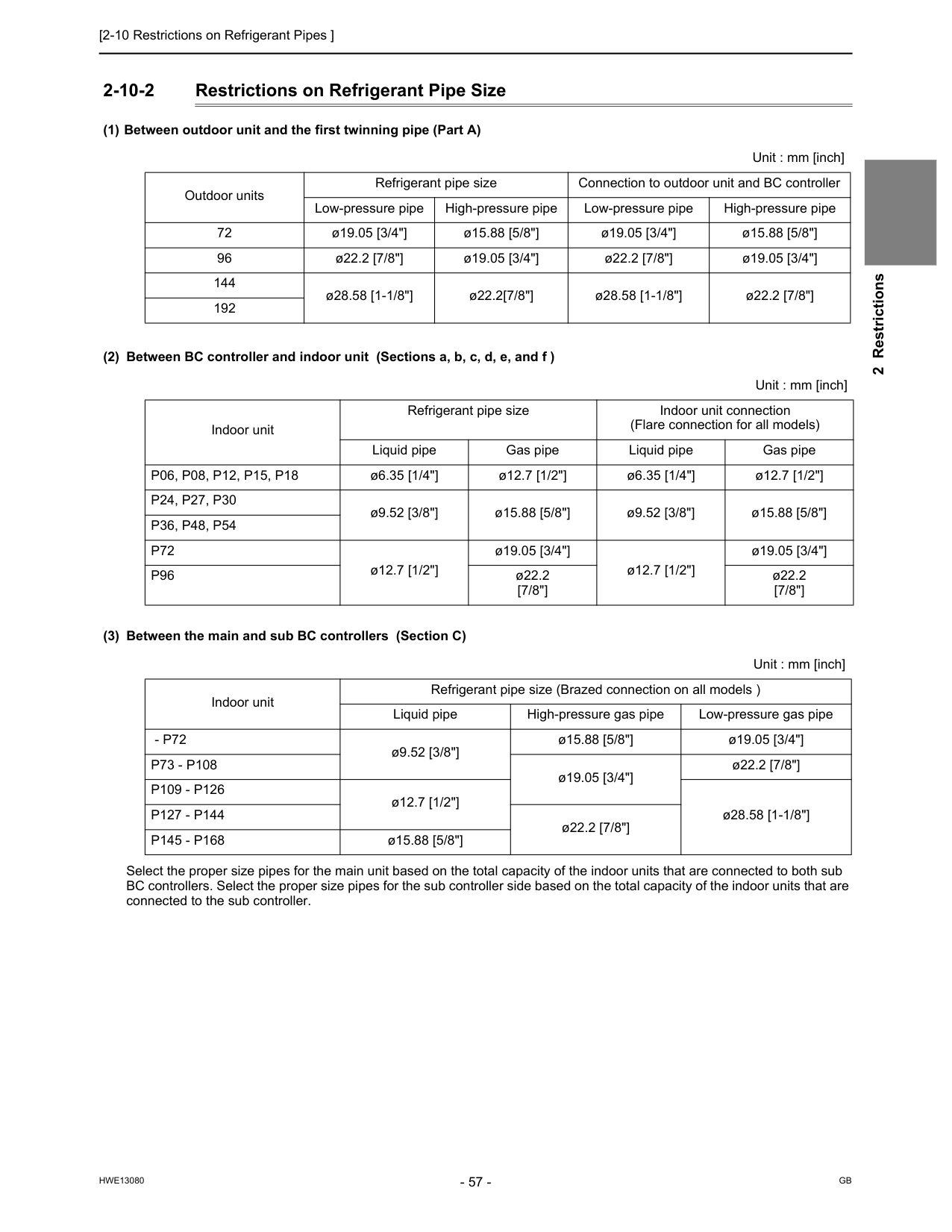
[2-10 Restrictions on Refrigerant Pipes ]
Hwe13080
Gb
2 Restrictions 2-10-2 Restrictions on Refrigerant Pipe Size (1) Between outdoor unit and the first twinning pipe (Part A) (2) Between BC controller and indoor unit (Sections a, b, c, d, e, and f ) (3) Between the main and sub BC controllers (Section C) Select the proper size pipes for the main unit based on the total capacity of the indoor units that are connected to both sub BC controllers. Select the proper size pipes for the sub controller side based on the total capacity of the indoor units that are connected to the sub controller. Unit : mm [inch] Outdoor units Refrigerant pipe size Connection to outdoor unit and BC controller Low-pressure pipe High-pressure pipe Low-pressure pipe High-pressure pipe 72 ø19.05 [3/4"] ø15.88 [5/8"] ø19.05 [3/4"] ø15.88 [5/8"] 96 ø22.2 [7/8"] ø19.05 [3/4"] ø22.2 [7/8"] ø19.05 [3/4"] 144 ø28.58 [1-1/8"] ø22.2[7/8"] ø28.58 [1-1/8"] ø22.2 [7/8"] 192 Unit : mm [inch] Indoor unit Refrigerant pipe size Indoor unit connection (Flare connection for all models) Liquid pipe Gas pipe Liquid pipe Gas pipeP06, P08, P12, P15, P18
ø6.35 [1/4"] ø12.7 [1/2"] ø6.35 [1/4"] ø12.7 [1/2"]P24, P27, P30
ø9.52 [3/8"] ø15.88 [5/8"] ø9.52 [3/8"] ø15.88 [5/8"]P36, P48, P54
P72
ø12.7 [1/2"] ø19.05 [3/4"] ø12.7 [1/2"] ø19.05 [3/4"]P96
ø22.2 [7/8"] ø22.2 [7/8"] Unit : mm [inch] Indoor unit Refrigerant pipe size (Brazed connection on all models ) Liquid pipe High-pressure gas pipe Low-pressure gas pipe- P72
ø9.52 [3/8"] ø15.88 [5/8"] ø19.05 [3/4"]P73 - P108
ø19.05 [3/4"] ø22.2 [7/8"]P109 - P126
ø12.7 [1/2"] ø28.58 [1-1/8"]P127 - P144
ø22.2 [7/8"]P145 - P168
ø15.88 [5/8"]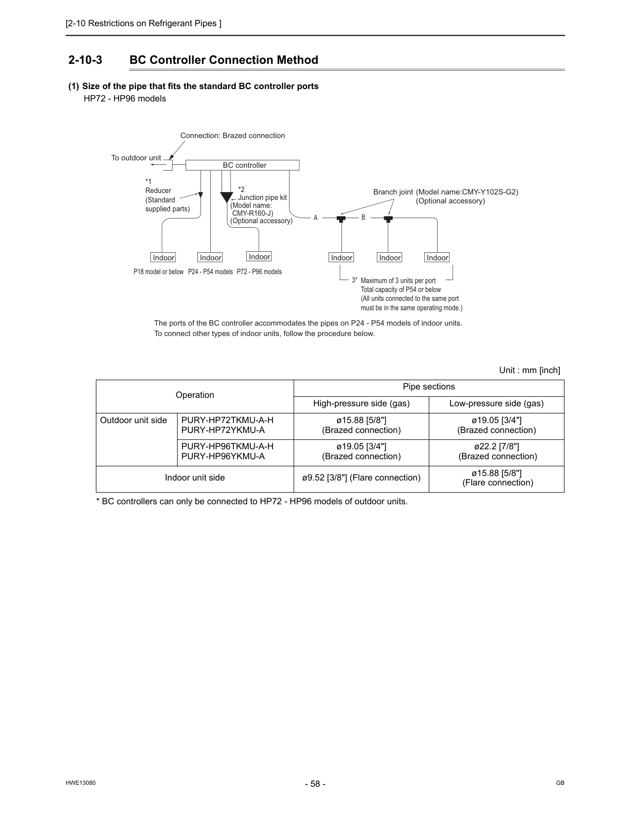
[2-10 Restrictions on Refrigerant Pipes ]
Hwe13080
Gb
2-10-3 BC Controller Connection Method (1) Size of the pipe that fits the standard BC controller ports HP72 - HP96 modelsPury-Hp72Tkmu-A-H
Pury-Hp72Ykmu-A
ø15.88 [5/8"] (Brazed connection) ø19.05 [3/4"] (Brazed connection)Pury-Hp96Tkmu-A-H
Pury-Hp96Ykmu-A
ø19.05 [3/4"] (Brazed connection) ø22.2 [7/8"] (Brazed connection) Indoor unit side ø9.52 [3/8"] (Flare connection) ø15.88 [5/8"] (Flare connection) Indoor Indoor Indoor Indoor Indoor Indoor BC controller Maximum of 3 units per port Total capacity of P54 or below (All units connected to the same port must be in the same operating mode.) Branch joint (Model name:CMY-Y102S-G2)(Optional accessory) *2 Junction pipe kit (Model name:
Cmy-R160-J)
(Optional accessory) P18 model or below P24 - P54 models P72 - P96 models The ports of the BC controller accommodates the pipes on P24 - P54 models of indoor units. To connect other types of indoor units, follow the procedure below. 3*A
B
*1 Reducer (Standard supplied parts) To outdoor unit Connection: Brazed connection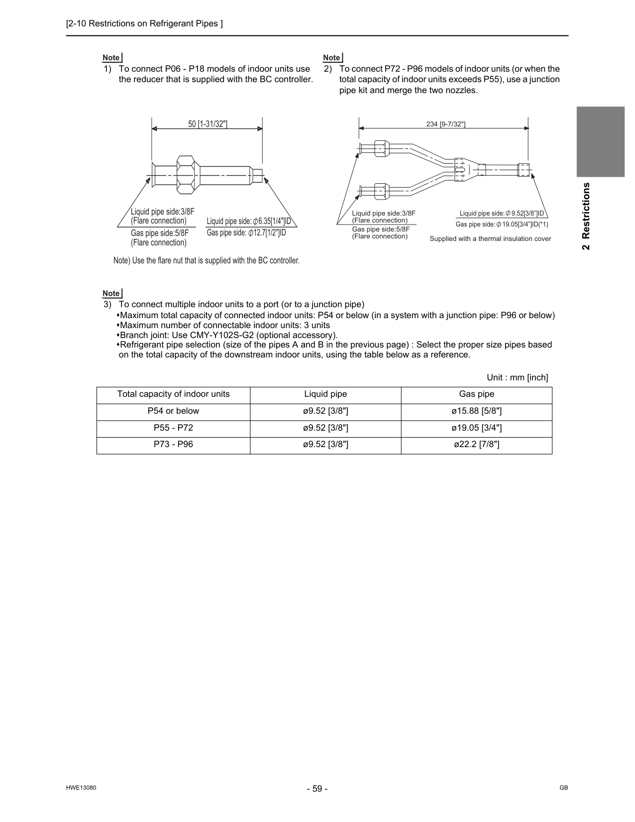
[2-10 Restrictions on Refrigerant Pipes ]
Hwe13080
Gb
2 Restrictions 1) To connect P06 - P18 models of indoor units use the reducer that is supplied with the BC controller. 2) To connect P72 - P96 models of indoor units (or when the total capacity of indoor units exceeds P55), use a junction pipe kit and merge the two nozzles. 3) To connect multiple indoor units to a port (or to a junction pipe) Maximum total capacity of connected indoor units: P54 or below (in a system with a junction pipe: P96 or below) Maximum number of connectable indoor units: 3 units Branch joint: Use CMY-Y102S-G2 (optional accessory). Refrigerant pipe selection (size of the pipes A and B in the previous page) : Select the proper size pipes based on the total capacity of the downstream indoor units, using the table below as a reference. Unit : mm [inch] Total capacity of indoor units Liquid pipe Gas pipe P54 or below ø9.52 [3/8"] ø15.88 [5/8"]P55 - P72
ø9.52 [3/8"] ø19.05 [3/4"]P73 - P96
ø9.52 [3/8"] ø22.2 [7/8"] Liquid pipe side: 6.35[1/4"]ID Gas pipe side: 12.7[1/2"]ID Liquid pipe side:3/8F (Flare connection) Gas pipe side:5/8F (Flare connection) Note) Use the flare nut that is supplied with the BC controller. 50 [1-31/32"] Liquid pipe side: 9.52[3/8”]ID Gas pipe side: 19.05[3/4”]ID(*1) 234 [9-7/32"] Supplied with a thermal insulation cover Liquid pipe side:3/8F (Flare connection) Gas pipe side:5/8F (Flare connection)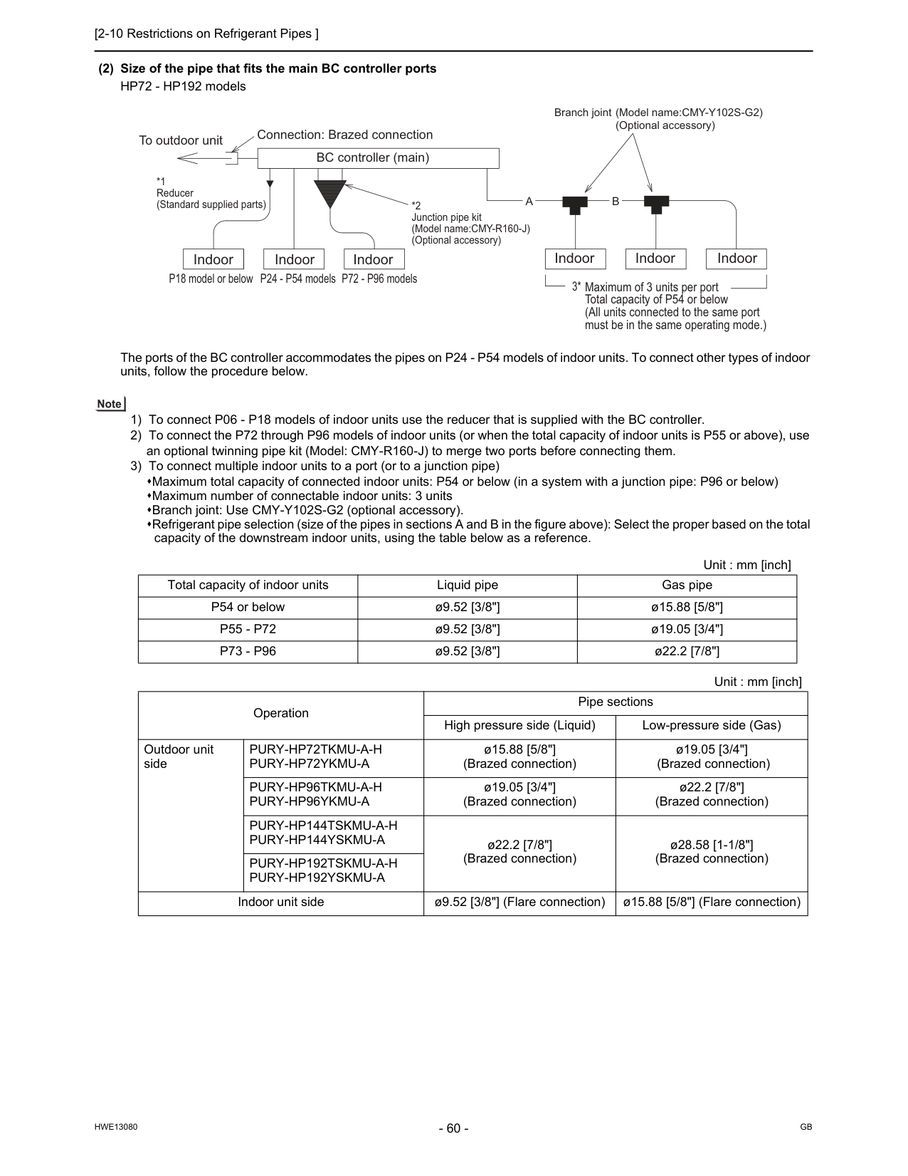
[2-10 Restrictions on Refrigerant Pipes ]
Hwe13080
Gb
(2) Size of the pipe that fits the main BC controller ports HP72 - HP192 models The ports of the BC controller accommodates the pipes on P24 - P54 models of indoor units. To connect other types of indoor units, follow the procedure below. 1) To connect P06 - P18 models of indoor units use the reducer that is supplied with the BC controller. 2) To connect the P72 through P96 models of indoor units (or when the total capacity of indoor units is P55 or above), use an optional twinning pipe kit (Model: CMY-R160-J) to merge two ports before connecting them. 3) To connect multiple indoor units to a port (or to a junction pipe) Maximum total capacity of connected indoor units: P54 or below (in a system with a junction pipe: P96 or below) Maximum number of connectable indoor units: 3 units Branch joint: Use CMY-Y102S-G2 (optional accessory). Refrigerant pipe selection (size of the pipes in sections A and B in the figure above): Select the proper based on the total capacity of the downstream indoor units, using the table below as a reference. Unit : mm [inch] Total capacity of indoor units Liquid pipe Gas pipe P54 or below ø9.52 [3/8"] ø15.88 [5/8"]P55 - P72
ø9.52 [3/8"] ø19.05 [3/4"]P73 - P96
ø9.52 [3/8"] ø22.2 [7/8"] Unit : mm [inch] Operation Pipe sections High pressure side (Liquid) Low-pressure side (Gas) Outdoor unit sidePury-Hp72Tkmu-A-H
Pury-Hp72Ykmu-A
ø15.88 [5/8"] (Brazed connection) ø19.05 [3/4"] (Brazed connection)Pury-Hp96Tkmu-A-H
Pury-Hp96Ykmu-A
ø19.05 [3/4"] (Brazed connection) ø22.2 [7/8"] (Brazed connection)Pury-Hp144Tskmu-A-H
Pury-Hp144Yskmu-A
ø22.2 [7/8"] (Brazed connection) ø28.58 [1-1/8"] (Brazed connection)Pury-Hp192Tskmu-A-H
Pury-Hp192Yskmu-A
Indoor unit side ø9.52 [3/8"] (Flare connection) ø15.88 [5/8"] (Flare connection)A
B
Indoor Indoor Indoor P18 model or below P24 - P54 models P72 - P96 models *2 Junction pipe kit (Model name:CMY-R160-J) (Optional accessory) BC controller (main) To outdoor unit Connection: Brazed connection *1 Reducer (Standard supplied parts) Maximum of 3 units per port Total capacity of P54 or below (All units connected to the same port must be in the same operating mode.) 3* Indoor Indoor Indoor Branch joint (Model name:CMY-Y102S-G2)(Optional accessory)
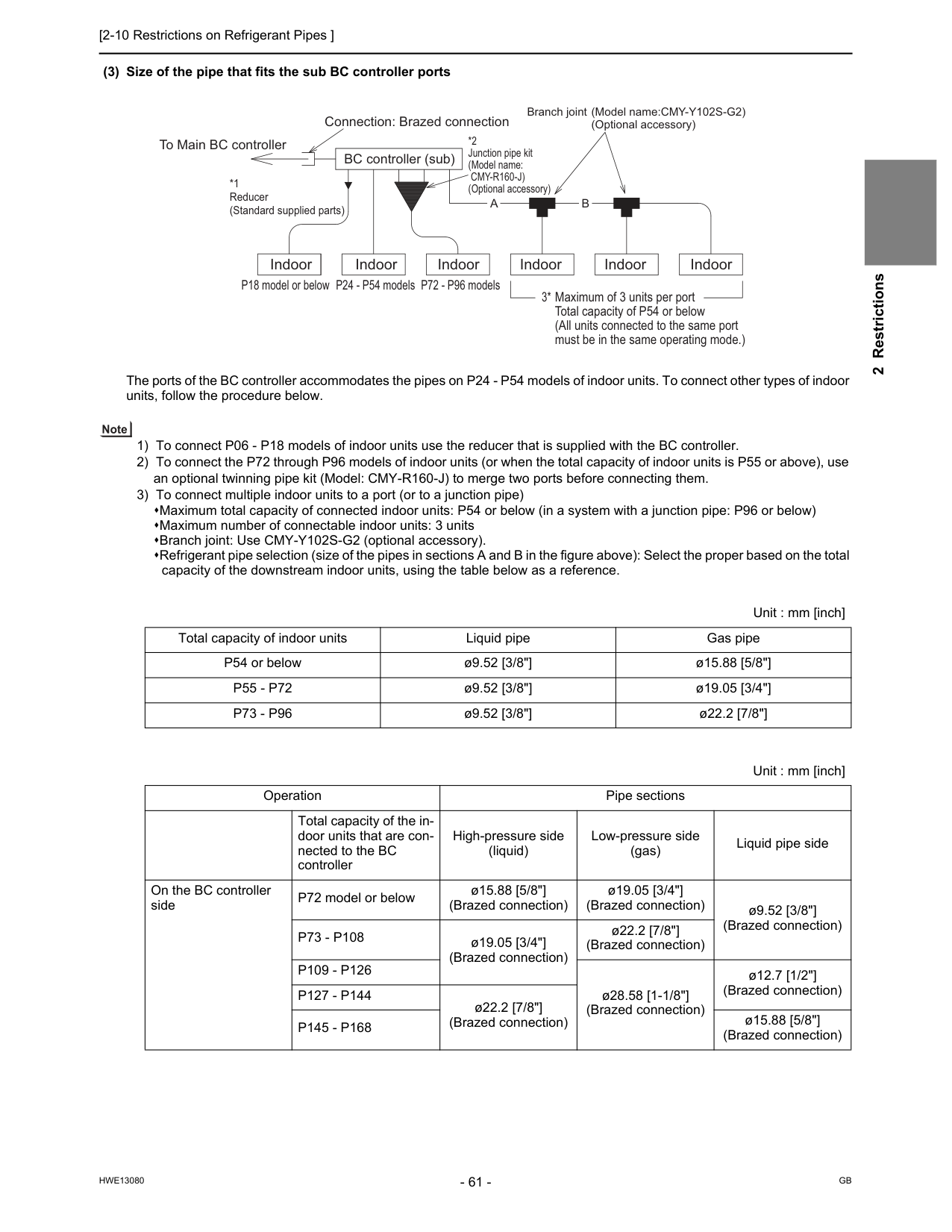
[2-10 Restrictions on Refrigerant Pipes ]
Hwe13080
Gb
2 Restrictions (3) Size of the pipe that fits the sub BC controller ports The ports of the BC controller accommodates the pipes on P24 - P54 models of indoor units. To connect other types of indoor units, follow the procedure below. 1) To connect P06 - P18 models of indoor units use the reducer that is supplied with the BC controller. 2) To connect the P72 through P96 models of indoor units (or when the total capacity of indoor units is P55 or above), use an optional twinning pipe kit (Model: CMY-R160-J) to merge two ports before connecting them. 3) To connect multiple indoor units to a port (or to a junction pipe) Maximum total capacity of connected indoor units: P54 or below (in a system with a junction pipe: P96 or below) Maximum number of connectable indoor units: 3 units Branch joint: Use CMY-Y102S-G2 (optional accessory). Refrigerant pipe selection (size of the pipes in sections A and B in the figure above): Select the proper based on the total capacity of the downstream indoor units, using the table below as a reference. Unit : mm [inch] Total capacity of indoor units Liquid pipe Gas pipe P54 or below ø9.52 [3/8"] ø15.88 [5/8"]P55 - P72
ø9.52 [3/8"] ø19.05 [3/4"]P73 - P96
ø9.52 [3/8"] ø22.2 [7/8"] Unit : mm [inch] Operation Pipe sections High-pressure side (liquid) Low-pressure side (gas) Liquid pipe side Total capacity of the in- door units that are con- nected to the BC controller On the BC controller side P72 model or below ø15.88 [5/8"] (Brazed connection) ø19.05 [3/4"] (Brazed connection) ø9.52 [3/8"] (Brazed connection)P73 - P108
ø19.05 [3/4"] (Brazed connection) ø22.2 [7/8"] (Brazed connection)P109 - P126
ø28.58 [1-1/8"] (Brazed connection) ø12.7 [1/2"] (Brazed connection)P127 - P144
ø22.2 [7/8"] (Brazed connection)P145 - P168
ø15.88 [5/8"] (Brazed connection)A
B
Indoor Indoor Indoor P18 model or below P24 - P54 models P72 - P96 models *2 Junction pipe kit (Model name:Cmy-R160-J)
(Optional accessory) BC controller (sub) To Main BC controller Connection: Brazed connection *1 Reducer (Standard supplied parts) Maximum of 3 units per port Total capacity of P54 or below (All units connected to the same port must be in the same operating mode.) 3* Indoor Indoor Indoor Branch joint (Model name:CMY-Y102S-G2)(Optional accessory)

[2-10 Restrictions on Refrigerant Pipes ]
Hwe13080
Gb
Hwe13080
Gb
Chapter 3 Major Components, Their Functions and Refrigerant Circuits 3-1 External Appearance and Refrigerant Circuit Components of Outdoor Unit................................ 65 3-1-1 External Appearance of Outdoor Unit................................................................................................... 65 3-1-2 Outdoor Unit Refrigerant Circuits.......................................................................................................... 66 3-2 Outdoor Unit Refrigerant Circuit Diagrams...................................................................................... 67 3-3 Functions of the Major Components of Outdoor Unit..................................................................... 69 3-4 Functions of the Major Components of Indoor Unit........................................................................ 72 3-5 External Appearance and Refrigerant Circuit Components of BC Controller .............................. 73 3-6 BC Controller Refrigerant Circuit Diagrams..................................................................................... 76 3-7 Functions of the Major Components of BC Controller.................................................................... 79
Hwe13080
Gb
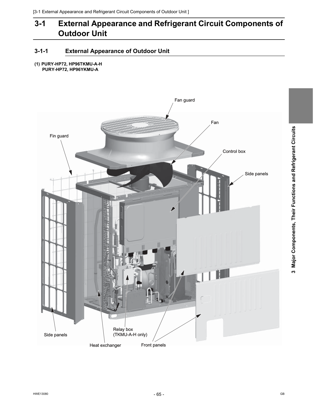
[3-1 External Appearance and Refrigerant Circuit Components of Outdoor Unit ]
Hwe13080
Gb
3 Major Components, Their Functions and Refrigerant Circuits 3 Major Components, Their Functions and Refrigerant Circuits 3-1 External Appearance and Refrigerant Circuit Components of Outdoor Unit 3-1-1 External Appearance of Outdoor Unit(1) Pury-Hp72, Hp96Tkmu-A-H
Pury-Hp72, Hp96Ykmu-A
Fan guard Fan guard Fan Fan Control box Control box Heat exchanger Heat exchanger Relay box (TKMU-A-H only) Relay box (TKMU-A-H only) Front panels Front panels Fin guard Fin guard Side panels Side panels Side panels Side panels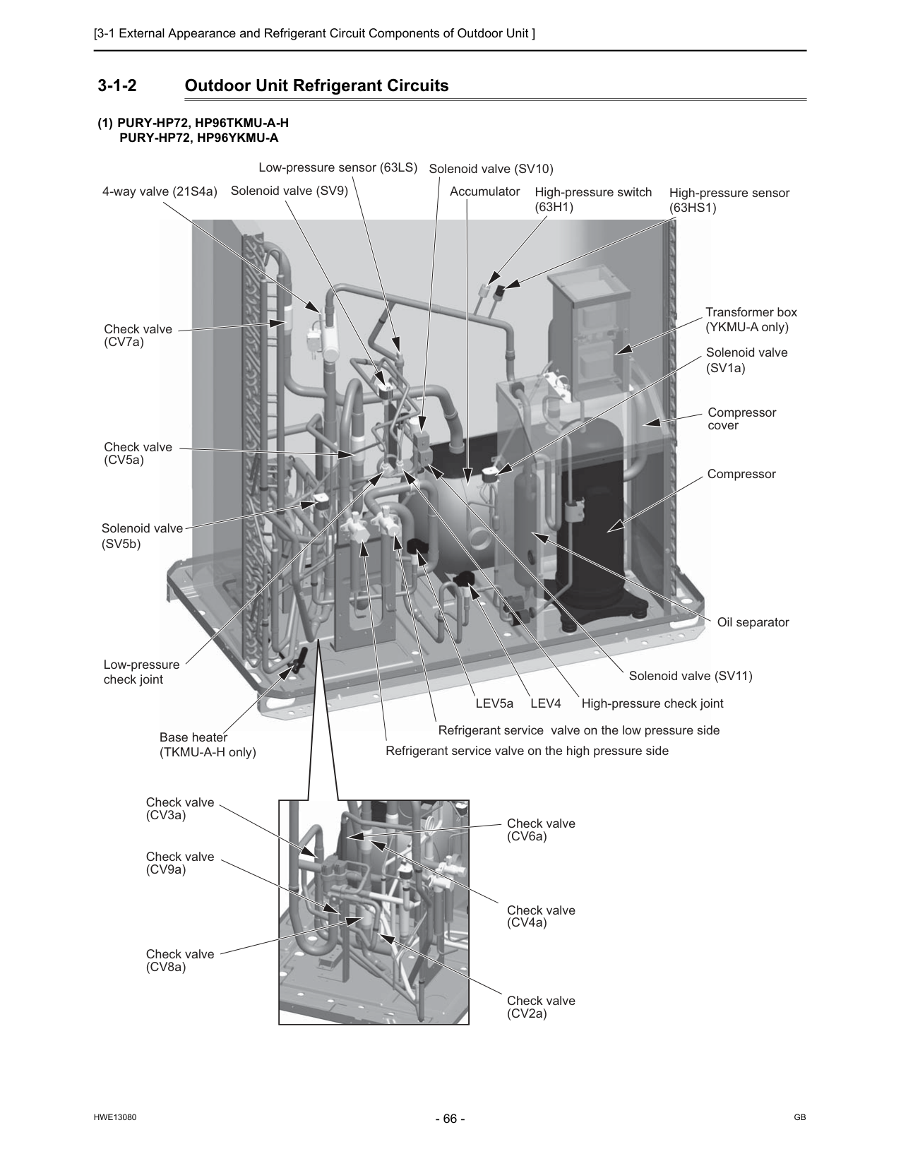
[3-1 External Appearance and Refrigerant Circuit Components of Outdoor Unit ]
Hwe13080
Gb
3-1-2 Outdoor Unit Refrigerant Circuits(1) Pury-Hp72, Hp96Tkmu-A-H
Pury-Hp72, Hp96Ykmu-A
Check valve (CV5a) Check valve (CV7a) Check valve (CV3a) Check valve (CV9a) Check valve (CV8a) Check valve (CV2a) Check valve (CV4a) Check valve (CV6a) 4-way valve (21S4a) Solenoid valve (SV9) Solenoid valve (SV10) Solenoid valve (SV11) Solenoid valve (SV5b) Solenoid valve (SV1a) Low-pressure sensor (63LS) High-pressure switch(63H1)
High-pressure sensor(63Hs1)
Transformer box (YKMU-A only) Accumulator Compressor cover Compressor Oil separator High-pressure check joint Low-pressure check joint Base heater (TKMU-A-H only)Lev4
LEV5a Refrigerant service valve on the low pressure side Refrigerant service valve on the high pressure side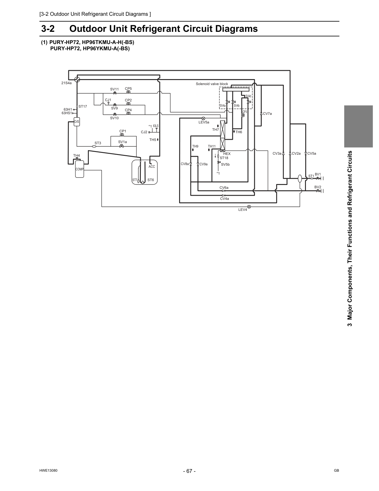
[3-2 Outdoor Unit Refrigerant Circuit Diagrams ]
Hwe13080
Gb
3 Major Components, Their Functions and Refrigerant Circuits 3-2 Outdoor Unit Refrigerant Circuit Diagrams(1) Pury-Hp72, Hp96Tkmu-A-H(-Bs)
Pury-Hp72, Hp96Ykmu-A(-Bs)
Solenoid valve blockTh4
Cj2
Bv2
Comp
21S4aSt1
63Ls
Bv1
CV8a CV6aTh7
SV4a SV4b SV4dAcc
St6
St7
St17
Th5
Th6
CV9aTh9
Th11
Sv9
Sv10
Sv11
CV4a CV2a CV7a CV3a CV5aCj1
SV5bHex
St18
63Hs1
63H1
St3
Cp1
SV1a LEV5aLev4
*1 *1Cp3
Cp2
Cp4
Cp5
O/S
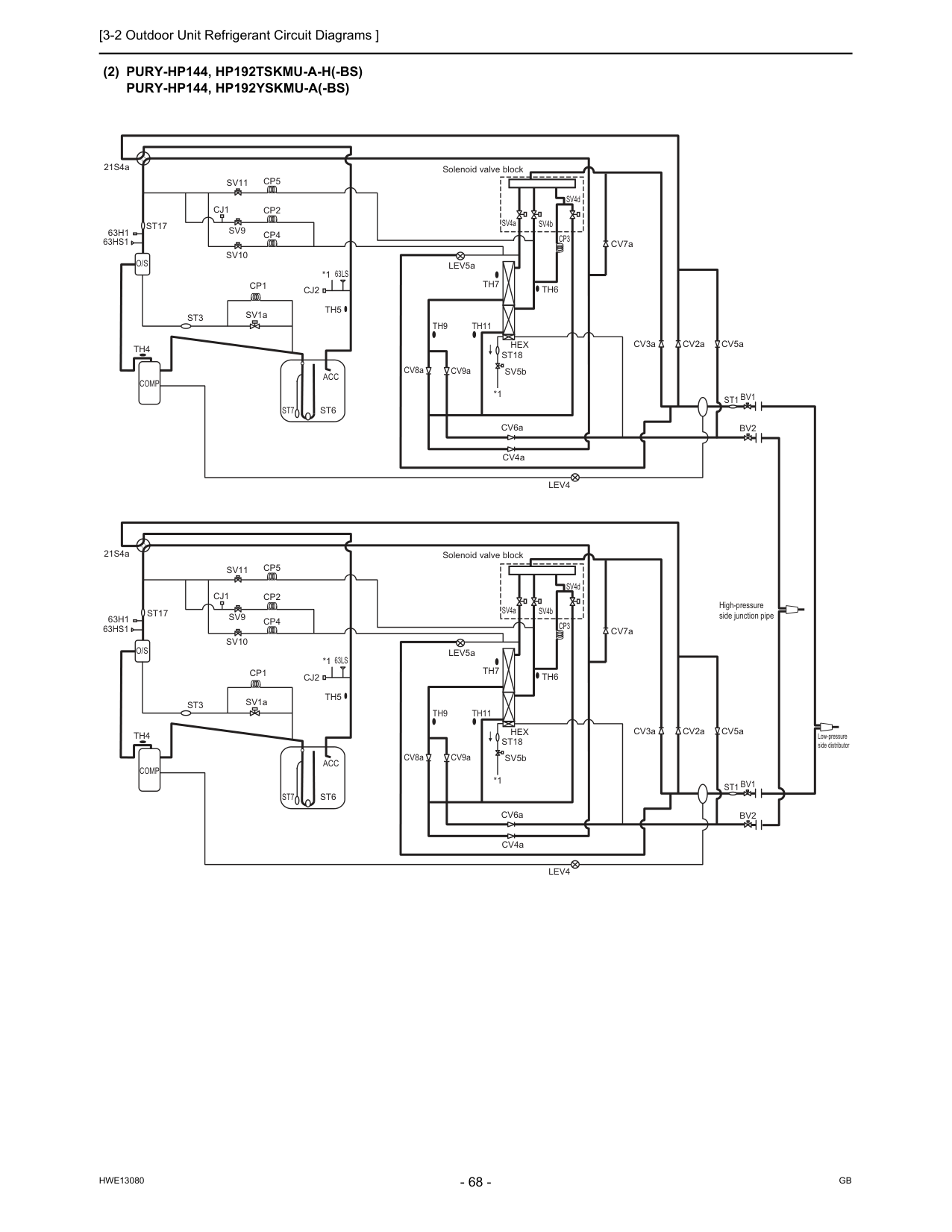
[3-2 Outdoor Unit Refrigerant Circuit Diagrams ]
Hwe13080
Gb
(2) Pury-Hp144, Hp192Tskmu-A-H(-Bs)
Pury-Hp144, Hp192Yskmu-A(-Bs)
*1 Low-pressure side distributor High-pressure side junction pipe Solenoid valve block Solenoid valve blockO/S
Th4
Cj2
Bv2
Comp
21S4aSt1
63Ls
Bv1
CV8a CV6aTh7
SV4a SV4b SV4dAcc
St6
St7
St17
Th5
Th6
CV9aTh9
Th11
Sv9
Sv10
Sv11
CV4a CV2a CV7a CV3a CV5aCj1
SV5bHex
St18
63Hs1
63H1
St3
Cp1
SV1a LEV5aLev4
*1Cp3
Cp2
Cp4
Cp5
O/S
Th4
Cj2
Bv2
Comp
21S4aSt1
63Ls
Bv1
CV8a CV6aTh7
SV4a SV4b SV4dAcc
St6
St7
St17
Th5
Th6
CV9aTh9
Th11
Sv9
Sv10
Sv11
CV4a CV2a CV7a CV3a CV5aCj1
SV5bHex
St18
63Hs1
63H1
St3
Cp1
SV1a LEV5aLev4
*1 *1Cp3
Cp2
Cp4
Cp5
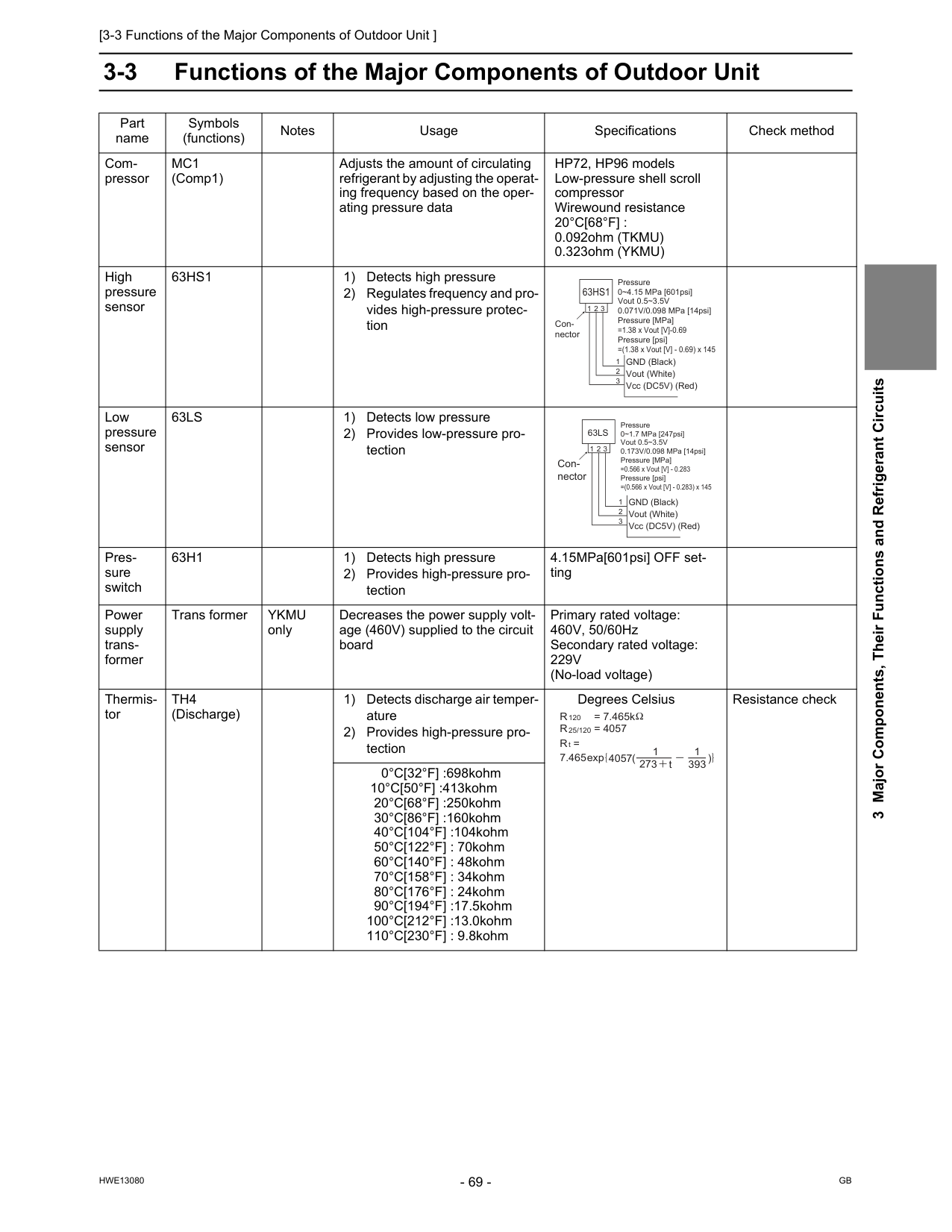
[3-3 Functions of the Major Components of Outdoor Unit ]
Hwe13080
Gb
3 Major Components, Their Functions and Refrigerant Circuits 3-3 Functions of the Major Components of Outdoor Unit Part name Symbols (functions) Notes Usage Specifications Check method Com- pressorMc1
(Comp1) Adjusts the amount of circulating refrigerant by adjusting the operat- ing frequency based on the oper- ating pressure data HP72, HP96 models Low-pressure shell scroll compressor Wirewound resistance20°C[68°F] :
0.092ohm (TKMU) 0.323ohm (YKMU) High pressure sensor63Hs1
1) Detects high pressure 2) Regulates frequency and pro- vides high-pressure protec- tion Low pressure sensor63Ls
1) Detects low pressure 2) Provides low-pressure pro- tection Pres- sure switch63H1
1) Detects high pressure 2) Provides high-pressure pro- tection 4.15MPa[601psi] OFF set- ting Power supply trans- former Trans formerYkmu
only Decreases the power supply volt- age (460V) supplied to the circuit board Primary rated voltage: 460V, 50/60Hz Secondary rated voltage:229V
(No-load voltage) Thermis- torTh4
(Discharge) 1) Detects discharge air temper- ature 2) Provides high-pressure pro- tection Degrees Celsius Resistance check 0°C[32°F] :698kohm 10°C[50°F] :413kohm 20°C[68°F] :250kohm 30°C[86°F] :160kohm 40°C[104°F] :104kohm 50°C[122°F] : 70kohm 60°C[140°F] : 48kohm 70°C[158°F] : 34kohm 80°C[176°F] : 24kohm 90°C[194°F] :17.5kohm 100°C[212°F] :13.0kohm 110°C[230°F] : 9.8kohm Pressure 0~4.15 MPa [601psi] Vout 0.5~3.5V 0.071V/0.098 MPa [14psi] Pressure [MPa] =1.38 x Vout [V]-0.69 Pressure [psi] =(1.38 x Vout [V] - 0.69) x 145 GND (Black) Vout (White) Vcc (DC5V) (Red) Con- nector63Hs1
1 1 2 3 2 3 Pressure 0~1.7 MPa [247psi] Vout 0.5~3.5V 0.173V/0.098 MPa [14psi] Pressure [MPa] =0.566 x Vout [V] - 0.283 Pressure [psi] =(0.566 x Vout [V] - 0.283) x 145 GND (Black) Vout (White) Vcc (DC5V) (Red) Con- nector63Ls
1 1 2 3 2 3 R = 7.465k 120R = 4057
R =
7.465 25/120 t 4057 273 t 1 393 1 exp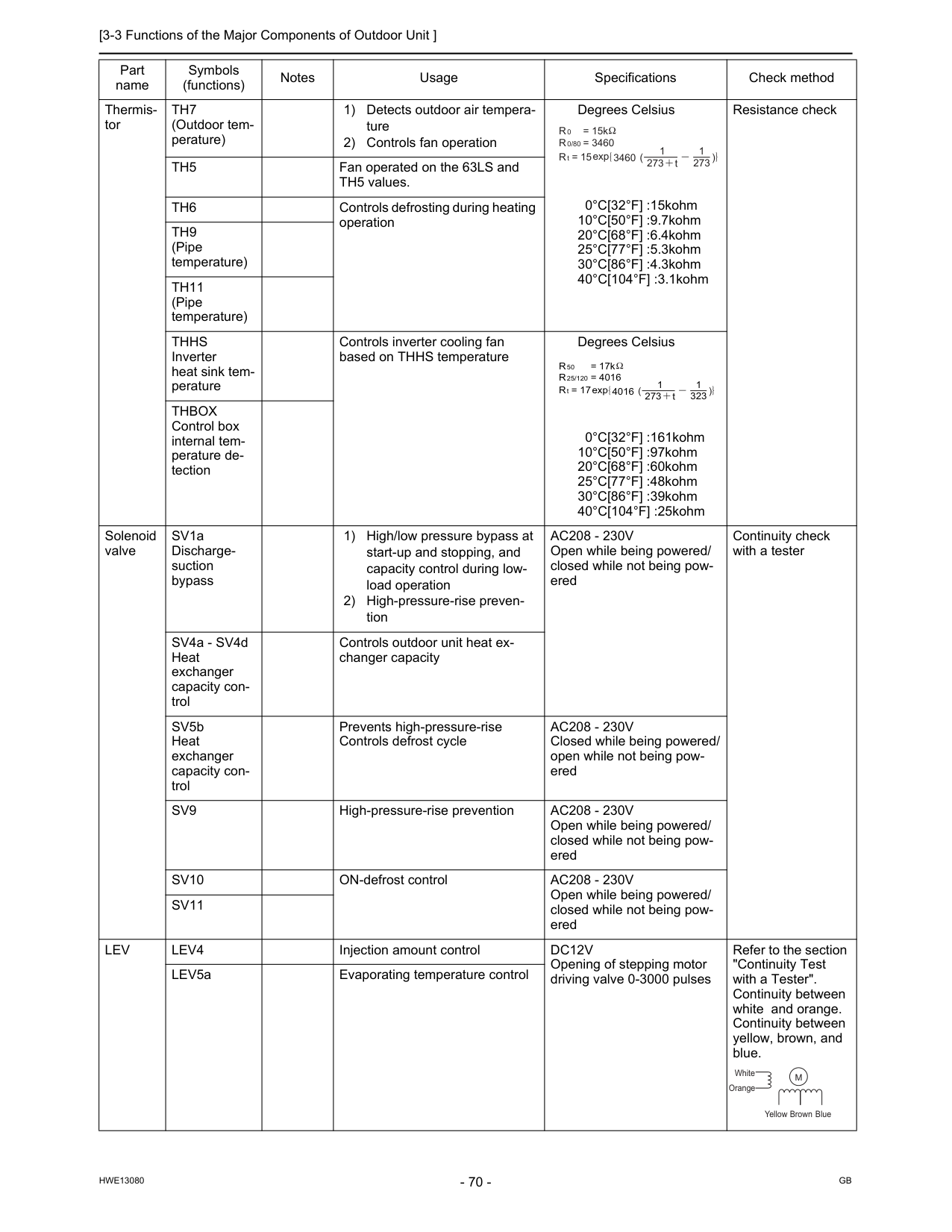
[3-3 Functions of the Major Components of Outdoor Unit ]
Hwe13080
Gb
Thermis- torTh7
(Outdoor tem- perature) 1) Detects outdoor air tempera- ture 2) Controls fan operation Degrees Celsius 0°C[32°F] :15kohm 10°C[50°F] :9.7kohm 20°C[68°F] :6.4kohm 25°C[77°F] :5.3kohm 30°C[86°F] :4.3kohm 40°C[104°F] :3.1kohm Resistance checkTh5
Fan operated on the 63LS and TH5 values.Th6
Controls defrosting during heating operationTh9
(Pipe temperature)Th11
(Pipe temperature)Thhs
Inverter heat sink tem- perature Controls inverter cooling fan based on THHS temperature Degrees Celsius 0°C[32°F] :161kohm 10°C[50°F] :97kohm 20°C[68°F] :60kohm 25°C[77°F] :48kohm 30°C[86°F] :39kohm 40°C[104°F] :25kohmThbox
Control box internal tem- perature de- tection Solenoid valve SV1a Discharge- suction bypass 1) High/low pressure bypass at start-up and stopping, and capacity control during low- load operation 2) High-pressure-rise preven- tionAc208 - 230V
Open while being powered/ closed while not being pow- ered Continuity check with a tester SV4a - SV4d Heat exchanger capacity con- trol Controls outdoor unit heat ex- changer capacity SV5b Heat exchanger capacity con- trol Prevents high-pressure-rise Controls defrost cycleAc208 - 230V
Closed while being powered/ open while not being pow- eredSv9
High-pressure-rise preventionAc208 - 230V
Open while being powered/ closed while not being pow- eredSv10
ON-defrost controlAc208 - 230V
Open while being powered/ closed while not being pow- eredSv11
Lev
Lev4
Injection amount controlDc12V
Opening of stepping motor driving valve 0-3000 pulses Refer to the section "Continuity Test with a Tester". Continuity between white and orange. Continuity between yellow, brown, and blue. LEV5a Evaporating temperature control Part name Symbols (functions) Notes Usage Specifications Check method R = 15k 0R = 3460
R = 15
0/80 t 3460 273 t 1 273 1 exp R = 17k 50R = 4016
R = 17
25/120 t 4016 273 t 1 323 1 exp Yellow White Orange Brown BlueM
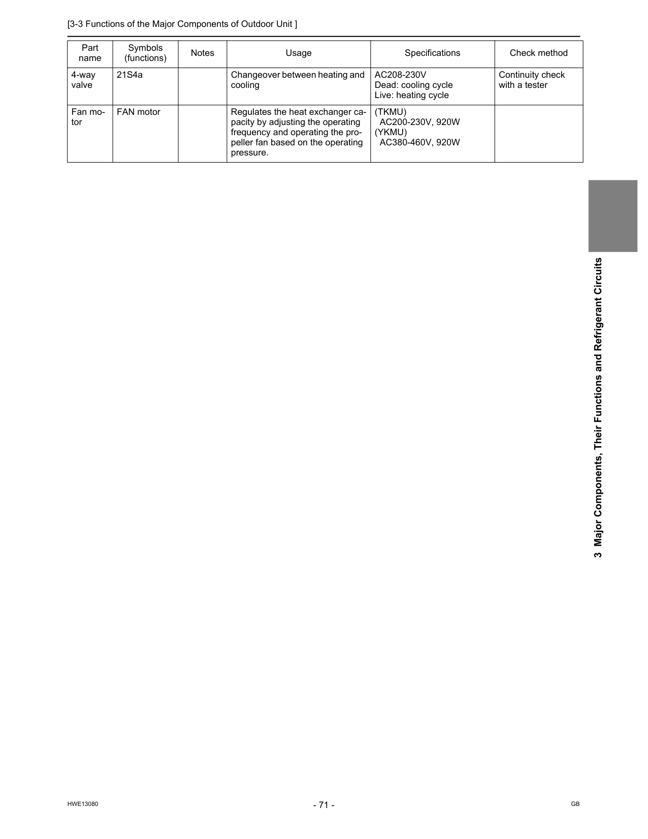
[3-3 Functions of the Major Components of Outdoor Unit ]
Hwe13080
Gb
3 Major Components, Their Functions and Refrigerant Circuits 4-way valve 21S4a Changeover between heating and coolingAc208-230V
Dead: cooling cycle Live: heating cycle Continuity check with a tester Fan mo- tor FAN motor Regulates the heat exchanger ca- pacity by adjusting the operating frequency and operating the pro- peller fan based on the operating pressure.(Tkmu)
Ac200-230V, 920W
(Ykmu)
Ac380-460V, 920W
Part name Symbols (functions) Notes Usage Specifications Check method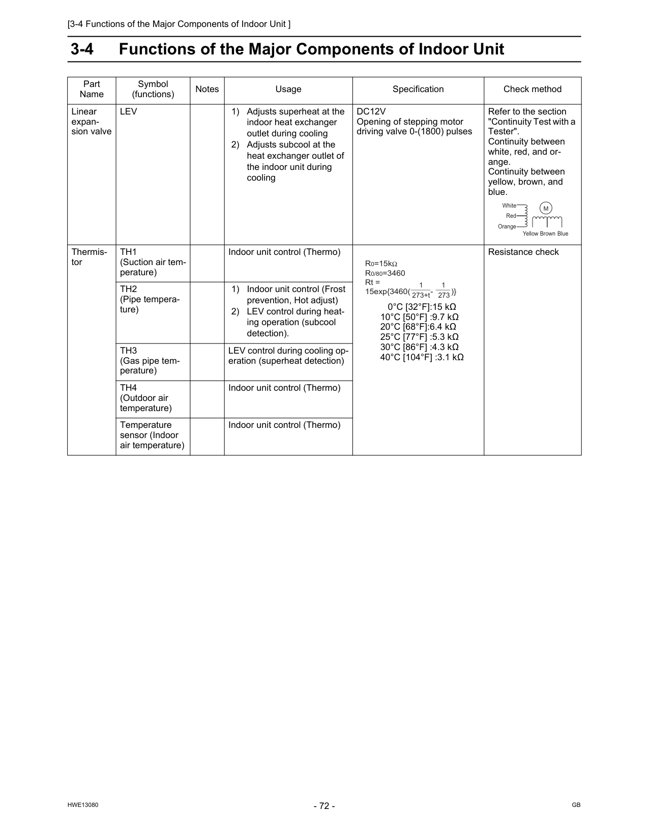
[3-4 Functions of the Major Components of Indoor Unit ]
Hwe13080
Gb
3-4 Functions of the Major Components of Indoor Unit Part Name Symbol (functions) Notes Usage Specification Check method Linear expan- sion valveLev
1) Adjusts superheat at the indoor heat exchanger outlet during cooling 2) Adjusts subcool at the heat exchanger outlet of the indoor unit during coolingDc12V
Opening of stepping motor driving valve 0-(1800) pulses Refer to the section "Continuity Test with a Tester". Continuity between white, red, and or- ange. Continuity between yellow, brown, and blue. Thermis- torTh1
(Suction air tem- perature) Indoor unit control (Thermo) 0°C [32°F]:15 kΩ 10°C [50°F] :9.7 kΩ 20°C [68°F]:6.4 kΩ 25°C [77°F] :5.3 kΩ 30°C [86°F] :4.3 kΩ 40°C [104°F] :3.1 kΩ Resistance checkTh2
(Pipe tempera- ture) 1) Indoor unit control (Frost prevention, Hot adjust) 2) LEV control during heat- ing operation (subcool detection).Th3
(Gas pipe tem- perature) LEV control during cooling op- eration (superheat detection)Th4
(Outdoor air temperature) Indoor unit control (Thermo) Temperature sensor (Indoor air temperature) Indoor unit control (Thermo) Yellow White Red Orange Brown BlueM
1 273+t R0=15kR0/80=3460
Rt = 15exp{3460( - )} 1 273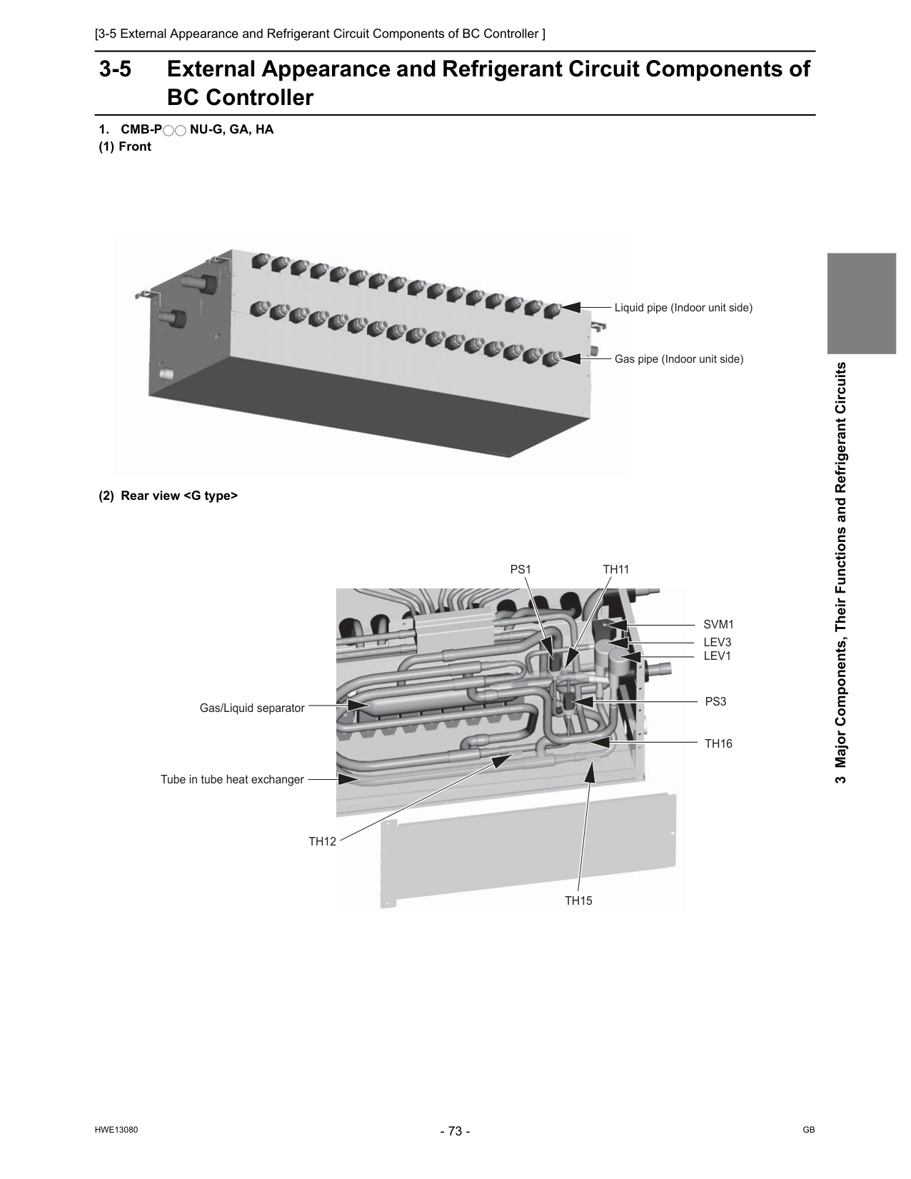
[3-5 External Appearance and Refrigerant Circuit Components of BC Controller ]
Hwe13080
Gb
3 Major Components, Their Functions and Refrigerant Circuits 3-5 External Appearance and Refrigerant Circuit Components of BC Controller1. Cmb-P
Nu-G, Ga, Ha
(1) Front (2) Rear viewTh12
Th15
Th16
Th11
Svm1
Lev1
Lev3
Ps1
Ps3
Tube in tube heat exchanger Gas/Liquid separator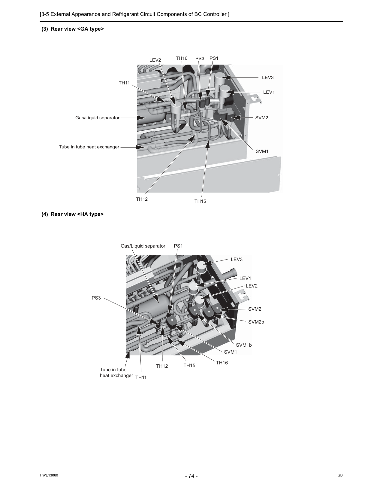
[3-5 External Appearance and Refrigerant Circuit Components of BC Controller ]
Hwe13080
Gb
(3) Rear viewTh12
Th15
Th16
Th11
Svm2
Svm1
Lev1
Lev3
Lev2
Ps1
Ps3
Tube in tube heat exchanger Gas/Liquid separator Gas/Liquid separatorLev3
Lev1
Lev2
Svm2
SVM2b SVM1bSvm1
Th16
Th15
Th12
Th11
Ps1
Ps3
Tube in tube heat exchanger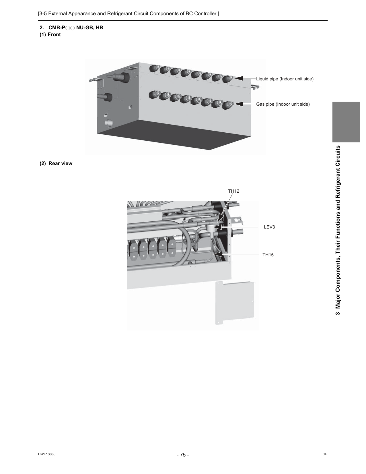
[3-5 External Appearance and Refrigerant Circuit Components of BC Controller ]
Hwe13080
Gb
3 Major Components, Their Functions and Refrigerant Circuits2. Cmb-P
Nu-Gb, Hb
(1) Front (2) Rear view Liquid pipe (Indoor unit side) Gas pipe (Indoor unit side)Th15
Th12
Lev3
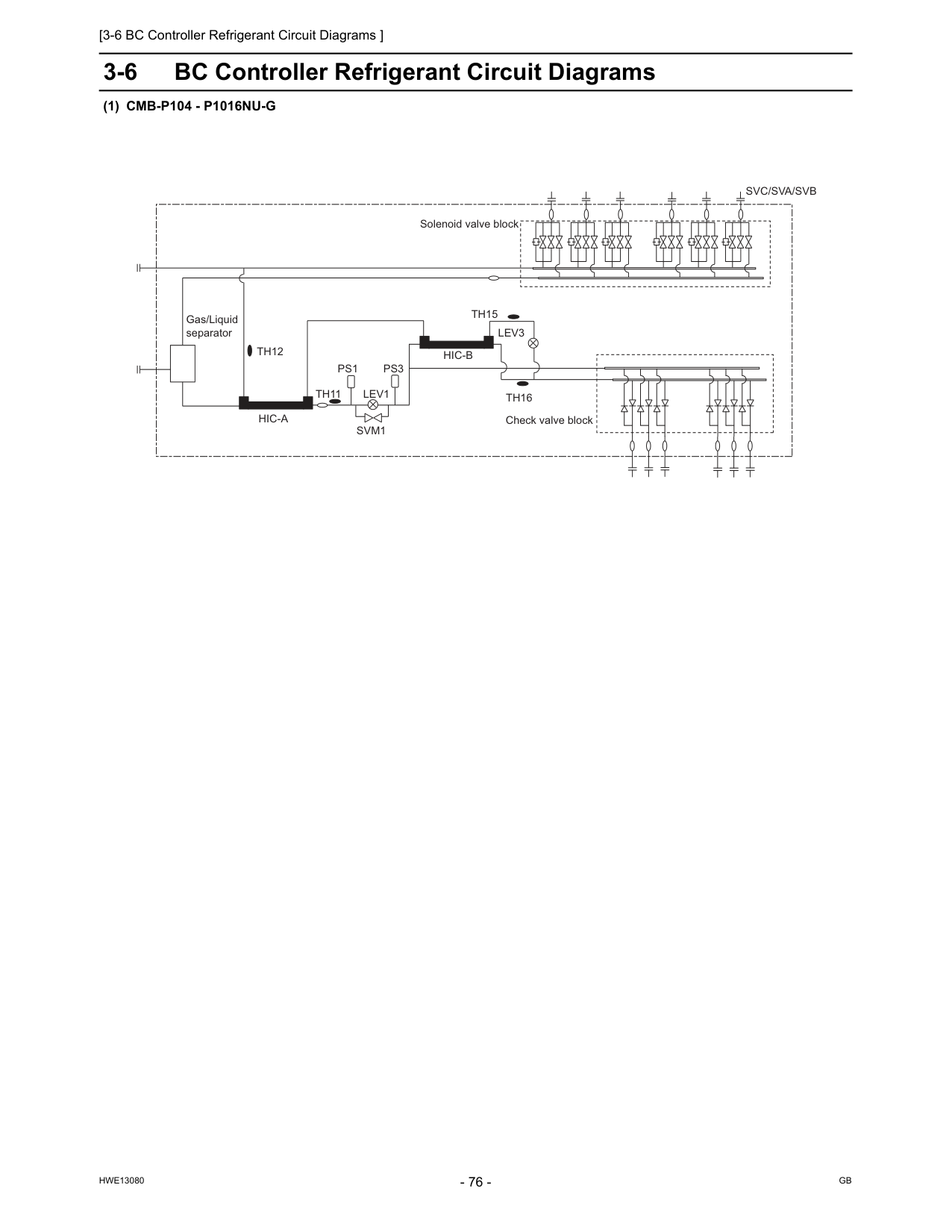
[3-6 BC Controller Refrigerant Circuit Diagrams ]
Hwe13080
Gb
3-6 BC Controller Refrigerant Circuit Diagrams(1) Cmb-P104 - P1016Nu-G
Th15
Th12
Hic-B
Hic-A
Lev3
Lev1
Th16
Ps3
Ps1
Th11
Svm1
Gas/Liquid separator Check valve block Solenoid valve blockSvc/Sva/Svb
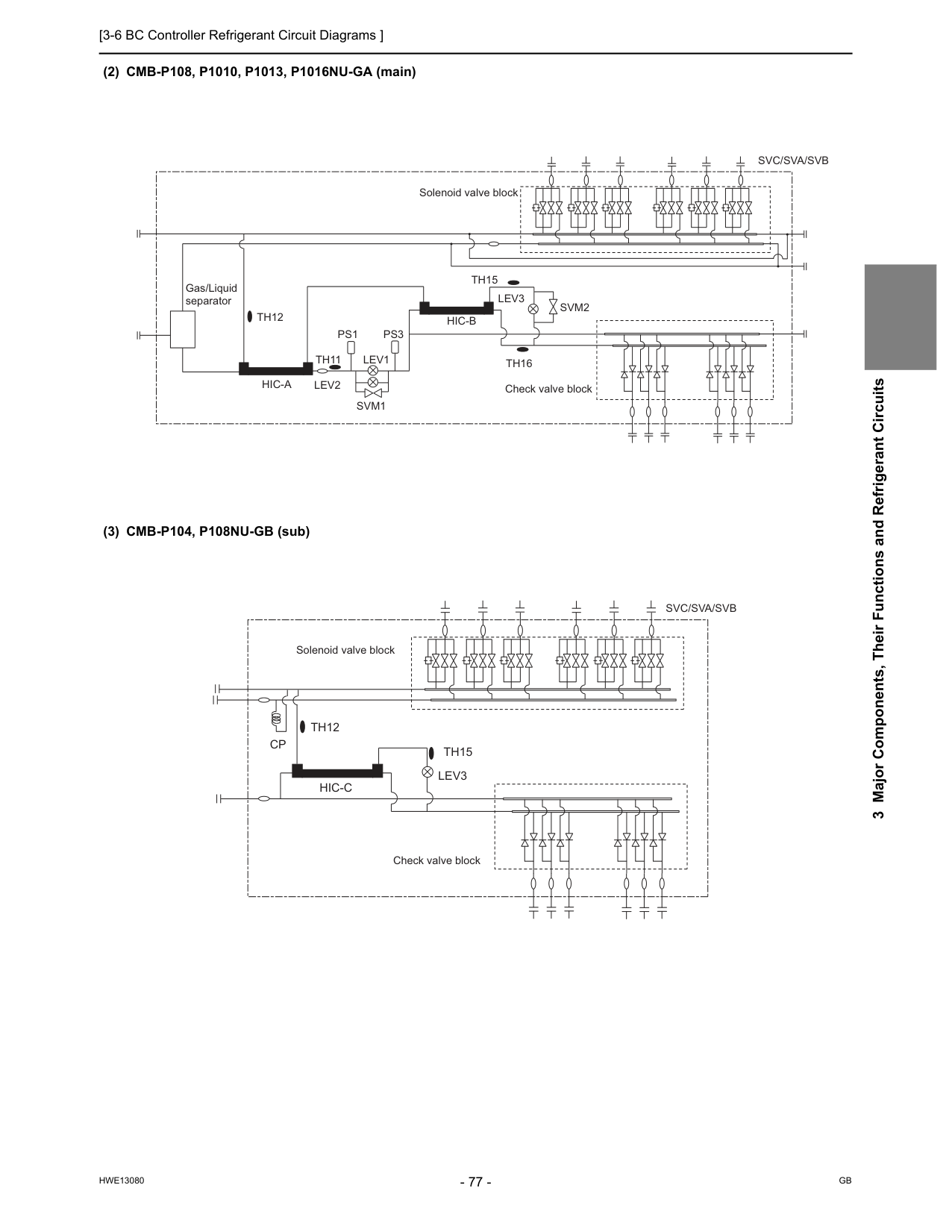
[3-6 BC Controller Refrigerant Circuit Diagrams ]
Hwe13080
Gb
3 Major Components, Their Functions and Refrigerant Circuits (2) CMB-P108, P1010, P1013, P1016NU-GA (main) (3) CMB-P104, P108NU-GB (sub)Th15
Th12
Lev3
Svm2
Lev1
Lev2
Th16
Ps3
Ps1
Th11
Svm1
Hic-B
Hic-A
Gas/Liquid separator Check valve block Solenoid valve blockSvc/Sva/Svb
Th15
Th12
Hic-C
Cp
Lev3
Check valve block Solenoid valve blockSvc/Sva/Svb
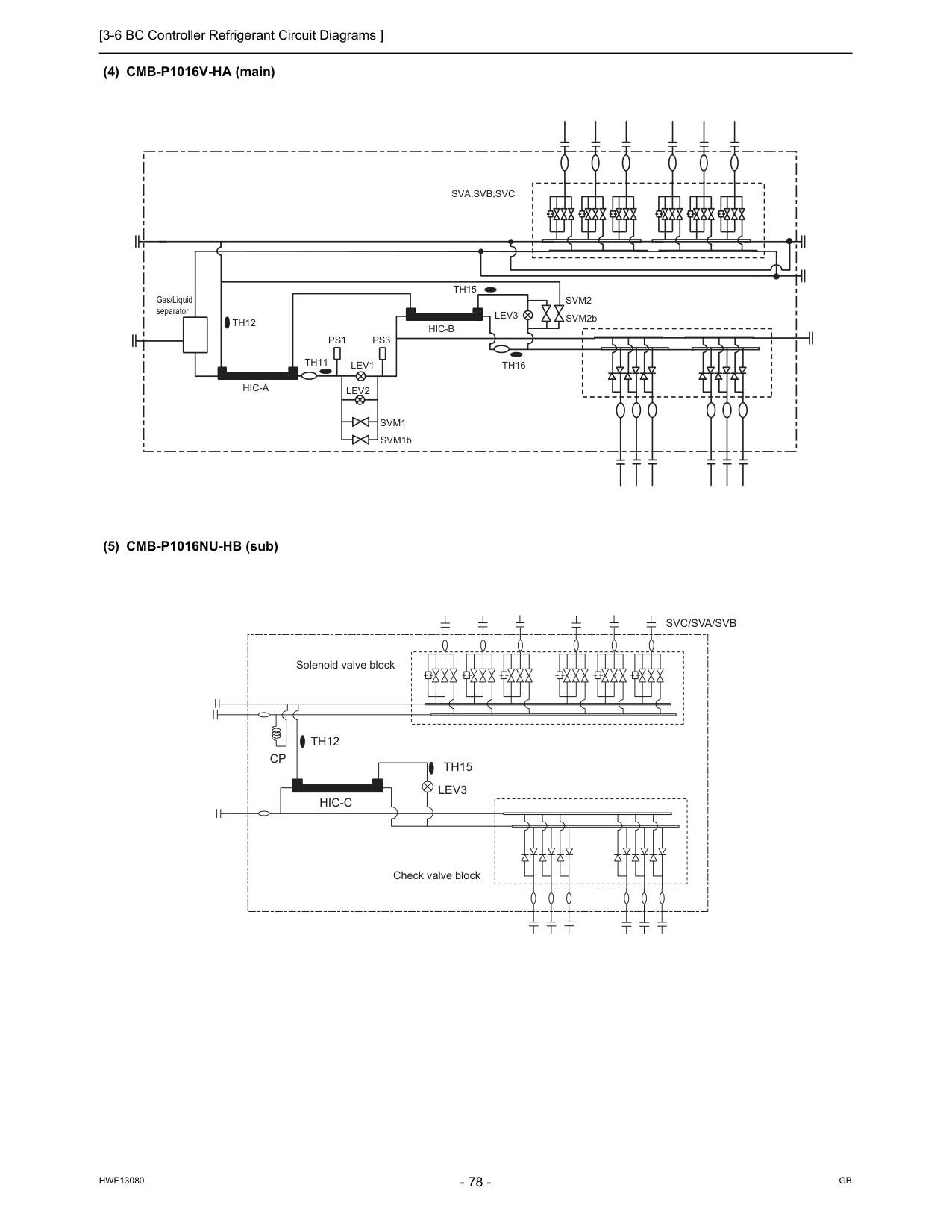
[3-6 BC Controller Refrigerant Circuit Diagrams ]
Hwe13080
Gb
(4) CMB-P1016V-HA (main) (5) CMB-P1016NU-HB (sub)Th15
Th12
Gas/Liquid separatorLev3
Lev1
Th16
Ps1
Ps3
Th11
Sva,Svb,Svc
Svm1
Svm2
Hic-A
Hic-B
Lev2
SVM1b SVM2bTh15
Th12
Hic-C
Cp
Lev3
Check valve block Solenoid valve blockSvc/Sva/Svb
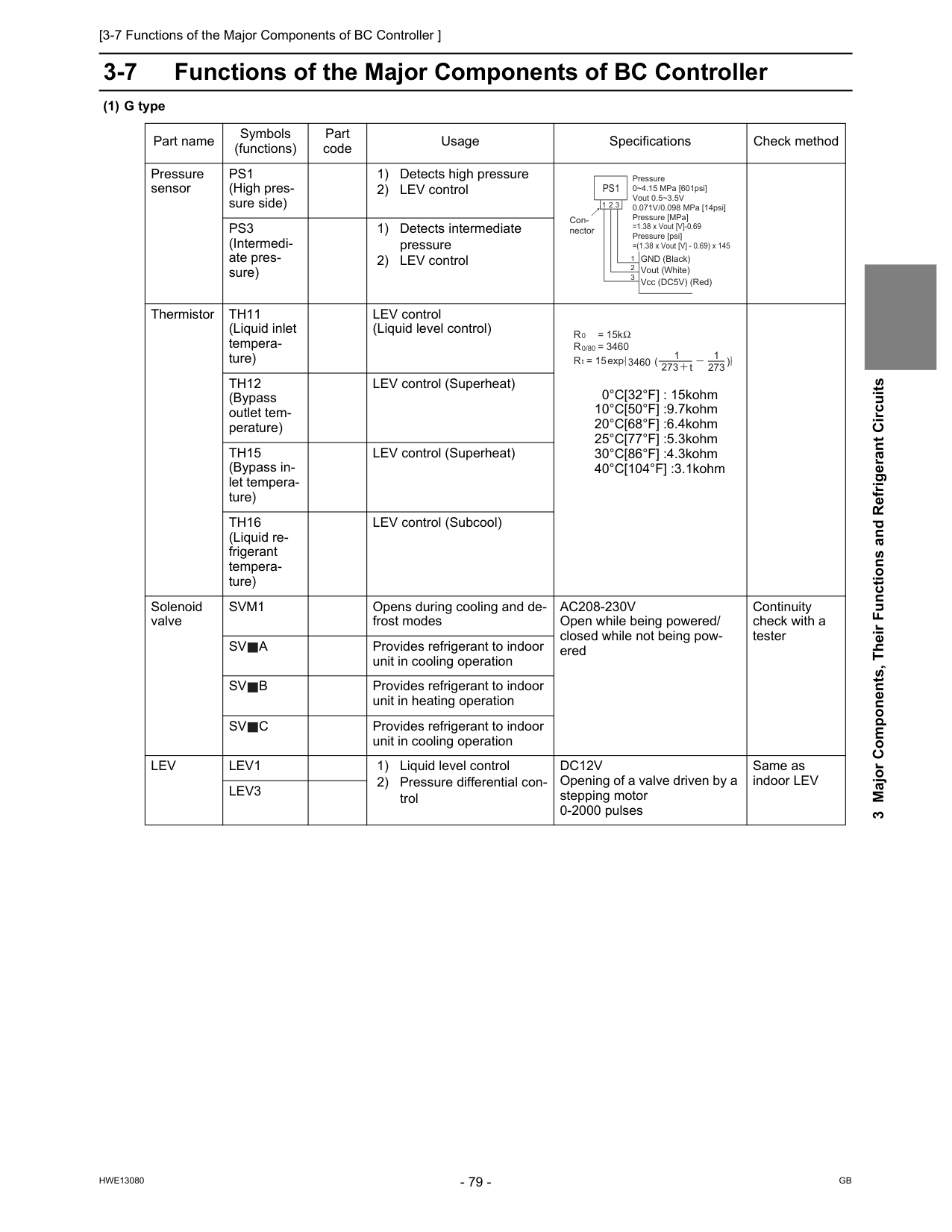
[3-7 Functions of the Major Components of BC Controller ]
Hwe13080
Gb
3 Major Components, Their Functions and Refrigerant Circuits 3-7 Functions of the Major Components of BC Controller (1) G type Part name Symbols (functions) Part code Usage Specifications Check method Pressure sensorPs1
(High pres- sure side) 1) Detects high pressure 2) LEV controlPs3
(Intermedi- ate pres- sure) 1) Detects intermediate pressure 2) LEV control ThermistorTh11
(Liquid inlet tempera- ture) LEV control (Liquid level control) 0°C[32°F] : 15kohm 10°C[50°F] :9.7kohm 20°C[68°F] :6.4kohm 25°C[77°F] :5.3kohm 30°C[86°F] :4.3kohm 40°C[104°F] :3.1kohmTh12
(Bypass outlet tem- perature) LEV control (Superheat)Th15
(Bypass in- let tempera- ture) LEV control (Superheat)Th16
(Liquid re- frigerant tempera- ture) LEV control (Subcool) Solenoid valveSvm1
Opens during cooling and de- frost modesAc208-230V
Open while being powered/ closed while not being pow- ered Continuity check with a testerSv
A
Provides refrigerant to indoor unit in cooling operationSv
B
Provides refrigerant to indoor unit in heating operationSv
C
Provides refrigerant to indoor unit in cooling operationLev
Lev1
1) Liquid level control 2) Pressure differential con- trolDc12V
Opening of a valve driven by a stepping motor 0-2000 pulses Same as indoor LEVLev3
Pressure 0~4.15 MPa [601psi] Vout 0.5~3.5V 0.071V/0.098 MPa [14psi] Pressure [MPa] =1.38 x Vout [V]-0.69 Pressure [psi] =(1.38 x Vout [V] - 0.69) x 145 GND (Black) Vout (White) Vcc (DC5V) (Red) Con- nectorPs1
1 1 2 3 2 3 R = 15k 0R = 3460
R = 15
0/80 t 3460 273 t 1 273 1 exp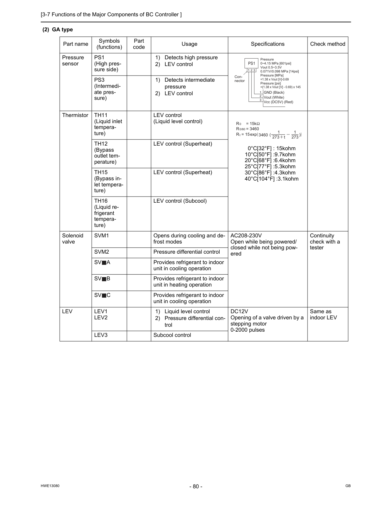
[3-7 Functions of the Major Components of BC Controller ]
Hwe13080
Gb
(2) GA type Part name Symbols (functions) Part code Usage Specifications Check method Pressure sensorPs1
(High pres- sure side) 1) Detects high pressure 2) LEV controlPs3
(Intermedi- ate pres- sure) 1) Detects intermediate pressure 2) LEV control ThermistorTh11
(Liquid inlet tempera- ture) LEV control (Liquid level control) 0°C[32°F] : 15kohm 10°C[50°F] :9.7kohm 20°C[68°F] :6.4kohm 25°C[77°F] :5.3kohm 30°C[86°F] :4.3kohm 40°C[104°F] :3.1kohmTh12
(Bypass outlet tem- perature) LEV control (Superheat)Th15
(Bypass in- let tempera- ture) LEV control (Superheat)Th16
(Liquid re- frigerant tempera- ture) LEV control (Subcool) Solenoid valveSvm1
Opens during cooling and de- frost modesAc208-230V
Open while being powered/ closed while not being pow- ered Continuity check with a testerSvm2
Pressure differential controlSv
A
Provides refrigerant to indoor unit in cooling operationSv
B
Provides refrigerant to indoor unit in heating operationSv
C
Provides refrigerant to indoor unit in cooling operationLev
Lev1
Lev2
1) Liquid level control 2) Pressure differential con- trolDc12V
Opening of a valve driven by a stepping motor 0-2000 pulses Same as indoor LEVLev3
Subcool control Pressure 0~4.15 MPa [601psi] Vout 0.5~3.5V 0.071V/0.098 MPa [14psi] Pressure [MPa] =1.38 x Vout [V]-0.69 Pressure [psi] =(1.38 x Vout [V] - 0.69) x 145 GND (Black) Vout (White) Vcc (DC5V) (Red) Con- nectorPs1
1 1 2 3 2 3 R = 15k 0R = 3460
R = 15
0/80 t 3460 273 t 1 273 1 exp
[3-7 Functions of the Major Components of BC Controller ]
Hwe13080
Gb
3 Major Components, Their Functions and Refrigerant Circuits (3) GB type Part name Symbols (functions) Part code Usage Specifications Check method ThermistorTh12
(Bypass outlet tem- perature) LEV control (Superheat) 0°C[32°F] : 15kohm 10°C[50°F] :9.7kohm 20°C[68°F] :6.4kohm 25°C[77°F] :5.3kohm 30°C[86°F] :4.3kohm 40°C[104°F] :3.1kohmTh15
(Bypass in- let tempera- ture) LEV control (Superheat) Solenoid valveSv
A
Provides refrigerant to indoor unit in cooling operationAc208-230V
Open while being powered/ closed while not being pow- ered Continuity check with a testerSv
B
Provides refrigerant to indoor unit in heating operationSv
C
Provides refrigerant to indoor unit in cooling operationLev
Lev3
Pressure differential controlDc12V
Opening of a valve driven by a stepping motor 0-2000 pulses Same as indoor LEV R = 15k 0R = 3460
R = 15
0/80 t 3460 273 t 1 273 1 exp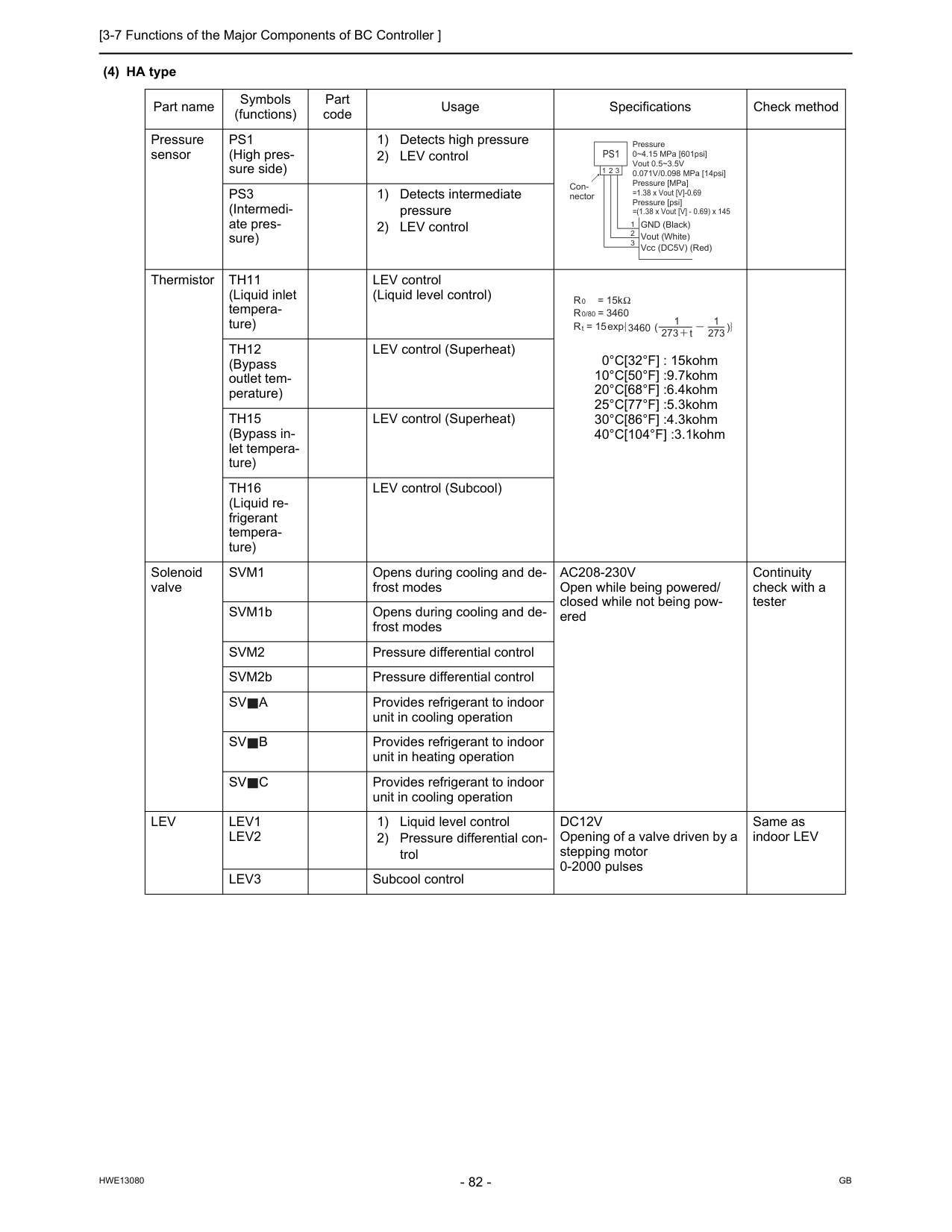
[3-7 Functions of the Major Components of BC Controller ]
Hwe13080
Gb
(4) HA type Part name Symbols (functions) Part code Usage Specifications Check method Pressure sensorPs1
(High pres- sure side) 1) Detects high pressure 2) LEV controlPs3
(Intermedi- ate pres- sure) 1) Detects intermediate pressure 2) LEV control ThermistorTh11
(Liquid inlet tempera- ture) LEV control (Liquid level control) 0°C[32°F] : 15kohm 10°C[50°F] :9.7kohm 20°C[68°F] :6.4kohm 25°C[77°F] :5.3kohm 30°C[86°F] :4.3kohm 40°C[104°F] :3.1kohmTh12
(Bypass outlet tem- perature) LEV control (Superheat)Th15
(Bypass in- let tempera- ture) LEV control (Superheat)Th16
(Liquid re- frigerant tempera- ture) LEV control (Subcool) Solenoid valveSvm1
Opens during cooling and de- frost modesAc208-230V
Open while being powered/ closed while not being pow- ered Continuity check with a tester SVM1b Opens during cooling and de- frost modesSvm2
Pressure differential control SVM2b Pressure differential controlSv
A
Provides refrigerant to indoor unit in cooling operationSv
B
Provides refrigerant to indoor unit in heating operationSv
C
Provides refrigerant to indoor unit in cooling operationLev
Lev1
Lev2
1) Liquid level control 2) Pressure differential con- trolDc12V
Opening of a valve driven by a stepping motor 0-2000 pulses Same as indoor LEVLev3
Subcool control Pressure 0~4.15 MPa [601psi] Vout 0.5~3.5V 0.071V/0.098 MPa [14psi] Pressure [MPa] =1.38 x Vout [V]-0.69 Pressure [psi] =(1.38 x Vout [V] - 0.69) x 145 GND (Black) Vout (White) Vcc (DC5V) (Red) Con- nectorPs1
1 1 2 3 2 3 R = 15k 0R = 3460
R = 15
0/80 t 3460 273 t 1 273 1 exp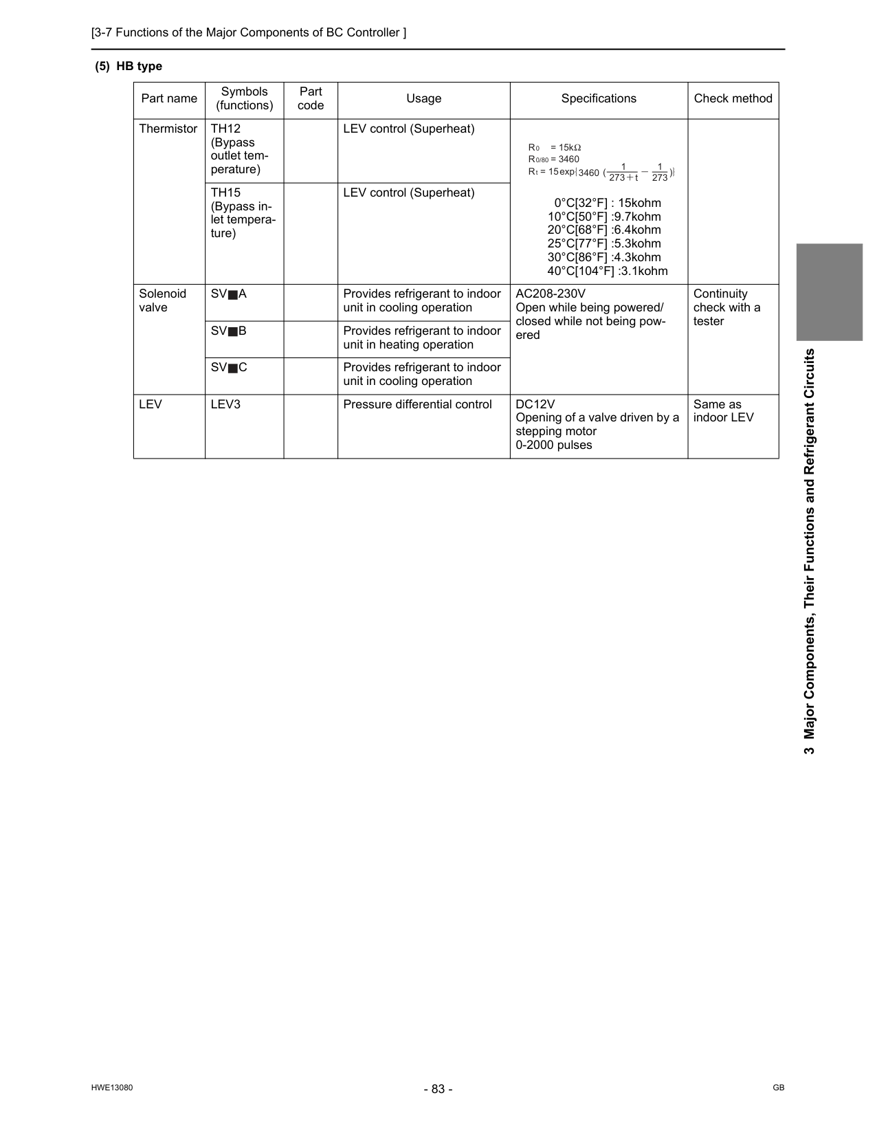
[3-7 Functions of the Major Components of BC Controller ]
Hwe13080
Gb
3 Major Components, Their Functions and Refrigerant Circuits (5) HB type Part name Symbols (functions) Part code Usage Specifications Check method ThermistorTh12
(Bypass outlet tem- perature) LEV control (Superheat) 0°C[32°F] : 15kohm 10°C[50°F] :9.7kohm 20°C[68°F] :6.4kohm 25°C[77°F] :5.3kohm 30°C[86°F] :4.3kohm 40°C[104°F] :3.1kohmTh15
(Bypass in- let tempera- ture) LEV control (Superheat) Solenoid valveSv
A
Provides refrigerant to indoor unit in cooling operationAc208-230V
Open while being powered/ closed while not being pow- ered Continuity check with a testerSv
B
Provides refrigerant to indoor unit in heating operationSv
C
Provides refrigerant to indoor unit in cooling operationLev
Lev3
Pressure differential controlDc12V
Opening of a valve driven by a stepping motor 0-2000 pulses Same as indoor LEV R = 15k 0R = 3460
R = 15
0/80 t 3460 273 t 1 273 1 exp
[3-7 Functions of the Major Components of BC Controller ]
Hwe13080
Gb
Hwe13080
Gb
Chapter 4 Electrical Components and Wiring Diagrams 4-1 Outdoor Unit Circuit Board Arrangement......................................................................................... 87 4-1-1 Outdoor Unit Control Box...................................................................................................................... 87 4-1-2 Transformer Box ................................................................................................................................... 89 4-2 Outdoor Unit Circuit Board Components ......................................................................................... 90 4-2-1 Control Board........................................................................................................................................ 90 4-2-2 M-NET Board (Transmission Power Supply Board) ............................................................................. 91 4-2-3 INV Board ............................................................................................................................................. 92 4-2-4 Fan Board ............................................................................................................................................. 94 4-2-5 Noise Filter............................................................................................................................................ 96 4-3 Outdoor Unit Electrical Wiring Diagrams ......................................................................................... 98 4-4 Transmission Booster Electrical Wiring Diagrams ....................................................................... 100 4-5 BC Controller Circuit Board Arrangement ..................................................................................... 101 4-5-1 BC Controller Control Box................................................................................................................... 101 4-6 BC Controller Circuit Board Components...................................................................................... 102 4-6-1 BC Board ............................................................................................................................................ 102 4-6-2 Four-Relay Board................................................................................................................................ 103 4-6-3 Ten-Relay Board................................................................................................................................. 103 4-7 BC Controller Electrical Wiring Diagrams...................................................................................... 104
Hwe13080
Gb
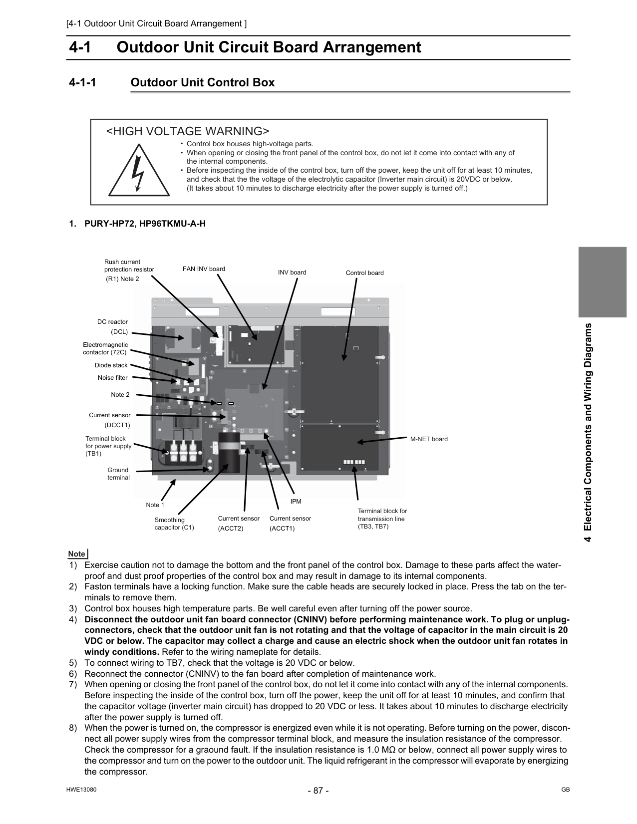
[4-1 Outdoor Unit Circuit Board Arrangement ]
Hwe13080
Gb
4 Electrical Components and Wiring Diagrams 4 Electrical Components and Wiring Diagrams 4-1 Outdoor Unit Circuit Board Arrangement 4-1-1 Outdoor Unit Control Box1. Pury-Hp72, Hp96Tkmu-A-H
1) Exercise caution not to damage the bottom and the front panel of the control box. Damage to these parts affect the water- proof and dust proof properties of the control box and may result in damage to its internal components. 2) Faston terminals have a locking function. Make sure the cable heads are securely locked in place. Press the tab on the ter- minals to remove them. 3) Control box houses high temperature parts. Be well careful even after turning off the power source. 4) Disconnect the outdoor unit fan board connector (CNINV) before performing maintenance work. To plug or unplug- connectors, check that the outdoor unit fan is not rotating and that the voltage of capacitor in the main circuit is 20 VDC or below. The capacitor may collect a charge and cause an electric shock when the outdoor unit fan rotates in windy conditions. Refer to the wiring nameplate for details. 5) To connect wiring to TB7, check that the voltage is 20 VDC or below. 6) Reconnect the connector (CNINV) to the fan board after completion of maintenance work. 7) When opening or closing the front panel of the control box, do not let it come into contact with any of the internal components. Before inspecting the inside of the control box, turn off the power, keep the unit off for at least 10 minutes, and confirm that the capacitor voltage (inverter main circuit) has dropped to 20 VDC or less. It takes about 10 minutes to discharge electricity after the power supply is turned off. 8) When the power is turned on, the compressor is energized even while it is not operating. Before turning on the power, discon- nect all power supply wires from the compressor terminal block, and measure the insulation resistance of the compressor. Check the compressor for a graound fault. If the insulation resistance is 1.0 MΩ or below, connect all power supply wires to the compressor and turn on the power to the outdoor unit. The liquid refrigerant in the compressor will evaporate by energizing the compressor.Ipm
Note 2 Noise filter Rush current protection resistor (R1) Note 2 DC reactor(Dcl)
INV board Current sensor(Acct1)
Current sensor(Dcct1)
Current sensor(Acct2)
Diode stack Electromagnetic contactor (72C) Ground terminal Note 1 Smoothing capacitor (C1) Terminal block for transmission line(Tb3, Tb7)
Terminal block for power supply(Tb1)
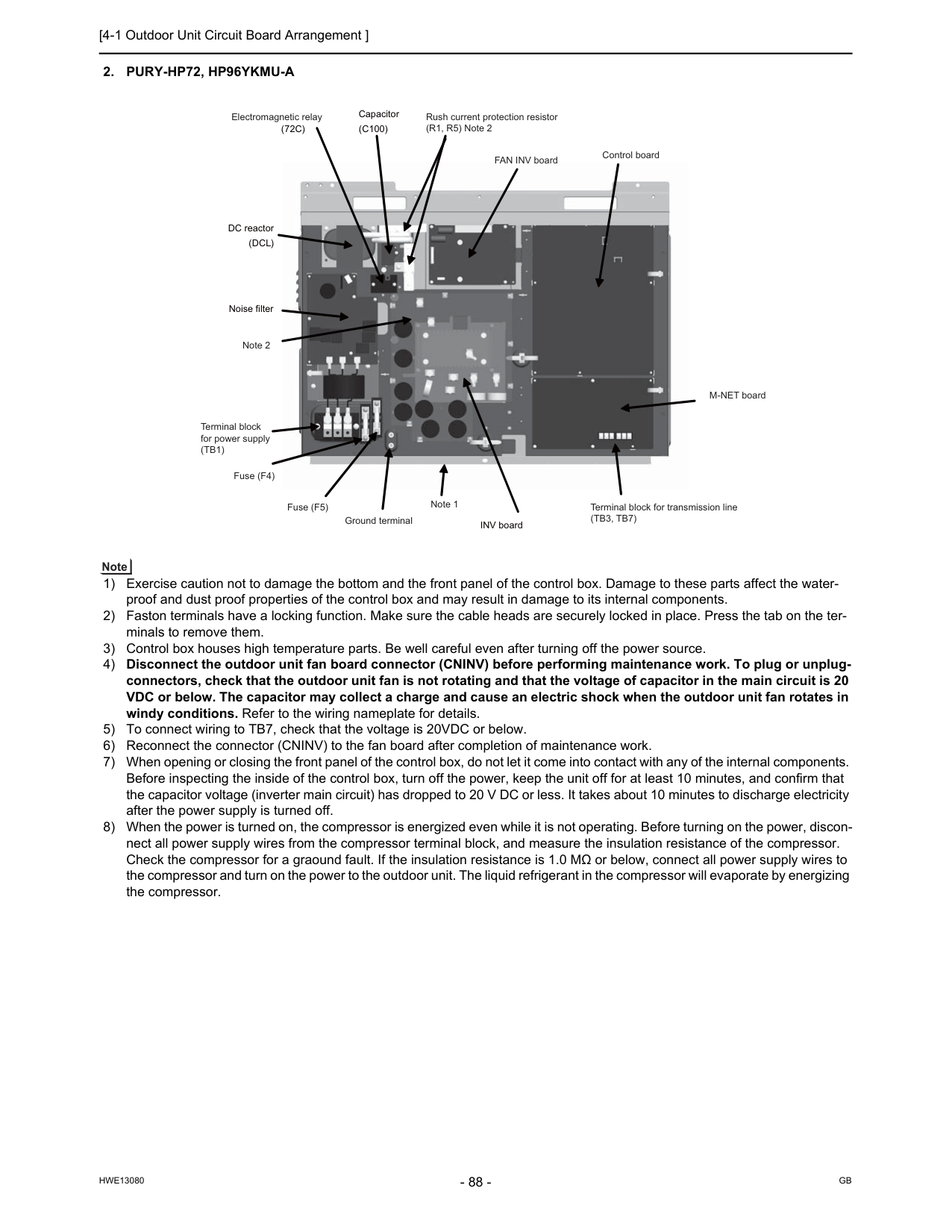
[4-1 Outdoor Unit Circuit Board Arrangement ]
Hwe13080
Gb
2. Pury-Hp72, Hp96Ykmu-A
1) Exercise caution not to damage the bottom and the front panel of the control box. Damage to these parts affect the water- proof and dust proof properties of the control box and may result in damage to its internal components. 2) Faston terminals have a locking function. Make sure the cable heads are securely locked in place. Press the tab on the ter- minals to remove them. 3) Control box houses high temperature parts. Be well careful even after turning off the power source. 4) Disconnect the outdoor unit fan board connector (CNINV) before performing maintenance work. To plug or unplug- connectors, check that the outdoor unit fan is not rotating and that the voltage of capacitor in the main circuit is 20 VDC or below. The capacitor may collect a charge and cause an electric shock when the outdoor unit fan rotates in windy conditions. Refer to the wiring nameplate for details. 5) To connect wiring to TB7, check that the voltage is 20VDC or below. 6) Reconnect the connector (CNINV) to the fan board after completion of maintenance work. 7) When opening or closing the front panel of the control box, do not let it come into contact with any of the internal components. Before inspecting the inside of the control box, turn off the power, keep the unit off for at least 10 minutes, and confirm that the capacitor voltage (inverter main circuit) has dropped to 20 V DC or less. It takes about 10 minutes to discharge electricity after the power supply is turned off. 8) When the power is turned on, the compressor is energized even while it is not operating. Before turning on the power, discon- nect all power supply wires from the compressor terminal block, and measure the insulation resistance of the compressor. Check the compressor for a graound fault. If the insulation resistance is 1.0 MΩ or below, connect all power supply wires to the compressor and turn on the power to the outdoor unit. The liquid refrigerant in the compressor will evaporate by energizing the compressor. INV board Noise filter DC reactor(Dcl)
(72C)
Capacitor(C100)
FAN INV board Control board Electromagnetic relay Note 2 Rush current protection resistor (R1, R5) Note 2 M-NET board Note 1 Ground terminal Fuse (F5) Fuse (F4) Terminal block for power supply(Tb1)
Terminal block for transmission line(Tb3, Tb7)
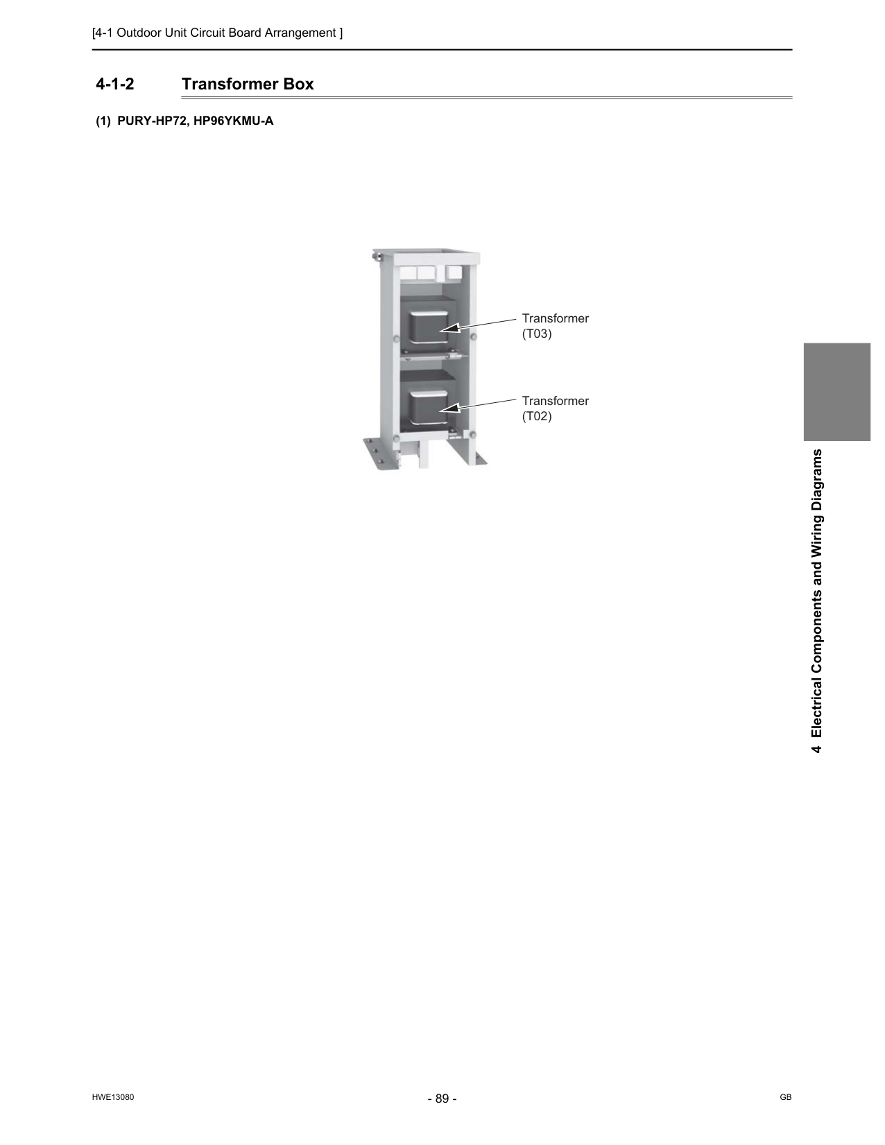
[4-1 Outdoor Unit Circuit Board Arrangement ]
Hwe13080
Gb
4 Electrical Components and Wiring Diagrams 4-1-2 Transformer Box(1) Pury-Hp72, Hp96Ykmu-A
Transformer(T03)
Transformer(T02)
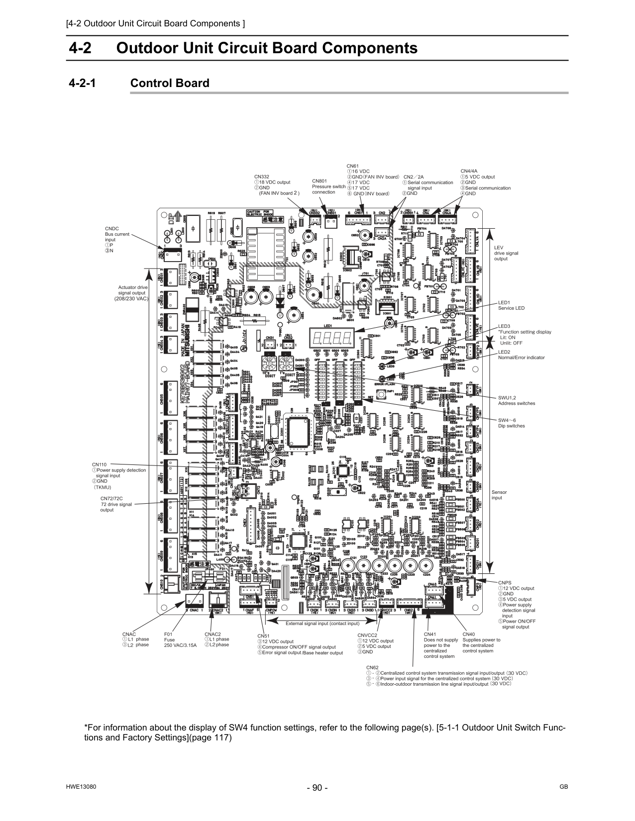
[4-2 Outdoor Unit Circuit Board Components ]
Hwe13080
Gb
4-2 Outdoor Unit Circuit Board Components 4-2-1 Control Board *For information about the display of SW4 function settings, refer to the following page(s). [5-1-1 Outdoor Unit Switch Func- tions and Factory Settings](page 117)(208/230 Vac)
/Base heater output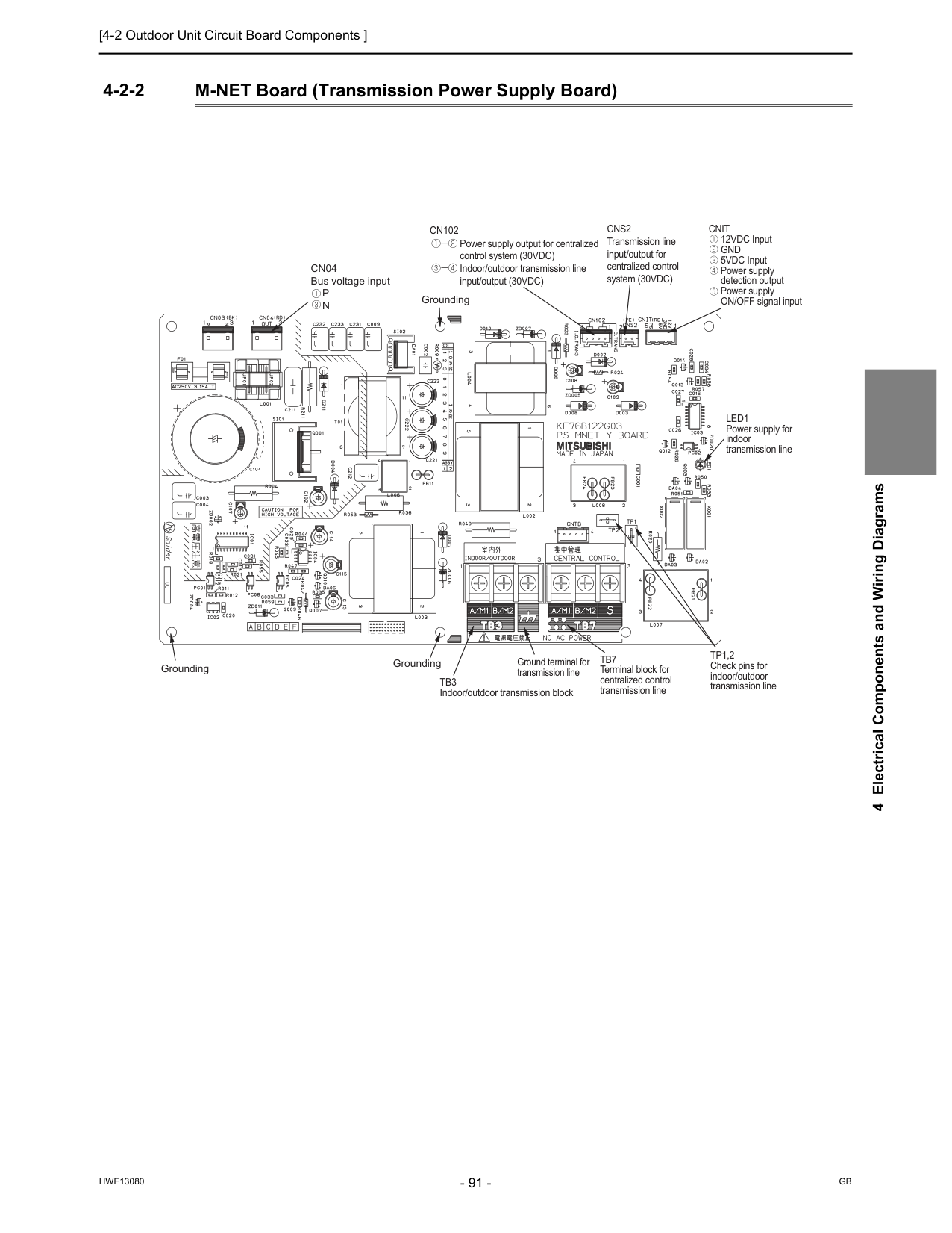
[4-2 Outdoor Unit Circuit Board Components ]
Hwe13080
Gb
4 Electrical Components and Wiring Diagrams 4-2-2 M-NET Board (Transmission Power Supply Board) Power supply output for centralized control system (30VDC) Indoor/outdoor transmission line input/output (30VDC)Cn102
Cns2
Transmission line input/output for centralized control system (30VDC)Cnit
12VDC InputGnd
5VDC Input Power supply detection output Power supply ON/OFF signal inputLed1
Power supply for indoor transmission lineTp1,2
Check pins for indoor/outdoor transmission lineTb7
Terminal block for centralized control transmission lineTb3
Indoor/outdoor transmission block Ground terminal for transmission line Grounding GroundingCn04
Bus voltage inputP
N
Grounding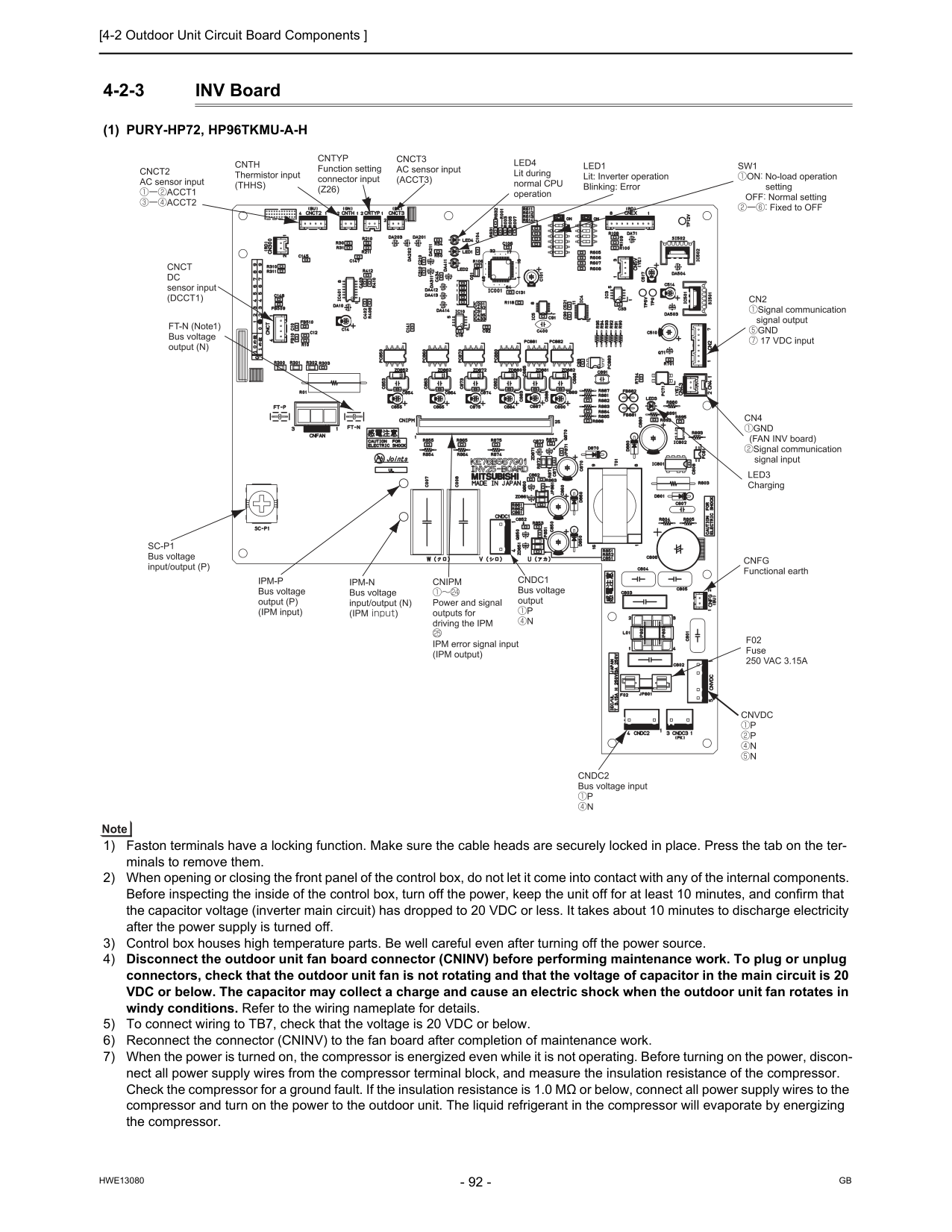
[4-2 Outdoor Unit Circuit Board Components ]
Hwe13080
Gb
4-2-3 INV Board(1) Pury-Hp72, Hp96Tkmu-A-H
1) Faston terminals have a locking function. Make sure the cable heads are securely locked in place. Press the tab on the ter- minals to remove them. 2) When opening or closing the front panel of the control box, do not let it come into contact with any of the internal components. Before inspecting the inside of the control box, turn off the power, keep the unit off for at least 10 minutes, and confirm that the capacitor voltage (inverter main circuit) has dropped to 20 VDC or less. It takes about 10 minutes to discharge electricity after the power supply is turned off. 3) Control box houses high temperature parts. Be well careful even after turning off the power source. 4) Disconnect the outdoor unit fan board connector (CNINV) before performing maintenance work. To plug or unplug connectors, check that the outdoor unit fan is not rotating and that the voltage of capacitor in the main circuit is 20 VDC or below. The capacitor may collect a charge and cause an electric shock when the outdoor unit fan rotates in windy conditions. Refer to the wiring nameplate for details. 5) To connect wiring to TB7, check that the voltage is 20 VDC or below. 6) Reconnect the connector (CNINV) to the fan board after completion of maintenance work. 7) When the power is turned on, the compressor is energized even while it is not operating. Before turning on the power, discon- nect all power supply wires from the compressor terminal block, and measure the insulation resistance of the compressor. Check the compressor for a ground fault. If the insulation resistance is 1.0 MΩ or below, connect all power supply wires to the compressor and turn on the power to the outdoor unit. The liquid refrigerant in the compressor will evaporate by energizing the compressor.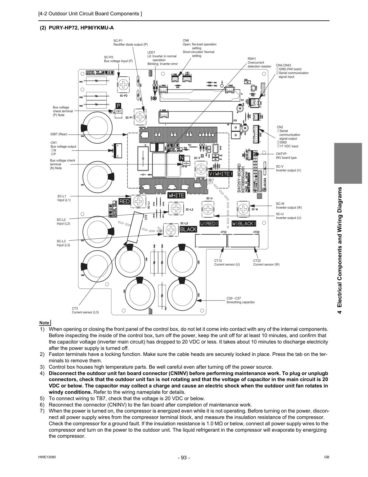
[4-2 Outdoor Unit Circuit Board Components ]
Hwe13080
Gb
4 Electrical Components and Wiring Diagrams(2) Pury-Hp72, Hp96Ykmu-A
1) When opening or closing the front panel of the control box, do not let it come into contact with any of the internal components. Before inspecting the inside of the control box, turn off the power, keep the unit off for at least 10 minutes, and confirm that the capacitor voltage (inverter main circuit) has dropped to 20 VDC or less. It takes about 10 minutes to discharge electricity after the power supply is turned off. 2) Faston terminals have a locking function. Make sure the cable heads are securely locked in place. Press the tab on the ter- minals to remove them. 3) Control box houses high temperature parts. Be well careful even after turning off the power source. 4) Disconnect the outdoor unit fan board connector (CNINV) before performing maintenance work. To plug or unplugb connectors, check that the outdoor unit fan is not rotating and that the voltage of capacitor in the main circuit is 20 VDC or below. The capacitor may collect a charge and cause an electric shock when the outdoor unit fan rotates in windy conditions. Refer to the wiring nameplate for details. 5) To connect wiring to TB7, check that the voltage is 20 VDC or below. 6) Reconnect the connector (CNINV) to the fan board after completion of maintenance work. 7) When the power is turned on, the compressor is energized even while it is not operating. Before turning on the power, discon- nect all power supply wires from the compressor terminal block, and measure the insulation resistance of the compressor. Check the compressor for a ground fault. If the insulation resistance is 1.0 MΩ or below, connect all power supply wires to the compressor and turn on the power to the outdoor unit. The liquid refrigerant in the compressor will evaporate by energizing the compressor.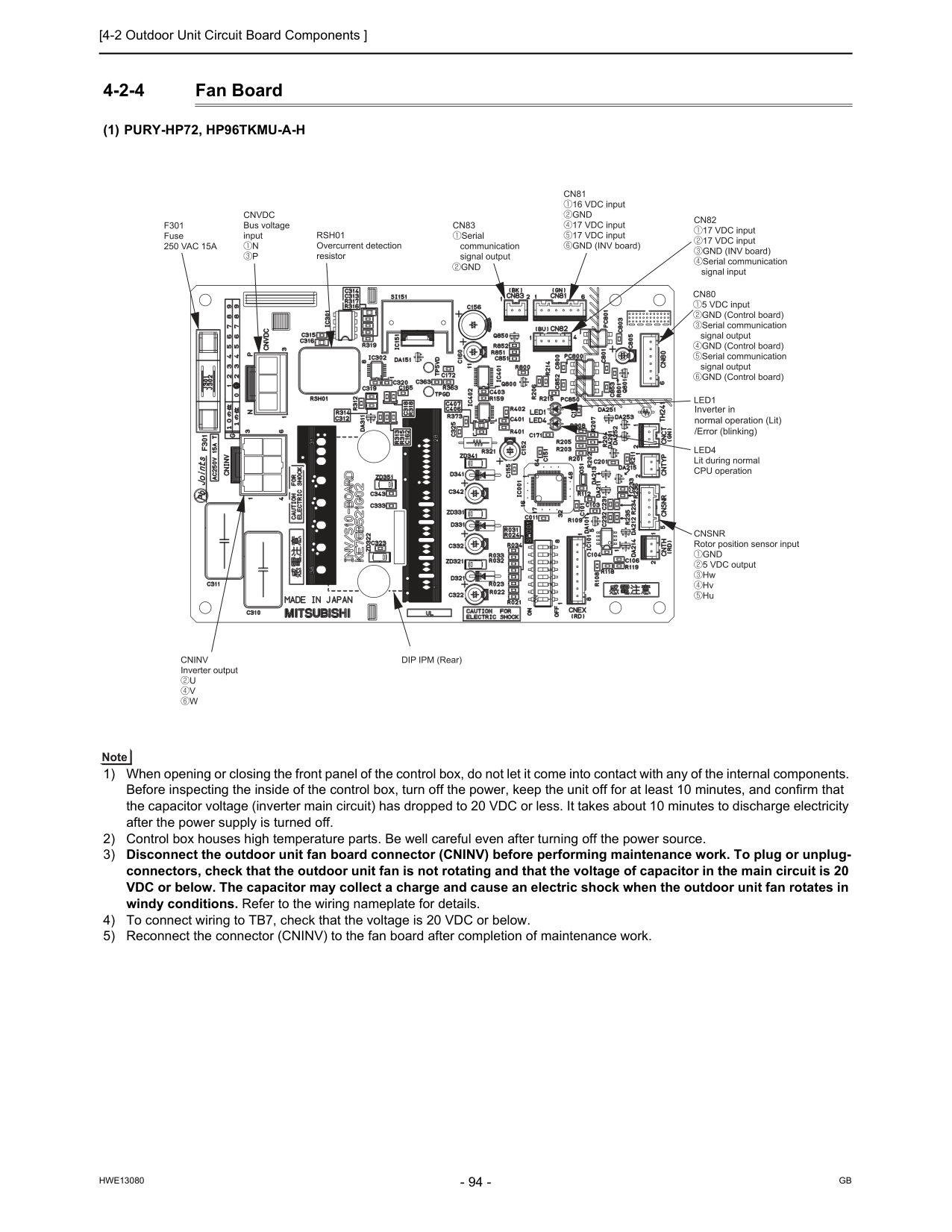
[4-2 Outdoor Unit Circuit Board Components ]
Hwe13080
Gb
4-2-4 Fan Board(1) Pury-Hp72, Hp96Tkmu-A-H
1) When opening or closing the front panel of the control box, do not let it come into contact with any of the internal components. Before inspecting the inside of the control box, turn off the power, keep the unit off for at least 10 minutes, and confirm that the capacitor voltage (inverter main circuit) has dropped to 20 VDC or less. It takes about 10 minutes to discharge electricity after the power supply is turned off. 2) Control box houses high temperature parts. Be well careful even after turning off the power source. 3) Disconnect the outdoor unit fan board connector (CNINV) before performing maintenance work. To plug or unplug- connectors, check that the outdoor unit fan is not rotating and that the voltage of capacitor in the main circuit is 20 VDC or below. The capacitor may collect a charge and cause an electric shock when the outdoor unit fan rotates in windy conditions. Refer to the wiring nameplate for details. 4) To connect wiring to TB7, check that the voltage is 20 VDC or below. 5) Reconnect the connector (CNINV) to the fan board after completion of maintenance work.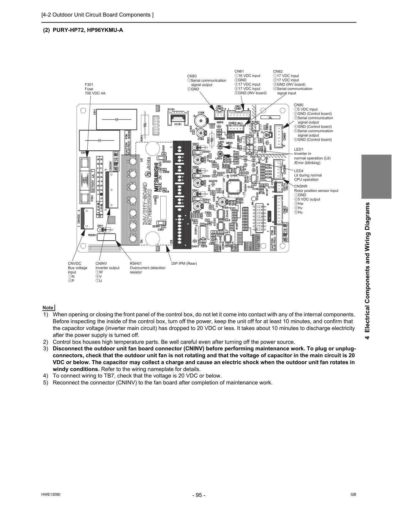
[4-2 Outdoor Unit Circuit Board Components ]
Hwe13080
Gb
4 Electrical Components and Wiring Diagrams(2) Pury-Hp72, Hp96Ykmu-A
1) When opening or closing the front panel of the control box, do not let it come into contact with any of the internal components. Before inspecting the inside of the control box, turn off the power, keep the unit off for at least 10 minutes, and confirm that the capacitor voltage (inverter main circuit) has dropped to 20 VDC or less. It takes about 10 minutes to discharge electricity after the power supply is turned off. 2) Control box houses high temperature parts. Be well careful even after turning off the power source. 3) Disconnect the outdoor unit fan board connector (CNINV) before performing maintenance work. To plug or unplug- connectors, check that the outdoor unit fan is not rotating and that the voltage of capacitor in the main circuit is 20 VDC or below. The capacitor may collect a charge and cause an electric shock when the outdoor unit fan rotates in windy conditions. Refer to the wiring nameplate for details. 4) To connect wiring to TB7, check that the voltage is 20 VDC or below. 5) Reconnect the connector (CNINV) to the fan board after completion of maintenance work.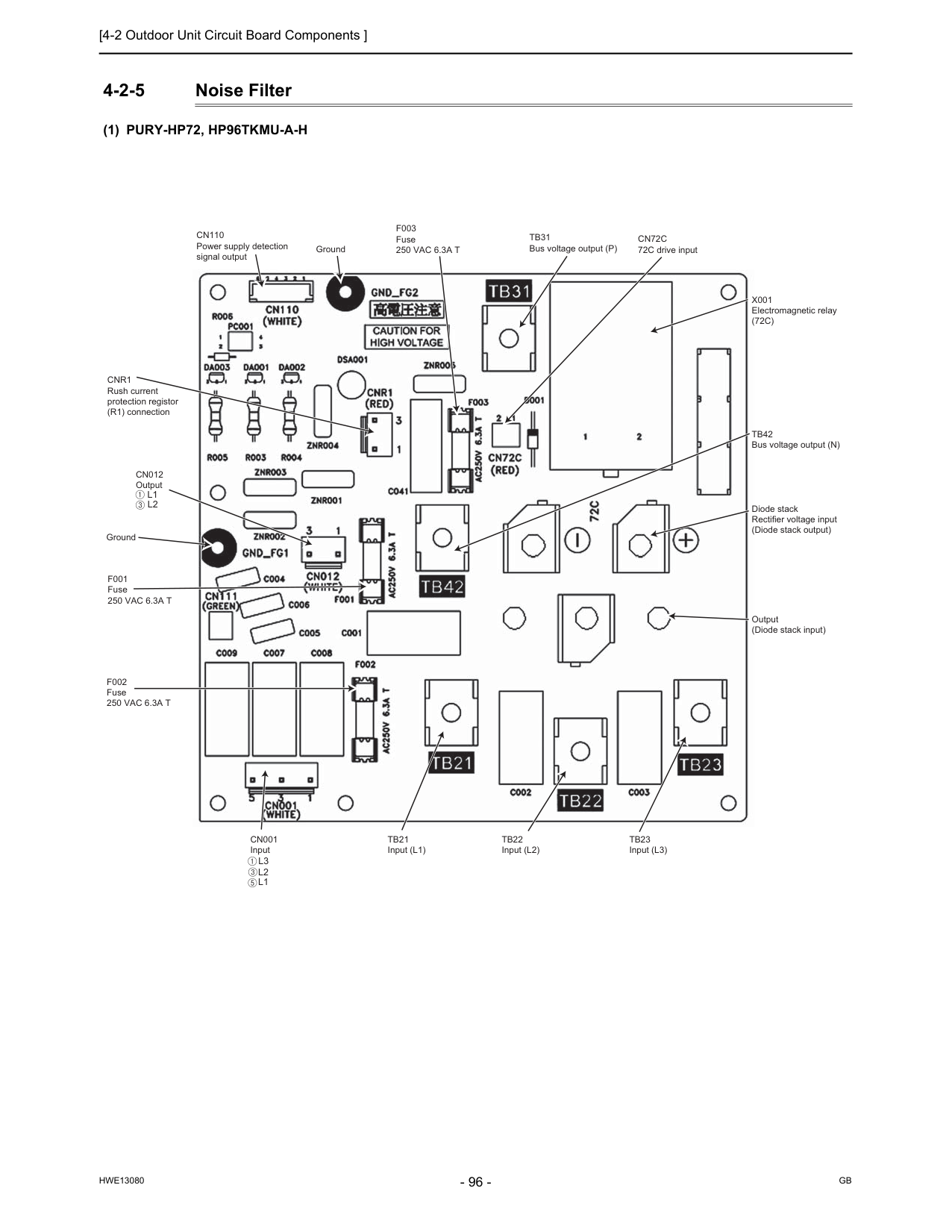
[4-2 Outdoor Unit Circuit Board Components ]
Hwe13080
Gb
4-2-5 Noise Filter(1) Pury-Hp72, Hp96Tkmu-A-H
Ground GroundTb31
Bus voltage output (P)Cn110
Power supply detection signal outputCn012
OutputCn001
InputCnr1
Rush current protection registor (R1) connectionTb21
Input (L1)Tb22
Input (L2)Tb23
Input (L3)F002
Fuse250 Vac 6.3A T
F001
Fuse250 Vac 6.3A T
Tb42
Bus voltage output (N)X001
Electromagnetic relay(72C)
Cn72C
72C drive inputF003
Fuse250 Vac 6.3A T
Diode stack Rectifier voltage input (Diode stack output) Output (Diode stack input)L3
L2
L1
L2
L1
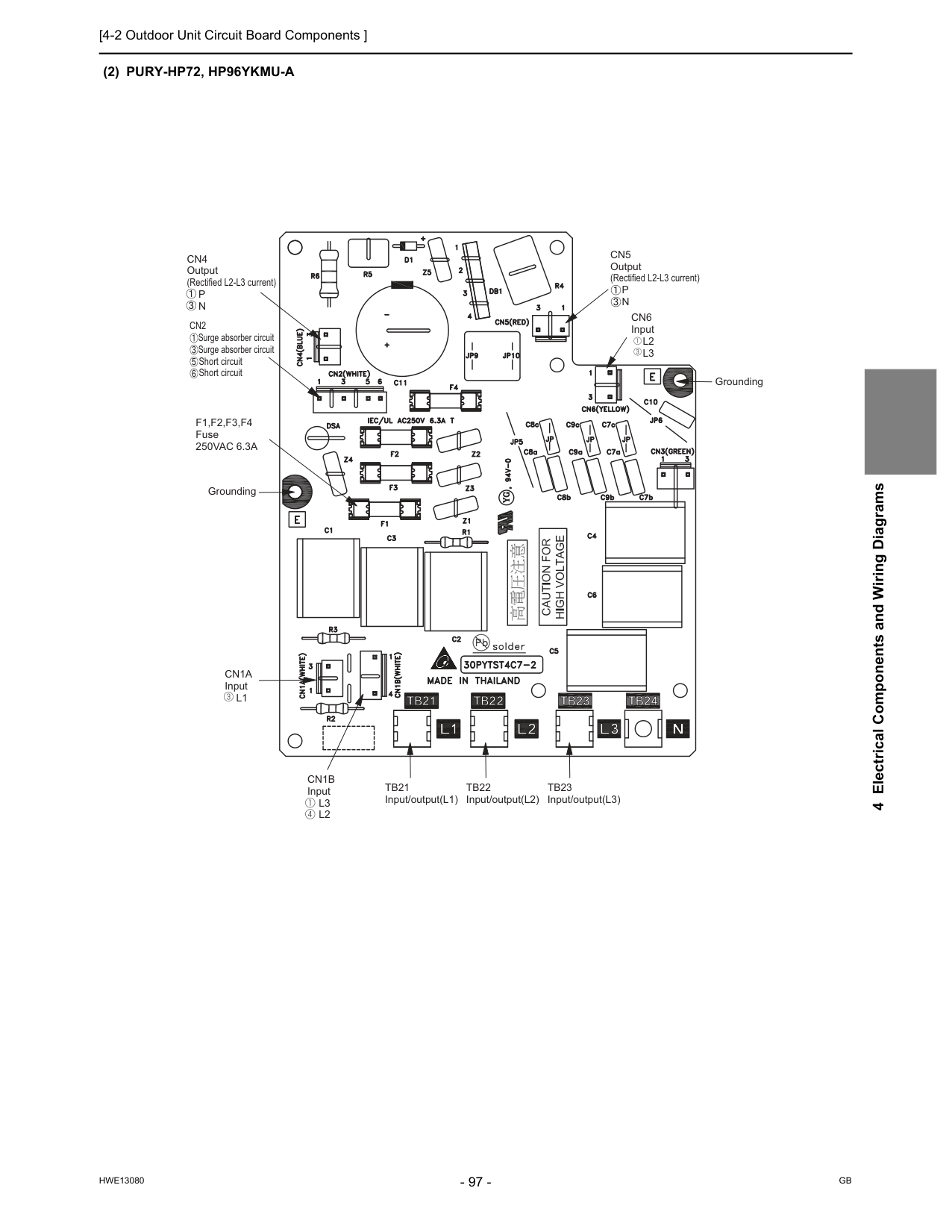
[4-2 Outdoor Unit Circuit Board Components ]
Hwe13080
Gb
4 Electrical Components and Wiring Diagrams(2) Pury-Hp72, Hp96Ykmu-A
Cn4
Output (Rectified L2-L3 current)P
N
Cn5
Output (Rectified L2-L3 current)P
N
Tb21
Input/output(L1)Tb22
Input/output(L2)Tb23
Input/output(L3)Cn1B
InputL3
L2
Cn1A
InputL1
GroundingF1,F2,F3,F4
Fuse250Vac 6.3A
Cn6
InputL2
L3
GroundingCn2
Surge absorber circuit Surge absorber circuit Short circuit Short circuit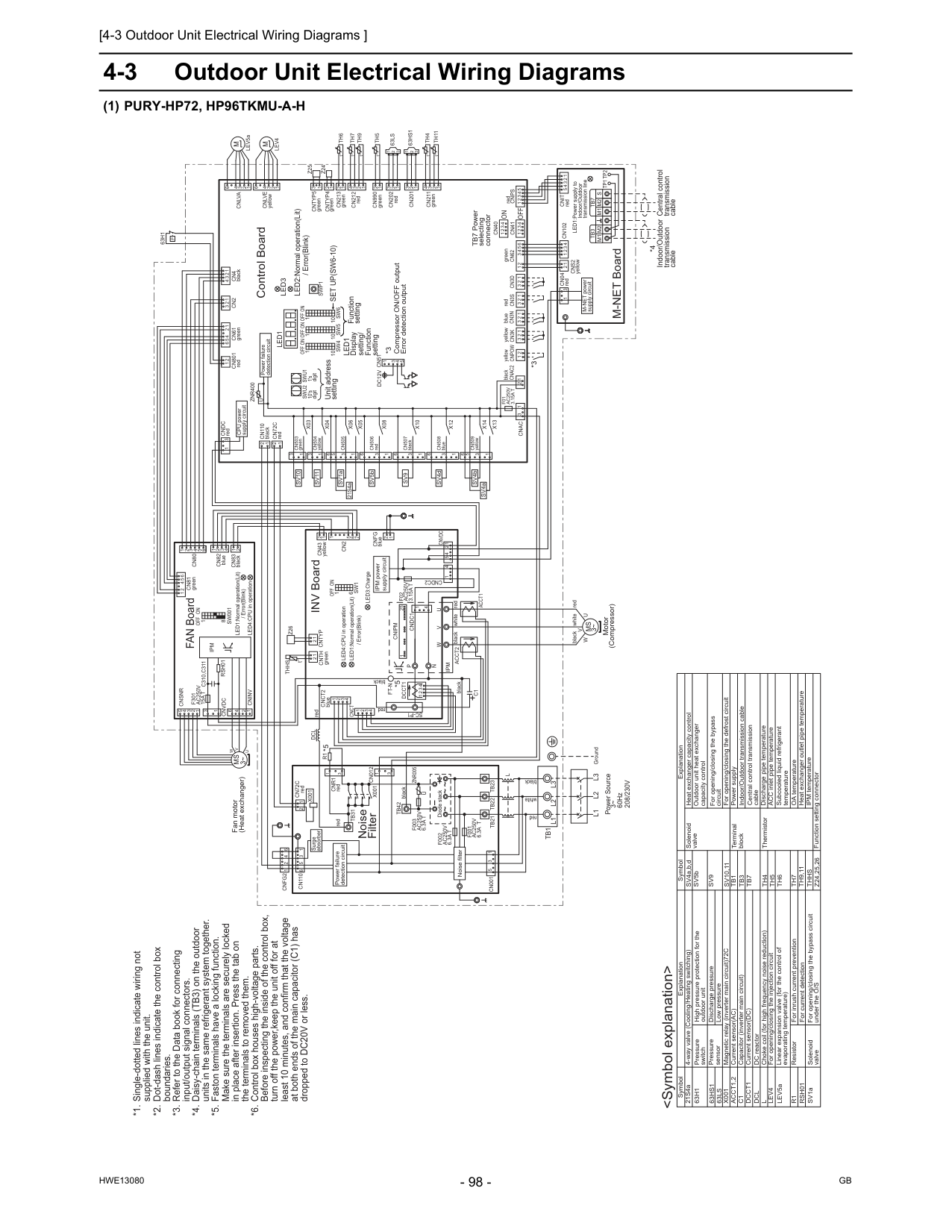
[4-3 Outdoor Unit Electrical Wiring Diagrams ]
Hwe13080
Gb
4-3 Outdoor Unit Electrical Wiring Diagrams(1) Pury-Hp72, Hp96Tkmu-A-H
For opening/closing the bypass circuit Terminal block Central control transmission cable Power supply Function setting connector IPM temperature Heat exchanger outlet pipe temperature ACC inlet pipe temperature Discharge pipe temperature ThermistorSv9
Tb1
Tb3
Tb7
Th4
Th5
Th6
Thhs
Z24,25,26
DC reactor Current sensor(AC) Low pressure Discharge pressure High pressure protection for the outdoor unit Pressure switch Pressure sensor Explanation Explanation 4-way valve (Cooling/Heating switching) For opening/closing the bypass circuit under the O/S Solenoid valve Solenoid valveDcl
LEV5aAcct1,2
63Ls
63Hs1
63H1
C1
Dcct1
SV1a SV5b Outdoor unit heat exchanger capacity control SV4a,b,d Subcooled liquid refrigerant temperature *1. Single-dotted lines indicate wiring notsupplied with the unit. *2. Dot-dash lines indicate the control box
boundaries. *3. Refer to the Data book for connecting
input/output signal connectors. *4. Daisy-chain terminals (TB3) on the outdoor
units in the same refrigerant system together. *5. Faston terminals have a locking function.
Make sure the terminals are securely locked
in place after insertion. Press the tab on
the terminals to removed them. *6. Control box houses high-voltage parts.
Before inspecting the inside of the control box,
turn off the power,keep the unit off for at
least 10 minutes, and confirm that the voltage
at both ends of the main capacitor (C1) has
dropped to DC20V or less.
X001
For inrush current preventionR1
Choke coil (for high frequency noise reduction)L
Indoor/Outdoor transmission cable Magnetic relay (inverter main circuit)72C Heat exchanger capacity control Linear expansion valve (for the control of evaporating temperature) Resistor For current detectionRsh01
Capacitor (inverter main circuit) Current sensor(DC) For opening/closing the injection circuitLev4
For opening/closing the defrost circuitSv10,11
OA temperatureTh7
Th9,11
GroundL3
L2
L1
X14
X13
6 1 3 5 1 2 redCnps
1 3 2 1Tp1 Tp2
Tb3
2 3Tb7
M1 M2
M1 M2 S
5 1 2 3 4 1 2 t° 1 2 1 3 2 3 4 6 1 2 2Cn82
blue 1 3 4Cn83
black 3 1 6X12
1 3Cn508
blueCn4
black 2 3 1 tSw001
1 3 °Cn2
7 1 2 1 3 3 1 4 3 2 2 3 1 1Th4
t 4 ° 1 1Cn211
green 2 3 1 2 3 3 2 1 6Cnsnr
5 4 3 2 1U
V
W
Fan motor (Heat exchanger)Ms
3~ 4 1 6Cninv
2Sw1
1 6Off On
3 2 2 3 Power failure detection circuit red 1 Surge absorber 2 3 1Tb1
L3
L2
L1
2 1 INV Board °t 2L
yellowCnpow
t° 6 5 4 5Cnvdc
4Cndc2
1Acct2
F02
Ac250V
3.15A T
C1
Ipm
4X10
On
X08
Unit address setting LED3:Charge 6 3 1 6F001
Ac250V
6.3A T
F002
Ac250V
6.3A T
Rsh01
Cn001
5 3 1Tb22
Tb23
Tb21
Diode stack~ ~ ~ 1 2 3 4 3 greenCn62
Cn990
greenCntyp4
Cn201
Z25
1Th5
2Swu2
Led1
Sw6
10 Control BoardCn40
63Hs1
Cn41
Th7
1 5 5 4 3 1Sw4
Led3
2 LEV5a 3Set Up(Sw6-10)
V
M
Off
Cn506
red yellowCn3K
*3 Compressor ON/OFF output Error detection outputDc12V Cn51
SV5bW
blueCn3N
1 3 3 4 TB7 Power selecting connectorCnvdc
Ipm
5 1 2 6On
Off
M-NET power supply circuit 1 2 M-NET Board Power failure detection circuit Indoor/Outdoor transmission cableOn
1's digitCn102
1 4 1U
10's digitOff
LED2:Normal operation(Lit) / Error(Blink) yellowCndc
redMs
3~ 2Th6
U
LED1:Power supply to Indoor/Outdoor transmission lineZnr400
Central control transmission cableOn
Off
Motor (Compressor) redCn3S
1Cn04
redCn43
yellowCn61
greenCn202
red 8 / Error(Blink) *4 2P
63H1
4 1Sw5
10 5Cn3D
1 CPU power supply circuit blackCnac2
1 *3On
Off
10Swu1
N
Cn212
redW
U
P
6Cndc1
1 4V
1Cn80
25F301
Ac250V
15A T
Cnipm
Cntyp5
green LED4:CPU in operationFt-N
LED1:Normal operation(Lit) / Error(Blink)Cn801
redSwp1
Cn012
1 3 FAN Board63Ls
U
Znr005
Z24
2Cn507
black 3F003
Ac250V
6.3A T
Tb42
6 4X001
Cn213
green black *5Sv9
Function settingLed1
Display setting/ Function setting red LED4:CPU in operation 5 1Sc-P1
Dcl
blackCn72C
red 3 1Dcct1
1 2 1 4 1Cnlva
1Cnr1
red blackF01
Ac250V
3.15A T
Tb31
R1
white redCnit
redX001
1 2 Power Source 3~ 60Hz208/230V
Cnct
red whiteAcct1
5 6Cn110
Noise filter 3 1 6 4 1 2 IPM power supply circuitCnfg2
Noise Filter black 4 3 2 1Cnct2
blue 4 3 2 1X05
X06
3 5 1 6Cn505
1 3 1 2Cnfg
blue 1 2 black red white *5 black redThhs
°tZ26
Cntyp
2Cnth
green 2 1Cn110
black 2 1 red 1 2 1Cnac
Cn81
green 1 2 5 1 3 4 4 SV4a 4Cn2
C310,C311
SV4d SV1a SV4b 21S4a 1 2 3 4 6M
Cnlve
yellowLev4
Th9
Th11
t° 2Cn509
yellowCns2
3 2 3 1X04
yellowCn504
Sv11
3 1X03
greenCn503
Sv10
Cn72C
green LED1:Normal operation(Lit)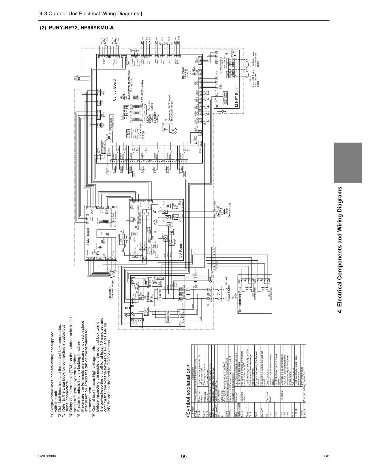
[4-3 Outdoor Unit Electrical Wiring Diagrams ]
Hwe13080
Gb
4 Electrical Components and Wiring Diagrams(2) Pury-Hp72, Hp96Ykmu-A
For opening/closing the bypass circuit Terminal block Central control transmission cable Indoor/Outdoor transmission cable Power supply Function setting connector IPM temperature OA temperature ACC inlet pipe temperature Discharge pipe temperature ThermistorSv9
Tb1
Tb3
Tb7
Th4
Th5
Th6
Th7
Thhs
Z24,25
DC reactor Current sensor(AC) Magnetic relay(inverter main circuit) Low pressure Discharge pressure High pressure protection for the outdoor unit Pressure switch Pressure sensor Explanation 4-way valve(Cooling/Heating switching) For opening/closing the bypass circuit under the O/S Solenoid valveDcl
LEV5aCt12,22,3
72C
63Ls
63Hs1
63H1
with the unit. *2. Dot-dash lines indicate the control box boundaries. *3. Refer to the Data book for connecting input/output
signal connectors. *4. Daisy-chain terminals (TB3) on the outdoor units in the
same refrigerant system together. *5. Faston terminals have a locking function.
Make sure the terminals are securely locked in place
after insertion. Press the tab on the terminals to
removed them. *6. Control box houses high-voltage parts.
Before inspecting the inside of the control box,turn off
the power,keep the unit off for at least 10 minutes, and
confirm that the voltage between FT-P and FT-N on
INV Board has dropped to DC20V or less. For inrush current prevention Resistor
R1,5
Heat exchanger capacity control SV4a,b,dL
Capacitor (inverter main circuit)C30~C37
For current detectionRsh01,Rsh1
Linear expansion valve (for the control of evaporating temperature) Choke coil (for high frequency noise reduction)Lev4
For opening/closing the injection circuit For opening/closing the defrost circuitSv10,11
Heat exchanger outlet pipe temperatureTh9,11
1 2L3
redCnps
1 3 2 1Tp1 Tp2
Tb3
2 3Tb7
M1 M2
M1 M2 S
1 5 1 2 3 4 1 2 t° 1 2 1 3 2 3 4 6 3 6 1 5 3 1 2 2Cn82
blue 1 3 4Cn83
blackL1
L2
3 1 Fan motor (Heat exchanger)U
V
W
Cninv
7 1 4 3 4Cn4
black 1 1 3 2 3 1 t 3Sw001
1 4 °Cn2
1 1 2 1 3 3 1 4 3 2 2 3 1 1Cnsnr
Th4
t 4 ° 1 1 1Cn211
green 2 3 1 2 3 3 2 1U
5 Transformer BoxCntr3
3 4Cntr2
T02
(Transformer) 2 2 3 4T03
(Transformer) 1 1 2 5 4 3 2 1 1 3 2 1 2 3 1 2 3 1Cn6
2 1 °t 2 yellowCnpow
t° 1 6 5 4X10
On
X08
Unit address settingCt12
Cn5
redD1
R4
Z5
Cntr1 1
2L1 L2 L2
3L3
4 5 6 7 8Rsh01
white Ground 1 2 3 4 3 white red black black white redF4
Ac600V
6A F
F5
Ac600V
6A F
greenCn62
Cn990
greenCntyp4
F4
Ac250V
6.3A T
R5
Cn201
Z25
1Th5
2Swu2
Led1
Sw6
10 Control BoardCn40
63Hs1
Cn41
Th7
1 5 2 3 4 1Sw4
Led3
5 LEV5a 3 3Set Up(Sw6-10)
Sc-V
Ct22
Sc-U
V
Cn4
blue redM
Off
t blackCn506
redCntyp2
black 6 yellowCn3K
*3 Compressor ON/OFF output Error detection outputTb21
Dc12V Cn51
SV5bCn1A
U
Cn2
blueCn3N
1 3 + 3 4Tb1
Cn1B
TB7 Power selecting connectorCnvdc
1Ipm
2 5 6L3
Dcl
black72C
white red 2 6On
Off
M-NET power supply circuit 1 2 M-NET Board Power failure detection circuit Indoor/Outdoor transmission cable INV Board redTb23
L2
L1
+On
1's digitThhs
Cn102
C31,C33,
C35,C37
1 4 1W
10's digitOff
LED2:Normal operation(Lit) / Error(Blink) yellowCndc
red redMs
3~ 2C100
*5Th6
U
LED1:Power supply to Indoor/Outdoor transmission lineZnr400
+ black Central control transmission cable *6Sc-L1
On
Off
Ft-N
R30,R32,
R34
Motor (Compressor) redCn3S
1Cn04
redCn43
1Sc-P2
P
Cn61
greenCn202
redC30,C32,
C34,C36
8N
Cn1
LED1: Normal operation(Lit) / Error(Blink) *4Sc-W
Sc-L3
2P
63H1
4 1Sw5
10 5Cn3D
1 CPU power supply circuit blackCnac2
1 *3On
Off
10Swu1
whiteCn212
redSc-L2
6 2Cn80
F301
Dc700V
4A T
Cntyp5
green LED4:CPU in operation LED1:Normal operation(Lit) / Error(Blink)Cn801
red 5 °Ipm
4Sc-P1
Ft-P
black redDb1
Ct3
C1
Cntyp
black blackTb22
Swp1
Rsh1
R6
C11
FAN Board63Ls
Znr1
U
L
Noise FilterZ24
2Cn507
black 3 3 6 4Cn213
greenCn6
yellowSv9
Function settingLed1
Display setting/ Function setting72C
Noise filter Noise filter 6 7 red Surge absorber 1 2 1Cnlva
1F01
Ac250V
3.15A T
Ms
3~ white black 1Cnit
redL1
L2
L3
R31,R33,
R35
3 4 1R1,R5
X05
X06
3 5 1 6Cn505
1 3X13
SV4dX14
X12
1 6 3Cn508
blue 1 6 3Cnac
Cn81
green 1 2 5 1 3 4 SV4a SV4b 4 4Cn2
C310,C311
SV1a 21S4a 5 Power Source 3~ 60Hz460V
1 2 3 4 6M
Cnlve
Lev4
yellowTh9
Th11
t° 2Cns2
Cn509
yellowX04
3 1 yellowSv11
Cn504
X03
3 1 greenCn503
Sv10
greenCn72
yellow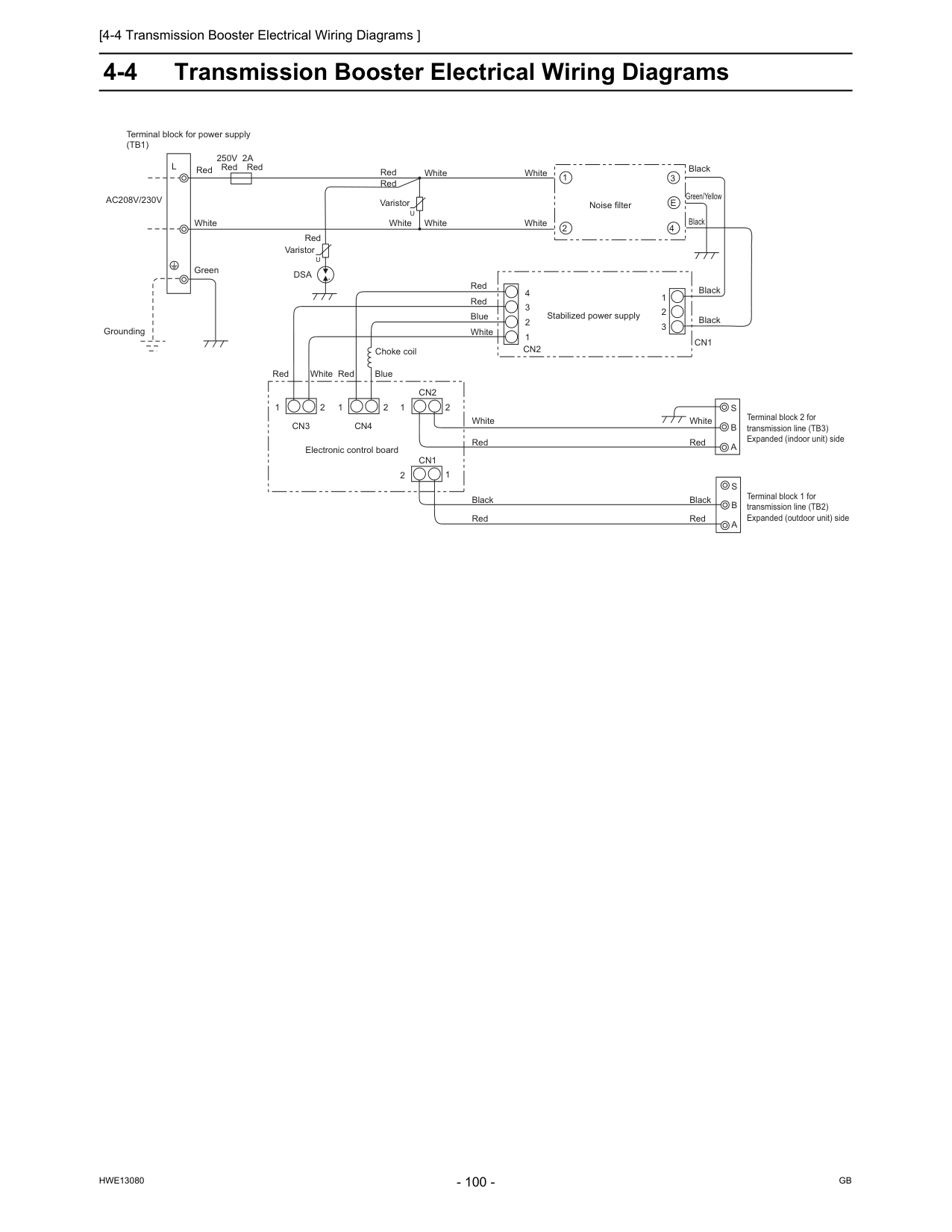
[4-4 Transmission Booster Electrical Wiring Diagrams ]
Hwe13080
Gb
4-4 Transmission Booster Electrical Wiring DiagramsAc208V/230V
L
Red Red Red White Green250V 2A
Grounding Red Red RedU
U
White White White White White White Blue Red RedDsa
White White Blue Red Red Red Red Varistor Varistor Noise filter Stabilized power supply 4 3 2 1 1 2 3Cn2
Cn1
Black Black Black Black Green/Yellow 1 2 3E
4 Choke coil 1 2Cn3
1 2 1 2Cn4
Cn2
1 2Cn1
Electronic control board Black White Red Red BlackS
B
A
S
B
A
Terminal block 2 for transmission line (TB3) Expanded (indoor unit) side Terminal block 1 for transmission line (TB2) Expanded (outdoor unit) side Terminal block for power supply(Tb1)
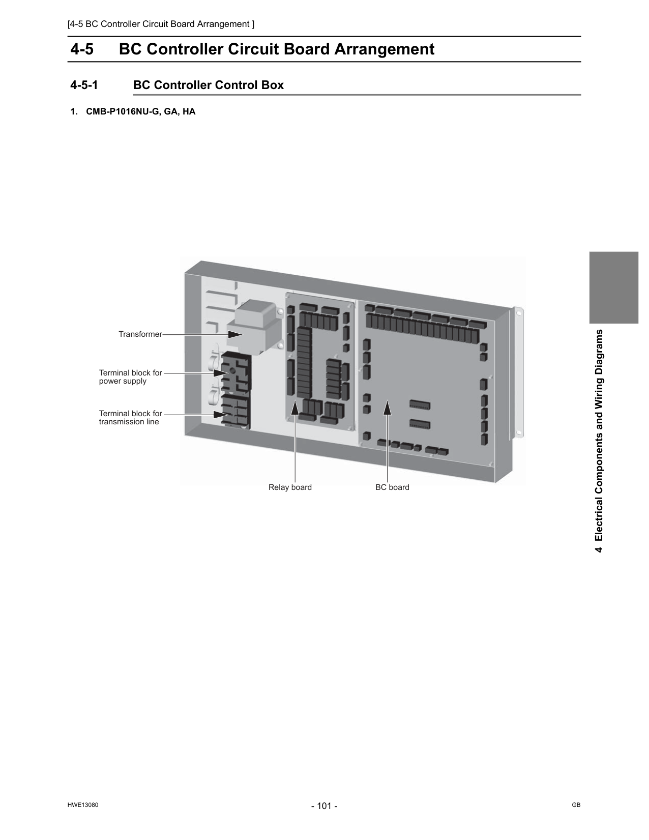
[4-5 BC Controller Circuit Board Arrangement ]
Hwe13080
Gb
4 Electrical Components and Wiring Diagrams 4-5 BC Controller Circuit Board Arrangement 4-5-1 BC Controller Control Box1. Cmb-P1016Nu-G, Ga, Ha
Relay board Transformer Terminal block for transmission line BC board Terminal block for power supply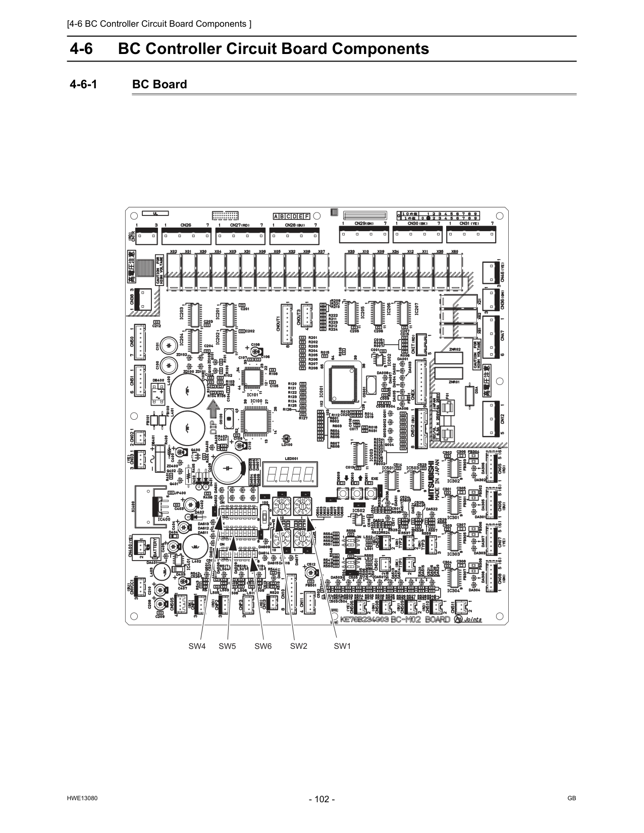
[4-6 BC Controller Circuit Board Components ]
Hwe13080
Gb
4-6 BC Controller Circuit Board Components 4-6-1 BC BoardSw1
Sw2
Sw5
Sw6
Sw4
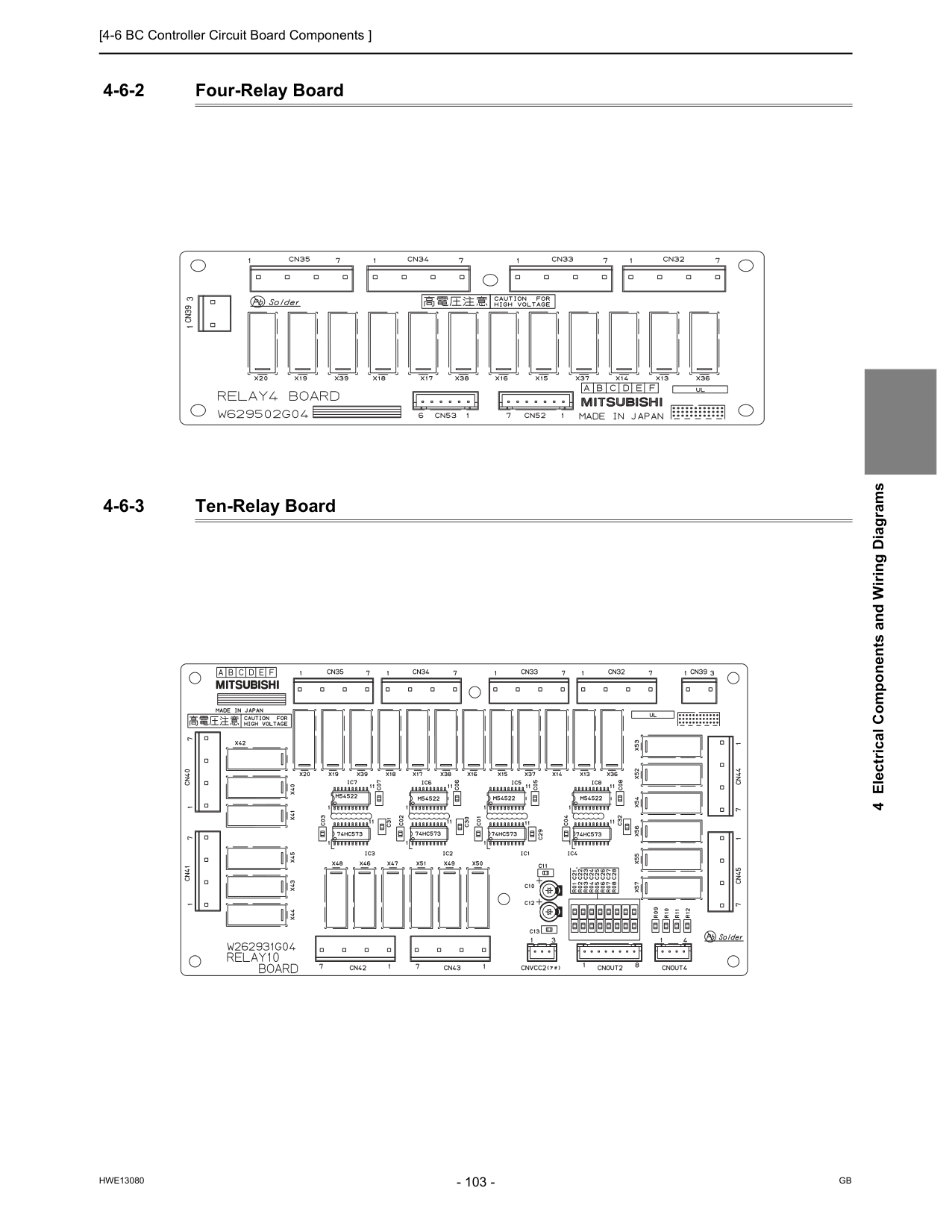
[4-6 BC Controller Circuit Board Components ]
Hwe13080
Gb
4 Electrical Components and Wiring Diagrams 4-6-2 Four-Relay Board 4-6-3 Ten-Relay Board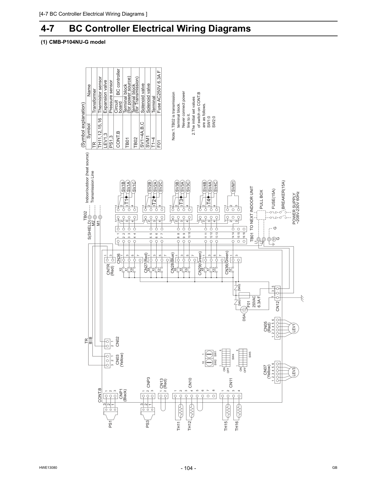
[4-7 BC Controller Electrical Wiring Diagrams ]
Hwe13080
Gb
4-7 BC Controller Electrical Wiring Diagrams (1) CMB-P104NU-G model (Red)Cntr
Znr02
Znr01
L2
X21
CN36(Green) 3 1 3 2 1 3 2 1Svm1
CN29(Green)X33
X7
X8
1 3 5 7 1 4 3 2 1 14 16 15Sv4A
Sv4C
Sv4B
11 12 13 14 15 16 11 12 13 4 3 2 1 1 1 1 CN28(Blue) CN27(Red)X32
X5
X6
X31
X3
X4
X30
X1
X2
1 3 5 7 1 3 5 7 1 3 5 7Sv1B
Sv1A
Sv1C
5 6 7 8 9 4 3 2 4 3 2 1 4 3 2 1 2 3 4 6 5 7 3 4 2Sv2A
Sv2C
Sv3C
Sv2B
Sv3B
Sv3A
3 4 1 2 10 3 2 4 8 9 10 4 3 2 1L1
M1
M2
S(Shield)
Lev3
Tb01
Lev1
1 2 3 4 5 6Ps3
Ps1
Th16
Th15
Th12
Th11
Cn07
Cn11
Cn10
Cn13
Cn03
1 2 3 2 1 1 2 3 4 8 7 6 5 4 3 2 1 1 2Cnp3
3 2 1Cnp1
3Cn02
2 1Cont.B
1 2 3 4 5 6Cn05
3 5 1Cn12
1 3Cn26
Tb02
Tr
Svm1
Solenoid valve Fuse AC250V 6.3A FF01
TerminalT1~4
Terminal block (for Transmission)Tb02
Terminal block (for power source)Tb01
Solenoid valveSv1~4A,B,C
Expansion valve Thermistor sensor Transformer Name SymbolTr
Th11,12,15,16
Lev1,3
Ps1,3
Pressure sensorCont.B
Note:1.TB02 is transmission terminal block. Never connect power line to it. 2.The initial set values of switch on CONT.B are as follows.Sw1:0
Sw2:0
Indoor/outdoor (heat source) Transmission Line ~208V-230V 60HzPower Supply
Breaker(15A)
Fuse(15A)
Pull Box
To Next Indoor Unit
G
T4
T1
T3
T2
1 3 1 3G
2 2 8 1On
Sw4
8Off
Sw5
1Off
On
Dsa
(Yellow) (Red) (Yellow) (Red) (Black)F01
250Vac
6.3A F
10 1Sw1
Sw2
Circuit board (Symbol explanation) BC controller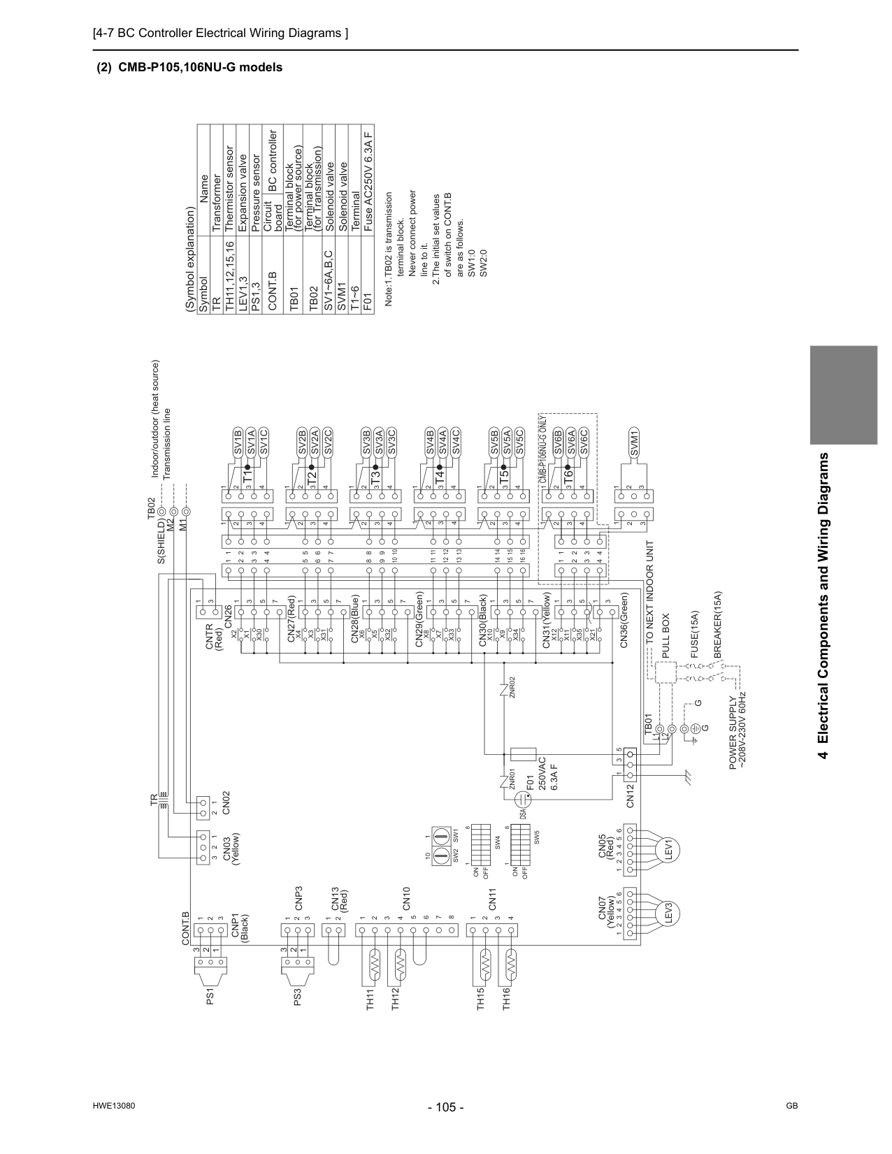
[4-7 BC Controller Electrical Wiring Diagrams ]
Hwe13080
Gb
4 Electrical Components and Wiring Diagrams (2) CMB-P105,106NU-G models CN36(Green)L2
L1
Znr02
CN29(Green) CN28(Blue) CN27(Red)Znr01
Cn05
Cn07
S(Shield)
M1
M2
Tb02
X21
1 3Svm1
3 2 1 2 3 1Tr
Cn26
3Cntr
1Cn12
1 5 3 6 5 4 3 2 1Cont.B
1 2Cn02
3Cnp1
1 2 3Cnp3
2 1 1 2 3 4 5 6 7 8 4 3 2 1 1 2 3 2 1Cn03
Cn13
Cn10
Cn11
Th11
Th12
Th15
Th16
Ps1
Ps3
6 5 4 3 2 1Tb01
Lev3
Lev1
1 2 3 4 10 9 8 4 2 3 10 2 1 4 3Sv3A
Sv3B
Sv2B
Sv3C
Sv2C
Sv2A
2 4 3 7 5 6 4 3 2 1 2 3 4 1 2 3 4 2 3 4 9 8 7 6 5Sv1C
Sv1A
Sv1B
7 5 3 1 7 5 3 1 7 5 3 1X2
X1
X30
X4
X3
X31
X6
X5
X32
1 1 1 1 2 3 4 13 12 11 16 15 14 13 12 11Sv5A
Sv5C
Sv4B
Sv5B
Sv4C
Sv4A
15 16 14 1 2 1 4 2 3 4 3 4 3 2 1 4 3 2 1Sv6C
Sv6A
Sv6B
1 2 3 4 1 2 3 4 1 2 3 4 1 5 3 1 7 5 3 1 7 5 3 1X8
X7
X33
X10
X9
X34
X12
X11
X35
CN30(Black) CN31(Yellow) Solenoid valveSvm1
Cont.B
Pressure sensorTr
Th11,12,15,16
Lev1,3
Ps1,3
Symbol Name Transformer Thermistor sensor Expansion valveSv1~6A,B,C
Solenoid valveTb01
Terminal block (for power source)Tb02
Terminal block (for Transmission)T1~6
TerminalF01
Fuse AC250V 6.3A F Note:1.TB02 is transmission terminal block. Never connect power line to it. 2.The initial set values of switch on CONT.B are as follows.Sw1:0
Sw2:0
To Next Indoor Unit
Pull Box
Fuse(15A)
Breaker(15A)
Power Supply
~208V-230V 60HzG
G
Indoor/outdoor (heat source) Transmission line 2 2 3 1 3 1T2
T3
T1
T6
T4
T5
On
Off
1Sw5
Off
8Sw4
On
1 8 (Yellow) (Red)Dsa
(Red) (Yellow) (Red) (Black)Sw2
Sw1
1 10Cmb-P106Nu-G Only
F01
250Vac
6.3A F
BC controller (Symbol explanation) Circuit board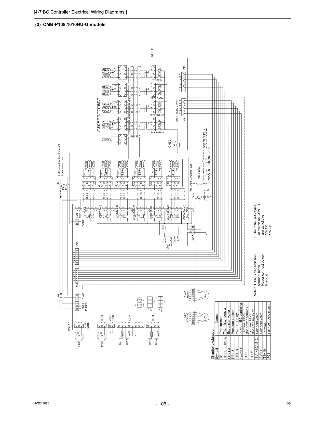
[4-7 BC Controller Electrical Wiring Diagrams ]
Hwe13080
Gb
(3) CMB-P108,1010NU-G models 2.The initial set values of switch on CONT.B are as follows.Sw1:0
Sw2:0
Pressure sensorTr
Th11,12,15,16
Lev1,3
Ps1,3
Sv1~10A,B,C
Symbol Name Transformer Thermistor sensor Expansion valve Solenoid valveTb01
Terminal block (for power source)Tb02
Terminal block (for Transmission)Cont.B
T1~10
Terminal Fuse AC250V 6.3A FF01
Solenoid valveSvm1
Cn51
Cn53
6 5 4 3 2 11 2 3 4 5 6 6 5 4 3 2 1 (Red)Znr01
Znr02
L1
Tb01
L2
CN31(Yellow) CN30(Black) CN29(Green) CN28(Blue) CN27(Red)Cn05
Cn07
Cn13
Cnp1
M1
M2
Tb02
S(Shield)
X21
3 1 CN36(Green)Cn12
3 3 3 1 5 7 1 3 5 7 1 3 5 7 1 3 7 5X20
X19
X39
X38
X17
X18
X16
X15
X37
X36
X13
X14
CN34(Black) CN33(Red)Cn32
CN35(Blue) 16 16 13 14 15 9 10 11 12 5 6 7 8 4 4 5 6 8 7 9 12 11 10 15 14 13Sv10C
Sv9C
Sv8C
Sv7C
Sv10A
Sv9A
Sv8A
Sv7A
Sv10B
Sv9B
Sv8B
Sv7B
4 3 2 1 4 3 2 1 4 3 2 1 4 3 2 1 4 3 2 1 4 3 2 1 4 3 2 1 4 3 2 1X30
X1
X2
1 3 5 4 3 2 1Sv1B
Sv1A
Sv1C
1 2 3 4 3 2 4 1 3 2 4 1X35
X11
X12
X34
X9
X10
X33
X7
X8
X32
X5
X6
X31
X3
X4
7 1 3 5 7 1 3 5 7 1 3 5 7 1 3 5 7 1 3 5 7 1 1 1 4 3 2 4 3 2 4 3 2 1 4 3 2Sv2C
Sv2A
Sv2B
Sv3C
Sv3A
Sv3B
Sv4C
Sv4A
Sv4B
Sv5B
Sv5A
Sv5C
1 1 1 1 2 2 2 2 3 3 3 3 4 4 4 4 11 12 13 8 9 10 5 6 7 14 15 16 8 9 10 11 12 13 5 6 7 14 15 16 1 2 1 2 3 3 4 3 2 1 4 3 2 1Sv6C
Sv6A
Sv6B
7 6 5 4 3 2 1Cn39
3 1Cn52
Cont.B
6 5 4 3 2 1 6 5 4 3 2 1Lev3
Lev1
1 2 3 1 2 3Cnp3
2 1 1 2 3 4 5 6 7 8 4 3 2 1 1 2 3 2 1Cn03
Cn02
Cn10
Cn11
Th11
Th12
Th15
Th16
Tr
Ps1
Ps3
Cn50
7 6 5 4 3 2 11 2 3 4 5 6 7 1 3 5 1 3Cn38
Cn26
3 1Cntr
1 2 3 1 2 3Svm1
Rel.B
Note:1.TB02 is transmission terminal block. Never connect power line to it.G
G
To Next Indoor Unit
Pull Box
Fuse(15A)
Breaker(15A)
Power Supply
~208V-230V 60Hz Indoor/outdoor (heat source) Transmission lineT10
T9
T8
T7
T1
T5
T4
T3
T2
T6
1 3 2 3 1 2 1 8On
Off
Sw5
Sw4
On
Off
1 8 (Symbol explanation) Circuit board BC controllerRel.B
RelayCmb-P1010Nu-G Only
(Yellow)Dsa
(Red) (Yellow) (Red) (Black)F01
250Vac
6.3A F
Cmb-P1010Nu-G Only
10 1Sw1
Sw2
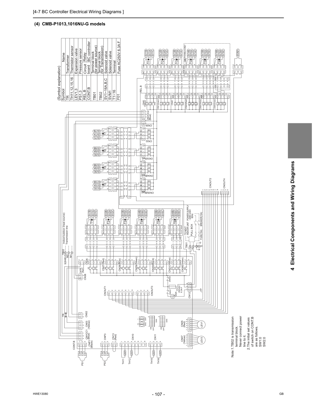
[4-7 BC Controller Electrical Wiring Diagrams ]
Hwe13080
Gb
4 Electrical Components and Wiring Diagrams (4) CMB-P1013,1016NU-G modelsZnr01
Znr02
L1
L2
Tb01
M1
M2
Tb02
S(Shield)
Cn32
CN33(Red) CN34(Black) CN35(Blue) CN36(Green) CN31(Yellow) CN30(Black) CN29(Green) CN28(Blue) CN27(Red) (Red) (Blue) (Yellow)Cn07
Cn05
Cn13
Lev1
Lev3
X21
3 1 2 1Cnvcc1
3Cnvcc2
3 1 2Cont.B
Cn39
1 3 1 3 5Cn12
Cnout3
Cnout1
1 3 1 2 3 8 7 6 5 4 3 2 1 4Cnout2
Cnout4
6 5 4 3 2 1 6 5 4 3 2 1 1 2 3Cnp1
1 2 3Cnp3
2 1 1 2 3 4 5 6 7 8 4 3 2 1 1 2 3 2 1Cn03
Cn02
Cn10
Cn11
Th11
Th12
Th15
Th16
Tr
Cn38
Cn26
3 1Cntr
4 1 2 3 4 5 6 7 8 3 2 1Ps1
Ps3
CN44(Yellow) CN45(Green) CN41(Green) CN43(Red) (Yellow)Sv1B
Sv1A
Sv1C
5 6 7 8 9 10 11 12 13 14 15 16 3 2 4 8 9 10 11 12 13 3 2 4 5 6 7 14 15 16 4 3 2Sv2C
Sv2A
Sv2B
Sv3C
Sv3A
Sv3B
Sv4C
Sv4A
Sv4B
Sv5B
Sv5A
Sv5C
4 3 2 1 4 3 2 1 4 3 2 1 4 3 2 1 4 3 2 4 3 2 1 4 3 2 1 4 3 2 1 4 3 2 1Sv6B
Sv6A
Sv6C
1 2 3 4 1 2 3 4 3 3 2 1 2 1X35
X11
X12
X34
X9
X10
X33
X7
X8
X32
X5
X6
X31
X3
X4
X30
X1
X2
5 3 1 7 5 3 1 7 5 3 1 7 5 3 1 7 5 3 1 7 5 3 1 1 1 1 1Sv7A
Sv7B
Sv7C
Sv8B
Sv8A
Sv8C
Sv9B
Sv9A
Sv9C
Sv10B
Sv10A
Sv10C
16 16 13 14 15 9 10 11 12 5 6 7 8 4 4 5 6 8 7 9 12 11 10 15 14 13 1 2 3 4 1 2 3 4 1 2 3 4 1 2 3 4 1 2 3 4 1 2 3 4 1 2 3 4 1 2 3 4 7 5 3 1 3 3X14
X13
X36
X37
X15
X16
X38
X39
X17
X19
X18
X20
7 5 3 1 7 5 3 1 7 5 3 1Cn40
Svm1
2 3 2 1 3 1Rel.B
4 5 6 8 9 7 10 12 11 13 15 14 16 3 4 2 1Sv11B
Sv11A
Sv11C
1 3 2 8 9 10 11 12 13 3 2 4 1 5 6 7 14 15 16 4 3 2 1Sv12C
Sv12A
Sv12B
Sv13C
Sv13A
Sv13B
Sv14C
Sv14A
Sv14B
Sv15B
Sv15A
Sv15C
4 3 2 1 4 3 2 1 4 3 2 1 4 3 2 1 4 3 2 1 4 3 2 1 4 3 2 1 4 3 2 1 4 3 2 1Sv16B
Sv16A
Sv16C
1 2 3 4 1 2 3 4 3 4 2 1X51
X55
X56
X52
X53
X57
X54
7 7 5 3 1 7 5 3 1X45
X42
X43
X40
X44
X48
X47
X46
X50
X49
Cn42
5 7 7 5 3 1 7 5 3 1 5 3 1 3X41
1 Solenoid valveSvm1
Cont.B
Terminal block (for Transmission)Tb02
Terminal block (for power source)Tb01
Solenoid valve Expansion valve Thermistor sensor Transformer Name SymbolSv1~16A,B,C
Tr
Th11,12,15,16
Lev1,3
Ps1,3
Pressure sensor TerminalT1~16
F01
Fuse AC250V 6.3A F Note:1.TB02 is transmission terminal block. Never connect power line to it. 2.The initial set values of switch on CONT.B are as follows.Sw1:0
Sw2:0
Indoor Unit
G G
Pull Box
Fuse(15A)
Breaker(15A)
Power Supply
~208V-230V
60HzTo Next
Indoor/outdoor (heat source) Transmission line 2 2 1 3 1 3T1
T5
T4
T3
T2
T6
T10
T9
T8
T7
T11
T15
T14
T13
T12
T16
1On
Sw4
8Off
Sw5
Off
On
8 1Dsa
(Blue) (Yellow) (Red) (Red) (Black) 10 1Sw1
Sw2
F01
250Vac
6.3A F
Cmb-P1016Nu-G Only
RelayRel.B
BC controller Circuit board (Symbol explanation)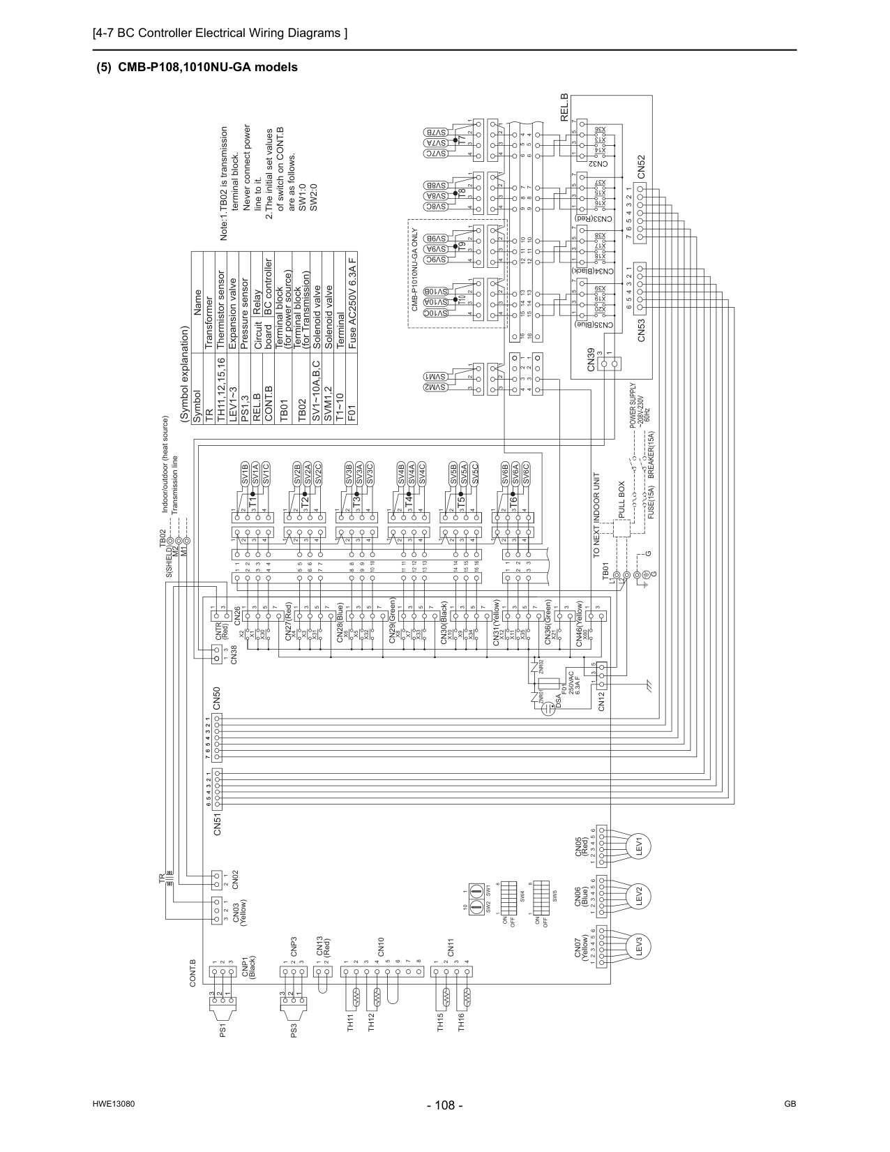
[4-7 BC Controller Electrical Wiring Diagrams ]
Hwe13080
Gb
(5) CMB-P108,1010NU-GA models Note:1.TB02 is transmission terminal block. Never connect power line to it. 2.The initial set values of switch on CONT.B are as follows.Sw1:0
Sw2:0
F01
Fuse AC250V 6.3A FT1~10
Terminal Solenoid valveSvm1,2
Cont.B
Terminal block (for Transmission)Tb02
Terminal block (for power source)Tb01
Solenoid valve Expansion valve Thermistor sensor Transformer Name SymbolSv1~10A,B,C
Tr
Th11,12,15,16
Lev1~3
Ps1,3
Pressure sensor 6 5 4 3 2 1Cn53
6 5 4 3 2 11 2 3 4 5 6Cn51
(Yellow)Cn03
Tb01
L2
L1
CN36(Green) CN30(Black) CN31(Yellow) CN29(Green) CN28(Blue) CN27(Red) (Red)Cntr
Znr01
Znr02
M1
M2
Tb02
S(Shield)
Cn06
Cn05
Cn07
Cn13
Cnp1
Lev2
1 2 3 4 5 6 1 3Cn26
Cn38
3 1Cn12
5 3 1 7 6 5 4 3 2 11 2 3 4 5 6 7Cn50
Ps3
Ps1
Tr
Th16
Th15
Th12
Th11
Cn11
Cn10
Cn02
1 2 3 2 1 1 2 3 4 8 7 6 5 4 3 2 1 1 2Cnp3
3 2 1 3 2 1Lev1
Lev3
1 2 3 4 5 6 1 2 3 4 5 6Cont.B
Sv6B
Sv6A
Sv6C
1 2 3 4 1 2 3 4 3 3 2 1 2 1 16 15 14 7 6 5 13 12 11 10 9 8 16 15 14 7 6 5 10 9 8 13 12 11 4 4 4 4 3 3 3 3 2 2 2 2 1 1 1 1Sv5C
Sv5A
Sv5B
Sv4B
Sv4A
Sv4C
Sv3B
Sv3A
Sv3C
Sv2B
Sv2A
Sv2C
2 3 4 1 2 3 4 2 3 4 2 3 4 1 1 1 7 5 3 1 7 5 3 1 7 5 3 1 7 5 3 1 7 5 3 1 7X4
X3
X31
X6
X5
X32
X8
X7
X33
X10
X9
X34
X12
X11
X35
1 4 2 3 1 4 2 3 4 3 2 1Sv1C
Sv1A
Sv1B
1 2 3 4 5 3 1X2
X1
X30
X60
X21
CN46(Yellow) 3 1 3 1 3 1 CN33(Red) CN34(Black) CN35(Blue)Cn39
Rel.B
Cn52
1 2 3 4 5 6 7 1 2 3 4 1 2 3 4 1 2 3 4 1 2 3 4 1 2 3 4 1 2 3 4 1 2 3 4 1 2 3 4Sv7B
Sv8B
Sv9B
Sv10B
Sv7A
Sv8A
Sv9A
Sv10A
Sv7C
Sv8C
Sv9C
Sv10C
13 14 15 10 11 12 9 7 8 6 5 4 4 8 7 6 5 12 11 10 9 15 14 13 16 16Cn32
X14
X13
X36
X37
X15
X16
X18
X17
X38
X39
X19
X20
5 7 1 7 5 1 7 5 3 1 7 5 1 3 3 3 1 2 3 4 4 1 2 3 1 2 3 1 2 3Svm1
Svm2
60Hz~208V-230V
Power Supply
Breaker(15A)
Pull Box
Fuse(15A)
To Next Indoor Unit
G
G
Indoor/outdoor (heat source) Transmission line 2 1 3 2 3 1T6
T2
T3
T4
T5
T1
T7
T8
T9
T10
8 1Off
On
Sw4
Sw5
Off
On
8 1 RelayRel.B
BC controller Circuit board (Symbol explanation)Cmb-P1010Nu-Ga Only
Dsa
(Blue) (Red) (Yellow) (Red) (Black)Sw2
Sw1
1 10F01
250Vac
6.3A F
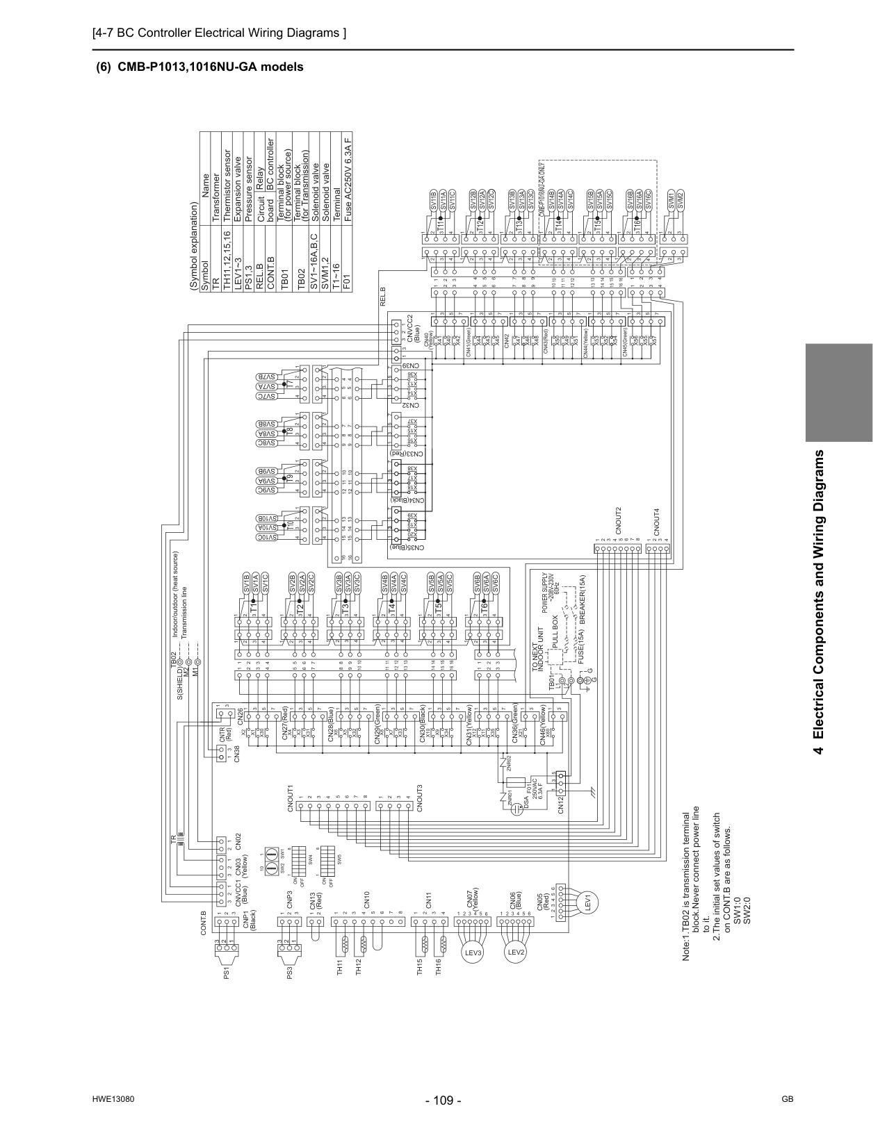
[4-7 BC Controller Electrical Wiring Diagrams ]
Hwe13080
Gb
4 Electrical Components and Wiring Diagrams (6) CMB-P1013,1016NU-GA modelsCntr
(Red) CN41(Green)Cn40
(Yellow) CN34(Black) CN33(Red) CN35(Blue)Znr01
Znr02
Cn06
5 4 3 2 1Lev2
Cn07
Cn13
Cnp1
(Blue)Cnvcc1
(Yellow)Cn03
M1
M2
Tb02
S(Shield)
6 5 4 3 2 1Lev3
2 1 3Cnvcc2
3 1 2Cont.B
Cn39
1 3Cnout3
Cnout1
1 3 1 2 3 1 2 3Cnp3
2 1 1 2 3 4 5 6 7 8 4 3 2 1 1 2 3 2 1Cn02
Cn10
Cn11
Th11
Th12
Th15
Th16
Tr
Cn38
Cn26
3 1 4 1 2 3 4 5 6 7 8 3 2 1Ps1
Ps3
X45
X42
X43
X40
X44
X47
X46
Cn42
X41
Sv1B
Sv1A
Sv1C
5 6 7 8 9 10 11 12 13 14 15 16 3 2 4 8 9 10 11 12 13 3 2 4 5 6 7 14 15 16 4 3 2Sv2C
Sv2A
Sv2B
Sv3C
Sv3A
Sv3B
Sv4C
Sv4A
Sv4B
Sv5B
Sv5A
Sv5C
4 3 2 1 4 3 2 1 4 3 2 1 4 3 2 1 4 3 2 4 3 2 1 4 3 2 1 4 3 2 1 4 3 2 1Sv6B
Sv6A
Sv6C
1 2 3 4 1 2 3 4 3 3 2 1 2 1 CN31(Yellow) CN30(Black) CN29(Green) CN28(Blue) CN27(Red)X35
X11
X12
X34
X9
X10
X33
X7
X8
X32
X5
X6
X31
X3
X4
X30
X1
X2
7 5 3 1 7 5 3 1 7 5 3 1 7 5 3 1 7 5 3 1 7 5 3 1 1 1 1 1Sv7A
Sv7B
Sv7C
Sv8B
Sv8A
Sv8C
Sv9B
Sv9A
Sv9C
Sv10B
Sv10A
Sv10C
16 16 13 14 15 9 10 11 12 5 6 7 8 4 4 5 6 8 7 9 12 11 10 15 14 13 1 2 3 4 1 2 3 4 1 2 3 4 1 2 3 4 1 2 3 4 1 2 3 4 1 2 3 4 1 2 3 4Cn32
7 5 3 1 3 3X14
X13
X36
X37
X15
X16
X38
X39
X17
X19
X18
X20
7 5 3 1 7 5 3 1 7 5 3 1 1 CN36(Green)X21
CN45(Green) CN44(Yellow) CN43(Red)Rel.B
4 5 6 8 9 7 10 12 11 13 15 14 16 3 4 2 1Sv11B
Sv11A
Sv11C
1 3 2 8 9 10 11 12 13 3 2 4 1 5 6 7 14 15 16 4 3 2 1Sv12C
Sv12A
Sv12B
Sv13C
Sv13A
Sv13B
Sv14C
Sv14A
Sv14B
Sv15B
Sv15A
Sv15C
4 3 2 1 4 3 2 1 4 3 2 1 4 3 2 1 4 3 2 1 4 3 2 1 4 3 2 1 4 3 2 1 4 3 2 1Sv16B
Sv16A
Sv16C
1 2 3 4 1 3 4 3 4 2 1X51
X55
X56
X52
X53
X57
X54
7 7 5 3 1 7 5 3 1X48
X50
X49
5 7 7 5 3 1 7 5 3 1 5 3 1 3 1Svm2
Svm1
3 2 2 3 1 1 2Cn05
6 5 4 3 2 1Lev1
L2
L1
Tb01
1 3 5Cn12
1 2 3 8 7 6 5 4 3 2 1 4Cnout2
Cnout4
3 3 1 CN46(Yellow)X60
Cont.B
Terminal block (for Transmission)Tb02
Terminal block (for power source)Tb01
Solenoid valve Expansion valve Thermistor sensor Transformer Name SymbolSv1~16A,B,C
Tr
Th11,12,15,16
Lev1~3
Ps1,3
Pressure sensorSvm1,2
T1~16
Terminal Solenoid valveF01
Fuse AC250V 6.3A F Note:1.TB02 is transmission terminal block.Never connect power line to it. 2.The initial set values of switch on CONT.B are as follows.Sw1:0
Sw2:0
6 Indoor/outdoor (heat source) Transmission line 2 2 1 3 1 3T1
T5
T4
T3
T2
T6
T10
T9
T8
T7
T11
T15
T14
T13
T12
T16
Pull Box
Fuse(15A) Breaker(15A)
Indoor Unit
To Next
Power Supply
~208V-230V
60HzG G
1On
Sw4
8Off
Sw5
Off
On
8 1 (Blue)Dsa
(Blue) (Yellow) (Red) (Black) 10 1Sw1
Sw2
Cmb-P1016Nu-Ga Only
(Red)F01
250Vac
6.3A F
RelayRel.B
BC controller Circuit board (Symbol explanation)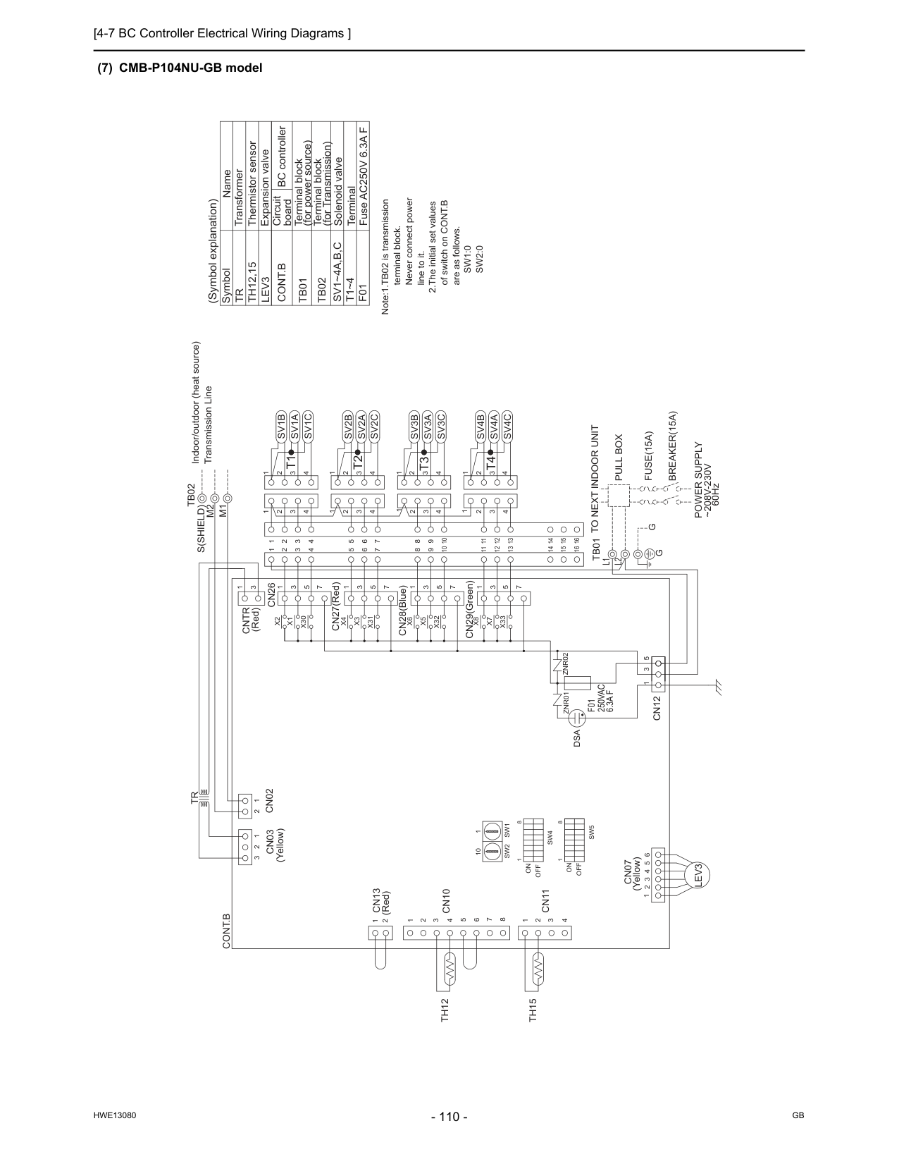
[4-7 BC Controller Electrical Wiring Diagrams ]
Hwe13080
Gb
(7) CMB-P104NU-GB modelZnr02
Znr01
CN29(Green) CN28(Blue) CN27(Red)Cntr
(Red)Cn07
L1
L2
Tb01
Cn13
Cn03
M1
M2
S(Shield)
Tb02
X33
X7
X8
1 3 5 7 1 4 3 2 1 14 16 15Sv4A
Sv4C
Sv4B
11 12 13 14 15 16 11 12 13 4 3 2 1 1 1 1X32
X5
X6
X31
X3
X4
X30
X1
X2
1 3 5 7 1 3 5 7 1 3 5 7Sv1B
Sv1A
Sv1C
5 6 7 8 9 4 3 2 4 3 2 1 4 3 2 1 2 3 4 6 5 7 3 4 2Sv2A
Sv2C
Sv3C
Sv2B
Sv3B
Sv3A
3 4 1 2 10 3 2 4 8 9 10 4 3 2 1Lev3
1 2 3 4 5 6Th15
Th12
Cn11
Cn10
1 2 3 2 1 1 2 3 4 8 7 6 5 4 3 2 1 1 2Cn02
Cont.B
3 5 1Cn12
1 3Cn26
Tr
Fuse AC250V 6.3A FF01
TerminalT1~4
Terminal block (for Transmission)Tb02
Terminal block (for power source)Tb01
Solenoid valveSv1~4A,B,C
Expansion valve Thermistor sensor Transformer Name SymbolTr
Th12,15
Lev3
Cont.B
Note:1.TB02 is transmission terminal block. Never connect power line to it. 2.The initial set values of switch on CONT.B are as follows.Sw1:0
Sw2:0
G
G
Fuse(15A)
Breaker(15A)
Power Supply
~208V-230V
60HzTo Next Indoor Unit
Pull Box
Indoor/outdoor (heat source) Transmission LineT4
T1
T3
T2
8 1On
Sw4
8Off
Sw5
1Off
On
Dsa
(Yellow) (Red) (Yellow)F01
250Vac
6.3A F
10 1Sw1
Sw2
Circuit board (Symbol explanation) BC controller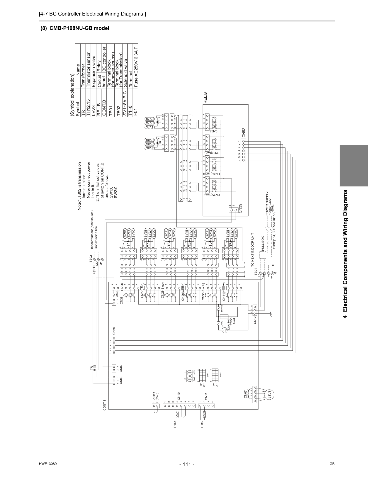
[4-7 BC Controller Electrical Wiring Diagrams ]
Hwe13080
Gb
4 Electrical Components and Wiring Diagrams (8) CMB-P108NU-GB model CN31(Yellow) CN33(Red) CN34(Black) CN35(Blue) CN30(Black) CN29(Green) CN28(Blue) CN27(Red)Tb01
L1
L2
Znr02
Znr01
Cn07
Cn13
(Red)M1
M2
S(Shield)
Tb02
Cn12
3 1 5 7 1 3 5 7 1 3 5 7 1 3 7 5X20
X19
X39
X38
X17
X18
X16
X15
X37
X36
X13
X14
Cn32
16 16 13 14 15 9 10 11 12 5 6 7 8 4 4 5 6 8 7 9 12 11 10 15 14 13Sv8C
Sv7C
Sv8A
Sv7A
Sv8B
Sv7B
4 3 2 1 4 3 2 1 4 3 2 1 4 3 2 1X30
X1
X2
1 3 5 4 3 2 1Sv1B
Sv1A
Sv1C
1 2 3 4 3 2 4 1 3 2 4 1X35
X11
X12
X34
X9
X10
X33
X7
X8
X32
X5
X6
X31
X3
X4
7 1 3 5 7 1 3 5 7 1 3 5 7 1 3 5 7 1 3 5 7 1 1 1 4 3 2 4 3 2 4 3 2 1 4 3 2Sv2C
Sv2A
Sv2B
Sv3C
Sv3A
Sv3B
Sv4C
Sv4A
Sv4B
Sv5B
Sv5A
Sv5C
1 1 1 1 2 2 2 2 3 3 3 3 4 4 4 4 11 12 13 8 9 10 5 6 7 14 15 16 8 9 10 11 12 13 5 6 7 14 15 16 1 2 1 2 3 3 4 3 2 1 4 3 2 1Sv6C
Sv6A
Sv6B
7 6 5 4 3 2 1Cn39
3 1Cn52
Cont.B
6 5 4 3 2 1Lev3
2 1 1 2 3 4 5 6 7 8 4 3 2 1 1 2 3 2 1Cn03
Cn02
Cn10
Cn11
Th12
Th15
Tr
Cn50
7 6 5 4 3 2 1 1 3 5 1 3Cn38
Cn26
3 1Cntr
Rel.B
F01
Fuse AC250V 6.3A F TerminalT1~8
Cont.B
Terminal block (for Transmission)Tb02
Terminal block (for power source)Tb01
Solenoid valve Expansion valve Thermistor sensor Transformer Name SymbolSv1~8A,B,C
Tr
Th12,15
Lev3
Note:1.TB02 is transmission terminal block. Never connect power line to it. 2.The initial set values of switch on CONT.B are as follows.Sw1:0
Sw2:0
G
60Hz~208V-230V
Power Supply
Breaker(15A)
Fuse(15A)
Pull Box
To Next Indoor Unit
G
Indoor/outdoor (heat source) Transmission lineT8
T7
T1
T5
T4
T3
T2
T6
1 8On
Off
Sw5
Sw4
On
Off
1 8F01
250Vac
6.3A F
Dsa
(Yellow) (Red) RelayRel.B
BC controller Circuit board (Symbol explanation) 10 1Sw1
Sw2
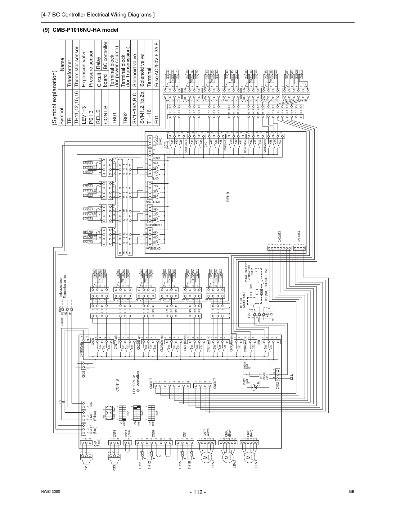
[4-7 BC Controller Electrical Wiring Diagrams ]
Hwe13080
Gb
(9) CMB-P1016NU-HA modelL1
L2
G
G
(Blue)Cnvcc1
(Yellow)Cn03
Cn02
2 2 3 2 3 1 1 1 3 2 1 (Black)Cnp1
1 2 3Tr
Cn38
1 3 CNTR(Red) 3 1Cn26
X02
X01
X30
7 5 3 1 CN27(Red) 1 3 5 7X31
X03
X04
CN28(Blue)X06
X05
X32
1 3 5 7 CN29(Green)X08
X07
X33
5 3 1 7 CN30(Black)X10
1 3 5 7X34
X09
CN31(Yellow)X12
1 3X11
X35
5 7 CN36(Green)X21
1 3 CN46(Yellow)X60
1 3Cn47
X62
X61
1 3 6 5 5 3 1Cn12
Znr02
Znr01
F01
250Vac
6.3A F
Cnout3
2 3 4 1 8 7 6 5 4 3 2 1Cnout1
1 10Sw2
Sw1
1 8Off
On
8 1Sw4
Off
On
Sw5
8 1Sw6
Off
On
8 7 6 54 Cn10
3 2Cn13
(Red) 2Cnp3
3 2 1 1 1 3 2 1Ps3
Ps1
Th11
Th12
Cn11
4 3 2 1Th15
Th16
4 5 6 3 2 1 (Yellow)Cn07
Cn05
(Red) 4 5 6 3 2 1 4 5 6 3 2 1 (Blue)Cn06
Indoor/outdoor Transmission lineTb02
S(Shield)
16 15 14 7 6 5 4 2 3 13 12 11 10 9 8 4 2 3 16 15 14 13 12 11 10 9 8 7 6 5 1 1 1 2 1 2 3 3~208V-230V
Power Supply
60HzBreaker(16A)
Fuse(16A)
Pull Box
Indoor Unit
To Next
1 2 3 4 4 3 2 1 1 2 3 4 4 3 2 1 1 2 3 4 4 3 2 1 1 2 3 4 4 3 2 1 4 3 2 1 1 2 3 4 1 2 3 4 4 3 2 1Cnout4
Cnout2
4 1 2 3 4 5 6 7 8 3 2 1 4 3 2 1 1 2 3 4 4 3 2 1 1 2 3 4 4 3 2 1 1 2 3 4 1 2 3 4 4 3 2 1 13 14 15 10 11 12 9 7 8 6 8 7 6 12 11 10 9 15 14 13 16 16 5 4 4 5 CN35(Blue)X20
X19
X39
7 5 3 1 CN34(Black)X18
X17
X38
7 5 3 1 CN33(Red)X16
X15
X37
7 5 3 1Cn39
Cn32
1 3 5 7X36
X13
X14
Cnvcc2
3 2 1 3 (Blue) 1 (Yellow)Cn40
X41
X40
X42
1 3 5 7 CN41(Green)X44
X43
X45
Cn42
X47
X46
X48
CN43(Red)X50
X49
X51
CN44(Yellow)X53
X52
3 5 1 7 5 3 1 7 5 3 1 3 5 7 6 5 4 2 3 2 3 6 5 4 7 12 11 10 9 8 11 12 10 7 9 8 1 1 2 3 4 1 2X54
CN45(Green)X56
X55
X57
7 5 3 1 7 15 14 13 1 2 4 3 16 14 15 13 5 6 8 7 16 5 4 3 2 1 1 2 3 4 5 8 5 6 7 1 2 4 3 4 3 2 1 1 2 3 4 4 3 2 1 1 2 3 4 2 3 1 2 1 3 4 4 1 2 3 4 4 3 1 1 2 3 4 4 3 2 2 3 4 Fuse AC250V 6.3A FF01
SVM1,2,1b,2b Solenoid valve Solenoid valveSv1~16A,B,C
Tb02
Terminal block (for Transmission) Terminal block (for power source)Tb01
Cont.B
Rel.B
Tr
Th11,12,15,16
Lev1~3
Ps1,3
Symbol Name (Symbol explanation) Transformer Thermister sensor Expansion valve Pressure sensor Circuit board Relay BC controller 6 6Cont.B
Rel.B
M2
M1
Sv1B
Sv1A
Sv1C
Sv2C
Sv2A
Sv2B
Sv3C
Sv3A
Sv3B
Sv4C
Sv4A
Sv4B
Sv5C
Sv5A
Sv5B
Sv6C
Sv6A
Sv6B
Sv10C
Sv10A
Sv10B
Sv9C
Sv9A
Sv9B
Sv8C
Sv8A
Sv8B
Sv7C
Sv7A
Sv7B
Sv11C
Sv11A
Sv11B
Sv12C
Sv12A
Sv12B
Sv13C
Sv13A
Sv13B
Sv14C
Sv14A
Sv14B
Sv15C
Sv15A
Sv15B
Sv16C
Sv16A
Sv16B
SVM2bSvm2
Svm1
SVM1bTb01
T1
T2
T3
T4
T5
T6
T7
T8
T9
T10
T11
T12
T13
T14
T15
T16
T1~16
TerminalM
Lev1
Lev2
M
Lev3
M
LD1:CPU in operationU
U
Dsa
1 1 3 5 7 3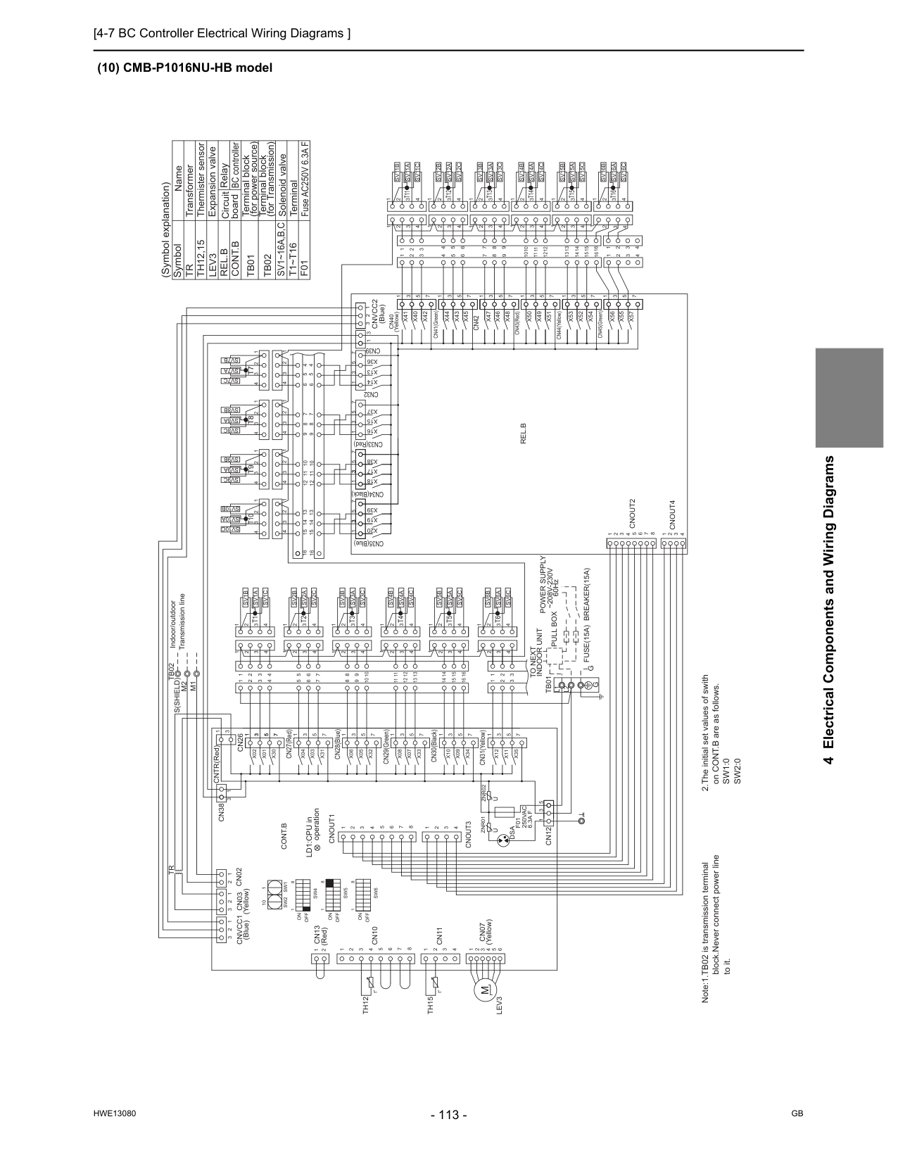
[4-7 BC Controller Electrical Wiring Diagrams ]
Hwe13080
Gb
4 Electrical Components and Wiring Diagrams (10) CMB-P1016NU-HB modelL2
L1
G
G
Note:1.TB02 is transmission terminal block.Never connect power line to it. 2.The initial set values of swith on CONT.B are as follows.Sw1:0
Sw2:0
Tb01
Sv16B
Sv16A
Sv16C
Sv15B
Sv15A
Sv15C
Sv14B
Sv14A
Sv14C
Sv13B
Sv13A
Sv13C
Sv12B
Sv12A
Sv12C
Sv11B
Sv11A
Sv11C
Sv7B
Sv7A
Sv7C
Sv8B
Sv8A
Sv8C
Sv9B
Sv9A
Sv9C
Sv10B
Sv10A
Sv10C
Sv6B
Sv6A
Sv6C
Sv5B
Sv5A
Sv5C
Sv4B
Sv4A
Sv4C
Sv3B
Sv3A
Sv3C
Sv2B
Sv2A
Sv2C
Sv1C
Sv1A
Sv1B
M1
M2
Rel.B
Cont.B
4 3 2 1 2 3 4 4 3 2 1 1 3 4 4 3 2 1 4 4 3 1 2 1 3 2 4 3 2 1 1 2 3 4 4 3 2 1 1 2 3 4 3 4 2 1 16 13 15 14 16 3 4 2 1 13 14 15 7 1 3 5 7X57
X55
X56
CN45(Green)X54
2 1 4 3 2 1 1 1 8 9 7 10 12 11 8 9 10 11 12 7 4 5 6 3 2 3 2 4 5 6 7 5 3 1 3 5 7 1 3 5 7 1 5 3X52
X53
CN44(Yellow)X51
X49
X50
CN43(Red)X48
X46
X47
Cn42
X45
X43
X44
CN41(Green) 7 5 3 1X42
X40
X41
Cn40
(Yellow) 1 (Blue) 3 1 2 3Cnvcc2
X14
X13
X36
7 5 3 1Cn32
Cn39
1 3 5 7X37
X15
X16
CN33(Red) 1 3 5 7X38
X17
X18
CN34(Black) 1 3 5 7X39
X19
X20
CN35(Blue) 5 4 4 5 16 16 13 14 15 9 10 11 12 6 7 8 6 8 7 9 12 11 10 15 14 13 1 2 3 4 4 3 2 1 4 3 2 1 1 2 3 4 4 3 2 1 1 2 3 4 4 3 2 1 1 2 3 4 1 2 3 8 7 6 5 4 3 2 1 4Cnout2
Cnout4
1 2 3 4 4 3 2 1 4 3 2 1 1 2 3 4 1 2 3 4 4 3 2 1 1 2 3 4 4 3 2 1 1 2 3 4 4 3 2 1 1 2 3 4 4 3 2 1To Next
Indoor Unit
Pull Box
Fuse(15A) Breaker(15A)
Power Supply
~208V-230V
3 3 2 1 2 1 1 1 5 6 7 8 9 10 11 12 13 14 15 16 3 2 4 8 9 10 11 12 13 3 2 4 5 6 7 14 15 16S(Shield)Tb02
Indoor/outdoor Transmission lineCn07
(Yellow) 1 2 3 6 5 4Th15
1 2 3 4Cn11
Th12
1 1 2 (Red)Cn13
2 3Cn10
4 5 6 7 8Sw6
1 8Sw5
Sw4
1 8On
Off
On
Off
On
Off
8 1Sw1
Sw2
10 1Cnout1
1 2 3 4 5 6 7 8 1 4 3 2Cnout3
F01
250Vac
6.3A F
Znr01
Znr02
Cn12
1 3 5 7 5X35
X11
3 1X12
CN31(Yellow)X09
X34
7 5 3 1X10
CN30(Black) 7 1 3 5X33
X07
X08
CN29(Green) 7 5 3 1X32
X05
X06
CN28(Blue)X04
X03
X31
7 5 3 1 CN27(Red) 1 3 5 7X30
X01
X02
Cn26
1 3 CNTR(Red) 3 1Cn38
Tr
1 1 1 3 2 3 2 2Cn02
Cn03
(Yellow)Cnvcc1
(Blue) TerminalT1~T16
Solenoid valveSv1~16A,B,C
Tb02
Terminal block (for Transmission) Terminal block (for power source)Tb01
Cont.B
Rel.B
Tr
Th12,15
Lev3
Symbol Name Transformer Thermister sensor Expansion valve Circuit board Relay BC controller (Symbol explanation)T1
T2
T3
T4
T5
T6
T11
T12
T13
T14
T15
T16
T10
T9
T8
T7
Fuse AC250V 6.3A FF01
t° t°Dsa
U
U
LD1:CPU in operationM
Lev3
3 3 7 5 3 1 1
[4-7 BC Controller Electrical Wiring Diagrams ]
Hwe13080
Gb
Hwe13080
Gb
Chapter 5 Control 5-1 Dipswitch Functions and Factory Settings .................................................................................... 117 5-1-1 Outdoor Unit Switch Functions and Factory Settings ......................................................................... 117 5-1-2 Indoor Unit Switch Functions and Factory Settings ............................................................................ 121 5-1-3 Remote Controller Switch Functions and Factory Settings................................................................. 122 5-1-4 BC Controller Switch Settings............................................................................................................. 123 5-2 Outdoor Unit Control........................................................................................................................ 124 5-2-1 Overview............................................................................................................................................. 124 5-2-2 Rotation Control.................................................................................................................................. 124 5-2-3 Initial Control....................................................................................................................................... 124 5-2-4 Startup Control.................................................................................................................................... 124 5-2-5 Refrigerant Bypass Control................................................................................................................. 125 5-2-6 Frequency Control .............................................................................................................................. 126 5-2-7 Defrost Operation Control................................................................................................................... 127 5-2-8 ON-defrost operation control............................................................................................................... 129 5-2-9 Refrigerant Recovery Control ............................................................................................................. 129 5-2-10 Oil recovery during compressor operation at low frequency............................................................... 130 5-2-11 Outdoor Unit Fan Control.................................................................................................................... 130 5-2-12 Compressor discharge superheat control (expansion valve
Hwe13080
Gb
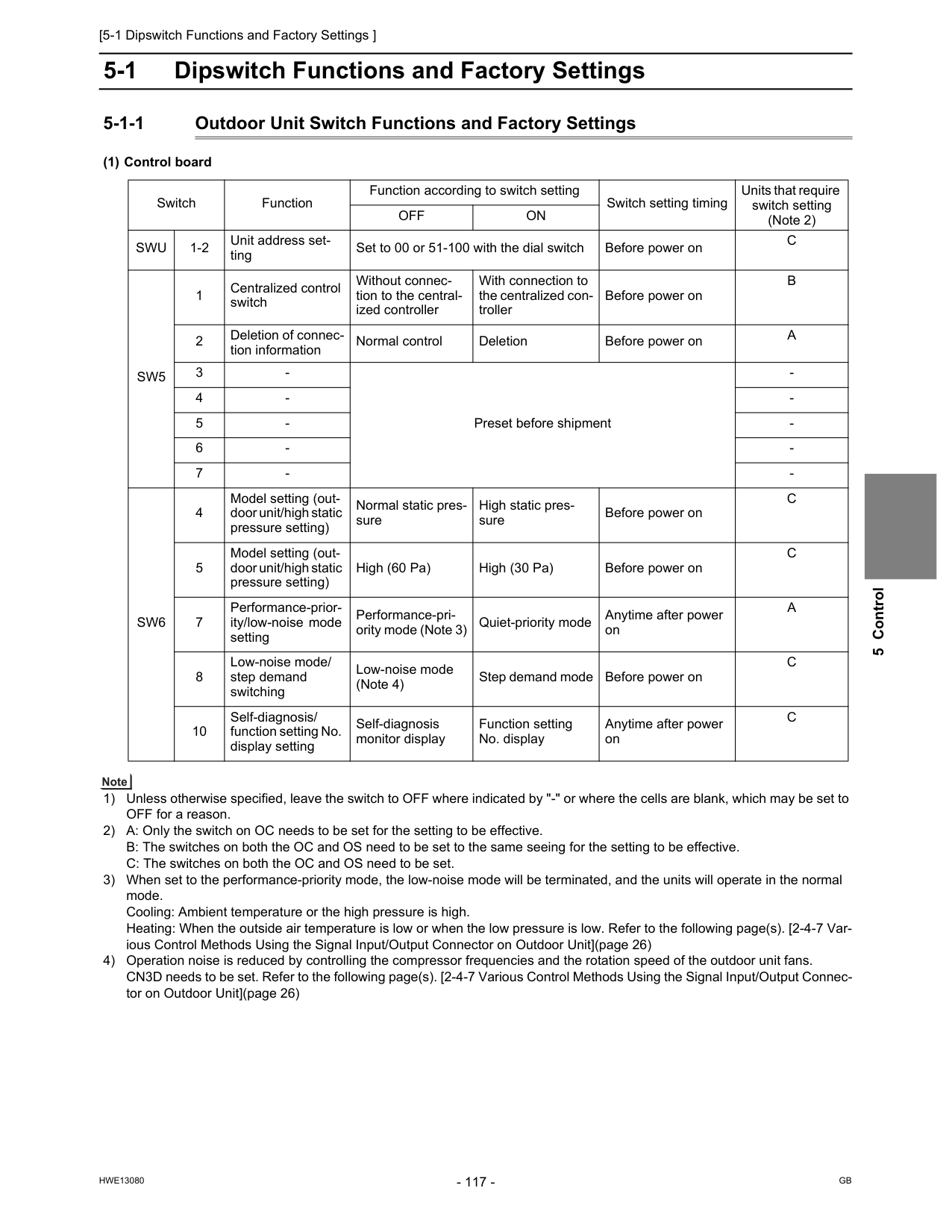
[5-1 Dipswitch Functions and Factory Settings ]
Hwe13080
Gb
5 Control 5 Control5-1 Dipswitch Functions and Factory Settings 5-1-1 Outdoor Unit Switch Functions and Factory Settings (1) Control board 1) Unless otherwise specified, leave the switch to OFF where indicated by "-" or where the cells are blank, which may be set to OFF for a reason. 2) A: Only the switch on OC needs to be set for the setting to be effective. B: The switches on both the OC and OS need to be set to the same seeing for the setting to be effective. C: The switches on both the OC and OS need to be set. 3) When set to the performance-priority mode, the low-noise mode will be terminated, and the units will operate in the normal mode. Cooling: Ambient temperature or the high pressure is high. Heating: When the outside air temperature is low or when the low pressure is low. Refer to the following page(s). [2-4-7 Var- ious Control Methods Using the Signal Input/Output Connector on Outdoor Unit](page 26) 4) Operation noise is reduced by controlling the compressor frequencies and the rotation speed of the outdoor unit fans. CN3D needs to be set. Refer to the following page(s). [2-4-7 Various Control Methods Using the Signal Input/Output Connec- tor on Outdoor Unit](page 26) Switch Function Function according to switch setting Switch setting timing Units that require switch setting (Note 2)Off
On
Swu
1-2 Unit address set- ting Set to 00 or 51-100 with the dial switch Before power onC
Sw5
1 Centralized control switch Without connec- tion to the central- ized controller With connection to the centralized con- troller Before power onB
2 Deletion of connec- tion information Normal control Deletion Before power onA
3Sw6
4 Model setting (out- door unit/high static pressure setting) Normal static pres- sure High static pres- sure Before power onC
5 Model setting (out- door unit/high static pressure setting) High (60 Pa) High (30 Pa) Before power onC
7 Performance-prior- ity/low-noise mode setting Performance-pri- ority mode (Note 3) Quiet-priority mode Anytime after power onA
8 Low-noise mode/ step demand switching Low-noise mode (Note 4) Step demand mode Before power onC
10 Self-diagnosis/ function setting No. display setting Self-diagnosis monitor display Function setting No. display Anytime after power onC
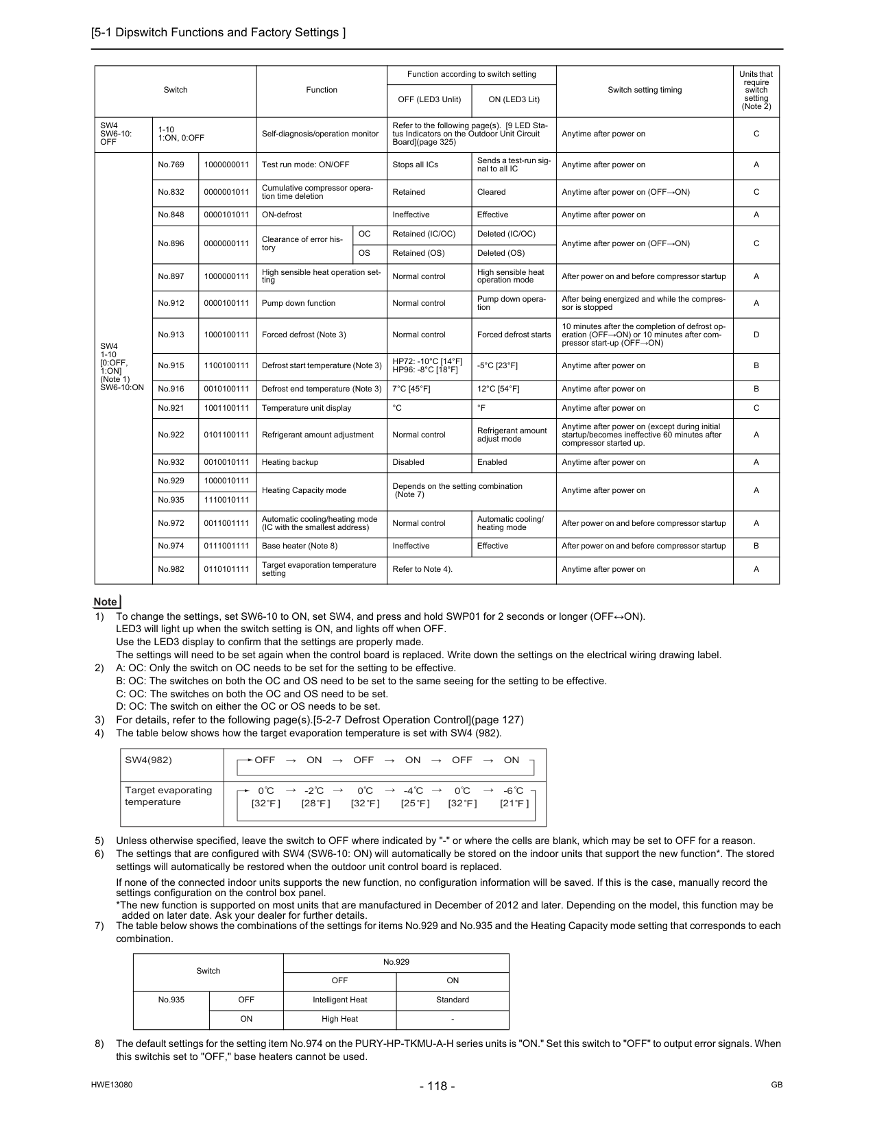
[5-1 Dipswitch Functions and Factory Settings ]
Hwe13080
Gb
1) To change the settings, set SW6-10 to ON, set SW4, and press and hold SWP01 for 2 seconds or longer (OFF↔ON). LED3 will light up when the switch setting is ON, and lights off when OFF. Use the LED3 display to confirm that the settings are properly made. The settings will need to be set again when the control board is replaced. Write down the settings on the electrical wiring drawing label. 2) A: OC: Only the switch on OC needs to be set for the setting to be effective. B: OC: The switches on both the OC and OS need to be set to the same seeing for the setting to be effective. C: OC: The switches on both the OC and OS need to be set. D: OC: The switch on either the OC or OS needs to be set. 3) For details, refer to the following page(s).[5-2-7 Defrost Operation Control](page 127) 4) The table below shows how the target evaporation temperature is set with SW4 (982). 5) Unless otherwise specified, leave the switch to OFF where indicated by "-" or where the cells are blank, which may be set to OFF for a reason. 6) The settings that are configured with SW4 (SW6-10: ON) will automatically be stored on the indoor units that support the new function*. The stored settings will automatically be restored when the outdoor unit control board is replaced. If none of the connected indoor units supports the new function, no configuration information will be saved. If this is the case, manually record the settings configuration on the control box panel. *The new function is supported on most units that are manufactured in December of 2012 and later. Depending on the model, this function may be added on later date. Ask your dealer for further details. 7) The table below shows the combinations of the settings for items No.929 and No.935 and the Heating Capacity mode setting that corresponds to each combination. 8) The default settings for the setting item No.974 on the PURY-HP-TKMU-A-H series units is "ON." Set this switch to "OFF" to output error signals. When this switchis set to "OFF," base heaters cannot be used. Switch Function Function according to switch setting Switch setting timing Units that require switch setting (Note 2) OFF (LED3 Unlit) ON (LED3 Lit)Sw4
Sw6-10:
Off
1-101:On, 0:Off
Self-diagnosis/operation monitor Refer to the following page(s). [9 LED Sta- tus Indicators on the Outdoor Unit Circuit Board](page 325) Anytime after power onC
Sw4
1-10[0:Off,
1:On]
(Note 1)Sw6-10:On
No.769 1000000011 Test run mode: ON/OFF Stops all ICs Sends a test-run sig- nal to all IC Anytime after power onA
No.832 0000001011 Cumulative compressor opera- tion time deletion Retained Cleared Anytime after power on (OFF→ON)C
No.848 0000101011 ON-defrost Ineffective Effective Anytime after power onA
No.896 0000000111 Clearance of error his- toryOc
Retained (IC/OC) Deleted (IC/OC) Anytime after power on (OFF→ON)C
Os
Retained (OS) Deleted (OS) No.897 1000000111 High sensible heat operation set- ting Normal control High sensible heat operation mode After power on and before compressor startupA
No.912 0000100111 Pump down function Normal control Pump down opera- tion After being energized and while the compres- sor is stoppedA
No.913 1000100111 Forced defrost (Note 3) Normal control Forced defrost starts 10 minutes after the completion of defrost op- eration (OFF→ON) or 10 minutes after com- pressor start-up (OFF→ON)D
No.915 1100100111 Defrost start temperature (Note 3)Hp72: -10°C [14°F]
Hp96: -8°C [18°F]
-5°C [23°F]
Anytime after power onB
No.916 0010100111 Defrost end temperature (Note 3)7°C [45°F]
12°C [54°F]
Anytime after power onB
No.921 1001100111 Temperature unit display°C
°F
Anytime after power onC
No.922 0101100111 Refrigerant amount adjustment Normal control Refrigerant amount adjust mode Anytime after power on (except during initial startup/becomes ineffective 60 minutes after compressor started up.A
No.932 0010010111 Heating backup Disabled Enabled Anytime after power onA
No.929 1000010111 Heating Capacity mode Depends on the setting combination (Note 7) Anytime after power onA
No.935 1110010111 No.972 0011001111 Automatic cooling/heating mode (IC with the smallest address) Normal control Automatic cooling/ heating mode After power on and before compressor startupA
No.974 0111001111 Base heater (Note 8) Ineffective Effective After power on and before compressor startupB
No.982 0110101111 Target evaporation temperature setting Refer to Note 4). Anytime after power onA
Switch No.929Off
On
No.935Off
Intelligent Heat StandardOn
High HeatSw4(982)
Off → On → Off → On → Off → On
Target evaporating temperature 0 [32 ] [32 ] [32 ] [25 ] -2 [28 ] 0 0 -4 [21 ] -6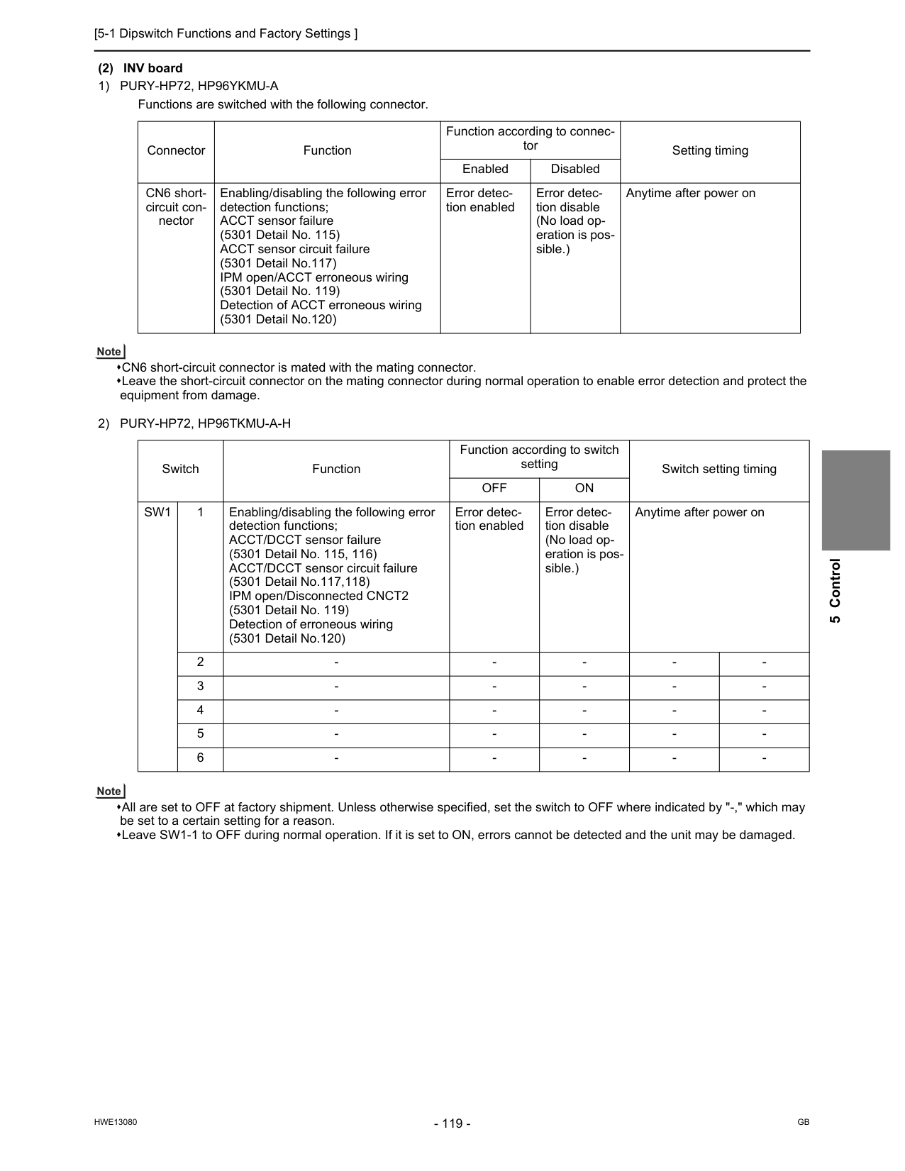
[5-1 Dipswitch Functions and Factory Settings ]
Hwe13080
Gb
5 Control (2) INV board1) Pury-Hp72, Hp96Ykmu-A
Functions are switched with the following connector. CN6 short-circuit connector is mated with the mating connector. Leave the short-circuit connector on the mating connector during normal operation to enable error detection and protect the equipment from damage.2) Pury-Hp72, Hp96Tkmu-A-H
All are set to OFF at factory shipment. Unless otherwise specified, set the switch to OFF where indicated by "-," which may be set to a certain setting for a reason. Leave SW1-1 to OFF during normal operation. If it is set to ON, errors cannot be detected and the unit may be damaged. Connector Function Function according to connec- tor Setting timing Enabled Disabled CN6 short- circuit con- nector Enabling/disabling the following error detection functions; ACCT sensor failure (5301 Detail No. 115) ACCT sensor circuit failure (5301 Detail No.117) IPM open/ACCT erroneous wiring (5301 Detail No. 119) Detection of ACCT erroneous wiring (5301 Detail No.120) Error detec- tion enabled Error detec- tion disable (No load op- eration is pos- sible.) Anytime after power on Switch Function Function according to switch setting Switch setting timingOff
On
Sw1
1 Enabling/disabling the following error detection functions; ACCT/DCCT sensor failure (5301 Detail No. 115, 116) ACCT/DCCT sensor circuit failure (5301 Detail No.117,118) IPM open/Disconnected CNCT2 (5301 Detail No. 119) Detection of erroneous wiring (5301 Detail No.120) Error detec- tion enabled Error detec- tion disable (No load op- eration is pos- sible.) Anytime after power on 2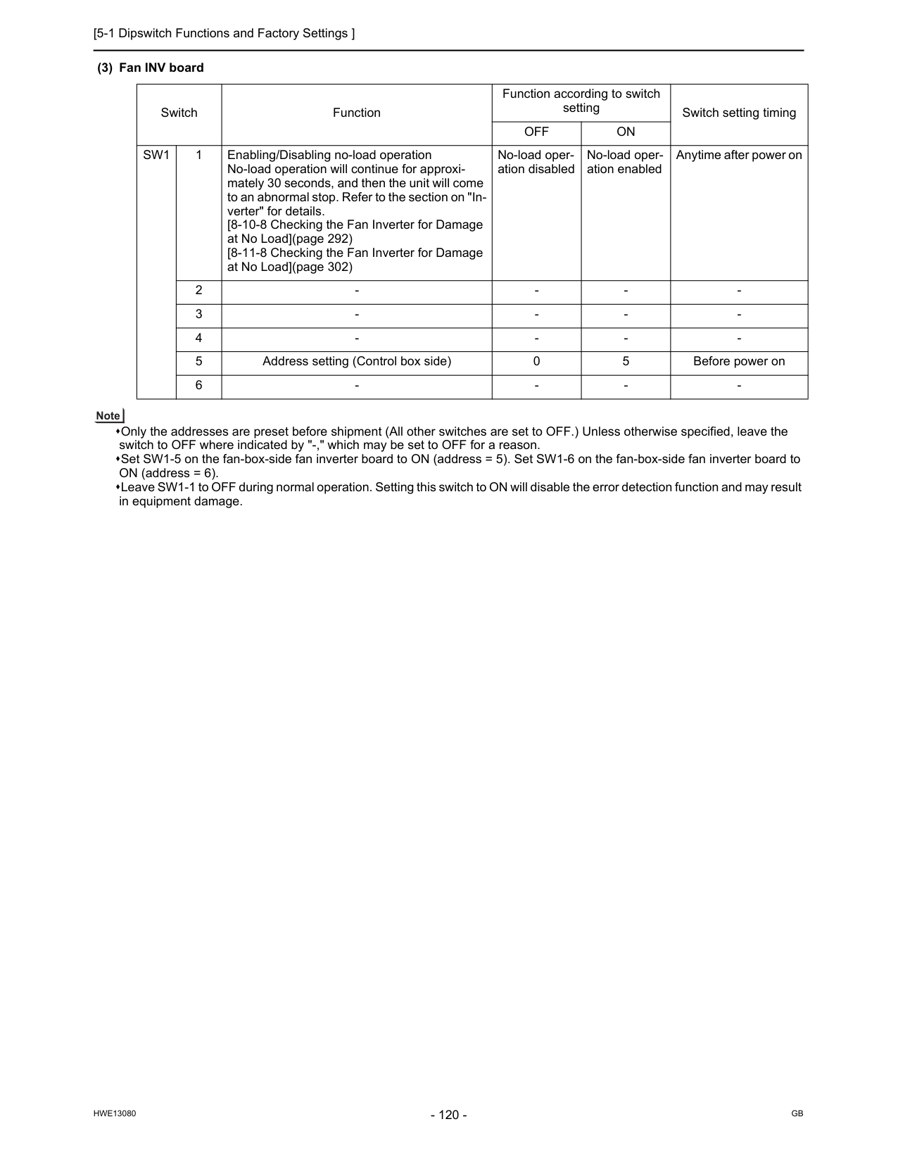
[5-1 Dipswitch Functions and Factory Settings ]
Hwe13080
Gb
(3) Fan INV board Only the addresses are preset before shipment (All other switches are set to OFF.) Unless otherwise specified, leave the switch to OFF where indicated by "-," which may be set to OFF for a reason. Set SW1-5 on the fan-box-side fan inverter board to ON (address = 5). Set SW1-6 on the fan-box-side fan inverter board to ON (address = 6). Leave SW1-1 to OFF during normal operation. Setting this switch to ON will disable the error detection function and may result in equipment damage. Switch Function Function according to switch setting Switch setting timingOff
On
Sw1
1 Enabling/Disabling no-load operation No-load operation will continue for approxi- mately 30 seconds, and then the unit will come to an abnormal stop. Refer to the section on "In- verter" for details. [8-10-8 Checking the Fan Inverter for Damage at No Load](page 292) [8-11-8 Checking the Fan Inverter for Damage at No Load](page 302) No-load oper- ation disabled No-load oper- ation enabled Anytime after power on 2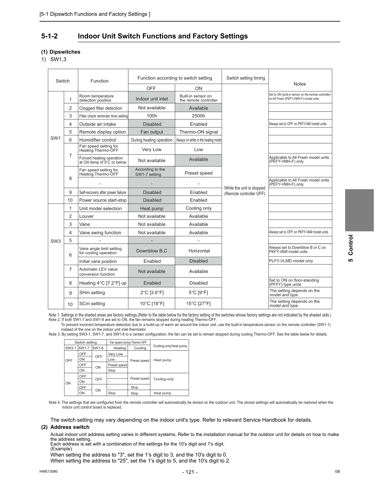
[5-1 Dipswitch Functions and Factory Settings ]
Hwe13080
Gb
5 Control 5-1-2 Indoor Unit Switch Functions and Factory Settings (1) Dipswitches1) Sw1,3
The switch setting may vary depending on the indoor unit's type. Refer to relevant Service Handbook for details. (2) Address switch Actual indoor unit address setting varies in different systems. Refer to the installation manual for the outdoor unit for details on how to make the address setting. Each address is set with a combination of the settings for the 10's digit and 1's digit. (Example) When setting the address to "3", set the 1's digit to 3, and the 10's digit to 0. When setting the address to "25", set the 1's digit to 5, and the 10's digit to 2.Sw3-1
Off
Off
Off
On
On
On
Off
On
Off
On
Off
On
Off
On
Very Low Low Preset speed Preset speed Preset speed Stop Stop Stop Stop Switch settingSw1-7
Sw1-8
Heating Cooling Cooling-only/heat pump Heat pump Cooling-only Heat pump Fan speed during Thermo-OFF Note 2. If both SW1-7 and SW1-8 are set to ON, the fan remains stopped during heating Thermo-OFF. To prevent incorrect temperature detection due to a build-up of warm air around the indoor unit, use the built-in temperature sensor on the remote controller (SW1-1) instead of the one on the indoor unit inlet thermistor. Note 3. By setting SW3-1, SW1-7, and SW1-8 to a certain configuration, the fan can be set to remain stopped during cooling Thermo-OFF. See the table below for details. Note 4. The settings that are configured from the remote controller will automatically be stored on the outdoor unit. The stored settings will automatically be restored when the indoor unit control board is replaced. Switch Function Function according to switch settingOff
On
Switch setting timing NotesSw1
Sw3
1 2 3 4 5 6 7 8 9 10 9 10 1 2 3 4 5 6 7 8 Room temperature detection position Clogged filter detection Filter check reminder time setting Outside air intake Remote display option Humidifier control Self-recovery after power failure Fan speed setting for Heating Thermo-OFF Power source start-stop Unit model selection Louver Vane Vane swing function2°C [3.6°F]
10°C [18°F]
5°C [9°F]
15°C [27°F]
The setting depends on the model and type. The setting depends on the model and type. SCm setting Disabled Forced heating operation at OA temp of 5 C or below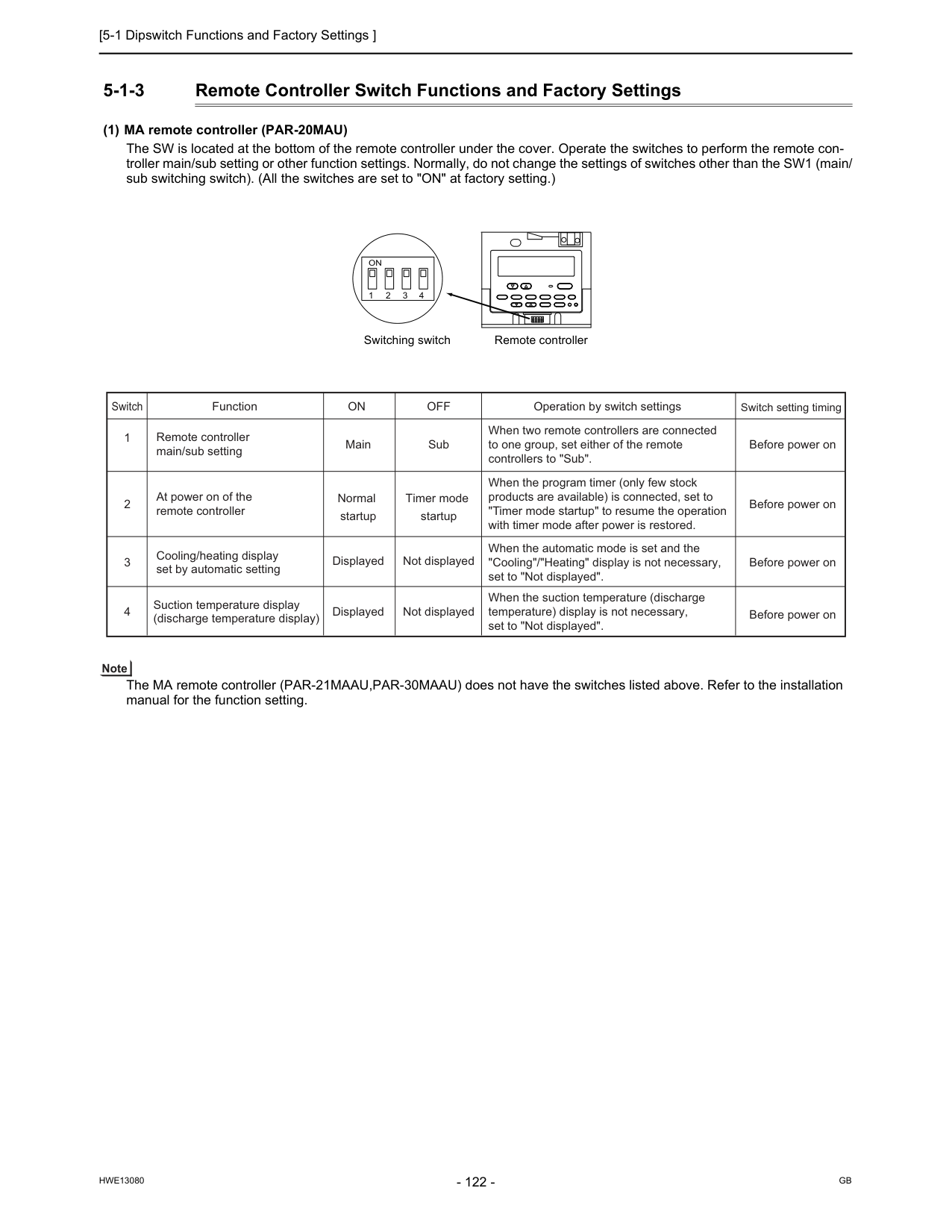
[5-1 Dipswitch Functions and Factory Settings ]
Hwe13080
Gb
5-1-3 Remote Controller Switch Functions and Factory Settings (1) MA remote controller (PAR-20MAU) The SW is located at the bottom of the remote controller under the cover. Operate the switches to perform the remote con- troller main/sub setting or other function settings. Normally, do not change the settings of switches other than the SW1 (main/ sub switching switch). (All the switches are set to "ON" at factory setting.) The MA remote controller (PAR-21MAAU,PAR-30MAAU) does not have the switches listed above. Refer to the installation manual for the function setting. Remote controller Switching switch 1On
2 3 4 Switch 2 1 Function Remote controller main/sub setting At power on of the remote controller Normal startup Timer mode startup 3 Cooling/heating display set by automatic setting Displayed Not displayed 4 Suction temperature display (discharge temperature display) Displayed Not displayed Operation by switch settings Switch setting timingOn
Off
Main Sub Before power on Before power on Before power on Before power on When two remote controllers are connected to one group, set either of the remote controllers to "Sub". When the program timer (only few stock products are available) is connected, set to "Timer mode startup" to resume the operation with timer mode after power is restored. When the automatic mode is set and the "Cooling"/"Heating" display is not necessary, set to "Not displayed". When the suction temperature (discharge temperature) display is not necessary, set to "Not displayed".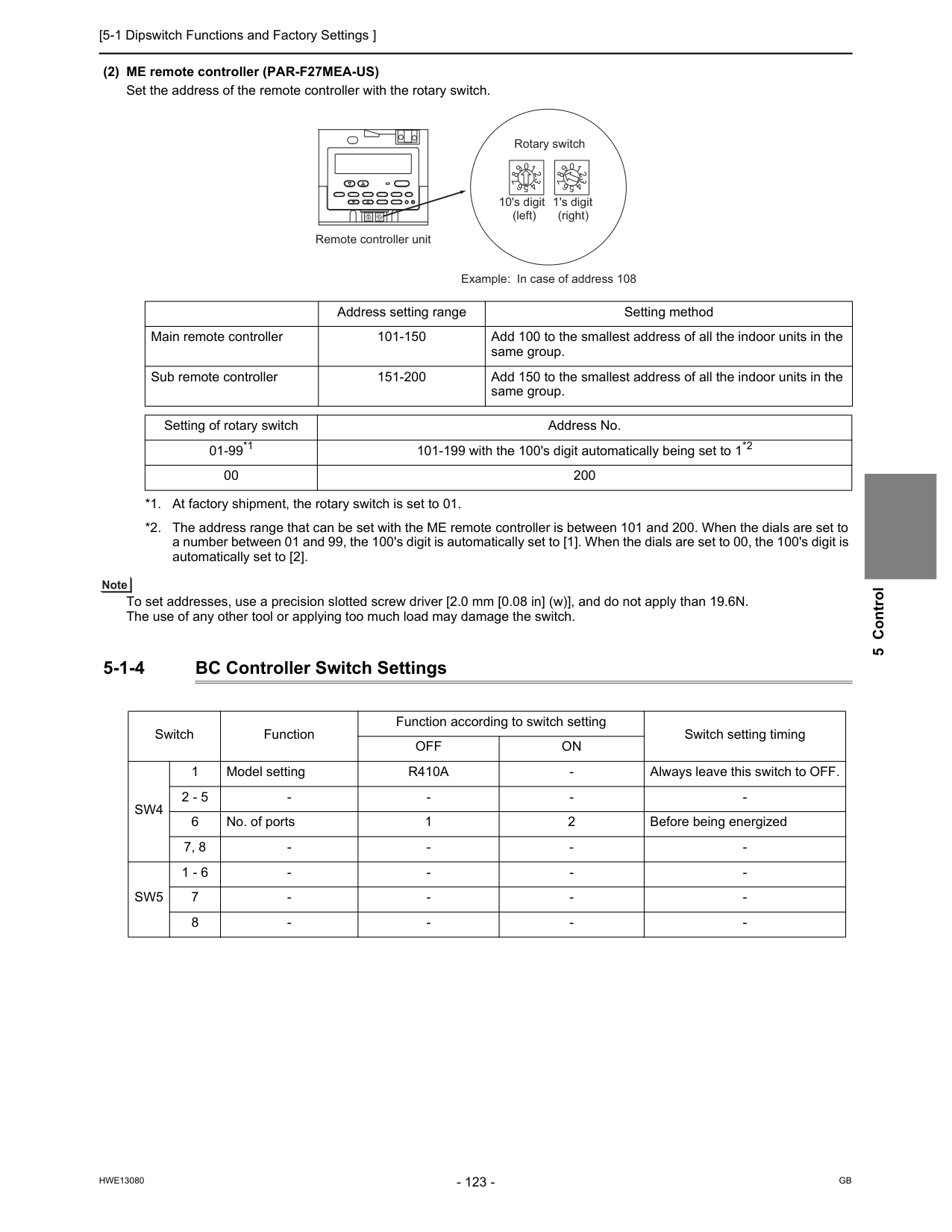
[5-1 Dipswitch Functions and Factory Settings ]
Hwe13080
Gb
5 Control (2) ME remote controller (PAR-F27MEA-US) Set the address of the remote controller with the rotary switch. To set addresses, use a precision slotted screw driver [2.0 mm [0.08 in] (w)], and do not apply than 19.6N. The use of any other tool or applying too much load may damage the switch. 5-1-4 BC Controller Switch Settings 0 1 2 3 4 5 6 7 8 9 0 1 2 3 4 5 6 7 8 9 0 1 2 3 4 5 6 7 8 9 0 1 2 3 4 5 6 7 8 9 10's digit 1's digit (left) (right) Remote controller unit Rotary switch Example: In case of address 108 Address setting range Setting method Main remote controller 101-150 Add 100 to the smallest address of all the indoor units in the same group. Sub remote controller 151-200 Add 150 to the smallest address of all the indoor units in the same group. Setting of rotary switch Address No. 01-99*1 101-199 with the 100's digit automatically being set to 1*2 00 200 *1. At factory shipment, the rotary switch is set to 01. *2. The address range that can be set with the ME remote controller is between 101 and 200. When the dials are set to a number between 01 and 99, the 100's digit is automatically set to [1]. When the dials are set to 00, the 100's digit is automatically set to [2]. Switch Function Function according to switch setting Switch setting timingOff
On
Sw4
1 Model settingR410A
Sw5
1 - 6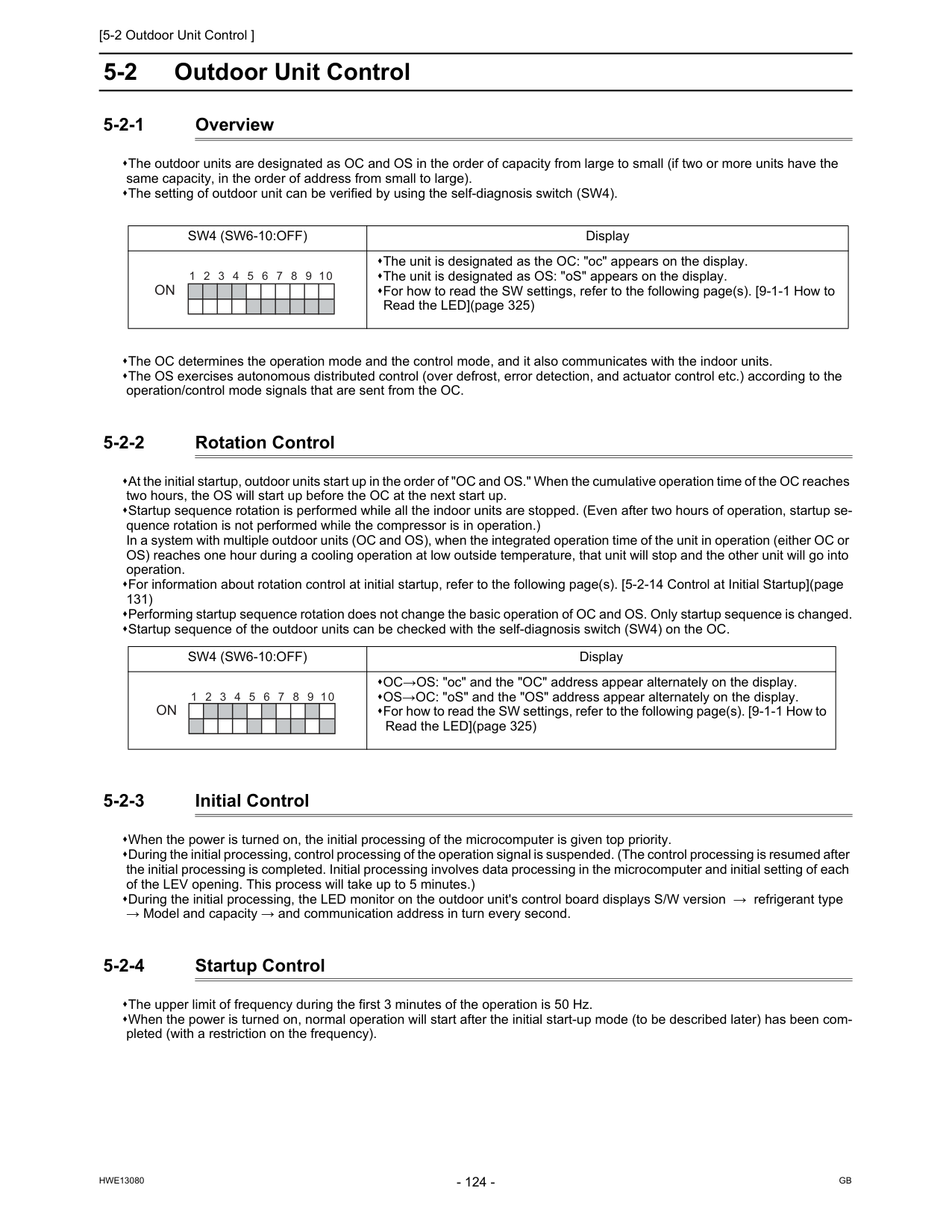
[5-2 Outdoor Unit Control ]
Hwe13080
Gb
5-2 Outdoor Unit Control 5-2-1 Overview The outdoor units are designated as OC and OS in the order of capacity from large to small (if two or more units have the same capacity, in the order of address from small to large). The setting of outdoor unit can be verified by using the self-diagnosis switch (SW4). The OC determines the operation mode and the control mode, and it also communicates with the indoor units. The OS exercises autonomous distributed control (over defrost, error detection, and actuator control etc.) according to the operation/control mode signals that are sent from the OC. 5-2-2 Rotation Control At the initial startup, outdoor units start up in the order of "OC and OS." When the cumulative operation time of the OC reaches two hours, the OS will start up before the OC at the next start up. Startup sequence rotation is performed while all the indoor units are stopped. (Even after two hours of operation, startup se- quence rotation is not performed while the compressor is in operation.) In a system with multiple outdoor units (OC and OS), when the integrated operation time of the unit in operation (either OC or OS) reaches one hour during a cooling operation at low outside temperature, that unit will stop and the other unit will go into operation. For information about rotation control at initial startup, refer to the following page(s). [5-2-14 Control at Initial Startup](page 131) Performing startup sequence rotation does not change the basic operation of OC and OS. Only startup sequence is changed. Startup sequence of the outdoor units can be checked with the self-diagnosis switch (SW4) on the OC. 5-2-3 Initial Control When the power is turned on, the initial processing of the microcomputer is given top priority. During the initial processing, control processing of the operation signal is suspended. (The control processing is resumed after the initial processing is completed. Initial processing involves data processing in the microcomputer and initial setting of each of the LEV opening. This process will take up to 5 minutes.) During the initial processing, the LED monitor on the outdoor unit's control board displays S/W version → refrigerant type → Model and capacity → and communication address in turn every second. 5-2-4 Startup Control The upper limit of frequency during the first 3 minutes of the operation is 50 Hz. When the power is turned on, normal operation will start after the initial start-up mode (to be described later) has been com- pleted (with a restriction on the frequency).Sw4 (Sw6-10:Off)
Display The unit is designated as the OC: "oc" appears on the display. The unit is designated as OS: "oS" appears on the display. For how to read the SW settings, refer to the following page(s). [9-1-1 How to Read the LED](page 325)On
1 2 3 5 4 6 7 8 9 10Sw4 (Sw6-10:Off)
Display OC→OS: "oc" and the "OC" address appear alternately on the display. OS→OC: "oS" and the "OS" address appear alternately on the display. For how to read the SW settings, refer to the following page(s). [9-1-1 How to Read the LED](page 325)On
1 2 3 5 4 6 7 8 9 10
[5-2 Outdoor Unit Control ]
Hwe13080
Gb
5 Control 5-2-5 Refrigerant Bypass Control Bypass solenoid valves, which bypass the high- and low- pressure sides, perform the following functions. (1) Bypass solenoid valve (SV1a) (ON = Open) (2) Bypass solenoid valve (SV9) (ON = Open) (3) Bypass solenoid valve (SV5b) (ON = Closed) Operation SV1aOn
Off
When starting-up the compressor of each outdoor unit ON for 4 minutes. After the restoration of thermo or 3 minutes after restart ON for 4 minutes. During cooling or heating operation with the compressor stopped Always ON. Exception: OFF when 63HS1-63LS is 0.2MPa[29psi] or less After the operation has stopped ON for 3 minutes. Exception: OFF when 63HS1-63LS is 0.2MPa[29psi] or less During defrost operationOn
While the compressor is operating at the minimum frequency and when the low pres- sure (63LS) drops (3 or more minutes after compressor startup) When low pressure (63LS) drops below 0.23MPa[33psi]. When low pressure (63LS) ex- ceeds 0.38MPa[55psi]. When high pressure (63HS1) rises When 63HS1 exceeds 3.62MPa[525psi] When 63HS1 is or below 3.43MPa[497psi] and 30 seconds have passed OperationSv9
On
Off
When high pressure (63HS1) rises during the heating operation When 63HS1 exceeds 3.50MPa [507psi] When SV5b is ON and the pressure is 2.70MPa[391psi]or below Others Always OFF Operation SV5b ON (Closed) OFF (Open) When high pressure (63HS1) rises during the heating operation When the pressure is 2.70MPa [391psi] or below When SV9 is ON and the pressure is 3.50MPa [507psi] or more At startup ON (Closed) During defrost cycle ON (Closed) When returning to normal operation after completion of the defrost cycle OFF (Open) for 3 minutes and goes ON (Closed) Others Always ON (Closed)
[5-2 Outdoor Unit Control ]
Hwe13080
Gb
5-2-6 Frequency Control Depending on the capacity required, the frequency of the compressor is controlled to keep constant evaporation temperature (0°C [32°F] = 0.71 MPa [103 psi]) during cooling operation, and condensing temperature (49°C [120°F] = 2.88 MPa [418 psi]) during heating operation. The table below summarizes the operating frequency ranges of the inverter compressor during normal operation. The OS in the multiple-outdoor-unit system operates at the actual compressor frequency value that is calculated by the OS based on the preliminary compressor frequency value that the OC determines. The maximum frequency during heating operation depends on the outside air temperature and the dipswitch settings. (1) Pressure limit The upper limit of high pressure (63HS1) is preset, and when it exceeds the upper limit, the frequency is decreased every 15 seconds. The actuation pressure is when the high-pressure reading on 63HS1 is 3.58MPa[519psi]. (2) Discharge temperature limit Discharge temperature (TH4) of the compressor in operation is monitored, and when it exceeds the upper limit, the frequency is decreased every minute. Operating temperature is 115°C [239°F]. (3) Periodic frequency control Frequency control other than the ones performed at start-up, upon status change, and for protection is called periodic frequen- cy control (convergent control) and is performed in the following manner. Periodic control cycle Periodic control is performed after the following time has passed 30 seconds after either compressor start-up or the completion of defrost operation 30 seconds after frequency control based on discharge temperature or pressure limit The amount of frequency change The amount of frequency change is controlled to approximate the target value based on the evaporation temperature (Te) and condensing temperature (Tc). Model Frequency/cooling Frequency/heating Max Min Max MinHp72
50Hz 15Hz 103Hz 29HzHp96
64Hz 15Hz 120Hz 29Hz
[5-2 Outdoor Unit Control ]
Hwe13080
Gb
5 Control 5-2-7 Defrost Operation Control (1) Starting the defrost operation The defrost cycle will start when all of the three conditions (outside temperature, cumulative compressor operation time, and pipe temperature) under(Th7)
-5ºC [23ºF] or above -5ºC [23ºF] or below Cumulative compressor operation time 50 minutes or more 90 minutes or more if the defrost prohibit timer is set to 90. 250 minutes or more Pipe temperature(Th6)
The pipe tempera- ture has stayed be- low the temperatures in the table below (Note1) for three minutes. The pipe temperature has stayed below the value obtained from the formula "Outside temperature (TH7) - 5ºC [23ºF] " for three minutes, or the 63LS reading has stayed below the value obtained from the formula "1.5 + 0.02 × (20+TH7ºC) (kgf/cm2) [21.3+0.158×(4+TH7ºF) (lb/in2) ] " for three minutes. The pipe temperature has stayed below the temperatures in the table below (Note1) for three minutesHp72
Hp96
Sw4 (915) Off
-10ºC [14ºF] -8ºC [18ºF]Sw4 (915) On
-5ºC [23ºF] -5ºC [23ºF]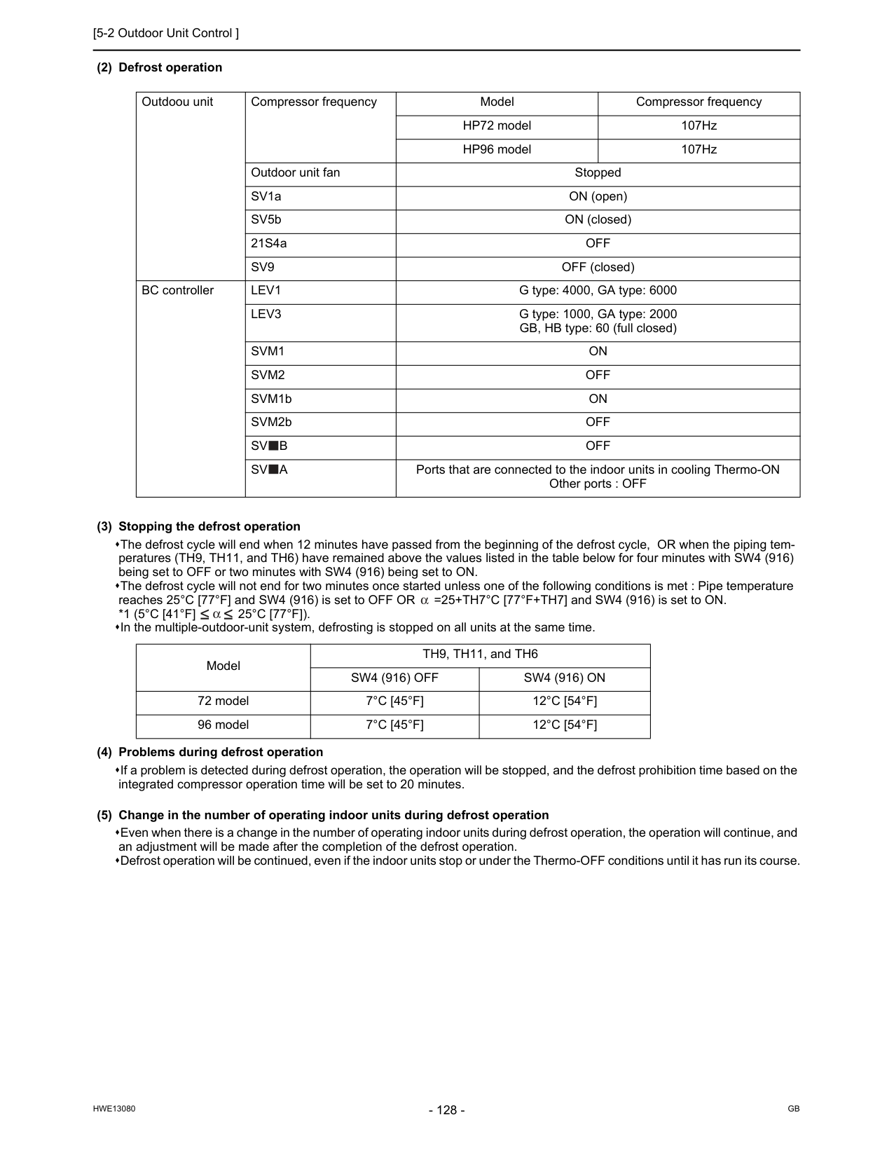
[5-2 Outdoor Unit Control ]
Hwe13080
Gb
(2) Defrost operation (3) Stopping the defrost operation The defrost cycle will end when 12 minutes have passed from the beginning of the defrost cycle, OR when the piping tem- peratures (TH9, TH11, and TH6) have remained above the values listed in the table below for four minutes with SW4 (916) being set to OFF or two minutes with SW4 (916) being set to ON. The defrost cycle will not end for two minutes once started unless one of the following conditions is met : Pipe temperature reaches 25°C [77°F] and SW4 (916) is set to OFF OR =25+TH7°C [77°F+TH7] and SW4 (916) is set to ON.*1 (5°C [41°F]
25°C [77°F]).
In the multiple-outdoor-unit system, defrosting is stopped on all units at the same time. (4) Problems during defrost operation If a problem is detected during defrost operation, the operation will be stopped, and the defrost prohibition time based on the integrated compressor operation time will be set to 20 minutes. (5) Change in the number of operating indoor units during defrost operation Even when there is a change in the number of operating indoor units during defrost operation, the operation will continue, and an adjustment will be made after the completion of the defrost operation. Defrost operation will be continued, even if the indoor units stop or under the Thermo-OFF conditions until it has run its course. Outdoou unit Compressor frequency Model Compressor frequency HP72 model 107Hz HP96 model 107Hz Outdoor unit fan Stopped SV1a ON (open) SV5b ON (closed) 21S4aOff
Sv9
OFF (closed) BC controllerLev1
G type: 4000, GA type: 6000Lev3
G type: 1000, GA type: 2000 GB, HB type: 60 (full closed)Svm1
On
Svm2
Off
SVM1bOn
SVM2bOff
Sv
B
Off
Sv
A
Ports that are connected to the indoor units in cooling Thermo-ON Other ports : OFF Model TH9, TH11, and TH6Sw4 (916) Off
Sw4 (916) On
72 model7°C [45°F]
12°C [54°F]
96 model7°C [45°F]
12°C [54°F]
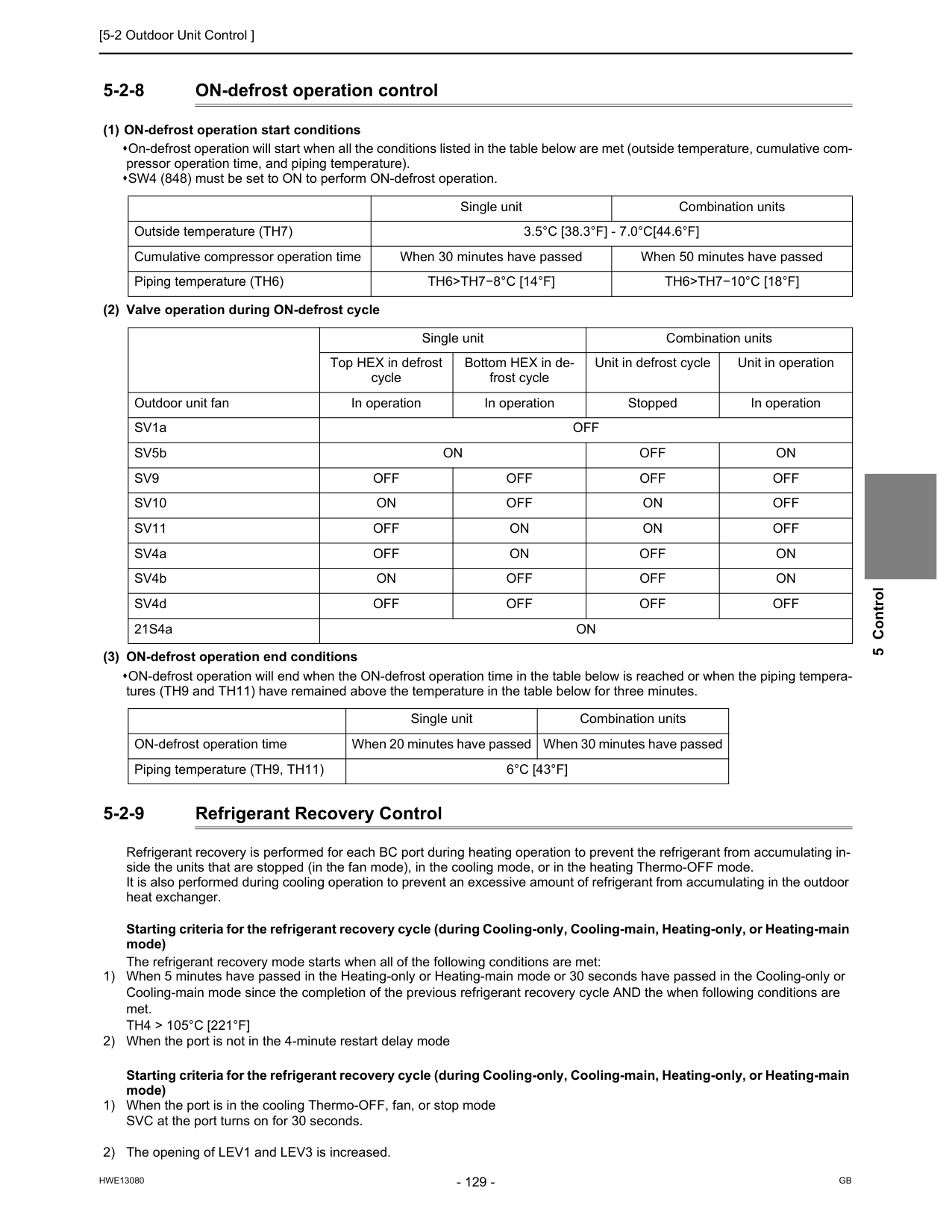
[5-2 Outdoor Unit Control ]
Hwe13080
Gb
5 Control 5-2-8 ON-defrost operation control (1) ON-defrost operation start conditions On-defrost operation will start when all the conditions listed in the table below are met (outside temperature, cumulative com- pressor operation time, and piping temperature). SW4 (848) must be set to ON to perform ON-defrost operation. (2) Valve operation during ON-defrost cycle (3) ON-defrost operation end conditions ON-defrost operation will end when the ON-defrost operation time in the table below is reached or when the piping tempera- tures (TH9 and TH11) have remained above the temperature in the table below for three minutes. 5-2-9 Refrigerant Recovery Control Refrigerant recovery is performed for each BC port during heating operation to prevent the refrigerant from accumulating in- side the units that are stopped (in the fan mode), in the cooling mode, or in the heating Thermo-OFF mode. It is also performed during cooling operation to prevent an excessive amount of refrigerant from accumulating in the outdoor heat exchanger. Starting criteria for the refrigerant recovery cycle (during Cooling-only, Cooling-main, Heating-only, or Heating-main mode) The refrigerant recovery mode starts when all of the following conditions are met: 1) When 5 minutes have passed in the Heating-only or Heating-main mode or 30 seconds have passed in the Cooling-only or Cooling-main mode since the completion of the previous refrigerant recovery cycle AND the when following conditions are met.Th4 > 105°C [221°F]
2) When the port is not in the 4-minute restart delay mode Starting criteria for the refrigerant recovery cycle (during Cooling-only, Cooling-main, Heating-only, or Heating-main mode) 1) When the port is in the cooling Thermo-OFF, fan, or stop mode SVC at the port turns on for 30 seconds. 2) The opening of LEV1 and LEV3 is increased. Single unit Combination units Outside temperature (TH7)3.5°C [38.3°F] - 7.0°C[44.6°F]
Cumulative compressor operation time When 30 minutes have passed When 50 minutes have passed Piping temperature (TH6)Th6>Th7−8°C [14°F]
Th6>Th7−10°C [18°F]
Single unit Combination units Top HEX in defrost cycle Bottom HEX in de- frost cycle Unit in defrost cycle Unit in operation Outdoor unit fan In operation In operation Stopped In operation SV1aOff
SV5bOn
Off
On
Sv9
Off
Off
Off
Off
Sv10
On
Off
On
Off
Sv11
Off
On
On
Off
SV4aOff
On
Off
On
SV4bOn
Off
Off
On
SV4dOff
Off
Off
Off
21S4aOn
Single unit Combination units ON-defrost operation time When 20 minutes have passed When 30 minutes have passed Piping temperature (TH9, TH11)6°C [43°F]
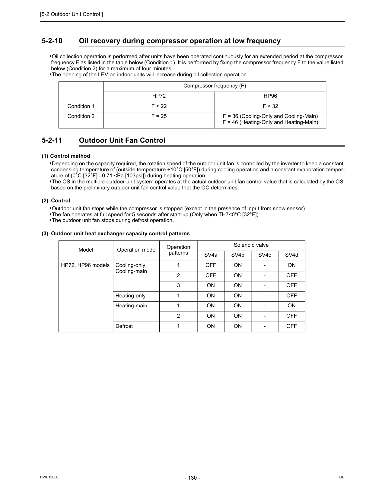
[5-2 Outdoor Unit Control ]
Hwe13080
Gb
5-2-10 Oil recovery during compressor operation at low frequency Oil collection operation is performed after units have been operated continuously for an extended period at the compressor frequency F as listed in the table below (Condition 1). It is performed by fixing the compressor frequency F to the value listed below (Condition 2) for a maximum of four minutes. The opening of the LEV on indoor units will increase during oil collection operation. 5-2-11 Outdoor Unit Fan Control (1) Control method Depending on the capacity required, the rotation speed of the outdoor unit fan is controlled by the inverter to keep a constant condensing temperature of (outside temperature +10°C [50°F]) during cooling operation and a constant evaporation temper- ature of (0°C [32°F] =0.71Hp96
Condition 1F < 22
F < 32
Condition 2F = 25
F = 36 (Cooling-Only and Cooling-Main) F = 46 (Heating-Only and Heating-Main) Model Operation mode Operation patterns Solenoid valve SV4a SV4b SV4c SV4d HP72, HP96 models Cooling-only Cooling-main 1Off
On
On
Off
On
Off
On
On
Off
On
On
Off
On
On
On
On
On
Off
On
On
Off
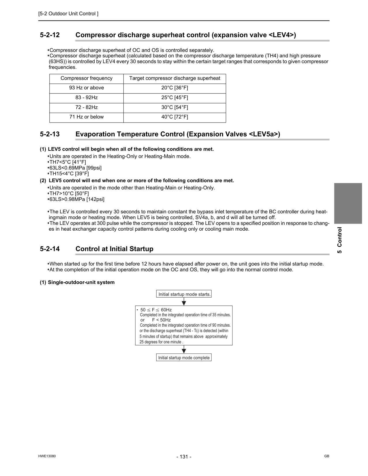
[5-2 Outdoor Unit Control ]
Hwe13080
Gb
5 Control 5-2-12 Compressor discharge superheat control (expansion valveTh7<5°C [41°F]
63LS<0.69MPa [99psi]Th15<4°C [39°F]
(2) LEV5 control will end when one or more of the following conditions are met. Units are operated in the mode other than Heating-Main or Heating-Only.Th7>10°C [50°F]
63LS>0.98MPa [142psi] The LEV is controlled every 30 seconds to maintain constant the bypass inlet temperature of the BC controller during heat- ingmain mode or heating mode. When LEV5 is being controlled, SV4a, b, and d will all be turned off. The LEV operates at 300 pulse while the compressor is stopped. The LEV opens to a specified position in response to chang- es in heat exchanger capacity control patterns during cooling only or cooling main mode. 5-2-14 Control at Initial Startup When started up for the first time before 12 hours have elapsed after power on, the unit goes into the initial startup mode. At the completion of the initial operation mode on the OC and OS, they will go into the normal control mode. (1) Single-outdoor-unit system Compressor frequency Target compressor discharge superheat 93 Hz or above20°C [36°F]
83 - 92Hz25°C [45°F]
72 - 82Hz30°C [54°F]
71 Hz or below40°C [72°F]
50 F 60Hz or F < 50Hz Initial startup mode starts. Completed in the integrated operation time of 35 minutes. Initial startup mode complete or the discharge superheat (TH4 - Tc) is detected (within 5 minutes of startup) that remains above approximately 25 degrees for one minute . Completed in the integrated operation time of 90 minutes.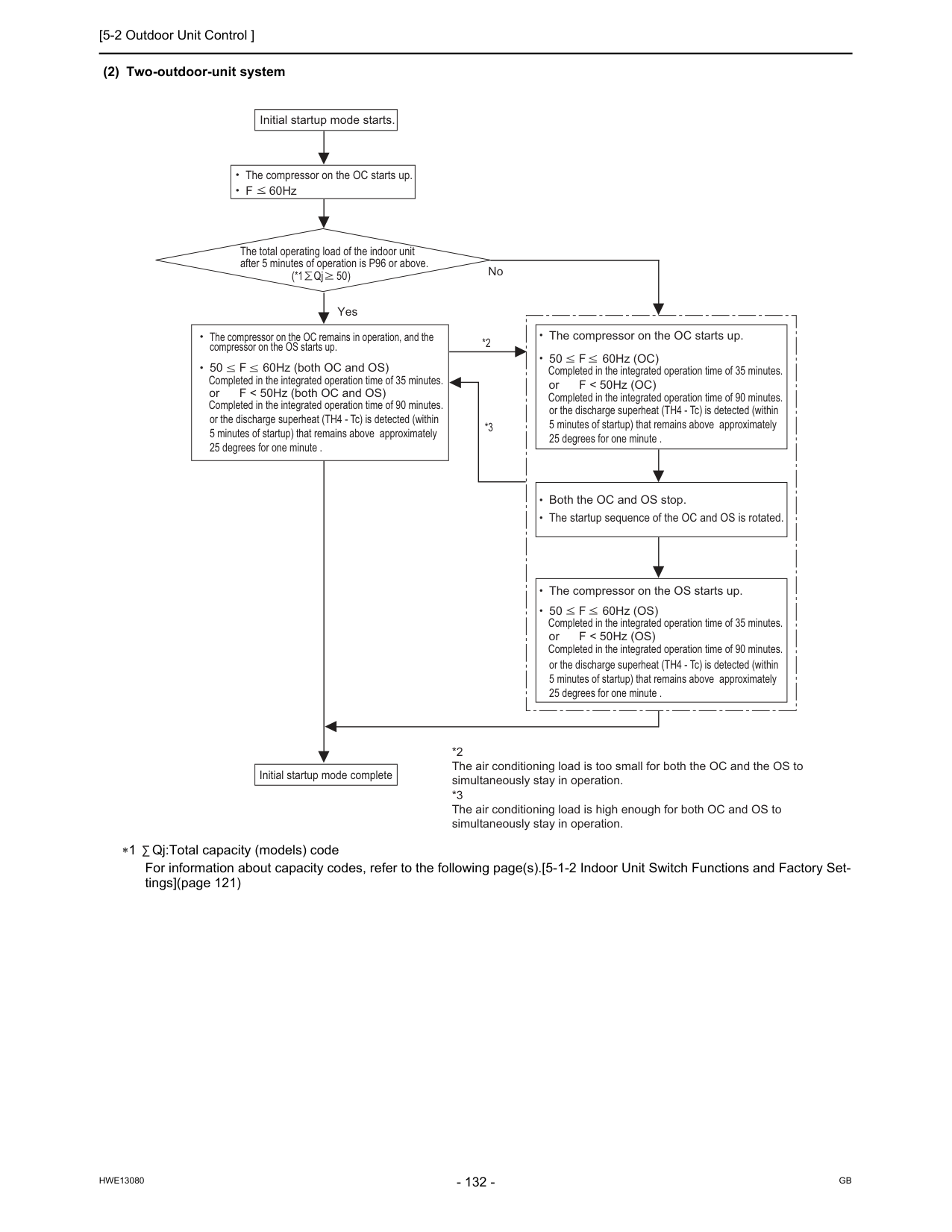
[5-2 Outdoor Unit Control ]
Hwe13080
Gb
(2) Two-outdoor-unit system ∗1 Qj:Total capacity (models) code For information about capacity codes, refer to the following page(s).[5-1-2 Indoor Unit Switch Functions and Factory Set- tings](page 121) The compressor on the OC starts up. The total operating load of the indoor unit after 5 minutes of operation is P96 or above. (*1 Qj 50) Initial startup mode starts. F 60Hz Yes No or F < 50Hz (both OC and OS) Completed in the integrated operation time of 90 minutes. The compressor on the OC remains in operation, and the compressor on the OS starts up. or F < 50Hz (OC) Completed in the integrated operation time of 90 minutes. The compressor on the OC starts up. Both the OC and OS stop. The startup sequence of the OC and OS is rotated. or F < 50Hz (OS) Completed in the integrated operation time of 90 minutes. The compressor on the OS starts up. *2 *3 *2 The air conditioning load is too small for both the OC and the OS to simultaneously stay in operation. *3 The air conditioning load is high enough for both OC and OS to simultaneously stay in operation. Initial startup mode complete or the discharge superheat (TH4 - Tc) is detected (within 5 minutes of startup) that remains above approximately 25 degrees for one minute . or the discharge superheat (TH4 - Tc) is detected (within 5 minutes of startup) that remains above approximately 25 degrees for one minute . or the discharge superheat (TH4 - Tc) is detected (within 5 minutes of startup) that remains above approximately 25 degrees for one minute . 50 F 60Hz (both OC and OS) Completed in the integrated operation time of 35 minutes. 50 F 60Hz (OC) Completed in the integrated operation time of 35 minutes. 50 F 60Hz (OS) Completed in the integrated operation time of 35 minutes.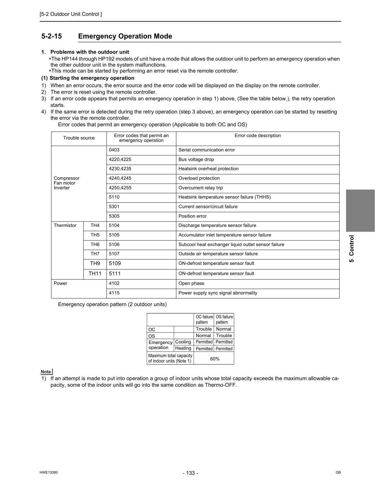
[5-2 Outdoor Unit Control ]
Hwe13080
Gb
5 Control 5-2-15 Emergency Operation ModeTh4
5104 Discharge temperature sensor failureTh5
5105 Accumulator inlet temperature sensor failureTh6
5106 Subcool heat exchanger liquid outlet sensor failureTh7
5107 Outside air temperature sensor failureTh9
5109 ON-defrost temperature sensor faultTh11
5111 ON-defrost temperature sensor fault Power 4102 Open phase 4115 Power supply sync signal abnormalityOc
OC failure pattern Trouble Normal Permitted Permitted Permitted Permitted 60% Cooling Heating Normal Trouble OS failure patternOs
Emergency operation Maximum total capacity of indoor units (Note 1)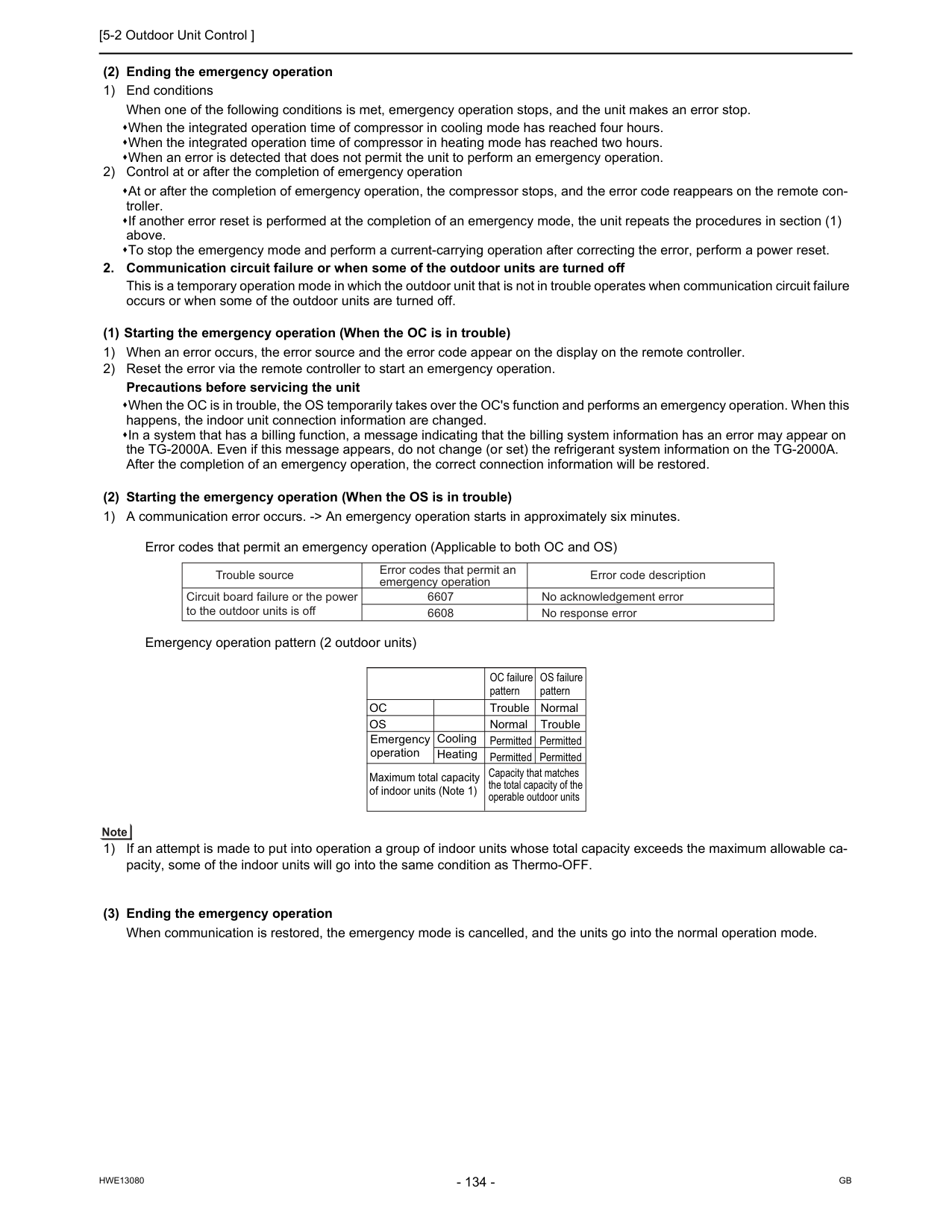
[5-2 Outdoor Unit Control ]
Hwe13080
Gb
(2) Ending the emergency operation 1) End conditions When one of the following conditions is met, emergency operation stops, and the unit makes an error stop. When the integrated operation time of compressor in cooling mode has reached four hours. When the integrated operation time of compressor in heating mode has reached two hours. When an error is detected that does not permit the unit to perform an emergency operation. 2) Control at or after the completion of emergency operation At or after the completion of emergency operation, the compressor stops, and the error code reappears on the remote con- troller. If another error reset is performed at the completion of an emergency mode, the unit repeats the procedures in section (1) above. To stop the emergency mode and perform a current-carrying operation after correcting the error, perform a power reset.Oc
Cooling Heating OC failure pattern Trouble Normal Permitted Permitted Permitted Permitted Normal Trouble OS failure patternOs
Emergency operation Maximum total capacity of indoor units (Note 1) Capacity that matches the total capacity of the operable outdoor units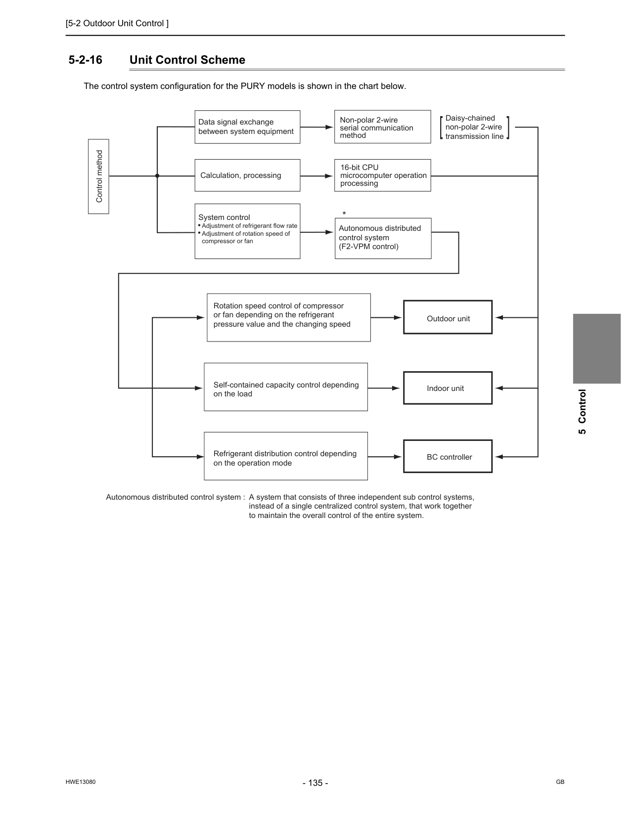
[5-2 Outdoor Unit Control ]
Hwe13080
Gb
5 Control 5-2-16 Unit Control Scheme The control system configuration for the PURY models is shown in the chart below. Control method Data signal exchange between system equipment Calculation, processing System control Adjustment of refrigerant flow rate Adjustment of rotation speed of compressor or fan Non-polar 2-wire serial communication method 16-bit CPU microcomputer operation processing Autonomous distributed control system (F2-VPM control) Rotation speed control of compressor or fan depending on the refrigerant pressure value and the changing speed Self-contained capacity control depending on the load Refrigerant distribution control depending on the operation mode Outdoor unit Daisy-chained non-polar 2-wire transmission line Indoor unit BC controller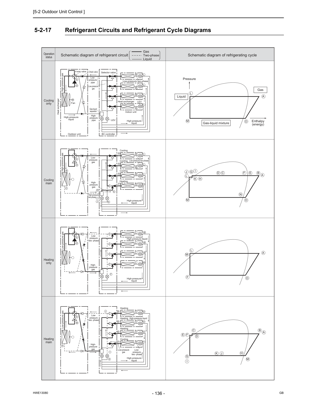
[5-2 Outdoor Unit Control ]
Hwe13080
Gb
5-2-17 Refrigerant Circuits and Refrigerant Cycle Diagrams High-pressure gas High-pressure gas Heat exchanger High-pressure liquid Fan 4-way valve Check valve Selector valve Low-pressure two-phase Low-pressure two-phase Low- pressure two- phase High-pressure liquid Low- pressure two- phase Low- pressure two- phase Heat exchanger High-pressure liquid High-pressure liquid High-pressure liquid High-pressure liquid High-pressure liquid Cooling Cooling Cooling Heating Cooling Heating Heating Heating Low- pressure pipe High- pressure pipe High- pressure gas High- pressure gas High- pressure gas High-pressure two-phase Low-pressure gas Low-pressure gas Low-pressure gas Low-pressure gas Low- pressure gas Gas-liquid separator Outdoor unit BC controller Indoor unitLev
Lev
M
M
L
M
L
M
L
M
L
A
O
M
L
M
L
M
L
M
L
A
O
B
C
D
I
J
J
E
F
F
N
N
N
K
M
L
M
L
M
L
G
H
A
O
L
J
G
I
K
H
D
C
F
E
B
N
A
M
O
J
G
I
K
H
D
C
F
E
B A
M
L
F
M
A
O
M
L
A
O
M
A
I
E
K
B
C
D
B
C
D
B
C
D
F
G
H
Gas-liquid mixture Pressure Liquid Gas Enthalpy (energy) Schematic diagram of refrigerant circuit Gas Two-phase Liquid Schematic diagram of refrigerating cycle Cooling only Operation status Cooling main Heating only Heating main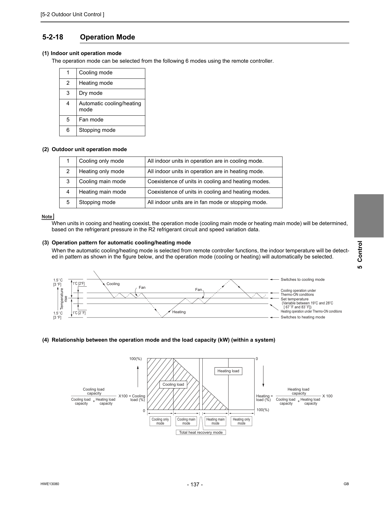
[5-2 Outdoor Unit Control ]
Hwe13080
Gb
5 Control 5-2-18 Operation Mode (1) Indoor unit operation mode The operation mode can be selected from the following 6 modes using the remote controller. (2) Outdoor unit operation mode When units in cooing and heating coexist, the operation mode (cooling main mode or heating main mode) will be determined, based on the refrigerant pressure in the R2 refrigerant circuit and speed variation data. (3) Operation pattern for automatic cooling/heating mode When the automatic cooling/heating mode is selected from remote controller functions, the indoor temperature will be detect- ed in pattern as shown in the figure below, and the operation mode (cooling or heating) will automatically be selected. (4) Relationship between the operation mode and the load capacity (kW) (within a system) 1 Cooling mode 2 Heating mode 3 Dry mode 4 Automatic cooling/heating mode 5 Fan mode 6 Stopping mode 1 Cooling only mode All indoor units in operation are in cooling mode. 2 Heating only mode All indoor units in operation are in heating mode. 3 Cooling main mode Coexistence of units in cooling and heating modes. 4 Heating main mode Coexistence of units in cooling and heating modes. 5 Stopping mode All indoor units are in fan mode or stopping mode. Cooling Fan Heating Switches to cooling mode Cooling operation under Thermo-ON conditions Set temperature (Variable between 19 C and 28 C [ 67 F and 83 F]) Heating operation under Thermo-ON conditions Switches to heating mode Fan Temperature rise1.5 C
[3 F]
1.5 C
[3 F]
1 C [2 F]
1 C [2 F]
Cooling load capacity Heating load capacity + Cooling load capacity Heating load capacity Heating load capacity + Cooling load capacity 100(%) Cooling only mode Cooling main mode Heating main mode Total heat recovery mode Heating only mode 100(%) Heating load (%) Heating load X100 = Cooling load (%) = Cooling loadX 100
0 0
[5-2 Outdoor Unit Control ]
Hwe13080
Gb
5-2-19 Demand Control Cooling/heating operation can be prohibited (Thermo-OFF) by an external input to the indoor units. When DIP SW6-8 is set to ON, the 4-step DEMAND control is enabled. Eight-step demand control is possible in the system with two outdoor units. For details, refer to the following page(s). [2-4-7 Various Control Methods Using the Signal Input/Output Connector on Outdoor Unit](page 26)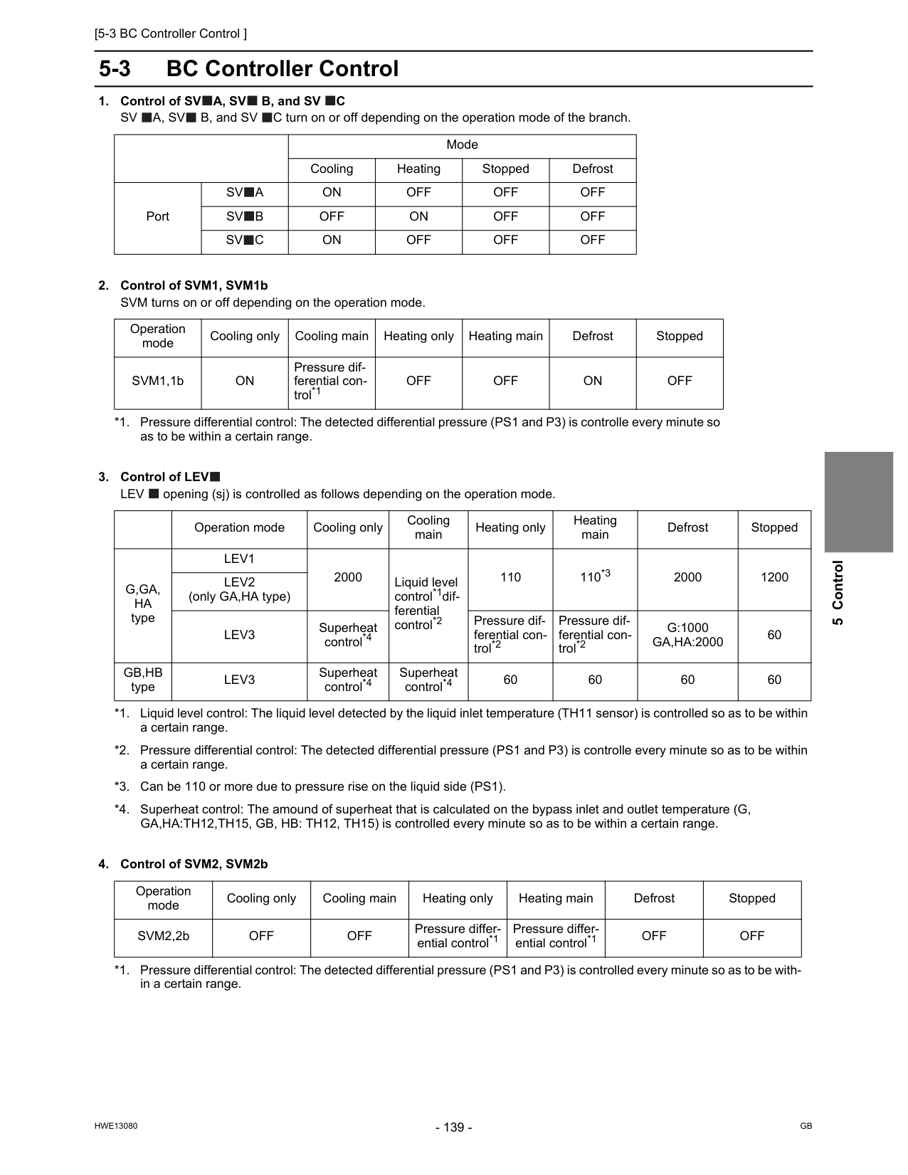
[5-3 BC Controller Control ]
Hwe13080
Gb
5 Control 5-3 BC Controller ControlA, Sv
B, and SVC
Sv
A, Sv
B, and SV C turn on or off depending on the operation mode of the branch.Lev
opening (sj) is controlled as follows depending on the operation mode.Sv
A
On
Off
Off
Off
Sv
B
Off
On
Off
Off
Sv
C
On
Off
Off
Off
Operation mode Cooling only Cooling main Heating only Heating main Defrost Stopped SVM1,1bOn
Pressure dif- ferential con- trol*1 *1. Pressure differential control: The detected differential pressure (PS1 and P3) is controlle every minute so as to be within a certain range.Off
Off
On
Off
Operation mode Cooling only Cooling main Heating only Heating main Defrost StoppedG,Ga,
Ha
typeLev1
2000 Liquid level control*1dif- ferential control*2 *1. Liquid level control: The liquid level detected by the liquid inlet temperature (TH11 sensor) is controlled so as to be within a certain range. *2. Pressure differential control: The detected differential pressure (PS1 and P3) is controlle every minute so as to be within a certain range. 110 110*3 *3. Can be 110 or more due to pressure rise on the liquid side (PS1). 2000 1200Lev2
(only GA,HA type)Lev3
Superheat control*4 *4. Superheat control: The amound of superheat that is calculated on the bypass inlet and outlet temperature (G, GA,HA:TH12,TH15, GB, HB: TH12, TH15) is controlled every minute so as to be within a certain range. Pressure dif- ferential con- trol*2 Pressure dif- ferential con- trol*2G:1000
Ga,Ha:2000
60Gb,Hb
typeLev3
Superheat control*4 Superheat control*4 60 60 60 60 Operation mode Cooling only Cooling main Heating only Heating main Defrost Stopped SVM2,2bOff
Off
Pressure differ- ential control*1 *1. Pressure differential control: The detected differential pressure (PS1 and P3) is controlled every minute so as to be with- in a certain range. Pressure differ- ential control*1Off
Off
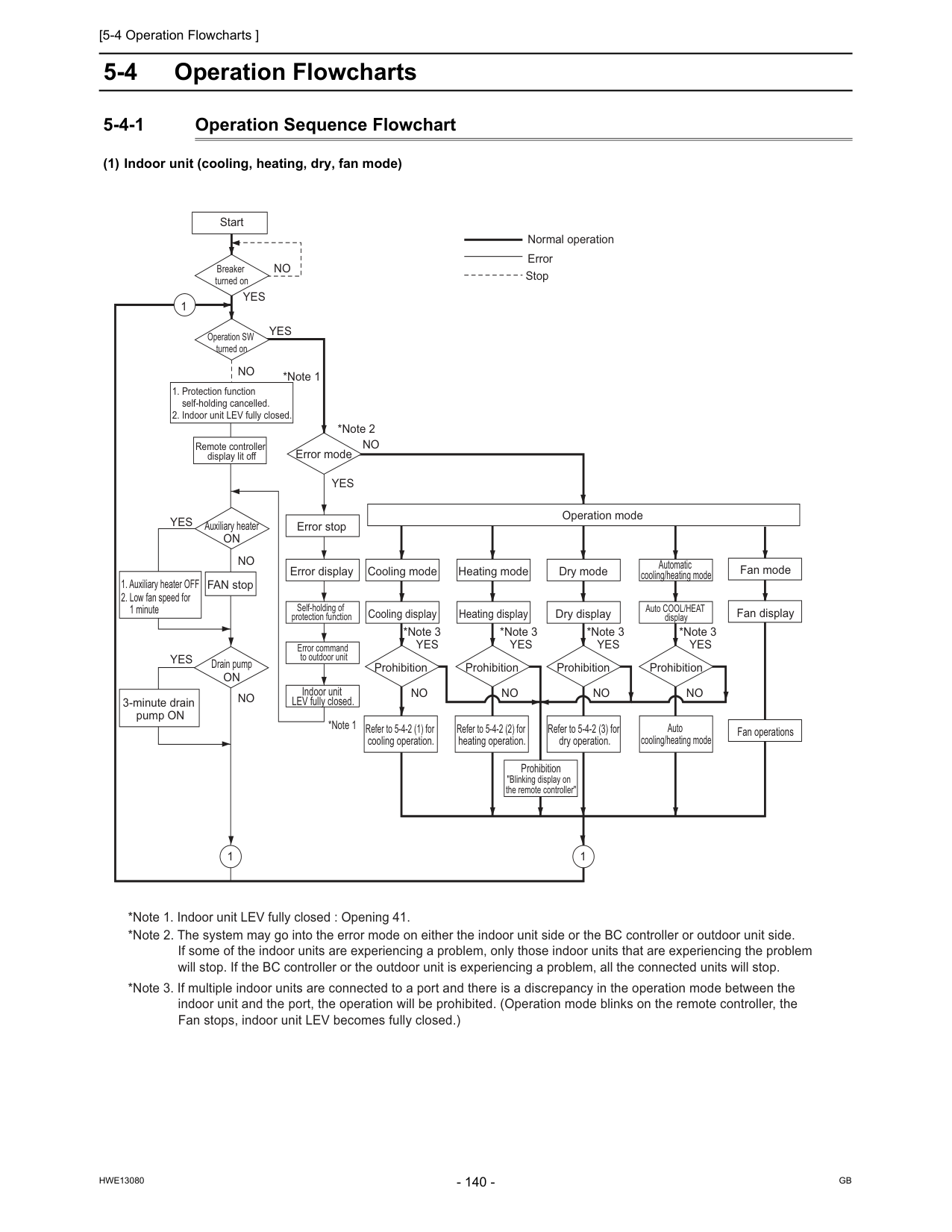
[5-4 Operation Flowcharts ]
Hwe13080
Gb
5-4 Operation Flowcharts 5-4-1 Operation Sequence Flowchart (1) Indoor unit (cooling, heating, dry, fan mode) Start Remote controller display lit off Error mode Error stop Error display Self-holding of protection function Error command to outdoor unit Indoor unit LEV fully closed. Refer to 5-4-2 (1) for cooling operation. Refer to 5-4-2 (2) for heating operation. Refer to 5-4-2 (3) for dry operation. Prohibition Prohibition Prohibition Dry display Heating display Cooling display Dry mode Heating mode Fan mode Fan display Fan operationsOperation mode Cooling mode Prohibition "Blinking display on the remote controller" FAN stop Breaker turned on Operation SW turned on Auxiliary heater
On
Drain pumpOn
3-minute drain pump ONNo
No
No
No
No
No
No
No
No
*Note 1 *Note 1 *Note 2 *Note 3 *Note 3 *Note 3Yes
Yes
Yes
Yes
Yes
Yes
Yes
Yes
Normal operation Error Stop 1 Prohibition Auto COOL/HEAT display Automatic cooling/heating mode *Note 3Yes
Auto cooling/heating mode 1 1 *Note 1. Indoor unit LEV fully closed : Opening 41. *Note 2. The system may go into the error mode on either the indoor unit side or the BC controller or outdoor unit side. If some of the indoor units are experiencing a problem, only those indoor units that are experiencing the problem will stop. If the BC controller or the outdoor unit is experiencing a problem, all the connected units will stop. *Note 3. If multiple indoor units are connected to a port and there is a discrepancy in the operation mode between the indoor unit and the port, the operation will be prohibited. (Operation mode blinks on the remote controller, the Fan stops, indoor unit LEV becomes fully closed.)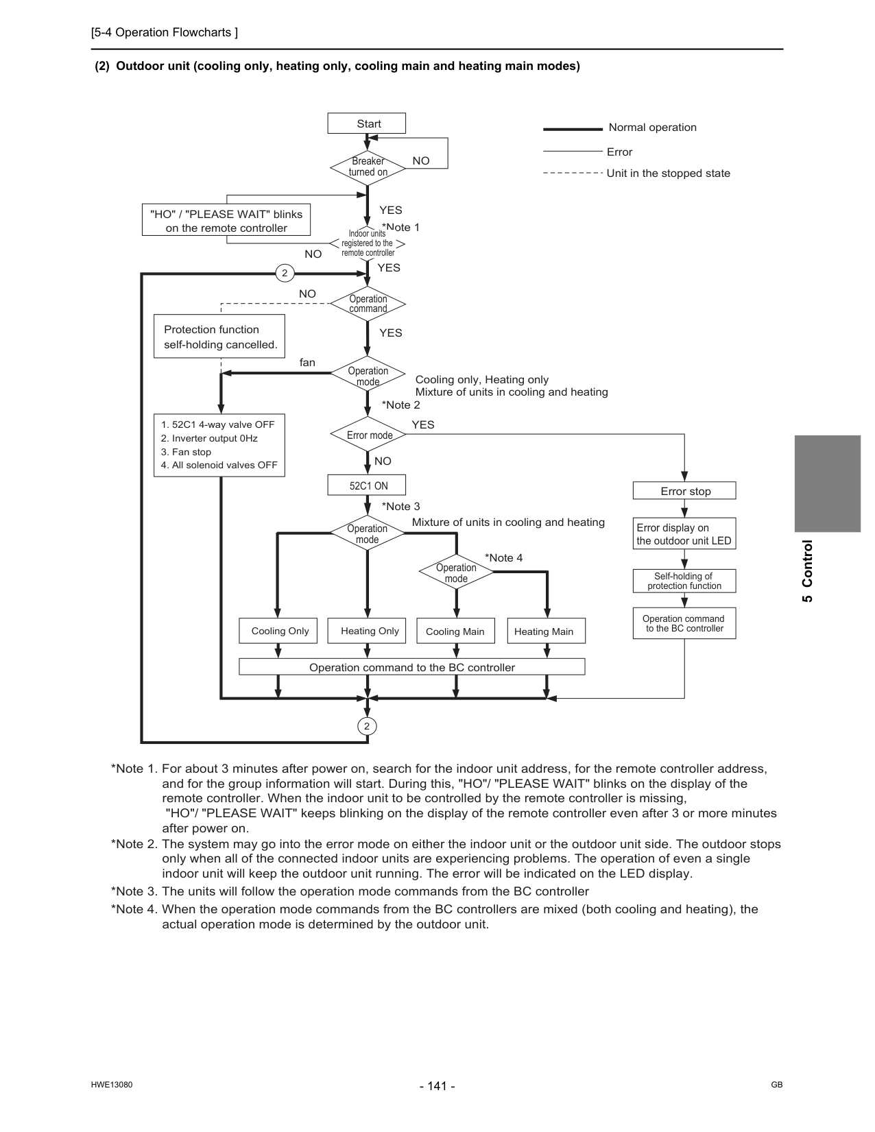
[5-4 Operation Flowcharts ]
Hwe13080
Gb
5 Control (2) Outdoor unit (cooling only, heating only, cooling main and heating main modes) Start Breaker turned on Operation command Error stop Error display on the outdoor unit LED Self-holding of protection function Operation command to the BC controller Operation mode Error mode52C1 On
*Note 1 *Note 2 *Note 3 *Note 4Yes
Yes
Yes
Yes
No
No
No
fanNo
"HO" / "PLEASE WAIT" blinks on the remote controller Operation command to the BC controller Cooling only, Heating only Mixture of units in cooling and heating Mixture of units in cooling and heating Protection function self-holding cancelled. Normal operationOperation mode Operation mode *Note 1. For about 3 minutes after power on, search for the indoor unit address, for the remote controller address, and for the group information will start. During this, "HO"/ "PLEASE WAIT" blinks on the display of the remote controller. When the indoor unit to be controlled by the remote controller is missing, "HO"/ "PLEASE WAIT" keeps blinking on the display of the remote controller even after 3 or more minutes after power on. *Note 3. The units will follow the operation mode commands from the BC controller *Note 4. When the operation mode commands from the BC controllers are mixed (both cooling and heating), the actual operation mode is determined by the outdoor unit. *Note 2. The system may go into the error mode on either the indoor unit or the outdoor unit side. The outdoor stops only when all of the connected indoor units are experiencing problems. The operation of even a single indoor unit will keep the outdoor unit running. The error will be indicated on the LED display. Heating Main Indoor units registered to the remote controller Error Unit in the stopped state
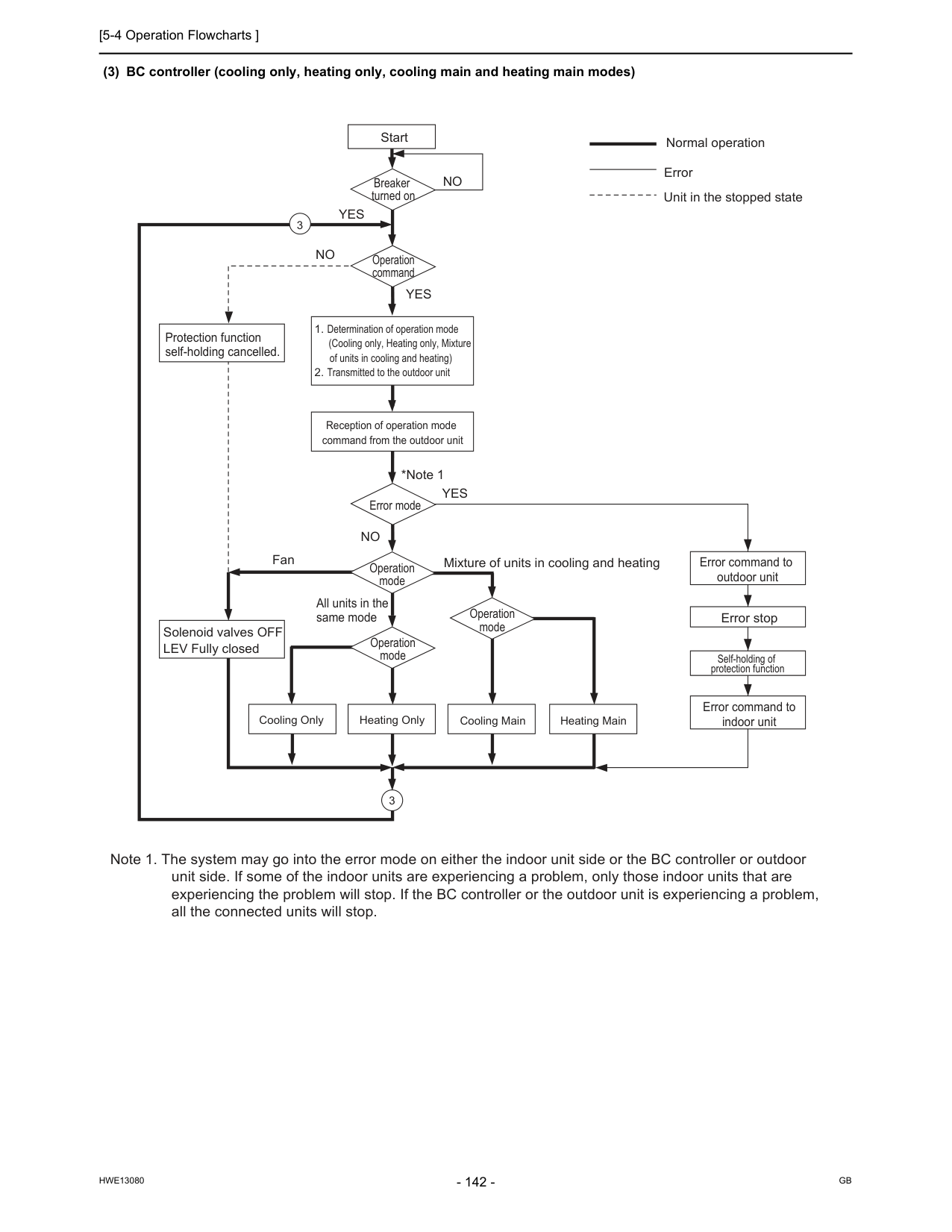
[5-4 Operation Flowcharts ]
Hwe13080
Gb
(3) BC controller (cooling only, heating only, cooling main and heating main modes) Start Breaker turned on Operation command Error command to outdoor unit Error stop Self-holding of protection function Error command to indoor unit Error mode *Note 1Yes
Yes
Yes
No
No
FanNo
All units in the same mode Solenoid valves OFF LEV Fully closed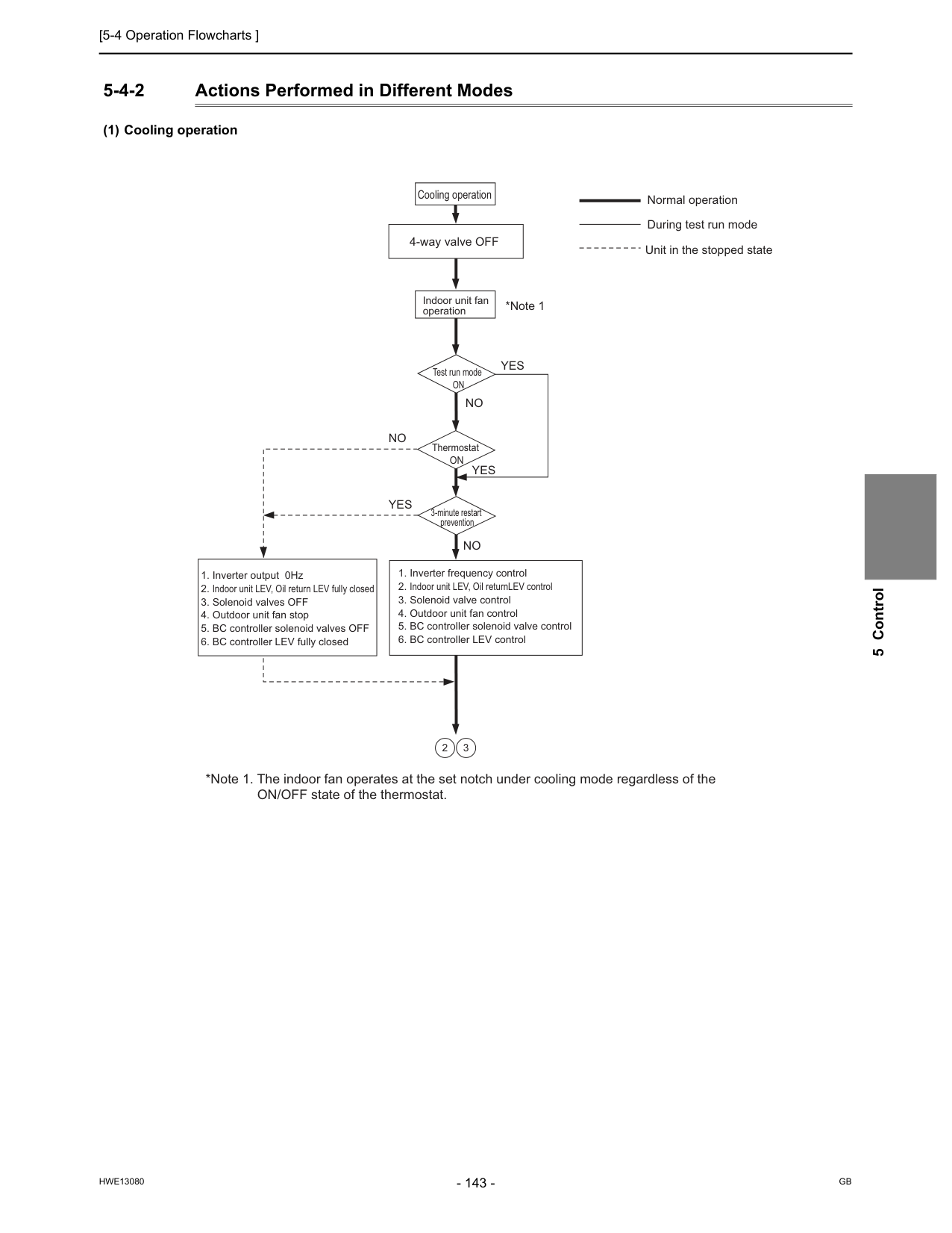
[5-4 Operation Flowcharts ]
Hwe13080
Gb
5 Control 5-4-2 Actions Performed in Different Modes (1) Cooling operation Cooling operation Test run modeOn
ThermostatOn
3-minute restart prevention *Note 1Yes
Yes
Yes
No
No
No
4-way valve OFF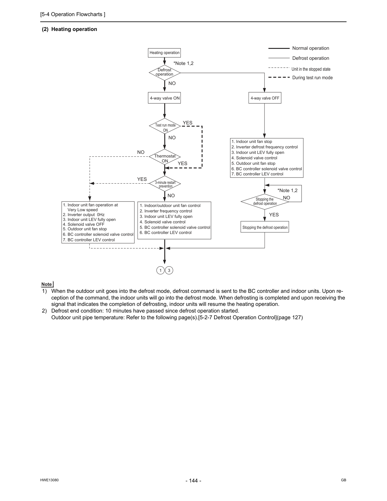
[5-4 Operation Flowcharts ]
Hwe13080
Gb
(2) Heating operation 1) When the outdoor unit goes into the defrost mode, defrost command is sent to the BC controller and indoor units. Upon re- ception of the command, the indoor units will go into the defrost mode. When defrosting is completed and upon receiving the signal that indicates the completion of defrosting, indoor units will resume the heating operation. 2) Defrost end condition: 10 minutes have passed since defrost operation started. Outdoor unit pipe temperature: Refer to the following page(s).[5-2-7 Defrost Operation Control](page 127) Heating operation Test run modeOn
ThermostatOn
Defrost operation 3-minute restart prevention *Note 1,2 *Note 1,2Yes
Yes
Yes
Yes
No
No
No
No
No
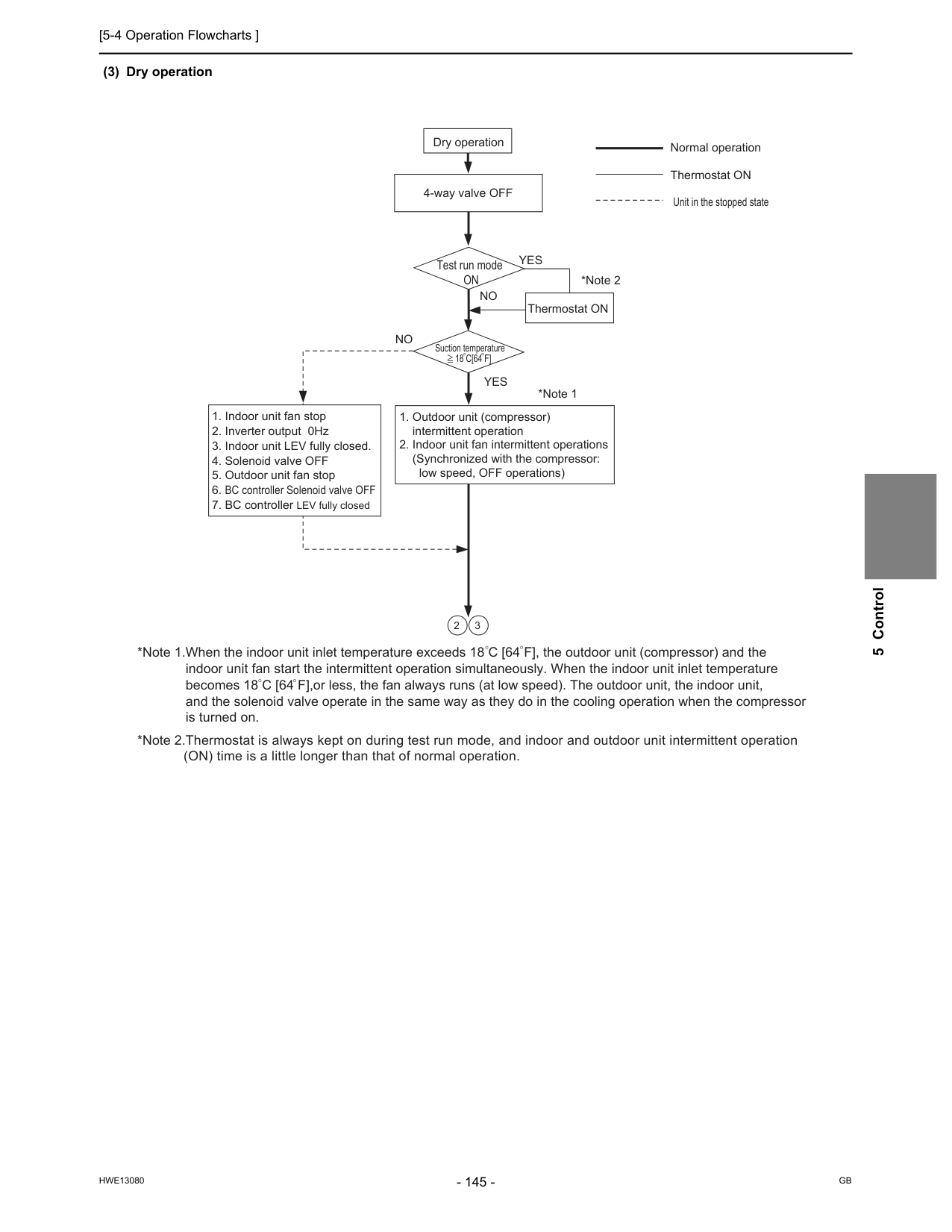
[5-4 Operation Flowcharts ]
Hwe13080
Gb
5 Control (3) Dry operation Dry operation *Note 1 *Note 2Yes
Yes
No
No
4-way valve OFFOn
Suction temperature18 C[64 F]
Unit in the stopped state
[5-4 Operation Flowcharts ]
Hwe13080
Gb
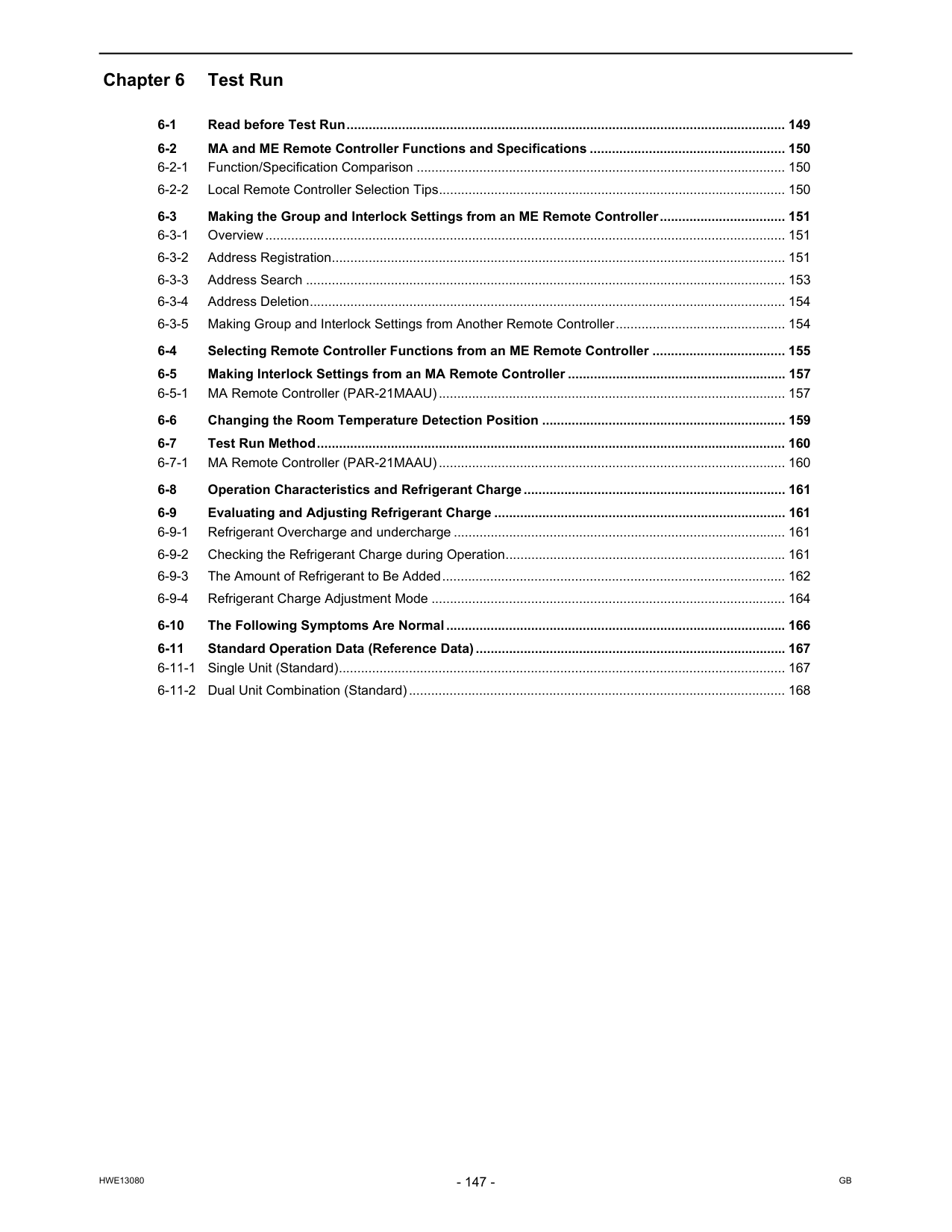
Hwe13080
Gb
Chapter 6 Test Run 6-1 Read before Test Run....................................................................................................................... 149 6-2 MA and ME Remote Controller Functions and Specifications ..................................................... 150 6-2-1 Function/Specification Comparison .................................................................................................... 150 6-2-2 Local Remote Controller Selection Tips.............................................................................................. 150 6-3 Making the Group and Interlock Settings from an ME Remote Controller.................................. 151 6-3-1 Overview............................................................................................................................................. 151 6-3-2 Address Registration........................................................................................................................... 151 6-3-3 Address Search .................................................................................................................................. 153 6-3-4 Address Deletion................................................................................................................................. 154 6-3-5 Making Group and Interlock Settings from Another Remote Controller.............................................. 154 6-4 Selecting Remote Controller Functions from an ME Remote Controller .................................... 155 6-5 Making Interlock Settings from an MA Remote Controller ........................................................... 157 6-5-1 MA Remote Controller (PAR-21MAAU).............................................................................................. 157 6-6 Changing the Room Temperature Detection Position .................................................................. 159 6-7 Test Run Method............................................................................................................................... 160 6-7-1 MA Remote Controller (PAR-21MAAU).............................................................................................. 160 6-8 Operation Characteristics and Refrigerant Charge....................................................................... 161 6-9 Evaluating and Adjusting Refrigerant Charge ............................................................................... 161 6-9-1 Refrigerant Overcharge and undercharge .......................................................................................... 161 6-9-2 Checking the Refrigerant Charge during Operation............................................................................ 161 6-9-3 The Amount of Refrigerant to Be Added............................................................................................. 162 6-9-4 Refrigerant Charge Adjustment Mode ................................................................................................ 164 6-10 The Following Symptoms Are Normal............................................................................................ 166 6-11 Standard Operation Data (Reference Data).................................................................................... 167 6-11-1 Single Unit (Standard)......................................................................................................................... 167 6-11-2 Dual Unit Combination (Standard)...................................................................................................... 168
Hwe13080
Gb
[6-1 Read before Test Run ]
Hwe13080
Gb
6 Test Run 6 Test Run6-1 Read before Test Run (1) Check for refrigerant leak and loose cables and connectors. (2) When opening or closing the front panel of the control box, do not let it come into contact with any of the internal components. Before inspecting the inside of the control box, turn off the power, keep the unit off for at least 10 minutes, and confirm that the capacitor voltage (inverter main circuit) has dropped to 20 VDC or less. (It takes about 10 minutes to discharge electricity after the power supply is turned off.) Control box houses high temperature parts. Be well careful even after turning off the power source. Perform the service after disconnecting the outdoor unit fan board connector (CNINV) and the inverter board connector (CN1). (To plug or unplugconnectors, check that the outdoor unit fan is not rotating and that the voltage of capacitor in the main circuit is 20 VDC or below. The capacitor may collect a charge and cause an electric shock when the outdoor unit fan rotates in windy conditions. Refer to the wiring nameplate for details.) To connect wiring to TB7, check that the voltage is 20 VDC or below. Reconnect the connector (CNINV) back to the fan board and reconnect the connector (CN1) back to the inverter board after servicing. (3) Measure the insulation resistance between the power supply terminal block and the ground with a 500V megger and make sure it reads at least 1.0Mohm. Do not operate the unit if the insulation resistance is below 1.0Mohm. Do not apply megger voltage to the terminal block for transmission line. Doing so will damage the controller board. The insulation resistance between the power supply terminal block and the ground could go down to close to 1Mohm imme- diately after installation or when the power is kept off for an extended period of time because of the accumulation of refrigerant in the compressor. If insulation resistance reads at least 1 MΩ, by turning on the main power and keeping it on for at least 12 hours, the refrigerant in the compressor will evaporate and the insulation resistance will go up. Do not measure the insulation resistance of the terminal block for transmission line for the unit remote controller. (4) When the power is turned on, the compressor is energized even while it is not operating. Before turning on the power, disconnect all power supply wires from the compressor terminal block, and measure the insula- tion resistance of the compressor. Check the compressor for a ground fault. If the insulation resistance is 1.0 MΩ or below, connect all power supply wires to the compressor and turn on the power to the outdoor unit. (The liquid refrigerant in the compressor will evaporate by energiz- ing the compressor.) (5) Make sure the valves on both the high-pressure and low-pressure sides are fully open. Securely tighten the cap. (6) Check the phase sequence and the voltage of the power supply. When the voltage is out of the ±10% range, or when the phase voltage difference is more than 2%, please discuss the coun- termeasure with the customer. (7) [When a transmission booster is connected] Turn on the transmission booster before turning on the outdoor units. If the outdoor units are turned on first, the connection information for the refrigerant circuit may not be properly recognized. In case the outdoor units are turned on before the transmission booster is turned on, perform a power reset on the outdoor units after turning on the power booster. (8) Turn on the main power at least 12 hours before test run. Insufficient powering time may result in compressor damage. (9) When a power supply unit is connected to the transmission line for centralized control(*), perform a test run with the power supply unit being energized. Leave the power jumper connector on CN41 as it is (factory setting). *Includes the cases where power is supplied to the transmission line from a system controller with a power-supply function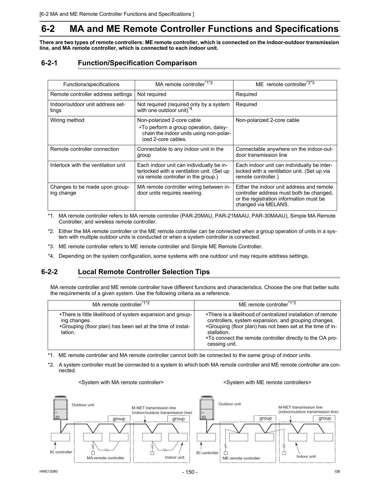
[6-2 MA and ME Remote Controller Functions and Specifications ]
Hwe13080
Gb
6-2 MA and ME Remote Controller Functions and Specifications There are two types of remote controllers: ME remote controller, which is connected on the indoor-outdoor transmission line, and MA remote controller, which is connected to each indoor unit. 6-2-1 Function/Specification Comparison 6-2-2 Local Remote Controller Selection Tips MA remote controller and ME remote controller have different functions and characteristics. Choose the one that better suits the requirements of a given system. Use the following criteria as a reference. Functions/specifications MA remote controller*1*2 *1. MA remote controller refers to MA remote controller (PAR-20MAU, PAR-21MAAU, PAR-30MAAU), Simple MA Remote Controller, and wireless remote controller. *2. Either the MA remote controller or the ME remote controller can be connected when a group operation of units in a sys- tem with multiple outdoor units is conducted or when a system controller is connected. ME remote controller*2*3 *3. ME remote controller refers to ME remote controller and Simple ME Remote Controller. Remote controller address settings Not required Required Indoor/outdoor unit address set- tings Not required (required only by a system with one outdoor unit)*4 *4. Depending on the system configuration, some systems with one outdoor unit may require address settings. Required Wiring method Non-polarized 2-core cable ∗To perform a group operation, daisy- chain the indoor units using non-polar- ized 2-core cables. Non-polarized 2-core cable Remote controller connection Connectable to any indoor unit in the group Connectable anywhere on the indoor-out- door transmission line Interlock with the ventilation unit Each indoor unit can individually be in- terlocked with a ventilation unit. (Set up via remote controller in the group.) Each indoor unit can individually be inter- locked with a ventilation unit. (Set up via remote controller.) Changes to be made upon group- ing change MA remote controller wiring between in- door units requires rewiring. Either the indoor unit address and remote controller address must both be changed, or the registration information must be changed via MELANS. MA remote controller*1*2 ME remote controller*1*2 There is little likelihood of system expansion and group- ing changes. Grouping (floor plan) has been set at the time of instal- lation. There is a likelihood of centralized installation of remote controllers, system expansion, and grouping changes. Grouping (floor plan) has not been set at the time of in- stallation. To connect the remote controller directly to the OA pro- cessing unit. *1. ME remote controller and MA remote controller cannot both be connected to the same group of indoor units. *2. A system controller must be connected to a system to which both MA remote controller and ME remote controller are con- nected.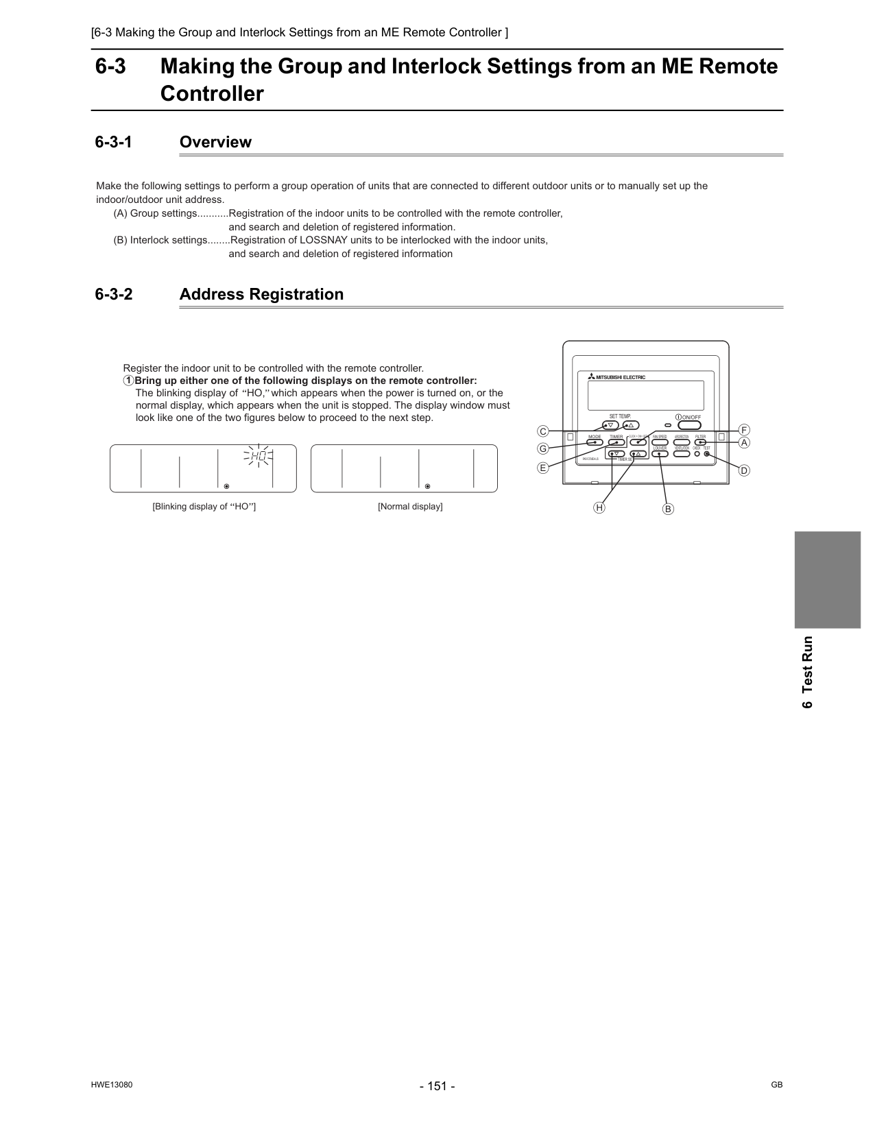
[6-3 Making the Group and Interlock Settings from an ME Remote Controller ]
Hwe13080
Gb
6 Test Run 6-3 Making the Group and Interlock Settings from an ME Remote Controller 6-3-1 Overview 6-3-2 Address Registration Make the following settings to perform a group operation of units that are connected to different outdoor units or to manually set up the indoor/outdoor unit address. (A) Group settings...........Registration of the indoor units to be controlled with the remote controller,and search and deletion of registered information. (B) Interlock settings........Registration of LOSSNAY units to be interlocked with the indoor units,
and search and deletion of registered information
[Normal display] Register the indoor unit to be controlled with the remote controller. Bring up either one of the following displays on the remote controller: The blinking display of HO, which appears when the power is turned on, or the normal display, which appears when the unit is stopped. The display window must look like one of the two figures below to proceed to the next step. 1 [Blinking display of HO ]
On/Off
Set Temp.
Par-F27Mea-Us
Filter
Check
Test
Clock
On
Off
Mode
Timer
Fan Speed
Louver
Ventilation
Air Direction
Timer Set
?A
F
D
B
H
G
C
E
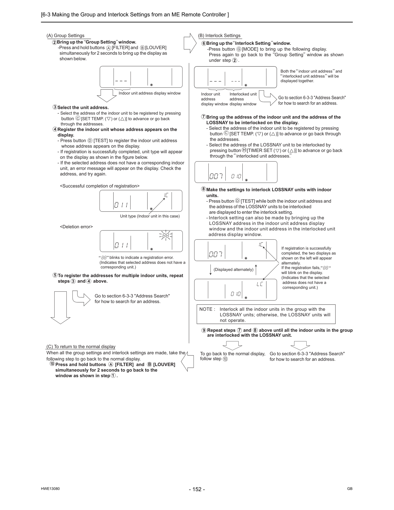
[6-3 Making the Group and Interlock Settings from an ME Remote Controller ]
Hwe13080
Gb
A
C
D
B
Select the unit address.Unit type (Indoor unit in this case) blinks to indicate a registration error. (Indicates that selected address does not have a corresponding unit.) 4 To register the addresses for multiple indoor units, repeat steps and above. 3 4 Go to section 6-3-3 "Address Search" for how to search for an address. Go to section 6-3-3 "Address Search" for how to search for an address. Bring up the Interlock Setting window. -Press button [MODE] to bring up the following display. Press again to go back to the Group Setting window as shown under step . 6
G
2 Both the indoor unit address and interlocked unit address will be displayed together. Bring up the address of the indoor unit and the address of the LOSSNAY to be interlocked on the display.C
H
Make the settings to interlock LOSSNAY units with indoor units.D
(Displayed alternately) If registration is successfully completed, the two displays as shown on the left will appear alternately. If the registration fails, will blink on the display. (Indicates that the selected address does not have a corresponding unit.) NOTE : Interlock all the indoor units in the group with the LOSSNAY units; otherwise, the LOSSNAY units will not operate. (C) To return to the normal display When all the group settings and interlock settings are made, take the following step to go back to the normal display. Press and hold buttons [FILTER] and [LOUVER] simultaneously for 2 seconds to go back to the window as shown in step . Repeat steps 7 and 8 above until all the indoor units in the group are interlocked with the LOSSNAY unit. To go back to the normal display, follow step Go to section 6-3-3 "Address Search" for how to search for an address. 10A
B
1 9 10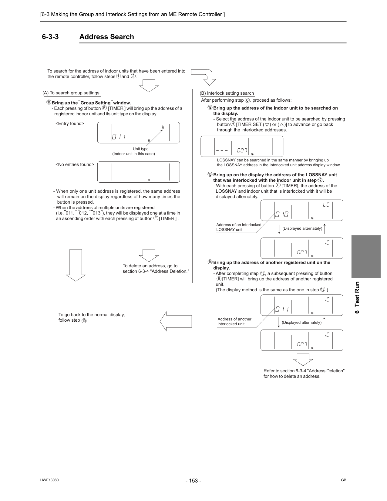
[6-3 Making the Group and Interlock Settings from an ME Remote Controller ]
Hwe13080
Gb
6 Test Run 6-3-3 Address SearchUnit type (Indoor unit in this case)
E
1 2E
10E
13 13 13 12 14 12 6E
H
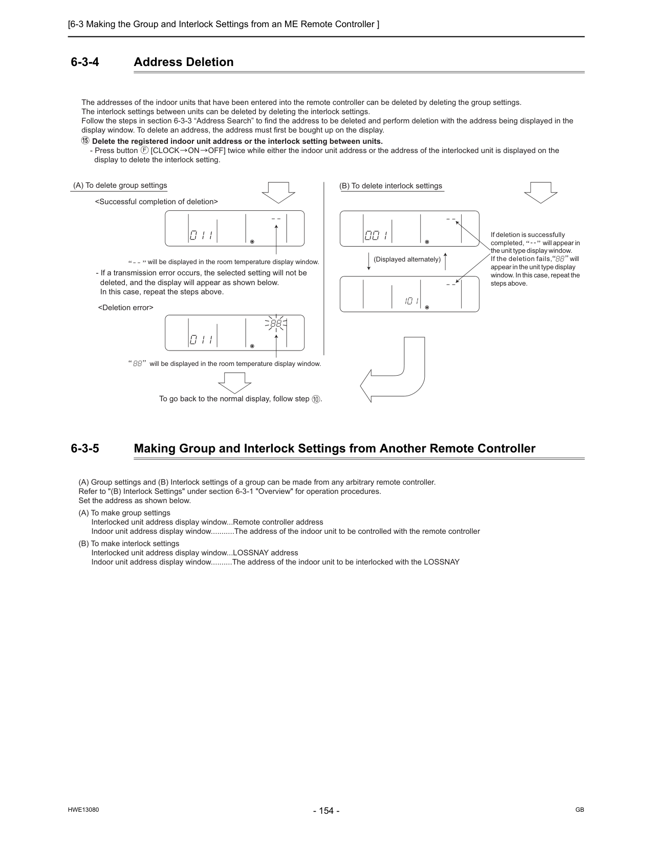
[6-3 Making the Group and Interlock Settings from an ME Remote Controller ]
Hwe13080
Gb
6-3-4 Address Deletion 6-3-5 Making Group and Interlock Settings from Another Remote Controller The addresses of the indoor units that have been entered into the remote controller can be deleted by deleting the group settings. The interlock settings between units can be deleted by deleting the interlock settings. Follow the steps in section 6-3-3 “Address Search” to find the address to be deleted and perform deletion with the address being displayed in the display window. To delete an address, the address must first be bought up on the display. Delete the registered indoor unit address or the interlock setting between units.F
15 (A) To delete group settings (B) To delete interlock settings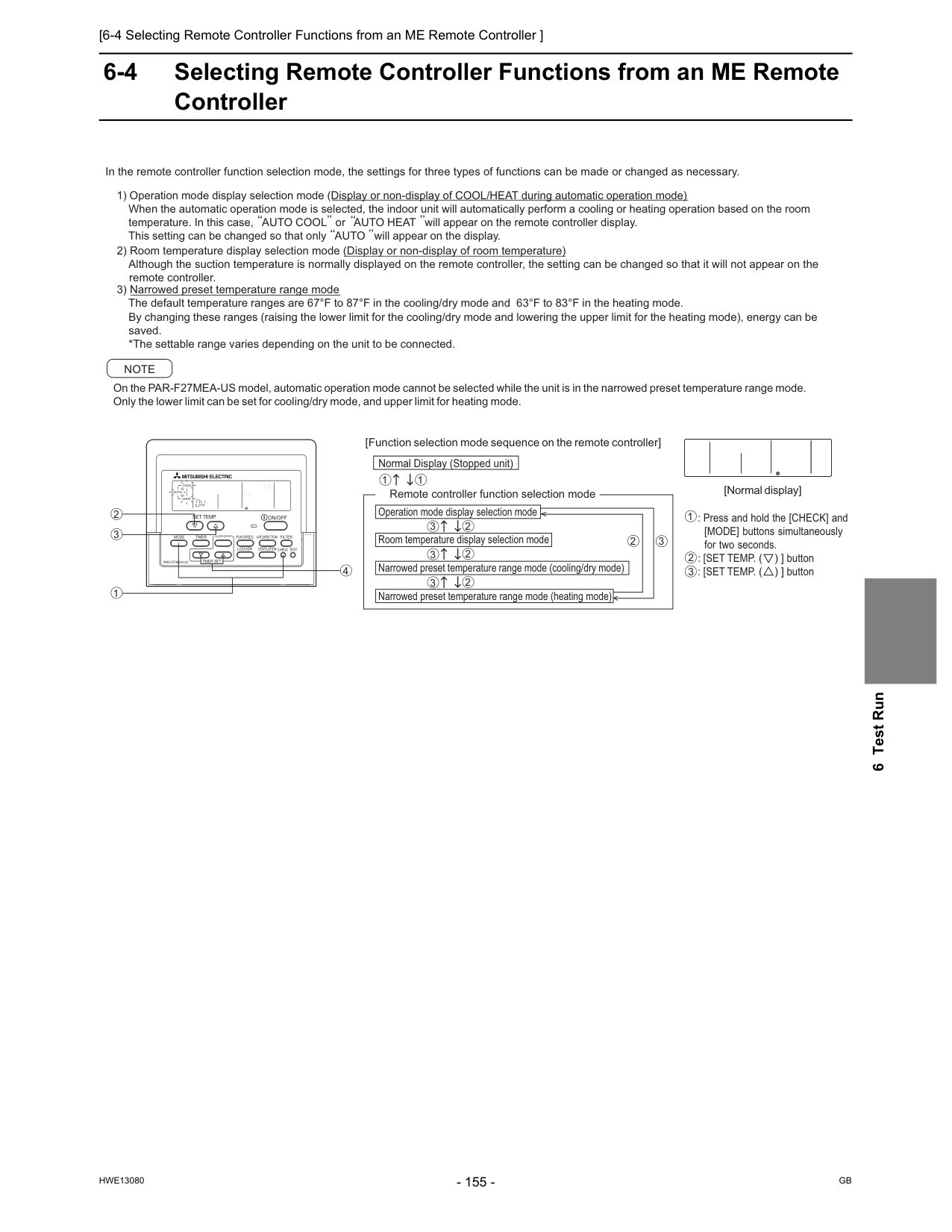
[6-4 Selecting Remote Controller Functions from an ME Remote Controller ]
Hwe13080
Gb
6 Test Run 6-4 Selecting Remote Controller Functions from an ME Remote ControllerPar-F27Mea-Us
On/Off
Filter
Fun Speed
Louver
Ventilation
Air Direction
Check Test
Timer Set
Mode
Timer
Clock? On? Off
Set Temp.
Cool
Auto
Heat
Fan
Speed
1 3 2 4 In the remote controller function selection mode, the settings for three types of functions can be made or changed as necessary. 3) Narrowed preset temperature range mode The default temperature ranges are 67°F to 87°F in the cooling/dry mode and 63°F to 83°F in the heating mode. By changing these ranges (raising the lower limit for the cooling/dry mode and lowering the upper limit for the heating mode), energy can be saved. *The settable range varies depending on the unit to be connected. On the PAR-F27MEA-US model, automatic operation mode cannot be selected while the unit is in the narrowed preset temperature range mode. Only the lower limit can be set for cooling/dry mode, and upper limit for heating mode.Note
[Function selection mode sequence on the remote controller] Normal Display (Stopped unit) 1 1 3 2 3 2 3 2 3 2 [Normal display] Operation mode display selection mode Room temperature display selection mode Narrowed preset temperature range mode (cooling/dry mode) Narrowed preset temperature range mode (heating mode)Centrally Controlled
Daily
Auto Off
Dry
Fan
Remainder
Error Code
Clock
Set Temp.
Auto
On
Auto
Off
Fan
Speed
Check Mode
Filter
Sensor
Inside
Test Run
Limit Temp.
1Hr.Not Available
Ventilation
Stand By
Defrost
Timer
Check
1 3 2 : Press and hold the [CHECK] and [MODE] buttons simultaneously for two seconds. : [SET TEMP. ( ) ] button : [SET TEMP. ( ) ] button 2) Room temperature display selection mode (Display or non-display of room temperature) Although the suction temperature is normally displayed on the remote controller, the setting can be changed so that it will not appear on the remote controller. 1) Operation mode display selection mode (Display or non-display of COOL/HEAT during automatic operation mode) When the automatic operation mode is selected, the indoor unit will automatically perform a cooling or heating operation based on the room temperature. In this case, AUTO COOL or AUTO HEAT will appear on the remote controller display. This setting can be changed so that only AUTO will appear on the display. Remote controller function selection mode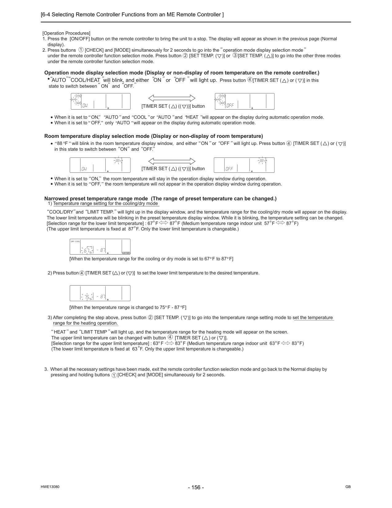
[6-4 Selecting Remote Controller Functions from an ME Remote Controller ]
Hwe13080
Gb
1Hr.Not Available
Ventilation
Stand By
Defrost
Timer
Check
[Operation Procedures]Centrally Controlled
Daily
Auto Off
Dry Cool
Auto Fan
Heat
Remainder
Error Code
Clock
Set Temp.
Auto
On
Auto
Off
Fan
Speed
Check Mode
Filter
Sensaor
Inside
Test Run
Limit Temp.
1Hr.Not Available
Ventilation
Stand By
Defrost
Timer
Check
Centrally Controlled
Daily
Auto Off
Dry Cool
Auto Fan
Heat
Remainder
Error Code
Clock
Set Temp.
Auto
On
Auto
Off
Fan
Speed
Check Mode
Filter
Sensaor
Inside
Test Run
Limit Temp.
1Hr.Not Available
Ventilation
Stand By
Defrost
Timer
Check
Centrally Controlled
Daily
Auto Off
Dry Cool
Auto Fan
Heat
Remainder
Error Code
Clock
Set Temp.
Auto
On
Auto
Off
Fan
Speed
Check Mode
Filter
Sensaor
Inside
Test Run
Limit Temp.
1Hr.Not Available
Ventilation
Stand By
Defrost
Timer
Check
Centrally Controlled
Daily
Auto Off
Dry Cool
Auto Fan
Heat
Remainder
Error Code
Clock
Set Temp.
Auto
On
Auto
Off
Fan
Speed
Check Mode
Filter
Sensaor
Inside
Test Run
Limit Temp.
1Hr.Not Available
Ventilation
Stand By
Defrost
Timer
Check
Centrally Controlled
Daily
Auto Off
Dry Cool
Auto Fan
Heat
Remainder
Error Code
Clock
Set Temp.
Auto
On
Auto
Off
Fan
Speed
Check Mode
Filter
Sensaor
Inside
Test Run
Limit Temp.
1Hr.Not Available
Ventilation
Stand By
Defrost
Timer
Check
[TIMER SET ( ) (( ))] button [TIMER SET ( ) (( ))] button 4 4 4 4 2 1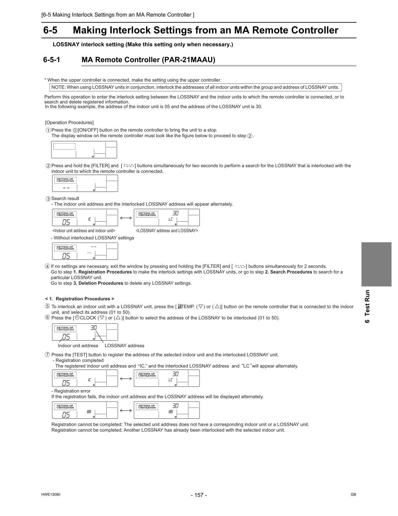
[6-5 Making Interlock Settings from an MA Remote Controller ]
Hwe13080
Gb
6 Test Run 6-5 Making Interlock Settings from an MA Remote Controller LOSSNAY interlock setting (Make this setting only when necessary.) 6-5-1 MA Remote Controller (PAR-21MAAU) [Operation Procedures]Press and hold the [FILTER] and [ ] buttons simultaneously for two seconds to perform a search for the LOSSNAY that is interlocked with the indoor unit to which the remote controller is connected. If no settings are necessary, exit the window by pressing and holding the [FILTER] and [ ] buttons simultaneously for 2 seconds. Go to step 1. Registration Procedures to make the interlock settings with LOSSNAY units, or go to step 2. Search Procedures to search for a particular LOSSNAY unit. Go to step 3. Deletion Procedures to delete any LOSSNAY settings. To interlock an indoor unit with a LOSSNAY unit, press the [ TEMP. ( ) or ( )] button on the remote controller that is connected to the indoor unit, and select its address (01 to 50). Press the [ CLOCK ( ) or ( )] button to select the address of the LOSSNAY to be interlocked (01 to 50). 5 4 7 6
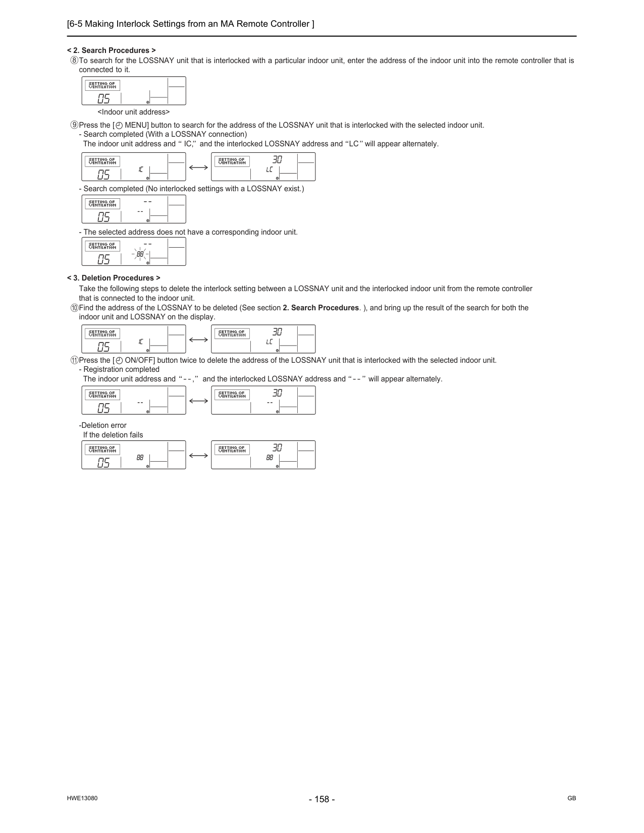
[6-5 Making Interlock Settings from an MA Remote Controller ]
Hwe13080
Gb
[6-6 Changing the Room Temperature Detection Position ]
Hwe13080
Gb
6 Test Run 6-6 Changing the Room Temperature Detection Position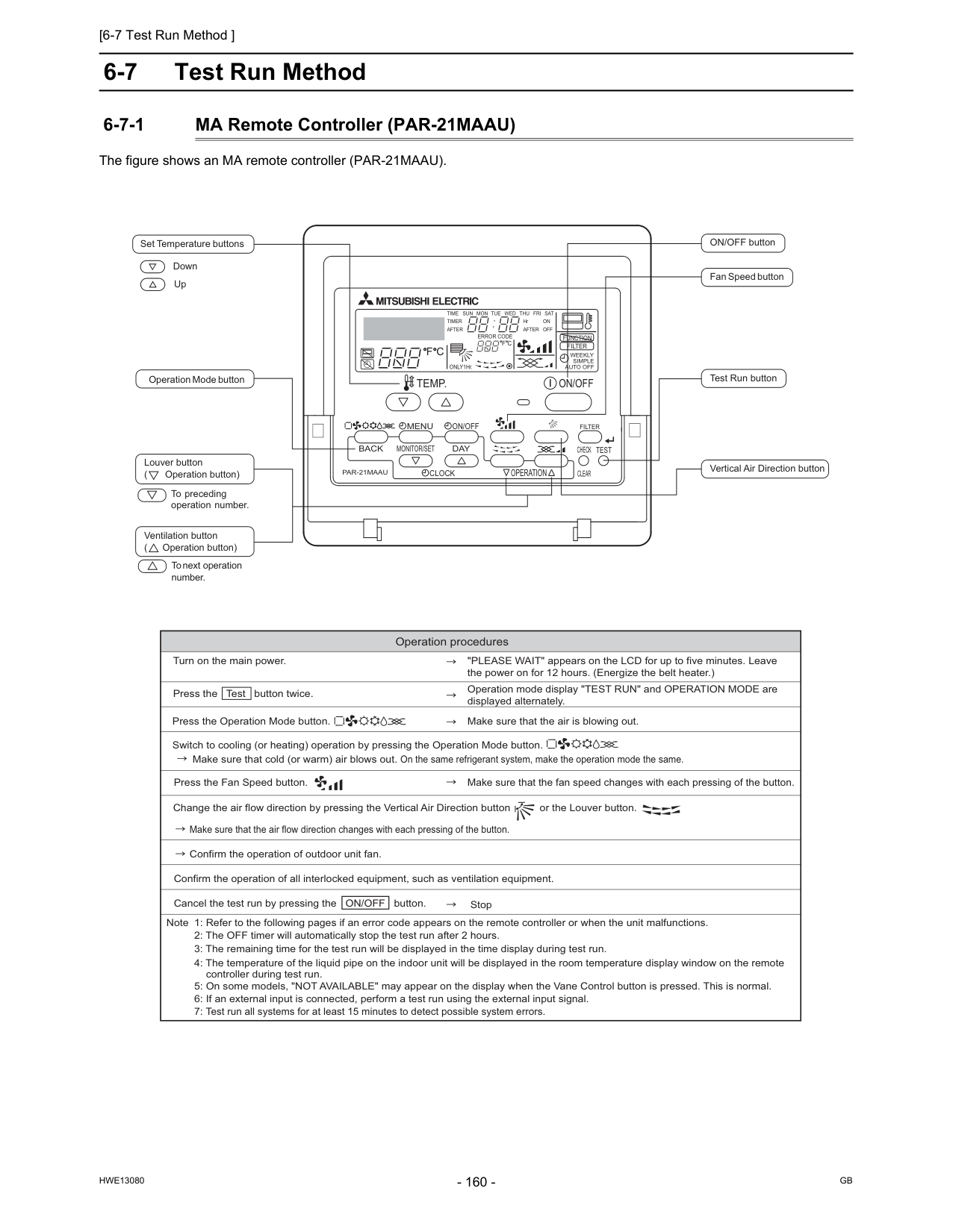
[6-7 Test Run Method ]
Hwe13080
Gb
6-7 Test Run Method 6-7-1 MA Remote Controller (PAR-21MAAU) The figure shows an MA remote controller (PAR-21MAAU).Par-21Maau
On/Off
Filter
Check
Operation
Clear
Test
Temp.
Menu
Back
Day
Monitor/Set
Clock
On/Off
Set Temperature buttons Down Up Operation Mode button ON/OFF button Fan Speed button Test Run button Vertical Air Direction button Louver button ( Operation button) To preceding operation number. Ventilation button ( Operation button) To next operation number.F C
F C
Error Code
After
Timer
Time Sun Mon Tue Wed Thu Fri Sat
On
Off
HrAfter
Filter
Function
ONLY1Hr.Weekly
Simple
Auto Off
Operation procedures Turn on the main power. "PLEASE WAIT" appears on the LCD for up to five minutes. Leave the power on for 12 hours. (Energize the belt heater.) Press the Test button twice. Operation mode display "TEST RUN" and OPERATION MODE are displayed alternately. Press the Operation Mode button. Make sure that cold (or warm) air blows out. On the same refrigerant system, make the operation mode the same. Make sure that the air is blowing out. Switch to cooling (or heating) operation by pressing the Operation Mode button. Press the Fan Speed button. Change the air flow direction by pressing the Vertical Air Direction button or the Louver button. Confirm the operation of outdoor unit fan. Confirm the operation of all interlocked equipment, such as ventilation equipment. Note 1: Refer to the following pages if an error code appears on the remote controller or when the unit malfunctions. 2: The OFF timer will automatically stop the test run after 2 hours. 3: The remaining time for the test run will be displayed in the time display during test run. 4: The temperature of the liquid pipe on the indoor unit will be displayed in the room temperature display window on the remote controller during test run. 5: On some models, "NOT AVAILABLE" may appear on the display when the Vane Control button is pressed. This is normal. 6: If an external input is connected, perform a test run using the external input signal. 7: Test run all systems for at least 15 minutes to detect possible system errors. Make sure that the fan speed changes with each pressing of the button. Stop Make sure that the air flow direction changes with each pressing of the button. Cancel the test run by pressing the ON/OFF button.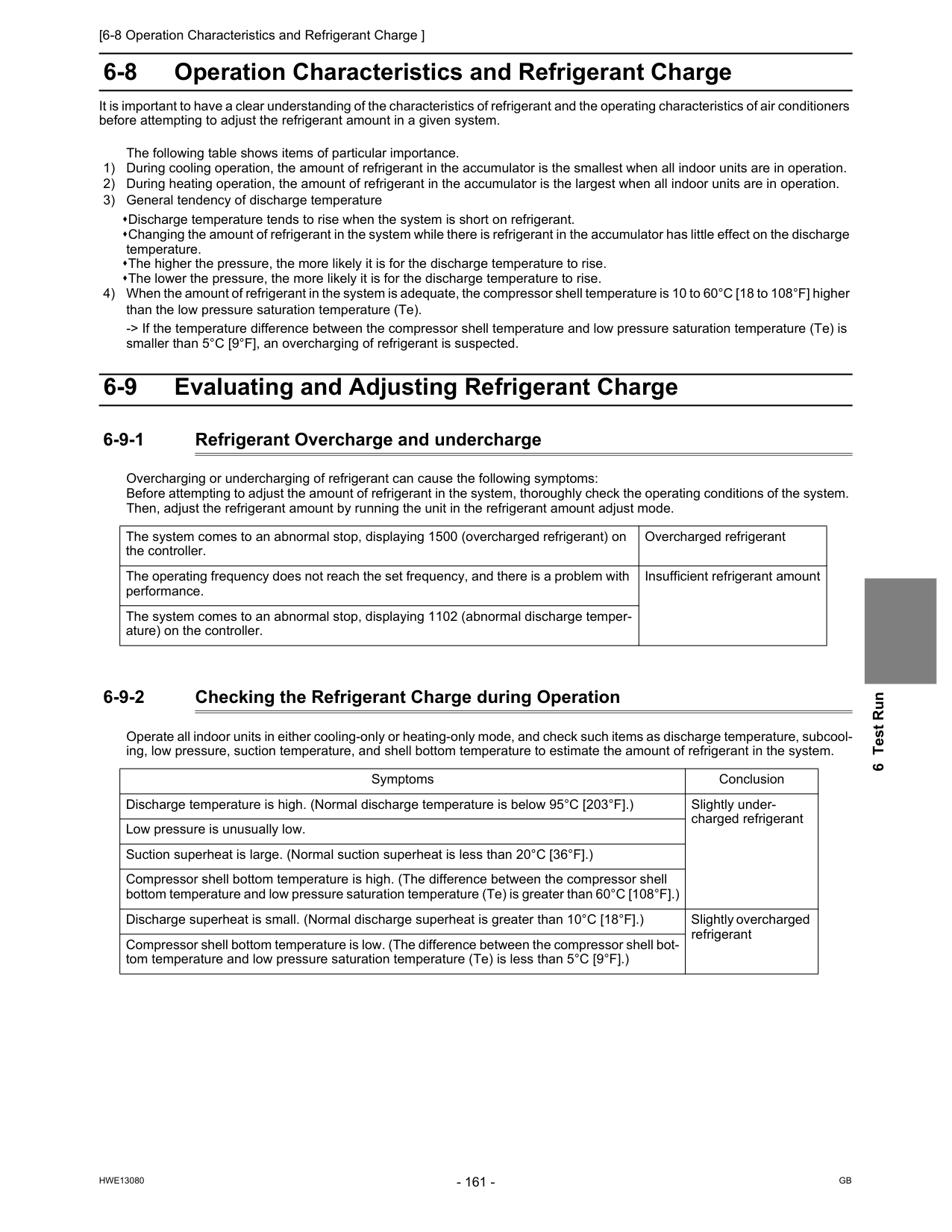
[6-8 Operation Characteristics and Refrigerant Charge ]
Hwe13080
Gb
6 Test Run 6-8 Operation Characteristics and Refrigerant Charge It is important to have a clear understanding of the characteristics of refrigerant and the operating characteristics of air conditioners before attempting to adjust the refrigerant amount in a given system. The following table shows items of particular importance. 1) During cooling operation, the amount of refrigerant in the accumulator is the smallest when all indoor units are in operation. 2) During heating operation, the amount of refrigerant in the accumulator is the largest when all indoor units are in operation. 3) General tendency of discharge temperature Discharge temperature tends to rise when the system is short on refrigerant. Changing the amount of refrigerant in the system while there is refrigerant in the accumulator has little effect on the discharge temperature. The higher the pressure, the more likely it is for the discharge temperature to rise. The lower the pressure, the more likely it is for the discharge temperature to rise. 4) When the amount of refrigerant in the system is adequate, the compressor shell temperature is 10 to 60°C [18 to 108°F] higher than the low pressure saturation temperature (Te). -> If the temperature difference between the compressor shell temperature and low pressure saturation temperature (Te) is smaller than 5°C [9°F], an overcharging of refrigerant is suspected. 6-9 Evaluating and Adjusting Refrigerant Charge 6-9-1 Refrigerant Overcharge and undercharge Overcharging or undercharging of refrigerant can cause the following symptoms: Before attempting to adjust the amount of refrigerant in the system, thoroughly check the operating conditions of the system. Then, adjust the refrigerant amount by running the unit in the refrigerant amount adjust mode. 6-9-2 Checking the Refrigerant Charge during Operation Operate all indoor units in either cooling-only or heating-only mode, and check such items as discharge temperature, subcool- ing, low pressure, suction temperature, and shell bottom temperature to estimate the amount of refrigerant in the system. The system comes to an abnormal stop, displaying 1500 (overcharged refrigerant) on the controller. Overcharged refrigerant The operating frequency does not reach the set frequency, and there is a problem with performance. Insufficient refrigerant amount The system comes to an abnormal stop, displaying 1102 (abnormal discharge temper- ature) on the controller. Symptoms Conclusion Discharge temperature is high. (Normal discharge temperature is below 95°C [203°F].) Slightly under- charged refrigerant Low pressure is unusually low. Suction superheat is large. (Normal suction superheat is less than 20°C [36°F].) Compressor shell bottom temperature is high. (The difference between the compressor shell bottom temperature and low pressure saturation temperature (Te) is greater than 60°C [108°F].) Discharge superheat is small. (Normal discharge superheat is greater than 10°C [18°F].) Slightly overcharged refrigerant Compressor shell bottom temperature is low. (The difference between the compressor shell bot- tom temperature and low pressure saturation temperature (Te) is less than 5°C [9°F].)
[6-9 Evaluating and Adjusting Refrigerant Charge ]
Hwe13080
Gb
6-9-3 The Amount of Refrigerant to Be Added The amount of refrigerant that is shown in the table below is factory-charged to the outdoor units. The amount necessary for extended pipe (field piping) is not included and must be added on site. (1) Calculation formula The amount of refrigerant to be added depends on the size and the length of field piping. (unit in m[ft]) Round up the calculation result to the nearest 0.1kg. (Example: 18.04kg to 18.1kg) Round up the calculation result in increments of 4oz (0.1kg) or round it up to the nearest 1oz. (Example: 78.21oz to 79oz) Outdoor unit modelHp72
Hp96
Amount of pre-charged refrigerant in the outdoor unit (kg) 11.8 11.8 Amount of pre-charged refrigerant in the outdoor unit [lbs-oz] 26-1 26-1 1) When the piping length from outdoor unit to the farthest indoor unit is 30.5 m [100 ft] or shorter Amount of added refrigerant (kg) = (0.23 x L1) + (0.16 x L2) + (0.11 x L3)+ (0.2 x L4) + (0.12 x L5) + (0.06 x L6) + (0.024 x L7) + α1 + α2 +α3 +α4+β Amount of added refrigerant (oz) = (2.48x L1' ) + (1.73 x L2' ) + (1.19x L3' )+ (2.16 x L4' ) + (1.30 x L5' ) + (0.65 x L6' ) + (0.26 x L7' ) + α1' + α2'+ α3 ' +α4'+β' 2) When the piping length from outdoor unit to the farthest indoor unit is longer than 30.5 m [100 ft] Amount of added refrigerant (kg) = (0.21 x L1) + (0.14 x L2) + (0.1 x L3)+ (0.18 x L4) + (0.11 x L5) + (0.054 x L6) + (0.021 x L7) + α1 + α2 +α3 +α4+β Amount of added refrigerant (oz) = (2.26x L1' ) + (1.51 x L2' ) + (1.08x L3' )+ (1.94 x L4' ) + (1.19 x L5' ) + (0.59 x L6' ) + (0.23 x L7' ) + α1' + α2'+ α3 ' +α4'+β' L1 : Length of ø22.2[7/8"] high pressure pipe (m) L2 : Length of ø19.05[3/4"] high pressure pipe (m) L3 : Length of ø15.88[5/8"] high pressure pipe (m) L4 : Length of ø15.88[5/8"] liquid pipe (m) L5 : Length of ø12.7[1/2"] liquid pipe (m) L6 : Length of ø9.52[3/8"] liquid pipe (m) L7 : Length of ø6.35[1/4"] liquid pipe (m) α1, α2, α3, α4, α1' , α2' , α3' , α4' : Refer to the table below. L1' : Length of ø22.2[7/8"] high pressure pipe [ft] L2' : Length of ø19.05[3/4"] high pressure pipe [ft] L3' : Length of ø15.88[5/8"] high pressure pipe [ft] L4' : Length of ø15.88[5/8"] liquid pipe [ft] L5' : Length of ø12.7[1/2"] liquid pipe [ft] L6' : Length of ø9.52[3/8"] liquid pipe [ft] L7' : Length of ø6.35[1/4"] liquid pipe [ft] β, β' : Refer to the table below. Outdoor unit total index Amount for the BC con- trollers (standard/main) BC controller (main) Total capacity of connected indoor units Amount for the Indoor unit α1(kg) α1' (oz) α4(kg) α4' (oz) HP72 model 3.0 106 HA type α2(kg) α2' (oz)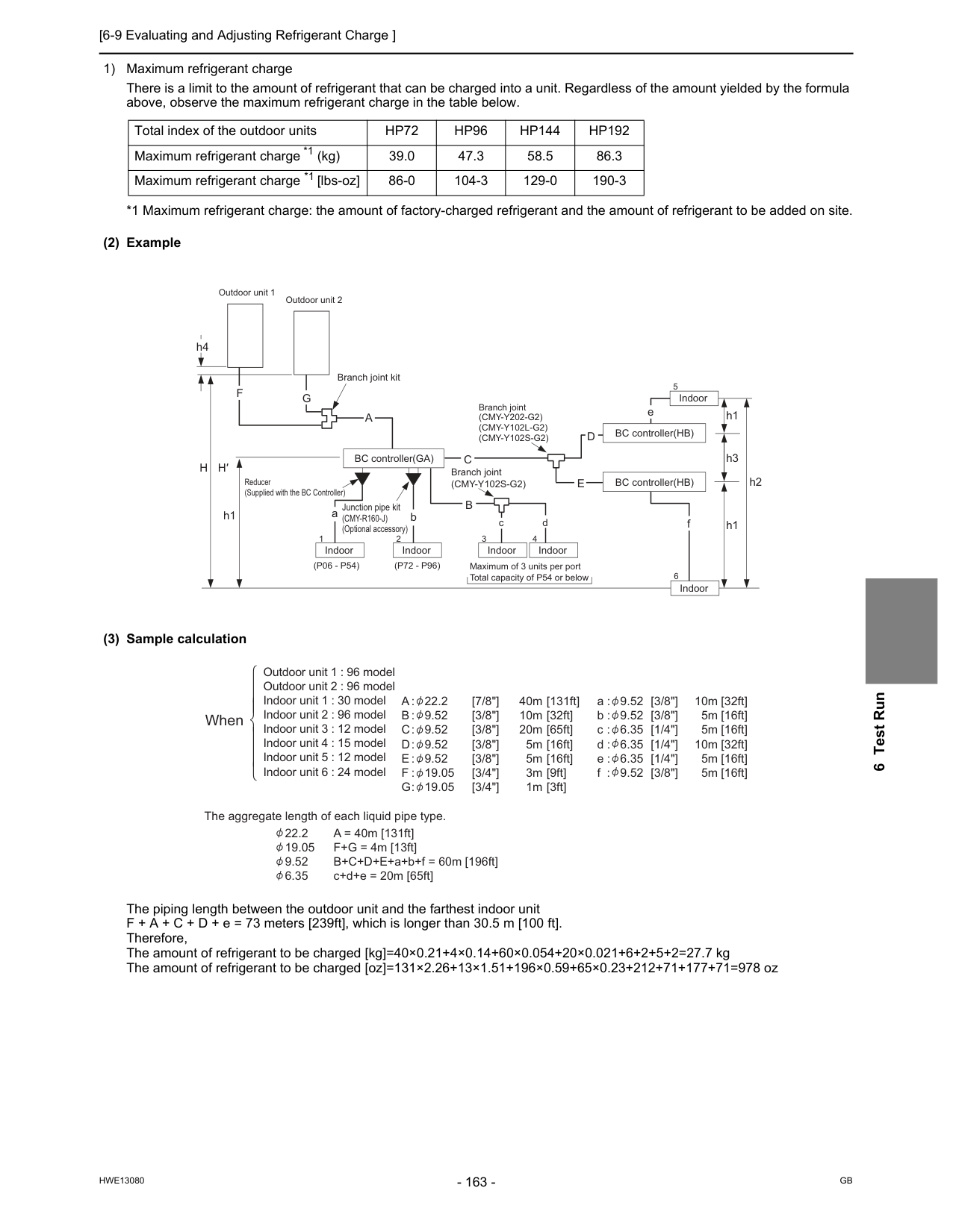
[6-9 Evaluating and Adjusting Refrigerant Charge ]
Hwe13080
Gb
6 Test Run 1) Maximum refrigerant charge There is a limit to the amount of refrigerant that can be charged into a unit. Regardless of the amount yielded by the formula above, observe the maximum refrigerant charge in the table below. *1 Maximum refrigerant charge: the amount of factory-charged refrigerant and the amount of refrigerant to be added on site. (2) Example (3) Sample calculation The piping length between the outdoor unit and the farthest indoor unit F + A + C + D + e = 73 meters [239ft], which is longer than 30.5 m [100 ft]. Therefore, The amount of refrigerant to be charged [kg]=40×0.21+4×0.14+60×0.054+20×0.021+6+2+5+2=27.7 kg The amount of refrigerant to be charged [oz]=131×2.26+13×1.51+196×0.59+65×0.23+212+71+177+71=978 oz Total index of the outdoor unitsHp72
Hp96
Hp144
Hp192
Maximum refrigerant charge *1 (kg) 39.0 47.3 58.5 86.3 Maximum refrigerant charge *1 [lbs-oz] 86-0 104-3 129-0 190-3 BC controller(GA) BC controller(HB) BC controller(HB) Indoor aC
bH
H′
h1 h1(P06 - P54)
Junction pipe kit(Cmy-R160-J)
(Optional accessory) Branch joint(Cmy-Y102S-G2)
B
c d f h3D
E
Branch joint(Cmy-Y202-G2)
(Cmy-Y102L-G2)
(Cmy-Y102S-G2)
A
e h1F
h4 Branch joint kit Outdoor unit 1 Outdoor unit 2 Reducer (Supplied with the BC Controller)G
h2 Indoor Indoor Maximum of 3 units per port Total capacity of P54 or below Indoor Indoor Indoor 2 6 5 3 4 1(P72 - P96)
Outdoor unit 1 : 96 model Outdoor unit 2 : 96 model Indoor unit 1 : 30 model Indoor unit 2 : 96 model Indoor unit 3 : 12 model Indoor unit 4 : 15 model Indoor unit 5 : 12 model Indoor unit 6 : 24 modelA : 22.2
B : 9.52
C : 9.52
D : 9.52
E : 9.52
F : 19.05
G : 19.05
40m 10m 20m 5m 5m 3m 1m [7/8"] [3/8"] [3/8"] [3/8"] [3/8"] [3/4"] [3/4"] [3/8"] [3/8"] [1/4"] [1/4"] [1/4"] [3/8"] [131ft] [32ft] [65ft] [16ft] [16ft] [9ft] [3ft] [32ft] [16ft] [16ft] [32ft] [16ft] [16ft] a : 9.52 b : 9.52 c : 6.35 d : 6.35 e : 6.35 f : 9.52 10m 5m 5m 10m 5m 5m 22.2 A = 40m [131ft] 19.05 F+G = 4m [13ft] 9.52 B+C+D+E+a+b+f = 60m [196ft] 6.35 c+d+e = 20m [65ft] The aggregate length of each liquid pipe type. When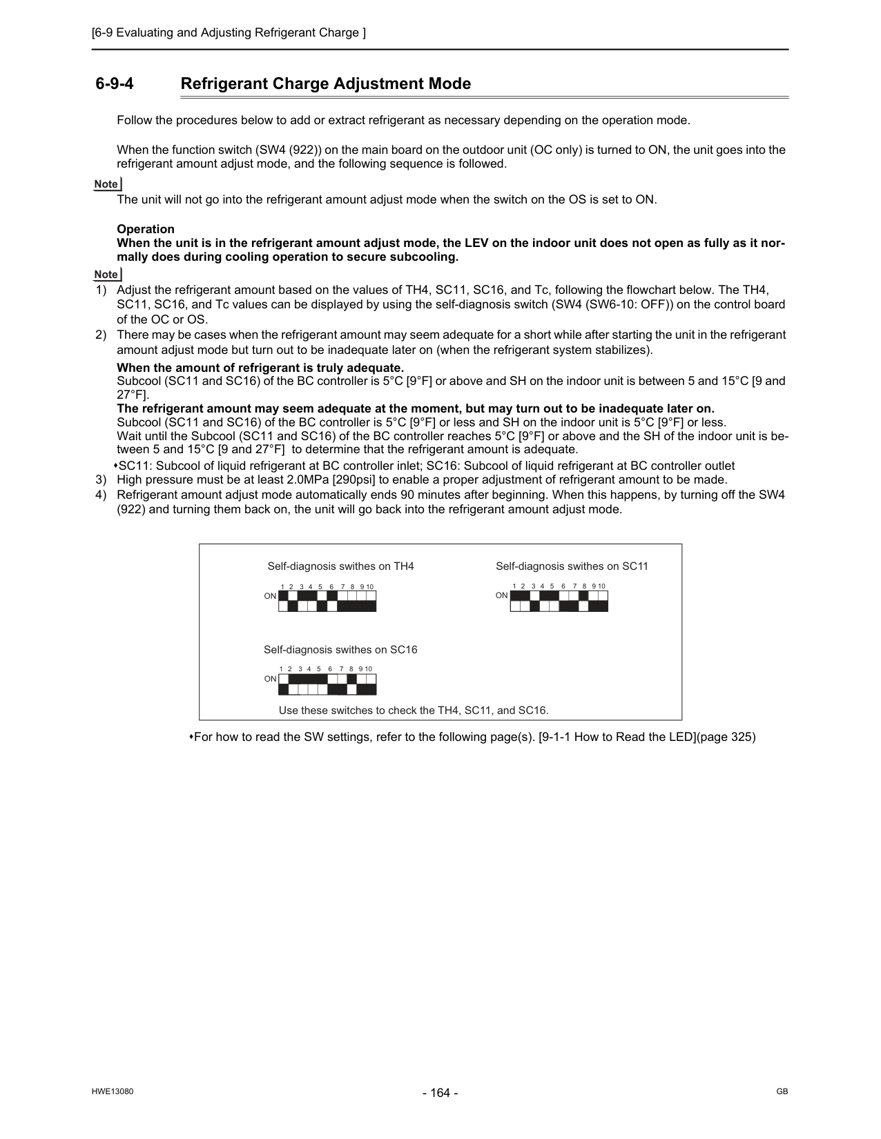
[6-9 Evaluating and Adjusting Refrigerant Charge ]
Hwe13080
Gb
6-9-4 Refrigerant Charge Adjustment Mode Follow the procedures below to add or extract refrigerant as necessary depending on the operation mode. When the function switch (SW4 (922)) on the main board on the outdoor unit (OC only) is turned to ON, the unit goes into the refrigerant amount adjust mode, and the following sequence is followed. The unit will not go into the refrigerant amount adjust mode when the switch on the OS is set to ON. Operation When the unit is in the refrigerant amount adjust mode, the LEV on the indoor unit does not open as fully as it nor- mally does during cooling operation to secure subcooling. 1) Adjust the refrigerant amount based on the values of TH4, SC11, SC16, and Tc, following the flowchart below. The TH4, SC11, SC16, and Tc values can be displayed by using the self-diagnosis switch (SW4 (SW6-10: OFF)) on the control board of the OC or OS. 2) There may be cases when the refrigerant amount may seem adequate for a short while after starting the unit in the refrigerant amount adjust mode but turn out to be inadequate later on (when the refrigerant system stabilizes). When the amount of refrigerant is truly adequate. Subcool (SC11 and SC16) of the BC controller is 5°C [9°F] or above and SH on the indoor unit is between 5 and 15°C [9 and27°F].
The refrigerant amount may seem adequate at the moment, but may turn out to be inadequate later on. Subcool (SC11 and SC16) of the BC controller is 5°C [9°F] or less and SH on the indoor unit is 5°C [9°F] or less. Wait until the Subcool (SC11 and SC16) of the BC controller reaches 5°C [9°F] or above and the SH of the indoor unit is be- tween 5 and 15°C [9 and 27°F] to determine that the refrigerant amount is adequate. SC11: Subcool of liquid refrigerant at BC controller inlet; SC16: Subcool of liquid refrigerant at BC controller outlet 3) High pressure must be at least 2.0MPa [290psi] to enable a proper adjustment of refrigerant amount to be made. 4) Refrigerant amount adjust mode automatically ends 90 minutes after beginning. When this happens, by turning off the SW4 (922) and turning them back on, the unit will go back into the refrigerant amount adjust mode. For how to read the SW settings, refer to the following page(s). [9-1-1 How to Read the LED](page 325) Self-diagnosis swithes on TH4 Self-diagnosis swithes on SC16 Use these switches to check the TH4, SC11, and SC16. Self-diagnosis swithes on SC11On
On
1 2 3 4 5 6 7 8 9 10 1 2 3 4 5 6 7 8 9 10 1 2 3 4 5 6 7 8 9 10On
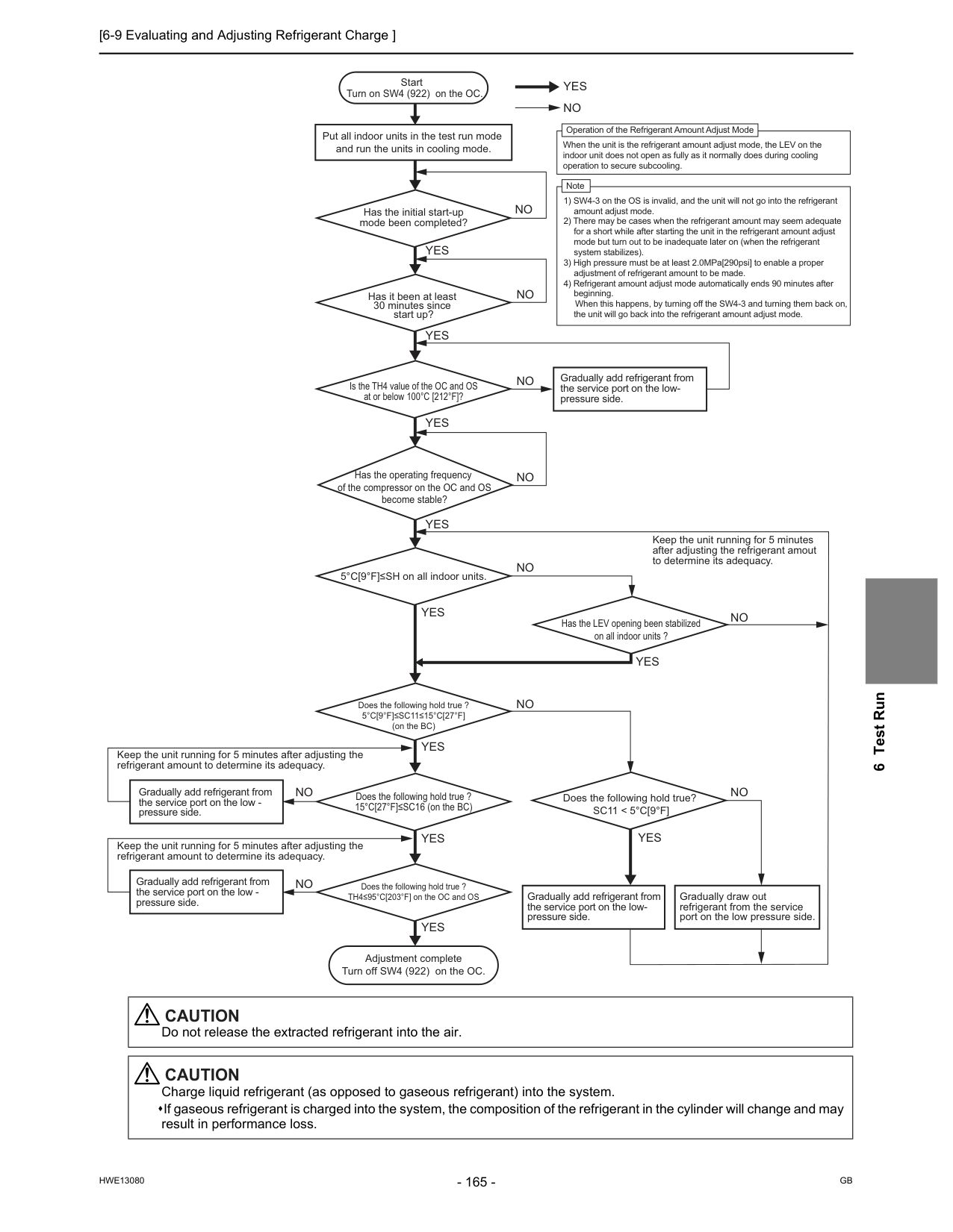
[6-9 Evaluating and Adjusting Refrigerant Charge ]
Hwe13080
Gb
6 Test RunYes
Yes
Yes
Yes
Yes
Yes
Yes
Yes
Yes
Yes
No
No
No
No
No
No
No
No
No
Start Put all indoor units in the test run mode and run the units in cooling mode. Has it been at least 30 minutes since start up? 5°C[9°F]≤SH on all indoor units. Has the LEV opening been stabilized on all indoor units ?No
Does the following hold true?Sc11 < 5°C[9°F]
Yes
No
Does the following hold true ?5°C[9°F]≤Sc11≤15°C[27°F]
(on the BC) Gradually add refrigerant from the service port on the low- pressure side. Keep the unit running for 5 minutes after adjusting the refrigerant amount to determine its adequacy. Keep the unit running for 5 minutes after adjusting the refrigerant amount to determine its adequacy. Turn on SW4 (922) on the OC. Adjustment complete Turn off SW4 (922) on the OC. Has the initial start-up mode been completed? Gradually add refrigerant from the service port on the low - pressure side. Gradually add refrigerant from the service port on the low - pressure side. Keep the unit running for 5 minutes after adjusting the refrigerant amout to determine its adequacy. Gradually add refrigerant from the service port on the low- pressure side. Gradually draw out refrigerant from the service port on the low pressure side. Is the TH4 value of the OC and OS at or below 100°C [212°F]? Has the operating frequency of the compressor on the OC and OS become stable? Does the following hold true ? TH4≤95°C[203°F] on the OC and OS Does the following hold true ? 15°C[27°F]≤SC16 (on the BC) Operation of the Refrigerant Amount Adjust Mode When the unit is the refrigerant amount adjust mode, the LEV on the indoor unit does not open as fully as it normally does during cooling operation to secure subcooling. Note 1) SW4-3 on the OS is invalid, and the unit will not go into the refrigerant amount adjust mode. 2) There may be cases when the refrigerant amount may seem adequate for a short while after starting the unit in the refrigerant amount adjust mode but turn out to be inadequate later on (when the refrigerant system stabilizes). 3) High pressure must be at least 2.0MPa[290psi] to enable a proper adjustment of refrigerant amount to be made. 4) Refrigerant amount adjust mode automatically ends 90 minutes after beginning. When this happens, by turning off the SW4-3 and turning them back on, the unit will go back into the refrigerant amount adjust mode.Caution
Do not release the extracted refrigerant into the air.Caution
Charge liquid refrigerant (as opposed to gaseous refrigerant) into the system. If gaseous refrigerant is charged into the system, the composition of the refrigerant in the cylinder will change and may result in performance loss.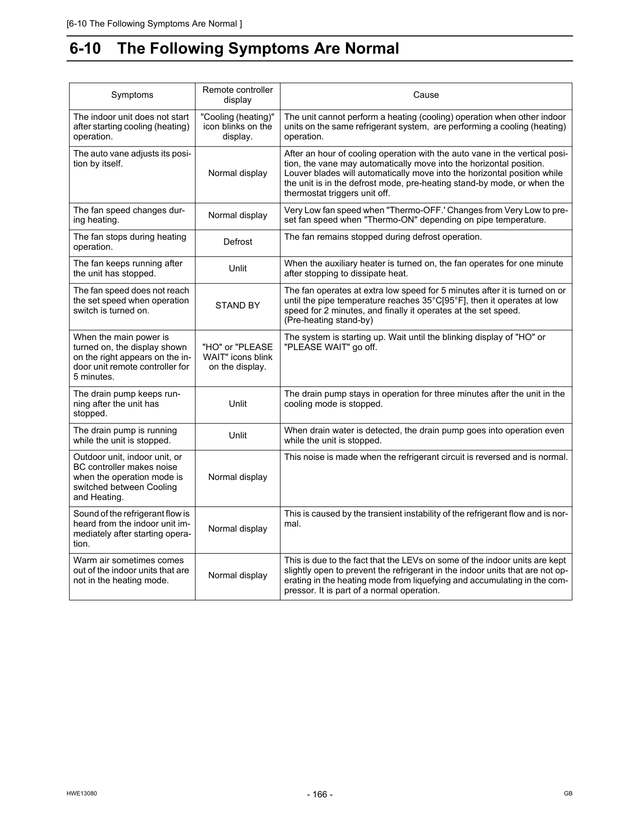
[6-10 The Following Symptoms Are Normal ]
Hwe13080
Gb
6-10 The Following Symptoms Are Normal Symptoms Remote controller display Cause The indoor unit does not start after starting cooling (heating) operation. "Cooling (heating)" icon blinks on the display. The unit cannot perform a heating (cooling) operation when other indoor units on the same refrigerant system, are performing a cooling (heating) operation. The auto vane adjusts its posi- tion by itself. Normal display After an hour of cooling operation with the auto vane in the vertical posi- tion, the vane may automatically move into the horizontal position. Louver blades will automatically move into the horizontal position while the unit is in the defrost mode, pre-heating stand-by mode, or when the thermostat triggers unit off. The fan speed changes dur- ing heating. Normal display Very Low fan speed when "Thermo-OFF.' Changes from Very Low to pre- set fan speed when "Thermo-ON" depending on pipe temperature. The fan stops during heating operation. Defrost The fan remains stopped during defrost operation. The fan keeps running after the unit has stopped. Unlit When the auxiliary heater is turned on, the fan operates for one minute after stopping to dissipate heat. The fan speed does not reach the set speed when operation switch is turned on.Stand By
The fan operates at extra low speed for 5 minutes after it is turned on or until the pipe temperature reaches 35°C[95°F], then it operates at low speed for 2 minutes, and finally it operates at the set speed. (Pre-heating stand-by) When the main power is turned on, the display shown on the right appears on the in- door unit remote controller for 5 minutes. "HO" or "PLEASE WAIT" icons blink on the display. The system is starting up. Wait until the blinking display of "HO" or "PLEASE WAIT" go off. The drain pump keeps run- ning after the unit has stopped. Unlit The drain pump stays in operation for three minutes after the unit in the cooling mode is stopped. The drain pump is running while the unit is stopped. Unlit When drain water is detected, the drain pump goes into operation even while the unit is stopped. Outdoor unit, indoor unit, or BC controller makes noise when the operation mode is switched between Cooling and Heating. Normal display This noise is made when the refrigerant circuit is reversed and is normal. Sound of the refrigerant flow is heard from the indoor unit im- mediately after starting opera- tion. Normal display This is caused by the transient instability of the refrigerant flow and is nor- mal. Warm air sometimes comes out of the indoor units that are not in the heating mode. Normal display This is due to the fact that the LEVs on some of the indoor units are kept slightly open to prevent the refrigerant in the indoor units that are not op- erating in the heating mode from liquefying and accumulating in the com- pressor. It is part of a normal operation.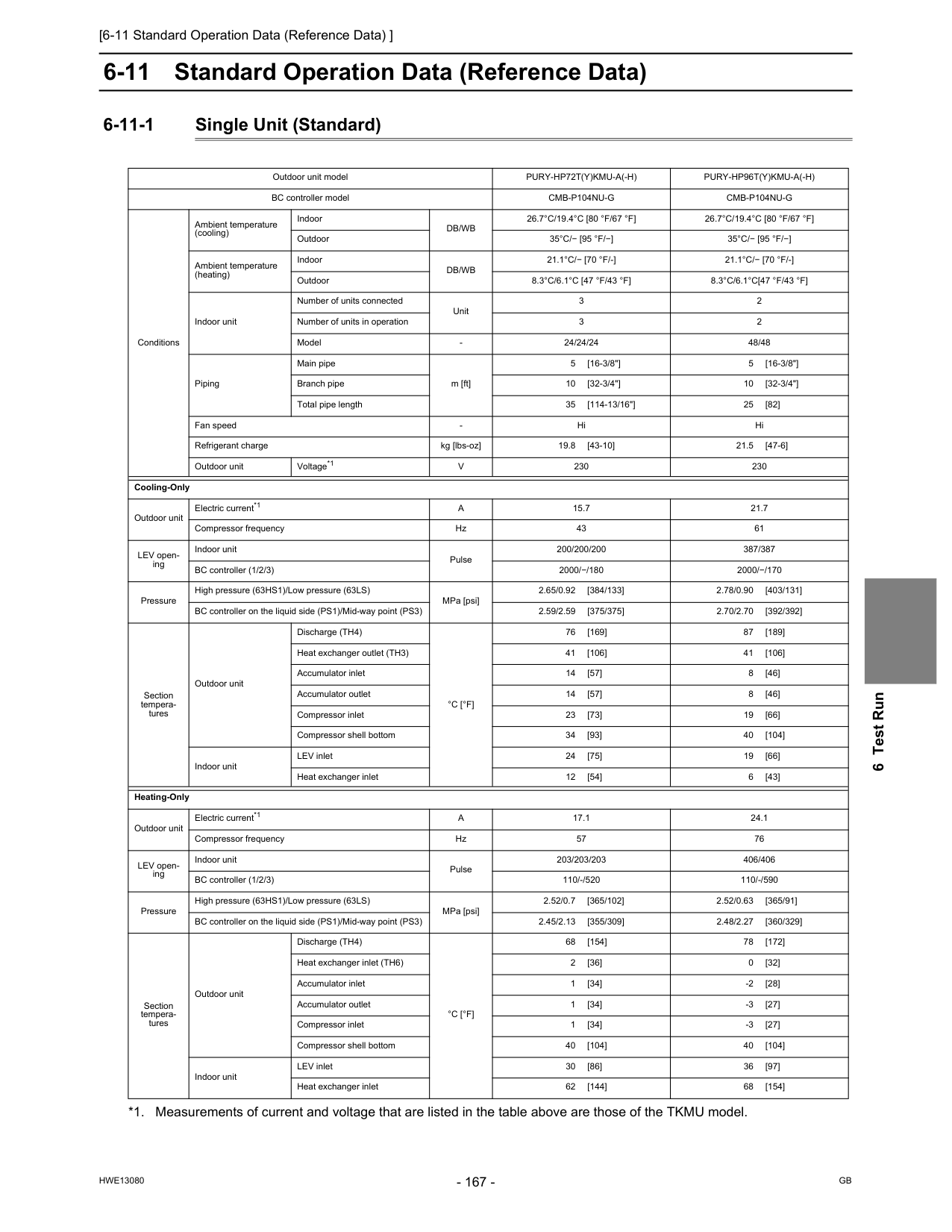
[6-11 Standard Operation Data (Reference Data) ]
Hwe13080
Gb
6 Test Run 6-11 Standard Operation Data (Reference Data) 6-11-1 Single Unit (Standard) Outdoor unit modelPury-Hp72T(Y)Kmu-A(-H)
Pury-Hp96T(Y)Kmu-A(-H)
BC controller modelCmb-P104Nu-G
Cmb-P104Nu-G
Conditions Ambient temperature (cooling) IndoorDb/Wb
26.7°C/19.4°C [80 °F/67 °F]
26.7°C/19.4°C [80 °F/67 °F]
Outdoor35°C/− [95 °F/−]
35°C/− [95 °F/−]
Ambient temperature (heating) IndoorDb/Wb
21.1°C/− [70 °F/-]
21.1°C/− [70 °F/-]
Outdoor8.3°C/6.1°C [47 °F/43 °F]
8.3°C/6.1°C[47 °F/43 °F]
Indoor unit Number of units connected Unit 3 2 Number of units in operation 3 2 ModelV
230 230 Cooling-Only Outdoor unit Electric current*1A
15.7 21.7 Compressor frequency Hz 43 61 LEV open- ing Indoor unit Pulse 200/200/200 387/387 BC controller (1/2/3) 2000/−/180 2000/−/170 Pressure High pressure (63HS1)/Low pressure (63LS) MPa [psi] 2.65/0.92 [384/133] 2.78/0.90 [403/131] BC controller on the liquid side (PS1)/Mid-way point (PS3) 2.59/2.59 [375/375] 2.70/2.70 [392/392] Section tempera- tures Outdoor unit Discharge (TH4)°C [°F]
76 [169] 87 [189] Heat exchanger outlet (TH3) 41 [106] 41 [106] Accumulator inlet 14 [57] 8 [46] Accumulator outlet 14 [57] 8 [46] Compressor inlet 23 [73] 19 [66] Compressor shell bottom 34 [93] 40 [104] Indoor unit LEV inlet 24 [75] 19 [66] Heat exchanger inlet 12 [54] 6 [43] Heating-Only Outdoor unit Electric current*1A
17.1 24.1 Compressor frequency Hz 57 76 LEV open- ing Indoor unit Pulse 203/203/203 406/406 BC controller (1/2/3) 110/-/520 110/-/590 Pressure High pressure (63HS1)/Low pressure (63LS) MPa [psi] 2.52/0.7 [365/102] 2.52/0.63 [365/91] BC controller on the liquid side (PS1)/Mid-way point (PS3) 2.45/2.13 [355/309] 2.48/2.27 [360/329] Section tempera- tures Outdoor unit Discharge (TH4)°C [°F]
68 [154] 78 [172] Heat exchanger inlet (TH6) 2 [36] 0 [32] Accumulator inlet 1 [34] -2 [28] Accumulator outlet 1 [34] -3 [27] Compressor inlet 1 [34] -3 [27] Compressor shell bottom 40 [104] 40 [104] Indoor unit LEV inlet 30 [86] 36 [97] Heat exchanger inlet 62 [144] 68 [154]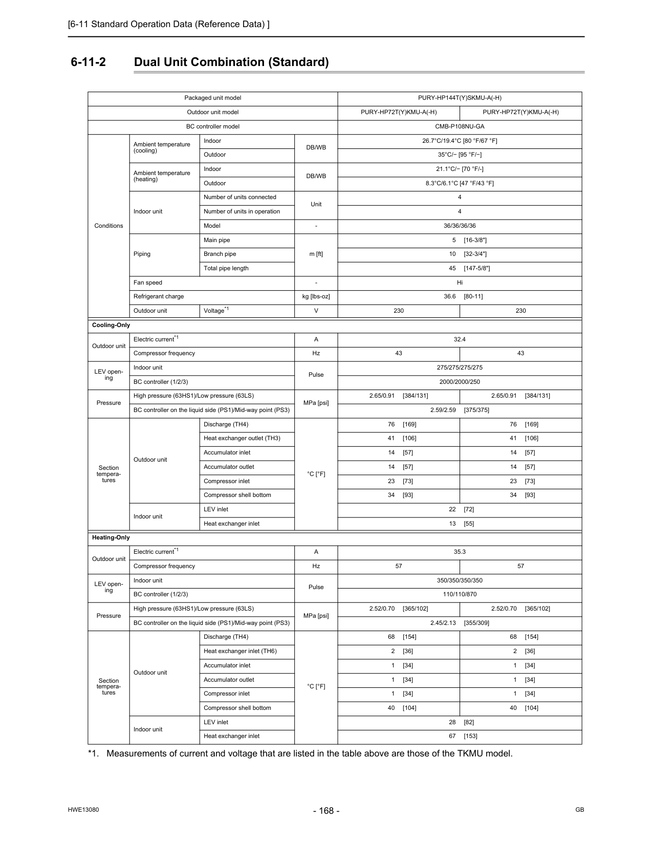
[6-11 Standard Operation Data (Reference Data) ]
Hwe13080
Gb
6-11-2 Dual Unit Combination (Standard) Packaged unit modelPury-Hp144T(Y)Skmu-A(-H)
Outdoor unit modelPury-Hp72T(Y)Kmu-A(-H)
Pury-Hp72T(Y)Kmu-A(-H)
BC controller modelCmb-P108Nu-Ga
Conditions Ambient temperature (cooling) IndoorDb/Wb
26.7°C/19.4°C [80 °F/67 °F]
Outdoor35°C/− [95 °F/−]
Ambient temperature (heating) IndoorDb/Wb
21.1°C/− [70 °F/-]
Outdoor8.3°C/6.1°C [47 °F/43 °F]
Indoor unit Number of units connected Unit 4 Number of units in operation 4 ModelV
230 230 Cooling-Only Outdoor unit Electric current*1A
32.4 Compressor frequency Hz 43 43 LEV open- ing Indoor unit Pulse 275/275/275/275 BC controller (1/2/3) 2000/2000/250 Pressure High pressure (63HS1)/Low pressure (63LS) MPa [psi] 2.65/0.91 [384/131] 2.65/0.91 [384/131] BC controller on the liquid side (PS1)/Mid-way point (PS3) 2.59/2.59 [375/375] Section tempera- tures Outdoor unit Discharge (TH4)°C [°F]
76 [169] 76 [169] Heat exchanger outlet (TH3) 41 [106] 41 [106] Accumulator inlet 14 [57] 14 [57] Accumulator outlet 14 [57] 14 [57] Compressor inlet 23 [73] 23 [73] Compressor shell bottom 34 [93] 34 [93] Indoor unit LEV inlet 22 [72] Heat exchanger inlet 13 [55] Heating-Only Outdoor unit Electric current*1A
35.3 Compressor frequency Hz 57 57 LEV open- ing Indoor unit Pulse 350/350/350/350 BC controller (1/2/3) 110/110/870 Pressure High pressure (63HS1)/Low pressure (63LS) MPa [psi] 2.52/0.70 [365/102] 2.52/0.70 [365/102] BC controller on the liquid side (PS1)/Mid-way point (PS3) 2.45/2.13 [355/309] Section tempera- tures Outdoor unit Discharge (TH4)°C [°F]
68 [154] 68 [154] Heat exchanger inlet (TH6) 2 [36] 2 [36] Accumulator inlet 1 [34] 1 [34] Accumulator outlet 1 [34] 1 [34] Compressor inlet 1 [34] 1 [34] Compressor shell bottom 40 [104] 40 [104] Indoor unit LEV inlet 28 [82] Heat exchanger inlet 67 [153]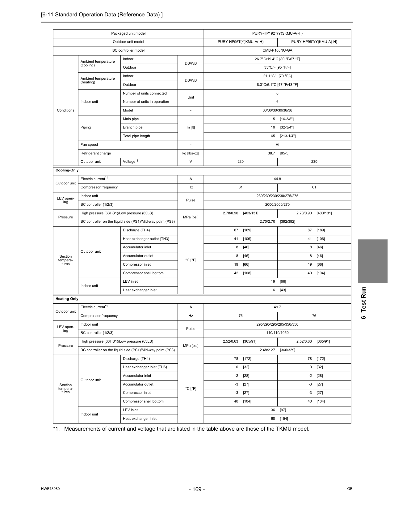
[6-11 Standard Operation Data (Reference Data) ]
Hwe13080
Gb
6 Test Run Packaged unit modelPury-Hp192T(Y)Skmu-A(-H)
Outdoor unit modelPury-Hp96T(Y)Kmu-A(-H)
Pury-Hp96T(Y)Kmu-A(-H)
BC controller modelCmb-P108Nu-Ga
Conditions Ambient temperature (cooling) IndoorDb/Wb
26.7°C/19.4°C [80 °F/67 °F]
Outdoor35°C/− [95 °F/−]
Ambient temperature (heating) IndoorDb/Wb
21.1°C/− [70 °F/-]
Outdoor8.3°C/6.1°C [47 °F/43 °F]
Indoor unit Number of units connected Unit 6 Number of units in operation 6 ModelV
230 230 Cooling-Only Outdoor unit Electric current*1A
44.8 Compressor frequency Hz 61 61 LEV open- ing Indoor unit Pulse 230/230/230/230/275/275 BC controller (1/2/3) 2000/2000/270 Pressure High pressure (63HS1)/Low pressure (63LS) MPa [psi] 2.78/0.90 [403/131] 2.78/0.90 [403/131] BC controller on the liquid side (PS1)/Mid-way point (PS3) 2.70/2.70 [392/392] Section tempera- tures Outdoor unit Discharge (TH4)°C [°F]
87 [189] 87 [189] Heat exchanger outlet (TH3) 41 [106] 41 [106] Accumulator inlet 8 [46] 8 [46] Accumulator outlet 8 [46] 8 [46] Compressor inlet 19 [66] 19 [66] Compressor shell bottom 42 [108] 40 [104] Indoor unit LEV inlet 19 [66] Heat exchanger inlet 6 [43] Heating-Only Outdoor unit Electric current*1A
49.7 Compressor frequency Hz 76 76 LEV open- ing Indoor unit Pulse 295/295/295/295/350/350 BC controller (1/2/3) 110/110/1050 Pressure High pressure (63HS1)/Low pressure (63LS) MPa [psi] 2.52/0.63 [365/91] 2.52/0.63 [365/91] BC controller on the liquid side (PS1)/Mid-way point (PS3) 2.48/2.27 [360/329] Section tempera- tures Outdoor unit Discharge (TH4)°C [°F]
78 [172] 78 [172] Heat exchanger inlet (TH6) 0 [32] 0 [32] Accumulator inlet -2 [28] -2 [28] Accumulator outlet -3 [27] -3 [27] Compressor inlet -3 [27] -3 [27] Compressor shell bottom 40 [104] 40 [104] Indoor unit LEV inlet 36 [97] Heat exchanger inlet 68 [154]
[6-11 Standard Operation Data (Reference Data) ]
Hwe13080
Gb
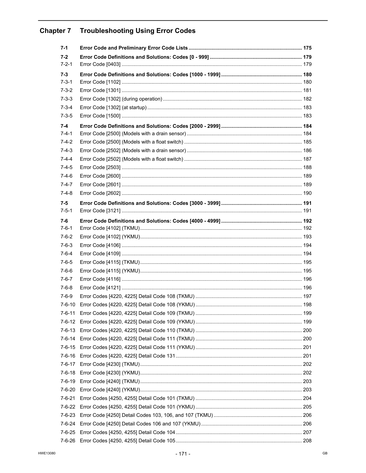
Hwe13080
Gb
Chapter 7 Troubleshooting Using Error Codes 7-1 Error Code and Preliminary Error Code Lists................................................................................ 175 7-2 Error Code Definitions and Solutions: Codes [0 - 999] ................................................................. 179 7-2-1 Error Code [0403] ............................................................................................................................... 179 7-3 Error Code Definitions and Solutions: Codes [1000 - 1999] ......................................................... 180 7-3-1 Error Code [1102] ............................................................................................................................... 180 7-3-2 Error Code [1301] ............................................................................................................................... 181 7-3-3 Error Code [1302] (during operation).................................................................................................. 182 7-3-4 Error Code [1302] (at startup)............................................................................................................. 183 7-3-5 Error Code [1500] ............................................................................................................................... 183 7-4 Error Code Definitions and Solutions: Codes [2000 - 2999] ......................................................... 184 7-4-1 Error Code [2500] (Models with a drain sensor) ................................................................................. 184 7-4-2 Error Code [2500] (Models with a float switch) ................................................................................... 185 7-4-3 Error Code [2502] (Models with a drain sensor) ................................................................................. 186 7-4-4 Error Code [2502] (Models with a float switch) ................................................................................... 187 7-4-5 Error Code [2503] ............................................................................................................................... 188 7-4-6 Error Code [2600] ............................................................................................................................... 189 7-4-7 Error Code [2601] ............................................................................................................................... 189 7-4-8 Error Code [2602] ............................................................................................................................... 190 7-5 Error Code Definitions and Solutions: Codes [3000 - 3999] ......................................................... 191 7-5-1 Error Code [3121] ............................................................................................................................... 191 7-6 Error Code Definitions and Solutions: Codes [4000 - 4999] ......................................................... 192 7-6-1 Error Code [4102] (TKMU).................................................................................................................. 192 7-6-2 Error Code [4102] (YKMU).................................................................................................................. 193 7-6-3 Error Code [4106] ............................................................................................................................... 194 7-6-4 Error Code [4109] ............................................................................................................................... 194 7-6-5 Error Code [4115] (TKMU).................................................................................................................. 195 7-6-6 Error Code [4115] (YKMU).................................................................................................................. 195 7-6-7 Error Code [4116] ............................................................................................................................... 196 7-6-8 Error Code [4121] ............................................................................................................................... 196 7-6-9 Error Codes [4220, 4225] Detail Code 108 (TKMU) ........................................................................... 197 7-6-10 Error Codes [4220, 4225] Detail Code 108 (YKMU)........................................................................... 198 7-6-11 Error Codes [4220, 4225] Detail Code 109 (TKMU) ........................................................................... 199 7-6-12 Error Codes [4220, 4225] Detail Code 109 (YKMU)........................................................................... 199 7-6-13 Error Codes [4220, 4225] Detail Code 110 (TKMU) ........................................................................... 200 7-6-14 Error Codes [4220, 4225] Detail Code 111 (TKMU) ........................................................................... 200 7-6-15 Error Codes [4220, 4225] Detail Code 111 (YKMU)........................................................................... 201 7-6-16 Error Codes [4220, 4225] Detail Code 131......................................................................................... 201 7-6-17 Error Code [4230] (TKMU).................................................................................................................. 202 7-6-18 Error Code [4230] (YKMU).................................................................................................................. 202 7-6-19 Error Code [4240] (TKMU).................................................................................................................. 203 7-6-20 Error Code [4240] (YKMU).................................................................................................................. 203 7-6-21 Error Codes [4250, 4255] Detail Code 101 (TKMU) ........................................................................... 204 7-6-22 Error Codes [4250, 4255] Detail Code 101 (YKMU)........................................................................... 205 7-6-23 Error Code [4250] Detail Codes 103, 106, and 107 (TKMU) .............................................................. 206 7-6-24 Error Code [4250] Detail Codes 106 and 107 (YKMU)....................................................................... 206 7-6-25 Error Codes [4250, 4255] Detail Code 104......................................................................................... 207 7-6-26 Error Codes [4250, 4255] Detail Code 105......................................................................................... 208
Hwe13080
Gb
7-6-27 Error Code [4260] (TKMU).................................................................................................................. 209 7-6-28 Error Code [4260] (YKMU).................................................................................................................. 209 7-7 Error Code Definitions and Solutions: Codes [5000 - 5999] ......................................................... 210 7-7-1 Error Codes [5101, 5102, 5103, 5104]................................................................................................ 210 7-7-2 Error Codes [5104, 5105, 5106, 5107, 5109, 5111]............................................................................ 211 7-7-3 Error Code [5110] (TKMU).................................................................................................................. 212 7-7-4 Error Code [5110] (YKMU).................................................................................................................. 212 7-7-5 Error Codes [5111, 5112, 5115, 5116]................................................................................................ 213 7-7-6 Error Code [5201] ............................................................................................................................... 214 7-7-7 Error Codes [5201, 5203].................................................................................................................... 214 7-7-8 Error Code [5301] Detail Code 115 (TKMU)....................................................................................... 215 7-7-9 Error Code [5301] Detail Code 115 (YKMU)....................................................................................... 215 7-7-10 Error Code [5301] Detail Code 116 (TKMU)....................................................................................... 216 7-7-11 Error Code [5301] Detail Code 117..................................................................................................... 216 7-7-12 Error Code [5301] Detail Code 118 (TKMU)....................................................................................... 217 7-7-13 Error Code [5301] Detail Code 119 (TKMU)....................................................................................... 217 7-7-14 Error Code [5301] Detail Code 119 (YKMU)....................................................................................... 218 7-7-15 Error Code [5301] Detail Code 120 (TKMU)....................................................................................... 218 7-7-16 Error Code [5301] Detail Code 120 (YKMU)....................................................................................... 219 7-7-17 Error Codes [5305] Detail Code 132................................................................................................... 219 7-7-18 Error Codes [5305] Detail Code 133................................................................................................... 220 7-7-19 Error Codes [5305] Detail Code 134................................................................................................... 221 7-7-20 Error Code [5401] ............................................................................................................................... 221 7-7-21 Error Code [5402] ............................................................................................................................... 222 7-7-22 Error Code [5403] ............................................................................................................................... 222 7-7-23 Error Code [5701] ............................................................................................................................... 222 7-8 Error Code Definitions and Solutions: Codes [6000 - 6999] ......................................................... 223 7-8-1 Error Code [6201] ............................................................................................................................... 223 7-8-2 Error Code [6202] ............................................................................................................................... 223 7-8-3 Error Code [6600] ............................................................................................................................... 224 7-8-4 Error Code [6601] ............................................................................................................................... 224 7-8-5 Error Code [6602] ............................................................................................................................... 225 7-8-6 Error Code [6603] ............................................................................................................................... 226 7-8-7 Error Code [6606] ............................................................................................................................... 226 7-8-8 Error Code [6607] Error Source Address = Outdoor Unit (OC)........................................................... 227 7-8-9 Error Code [6607] Error Source Address = BC Controller (BC).......................................................... 227 7-8-10 Error Code [6607] Error Source Address = Indoor Unit (IC) ............................................................... 228 7-8-11 Error Code [6607] Error Source Address = LOSSNAY (LC)............................................................... 229 7-8-12 Error Code [6607] Error Source Address = ME Remote Controller .................................................... 230 7-8-13 Error Code [6607] Error Source Address = System Controller ........................................................... 231 7-8-14 Error Code [6607] All Error Source Addresses................................................................................... 232 7-8-15 Error Code [6607] No Error Source Address ...................................................................................... 233 7-8-16 Error Code [6608] ............................................................................................................................... 234 7-8-17 Error Code [6831] ............................................................................................................................... 235 7-8-18 Error Code [6832] ............................................................................................................................... 236 7-8-19 Error Code [6833] ............................................................................................................................... 237 7-8-20 Error Code [6834] ............................................................................................................................... 238 7-9 Error Code Definitions and Solutions: Codes [7000 - 7999] ......................................................... 239 7-9-1 Error Code [7100] ............................................................................................................................... 239
Hwe13080
Gb
7-9-2 Error Code [7101] ............................................................................................................................... 240 7-9-3 Error Code [7102] ............................................................................................................................... 241 7-9-4 Error Code [7105] ............................................................................................................................... 242 7-9-5 Error Code [7106] ............................................................................................................................... 242 7-9-6 Error Code [7107] ............................................................................................................................... 243 7-9-7 Error Code [7110] ............................................................................................................................... 244 7-9-8 Error Code [7111] ............................................................................................................................... 244 7-9-9 Error Code [7113] ............................................................................................................................... 245 7-9-10 Error Code [7117] ............................................................................................................................... 246 7-9-11 Error Code [7130] ............................................................................................................................... 247
Hwe13080
Gb
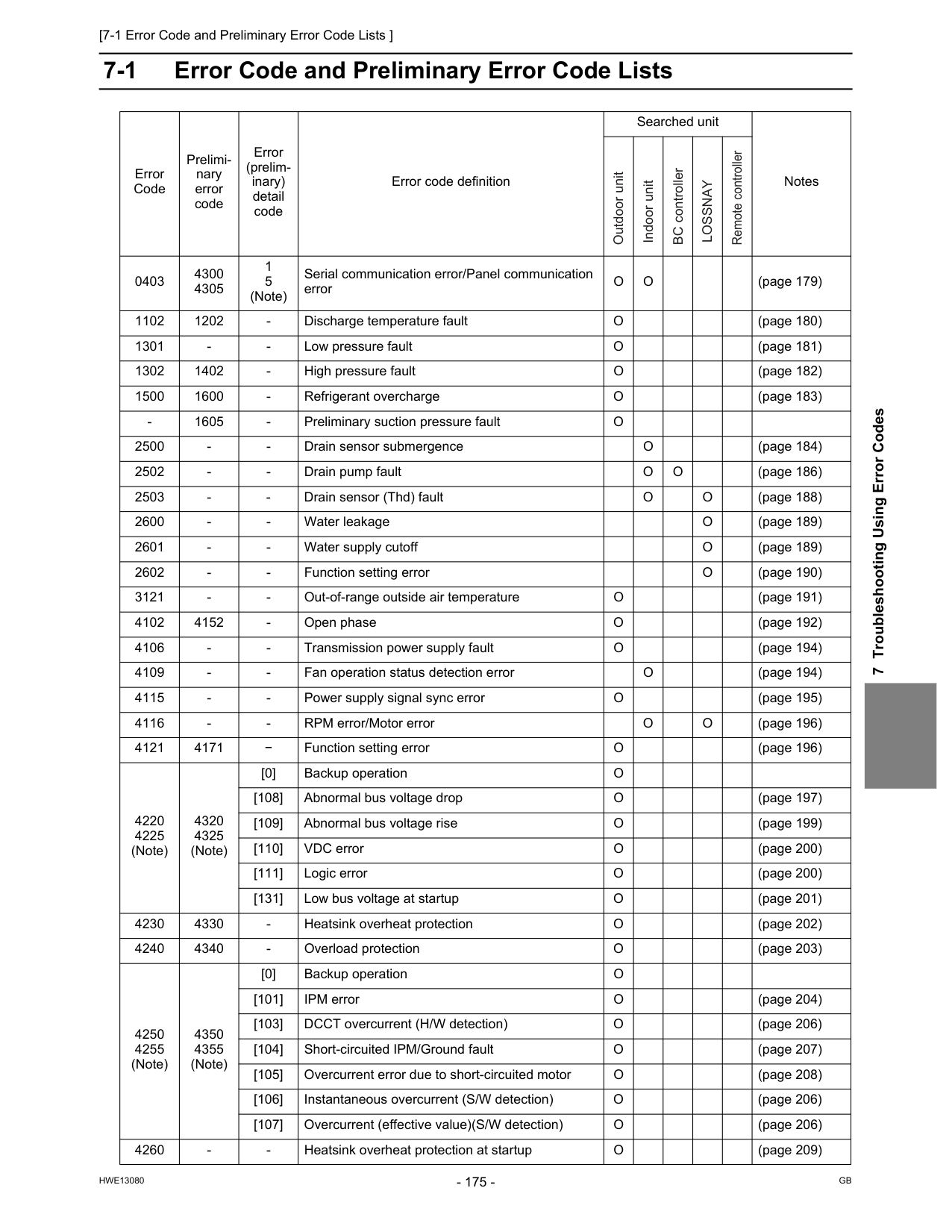
[7-1 Error Code and Preliminary Error Code Lists ]
Hwe13080
Gb
7 Troubleshooting Using Error Codes 7 Troubleshooting Using Error Codes 7-1 Error Code and Preliminary Error Code Lists Error Code Prelimi- nary error code Error (prelim- inary) detail code Error code definition Searched unit Notes 0403 4300 4305 1 5 (Note) Serial communication error/Panel communication errorO
O
(page 179) 1102 1202O
(page 180) 1301O
(page 181) 1302 1402O
(page 182) 1500 1600O
(page 183)O
2500O
(page 184) 2502O
O
(page 186) 2503O
O
(page 188) 2600O
(page 189) 2601O
(page 189) 2602O
(page 190) 3121O
(page 191) 4102 4152O
(page 192) 4106O
(page 194) 4109O
(page 194) 4115O
(page 195) 4116O
O
(page 196) 4121 4171 − Function setting errorO
(page 196) 4220 4225 (Note) 4320 4325 (Note) [0] Backup operationO
[108] Abnormal bus voltage dropO
(page 197) [109] Abnormal bus voltage riseO
(page 199) [110] VDC errorO
(page 200) [111] Logic errorO
(page 200) [131] Low bus voltage at startupO
(page 201) 4230 4330O
(page 202) 4240 4340O
(page 203) 4250 4255 (Note) 4350 4355 (Note) [0] Backup operationO
[101] IPM errorO
(page 204) [103] DCCT overcurrent (H/W detection)O
(page 206) [104] Short-circuited IPM/Ground faultO
(page 207) [105] Overcurrent error due to short-circuited motorO
(page 208) [106] Instantaneous overcurrent (S/W detection)O
(page 206) [107] Overcurrent (effective value)(S/W detection)O
(page 206) 4260O
(page 209) Outdoor unit Indoor unit BC controllerLossnay
Remote controller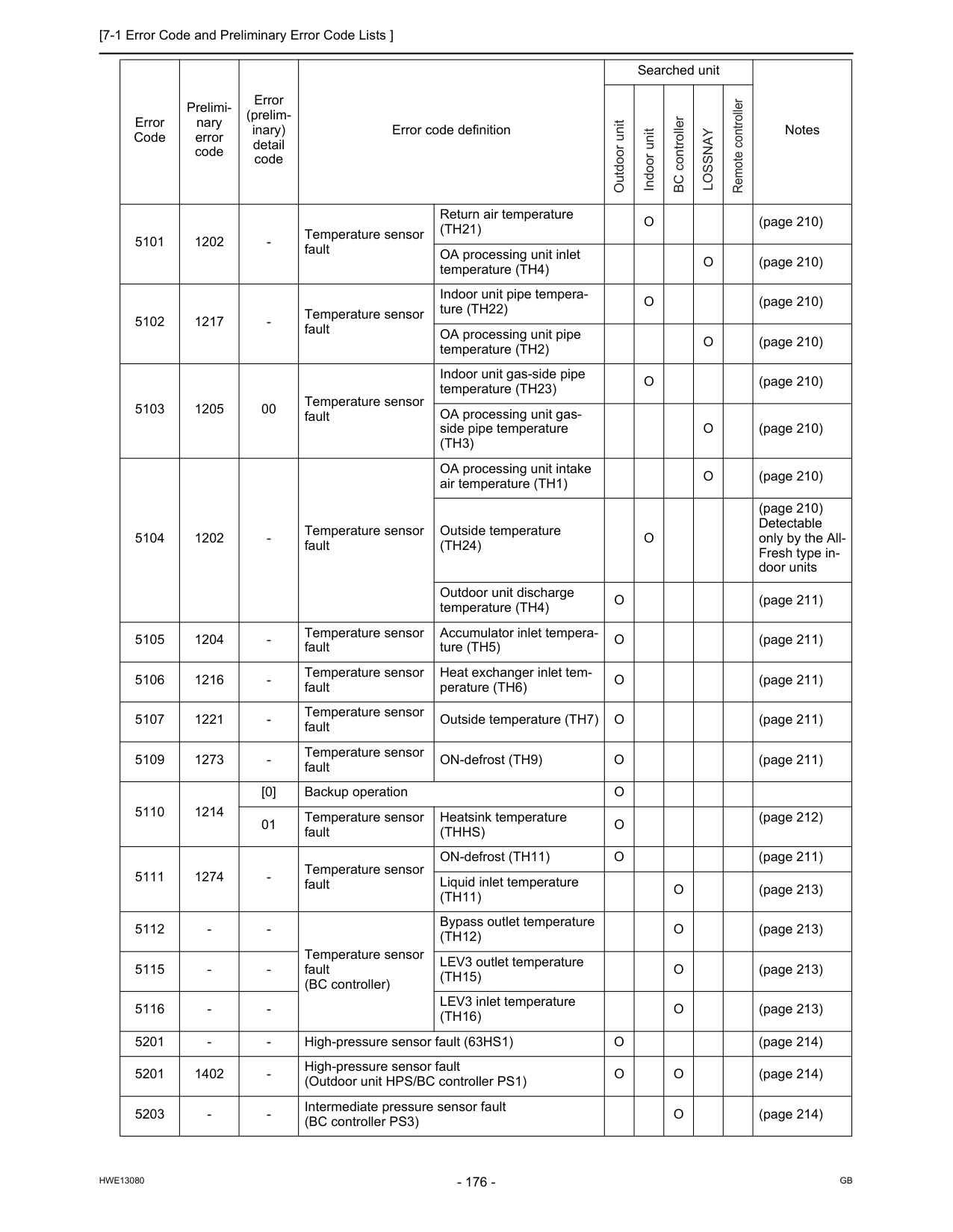
[7-1 Error Code and Preliminary Error Code Lists ]
Hwe13080
Gb
5101 1202(Th21)
O
(page 210) OA processing unit inlet temperature (TH4)O
(page 210) 5102 1217O
(page 210) OA processing unit pipe temperature (TH2)O
(page 210) 5103 1205 00 Temperature sensor fault Indoor unit gas-side pipe temperature (TH23)O
(page 210) OA processing unit gas- side pipe temperature(Th3)
O
(page 210) 5104 1202O
(page 210) Outside temperature(Th24)
O
(page 210) Detectable only by the All- Fresh type in- door units Outdoor unit discharge temperature (TH4)O
(page 211) 5105 1204O
(page 211) 5106 1216O
(page 211) 5107 1221O
(page 211) 5109 1273O
(page 211) 5110 1214 [0] Backup operationO
01 Temperature sensor fault Heatsink temperature(Thhs)
O
(page 212) 5111 1274O
(page 211) Liquid inlet temperature(Th11)
O
(page 213) 5112(Th12)
O
(page 213) 5115(Th15)
O
(page 213) 5116(Th16)
O
(page 213) 5201O
(page 214) 5201 1402O
O
(page 214) 5203O
(page 214) Error Code Prelimi- nary error code Error (prelim- inary) detail code Error code definition Searched unit Notes Outdoor unit Indoor unit BC controllerLossnay
Remote controller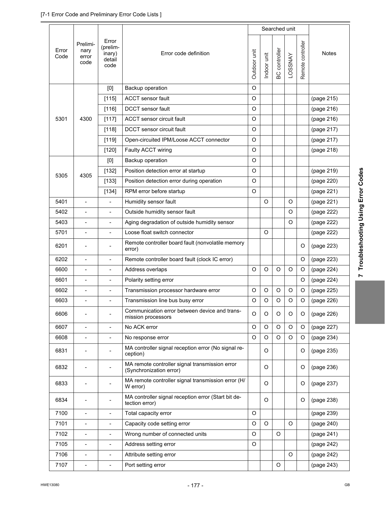
[7-1 Error Code and Preliminary Error Code Lists ]
Hwe13080
Gb
7 Troubleshooting Using Error Codes 5301 4300 [0] Backup operationO
[115] ACCT sensor faultO
(page 215) [116] DCCT sensor faultO
(page 216) [117] ACCT sensor circuit faultO
(page 216) [118] DCCT sensor circuit faultO
(page 217) [119] Open-circuited IPM/Loose ACCT connectorO
(page 217) [120] Faulty ACCT wiringO
(page 218) 5305 4305 [0] Backup operationO
[132] Position detection error at startupO
(page 219) [133] Position detection error during operationO
(page 220) [134] RPM error before startupO
(page 221) 5401O
O
(page 221) 5402O
(page 222) 5403O
(page 222) 5701O
(page 222) 6201O
(page 223) 6202O
(page 223) 6600O
O
O
O
O
(page 224) 6601O
(page 224) 6602O
O
O
O
O
(page 225) 6603O
O
O
O
O
(page 226) 6606O
O
O
O
O
(page 226) 6607O
O
O
O
O
(page 227) 6608O
O
O
O
O
(page 234) 6831O
O
(page 235) 6832O
O
(page 236) 6833O
O
(page 237) 6834O
O
(page 238) 7100O
(page 239) 7101O
O
O
(page 240) 7102O
O
(page 241) 7105O
(page 242) 7106O
(page 242) 7107O
(page 243) Error Code Prelimi- nary error code Error (prelim- inary) detail code Error code definition Searched unit Notes Outdoor unit Indoor unit BC controllerLossnay
Remote controller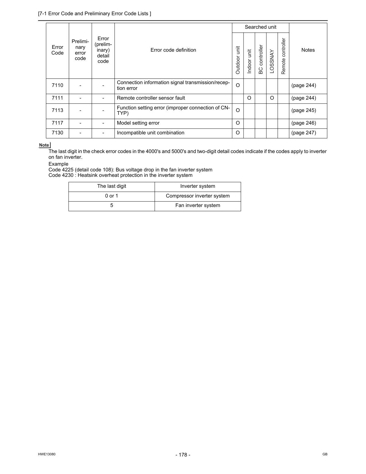
[7-1 Error Code and Preliminary Error Code Lists ]
Hwe13080
Gb
The last digit in the check error codes in the 4000's and 5000's and two-digit detail codes indicate if the codes apply to inverter on fan inverter. Example Code 4225 (detail code 108): Bus voltage drop in the fan inverter system Code 4230 : Heatsink overheat protection in the inverter system 7110O
(page 244) 7111O
O
(page 244) 7113Typ)
O
(page 245) 7117O
(page 246) 7130O
(page 247) The last digit Inverter system 0 or 1 Compressor inverter system 5 Fan inverter system Error Code Prelimi- nary error code Error (prelim- inary) detail code Error code definition Searched unit Notes Outdoor unit Indoor unit BC controllerLossnay
Remote controller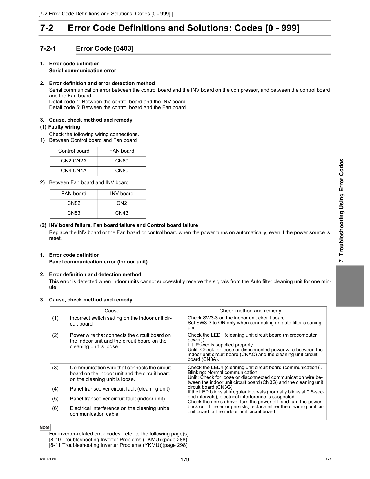
[7-2 Error Code Definitions and Solutions: Codes [0 - 999] ]
Hwe13080
Gb
7 Troubleshooting Using Error Codes 7-2 Error Code Definitions and Solutions: Codes [0 - 999] 7-2-1 Error Code [0403]Cn2,Cn2A
Cn80
Cn4,Cn4A
Cn80
FAN board INV boardCn82
Cn2
Cn83
Cn43
Cause Check method and remedy (1) Incorrect switch setting on the indoor unit cir- cuit board Check SW3-3 on the indoor unit circuit board Set SW3-3 to ON only when connecting an auto filter cleaning unit. (2) Power wire that connects the circuit board on the indoor unit and the circuit board on the cleaning unit is loose. Check the LED1 (cleaning unit circuit board (microcomputer power)). Lit: Power is supplied properly. Unlit: Check for loose or disconnected power wire between the indoor unit circuit board (CNAC) and the cleaning unit circuit board (CN3A). (3) Communication wire that connects the circuit board on the indoor unit and the circuit board on the cleaning unit is loose. Check the LED4 (cleaning unit circuit board (communication)). Blinking: Normal communication Unlit: Check for loose or disconnected communication wire be- tween the indoor unit circuit board (CN3G) and the cleaning unit circuit board (CN3G). If the LED blinks at irregular intervals (normally blinks at 0.5-sec- ond intervals), electrical interference is suspected. Check the items above, turn the power off, and turn the power back on. If the error persists, replace either the cleaning unit cir- cuit board or the indoor unit circuit board. (4) Panel transceiver circuit fault (cleaning unit) (5) Panel transceiver circuit fault (indoor unit) (6) Electrical interference on the cleaning unit's communication cable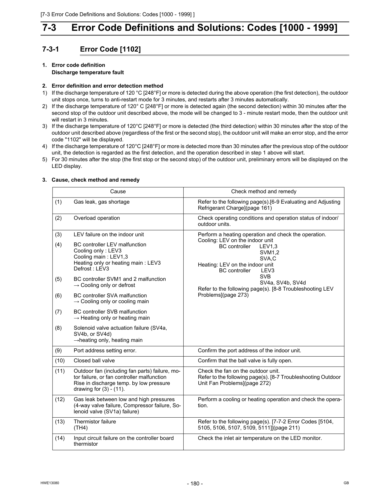
[7-3 Error Code Definitions and Solutions: Codes [1000 - 1999] ]
Hwe13080
Gb
7-3 Error Code Definitions and Solutions: Codes [1000 - 1999] 7-3-1 Error Code [1102]Svm1,2
Sva,C
Heating: LEV on the indoor unit BC controller LEV3Svb
SV4a, SV4b, SV4d Refer to the following page(s). [8-8 Troubleshooting LEV Problems](page 273) (4) BC controller LEV malfunction Cooling only : LEV3 Cooling main : LEV1,3 Heating only or heating main : LEV3 Defrost : LEV3 (5) BC controller SVM1 and 2 malfunction → Cooling only or defrost (6) BC controller SVA malfunction → Cooling only or cooling main (7) BC controller SVB malfunction → Heating only or heating main (8) Solenoid valve actuation failure (SV4a, SV4b, or SV4d) →heating only, heating main (9) Port address setting error. Confirm the port address of the indoor unit. (10) Closed ball valve Confirm that the ball valve is fully open. (11) Outdoor fan (including fan parts) failure, mo- tor failure, or fan controller malfunction Rise in discharge temp. by low pressure drawing for (3) - (11). Check the fan on the outdoor unit. Refer to the following page(s). [8-7 Troubleshooting Outdoor Unit Fan Problems](page 272) (12) Gas leak between low and high pressures (4-way valve failure, Compressor failure, So- lenoid valve (SV1a) failure) Perform a cooling or heating operation and check the opera- tion. (13) Thermistor failure(Th4)
Refer to the following page(s). [7-7-2 Error Codes [5104, 5105, 5106, 5107, 5109, 5111]](page 211) (14) Input circuit failure on the controller board thermistor Check the inlet air temperature on the LED monitor.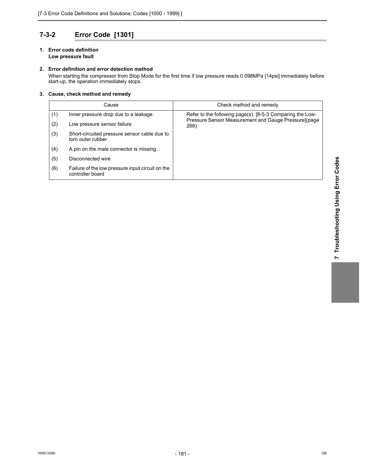
[7-3 Error Code Definitions and Solutions: Codes [1000 - 1999] ]
Hwe13080
Gb
7 Troubleshooting Using Error Codes 7-3-2 Error Code [1301]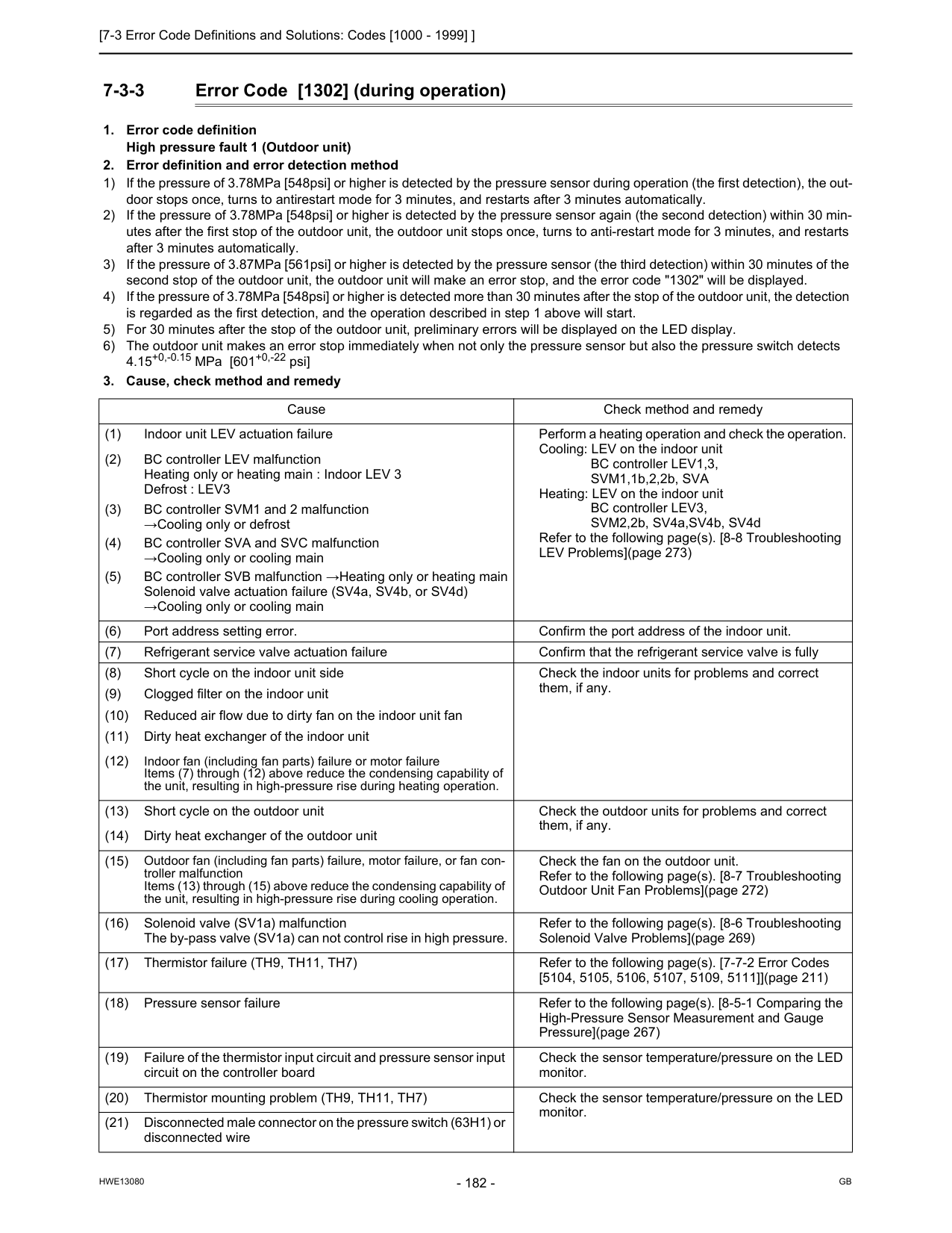
[7-3 Error Code Definitions and Solutions: Codes [1000 - 1999] ]
Hwe13080
Gb
7-3-3 Error Code [1302] (during operation)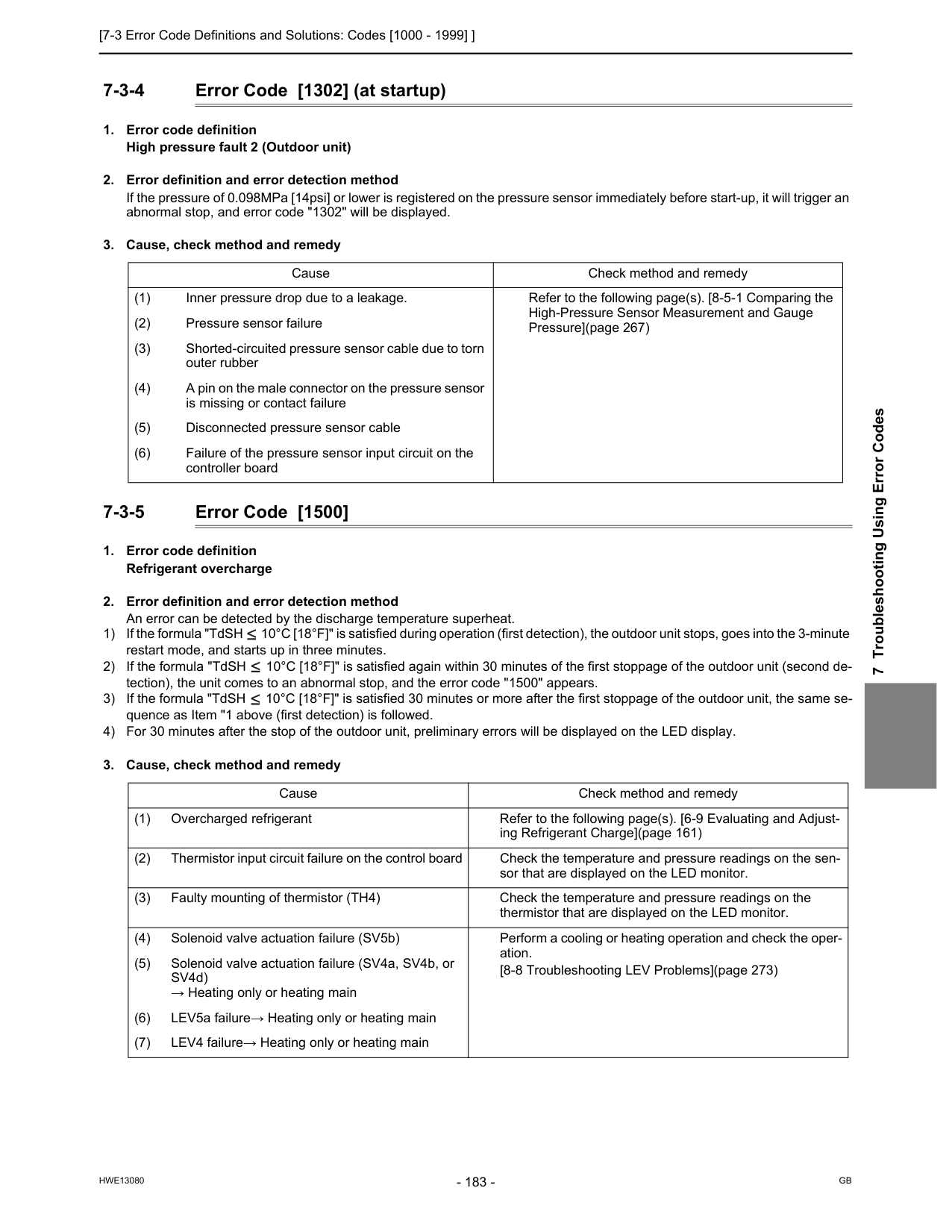
[7-3 Error Code Definitions and Solutions: Codes [1000 - 1999] ]
Hwe13080
Gb
7 Troubleshooting Using Error Codes 7-3-4 Error Code [1302] (at startup)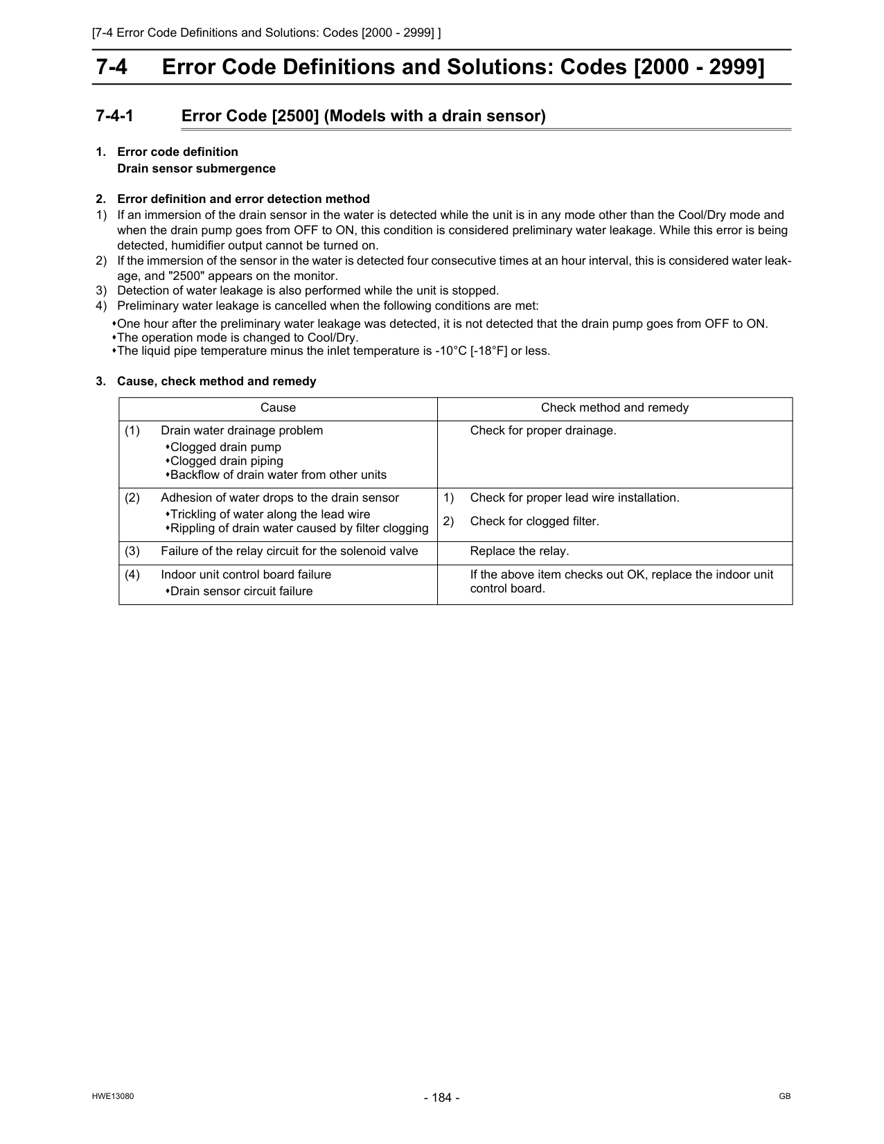
[7-4 Error Code Definitions and Solutions: Codes [2000 - 2999] ]
Hwe13080
Gb
7-4 Error Code Definitions and Solutions: Codes [2000 - 2999] 7-4-1 Error Code [2500] (Models with a drain sensor)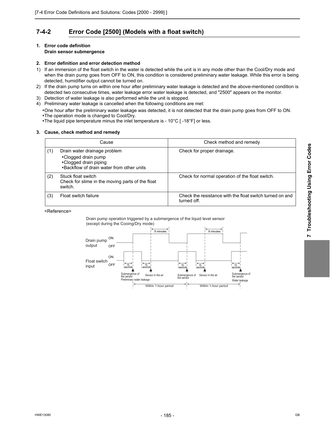
[7-4 Error Code Definitions and Solutions: Codes [2000 - 2999] ]
Hwe13080
Gb
7 Troubleshooting Using Error Codes 7-4-2 Error Code [2500] (Models with a float switch)On
Off
On
Off
Drain pump operation triggered by a submergence of the liquid level sensor (except during the Cooing/Dry mode) Drain pump output Float switch input Submergence of the sensor Submergence of the sensor Preliminary water leakage Submergence of the sensor Water leakage Sensor in the air Sensor in the air Within 1-hour period Within 1-hour period
[7-4 Error Code Definitions and Solutions: Codes [2000 - 2999] ]
Hwe13080
Gb
7-4-3 Error Code [2502] (Models with a drain sensor)
[7-4 Error Code Definitions and Solutions: Codes [2000 - 2999] ]
Hwe13080
Gb
7 Troubleshooting Using Error Codes 7-4-4 Error Code [2502] (Models with a float switch)
[7-4 Error Code Definitions and Solutions: Codes [2000 - 2999] ]
Hwe13080
Gb
7-4-5 Error Code [2503]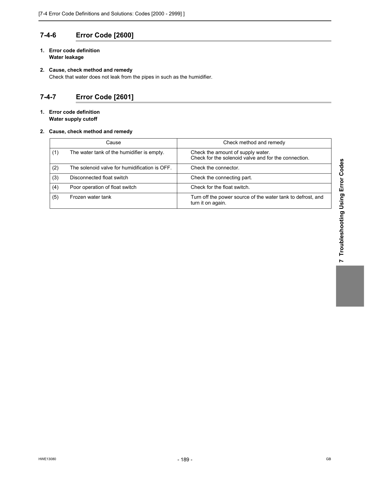
[7-4 Error Code Definitions and Solutions: Codes [2000 - 2999] ]
Hwe13080
Gb
7 Troubleshooting Using Error Codes 7-4-6 Error Code [2600]
[7-4 Error Code Definitions and Solutions: Codes [2000 - 2999] ]
Hwe13080
Gb
7-4-8 Error Code [2602]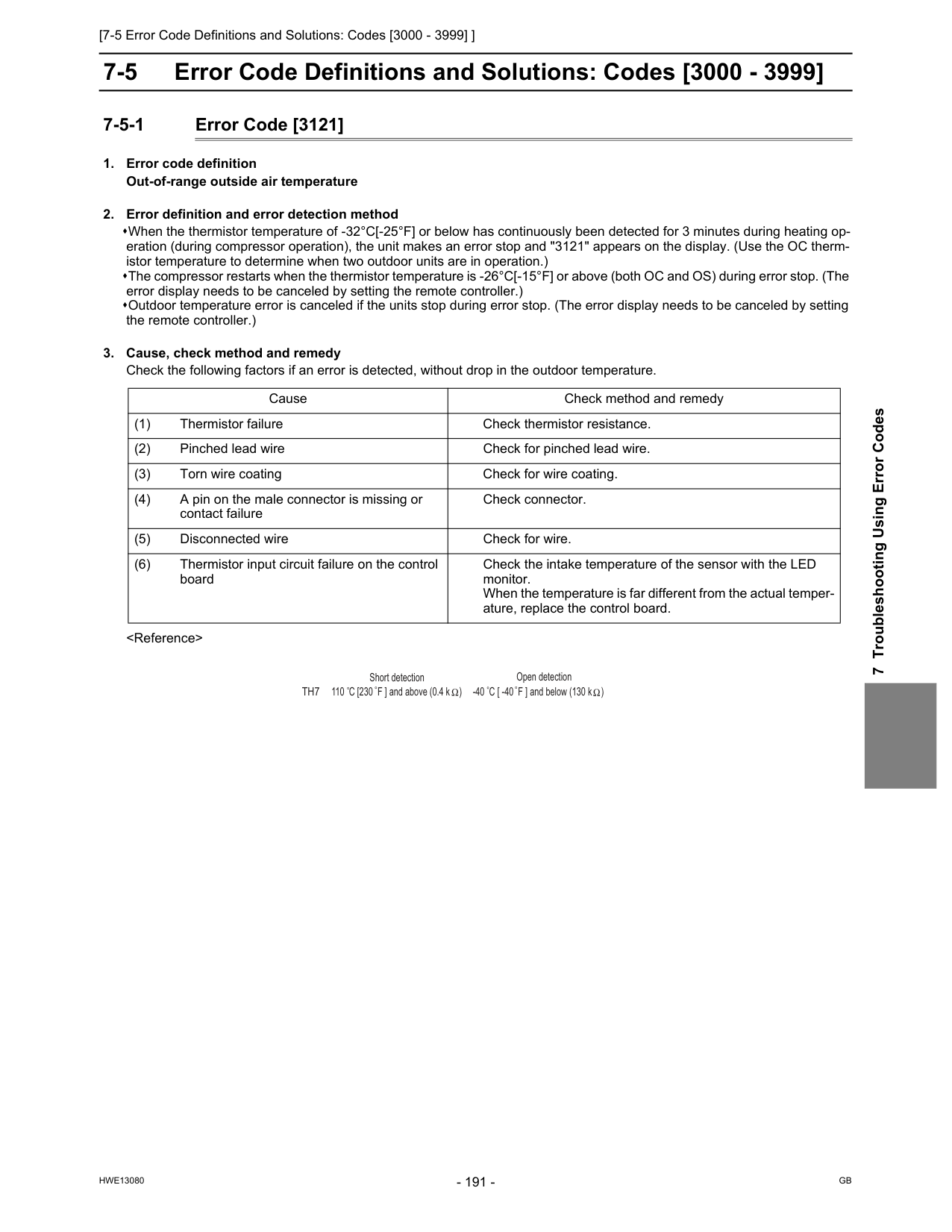
[7-5 Error Code Definitions and Solutions: Codes [3000 - 3999] ]
Hwe13080
Gb
7 Troubleshooting Using Error Codes 7-5 Error Code Definitions and Solutions: Codes [3000 - 3999] 7-5-1 Error Code [3121]Th7
Open detection -40 C [ -40 F ] and below (130 k ) Short detection 110 C [230 F ] and above (0.4 k )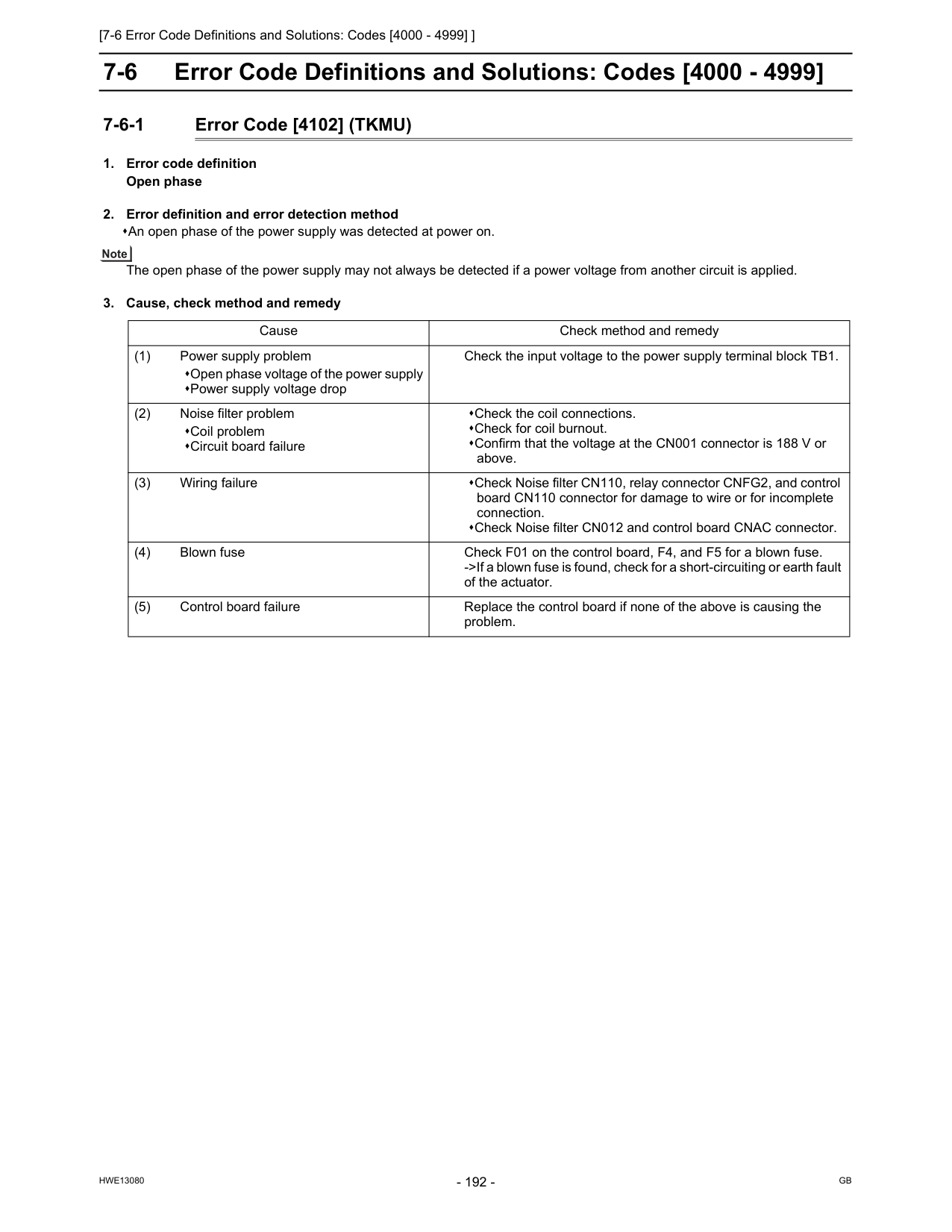
[7-6 Error Code Definitions and Solutions: Codes [4000 - 4999] ]
Hwe13080
Gb
7-6 Error Code Definitions and Solutions: Codes [4000 - 4999] 7-6-1 Error Code [4102] (TKMU)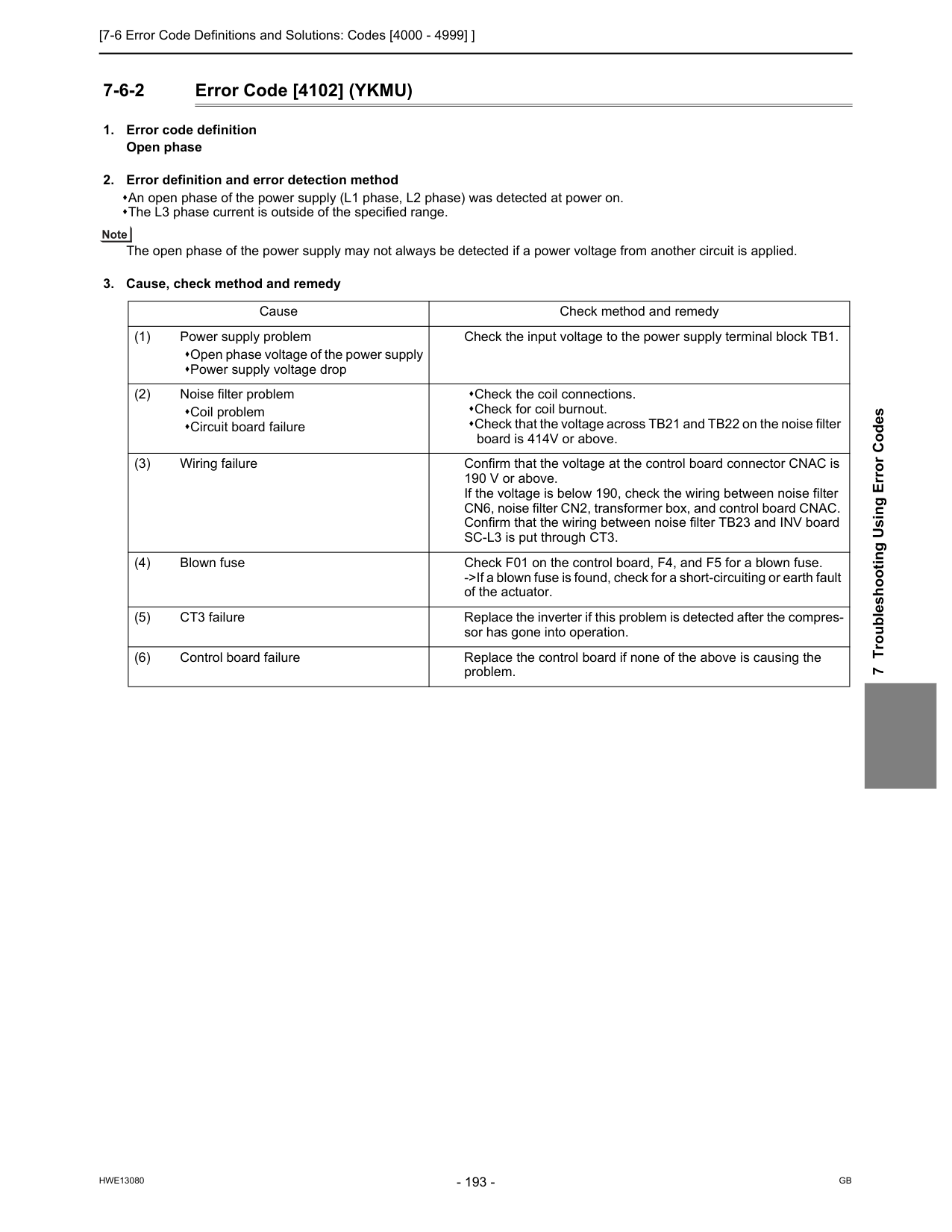
[7-6 Error Code Definitions and Solutions: Codes [4000 - 4999] ]
Hwe13080
Gb
7 Troubleshooting Using Error Codes 7-6-2 Error Code [4102] (YKMU)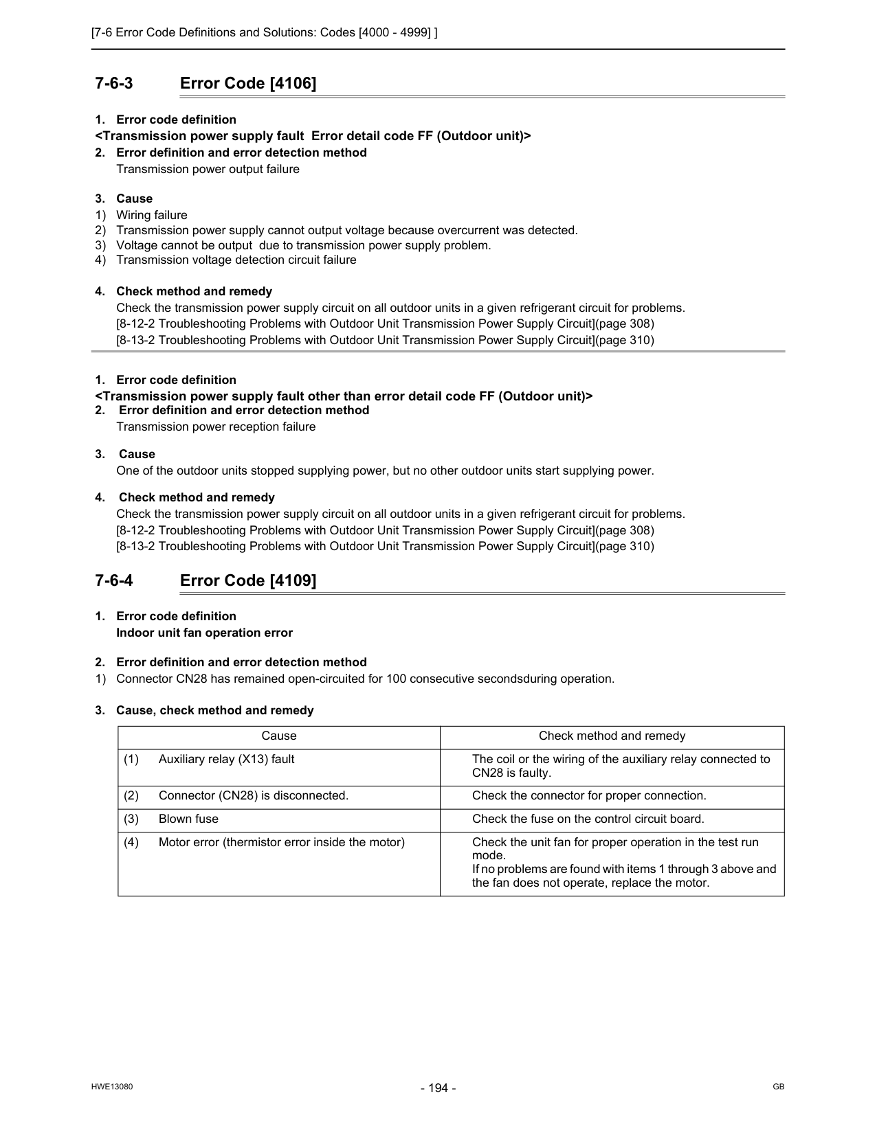
[7-6 Error Code Definitions and Solutions: Codes [4000 - 4999] ]
Hwe13080
Gb
7-6-3 Error Code [4106]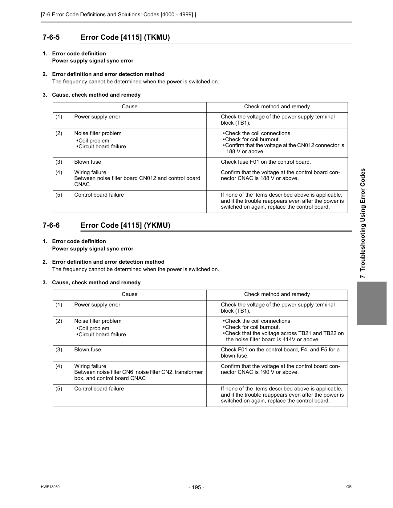
[7-6 Error Code Definitions and Solutions: Codes [4000 - 4999] ]
Hwe13080
Gb
7 Troubleshooting Using Error Codes 7-6-5 Error Code [4115] (TKMU)Cnac
Confirm that the voltage at the control board con- nector CNAC is 188 V or above. (5) Control board failure If none of the items described above is applicable, and if the trouble reappears even after the power is switched on again, replace the control board. Cause Check method and remedy (1) Power supply error Check the voltage of the power supply terminal block (TB1). (2) Noise filter problem Coil problem Circuit board failure Check the coil connections. Check for coil burnout. Check that the voltage across TB21 and TB22 on the noise filter board is 414V or above. (3) Blown fuse Check F01 on the control board, F4, and F5 for a blown fuse. (4) Wiring failure Between noise filter CN6, noise filter CN2, transformer box, and control board CNAC Confirm that the voltage at the control board con- nector CNAC is 190 V or above. (5) Control board failure If none of the items described above is applicable, and if the trouble reappears even after the power is switched on again, replace the control board.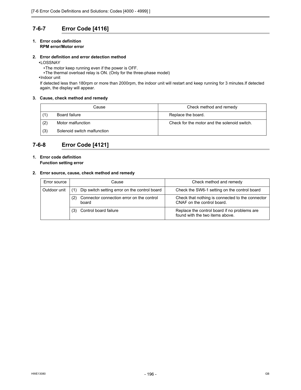
[7-6 Error Code Definitions and Solutions: Codes [4000 - 4999] ]
Hwe13080
Gb
7-6-7 Error Code [4116]Lossnay
∗The motor keep running even if the power is OFF. ∗The thermal overload relay is ON. (Only for the three-phase model) Indoor unit If detected less than 180rpm or more than 2000rpm, the indoor unit will restart and keep running for 3 minutes.If detected again, the display will appear.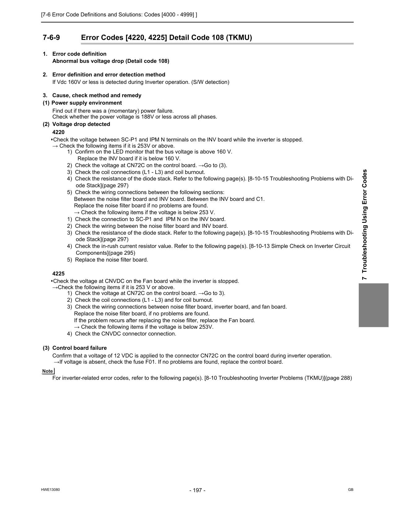
[7-6 Error Code Definitions and Solutions: Codes [4000 - 4999] ]
Hwe13080
Gb
7 Troubleshooting Using Error Codes 7-6-9 Error Codes [4220, 4225] Detail Code 108 (TKMU)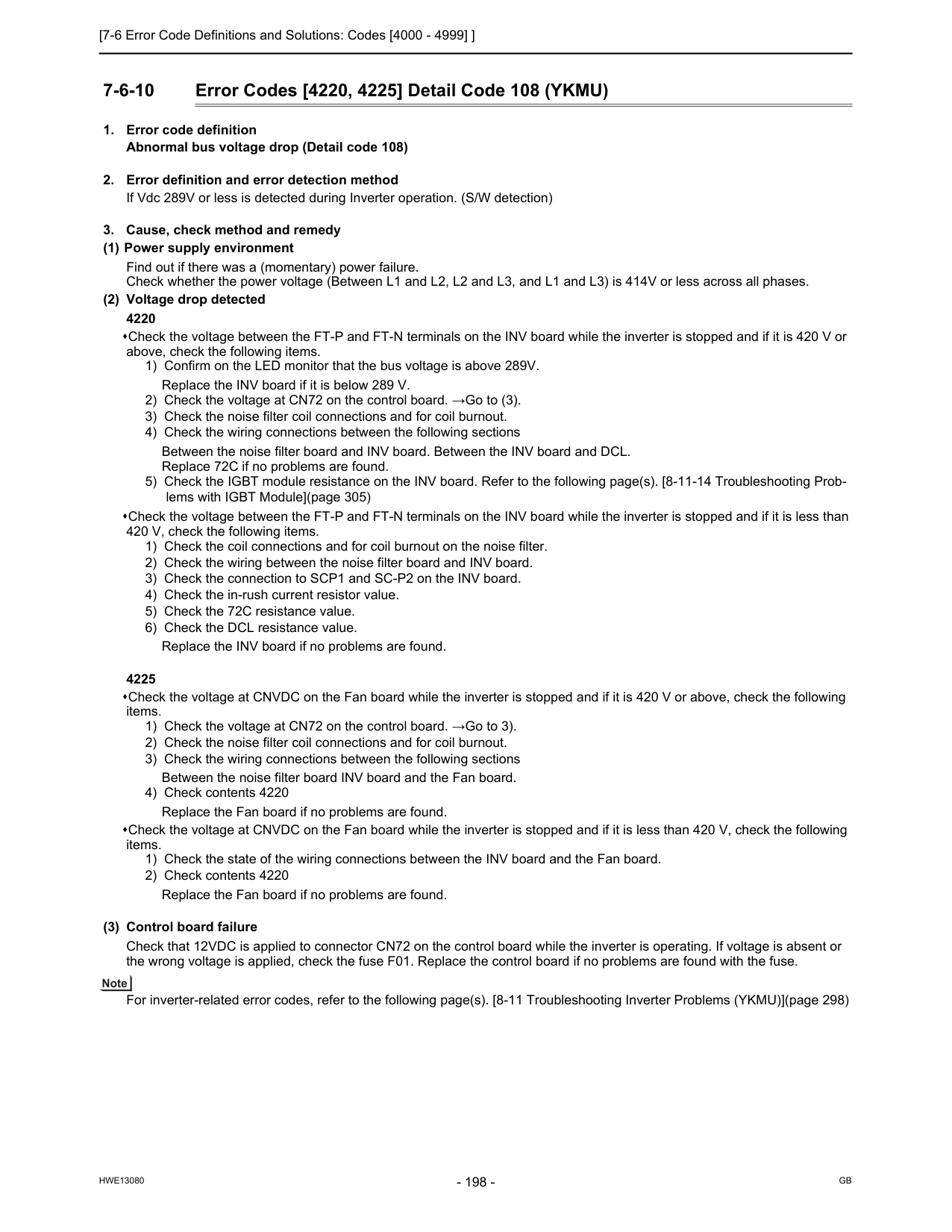
[7-6 Error Code Definitions and Solutions: Codes [4000 - 4999] ]
Hwe13080
Gb
7-6-10 Error Codes [4220, 4225] Detail Code 108 (YKMU)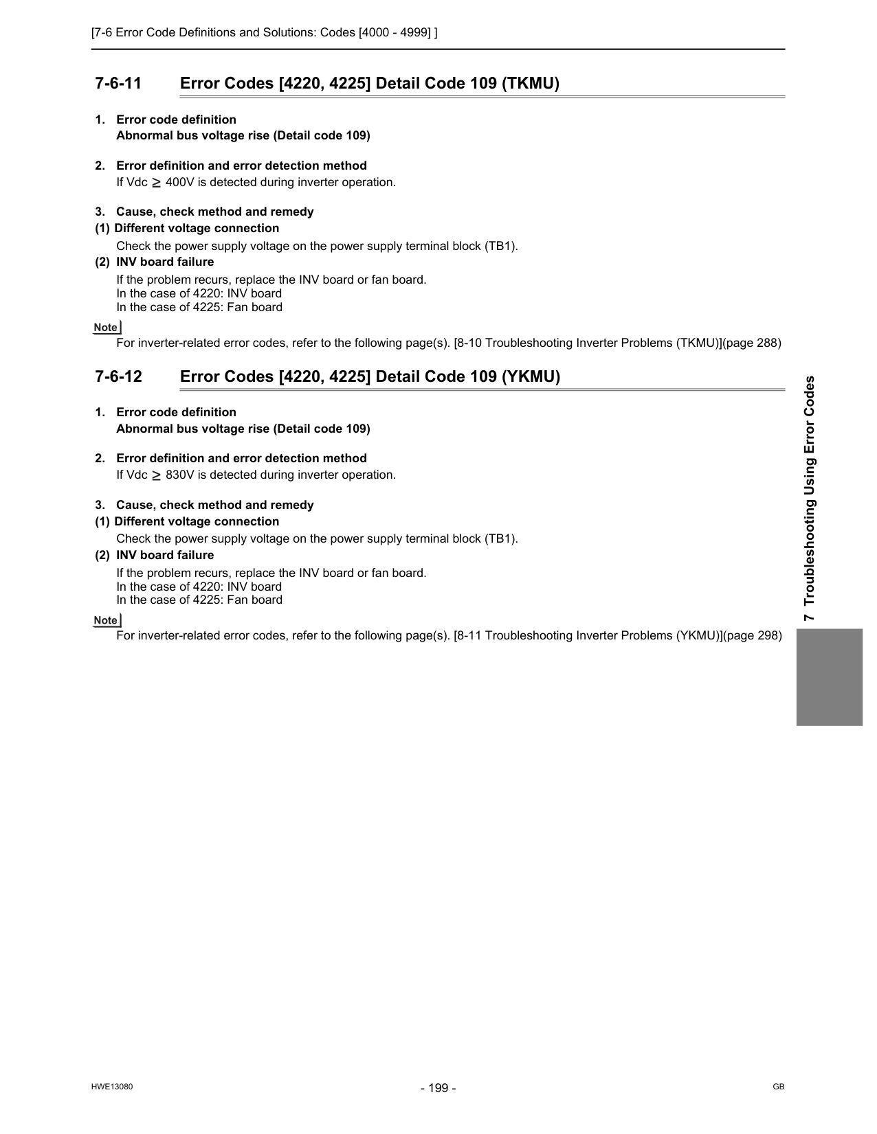
[7-6 Error Code Definitions and Solutions: Codes [4000 - 4999] ]
Hwe13080
Gb
7 Troubleshooting Using Error Codes 7-6-11 Error Codes [4220, 4225] Detail Code 109 (TKMU)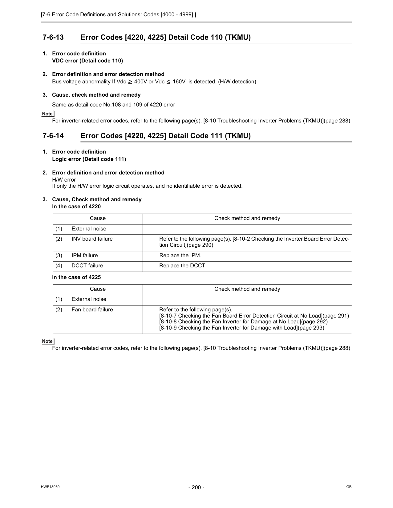
[7-6 Error Code Definitions and Solutions: Codes [4000 - 4999] ]
Hwe13080
Gb
7-6-13 Error Codes [4220, 4225] Detail Code 110 (TKMU)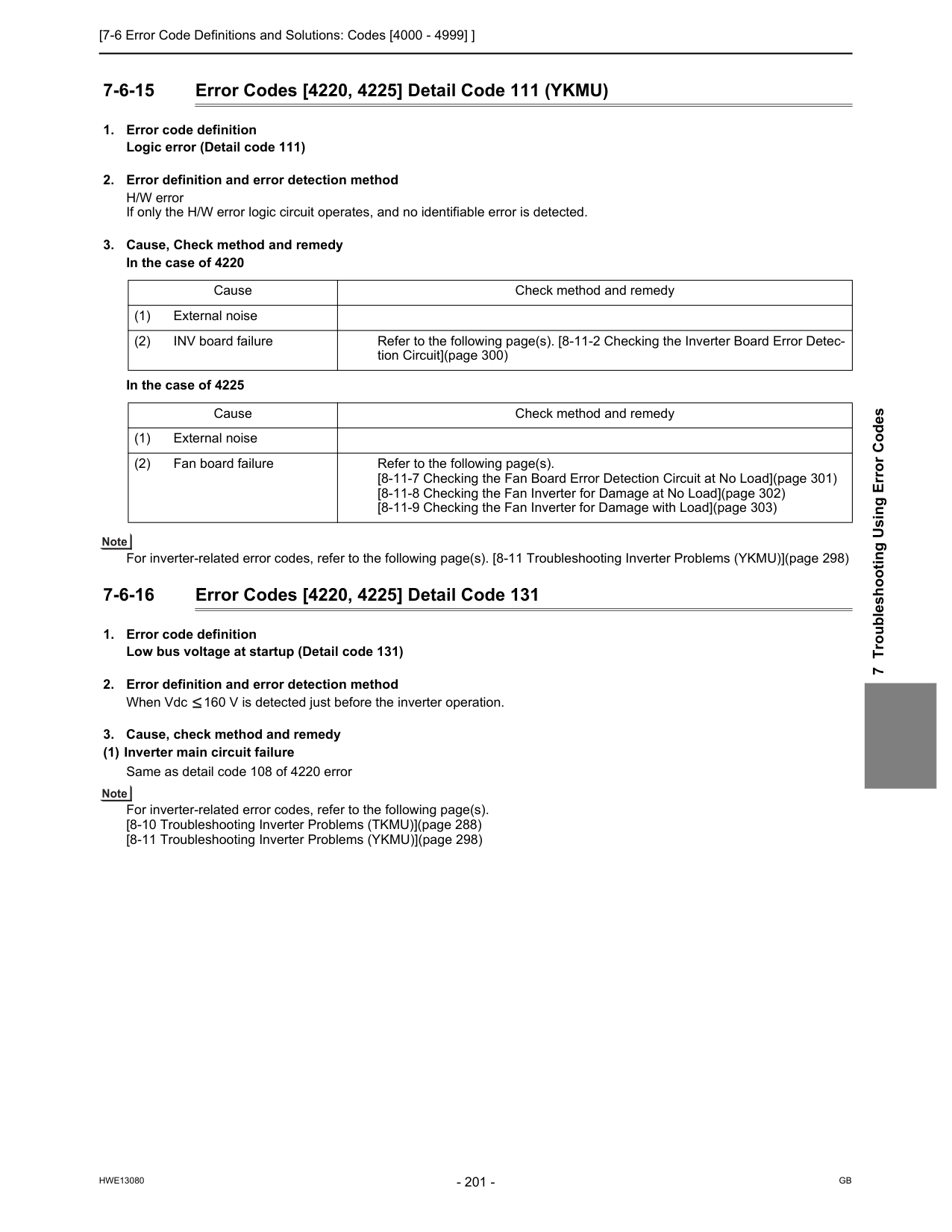
[7-6 Error Code Definitions and Solutions: Codes [4000 - 4999] ]
Hwe13080
Gb
7 Troubleshooting Using Error Codes 7-6-15 Error Codes [4220, 4225] Detail Code 111 (YKMU)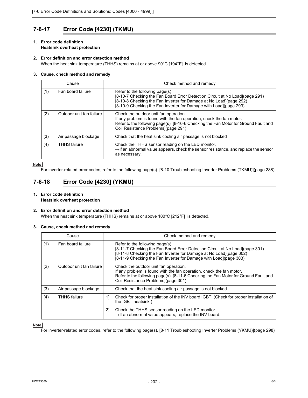
[7-6 Error Code Definitions and Solutions: Codes [4000 - 4999] ]
Hwe13080
Gb
7-6-17 Error Code [4230] (TKMU)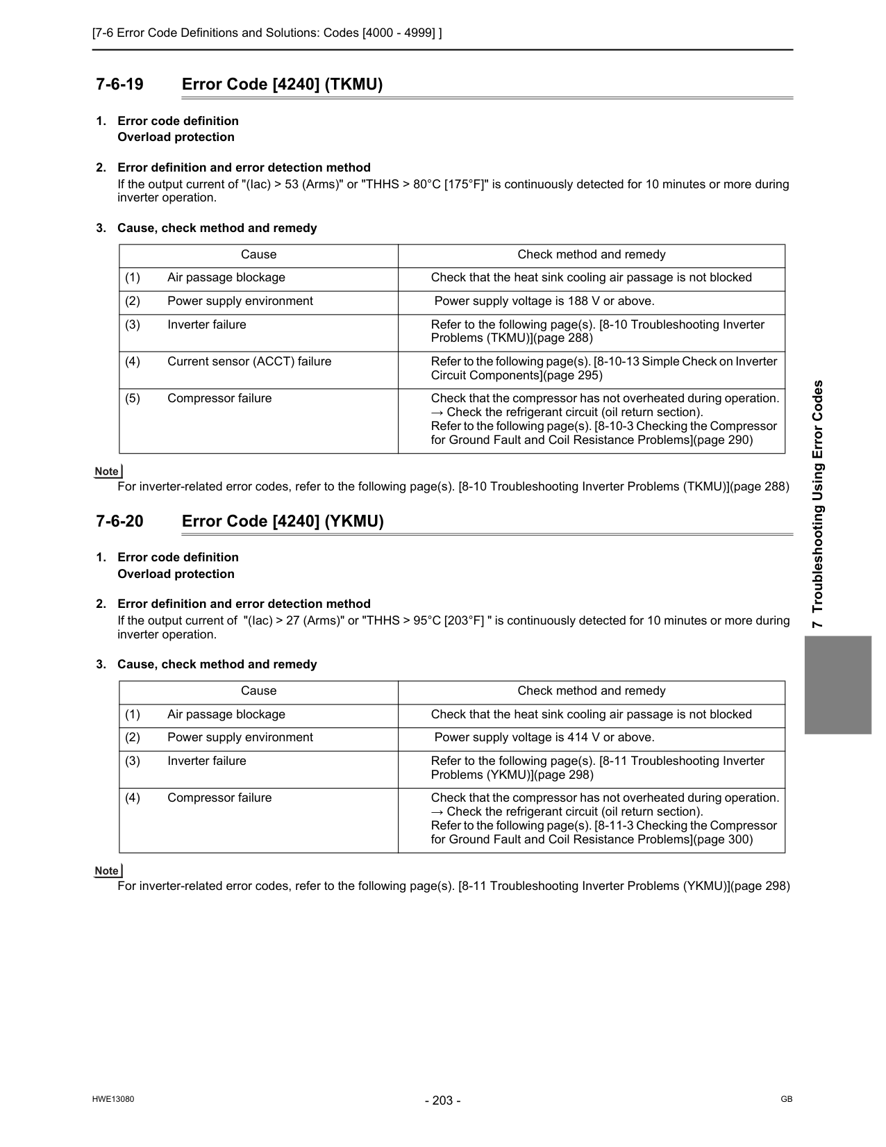
[7-6 Error Code Definitions and Solutions: Codes [4000 - 4999] ]
Hwe13080
Gb
7 Troubleshooting Using Error Codes 7-6-19 Error Code [4240] (TKMU)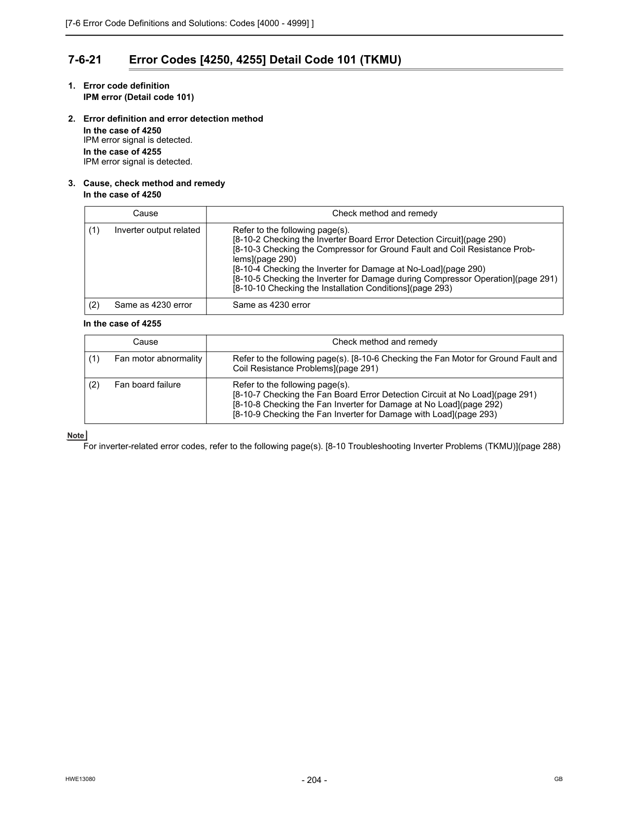
[7-6 Error Code Definitions and Solutions: Codes [4000 - 4999] ]
Hwe13080
Gb
7-6-21 Error Codes [4250, 4255] Detail Code 101 (TKMU)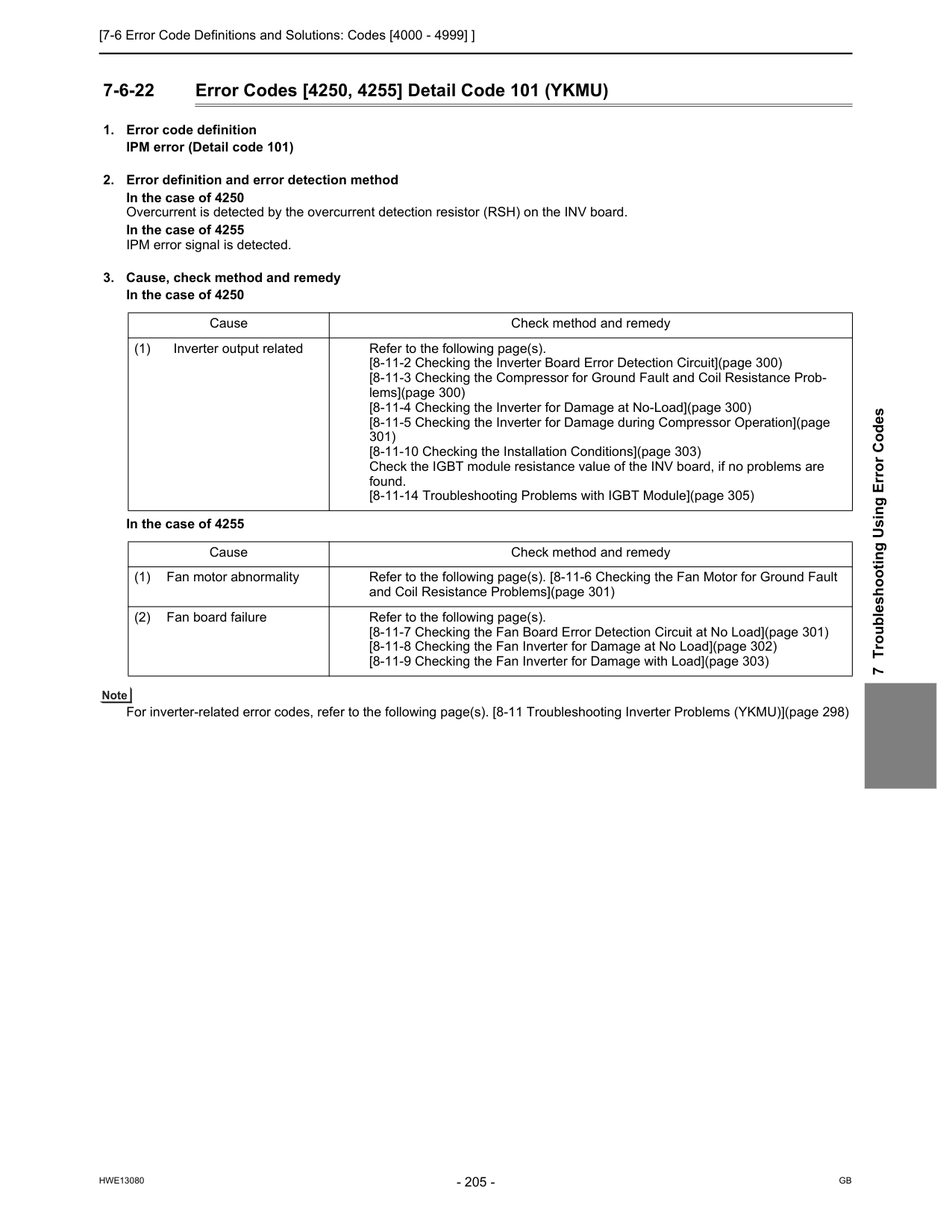
[7-6 Error Code Definitions and Solutions: Codes [4000 - 4999] ]
Hwe13080
Gb
7 Troubleshooting Using Error Codes 7-6-22 Error Codes [4250, 4255] Detail Code 101 (YKMU)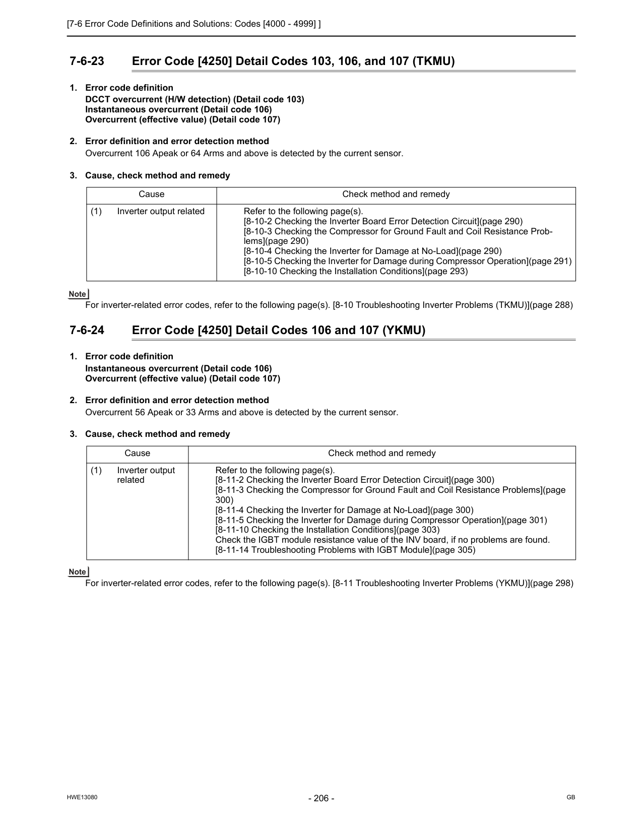
[7-6 Error Code Definitions and Solutions: Codes [4000 - 4999] ]
Hwe13080
Gb
7-6-23 Error Code [4250] Detail Codes 103, 106, and 107 (TKMU)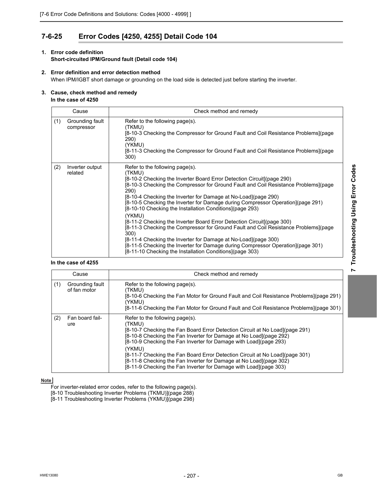
[7-6 Error Code Definitions and Solutions: Codes [4000 - 4999] ]
Hwe13080
Gb
7 Troubleshooting Using Error Codes 7-6-25 Error Codes [4250, 4255] Detail Code 104(Tkmu)
[8-10-3 Checking the Compressor for Ground Fault and Coil Resistance Problems](page 290)(Ykmu)
[8-11-3 Checking the Compressor for Ground Fault and Coil Resistance Problems](page 300) (2) Inverter output related Refer to the following page(s).(Tkmu)
[8-10-2 Checking the Inverter Board Error Detection Circuit](page 290) [8-10-3 Checking the Compressor for Ground Fault and Coil Resistance Problems](page 290) [8-10-4 Checking the Inverter for Damage at No-Load](page 290) [8-10-5 Checking the Inverter for Damage during Compressor Operation](page 291) [8-10-10 Checking the Installation Conditions](page 293)(Ykmu)
[8-11-2 Checking the Inverter Board Error Detection Circuit](page 300) [8-11-3 Checking the Compressor for Ground Fault and Coil Resistance Problems](page 300) [8-11-4 Checking the Inverter for Damage at No-Load](page 300) [8-11-5 Checking the Inverter for Damage during Compressor Operation](page 301) [8-11-10 Checking the Installation Conditions](page 303) Cause Check method and remedy (1) Grounding fault of fan motor Refer to the following page(s).(Tkmu)
[8-10-6 Checking the Fan Motor for Ground Fault and Coil Resistance Problems](page 291)(Ykmu)
[8-11-6 Checking the Fan Motor for Ground Fault and Coil Resistance Problems](page 301) (2) Fan board fail- ure Refer to the following page(s).(Tkmu)
[8-10-7 Checking the Fan Board Error Detection Circuit at No Load](page 291) [8-10-8 Checking the Fan Inverter for Damage at No Load](page 292) [8-10-9 Checking the Fan Inverter for Damage with Load](page 293)(Ykmu)
[8-11-7 Checking the Fan Board Error Detection Circuit at No Load](page 301) [8-11-8 Checking the Fan Inverter for Damage at No Load](page 302) [8-11-9 Checking the Fan Inverter for Damage with Load](page 303)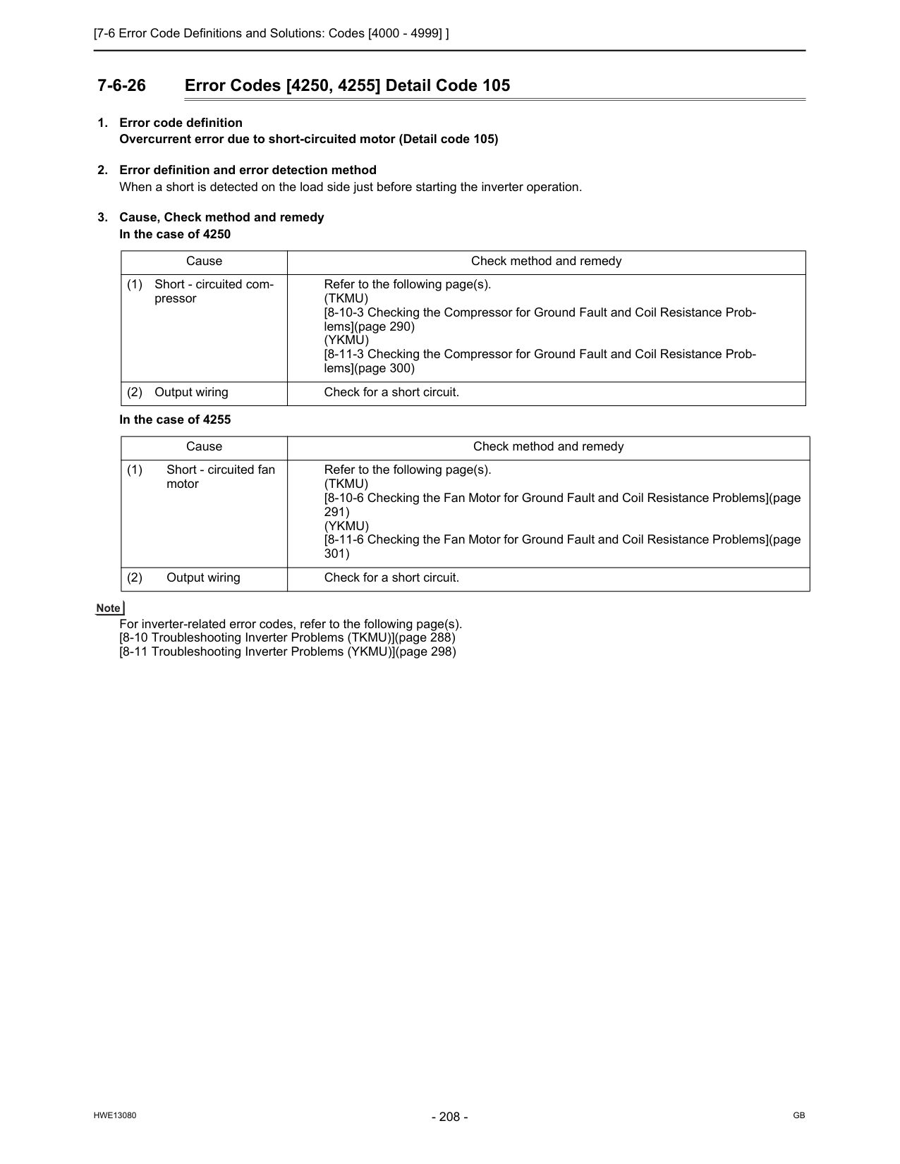
[7-6 Error Code Definitions and Solutions: Codes [4000 - 4999] ]
Hwe13080
Gb
7-6-26 Error Codes [4250, 4255] Detail Code 105(Tkmu)
[8-10-3 Checking the Compressor for Ground Fault and Coil Resistance Prob- lems](page 290)(Ykmu)
[8-11-3 Checking the Compressor for Ground Fault and Coil Resistance Prob- lems](page 300) (2) Output wiring Check for a short circuit. Cause Check method and remedy (1) Short - circuited fan motor Refer to the following page(s).(Tkmu)
[8-10-6 Checking the Fan Motor for Ground Fault and Coil Resistance Problems](page 291)(Ykmu)
[8-11-6 Checking the Fan Motor for Ground Fault and Coil Resistance Problems](page 301) (2) Output wiring Check for a short circuit.
[7-6 Error Code Definitions and Solutions: Codes [4000 - 4999] ]
Hwe13080
Gb
7 Troubleshooting Using Error Codes 7-6-27 Error Code [4260] (TKMU)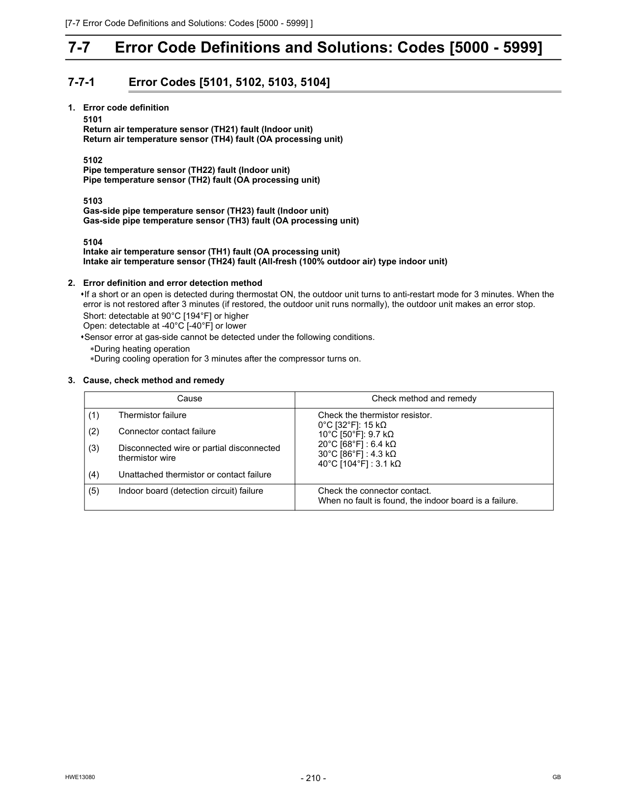
[7-7 Error Code Definitions and Solutions: Codes [5000 - 5999] ]
Hwe13080
Gb
7-7 Error Code Definitions and Solutions: Codes [5000 - 5999] 7-7-1 Error Codes [5101, 5102, 5103, 5104]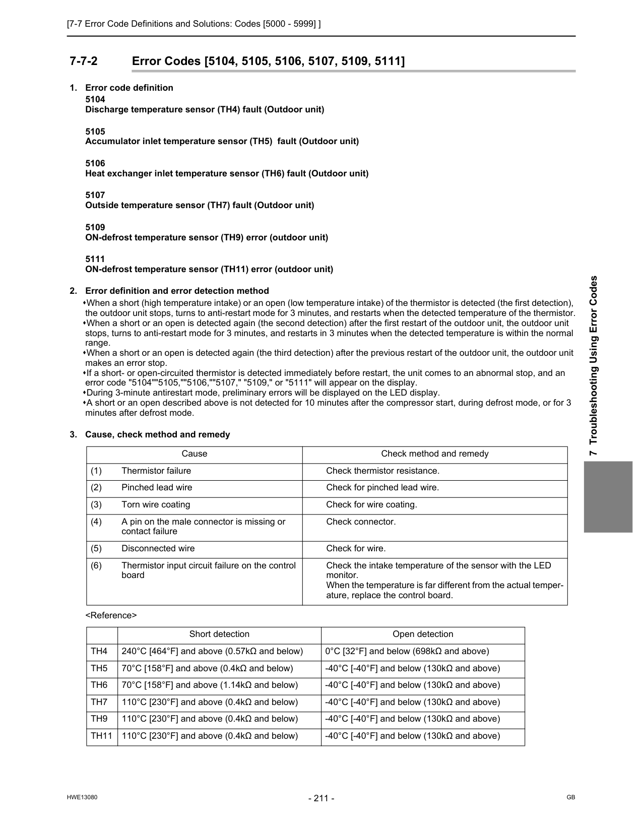
[7-7 Error Code Definitions and Solutions: Codes [5000 - 5999] ]
Hwe13080
Gb
7 Troubleshooting Using Error Codes 7-7-2 Error Codes [5104, 5105, 5106, 5107, 5109, 5111]Th4
240°C [464°F] and above (0.57kΩ and below) 0°C [32°F] and below (698kΩ and above)Th5
70°C [158°F] and above (0.4kΩ and below) -40°C [-40°F] and below (130kΩ and above)Th6
70°C [158°F] and above (1.14kΩ and below) -40°C [-40°F] and below (130kΩ and above)Th7
110°C [230°F] and above (0.4kΩ and below) -40°C [-40°F] and below (130kΩ and above)Th9
110°C [230°F] and above (0.4kΩ and below) -40°C [-40°F] and below (130kΩ and above)Th11
110°C [230°F] and above (0.4kΩ and below) -40°C [-40°F] and below (130kΩ and above)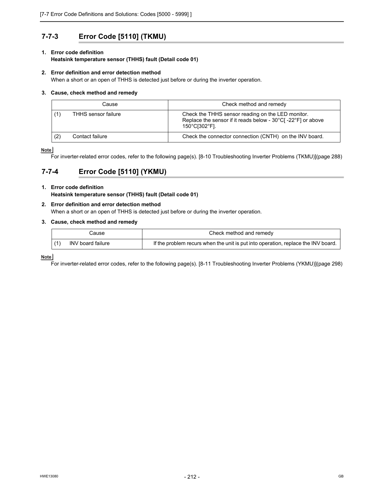
[7-7 Error Code Definitions and Solutions: Codes [5000 - 5999] ]
Hwe13080
Gb
7-7-3 Error Code [5110] (TKMU)150°C[302°F].
(2) Contact failure Check the connector connection (CNTH) on the INV board. Cause Check method and remedy (1) INV board failure If the problem recurs when the unit is put into operation, replace the INV board.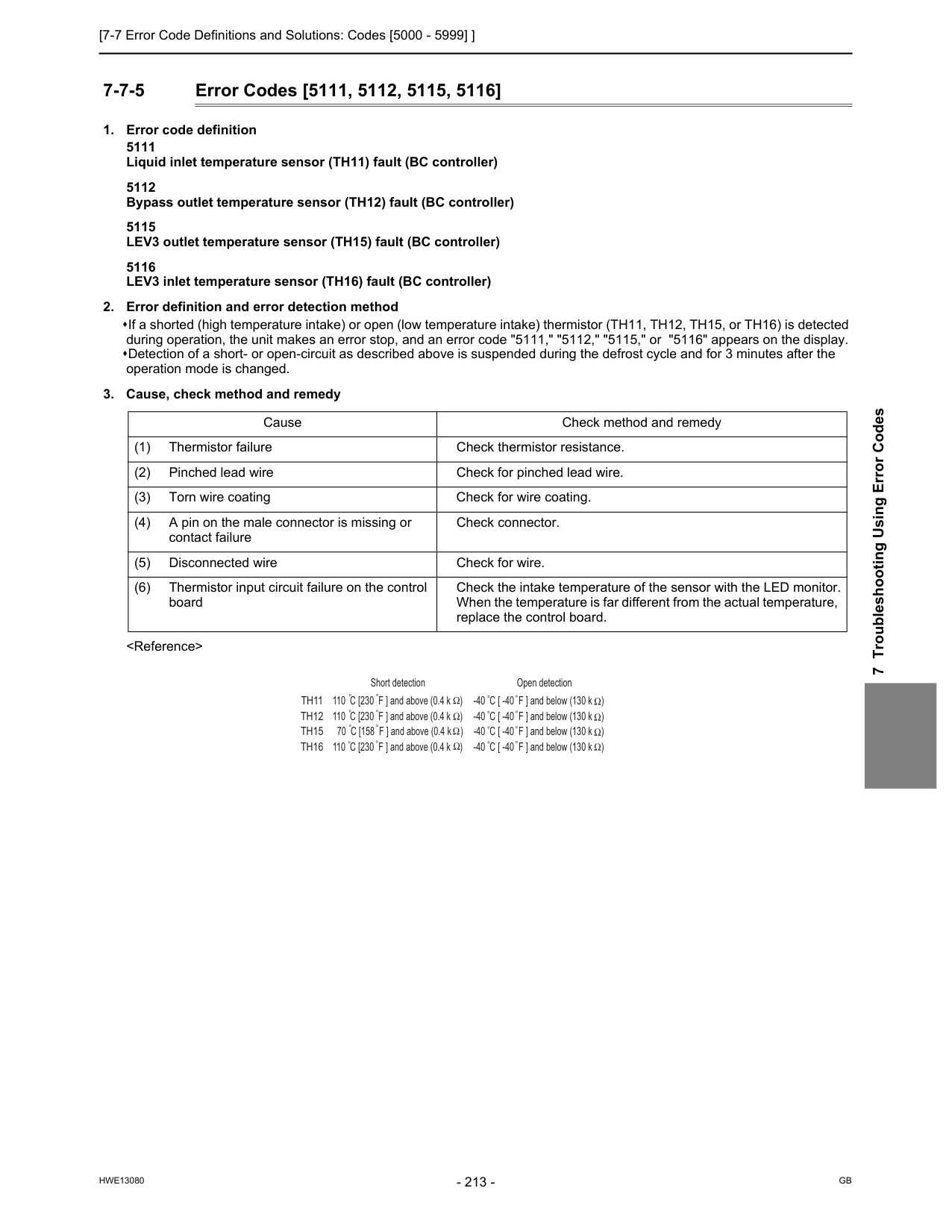
[7-7 Error Code Definitions and Solutions: Codes [5000 - 5999] ]
Hwe13080
Gb
7 Troubleshooting Using Error Codes 7-7-5 Error Codes [5111, 5112, 5115, 5116]Th11
Th12
Th15
Th16
Open detection -40 C [ -40 F ] and below (130 k ) -40 C [ -40 F ] and below (130 k ) -40 C [ -40 F ] and below (130 k ) -40 C [ -40 F ] and below (130 k ) Short detection 110 C [230 F ] and above (0.4 k ) 110 C [230 F ] and above (0.4 k ) 70 C [158 F ] and above (0.4 k ) 110 C [230 F ] and above (0.4 k )
[7-7 Error Code Definitions and Solutions: Codes [5000 - 5999] ]
Hwe13080
Gb
7-7-6 Error Code [5201]
[7-7 Error Code Definitions and Solutions: Codes [5000 - 5999] ]
Hwe13080
Gb
7 Troubleshooting Using Error Codes 7-7-8 Error Code [5301] Detail Code 115 (TKMU)
[7-7 Error Code Definitions and Solutions: Codes [5000 - 5999] ]
Hwe13080
Gb
7-7-10 Error Code [5301] Detail Code 116 (TKMU)(Tkmu)
[8-10-2 Checking the Inverter Board Error Detection Circuit](page 290) [8-10-4 Checking the Inverter for Damage at No-Load](page 290) [8-10-5 Checking the Inverter for Damage during Compressor Operation](page 291)(Ykmu)
[8-11-2 Checking the Inverter Board Error Detection Circuit](page 300) [8-11-4 Checking the Inverter for Damage at No-Load](page 300) [8-11-5 Checking the Inverter for Damage during Compressor Operation](page 301) (2) Compressor failure Refer to the following page(s).(Tkmu)
[8-10-3 Checking the Compressor for Ground Fault and Coil Resistance Prob- lems](page 290)(Ykmu)
[8-11-3 Checking the Compressor for Ground Fault and Coil Resistance Prob- lems](page 300)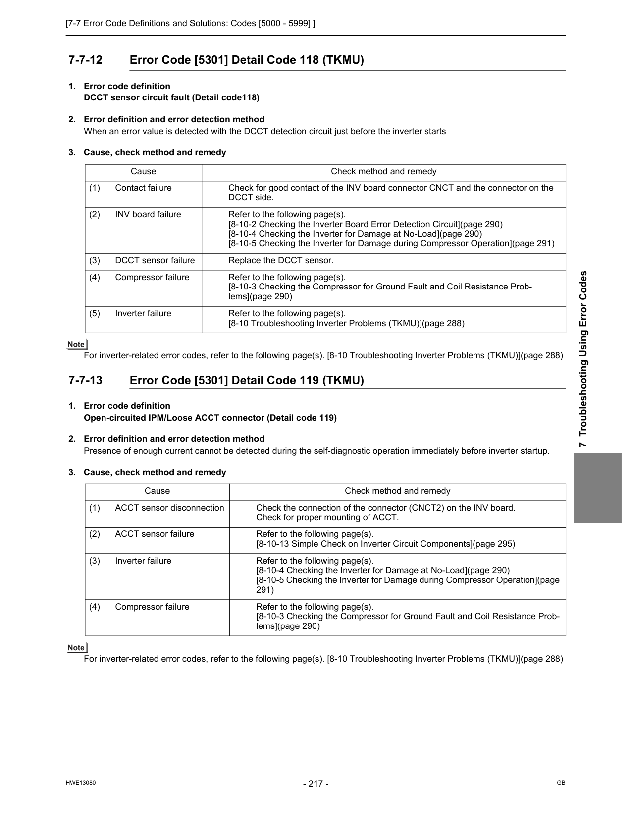
[7-7 Error Code Definitions and Solutions: Codes [5000 - 5999] ]
Hwe13080
Gb
7 Troubleshooting Using Error Codes 7-7-12 Error Code [5301] Detail Code 118 (TKMU)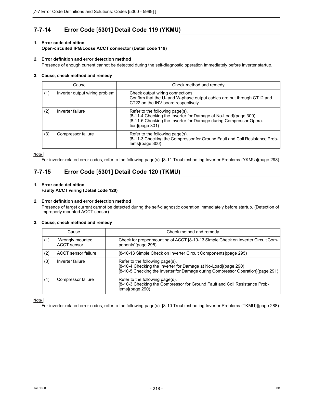
[7-7 Error Code Definitions and Solutions: Codes [5000 - 5999] ]
Hwe13080
Gb
7-7-14 Error Code [5301] Detail Code 119 (YKMU)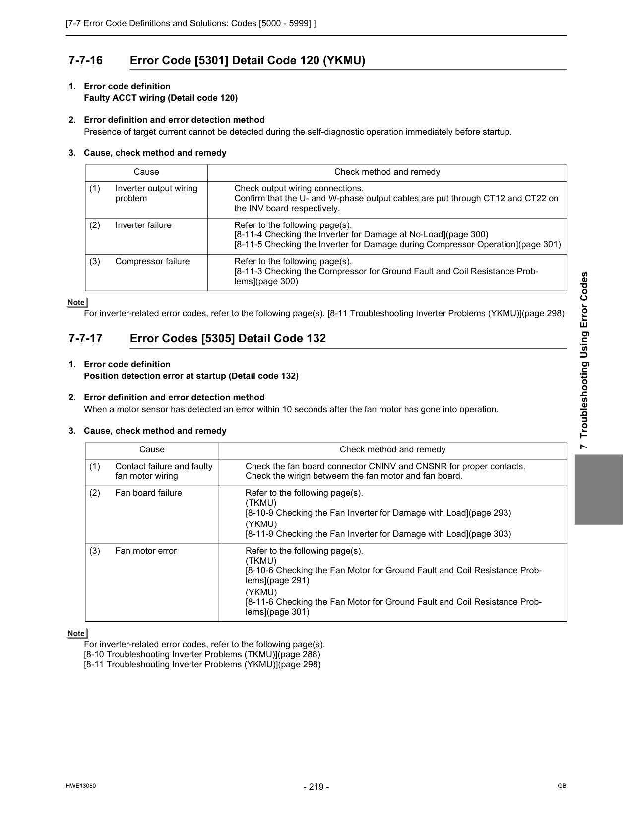
[7-7 Error Code Definitions and Solutions: Codes [5000 - 5999] ]
Hwe13080
Gb
7 Troubleshooting Using Error Codes 7-7-16 Error Code [5301] Detail Code 120 (YKMU)(Tkmu)
[8-10-9 Checking the Fan Inverter for Damage with Load](page 293)(Ykmu)
[8-11-9 Checking the Fan Inverter for Damage with Load](page 303) (3) Fan motor error Refer to the following page(s).(Tkmu)
[8-10-6 Checking the Fan Motor for Ground Fault and Coil Resistance Prob- lems](page 291)(Ykmu)
[8-11-6 Checking the Fan Motor for Ground Fault and Coil Resistance Prob- lems](page 301)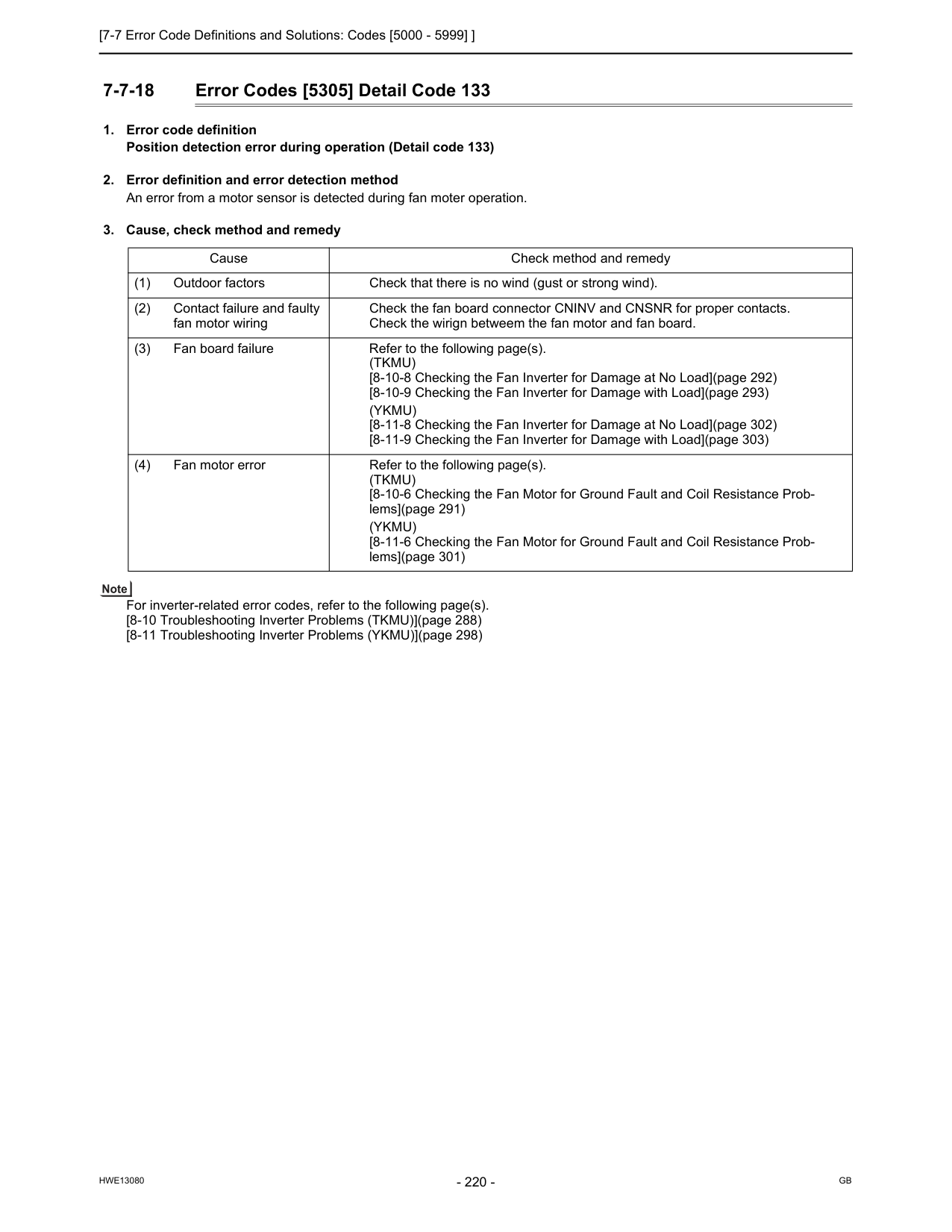
[7-7 Error Code Definitions and Solutions: Codes [5000 - 5999] ]
Hwe13080
Gb
7-7-18 Error Codes [5305] Detail Code 133(Tkmu)
[8-10-8 Checking the Fan Inverter for Damage at No Load](page 292) [8-10-9 Checking the Fan Inverter for Damage with Load](page 293)(Ykmu)
[8-11-8 Checking the Fan Inverter for Damage at No Load](page 302) [8-11-9 Checking the Fan Inverter for Damage with Load](page 303) (4) Fan motor error Refer to the following page(s).(Tkmu)
[8-10-6 Checking the Fan Motor for Ground Fault and Coil Resistance Prob- lems](page 291)(Ykmu)
[8-11-6 Checking the Fan Motor for Ground Fault and Coil Resistance Prob- lems](page 301)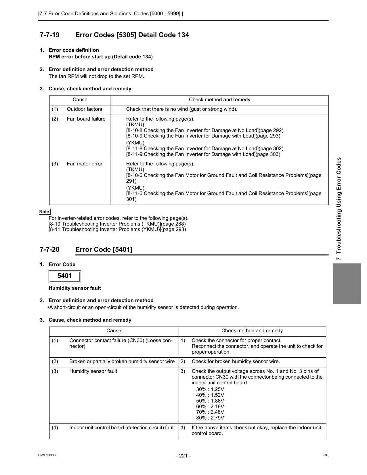
[7-7 Error Code Definitions and Solutions: Codes [5000 - 5999] ]
Hwe13080
Gb
7 Troubleshooting Using Error Codes 7-7-19 Error Codes [5305] Detail Code 134(Tkmu)
[8-10-8 Checking the Fan Inverter for Damage at No Load](page 292) [8-10-9 Checking the Fan Inverter for Damage with Load](page 293)(Ykmu)
[8-11-8 Checking the Fan Inverter for Damage at No Load](page 302) [8-11-9 Checking the Fan Inverter for Damage with Load](page 303) (3) Fan motor error Refer to the following page(s).(Tkmu)
[8-10-6 Checking the Fan Motor for Ground Fault and Coil Resistance Problems](page 291)(Ykmu)
[8-11-6 Checking the Fan Motor for Ground Fault and Coil Resistance Problems](page 301) 5401 Cause Check method and remedy (1) Connector contact failure (CN30) (Loose con- nector) 1) Check the connector for proper contact. Reconnect the connector, and operate the unit to check for proper operation. (2) Broken or partially broken humidity sensor wire 2) Check for broken humidity sensor wire. (3) Humidity sensor fault 3) Check the output voltage across No. 1 and No. 3 pins of connector CN30 with the connector being connected to the indoor unit control board.30% : 1.25V
40% : 1.52V
50% : 1.88V
60% : 2.19V
70% : 2.48V
80% : 2.79V
(4) Indoor unit control board (detection circuit) fault 4) If the above items check out okay, replace the indoor unit control board.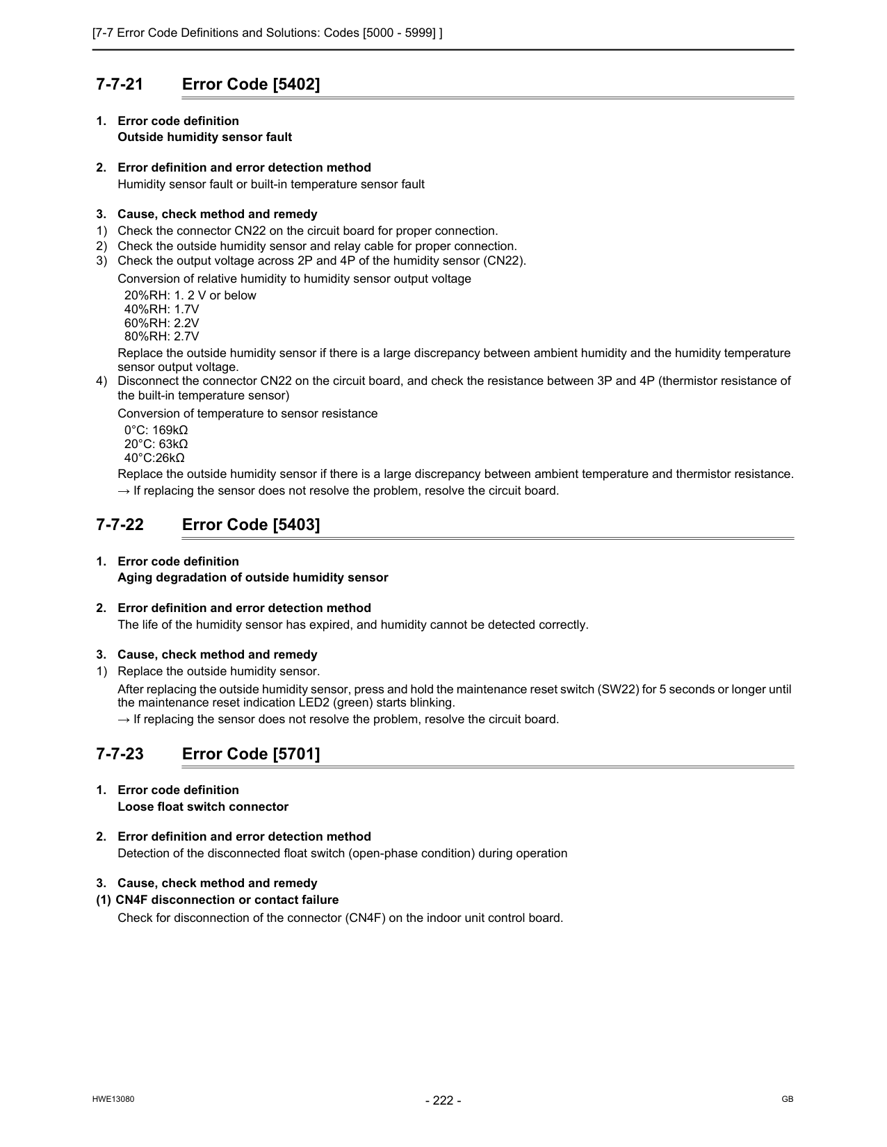
[7-7 Error Code Definitions and Solutions: Codes [5000 - 5999] ]
Hwe13080
Gb
7-7-21 Error Code [5402]40%Rh: 1.7V
60%Rh: 2.2V
80%Rh: 2.7V
Replace the outside humidity sensor if there is a large discrepancy between ambient humidity and the humidity temperature sensor output voltage. 4) Disconnect the connector CN22 on the circuit board, and check the resistance between 3P and 4P (thermistor resistance of the built-in temperature sensor) Conversion of temperature to sensor resistance 0°C: 169kΩ 20°C: 63kΩ 40°C:26kΩ Replace the outside humidity sensor if there is a large discrepancy between ambient temperature and thermistor resistance. → If replacing the sensor does not resolve the problem, resolve the circuit board. 7-7-22 Error Code [5403]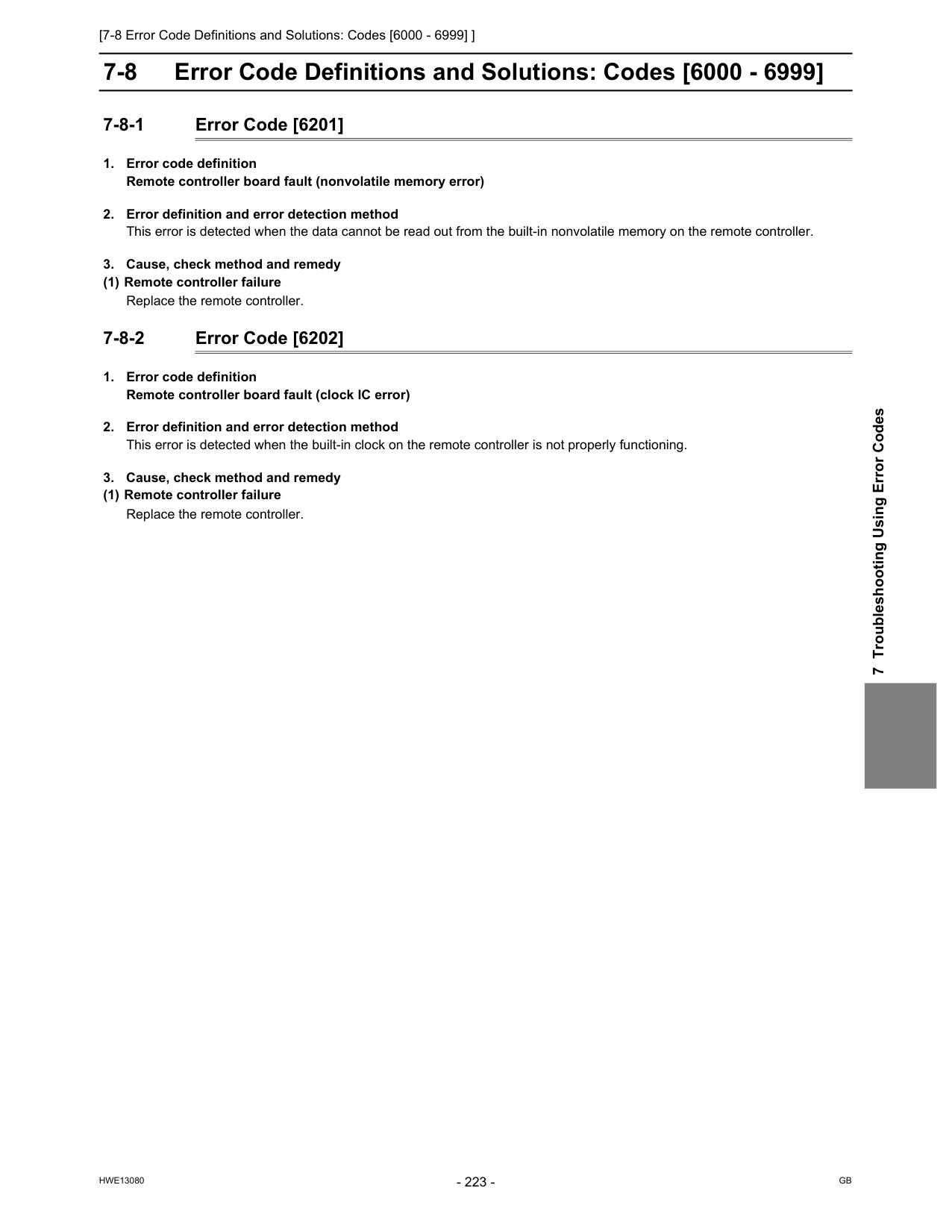
[7-8 Error Code Definitions and Solutions: Codes [6000 - 6999] ]
Hwe13080
Gb
7 Troubleshooting Using Error Codes 7-8 Error Code Definitions and Solutions: Codes [6000 - 6999] 7-8-1 Error Code [6201]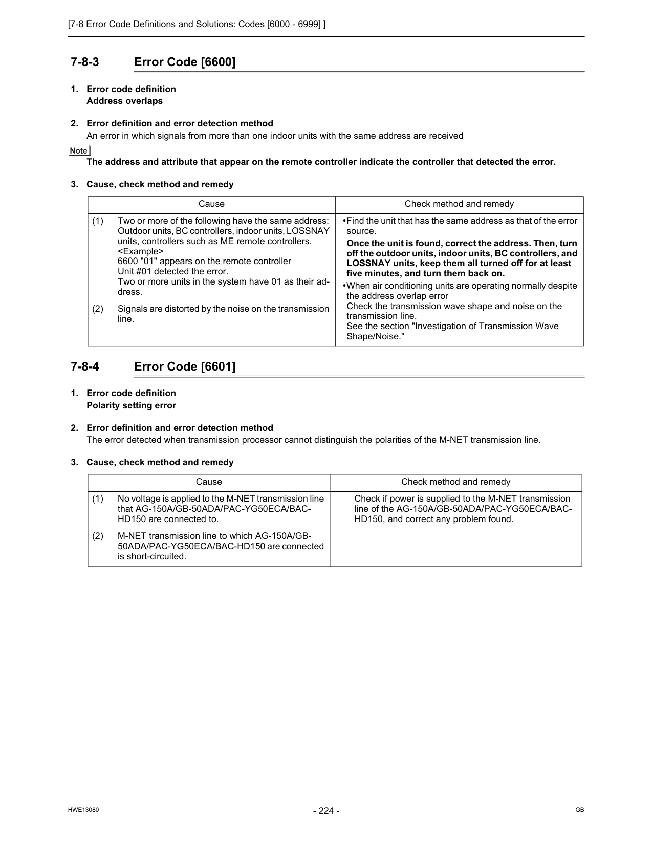
[7-8 Error Code Definitions and Solutions: Codes [6000 - 6999] ]
Hwe13080
Gb
7-8-3 Error Code [6600]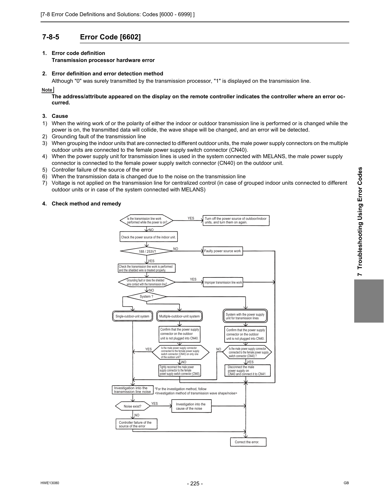
[7-8 Error Code Definitions and Solutions: Codes [6000 - 6999] ]
Hwe13080
Gb
7 Troubleshooting Using Error Codes 7-8-5 Error Code [6602]No
Tightly reconnect the male power supply connector to the female power supply switch connector (CN40).Yes
Yes
Yes
Yes
Yes
Yes
No
No
No
No
Is the transmission line work performed while the power is on? Check the power source of the indoor unit.188 / 253V?
Check the transmission line work is performed and the shielded wire is treated properly. Grounding fault or does the shielded wire contact with the transmission line? System ? Faulty power source work Improper transmission line work Turn off the power source of outdoor/indoor units, and turn them on again.No
Investigation into the transmission line noise Noise exist? Controller failure of the source of the error *For the investigation method, follow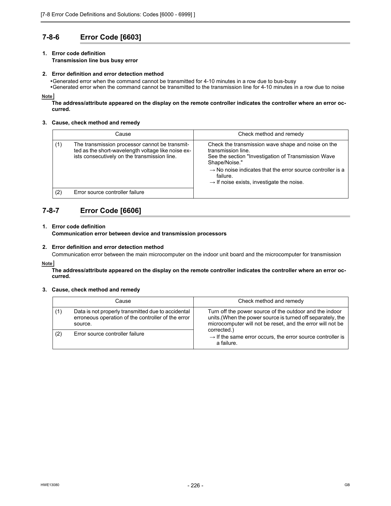
[7-8 Error Code Definitions and Solutions: Codes [6000 - 6999] ]
Hwe13080
Gb
7-8-6 Error Code [6603]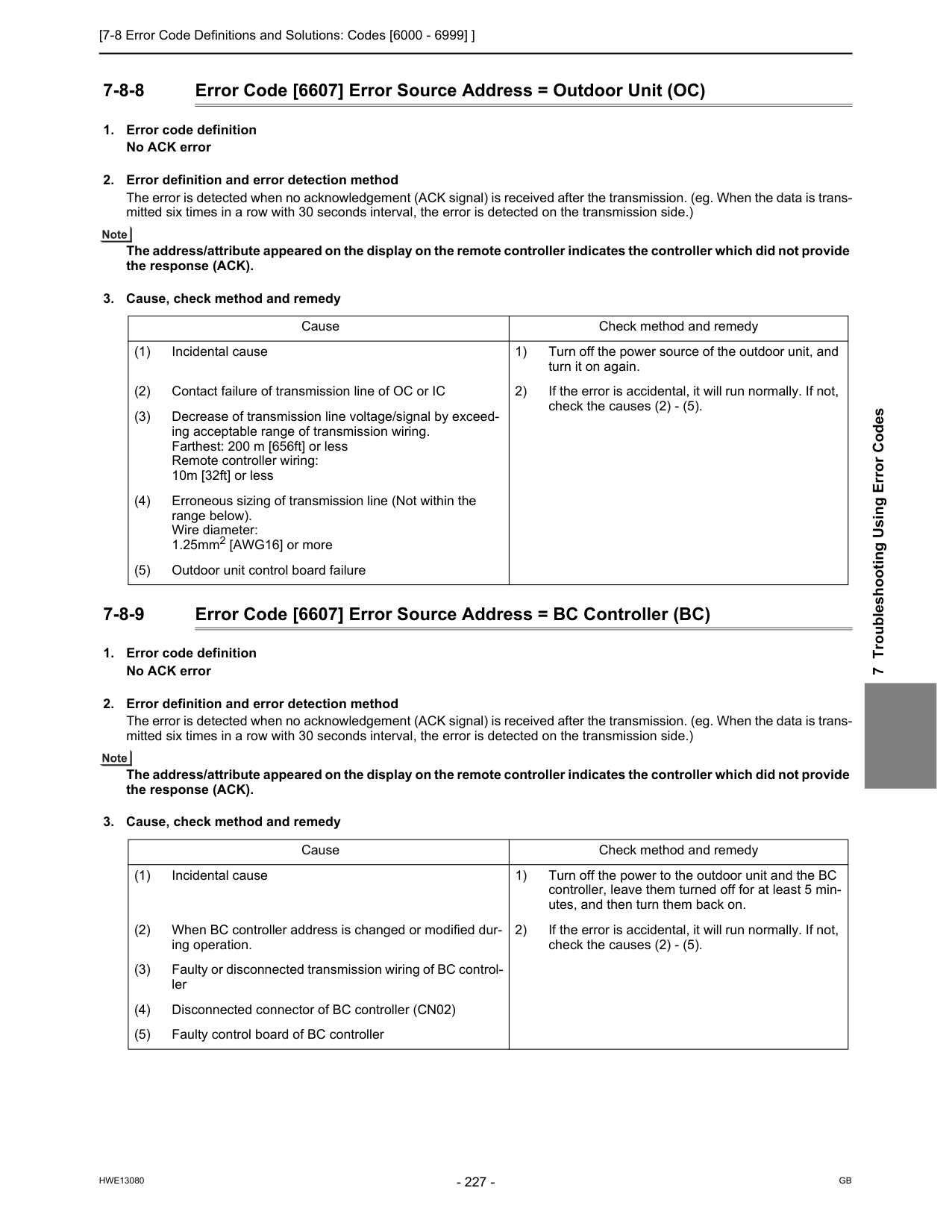
[7-8 Error Code Definitions and Solutions: Codes [6000 - 6999] ]
Hwe13080
Gb
7 Troubleshooting Using Error Codes 7-8-8 Error Code [6607] Error Source Address = Outdoor Unit (OC)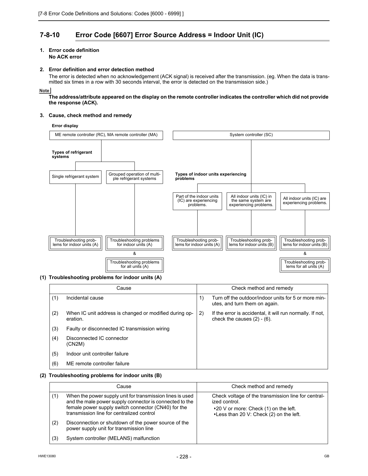
[7-8 Error Code Definitions and Solutions: Codes [6000 - 6999] ]
Hwe13080
Gb
7-8-10 Error Code [6607] Error Source Address = Indoor Unit (IC)(Cn2M)
(5) Indoor unit controller failure (6) ME remote controller failure Cause Check method and remedy (1) When the power supply unit for transmission lines is used and the male power supply connector is connected to the female power supply switch connector (CN40) for the transmission line for centralized control Check voltage of the transmission line for central- ized control. 20 V or more: Check (1) on the left. Less than 20 V: Check (2) on the left. (2) Disconnection or shutdown of the power source of the power supply unit for transmission line (3) System controller (MELANS) malfunction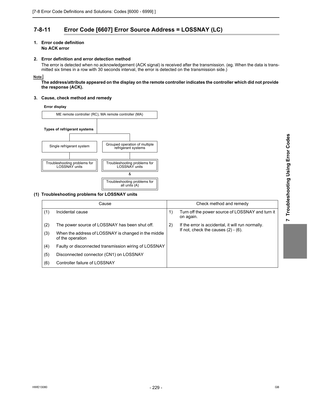
[7-8 Error Code Definitions and Solutions: Codes [6000 - 6999] ]
Hwe13080
Gb
7 Troubleshooting Using Error Codes 7-8-11 Error Code [6607] Error Source Address = LOSSNAY (LC)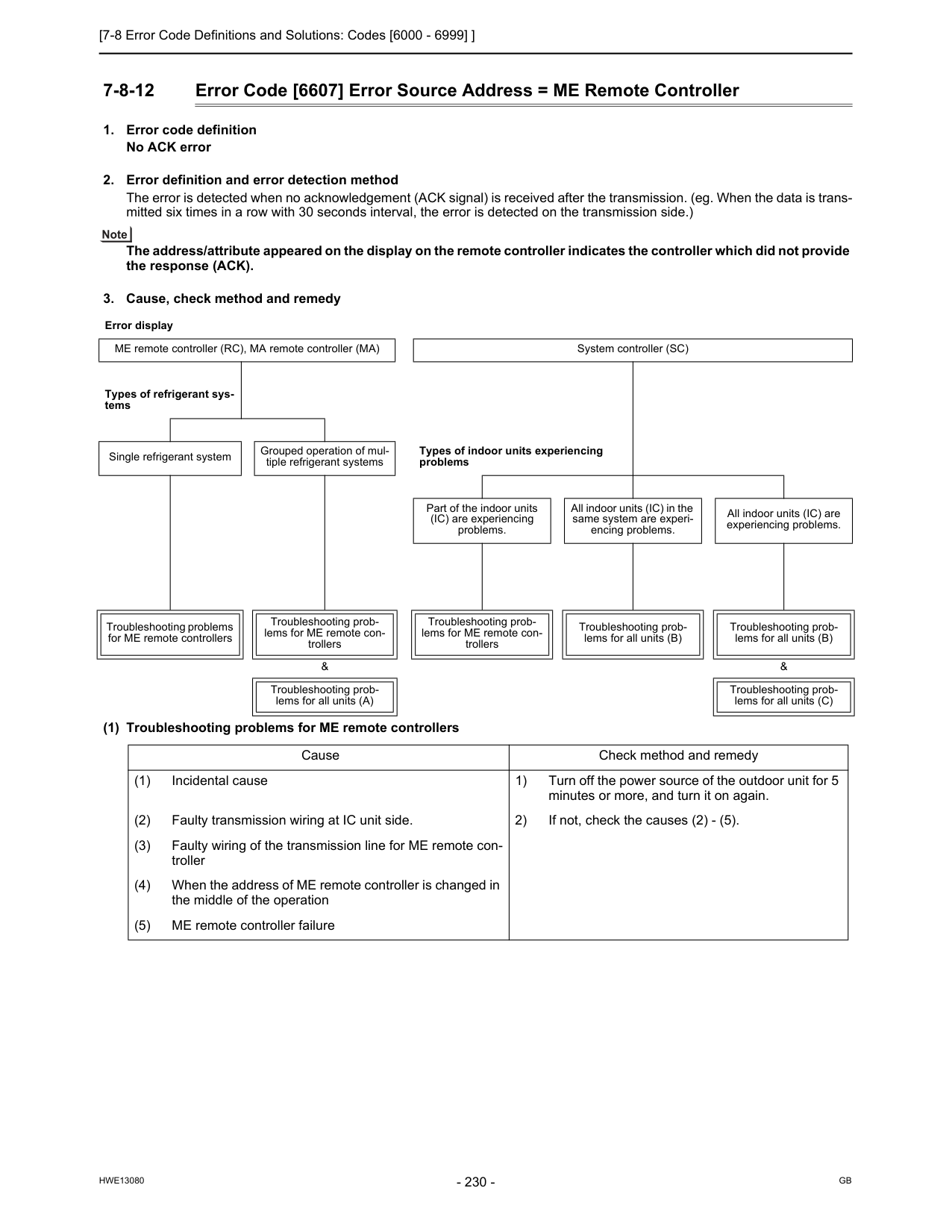
[7-8 Error Code Definitions and Solutions: Codes [6000 - 6999] ]
Hwe13080
Gb
7-8-12 Error Code [6607] Error Source Address = ME Remote Controller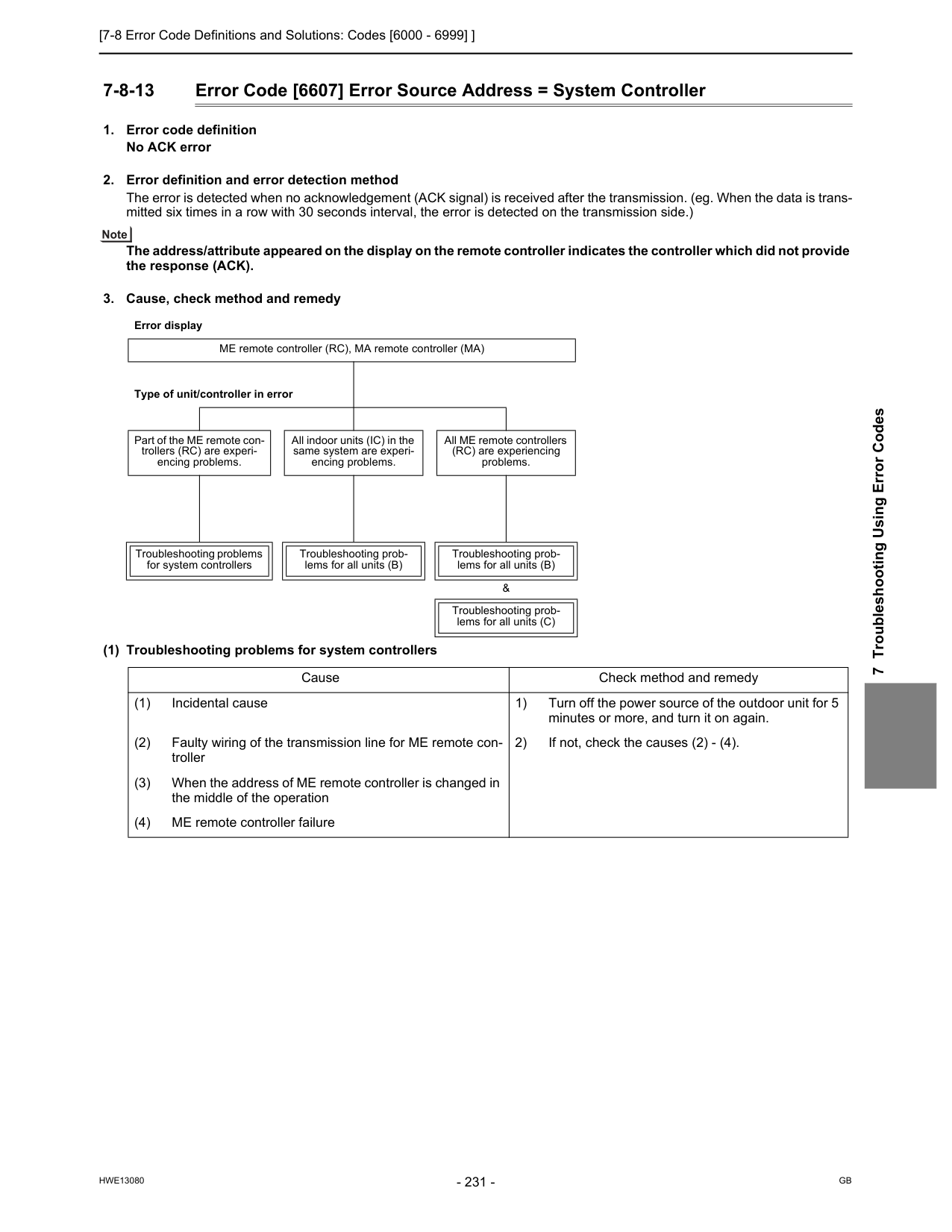
[7-8 Error Code Definitions and Solutions: Codes [6000 - 6999] ]
Hwe13080
Gb
7 Troubleshooting Using Error Codes 7-8-13 Error Code [6607] Error Source Address = System Controller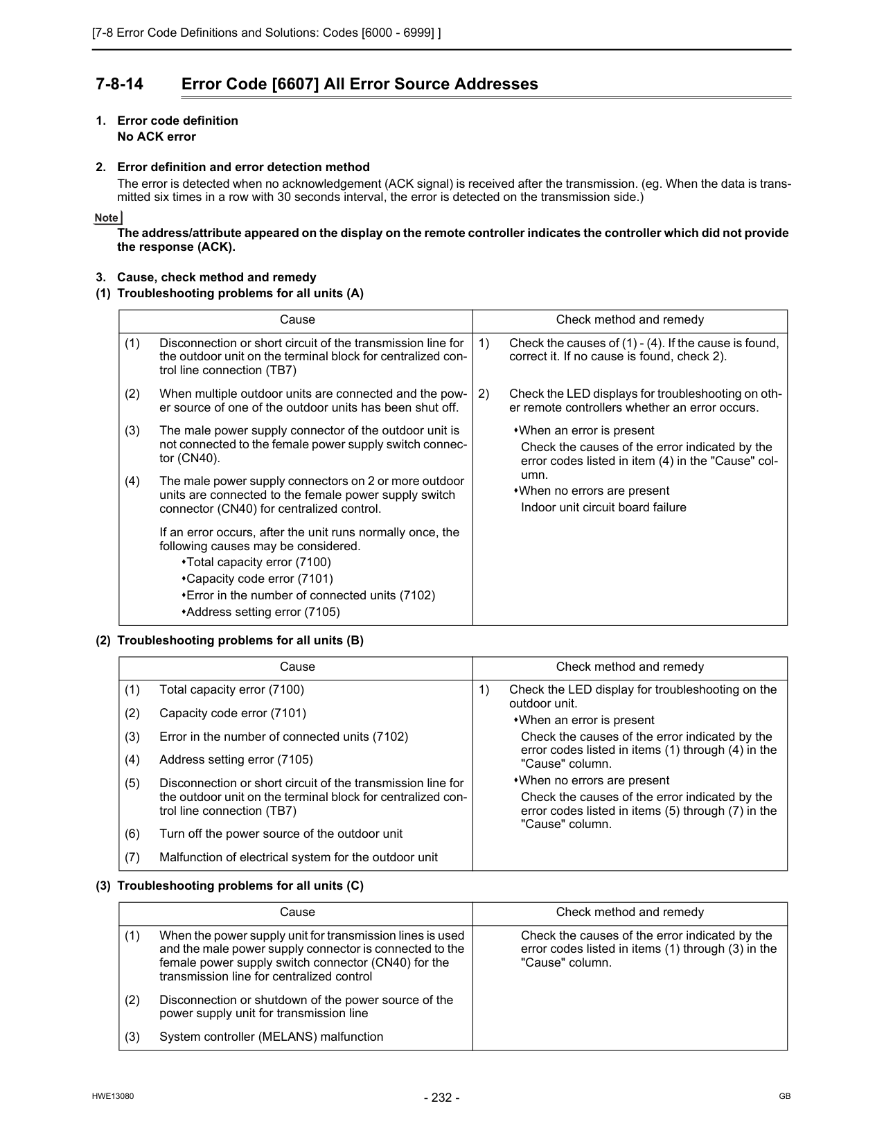
[7-8 Error Code Definitions and Solutions: Codes [6000 - 6999] ]
Hwe13080
Gb
7-8-14 Error Code [6607] All Error Source Addresses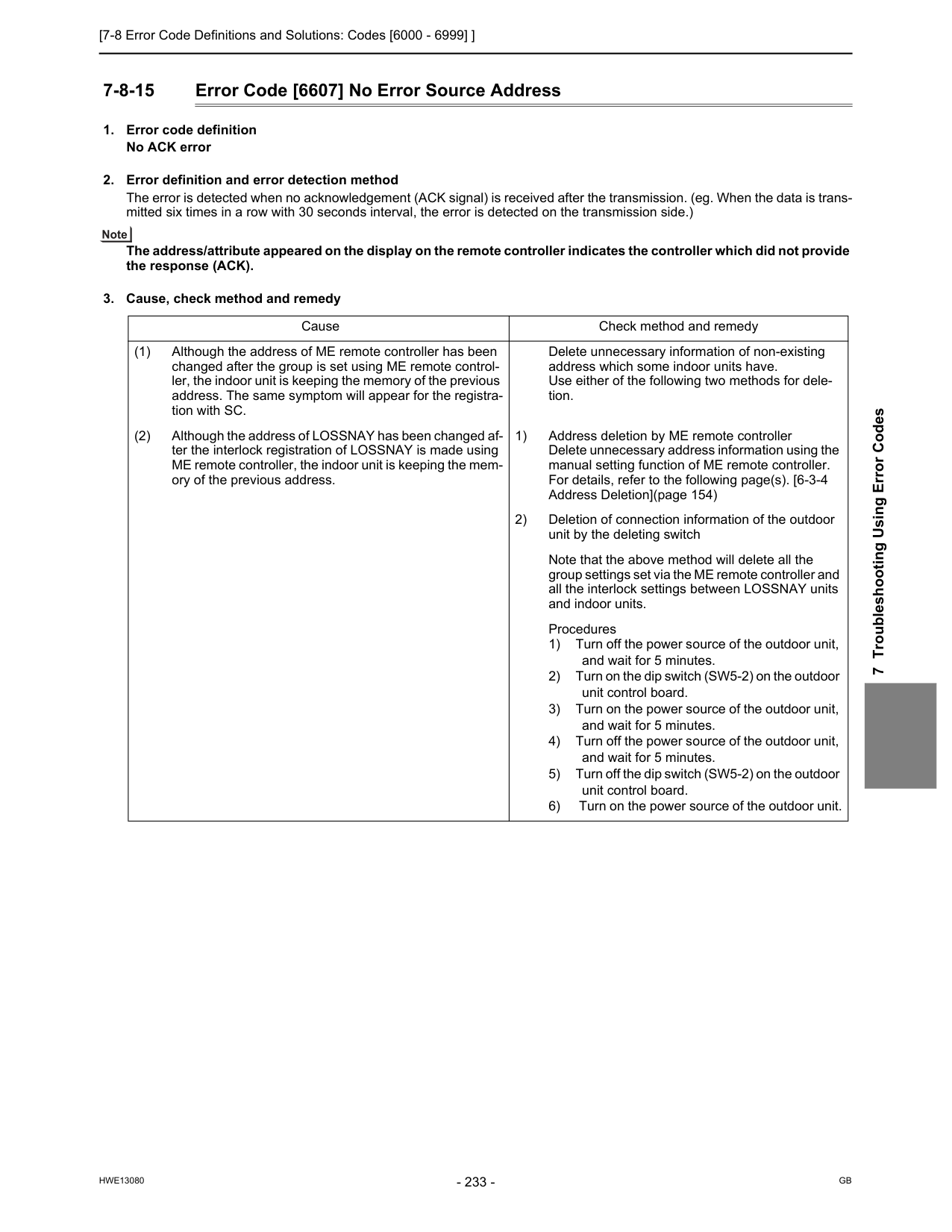
[7-8 Error Code Definitions and Solutions: Codes [6000 - 6999] ]
Hwe13080
Gb
7 Troubleshooting Using Error Codes 7-8-15 Error Code [6607] No Error Source Address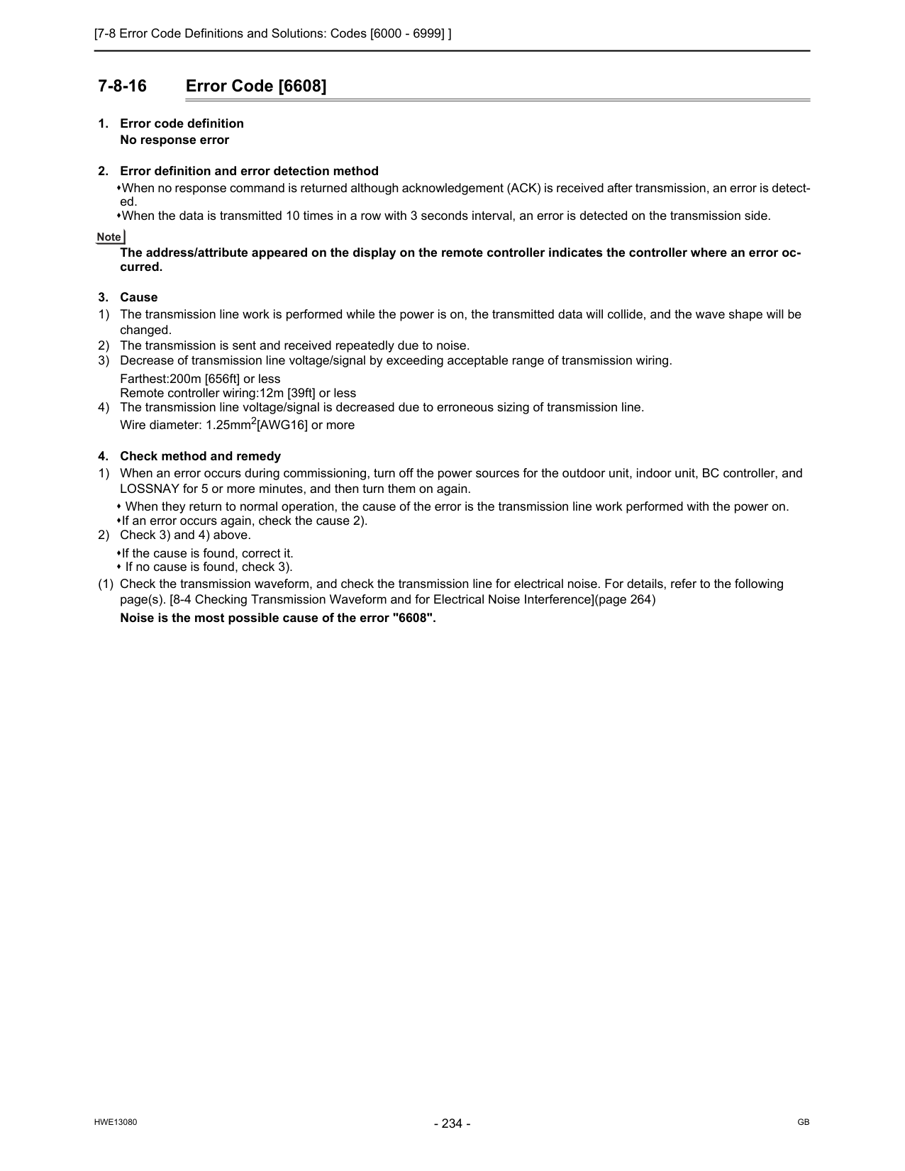
[7-8 Error Code Definitions and Solutions: Codes [6000 - 6999] ]
Hwe13080
Gb
7-8-16 Error Code [6608]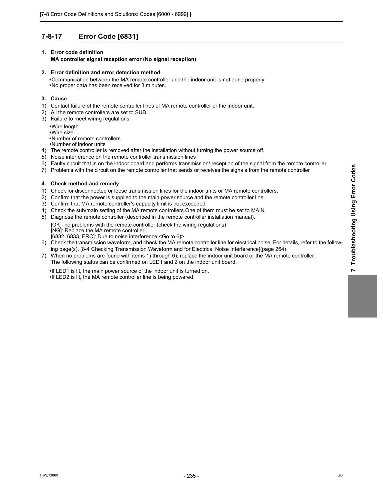
[7-8 Error Code Definitions and Solutions: Codes [6000 - 6999] ]
Hwe13080
Gb
7 Troubleshooting Using Error Codes 7-8-17 Error Code [6831]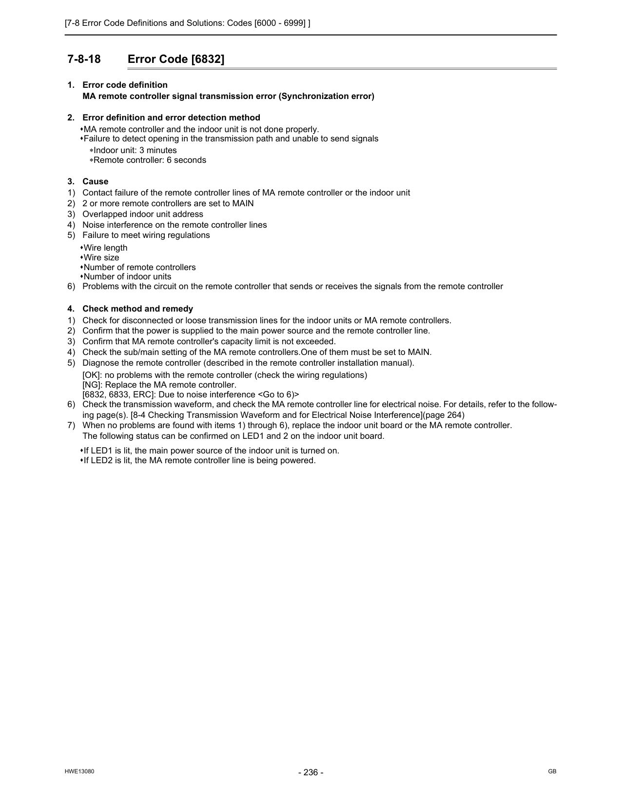
[7-8 Error Code Definitions and Solutions: Codes [6000 - 6999] ]
Hwe13080
Gb
7-8-18 Error Code [6832]
[7-8 Error Code Definitions and Solutions: Codes [6000 - 6999] ]
Hwe13080
Gb
7 Troubleshooting Using Error Codes 7-8-19 Error Code [6833]
[7-8 Error Code Definitions and Solutions: Codes [6000 - 6999] ]
Hwe13080
Gb
7-8-20 Error Code [6834]
[7-9 Error Code Definitions and Solutions: Codes [7000 - 7999] ]
Hwe13080
Gb
7 Troubleshooting Using Error Codes 7-9 Error Code Definitions and Solutions: Codes [7000 - 7999] 7-9-1 Error Code [7100]Sw5
Off
On
Off
Off
On
On
Off
Off
3 4 5 6
[7-9 Error Code Definitions and Solutions: Codes [7000 - 7999] ]
Hwe13080
Gb
7-9-2 Error Code [7101]Sw5
Off
On
Off
Off
On
On
Off
Off
3 4 5 6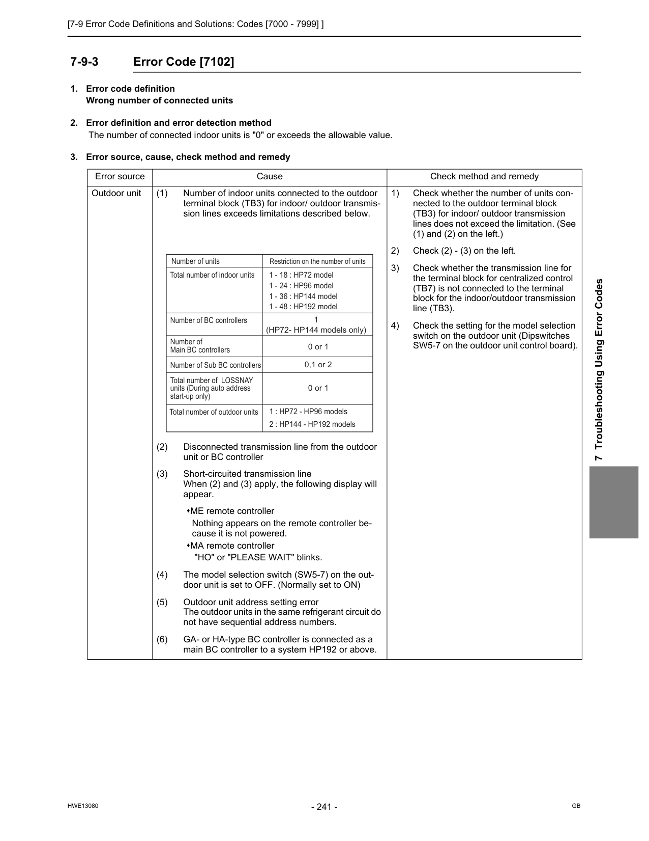
[7-9 Error Code Definitions and Solutions: Codes [7000 - 7999] ]
Hwe13080
Gb
7 Troubleshooting Using Error Codes 7-9-3 Error Code [7102]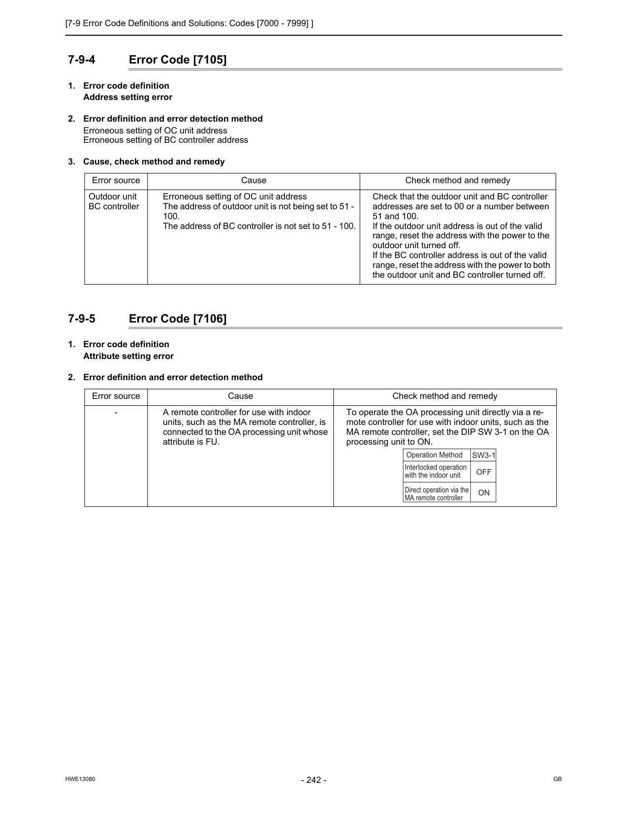
[7-9 Error Code Definitions and Solutions: Codes [7000 - 7999] ]
Hwe13080
Gb
7-9-4 Error Code [7105]Sw3-1
Off
On
Interlocked operation with the indoor unit Operation Method Direct operation via the MA remote controller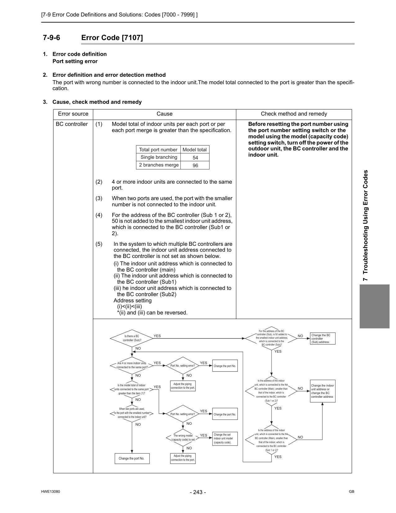
[7-9 Error Code Definitions and Solutions: Codes [7000 - 7999] ]
Hwe13080
Gb
7 Troubleshooting Using Error Codes 7-9-6 Error Code [7107]Yes
Yes
No
Yes
Yes
No
For the address of the BC controller (Sub), is 50 added to the smallest indoor unit address, which is connected to the BC controller (Sub)? Is the address of the indoor unit, which is connected to the the BC controller (Main) ,smaller than that of the indoor, which is connected to the BC controller (Sub 1 or 2)?Yes
Yes
Is the address of the indoor unit, which is connected to the the BC controller (Main), smaller than that of the indoor, which is connected to the BC controller (Sub 1 or 2)?Yes
No
No
No
No
No
Change the port No.No
Change the BC controller (Sub) address.No
No
Change the indoor unit address or change the BC controller addressYes
Change the port No.Yes
Change the set indoor unit model (capacity code). Port No. setting error? Port No. setting error? The wrong model (capacity code) is set. Adjust the piping connection to the port. Adjust the piping connection to the port.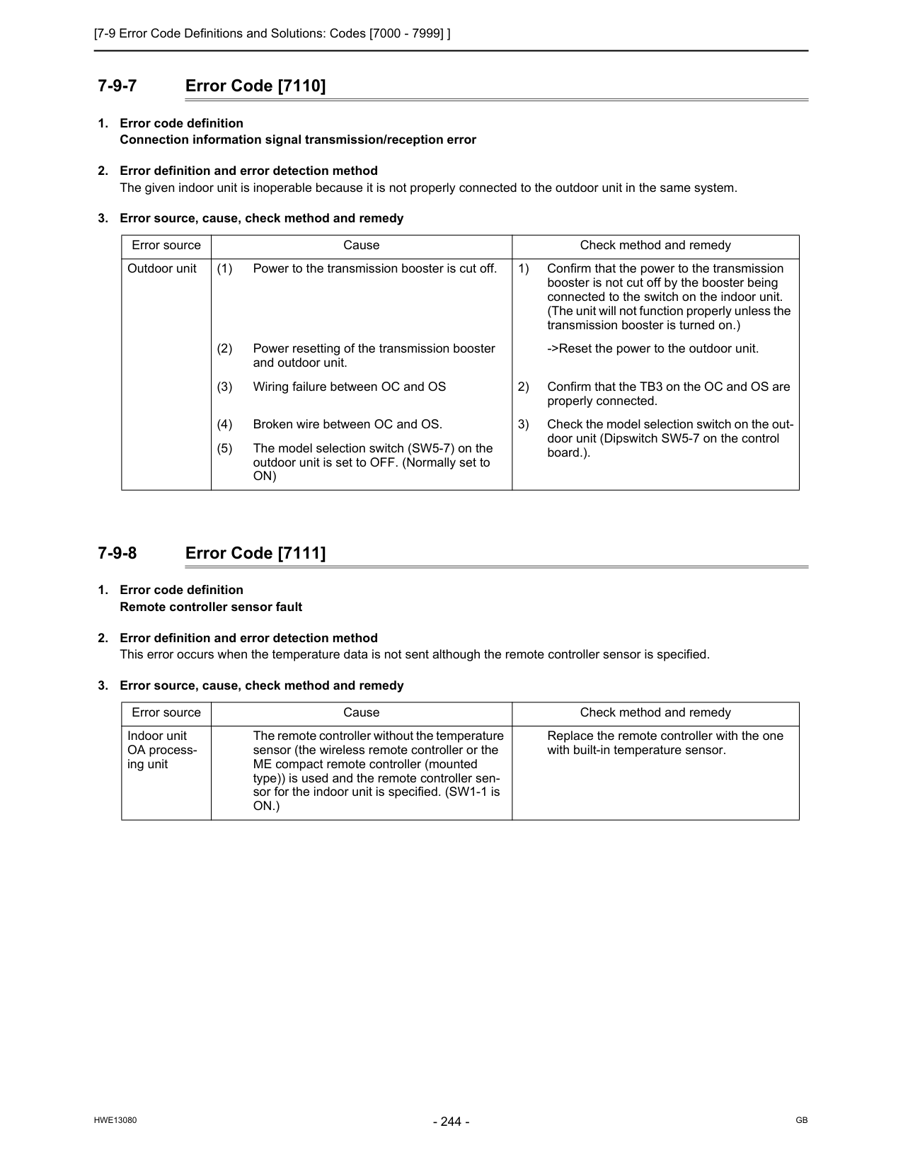
[7-9 Error Code Definitions and Solutions: Codes [7000 - 7999] ]
Hwe13080
Gb
7-9-7 Error Code [7110]On)
Error source Cause Check method and remedy Indoor unit OA process- ing unit The remote controller without the temperature sensor (the wireless remote controller or the ME compact remote controller (mounted type)) is used and the remote controller sen- sor for the indoor unit is specified. (SW1-1 isOn.)
Replace the remote controller with the one with built-in temperature sensor.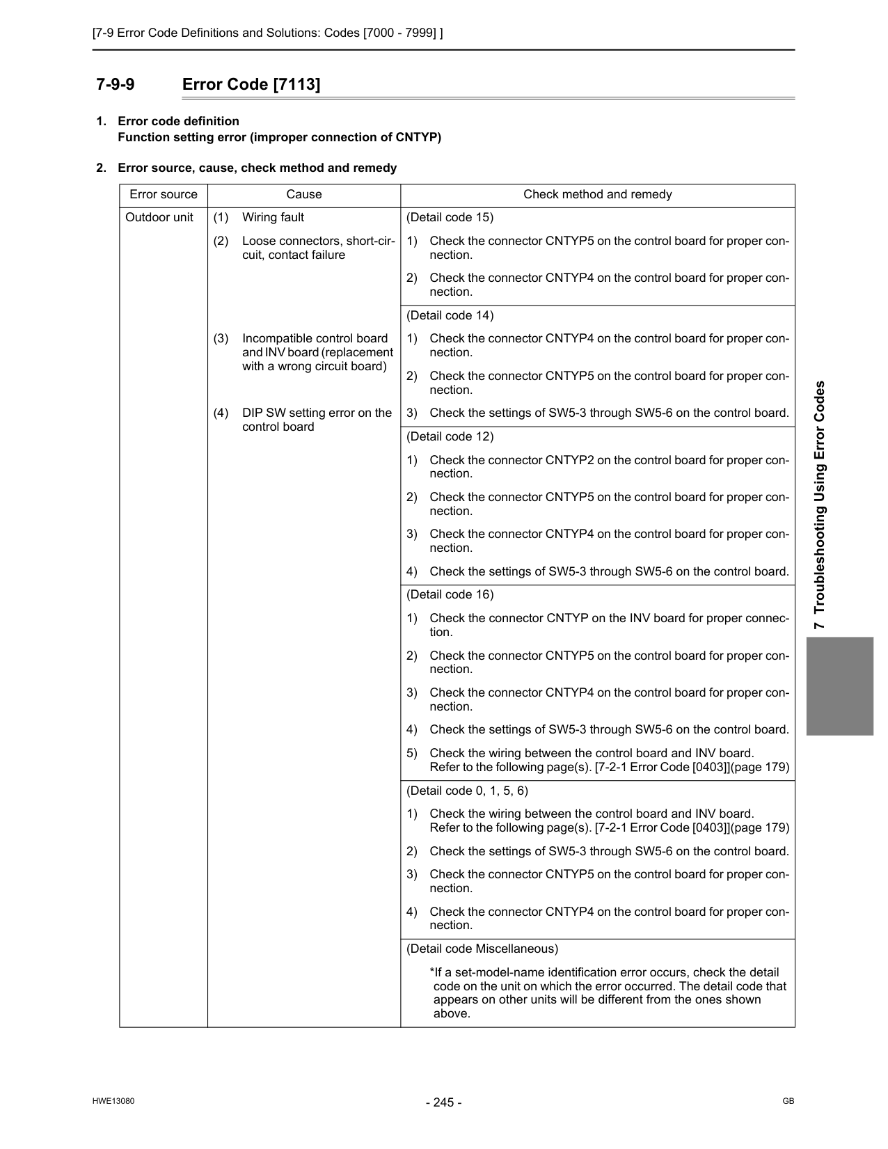
[7-9 Error Code Definitions and Solutions: Codes [7000 - 7999] ]
Hwe13080
Gb
7 Troubleshooting Using Error Codes 7-9-9 Error Code [7113]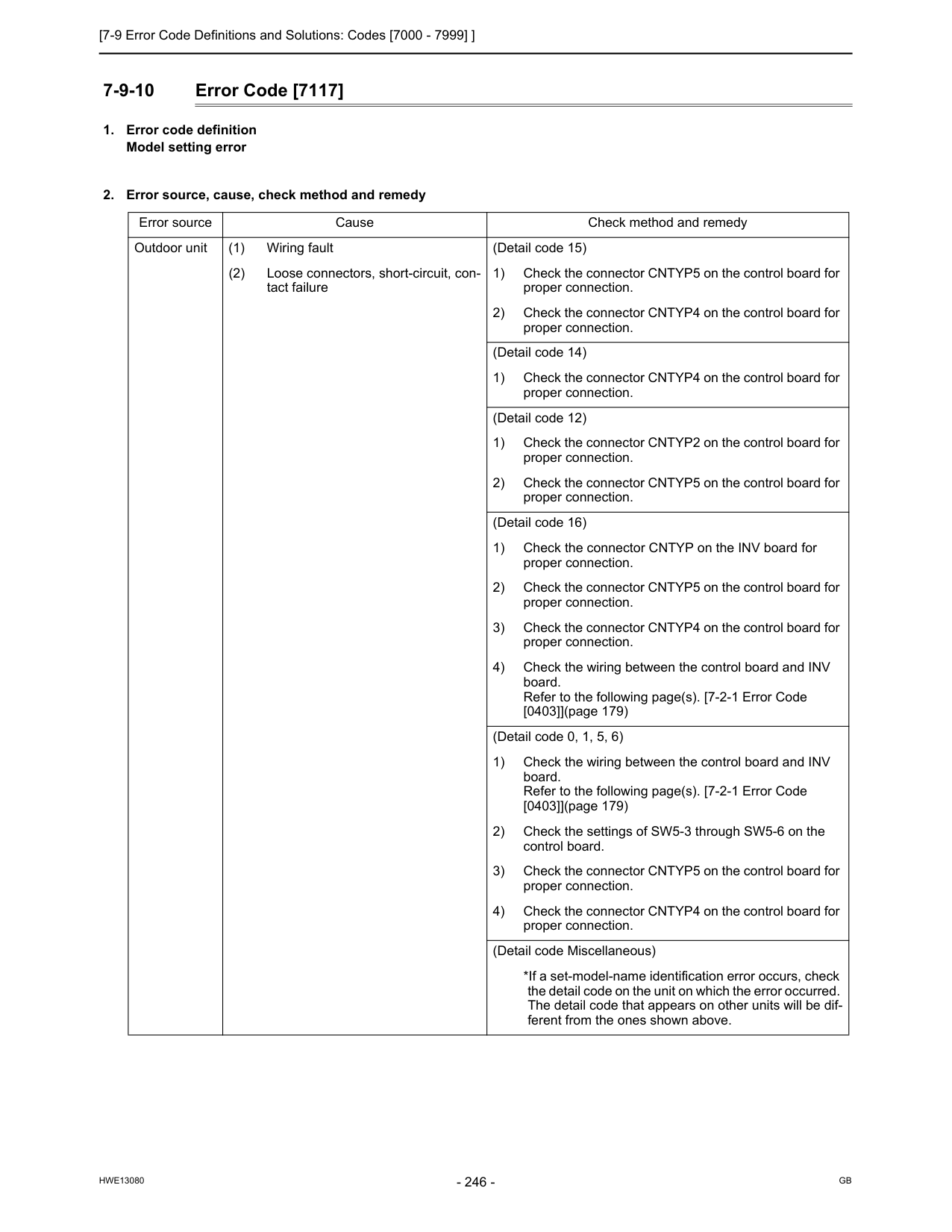
[7-9 Error Code Definitions and Solutions: Codes [7000 - 7999] ]
Hwe13080
Gb
7-9-10 Error Code [7117]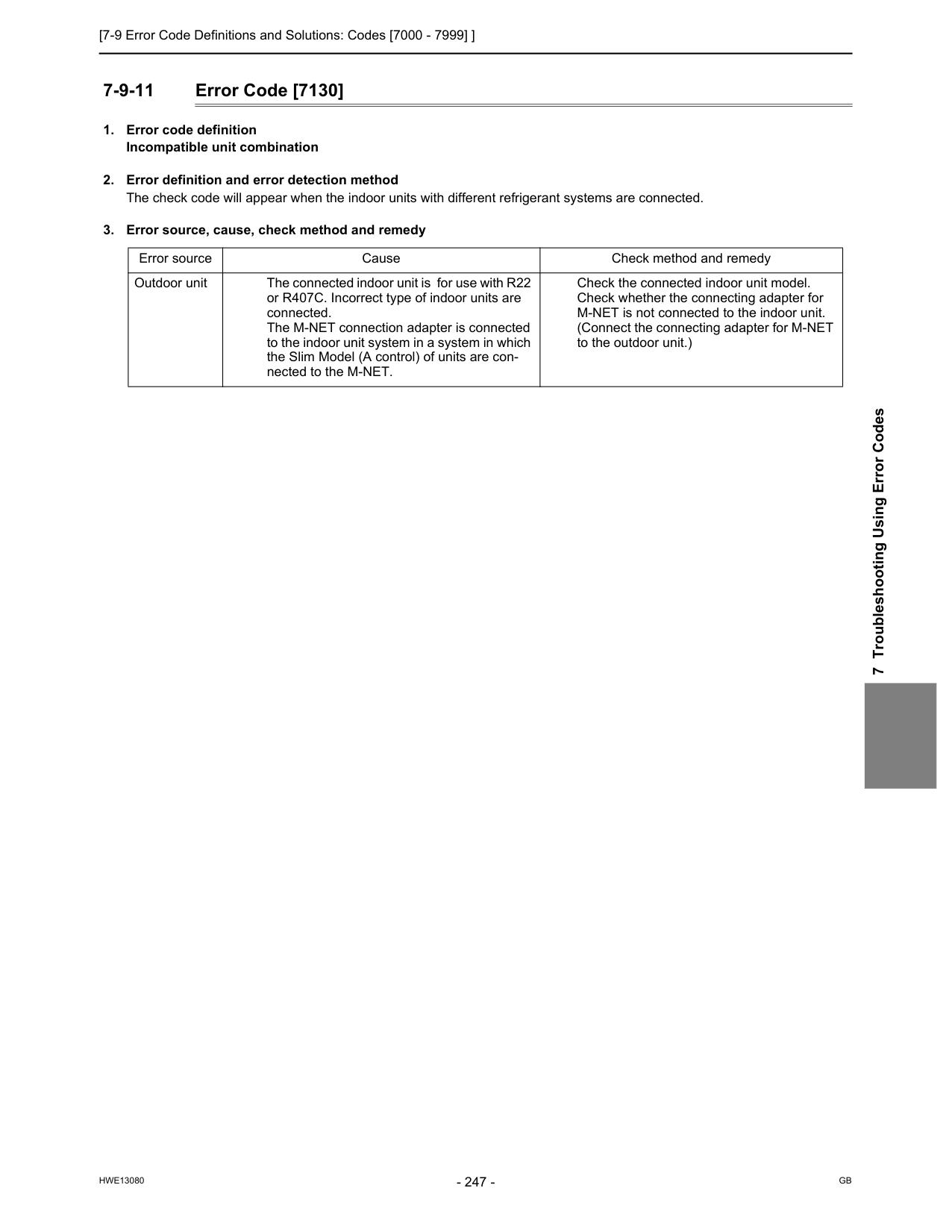
[7-9 Error Code Definitions and Solutions: Codes [7000 - 7999] ]
Hwe13080
Gb
7 Troubleshooting Using Error Codes 7-9-11 Error Code [7130]
[7-9 Error Code Definitions and Solutions: Codes [7000 - 7999] ]
Hwe13080
Gb
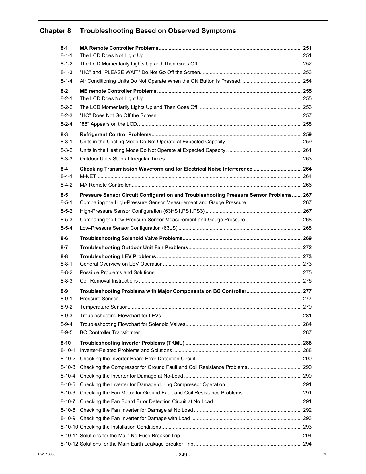
Hwe13080
Gb
Chapter 8 Troubleshooting Based on Observed Symptoms 8-1 MA Remote Controller Problems..................................................................................................... 251 8-1-1 The LCD Does Not Light Up. .............................................................................................................. 251 8-1-2 The LCD Momentarily Lights Up and Then Goes Off. ........................................................................ 252 8-1-3 "HO" and "PLEASE WAIT" Do Not Go Off the Screen. ...................................................................... 253 8-1-4 Air Conditioning Units Do Not Operate When the ON Button Is Pressed........................................... 254 8-2 ME remote Controller Problems...................................................................................................... 255 8-2-1 The LCD Does Not Light Up. .............................................................................................................. 255 8-2-2 The LCD Momentarily Lights Up and Then Goes Off. ........................................................................ 256 8-2-3 "HO" Does Not Go Off the Screen. ..................................................................................................... 257 8-2-4 "88" Appears on the LCD.................................................................................................................... 258 8-3 Refrigerant Control Problems.......................................................................................................... 259 8-3-1 Units in the Cooling Mode Do Not Operate at Expected Capacity...................................................... 259 8-3-2 Units in the Heating Mode Do Not Operate at Expected Capacity. .................................................... 261 8-3-3 Outdoor Units Stop at Irregular Times. ............................................................................................... 263 8-4 Checking Transmission Waveform and for Electrical Noise Interference .................................. 264 8-4-1 M-NET................................................................................................................................................. 264 8-4-2 MA Remote Controller ........................................................................................................................ 266 8-5 Pressure Sensor Circuit Configuration and Troubleshooting Pressure Sensor Problems....... 267 8-5-1 Comparing the High-Pressure Sensor Measurement and Gauge Pressure....................................... 267 8-5-2 High-Pressure Sensor Configuration (63HS1,PS1,PS3) .................................................................... 267 8-5-3 Comparing the Low-Pressure Sensor Measurement and Gauge Pressure........................................ 268 8-5-4 Low-Pressure Sensor Configuration (63LS) ....................................................................................... 268 8-6 Troubleshooting Solenoid Valve Problems.................................................................................... 269 8-7 Troubleshooting Outdoor Unit Fan Problems................................................................................ 272 8-8 Troubleshooting LEV Problems ...................................................................................................... 273 8-8-1 General Overview on LEV Operation.................................................................................................. 273 8-8-2 Possible Problems and Solutions ....................................................................................................... 275 8-8-3 Coil Removal Instructions ................................................................................................................... 276 8-9 Troubleshooting Problems with Major Components on BC Controller....................................... 277 8-9-1 Pressure Sensor ................................................................................................................................. 277 8-9-2 Temperature Sensor........................................................................................................................... 279 8-9-3 Troubleshooting Flowchart for LEVs................................................................................................... 281 8-9-4 Troubleshooting Flowchart for Solenoid Valves.................................................................................. 284 8-9-5 BC Controller Transformer.................................................................................................................. 287 8-10 Troubleshooting Inverter Problems (TKMU) .................................................................................. 288 8-10-1 Inverter-Related Problems and Solutions ........................................................................................... 288 8-10-2 Checking the Inverter Board Error Detection Circuit........................................................................... 290 8-10-3 Checking the Compressor for Ground Fault and Coil Resistance Problems...................................... 290 8-10-4 Checking the Inverter for Damage at No-Load ................................................................................... 290 8-10-5 Checking the Inverter for Damage during Compressor Operation...................................................... 291 8-10-6 Checking the Fan Motor for Ground Fault and Coil Resistance Problems ......................................... 291 8-10-7 Checking the Fan Board Error Detection Circuit at No Load .............................................................. 291 8-10-8 Checking the Fan Inverter for Damage at No Load ............................................................................ 292 8-10-9 Checking the Fan Inverter for Damage with Load .............................................................................. 293 8-10-10 Checking the Installation Conditions................................................................................................... 293 8-10-11 Solutions for the Main No-Fuse Breaker Trip...................................................................................... 294 8-10-12 Solutions for the Main Earth Leakage Breaker Trip............................................................................ 294
Hwe13080
Gb
8-10-13 Simple Check on Inverter Circuit Components................................................................................... 295 8-10-14 Troubleshooting Problems with Intelligent Power Module .................................................................. 296 8-10-15 Troubleshooting Problems with Diode Stack ...................................................................................... 297 8-11 Troubleshooting Inverter Problems (YKMU) .................................................................................. 298 8-11-1 Inverter-Related Problems and Solutions ........................................................................................... 298 8-11-2 Checking the Inverter Board Error Detection Circuit........................................................................... 300 8-11-3 Checking the Compressor for Ground Fault and Coil Resistance Problems...................................... 300 8-11-4 Checking the Inverter for Damage at No-Load ................................................................................... 300 8-11-5 Checking the Inverter for Damage during Compressor Operation...................................................... 301 8-11-6 Checking the Fan Motor for Ground Fault and Coil Resistance Problems ......................................... 301 8-11-7 Checking the Fan Board Error Detection Circuit at No Load .............................................................. 301 8-11-8 Checking the Fan Inverter for Damage at No Load ............................................................................ 302 8-11-9 Checking the Fan Inverter for Damage with Load .............................................................................. 303 8-11-10 Checking the Installation Conditions................................................................................................... 303 8-11-11 Solutions for the Main No-Fuse Breaker Trip...................................................................................... 304 8-11-12 Solutions for the Main Earth Leakage Breaker Trip............................................................................ 304 8-11-13 Simple Check on Inverter Circuit Components................................................................................... 305 8-11-14 Troubleshooting Problems with IGBT Module .................................................................................... 305 8-12 Control Circuit (TKMU)..................................................................................................................... 307 8-12-1 Control Power Supply Function Block................................................................................................. 307 8-12-2 Troubleshooting Problems with Outdoor Unit Transmission Power Supply Circuit ............................ 308 8-13 Control Circuit (YKMU)..................................................................................................................... 309 8-13-1 Control Power Supply Function Block................................................................................................. 309 8-13-2 Troubleshooting Problems with Outdoor Unit Transmission Power Supply Circuit ............................ 310 8-14 Measures for Refrigerant Leakage.................................................................................................. 311 8-15 Compressor Replacement Instructions.......................................................................................... 313 8-16 Solenoid Valve Block and Check Valve Replacement Instructions............................................. 315 8-17 BC Controller Maintenance Instructions ........................................................................................ 319 8-18 Troubleshooting Problems Using the LED Status Indicators on the Outdoor Unit ................... 322
[8-1 MA Remote Controller Problems ]
Hwe13080
Gb
8 Troubleshooting Based on Observed Symptoms 8 Troubleshooting Based on Observed Symptoms 8-1 MA Remote Controller Problems 8-1-1 The LCD Does Not Light Up.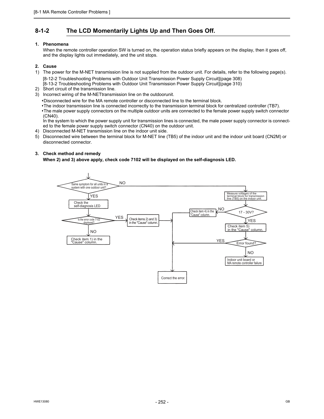
[8-1 MA Remote Controller Problems ]
Hwe13080
Gb
8-1-2 The LCD Momentarily Lights Up and Then Goes Off.(Cn40).
In the system to which the power supply unit for transmission lines is connected, the male power supply connector is connect- ed to the female power supply switch connector (CN40) on the outdoor unit. 4) Disconnected M-NET transmission line on the indoor unit side. 5) Disconnected wire between the terminal block for M-NET line (TB5) of the indoor unit and the indoor unit board (CN2M) or disconnected connector.Yes
Yes
Yes
Yes
No
No
No
No
Same symptom for all units in a system with one outdoor unit? Check the self-diagnosis LED Check item 1) in the "Cause" column. Check items 2) and 3) in the "Cause" column. Check item 4) in the "Cause" column. Measure voltages of the terminal block for transmission line (TB5) on the indoor unit.17 - 30V?
Check item 5) in the "Cause" column. Error found? Indoor unit board or MA remote controller failure Correct the error. Is the error code 7102 displayed?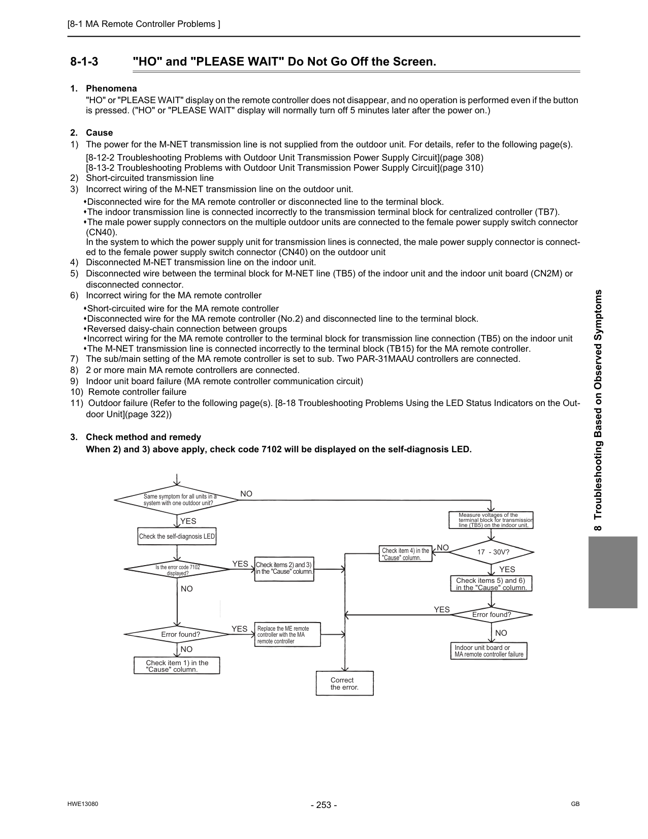
[8-1 MA Remote Controller Problems ]
Hwe13080
Gb
8 Troubleshooting Based on Observed Symptoms 8-1-3 "HO" and "PLEASE WAIT" Do Not Go Off the Screen.(Cn40).
In the system to which the power supply unit for transmission lines is connected, the male power supply connector is connect- ed to the female power supply switch connector (CN40) on the outdoor unit 4) Disconnected M-NET transmission line on the indoor unit. 5) Disconnected wire between the terminal block for M-NET line (TB5) of the indoor unit and the indoor unit board (CN2M) or disconnected connector. 6) Incorrect wiring for the MA remote controller Short-circuited wire for the MA remote controller Disconnected wire for the MA remote controller (No.2) and disconnected line to the terminal block. Reversed daisy-chain connection between groups Incorrect wiring for the MA remote controller to the terminal block for transmission line connection (TB5) on the indoor unit The M-NET transmission line is connected incorrectly to the terminal block (TB15) for the MA remote controller. 7) The sub/main setting of the MA remote controller is set to sub. Two PAR-31MAAU controllers are connected. 8) 2 or more main MA remote controllers are connected. 9) Indoor unit board failure (MA remote controller communication circuit) 10) Remote controller failure 11) Outdoor failure (Refer to the following page(s). [8-18 Troubleshooting Problems Using the LED Status Indicators on the Out- door Unit](page 322))Yes
Yes
Yes
No
No
Yes
Yes
No
No
No
Check the self-diagnosis LED Error found? Error found? Replace the ME remote controller with the MA remote controller17 - 30V?
Same symptom for all units in a system with one outdoor unit? Correct the error. Measure voltages of the terminal block for transmission line (TB5) on the indoor unit. Is the error code 7102 displayed? Indoor unit board or MA remote controller failure Check item 1) in the "Cause" column. Check items 2) and 3) in the "Cause" column. Check item 4) in the "Cause" column. Check items 5) and 6) in the "Cause" column.
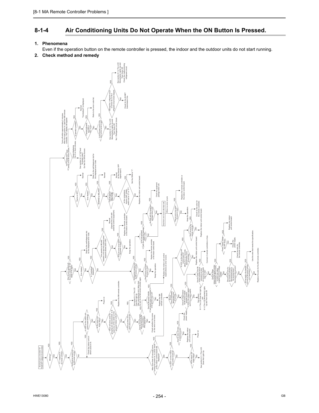
[8-1 MA Remote Controller Problems ]
Hwe13080
Gb
8-1-4 Air Conditioning Units Do Not Operate When the ON Button Is Pressed.Yes
Blinking? Is " " displayed on the remote controller?No
No
No
Yes
Yes
When all wires used for grouping are disconnected, is at least one of the LED2 on the grouped indoor units lit?Yes
Replace the MA remote controller. Is there an indoor unit on which LED2 is turned off? If operated afterwards, error 6602 or 6607 occurs. Check the voltage between the MA remote controller terminals (A and B). 9-13VDC if the voltage is applied and 0V if no voltage is applied. Is LED1 on the indoor unit control board lit? (Blinks for 2 or 3 seconds approximately every 20 seconds) Does the number of the MA remote controllers that are connected to an indoor unit exceed the allowable range (2 units)? Blinking? (Turns on momentarily approximately every 20 seconds) *After correcting the error, daisy-chain the wire for the MA remote controller again. Check for the M-NET transmission line. Replace the indoor unit control board. Connect 2 remote controllers or less. Check whether the screw on the wire is not loose. Is LED2 on the indoor unit control board blinking? When the unit is operated with the remote controller, will "ON" appear on the display? Is "Centralized" displayed? "HO"/"PLEASE WAIT" keeps blinking on the MA remote controller. Is only the power source of the indoor unit turn turned on again? DEMAND by MELANS? External thermo input setting?(Sw3-3=On)
Does an error occur when the power is reset? Does the unit work properly when the wire for the MA remote controller is daisy-chained again? Is LED1 on the indoor unit control board lit? Does the MA remote controller work properly when it is connected to the specified indoor unit? Does an error occur when the power is reset? Running group operation with the MA remote controller? Is the unit grouped with the equipment package indoor unit? No fault with the equipment package indoor unit? Does an error occur when the power is reset? Check that no error occurs in other indoor units. Check the indoor unit on which LED2 is lit. All the indoor unit power failure? All the indoor unit power failure? Error display? Error display? Thermo is OFF? Is operation possible? Short circuit of the remote controller? After turning the power on, check whether "HO"/ "PLEASE WAIT" is displayed on the remote controller. After more than 20 seconds since turning the power on, is LED2 check of the indoor control board still displayed? Is the operation by MELANS forbidden or the input from external control equipment allowed (SWC=ON)? Is the compulsory thermo OFF (SWA) switch set to "2" or "3"? Although No.1 refrigerant circuit is normal, No.2 or No.3 refrigerant circuit remain stopped. Running group operation with the MA remote controller? Does the indoor unit make an instantaneous stop? Power supply voltageAc188~253V?
No
Yes
No
No
No
No
No
No
No
No
When no error occursNo
No
No
Keep displaying for 5 or more minutes.No
No
No
No
No
No
No
No
No
No
No
No
Check the power supply. Check the wire for the remote controller.No
Replace the indoor unit control board.No
No
No
No
No
Replace the MA remote controller.No
Replace the remote controller or the indoor control board.Yes
Replace the indoor unit control board where an error occurs. Keep the operation.No
No
No
No
Keep the operation.Yes
Yes
Yes
Yes
Power onYes
Refer to the self-diagnosis list for the displayed error code.Yes
Normal Turns off within approximately 5 minutes. After the main power on, start the MA remote controller. "HO" display will appear.Yes
Normal "Centralized" is displayed.Yes
Refer to the error code list.Yes
Yes
Yes
NormalYes
Normal (Is the thermo OFF signal input?)Yes
Set the SWA to "1".Yes
Refer to the self-diagnosis list for the displayed error code.Yes
Yes
Yes
Yes
Check the equipment package indoor unit.Yes
Replace the remote controller or the indoor control board. Replace the indoor unit control board.Yes
Yes
Yes
Replace the remote controller or the indoor control board. Normal (Operate the unit with external control equipment)Yes
Yes
Replace the indoor unit control board. Check the power supply.Yes
Yes
Yes
Yes
Check the voltage between the MA remote controller terminal blocks (TB15) (A and B). 9-13VDC if the voltage is applied and 0V if no voltage is applied.No
Disconnected wire for the remote controller? Disconnected wire to the terminal block? Disconnected relay connector?No
Are the length or the diameter of the wire for MA remote controller out of specification?No
Yes
Yes
Use the wire that meets the specification. Replace the wire for the MA remote controller.Yes
Check for the wire for the remote controller. Keep the operation.Yes
Replace the indoor unit control board.Yes
Yes
Yes
Power on See section 8-1-1 The LCD Does Not Light Up. See section 8-1-1 The LCD Does Not Light Up. See sections 8-1-1 The LCD Does Not Light Up and 8-1-2 The LCD Momentarily Lights Up and Then Goes Off. See section 8-1-3 "HO"and"Please Wait"
Do Not Go Off the Screen. See section 8-1-2 The LCD Momentarily Lights Up and Then Goes Off. No.1 Refrigerant circuit check See section 8-1-2 The LCD Momentarily Lights Up and Then Goes Off. Check the malfunctioning refrigerant circuit.
[8-2 ME remote Controller Problems ]
Hwe13080
Gb
8 Troubleshooting Based on Observed Symptoms 8-2 ME remote Controller Problems 8-2-1 The LCD Does Not Light Up.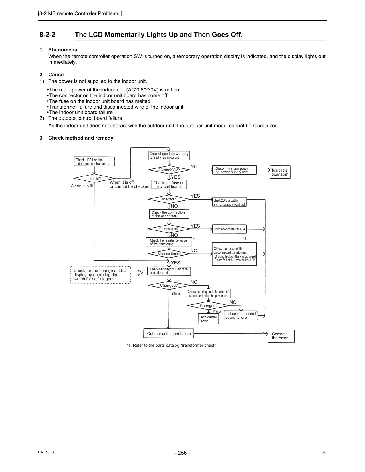
[8-2 ME remote Controller Problems ]
Hwe13080
Gb
8-2-2 The LCD Momentarily Lights Up and Then Goes Off.Yes
Yes
Yes
Yes
Yes
No
No
No
No
No
No
Yes
*1 *1 Check LED1 on the indoor unit control board. Is it lit? When it is lit When it is off or cannot be checked Check for the change of LED display by operating dip switch for self-diagnosis. Check voltage of the power supply terminal on the indoor unit.Ac208/230V?
Check the fuse on the circuit board. Melted? Check 200V circuit for short circuit and ground fault Check the connection of the connector. Check the main power of the power supply wire Turn on the power again. Connector contact failure Disconnected? Check the resistance value of the transformer Within specification? Check the cause of the disconnected transformer. Ground fault on the circuit board Ground fault of the sensor and the LEV Check self-diagnosis function of outdoor unit Changed? Changed? Outdoor unit board failure Check self-diagnosis function of outdoor unit after the power on. Accidental error Indoor unit control board failure Correct the error. *1. Refer to the parts catalog “transformer check”.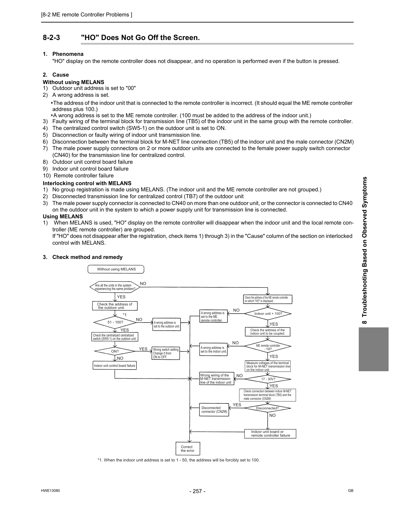
[8-2 ME remote Controller Problems ]
Hwe13080
Gb
8 Troubleshooting Based on Observed Symptoms 8-2-3 "HO" Does Not Go Off the Screen.Yes
Yes
Yes
Yes
Yes
Yes
Yes
No
No
*1 *1. When the indoor unit address is set to 1 - 50, the address will be forcibly set to 100.No
No
No
No
No
Without using MELANS Are all the units in the system experiencing the same problem? Check the address of the outdoor unit. 51 - 100? Check the centralized centralized switch (SW5-1) on the outdoor unit.On?
Indoor unit control board failure A wrong address is set to the outdoor unit. Wrong switch setting Change it from ON to OFF. A wrong address is set to the ME remote controller. A wrong address is set to the indoor unit. Wrong wiring of the M-NET transmission line of the indoor unit Disconnected connector (CN2M) Correct the error. Disconnected?17 - 30V?
ME remote controller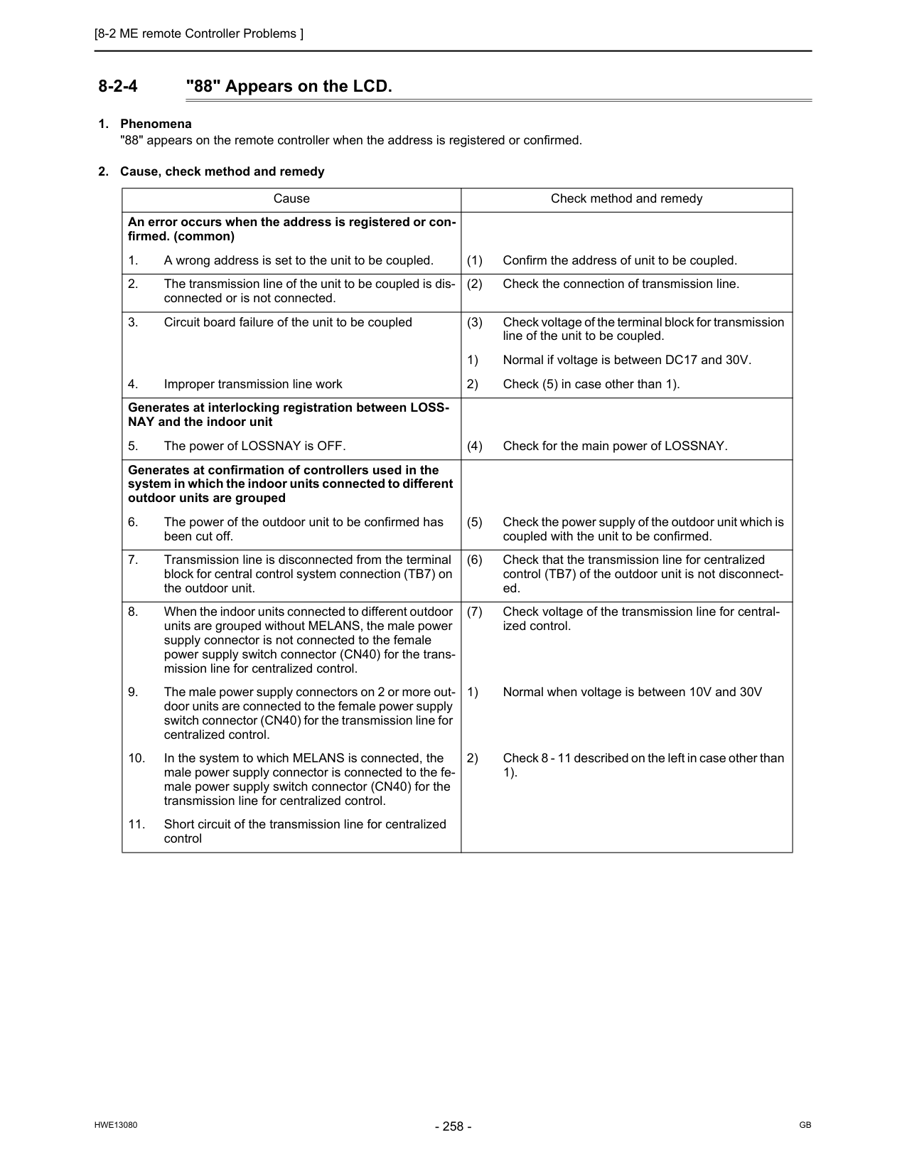
[8-2 ME remote Controller Problems ]
Hwe13080
Gb
8-2-4 "88" Appears on the LCD.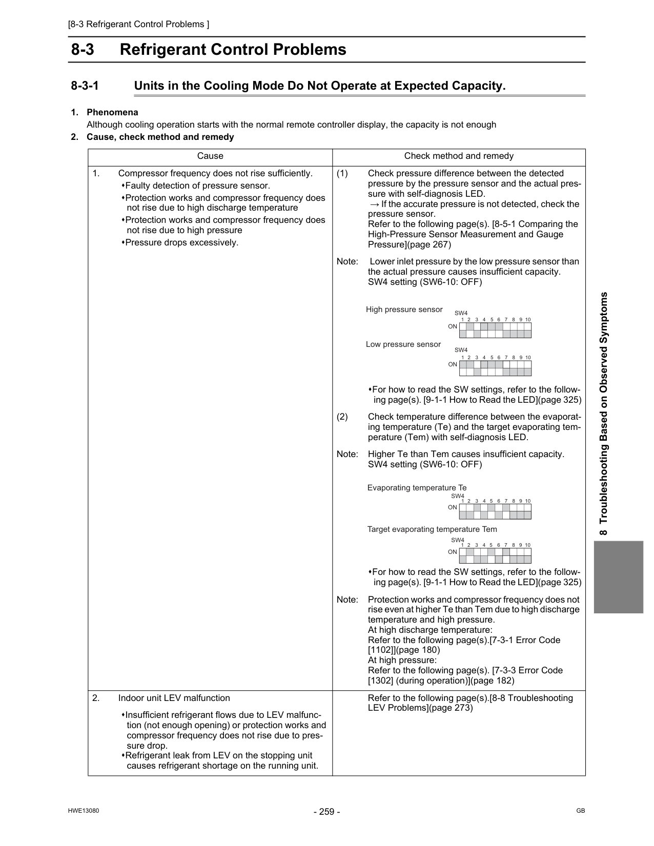
[8-3 Refrigerant Control Problems ]
Hwe13080
Gb
8 Troubleshooting Based on Observed Symptoms 8-3 Refrigerant Control Problems 8-3-1 Units in the Cooling Mode Do Not Operate at Expected Capacity.On
1 2 3 4 5 6 7 8 9 10On
1 2 3 4 5 6 7 8 9 10Sw4
Sw4
1 2 3 4 5 6 7 8 9 10 Evaporating temperature Te Target evaporating temperature TemOn
1 2 3 4 5 6 7 8 9 10On
Sw4
Sw4

[8-3 Refrigerant Control Problems ]
Hwe13080
Gb
Cause Check method and remedy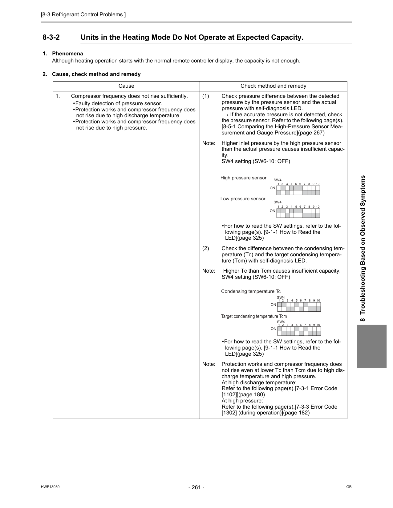
[8-3 Refrigerant Control Problems ]
Hwe13080
Gb
8 Troubleshooting Based on Observed Symptoms 8-3-2 Units in the Heating Mode Do Not Operate at Expected Capacity.On
1 2 3 4 5 6 7 8 9 10On
1 2 3 4 5 6 7 8 9 10Sw4
Sw4
Condensing temperature Tc Target condensing temperature TcmOn
On
1 2 3 4 5 6 7 8 9 10 1 2 3 4 5 6 7 8 9 10Sw4
Sw4
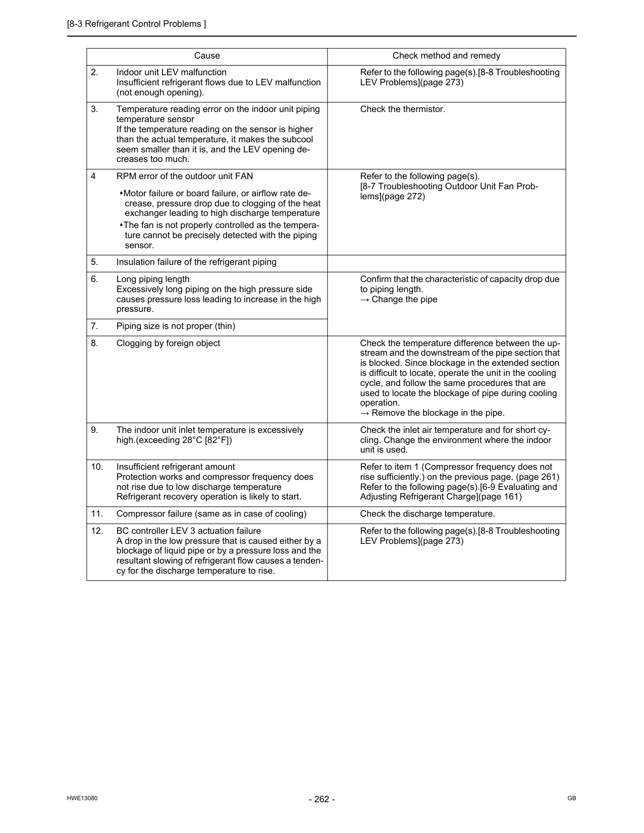
[8-3 Refrigerant Control Problems ]
Hwe13080
Gb
Cause Check method and remedy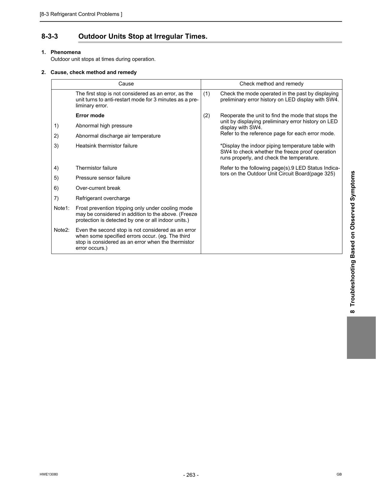
[8-3 Refrigerant Control Problems ]
Hwe13080
Gb
8 Troubleshooting Based on Observed Symptoms 8-3-3 Outdoor Units Stop at Irregular Times.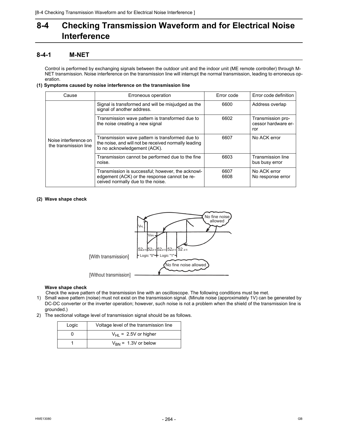
[8-4 Checking Transmission Waveform and for Electrical Noise Interference ]
Hwe13080
Gb
8-4 Checking Transmission Waveform and for Electrical Noise Interference 8-4-1M-Net
Control is performed by exchanging signals between the outdoor unit and the indoor unit (ME remote controller) through M- NET transmission. Noise interference on the transmission line will interrupt the normal transmission, leading to erroneous op- eration. (1) Symptoms caused by noise interference on the transmission line (2) Wave shape check Wave shape check Check the wave pattern of the transmission line with an oscilloscope. The following conditions must be met. 1) Small wave pattern (noise) must not exist on the transmission signal. (Minute noise (approximately 1V) can be generated by DC-DC converter or the inverter operation; however, such noise is not a problem when the shield of the transmission line is grounded.) 2) The sectional voltage level of transmission signal should be as follows. Cause Erroneous operation Error code Error code definition Noise interference on the transmission line Signal is transformed and will be misjudged as the signal of another address. 6600 Address overlap Transmission wave pattern is transformed due to the noise creating a new signal 6602 Transmission pro- cessor hardware er- ror Transmission wave pattern is transformed due to the noise, and will not be received normally leading to no acknowledgement (ACK). 6607 No ACK error Transmission cannot be performed due to the fine noise. 6603 Transmission line bus busy error Transmission is successful; however, the acknowl- edgement (ACK) or the response cannot be re- ceived normally due to the noise. 6607 6608 No ACK error No response error Logic Voltage level of the transmission line 0 VHL = 2.5V or higher 1 VBN = 1.3V or below [With transmission] [Without transmission] No fine noise allowed No fine noise allowed 52 52 52 52 52Vbn
Vhl
Logic "0" Logic "1"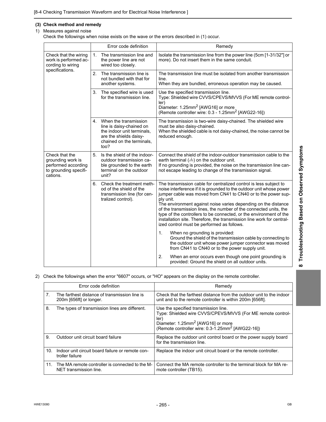
[8-4 Checking Transmission Waveform and for Electrical Noise Interference ]
Hwe13080
Gb
8 Troubleshooting Based on Observed Symptoms (3) Check method and remedy 1) Measures against noise Check the followings when noise exists on the wave or the errors described in (1) occur. 2) Check the followings when the error "6607" occurs, or "HO" appears on the display on the remote controller. Error code definition Remedy Check that the wiring work is performed ac- cording to wiring specifications.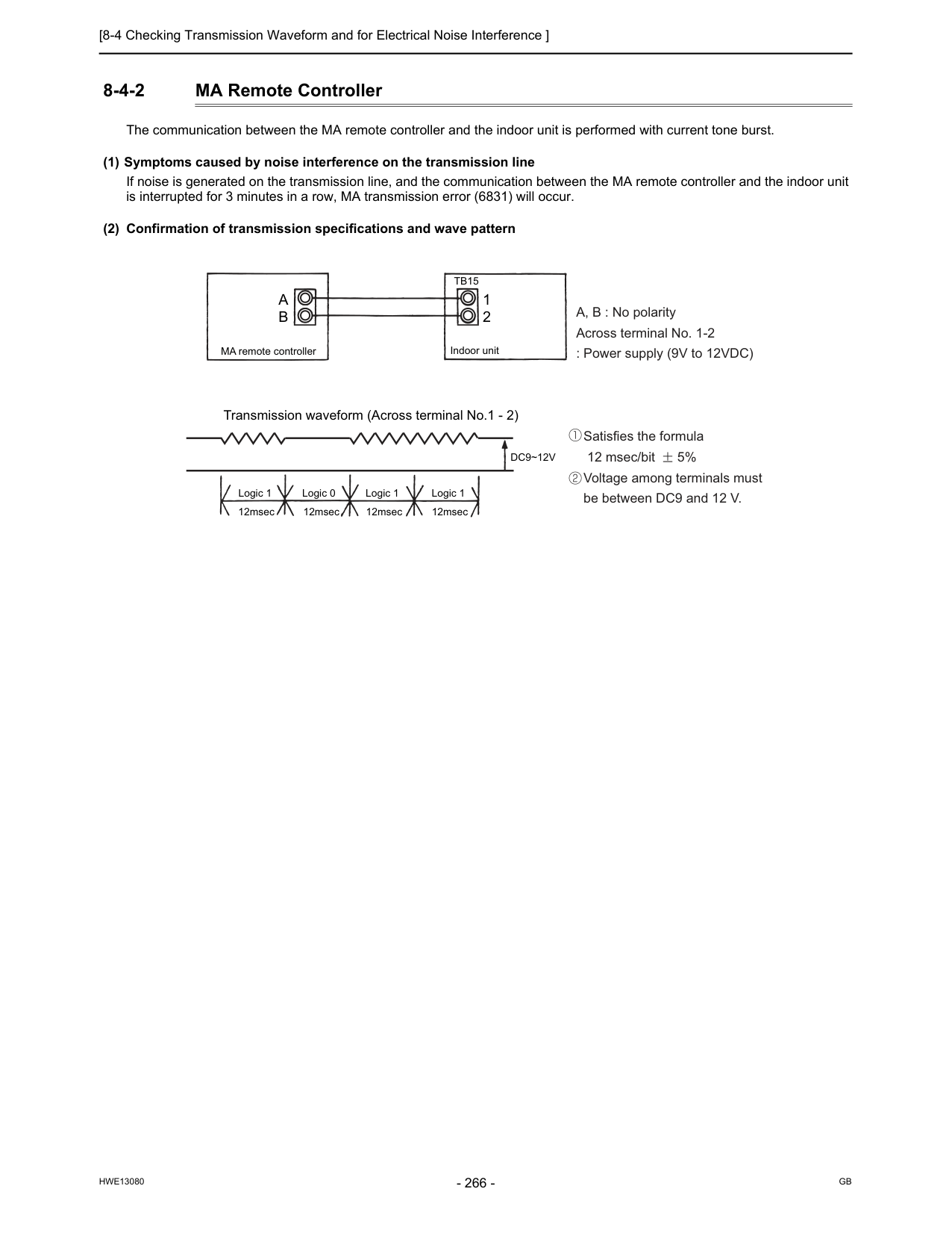
[8-4 Checking Transmission Waveform and for Electrical Noise Interference ]
Hwe13080
Gb
8-4-2 MA Remote Controller The communication between the MA remote controller and the indoor unit is performed with current tone burst. (1) Symptoms caused by noise interference on the transmission line If noise is generated on the transmission line, and the communication between the MA remote controller and the indoor unit is interrupted for 3 minutes in a row, MA transmission error (6831) will occur. (2) Confirmation of transmission specifications and wave pattern A, B : No polarity Across terminal No. 1-2 : Power supply (9V to 12VDC) Satisfies the formula 12 msec/bit 5% Voltage among terminals must be between DC9 and 12 V.Tb15
A
B
1 2 MA remote controller Transmission waveform (Across terminal No.1 - 2)Dc9~12V
Logic 1 Logic 0 Logic 1 Logic 1 12msec 12msec 12msec 12msec Indoor unit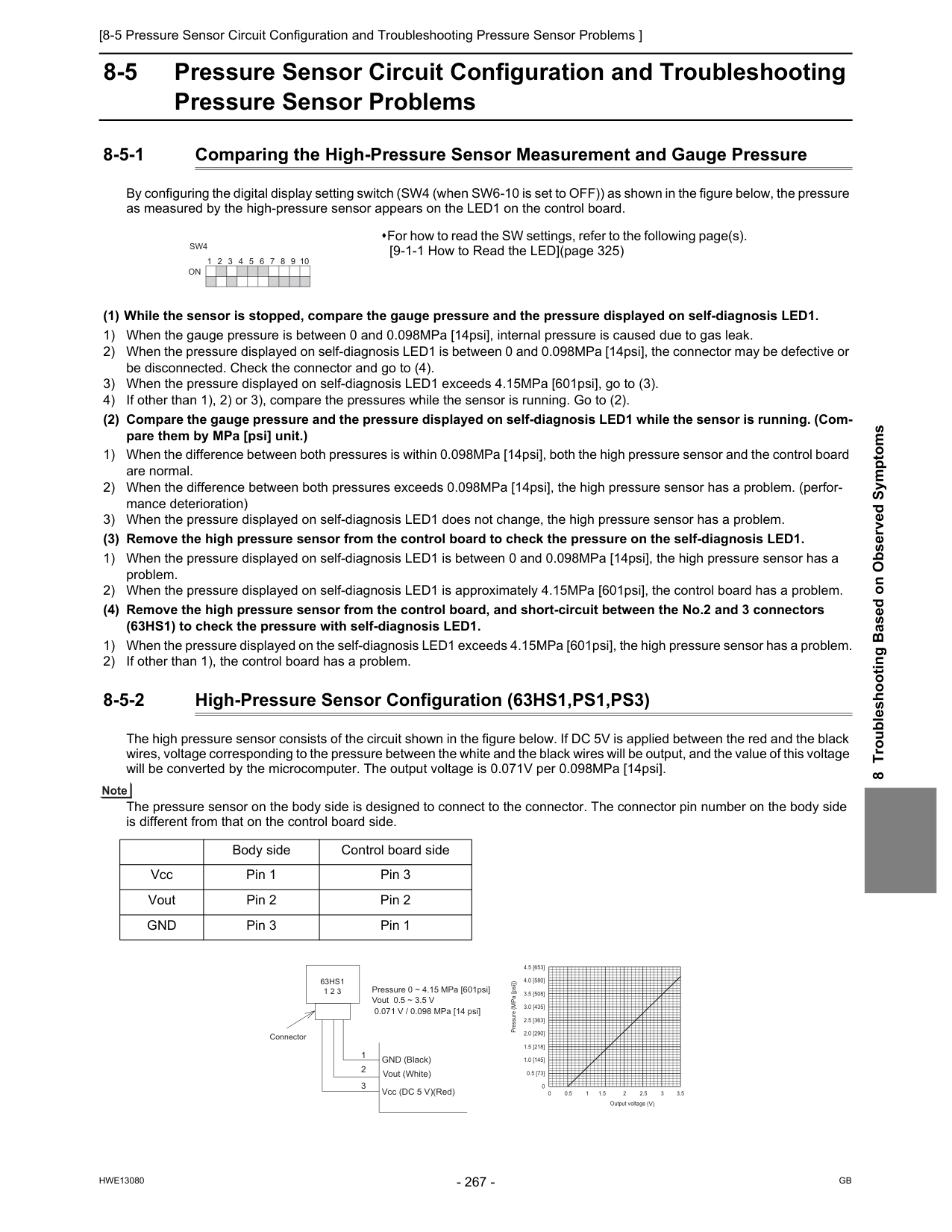
[8-5 Pressure Sensor Circuit Configuration and Troubleshooting Pressure Sensor Problems ]
Hwe13080
Gb
8 Troubleshooting Based on Observed Symptoms 8-5 Pressure Sensor Circuit Configuration and Troubleshooting Pressure Sensor Problems 8-5-1 Comparing the High-Pressure Sensor Measurement and Gauge Pressure By configuring the digital display setting switch (SW4 (when SW6-10 is set to OFF)) as shown in the figure below, the pressure as measured by the high-pressure sensor appears on the LED1 on the control board. (1) While the sensor is stopped, compare the gauge pressure and the pressure displayed on self-diagnosis LED1. 1) When the gauge pressure is between 0 and 0.098MPa [14psi], internal pressure is caused due to gas leak. 2) When the pressure displayed on self-diagnosis LED1 is between 0 and 0.098MPa [14psi], the connector may be defective or be disconnected. Check the connector and go to (4). 3) When the pressure displayed on self-diagnosis LED1 exceeds 4.15MPa [601psi], go to (3). 4) If other than 1), 2) or 3), compare the pressures while the sensor is running. Go to (2). (2) Compare the gauge pressure and the pressure displayed on self-diagnosis LED1 while the sensor is running. (Com- pare them by MPa [psi] unit.) 1) When the difference between both pressures is within 0.098MPa [14psi], both the high pressure sensor and the control board are normal. 2) When the difference between both pressures exceeds 0.098MPa [14psi], the high pressure sensor has a problem. (perfor- mance deterioration) 3) When the pressure displayed on self-diagnosis LED1 does not change, the high pressure sensor has a problem. (3) Remove the high pressure sensor from the control board to check the pressure on the self-diagnosis LED1. 1) When the pressure displayed on self-diagnosis LED1 is between 0 and 0.098MPa [14psi], the high pressure sensor has a problem. 2) When the pressure displayed on self-diagnosis LED1 is approximately 4.15MPa [601psi], the control board has a problem. (4) Remove the high pressure sensor from the control board, and short-circuit between the No.2 and 3 connectors (63HS1) to check the pressure with self-diagnosis LED1. 1) When the pressure displayed on the self-diagnosis LED1 exceeds 4.15MPa [601psi], the high pressure sensor has a problem. 2) If other than 1), the control board has a problem. 8-5-2 High-Pressure Sensor Configuration (63HS1,PS1,PS3) The high pressure sensor consists of the circuit shown in the figure below. If DC 5V is applied between the red and the black wires, voltage corresponding to the pressure between the white and the black wires will be output, and the value of this voltage will be converted by the microcomputer. The output voltage is 0.071V per 0.098MPa [14psi]. The pressure sensor on the body side is designed to connect to the connector. The connector pin number on the body side is different from that on the control board side. For how to read the SW settings, refer to the following page(s). [9-1-1 How to Read the LED](page 325) 1 2 3 4 5 6 7 8 9 10On
Sw4
Body side Control board side Vcc Pin 1 Pin 3 Vout Pin 2 Pin 2Gnd
Pin 3 Pin 1 0 0.5 [73] 1.0 [145] 1.5 [218] 2.0 [290] 2.5 [363] 3.0 [435] 3.5 [508] 4.0 [580] 4.5 [653] 0 0.5 1 1.5 2 2.5 3 3.5Output voltage (V)
Pressure (MPa [psi]) Connector
63Hs1
1 2 3 1 2 3 GND (Black) Vout (White) Vcc (DC 5 V)(Red) Pressure 0 ~ 4.15 MPa [601psi] Vout 0.5 ~ 3.5 V 0.071 V / 0.098 MPa [14 psi]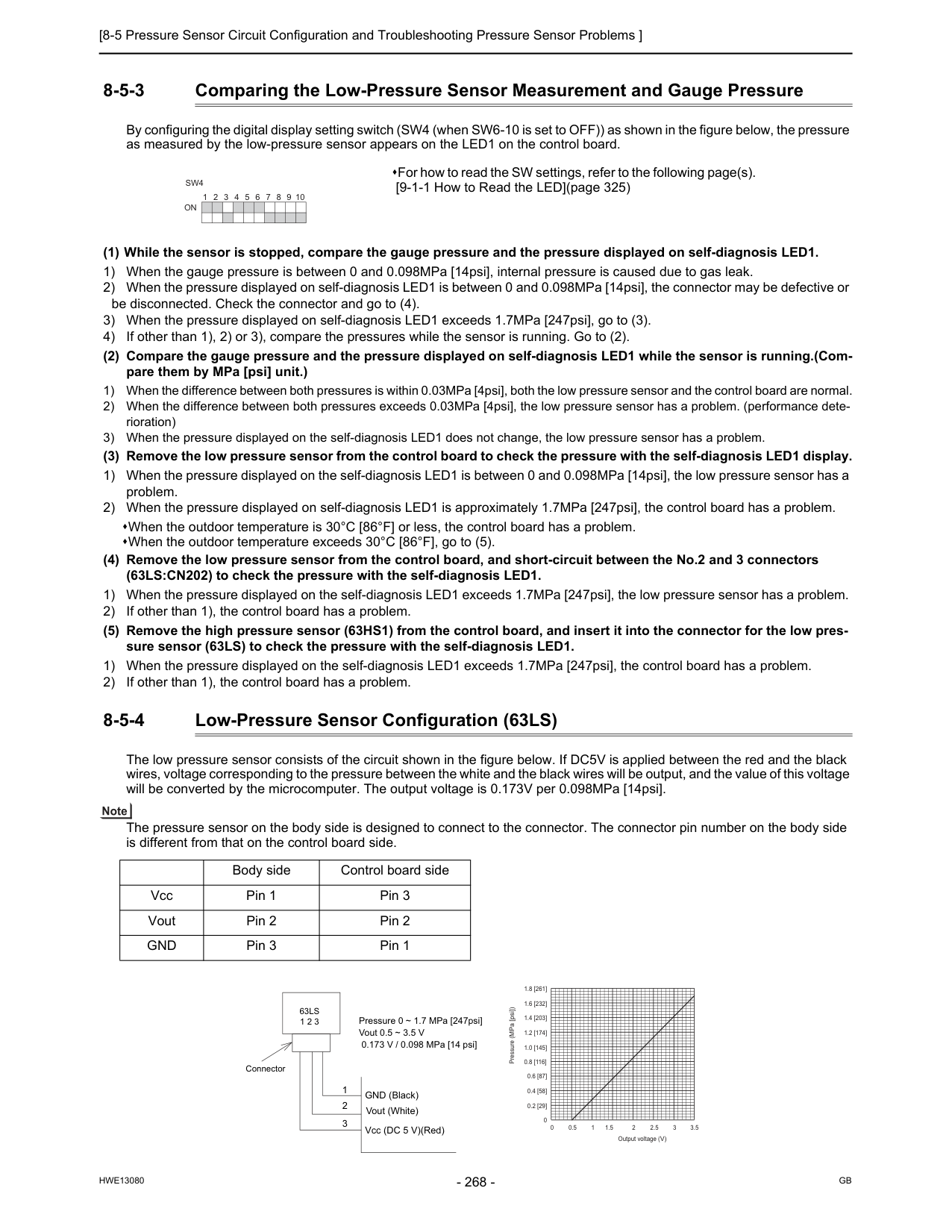
[8-5 Pressure Sensor Circuit Configuration and Troubleshooting Pressure Sensor Problems ]
Hwe13080
Gb
8-5-3 Comparing the Low-Pressure Sensor Measurement and Gauge Pressure By configuring the digital display setting switch (SW4 (when SW6-10 is set to OFF)) as shown in the figure below, the pressure as measured by the low-pressure sensor appears on the LED1 on the control board. (1) While the sensor is stopped, compare the gauge pressure and the pressure displayed on self-diagnosis LED1. 1) When the gauge pressure is between 0 and 0.098MPa [14psi], internal pressure is caused due to gas leak. 2) When the pressure displayed on self-diagnosis LED1 is between 0 and 0.098MPa [14psi], the connector may be defective or be disconnected. Check the connector and go to (4). 3) When the pressure displayed on self-diagnosis LED1 exceeds 1.7MPa [247psi], go to (3). 4) If other than 1), 2) or 3), compare the pressures while the sensor is running. Go to (2). (2) Compare the gauge pressure and the pressure displayed on self-diagnosis LED1 while the sensor is running.(Com- pare them by MPa [psi] unit.) 1) When the difference between both pressures is within 0.03MPa [4psi], both the low pressure sensor and the control board are normal. 2) When the difference between both pressures exceeds 0.03MPa [4psi], the low pressure sensor has a problem. (performance dete- rioration) 3) When the pressure displayed on the self-diagnosis LED1 does not change, the low pressure sensor has a problem. (3) Remove the low pressure sensor from the control board to check the pressure with the self-diagnosis LED1 display. 1) When the pressure displayed on the self-diagnosis LED1 is between 0 and 0.098MPa [14psi], the low pressure sensor has a problem. 2) When the pressure displayed on self-diagnosis LED1 is approximately 1.7MPa [247psi], the control board has a problem. When the outdoor temperature is 30°C [86°F] or less, the control board has a problem. When the outdoor temperature exceeds 30°C [86°F], go to (5). (4) Remove the low pressure sensor from the control board, and short-circuit between the No.2 and 3 connectors (63LS:CN202) to check the pressure with the self-diagnosis LED1. 1) When the pressure displayed on the self-diagnosis LED1 exceeds 1.7MPa [247psi], the low pressure sensor has a problem. 2) If other than 1), the control board has a problem. (5) Remove the high pressure sensor (63HS1) from the control board, and insert it into the connector for the low pres- sure sensor (63LS) to check the pressure with the self-diagnosis LED1. 1) When the pressure displayed on the self-diagnosis LED1 exceeds 1.7MPa [247psi], the control board has a problem. 2) If other than 1), the control board has a problem. 8-5-4 Low-Pressure Sensor Configuration (63LS) The low pressure sensor consists of the circuit shown in the figure below. If DC5V is applied between the red and the black wires, voltage corresponding to the pressure between the white and the black wires will be output, and the value of this voltage will be converted by the microcomputer. The output voltage is 0.173V per 0.098MPa [14psi]. The pressure sensor on the body side is designed to connect to the connector. The connector pin number on the body side is different from that on the control board side. For how to read the SW settings, refer to the following page(s). [9-1-1 How to Read the LED](page 325) 1 2 3 4 5 6 7 8 9 10On
Sw4
Body side Control board side Vcc Pin 1 Pin 3 Vout Pin 2 Pin 2Gnd
Pin 3 Pin 1 0 0.2 [29] 0.4 [58] 0.6 [87] 0.8 [116] 1.0 [145] 1.2 [174] 1.4 [203] 1.6 [232] 1.8 [261] 0 0.5 1 1.5 2 2.5 3 3.5Output voltage (V)
Pressure (MPa [psi]) Connector
63Ls
1 2 3 1 2 3 GND (Black) Vout (White) Vcc (DC 5 V)(Red) Pressure 0 ~ 1.7 MPa [247psi] Vout 0.5 ~ 3.5 V 0.173 V / 0.098 MPa [14 psi]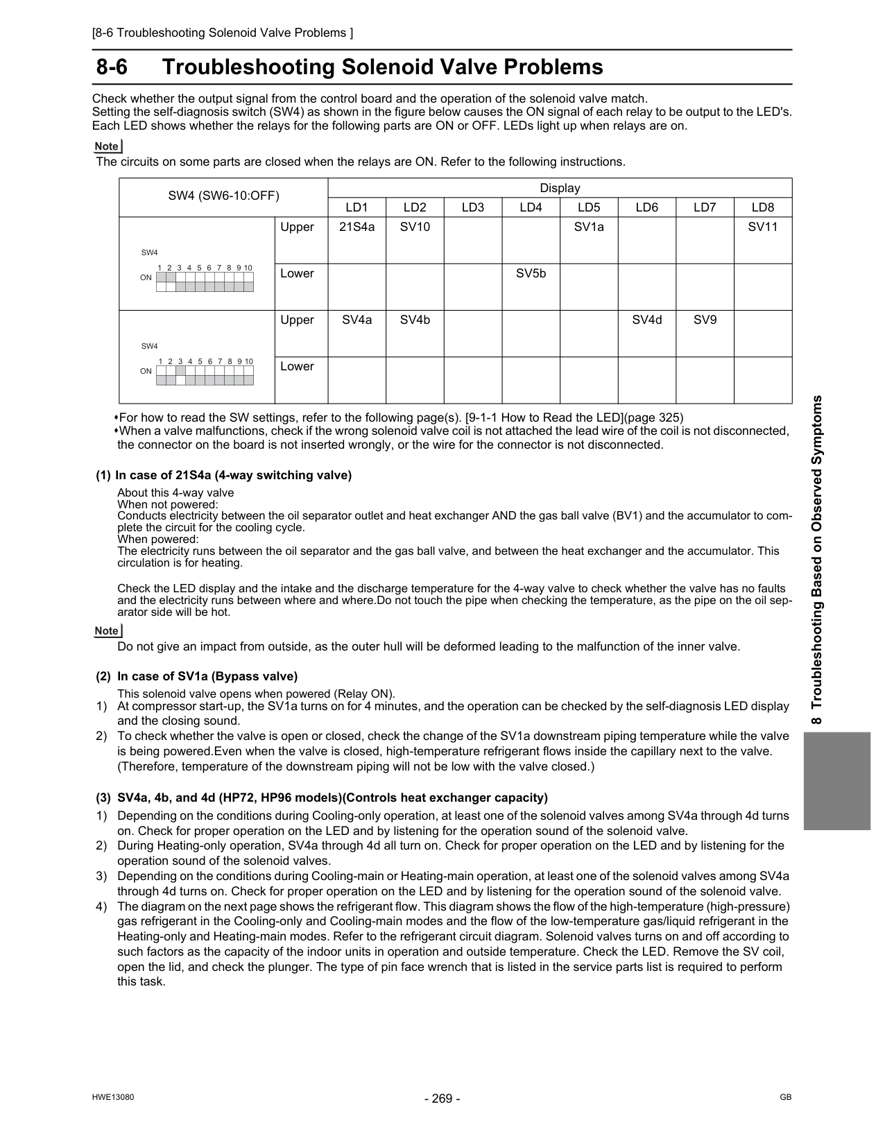
[8-6 Troubleshooting Solenoid Valve Problems ]
Hwe13080
Gb
8 Troubleshooting Based on Observed Symptoms 8-6 Troubleshooting Solenoid Valve Problems Check whether the output signal from the control board and the operation of the solenoid valve match. Setting the self-diagnosis switch (SW4) as shown in the figure below causes the ON signal of each relay to be output to the LED's. Each LED shows whether the relays for the following parts are ON or OFF. LEDs light up when relays are on. The circuits on some parts are closed when the relays are ON. Refer to the following instructions. For how to read the SW settings, refer to the following page(s). [9-1-1 How to Read the LED](page 325) When a valve malfunctions, check if the wrong solenoid valve coil is not attached the lead wire of the coil is not disconnected, the connector on the board is not inserted wrongly, or the wire for the connector is not disconnected. (1) In case of 21S4a (4-way switching valve) About this 4-way valve When not powered: Conducts electricity between the oil separator outlet and heat exchanger AND the gas ball valve (BV1) and the accumulator to com- plete the circuit for the cooling cycle. When powered: The electricity runs between the oil separator and the gas ball valve, and between the heat exchanger and the accumulator. This circulation is for heating. Check the LED display and the intake and the discharge temperature for the 4-way valve to check whether the valve has no faults and the electricity runs between where and where.Do not touch the pipe when checking the temperature, as the pipe on the oil sep- arator side will be hot. Do not give an impact from outside, as the outer hull will be deformed leading to the malfunction of the inner valve. (2) In case of SV1a (Bypass valve) This solenoid valve opens when powered (Relay ON). 1) At compressor start-up, the SV1a turns on for 4 minutes, and the operation can be checked by the self-diagnosis LED display and the closing sound. 2) To check whether the valve is open or closed, check the change of the SV1a downstream piping temperature while the valve is being powered.Even when the valve is closed, high-temperature refrigerant flows inside the capillary next to the valve. (Therefore, temperature of the downstream piping will not be low with the valve closed.) (3) SV4a, 4b, and 4d (HP72, HP96 models)(Controls heat exchanger capacity) 1) Depending on the conditions during Cooling-only operation, at least one of the solenoid valves among SV4a through 4d turns on. Check for proper operation on the LED and by listening for the operation sound of the solenoid valve. 2) During Heating-only operation, SV4a through 4d all turn on. Check for proper operation on the LED and by listening for the operation sound of the solenoid valves. 3) Depending on the conditions during Cooling-main or Heating-main operation, at least one of the solenoid valves among SV4a through 4d turns on. Check for proper operation on the LED and by listening for the operation sound of the solenoid valve. 4) The diagram on the next page shows the refrigerant flow. This diagram shows the flow of the high-temperature (high-pressure) gas refrigerant in the Cooling-only and Cooling-main modes and the flow of the low-temperature gas/liquid refrigerant in the Heating-only and Heating-main modes. Refer to the refrigerant circuit diagram. Solenoid valves turns on and off according to such factors as the capacity of the indoor units in operation and outside temperature. Check the LED. Remove the SV coil, open the lid, and check the plunger. The type of pin face wrench that is listed in the service parts list is required to perform this task.Sw4 (Sw6-10:Off)
DisplayLd1
Ld2
Ld3
Ld4
Ld5
Ld6
Ld7
Ld8
Upper 21S4aSv10
SV1aSv11
Lower SV5b Upper SV4a SV4b SV4dSv9
Lower 1 2 3 4 5 6 7 8 9 10On
Sw4
On
Sw4
1 2 3 4 5 6 7 8 9 10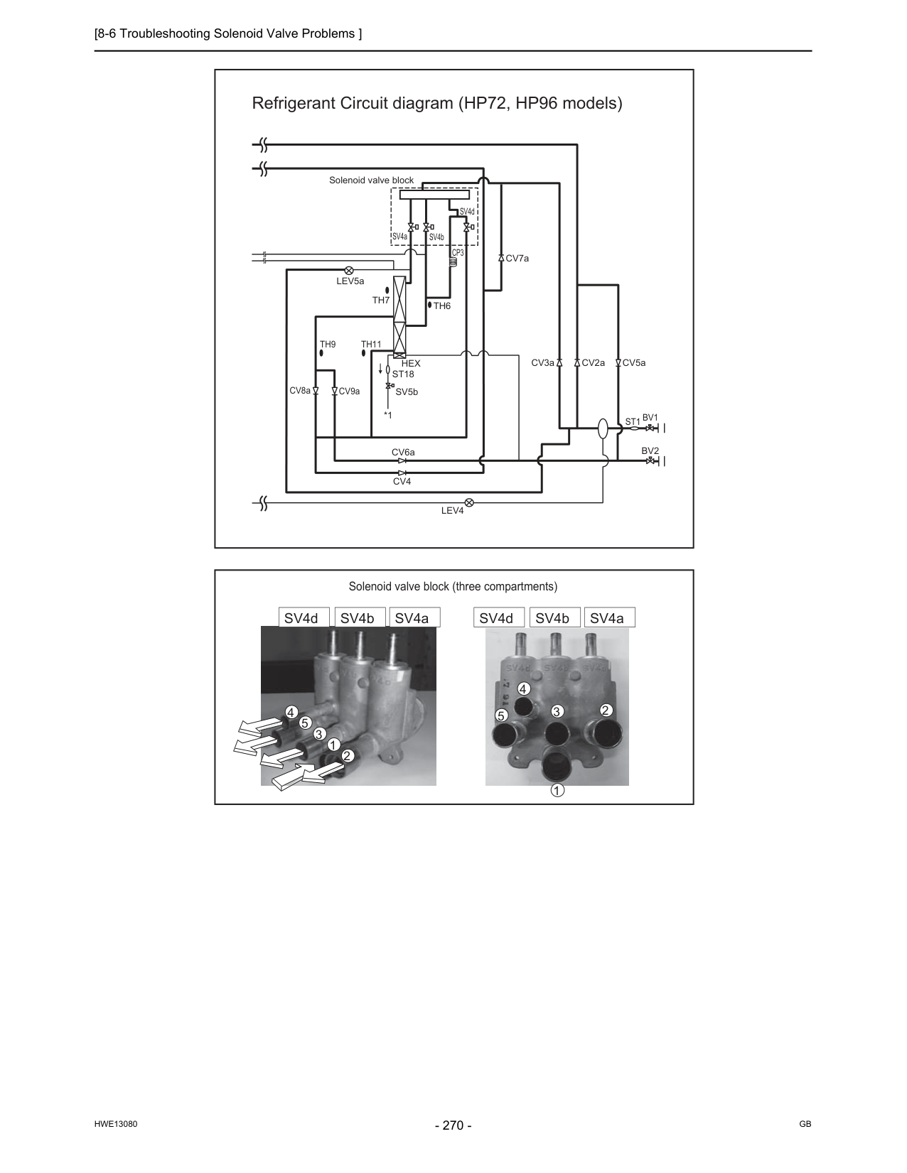
[8-6 Troubleshooting Solenoid Valve Problems ]
Hwe13080
Gb
Refrigerant Circuit diagram (HP72, HP96 models) 1 2 3 4 5 1 2 3 4 5 Solenoid valve block (three compartments) SV4d SV4b SV4a SV4d SV4b SV4a Solenoid valve blockBv2
St1 Bv1
CV8a CV6aTh7
SV4a SV4b SV4dTh6
CV9aTh9
Th11
Cv4
CV2a CV7a CV3a CV5a SV5bHex
St18
LEV5aLev4
*1Cp3
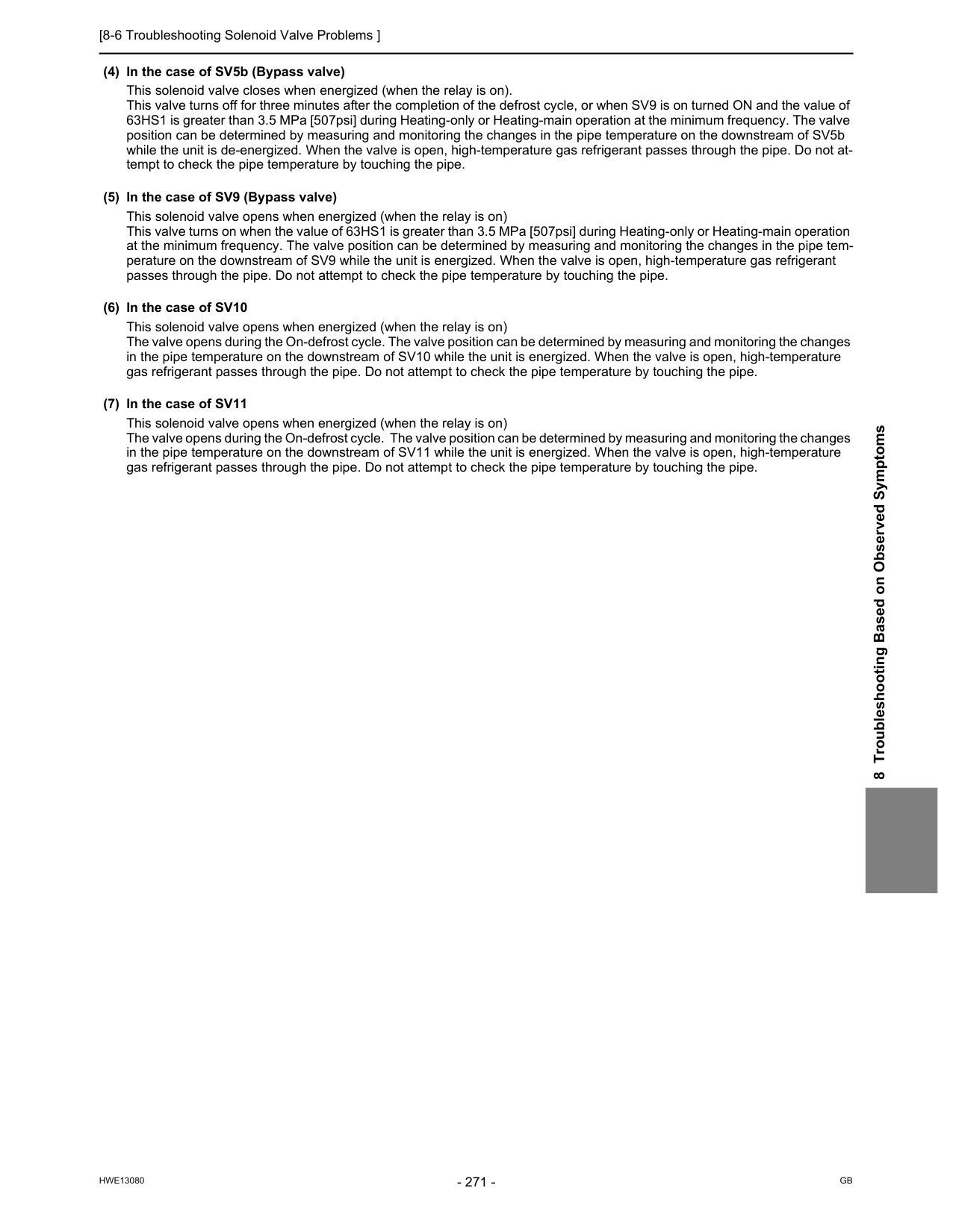
[8-6 Troubleshooting Solenoid Valve Problems ]
Hwe13080
Gb
8 Troubleshooting Based on Observed Symptoms (4) In the case of SV5b (Bypass valve) This solenoid valve closes when energized (when the relay is on). This valve turns off for three minutes after the completion of the defrost cycle, or when SV9 is on turned ON and the value of 63HS1 is greater than 3.5 MPa [507psi] during Heating-only or Heating-main operation at the minimum frequency. The valve position can be determined by measuring and monitoring the changes in the pipe temperature on the downstream of SV5b while the unit is de-energized. When the valve is open, high-temperature gas refrigerant passes through the pipe. Do not at- tempt to check the pipe temperature by touching the pipe. (5) In the case of SV9 (Bypass valve) This solenoid valve opens when energized (when the relay is on) This valve turns on when the value of 63HS1 is greater than 3.5 MPa [507psi] during Heating-only or Heating-main operation at the minimum frequency. The valve position can be determined by measuring and monitoring the changes in the pipe tem- perature on the downstream of SV9 while the unit is energized. When the valve is open, high-temperature gas refrigerant passes through the pipe. Do not attempt to check the pipe temperature by touching the pipe. (6) In the case of SV10 This solenoid valve opens when energized (when the relay is on) The valve opens during the On-defrost cycle. The valve position can be determined by measuring and monitoring the changes in the pipe temperature on the downstream of SV10 while the unit is energized. When the valve is open, high-temperature gas refrigerant passes through the pipe. Do not attempt to check the pipe temperature by touching the pipe. (7) In the case of SV11 This solenoid valve opens when energized (when the relay is on) The valve opens during the On-defrost cycle. The valve position can be determined by measuring and monitoring the changes in the pipe temperature on the downstream of SV11 while the unit is energized. When the valve is open, high-temperature gas refrigerant passes through the pipe. Do not attempt to check the pipe temperature by touching the pipe.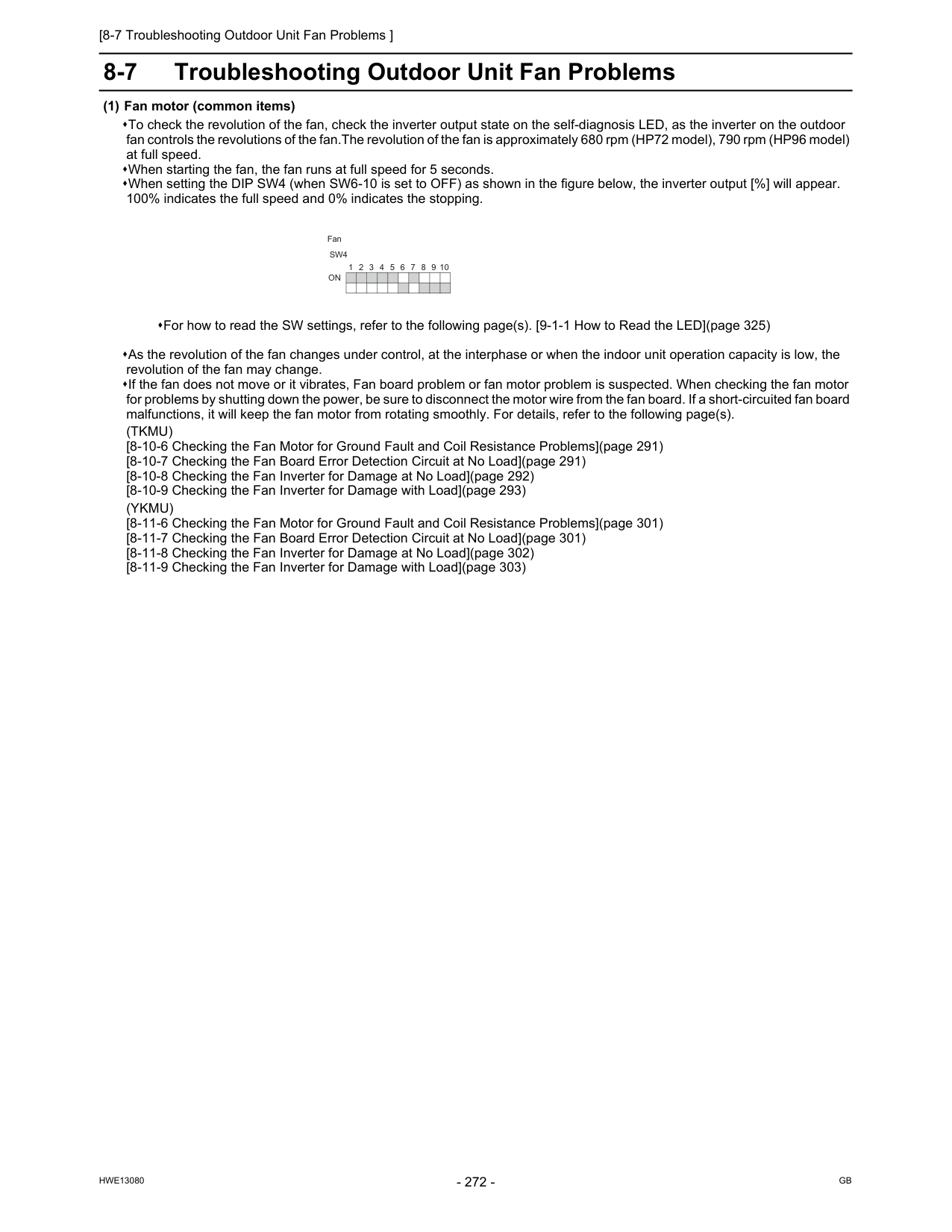
[8-7 Troubleshooting Outdoor Unit Fan Problems ]
Hwe13080
Gb
8-7 Troubleshooting Outdoor Unit Fan Problems (1) Fan motor (common items) To check the revolution of the fan, check the inverter output state on the self-diagnosis LED, as the inverter on the outdoor fan controls the revolutions of the fan.The revolution of the fan is approximately 680 rpm (HP72 model), 790 rpm (HP96 model) at full speed. When starting the fan, the fan runs at full speed for 5 seconds. When setting the DIP SW4 (when SW6-10 is set to OFF) as shown in the figure below, the inverter output [%] will appear. 100% indicates the full speed and 0% indicates the stopping. As the revolution of the fan changes under control, at the interphase or when the indoor unit operation capacity is low, the revolution of the fan may change. If the fan does not move or it vibrates, Fan board problem or fan motor problem is suspected. When checking the fan motor for problems by shutting down the power, be sure to disconnect the motor wire from the fan board. If a short-circuited fan board malfunctions, it will keep the fan motor from rotating smoothly. For details, refer to the following page(s).(Tkmu)
[8-10-6 Checking the Fan Motor for Ground Fault and Coil Resistance Problems](page 291) [8-10-7 Checking the Fan Board Error Detection Circuit at No Load](page 291) [8-10-8 Checking the Fan Inverter for Damage at No Load](page 292) [8-10-9 Checking the Fan Inverter for Damage with Load](page 293)(Ykmu)
[8-11-6 Checking the Fan Motor for Ground Fault and Coil Resistance Problems](page 301) [8-11-7 Checking the Fan Board Error Detection Circuit at No Load](page 301) [8-11-8 Checking the Fan Inverter for Damage at No Load](page 302) [8-11-9 Checking the Fan Inverter for Damage with Load](page 303) For how to read the SW settings, refer to the following page(s). [9-1-1 How to Read the LED](page 325) 9 8 7 6 5 4 3 2 1 10On
Sw4
Fan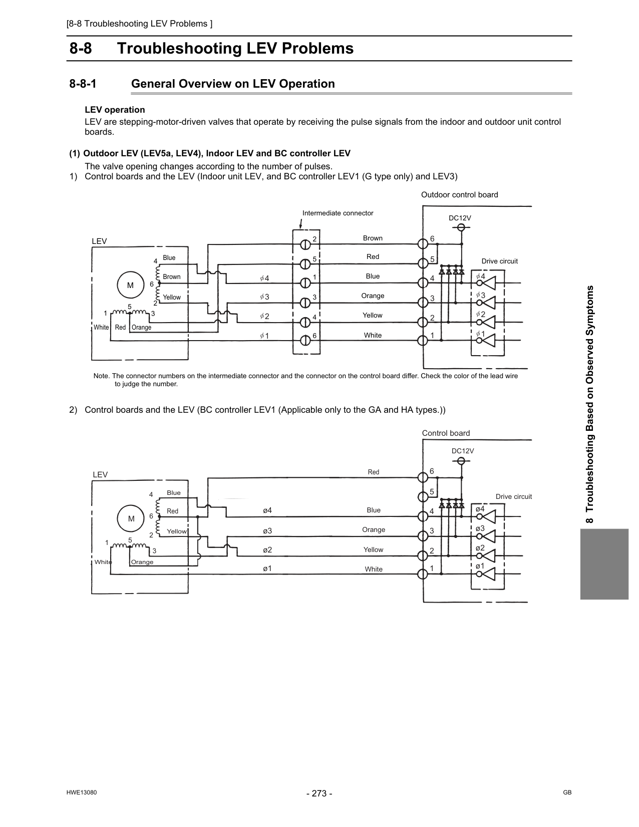
[8-8 Troubleshooting LEV Problems ]
Hwe13080
Gb
8 Troubleshooting Based on Observed Symptoms 8-8 Troubleshooting LEV Problems 8-8-1 General Overview on LEV Operation LEV operation LEV are stepping-motor-driven valves that operate by receiving the pulse signals from the indoor and outdoor unit control boards. (1) Outdoor LEV (LEV5a, LEV4), Indoor LEV and BC controller LEV The valve opening changes according to the number of pulses. 1) Control boards and the LEV (Indoor unit LEV, and BC controller LEV1 (G type only) and LEV3) 2) Control boards and the LEV (BC controller LEV1 (Applicable only to the GA and HA types.)) Note. The connector numbers on the intermediate connector and the connector on the control board differ. Check the color of the lead wire to judge the number. Outdoor control board Drive circuitLev
M
5 5 2 2 1 1 3 3 4 4 6 6Dc12V
Red Intermediate connector Brown Blue Orange Yellow White Red Orange White Brown Blue Yellow 6 5 4 4 3 2 1 3 2 1 4 3 2 1 ø4 ø3 ø2 ø1 ø4 ø3 ø2 ø1 Control board Drive circuitLev
M
5 2 1 3 4 6Dc12V
Red Blue Orange Yellow White Orange White Blue Yellow Red 6 5 4 3 2 1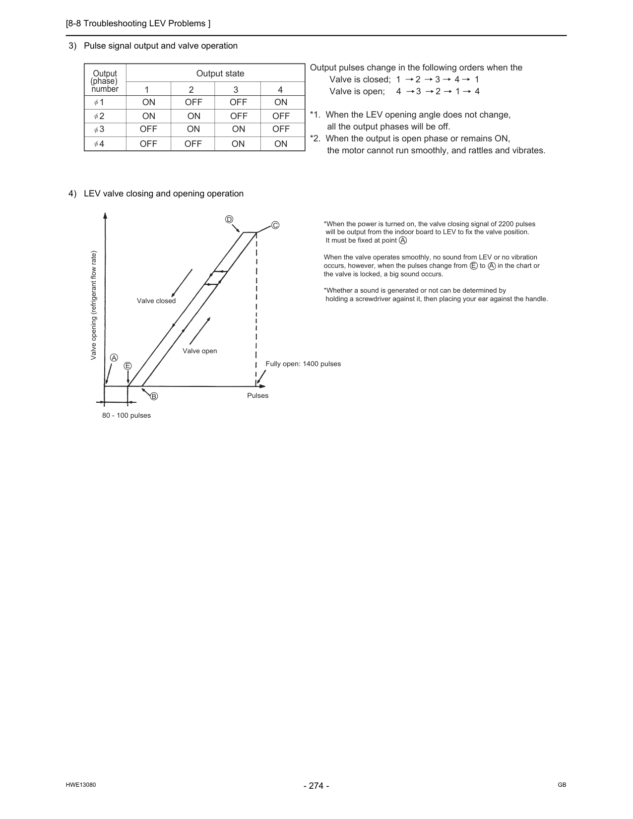
[8-8 Troubleshooting LEV Problems ]
Hwe13080
Gb
3) Pulse signal output and valve operation 4) LEV valve closing and opening operationOutput state Output (phase) number 1 2 3 4 1
On Off Off On
2On On Off Off
3Off On On Off
4Off Off On On
Output pulses change in the following orders when the Valve is closed; 1 2 3 4 1 Valve is open; 4 3 2 1 4 *1. When the LEV opening angle does not change, all the output phases will be off. *2. When the output is open phase or remains ON, the motor cannot run smoothly, and rattles and vibrates. *When the power is turned on, the valve closing signal of 2200 pulses will be output from the indoor board to LEV to fix the valve position. It must be fixed at point A. When the valve operates smoothly, no sound from LEV or no vibration occurs, however, when the pulses change from E to A in the chart or the valve is locked, a big sound occurs. *Whether a sound is generated or not can be determined by holding a screwdriver against it, then placing your ear against the handle. Valve opening (refrigerant flow rate) Valve closed Valve openE
B
80 - 100 pulses Pulses Fully open: 1400 pulsesA
C
D
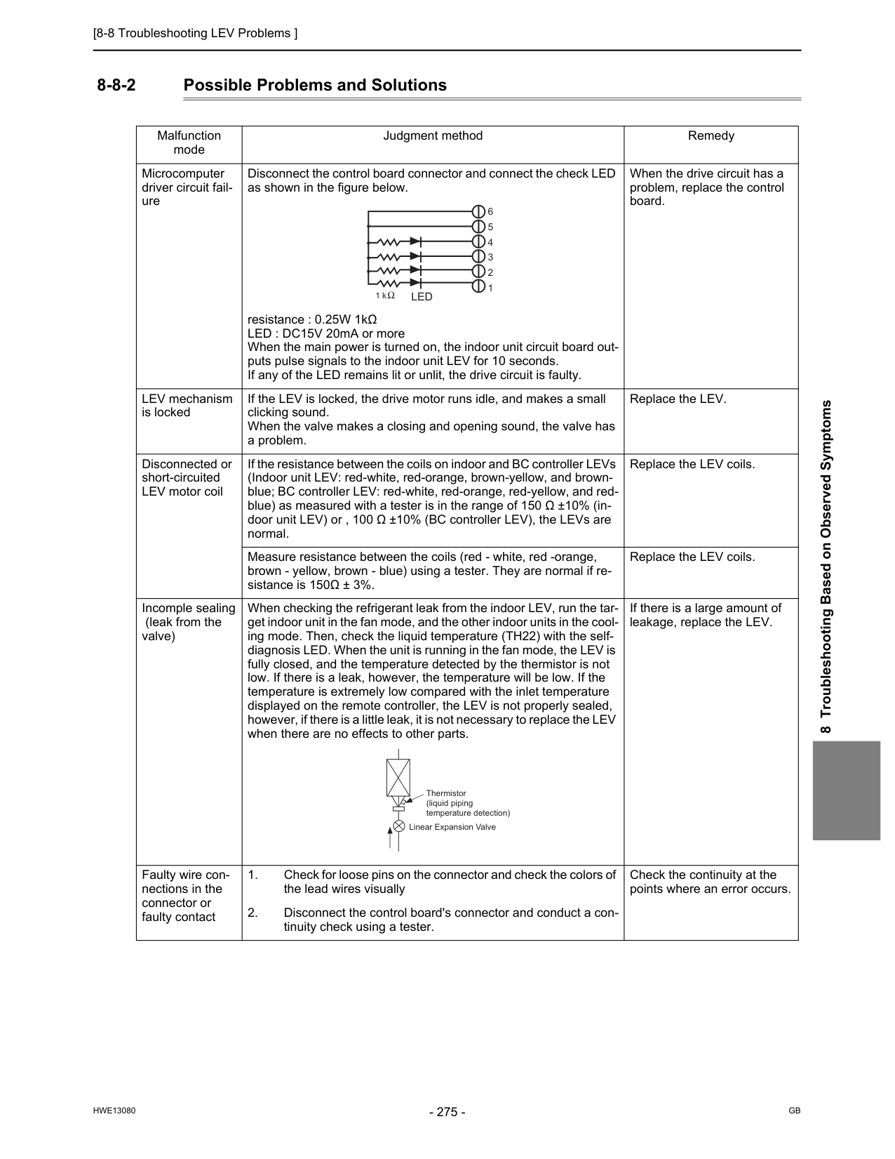
[8-8 Troubleshooting LEV Problems ]
Hwe13080
Gb
8 Troubleshooting Based on Observed Symptoms 8-8-2 Possible Problems and Solutions Malfunction mode Judgment method Remedy Microcomputer driver circuit fail- ure Disconnect the control board connector and connect the check LED as shown in the figure below. resistance : 0.25W 1kΩ LED : DC15V 20mA or more When the main power is turned on, the indoor unit circuit board out- puts pulse signals to the indoor unit LEV for 10 seconds. If any of the LED remains lit or unlit, the drive circuit is faulty. When the drive circuit has a problem, replace the control board. LEV mechanism is locked If the LEV is locked, the drive motor runs idle, and makes a small clicking sound. When the valve makes a closing and opening sound, the valve has a problem. Replace the LEV. Disconnected or short-circuited LEV motor coil If the resistance between the coils on indoor and BC controller LEVs (Indoor unit LEV: red-white, red-orange, brown-yellow, and brown- blue; BC controller LEV: red-white, red-orange, red-yellow, and red- blue) as measured with a tester is in the range of 150 Ω ±10% (in- door unit LEV) or , 100 Ω ±10% (BC controller LEV), the LEVs are normal. Replace the LEV coils. Measure resistance between the coils (red - white, red -orange, brown - yellow, brown - blue) using a tester. They are normal if re- sistance is 150Ω ± 3%. Replace the LEV coils. Incomple sealing (leak from the valve) When checking the refrigerant leak from the indoor LEV, run the tar- get indoor unit in the fan mode, and the other indoor units in the cool- ing mode. Then, check the liquid temperature (TH22) with the self- diagnosis LED. When the unit is running in the fan mode, the LEV is fully closed, and the temperature detected by the thermistor is not low. If there is a leak, however, the temperature will be low. If the temperature is extremely low compared with the inlet temperature displayed on the remote controller, the LEV is not properly sealed, however, if there is a little leak, it is not necessary to replace the LEV when there are no effects to other parts. If there is a large amount of leakage, replace the LEV. Faulty wire con- nections in the connector or faulty contactLed
Thermistor (liquid piping temperature detection) Linear Expansion Valve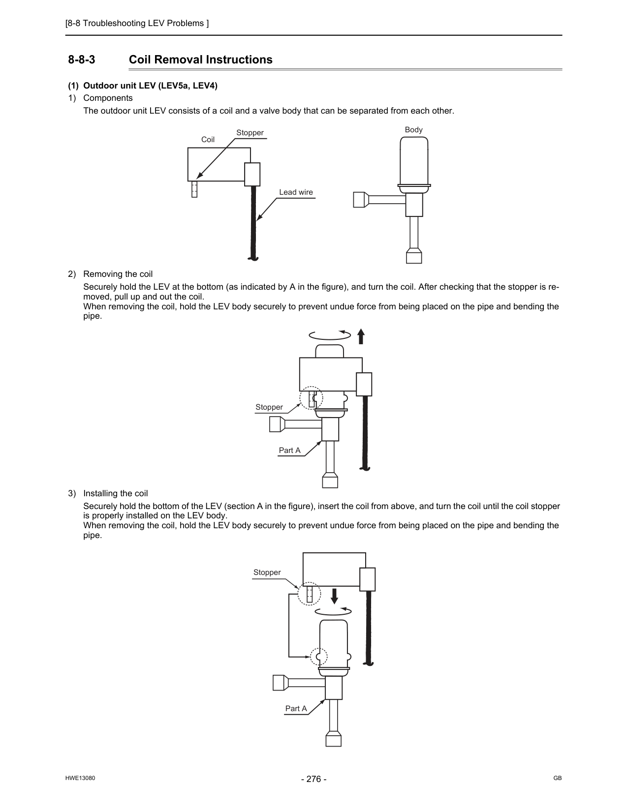
[8-8 Troubleshooting LEV Problems ]
Hwe13080
Gb
8-8-3 Coil Removal Instructions (1) Outdoor unit LEV (LEV5a, LEV4) 1) Components The outdoor unit LEV consists of a coil and a valve body that can be separated from each other. 2) Removing the coil Securely hold the LEV at the bottom (as indicated by A in the figure), and turn the coil. After checking that the stopper is re- moved, pull up and out the coil. When removing the coil, hold the LEV body securely to prevent undue force from being placed on the pipe and bending the pipe. 3) Installing the coil Securely hold the bottom of the LEV (section A in the figure), insert the coil from above, and turn the coil until the coil stopper is properly installed on the LEV body. When removing the coil, hold the LEV body securely to prevent undue force from being placed on the pipe and bending the pipe. Stopper Lead wire Coil Body Part A Stopper Stopper Part A
[8-9 Troubleshooting Problems with Major Components on BC Controller ]
Hwe13080
Gb
8 Troubleshooting Based on Observed Symptoms 8-9 Troubleshooting Problems with Major Components on BC Controller 8-9-1 Pressure Sensor Troubleshooting flow chart for pressure sensor Check whether the pressure sensor or the connectors of P1 and P3 are connected, properly All the compressors of the outdoor units to which the BC controller is connected are stopped. Check P1 and P3 on the self-diagnosis LED, and check that the detected pressure is 0.098MPa [14psi] or less. On the self-diagnosis monitor, measure Outdoor high-pressure 63HS1 Outdoor low-pressure 63LS BC controller pressure P1 (liquid side) and P3 (intermediate part) Check whether the result is63Hs1 P1 P3 63Ls
Start
Repair the fault. Fix the relation between the refrigerant piping and the transmission line. Fix the relation between the refrigerant piping and the transmission line. Replace the pressure sensor. Replace the board. Restore contact failure. Check whether the contact of the pressure sensor connector in trouble is not faulty.Ok?
Ok?
Check that the difference between each detected pressure is 0.098MPa [14psi] or less.Ok?
Both the board and the pressure sensor are normal.Ok?
Is Pd P1 P3 Ps? Remove the pressure sensor connector from the board, and check the pressure.Ok?
Ok?
Check whether the refrigerant pipe and the transmission line are connected correctly between the indoor unit and the BC controller.Ok?
Operating at the moment? Check whether the refrigerant pipe and the transmission line are connected correctly between the indoor unit and the BC controller.Ok?
Yes
Note 2 Note 1No
Yes
Yes
Yes
Note 3 Note 4No
No
No
No
Yes
No
No
Yes
Yes
Yes
No
No
Yes
No
Yes
No
No
Replace the pressure sensor, which detects less than 6MPa [870psi] pressure, with the pressure sensor, which detects 6MPa [870psi] or more pressure, check the pressure, and check whether the detected pressure is displayed normally. 10 minutes or longer after the operation stops? Pressure 0MPa [0psi] 6MPa [870psi] pressure or more is displayed. Short-circuit between connecter pins #2 and #3 on the circuit board, and check the pressure.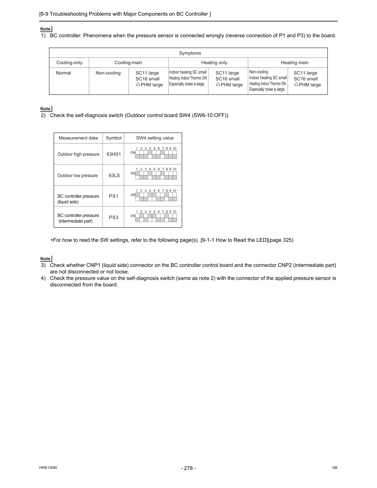
[8-9 Troubleshooting Problems with Major Components on BC Controller ]
Hwe13080
Gb
1) BC controller: Phenomena when the pressure sensor is connected wrongly (reverse connection of P1 and P3) to the board. 2) Check the self-diagnosis switch (Outdoor control board SW4 (SW6-10:OFF)). 3) Check whether CNP1 (liquid side) connector on the BC controller control board and the connector CNP2 (intermediate part) are not disconnected or not loose. 4) Check the pressure value on the self-diagnosis switch (same as note 2) with the connector of the applied pressure sensor is disconnected from the board. Cooling-only Heating onlyHeating main Non-cooling Indoor heating SC small
Heating indoor Thermo ON Especially noise is large. Indoor heating SC small Heating indoor Thermo ON Especially noise is large. Cooling-main Symptoms SC11 large
SC16 small
PHM large
SC11 large
SC16 small
PHM large
Non-cooling Normal SC11 large SC16 small PHM large For how to read the SW settings, refer to the following page(s). [9-1-1 How to Read the LED](page 325) Measurement data SW4 setting value Outdoor high pressure Outdoor low pressure BC controller pressure (liquid side) BC controller pressure (intermediate part)
Symbol
63Hs1
Ps1
63Ls
Ps3
1 2 3 4 5 6 7 8 9 10On
1 2 3 4 5 6 7 8 9 10On
1 2 3 4 5 6 7 8 9 10On
1 2 3 4 5 6 7 8 9 10On
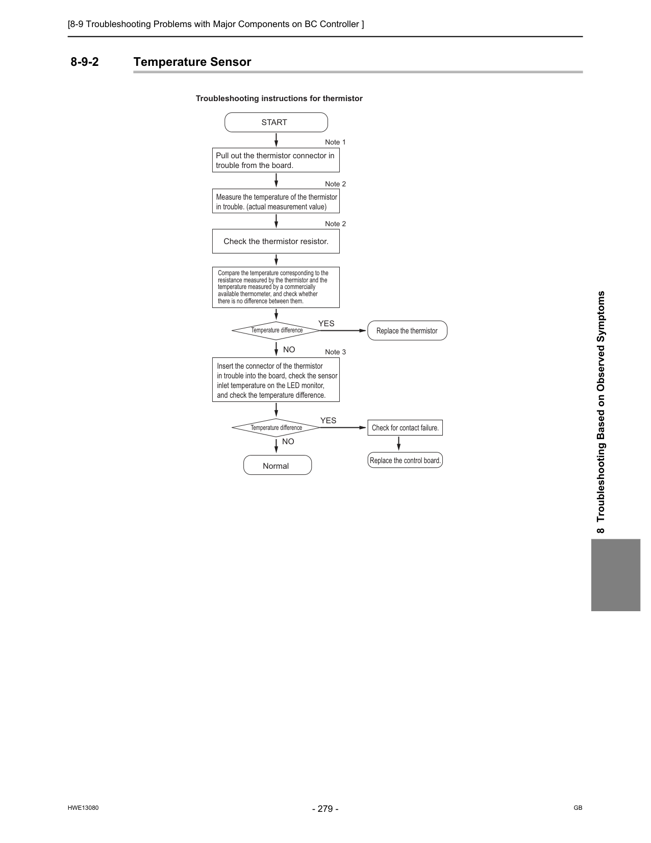
[8-9 Troubleshooting Problems with Major Components on BC Controller ]
Hwe13080
Gb
8 Troubleshooting Based on Observed Symptoms 8-9-2 Temperature Sensor Pull out the thermistor connector in trouble from the board. Measure the temperature of the thermistor in trouble. (actual measurement value) Check the thermistor resistor. Compare the temperature corresponding to the resistance measured by the thermistor and the temperature measured by a commercially available thermometer, and check whether there is no difference between them. Insert the connector of the thermistor in trouble into the board, check the sensor inlet temperature on the LED monitor, and check the temperature difference.Start
Normal Troubleshooting instructions for thermistor Replace the thermistor Temperature difference Temperature difference Check for contact failure. Replace the control board. Note 1 Note 2 Note 2 Note 3Yes
No
Yes
No
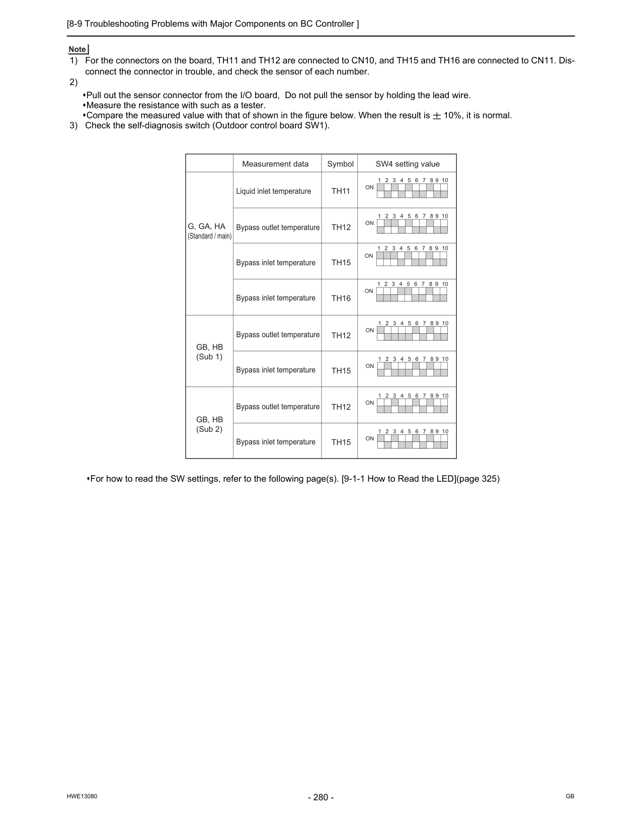
[8-9 Troubleshooting Problems with Major Components on BC Controller ]
Hwe13080
Gb
1) For the connectors on the board, TH11 and TH12 are connected to CN10, and TH15 and TH16 are connected to CN11. Dis- connect the connector in trouble, and check the sensor of each number. 2) Pull out the sensor connector from the I/O board, Do not pull the sensor by holding the lead wire. Measure the resistance with such as a tester. Compare the measured value with that of shown in the figure below. When the result is 10%, it is normal. 3) Check the self-diagnosis switch (Outdoor control board SW1). For how to read the SW settings, refer to the following page(s). [9-1-1 How to Read the LED](page 325) 1 2 3 4 5 6 7 8 9 10On
1 2 3 4 5 6 7 8 9 10On
1 2 3 4 5 6 7 8 9 10On
1 2 3 4 5 6 7 8 9 10On
1 2 3 4 5 6 7 8 9 10On
1 2 3 4 5 6 7 8 9 10On
1 2 3 4 5 6 7 8 9 10On
1 2 3 4 5 6 7 8 9 10On
Th12
Th15
Th12
Th15
Liquid inlet temperature Bypass outlet temperature Bypass outlet temperature Bypass outlet temperatureTh11
Th12
Bypass inlet temperature Bypass inlet temperature Bypass inlet temperature Bypass inlet temperatureTh15
Th16
Measurement data SW4 setting value SymbolG, Ga, Ha
(Standard / main)Gb, Hb
(Sub 1)Gb, Hb
(Sub 2)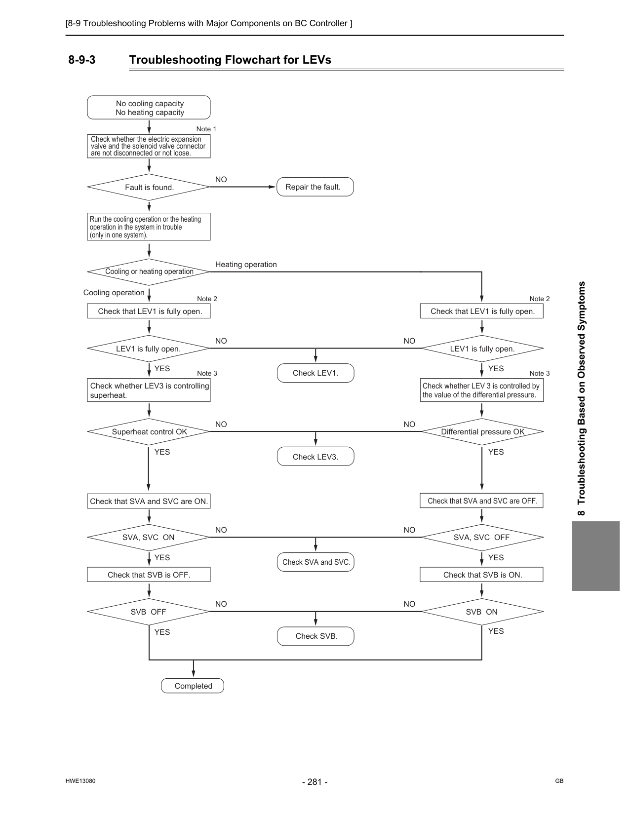
[8-9 Troubleshooting Problems with Major Components on BC Controller ]
Hwe13080
Gb
8 Troubleshooting Based on Observed Symptoms 8-9-3 Troubleshooting Flowchart for LEVs Check whether the electric expansion valve and the solenoid valve connector are not disconnected or not loose. Run the cooling operation or the heating operation in the system in trouble (only in one system). No cooling capacity No heating capacity Repair the fault. Fault is found. Note 1No
Check that LEV1 is fully open. Check that LEV1 is fully open. Check that SVA and SVC are ON. Check that SVA and SVC are OFF. Cooling or heating operation Note 2 Heating operation Check whether LEV3 is controlling superheat. Check LEV1. Check LEV3. Check SVA and SVC. Check SVB. LEV1 is fully open. Check whether LEV 3 is controlled by the value of the differential pressure. LEV1 is fully open. Note 3 Note 2 Note 3Yes
No
Cooling operation Superheat control OK Differential pressure OKYes
No
Check that SVB is OFF. Check that SVB is ON.Sva, Svc On
Sva, Svc Off
Yes
Yes
No
CompletedSvb Off
Svb On
Yes
Yes
Yes
Yes
No
No
No
No
No
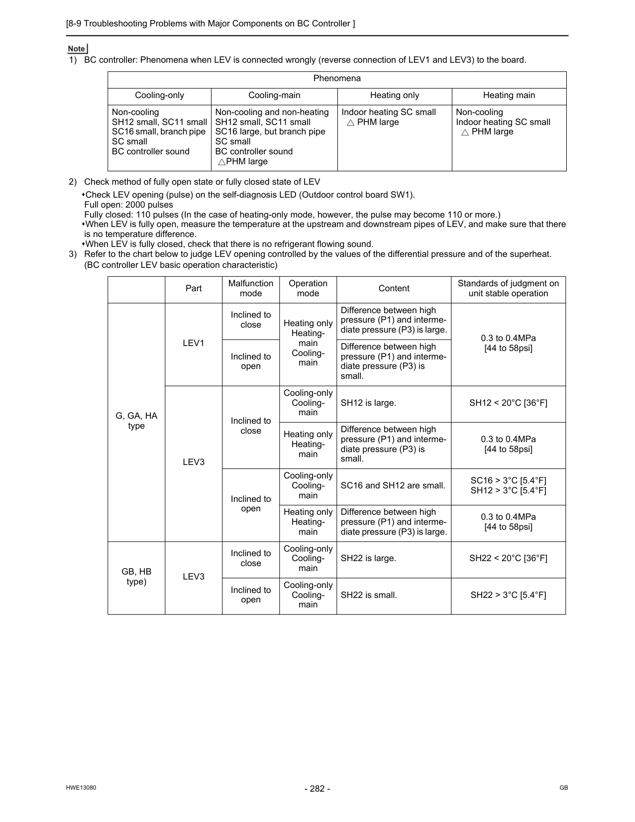
[8-9 Troubleshooting Problems with Major Components on BC Controller ]
Hwe13080
Gb
1) BC controller: Phenomena when LEV is connected wrongly (reverse connection of LEV1 and LEV3) to the board. 2) Check method of fully open state or fully closed state of LEV Check LEV opening (pulse) on the self-diagnosis LED (Outdoor control board SW1). Full open: 2000 pulses Fully closed: 110 pulses (In the case of heating-only mode, however, the pulse may become 110 or more.) When LEV is fully open, measure the temperature at the upstream and downstream pipes of LEV, and make sure that there is no temperature difference. When LEV is fully closed, check that there is no refrigerant flowing sound. 3) Refer to the chart below to judge LEV opening controlled by the values of the differential pressure and of the superheat. (BC controller LEV basic operation characteristic) Phenomena Cooling-only Cooling-main Heating only Heating main Non-cooling SH12 small, SC11 small SC16 small, branch pipe SC small BC controller sound Non-cooling and non-heating SH12 small, SC11 small SC16 large, but branch pipe SC small BC controller soundPHM large Indoor heating SC small
PHM large Non-cooling Indoor heating SC small
PHM large Part Malfunction mode Operation mode Content Standards of judgment on unit stable operation
G, Ga, Ha
typeLev1
Inclined to close Heating only Heating- main Cooling- main Difference between high pressure (P1) and interme- diate pressure (P3) is large. 0.3 to 0.4MPa [44 to 58psi] Inclined to open Difference between high pressure (P1) and interme- diate pressure (P3) is small.Lev3
Inclined to close Cooling-only Cooling- main SH12 is large.Sh12 < 20°C [36°F]
Heating only Heating- main Difference between high pressure (P1) and interme- diate pressure (P3) is small. 0.3 to 0.4MPa [44 to 58psi] Inclined to open Cooling-only Cooling- main SC16 and SH12 are small.Sc16 > 3°C [5.4°F]
Sh12 > 3°C [5.4°F]
Heating only Heating- main Difference between high pressure (P1) and interme- diate pressure (P3) is large. 0.3 to 0.4MPa [44 to 58psi]Gb, Hb
type)Lev3
Inclined to close Cooling-only Cooling- main SH22 is large.Sh22 < 20°C [36°F]
Inclined to open Cooling-only Cooling- main SH22 is small.Sh22 > 3°C [5.4°F]
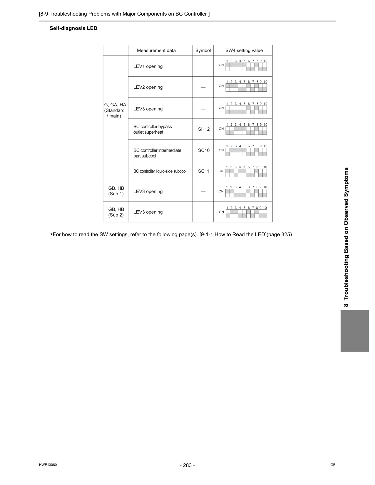
[8-9 Troubleshooting Problems with Major Components on BC Controller ]
Hwe13080
Gb
8 Troubleshooting Based on Observed Symptoms Self-diagnosis LED For how to read the SW settings, refer to the following page(s). [9-1-1 How to Read the LED](page 325) 1 2 3 4 5 6 7 8 9 10On
1 2 3 4 5 6 7 8 9 10On
1 2 3 4 5 6 7 8 9 10On
1 2 3 4 5 6 7 8 9 10On
1 2 3 4 5 6 7 8 9 10On
1 2 3 4 5 6 7 8 9 10On
1 2 3 4 5 6 7 8 9 10On
1 2 3 4 5 6 7 8 9 10On
LEV1 opening LEV3 opening LEV3 opening BC controller bypass outlet superheat BC controller intermediate part subcoolSh12
LEV2 opening LEV3 openingSc16
BC controller liquid-side subcoolSc11
Measurement data SW4 setting value SymbolG, Ga, Ha
(Standard / main)Gb, Hb
(Sub 1)Gb, Hb
(Sub 2)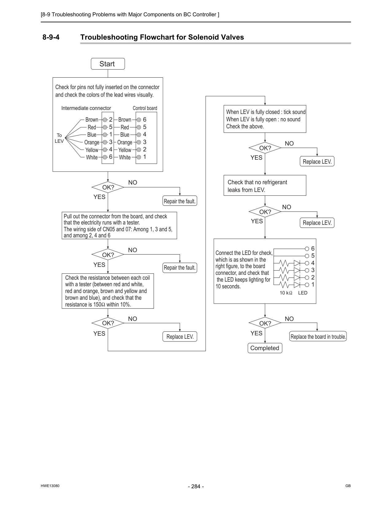
[8-9 Troubleshooting Problems with Major Components on BC Controller ]
Hwe13080
Gb
8-9-4 Troubleshooting Flowchart for Solenoid Valves 6 6 5 4 3 2 1 5 4 3 2 1 2 5 1 3 4 6 ToLev
Led
10 k Start Brown Red Blue Orange Yellow White Brown Red Blue Orange Yellow WhiteOk?
No
Yes
Ok?
No
Yes
Repair the fault. Repair the fault.Ok?
No
Yes
Ok?
No
Yes
Replace LEV.Ok?
No
Yes
Replace LEV. Replace LEV.Ok?
No
Yes
Replace the board in trouble. Completed Check for pins not fully inserted on the connector and check the colors of the lead wires visually. Intermediate connector Control board Check that no refrigerant leaks from LEV. Pull out the connector from the board, and check that the electricity runs with a tester. The wiring side of CN05 and 07: Among 1, 3 and 5, and among 2, 4 and 6 Check the resistance between each coil with a tester (between red and white, red and orange, brown and yellow and brown and blue), and check that the resistance is 150 within 10%. Connect the LED for check, which is as shown in the right figure, to the board connector, and check that the LED keeps lighting for 10 seconds. When LEV is fully closed : tick sound When LEV is fully open : no sound Check the above.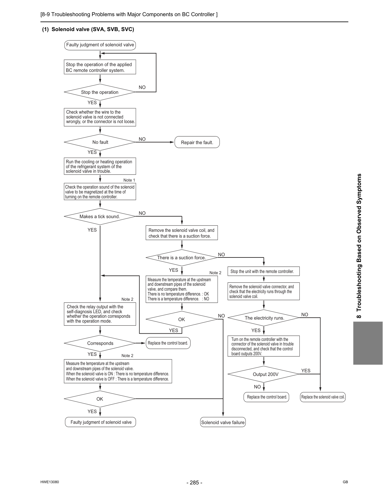
[8-9 Troubleshooting Problems with Major Components on BC Controller ]
Hwe13080
Gb
8 Troubleshooting Based on Observed Symptoms (1) Solenoid valve (SVA, SVB, SVC) Stop the operation of the applied BC remote controller system. Faulty judgment of solenoid valveFaulty judgment of solenoid valve Solenoid valve failure
Replace the control board.
Replace the solenoid valve coil. Repair the fault. Replace the control board. Stop the operation Note 1 Check whether the wire to the solenoid valve is not connected wrongly, or the connector is not loose.
No fault Check the operation sound of the solenoid valve to be magnetized at the time of turning on the remote controller. Makes a tick sound. Check the relay output with the self-diagnosis LED, and check whether the operation corresponds with the operation mode.
Corresponds Measure the temperature at the upstream and downstream pipes of the solenoid valve. When the solenoid valve is ON : There is no temperature difference. When the solenoid valve is OFF : There is a temperature difference.
Ok
Remove the solenoid valve coil, and check that there is a suction force. There is a suction force. Note 2 Note 2 Note 2 Measure the temperature at the upstream and downstream pipes of the solenoid valve, and compare them. There is no temperature difference. : OK There is a temperature difference. : NOOk
Run the cooling or heating operation of the refrigerant system of the solenoid valve in trouble.No
No
No
Stop the unit with the remote controller. Remove the solenoid valve connector, and check that the electricity runs through the solenoid valve coil.The electricity runs.
Output 200V
No
No
No
No
Yes
Yes
Yes
Yes
Yes
Yes
Yes
Yes
Yes
Turn on the remote controller with the connector of the solenoid valve in trouble disconnected, and check that the control board outputs 200V.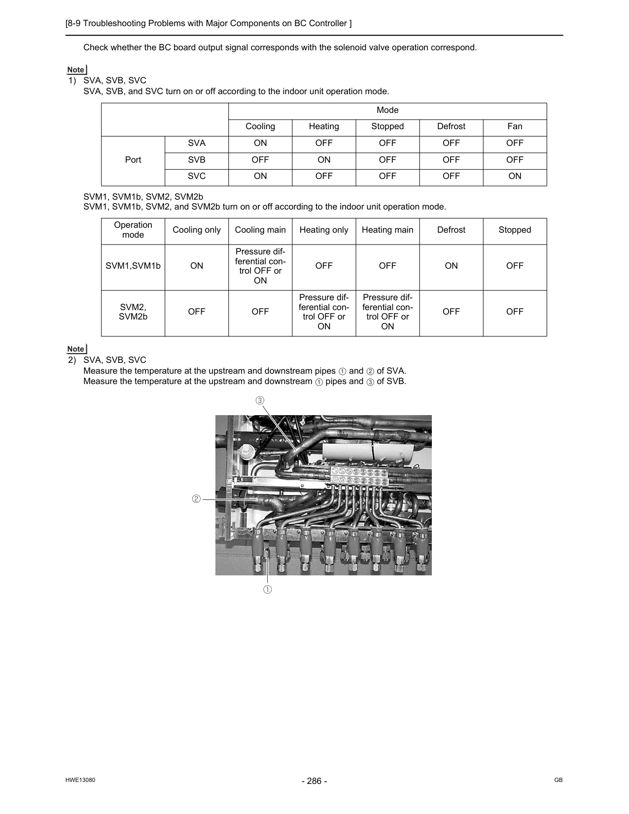
[8-9 Troubleshooting Problems with Major Components on BC Controller ]
Hwe13080
Gb
Check whether the BC board output signal corresponds with the solenoid valve operation correspond.1) Sva, Svb, Svc
SVA, SVB, and SVC turn on or off according to the indoor unit operation mode. SVM1, SVM1b, SVM2, SVM2b SVM1, SVM1b, SVM2, and SVM2b turn on or off according to the indoor unit operation mode.2) Sva, Svb, Svc
Measure the temperature at the upstream and downstream pipes and of SVA. Measure the temperature at the upstream and downstream pipes and of SVB. Mode Cooling Heating Stopped Defrost Fan PortSva
On
Off
Off
Off
Off
Svb
Off
On
Off
Off
Off
Svc
On
Off
Off
Off
On
Operation mode Cooling only Cooling main Heating only Heating main Defrost Stopped SVM1,SVM1bOn
Pressure dif- ferential con- trol OFF orOn
Off
Off
On
Off
Svm2,
SVM2bOff
Off
Pressure dif- ferential con- trol OFF orOn
Pressure dif- ferential con- trol OFF orOn
Off
Off
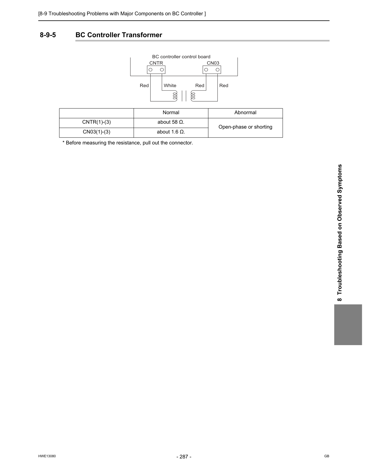
[8-9 Troubleshooting Problems with Major Components on BC Controller ]
Hwe13080
Gb
8 Troubleshooting Based on Observed Symptoms 8-9-5 BC Controller TransformerCntr(1)-(3)
about 58 Ω. Open-phase or shortingCn03(1)-(3)
about 1.6 Ω.Cntr
Cn03
BC controller control board Red White Red Red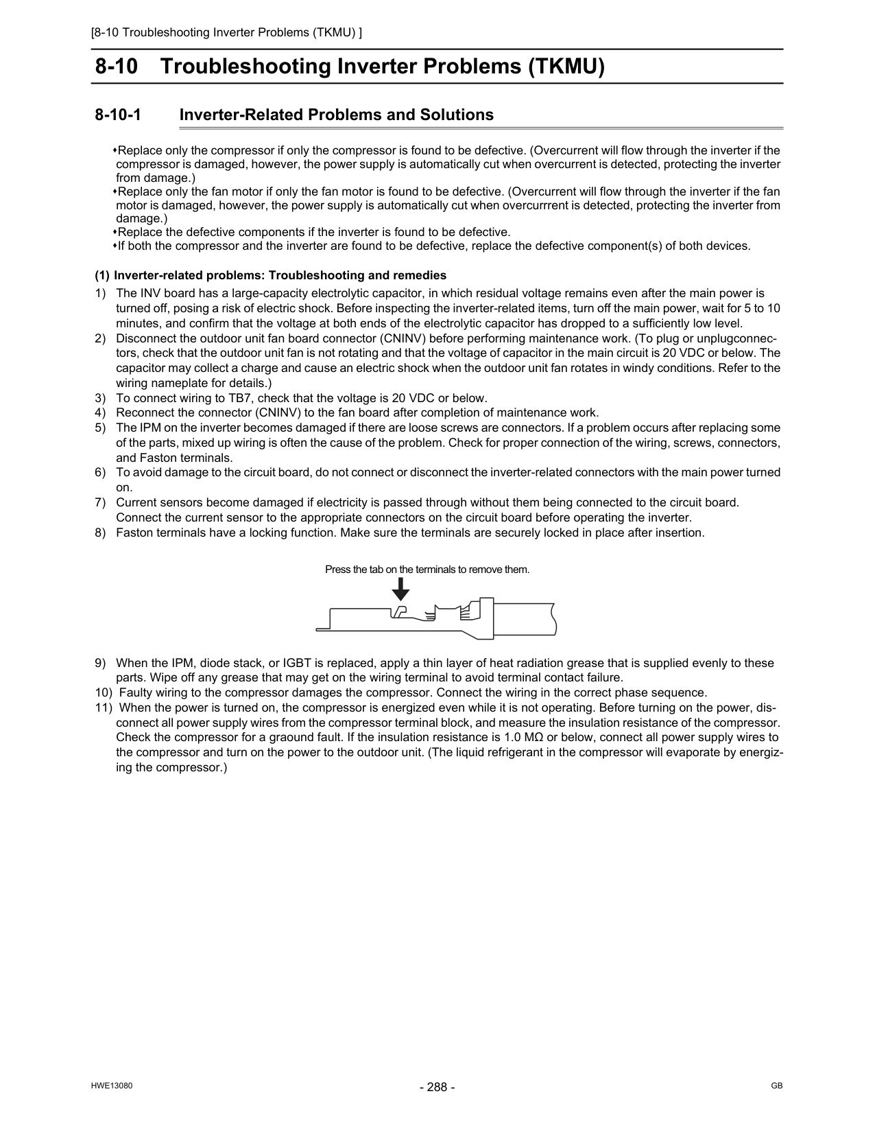
[8-10 Troubleshooting Inverter Problems (TKMU) ]
Hwe13080
Gb
8-10 Troubleshooting Inverter Problems (TKMU) 8-10-1 Inverter-Related Problems and Solutions Replace only the compressor if only the compressor is found to be defective. (Overcurrent will flow through the inverter if the compressor is damaged, however, the power supply is automatically cut when overcurrent is detected, protecting the inverter from damage.) Replace only the fan motor if only the fan motor is found to be defective. (Overcurrent will flow through the inverter if the fan motor is damaged, however, the power supply is automatically cut when overcurrrent is detected, protecting the inverter from damage.) Replace the defective components if the inverter is found to be defective. If both the compressor and the inverter are found to be defective, replace the defective component(s) of both devices. (1) Inverter-related problems: Troubleshooting and remedies 1) The INV board has a large-capacity electrolytic capacitor, in which residual voltage remains even after the main power is turned off, posing a risk of electric shock. Before inspecting the inverter-related items, turn off the main power, wait for 5 to 10 minutes, and confirm that the voltage at both ends of the electrolytic capacitor has dropped to a sufficiently low level. 2) Disconnect the outdoor unit fan board connector (CNINV) before performing maintenance work. (To plug or unplugconnec- tors, check that the outdoor unit fan is not rotating and that the voltage of capacitor in the main circuit is 20 VDC or below. The capacitor may collect a charge and cause an electric shock when the outdoor unit fan rotates in windy conditions. Refer to the wiring nameplate for details.) 3) To connect wiring to TB7, check that the voltage is 20 VDC or below. 4) Reconnect the connector (CNINV) to the fan board after completion of maintenance work. 5) The IPM on the inverter becomes damaged if there are loose screws are connectors. If a problem occurs after replacing some of the parts, mixed up wiring is often the cause of the problem. Check for proper connection of the wiring, screws, connectors, and Faston terminals. 6) To avoid damage to the circuit board, do not connect or disconnect the inverter-related connectors with the main power turned on. 7) Current sensors become damaged if electricity is passed through without them being connected to the circuit board. Connect the current sensor to the appropriate connectors on the circuit board before operating the inverter. 8) Faston terminals have a locking function. Make sure the terminals are securely locked in place after insertion. 9) When the IPM, diode stack, or IGBT is replaced, apply a thin layer of heat radiation grease that is supplied evenly to these parts. Wipe off any grease that may get on the wiring terminal to avoid terminal contact failure. 10) Faulty wiring to the compressor damages the compressor. Connect the wiring in the correct phase sequence. 11) When the power is turned on, the compressor is energized even while it is not operating. Before turning on the power, dis- connect all power supply wires from the compressor terminal block, and measure the insulation resistance of the compressor. Check the compressor for a graound fault. If the insulation resistance is 1.0 MΩ or below, connect all power supply wires to the compressor and turn on the power to the outdoor unit. (The liquid refrigerant in the compressor will evaporate by energiz- ing the compressor.) Press the tab on the terminals to remove them.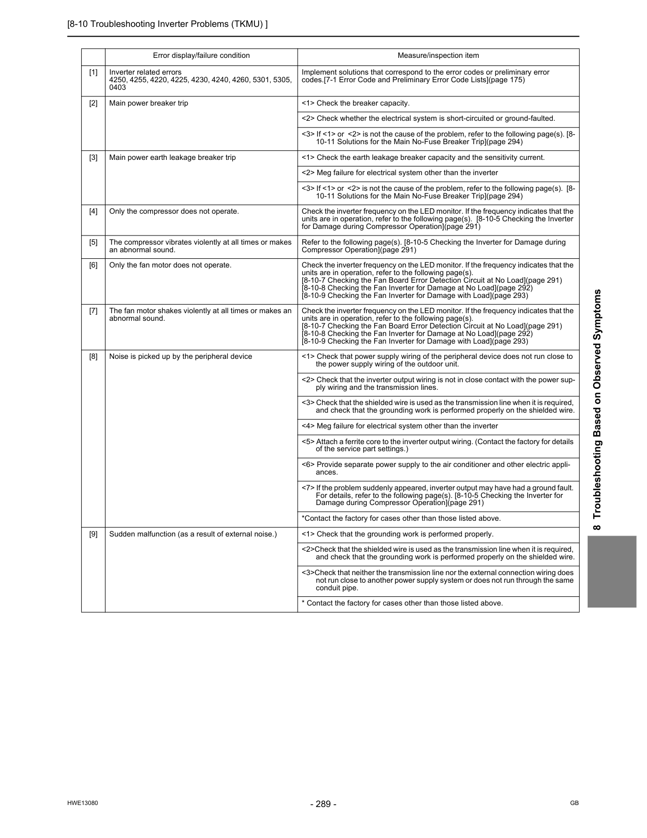
[8-10 Troubleshooting Inverter Problems (TKMU) ]
Hwe13080
Gb
8 Troubleshooting Based on Observed Symptoms Error display/failure condition Measure/inspection item [1] Inverter related errors 4250, 4255, 4220, 4225, 4230, 4240, 4260, 5301, 5305, 0403 Implement solutions that correspond to the error codes or preliminary error codes.[7-1 Error Code and Preliminary Error Code Lists](page 175) [2] Main power breaker trip <1> Check the breaker capacity. <2> Check whether the electrical system is short-circuited or ground-faulted. <3> If <1> or <2> is not the cause of the problem, refer to the following page(s). [8- 10-11 Solutions for the Main No-Fuse Breaker Trip](page 294) [3] Main power earth leakage breaker trip <1> Check the earth leakage breaker capacity and the sensitivity current. <2> Meg failure for electrical system other than the inverter <3> If <1> or <2> is not the cause of the problem, refer to the following page(s). [8- 10-11 Solutions for the Main No-Fuse Breaker Trip](page 294) [4] Only the compressor does not operate. Check the inverter frequency on the LED monitor. If the frequency indicates that the units are in operation, refer to the following page(s). [8-10-5 Checking the Inverter for Damage during Compressor Operation](page 291) [5] The compressor vibrates violently at all times or makes an abnormal sound. Refer to the following page(s). [8-10-5 Checking the Inverter for Damage during Compressor Operation](page 291) [6] Only the fan motor does not operate. Check the inverter frequency on the LED monitor. If the frequency indicates that the units are in operation, refer to the following page(s). [8-10-7 Checking the Fan Board Error Detection Circuit at No Load](page 291) [8-10-8 Checking the Fan Inverter for Damage at No Load](page 292) [8-10-9 Checking the Fan Inverter for Damage with Load](page 293) [7] The fan motor shakes violently at all times or makes an abnormal sound. Check the inverter frequency on the LED monitor. If the frequency indicates that the units are in operation, refer to the following page(s). [8-10-7 Checking the Fan Board Error Detection Circuit at No Load](page 291) [8-10-8 Checking the Fan Inverter for Damage at No Load](page 292) [8-10-9 Checking the Fan Inverter for Damage with Load](page 293) [8] Noise is picked up by the peripheral device <1> Check that power supply wiring of the peripheral device does not run close to the power supply wiring of the outdoor unit. <2> Check that the inverter output wiring is not in close contact with the power sup- ply wiring and the transmission lines. <3> Check that the shielded wire is used as the transmission line when it is required, and check that the grounding work is performed properly on the shielded wire. <4> Meg failure for electrical system other than the inverter <5> Attach a ferrite core to the inverter output wiring. (Contact the factory for details of the service part settings.) <6> Provide separate power supply to the air conditioner and other electric appli- ances. <7> If the problem suddenly appeared, inverter output may have had a ground fault. For details, refer to the following page(s). [8-10-5 Checking the Inverter for Damage during Compressor Operation](page 291) *Contact the factory for cases other than those listed above. [9] Sudden malfunction (as a result of external noise.) <1> Check that the grounding work is performed properly. <2>Check that the shielded wire is used as the transmission line when it is required, and check that the grounding work is performed properly on the shielded wire. <3>Check that neither the transmission line nor the external connection wiring does not run close to another power supply system or does not run through the same conduit pipe.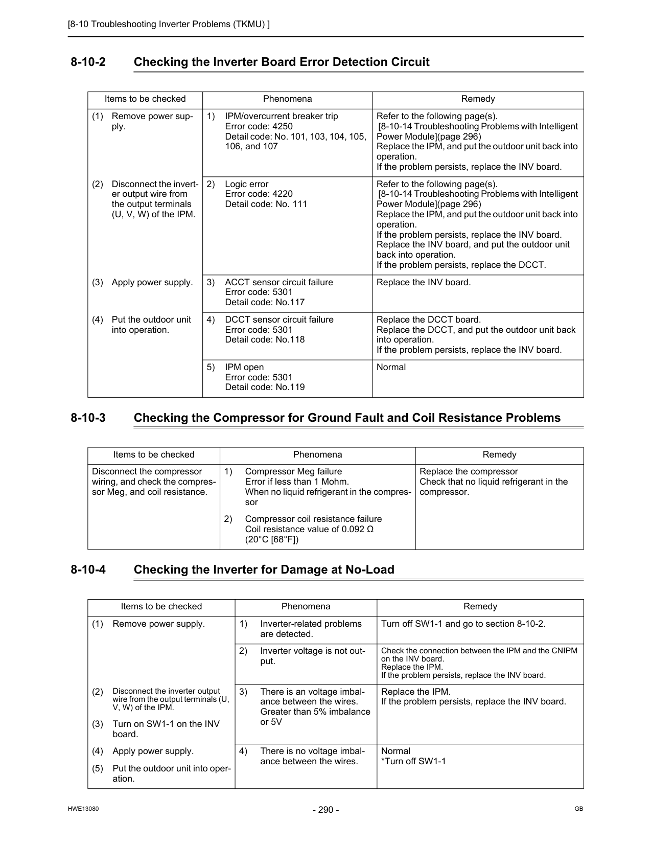
[8-10 Troubleshooting Inverter Problems (TKMU) ]
Hwe13080
Gb
8-10-2 Checking the Inverter Board Error Detection Circuit 8-10-3 Checking the Compressor for Ground Fault and Coil Resistance Problems 8-10-4 Checking the Inverter for Damage at No-Load Items to be checked Phenomena Remedy (1) Remove power sup- ply. 1) IPM/overcurrent breaker trip Error code: 4250 Detail code: No. 101, 103, 104, 105, 106, and 107 Refer to the following page(s). [8-10-14 Troubleshooting Problems with Intelligent Power Module](page 296) Replace the IPM, and put the outdoor unit back into operation. If the problem persists, replace the INV board. (2) Disconnect the invert- er output wire from the output terminals (U, V, W) of the IPM. 2) Logic error Error code: 4220 Detail code: No. 111 Refer to the following page(s). [8-10-14 Troubleshooting Problems with Intelligent Power Module](page 296) Replace the IPM, and put the outdoor unit back into operation. If the problem persists, replace the INV board. Replace the INV board, and put the outdoor unit back into operation. If the problem persists, replace the DCCT. (3) Apply power supply. 3) ACCT sensor circuit failure Error code: 5301 Detail code: No.117 Replace the INV board. (4) Put the outdoor unit into operation. 4) DCCT sensor circuit failure Error code: 5301 Detail code: No.118 Replace the DCCT board. Replace the DCCT, and put the outdoor unit back into operation. If the problem persists, replace the INV board. 5) IPM open Error code: 5301 Detail code: No.119 Normal Items to be checked Phenomena Remedy Disconnect the compressor wiring, and check the compres- sor Meg, and coil resistance. 1) Compressor Meg failure Error if less than 1 Mohm. When no liquid refrigerant in the compres- sor Replace the compressor Check that no liquid refrigerant in the compressor. 2) Compressor coil resistance failure Coil resistance value of 0.092 Ω(20°C [68°F])
Items to be checked Phenomena Remedy (1) Remove power supply. 1) Inverter-related problems are detected. Turn off SW1-1 and go to section 8-10-2. 2) Inverter voltage is not out- put. Check the connection between the IPM and the CNIPM on the INV board. Replace the IPM. If the problem persists, replace the INV board. (2) Disconnect the inverter output wire from the output terminals (U, V, W) of the IPM. 3) There is an voltage imbal- ance between the wires. Greater than 5% imbalance or 5V Replace the IPM. If the problem persists, replace the INV board. (3) Turn on SW1-1 on the INV board. (4) Apply power supply. 4) There is no voltage imbal- ance between the wires. Normal *Turn off SW1-1 (5) Put the outdoor unit into oper- ation.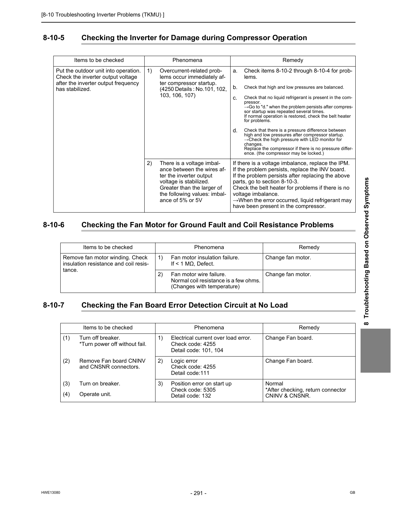
[8-10 Troubleshooting Inverter Problems (TKMU) ]
Hwe13080
Gb
8 Troubleshooting Based on Observed Symptoms 8-10-5 Checking the Inverter for Damage during Compressor Operation 8-10-6 Checking the Fan Motor for Ground Fault and Coil Resistance Problems 8-10-7 Checking the Fan Board Error Detection Circuit at No Load Items to be checked Phenomena Remedy Put the outdoor unit into operation. Check the inverter output voltage after the inverter output frequency has stabilized. 1) Overcurrent-related prob- lems occur immediately af- ter compressor startup. (4250 Details : No.101, 102, 103, 106, 107) a. Check items 8-10-2 through 8-10-4 for prob- lems. b. Check that high and low pressures are balanced. c. Check that no liquid refrigerant is present in the com- pressor. →Go to "d." when the problem persists after compres- sor startup was repeated several times. If normal operation is restored, check the belt heater for problems. d. Check that there is a pressure difference between high and low pressures after compressor startup. →Check the high pressure with LED monitor for changes. Replace the compressor if there is no pressure differ- ence. (the compressor may be locked.) 2) There is a voltage imbal- ance between the wires af- ter the inverter output voltage is stabilized. Greater than the larger of the following values: imbal- ance of 5% or 5V If there is a voltage imbalance, replace the IPM. If the problem persists, replace the INV board. If the problem persists after replacing the above parts, go to section 8-10-3. Check the belt heater for problems if there is no voltage imbalance. →When the error occurred, liquid refrigerant may have been present in the compressor. Items to be checked Phenomena Remedy Remove fan motor winding. Check insulation resistance and coil resis- tance. 1) Fan motor insulation failure. If < 1 MΩ, Defect. Change fan motor. 2) Fan motor wire failure. Normal coil resistance is a few ohms. (Changes with temperature) Change fan motor. Items to be checked Phenomena Remedy (1) Turn off breaker. *Turn power off without fail. 1) Electrical current over load error. Check code: 4255 Detail code: 101, 104 Change Fan board. (2) Remove Fan board CNINV and CNSNR connectors. 2) Logic error Check code: 4255 Detail code:111 Change Fan board. (3) Turn on breaker. 3) Position error on start up Check code: 5305 Detail code: 132 Normal *After checking, return connectorCninv & Cnsnr.
(4) Operate unit.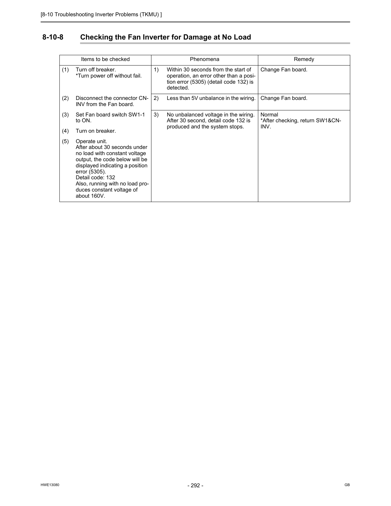
[8-10 Troubleshooting Inverter Problems (TKMU) ]
Hwe13080
Gb
8-10-8 Checking the Fan Inverter for Damage at No Load Items to be checked Phenomena Remedy (1) Turn off breaker. *Turn power off without fail. 1) Within 30 seconds from the start of operation, an error other than a posi- tion error (5305) (detail code 132) is detected. Change Fan board. (2) Disconnect the connector CN- INV from the Fan board. 2) Less than 5V unbalance in the wiring. Change Fan board. (3) Set Fan board switch SW1-1 to ON. 3) No unbalanced voltage in the wiring. After 30 second, detail code 132 is produced and the system stops. Normal *After checking, return SW1&CN-Inv.
(4) Turn on breaker. (5) Operate unit. After about 30 seconds under no load with constant voltage output, the code below will be displayed indicating a position error (5305). Detail code: 132 Also, running with no load pro- duces constant voltage of about 160V.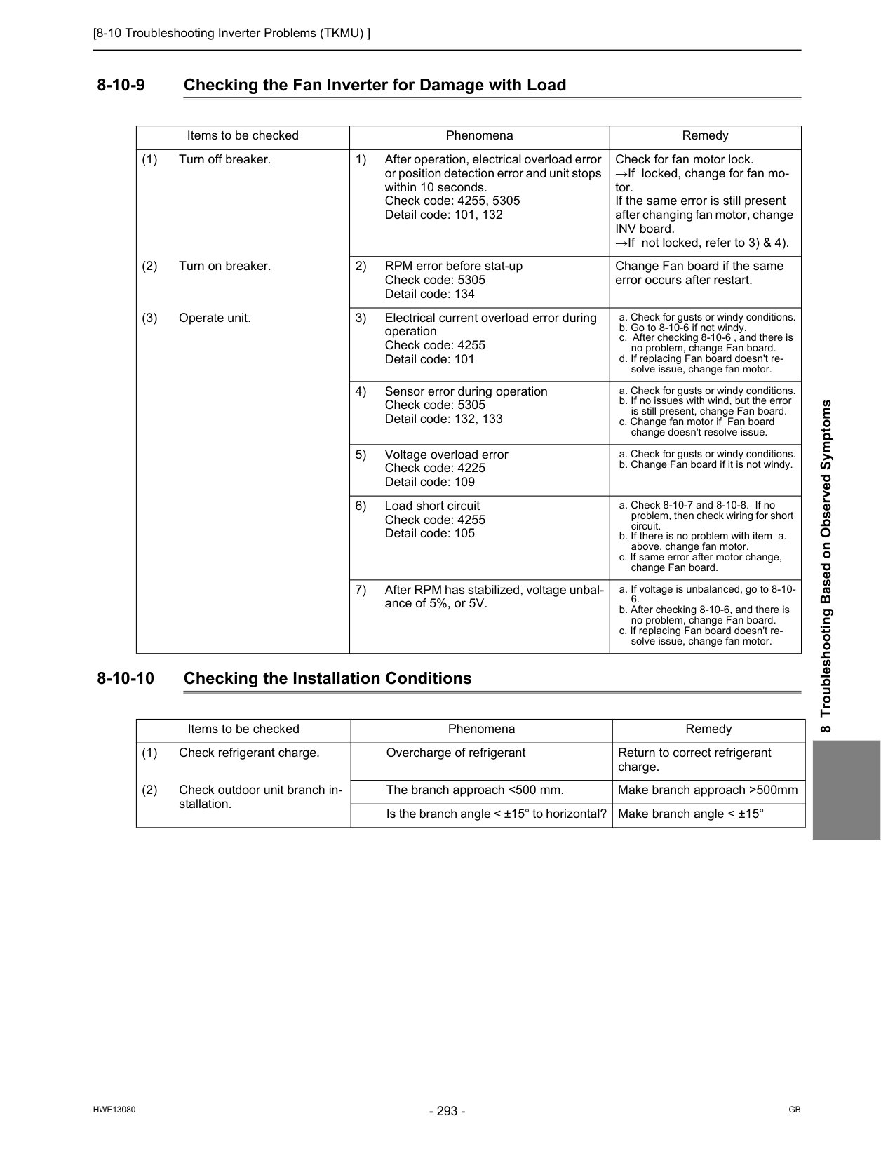
[8-10 Troubleshooting Inverter Problems (TKMU) ]
Hwe13080
Gb
8 Troubleshooting Based on Observed Symptoms 8-10-9 Checking the Fan Inverter for Damage with Load 8-10-10 Checking the Installation Conditions Items to be checked Phenomena Remedy (1) Turn off breaker. 1) After operation, electrical overload error or position detection error and unit stops within 10 seconds. Check code: 4255, 5305 Detail code: 101, 132 Check for fan motor lock. →If locked, change for fan mo- tor. If the same error is still present after changing fan motor, change INV board. →If not locked, refer to 3) & 4). (2) Turn on breaker. 2) RPM error before stat-up Check code: 5305 Detail code: 134 Change Fan board if the same error occurs after restart. (3) Operate unit. 3) Electrical current overload error during operation Check code: 4255 Detail code: 101 a. Check for gusts or windy conditions. b. Go to 8-10-6 if not windy. c. After checking 8-10-6 , and there is no problem, change Fan board. d. If replacing Fan board doesn't re- solve issue, change fan motor. 4) Sensor error during operation Check code: 5305 Detail code: 132, 133 a. Check for gusts or windy conditions. b. If no issues with wind, but the error is still present, change Fan board. c. Change fan motor if Fan board change doesn't resolve issue. 5) Voltage overload error Check code: 4225 Detail code: 109 a. Check for gusts or windy conditions. b. Change Fan board if it is not windy. 6) Load short circuit Check code: 4255 Detail code: 105 a. Check 8-10-7 and 8-10-8. If no problem, then check wiring for short circuit. b. If there is no problem with item a. above, change fan motor. c. If same error after motor change, change Fan board. 7) After RPM has stabilized, voltage unbal- ance of 5%, or 5V. a. If voltage is unbalanced, go to 8-10-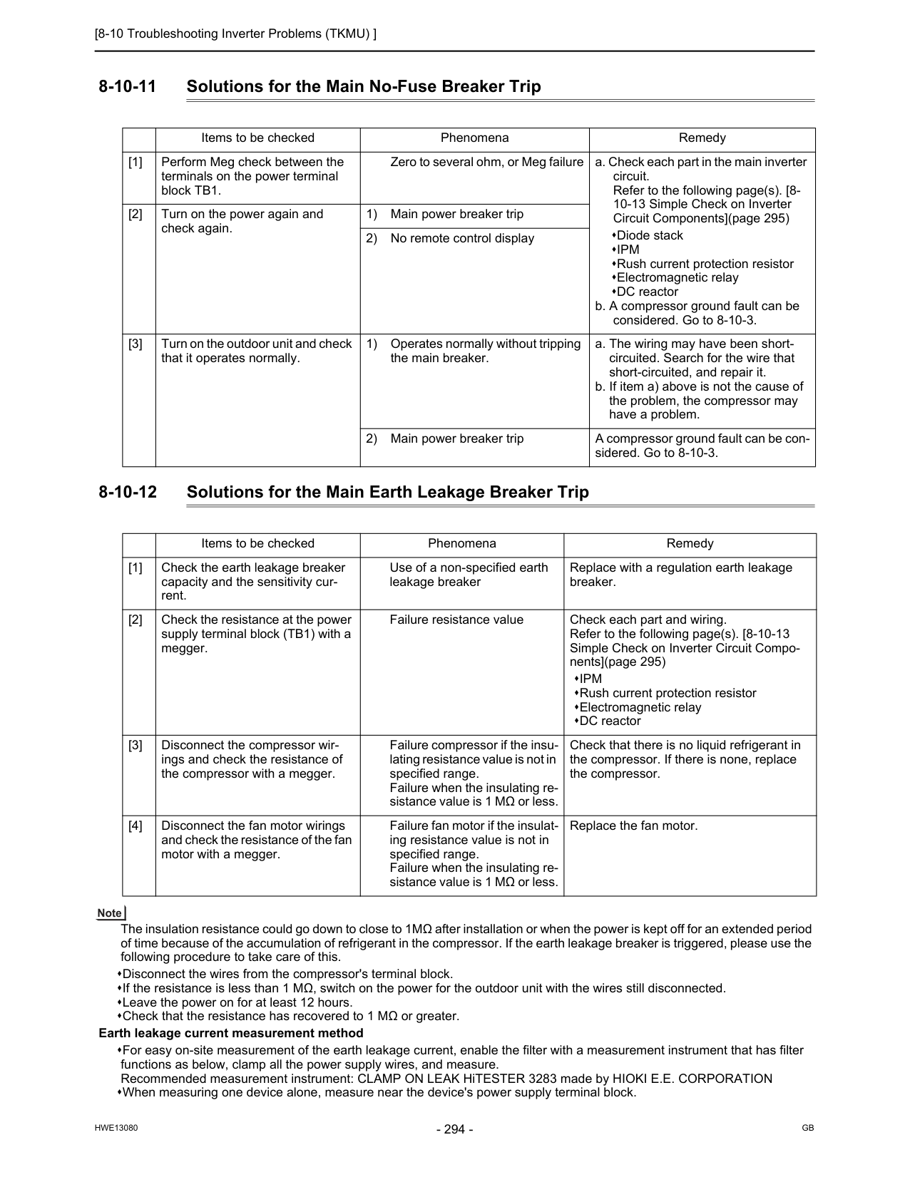
[8-10 Troubleshooting Inverter Problems (TKMU) ]
Hwe13080
Gb
8-10-11 Solutions for the Main No-Fuse Breaker Trip 8-10-12 Solutions for the Main Earth Leakage Breaker Trip The insulation resistance could go down to close to 1MΩ after installation or when the power is kept off for an extended period of time because of the accumulation of refrigerant in the compressor. If the earth leakage breaker is triggered, please use the following procedure to take care of this. Disconnect the wires from the compressor's terminal block. If the resistance is less than 1 MΩ, switch on the power for the outdoor unit with the wires still disconnected. Leave the power on for at least 12 hours. Check that the resistance has recovered to 1 MΩ or greater. Earth leakage current measurement method For easy on-site measurement of the earth leakage current, enable the filter with a measurement instrument that has filter functions as below, clamp all the power supply wires, and measure. Recommended measurement instrument: CLAMP ON LEAK HiTESTER 3283 made by HIOKI E.E. CORPORATION When measuring one device alone, measure near the device's power supply terminal block. Items to be checked Phenomena Remedy [1] Perform Meg check between the terminals on the power terminal block TB1. Zero to several ohm, or Meg failure a. Check each part in the main inverter circuit. Refer to the following page(s). [8- 10-13 Simple Check on Inverter Circuit Components](page 295) Diode stackIpm
Rush current protection resistor Electromagnetic relay DC reactor b. A compressor ground fault can be considered. Go to 8-10-3. [2] Turn on the power again and check again. 1) Main power breaker trip 2) No remote control display [3] Turn on the outdoor unit and check that it operates normally. 1) Operates normally without tripping the main breaker. a. The wiring may have been short- circuited. Search for the wire that short-circuited, and repair it. b. If item a) above is not the cause of the problem, the compressor may have a problem. 2) Main power breaker trip A compressor ground fault can be con- sidered. Go to 8-10-3. Items to be checked Phenomena Remedy [1] Check the earth leakage breaker capacity and the sensitivity cur- rent. Use of a non-specified earth leakage breaker Replace with a regulation earth leakage breaker. [2] Check the resistance at the power supply terminal block (TB1) with a megger. Failure resistance value Check each part and wiring. Refer to the following page(s). [8-10-13 Simple Check on Inverter Circuit Compo- nents](page 295)Ipm
Rush current protection resistor Electromagnetic relay DC reactor [3] Disconnect the compressor wir- ings and check the resistance of the compressor with a megger. Failure compressor if the insu- lating resistance value is not in specified range. Failure when the insulating re- sistance value is 1 MΩ or less. Check that there is no liquid refrigerant in the compressor. If there is none, replace the compressor. [4] Disconnect the fan motor wirings and check the resistance of the fan motor with a megger. Failure fan motor if the insulat- ing resistance value is not in specified range. Failure when the insulating re- sistance value is 1 MΩ or less. Replace the fan motor.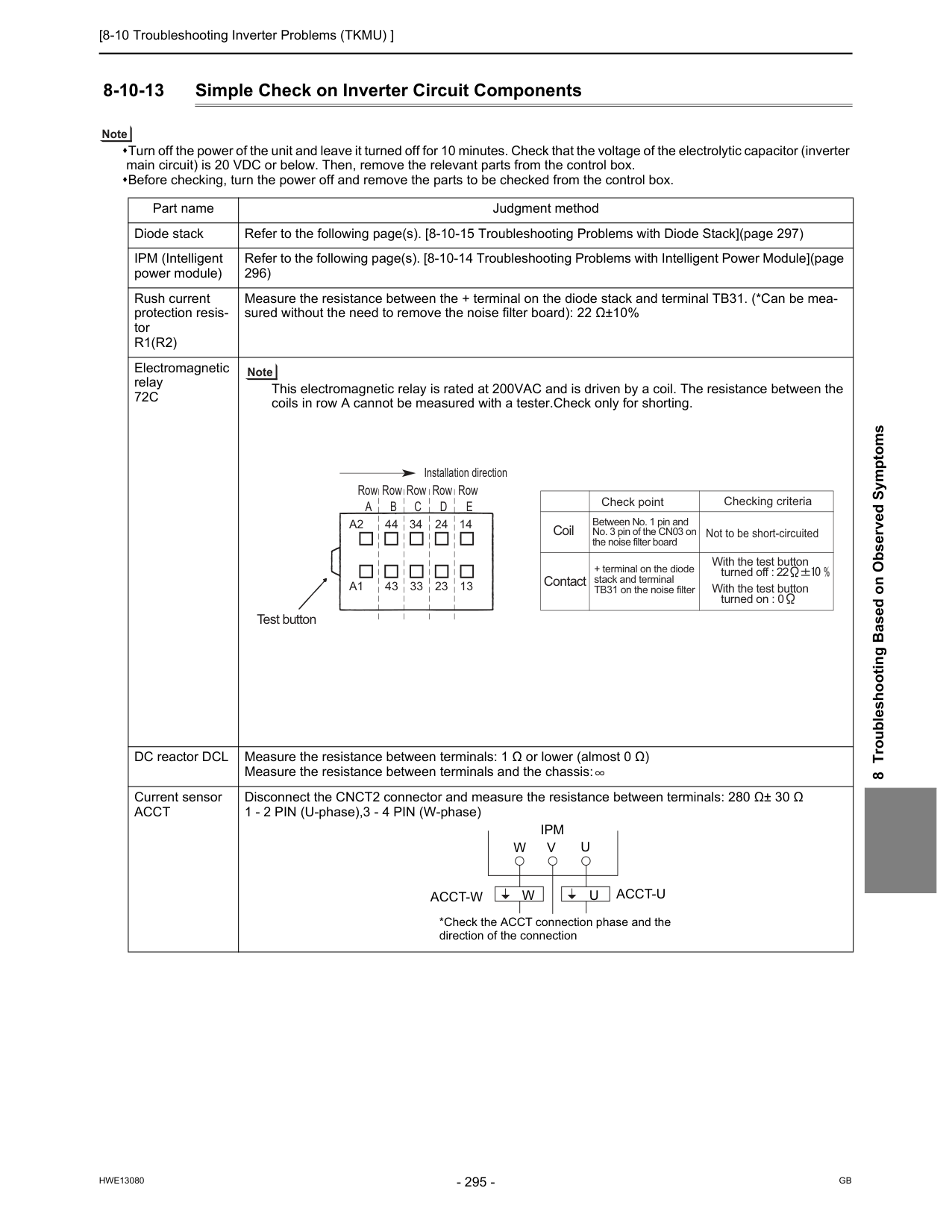
[8-10 Troubleshooting Inverter Problems (TKMU) ]
Hwe13080
Gb
8 Troubleshooting Based on Observed Symptoms 8-10-13 Simple Check on Inverter Circuit Components Turn off the power of the unit and leave it turned off for 10 minutes. Check that the voltage of the electrolytic capacitor (inverter main circuit) is 20 VDC or below. Then, remove the relevant parts from the control box. Before checking, turn the power off and remove the parts to be checked from the control box. Part name Judgment method Diode stack Refer to the following page(s). [8-10-15 Troubleshooting Problems with Diode Stack](page 297) IPM (Intelligent power module) Refer to the following page(s). [8-10-14 Troubleshooting Problems with Intelligent Power Module](page 296) Rush current protection resis- torR1(R2)
Measure the resistance between the + terminal on the diode stack and terminal TB31. (*Can be mea- sured without the need to remove the noise filter board): 22 Ω±10% Electromagnetic relay72C
This electromagnetic relay is rated at 200VAC and is driven by a coil. The resistance between the coils in row A cannot be measured with a tester.Check only for shorting. DC reactor DCL Measure the resistance between terminals: 1 Ω or lower (almost 0 Ω) Measure the resistance between terminals and the chassis: Current sensorAcct
Disconnect the CNCT2 connector and measure the resistance between terminals: 280 Ω± 30 Ω 1 - 2 PIN (U-phase),3 - 4 PIN (W-phase) Installation direction Test button RowA
RowB
RowC
RowD
RowE
A2
44 34 24 14 43 33 23 13A1
Check point Not to be short-circuited Coil Contact Checking criteria Between No. 1 pin and No. 3 pin of the CN03 on the noise filter board + terminal on the diode stack and terminal TB31 on the noise filter With the test button turned on : 0 With the test button turned off :U
U
V
Ipm
*Check the ACCT connection phase and the direction of the connectionW
Acct-W
W
Acct-U
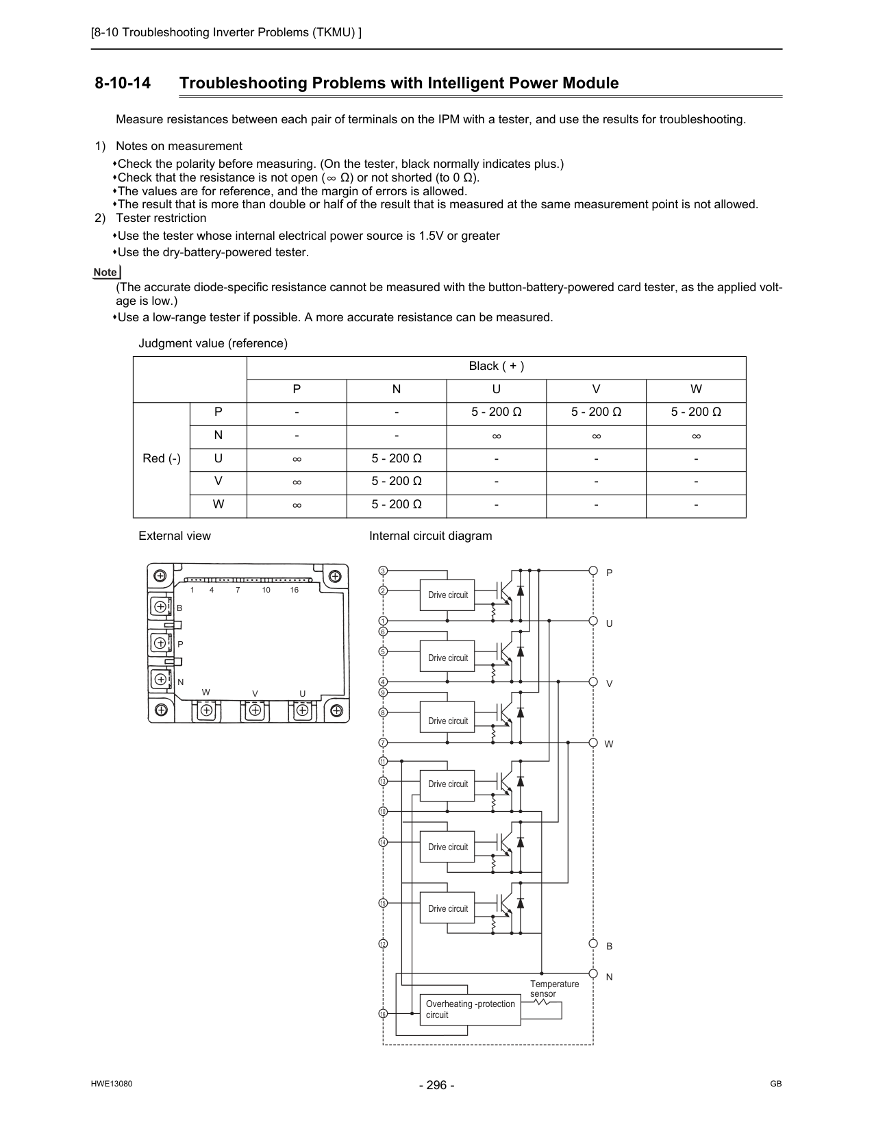
[8-10 Troubleshooting Inverter Problems (TKMU) ]
Hwe13080
Gb
8-10-14 Troubleshooting Problems with Intelligent Power Module Measure resistances between each pair of terminals on the IPM with a tester, and use the results for troubleshooting. 1) Notes on measurement Check the polarity before measuring. (On the tester, black normally indicates plus.) Check that the resistance is not open ( Ω) or not shorted (to 0 Ω). The values are for reference, and the margin of errors is allowed. The result that is more than double or half of the result that is measured at the same measurement point is not allowed. 2) Tester restriction Use the tester whose internal electrical power source is 1.5V or greater Use the dry-battery-powered tester. (The accurate diode-specific resistance cannot be measured with the button-battery-powered card tester, as the applied volt- age is low.) Use a low-range tester if possible. A more accurate resistance can be measured. Judgment value (reference) Black ( + )P
N
U
V
W
Red (-)P
5 - 200 Ω
5 - 200 Ω
5 - 200 Ω
N
U
5 - 200 Ω
V
5 - 200 Ω
W
5 - 200 Ω
W
V
U
B
P
N
V
U
P
W
N
B
3 2 1 6 5 4 9 8 7 11 13 10 14 15 12 16 Drive circuit Drive circuit Drive circuit Drive circuit Drive circuit Drive circuit Overheating -protection circuit Temperature sensor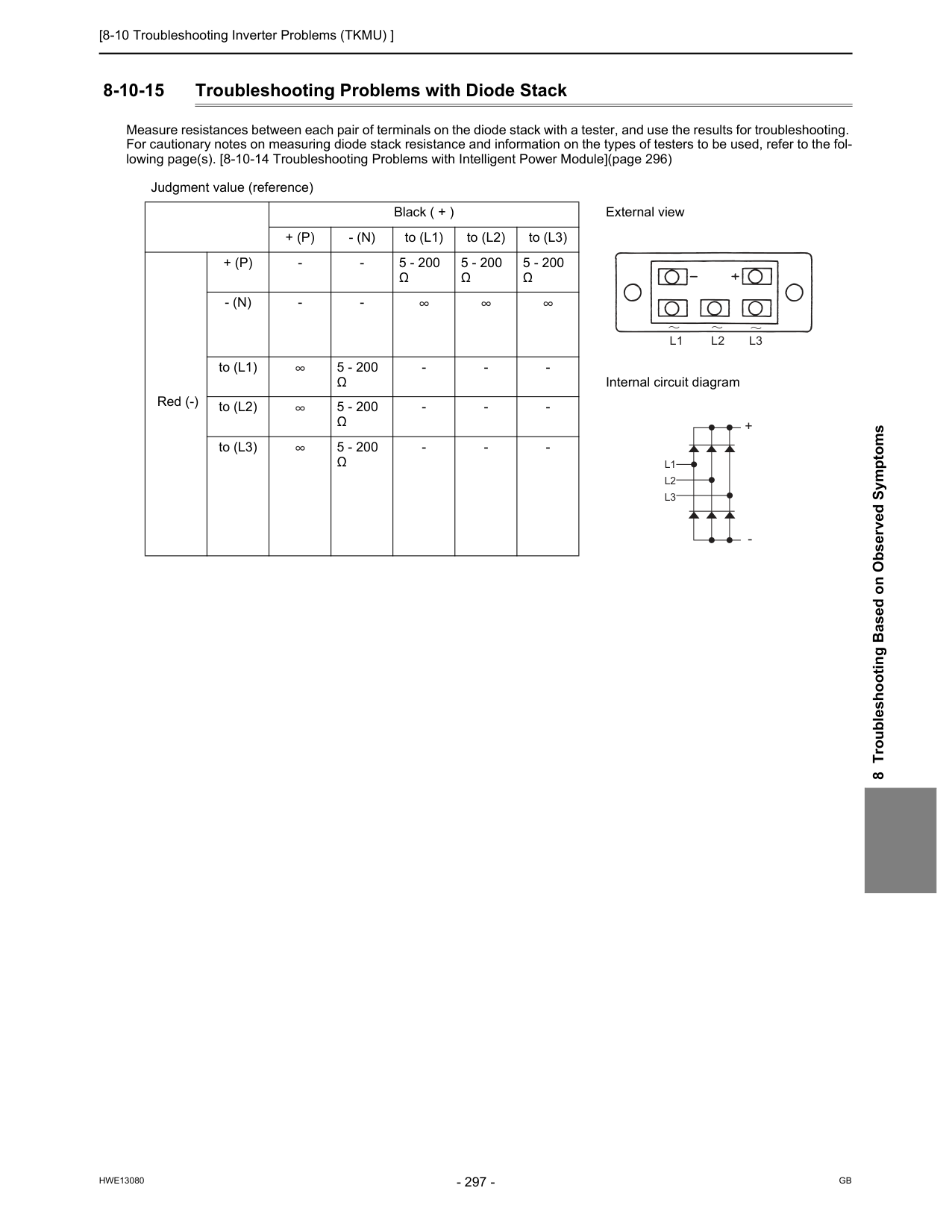
[8-10 Troubleshooting Inverter Problems (TKMU) ]
Hwe13080
Gb
8 Troubleshooting Based on Observed Symptoms 8-10-15 Troubleshooting Problems with Diode Stack Measure resistances between each pair of terminals on the diode stack with a tester, and use the results for troubleshooting. For cautionary notes on measuring diode stack resistance and information on the types of testers to be used, refer to the fol- lowing page(s). [8-10-14 Troubleshooting Problems with Intelligent Power Module](page 296) Judgment value (reference) Black ( + ) External view+ (P)
- (N)
to (L1) to (L2) to (L3) Red (-)+ (P)
Ω
5 - 200Ω
5 - 200Ω
- (N)
Ω
Ω
Ω
L1 L2 L3
L1
L2
L3
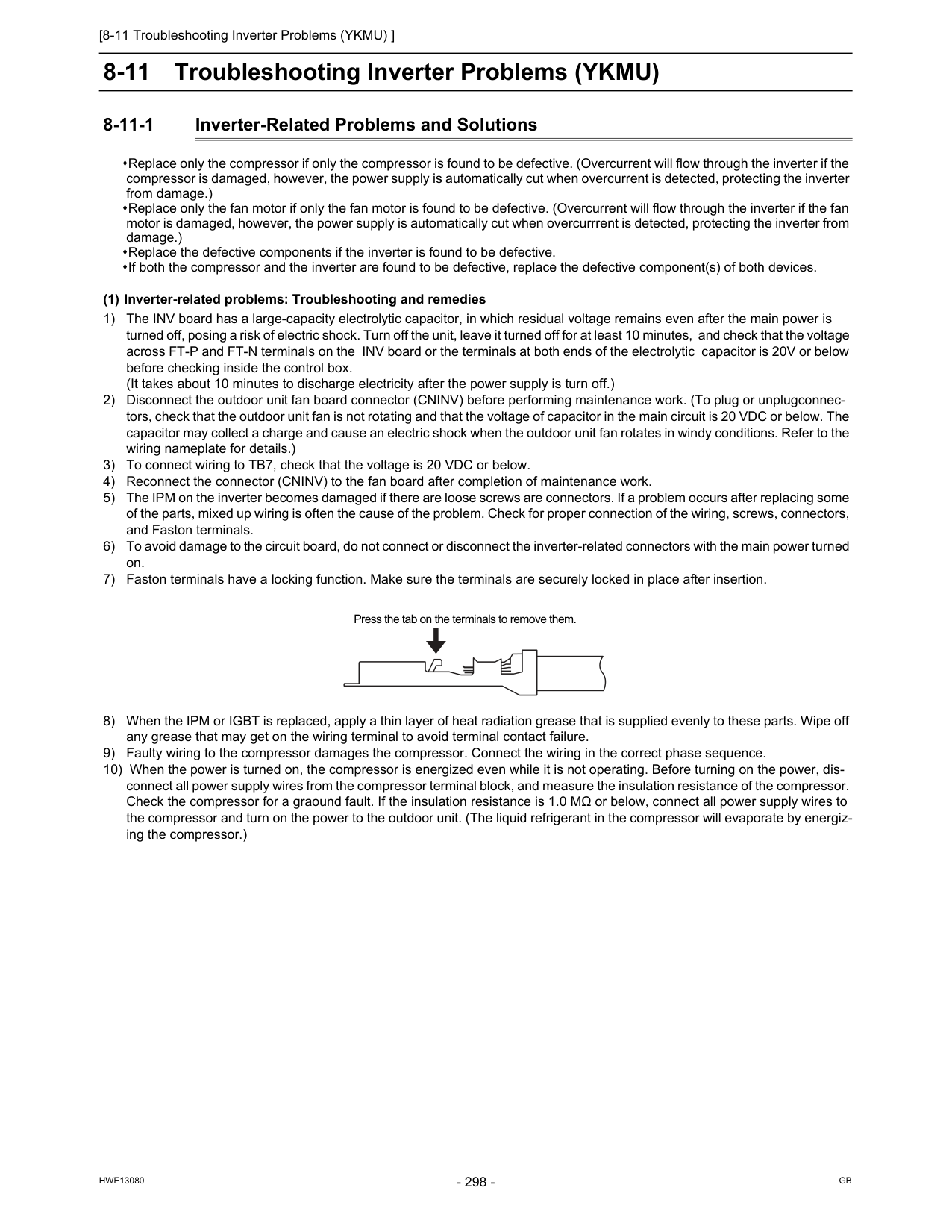
[8-11 Troubleshooting Inverter Problems (YKMU) ]
Hwe13080
Gb
8-11 Troubleshooting Inverter Problems (YKMU) 8-11-1 Inverter-Related Problems and Solutions Replace only the compressor if only the compressor is found to be defective. (Overcurrent will flow through the inverter if the compressor is damaged, however, the power supply is automatically cut when overcurrent is detected, protecting the inverter from damage.) Replace only the fan motor if only the fan motor is found to be defective. (Overcurrent will flow through the inverter if the fan motor is damaged, however, the power supply is automatically cut when overcurrrent is detected, protecting the inverter from damage.) Replace the defective components if the inverter is found to be defective. If both the compressor and the inverter are found to be defective, replace the defective component(s) of both devices. (1) Inverter-related problems: Troubleshooting and remedies 1) The INV board has a large-capacity electrolytic capacitor, in which residual voltage remains even after the main power is turned off, posing a risk of electric shock. Turn off the unit, leave it turned off for at least 10 minutes, and check that the voltage across FT-P and FT-N terminals on the INV board or the terminals at both ends of the electrolytic capacitor is 20V or below before checking inside the control box. (It takes about 10 minutes to discharge electricity after the power supply is turn off.) 2) Disconnect the outdoor unit fan board connector (CNINV) before performing maintenance work. (To plug or unplugconnec- tors, check that the outdoor unit fan is not rotating and that the voltage of capacitor in the main circuit is 20 VDC or below. The capacitor may collect a charge and cause an electric shock when the outdoor unit fan rotates in windy conditions. Refer to the wiring nameplate for details.) 3) To connect wiring to TB7, check that the voltage is 20 VDC or below. 4) Reconnect the connector (CNINV) to the fan board after completion of maintenance work. 5) The IPM on the inverter becomes damaged if there are loose screws are connectors. If a problem occurs after replacing some of the parts, mixed up wiring is often the cause of the problem. Check for proper connection of the wiring, screws, connectors, and Faston terminals. 6) To avoid damage to the circuit board, do not connect or disconnect the inverter-related connectors with the main power turned on. 7) Faston terminals have a locking function. Make sure the terminals are securely locked in place after insertion. 8) When the IPM or IGBT is replaced, apply a thin layer of heat radiation grease that is supplied evenly to these parts. Wipe off any grease that may get on the wiring terminal to avoid terminal contact failure. 9) Faulty wiring to the compressor damages the compressor. Connect the wiring in the correct phase sequence. 10) When the power is turned on, the compressor is energized even while it is not operating. Before turning on the power, dis- connect all power supply wires from the compressor terminal block, and measure the insulation resistance of the compressor. Check the compressor for a graound fault. If the insulation resistance is 1.0 MΩ or below, connect all power supply wires to the compressor and turn on the power to the outdoor unit. (The liquid refrigerant in the compressor will evaporate by energiz- ing the compressor.) Press the tab on the terminals to remove them.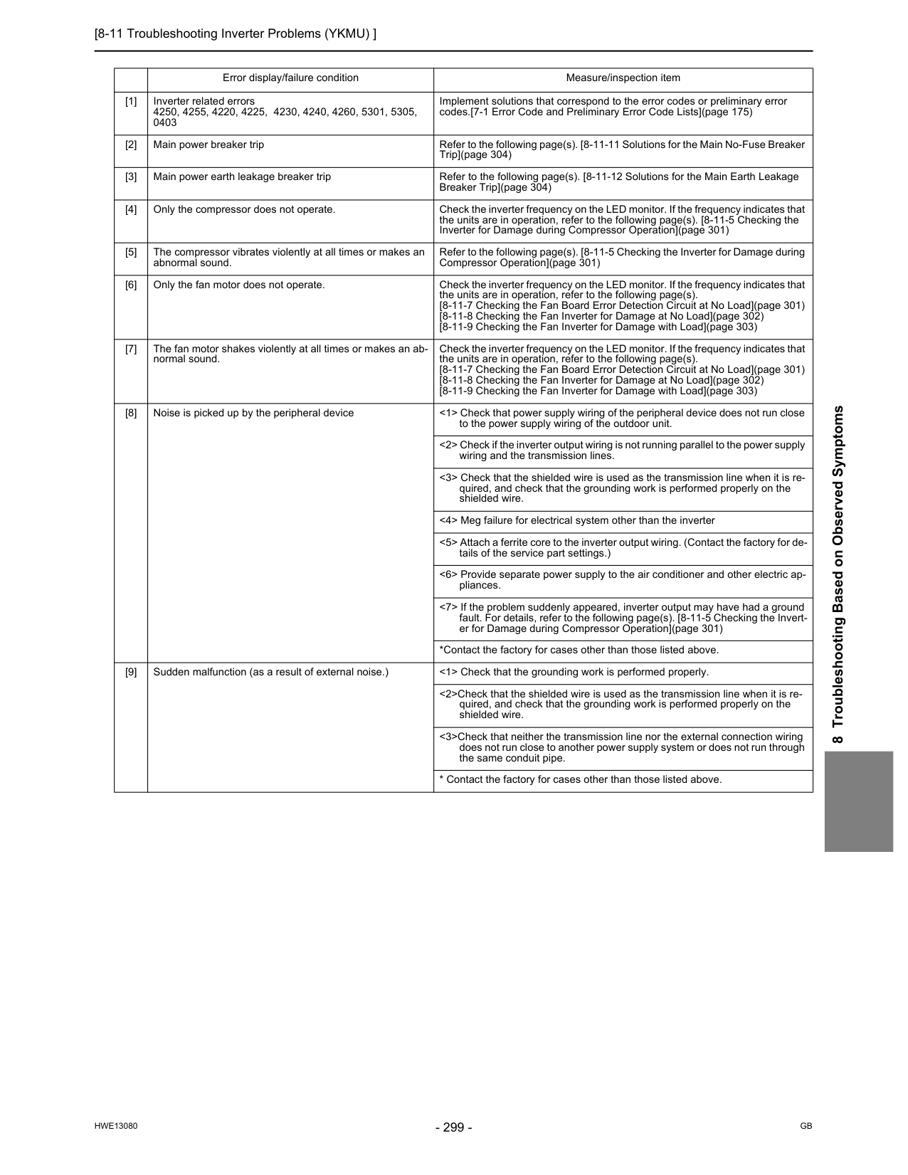
[8-11 Troubleshooting Inverter Problems (YKMU) ]
Hwe13080
Gb
8 Troubleshooting Based on Observed Symptoms Error display/failure condition Measure/inspection item [1] Inverter related errors 4250, 4255, 4220, 4225, 4230, 4240, 4260, 5301, 5305, 0403 Implement solutions that correspond to the error codes or preliminary error codes.[7-1 Error Code and Preliminary Error Code Lists](page 175) [2] Main power breaker trip Refer to the following page(s). [8-11-11 Solutions for the Main No-Fuse Breaker Trip](page 304) [3] Main power earth leakage breaker trip Refer to the following page(s). [8-11-12 Solutions for the Main Earth Leakage Breaker Trip](page 304) [4] Only the compressor does not operate. Check the inverter frequency on the LED monitor. If the frequency indicates that the units are in operation, refer to the following page(s). [8-11-5 Checking the Inverter for Damage during Compressor Operation](page 301) [5] The compressor vibrates violently at all times or makes an abnormal sound. Refer to the following page(s). [8-11-5 Checking the Inverter for Damage during Compressor Operation](page 301) [6] Only the fan motor does not operate. Check the inverter frequency on the LED monitor. If the frequency indicates that the units are in operation, refer to the following page(s). [8-11-7 Checking the Fan Board Error Detection Circuit at No Load](page 301) [8-11-8 Checking the Fan Inverter for Damage at No Load](page 302) [8-11-9 Checking the Fan Inverter for Damage with Load](page 303) [7] The fan motor shakes violently at all times or makes an ab- normal sound. Check the inverter frequency on the LED monitor. If the frequency indicates that the units are in operation, refer to the following page(s). [8-11-7 Checking the Fan Board Error Detection Circuit at No Load](page 301) [8-11-8 Checking the Fan Inverter for Damage at No Load](page 302) [8-11-9 Checking the Fan Inverter for Damage with Load](page 303) [8] Noise is picked up by the peripheral device <1> Check that power supply wiring of the peripheral device does not run close to the power supply wiring of the outdoor unit. <2> Check if the inverter output wiring is not running parallel to the power supply wiring and the transmission lines. <3> Check that the shielded wire is used as the transmission line when it is re- quired, and check that the grounding work is performed properly on the shielded wire. <4> Meg failure for electrical system other than the inverter <5> Attach a ferrite core to the inverter output wiring. (Contact the factory for de- tails of the service part settings.) <6> Provide separate power supply to the air conditioner and other electric ap- pliances. <7> If the problem suddenly appeared, inverter output may have had a ground fault. For details, refer to the following page(s). [8-11-5 Checking the Invert- er for Damage during Compressor Operation](page 301) *Contact the factory for cases other than those listed above. [9] Sudden malfunction (as a result of external noise.) <1> Check that the grounding work is performed properly. <2>Check that the shielded wire is used as the transmission line when it is re- quired, and check that the grounding work is performed properly on the shielded wire. <3>Check that neither the transmission line nor the external connection wiring does not run close to another power supply system or does not run through the same conduit pipe.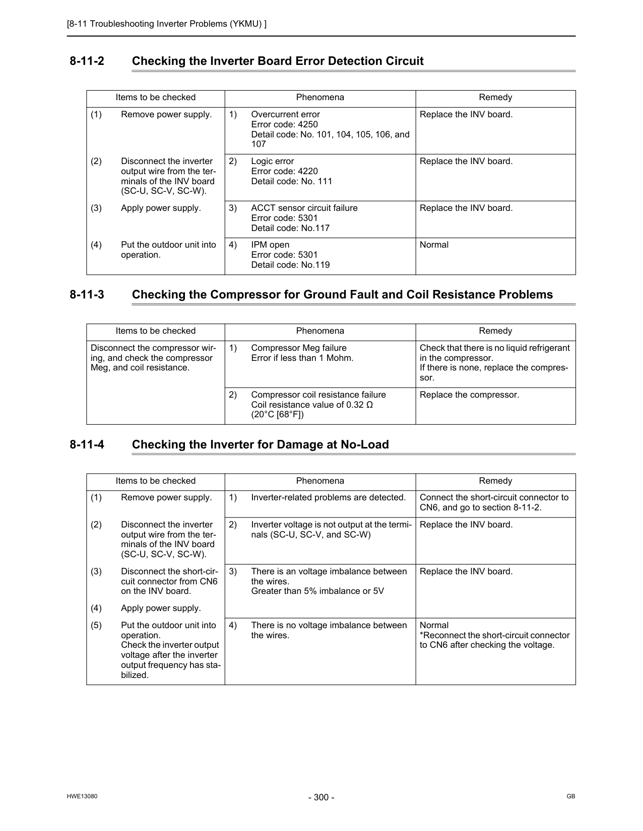
[8-11 Troubleshooting Inverter Problems (YKMU) ]
Hwe13080
Gb
8-11-2 Checking the Inverter Board Error Detection Circuit 8-11-3 Checking the Compressor for Ground Fault and Coil Resistance Problems 8-11-4 Checking the Inverter for Damage at No-Load Items to be checked Phenomena Remedy (1) Remove power supply. 1) Overcurrent error Error code: 4250 Detail code: No. 101, 104, 105, 106, and 107 Replace the INV board. (2) Disconnect the inverter output wire from the ter- minals of the INV board(Sc-U, Sc-V, Sc-W).
2) Logic error Error code: 4220 Detail code: No. 111 Replace the INV board. (3) Apply power supply. 3) ACCT sensor circuit failure Error code: 5301 Detail code: No.117 Replace the INV board. (4) Put the outdoor unit into operation. 4) IPM open Error code: 5301 Detail code: No.119 Normal Items to be checked Phenomena Remedy Disconnect the compressor wir- ing, and check the compressor Meg, and coil resistance. 1) Compressor Meg failure Error if less than 1 Mohm. Check that there is no liquid refrigerant in the compressor. If there is none, replace the compres- sor. 2) Compressor coil resistance failure Coil resistance value of 0.32 Ω(20°C [68°F])
Replace the compressor. Items to be checked Phenomena Remedy (1) Remove power supply. 1) Inverter-related problems are detected. Connect the short-circuit connector to CN6, and go to section 8-11-2. (2) Disconnect the inverter output wire from the ter- minals of the INV board(Sc-U, Sc-V, Sc-W).
2) Inverter voltage is not output at the termi- nals (SC-U, SC-V, and SC-W) Replace the INV board. (3) Disconnect the short-cir- cuit connector from CN6 on the INV board. 3) There is an voltage imbalance between the wires. Greater than 5% imbalance or 5V Replace the INV board. (4) Apply power supply. (5) Put the outdoor unit into operation. Check the inverter output voltage after the inverter output frequency has sta- bilized. 4) There is no voltage imbalance between the wires. Normal *Reconnect the short-circuit connector to CN6 after checking the voltage.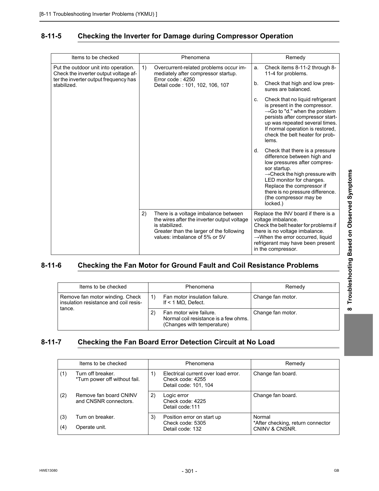
[8-11 Troubleshooting Inverter Problems (YKMU) ]
Hwe13080
Gb
8 Troubleshooting Based on Observed Symptoms 8-11-5 Checking the Inverter for Damage during Compressor Operation 8-11-6 Checking the Fan Motor for Ground Fault and Coil Resistance Problems 8-11-7 Checking the Fan Board Error Detection Circuit at No Load Items to be checked Phenomena Remedy Put the outdoor unit into operation. Check the inverter output voltage af- ter the inverter output frequency has stabilized. 1) Overcurrent-related problems occur im- mediately after compressor startup. Error code : 4250 Detail code : 101, 102, 106, 107 a. Check items 8-11-2 through 8- 11-4 for problems. b. Check that high and low pres- sures are balanced. c. Check that no liquid refrigerant is present in the compressor. →Go to "d." when the problem persists after compressor start- up was repeated several times. If normal operation is restored, check the belt heater for prob- lems. d. Check that there is a pressure difference between high and low pressures after compres- sor startup. →Check the high pressure with LED monitor for changes. Replace the compressor if there is no pressure difference. (the compressor may be locked.) 2) There is a voltage imbalance between the wires after the inverter output voltage is stabilized. Greater than the larger of the following values: imbalance of 5% or 5V Replace the INV board if there is a voltage imbalance. Check the belt heater for problems if there is no voltage imbalance. →When the error occurred, liquid refrigerant may have been present in the compressor. Items to be checked Phenomena Remedy Remove fan motor winding. Check insulation resistance and coil resis- tance. 1) Fan motor insulation failure. If < 1 MΩ, Defect. Change fan motor. 2) Fan motor wire failure. Normal coil resistance is a few ohms. (Changes with temperature) Change fan motor. Items to be checked Phenomena Remedy (1) Turn off breaker. *Turn power off without fail. 1) Electrical current over load error. Check code: 4255 Detail code: 101, 104 Change fan board. (2) Remove fan board CNINV and CNSNR connectors. 2) Logic error Check code: 4225 Detail code:111 Change fan board. (3) Turn on breaker. 3) Position error on start up Check code: 5305 Detail code: 132 Normal *After checking, return connectorCninv & Cnsnr.
(4) Operate unit.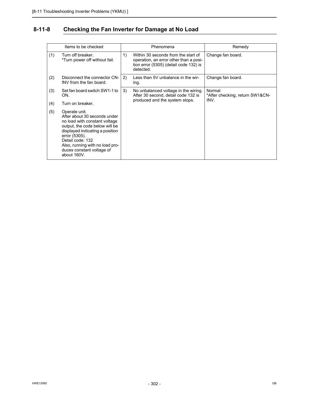
[8-11 Troubleshooting Inverter Problems (YKMU) ]
Hwe13080
Gb
8-11-8 Checking the Fan Inverter for Damage at No Load Items to be checked Phenomena Remedy (1) Turn off breaker. *Turn power off without fail. 1) Within 30 seconds from the start of operation, an error other than a posi- tion error (5305) (detail code 132) is detected. Change fan board. (2) Disconnect the connector CN- INV from the fan board. 2) Less than 5V unbalance in the wir- ing. Change fan board. (3) Set fan board switch SW1-1 toOn.
3) No unbalanced voltage in the wiring. After 30 second, detail code 132 is produced and the system stops. Normal *After checking, return SW1&CN-Inv.
(4) Turn on breaker. (5) Operate unit. After about 30 seconds under no load with constant voltage output, the code below will be displayed indicating a position error (5305). Detail code: 132 Also, running with no load pro- duces constant voltage of about 160V.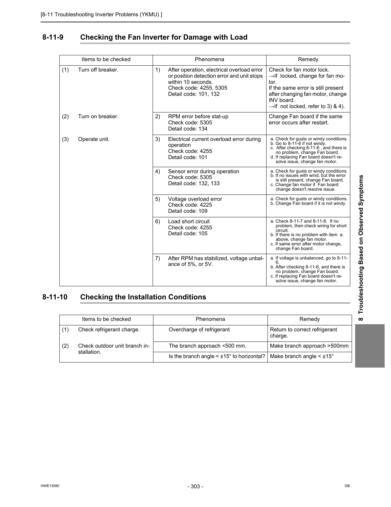
[8-11 Troubleshooting Inverter Problems (YKMU) ]
Hwe13080
Gb
8 Troubleshooting Based on Observed Symptoms 8-11-9 Checking the Fan Inverter for Damage with Load 8-11-10 Checking the Installation Conditions Items to be checked Phenomena Remedy (1) Turn off breaker. 1) After operation, electrical overload error or position detection error and unit stops within 10 seconds. Check code: 4255, 5305 Detail code: 101, 132 Check for fan motor lock. →If locked, change for fan mo- tor. If the same error is still present after changing fan motor, change INV board. →If not locked, refer to 3) & 4). (2) Turn on breaker. 2) RPM error before stat-up Check code: 5305 Detail code: 134 Change Fan board if the same error occurs after restart. (3) Operate unit. 3) Electrical current overload error during operation Check code: 4255 Detail code: 101 a. Check for gusts or windy conditions. b. Go to 8-11-6 if not windy. c. After checking 8-11-6 , and there is no problem, change Fan board. d. If replacing Fan board doesn't re- solve issue, change fan motor. 4) Sensor error during operation Check code: 5305 Detail code: 132, 133 a. Check for gusts or windy conditions. b. If no issues with wind, but the error is still present, change Fan board. c. Change fan motor if Fan board change doesn't resolve issue. 5) Voltage overload error Check code: 4225 Detail code: 109 a. Check for gusts or windy conditions. b. Change Fan board if it is not windy. 6) Load short circuit Check code: 4255 Detail code: 105 a. Check 8-11-7 and 8-11-8. If no problem, then check wiring for short circuit. b. If there is no problem with item a. above, change fan motor. c. If same error after motor change, change Fan board. 7) After RPM has stabilized, voltage unbal- ance of 5%, or 5V. a. If voltage is unbalanced, go to 8-11-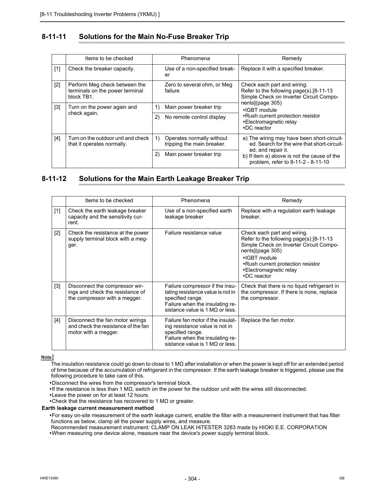
[8-11 Troubleshooting Inverter Problems (YKMU) ]
Hwe13080
Gb
8-11-11 Solutions for the Main No-Fuse Breaker Trip 8-11-12 Solutions for the Main Earth Leakage Breaker Trip The insulation resistance could go down to close to 1 MΩ after installation or when the power is kept off for an extended period of time because of the accumulation of refrigerant in the compressor. If the earth leakage breaker is triggered, please use the following procedure to take care of this. Disconnect the wires from the compressor's terminal block. If the resistance is less than 1 MΩ, switch on the power for the outdoor unit with the wires still disconnected. Leave the power on for at least 12 hours. Check that the resistance has recovered to 1 MΩ or greater. Earth leakage current measurement method For easy on-site measurement of the earth leakage current, enable the filter with a measurement instrument that has filter functions as below, clamp all the power supply wires, and measure. Recommended measurement instrument: CLAMP ON LEAK HiTESTER 3283 made by HIOKI E.E. CORPORATION When measuring one device alone, measure near the device's power supply terminal block. Items to be checked Phenomena Remedy [1] Check the breaker capacity. Use of a non-specified break- er Replace it with a specified breaker. [2] Perform Meg check between the terminals on the power terminal block TB1. Zero to several ohm, or Meg failure Check each part and wiring. Refer to the following page(s).[8-11-13 Simple Check on Inverter Circuit Compo- nents](page 305) IGBT module Rush current protection resistor Electromagnetic relay DC reactor [3] Turn on the power again and check again. 1) Main power breaker trip 2) No remote control display [4] Turn on the outdoor unit and check that it operates normally. 1) Operates normally without tripping the main breaker. a) The wiring may have been short-circuit- ed. Search for the wire that short-circuit- ed, and repair it. b) If item a) above is not the cause of the problem, refer to 8-11-2 - 8-11-10 2) Main power breaker trip Items to be checked Phenomena Remedy [1] Check the earth leakage breaker capacity and the sensitivity cur- rent. Use of a non-specified earth leakage breaker Replace with a regulation earth leakage breaker. [2] Check the resistance at the power supply terminal block with a meg- ger. Failure resistance value Check each part and wiring. Refer to the following page(s).[8-11-13 Simple Check on Inverter Circuit Compo- nents](page 305) IGBT module Rush current protection resistor Electromagnetic relay DC reactor [3] Disconnect the compressor wir- ings and check the resistance of the compressor with a megger. Failure compressor if the insu- lating resistance value is not in specified range. Failure when the insulating re- sistance value is 1 MΩ or less. Check that there is no liquid refrigerant in the compressor. If there is none, replace the compressor. [4] Disconnect the fan motor wirings and check the resistance of the fan motor with a megger. Failure fan motor if the insulat- ing resistance value is not in specified range. Failure when the insulating re- sistance value is 1 MΩ or less. Replace the fan motor.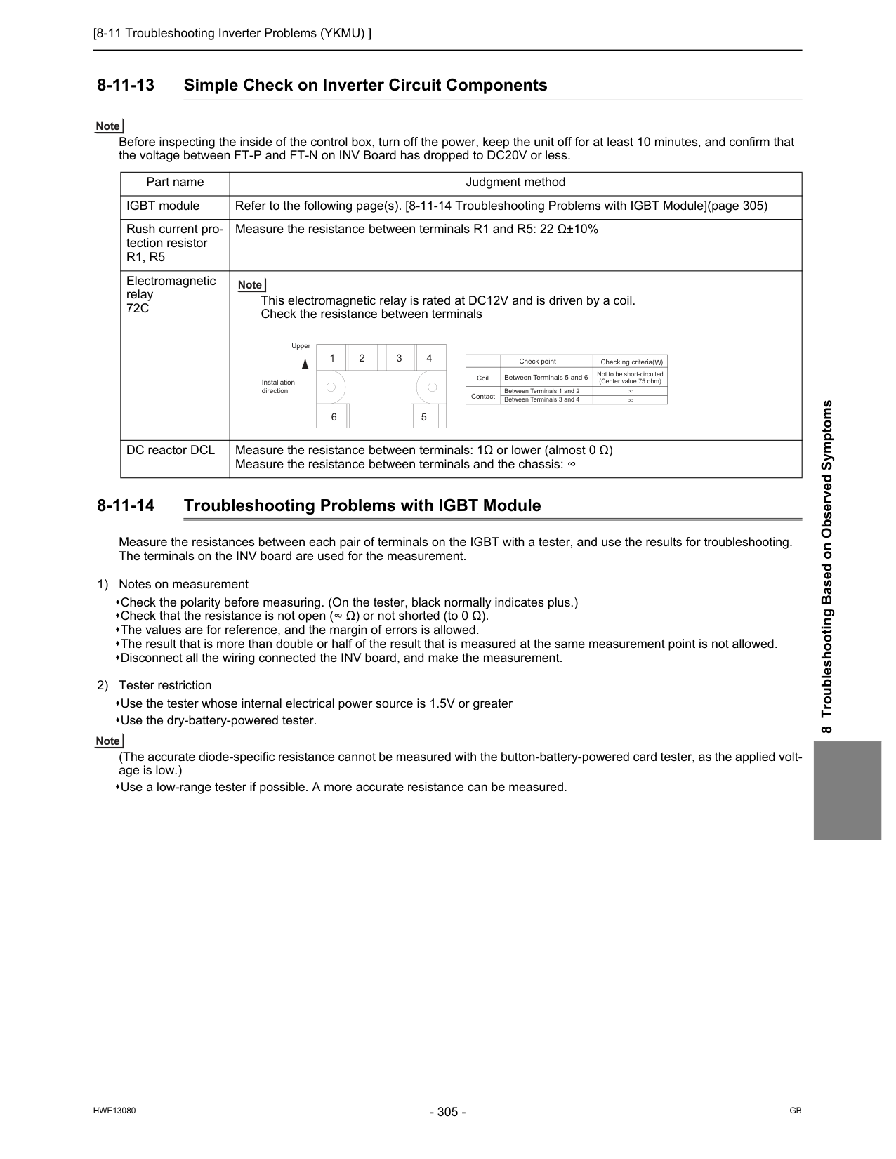
[8-11 Troubleshooting Inverter Problems (YKMU) ]
Hwe13080
Gb
8 Troubleshooting Based on Observed Symptoms 8-11-13 Simple Check on Inverter Circuit Components Before inspecting the inside of the control box, turn off the power, keep the unit off for at least 10 minutes, and confirm that the voltage between FT-P and FT-N on INV Board has dropped to DC20V or less. 8-11-14 Troubleshooting Problems with IGBT Module Measure the resistances between each pair of terminals on the IGBT with a tester, and use the results for troubleshooting. The terminals on the INV board are used for the measurement. 1) Notes on measurement Check the polarity before measuring. (On the tester, black normally indicates plus.) Check that the resistance is not open (∞ Ω) or not shorted (to 0 Ω). The values are for reference, and the margin of errors is allowed. The result that is more than double or half of the result that is measured at the same measurement point is not allowed. Disconnect all the wiring connected the INV board, and make the measurement. 2) Tester restriction Use the tester whose internal electrical power source is 1.5V or greater Use the dry-battery-powered tester. (The accurate diode-specific resistance cannot be measured with the button-battery-powered card tester, as the applied volt- age is low.) Use a low-range tester if possible. A more accurate resistance can be measured. Part name Judgment method IGBT module Refer to the following page(s). [8-11-14 Troubleshooting Problems with IGBT Module](page 305) Rush current pro- tection resistorR1, R5
Measure the resistance between terminals R1 and R5: 22 Ω±10% Electromagnetic relay72C
This electromagnetic relay is rated at DC12V and is driven by a coil. Check the resistance between terminals DC reactor DCL Measure the resistance between terminals: 1Ω or lower (almost 0 Ω) Measure the resistance between terminals and the chassis: ∞ 1 6 5 2 3 4 Upper Installation direction Check point Checking criteria( )W
Between Terminals 5 and 6 Between Terminals 1 and 2 Between Terminals 3 and 4 Not to be short-circuited (Center value 75 ohm) Coil Contact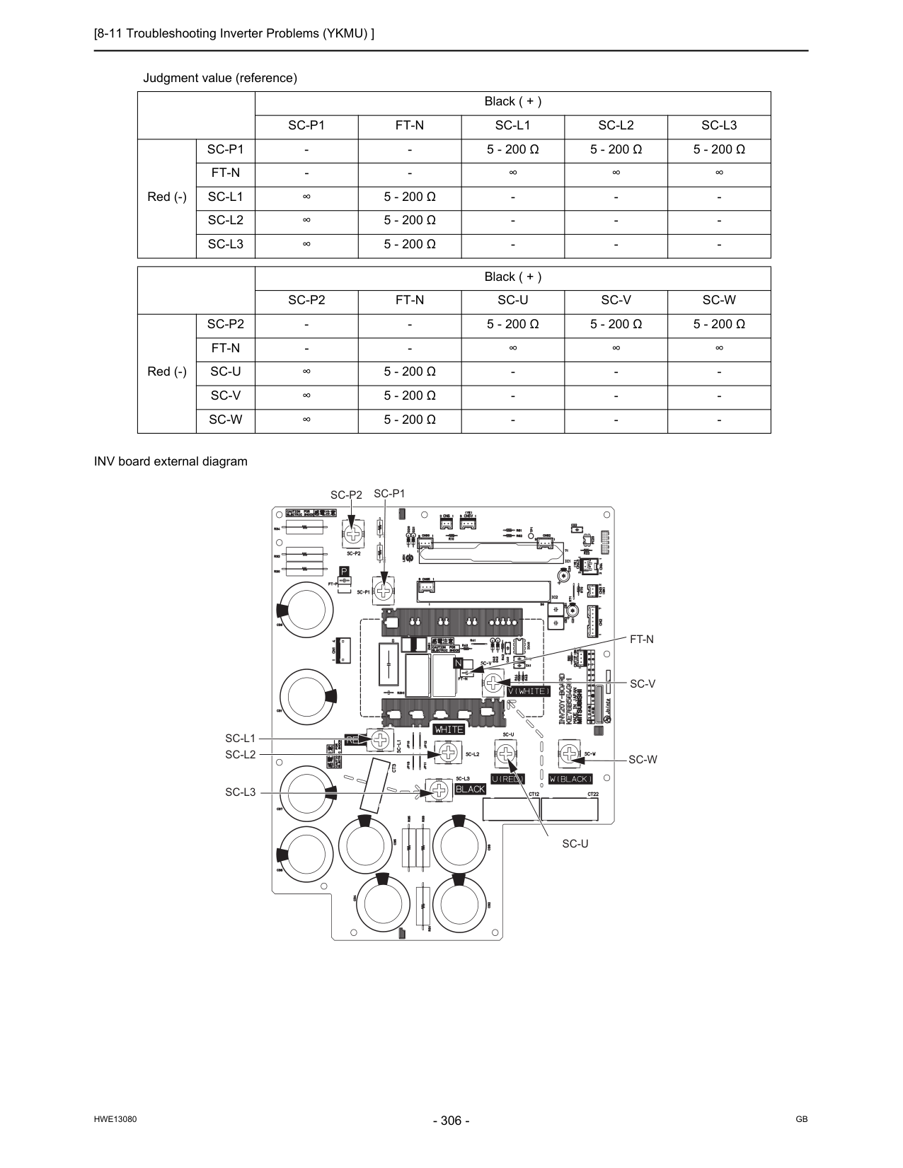
[8-11 Troubleshooting Inverter Problems (YKMU) ]
Hwe13080
Gb
INV board external diagram Judgment value (reference) Black ( + )Sc-P1
Ft-N
Sc-L1
Sc-L2
Sc-L3
Red (-)Sc-P1
5 - 200 Ω
5 - 200 Ω
5 - 200 Ω
Ft-N
Sc-L1
∞5 - 200 Ω
Sc-L2
5 - 200 Ω
Sc-L3
5 - 200 Ω
Sc-P2
Ft-N
Sc-U
Sc-V
Sc-W
Red (-)Sc-P2
5 - 200 Ω
5 - 200 Ω
5 - 200 Ω
Ft-N
Sc-U
∞5 - 200 Ω
Sc-V
5 - 200 Ω
Sc-W
5 - 200 Ω
Sc-U
Sc-W
Sc-V
Ft-N
Sc-P1
Sc-P2
Sc-L1
Sc-L2
Sc-L3
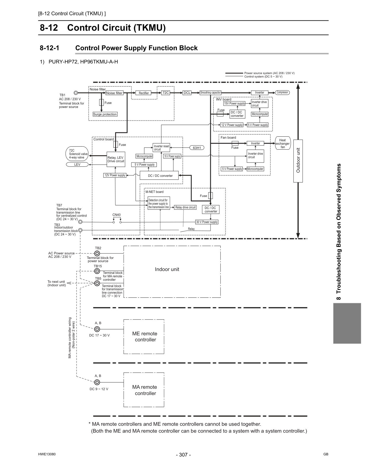
[8-12 Control Circuit (TKMU) ]
Hwe13080
Gb
8 Troubleshooting Based on Observed Symptoms 8-12 Control Circuit (TKMU) 8-12-1 Control Power Supply Function Block1) Pury-Hp72, Hp96Tkmu-A-H
Tb2
Tb15
Terminal block for power source
Tb5
Terminal block for MA remote controller Terminal block for transmission line connectionDc 17 ~ 30 V
Cn40
A, B
A, B
MA remote controller wiring (Non-polar 2 wire)Dc 17 ~ 30 V
Dc 9 ~ 12 V
ME remote controller MA remote controllerAc 208 / 230 V
Terminal block for power sourceTb1
Noise filter Noise filter Fuse Surge protection INV board
72C
Dcl
Rectifier Smoothing capacitor 15V Power supply Inverter drive circuit Microcomputer 5 V Power supply 12 V Power supplyDc / Dc
converter Fuse Inverter Compressor Heat exchanger fan Fuse Fan board Microcomputer 5 V Power supply Inverter Inverter drive circuit Outdoor unit Power source system (AC 208 / 230 V) Control system (DC 5 ~ 30 V)63H1
Inverter reset circuit DC / DC converter Microcomputer 5 V Power supply 16 V Power supply Fuse Detection circuit for the power supply to the transmission line M-NET boardDc / Dc
converter 30 V Power supply Relay drive circuit Relay Indoor unitLev
72C
Solenoid valve 4-way valve Fuse Control board 12V Power supply Relay, LEV Drive circuitAc 208 / 230 V
AC Power source To next unit (Indoor unit) Terminal block for transmission line for centralized control(Dc 24 ~ 30 V)
Tb7
Indoor/outdoor transmission block(Dc 24 ~ 30 V)
Tb3
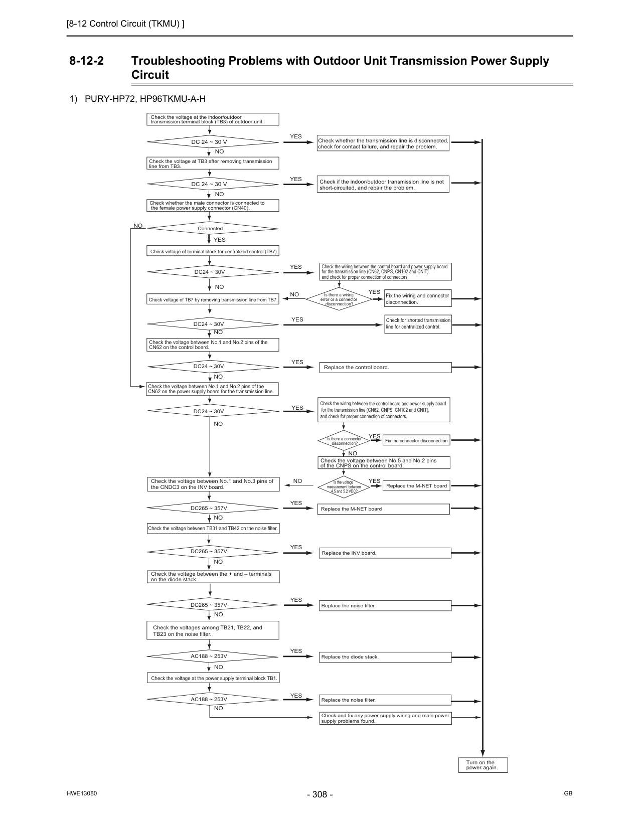
[8-12 Control Circuit (TKMU) ]
Hwe13080
Gb
8-12-2 Troubleshooting Problems with Outdoor Unit Transmission Power Supply Circuit1) Pury-Hp72, Hp96Tkmu-A-H
Dc24 ~ 30V
Yes
No
No
No
No
Check the voltage at the indoor/outdoor transmission terminal block (TB3) of outdoor unit.Dc 24 ~ 30 V
Dc 24 ~ 30 V
Check the voltage at TB3 after removing transmission line from TB3. Check whether the male connector is connected to the female power supply connector (CN40). Connected Check voltage of terminal block for centralized control (TB7).Yes
Yes
Yes
Check if the indoor/outdoor transmission line is not short-circuited, and repair the problem. Check whether the transmission line is disconnected, check for contact failure, and repair the problem. Check the voltage between No.1 and No.2 pins of the CN62 on the control board. Check the voltage between No.1 and No.2 pins of the CN62 on the power supply board for the transmission line.Dc24 ~ 30V
Dc24 ~ 30V
Dc24 ~ 30V
No
No
Check voltage of TB7 by removing transmission line from TB7.Yes
Yes
Yes
No
Check the wiring between the control board and power supply board for the transmission line (CN62, CNPS, CN102 and CNIT), and check for proper connection of connectors. Fix the wiring and connector disconnection. Check for shorted transmission line for centralized control.Yes
Is there a wiring error or a connector disconnection? Replace the control board. Check the wiring between the control board and power supply board for the transmission line (CN62, CNPS, CN102 and CNIT), and check for proper connection of connectors. Check the voltage between No.5 and No.2 pins of the CNPS on the control board. Is the voltage measurement between 4.5 and 5.2 VDC? Is there a connector disconnection? Fix the connector disconnection. Replace the M-NET board Replace the M-NET boardYes
Yes
Yes
Yes
Yes
Yes
Yes
No
No
Replace the INV board. Replace the noise filter. Replace the noise filter. Replace the diode stack. Check and fix any power supply wiring and main power supply problems found. Turn on the power again. Check the voltage between No.1 and No.3 pins of the CNDC3 on the INV board. Check the voltage between TB31 and TB42 on the noise filter. Check the voltage between the + and – terminals on the diode stack.Dc265 ~ 357V
Dc265 ~ 357V
Dc265 ~ 357V
No
No
No
Check the voltages among TB21, TB22, and TB23 on the noise filter. Check the voltage at the power supply terminal block TB1.Ac188 ~ 253V
Ac188 ~ 253V
No
No
No
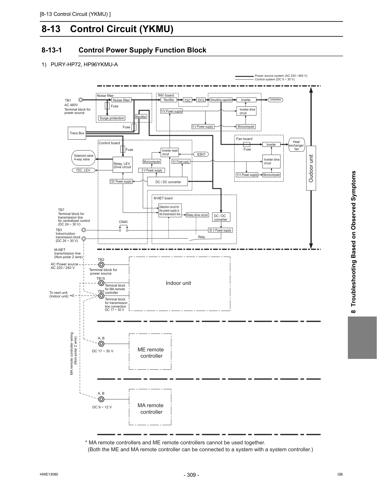
[8-13 Control Circuit (YKMU) ]
Hwe13080
Gb
8 Troubleshooting Based on Observed Symptoms 8-13 Control Circuit (YKMU) 8-13-1 Control Power Supply Function Block1) Pury-Hp72, Hp96Ykmu-A
Outdoor unit Power source system (AC 230 / 460 V) Control system (DC 5 ~ 30 V)A, B
A, B
M-Net
transmission line (Non-polar 2 wire)Ac 220 / 240 V
AC Power source To next unit (Indoor unit) MA remote controller wiring (Non-polar 2 wire)Dc 17 ~ 30 V
Dc 9 ~ 12 V
Tb2
Tb15
Terminal block for power source
Tb5
Terminal block for MA remote controller Terminal block for transmission line connectionDc 17 ~ 30 V
Ac 460V
Terminal block for power sourceTb1
Noise filter Noise filter Fuse Fuse Fuse
72C, Lev
Fuse Surge protection INV board Control board Fan board63H1
72C
Dcl
DC / DC converter Detection circuit for the power supply to the transmission line M-NET boardDc / Dc
converter Microcomputer Microcomputer Microcomputer 5 V Power supply 16 V Power supply 12V Power supply 30 V Power supply Relay drive circuit Relay 5 V Power supply 5 V Power supply 17V Power supply Smoothing capacitor Inverter Inverter Inverter drive circuit Inverter drive circuit Inverter reset circuit Rectifier Compressor Heat exchanger fan Relay, LEV Drive circuit Solenoid valve 4-way valveCn40
Terminal block for transmission line for centralized control(Dc 24 ~ 30 V)
Tb7
Indoor/outdoor transmission block(Dc 24 ~ 30 V)
Tb3
Rectifier Trans Box ME remote controller MA remote controller Indoor unit Oudoor unit
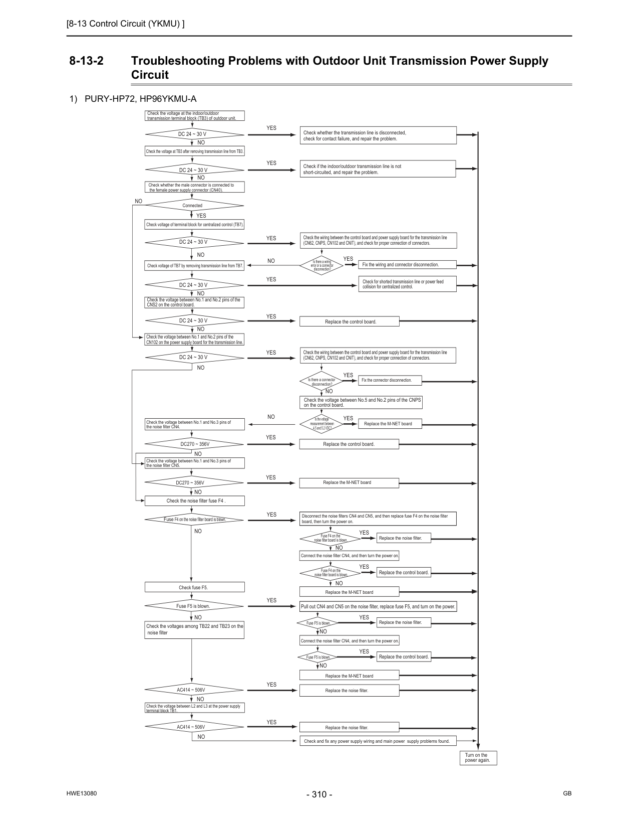
[8-13 Control Circuit (YKMU) ]
Hwe13080
Gb
8-13-2 Troubleshooting Problems with Outdoor Unit Transmission Power Supply Circuit1) Pury-Hp72, Hp96Ykmu-A
Yes
Yes
Yes
Yes
Yes
Yes
No
No
No
No
No
No
Dc270 ~ 356V
Ac414 ~ 506V
Fuse F4 on the noise filter board is blown.Ac414 ~ 506V
Yes
Yes
Yes
Yes
Yes
No
No
No
No
No
No
Yes
No
Yes
Yes
No
No
No
Yes
Yes
Yes
No
No
No
Yes
No
Yes
Check the voltage between L2 and L3 at the power supply terminal block TB1. Check the voltages among TB22 and TB23 on the noise filter Fuse F5 is blown. Fuse F5 is blown. Fuse F5 is blown. Check fuse F5. Pull out CN4 and CN5 on the noise filter, replace fuse F5, and turn on the power.Yes
Check the voltage at the indoor/outdoor transmission terminal block (TB3) of outdoor unit.Dc 24 ~ 30 V
Check the voltage at TB3 after removing transmission line from TB3.Dc 24 ~ 30 V
Dc 24 ~ 30 V
Dc 24 ~ 30 V
Dc 24 ~ 30 V
Dc 24 ~ 30 V
Check whether the male connector is connected to the female power supply connector (CN40). Connected Check voltage of terminal block for centralized control (TB7). Check voltage of TB7 by removing transmission line from TB7. Check the voltage between No.1 and No.2 pins of the CNS2 on the control board. Check the voltage between No.1 and No.3 pins of the noise filter CN4.Dc270 ~ 356V
Check the voltage between No.1 and No.3 pins of the noise filter CN5. Check the noise filter fuse F4 . Turn on the power again. Check and fix any power supply wiring and main power supply problems found. Replace the noise filter. Replace the noise filter. Replace the M-NET board Connect the noise filter CN4, and then turn the power on. Replace the control board. Replace the noise filter. Replace the noise filter. Replace the control board. Fuse F4 on the noise filter board is blown. Fuse F4 on the noise filter board is blown. Disconnect the noise filters CN4 and CN5, and then replace fuse F4 on the noise filter board, then turn the power on. Connect the noise filter CN4, and then turn the power on. Replace the M-NET board Replace the M-NET board Replace the control board. Is the voltage measurement between 4.5 and 5.2 VDC? Replace the M-NET board Check the voltage between No.5 and No.2 pins of the CNPS on the control board. Is there a connector disconnection? Fix the connector disconnection. Check whether the transmission line is disconnected, check for contact failure, and repair the problem. Check if the indoor/outdoor transmission line is not short-circuited, and repair the problem. Check the wiring between the control board and power supply board for the transmission line (CN62, CNPS, CN102 and CNIT), and check for proper connection of connectors. Check the wiring between the control board and power supply board for the transmission line (CN62, CNPS, CN102 and CNIT), and check for proper connection of connectors. Fix the wiring and connector disconnection. Check for shorted transmission line or power feed collision for centralized control. Replace the control board. Is there a wiring error or a connector disconnection? Check the voltage between No.1 and No.2 pins of the CN102 on the power supply board for the transmission line.
[8-14 Measures for Refrigerant Leakage ]
Hwe13080
Gb
8 Troubleshooting Based on Observed Symptoms 8-14 Measures for Refrigerant LeakageOn
[8-14 Measures for Refrigerant Leakage ]
Hwe13080
Gb
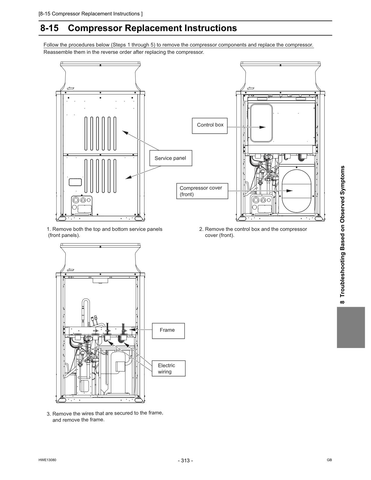
[8-15 Compressor Replacement Instructions ]
Hwe13080
Gb
8 Troubleshooting Based on Observed Symptoms 8-15 Compressor Replacement InstructionsFollow the procedures below (Steps 1 through 5) to remove the compressor components and replace the compressor. Reassemble them in the reverse order after replacing the compressor.
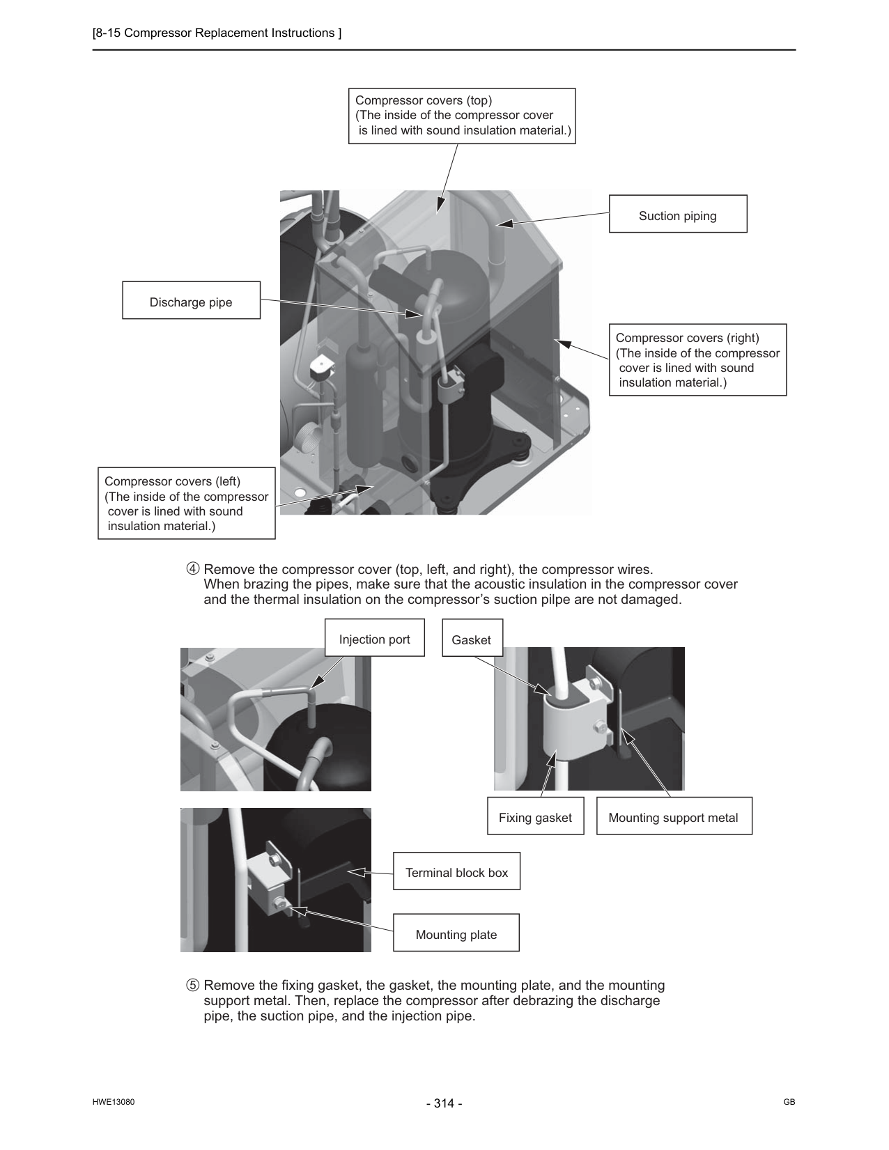
[8-15 Compressor Replacement Instructions ]
Hwe13080
Gb
Remove the compressor cover (top, left, and right), the compressor wires. When brazing the pipes, make sure that the acoustic insulation in the compressor cover and the thermal insulation on the compressor’s suction pilpe are not damaged. Remove the fixing gasket, the gasket, the mounting plate, and the mounting support metal. Then, replace the compressor after debrazing the discharge pipe, the suction pipe, and the injection pipe. 4 5 Compressor covers (top) (The inside of the compressor cover is lined with sound insulation material.) Suction piping Discharge pipe Compressor covers (right) (The inside of the compressor cover is lined with sound insulation material.) Compressor covers (left) (The inside of the compressor cover is lined with sound insulation material.) Injection port Fixing gasket Mounting support metal Terminal block box Mounting plate Gasket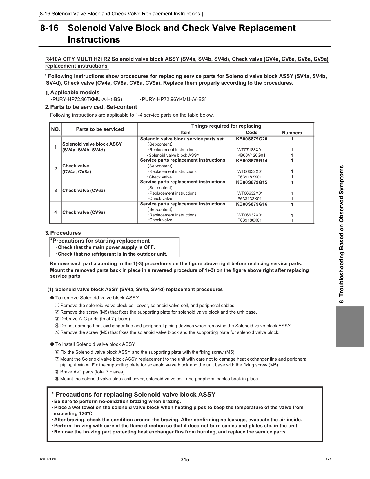
[8-16 Solenoid Valve Block and Check Valve Replacement Instructions ]
Hwe13080
Gb
8 Troubleshooting Based on Observed Symptoms 8-16 Solenoid Valve Block and Check Valve Replacement Instructions 1.Applicable models䊶Pury-Hp72,96Tkmu-A-H(-Bs)
䊶Pury-Hp72,96Ykmu-A(-Bs)
2.Parts to be serviced, Set-content Following instructions are applicable to 1-4 service parts on the table below. Numbers 1 1 1 1 1 1 1 1 1 1 1 1 3.Procedures *Precautions for starting replacement 䊶Check that the main power supply is OFF. 䊶Check that no refrigerant is in the outdoor unit. Remove each part according to the 1)-3) procedures on the figure above right before replacing service parts. Mount the removed parts back in place in a reversed procedure of 1)-3) on the figure above right after replacing service parts. (1) Solenoid valve block ASSY (SV4a, SV4b, SV4d) replacement procedures 䃂To remove Solenoid valve block ASSY 㽲Remove the solenoid valve block coil cover, solenoid valve coil, and peripheral cables. 㽳Remove the screw (M5) that fixes the supporting plate for solenoid valve block and the unit base. 㽴Debraze A-G parts (total 7 places). 㽵Do not damage heat exchanger fins and peripheral piping devices when removing the Solenoid valve block ASSY. 㽶Remove the screw (M5) that fixes the solenoid valve block and the supporting plate for solenoid valve block. 䃂To install Solenoid valve block ASSY 㽷Fix the Solenoid valve block ASSY and the supporting plate with the fixing screw (M5). 㽸Mount the Solenoid valve block ASSY replacement to the unit with care not to damage heat exchanger fins and peripheral piping devices. Fix the supporting plate for solenoid valve block and the unit base with the fixing screw (M5). 㽹Braze A-G parts (total 7 places). 㽺Mount the solenoid valve block coil cover, solenoid valve coil, and peripheral cables back in place. Things required for replacingNo.
e d oC
m e tI Parts to be serviced Solenoid valve block service parts set 䇭䇭䇭䇼Set-content䇽 1 Solenoid valve block ASSY (SV4a, SV4b, SV4d)Kb00S879G20
Wt07188X01
Kb00V126G01
䇭䇭䇭䊶Replacement instructions 䇭䇭䊶Solenoid valve block ASSYP633133X01
Kb00S879G15
Service parts replacement instructions Service parts replacement instructions 䇭䇭䇭䊶Check valve 䇭䇭䇭䇼Set-content䇽Kb00S879G14
P639183X01
Wt06632X01
Wt06632X01
Check valve (CV4a, CV8a) 䇭䇭䇭䊶Replacement instructions 3 Check valve (CV6a) 2 䇭䇭䊶Check valve 䇭䇭䇭䇼Set-content䇽 䇭䇭䇭䊶Replacement instructions 4 Check valve (CV9a) Service parts replacement instructionsKb00S879G16
䇭䇭䇭䇼Set-content䇽 䇭䇭䇭䊶Replacement instructionsWt06632X01
䇭䇭䇭䊶Check valveP639180X01
䇭* Precautions for replacing Solenoid valve block ASSY 䇭䊶Be sure to perform no-oxidation brazing when brazing. 䇭䊶Place a wet towel on the solenoid valve block when heating pipes to keep the temperature of the valve from exceeding 120ºC. 䇭䊶After brazing, check the condition around the brazing. After confirming no leakage, evacuate the air inside. 䇭䊶Perform brazing with care of the flame direction so that it does not burn cables and plates etc. in the unit. 䇭䊶Remove the brazing part protecting heat exchanger fins from burning, and replace the service parts.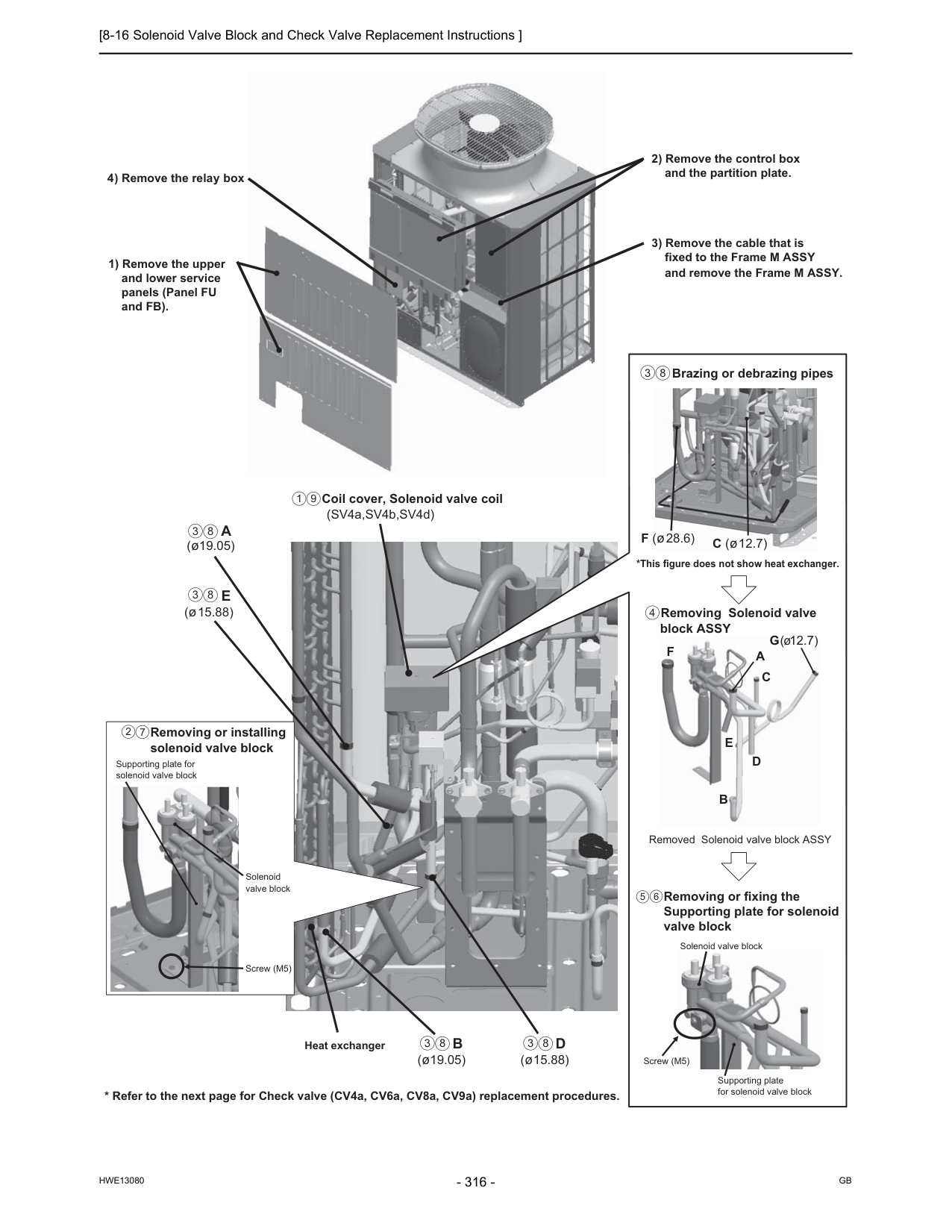
[8-16 Solenoid Valve Block and Check Valve Replacement Instructions ]
Hwe13080
Gb
3 8 3 8 3 8 3 8 1 9E
(ø15.88) Coil cover, Solenoid valve coil (SV4a,SV4b,SV4d)B
(ø19.05)D
(ø15.88)A
(ø19.05) Heat exchanger Removing or installing solenoid valve block 1) Remove the upper and lower service panels (Panel FU and FB). 3) Remove the cable that is fixed to the Frame M ASSY and remove the Frame M ASSY. 2) Remove the control box and the partition plate. 4) Remove the relay box Screw (M5) Supporting plate for solenoid valve block Solenoid valve block 2 7 Removed Solenoid valve block ASSY Removing or fixing the Supporting plate for solenoid valve block Removing Solenoid valve block ASSY Brazing or debrazing pipes *This figure does not show heat exchanger. C (ø12.7) F (ø28.6)F
B
E
D
C
A
G(ø12.7) Screw (M5) Supporting plate for solenoid valve block Solenoid valve block 5 6 4 3 8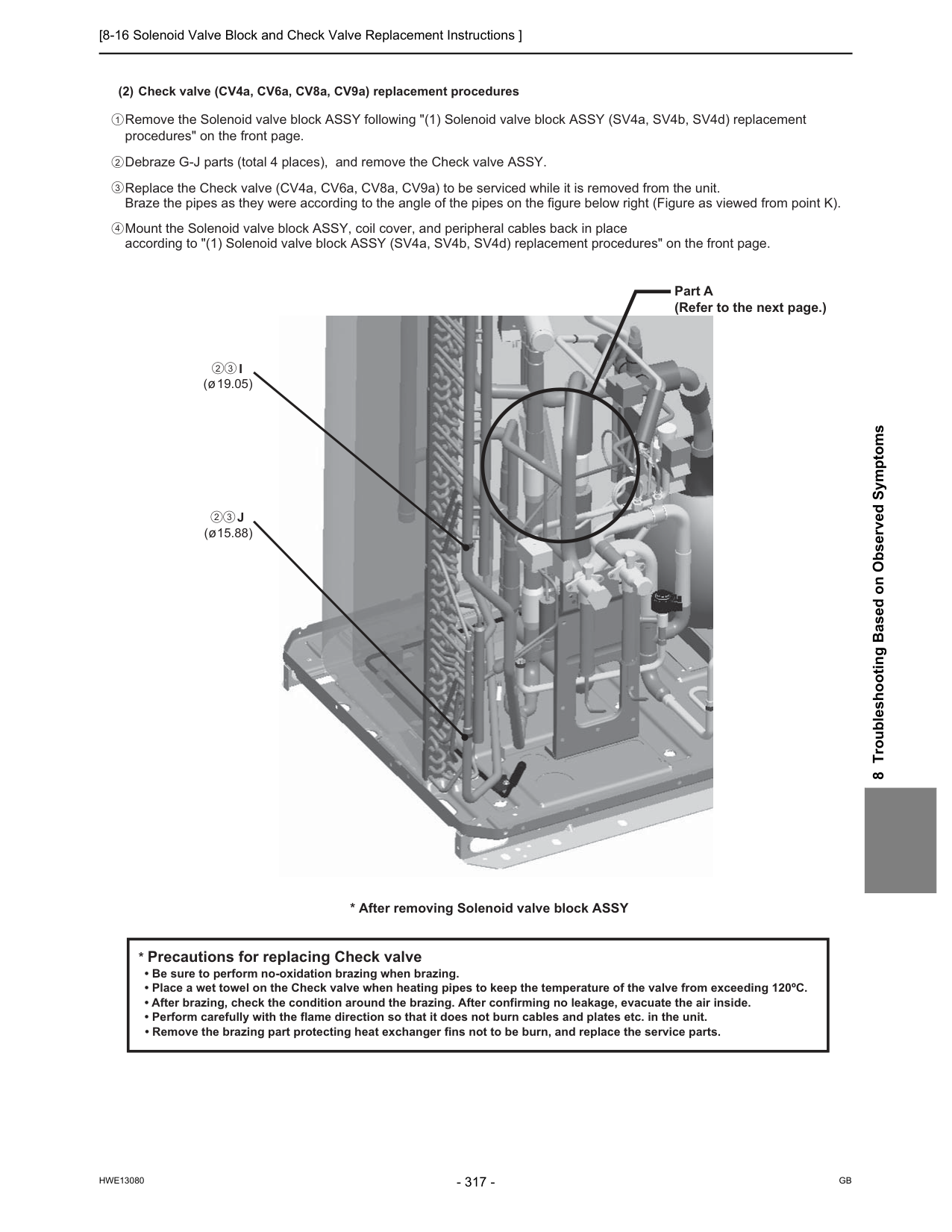
[8-16 Solenoid Valve Block and Check Valve Replacement Instructions ]
Hwe13080
Gb
8 Troubleshooting Based on Observed Symptoms 2 3 2 3 2 1 3 4 (2) Check valve (CV4a, CV6a, CV8a, CV9a) replacement procedures Remove the Solenoid valve block ASSY following "(1) Solenoid valve block ASSY (SV4a, SV4b, SV4d) replacement procedures" on the front page. Debraze G-J parts (total 4 places), and remove the Check valve ASSY. Replace the Check valve (CV4a, CV6a, CV8a, CV9a) to be serviced while it is removed from the unit. Braze the pipes as they were according to the angle of the pipes on the figure below right (Figure as viewed from point K). Mount the Solenoid valve block ASSY, coil cover, and peripheral cables back in place according to "(1) Solenoid valve block ASSY (SV4a, SV4b, SV4d) replacement procedures" on the front page.J
(ø15.88)I
(ø19.05)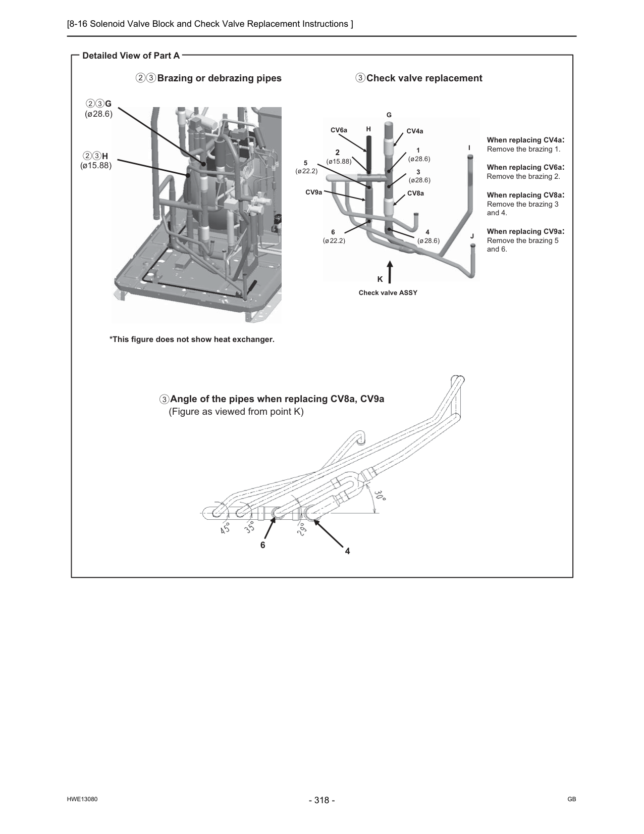
[8-16 Solenoid Valve Block and Check Valve Replacement Instructions ]
Hwe13080
Gb
6 4 Detailed View of Part A Check valve replacement When replacing CV4a: Remove the brazing 1. When replacing CV6a: Remove the brazing 2. When replacing CV8a: Remove the brazing 3 and 4. When replacing CV9a: Remove the brazing 5 and 6. Angle of the pipes when replacing CV8a, CV9a (Figure as viewed from point K)I
J
CV4a CV8a CV9a CV6a 5 ( ( ø22.2) 6 ø22.2) 3 (ø28.6) 4 (ø28.6) 1 (ø28.6) 2 (ø15.88)G
H
Check valve ASSYK
Brazing or debrazing pipes *This figure does not show heat exchanger.G
(ø28.6)H
(ø15.88) 2 3 2 3 2 3 3 3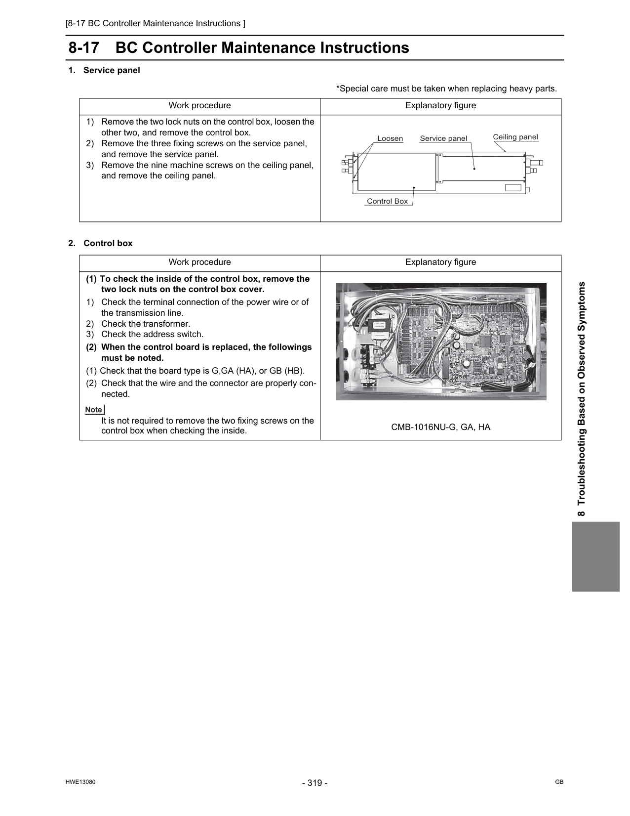
[8-17 BC Controller Maintenance Instructions ]
Hwe13080
Gb
8 Troubleshooting Based on Observed Symptoms 8-17 BC Controller Maintenance InstructionsCmb-1016Nu-G, Ga, Ha
Loosen Service panel Control Box Ceiling panel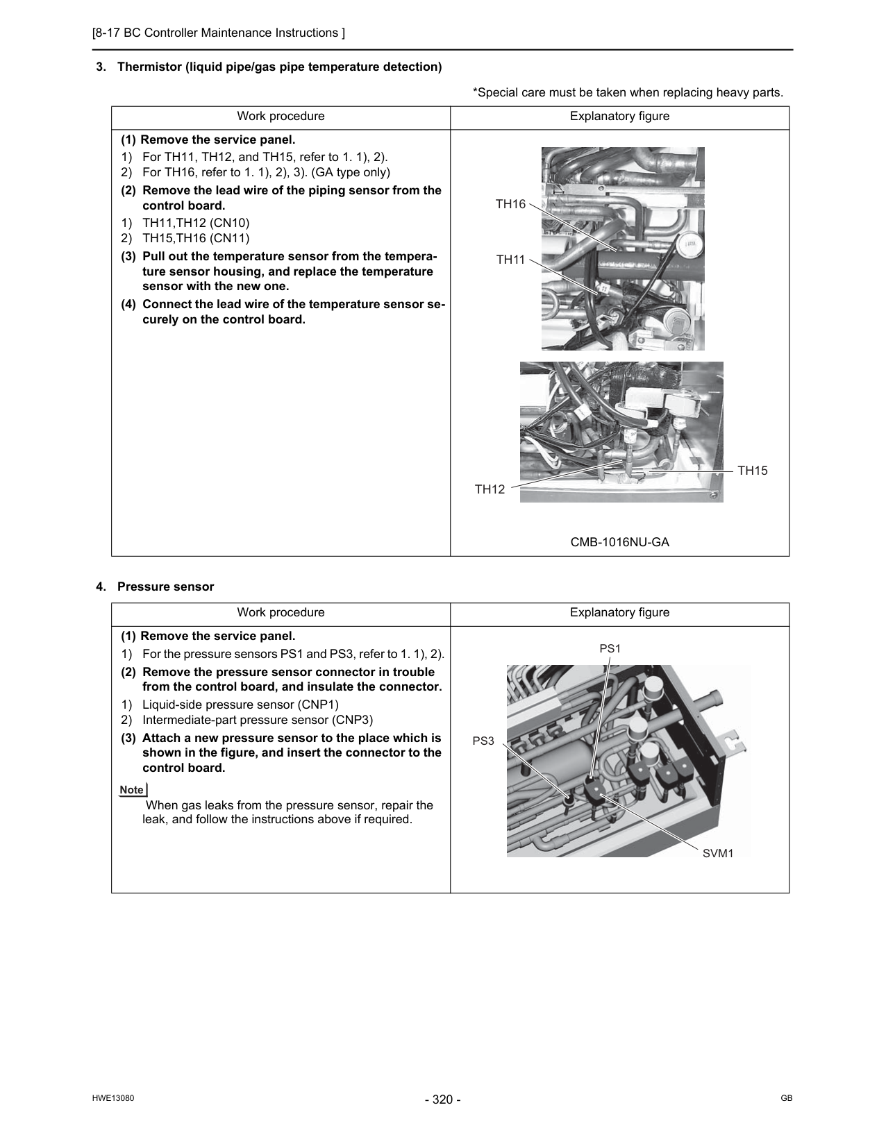
[8-17 BC Controller Maintenance Instructions ]
Hwe13080
Gb
1) Th11,Th12 (Cn10)
2) Th15,Th16 (Cn11)
(3) Pull out the temperature sensor from the tempera- ture sensor housing, and replace the temperature sensor with the new one. (4) Connect the lead wire of the temperature sensor se- curely on the control board.Cmb-1016Nu-Ga
Work procedure Explanatory figure (1) Remove the service panel. 1) For the pressure sensors PS1 and PS3, refer to 1. 1), 2). (2) Remove the pressure sensor connector in trouble from the control board, and insulate the connector. 1) Liquid-side pressure sensor (CNP1) 2) Intermediate-part pressure sensor (CNP3) (3) Attach a new pressure sensor to the place which is shown in the figure, and insert the connector to the control board. When gas leaks from the pressure sensor, repair the leak, and follow the instructions above if required.Th15
Th12
Th16
Th11
Svm1
Ps1
Ps3
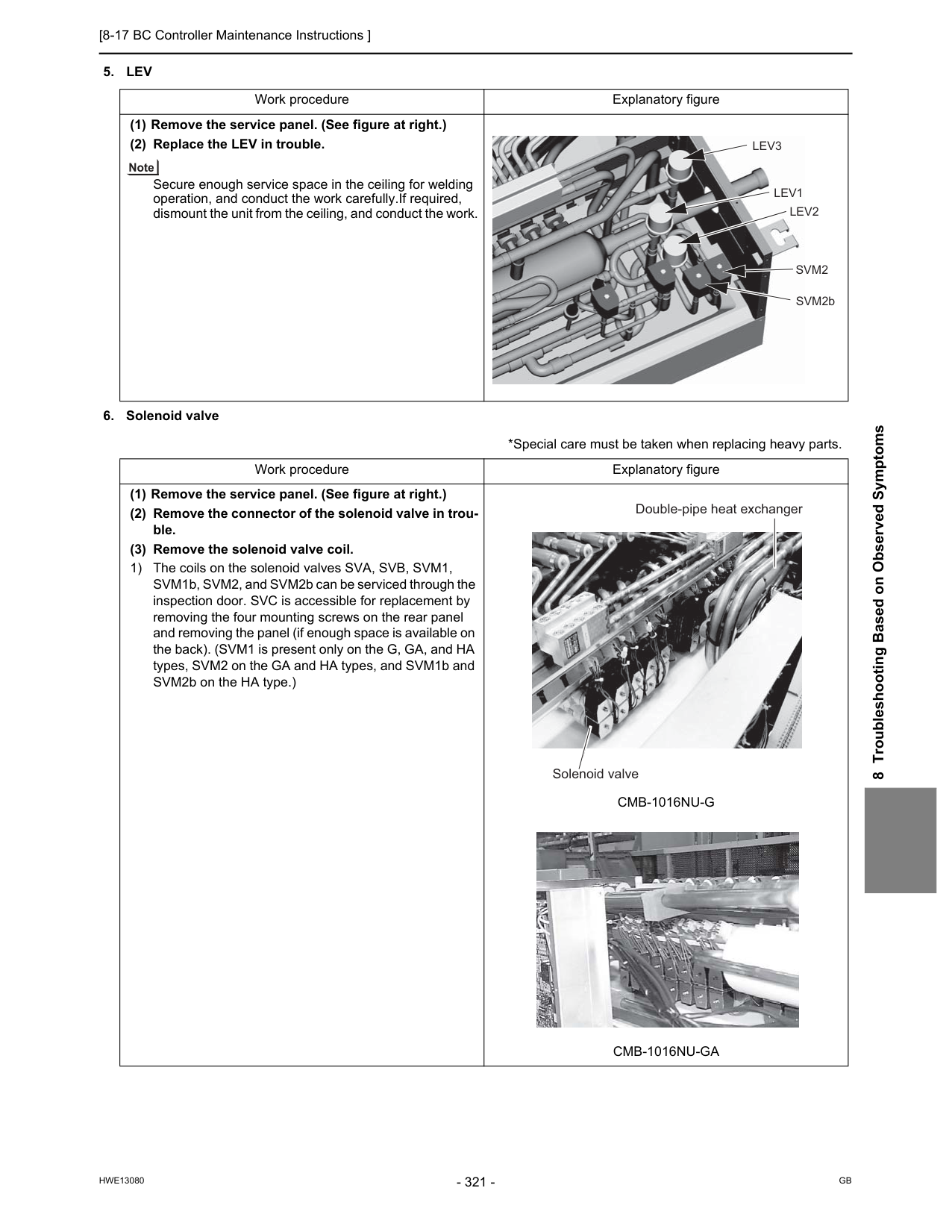
[8-17 BC Controller Maintenance Instructions ]
Hwe13080
Gb
8 Troubleshooting Based on Observed Symptoms5. Lev
Cmb-1016Nu-G
Cmb-1016Nu-Ga
Lev3
Lev1
Lev2
Svm2
SVM2b Double-pipe heat exchanger Solenoid valve
[8-18 Troubleshooting Problems Using the LED Status Indicators on the Outdoor Unit ]
Hwe13080
Gb
8-18 Troubleshooting Problems Using the LED Status Indicators on the Outdoor Unit If the LED error display appear as follows while all the SW4 switches and SW6-10 are set to OFF, check the items under the ap- plicable item numbers below.
Hwe13080
Gb
Chapter 9 LED Status Indicators on the Outdoor Unit Circuit Board 9-1 LED Status Indicators....................................................................................................................... 325 9-1-1 How to Read the LED ......................................................................................................................... 325 9-1-2 Initial LED Display............................................................................................................................... 326 9-1-3 Clock Memory Function ...................................................................................................................... 327 9-2 LED Status Indicators Table ............................................................................................................ 328
Hwe13080
Gb
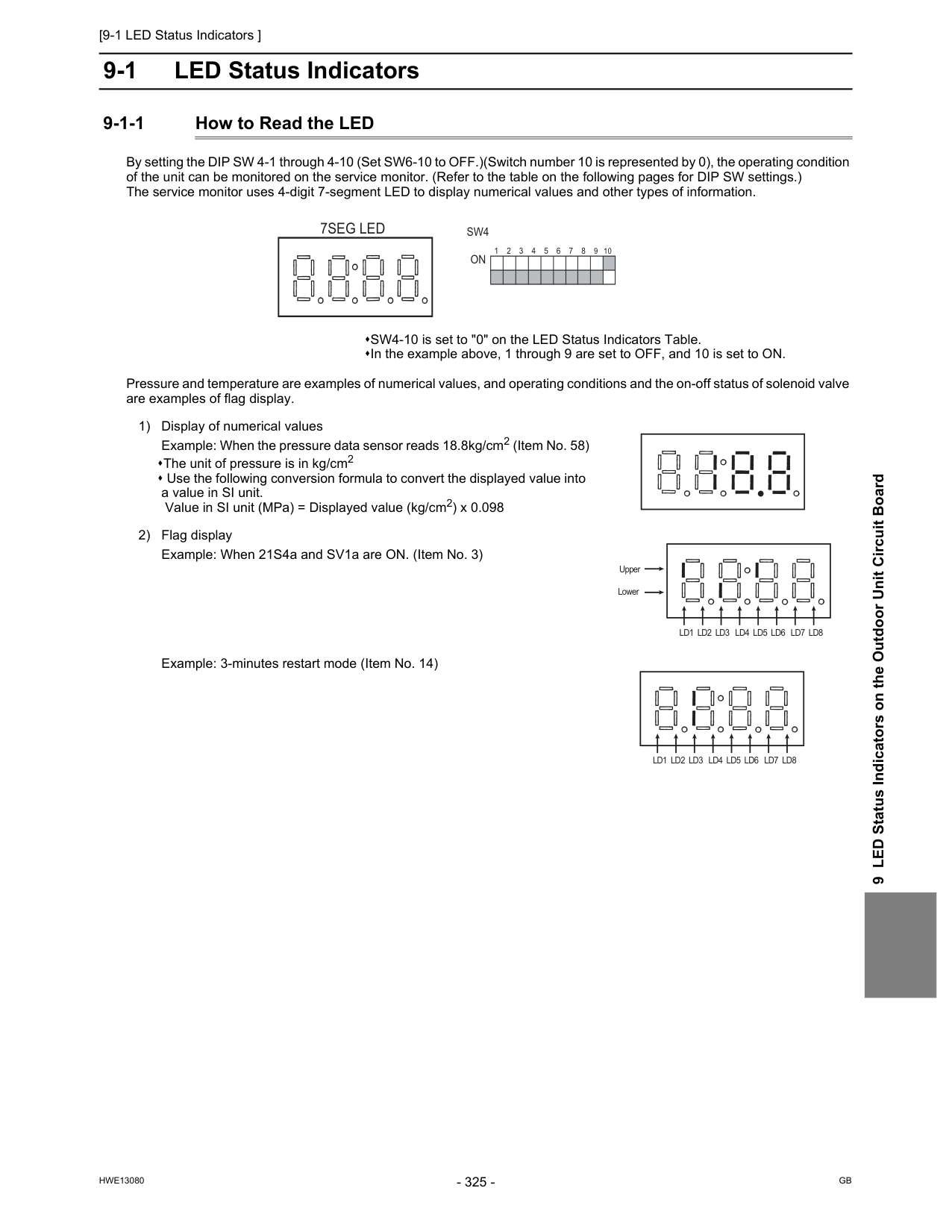
[9-1 LED Status Indicators ]
Hwe13080
Gb
9 LED Status Indicators on the Outdoor Unit Circuit Board 9 LED Status Indicators on the Outdoor Unit Circuit Board 9-1 LED Status Indicators 9-1-1 How to Read the LED By setting the DIP SW 4-1 through 4-10 (Set SW6-10 to OFF.)(Switch number 10 is represented by 0), the operating condition of the unit can be monitored on the service monitor. (Refer to the table on the following pages for DIP SW settings.) The service monitor uses 4-digit 7-segment LED to display numerical values and other types of information. Pressure and temperature are examples of numerical values, and operating conditions and the on-off status of solenoid valve are examples of flag display. SW4-10 is set to "0" on the LED Status Indicators Table. In the example above, 1 through 9 are set to OFF, and 10 is set to ON. 1) Display of numerical values Example: When the pressure data sensor reads 18.8kg/cm2 (Item No. 58) The unit of pressure is in kg/cm2 Use the following conversion formula to convert the displayed value into a value in SI unit. Value in SI unit (MPa) = Displayed value (kg/cm2) x 0.098 2) Flag display Example: When 21S4a and SV1a are ON. (Item No. 3) Example: 3-minutes restart mode (Item No. 14)Sw4
On
1 2 3 4 5 6 7 8 9 107Seg Led
Ld1 Ld2 Ld3 Ld4 Ld5 Ld6 Ld7 Ld8
Upper LowerLd1 Ld2 Ld3 Ld4 Ld5 Ld6 Ld7 Ld8
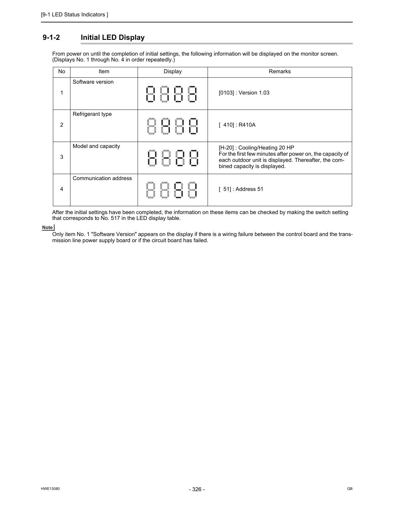
[9-1 LED Status Indicators ]
Hwe13080
Gb
9-1-2 Initial LED Display From power on until the completion of initial settings, the following information will be displayed on the monitor screen. (Displays No. 1 through No. 4 in order repeatedly.) After the initial settings have been completed, the information on these items can be checked by making the switch setting that corresponds to No. 517 in the LED display table. Only item No. 1 "Software Version" appears on the display if there is a wiring failure between the control board and the trans- mission line power supply board or if the circuit board has failed. No Item Display Remarks 1 Software version [0103] : Version 1.03 2 Refrigerant type[ 410] : R410A
3 Model and capacity [H-20] : Cooling/Heating 20 HP For the first few minutes after power on, the capacity of each outdoor unit is displayed. Thereafter, the com- bined capacity is displayed. 4 Communication address [ 51] : Address 51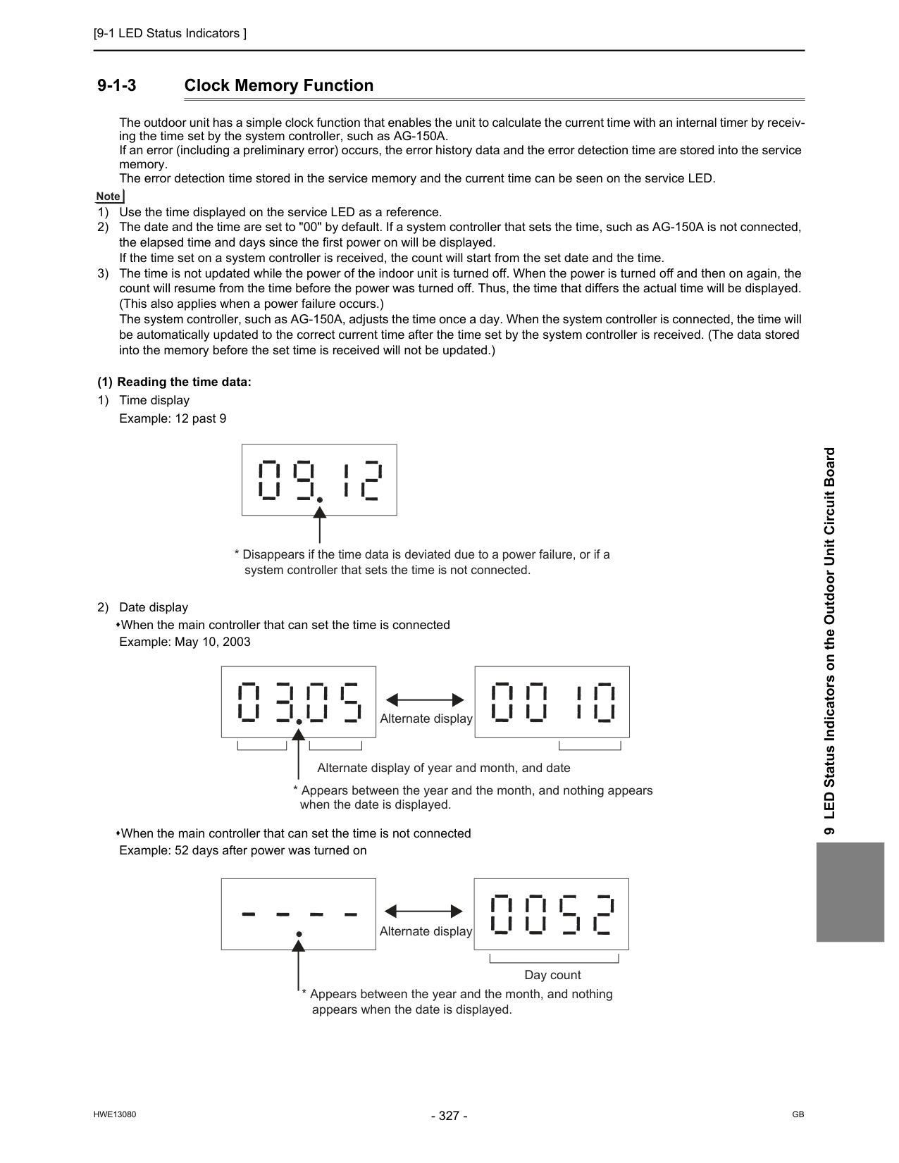
[9-1 LED Status Indicators ]
Hwe13080
Gb
9 LED Status Indicators on the Outdoor Unit Circuit Board 9-1-3 Clock Memory Function The outdoor unit has a simple clock function that enables the unit to calculate the current time with an internal timer by receiv- ing the time set by the system controller, such as AG-150A. If an error (including a preliminary error) occurs, the error history data and the error detection time are stored into the service memory. The error detection time stored in the service memory and the current time can be seen on the service LED. 1) Use the time displayed on the service LED as a reference. 2) The date and the time are set to "00" by default. If a system controller that sets the time, such as AG-150A is not connected, the elapsed time and days since the first power on will be displayed. If the time set on a system controller is received, the count will start from the set date and the time. 3) The time is not updated while the power of the indoor unit is turned off. When the power is turned off and then on again, the count will resume from the time before the power was turned off. Thus, the time that differs the actual time will be displayed. (This also applies when a power failure occurs.) The system controller, such as AG-150A, adjusts the time once a day. When the system controller is connected, the time will be automatically updated to the correct current time after the time set by the system controller is received. (The data stored into the memory before the set time is received will not be updated.) (1) Reading the time data: 1) Time display Example: 12 past 9 2) Date display When the main controller that can set the time is connected Example: May 10, 2003 When the main controller that can set the time is not connected Example: 52 days after power was turned on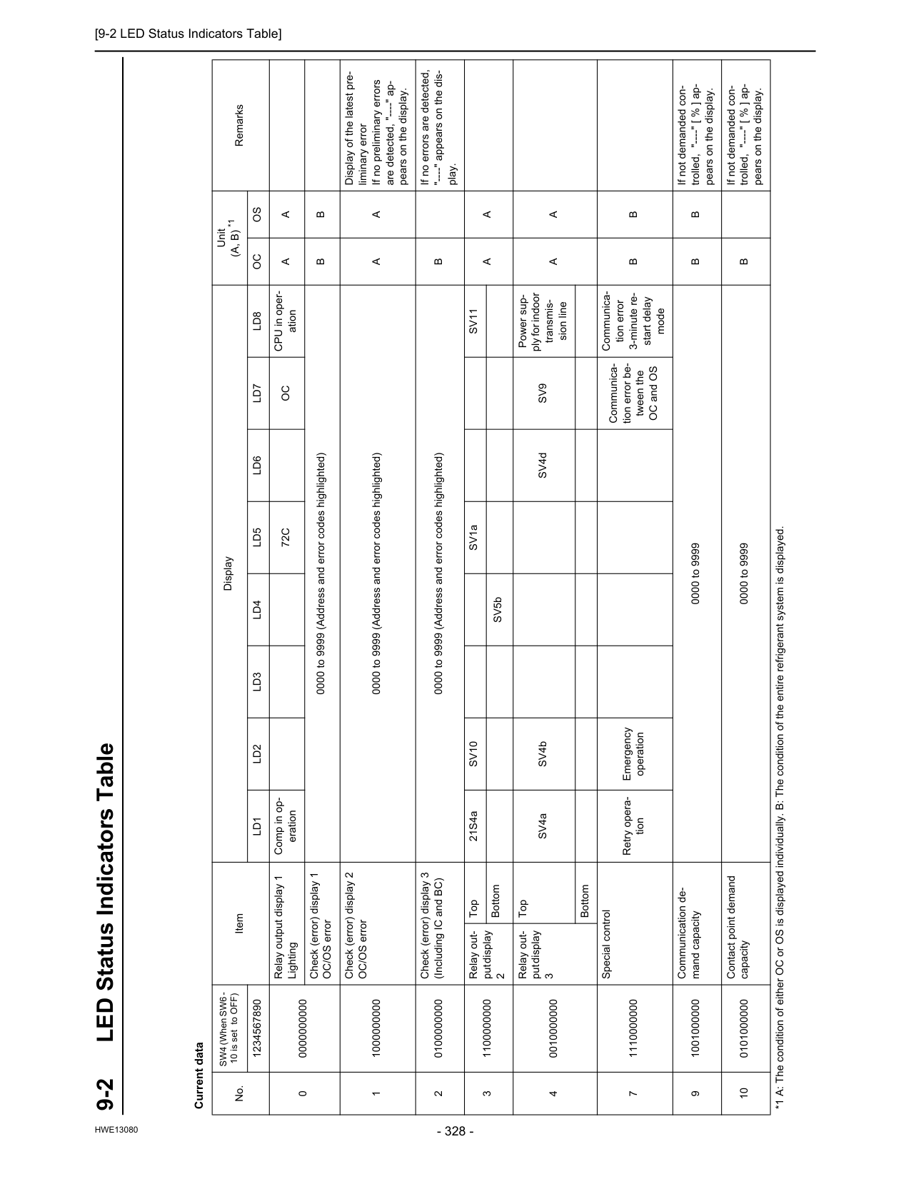
[9-2 LED Status Indicators Table]
Hwe13080
10LED Status Indicators on the Outdoor Unit Circuit Board 9-2 LED Status Indicators Table Current data No. SW4 (When SW6 - 10 is set to OFF) Item Display Unit(A, B) *1
Remarks 1234567890Ld1
Ld2
Ld3
Ld4
Ld5
Ld6
Ld7
Ld8
Oc
Os
0 0000000000 Relay output display 1 Lighting Comp in op- eration72C
Oc
CPU in oper- ationA
A
Check (error) display 1 OC/OS error 0000 to 9999 (Address and error codes highlighted)B
B
1 1000000000 Check (error) display 2 OC/OS error 0000 to 9999 (Address and error codes highlighted)A
A
Display of the latest pre- liminary error If no preliminary errors are detected, "----" ap- pears on the display. 2 0100000000 Check (error) display 3 (Including IC and BC) 0000 to 9999 (Address and error codes highlighted)B
If no errors are detected, "----" appears on the dis- play. 3 1100000000 Relay out- put display 2 Top 21S4aSv10
SV1aSv11
A
A
Bottom SV5b 4 0010000000 Relay out- put display 3 Top SV4a SV4b SV4dSv9
Power sup- ply for indoor transmis- sion lineA
A
Bottom 7 1110000000 Special control Retry opera- tion Emergency operation Communica- tion error be- tween the OC and OS Communica- tion error 3-minute re- start delay modeB
B
9 1001000000 Communication de- mand capacity 0000 to 9999B
B
If not demanded con- trolled, "----" [ % ] ap- pears on the display. 10 0101000000 Contact point demand capacity 0000 to 9999B
If not demanded con- trolled, "----" [ % ] ap- pears on the display. *1 A: The condition of either OC or OS is displayed individually. B: The condition of the entire refrigerant system is displayed.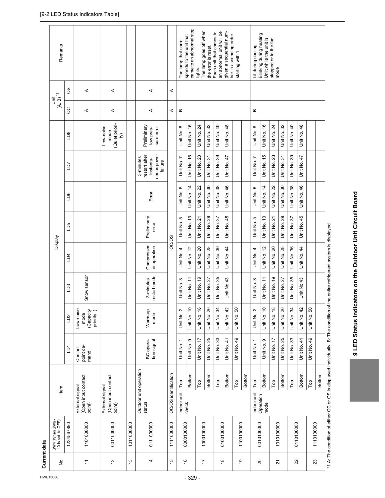
[9-2 LED Status Indicators Table]
Hwe13080
9 LED Status Indicators on the Outdoor Unit Circuit Board 11 1101000000 External signal (Open input contact point) Contact point de- mand Low-noise mode (Capacity priority ) Snow sensorA
A
12 0011000000 External signal (Open input contact point) Low-noise mode (Quiet priori- ty)A
A
13 1011000000 14 0111000000 Outdoor unit operation status BC opera- tion signal Warm-up mode 3-minutes restart mode Compressor in operation Preliminary error Error 3-minutes restart after instanta- neous power failure Preliminary low pres- sure errorA
A
15 1111000000 OC/OS identificationOc/Os
A
A
16 0000100000 Indoor unit check Top Unit No. 1 Unit No. 2 Unit No. 3 Unit No. 4 Unit No. 5 Unit No. 6 Unit No. 7 Unit No. 8B
The lamp that corre- sponds to the unit that came to an abnormal stop lights. The lamp goes off when the error is reset. Each unit that comes to an abnormal unit will be given a sequential num- ber in ascending order starting with 1. Bottom Unit No. 9 Unit No. 10 Unit No. 11 Unit No. 12 Unit No. 13 Unit No. 14 Unit No. 15 Unit No. 16 17 1000100000 Top Unit No. 17 Unit No. 18 Unit No. 19 Unit No. 20 Unit No. 21 Unit No. 22 Unit No. 23 Unit No. 24 Bottom Unit No. 25 Unit No. 26 Unit No. 27 Unit No. 28 Unit No. 29 Unit No. 30 Unit No. 31 Unit No. 32 18 0100100000 Top Unit No. 33 Unit No. 34 Unit No. 35 Unit No. 36 Unit No. 37 Unit No. 38 Unit No. 39 Unit No. 40 Bottom Unit No. 41 Unit No. 42 Unit No.43 Unit No. 44 Unit No. 45 Unit No. 46 Unit No. 47 Unit No. 48 19 1100100000 Top Unit No. 49 Unit No. 50 Bottom 20 0010100000 Indoor unit Operation mode Top Unit No. 1 Unit No. 2 Unit No. 3 Unit No. 4 Unit No. 5 Unit No. 6 Unit No. 7 Unit No. 8B
Lit during cooling Blinking during heating Unlit while the unit is stopped or in the fan mode Bottom Unit No. 9 Unit No. 10 Unit No. 11 Unit No. 12 Unit No. 13 Unit No. 14 Unit No. 15 Unit No. 16 21 1010100000 Top Unit No. 17 Unit No. 18 Unit No. 19 Unit No. 20 Unit No. 21 Unit No. 22 Unit No. 23 Unit No. 24 Bottom Unit No. 25 Unit No. 26 Unit No. 27 Unit No. 28 Unit No. 29 Unit No. 30 Unit No. 31 Unit No. 32 22 0110100000 Top Unit No. 33 Unit No. 34 Unit No. 35 Unit No. 36 Unit No. 37 Unit No. 38 Unit No. 39 Unit No. 40 Bottom Unit No. 41 Unit No. 42 Unit No.43 Unit No. 44 Unit No. 45 Unit No. 46 Unit No. 47 Unit No. 48 23 1110100000 Top Unit No. 49 Unit No. 50 Bottom Current data No. SW4 (When SW6 - 10 is set to OFF) Item Display Unit(A, B) *1
Remarks 1234567890Ld1
Ld2
Ld3
Ld4
Ld5
Ld6
Ld7
Ld8
Oc
Os
*1 A: The condition of either OC or OS is displayed individually. B: The condition of the entire refrigerant system is displayed.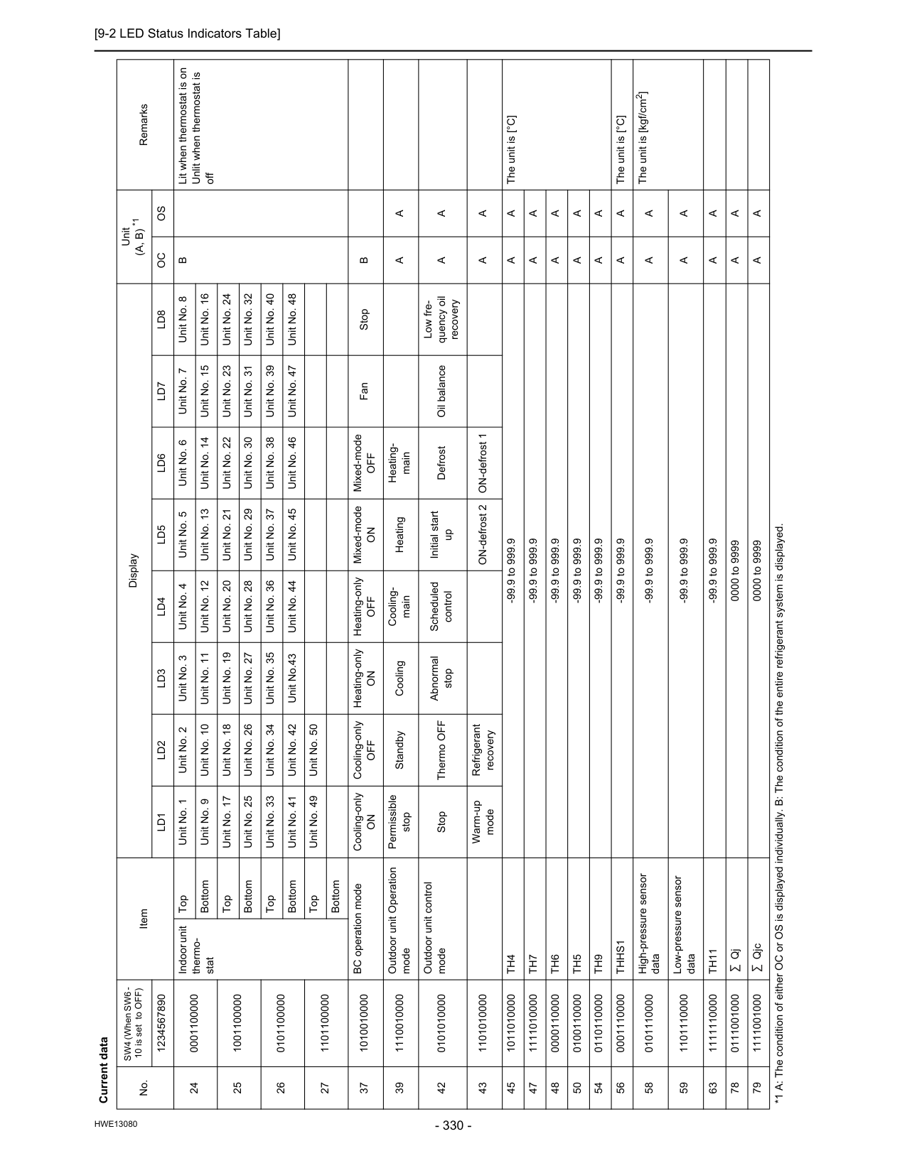
[9-2 LED Status Indicators Table]
Hwe13080
24 0001100000 Indoor unit thermo- stat Top Unit No. 1 Unit No. 2 Unit No. 3 Unit No. 4 Unit No. 5 Unit No. 6 Unit No. 7 Unit No. 8B
Lit when thermostat is on Unlit when thermostat is off Bottom Unit No. 9 Unit No. 10 Unit No. 11 Unit No. 12 Unit No. 13 Unit No. 14 Unit No. 15 Unit No. 16 25 1001100000 Top Unit No. 17 Unit No. 18 Unit No. 19 Unit No. 20 Unit No. 21 Unit No. 22 Unit No. 23 Unit No. 24 Bottom Unit No. 25 Unit No. 26 Unit No. 27 Unit No. 28 Unit No. 29 Unit No. 30 Unit No. 31 Unit No. 32 26 0101100000 Top Unit No. 33 Unit No. 34 Unit No. 35 Unit No. 36 Unit No. 37 Unit No. 38 Unit No. 39 Unit No. 40 Bottom Unit No. 41 Unit No. 42 Unit No.43 Unit No. 44 Unit No. 45 Unit No. 46 Unit No. 47 Unit No. 48 27 1101100000 Top Unit No. 49 Unit No. 50 Bottom 37 1010010000 BC operation mode Cooling-onlyOn
Cooling-onlyOff
Heating-onlyOn
Heating-onlyOff
Mixed-modeOn
Mixed-modeOff
Fan StopB
39 1110010000 Outdoor unit Operation mode Permissible stop Standby Cooling Cooling- main Heating Heating- mainA
A
42 0101010000 Outdoor unit control mode Stop Thermo OFF Abnormal stop Scheduled control Initial start up Defrost Oil balance Low fre- quency oil recoveryA
A
43 1101010000 Warm-up mode Refrigerant recovery ON-defrost 2 ON-defrost 1A
A
45 1011010000Th4
-99.9 to 999.9A
A
The unit is [°C] 47 1111010000Th7
-99.9 to 999.9A
A
48 0000110000Th6
-99.9 to 999.9A
A
50 0100110000Th5
-99.9 to 999.9A
A
54 0110110000Th9
-99.9 to 999.9A
A
56 0001110000Thhs1
-99.9 to 999.9A
A
The unit is [°C] 58 0101110000 High-pressure sensor data -99.9 to 999.9A
A
The unit is [kgf/cm2] 59 1101110000 Low-pressure sensor data -99.9 to 999.9A
A
63 1111110000Th11
-99.9 to 999.9A
A
78 0111001000 Qj 0000 to 9999A
A
79 1111001000 Qjc 0000 to 9999A
A
Current data No. SW4 (When SW6 - 10 is set to OFF) Item Display Unit(A, B) *1
Remarks 1234567890Ld1
Ld2
Ld3
Ld4
Ld5
Ld6
Ld7
Ld8
Oc
Os
*1 A: The condition of either OC or OS is displayed individually. B: The condition of the entire refrigerant system is displayed.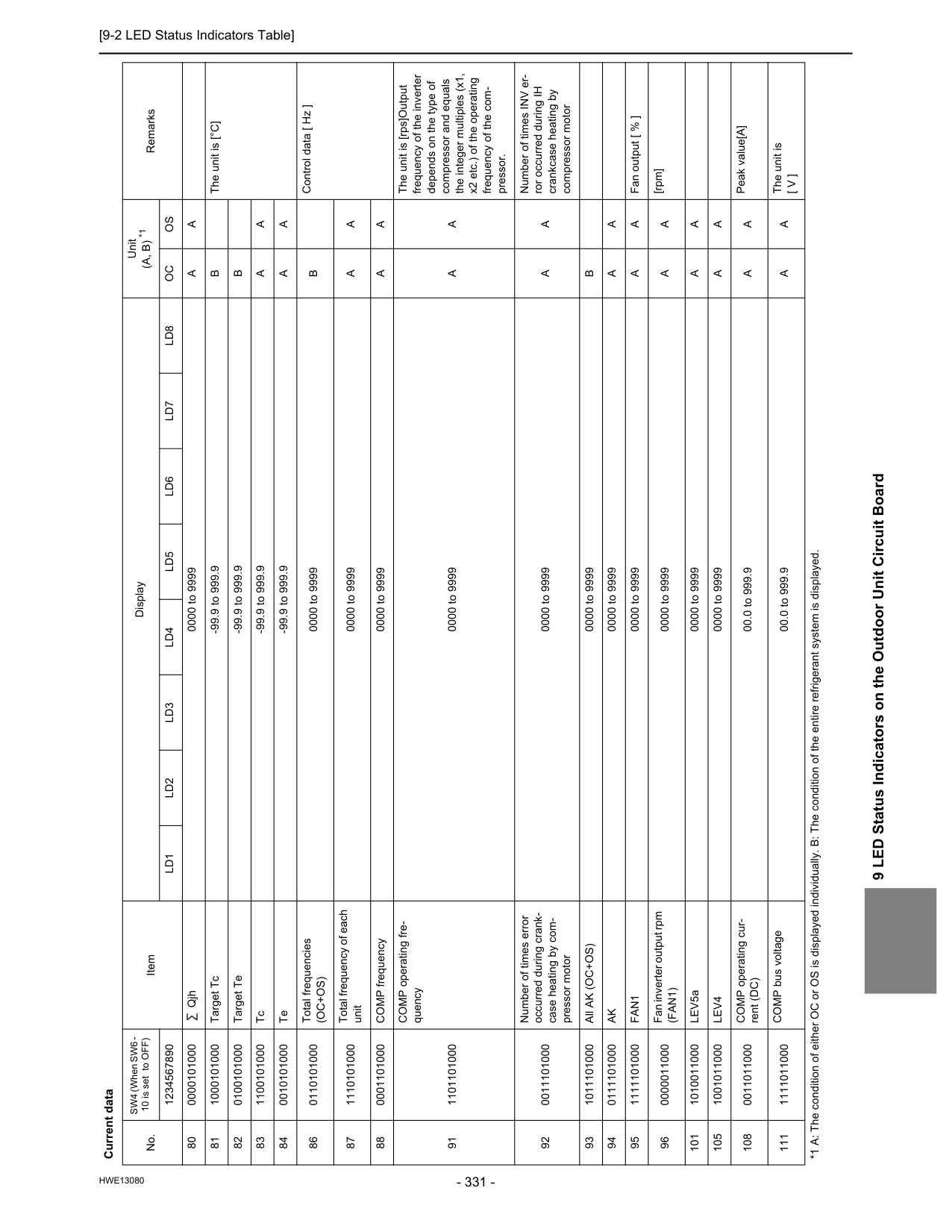
[9-2 LED Status Indicators Table]
Hwe13080
9 LED Status Indicators on the Outdoor Unit Circuit Board 80 0000101000 Qjh 0000 to 9999A
A
81 1000101000 Target Tc -99.9 to 999.9B
The unit is [°C] 82 0100101000 Target Te -99.9 to 999.9B
83 1100101000 Tc -99.9 to 999.9A
A
84 0010101000 Te -99.9 to 999.9A
A
86 0110101000 Total frequencies(Oc+Os)
0000 to 9999B
Control data [ Hz ] 87 1110101000 Total frequency of each unit 0000 to 9999A
A
88 0001101000 COMP frequency 0000 to 9999A
A
91 1101101000 COMP operating fre- quency 0000 to 9999A
A
The unit is [rps]Output frequency of the inverter depends on the type of compressor and equals the integer multiples (x1, x2 etc.) of the operating frequency of the com- pressor. 92 0011101000 Number of times error occurred during crank- case heating by com- pressor motor 0000 to 9999A
A
Number of times INV er- ror occurred during IH crankcase heating by compressor motor 93 1011101000 All AK (OC+OS) 0000 to 9999B
94 0111101000Ak
0000 to 9999A
A
95 1111101000Fan1
0000 to 9999A
A
Fan output [ % ] 96 0000011000 Fan inverter output rpm(Fan1)
0000 to 9999A
A
[rpm] 101 1010011000 LEV5a 0000 to 9999A
A
105 1001011000Lev4
0000 to 9999A
A
108 0011011000 COMP operating cur- rent (DC) 00.0 to 999.9A
A
Peak value[A] 111 1111011000 COMP bus voltage 00.0 to 999.9A
A
The unit is[ V ]
Current data No. SW4 (When SW6 - 10 is set to OFF) Item Display Unit(A, B) *1
Remarks 1234567890Ld1
Ld2
Ld3
Ld4
Ld5
Ld6
Ld7
Ld8
Oc
Os
*1 A: The condition of either OC or OS is displayed individually. B: The condition of the entire refrigerant system is displayed.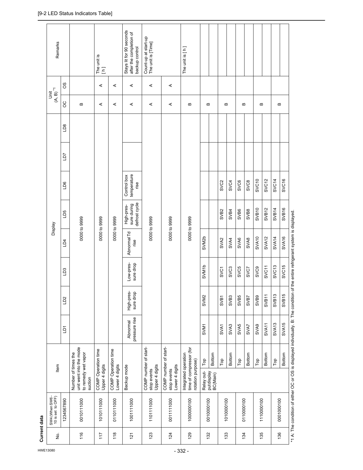
[9-2 LED Status Indicators Table]
Hwe13080
116 0010111000 Number of times the unit went into the mode to remedy wet vapor suction 0000 to 9999B
117 1010111000 COMP Operation time Upper 4 digits 0000 to 9999A
A
The unit is [ h ] 118 0110111000 COMP Operation time Lower 4 digits 0000 to 9999A
A
121 1001111000 Backup mode Abnormal pressure rise High-pres- sure drop Low-pres- sure drop Abnormal Td rise High-pres- sure during defrost cycle Control box temperature riseA
A
Stays lit for 90 seconds after the completion of backup control 123 1101111000 COMP number of start- stop events Upper 4 digits 0000 to 9999A
A
Count-up at start-up The unit is [Time] 124 0011111000 COMP number of start- stop events Lower 4 digits 0000 to 9999A
A
129 1000000100 Integrated operation time of compressor (for rotation purpose) 0000 to 9999B
The unit is [ h ] 132 0010000100 Relay out- put display BC(Main) TopSvm1
Svm2
SVM1b SVM2bB
Bottom 133 1010000100 TopSva1
Svb1
Svc1
Sva2
Svb2
Svc2
B
BottomSva3
Svb3
Svc3
Sva4
Svb4
Svc4
134 0110000100 TopSva5
Svb5
Svc5
Sva6
Svb6
Svc6
B
BottomSva7
Svb7
Svc7
Sva8
Svb8
Svc8
135 1110000100 TopSva9
Svb9
Svc9
Sva10
Svb10
Svc10
B
BottomSva11
Svb11
Svc11
Sva12
Svb12
Svc12
136 0001000100 TopSva13
Svb13
Svc13
Sva14
Svb14
Svc14
B
BottomSva15
Svb15
Svc15
Sva16
Svb16
Svc16
Current data No. SW4 (When SW6 - 10 is set to OFF) Item Display Unit(A, B) *1
Remarks 1234567890Ld1
Ld2
Ld3
Ld4
Ld5
Ld6
Ld7
Ld8
Oc
Os
*1 A: The condition of either OC or OS is displayed individually. B: The condition of the entire refrigerant system is displayed.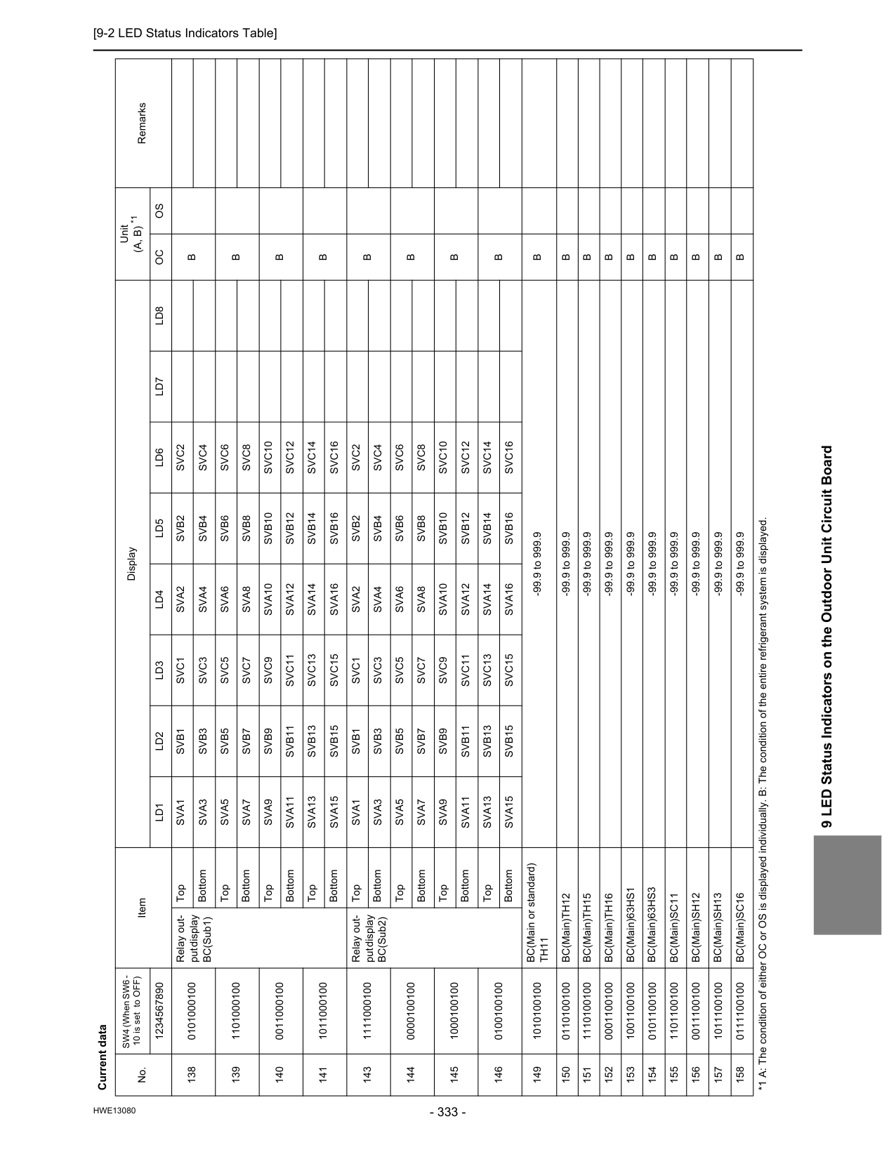
[9-2 LED Status Indicators Table]
Hwe13080
9 LED Status Indicators on the Outdoor Unit Circuit Board 138 0101000100 Relay out- put display BC(Sub1) TopSva1
Svb1
Svc1
Sva2
Svb2
Svc2
B
BottomSva3
Svb3
Svc3
Sva4
Svb4
Svc4
139 1101000100 TopSva5
Svb5
Svc5
Sva6
Svb6
Svc6
B
BottomSva7
Svb7
Svc7
Sva8
Svb8
Svc8
140 0011000100 TopSva9
Svb9
Svc9
Sva10
Svb10
Svc10
B
BottomSva11
Svb11
Svc11
Sva12
Svb12
Svc12
141 1011000100 TopSva13
Svb13
Svc13
Sva14
Svb14
Svc14
B
BottomSva15
Svb15
Svc15
Sva16
Svb16
Svc16
143 1111000100 Relay out- put display BC(Sub2) TopSva1
Svb1
Svc1
Sva2
Svb2
Svc2
B
BottomSva3
Svb3
Svc3
Sva4
Svb4
Svc4
144 0000100100 TopSva5
Svb5
Svc5
Sva6
Svb6
Svc6
B
BottomSva7
Svb7
Svc7
Sva8
Svb8
Svc8
145 1000100100 TopSva9
Svb9
Svc9
Sva10
Svb10
Svc10
B
BottomSva11
Svb11
Svc11
Sva12
Svb12
Svc12
146 0100100100 TopSva13
Svb13
Svc13
Sva14
Svb14
Svc14
B
BottomSva15
Svb15
Svc15
Sva16
Svb16
Svc16
149 1010100100 BC(Main or standard)Th11
-99.9 to 999.9B
150 0110100100 BC(Main)TH12 -99.9 to 999.9B
151 1110100100 BC(Main)TH15 -99.9 to 999.9B
152 0001100100 BC(Main)TH16 -99.9 to 999.9B
153 1001100100 BC(Main)63HS1 -99.9 to 999.9B
154 0101100100 BC(Main)63HS3 -99.9 to 999.9B
155 1101100100 BC(Main)SC11 -99.9 to 999.9B
156 0011100100 BC(Main)SH12 -99.9 to 999.9B
157 1011100100 BC(Main)SH13 -99.9 to 999.9B
158 0111100100 BC(Main)SC16 -99.9 to 999.9B
Current data No. SW4 (When SW6 - 10 is set to OFF) Item Display Unit(A, B) *1
Remarks 1234567890Ld1
Ld2
Ld3
Ld4
Ld5
Ld6
Ld7
Ld8
Oc
Os
*1 A: The condition of either OC or OS is displayed individually. B: The condition of the entire refrigerant system is displayed.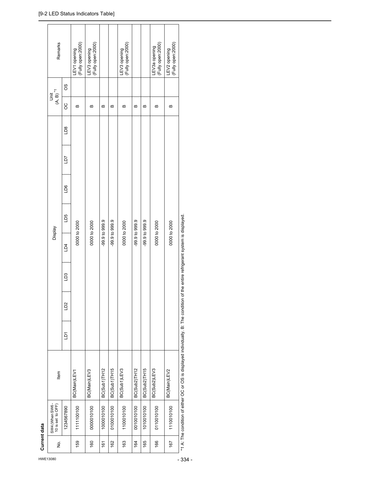
[9-2 LED Status Indicators Table]
Hwe13080
159 1111100100 BC(Main)LEV1 0000 to 2000B
LEV1 opening (Fully open:2000) 160 0000010100 BC(Main)LEV3 0000 to 2000B
LEV3 opening (Fully open:2000) 161 1000010100 BC(Sub1)TH12 -99.9 to 999.9B
162 0100010100 BC(Sub1)TH15 -99.9 to 999.9B
163 1100010100 BC(Sub1)LEV3 0000 to 2000B
LEV3 opening (Fully open:2000) 164 0010010100 BC(Sub2)TH12 -99.9 to 999.9B
165 1010010100 BC(Sub2)TH15 -99.9 to 999.9B
166 0110010100 BC(Sub2)LEV3 0000 to 2000B
LEV3a opening (Fully open:2000) 167 1110010100 BC(Main)LEV2 0000 to 2000B
LEV2 opening (Fully open:2000) Current data No. SW4 (When SW6 - 10 is set to OFF) Item Display Unit(A, B) *1
Remarks 1234567890Ld1
Ld2
Ld3
Ld4
Ld5
Ld6
Ld7
Ld8
Oc
Os
*1 A: The condition of either OC or OS is displayed individually. B: The condition of the entire refrigerant system is displayed.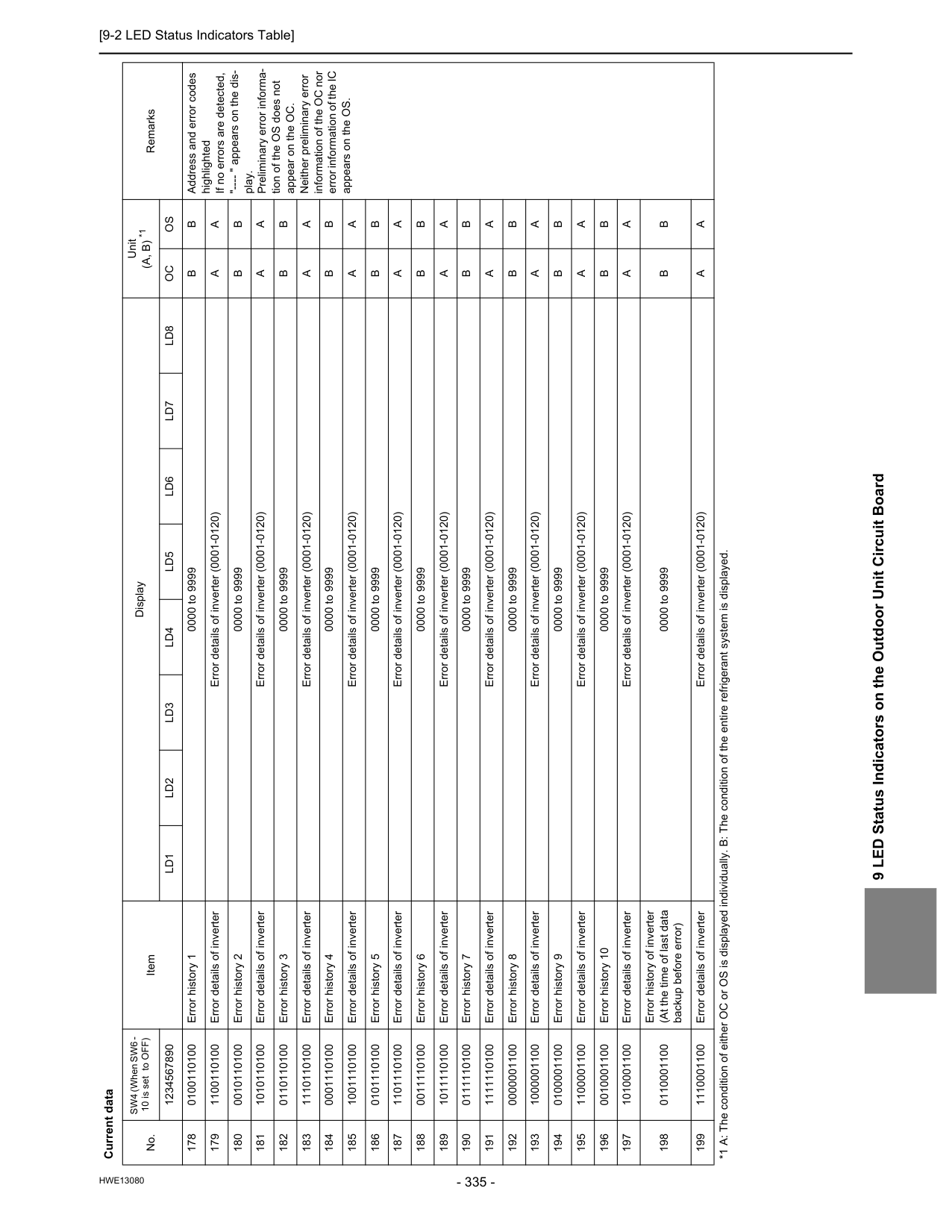
[9-2 LED Status Indicators Table]
Hwe13080
9 LED Status Indicators on the Outdoor Unit Circuit Board 178 0100110100 Error history 1 0000 to 9999B
B
Address and error codes highlighted If no errors are detected, "---- " appears on the dis- play. Preliminary error informa- tion of the OS does not appear on the OC. Neither preliminary error information of the OC nor error information of the IC appears on the OS. 179 1100110100 Error details of inverter Error details of inverter (0001-0120)A
A
180 0010110100 Error history 2 0000 to 9999B
B
181 1010110100 Error details of inverter Error details of inverter (0001-0120)A
A
182 0110110100 Error history 3 0000 to 9999B
B
183 1110110100 Error details of inverter Error details of inverter (0001-0120)A
A
184 0001110100 Error history 4 0000 to 9999B
B
185 1001110100 Error details of inverter Error details of inverter (0001-0120)A
A
186 0101110100 Error history 5 0000 to 9999B
B
187 1101110100 Error details of inverter Error details of inverter (0001-0120)A
A
188 0011110100 Error history 6 0000 to 9999B
B
189 1011110100 Error details of inverter Error details of inverter (0001-0120)A
A
190 0111110100 Error history 7 0000 to 9999B
B
191 1111110100 Error details of inverter Error details of inverter (0001-0120)A
A
192 0000001100 Error history 8 0000 to 9999B
B
193 1000001100 Error details of inverter Error details of inverter (0001-0120)A
A
194 0100001100 Error history 9 0000 to 9999B
B
195 1100001100 Error details of inverter Error details of inverter (0001-0120)A
A
196 0010001100 Error history 10 0000 to 9999B
B
197 1010001100 Error details of inverter Error details of inverter (0001-0120)A
A
198 0110001100 Error history of inverter (At the time of last data backup before error) 0000 to 9999B
B
199 1110001100 Error details of inverter Error details of inverter (0001-0120)A
A
Current data No. SW4 (When SW6 - 10 is set to OFF) Item Display Unit(A, B) *1
Remarks 1234567890Ld1
Ld2
Ld3
Ld4
Ld5
Ld6
Ld7
Ld8
Oc
Os
*1 A: The condition of either OC or OS is displayed individually. B: The condition of the entire refrigerant system is displayed.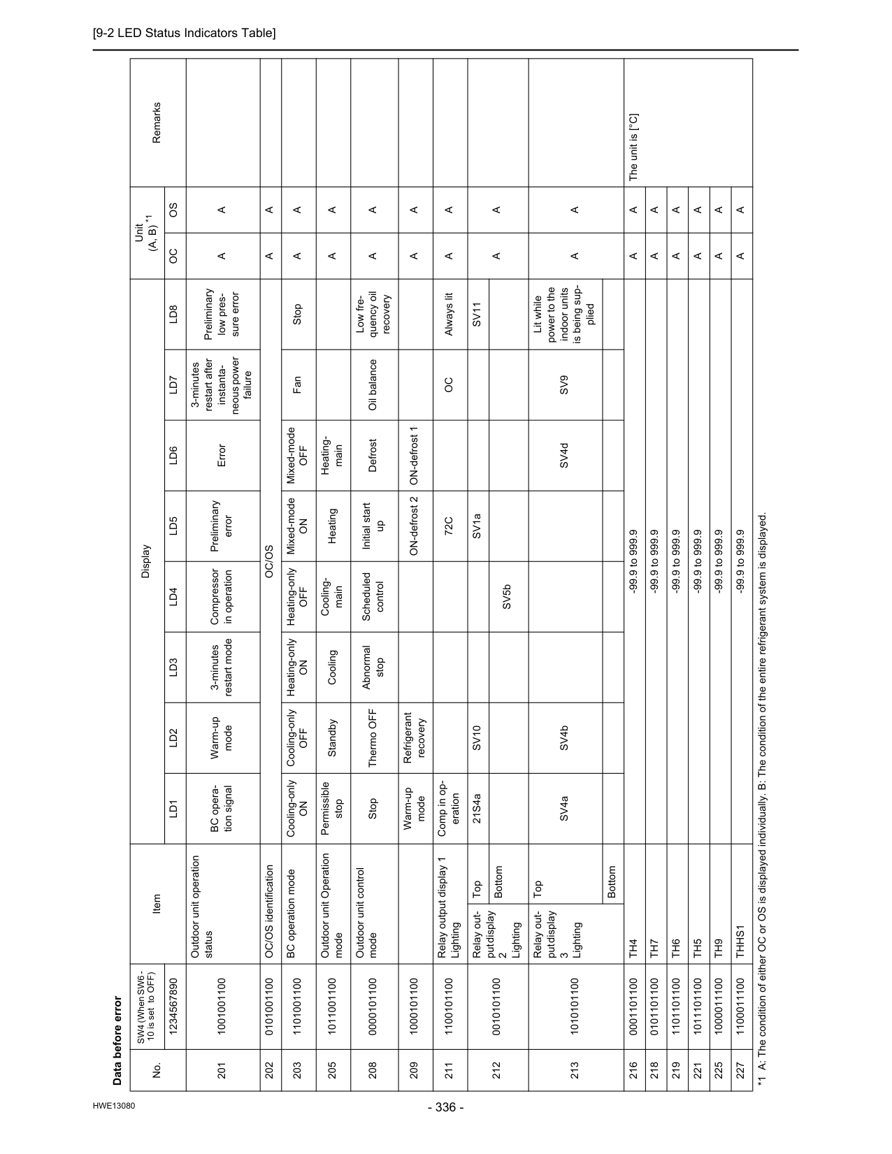
[9-2 LED Status Indicators Table]
Hwe13080
Data before error No. SW4 (When SW6 - 10 is set to OFF) Item Display Unit(A, B) *1
Remarks 1234567890Ld1
Ld2
Ld3
Ld4
Ld5
Ld6
Ld7
Ld8
Oc
Os
201 1001001100 Outdoor unit operation status BC opera- tion signal Warm-up mode 3-minutes restart mode Compressor in operation Preliminary error Error 3-minutes restart after instanta- neous power failure Preliminary low pres- sure errorA
A
202 0101001100 OC/OS identificationOc/Os
A
A
203 1101001100 BC operation mode Cooling-onlyOn
Cooling-onlyOff
Heating-onlyOn
Heating-onlyOff
Mixed-modeOn
Mixed-modeOff
Fan StopA
A
205 1011001100 Outdoor unit Operation mode Permissible stop Standby Cooling Cooling- main Heating Heating- mainA
A
208 0000101100 Outdoor unit control mode Stop Thermo OFF Abnormal stop Scheduled control Initial start up Defrost Oil balance Low fre- quency oil recoveryA
A
209 1000101100 Warm-up mode Refrigerant recovery ON-defrost 2 ON-defrost 1A
A
211 1100101100 Relay output display 1 Lighting Comp in op- eration72C
Oc
Always litA
A
212 0010101100 Relay out- put display 2 Lighting Top 21S4aSv10
SV1aSv11
A
A
Bottom SV5b 213 1010101100 Relay out- put display 3 Lighting Top SV4a SV4b SV4dSv9
Lit while power to the indoor units is being sup- pliedA
A
Bottom 216 0001101100Th4
-99.9 to 999.9A
A
The unit is [°C] 218 0101101100Th7
-99.9 to 999.9A
A
219 1101101100Th6
-99.9 to 999.9A
A
221 1011101100Th5
-99.9 to 999.9A
A
225 1000011100Th9
-99.9 to 999.9A
A
227 1100011100Thhs1
-99.9 to 999.9A
A
*1 A: The condition of either OC or OS is displayed individually. B: The condition of the entire refrigerant system is displayed.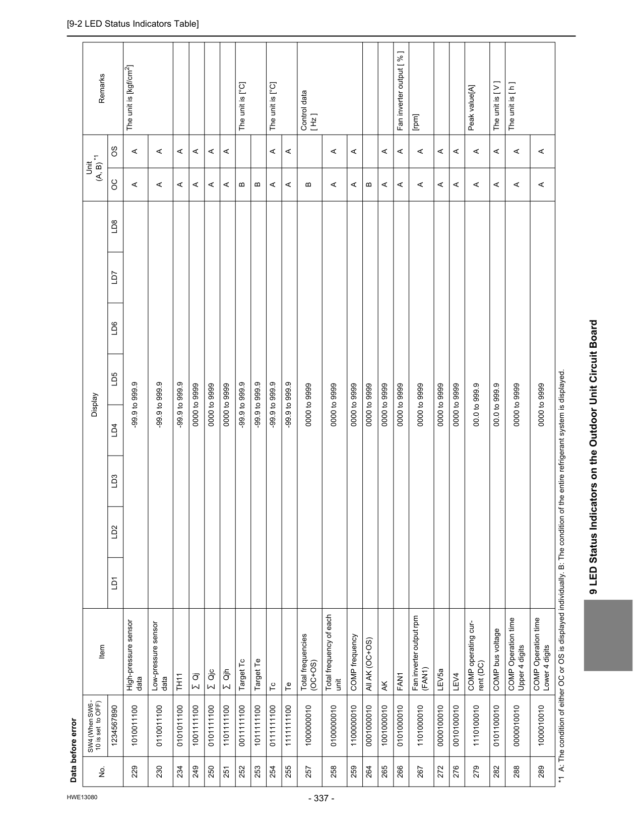
[9-2 LED Status Indicators Table]
Hwe13080
9 LED Status Indicators on the Outdoor Unit Circuit Board 229 1010011100 High-pressure sensor data -99.9 to 999.9A
A
The unit is [kgf/cm2] 230 0110011100 Low-pressure sensor data -99.9 to 999.9A
A
234 0101011100Th11
-99.9 to 999.9A
A
249 1001111100 Qj 0000 to 9999A
A
250 0101111100 Qjc 0000 to 9999A
A
251 1101111100 Qjh 0000 to 9999A
A
252 0011111100 Target Tc -99.9 to 999.9B
The unit is [°C] 253 1011111100 Target Te -99.9 to 999.9B
254 0111111100 Tc -99.9 to 999.9A
A
The unit is [°C] 255 1111111100 Te -99.9 to 999.9A
A
257 1000000010 Total frequencies(Oc+Os)
0000 to 9999B
Control data [ Hz ] 258 0100000010 Total frequency of each unit 0000 to 9999A
A
259 1100000010 COMP frequency 0000 to 9999A
A
264 0001000010 All AK (OC+OS) 0000 to 9999B
265 1001000010Ak
0000 to 9999A
A
266 0101000010Fan1
0000 to 9999A
A
Fan inverter output [ % ] 267 1101000010 Fan inverter output rpm(Fan1)
0000 to 9999A
A
[rpm] 272 0000100010 LEV5a 0000 to 9999A
A
276 0010100010Lev4
0000 to 9999A
A
279 1110100010 COMP operating cur- rent (DC) 00.0 to 999.9A
A
Peak value[A] 282 0101100010 COMP bus voltage 00.0 to 999.9A
A
The unit is [ V ] 288 0000010010 COMP Operation time Upper 4 digits 0000 to 9999A
A
The unit is [ h ] 289 1000010010 COMP Operation time Lower 4 digits 0000 to 9999A
A
Data before error No. SW4 (When SW6 - 10 is set to OFF) Item Display Unit(A, B) *1
Remarks 1234567890Ld1
Ld2
Ld3
Ld4
Ld5
Ld6
Ld7
Ld8
Oc
Os
*1 A: The condition of either OC or OS is displayed individually. B: The condition of the entire refrigerant system is displayed.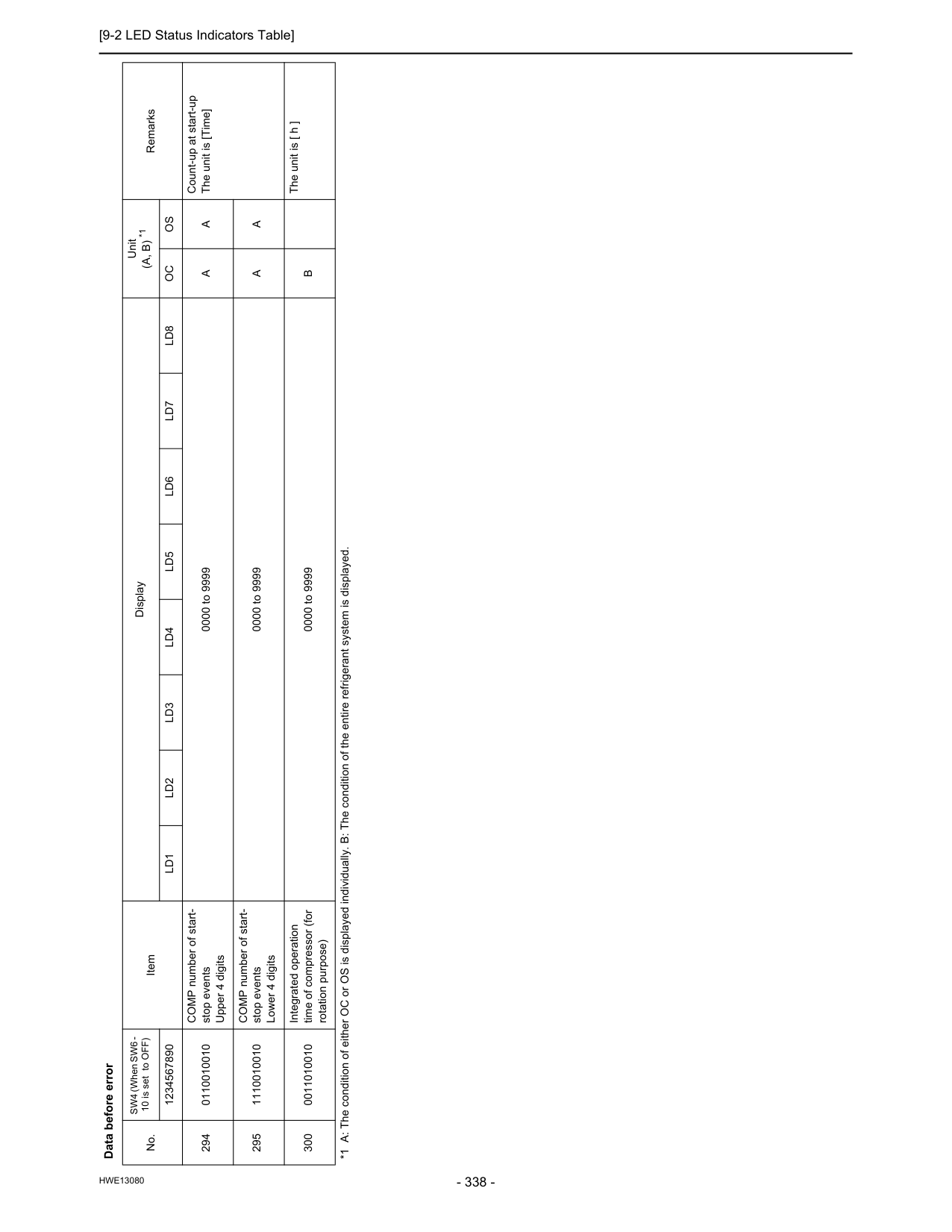
[9-2 LED Status Indicators Table]
Hwe13080
294 0110010010 COMP number of start- stop events Upper 4 digits 0000 to 9999A
A
Count-up at start-up The unit is [Time] 295 1110010010 COMP number of start- stop events Lower 4 digits 0000 to 9999A
A
300 0011010010 Integrated operation time of compressor (for rotation purpose) 0000 to 9999B
The unit is [ h ] Data before error No. SW4 (When SW6 - 10 is set to OFF) Item Display Unit(A, B) *1
Remarks 1234567890Ld1
Ld2
Ld3
Ld4
Ld5
Ld6
Ld7
Ld8
Oc
Os
*1 A: The condition of either OC or OS is displayed individually. B: The condition of the entire refrigerant system is displayed.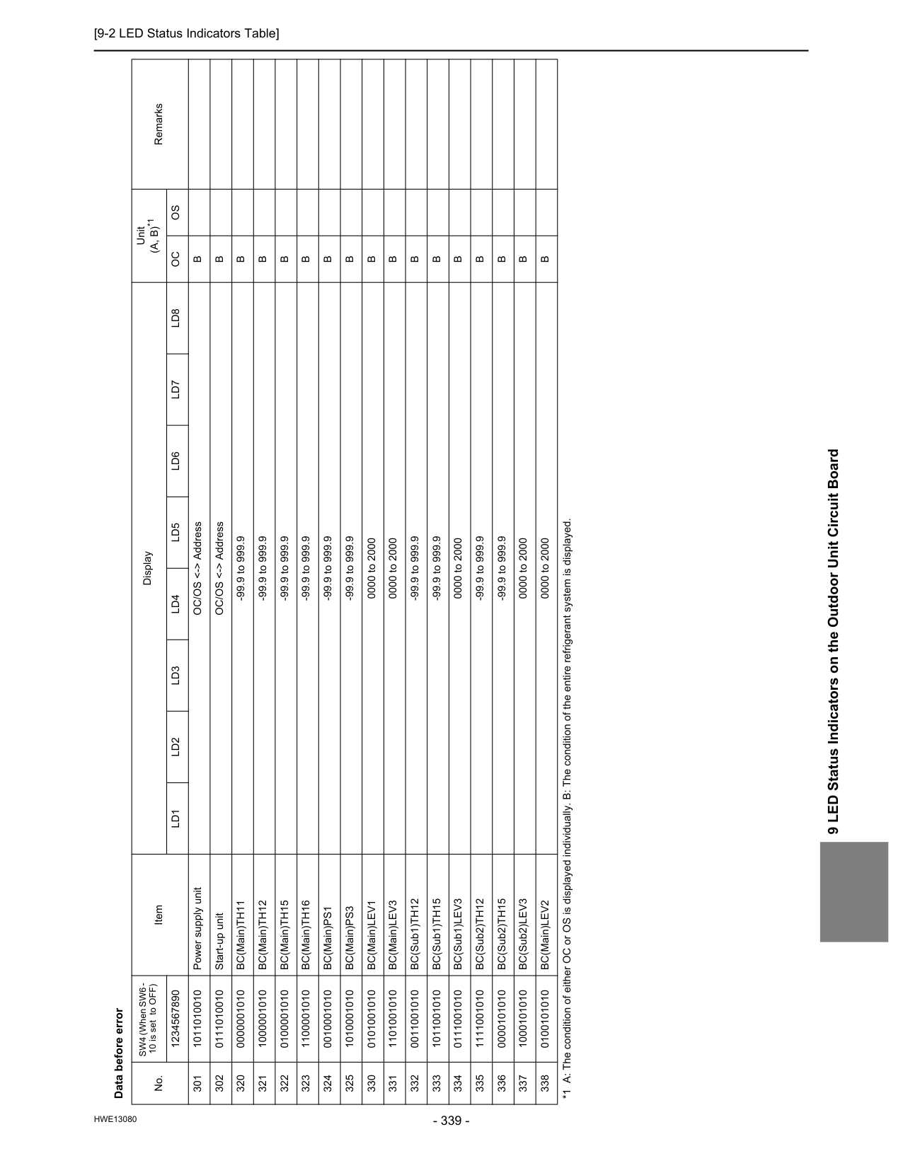
[9-2 LED Status Indicators Table]
Hwe13080
9 LED Status Indicators on the Outdoor Unit Circuit Board Data before error No. SW4 (When SW6 - 10 is set to OFF) Item Display Unit(A, B)*1
Remarks 1234567890Ld1
Ld2
Ld3
Ld4
Ld5
Ld6
Ld7
Ld8
Oc
Os
301 1011010010 Power supply unit OC/OS <-> AddressB
302 0111010010 Start-up unit OC/OS <-> AddressB
320 0000001010 BC(Main)TH11 -99.9 to 999.9B
321 1000001010 BC(Main)TH12 -99.9 to 999.9B
322 0100001010 BC(Main)TH15 -99.9 to 999.9B
323 1100001010 BC(Main)TH16 -99.9 to 999.9B
324 0010001010 BC(Main)PS1 -99.9 to 999.9B
325 1010001010 BC(Main)PS3 -99.9 to 999.9B
330 0101001010 BC(Main)LEV1 0000 to 2000B
331 1101001010 BC(Main)LEV3 0000 to 2000B
332 0011001010 BC(Sub1)TH12 -99.9 to 999.9B
333 1011001010 BC(Sub1)TH15 -99.9 to 999.9B
334 0111001010 BC(Sub1)LEV3 0000 to 2000B
335 1111001010 BC(Sub2)TH12 -99.9 to 999.9B
336 0000101010 BC(Sub2)TH15 -99.9 to 999.9B
337 1000101010 BC(Sub2)LEV3 0000 to 2000B
338 0100101010 BC(Main)LEV2 0000 to 2000B
*1 A: The condition of either OC or OS is displayed individually. B: The condition of the entire refrigerant system is displayed.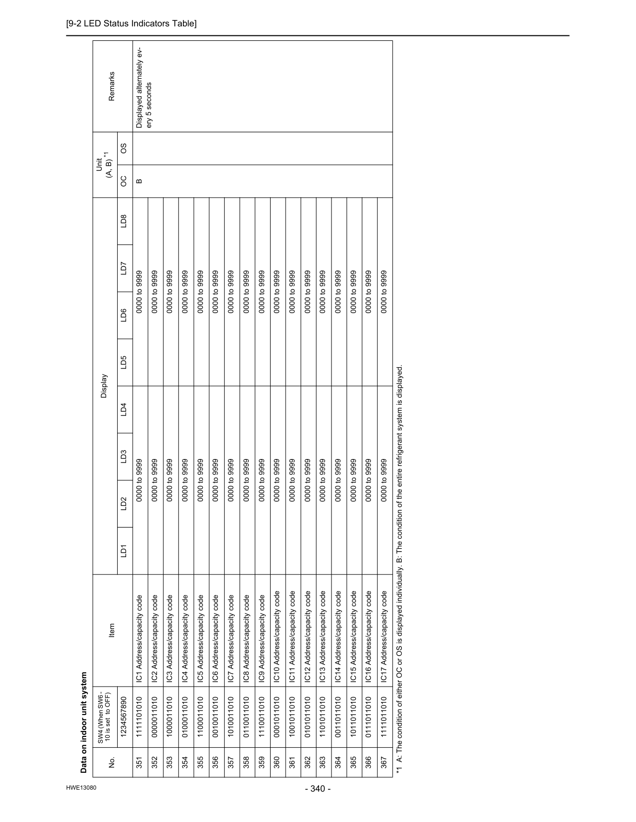
[9-2 LED Status Indicators Table]
Hwe13080
Data on indoor unit system No. SW4 (When SW6 - 10 is set to OFF) Item Display Unit(A, B) *1
Remarks 1234567890Ld1
Ld2
Ld3
Ld4
Ld5
Ld6
Ld7
Ld8
Oc
Os
351 1111101010 IC1 Address/capacity code 0000 to 9999 0000 to 9999B
Displayed alternately ev- ery 5 seconds 352 0000011010 IC2 Address/capacity code 0000 to 9999 0000 to 9999 353 1000011010 IC3 Address/capacity code 0000 to 9999 0000 to 9999 354 0100011010 IC4 Address/capacity code 0000 to 9999 0000 to 9999 355 1100011010 IC5 Address/capacity code 0000 to 9999 0000 to 9999 356 0010011010 IC6 Address/capacity code 0000 to 9999 0000 to 9999 357 1010011010 IC7 Address/capacity code 0000 to 9999 0000 to 9999 358 0110011010 IC8 Address/capacity code 0000 to 9999 0000 to 9999 359 1110011010 IC9 Address/capacity code 0000 to 9999 0000 to 9999 360 0001011010 IC10 Address/capacity code 0000 to 9999 0000 to 9999 361 1001011010 IC11 Address/capacity code 0000 to 9999 0000 to 9999 362 0101011010 IC12 Address/capacity code 0000 to 9999 0000 to 9999 363 1101011010 IC13 Address/capacity code 0000 to 9999 0000 to 9999 364 0011011010 IC14 Address/capacity code 0000 to 9999 0000 to 9999 365 1011011010 IC15 Address/capacity code 0000 to 9999 0000 to 9999 366 0111011010 IC16 Address/capacity code 0000 to 9999 0000 to 9999 367 1111011010 IC17 Address/capacity code 0000 to 9999 0000 to 9999 *1 A: The condition of either OC or OS is displayed individually. B: The condition of the entire refrigerant system is displayed.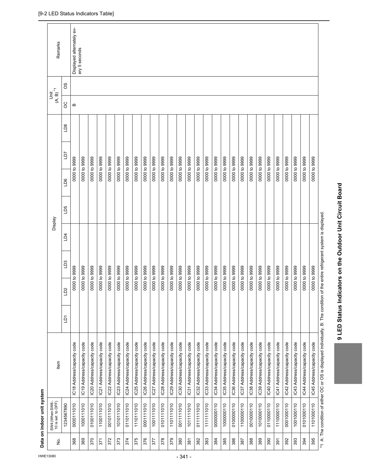
[9-2 LED Status Indicators Table]
Hwe13080
9 LED Status Indicators on the Outdoor Unit Circuit Board 368 0000111010 IC18 Address/capacity code 0000 to 9999 0000 to 9999B
Displayed alternately ev- ery 5 seconds 369 1000111010 IC19 Address/capacity code 0000 to 9999 0000 to 9999 370 0100111010 IC20 Address/capacity code 0000 to 9999 0000 to 9999 371 1100111010 IC21 Address/capacity code 0000 to 9999 0000 to 9999 372 0010111010 IC22 Address/capacity code 0000 to 9999 0000 to 9999 373 1010111010 IC23 Address/capacity code 0000 to 9999 0000 to 9999 374 0110111010 IC24 Address/capacity code 0000 to 9999 0000 to 9999 375 1110111010 IC25 Address/capacity code 0000 to 9999 0000 to 9999 376 0001111010 IC26 Address/capacity code 0000 to 9999 0000 to 9999 377 1001111010 IC27 Address/capacity code 0000 to 9999 0000 to 9999 378 0101111010 IC28 Address/capacity code 0000 to 9999 0000 to 9999 379 1101111010 IC29 Address/capacity code 0000 to 9999 0000 to 9999 380 0011111010 IC30 Address/capacity code 0000 to 9999 0000 to 9999 381 1011111010 IC31 Address/capacity code 0000 to 9999 0000 to 9999 382 0111111010 IC32 Address/capacity code 0000 to 9999 0000 to 9999 383 1111111010 IC33 Address/capacity code 0000 to 9999 0000 to 9999 384 0000000110 IC34 Address/capacity code 0000 to 9999 0000 to 9999 385 1000000110 IC35 Address/capacity code 0000 to 9999 0000 to 9999 386 0100000110 IC36 Address/capacity code 0000 to 9999 0000 to 9999 387 1100000110 IC37 Address/capacity code 0000 to 9999 0000 to 9999 388 0010000110 IC38 Address/capacity code 0000 to 9999 0000 to 9999 389 1010000110 IC39 Address/capacity code 0000 to 9999 0000 to 9999 390 0110000110 IC40 Address/capacity code 0000 to 9999 0000 to 9999 391 1110000110 IC41 Address/capacity code 0000 to 9999 0000 to 9999 392 0001000110 IC42 Address/capacity code 0000 to 9999 0000 to 9999 393 1001000110 IC43 Address/capacity code 0000 to 9999 0000 to 9999 394 0101000110 IC44 Address/capacity code 0000 to 9999 0000 to 9999 395 1101000110 IC45 Address/capacity code 0000 to 9999 0000 to 9999 Data on indoor unit system No. SW4 (When SW6 - 10 is set to OFF) Item Display Unit(A, B) *1
Remarks 1234567890Ld1
Ld2
Ld3
Ld4
Ld5
Ld6
Ld7
Ld8
Oc
Os
*1 A: The condition of either OC or OS is displayed individually. B: The condition of the entire refrigerant system is displayed.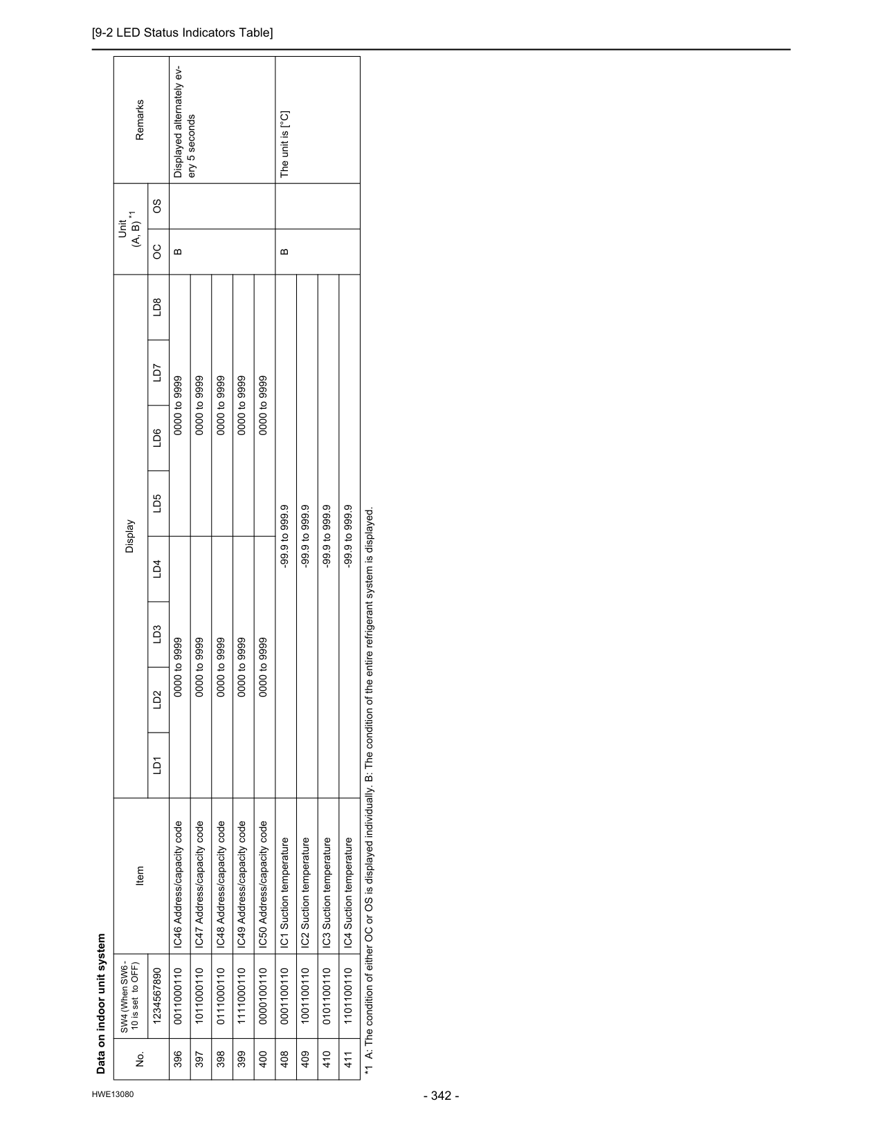
[9-2 LED Status Indicators Table]
Hwe13080
396 0011000110 IC46 Address/capacity code 0000 to 9999 0000 to 9999B
Displayed alternately ev- ery 5 seconds 397 1011000110 IC47 Address/capacity code 0000 to 9999 0000 to 9999 398 0111000110 IC48 Address/capacity code 0000 to 9999 0000 to 9999 399 1111000110 IC49 Address/capacity code 0000 to 9999 0000 to 9999 400 0000100110 IC50 Address/capacity code 0000 to 9999 0000 to 9999 408 0001100110 IC1 Suction temperature -99.9 to 999.9B
The unit is [°C] 409 1001100110 IC2 Suction temperature -99.9 to 999.9 410 0101100110 IC3 Suction temperature -99.9 to 999.9 411 1101100110 IC4 Suction temperature -99.9 to 999.9 Data on indoor unit system No. SW4 (When SW6 - 10 is set to OFF) Item Display Unit(A, B) *1
Remarks 1234567890Ld1
Ld2
Ld3
Ld4
Ld5
Ld6
Ld7
Ld8
Oc
Os
*1 A: The condition of either OC or OS is displayed individually. B: The condition of the entire refrigerant system is displayed.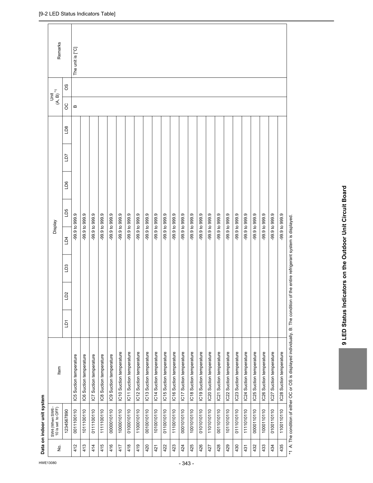
[9-2 LED Status Indicators Table]
Hwe13080
9 LED Status Indicators on the Outdoor Unit Circuit Board 412 0011100110 IC5 Suction temperature -99.9 to 999.9B
The unit is [°C] 413 1011100110 IC6 Suction temperature -99.9 to 999.9 414 0111100110 IC7 Suction temperature -99.9 to 999.9 415 1111100110 IC8 Suction temperature -99.9 to 999.9 416 0000010110 IC9 Suction temperature -99.9 to 999.9 417 1000010110 IC10 Suction temperature -99.9 to 999.9 418 0100010110 IC11 Suction temperature -99.9 to 999.9 419 1100010110 IC12 Suction temperature -99.9 to 999.9 420 0010010110 IC13 Suction temperature -99.9 to 999.9 421 1010010110 IC14 Suction temperature -99.9 to 999.9 422 0110010110 IC15 Suction temperature -99.9 to 999.9 423 1110010110 IC16 Suction temperature -99.9 to 999.9 424 0001010110 IC17 Suction temperature -99.9 to 999.9 425 1001010110 IC18 Suction temperature -99.9 to 999.9 426 0101010110 IC19 Suction temperature -99.9 to 999.9 427 1101010110 IC20 Suction temperature -99.9 to 999.9 428 0011010110 IC21 Suction temperature -99.9 to 999.9 429 1011010110 IC22 Suction temperature -99.9 to 999.9 430 0111010110 IC23 Suction temperature -99.9 to 999.9 431 1111010110 IC24 Suction temperature -99.9 to 999.9 432 0000110110 IC25 Suction temperature -99.9 to 999.9 433 1000110110 IC26 Suction temperature -99.9 to 999.9 434 0100110110 IC27 Suction temperature -99.9 to 999.9 435 1100110110 IC28 Suction temperature -99.9 to 999.9 Data on indoor unit system No. SW4 (When SW6 - 10 is set to OFF) Item Display Unit(A, B) *1
Remarks 1234567890Ld1
Ld2
Ld3
Ld4
Ld5
Ld6
Ld7
Ld8
Oc
Os
*1 A: The condition of either OC or OS is displayed individually. B: The condition of the entire refrigerant system is displayed.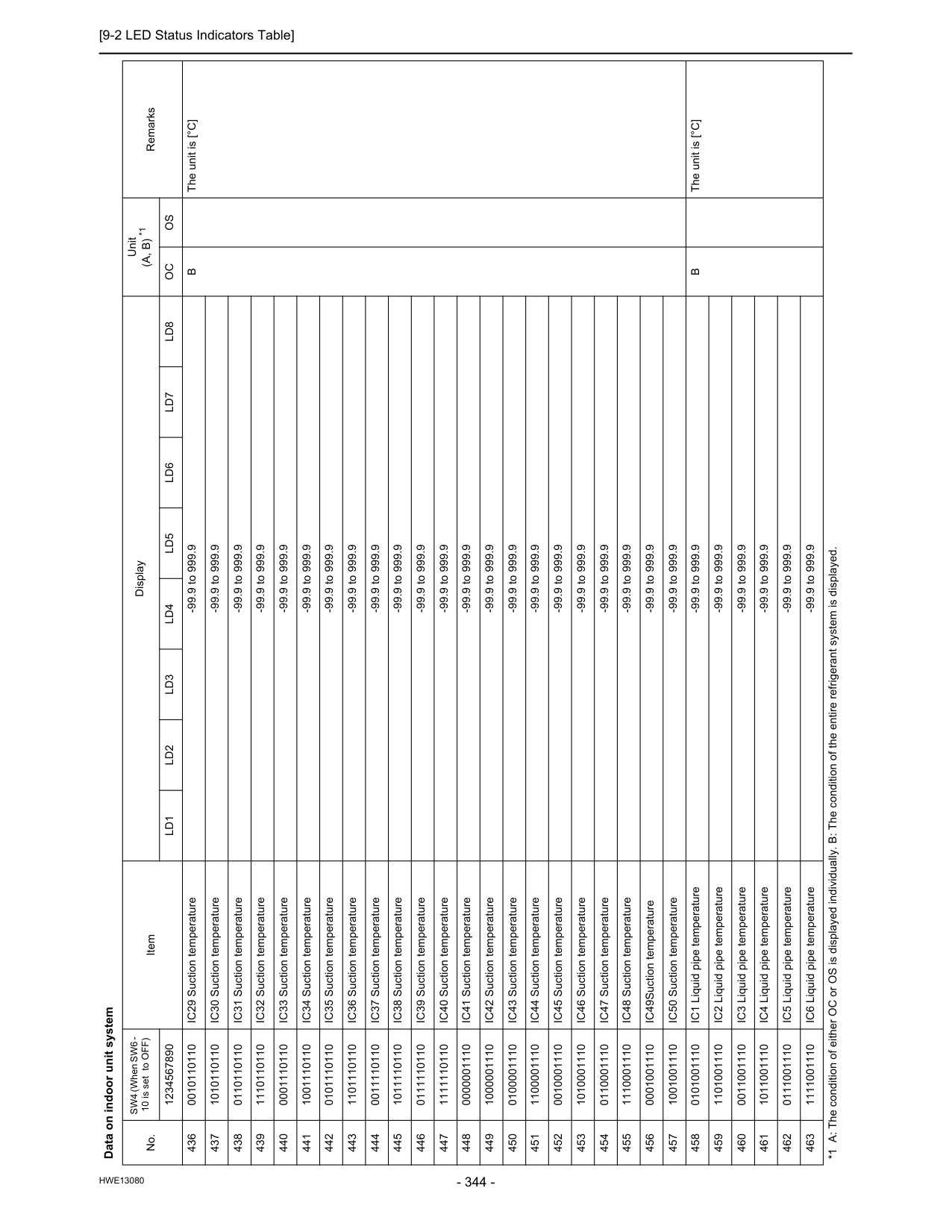
[9-2 LED Status Indicators Table]
Hwe13080
436 0010110110 IC29 Suction temperature -99.9 to 999.9B
The unit is [°C] 437 1010110110 IC30 Suction temperature -99.9 to 999.9 438 0110110110 IC31 Suction temperature -99.9 to 999.9 439 1110110110 IC32 Suction temperature -99.9 to 999.9 440 0001110110 IC33 Suction temperature -99.9 to 999.9 441 1001110110 IC34 Suction temperature -99.9 to 999.9 442 0101110110 IC35 Suction temperature -99.9 to 999.9 443 1101110110 IC36 Suction temperature -99.9 to 999.9 444 0011110110 IC37 Suction temperature -99.9 to 999.9 445 1011110110 IC38 Suction temperature -99.9 to 999.9 446 0111110110 IC39 Suction temperature -99.9 to 999.9 447 1111110110 IC40 Suction temperature -99.9 to 999.9 448 0000001110 IC41 Suction temperature -99.9 to 999.9 449 1000001110 IC42 Suction temperature -99.9 to 999.9 450 0100001110 IC43 Suction temperature -99.9 to 999.9 451 1100001110 IC44 Suction temperature -99.9 to 999.9 452 0010001110 IC45 Suction temperature -99.9 to 999.9 453 1010001110 IC46 Suction temperature -99.9 to 999.9 454 0110001110 IC47 Suction temperature -99.9 to 999.9 455 1110001110 IC48 Suction temperature -99.9 to 999.9 456 0001001110 IC49Suction temperature -99.9 to 999.9 457 1001001110 IC50 Suction temperature -99.9 to 999.9 458 0101001110 IC1 Liquid pipe temperature -99.9 to 999.9B
The unit is [°C] 459 1101001110 IC2 Liquid pipe temperature -99.9 to 999.9 460 0011001110 IC3 Liquid pipe temperature -99.9 to 999.9 461 1011001110 IC4 Liquid pipe temperature -99.9 to 999.9 462 0111001110 IC5 Liquid pipe temperature -99.9 to 999.9 463 1111001110 IC6 Liquid pipe temperature -99.9 to 999.9 Data on indoor unit system No. SW4 (When SW6 - 10 is set to OFF) Item Display Unit(A, B) *1
Remarks 1234567890Ld1
Ld2
Ld3
Ld4
Ld5
Ld6
Ld7
Ld8
Oc
Os
*1 A: The condition of either OC or OS is displayed individually. B: The condition of the entire refrigerant system is displayed.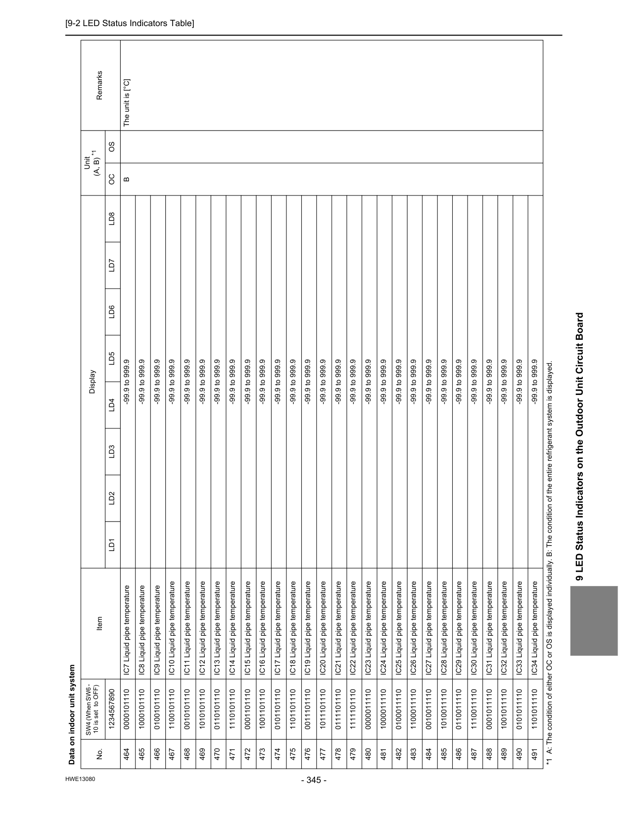
[9-2 LED Status Indicators Table]
Hwe13080
9 LED Status Indicators on the Outdoor Unit Circuit Board 464 0000101110 IC7 Liquid pipe temperature -99.9 to 999.9B
The unit is [°C] 465 1000101110 IC8 Liquid pipe temperature -99.9 to 999.9 466 0100101110 IC9 Liquid pipe temperature -99.9 to 999.9 467 1100101110 IC10 Liquid pipe temperature -99.9 to 999.9 468 0010101110 IC11 Liquid pipe temperature -99.9 to 999.9 469 1010101110 IC12 Liquid pipe temperature -99.9 to 999.9 470 0110101110 IC13 Liquid pipe temperature -99.9 to 999.9 471 1110101110 IC14 Liquid pipe temperature -99.9 to 999.9 472 0001101110 IC15 Liquid pipe temperature -99.9 to 999.9 473 1001101110 IC16 Liquid pipe temperature -99.9 to 999.9 474 0101101110 IC17 Liquid pipe temperature -99.9 to 999.9 475 1101101110 IC18 Liquid pipe temperature -99.9 to 999.9 476 0011101110 IC19 Liquid pipe temperature -99.9 to 999.9 477 1011101110 IC20 Liquid pipe temperature -99.9 to 999.9 478 0111101110 IC21 Liquid pipe temperature -99.9 to 999.9 479 1111101110 IC22 Liquid pipe temperature -99.9 to 999.9 480 0000011110 IC23 Liquid pipe temperature -99.9 to 999.9 481 1000011110 IC24 Liquid pipe temperature -99.9 to 999.9 482 0100011110 IC25 Liquid pipe temperature -99.9 to 999.9 483 1100011110 IC26 Liquid pipe temperature -99.9 to 999.9 484 0010011110 IC27 Liquid pipe temperature -99.9 to 999.9 485 1010011110 IC28 Liquid pipe temperature -99.9 to 999.9 486 0110011110 IC29 Liquid pipe temperature -99.9 to 999.9 487 1110011110 IC30 Liquid pipe temperature -99.9 to 999.9 488 0001011110 IC31 Liquid pipe temperature -99.9 to 999.9 489 1001011110 IC32 Liquid pipe temperature -99.9 to 999.9 490 0101011110 IC33 Liquid pipe temperature -99.9 to 999.9 491 1101011110 IC34 Liquid pipe temperature -99.9 to 999.9 Data on indoor unit system No. SW4 (When SW6 - 10 is set to OFF) Item Display Unit(A, B) *1
Remarks 1234567890Ld1
Ld2
Ld3
Ld4
Ld5
Ld6
Ld7
Ld8
Oc
Os
*1 A: The condition of either OC or OS is displayed individually. B: The condition of the entire refrigerant system is displayed.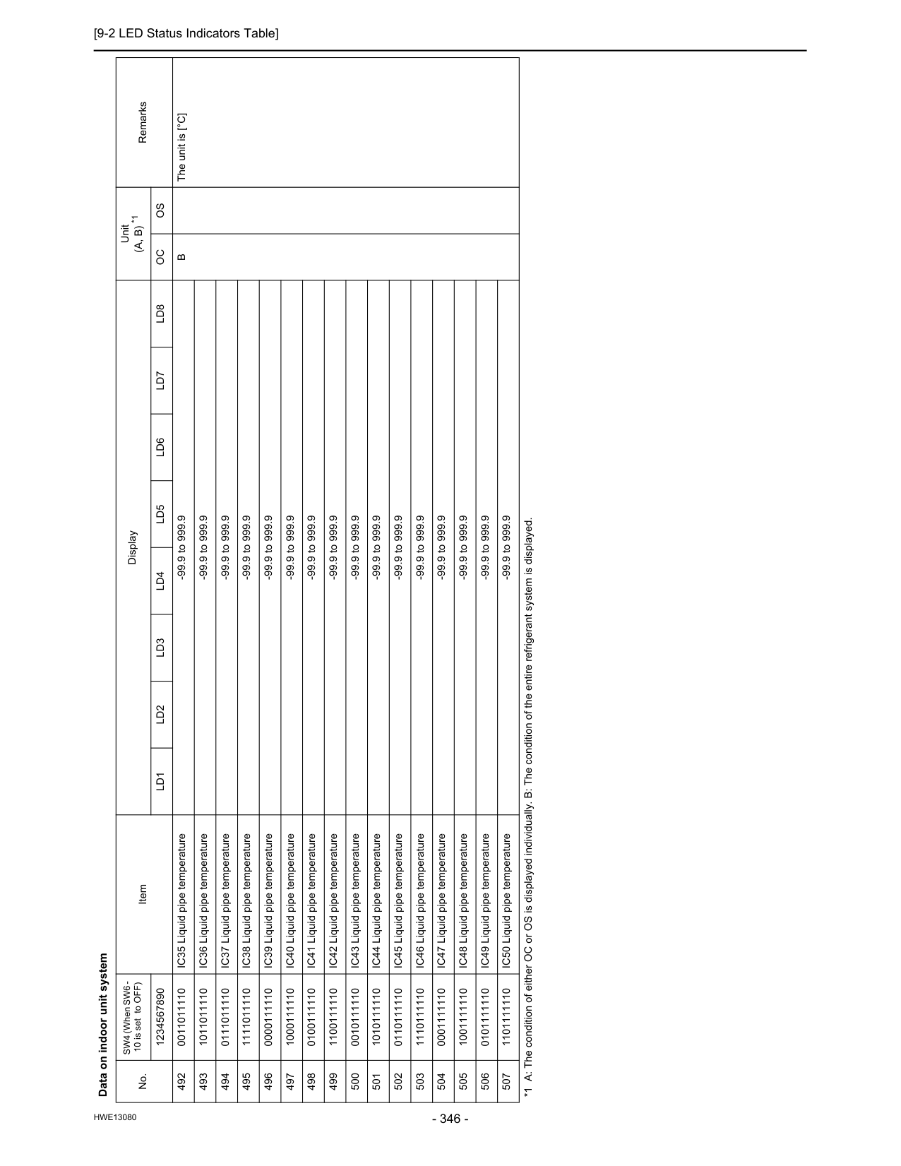
[9-2 LED Status Indicators Table]
Hwe13080
492 0011011110 IC35 Liquid pipe temperature -99.9 to 999.9B
The unit is [°C] 493 1011011110 IC36 Liquid pipe temperature -99.9 to 999.9 494 0111011110 IC37 Liquid pipe temperature -99.9 to 999.9 495 1111011110 IC38 Liquid pipe temperature -99.9 to 999.9 496 0000111110 IC39 Liquid pipe temperature -99.9 to 999.9 497 1000111110 IC40 Liquid pipe temperature -99.9 to 999.9 498 0100111110 IC41 Liquid pipe temperature -99.9 to 999.9 499 1100111110 IC42 Liquid pipe temperature -99.9 to 999.9 500 0010111110 IC43 Liquid pipe temperature -99.9 to 999.9 501 1010111110 IC44 Liquid pipe temperature -99.9 to 999.9 502 0110111110 IC45 Liquid pipe temperature -99.9 to 999.9 503 1110111110 IC46 Liquid pipe temperature -99.9 to 999.9 504 0001111110 IC47 Liquid pipe temperature -99.9 to 999.9 505 1001111110 IC48 Liquid pipe temperature -99.9 to 999.9 506 0101111110 IC49 Liquid pipe temperature -99.9 to 999.9 507 1101111110 IC50 Liquid pipe temperature -99.9 to 999.9 Data on indoor unit system No. SW4 (When SW6 - 10 is set to OFF) Item Display Unit(A, B) *1
Remarks 1234567890Ld1
Ld2
Ld3
Ld4
Ld5
Ld6
Ld7
Ld8
Oc
Os
*1 A: The condition of either OC or OS is displayed individually. B: The condition of the entire refrigerant system is displayed.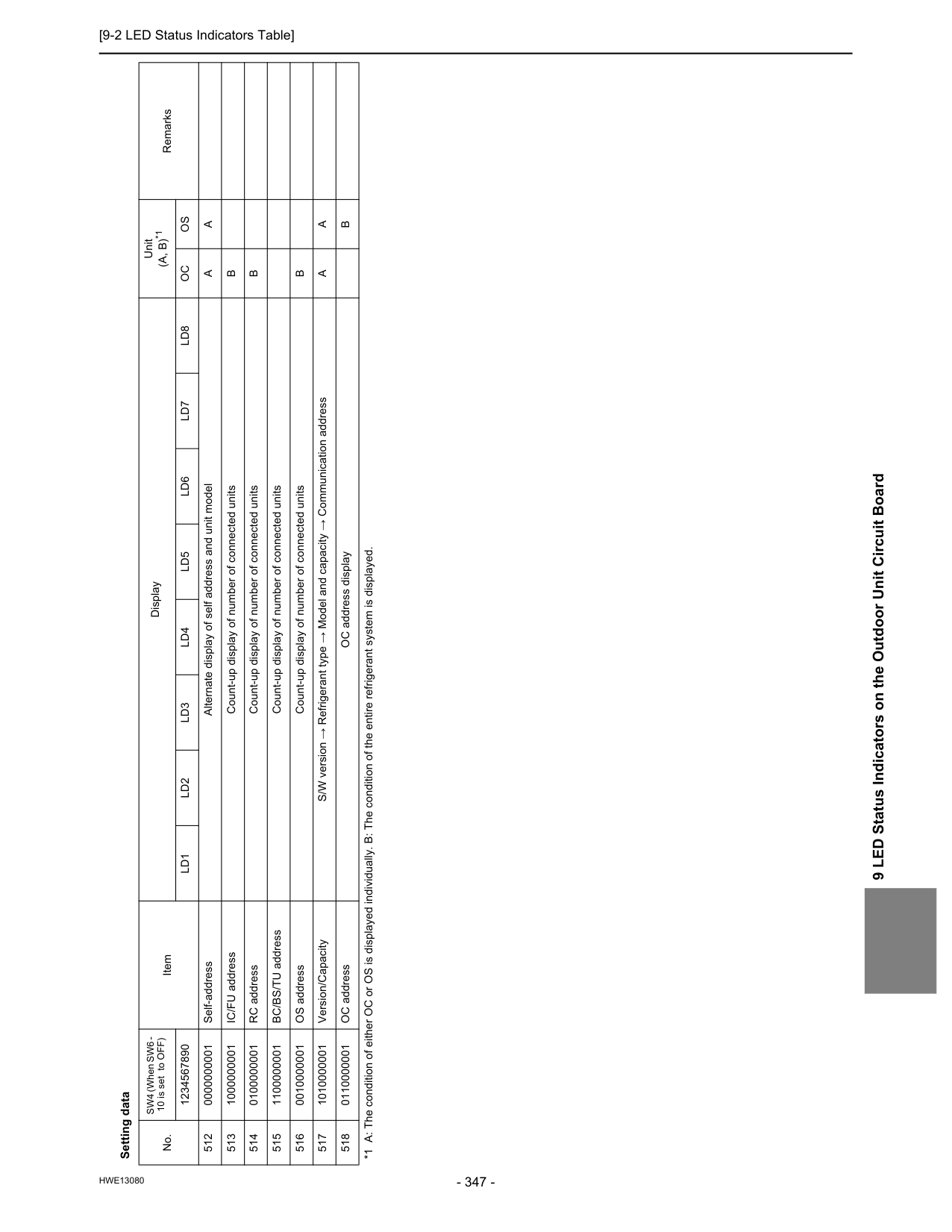
[9-2 LED Status Indicators Table]
Hwe13080
9 LED Status Indicators on the Outdoor Unit Circuit Board Setting data No. SW4 (When SW6 - 10 is set to OFF) Item Display Unit(A, B)*1
Remarks 1234567890Ld1
Ld2
Ld3
Ld4
Ld5
Ld6
Ld7
Ld8
Oc
Os
512 0000000001 Self-address Alternate display of self address and unit modelA
A
513 1000000001 IC/FU address Count-up display of number of connected unitsB
514 0100000001 RC address Count-up display of number of connected unitsB
515 1100000001 BC/BS/TU address Count-up display of number of connected units 516 0010000001 OS address Count-up display of number of connected unitsB
517 1010000001 Version/Capacity S/W version → Refrigerant type → Model and capacity → Communication addressA
A
518 0110000001 OC address OC address displayB
*1 A: The condition of either OC or OS is displayed individually. B: The condition of the entire refrigerant system is displayed.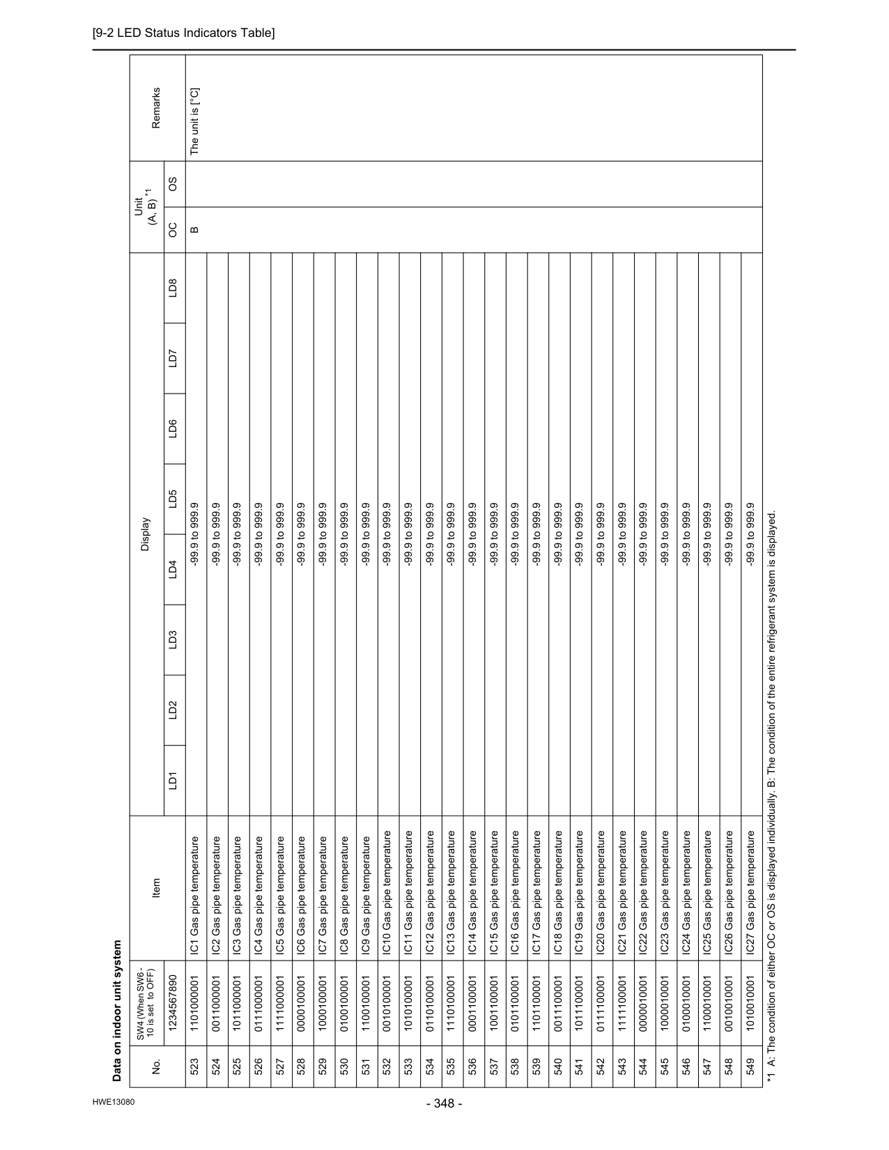
[9-2 LED Status Indicators Table]
Hwe13080
Data on indoor unit system No. SW4 (When SW6 - 10 is set to OFF) Item Display Unit(A, B) *1
Remarks 1234567890Ld1
Ld2
Ld3
Ld4
Ld5
Ld6
Ld7
Ld8
Oc
Os
523 1101000001 IC1 Gas pipe temperature -99.9 to 999.9B
The unit is [°C] 524 0011000001 IC2 Gas pipe temperature -99.9 to 999.9 525 1011000001 IC3 Gas pipe temperature -99.9 to 999.9 526 0111000001 IC4 Gas pipe temperature -99.9 to 999.9 527 1111000001 IC5 Gas pipe temperature -99.9 to 999.9 528 0000100001 IC6 Gas pipe temperature -99.9 to 999.9 529 1000100001 IC7 Gas pipe temperature -99.9 to 999.9 530 0100100001 IC8 Gas pipe temperature -99.9 to 999.9 531 1100100001 IC9 Gas pipe temperature -99.9 to 999.9 532 0010100001 IC10 Gas pipe temperature -99.9 to 999.9 533 1010100001 IC11 Gas pipe temperature -99.9 to 999.9 534 0110100001 IC12 Gas pipe temperature -99.9 to 999.9 535 1110100001 IC13 Gas pipe temperature -99.9 to 999.9 536 0001100001 IC14 Gas pipe temperature -99.9 to 999.9 537 1001100001 IC15 Gas pipe temperature -99.9 to 999.9 538 0101100001 IC16 Gas pipe temperature -99.9 to 999.9 539 1101100001 IC17 Gas pipe temperature -99.9 to 999.9 540 0011100001 IC18 Gas pipe temperature -99.9 to 999.9 541 1011100001 IC19 Gas pipe temperature -99.9 to 999.9 542 0111100001 IC20 Gas pipe temperature -99.9 to 999.9 543 1111100001 IC21 Gas pipe temperature -99.9 to 999.9 544 0000010001 IC22 Gas pipe temperature -99.9 to 999.9 545 1000010001 IC23 Gas pipe temperature -99.9 to 999.9 546 0100010001 IC24 Gas pipe temperature -99.9 to 999.9 547 1100010001 IC25 Gas pipe temperature -99.9 to 999.9 548 0010010001 IC26 Gas pipe temperature -99.9 to 999.9 549 1010010001 IC27 Gas pipe temperature -99.9 to 999.9 *1 A: The condition of either OC or OS is displayed individually. B: The condition of the entire refrigerant system is displayed.
[9-2 LED Status Indicators Table]
Hwe13080
9 LED Status Indicators on the Outdoor Unit Circuit Board Data on indoor unit system No. SW4 (When SW6 - 10 is set to OFF) Item Display Unit(A, B) *1
Remarks 1234567890Ld1
Ld2
Ld3
Ld4
Ld5
Ld6
Ld7
Ld8
Oc
Os
550 0110010001 IC28Gas pipe temperature -99.9 to 999.9B
The unit is [°C] 551 1110010001 IC29 Gas pipe temperature -99.9 to 999.9 552 0001010001 IC30 Gas pipe temperature -99.9 to 999.9 553 1001010001 IC31 Gas pipe temperature -99.9 to 999.9 554 0101010001 IC32 Gas pipe temperature -99.9 to 999.9 555 1101010001 IC33 Gas pipe temperature -99.9 to 999.9 556 0011010001 IC34 Gas pipe temperature -99.9 to 999.9 557 1011010001 IC35 Gas pipe temperature -99.9 to 999.9 558 0111010001 IC36 Gas pipe temperature -99.9 to 999.9 559 1111010001 IC37 Gas pipe temperature -99.9 to 999.9 560 0000110001 IC38 Gas pipe temperature -99.9 to 999.9 561 1000110001 IC39 Gas pipe temperature -99.9 to 999.9 562 0100110001 IC40 Gas pipe temperature -99.9 to 999.9 563 1100110001 IC41 Gas pipe temperature -99.9 to 999.9 564 0010110001 IC42 Gas pipe temperature -99.9 to 999.9 565 1010110001 IC43 Gas pipe temperature -99.9 to 999.9 566 0110110001 IC44 Gas pipe temperature -99.9 to 999.9 567 1110110001 IC45 Gas pipe temperature -99.9 to 999.9 568 0001110001 IC46 Gas pipe temperature -99.9 to 999.9 569 1001110001 IC47 Gas pipe temperature -99.9 to 999.9 570 0101110001 IC48 Gas pipe temperature -99.9 to 999.9 571 1101110001 IC49 Gas pipe temperature -99.9 to 999.9 572 0011110001 IC50 Gas pipe temperature -99.9 to 999.9 *1 A: The condition of either OC or OS is displayed individually. B: The condition of the entire refrigerant system is displayed.
[9-2 LED Status Indicators Table]
Hwe13080
Data on indoor unit system No. SW4 (When SW6 - 10 is set to OFF) Item Display Unit(A, B)*1
Remarks 1234567890Ld1
Ld2
Ld3
Ld4
Ld5
Ld6
Ld7
Ld8
Oc
Os
573 1011110001Ic1Sh
-99.9 to 999.9B
The unit is [ °C ] 574 0111110001Ic2Sh
-99.9 to 999.9 575 1111110001Ic3Sh
-99.9 to 999.9 576 0000001001Ic4Sh
-99.9 to 999.9 577 1000001001Ic5Sh
-99.9 to 999.9 578 0100001001Ic6Sh
-99.9 to 999.9 579 1100001001Ic7Sh
-99.9 to 999.9 580 0010001001Ic8Sh
-99.9 to 999.9 581 1010001001Ic9Sh
-99.9 to 999.9 582 0110001001Ic10Sh
-99.9 to 999.9 583 1110001001Ic11Sh
-99.9 to 999.9 584 0001001001Ic12Sh
-99.9 to 999.9 585 1001001001Ic13Sh
-99.9 to 999.9 586 0101001001Ic14Sh
-99.9 to 999.9 587 1101001001Ic15Sh
-99.9 to 999.9 588 0011001001Ic16Sh
-99.9 to 999.9 589 1011001001Ic17Sh
-99.9 to 999.9 590 0111001001Ic18Sh
-99.9 to 999.9 591 1111001001Ic19Sh
-99.9 to 999.9 592 0000101001Ic20Sh
-99.9 to 999.9 593 1000101001Ic21Sh
-99.9 to 999.9 594 0100101001Ic22Sh
-99.9 to 999.9 595 1100101001Ic23Sh
-99.9 to 999.9 596 0010101001Ic24Sh
-99.9 to 999.9 597 1010101001Ic25Sh
-99.9 to 999.9 598 0110101001Ic26Sh
-99.9 to 999.9 599 1110101001Ic27Sh
-99.9 to 999.9 *1 A: The condition of either OC or OS is displayed individually. B: The condition of the entire refrigerant system is displayed.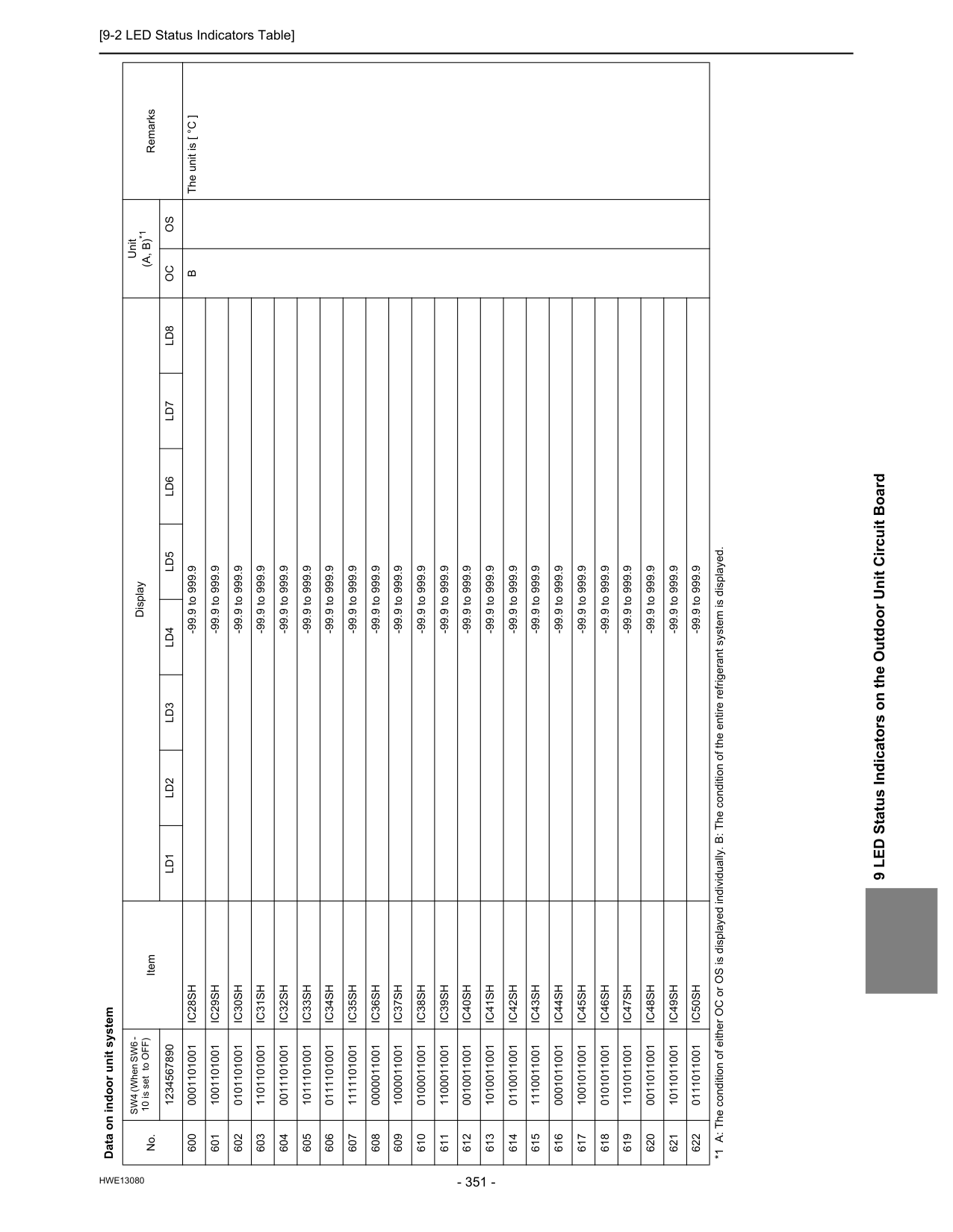
[9-2 LED Status Indicators Table]
Hwe13080
9 LED Status Indicators on the Outdoor Unit Circuit Board 600 0001101001Ic28Sh
-99.9 to 999.9B
The unit is [ °C ] 601 1001101001Ic29Sh
-99.9 to 999.9 602 0101101001Ic30Sh
-99.9 to 999.9 603 1101101001Ic31Sh
-99.9 to 999.9 604 0011101001Ic32Sh
-99.9 to 999.9 605 1011101001Ic33Sh
-99.9 to 999.9 606 0111101001Ic34Sh
-99.9 to 999.9 607 1111101001Ic35Sh
-99.9 to 999.9 608 0000011001Ic36Sh
-99.9 to 999.9 609 1000011001Ic37Sh
-99.9 to 999.9 610 0100011001Ic38Sh
-99.9 to 999.9 611 1100011001Ic39Sh
-99.9 to 999.9 612 0010011001Ic40Sh
-99.9 to 999.9 613 1010011001Ic41Sh
-99.9 to 999.9 614 0110011001Ic42Sh
-99.9 to 999.9 615 1110011001Ic43Sh
-99.9 to 999.9 616 0001011001Ic44Sh
-99.9 to 999.9 617 1001011001Ic45Sh
-99.9 to 999.9 618 0101011001Ic46Sh
-99.9 to 999.9 619 1101011001Ic47Sh
-99.9 to 999.9 620 0011011001Ic48Sh
-99.9 to 999.9 621 1011011001Ic49Sh
-99.9 to 999.9 622 0111011001Ic50Sh
-99.9 to 999.9 Data on indoor unit system No. SW4 (When SW6 - 10 is set to OFF) Item Display Unit(A, B)*1
Remarks 1234567890Ld1
Ld2
Ld3
Ld4
Ld5
Ld6
Ld7
Ld8
Oc
Os
*1 A: The condition of either OC or OS is displayed individually. B: The condition of the entire refrigerant system is displayed.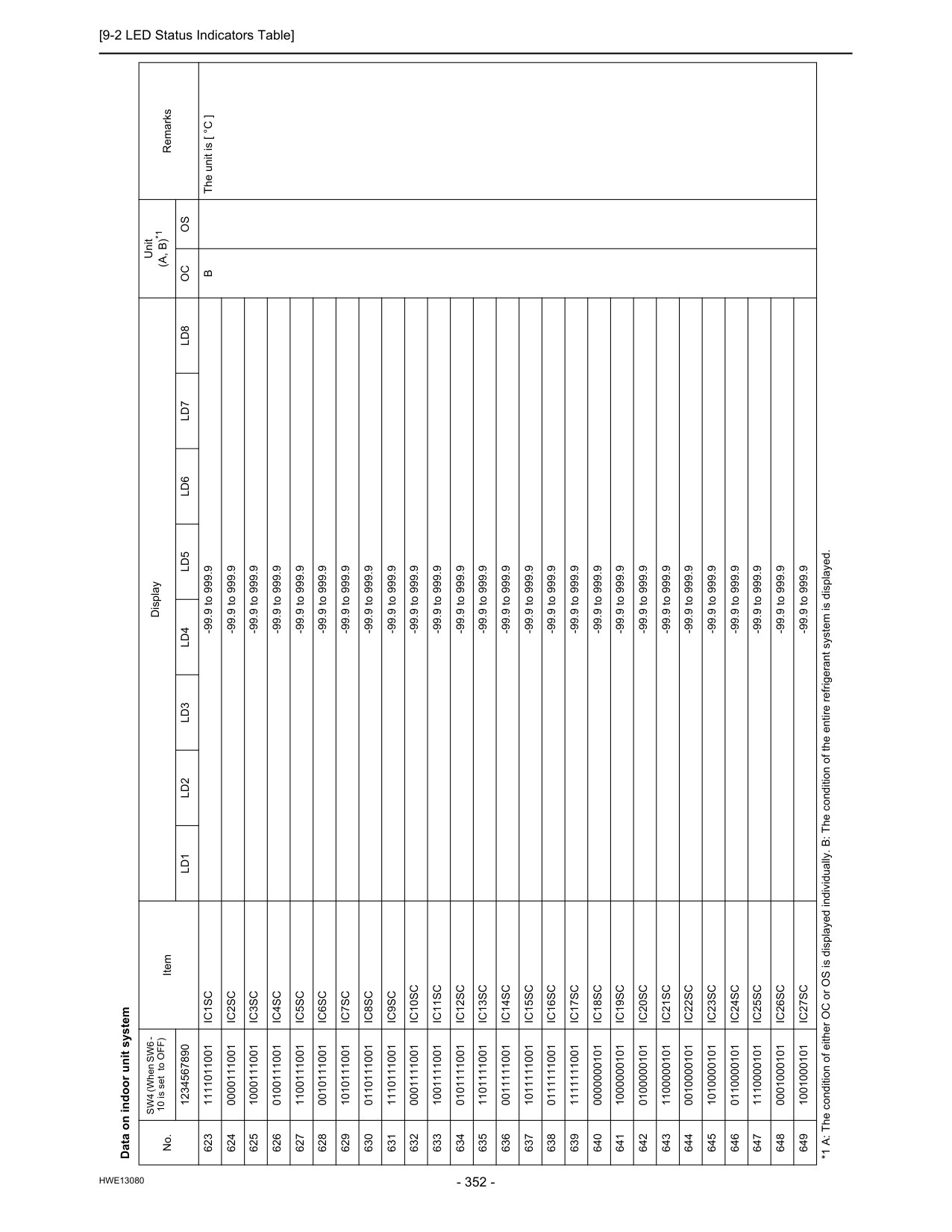
[9-2 LED Status Indicators Table]
Hwe13080
Data on indoor unit system No. SW4 (When SW6 - 10 is set to OFF) Item Display Unit(A, B)*1
Remarks 1234567890Ld1
Ld2
Ld3
Ld4
Ld5
Ld6
Ld7
Ld8
Oc
Os
623 1111011001Ic1Sc
-99.9 to 999.9B
The unit is [ °C ] 624 0000111001Ic2Sc
-99.9 to 999.9 625 1000111001Ic3Sc
-99.9 to 999.9 626 0100111001Ic4Sc
-99.9 to 999.9 627 1100111001Ic5Sc
-99.9 to 999.9 628 0010111001Ic6Sc
-99.9 to 999.9 629 1010111001Ic7Sc
-99.9 to 999.9 630 0110111001Ic8Sc
-99.9 to 999.9 631 1110111001Ic9Sc
-99.9 to 999.9 632 0001111001Ic10Sc
-99.9 to 999.9 633 1001111001Ic11Sc
-99.9 to 999.9 634 0101111001Ic12Sc
-99.9 to 999.9 635 1101111001Ic13Sc
-99.9 to 999.9 636 0011111001Ic14Sc
-99.9 to 999.9 637 1011111001Ic15Sc
-99.9 to 999.9 638 0111111001Ic16Sc
-99.9 to 999.9 639 1111111001Ic17Sc
-99.9 to 999.9 640 0000000101Ic18Sc
-99.9 to 999.9 641 1000000101Ic19Sc
-99.9 to 999.9 642 0100000101Ic20Sc
-99.9 to 999.9 643 1100000101Ic21Sc
-99.9 to 999.9 644 0010000101Ic22Sc
-99.9 to 999.9 645 1010000101Ic23Sc
-99.9 to 999.9 646 0110000101Ic24Sc
-99.9 to 999.9 647 1110000101Ic25Sc
-99.9 to 999.9 648 0001000101Ic26Sc
-99.9 to 999.9 649 1001000101Ic27Sc
-99.9 to 999.9 *1 A: The condition of either OC or OS is displayed individually. B: The condition of the entire refrigerant system is displayed.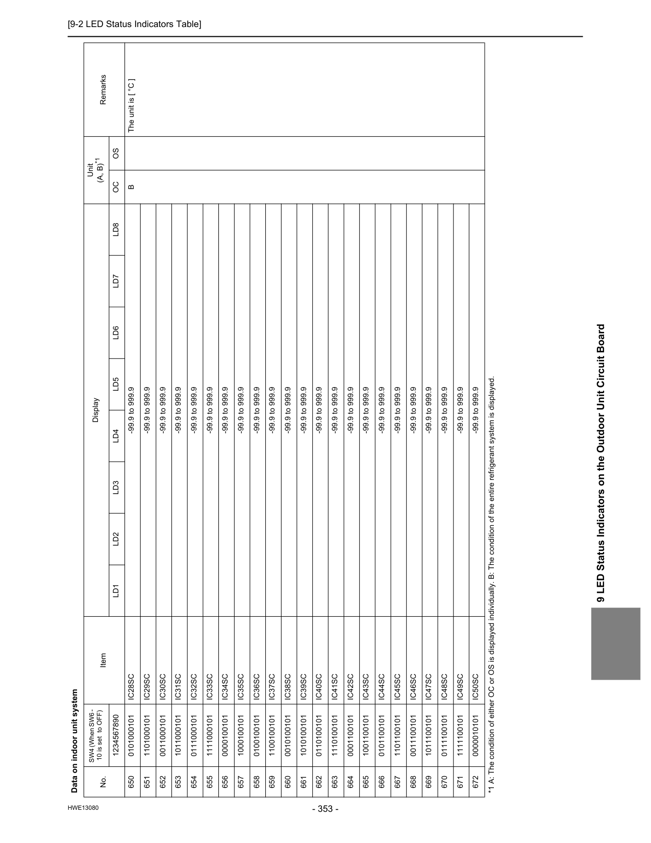
[9-2 LED Status Indicators Table]
Hwe13080
9 LED Status Indicators on the Outdoor Unit Circuit Board 650 0101000101Ic28Sc
-99.9 to 999.9B
The unit is [ °C ] 651 1101000101Ic29Sc
-99.9 to 999.9 652 0011000101Ic30Sc
-99.9 to 999.9 653 1011000101Ic31Sc
-99.9 to 999.9 654 0111000101Ic32Sc
-99.9 to 999.9 655 1111000101Ic33Sc
-99.9 to 999.9 656 0000100101Ic34Sc
-99.9 to 999.9 657 1000100101Ic35Sc
-99.9 to 999.9 658 0100100101Ic36Sc
-99.9 to 999.9 659 1100100101Ic37Sc
-99.9 to 999.9 660 0010100101Ic38Sc
-99.9 to 999.9 661 1010100101Ic39Sc
-99.9 to 999.9 662 0110100101Ic40Sc
-99.9 to 999.9 663 1110100101Ic41Sc
-99.9 to 999.9 664 0001100101Ic42Sc
-99.9 to 999.9 665 1001100101Ic43Sc
-99.9 to 999.9 666 0101100101Ic44Sc
-99.9 to 999.9 667 1101100101Ic45Sc
-99.9 to 999.9 668 0011100101Ic46Sc
-99.9 to 999.9 669 1011100101Ic47Sc
-99.9 to 999.9 670 0111100101Ic48Sc
-99.9 to 999.9 671 1111100101Ic49Sc
-99.9 to 999.9 672 0000010101Ic50Sc
-99.9 to 999.9 Data on indoor unit system No. SW4 (When SW6 - 10 is set to OFF) Item Display Unit(A, B)*1
Remarks 1234567890Ld1
Ld2
Ld3
Ld4
Ld5
Ld6
Ld7
Ld8
Oc
Os
*1 A: The condition of either OC or OS is displayed individually. B: The condition of the entire refrigerant system is displayed.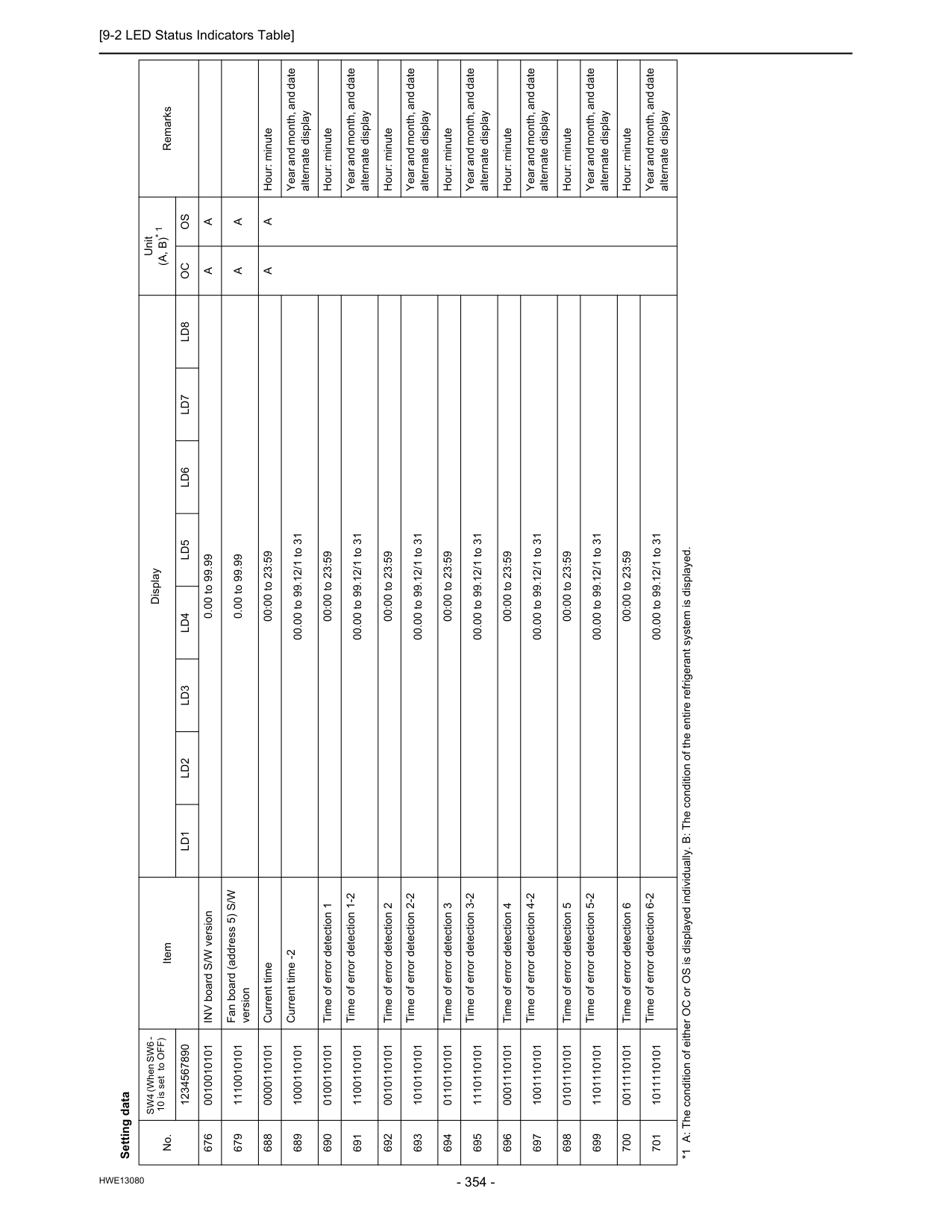
[9-2 LED Status Indicators Table]
Hwe13080
Setting data No. SW4 (When SW6 - 10 is set to OFF) Item Display Unit(A, B)* 1
Remarks 1234567890Ld1
Ld2
Ld3
Ld4
Ld5
Ld6
Ld7
Ld8
Oc
Os
676 0010010101 INV board S/W version 0.00 to 99.99A
A
679 1110010101 Fan board (address 5) S/W version 0.00 to 99.99A
A
688 0000110101 Current time 00:00 to 23:59A
A
Hour: minute 689 1000110101 Current time -2 00.00 to 99.12/1 to 31 Year and month, and date alternate display 690 0100110101 Time of error detection 1 00:00 to 23:59 Hour: minute 691 1100110101 Time of error detection 1-2 00.00 to 99.12/1 to 31 Year and month, and date alternate display 692 0010110101 Time of error detection 2 00:00 to 23:59 Hour: minute 693 1010110101 Time of error detection 2-2 00.00 to 99.12/1 to 31 Year and month, and date alternate display 694 0110110101 Time of error detection 3 00:00 to 23:59 Hour: minute 695 1110110101 Time of error detection 3-2 00.00 to 99.12/1 to 31 Year and month, and date alternate display 696 0001110101 Time of error detection 4 00:00 to 23:59 Hour: minute 697 1001110101 Time of error detection 4-2 00.00 to 99.12/1 to 31 Year and month, and date alternate display 698 0101110101 Time of error detection 5 00:00 to 23:59 Hour: minute 699 1101110101 Time of error detection 5-2 00.00 to 99.12/1 to 31 Year and month, and date alternate display 700 0011110101 Time of error detection 6 00:00 to 23:59 Hour: minute 701 1011110101 Time of error detection 6-2 00.00 to 99.12/1 to 31 Year and month, and date alternate display *1 A: The condition of either OC or OS is displayed individually. B: The condition of the entire refrigerant system is displayed.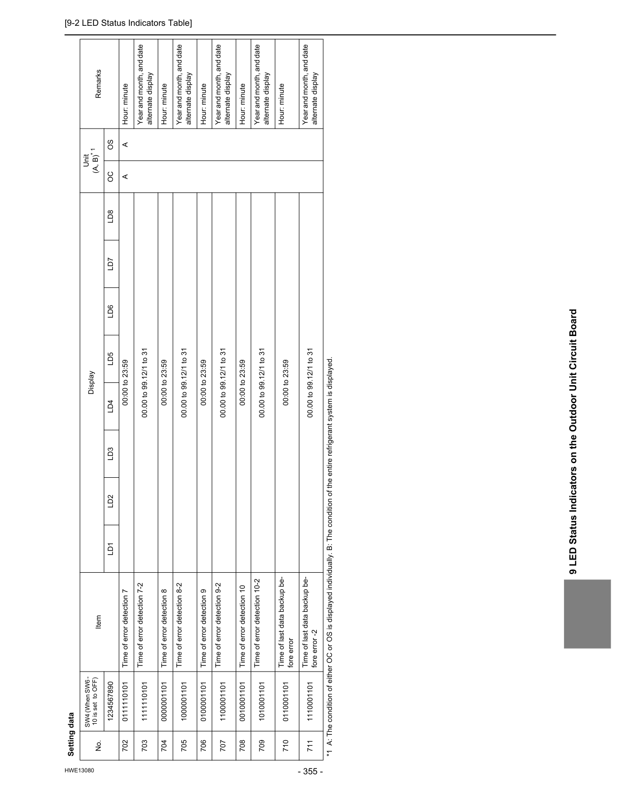
[9-2 LED Status Indicators Table]
Hwe13080
9 LED Status Indicators on the Outdoor Unit Circuit Board 702 0111110101 Time of error detection 7 00:00 to 23:59A
A
Hour: minute 703 1111110101 Time of error detection 7-2 00.00 to 99.12/1 to 31 Year and month, and date alternate display 704 0000001101 Time of error detection 8 00:00 to 23:59 Hour: minute 705 1000001101 Time of error detection 8-2 00.00 to 99.12/1 to 31 Year and month, and date alternate display 706 0100001101 Time of error detection 9 00:00 to 23:59 Hour: minute 707 1100001101 Time of error detection 9-2 00.00 to 99.12/1 to 31 Year and month, and date alternate display 708 0010001101 Time of error detection 10 00:00 to 23:59 Hour: minute 709 1010001101 Time of error detection 10-2 00.00 to 99.12/1 to 31 Year and month, and date alternate display 710 0110001101 Time of last data backup be- fore error 00:00 to 23:59 Hour: minute 711 1110001101 Time of last data backup be- fore error -2 00.00 to 99.12/1 to 31 Year and month, and date alternate display Setting data No. SW4 (When SW6 - 10 is set to OFF) Item Display Unit(A, B)* 1
Remarks 1234567890Ld1
Ld2
Ld3
Ld4
Ld5
Ld6
Ld7
Ld8
Oc
Os
*1 A: The condition of either OC or OS is displayed individually. B: The condition of the entire refrigerant system is displayed.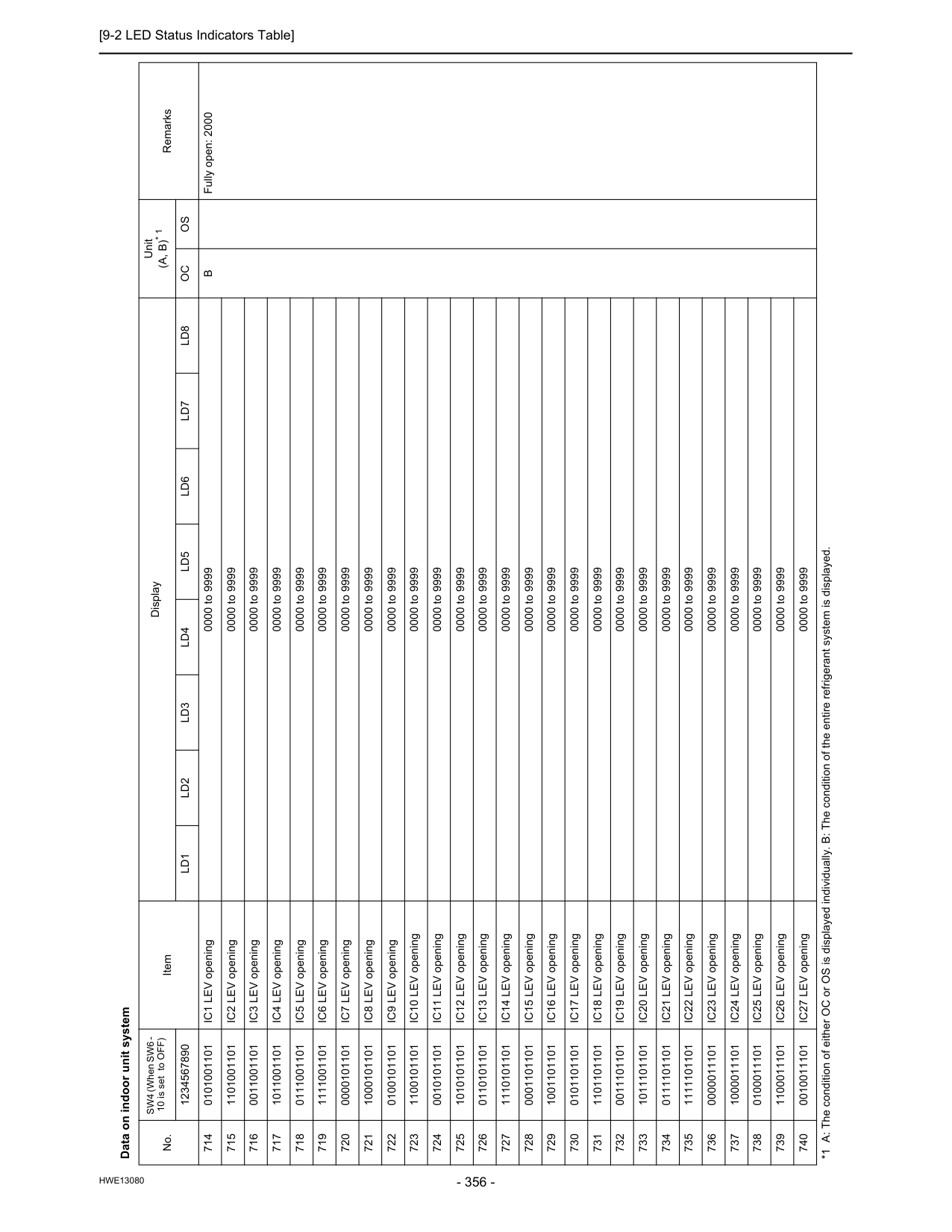
[9-2 LED Status Indicators Table]
Hwe13080
Data on indoor unit system No. SW4 (When SW6 - 10 is set to OFF) Item Display Unit(A, B)* 1
Remarks 1234567890Ld1
Ld2
Ld3
Ld4
Ld5
Ld6
Ld7
Ld8
Oc
Os
714 0101001101 IC1 LEV opening 0000 to 9999B
Fully open: 2000 715 1101001101 IC2 LEV opening 0000 to 9999 716 0011001101 IC3 LEV opening 0000 to 9999 717 1011001101 IC4 LEV opening 0000 to 9999 718 0111001101 IC5 LEV opening 0000 to 9999 719 1111001101 IC6 LEV opening 0000 to 9999 720 0000101101 IC7 LEV opening 0000 to 9999 721 1000101101 IC8 LEV opening 0000 to 9999 722 0100101101 IC9 LEV opening 0000 to 9999 723 1100101101 IC10 LEV opening 0000 to 9999 724 0010101101 IC11 LEV opening 0000 to 9999 725 1010101101 IC12 LEV opening 0000 to 9999 726 0110101101 IC13 LEV opening 0000 to 9999 727 1110101101 IC14 LEV opening 0000 to 9999 728 0001101101 IC15 LEV opening 0000 to 9999 729 1001101101 IC16 LEV opening 0000 to 9999 730 0101101101 IC17 LEV opening 0000 to 9999 731 1101101101 IC18 LEV opening 0000 to 9999 732 0011101101 IC19 LEV opening 0000 to 9999 733 1011101101 IC20 LEV opening 0000 to 9999 734 0111101101 IC21 LEV opening 0000 to 9999 735 1111101101 IC22 LEV opening 0000 to 9999 736 0000011101 IC23 LEV opening 0000 to 9999 737 1000011101 IC24 LEV opening 0000 to 9999 738 0100011101 IC25 LEV opening 0000 to 9999 739 1100011101 IC26 LEV opening 0000 to 9999 740 0010011101 IC27 LEV opening 0000 to 9999 *1 A: The condition of either OC or OS is displayed individually. B: The condition of the entire refrigerant system is displayed.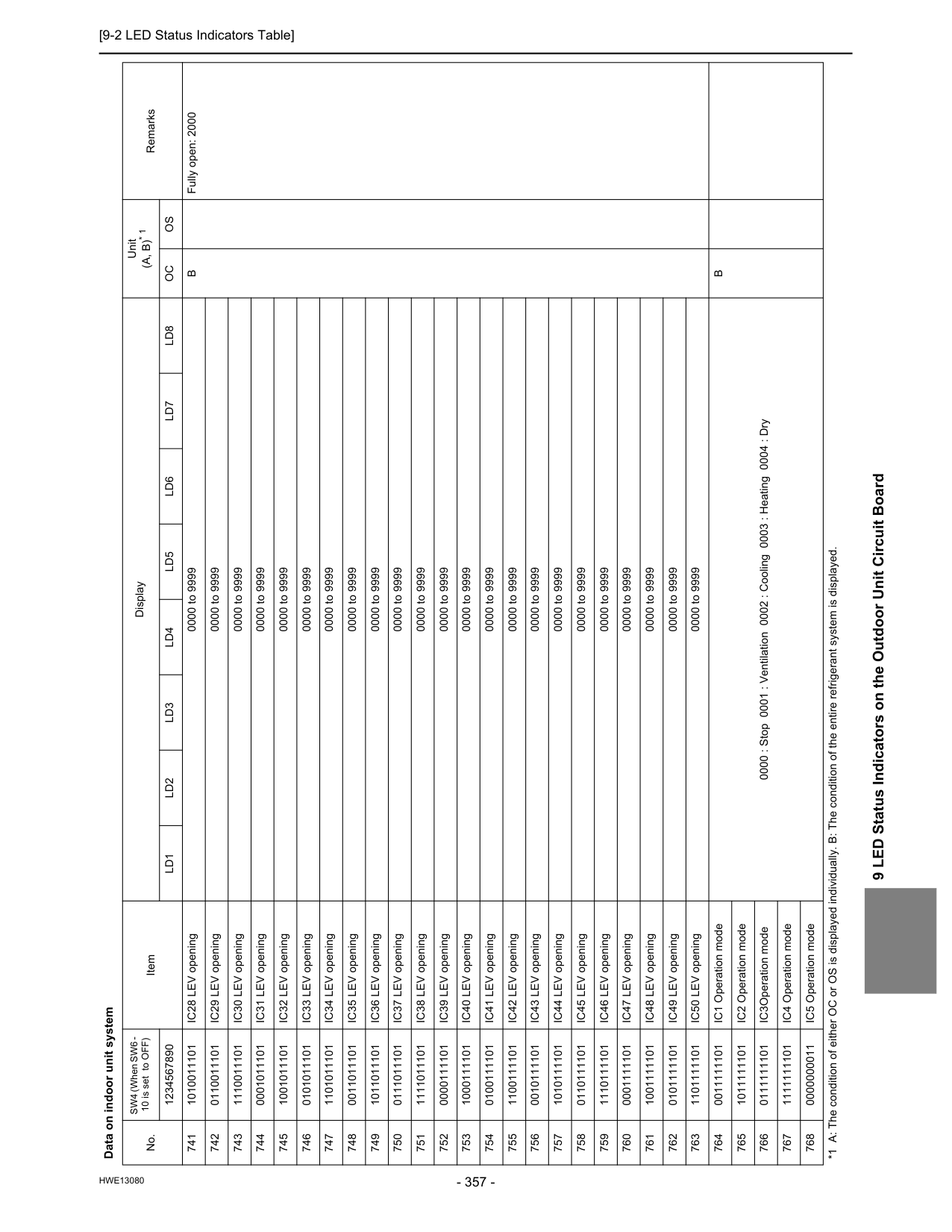
[9-2 LED Status Indicators Table]
Hwe13080
9 LED Status Indicators on the Outdoor Unit Circuit Board 741 1010011101 IC28 LEV opening 0000 to 9999B
Fully open: 2000 742 0110011101 IC29 LEV opening 0000 to 9999 743 1110011101 IC30 LEV opening 0000 to 9999 744 0001011101 IC31 LEV opening 0000 to 9999 745 1001011101 IC32 LEV opening 0000 to 9999 746 0101011101 IC33 LEV opening 0000 to 9999 747 1101011101 IC34 LEV opening 0000 to 9999 748 0011011101 IC35 LEV opening 0000 to 9999 749 1011011101 IC36 LEV opening 0000 to 9999 750 0111011101 IC37 LEV opening 0000 to 9999 751 1111011101 IC38 LEV opening 0000 to 9999 752 0000111101 IC39 LEV opening 0000 to 9999 753 1000111101 IC40 LEV opening 0000 to 9999 754 0100111101 IC41 LEV opening 0000 to 9999 755 1100111101 IC42 LEV opening 0000 to 9999 756 0010111101 IC43 LEV opening 0000 to 9999 757 1010111101 IC44 LEV opening 0000 to 9999 758 0110111101 IC45 LEV opening 0000 to 9999 759 1110111101 IC46 LEV opening 0000 to 9999 760 0001111101 IC47 LEV opening 0000 to 9999 761 1001111101 IC48 LEV opening 0000 to 9999 762 0101111101 IC49 LEV opening 0000 to 9999 763 1101111101 IC50 LEV opening 0000 to 9999 764 0011111101 IC1 Operation mode 0000 : Stop 0001 : Ventilation 0002 : Cooling 0003 : Heating 0004 : DryB
765 1011111101 IC2 Operation mode 766 0111111101 IC3Operation mode 767 1111111101 IC4 Operation mode 768 0000000011 IC5 Operation mode Data on indoor unit system No. SW4 (When SW6 - 10 is set to OFF) Item Display Unit(A, B)* 1
Remarks 1234567890Ld1
Ld2
Ld3
Ld4
Ld5
Ld6
Ld7
Ld8
Oc
Os
*1 A: The condition of either OC or OS is displayed individually. B: The condition of the entire refrigerant system is displayed.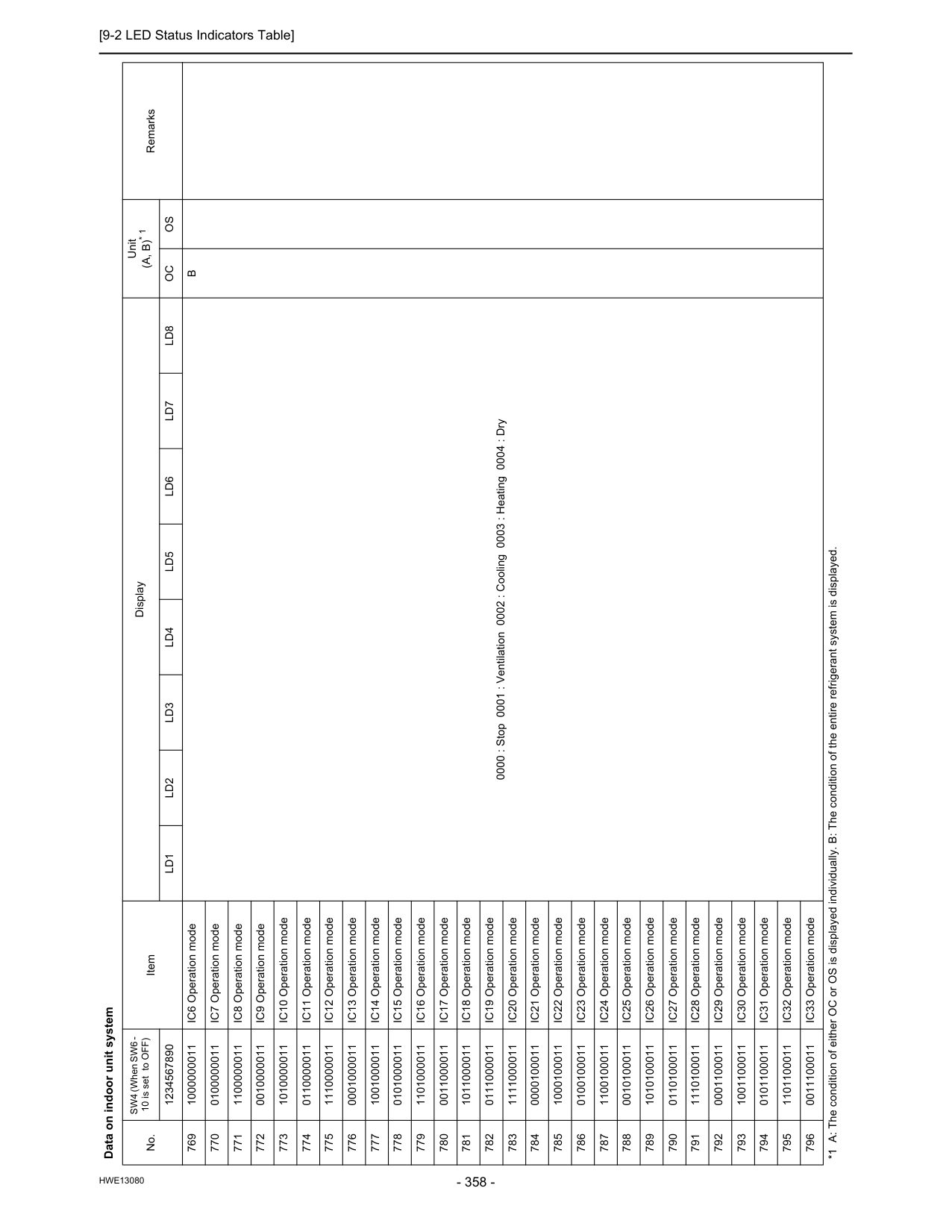
[9-2 LED Status Indicators Table]
Hwe13080
769 1000000011 IC6 Operation mode 0000 : Stop 0001 : Ventilation 0002 : Cooling 0003 : Heating 0004 : DryB
770 0100000011 IC7 Operation mode 771 1100000011 IC8 Operation mode 772 0010000011 IC9 Operation mode 773 1010000011 IC10 Operation mode 774 0110000011 IC11 Operation mode 775 1110000011 IC12 Operation mode 776 0001000011 IC13 Operation mode 777 1001000011 IC14 Operation mode 778 0101000011 IC15 Operation mode 779 1101000011 IC16 Operation mode 780 0011000011 IC17 Operation mode 781 1011000011 IC18 Operation mode 782 0111000011 IC19 Operation mode 783 1111000011 IC20 Operation mode 784 0000100011 IC21 Operation mode 785 1000100011 IC22 Operation mode 786 0100100011 IC23 Operation mode 787 1100100011 IC24 Operation mode 788 0010100011 IC25 Operation mode 789 1010100011 IC26 Operation mode 790 0110100011 IC27 Operation mode 791 1110100011 IC28 Operation mode 792 0001100011 IC29 Operation mode 793 1001100011 IC30 Operation mode 794 0101100011 IC31 Operation mode 795 1101100011 IC32 Operation mode 796 0011100011 IC33 Operation mode Data on indoor unit system No. SW4 (When SW6 - 10 is set to OFF) Item Display Unit(A, B)* 1
Remarks 1234567890Ld1
Ld2
Ld3
Ld4
Ld5
Ld6
Ld7
Ld8
Oc
Os
*1 A: The condition of either OC or OS is displayed individually. B: The condition of the entire refrigerant system is displayed.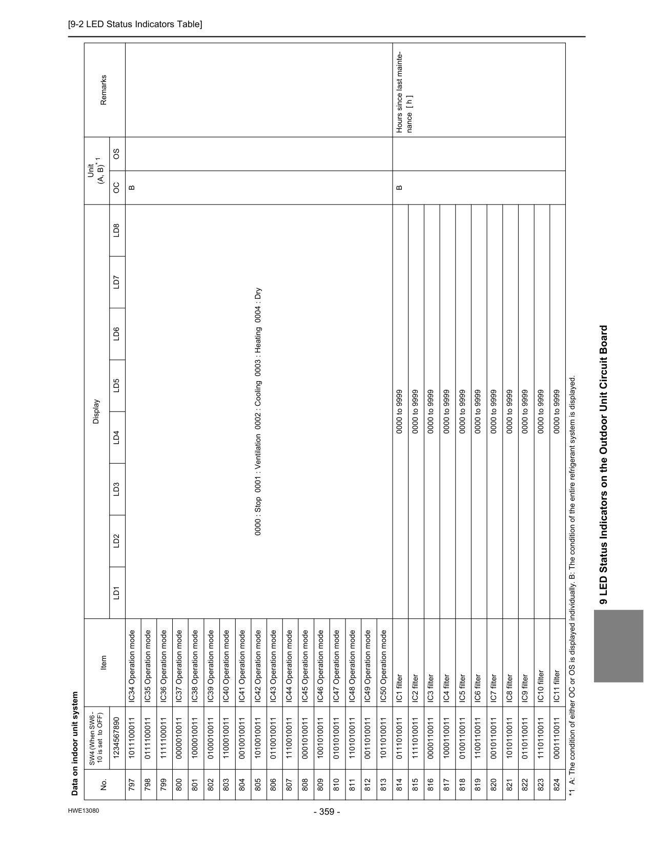
[9-2 LED Status Indicators Table]
Hwe13080
9 LED Status Indicators on the Outdoor Unit Circuit Board 797 1011100011 IC34 Operation mode 0000 : Stop 0001 : Ventilation 0002 : Cooling 0003 : Heating 0004 : DryB
798 0111100011 IC35 Operation mode 799 1111100011 IC36 Operation mode 800 0000010011 IC37 Operation mode 801 1000010011 IC38 Operation mode 802 0100010011 IC39 Operation mode 803 1100010011 IC40 Operation mode 804 0010010011 IC41 Operation mode 805 1010010011 IC42 Operation mode 806 0110010011 IC43 Operation mode 807 1110010011 IC44 Operation mode 808 0001010011 IC45 Operation mode 809 1001010011 IC46 Operation mode 810 0101010011 IC47 Operation mode 811 1101010011 IC48 Operation mode 812 0011010011 IC49 Operation mode 813 1011010011 IC50 Operation mode 814 0111010011 IC1 filter 0000 to 9999B
Hours since last mainte- nance [ h ] 815 1111010011 IC2 filter 0000 to 9999 816 0000110011 IC3 filter 0000 to 9999 817 1000110011 IC4 filter 0000 to 9999 818 0100110011 IC5 filter 0000 to 9999 819 1100110011 IC6 filter 0000 to 9999 820 0010110011 IC7 filter 0000 to 9999 821 1010110011 IC8 filter 0000 to 9999 822 0110110011 IC9 filter 0000 to 9999 823 1110110011 IC10 filter 0000 to 9999 824 0001110011 IC11 filter 0000 to 9999 Data on indoor unit system No. SW4 (When SW6 - 10 is set to OFF) Item Display Unit(A, B)* 1
Remarks 1234567890Ld1
Ld2
Ld3
Ld4
Ld5
Ld6
Ld7
Ld8
Oc
Os
*1 A: The condition of either OC or OS is displayed individually. B: The condition of the entire refrigerant system is displayed.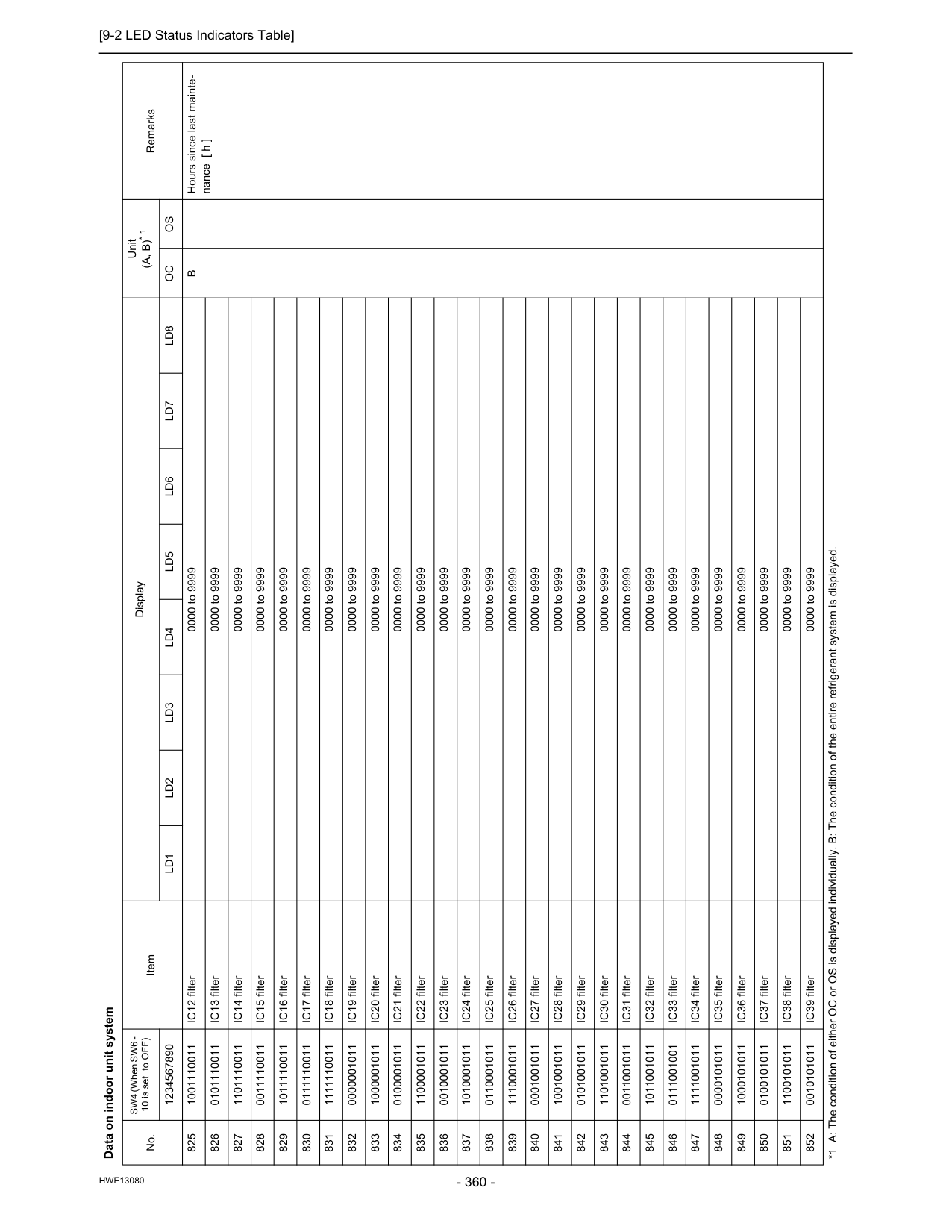
[9-2 LED Status Indicators Table]
Hwe13080
825 1001110011 IC12 filter 0000 to 9999B
Hours since last mainte- nance [ h ] 826 0101110011 IC13 filter 0000 to 9999 827 1101110011 IC14 filter 0000 to 9999 828 0011110011 IC15 filter 0000 to 9999 829 1011110011 IC16 filter 0000 to 9999 830 0111110011 IC17 filter 0000 to 9999 831 1111110011 IC18 filter 0000 to 9999 832 0000001011 IC19 filter 0000 to 9999 833 1000001011 IC20 filter 0000 to 9999 834 0100001011 IC21 filter 0000 to 9999 835 1100001011 IC22 filter 0000 to 9999 836 0010001011 IC23 filter 0000 to 9999 837 1010001011 IC24 filter 0000 to 9999 838 0110001011 IC25 filter 0000 to 9999 839 1110001011 IC26 filter 0000 to 9999 840 0001001011 IC27 filter 0000 to 9999 841 1001001011 IC28 filter 0000 to 9999 842 0101001011 IC29 filter 0000 to 9999 843 1101001011 IC30 filter 0000 to 9999 844 0011001011 IC31 filter 0000 to 9999 845 1011001011 IC32 filter 0000 to 9999 846 0111001001 IC33 filter 0000 to 9999 847 1111001011 IC34 filter 0000 to 9999 848 0000101011 IC35 filter 0000 to 9999 849 1000101011 IC36 filter 0000 to 9999 850 0100101011 IC37 filter 0000 to 9999 851 1100101011 IC38 filter 0000 to 9999 852 0010101011 IC39 filter 0000 to 9999 Data on indoor unit system No. SW4 (When SW6 - 10 is set to OFF) Item Display Unit(A, B)* 1
Remarks 1234567890Ld1
Ld2
Ld3
Ld4
Ld5
Ld6
Ld7
Ld8
Oc
Os
*1 A: The condition of either OC or OS is displayed individually. B: The condition of the entire refrigerant system is displayed.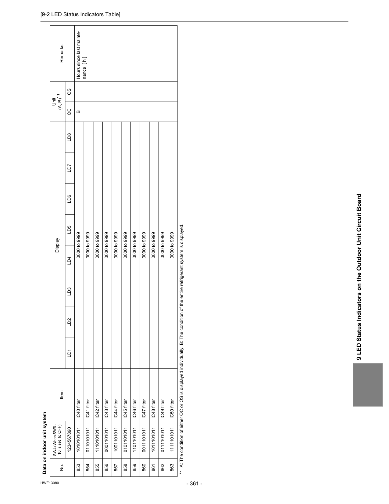
[9-2 LED Status Indicators Table]
Hwe13080
9 LED Status Indicators on the Outdoor Unit Circuit Board 853 1010101011 IC40 filter 0000 to 9999B
Hours since last mainte- nance [ h ] 854 0110101011 IC41 filter 0000 to 9999 855 1110101011 IC42 filter 0000 to 9999 856 0001101011 IC43 filter 0000 to 9999 857 1001101011 IC44 filter 0000 to 9999 858 0101101011 IC45 filter 0000 to 9999 859 1101101011 IC46 filter 0000 to 9999 860 0011101011 IC47 filter 0000 to 9999 861 1011101011 IC48 filter 0000 to 9999 862 0111101011 IC49 filter 0000 to 9999 863 1111101011 IC50 filter 0000 to 9999 Data on indoor unit system No. SW4 (When SW6 - 10 is set to OFF) Item Display Unit(A, B)* 1
Remarks 1234567890Ld1
Ld2
Ld3
Ld4
Ld5
Ld6
Ld7
Ld8
Oc
Os
*1 A: The condition of either OC or OS is displayed individually. B: The condition of the entire refrigerant system is displayed.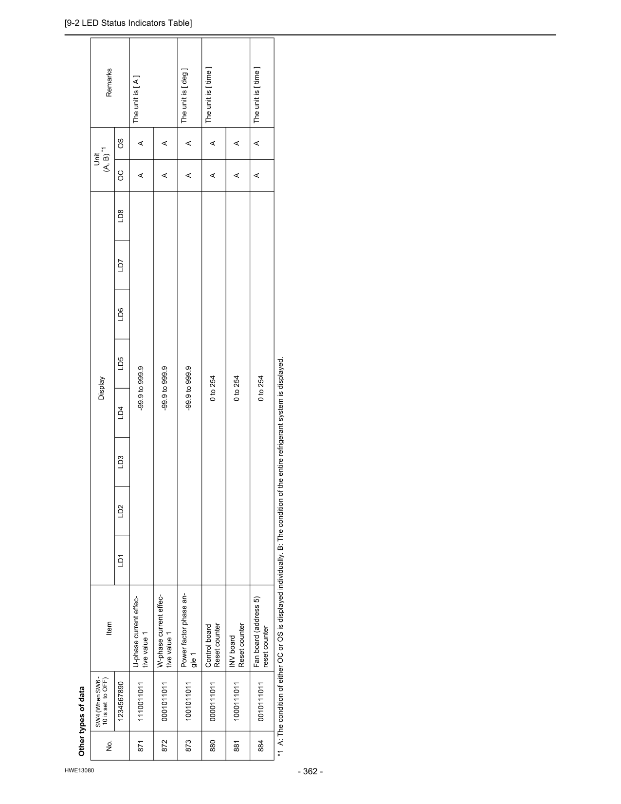
[9-2 LED Status Indicators Table]