
Ask AI
— answers from the official manualAnswers from the official manual.
Common questions
Common Questions
10 totalHow do I install the Carrier Infinity Thermostat?
Begin by turning off all power to the equipment and selecting your mounting type (recessed or surface mount). Route the thermostat wires through the mounting plastic, level it against the wall, and drill two 3/16-inch mounting holes. Strip 1/4 inch of insulation from each wire and match them to the proper terminals on the User Interface backplate according to the wiring diagram. Use 22 AWG wire or larger for normal applications, or 20 AWG for wire lengths over 100 feet. Finally, attach the Infinity Control to the mounting plastic by lining up the plastic guides and pushing it on, then turn on power to the equipment.
What are the correct wire colors for the ABCD connection on the Infinity Thermostat?
The recommended color code for ABCD connections is: A (Green) = Data A, B (Yellow) = Data B, C (White) = 24VAC Common, and D (Red) = 24VAC Hot. While it is not mandatory to use these colors, each ABCD connector in the system MUST be wired consistently throughout. If thermostat wiring is located near high voltage, cable TV, or Ethernet wiring, shielded thermostat wire can be used with the shield connected to ground at the indoor unit only, not at the user interface.
Where should I mount the Infinity Thermostat for accurate temperature readings?
The Infinity Control should be mounted approximately 5 feet from the floor on an inside partitioning wall in a frequently used room where it is easily accessible and visible. It should be on a section of wall without pipes or ductwork, and away from windows, outside walls, doors to the outside, direct light or heat sources, and direct airflow from supply registers. A Remote Room Sensor can be used if the Infinity Control cannot be mounted in an area with optimal airflow, allowing it to be placed in less ideal locations like near exterior doors or in closets.
How do I access the Install/Service menus on the Infinity Thermostat?
Press and hold the ADVANCED button for at least 10 seconds to enter the INSTALL/SERVICE menus. The menu will automatically exit after 60 minutes of no button activity. From this menu, you can access Equipment Summary, Install, Setup, Checkout, and Service options to view system information, add or change equipment, modify settings, test equipment operation, and view fault history.
What should I do if the Infinity Thermostat display says 'Indoor Unit Not Found'?
First, recheck the ABCD wiring on all devices to ensure all colors match for every terminal. Press the left-side button to try again. If the display still reads 'Indoor Unit Not Found,' disconnect accessories and all devices from the ABCD connection and connect the User Interface directly to the indoor unit with a short piece of thermostat wire. Add other devices one at a time to determine where the communication issue exists.
What is the correct procedure for initial power-up of a new Infinity Thermostat?
When power is first applied, the User Interface will display 'Establishing Communications With Equipment PLEASE WAIT,' followed by 'Searching For Equipment' and 'SEARCHING FOR OUTDOOR EQUIPMENT.' The system will automatically identify all Infinity components. You will then be asked to select the outdoor unit type (AC, HP, or None), enter the BTU size, select accessories (filter type, humidifier, UV lights), and review the Equipment Summary. After confirming all selections are correct, the system will perform a static pressure check, which takes about 1½ minutes to complete.
Show 4 more questions
How do I set the time, day, and desired humidity on the Infinity Thermostat?
What error codes indicate a system malfunction on the Infinity Thermostat?
How do I perform a static pressure check on the Infinity Thermostat?
What should I do if I made a mistake during the Infinity Thermostat start-up process?
Full Manual
18 pages
Systxccuid01--V
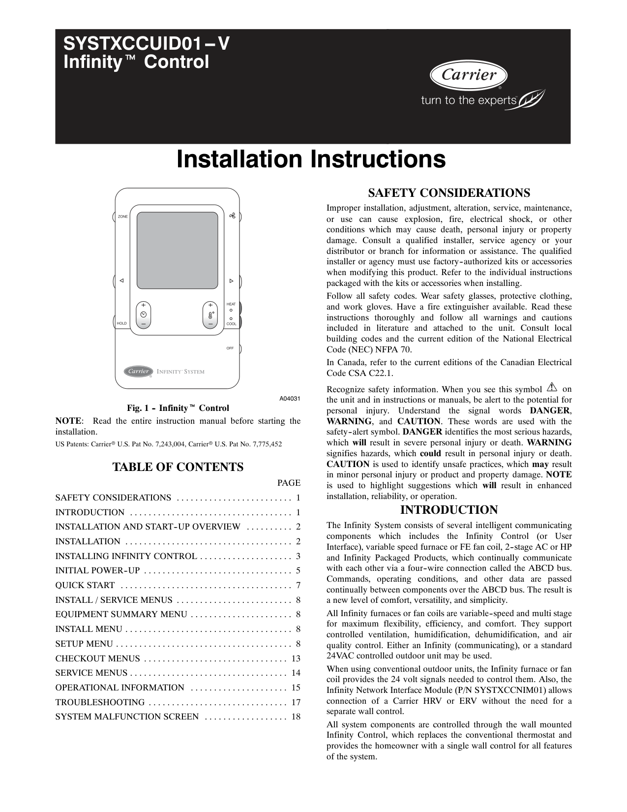
Infinityt Control Installation InstructionsHold
Cool
Heat
Off
Zone
Infinity
™ System
A04031
Fig. 1 -- Infinityt ControlNote:
Read the entire instruction manual before starting the installation. US Patents: Carrierr U.S. Pat No. 7,243,004, Carrierr U.S. Pat No. 7,775,452Table Of Contents
Page
Safety Considerations
1 . . . . . . . . . . . . . . . . . . . . . . . . .Introduction
1 . . . . . . . . . . . . . . . . . . . . . . . . . . . . . . . . . . .Installation And Start--Up Overview
2 . . . . . . . . . .Installation
2 . . . . . . . . . . . . . . . . . . . . . . . . . . . . . . . . . . . .Installing Infinity Control
3 . . . . . . . . . . . . . . . . . . . .Initial Power--Up
5 . . . . . . . . . . . . . . . . . . . . . . . . . . . . . . . .Quick Start
7 . . . . . . . . . . . . . . . . . . . . . . . . . . . . . . . . . . . . .Install / Service Menus
8 . . . . . . . . . . . . . . . . . . . . . . . . .Equipment Summary Menu
8 . . . . . . . . . . . . . . . . . . . . . .Install Menu
8 . . . . . . . . . . . . . . . . . . . . . . . . . . . . . . . . . . . .Setup Menu
8 . . . . . . . . . . . . . . . . . . . . . . . . . . . . . . . . . . . . . .Checkout Menus
13 . . . . . . . . . . . . . . . . . . . . . . . . . . . . . . .Service Menus
14 . . . . . . . . . . . . . . . . . . . . . . . . . . . . . . . . . .Operational Information
15 . . . . . . . . . . . . . . . . . . . . .Troubleshooting
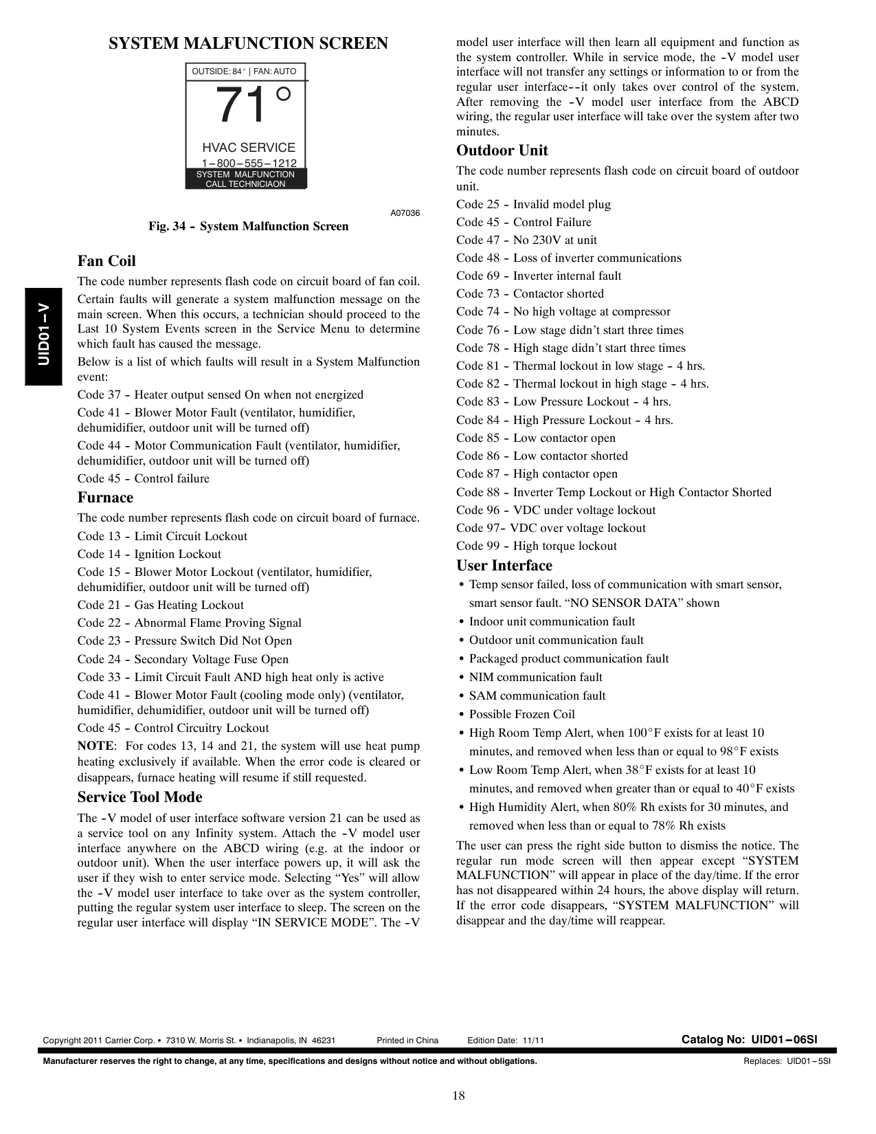
17 . . . . . . . . . . . . . . . . . . . . . . . . . . . . . .System Malfunction Screen
18 . . . . . . . . . . . . . . . . . .Safety Considerations
Improper installation, adjustment, alteration, service, maintenance, or use can cause explosion, fire, electrical shock, or other conditions which may cause death, personal injury or property damage. Consult a qualified installer, service agency or your distributor or branch for information or assistance. The qualified installer or agency must use factory--authorized kits or accessories when modifying this product. Refer to the individual instructions packaged with the kits or accessories when installing. Follow all safety codes. Wear safety glasses, protective clothing, and work gloves. Have a fire extinguisher available. Read these instructions thoroughly and follow all warnings and cautions included in literature and attached to the unit. Consult local building codes and the current edition of the National Electrical Code (NEC) NFPA 70. In Canada, refer to the current editions of the Canadian Electrical Code CSA C22.1. Recognize safety information. When you see this symbol on the unit and in instructions or manuals, be alert to the potential for personal injury. Understand the signal wordsDanger,
WARNING, and CAUTION. These words are used with the safety--alert symbol. DANGER identifies the most serious hazards, which will result in severe personal injury or death. WARNING signifies hazards, which could result in personal injury or death. CAUTION is used to identify unsafe practices, which may result in minor personal injury or product and property damage. NOTE is used to highlight suggestions which will result in enhanced installation, reliability, or operation.Introduction
The Infinity System consists of several intelligent communicating components which includes the Infinity Control (or User Interface), variable speed furnace or FE fan coil, 2--stage AC or HP and Infinity Packaged Products, which continually communicate with each other via a four--wire connection called the ABCD bus. Commands, operating conditions, and other data are passed continually between components over the ABCD bus. The result is a new level of comfort, versatility, and simplicity. All Infinity furnaces or fan coils are variable--speed and multi stage for maximum flexibility, efficiency, and comfort. They support controlled ventilation, humidification, dehumidification, and air quality control. Either an Infinity (communicating), or a standard 24VAC controlled outdoor unit may be used. When using conventional outdoor units, the Infinity furnace or fan coil provides the 24 volt signals needed to control them. Also, the Infinity Network Interface Module (P/N SYSTXCCNIM01) allows connection of a Carrier HRV or ERV without the need for a separate wall control. All system components are controlled through the wall mounted Infinity Control, which replaces the conventional thermostat and provides the homeowner with a single wall control for all features of the system.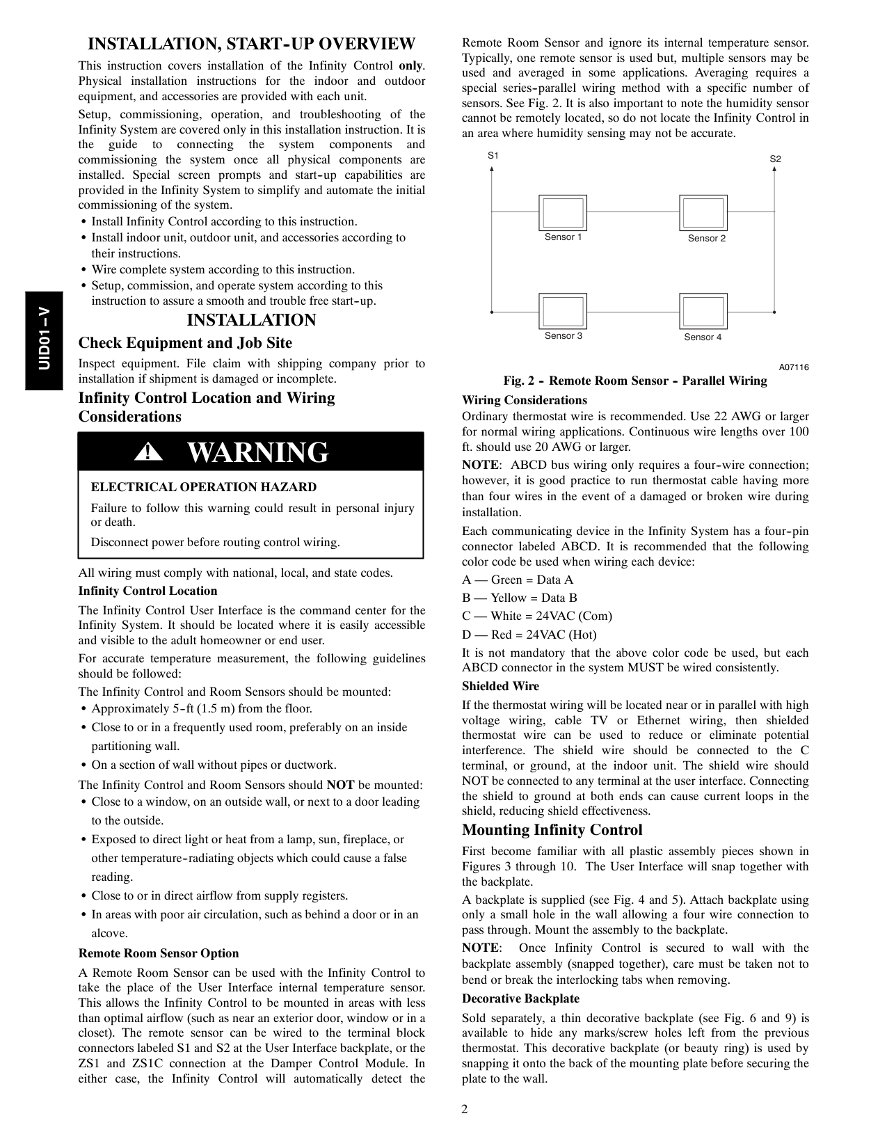
2
Installation, Start--Up Overview
This instruction covers installation of the Infinity Control only. Physical installation instructions for the indoor and outdoor equipment, and accessories are provided with each unit. Setup, commissioning, operation, and troubleshooting of the Infinity System are covered only in this installation instruction. It is the guide to connecting the system components and commissioning the system once all physical components are installed. Special screen prompts and start--up capabilities are provided in the Infinity System to simplify and automate the initial commissioning of the system. S Install Infinity Control according to this instruction. S Install indoor unit, outdoor unit, and accessories according to their instructions. S Wire complete system according to this instruction. S Setup, commission, and operate system according to this instruction to assure a smooth and trouble free start--up.Installation
Check Equipment and Job Site Inspect equipment. File claim with shipping company prior to installation if shipment is damaged or incomplete. Infinity Control Location and Wiring ConsiderationsElectrical Operation Hazard
Failure to follow this warning could result in personal injury or death. Disconnect power before routing control wiring. !Warning
All wiring must comply with national, local, and state codes. Infinity Control Location The Infinity Control User Interface is the command center for the Infinity System. It should be located where it is easily accessible and visible to the adult homeowner or end user. For accurate temperature measurement, the following guidelines should be followed: The Infinity Control and Room Sensors should be mounted: S Approximately 5--ft (1.5 m) from the floor. S Close to or in a frequently used room, preferably on an inside partitioning wall. S On a section of wall without pipes or ductwork. The Infinity Control and Room Sensors should NOT be mounted: S Close to a window, on an outside wall, or next to a door leading to the outside. S Exposed to direct light or heat from a lamp, sun, fireplace, or other temperature--radiating objects which could cause a false reading. S Close to or in direct airflow from supply registers. S In areas with poor air circulation, such as behind a door or in an alcove. Remote Room Sensor Option A Remote Room Sensor can be used with the Infinity Control to take the place of the User Interface internal temperature sensor. This allows the Infinity Control to be mounted in areas with less than optimal airflow (such as near an exterior door, window or in a closet). The remote sensor can be wired to the terminal block connectors labeled S1 and S2 at the User Interface backplate, or the ZS1 and ZS1C connection at the Damper Control Module. In either case, the Infinity Control will automatically detect the Remote Room Sensor and ignore its internal temperature sensor. Typically, one remote sensor is used but, multiple sensors may be used and averaged in some applications. Averaging requires a special series--parallel wiring method with a specific number of sensors. See Fig. 2. It is also important to note the humidity sensor cannot be remotely located, so do not locate the Infinity Control in an area where humidity sensing may not be accurate. Sensor 1 Sensor 2 Sensor 3 Sensor 4S1
S2
A07116
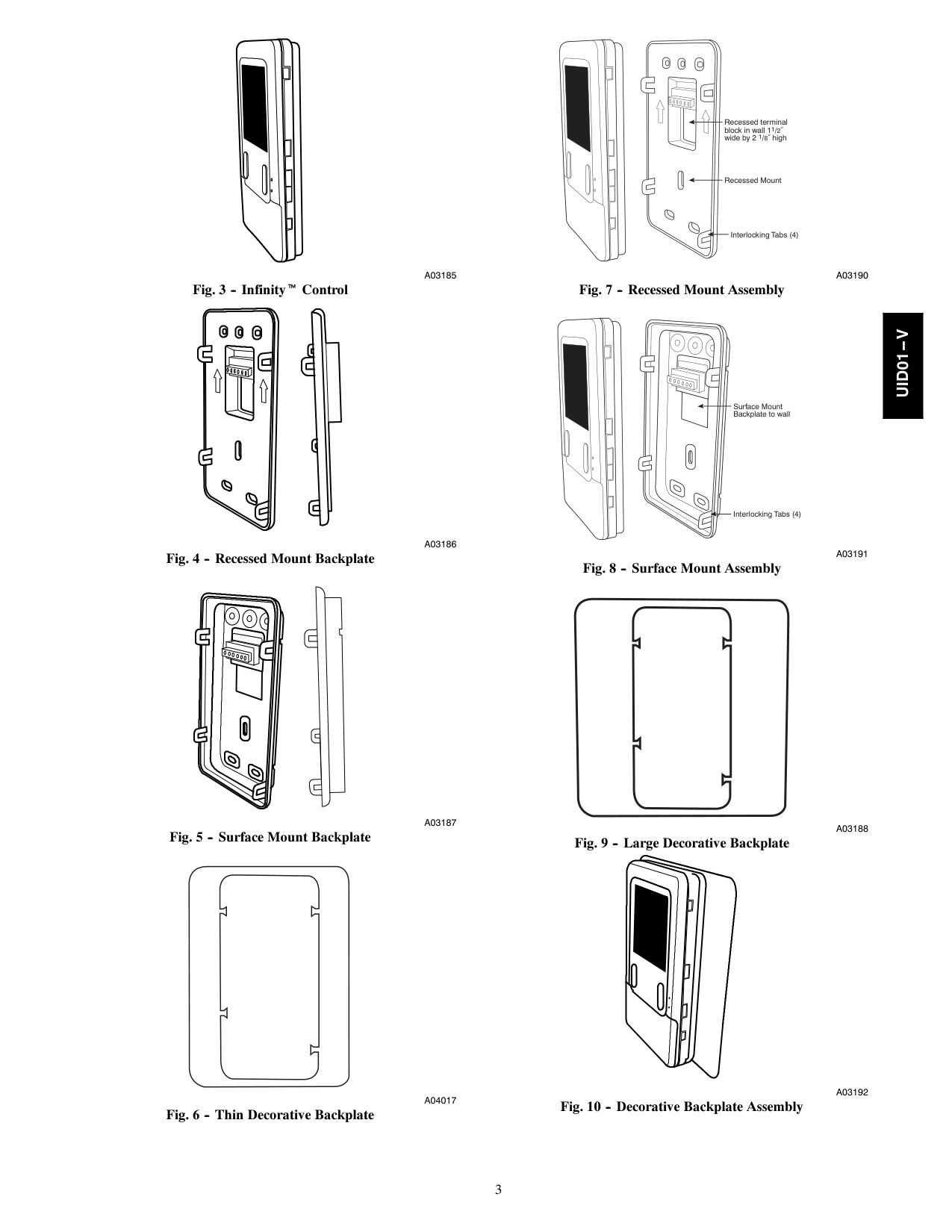
Fig. 2 -- Remote Room Sensor -- Parallel Wiring Wiring Considerations Ordinary thermostat wire is recommended. Use 22 AWG or larger for normal wiring applications. Continuous wire lengths over 100 ft. should use 20 AWG or larger. NOTE: ABCD bus wiring only requires a four--wire connection; however, it is good practice to run thermostat cable having more than four wires in the event of a damaged or broken wire during installation. Each communicating device in the Infinity System has a four--pin connector labeled ABCD. It is recommended that the following color code be used when wiring each device: A — Green = Data A B — Yellow = Data B C — White = 24VAC (Com) D — Red = 24VAC (Hot) It is not mandatory that the above color code be used, but each ABCD connector in the system MUST be wired consistently. Shielded Wire If the thermostat wiring will be located near or in parallel with high voltage wiring, cable TV or Ethernet wiring, then shielded thermostat wire can be used to reduce or eliminate potential interference. The shield wire should be connected to the C terminal, or ground, at the indoor unit. The shield wire should NOT be connected to any terminal at the user interface. Connecting the shield to ground at both ends can cause current loops in the shield, reducing shield effectiveness. Mounting Infinity Control First become familiar with all plastic assembly pieces shown in Figures 3 through 10. The User Interface will snap together with the backplate. A backplate is supplied (see Fig. 4 and 5). Attach backplate using only a small hole in the wall allowing a four wire connection to pass through. Mount the assembly to the backplate.Note:
Once Infinity Control is secured to wall with the backplate assembly (snapped together), care must be taken not to bend or break the interlocking tabs when removing. Decorative Backplate Sold separately, a thin decorative backplate (see Fig. 6 and 9) is available to hide any marks/screw holes left from the previous thermostat. This decorative backplate (or beauty ring) is used by snapping it onto the back of the mounting plate before securing the plate to the wall.Uid01--V
3
A03185
Fig. 3 -- Infinityt ControlA03186
Fig. 4 -- Recessed Mount BackplateA03187
Fig. 5 -- Surface Mount BackplateA04017
Fig. 6 -- Thin Decorative Backplate Recessed terminal block in wall 11/2˝ wide by 2 1/8˝ high Recessed Mount Interlocking Tabs (4)A03190
Fig. 7 -- Recessed Mount Assembly Surface Mount Backplate to wall Interlocking Tabs (4)A03191
Fig. 8 -- Surface Mount AssemblyA03188
Fig. 9 -- Large Decorative BackplateA03192
Fig. 10 -- Decorative Backplate AssemblyUid01--V
4
Electrical Operation Hazard
Failure to follow this warning could result in personal injury, death or equipment damage. Before installing, modifying, or servicing system, the main electrical disconnect switch must be in the OFF position. There may be more than 1 disconnect switch. Lock out and tag switch with a suitable warning label. !Warning
A
B
C
D
A
B
C
D
User Interface Green Yellow White RedOat
Optional Remote Room SensorHum
Com
24V
Humidifier ConnectionS2
S1
A
B
C
D
Abcd
Connections Communicating AC or HP Green Yellow White RedOat
Sensor (Optional) Variable-Speed Furnace/ Fan CoilA03146
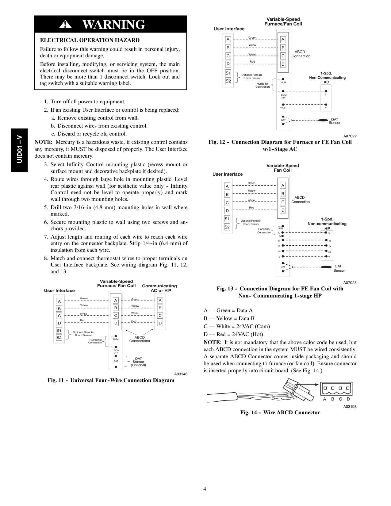
Fig. 11 -- Universal Four--Wire Connection DiagramA
B
C
D
A
B
C
D
C
Y
Abcd
Connection User Interface 1-Spd. Non-CommunicatingAc
Green Yellow White Red Optional Remote Room SensorHum
Com
24V
Humidifier ConnectionY/Y2
S2
S1
Oat
Oat
Sensor Variable-Speed Furnace/Fan CoilA07022
Fig. 12 -- Connection Diagram for Furnace or FE Fan Coil w/1--Stage ACA
B
C
D
A
B
C
D
Abcd
Connection User Interface 1-Spd. Non-communicatingHp
Green Yellow White Red Optional Remote Room SensorHum
C
Humidifier ConnectionY
S2
S1
W2
Y
O
C
R
O
R
W
Oat
Oat
Sensor Variable-Speed Fan CoilG
A07023
Fig. 13 -- Connection Diagram for FE Fan Coil with Non-- Communicating 1--stage HP A — Green = Data A B — Yellow = Data B C — White = 24VAC (Com) D — Red = 24VAC (Hot) NOTE: It is not mandatory that the above color code be used, but each ABCD connection in the system MUST be wired consistently. A separate ABCD Connector comes inside packaging and should be used when connecting to furnace (or fan coil). Ensure connector is inserted properly into circuit board. (See Fig. 14.)A
B
C
D
A03193
Fig. 14 -- Wire ABCD ConnectorUid01--V
5
Electrical Operation Hazard
Failure to follow this caution may result in equipment damage or improper operation. Improper wiring of the ABCD connector will cause the Infinity System to operate improperly. Check to make sure all wiring is correct before proceeding with installation or turning on power.Caution
!Note:
For other applications not listed, refer to the Network Interface Module (NIM) Installation Instructions. Humidifier Connection A 24VAC bypass or fan powered humidifier may be installed. NOTE: Do Not Use a traditional humidistat to control humidifier operation. If a humidifier is installed, let the Infinity Control operate humidifier. Bypass Humidifiers A bypass humidifier should be wired directly to the furnace or fan coil HUM and 24VAC COM terminals. The Infinity Control will automatically energize the HUM output during a call for humidification. Fan Powered Humidifiers Most fan powered humidifiers produce internal 24VAC in order to energize upon a switch or contact closure. For this application, a 24VAC N.O. Isolation Relay (DPST) MUST be used to prevent mixing the internal humidifier power with the indoor equipment transformer. Applying 24VAC isolation relay coil to furnace or fan coil HUM and COM terminals will allow the Infinity Control to automatically energize the HUM output during a call for humidification. The N.O. relay contacts will be used to energize the humidifier. See fan powered humidifier installation instructions for more details.Equipment Hazard
Failure to follow this caution may result in equipment damage. Do not apply 24VAC fan powered humidifier (with internal power supply) direct to indoor unit HUM and COM terminals.Caution
!Initial Power--Up
Note:
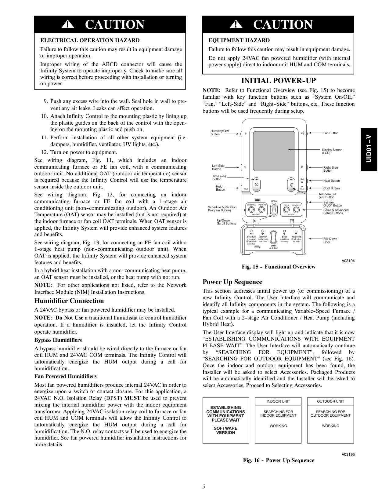
Refer to Functional Overview (see Fig. 15) to become familiar with key function buttons such as “System On/Off,” “Fan,” “Left--Side” and “Right--Side” buttons, etc. These function buttons will be used frequently during setup.Hold
Cool
Heat
Schedule
Vacation
Program
Scroll
Basic
Advanced
Setups
Schedule to program temperature schedule Vacation to start/end vacation Basic to set time, humidity Advanced for all other settings Scroll up & down Fan Button Display Screen(Lcd)
Right-Side Button Heat Button Cool Button Temperature (+/-) Button System On/Off Button Basic & Advanced Setup Buttons Flip Down Door Left-Side Button Humidity/OAT Button Hold Button Time (+/-) Button Schedule & Vacation Program Buttons Up/Down Scroll ButtonsA03194
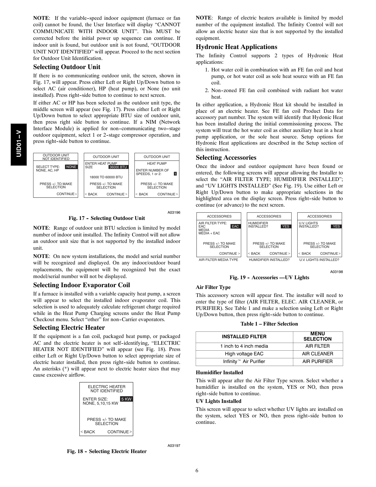
Fig. 15 -- Functional Overview Power Up Sequence This section addresses initial power up (or commissioning) of a new Infinity Control. The User Interface will communicate and identify all Infinity components in the system. The following is a typical example for a communicating Variable--Speed Furnace / Fan Coil with a 2--stage Air Conditioner / Heat Pump (including Hybrid Heat). The User Interface display will light up and indicate that it is now“Establishing Communications With Equipment
PLEASE WAIT”. The User Interface will automatically continue by“Searching
For
Equipment”,
followed by “SEARCHING FOR OUTDOOR EQUIPMENT” (see Fig. 16). Once the indoor and outdoor equipment has been found, the Installer will be asked to select Accessories. Packaged Products will be automatically identified and the Installer will be asked to select Accessories. Proceed to Selecting Accessories.Establishing
Communications
With Equipment
Please Wait
Software
Version
Indoor Unit
Searching For
Indoor Equipment
Working
Outdoor Unit
Searching For
Outdoor Equipment
Working
A03195
Fig. 16 -- Power Up SequenceUid01--V
6
Note:
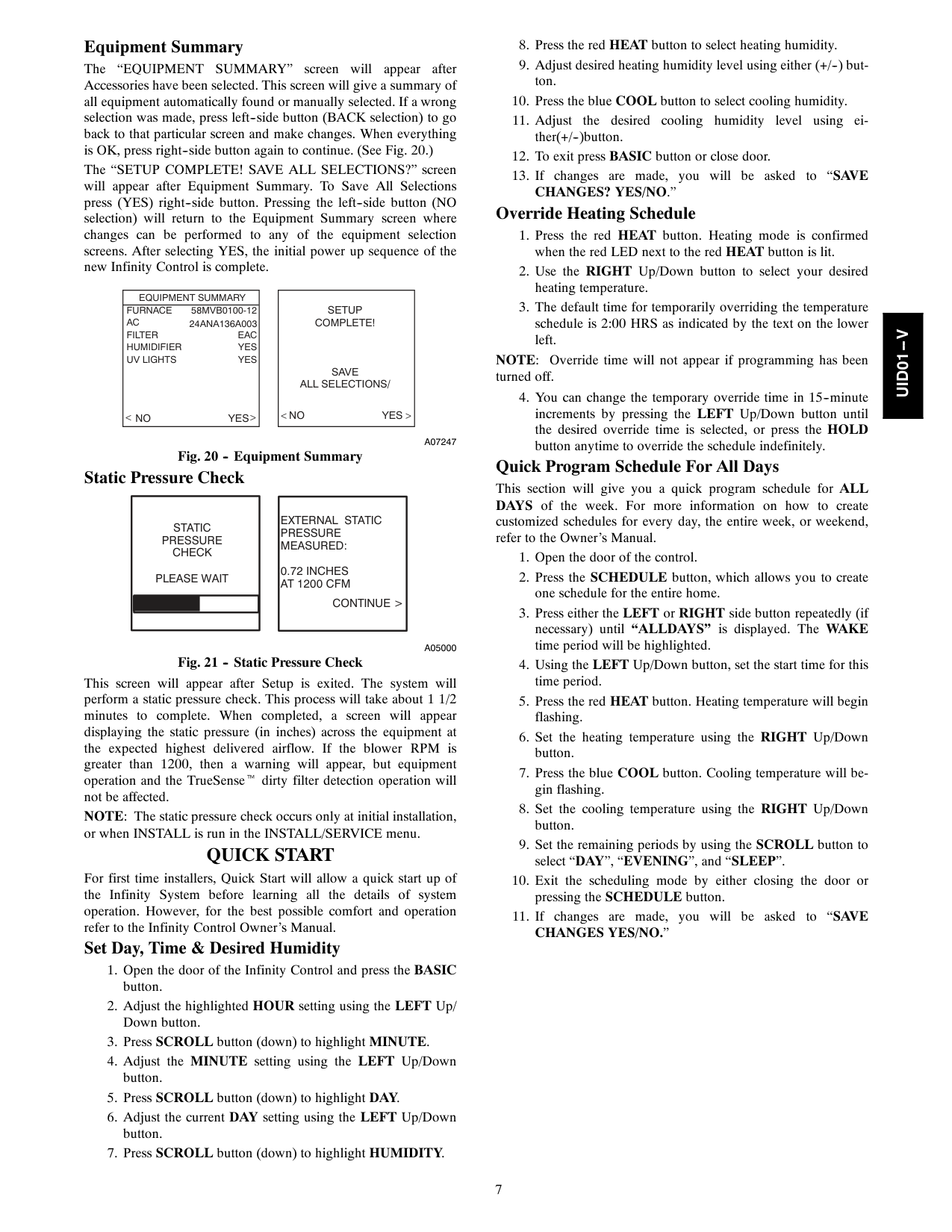
If the variable--speed indoor equipment (furnace or fan coil) cannot be found, the User Interface will display “CANNOT COMMUNICATE WITH INDOOR UNIT”. This MUST be corrected before the initial power up sequence can continue. If indoor unit is found, but outdoor unit is not found, “OUTDOOR UNIT NOT IDENTIFIED” will appear. Proceed to the next section for Outdoor Unit Identification. Selecting Outdoor Unit If there is no communicating outdoor unit, the screen, shown in Fig. 17, will appear. Press either Left or Right Up/Down button to select AC (air conditioner), HP (heat pump), or None (no unit installed). Press right--side button to continue to next screen. If either AC or HP has been selected as the outdoor unit type, the middle screen will appear (see Fig. 17). Press either Left or Right Up/Down button to select appropriate BTU size of outdoor unit, then press right side button to continue. If a NIM (Network Interface Module) is applied for non--communicating two--stage outdoor equipment, select 1 or 2--stage compressor operation, and press right--side button to continue.Outdoor Unit
Not Identified
Select Type: None
None, Ac, Hp
Press +/- To Make
Selection
Continue
Outdoor Unit
Enter Heat Pump
Size
36000 Btu
18000 To 60000 Btu
Press +/- To Make
Selection
Back Continue
Outdoor Unit
Heat Pump
Enter Number Of
SPEEDS, 1 or 2: 1Press +/- To Make
Selection
Back Continue
A03196
Fig. 17 -- Selecting Outdoor Unit NOTE: Range of outdoor unit BTU selection is limited by model number of indoor unit installed. The Infinity Control will not allow an outdoor unit size that is not supported by the installed indoor unit. NOTE: On new system installations, the model and serial number will be recognized and displayed. On any indoor/outdoor board replacements, the equipment will be recognized but the exact model/serial number will not be displayed. Selecting Indoor Evaporator Coil If a furnace is installed with a variable capacity heat pump, a screen will appear to select the installed indoor evaporator coil. This selection is used to adequately calculate refrigerant charge required while in the Heat Pump Charging screens under the Heat Pump Checkout menu. Select “other” for non--Carrier evaporators. Selecting Electric Heater If the equipment is a fan coil, packaged heat pump, or packaged AC and the electric heater is not self--identifying, “ELECTRIC HEATER NOT IDENTIFIED” will appear (see Fig. 18). Press either Left or Right Up/Down button to select appropriate size of electric heater installed, then press right--side button to continue. An asterisks (*) will appear next to electric heater sizes that may cause excessive airflow.Electric Heater
Not Identified
Enter Size: 5 Kw
None, 5,10,15 Kw
Press +/- To Make
Selection
Back Continue
A03197
Fig. 18 -- Selecting Electric HeaterNote:
Range of electric heaters available is limited by model number of the equipment installed. The Infinity Control will not allow an electric heater size that is not supported by the installed equipment. Hydronic Heat Applications The Infinity Control supports 2 types of Hydronic Heat applications:Accessories
Humidifier
Installed? Yes
Press +/- To Make
Selection
Back Continue
Accessories
U.V. Lights
Installed? Yes
Press +/- To Make
Selection
Back Continue
Accessories
Air Filter Type:
Eac
Eac
Media
Media + Eac
Press +/- To Make
Selection
Continue
Air Filter Media Type
Humidifier Installed?
U.V. Lights Installed?
A03198
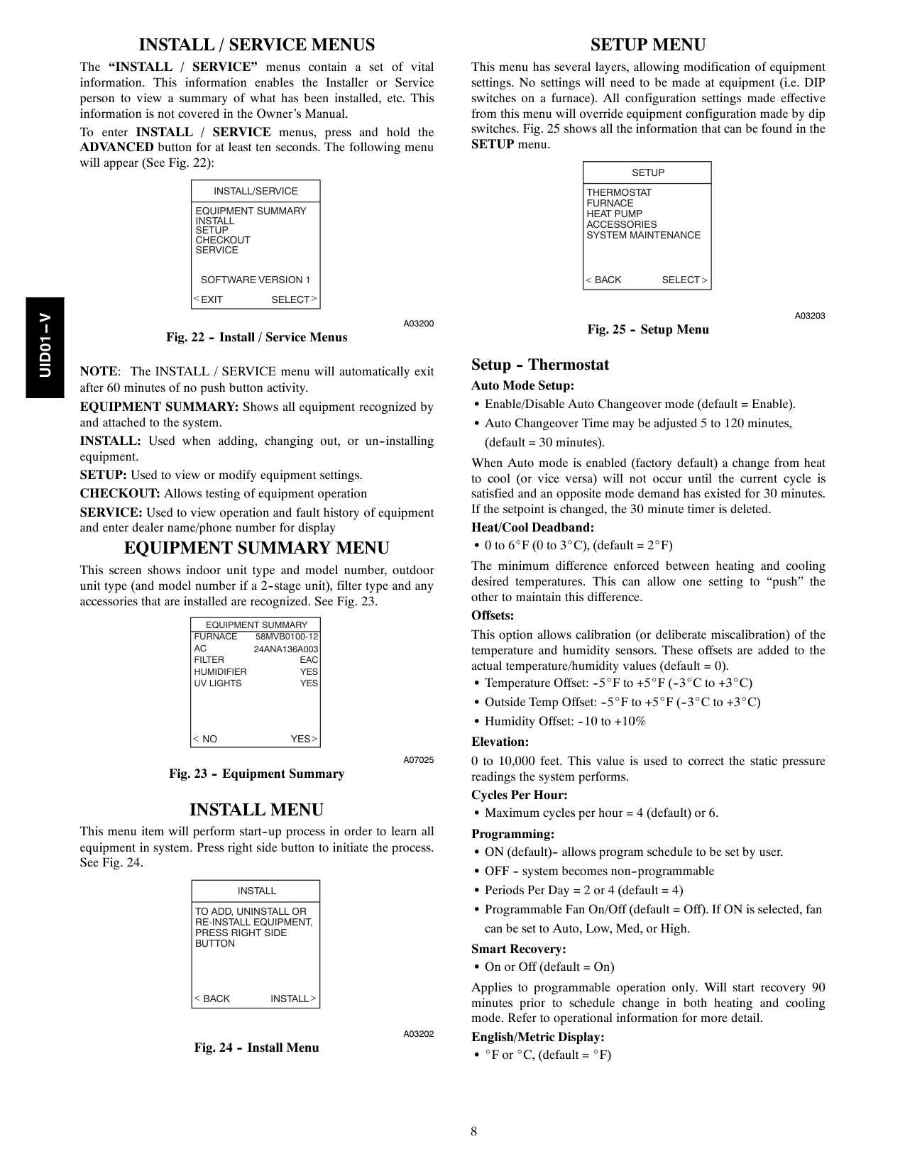
Fig. 19 -- Accessories —UV Lights Air Filter Type This accessory screen will appear first. The installer will need to enter the type of filter (AIR FILTER, ELEC. AIR CLEANER, or PURIFIER). See Table 1 and make a selection using Left or Right Up/Down button, then press right--side button to continue. Table 1 – Filter SelectionInstalled Filter
Menu
Selection
1 inch to 4 inch mediaAir Filter
High voltage EACAir Cleaner
Infinityt Air PurifierAir Purifier
Humidifier Installed This will appear after the Air Filter Type screen. Select whether a humidifier is installed on the system, YES or NO, then press right--side button to continue. UV Lights Installed This screen will appear to select whether UV lights are installed on the system, select YES or NO, then press right--side button to continue.Uid01--V
7 Equipment Summary The
“Equipment
Summary”
screen will appear after Accessories have been selected. This screen will give a summary of all equipment automatically found or manually selected. If a wrong selection was made, press left--side button (BACK selection) to go back to that particular screen and make changes. When everything is OK, press right--side button again to continue. (See Fig. 20.) The “SETUP COMPLETE! SAVE ALL SELECTIONS?” screen will appear after Equipment Summary. To Save All Selections press (YES) right--side button. Pressing the left--side button (NO selection) will return to the Equipment Summary screen where changes can be performed to any of the equipment selection screens. After selecting YES, the initial power up sequence of the new Infinity Control is complete.Equipment Summary
Furnace
58Mvb0100-12
Ac
24Ana136A003
Filter
Eac
Humidifier
Yes
Uv Lights
Yes
No Yes
Setup
Complete!
Save
All Selections/
No Yes
A07247
Fig. 20 -- Equipment Summary Static Pressure CheckStatic
Pressure
Check
Please Wait
External Static
Pressure
Measured:
0.72 Inches
At 1200 Cfm
Continue >
A05000
Fig. 21 -- Static Pressure Check This screen will appear after Setup is exited. The system will perform a static pressure check. This process will take about 1 1/2 minutes to complete. When completed, a screen will appear displaying the static pressure (in inches) across the equipment at the expected highest delivered airflow. If the blower RPM is greater than 1200, then a warning will appear, but equipment operation and the TrueSenset dirty filter detection operation will not be affected. NOTE: The static pressure check occurs only at initial installation, or when INSTALL is run in the INSTALL/SERVICE menu.Quick Start
For first time installers, Quick Start will allow a quick start up of the Infinity System before learning all the details of system operation. However, for the best possible comfort and operation refer to the Infinity Control Owner’s Manual. Set Day, Time & Desired HumidityChanges? Yes/No.”
Override Heating ScheduleChanges Yes/No.”
Uid01--V
8
Install / Service Menus
The “INSTALL / SERVICE” menus contain a set of vital information. This information enables the Installer or Service person to view a summary of what has been installed, etc. This information is not covered in the Owner’s Manual. To enter INSTALL / SERVICE menus, press and hold the ADVANCED button for at least ten seconds. The following menu will appear (See Fig. 22):Install/Service
Equipment Summary
Install
Setup
Checkout
Service
Software Version 1
Exit Select
A03200
Fig. 22 -- Install / Service Menus NOTE: The INSTALL / SERVICE menu will automatically exit after 60 minutes of no push button activity. EQUIPMENT SUMMARY: Shows all equipment recognized by and attached to the system. INSTALL: Used when adding, changing out, or un--installing equipment. SETUP: Used to view or modify equipment settings. CHECKOUT: Allows testing of equipment operation SERVICE: Used to view operation and fault history of equipment and enter dealer name/phone number for displayEquipment Summary Menu
This screen shows indoor unit type and model number, outdoor unit type (and model number if a 2--stage unit), filter type and any accessories that are installed are recognized. See Fig. 23.Equipment Summary
Furnace
58Mvb0100-12
Ac
24Ana136A003
Filter
Eac
Humidifier
Yes
Uv Lights
Yes
No Yes
A07025
Fig. 23 -- Equipment SummaryInstall Menu
This menu item will perform start--up process in order to learn all equipment in system. Press right side button to initiate the process. See Fig. 24.Install
To Add, Uninstall Or
Re-Install Equipment,
Press Right Side
Button
Back Install
A03202
Fig. 24 -- Install MenuSetup Menu
This menu has several layers, allowing modification of equipment settings. No settings will need to be made at equipment (i.e. DIP switches on a furnace). All configuration settings made effective from this menu will override equipment configuration made by dip switches. Fig. 25 shows all the information that can be found in the SETUP menu.Setup
Thermostat
Furnace
Heat Pump
Accessories
System Maintenance
Back Select
A03203
Fig. 25 -- Setup Menu Setup -- Thermostat Auto Mode Setup: S Enable/Disable Auto Changeover mode (default = Enable). S Auto Changeover Time may be adjusted 5 to 120 minutes, (default = 30 minutes). When Auto mode is enabled (factory default) a change from heat to cool (or vice versa) will not occur until the current cycle is satisfied and an opposite mode demand has existed for 30 minutes. If the setpoint is changed, the 30 minute timer is deleted. Heat/Cool Deadband: S 0 to 6_F (0 to 3_C), (default = 2_F) The minimum difference enforced between heating and cooling desired temperatures. This can allow one setting to “push” the other to maintain this difference. Offsets: This option allows calibration (or deliberate miscalibration) of the temperature and humidity sensors. These offsets are added to the actual temperature/humidity values (default = 0). S Temperature Offset: --5_F to +5_F (--3_C to +3_C) S Outside Temp Offset: --5_F to +5_F (--3_C to +3_C) S Humidity Offset: --10 to +10% Elevation: 0 to 10,000 feet. This value is used to correct the static pressure readings the system performs. Cycles Per Hour: S Maximum cycles per hour = 4 (default) or 6. Programming: S ON (default)-- allows program schedule to be set by user. S OFF -- system becomes non--programmable S Periods Per Day = 2 or 4 (default = 4) S Programmable Fan On/Off (default = Off). If ON is selected, fan can be set to Auto, Low, Med, or High. Smart Recovery: S On or Off (default = On) Applies to programmable operation only. Will start recovery 90 minutes prior to schedule change in both heating and cooling mode. Refer to operational information for more detail. English/Metric Display: S _F or _C, (default = _F)Uid01--V
9 Reset Factory Defaults: Program Schedule: S Yes/No to reset back to Energy Star default Time and Temp schedules. User Settings: S Yes/No to reset the user settings in the Advanced Setup to factory default settings. Install Settings: S Yes/No to reset install settings in Install/Service menus to factory default settings. Last 10 System Events: S Yes/No to reset last 10 events under Service Info menu. Setup -- Furnace Upon a first time start--up of the Infinity Control, the furnace DIP switch settings will be copied to the furnace setup menu. Any changes can then be made from the Infinity Control. Furnace Airflow: S COMFORT (default)
S Efficiency
Selects the airflow of the furnace when heating. EFFICIENCY is the airflow used to meet specified ratings, COMFORT is a decreased airflow used to increase the output air temperature and provide increased comfort. Cooling Airflow: S COMFORT (default) -- cooling airflow is varied depending on humidity and temperature demands settings. This selection enables the full dehumidify and comfort capabilities of the system. When COMFORT is not selected, the unit will not run reduced airflows for dehumidification. S EFF 325 -- fixed airflow used to achieve specified ratings -- no dehumidification airflow reduction. This is nominally 325 CFM/ton, but will vary if a 2--stage outdoor unit is used. S EFF 350 -- fixed airflow used to achieve specified ratings -- no dehumidification airflow reduction. This is nominally 350 CFM/ton, but will vary if a 2--stage outdoor unit is used. S MAXIMUM -- 400 CFM/ton. No dehumidification airflow reduction. S QUIET-- minimum cooling airflow that the system can safely run (typically 300 CFM/ton). Use this setting if duct noise is a severe problem. Note that duct sweating in high humidity environments could be an issue. Heat Pump Heating: S COMFORT (default) Heat Pump airflow is varied depending on outdoor temperature to maximize comfort. S EFF 325 -- Fixed airflow used to achieve specified ratings . This is nominally 325 CFM/ton, but will vary if a 2--stage outdoor unit is used. S EFF 350 -- Fixed airflow used to achieve specified ratings . This is nominally 350 CFM/ton, but will vary if a 2--stage outdoor unit is used. S MAXIMUM -- 400 CFM/ton. Heat Pump Cooling: S COMFORT (default) -- cooling airflow is varied depending on humidity and temperature demands settings. This selection enables the full dehumidify and comfort capabilities of the system. When COMFORT is not selected, the unit will not run reduced airflows for dehumidification. S EFF 325 -- fixed airflow used to achieve specified ratings -- no dehumidification airflow reduction. This is nominally 325 CFM/ton, but will vary if a 2--stage outdoor unit is used. S EFF 350 -- fixed airflow used to achieve specified ratings -- no dehumidification airflow reduction. This is nominally 350 CFM/ton, but will vary if a 2--stage outdoor unit is used. S MAXIMUM -- 400 CFM/ton. No dehumidification airflow reduction. S QUIET-- minimum cooling airflow that the system can safely run (typically 300 CFM/ton). Use this setting if duct noise is a severe problem. Note that duct sweating in high humidity environments could be an issue. Dehum Airflow: S NORMAL (factory default) -- When equipment is running to dehumidify, the airflow is allowed to adjust to a minimum to satisfy the dehumidification call. S HIGH -- Minimum airflow during the dehumidify mode is increased to reduce duct and register sweating. Low Heat RiseS On
S OFF (default) Set to ON if the system contains a bypass humidifier. The ON setting will increase the furnace low heat airflow. Staging S SYSTEM (default)S Low
S Low--Med
S Low--High
S Medium
S Med--High
S High
S Furnace
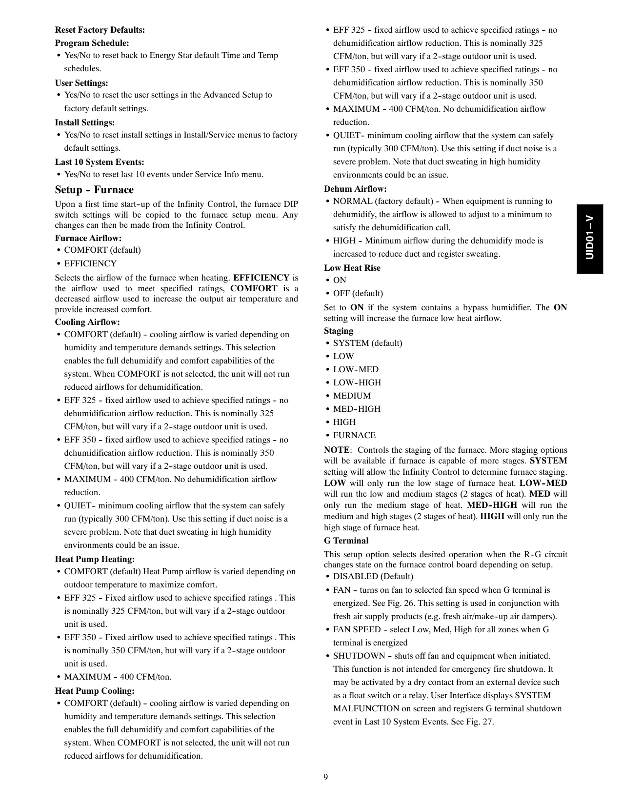
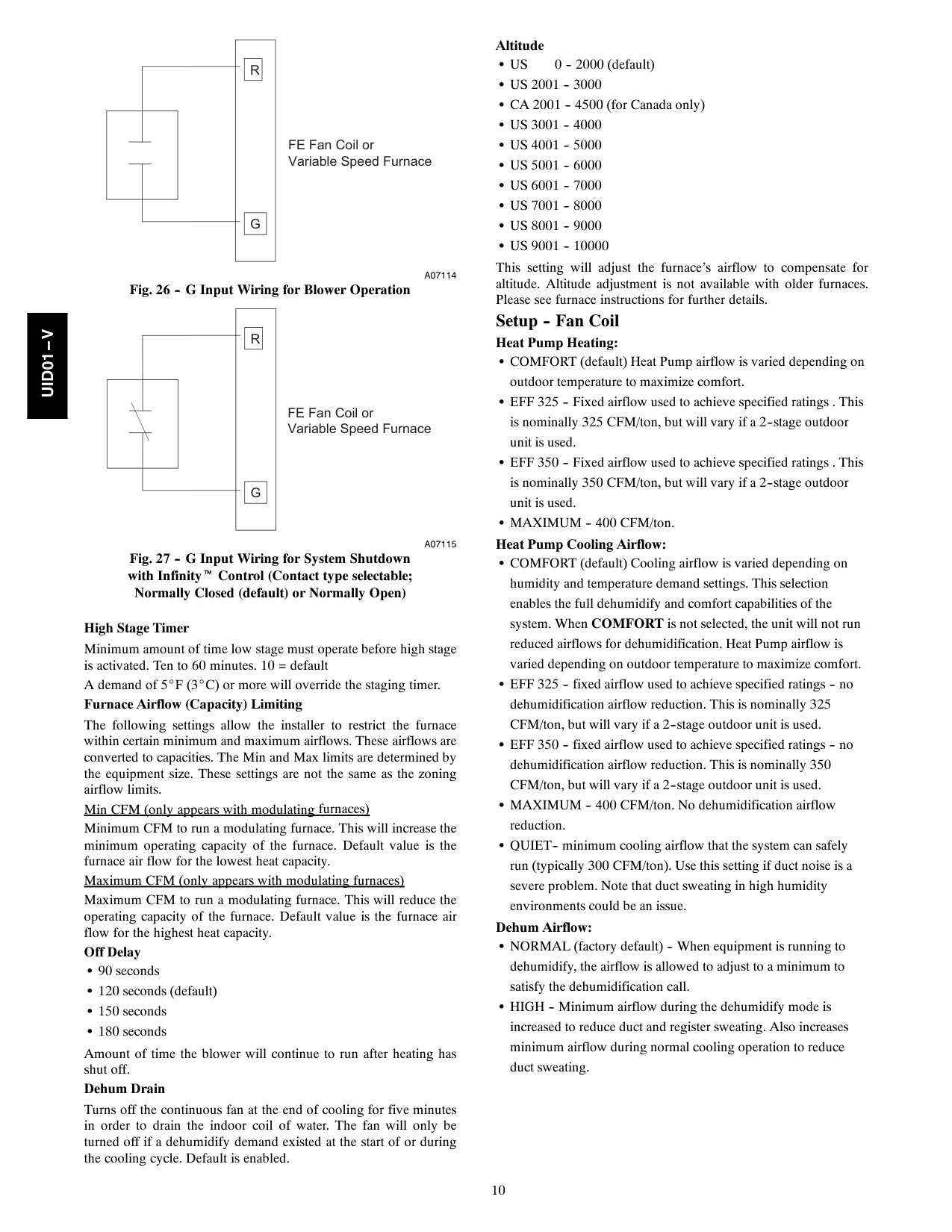
NOTE: Controls the staging of the furnace. More staging options will be available if furnace is capable of more stages. SYSTEM setting will allow the Infinity Control to determine furnace staging. LOW will only run the low stage of furnace heat. LOW--MED will run the low and medium stages (2 stages of heat). MED will only run the medium stage of heat. MED--HIGH will run the medium and high stages (2 stages of heat). HIGH will only run the high stage of furnace heat. G Terminal This setup option selects desired operation when the R--G circuit changes state on the furnace control board depending on setup. S DISABLED (Default) S FAN -- turns on fan to selected fan speed when G terminal is energized. See Fig. 26. This setting is used in conjunction with fresh air supply products (e.g. fresh air/make--up air dampers). S FAN SPEED -- select Low, Med, High for all zones when G terminal is energized S SHUTDOWN -- shuts off fan and equipment when initiated. This function is not intended for emergency fire shutdown. It may be activated by a dry contact from an external device such as a float switch or a relay. User Interface displays SYSTEM MALFUNCTION on screen and registers G terminal shutdown event in Last 10 System Events. See Fig. 27.Uid01--V
10
R
G
FE Fan Coil or Variable Speed FurnaceA07114
Fig. 26 -- G Input Wiring for Blower OperationR
G
FE Fan Coil or Variable Speed FurnaceA07115
Fig. 27 -- G Input Wiring for System Shutdown with Infinityt Control (Contact type selectable; Normally Closed (default) or Normally Open) High Stage Timer Minimum amount of time low stage must operate before high stage is activated. Ten to 60 minutes. 10 = default A demand of 5_F (3_C) or more will override the staging timer. Furnace Airflow (Capacity) Limiting The following settings allow the installer to restrict the furnace within certain minimum and maximum airflows. These airflows are converted to capacities. The Min and Max limits are determined by the equipment size. These settings are not the same as the zoning airflow limits. Min CFM (only appears with modulating furnaces) Minimum CFM to run a modulating furnace. This will increase the minimum operating capacity of the furnace. Default value is the furnace air flow for the lowest heat capacity. Maximum CFM (only appears with modulating furnaces) Maximum CFM to run a modulating furnace. This will reduce the operating capacity of the furnace. Default value is the furnace air flow for the highest heat capacity. Off Delay S 90 seconds S 120 seconds (default) S 150 seconds S 180 seconds Amount of time the blower will continue to run after heating has shut off. Dehum Drain Turns off the continuous fan at the end of cooling for five minutes in order to drain the indoor coil of water. The fan will only be turned off if a dehumidify demand existed at the start of or during the cooling cycle. Default is enabled. AltitudeS Us
0 -- 2000 (default)S Us 2001 -- 3000
S CA 2001 -- 4500 (for Canada only)S Us 3001 -- 4000
S Us 4001 -- 5000
S Us 5001 -- 6000
S Us 6001 -- 7000
S Us 7001 -- 8000
S Us 8001 -- 9000
S Us 9001 -- 10000
This setting will adjust the furnace’s airflow to compensate for altitude. Altitude adjustment is not available with older furnaces. Please see furnace instructions for further details. Setup -- Fan Coil Heat Pump Heating: S COMFORT (default) Heat Pump airflow is varied depending on outdoor temperature to maximize comfort. S EFF 325 -- Fixed airflow used to achieve specified ratings . This is nominally 325 CFM/ton, but will vary if a 2--stage outdoor unit is used. S EFF 350 -- Fixed airflow used to achieve specified ratings . This is nominally 350 CFM/ton, but will vary if a 2--stage outdoor unit is used. S MAXIMUM -- 400 CFM/ton. Heat Pump Cooling Airflow: S COMFORT (default) Cooling airflow is varied depending on humidity and temperature demand settings. This selection enables the full dehumidify and comfort capabilities of the system. When COMFORT is not selected, the unit will not run reduced airflows for dehumidification. Heat Pump airflow is varied depending on outdoor temperature to maximize comfort. S EFF 325 -- fixed airflow used to achieve specified ratings -- no dehumidification airflow reduction. This is nominally 325 CFM/ton, but will vary if a 2--stage outdoor unit is used. S EFF 350 -- fixed airflow used to achieve specified ratings -- no dehumidification airflow reduction. This is nominally 350 CFM/ton, but will vary if a 2--stage outdoor unit is used. S MAXIMUM -- 400 CFM/ton. No dehumidification airflow reduction. S QUIET-- minimum cooling airflow that the system can safely run (typically 300 CFM/ton). Use this setting if duct noise is a severe problem. Note that duct sweating in high humidity environments could be an issue. Dehum Airflow: S NORMAL (factory default) -- When equipment is running to dehumidify, the airflow is allowed to adjust to a minimum to satisfy the dehumidification call. S HIGH -- Minimum airflow during the dehumidify mode is increased to reduce duct and register sweating. Also increases minimum airflow during normal cooling operation to reduce duct sweating.Uid01--V
11 Heater Size: S (choices dependent upon fan coil model) This will show the heater size entered during the start--up process. This value can be changed to another value (limited by the model number of the fan coil). If the electric heater is self--identifying, this value is not shown. Elect Heat Lockout S NONE (default) S +5 to 55_F (--15 to 13_C) Outside temperature above which the electric heat will not operate except for defrost. G Terminal This setup option selects desired operation when the R--G circuit changes state on the fan coil control board depending on setup. S DISABLED (Default) S FAN -- turns on fan to selected fan speed when G terminal is energized. See Fig. 26. This setting is used in conjunction with fresh air supply products (e.g. fresh air make--up air dampers). S FAN SPEED -- select Low, Med, High for all zones when G terminal is energized S SHUTDOWN -- shuts off fan and equipment when initiated. This function is not intended for emergency fire shutdown. It may be activated by a dry contact from an external device such as a float switch or a relay. User selects whether the contact is NC -- normally closed (default) or NO -- normally open. User Interface displays SYSTEM MALFUNCTION on screen and registers G terminal shutdown event in Last 10 System Events. See Fig. 27. Dehum Drain Turns off the continuous fan at the end of cooling for five minutes in order to drain the indoor coil of water. The fan will only be turned off if a dehumidify demand existed at the start of or during the cooling cycle. Default is enabled. Reheat Dehum Enables electric heat to be used while Cool to Dehumidify is running. This will allow the Cool to Dehumidify function to run much longer, greatly improving humidity control in cooling mode. Accumulated electrical energy used while reheating (in kilowatt--hours) is shown on the Fan Coil Run Hours screen and can be reset there. This is only available with fan coil systems. Setup -- Heat Pump / AC Cooling Lockout: S NONE (default)
S 45_F (7_C)
S 50_F (10_C)
S 55_F (13_C)
Outside temperature below which cooling will not be provided. Low Ambient Cooling: S NO (default)S Yes
Selecting YES will enable the low ambient cooling operation in the outdoor unit. This setting is only available with communicating outdoor units and with Cooling Lockout set to NONE. Low ambient kits are not needed with communicating outdoor units. For detailed sequence of operation, see outdoor unit installation instructions. Entered Size: S (dependent on indoor unit model) Size of the outdoor unit entered during the start--up process. If the outdoor unit is a communicating model, this value will not be shown. This size can be changed here but is limited to sizes that the indoor unit can handle. Defrost Interval: S 30 minutes S 60 minutes S 90 minutes S 120 minutes (default) S Auto--Defrost interval optimized by outdoor control (default for communicating HP) Time interval at which defrost cycles can occur on a heat pump. Lockout Temp: S Off (default) S +5 to 55_F (--15 to 18_C) Locks out the heat pump from operating below the selected outside temperature. Appears with a fan coil only. Must be below any electric lockout temperature in Fan Coil Setup. Quiet Shift S Off (default) Turns on Quiet Shift function in 1--stage or 2--stage communicating heat pumps. High Cool Latch: S NONE (default) S On S 80 to 110_F (27 to 43_C) S DISABLE (disable use of high cool stage) Outside temperature above which only the high stage (of a 2--stage outdoor unit) will run when cooling. High Heat Latch S OFF (default) S On S 20 to 50_F (--7 to 10_C) 2 --stage heat pump runs only high stage heating below a selectable outdoor temperature. Selections from 20 to 50_F (--7 to 10_C) are available in 5_F (3_C) increments. S DISABLE (disable use of high heat stage) Max Heat RPM (Appears with variable capacity heat pump) Clamps the operating speed of the heat pump to this maximum. Used to reduce operating noise while in high heating capacity. Reducing this value will reduce the heating capacity of the heat pump. Heat Pump Airflow (Capacity) Limiting The following settings allow the installer to restrict the heat pump within certain minimum and maximum airflows. These airflows are converted to capacities. The Min and Max limits are determined by the equipment size. Min CFM (only appears with variable capacity heat pump) Minimum CFM to run a variable capacity heat pump. This will increase the minimum operating capacity of the heat pump. Default value is the heat pump air flow for the lowest heat capacity. Maximum CFM (only appears with variable capacity heat pump) Maximum CFM to run a variable capacity heat pump This will reduce the operating capacity of the heat pump. Default value is the heat pump air flow for the highest heat capacity.Uid01--V
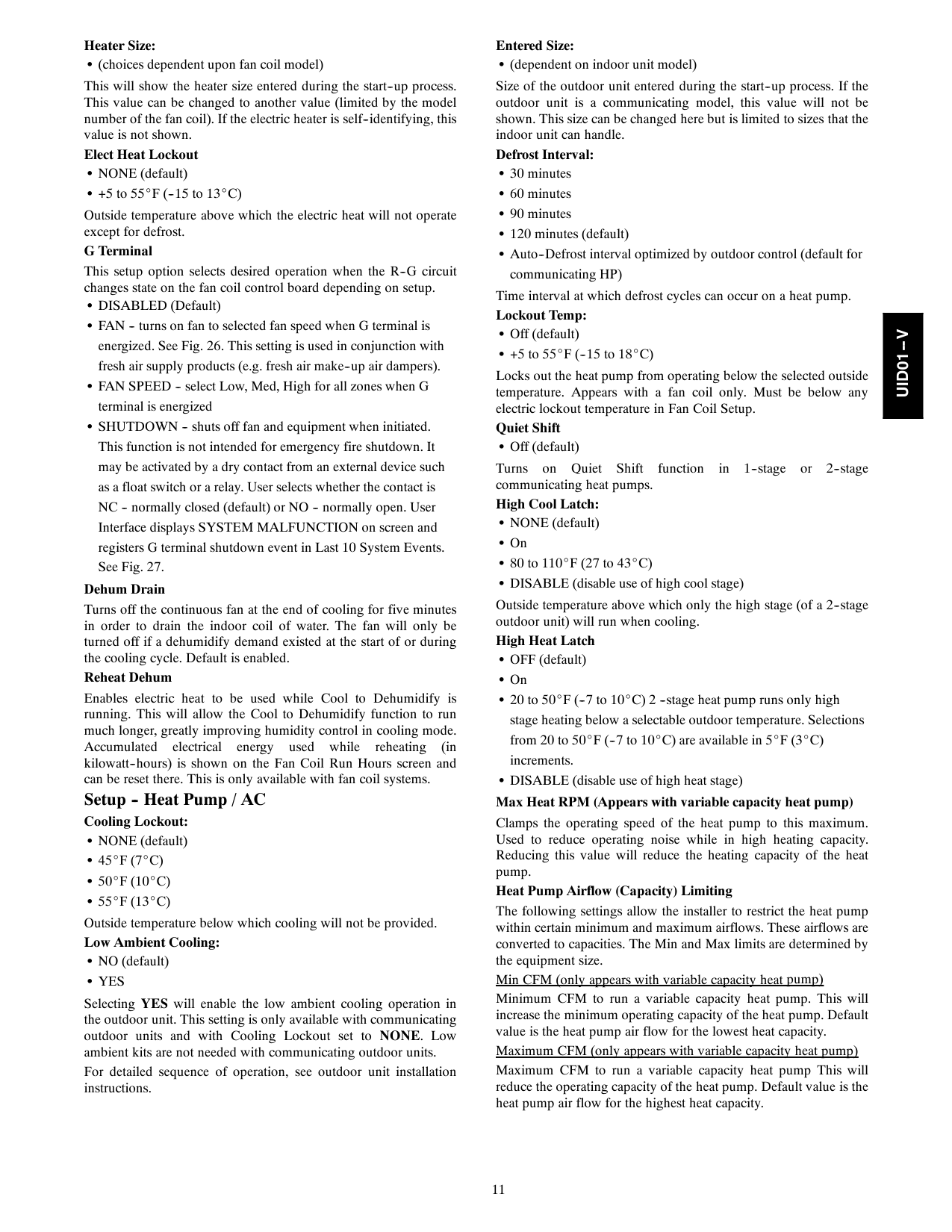
12 Lo Air Multiplier Adjusts the low airflow speed on non--communicating two--stage units. Choose 0.65 for units with a Bristol compressor, choose 0.80 (default) for units with a Copeland scroll compressor. Setup -- Hybrid Heat
Hybrid Heat Setup
Furnace
Lockout:
> 30 F
Heat Pump
Lockout:
< 15 F
Defrost W/Furnace:
Yes
< Back
Hp To Furnace
Stage Time:
15 Min
Outside Lockout Temps
A07030
Fig. 28 -- Hybrid Heat Setup FURNACE LOCKOUT -- Temperature above which only the heat pump will operate, except for defrost. S Default = NONE S Available settings = NONE thru >55_F (13_C) HEAT PUMP LOCKOUT -- Temperature below which only the furnace will operate. S Default = NONE S Available settings = NONE thru <55_F (13_C) DEFROST W/FURNACE -- Choose whether furnace operates during defrost cycle. S Default = YES S Available settings = YES / NO HP TO FURNACE STAGING TIME -- Adjust the minimum amount of time the heat pump will run before furnace will be allowed to run. S Default = 15 MIN S Available settings = 15--60 minutes. If a demand of 5_F (3_C) or greater exists, the timer will be overridden. Setup -- Hydronic HeatHydronic Heat Setup
Airflow:
800 Cfm
Blower On Delay:
30 Sec
Hot Water
Lockout:
> 30 F
Heat Pump
Lockout:
< 45 F
Defrost W/Water:
Yes
Blower Off Delay:
30 Sec
< Back
A07031
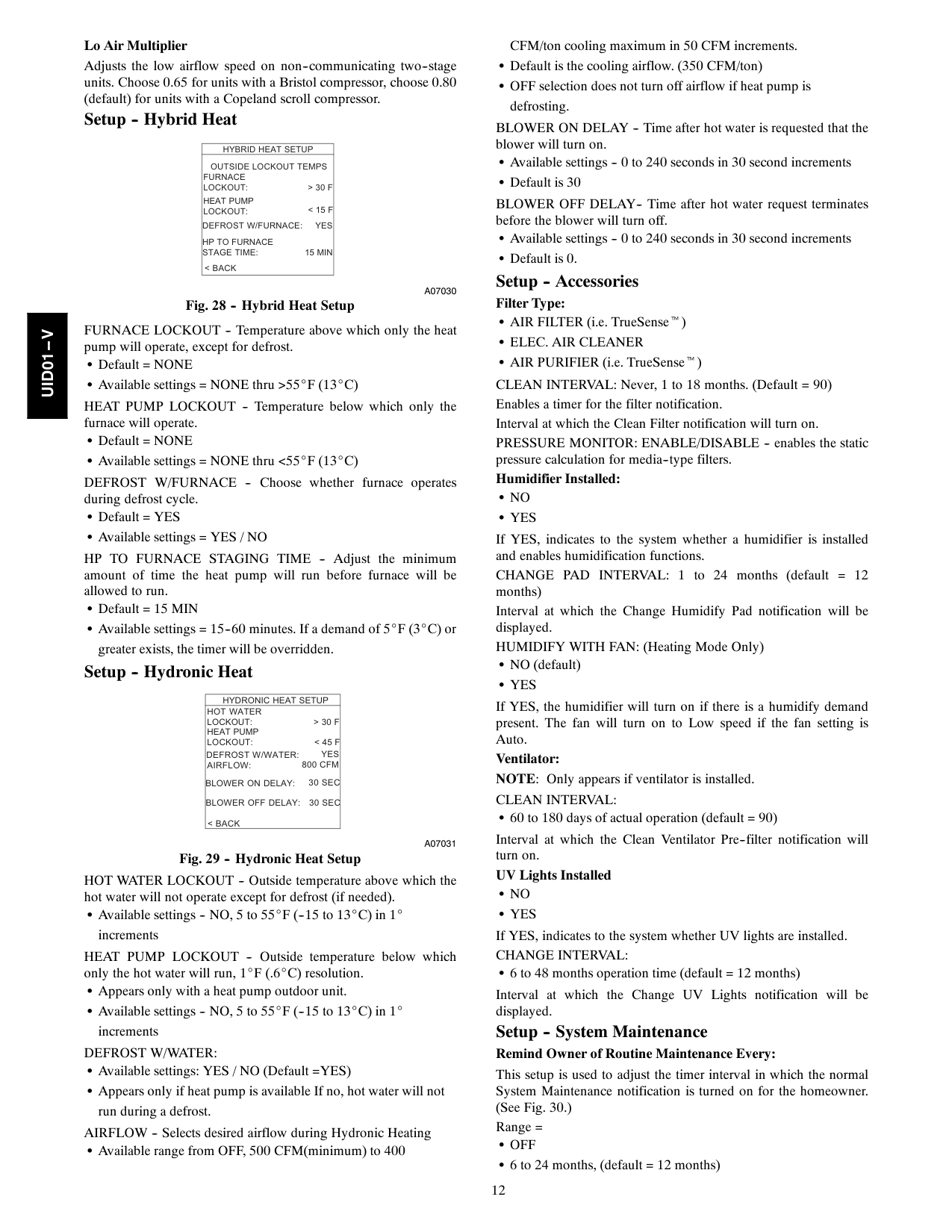
Fig. 29 -- Hydronic Heat Setup HOT WATER LOCKOUT -- Outside temperature above which the hot water will not operate except for defrost (if needed). S Available settings -- NO, 5 to 55_F (--15 to 13_C) in 1_ increments HEAT PUMP LOCKOUT -- Outside temperature below which only the hot water will run, 1_F (.6_C) resolution. S Appears only with a heat pump outdoor unit. S Available settings -- NO, 5 to 55_F (--15 to 13_C) in 1_ incrementsDefrost W/Water:
S Available settings: YES / NO (Default =YES) S Appears only if heat pump is available If no, hot water will not run during a defrost. AIRFLOW -- Selects desired airflow during Hydronic Heating S Available range from OFF, 500 CFM(minimum) to 400 CFM/ton cooling maximum in 50 CFM increments. S Default is the cooling airflow. (350 CFM/ton) S OFF selection does not turn off airflow if heat pump is defrosting. BLOWER ON DELAY -- Time after hot water is requested that the blower will turn on. S Available settings -- 0 to 240 seconds in 30 second increments S Default is 30 BLOWER OFF DELAY-- Time after hot water request terminates before the blower will turn off. S Available settings -- 0 to 240 seconds in 30 second increments S Default is 0. Setup -- Accessories Filter Type: S AIR FILTER (i.e. TrueSenset)S Elec. Air Cleaner
S AIR PURIFIER (i.e. TrueSenset) CLEAN INTERVAL: Never, 1 to 18 months. (Default = 90) Enables a timer for the filter notification. Interval at which the Clean Filter notification will turn on. PRESSURE MONITOR: ENABLE/DISABLE -- enables the static pressure calculation for media--type filters. Humidifier Installed:S No
S Yes
If YES, indicates to the system whether a humidifier is installed and enables humidification functions. CHANGE PAD INTERVAL: 1 to 24 months (default = 12 months) Interval at which the Change Humidify Pad notification will be displayed. HUMIDIFY WITH FAN: (Heating Mode Only) S NO (default)S Yes
If YES, the humidifier will turn on if there is a humidify demand present. The fan will turn on to Low speed if the fan setting is Auto. Ventilator: NOTE: Only appears if ventilator is installed.Clean Interval:
S 60 to 180 days of actual operation (default = 90) Interval at which the Clean Ventilator Pre--filter notification will turn on. UV Lights InstalledS No
S Yes
If YES, indicates to the system whether UV lights are installed.Change Interval:
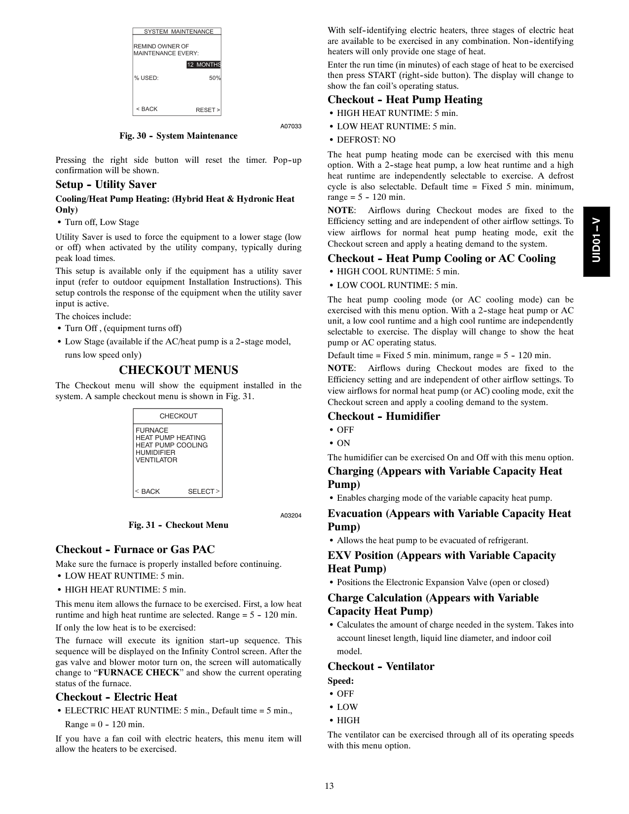
S 6 to 48 months operation time (default = 12 months) Interval at which the Change UV Lights notification will be displayed. Setup -- System Maintenance Remind Owner of Routine Maintenance Every: This setup is used to adjust the timer interval in which the normal System Maintenance notification is turned on for the homeowner. (See Fig. 30.) Range =S Off
S 6 to 24 months, (default = 12 months)Uid01--V
13
System Maintenance
< Back
Remind Owner Of
Maintenance Every:
12 Months
% Used:
50%Reset >
A07033
Fig. 30 -- System Maintenance Pressing the right side button will reset the timer. Pop--up confirmation will be shown. Setup -- Utility Saver Cooling/Heat Pump Heating: (Hybrid Heat & Hydronic Heat Only) S Turn off, Low Stage Utility Saver is used to force the equipment to a lower stage (low or off) when activated by the utility company, typically during peak load times. This setup is available only if the equipment has a utility saver input (refer to outdoor equipment Installation Instructions). This setup controls the response of the equipment when the utility saver input is active. The choices include: S Turn Off , (equipment turns off) S Low Stage (available if the AC/heat pump is a 2--stage model, runs low speed only)Checkout Menus
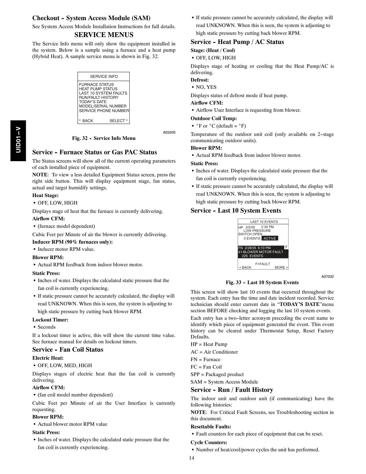
The Checkout menu will show the equipment installed in the system. A sample checkout menu is shown in Fig. 31.Checkout
Furnace
Heat Pump Heating
Heat Pump Cooling
Humidifier
Ventilator
Back Select
A03204
Fig. 31 -- Checkout Menu Checkout -- Furnace or Gas PAC Make sure the furnace is properly installed before continuing. S LOW HEAT RUNTIME: 5 min. S HIGH HEAT RUNTIME: 5 min. This menu item allows the furnace to be exercised. First, a low heat runtime and high heat runtime are selected. Range = 5 -- 120 min. If only the low heat is to be exercised: The furnace will execute its ignition start--up sequence. This sequence will be displayed on the Infinity Control screen. After the gas valve and blower motor turn on, the screen will automatically change to “FURNACE CHECK” and show the current operating status of the furnace. Checkout -- Electric Heat S ELECTRIC HEAT RUNTIME: 5 min., Default time = 5 min., Range = 0 -- 120 min. If you have a fan coil with electric heaters, this menu item will allow the heaters to be exercised. With self--identifying electric heaters, three stages of electric heat are available to be exercised in any combination. Non--identifying heaters will only provide one stage of heat. Enter the run time (in minutes) of each stage of heat to be exercised then press START (right--side button). The display will change to show the fan coil’s operating status. Checkout -- Heat Pump Heating S HIGH HEAT RUNTIME: 5 min. S LOW HEAT RUNTIME: 5 min.S Defrost: No
The heat pump heating mode can be exercised with this menu option. With a 2--stage heat pump, a low heat runtime and a high heat runtime are independently selectable to exercise. A defrost cycle is also selectable. Default time = Fixed 5 min. minimum, range = 5 -- 120 min.Note:
Airflows during Checkout modes are fixed to the Efficiency setting and are independent of other airflow settings. To view airflows for normal heat pump heating mode, exit the Checkout screen and apply a heating demand to the system. Checkout -- Heat Pump Cooling or AC Cooling S HIGH COOL RUNTIME: 5 min. S LOW COOL RUNTIME: 5 min. The heat pump cooling mode (or AC cooling mode) can be exercised with this menu option. With a 2--stage heat pump or AC unit, a low cool runtime and a high cool runtime are independently selectable to exercise. The display will change to show the heat pump or AC operating status. Default time = Fixed 5 min. minimum, range = 5 -- 120 min.Note:
Airflows during Checkout modes are fixed to the Efficiency setting and are independent of other airflow settings. To view airflows for normal heat pump (or AC) cooling mode, exit the Checkout screen and apply a cooling demand to the system. Checkout -- HumidifierS Off
S On
The humidifier can be exercised On and Off with this menu option. Charging (Appears with Variable Capacity Heat Pump) S Enables charging mode of the variable capacity heat pump. Evacuation (Appears with Variable Capacity Heat Pump) S Allows the heat pump to be evacuated of refrigerant. EXV Position (Appears with Variable Capacity Heat Pump) S Positions the Electronic Expansion Valve (open or closed) Charge Calculation (Appears with Variable Capacity Heat Pump) S Calculates the amount of charge needed in the system. Takes into account lineset length, liquid line diameter, and indoor coil model. Checkout -- Ventilator Speed:S Off
S Low
S High
The ventilator can be exercised through all of its operating speeds with this menu option.Uid01--V
14 Checkout -- System Access Module (SAM) See System Access Module Installation Instructions for full details.
Service Menus
The Service Info menu will only show the equipment installed in the system. Below is a sample using a furnace and a heat pump (Hybrid Heat). A sample service menu is shown in Fig. 32.Service Info
Furnace Status
Heat Pump Status
Last 10 System Faults
Run/Fault History
Today’S Date
Model/Serial Number
Service Phone Number
Back Select
A03205
Fig. 32 -- Service Info Menu Service -- Furnace Status or Gas PAC Status The Status screens will show all of the current operating parameters of each installed piece of equipment. NOTE: To view a less detailed Equipment Status screen, press the right side button. This will display equipment stage, fan status, actual and target humidify settings. Heat Stage:S Off, Low, High
Displays stage of heat that the furnace is currently delivering. Airflow CFM: S (furnace model dependent) Cubic Feet per Minute of air the blower is currently delivering. Inducer RPM (90% furnaces only): S Inducer motor RPM value. Blower RPM: S Actual RPM feedback from indoor blower motor. Static Press: S Inches of water. Displays the calculated static pressure that the fan coil is currently experiencing. S If static pressure cannot be accurately calculated, the display will read UNKNOWN. When this is seen, the system is adjusting to high static pressure by cutting back blower RPM. Lockout Timer: S Seconds If a lockout timer is active, this will show the current time value. See furnace manual for details on lockout timers. Service -- Fan Coil Status Electric Heat:S Off, Low, Med, High
Displays stages of electric heat that the fan coil is currently delivering. Airflow CFM: S (fan coil model number dependent) Cubic Feet per Minute of air the User Interface is currently requesting. Blower RPM: S Actual blower motor RPM value Static Press: S Inches of water. Displays the calculated static pressure that the fan coil is currently experiencing. S If static pressure cannot be accurately calculated, the display will read UNKNOWN. When this is seen, the system is adjusting to high static pressure by cutting back blower RPM. Service -- Heat Pump / AC Status Stage: (Heat / Cool)S Off, Low, High
Displays stage of heating or cooling that the Heat Pump/AC is delivering. Defrost:S No, Yes
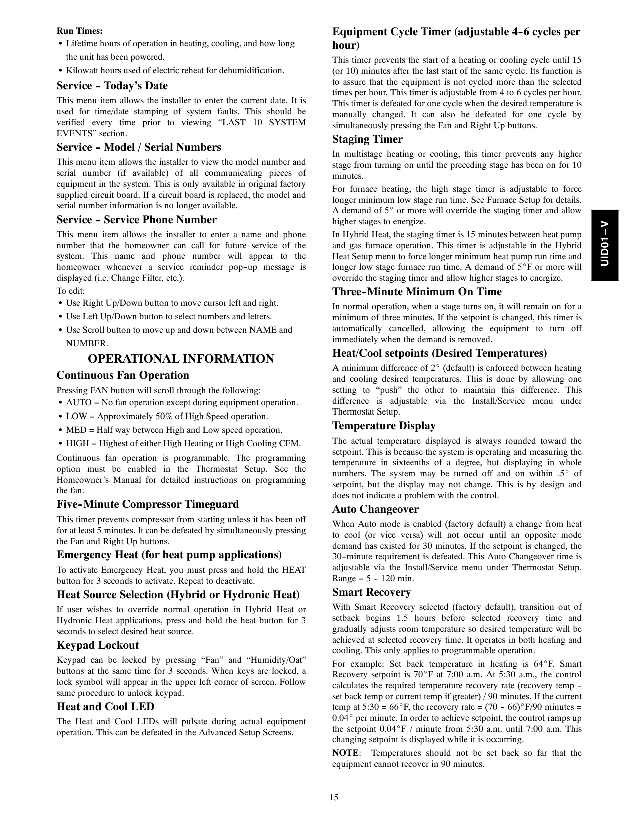
Displays status of defrost mode if heat pump. Airflow CFM: S Airflow User Interface is requesting from blower. Outdoor Coil Temp: S _F or _C (default = _F) Temperature of the outdoor unit coil (only available on 2--stage communicating outdoor units). Blower RPM: S Actual RPM feedback from indoor blower motor. Static Press: S Inches of water. Displays the calculated static pressure that the fan coil is currently experiencing. S If static pressure cannot be accurately calculated, the display will read UNKNOWN. When this is seen, the system is adjusting to high static pressure by cutting back blower RPM. Service -- Last 10 System EventsLast 10 Events
Low Pressure
3/2/052:35 Pm
< Back
More >
Hp
3 Events:
225 Events _
Active
Fn 2/28/05 6:10 Pm
41-Blower Motor Fault
F
Switch Open
F=Fault
A07032
Fig. 33 -- Last 10 System Events This screen will show last 10 events that occurred throughout the system. Each entry has the time and date incident recorded. Service technician should enter current date in “TODAY’S DATE”menu section BEFORE checking and logging the last 10 system events. Each entry has a two--letter acronym preceding the event name to identify which piece of equipment generated the event. This event history can be cleared under Thermostat Setup, Reset Factory Defaults. HP = Heat Pump AC = Air Conditioner FN = Furnace FC = Fan Coil SPP = Packaged product SAM = System Access Module Service -- Run / Fault History The indoor unit and outdoor unit (if communicating) have the following histories: NOTE: For Critical Fault Screens, see Troubleshooting section in this document. Resettable Faults: S Fault counters for each piece of equipment that can be reset. Cycle Counters: S Number of heat/cool/power cycles the unit has performed.Uid01--V
15 Run Times: S Lifetime hours of operation in heating, cooling, and how long the unit has been powered. S Kilowatt hours used of electric reheat for dehumidification. Service -- Today’s Date This menu item allows the installer to enter the current date. It is used for time/date stamping of system faults. This should be verified every time prior to viewing “LAST 10 SYSTEM EVENTS” section. Service -- Model / Serial Numbers This menu item allows the installer to view the model number and serial number (if available) of all communicating pieces of equipment in the system. This is only available in original factory supplied circuit board. If a circuit board is replaced, the model and serial number information is no longer available. Service -- Service Phone Number This menu item allows the installer to enter a name and phone number that the homeowner can call for future service of the system. This name and phone number will appear to the homeowner whenever a service reminder pop--up message is displayed (i.e. Change Filter, etc.). To edit: S Use Right Up/Down button to move cursor left and right. S Use Left Up/Down button to select numbers and letters. S Use Scroll button to move up and down between NAME and
Number.
Operational Information
Continuous Fan Operation Pressing FAN button will scroll through the following: S AUTO = No fan operation except during equipment operation. S LOW = Approximately 50% of High Speed operation. S MED = Half way between High and Low speed operation. S HIGH = Highest of either High Heating or High Cooling CFM. Continuous fan operation is programmable. The programming option must be enabled in the Thermostat Setup. See the Homeowner’s Manual for detailed instructions on programming the fan. Five--Minute Compressor Timeguard This timer prevents compressor from starting unless it has been off for at least 5 minutes. It can be defeated by simultaneously pressing the Fan and Right Up buttons. Emergency Heat (for heat pump applications) To activate Emergency Heat, you must press and hold the HEAT button for 3 seconds to activate. Repeat to deactivate. Heat Source Selection (Hybrid or Hydronic Heat) If user wishes to override normal operation in Hybrid Heat or Hydronic Heat applications, press and hold the heat button for 3 seconds to select desired heat source. Keypad Lockout Keypad can be locked by pressing “Fan” and “Humidity/Oat” buttons at the same time for 3 seconds. When keys are locked, a lock symbol will appear in the upper left corner of screen. Follow same procedure to unlock keypad. Heat and Cool LED The Heat and Cool LEDs will pulsate during actual equipment operation. This can be defeated in the Advanced Setup Screens. Equipment Cycle Timer (adjustable 4--6 cycles per hour) This timer prevents the start of a heating or cooling cycle until 15 (or 10) minutes after the last start of the same cycle. Its function is to assure that the equipment is not cycled more than the selected times per hour. This timer is adjustable from 4 to 6 cycles per hour. This timer is defeated for one cycle when the desired temperature is manually changed. It can also be defeated for one cycle by simultaneously pressing the Fan and Right Up buttons. Staging Timer In multistage heating or cooling, this timer prevents any higher stage from turning on until the preceding stage has been on for 10 minutes. For furnace heating, the high stage timer is adjustable to force longer minimum low stage run time. See Furnace Setup for details. A demand of 5_ or more will override the staging timer and allow higher stages to energize. In Hybrid Heat, the staging timer is 15 minutes between heat pump and gas furnace operation. This timer is adjustable in the Hybrid Heat Setup menu to force longer minimum heat pump run time and longer low stage furnace run time. A demand of 5_F or more will override the staging timer and allow higher stages to energize. Three--Minute Minimum On Time In normal operation, when a stage turns on, it will remain on for a minimum of three minutes. If the setpoint is changed, this timer is automatically cancelled, allowing the equipment to turn off immediately when the demand is removed. Heat/Cool setpoints (Desired Temperatures) A minimum difference of 2_ (default) is enforced between heating and cooling desired temperatures. This is done by allowing one setting to “push” the other to maintain this difference. This difference is adjustable via the Install/Service menu under Thermostat Setup. Temperature Display The actual temperature displayed is always rounded toward the setpoint. This is because the system is operating and measuring the temperature in sixteenths of a degree, but displaying in whole numbers. The system may be turned off and on within .5_ of setpoint, but the display may not change. This is by design and does not indicate a problem with the control. Auto Changeover When Auto mode is enabled (factory default) a change from heat to cool (or vice versa) will not occur until an opposite mode demand has existed for 30 minutes. If the setpoint is changed, the 30--minute requirement is defeated. This Auto Changeover time is adjustable via the Install/Service menu under Thermostat Setup. Range = 5 -- 120 min. Smart Recovery With Smart Recovery selected (factory default), transition out of setback begins 1.5 hours before selected recovery time and gradually adjusts room temperature so desired temperature will be achieved at selected recovery time. It operates in both heating and cooling. This only applies to programmable operation. For example: Set back temperature in heating is 64_F. Smart Recovery setpoint is 70_F at 7:00 a.m. At 5:30 a.m., the control calculates the required temperature recovery rate (recovery temp -- set back temp or current temp if greater) / 90 minutes. If the current temp at 5:30 = 66_F, the recovery rate = (70 -- 66)_F/90 minutes = 0.04_ per minute. In order to achieve setpoint, the control ramps up the setpoint 0.04_F / minute from 5:30 a.m. until 7:00 a.m. This changing setpoint is displayed while it is occurring.Note:
Temperatures should not be set back so far that the equipment cannot recover in 90 minutes.Uid01--V
16 Air Filter If AIR FILTER or AIR PURIFIER is installed in the indoor unit, the system will perform a static pressure check of the system every 24 hours at 1:00 p.m. to monitor filter accumulation (TrueSenset Dirty Filter Detection) or whenever power is applied to the system or the system is transitioned from Off to Cool or Heat modes. The blower will run at a medium airflow for one minute. This system operates by setting a base line static pressure based on the highest airflow the system could run (this could be heat or cool airflow). The measurement is taken at a low airflow and then calculated up to the highest airflow the system could see. Frozen Coil Detection During cooling operation, the User Interface will monitor the static pressure of the system. If the static pressure is increasing dramatically, the User Interface will turn off cooling for up to one hour, record fault in the “Last 10 Events” screen, and run the fan at a reduced airflow. The User Interface will continue to monitor the static pressure. If it is reduced before one hour has elapsed, it will resume cooling operation. After one hour, cooling will be resumed. Dehumidify Operation Once a target cooling humidity setpoint is selected in the Advanced Setup COOLING HUMIDITY screen, two other setup options affect Dehumidify operation:
Cooling
Airflow
andDehumidify.
COOLING AIRFLOW: Setting this to COMFORT or QUIET will enable the system to use low airflow to help dehumidify the space. If duct sweating becomes an issue, setting DEHUM AIRFLOW to HIGH may resolve the problem. DEHUMIDIFY: Located in the Cooling Humidity screen of the Advanced Setup, this option has 2 settings: ON and OFF. If DEHUMIDIFY is set to ON (factory default), then the cooling unit will be allowed to overcool the space up to 3_F (2_C) if the humidity level is above the cooling humidity target setpoint. The amount of over--cooling allowed varies with the dehumidification demand, the cooling demand, and the actual space temperature. More over--cooling is allowed with greater dehumidification demand. When the space temperature is at or above 75_F (24_C) and the dehumidify demand is high, over--cooling up to 3_F (2_C) is allowed. As the space temperature approaches 70_F (21_C), less over--cooling is allowed. At 70_F (21_C) space temperature, no more over--cooling is allowed no matter how great the dehumidify demand. This is done to protect the equipment. If DEHUMIDIFY is set to OFF and Cooling Airflow is set to COMFORT, normal dehumidification mode is enabled. For normal dehumidification, no over--cooling is allowed when the cooling humidity is above the target setpoint, but airflow will be reduced during a normal cooling mode to reduce humidity. The airflow depends on the amount of dehumidify demand. If Cooling Airflow is set toEfficiency
orMaximum,
only Dehumidify (over--cooling to dehumidify) will be performed. Hybrid Heat Setup / Operation Furnace Lockout — (in HYBRID HEAT SETUP menu) is the outside temperature above which the furnace will not run except for defrost (otherwise known as the aux heat lockout). Heat Pump Lockout — (in HYBRID HEAT SETUP) is the outside temperature below which the heat pump will not run (otherwise known as the balance point). These values can be set identical to each other. If they are not identical, the system will stage up and down normally from heat pump to furnace when the outside temperature is between these settings. The User Interface will not allow the heat pump lockout setting to be above the furnace lockout setting. The factory default settings for both of these is NONE (no lockouts). Even though a heat pump lockout temperature may be set, the system will still use the furnace in defrost operation, and may stage back down to heat pump when defrost is completed after a 2 minute delay. Hybrid Heat Defrost — (in HYBRID HEAT SETUP) When the outdoor unit needs a defrost cycle, the furnace will run during defrost regardless of lockout temperature, unless told not to in the Hybrid Heat Setup screen. After defrost, the system may stage down to heat pump after a 2 minute delay. If the room temperature falls below 40_F (4_C) and a furnace lockout is in enabled, the furnace lockout will be overridden to bring on the furnace.Uid01--V
17
Troubleshooting
Please refer to the Troubleshooting Guide available on HVAC Partners for more detail. Infinity Control does not power up.Uid01--V
18