
Ask AI
— answers from the official manualAnswers from the official manual.
Common questions
Common Questions
26 totalWhere can I find the Honeywell e7w thermostat manual and user guide?
The INNCOM e7w Thermostat User Guide (document 31-00302–01) is the complete manual for this battery-powered wireless thermostat. It covers installation, setup, operation, and service mode functions. You can also refer to the INNCOM e7w Thermostat Installation Instructions (document 31-00308) for detailed installation steps. Contact Honeywell at 1.800.543.1999 (US only) or visit inncom.com for technical support and documentation.
How do I install and mount the e7w Battery Thermostat?
The e7w mounts on standard US single-gang, US double-gang, or UK standard gang junction boxes using the provided Smart Wall Mounting Plate. First, attach the plate to the junction box with supplied screws, then insert four AA alkaline batteries into the device, hook the top tabs into the mounting plate depressions, and rotate the housing toward the wall until it snaps into place. Finally, secure with two captive screws at the bottom. Mount the thermostat about 1.5m (5ft.) above the floor in a location with good air circulation, away from drafts, direct sunlight, and other RF sources. (Page 27-28)
What are the battery requirements and how do I replace the batteries in the e7w thermostat?
The e7w requires four AA alkaline batteries (1.5VDC each) that provide 6VDC total power. Insert the batteries into the battery compartment, matching the '+' terminals on the batteries to the '+' symbols in the compartment. When the low battery alarm displays on the screen, replace all four batteries. Use alkaline batteries only and dispose of used batteries according to the WEEE Directive 2012/19/EC instructions. (Page 28-29)
How do I set up the Room ID, PAN ID, and RF Channel during initial setup?
During initialization mode, you must configure three parameters. For Room ID, press MODE and set the high value (0-6), medium value (0-99), and low value (0-99) using UP/DOWN arrows, then press MODE to store. For PAN ID, press MODE and use UP/DOWN arrows to set a value between 0-255, then press FAN to store. For RF Channel, press MODE and use UP/DOWN arrows to set a value between 11-26, then press FAN to store. (Page 30-33)
How do I enter Service Mode on the e7w thermostat?
To enter Service Mode, press and hold the FC key for 5 seconds, then press and release the MODE button, press and release the FAN button, and finally release the FC key. This will display the Parameter and rId value on the screen, allowing you to access advanced configuration options. (Page 34)
What is LEM Mode and how do I enable or disable it on the e7w?
LEM (Limited Energy Management) Mode expands the guest-selectable temperature range by disabling most energy savings algorithms, useful for guests requiring more flexible temperature control. To enable LEM mode, press and hold MODE, press and release FAN, press and release UP arrow, then release MODE—the display will show 'LE.n' confirming a 72-hour LEM mode was activated. To manually disable it, follow the same sequence but press the DOWN arrow instead of UP—the display will show 'nO.r' for normal mode. (Page 35)
Show 20 more questions
How do I bind auxiliary devices like door switches and RF gateways to the e7w thermostat?
How do I verify that devices in my room are communicating with the e7w?
What specifications does the INNCOM e7w thermostat have?
How do I verify door, window, and motion sensor operation on the e7w?
What should I do if the system is operating erratically?
What outdoor wiring protections are required?
Can I use this thermostat in a residential area?
What safety precautions should I take before installing the e7w thermostat?
How should I handle the e7w thermostat to avoid electrostatic discharge damage?
Who should perform the high voltage safety test on the e7w installation?
What is the FCC compliance rating for the e7w thermostat?
Can I install the thermostat near other electrical wiring?
What should an electrician do before starting work on the system?
Can I install the e7w thermostat during an electrical storm?
How far should the thermostat wiring be kept from other electrical components?
Can I place the e7w thermostat wiring in the same conduit as power or lighting circuits?
What should I do if I stand in water while installing the thermostat?
Why is proper grounding important for outdoor wiring used with the e7w?
Is the e7w thermostat susceptible to electrostatic discharge damage?
What happens if the thermostat is not installed according to the instruction manual?
Full Manual
83 pages
U.S. Registered Trademark Copyright © 2020 Honeywell Inc. All Rights Reserved 31-00302–01
INNCOM e7w Thermostat
User Guide
June 2020

INNCOM e7w THERMOSTAT USER GUIDE 31-00302–01 2
Disclaimer This document contains information that is the proprietary and confidential property of INNCOM by Honeywell. By acceptance hereof, each recipient agrees to use the information contained herein only for the purpose anticipated by INNCOM by Honeywell, and not to disclose to others, copy or reproduce, any part hereof without the written consent of INNCOM by Honeywell. The recipient agrees to return this document to INNCOM by Honeywell immediately upon request.
INNCOM e7w THERMOSTAT USER GUIDE
3 31-00302–01
Important Safety Information and Installation Precautions
Read all instructions Failure to follow all instructions may result in equipment damage or a hazardous condition. Read all instructions carefully before installing equipment.
Local codes and practices Always install equipment in accordance with the National Electric Code and in a manner acceptable to the local authority having jurisdiction.
Electrostatic sensitivity This product and its components may be susceptible to electrostatic discharge (ESD). Use appropriate ESD grounding techniques while handling the product. When possible, always handle the product by its non-electrical components.
High voltage safety test Experienced electricians, at first contact, always assume that hazardous voltages may exist in any wiring system. A safety check using a known, reliable voltage measurement or detection device should be made immediately before starting work and when work resumes.
Lightning and high-voltage danger Most electrical injuries involving low-voltage wiring result from sudden, unexpected high voltages on normally low voltage wiring. Low-voltage wiring can carry hazardous high voltages under unsafe conditions. Never install or connect wiring or equipment during electrical storms. Improperly protected wiring can carry a fatal lightning surge for many miles. All outdoor wiring must be equipped with properly grounded and listed signal circuit protectors, which must be installed in compliance with local, applicable codes. Never install wiring or equipment while standing in water.
Wiring and equipment separations All wiring and controllers must be installed to minimize the possibility of accidental contact with other potentially hazardous and disruptive power and lighting wiring. Never place 24VAC or communications wiring near other bare power wires, lightning rods, antennas, transformers, or steam or hot water pipes. Never place wire in any conduit, box, channel, duct or other enclosure containing power or lighting circuits of any type. Always provide adequate separation of communications wiring and other electrical wiring according to code. Keep wiring and controllers at least six feet from large inductive loads (power distribution panels, lighting ballasts, motors, etc.). Failure to follow these guidelines can introduce electrical interference and cause the system to operate erratically.
INNCOM e7w THERMOSTAT USER GUIDE 31-00302–01 4
Warning This equipment has been tested and found to comply with the limits for a class A digital device, pursuant to part 15 of the FCC rules. These limits are designed to provide reasonable protection against harmful interference when the equipment is operated in a commercial environment. This equipment generates, uses, and can radiate radio frequency energy and, if not installed and used in accordance with the instruction manual, may cause harmful interference to radio communications. Operation of this equipment in a residential area is likely to cause harmful interference, in which case the user will be required to correct the interference at his own expense. By using this Honeywell literature, you agree that Honeywell will have no liability for any damages arising out of your use, or modification to, the literature. You will defend and indemnify Honeywell, its affiliates and subsidiaries, from and against any liability, cost, or damages, including attorneys’ fees, arising out of, or resulting from, any modification to the literature by you. The material in this document is for information purposes only. The content and the product it describes are subject to change without notice. Honeywell makes no representations or warranties with respect to this document. In no event shall Honeywell be liable for technical or editorial omissions or mistakes in this document, nor shall it be liable for any damages, direct or incidental, arising out of or related to the use of this document. No part of this document may be reproduced in any form or by any means without prior written permission from Honeywell.
Copyright © 2020 by Honeywell International, Inc. All Rights Reserved. Honeywell | www.INNCOM.com
INNCOM e7w THERMOSTAT USER GUIDE
5 31-00302–01
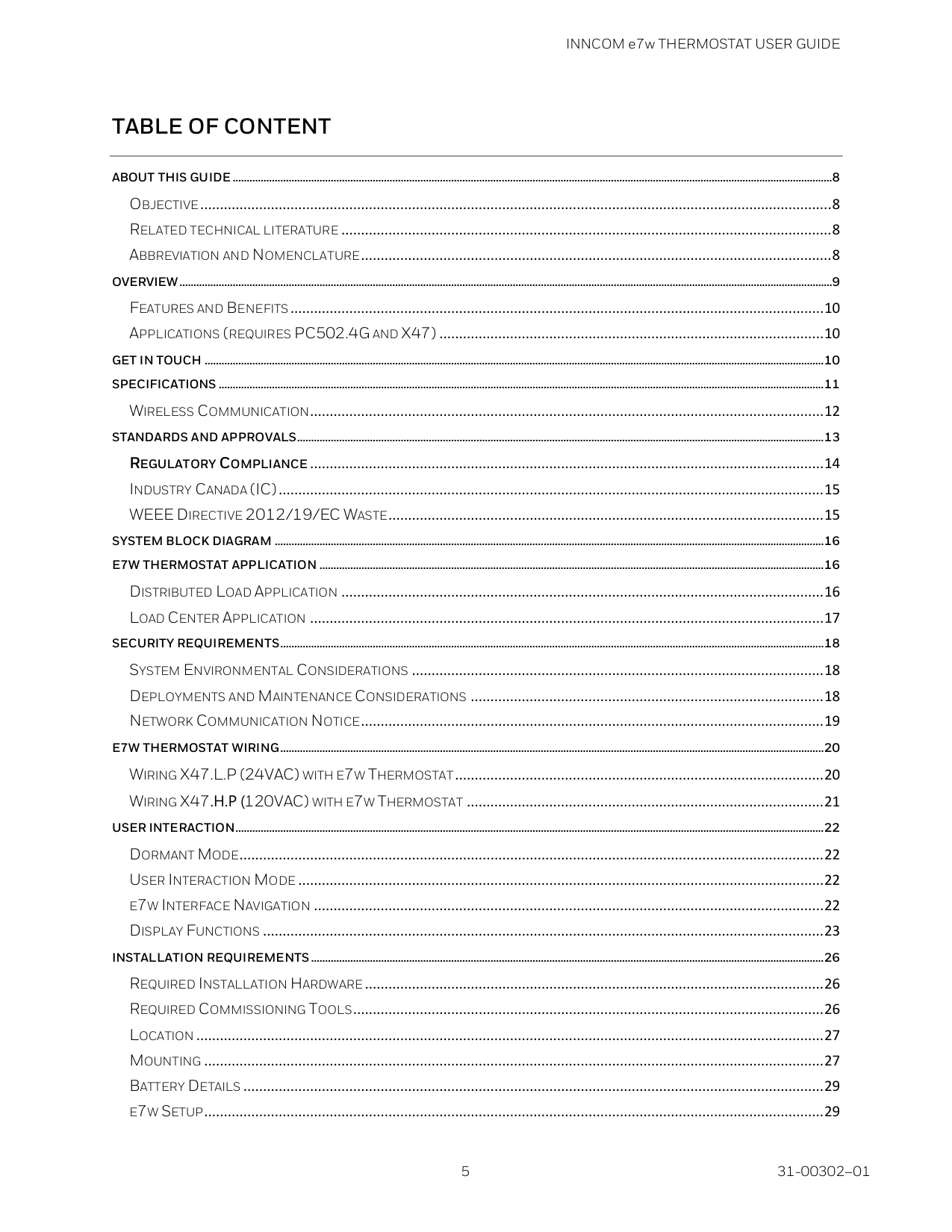
Table Of Content
ABOUT THIS GUIDE ......................................................................................................................................................................................................................8 OBJECTIVE ................................................................................................................................................................. 8 RELATED TECHNICAL LITERATURE ............................................................................................................................. 8 ABBREVIATION AND NOMENCLATURE ........................................................................................................................ 8 OVERVIEW .........................................................................................................................................................................................................................................9 FEATURES AND BENEFITS ........................................................................................................................................ 10 APPLICATIONS (REQUIRES PC502.4G AND X47) .................................................................................................. 10 GET IN TOUCH ............................................................................................................................................................................................................................. 10 SPECIFICATIONS ........................................................................................................................................................................................................................ 11 WIRELESS COMMUNICATION................................................................................................................................... 12 STANDARDS AND APPROVALS............................................................................................................................................................................................ 13 REGULATORY COMPLIANCE ................................................................................................................................... 14 INDUSTRY CANADA (IC) ........................................................................................................................................... 15 WEEE DIRECTIVE 2012/19/EC WASTE ............................................................................................................... 15 SYSTEM BLOCK DIAGRAM .................................................................................................................................................................................................... 16 E7W THERMOSTAT APPLICATION .................................................................................................................................................................................... 16 DISTRIBUTED LOAD APPLICATION ........................................................................................................................... 16 LOAD CENTER APPLICATION ................................................................................................................................... 17 SECURITY REQUIREMENTS.................................................................................................................................................................................................. 18 SYSTEM ENVIRONMENTAL CONSIDERATIONS ......................................................................................................... 18 DEPLOYMENTS AND MAINTENANCE CONSIDERATIONS .......................................................................................... 18 NETWORK COMMUNICATION NOTICE ...................................................................................................................... 19 E7W THERMOSTAT WIRING .................................................................................................................................................................................................. 20 WIRING X47.L.P (24VAC) WITH E7W THERMOSTAT .............................................................................................. 20 WIRING X47.H.P (120VAC) WITH E7W THERMOSTAT ........................................................................................... 21 USER INTERACTION.................................................................................................................................................................................................................. 22 DORMANT MODE..................................................................................................................................................... 22 USER INTERACTION MODE ...................................................................................................................................... 22 E7W INTERFACE NAVIGATION .................................................................................................................................. 22 DISPLAY FUNCTIONS ............................................................................................................................................... 23 INSTALLATION REQUIREMENTS ....................................................................................................................................................................................... 26 REQUIRED INSTALLATION HARDWARE ..................................................................................................................... 26 REQUIRED COMMISSIONING TOOLS ........................................................................................................................ 26 LOCATION ................................................................................................................................................................ 27 MOUNTING .............................................................................................................................................................. 27 BATTERY DETAILS .................................................................................................................................................... 29 E7W SETUP.............................................................................................................................................................. 29
INNCOM e7w THERMOSTAT USER GUIDE 31-00302–01 6
INITIAL SETUP.............................................................................................................................................................................................................................. 30 SETUP ROOM ID ...................................................................................................................................................... 30 SETUP PAN ID ......................................................................................................................................................... 32 SETUP RF CHANNEL ............................................................................................................................................... 32 SERVICE MODE........................................................................................................................................................ 34 VERIFYING HVAC PARTNER ADDRESS (PA) ............................................................................................................ 34 ACTIVATING LEM MODE IN THE E7W HVAC PARTNER USING THE E7W ..................................................................................................... 35 ENABLING LEM MODE ........................................................................................................................................... 35 MANUAL DISABLING LEM MODE ........................................................................................................................... 35 BINDING AUXILIARY DEVICES............................................................................................................................................................................................. 36 BINDING THE RF TO S5 GATEWAY USED BY THE E7W ............................................................................................. 36 BINDING S541.RF DOOR, WINDOW OR BALCONY SWITCHES ................................................................................ 36 VERIFYING IN-ROOM INSTALLED DEVICES .............................................................................................................. 37 VERIFYING ENTRY DOOR REPORTING ...................................................................................................................... 37 VERIFYING GUEST OCCUPANCY REPORTING ........................................................................................................... 38 SERVICE MODE FUNCTIONS ............................................................................................................................................................................................... 39 RID – SETTING E7W ROOM ID (RLD) ...................................................................................................................... 41 PAN – SETTING E7W PAN ID (PAN) ....................................................................................................................... 43 RF – SETTING E7W RF CHANNEL (RF) ................................................................................................................... 43 ADR – TEACHING A DEVICE ADDRESS (ADR) .......................................................................................................... 44 Reverse Binding ............................................................................................................................................... 44 Forward Binding............................................................................................................................................... 45 IO – TEACHING A DEVICE I/O MAP (IO) .................................................................................................................. 46 Reverse Binding ............................................................................................................................................... 47 Forward Binding............................................................................................................................................... 47 REG – CBL32 REGISTRY EDIT (REG) .................................................................................................................... 49 If Group 9 Thermo/HVAC selected as the Gr. (Group) in step 4: ............................................................. 50 If Group 7 Input/Output selected as the Gr. (Group) in step 4: ............................................................... 51 PNG – VERIFYING DEVICE COMMUNICATION (PNG) .............................................................................................. 56 RH – MEASURING ROOM HUMIDITY (RH) .............................................................................................................. 57 RST – RESETTING E7W (RST).................................................................................................................................. 58 WAN – VERIFYING WIDE AREA NETWORK (WAN) ................................................................................................... 58 DOR – VERIFYING DOOR POSITION (DOR) .............................................................................................................. 59 PIR – VERIFYING MOTION SENSOR (PIR) ............................................................................................................... 61 WIN – VERIFYING WINDOW POSITION (WIN) .......................................................................................................... 62 BND – BINDING AUXILIARY DEVICES (BND) ............................................................................................................ 63 VER – VERIFYING E7W VERSION (VER) .................................................................................................................. 65 PRR – REMOTE MOTION SENSOR (PRR) ................................................................................................................ 66 BAU – E7W BATTERY LEVEL (BAU) ......................................................................................................................... 67

INNCOM e7w THERMOSTAT USER GUIDE
7 31-00302–01
SER – SERVICE PARAMETER (SER) ......................................................................................................................... 68 P5C – P5 CHANNEL PARAMETER (P5C) ............................................................................................................... 70 PA – PA PARTNER ADDRESS PARAMETER (PA) ...................................................................................................... 70 PI5 – PROCESS IMAGE VIEWER PARAMETER (PI5) ................................................................................................. 71 E7W – E7W ADDRESS PARAMETER (E7W) ............................................................................................................ 73 OAT – OUTSIDE AIR TEMPERATURE PARAMETER (OAT).......................................................................................... 73 PFT – E7W PIR MOTION SENSOR FILTER (PFT) .................................................................................................... 75 CTR – CONTRACTOR MODE PARAMETER (CTR) ..................................................................................................... 75 BINDING AND TESTING RF LOCKS USING E7W ......................................................................................................................................................... 78 SAFLOK RF LOCKS .................................................................................................................................................. 78 TIMELOX RF LOCKS ................................................................................................................................................ 79 SALTO RF LOCKS .................................................................................................................................................... 80 FIRMWARE UPGRADE .............................................................................................................................................................................................................. 81
INNCOM e7w THERMOSTAT USER GUIDE 31-00302–01 8
About this guide This document is a part of the INNCOM e7w thermostat technical documentation library. Objective This document addresses two audiences • Hotel Administrator or Commissioning Engineer to install and use the INNCOM e7w thermostat end- to-end. • INNCOM engineering personnel tasked to prepare the e7w for service. Related technical literature Literature Number Literature Name 31-00308 INNCOM e7w Thermostat Installation Instructions Abbreviation and Nomenclature Abbreviation Definition
Iras 2.0
Integrated Room Automation System (next generation)Dmn
Deep Mesh NetworkFcu
Fan Coil UnitVac
Volts AC (Alternating Current)Vdc/ Dc
Volts DC (Direct Current)Otw
Over-The-WireBs
British Standard – reference to a 70 x 70mm back boxEta
Serial Communication protocolEms
Energy Management SystemPms
Property Management SystemBms
Building Management SystemLem
Limited Energy Management e7w e7 Wireless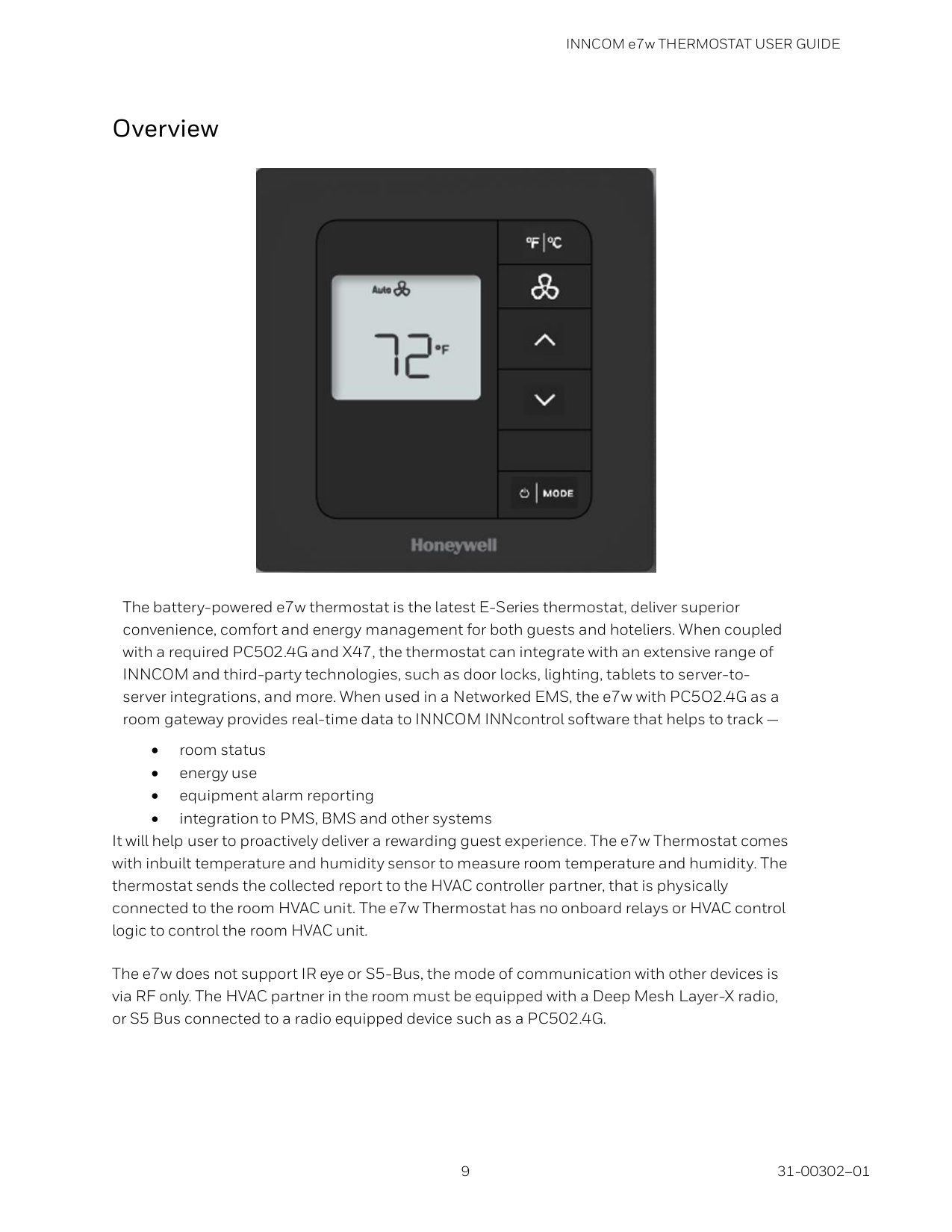
INNCOM e7w THERMOSTAT USER GUIDE
9 31-00302–01
Overview
The battery-powered e7w thermostat is the latest E-Series thermostat, deliver superior convenience, comfort and energy management for both guests and hoteliers. When coupled with a required PC502.4G and X47, the thermostat can integrate with an extensive range of INNCOM and third-party technologies, such as door locks, lighting, tablets to server-to- server integrations, and more. When used in a Networked EMS, the e7w with PC5O2.4G as a room gateway provides real-time data to INNCOM INNcontrol software that helps to track — • room status • energy use • equipment alarm reporting • integration to PMS, BMS and other systems It will help user to proactively deliver a rewarding guest experience. The e7w Thermostat comes with inbuilt temperature and humidity sensor to measure room temperature and humidity. The thermostat sends the collected report to the HVAC controller partner, that is physically connected to the room HVAC unit. The e7w Thermostat has no onboard relays or HVAC control logic to control the room HVAC unit. The e7w does not support IR eye or S5-Bus, the mode of communication with other devices is via RF only. The HVAC partner in the room must be equipped with a Deep Mesh Layer-X radio, or S5 Bus connected to a radio equipped device such as a PC502.4G.
INNCOM e7w THERMOSTAT USER GUIDE 31-00302–01 10
Features and Benefits • Battery operated wireless communication integrated with on-board motion, temperature, and humidity sensors. • Provides standalone or networked energy management. • Compatible with most HVAC systems found in hotel guestrooms, assisted living facilities, student housing, and more. • Provides real-time data to INNcontrol 5/ INNcontrol 3 for reporting, monitoring, central energy control, and diagnostics. • A user-friendly interactive design with easy to read keypad. • Supports standard mounting junction boxes (US single-gang, US double-gang and UK standard gang). Applications (requires PC502.4G and X47) • Basic Thermostat. Traditional HVAC control. • Basic EMS: Optimizes in-room energy based on occupancy detection via a built-in (and/or remote) motion sensor. • Advanced EMS: Optimizes in-room energy based on occupancy detection via a motion sensor and a door sensor or a lock integration. • Networked EMS: Optimizes in-room energy by occupancy and room status via centrally- monitored and optimized INNcontrol 5 and INNcontrol 3 software. • e7w thermostat can be used as commissioning tool. Get In Touch For 24 x7x 365 Technical Support: Contact Toll free number 1.800.543.1999, (US only) Visit us at inncom.com Technical support e-mail at [email protected] Parts Orders available Monday to Friday from 8:00 AM to 5:00 PM, Eastern Time Tel: +1.800.543.1999
INNCOM e7w THERMOSTAT USER GUIDE
11 31-00302–01
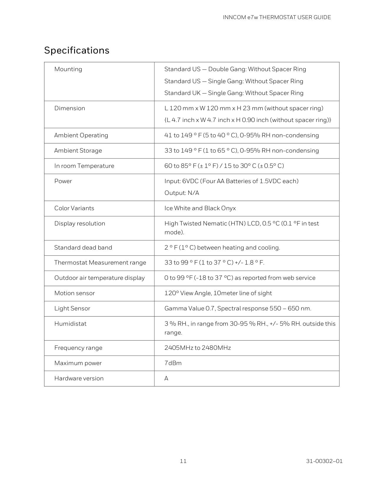
Specifications Mounting Standard US — Double Gang: Without Spacer Ring Standard US — Single Gang: Without Spacer Ring Standard UK — Single Gang: Without Spacer Ring Dimension L 120 mm x W 120 mm x H 23 mm (without spacer ring) {L 4.7 inch x W 4.7 inch x H 0.90 inch (without spacer ring)} Ambient Operating 41 to 149 ° F (5 to 40 ° C), 0-95% RH non-condensing Ambient Storage 33 to 149 ° F (1 to 65 ° C), 0-95% RH non-condensing In room Temperature 60 to 85° F (± 1° F) / 15 to 30° C (± 0.5° C) Power Input: 6VDC (Four AA Batteries of 1.5VDC each) Output: N/A Color Variants Ice White and Black Onyx Display resolution High Twisted Nematic (HTN) LCD, 0.5 °C (0.1 °F in test mode). Standard dead band 2 ° F (1° C) between heating and cooling. Thermostat Measurement range 33 to 99 ° F (1 to 37 ° C) +/- 1.8 ° F. Outdoor air temperature display 0 to 99 °F (-18 to 37 °C) as reported from web service Motion sensor 120° View Angle, 10meter line of sight Light Sensor Gamma Value 0.7, Spectral response 550 – 650 nm. Humidistat 3 % RH., in range from 30-95 % RH., +/- 5% RH. outside this range. Frequency range 2405MHz to 2480MHz Maximum power 7dBm Hardware version
A
INNCOM e7w THERMOSTAT USER GUIDE 31-00302–01 12
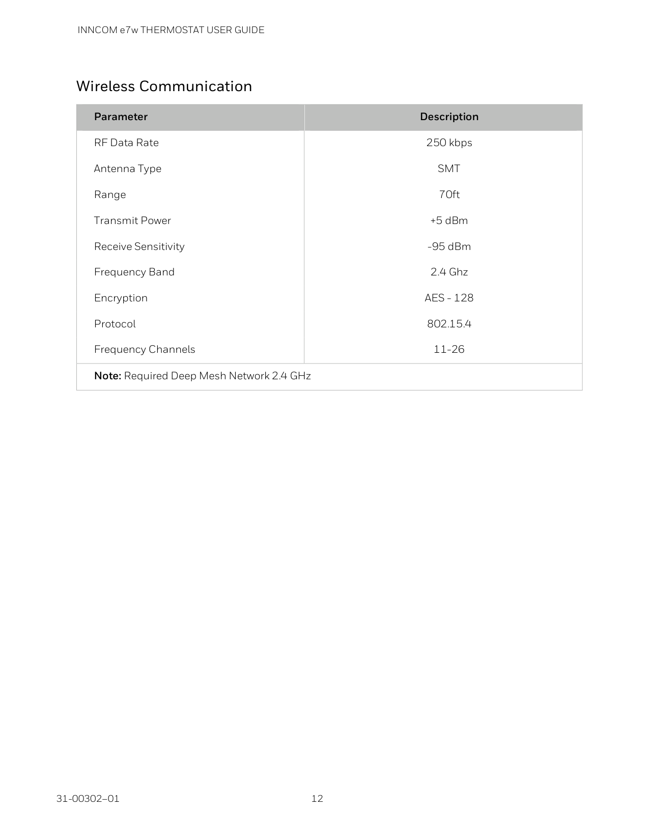
Wireless Communication Parameter Description RF Data Rate 250 kbps Antenna Type
Smt
Range 70ft Transmit Power +5 dBm Receive Sensitivity -95 dBm Frequency Band 2.4 Ghz EncryptionAes - 128
Protocol 802.15.4 Frequency Channels 11-26 Note: Required Deep Mesh Network 2.4 GHz
INNCOM e7w THERMOSTAT USER GUIDE
13 31-00302–01
Standards and Approvals
En
• Product Standard − EN 60730-1:2011 and EN 60730-2-9:2010 (covers EMC and LVD Safety requirements). • EMC Standard − ETSI 301489-1 V2.2.1, ETSI 301 489-17 V 3.2.0. • EMC Standard EN 55032 − Radiated RF Emissions.Ul (Iec)
• UL 60730-1, 5th edition and UL 60730-2-9, 4th edition. • IEC and EN EMC standards: o EU RoHs: EN 50581:2012 per EU RoHS Directive 2011/65/EU, o EN 50581:2012 per EU RoHS Directive 2011/65/EU. o IEC60417, No.5957. For indoor use only. o Class III equipment per IEC 61140. • Radio – FCC Part 15 Subpart C (15.249), Industry Canada RSS-210 Issue 9:2016 and RSS-GEN Issue 4:2014. • IPx1 protection. • Pollution Degree 2. • Type 1 action, operating control.Csa
• CSA (IEC Based), Note 1: on standards, Note 2:on aspects impacted by transition • CAN/CSA E60730-1, 5th edition • CAN/CSA E60730-2-9, 4th edition
INNCOM e7w THERMOSTAT USER GUIDE 31-00302–01 14
Note
We have a choice of the IEC based path or the updated version of Spec. 24. Considerations: • CSA C22.2 No. 24-93 has been in place but will not be allowed from Jan. 1, 2017. It is being replaced with CSA C22.2 No. 24-2015 as of that date (Environmental Requirements). • CSA C22.2 No. 24-2015 references CSA C22.2 No. 0.8 for electronic controls with safety functions, functional safety and EMC instead of 60730-1 Annex H. • According to CSA, the deviations for Canada added to CAN/CSA 60730-1 and 60730-2-9 make this choice equivalent to use of CSA C22.2 No. 24-2015. Regulatory Compliance UL Listing This device meets UL 60730-2-9, CAN/CSA-E60730-2-9 Standard for Automatic Electrical Controls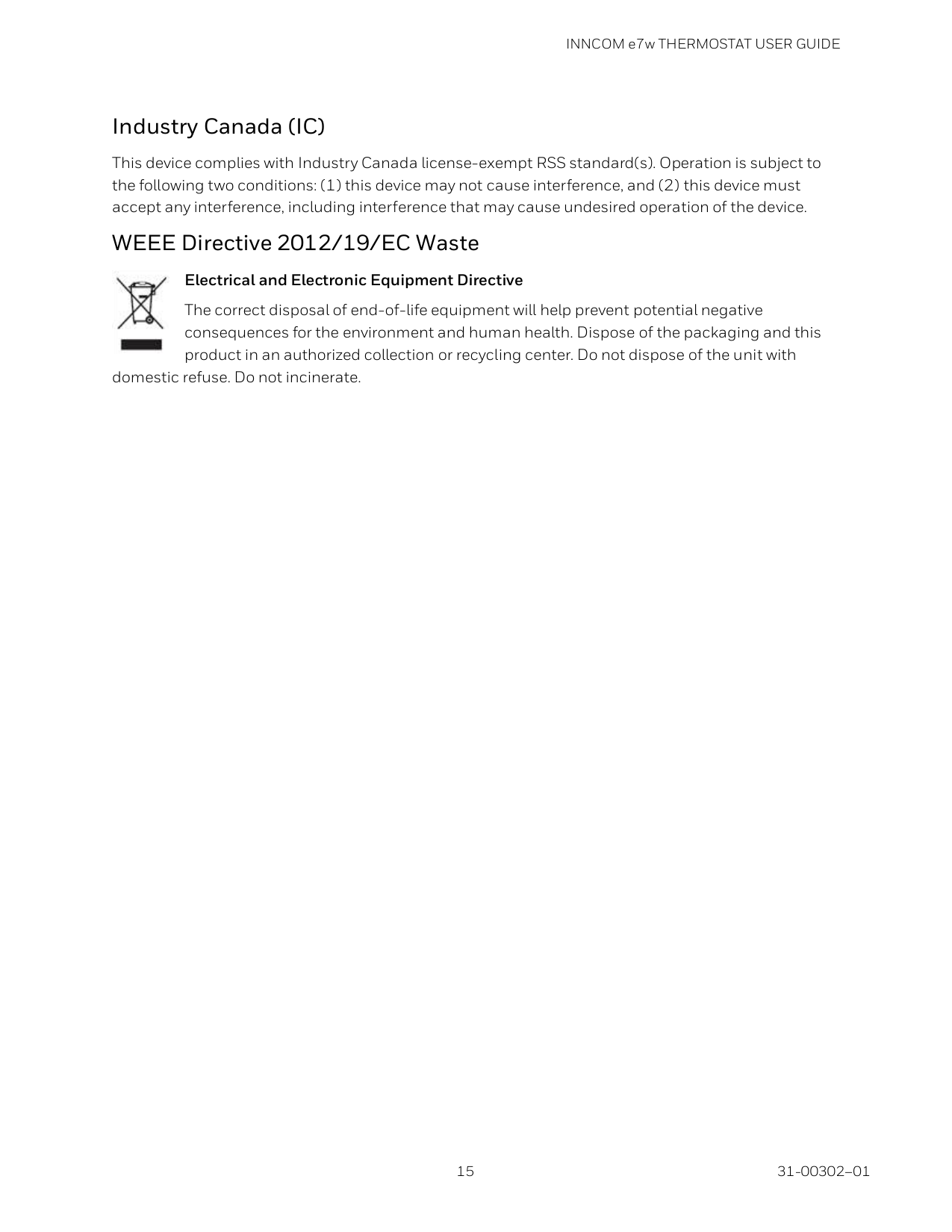
INNCOM e7w THERMOSTAT USER GUIDE
15 31-00302–01
Industry Canada (IC) This device complies with Industry Canada license-exempt RSS standard(s). Operation is subject to the following two conditions: (1) this device may not cause interference, and (2) this device must accept any interference, including interference that may cause undesired operation of the device. WEEE Directive 2012/19/EC Waste Electrical and Electronic Equipment Directive The correct disposal of end-of-life equipment will help prevent potential negative consequences for the environment and human health. Dispose of the packaging and this product in an authorized collection or recycling center. Do not dispose of the unit with domestic refuse. Do not incinerate.
INNCOM e7w THERMOSTAT USER GUIDE 31-00302–01 16
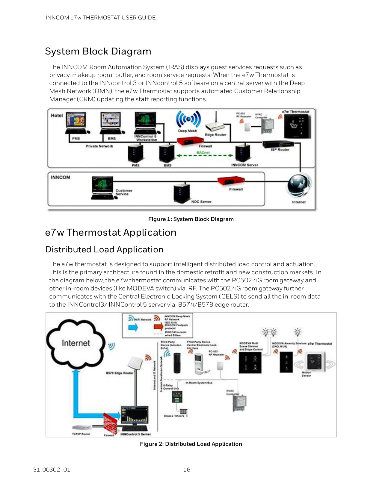
System Block Diagram The INNCOM Room Automation System (IRAS) displays guest services requests such as privacy, makeup room, butler, and room service requests. When the e7w Thermostat is connected to the INNcontrol 3 or INNcontrol 5 software on a central server with the Deep Mesh Network (DMN), the e7w Thermostat supports automated Customer Relationship Manager (CRM) updating the staff reporting functions.
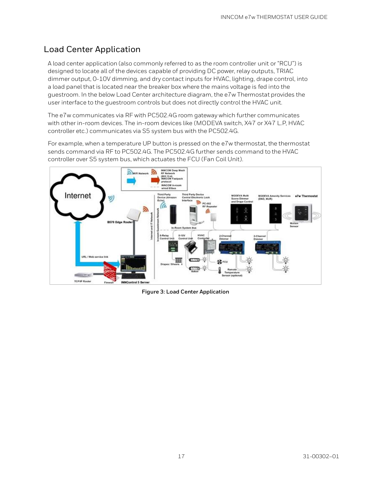
Figure 1: System Block Diagram e7w Thermostat Application Distributed Load Application The e7w thermostat is designed to support intelligent distributed load control and actuation. This is the primary architecture found in the domestic retrofit and new construction markets. In the diagram below, the e7w thermostat communicates with the PC502.4G room gateway and other in-room devices (like MODEVA switch) via. RF. The PC502.4G room gateway further communicates with the Central Electronic Locking System (CELS) to send all the in-room data to the INNControl3/ INNControl 5 server via. B574/B578 edge router.
Figure 2: Distributed Load Application
INNCOM e7w THERMOSTAT USER GUIDE
17 31-00302–01
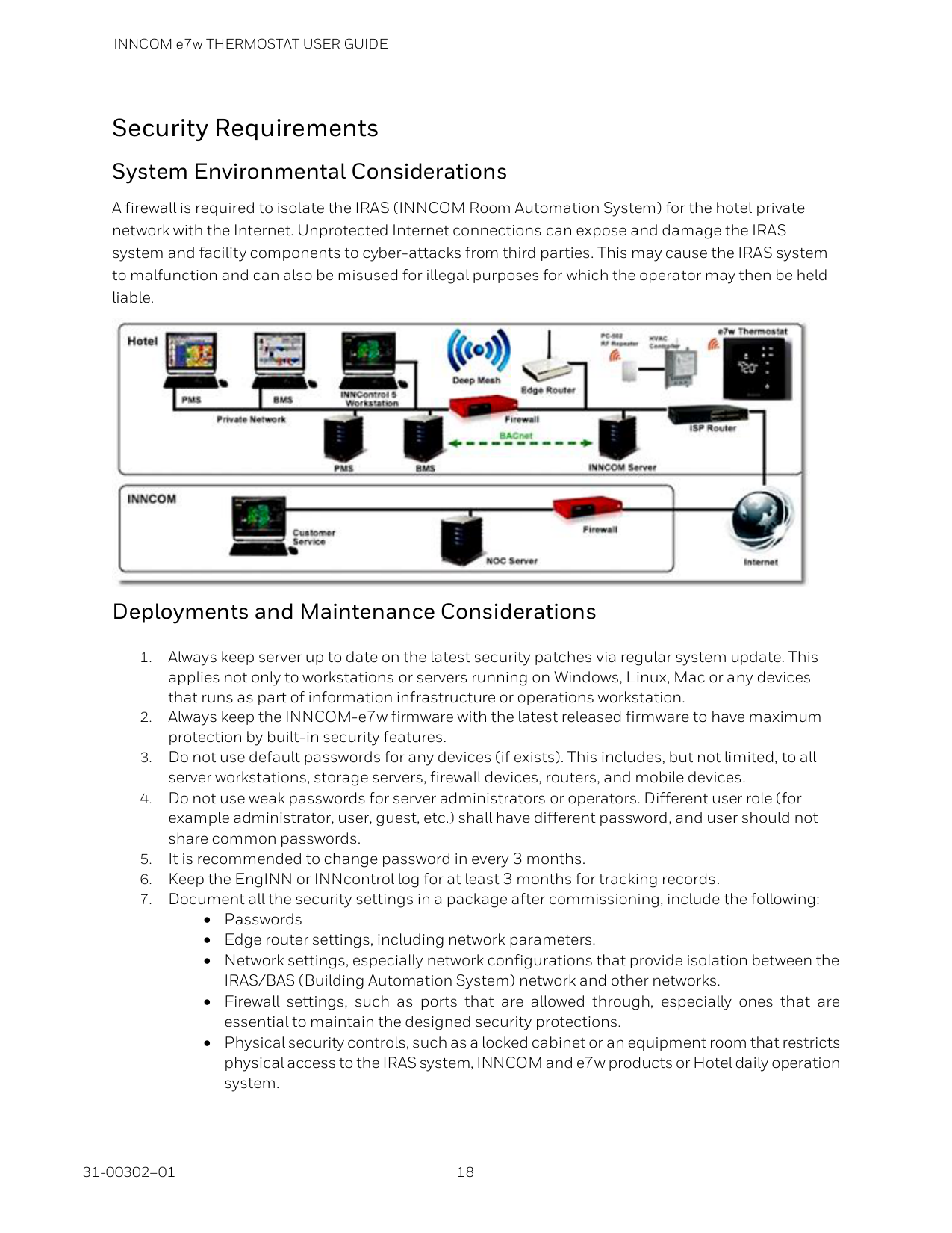
Load Center Application A load center application (also commonly referred to as the room controller unit or “RCU”) is designed to locate all of the devices capable of providing DC power, relay outputs, TRIAC dimmer output, 0-10V dimming, and dry contact inputs for HVAC, lighting, drape control, into a load panel that is located near the breaker box where the mains voltage is fed into the guestroom. In the below Load Center architecture diagram, the e7w Thermostat provides the user interface to the guestroom controls but does not directly control the HVAC unit. The e7w communicates via RF with PC502.4G room gateway which further communicates with other in-room devices. The in-room devices like (MODEVA switch, X47 or X47 L.P, HVAC controller etc.) communicates via S5 system bus with the PC502.4G. For example, when a temperature UP button is pressed on the e7w thermostat, the thermostat sends command via RF to PC502.4G. The PC502.4G further sends command to the HVAC controller over S5 system bus, which actuates the FCU (Fan Coil Unit).
Figure 3: Load Center Application
INNCOM e7w THERMOSTAT USER GUIDE 31-00302–01 18
Security Requirements System Environmental Considerations A firewall is required to isolate the IRAS (INNCOM Room Automation System) for the hotel private network with the Internet. Unprotected Internet connections can expose and damage the IRAS system and facility components to cyber-attacks from third parties. This may cause the IRAS system to malfunction and can also be misused for illegal purposes for which the operator may then be held liable.
Deployments and Maintenance Considerations

INNCOM e7w THERMOSTAT USER GUIDE
19 31-00302–01
Network Communication Notice
INNCOM e7w THERMOSTAT USER GUIDE 31-00302–01 20
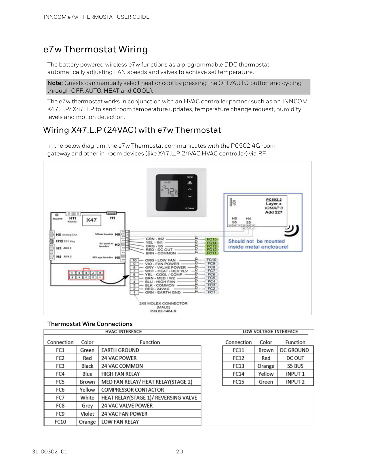
e7w Thermostat Wiring The battery powered wireless e7w functions as a programmable DDC thermostat, automatically adjusting FAN speeds and valves to achieve set temperature. Note: Guests can manually select heat or cool by pressing the OFF/AUTO button and cycling through OFF, AUTO, HEAT and COOL). The e7w thermostat works in conjunction with an HVAC controller partner such as an INNCOM X47.L.P/ X47H.P to send room temperature updates, temperature change request, humidity levels and motion detection. Wiring X47.L.P (24VAC) with e7w Thermostat In the below diagram, the e7w Thermostat communicates with the PC502.4G room gateway and other in-room devices (like X47.L.P 24VAC HVAC controller) via RF.
Thermostat Wire Connections
INNCOM e7w THERMOSTAT USER GUIDE
21 31-00302–01
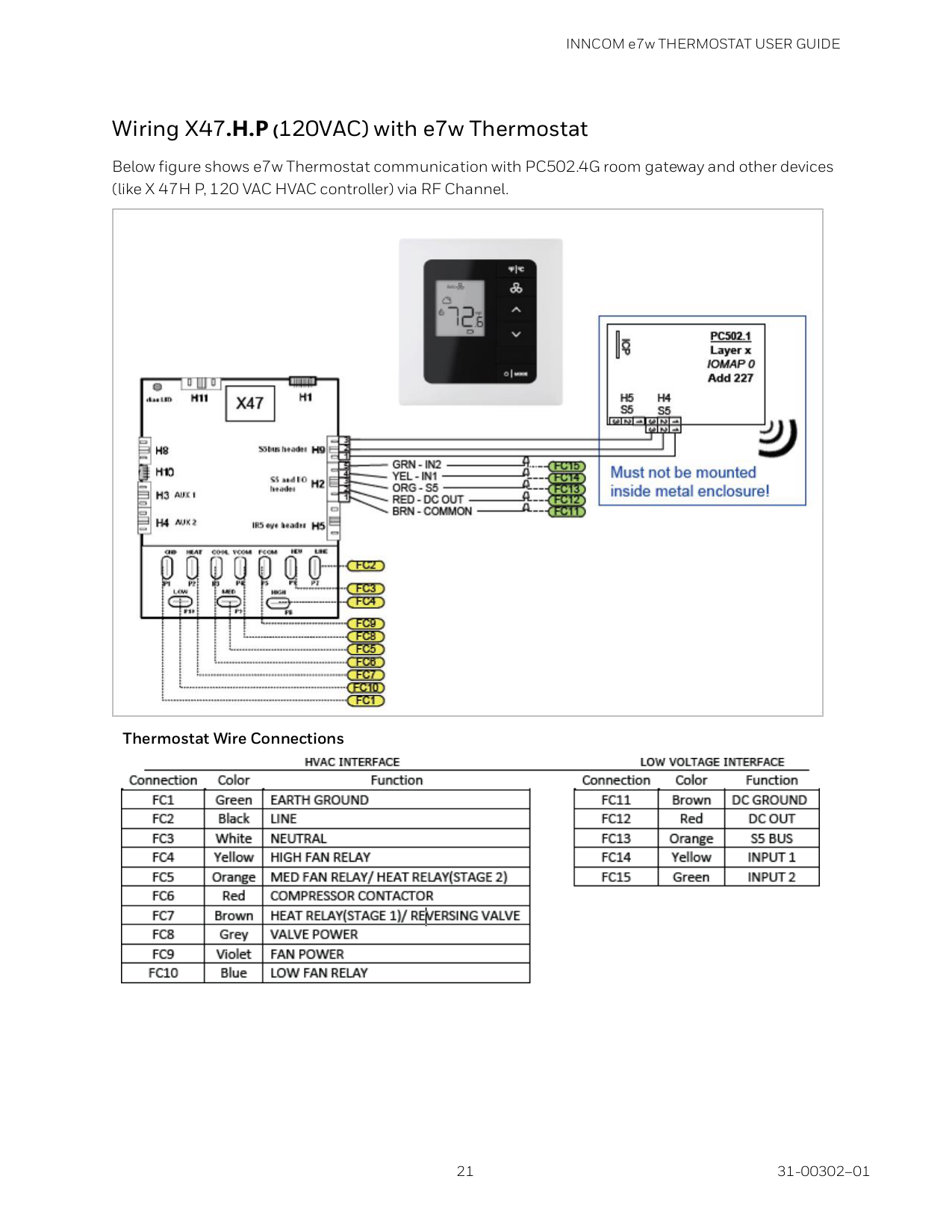
Wiring X47.H.P (120VAC) with e7w Thermostat Below figure shows e7w Thermostat communication with PC502.4G room gateway and other devices (like X 47H P, 120 VAC HVAC controller) via RF Channel.
Thermostat Wire Connections
INNCOM e7w THERMOSTAT USER GUIDE 31-00302–01 22
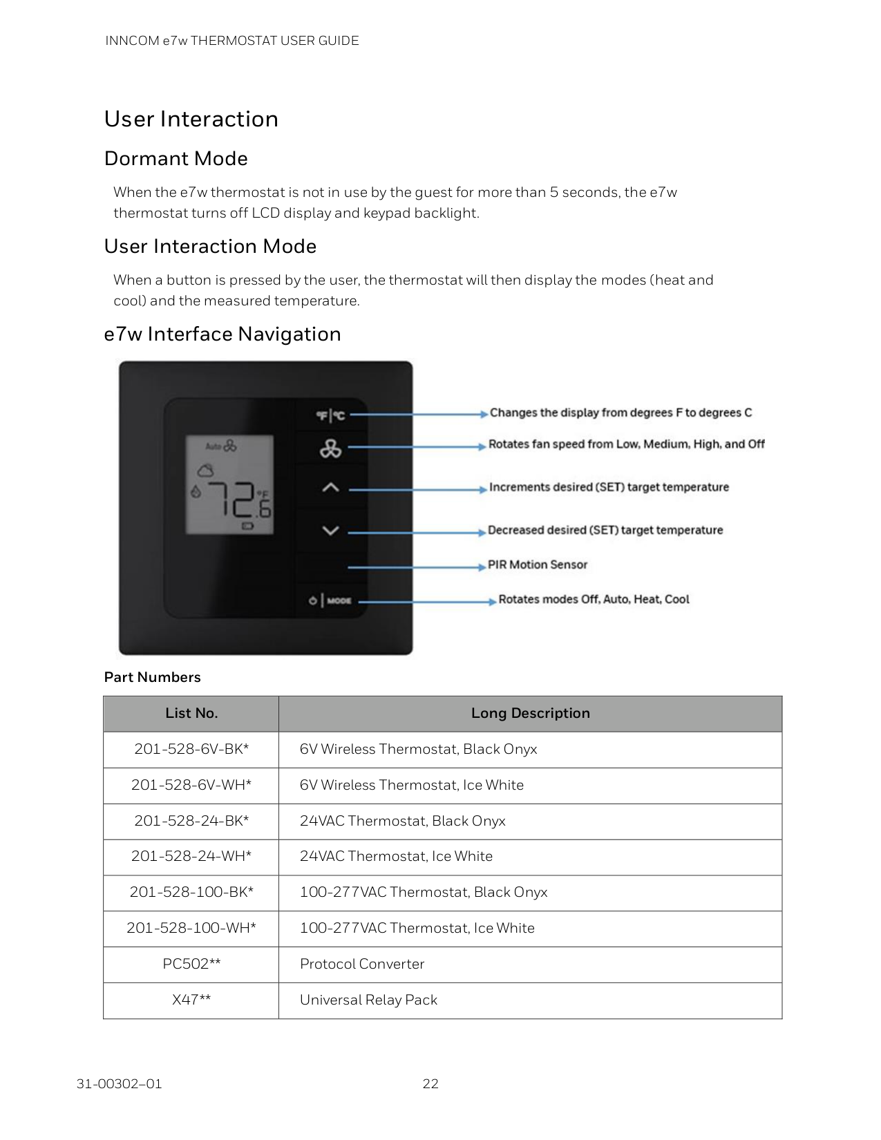
User Interaction Dormant Mode When the e7w thermostat is not in use by the guest for more than 5 seconds, the e7w thermostat turns off LCD display and keypad backlight. User Interaction Mode When a button is pressed by the user, the thermostat will then display the modes (heat and cool) and the measured temperature. e7w Interface Navigation
Part Numbers List No. Long Description
201-528-6V-Bk*
6V Wireless Thermostat, Black Onyx201-528-6V-Wh*
6V Wireless Thermostat, Ice White201-528-24-Bk*
24VAC Thermostat, Black Onyx201-528-24-Wh*
24VAC Thermostat, Ice White201-528-100-Bk*
100-277VAC Thermostat, Black Onyx201-528-100-Wh*
100-277VAC Thermostat, Ice WhitePc502**
Protocol ConverterX47**
Universal Relay Pack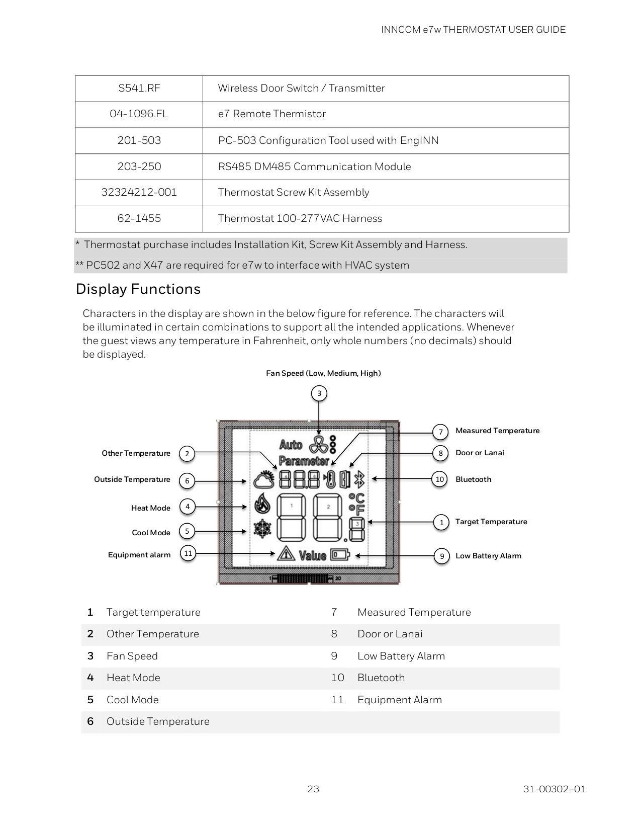
INNCOM e7w THERMOSTAT USER GUIDE
23 31-00302–01
S541.Rf
Wireless Door Switch / Transmitter04-1096.Fl
e7 Remote Thermistor 201-503 PC-503 Configuration Tool used with EngINN 203-250 RS485 DM485 Communication Module 32324212-001 Thermostat Screw Kit Assembly 62-1455 Thermostat 100-277VAC Harness1 Target temperature 7 Measured Temperature 2 Other Temperature 8 Door or Lanai 3 Fan Speed 9 Low Battery Alarm 4 Heat Mode 10 Bluetooth 5 Cool Mode 11 Equipment Alarm 6 Outside Temperature
11 11 5 4 6 9 1 10 10 8 7 3 Other Temperature Outside Temperature Cool Mode Heat Mode Equipment alarm Measured Temperature Door or Lanai Bluetooth Target Temperature Low Battery Alarm 2 Fan Speed (Low, Medium, High)
INNCOM e7w THERMOSTAT USER GUIDE 31-00302–01 24
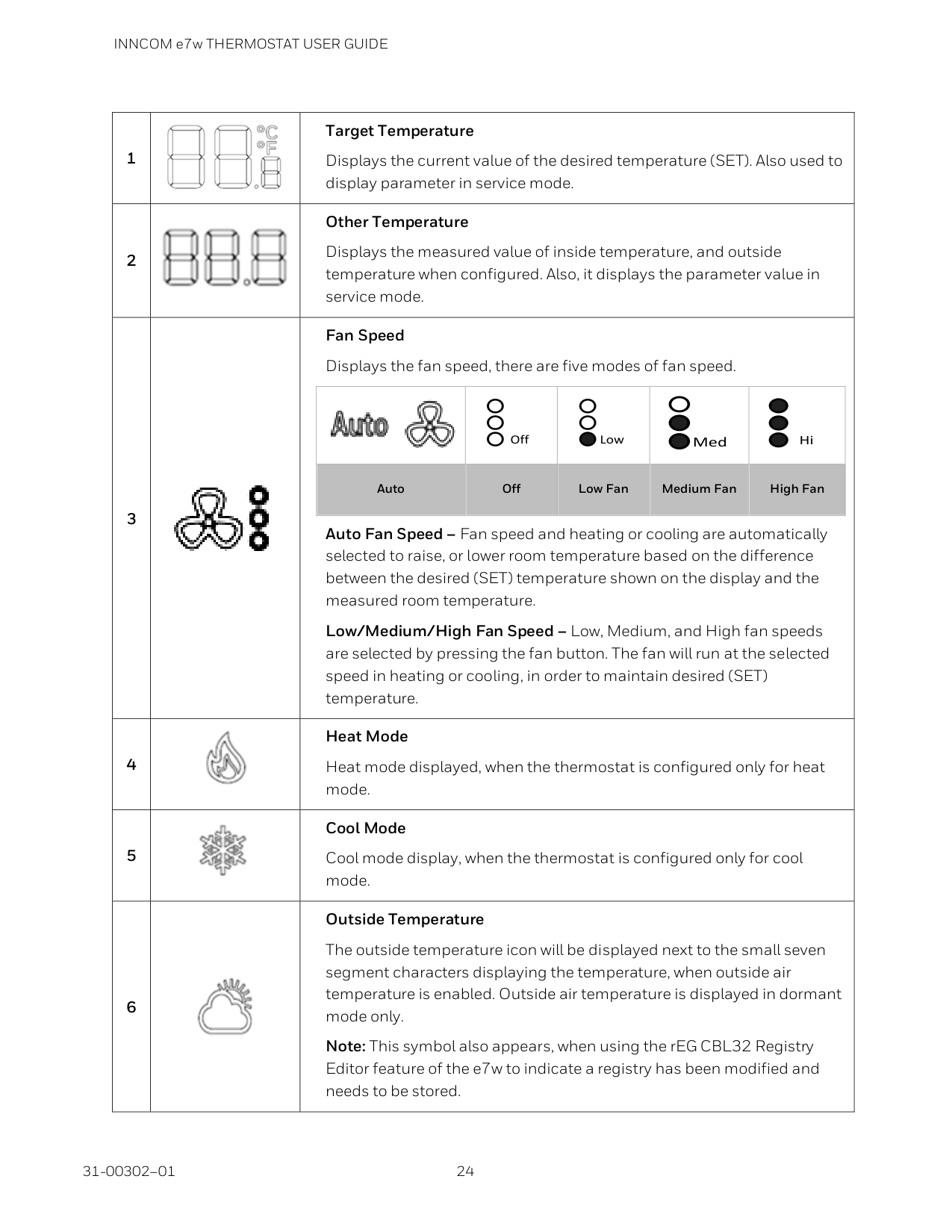
1
Target Temperature Displays the current value of the desired temperature (SET). Also used to display parameter in service mode. 2
Other Temperature Displays the measured value of inside temperature, and outside temperature when configured. Also, it displays the parameter value in service mode. 3
Fan Speed Displays the fan speed, there are five modes of fan speed.
Off Low Med Hi
Auto Off Low Fan Medium Fan High Fan Auto Fan Speed – Fan speed and heating or cooling are automatically selected to raise, or lower room temperature based on the difference between the desired (SET) temperature shown on the display and the measured room temperature. Low/Medium/High Fan Speed – Low, Medium, and High fan speeds are selected by pressing the fan button. The fan will run at the selected speed in heating or cooling, in order to maintain desired (SET) temperature. 4
Heat Mode Heat mode displayed, when the thermostat is configured only for heat mode. 5
Cool Mode Cool mode display, when the thermostat is configured only for cool mode. 6
Outside Temperature The outside temperature icon will be displayed next to the small seven segment characters displaying the temperature, when outside air temperature is enabled. Outside air temperature is displayed in dormant mode only. Note: This symbol also appears, when using the rEG CBL32 Registry Editor feature of the e7w to indicate a registry has been modified and needs to be stored.
INNCOM e7w THERMOSTAT USER GUIDE
25 31-00302–01
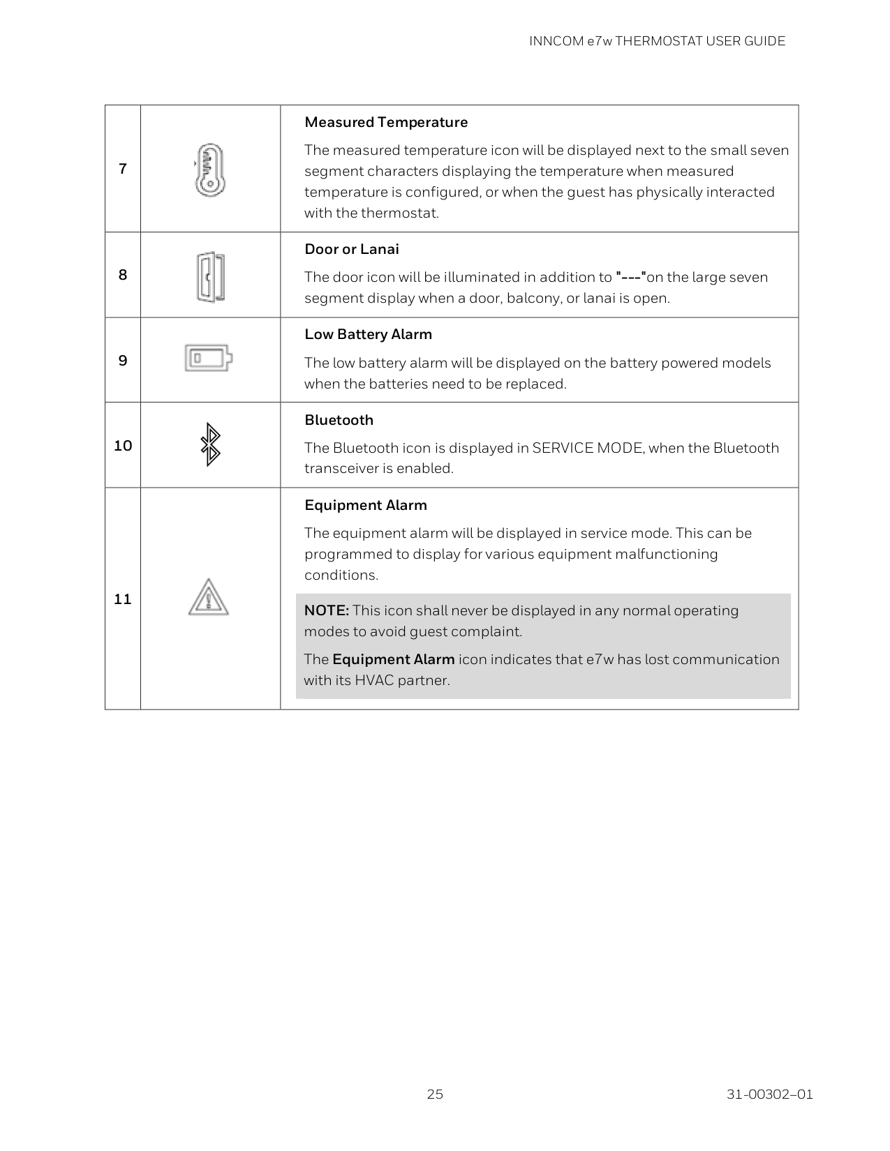
7
Measured Temperature The measured temperature icon will be displayed next to the small seven segment characters displaying the temperature when measured temperature is configured, or when the guest has physically interacted with the thermostat. 8
Door or Lanai The door icon will be illuminated in addition to "---"on the large seven segment display when a door, balcony, or lanai is open. 9
Low Battery Alarm The low battery alarm will be displayed on the battery powered models when the batteries need to be replaced. 10
Bluetooth The Bluetooth icon is displayed in SERVICE MODE, when the Bluetooth transceiver is enabled. 11
Equipment Alarm The equipment alarm will be displayed in service mode. This can be programmed to display for various equipment malfunctioning conditions. NOTE: This icon shall never be displayed in any normal operating modes to avoid guest complaint. The Equipment Alarm icon indicates that e7w has lost communication with its HVAC partner.
INNCOM e7w THERMOSTAT USER GUIDE 31-00302–01 26
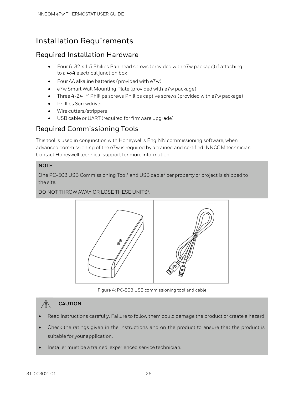
Installation Requirements Required Installation Hardware • Four 6-32 x 1.5 Philips Pan head screws (provided with e7w package) if attaching to a 4x4 electrical junction box • Four AA alkaline batteries (provided with e7w) • e7w Smart Wall Mounting Plate (provided with e7w package) • Three 4-24 1/2 Phillips screws Phillips captive screws (provided with e7w package) • Phillips Screwdriver • Wire cutters/strippers • USB cable or UART (required for firmware upgrade) Required Commissioning Tools This tool is used in conjunction with Honeywell's EngINN commissioning software, when advanced commissioning of the e7w is required by a trained and certified INNCOM technician. Contact Honeywell technical support for more information.
Note
One PC-503 USB Commissioning Tool* and USB cable* per property or project is shipped to the site.Do Not Throw Away Or Lose These Units*.
Figure 4: PC-503 USB commissioning tool and cable
Caution
• Read instructions carefully. Failure to follow them could damage the product or create a hazard. • Check the ratings given in the instructions and on the product to ensure that the product is suitable for your application. • Installer must be a trained, experienced service technician.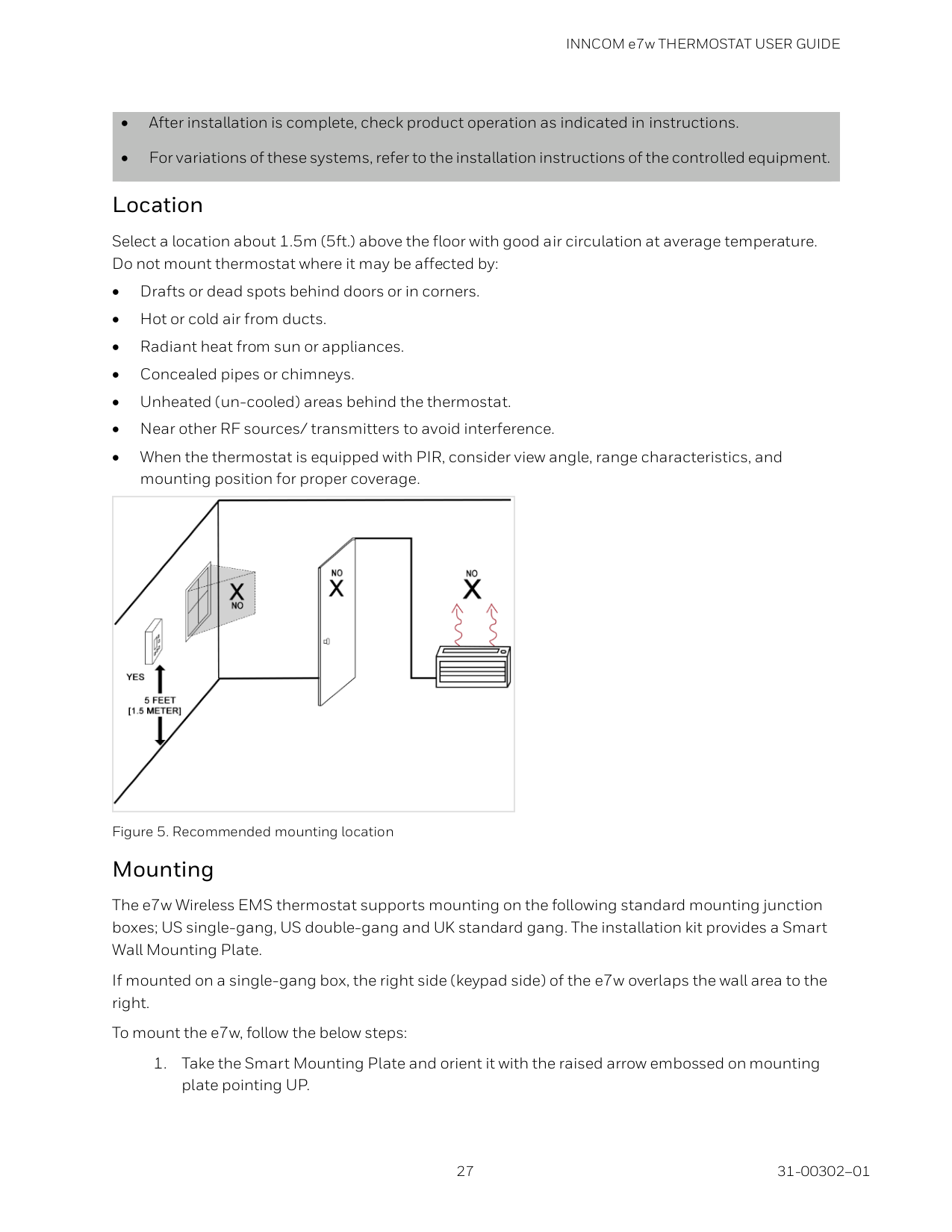
INNCOM e7w THERMOSTAT USER GUIDE
27 31-00302–01
• After installation is complete, check product operation as indicated in instructions. • For variations of these systems, refer to the installation instructions of the controlled equipment. Location Select a location about 1.5m (5ft.) above the floor with good air circulation at average temperature. Do not mount thermostat where it may be affected by: • Drafts or dead spots behind doors or in corners. • Hot or cold air from ducts. • Radiant heat from sun or appliances. • Concealed pipes or chimneys. • Unheated (un-cooled) areas behind the thermostat. • Near other RF sources/ transmitters to avoid interference. • When the thermostat is equipped with PIR, consider view angle, range characteristics, and mounting position for proper coverage.
Figure 5. Recommended mounting location Mounting The e7w Wireless EMS thermostat supports mounting on the following standard mounting junction boxes; US single-gang, US double-gang and UK standard gang. The installation kit provides a Smart Wall Mounting Plate. If mounted on a single-gang box, the right side (keypad side) of the e7w overlaps the wall area to the right. To mount the e7w, follow the below steps:
INNCOM e7w THERMOSTAT USER GUIDE 31-00302–01 28
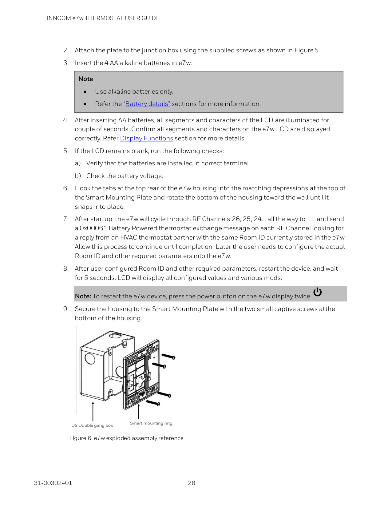
Figure 6. e7w exploded assembly reference
INNCOM e7w THERMOSTAT USER GUIDE
29 31-00302–01
Battery Details
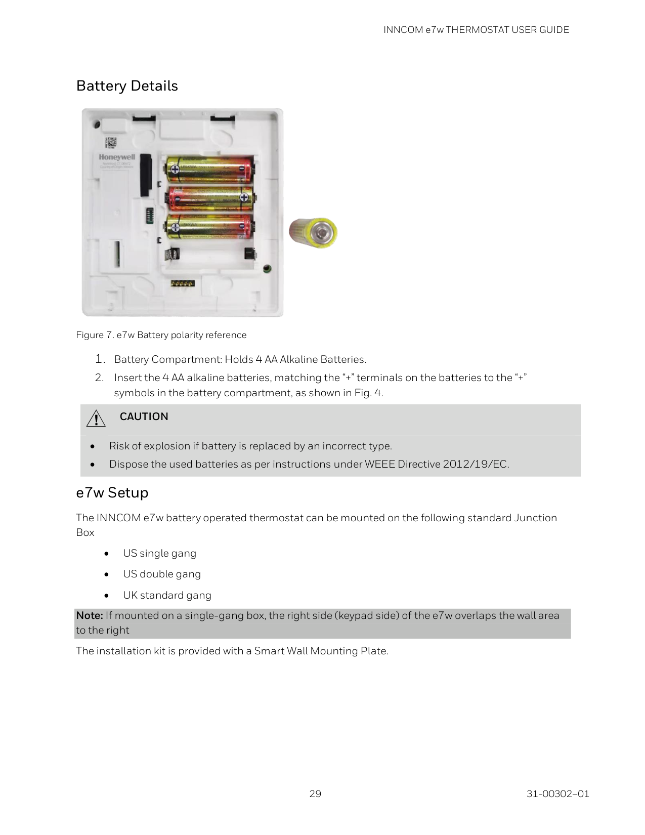
Figure 7. e7w Battery polarity reference
Caution
• Risk of explosion if battery is replaced by an incorrect type. • Dispose the used batteries as per instructions under WEEE Directive 2012/19/EC. e7w Setup The INNCOM e7w battery operated thermostat can be mounted on the following standard Junction Box • US single gang • US double gang • UK standard gang Note: If mounted on a single-gang box, the right side (keypad side) of the e7w overlaps the wall area to the right The installation kit is provided with a Smart Wall Mounting Plate.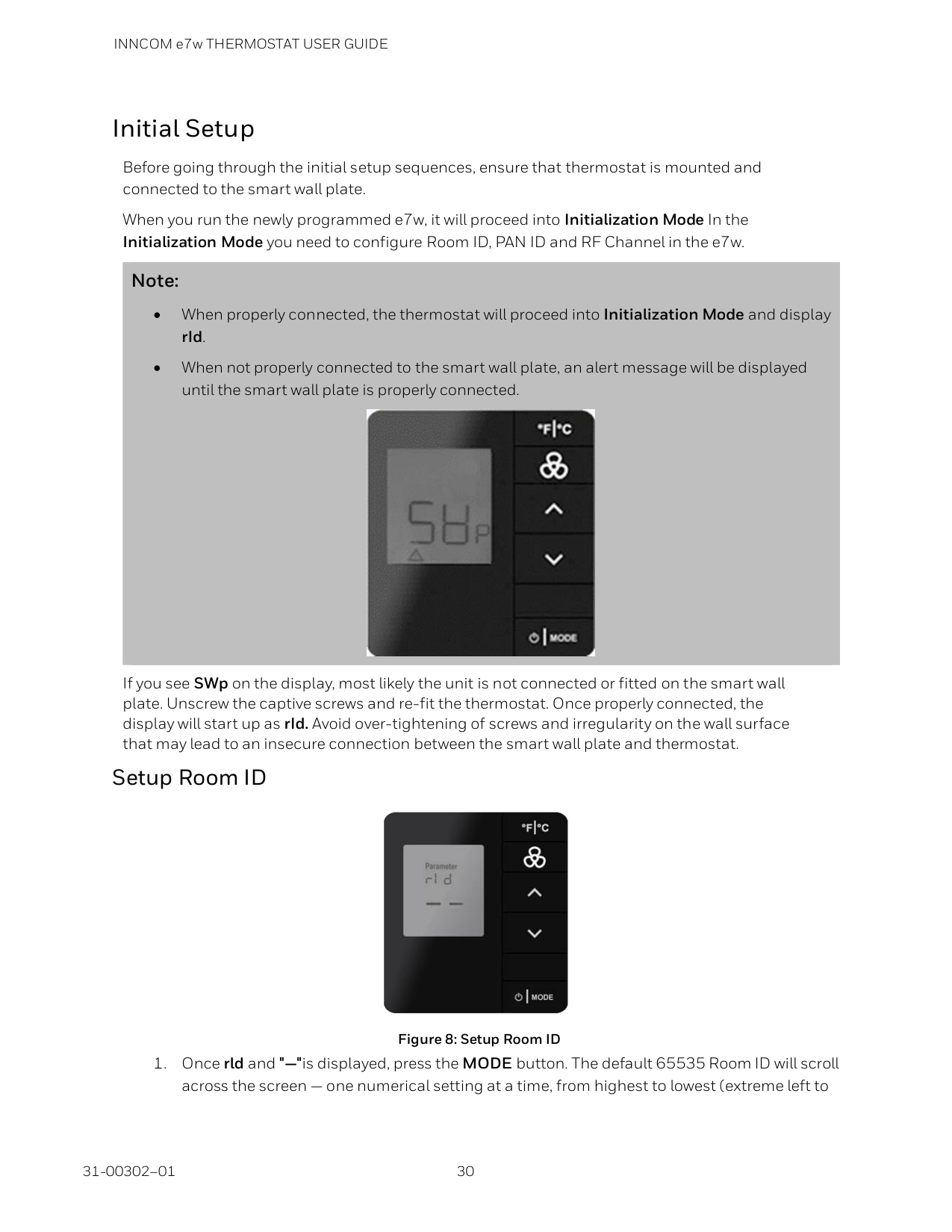
INNCOM e7w THERMOSTAT USER GUIDE 31-00302–01 30
Initial Setup Before going through the initial setup sequences, ensure that thermostat is mounted and connected to the smart wall plate. When you run the newly programmed e7w, it will proceed into Initialization Mode In the Initialization Mode you need to configure Room ID, PAN ID and RF Channel in the e7w. Note: • When properly connected, the thermostat will proceed into Initialization Mode and display rId. • When not properly connected to the smart wall plate, an alert message will be displayed until the smart wall plate is properly connected.
If you see SWp on the display, most likely the unit is not connected or fitted on the smart wall plate. Unscrew the captive screws and re-fit the thermostat. Once properly connected, the display will start up as rId. Avoid over-tightening of screws and irregularity on the wall surface that may lead to an insecure connection between the smart wall plate and thermostat. Setup Room ID
INNCOM e7w THERMOSTAT USER GUIDE
31 31-00302–01
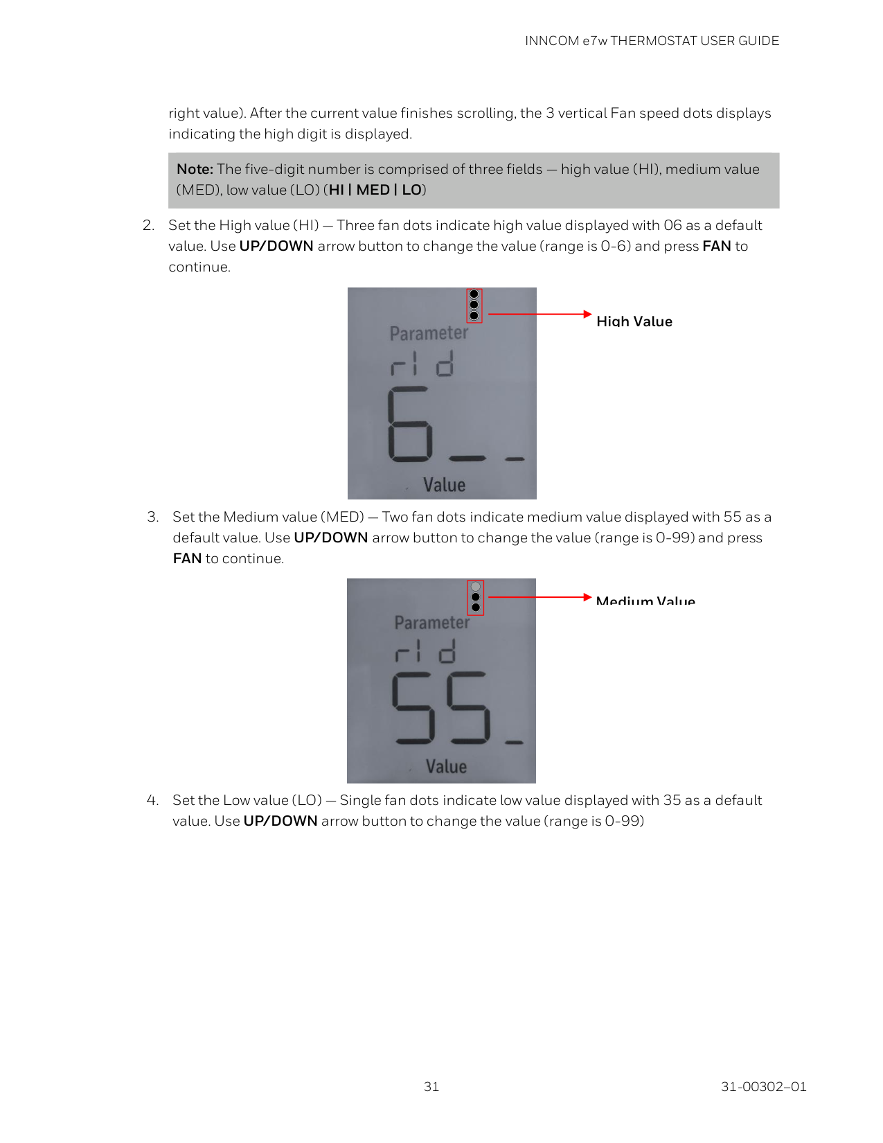
right value). After the current value finishes scrolling, the 3 vertical Fan speed dots displays indicating the high digit is displayed. Note: The five-digit number is comprised of three fields — high value (HI), medium value (MED), low value (LO) (HI | MED | LO)
INNCOM e7w THERMOSTAT USER GUIDE 31-00302–01 32
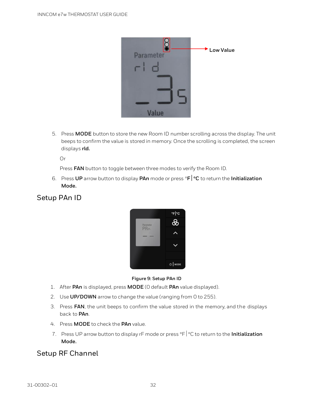
Figure 9: Setup PAn ID
INNCOM e7w THERMOSTAT USER GUIDE
33 31-00302–01
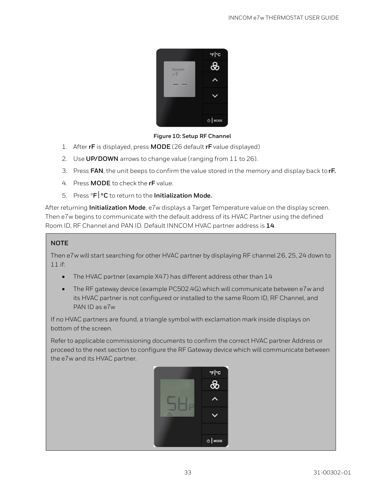
Figure 10: Setup RF Channel
Note
Then e7w will start searching for other HVAC partner by displaying RF channel 26, 25, 24 down to 11 if: • The HVAC partner (example X47) has different address other than 14 • The RF gateway device (example PC502.4G) which will communicate between e7w and its HVAC partner is not configured or installed to the same Room ID, RF Channel, and PAN ID as e7w If no HVAC partners are found, a triangle symbol with exclamation mark inside displays on bottom of the screen. Refer to applicable commissioning documents to confirm the correct HVAC partner Address or proceed to the next section to configure the RF Gateway device which will communicate between the e7w and its HVAC partner.
INNCOM e7w THERMOSTAT USER GUIDE 31-00302–01 34
Service Mode To enter Service Mode, follow the below steps:
INNCOM e7w THERMOSTAT USER GUIDE
35 31-00302–01
Activating LEM mode in the e7w HVAC partner using the e7w Inncom e7w thermostat/HVAC partner supports LEM (Limited Energy Management) mode, where the thermostat turns off most of the energy savings algorithms and expands the guest selectable upper and lower target temperature range. This feature can be enabled in a room that has a demanding guest that requires more flexible room temperature control than what is normally allowed for a room. LEM mode in the e7w HVAC partner can be enabled or disabled from the e7w using a 3 button sequence. Enabling LEM Mode Follow the below steps, to enable LEM mode in the HVAC partner from the e7w:
Note
LEM mode in the HVAC partner will automatically turn OFF after 72 hours. In thermostats/HVAC controllers that have been shipped recently (contact Inncom for details), LEM mode will automatically clear when the room is Checked-Out from the front desk (if the hotel is networked with a PMS system installed). Manual Disabling LEM Mode Follow the below steps, to manually disable LEM mode in the HVAC partner from the e7w:
INNCOM e7w THERMOSTAT USER GUIDE 31-00302–01 36
Binding Auxiliary Devices Once the e7w is installed and configured with its HVAC Partner Address, the next step is to use either the e7w or the EngINN software (with the PC503 USB commissioning tool) to commission the other devices in the room. NOTE: The e7w can be used as commissioning tool, refer applicable commissioning document for exact steps. Binding the RF to S5 Gateway Used by the e7w In order for the e7w to communicate with any in-room S5 Bus devices, the e7w must be bound to an RF device in the room that is connected to the S5 Bus. This RF device will typically be a PC502.4G. Follow the steps below to bind the PC502.4G using the e7w.

INNCOM e7w THERMOSTAT USER GUIDE
37 31-00302–01

INNCOM e7w THERMOSTAT USER GUIDE 31-00302–01 38
b ) The device in the room that is monitoring and reporting entry door position sends a 0x000281 Door Open message to the e7w. c ) The device in the room that is the Door Server sends a 0x0002981 Door Server Reports Door Open message to the e7w.

INNCOM e7w THERMOSTAT USER GUIDE
39 31-00302–01
Service Mode Functions Menu Item Description Value rId Use to configure the Room ID. 0 to 65535 PAn Use to configure the ZigBee pan used in radio communications. 0 to 255 rF Use to configure the channel used for IRAS communications. 11 to 26 Adr Use to “Teach” IRAS device the unique identification information, that binds to room or network. 0 to 255 Io Use to configure I/O Map on a remote device. 0 to 255 rEG Use to view or edit the CBL32 Registry values of the CBL32 HVAC thermostat or controller partner to the e7w such as a CBL32 X47. 1 to 255 PnG Use to signal to connected devices and registers response. The timeout duration of the ping is 1 minute. 0 to 255 rH Use to verify humidity 0 to 99 rSt Use to reset the thermostat- VAL 0 or remote device with specified address or VAL 0 to 255 WAn Use to verify WAN communication. Sends an event to the server. The server in turn will reply with a command that lets the room ID scroll over the display of the thermostat. 0 dor Use to verify Door sensor. The buzzer will sound as long as the door is open, and the LCD counts the number of times the door has gone from closed to open. 0 Plr Use to verify PIR sensor. When Passive Infrared Motion (PIR) sensor detects the guest motion, it plays buzzer sound and the LCD counts the number of times the application has increased the motion counter. The timeout duration is one minute. 0 Win Use to verify the monitored window/balcony/ position in the guestroom. The buzzer will sound as long as the window/balcony is open, and the LCD counts the number of times the window/balcony changed from closed to open. 0

INNCOM e7w THERMOSTAT USER GUIDE 31-00302–01 40
Menu Item Description Value bnd Use to configure Forward and Reverse binding. e7w supports binding and configuration for both RF devices (S541.RF Door, Window or Balcony switches) and Non-RF S5 bus connected devices (PC502.4G). 0 to 255 vEr Use to display the version of 16 firmware banks, such as main firmware version, bootloader version, IRAS, CBL, APP Map, etc. Displays the major and minor versions of each bank and the application personality. Contact an INNCOM Applications Engineer for a detailed understanding of this parameter. 0 Prr Use to verify the connectivity between remote PIR Motion sensor and an INNCOM room devices 0 bAu Use to display battery level range from 0-255 (255=full, 6.2V 4 AA batteries) for 1 minute 0 to 255 SEr Use to run menu parameters of the CBL32 partner device (e.g.
X47).
0 to 255P5C
Use to view or set the P5 Channel of e7w (default channel is 1) 0 to 7Pa
Set P5 partner address. This address considers as default address of the HVAC controller partner, which is configured with e7w. This partner address receives any message sent by e7w. 1 to 255 Pi5 Use to read and Process Image (PI) offset from the HVAC partner device. Process Image viewer is an advanced feature intended to be used by an INNCOM technician for advanced troubleshooting. 0 to 31E7W
Use to change the e7w local address. 13 is the default for E7W 1to 255 oAt Use to displays outside air temperature 0 PFt Use to adjust the sensitivity of the e7w built in PIR motion sensor. 1to 4 Ctr Contractor mode allows conditioning a space during the construction phase to a defined set temperature and locking out the key pad to prevent tampering. 0
INNCOM e7w THERMOSTAT USER GUIDE
41 31-00302–01
RID – Setting e7w Room ID (rld)
High Value

INNCOM e7w THERMOSTAT USER GUIDE 31-00302–01 42
Medium Value Low Value

INNCOM e7w THERMOSTAT USER GUIDE
43 31-00302–01
PAN – Setting e7w PAn ID (PAn)

INNCOM e7w THERMOSTAT USER GUIDE 31-00302–01 44

INNCOM e7w THERMOSTAT USER GUIDE
45 31-00302–01
a) After pressing FAN button, "bnd" will appear on the e7w display.
b) Press Bind button on target device, to make the target device send a Reverse Bind Request to e7w. c) Upon receiving the Reverse Bind Request, the e7w send a Bind offer to the target device. d) After the target device receives and accept the new address, the target device Reset and send message to e7w. e) After receiving the message e7w beep three times to confirm the binding. NOTE: For more details, refer applicable commissioning document. Forward Binding Forward binding is supported by devices such as an L208.RF, Evora, Modeva etc. To configure using forward binding, follow the below steps. a) Place the target device into a Bind Ready mode. This can be done by pressing any button on the target device two times quickly, then press and hold the button for 5-7 seconds. b) Press MODE button on e7w. The e7w send a Forward Bind Request. c) After receiving the Forward Bind Request, the target device flashes LED confirming that it receives the Forward Bind Request. • For binding RF devices, press bind button on the target device two times quickly, then press and hold bind button for 5-7 seconds to accept the bind request. • For binding Non-RF devices, press bind button once on the target device to accept the bind request. d) After accepting the new address, the target device will Reset and send a “sound buzzer” message to e7w. e) After receiving the message, e7w beep three times as an audible indication that the bind was successful.

INNCOM e7w THERMOSTAT USER GUIDE 31-00302–01 46
Or Press the FC button twice to exit SERVICE MODE NOTE: For more details, refer applicable commissioning document. IO – Teaching A Device I/O Map (Io) The Io parameter is used to bind the target device to the Room ID, PAN ID, and RF channel configured in the e7w, while at the same time activating an I/O Map in the target device. Follow the steps below to configure Io parameter: NOTE: Before user start configuring IO mode, you need configure Room ID, PAN ID and RF Channel in the e7w.

INNCOM e7w THERMOSTAT USER GUIDE
47 31-00302–01
b) Press Bind button on the target device to make the target send a Reverse Bind Request to the e7w. c) Upon receiving the Reverse Bind Request, the e7w send a Bind offer to the target device. d) After the target device receives and accepts the bind offer containing the new I/O Map, the target device will RESET and send a “sound buzzer” message to e7w. e) After receiving the message the e7w beep three times to confirm the binding. NOTE: For more details, refer applicable commissioning document. Forward Binding Forward binding is supported by devices such as an L208.RF, Evora, Modeva etc. To configure using forward binding, follow the below steps. a) Place the target device into a Bind Ready mode. This can be done by pressing Bind button on the target device two times quickly, then press and hold Bind button for 5-7 seconds b) Press MODE button on e7w, the e7w send a Forward Bind Request.

INNCOM e7w THERMOSTAT USER GUIDE 31-00302–01 48
c) After receiving the Forward Bind Request, the target device flashes LED confirming that it receives the Forward Bind Request. • For binding RF devices, press bind button on the target device two times quickly, then press and hold bind button for 5-7 seconds to accept the bind request. • For binding Non-RF devices, press bind button once on the target device to accept the bind request. d) After accepting the new I/O Map, the target device RESET and send message to e7w to make it sounds its audible buzzer. e) After receiving the message, e7w beep three times to confirm the binding.

INNCOM e7w THERMOSTAT USER GUIDE
49 31-00302–01
REG – CBL32 Registry Edit (rEG) Use the rEG mode to view or edit CBL32 Registry Group 9 Thermo/HVAC and Registry Group 7:X:Y Input/output in the HVAC Partner device (i.e. X47) to the e7w.

INNCOM e7w THERMOSTAT USER GUIDE 31-00302–01 50
If Group 9 Thermo/HVAC selected as the Gr. (Group) in step 4: Group 9 has no Index values, so the e7w will immediately send a 00018C09YY0000 Read Registry 09: YY Offset 0 command (YY = the Key value defined in step 6) to the address of the HVAC partner to verify the selected Registry 09: YY exists. ➢ If the selected Registry 09: YY exists in the HVAC partner, the e7w will beep and "Parameter" and 0 will be displayed. a) Use the UP/DOWN arrow buttons to select the desired 09: YY parameter offset. b) Press the MODE button to read and display the value if the selected offset. The e7w will send a 00018C09YY0000 Read Registry 09: YY Offset value to the HVAC partner. If a reply is received, the display will show "Value" and the value of the selected offset in decimal, and the e7w will beep. In the below example, Parameter 8 of the selected 9: YY registry has a value of 10.
➢ If the defined Registry 09: YY does NOT exist in the HVAC partner, nUL will be briefly displayed, then the e7w will return to displaying the selected Key value.
Value Use UP button to set parameter value to 8 , then press MODE button to view the value

INNCOM e7w THERMOSTAT USER GUIDE
51 31-00302–01
If Group 7 Input/Output selected as the Gr. (Group) in step 4: Group 7 registry's have an Index value that must be defined before defining the desired Offset, so after pressing the MODE button, (I dX or Index) and 0 will be displayed. a) Use the UP/ DOWN Arrow buttons to define the desired Index#. “1” in this example.
b) Press the MODE button. The e7w will send a 00018C07XXYY00 Read Registry 07: YY: XX Offset 0 (YY = the Key value defined in step 6, XX = Index value) command to the address of the HVAC partner to verify the selected Registry 07: YY: XX exists. ➢ If the selected Registry 07: YY: XX exists in the HVAC partner, the e7w will beep and "Parameter" and 0 will be displayed.
➢ If the defined Registry 07: YY: XX Index does NOT exist in the HVAC partner, nUL will be briefly displayed, then the e7w will return to displaying the selected Index value.

INNCOM e7w THERMOSTAT USER GUIDE 31-00302–01 52
b) When the desired level is reached, use the Up / Down arrow buttons to select the desired Group, Key, or Index value, then press the MODE button to view the value of the selected Group, Key, or Index value.
Value

INNCOM e7w THERMOSTAT USER GUIDE
53 31-00302–01
The following is a complete example of reading and changing a Group 9 Registry. Read Registry 9:1 Occupancy, Offset 8 Min_GuestOccupancyTimeout of the HVAC partner to the e7w. Change from the current value of 10 minutes to 15 minutes.
Press FAN button to store the changes Use Up/Down button to set value to 8 , then press MODE Value changed to 15 Current Value is 10. Use Up arrow button to change value to 15 Press FAN button to store the new value. Cloud/Sun symbol blinks to indicate registry value has been changed
Value Value Value Press F/C Button 4 times to exit out of rEG menus until Str (Store) appears on display
Use Up/Down button to select Gr value ,then press
Mode
Use Up/Down button to select Key value ,then pressMode
Parameter and value 0 be displayed. This is Registry 9:1 Offset 0 Press MODE
INNCOM e7w THERMOSTAT USER GUIDE 31-00302–01 54
The following is a complete example of reading and changing a Group 7 Registry. Read Registry 7:3:1 Light Output, Offset 20 Minlevel of an X45RA Address 30. Lower the current value of 40 to 20. In order to read the X45RA, which is not the HVAC partner to the e7w, you will need to change the current e7w Partner Address (PA) of 14 to 30, make the change to the X45RA, then change the e7w back to the original address of the e7w HVAC partner (14).
Press MODE Enter Service Mode and select PA parameter. Change value to 30 , press FAN to store change. e7w will beep and return to display PA Value
Value Select rE6 parameter and press MODE Change Group value to 7 and press MODE Change Key value to 3 and press MODE Change Index value to 1 and press MODE
Parameter and 0 will appear Change Parameter value to 20 and press MODE Current value of 40 is displayed. Change value to 20 and press FAN to store Value Value Cloud/Sun icon will blink indicating Registry value was changed. Press F/C button return to displaying Parameter value Press F/C button to exit back to Index (Idx) , Key and Group (Gr.) menus Value

INNCOM e7w THERMOSTAT USER GUIDE
55 31-00302–01
Enter Service Mode and select PA parameter. Change value to 14 , press FAN to store change. e7w will beep and return to display PA
Value Value
Press F/C button to exit back to reG (rE6) and press F/C again to get Str (Store) on the display. Press FAN button to store the change. The e7w will RESET and exit Service Parameter Mode

INNCOM e7w THERMOSTAT USER GUIDE 31-00302–01 56
PNG – Verifying Device Communication (PnG) Use the PnG (Ping) parameter to Ping a device with the defined address. This allows you to test, if the device is communicating directly with the e7w via RF, or if the device is communicating through S5 bus to an installed RF device. Ping all the installed devices from the e7w, while commissioning a room.

INNCOM e7w THERMOSTAT USER GUIDE
57 31-00302–01

INNCOM e7w THERMOSTAT USER GUIDE 31-00302–01 58
Press the FC button twice to exit SERVICE MODE RST – Resetting e7w (rSt) rSt parameter is used to reset the e7w, reboot the e7w back to Factory default settings or Reset a remote device.

INNCOM e7w THERMOSTAT USER GUIDE
59 31-00302–01
Note
There are two conditions to be satisfied for door test: • There is device in the room that is monitoring and reporting door position via a 0x000281 Entry Door Open message such as an S541. RF.
INNCOM e7w THERMOSTAT USER GUIDE 31-00302–01 60
• A device in the room that has its “P5 Door Server” enabled that reports a 0x0002981 “Door Server Reports Door is Open” when it sees the 0x000281 Entry Door Open message. This device will typically be the room HVAC controller (X47 or similar). The e7w watches for the 0x0002981 “Door Server Reports Door is Open” message for its door test.
Open the room entry door. The following sequence should happen The device used for monitoring and reporting entry door position sends a 0x000281 Door open message to the e7w. a ) The device used for reporting entry door position sends a 0x000281 Door open message into the room b ) The door server in the room sends 0x0002981 Door Server Reports Door Open message into the room. c ) Upon seeing the 0x0002981 Door Server Reports Door Open, the e7w will sound its buzzer sound and increment the displayed door open count.

INNCOM e7w THERMOSTAT USER GUIDE
61 31-00302–01

INNCOM e7w THERMOSTAT USER GUIDE 31-00302–01 62
Note
To perform window test, Following two conditions must be satisfied for window test: • A device in the room that is monitoring and reporting window position via a 0x0002A1 Window Open message • A device in the room that has its “P5 Window Server” enabled that reports a 0x0002B01 “Window Server Reports window is Open” for the e7w window test to work. The e7w watches for the0x0002B01 “Window Server Reports Window is Open” message for its window test.
INNCOM e7w THERMOSTAT USER GUIDE
63 31-00302–01

INNCOM e7w THERMOSTAT USER GUIDE 31-00302–01 64

INNCOM e7w THERMOSTAT USER GUIDE
65 31-00302–01

INNCOM e7w THERMOSTAT USER GUIDE 31-00302–01 66
PRR – Remote Motion Sensor (Prr) Use Prr mode to test the functionality of a PIR Motion sensor connected to an INNCOM room device, such as an X05B. For this test, the e7w looks for 0x000351 PIR Active and 0x000350 PIR In-Active messages being sent from the INNCOM in-room device with externally connected motion sensor.

INNCOM e7w THERMOSTAT USER GUIDE
67 31-00302–01
BAU – e7w Battery Level (bAu) Use bAu mode to view the battery level of the 4 AA batteries installed in the e7w. The value is reported as a 0-255 value, which is scaled to the 0-6.4 VDC of 4 batteries, each with 1.6-volt AA battery.
Note
A battery level of 4 volts or less will cause the e7w to display a low battery symbol on its display indicating that the 4 AA batteries need replacement. This condition will also result in a low battery alarm in the INNcontrol software. Refer below image
INNCOM e7w THERMOSTAT USER GUIDE 31-00302–01 68
SER – Service Parameter (Ser) Ser mode is used to execute “Run” menu parameters of the CBL32 partner device, such as a
X47.

INNCOM e7w THERMOSTAT USER GUIDE
69 31-00302–01
Below is a trace capture of the e7w (13) sending the command to the HVAC Partner (14) to execute Run Menu 10 with value 5:
Table 2: Run Parameter Value
Value Value
Change the desired Run Parameter value to 10 using the Up/Down buttons. Press MODE Change value to 5 using Up Arrow Press FAN button to execute

INNCOM e7w THERMOSTAT USER GUIDE 31-00302–01 70
P5C – P5 Channel Parameter (P5C) Use P5c mode to view or set the P5 Channel of e7w. It is by default set as 1. All INNCOM devices have a P5 Channel setting that can be set from 1 to 7. This setting can be used to segregate devices so that only certain devices can communicate with other certain devices. To communicate with each other, the devices must be set to the same P5 Channel.

INNCOM e7w THERMOSTAT USER GUIDE
71 31-00302–01

INNCOM e7w THERMOSTAT USER GUIDE 31-00302–01 72

INNCOM e7w THERMOSTAT USER GUIDE
73 31-00302–01
E7W – e7w Address Parameter (E7W) The local address of e7w is by default 13 If required to change the e7w local address, use E7W parameter. You would need to change the e7w local address if it was required to have more than one e7w installed in the same room. Each e7w must have a unique local address.
E7
A
E7
A
Value13
INNCOM e7w THERMOSTAT USER GUIDE 31-00302–01 74

INNCOM e7w THERMOSTAT USER GUIDE
75 31-00302–01
PFt – e7w PIR Motion Sensor Filter (PFt) Use the PFt parameter to adjust the sensitivity of the e7w built in PIR motion sensor.

INNCOM e7w THERMOSTAT USER GUIDE 31-00302–01 76

INNCOM e7w THERMOSTAT USER GUIDE
77 31-00302–01
Press any key to change set temperature, fan speed or mode and you will see that the ability to change these values are locked out. To exit CONTRACTOR MODE

INNCOM e7w THERMOSTAT USER GUIDE 31-00302–01 78
Binding and Testing RF Locks Using e7w Saflok RF Locks

INNCOM e7w THERMOSTAT USER GUIDE
79 31-00302–01
Timelox RF Locks

INNCOM e7w THERMOSTAT USER GUIDE 31-00302–01 80
Salto RF Locks

INNCOM e7w THERMOSTAT USER GUIDE
81 31-00302–01
Firmware Upgrade NOTE: While updating the firmware, make sure the device and the PC is connected with the USB or UART cable. Sometimes, the operator not able to decide, if the device is in firmware state or in the security bootloader state. Therefore, the device allowed to be in both state when updating the firmware. Follow the steps below to upgrade e7w firmware:

INNCOM e7w THERMOSTAT USER GUIDE 31-00302–01 82
This action completes upgrade. After all of the selected firmware is updated. EngINN tool sends End OTW command to the e7w to indicate, that the OTW process is finished. After receiving the End OTW command, the e7w reply an acknowledgement to EngINN and restart. After the EngINN receives the acknowledgement, it displays firmware update success.

INNCOM e7w THERMOSTAT USER GUIDE
83 31-00302–01
The material in this document is for information purposes only. The content and the product described are subject to change without notice. Honeywell makes no representations or warranties with respect to this document. In no event shall Honeywell be liable for technical or editorial omissions or mistakes in this document, nor shall it be liable for any damages, direct or incidental, arising out of or related to the use of this document. No part of this document may be reproduced in any form or by any means without prior written permission from Honeywell.