
Miller ArcReach Suitcase 12 Welder
Ask AI
— answers from the official manualAnswers from the official manual.
Common questions
Common Questions
10 totalWhat routine maintenance is recommended for the ArcReach Suitcase 12?
Remove the drive rolls and clean the grooves using a wire brush as part of routine maintenance. Additionally, the feeder has a shielding gas filter that requires special attention when cleaning (see Section 7-3 for proper cleaning instructions). (Page 17, 31)
What are the wire diameter ranges supported by the Miller ArcReach Suitcase 12?
The ArcReach Suitcase 12 supports flux cored wire with a diameter range of .030 - 3/32 inches (0.8 to 2.4 mm). The wire feed speed ranges from 25 - 400 ipm (0.64 - 10.2 mpm) depending on arc voltage. (Page 13)
How do I install the drive rolls on the Arcreach Suitcase 12?
First, turn the drive securing roll nut one click until the lobes line up with the lobes of the drive roll carrier. Then slide the drive roll onto the drive roll carrier and turn the nut one click. Repeat this procedure for the top drive roll. (Page 17)
What is the proper way to connect the welding gun to the feeder?
Loosen the gun securing knob and insert the gun power pin into the gun block, positioning it as close as possible to the drive rolls without touching them. Align the gun power pin groove with the gun locking tab and tighten the gun securing knob. Then connect the gun trigger plug to the gun trigger receptacle. (Page 18)
How do I thread welding wire into the ArcReach Suitcase 12?
Lay the gun cable out straight and open the pressure assembly. Hold the wire tightly and cut off the end. Guide the wire between alignment pins, into drive roll grooves, and into the gun liner. Close the pressure assembly and tighten the pressure adjustment knob enough to feed wire, then press the jog switch until wire comes out of the gun. (Page 21)
What is the maximum shielding gas pressure for the ArcReach Suitcase 12?
The shielding gas pressure must not exceed 100 psi (689 kPa). This pressure limit applies when connecting the shielding gas cylinder to the feeder. (Page 15)
Full Manual
41 pages
Owner’S Manual
Om-288742A
2020-10 Processes MIG (GMAW) Welding Flux Cored (FCAW) Welding Description Wire Feeder For product information, Owner’s Manual translations, and more, visit www.MillerWelds.com ArcReach ® SuitCase ® 12 Heavy Duty
Miller is the first welding equipment manufacturer in the U.S.A. to be registered to the
Iso
9001 Quality System Standard. Working as hard as you do − every power source from Miller is backed by the most hassle-free warranty in the business. Mil_Thank 2019-01 From Miller to You Thank you and congratulations on choosing Miller. Now you can get the job done and get it done right. We know you don’t have time to do it any other way. That’s why when Niels Miller first started building arc welders in 1929, he made sure his products offered long-lasting value and superior quality. Like you, his customers couldn’t afford anything less. Miller products had to be more than the best they could be. They had to be the best you could buy. Today, the people that build and sell Miller products continue the tradition. They’re just as committed to providing equipment and service that meets the high standards of quality and value established in 1929. This Owner’s Manual is designed to help you get the most out of your Miller products. Please take time to read the Safety Precautions. They will help you protect yourself against potential hazards on the worksite. We’ve made installation and operation quick and easy. With Miller, you can count on years of reliable service with proper maintenance. And if for some reason the unit needs repair, there’s a Troubleshooting section that will help you figure out what the problem is, and our extensive service network is there to help fix the problem. Warranty and maintenance information for your particular model are also provided. Miller Electric manufactures a full line of welders and welding-related equipment. For information on other quality Miller products, contact your local Miller distributor to receive the latest full line catalog or individual specification sheets. To locate your nearest distributor or service agency call 1-800-4-A-Miller, or visit us at www.MillerWelds.com on the web.
Table Of Contents
SECTION 1 – SAFETY PRECAUTIONS – READ BEFORE USING. . . . . . . . . . . . . . . . . . . . . . . . . . . . . . . . . . . . . . . . . . . . . . . . . . . . . . . . . . . . . . . . . . 1 1-1 Symbol Usage . . . . . . . . . . . . . . . . . . . . . . . . . . . . . . . . . . . . . . . . . . . . . . . . . . . . . . . . . . . . . . . . . . . . . . . . . . . . . . . . . . . . . . . . . . . . . . . . . . . . . . 1 1-2 Arc Welding Hazards . . . . . . . . . . . . . . . . . . . . . . . . . . . . . . . . . . . . . . . . . . . . . . . . . . . . . . . . . . . . . . . . . . . . . . . . . . . . . . . . . . . . . . . . . . . . . . . . 1 1-3 Additional Hazards For Installation, Operation, And Maintenance . . . . . . . . . . . . . . . . . . . . . . . . . . . . . . . . . . . . . . . . . . . . . . . . . . . . . . . . . . 3 1-4 California Proposition 65 Warnings . . . . . . . . . . . . . . . . . . . . . . . . . . . . . . . . . . . . . . . . . . . . . . . . . . . . . . . . . . . . . . . . . . . . . . . . . . . . . . . . . . . . 4 1-5 Principal Safety Standards. . . . . . . . . . . . . . . . . . . . . . . . . . . . . . . . . . . . . . . . . . . . . . . . . . . . . . . . . . . . . . . . . . . . . . . . . . . . . . . . . . . . . . . . . . . . 4 1-6 EMF Information . . . . . . . . . . . . . . . . . . . . . . . . . . . . . . . . . . . . . . . . . . . . . . . . . . . . . . . . . . . . . . . . . . . . . . . . . . . . . . . . . . . . . . . . . . . . . . . . . . . . 4 SECTION 2 – CONSIGNES DE SÉCURITÉ - LIRE AVANT UTILISATION. . . . . . . . . . . . . . . . . . . . . . . . . . . . . . . . . . . . . . . . . . . . . . . . . . . . . . . . . . . . 5 2-1 Symboles utilisés. . . . . . . . . . . . . . . . . . . . . . . . . . . . . . . . . . . . . . . . . . . . . . . . . . . . . . . . . . . . . . . . . . . . . . . . . . . . . . . . . . . . . . . . . . . . . . . . . . . . 5 2-2 Dangers relatifs au soudage à l’arc . . . . . . . . . . . . . . . . . . . . . . . . . . . . . . . . . . . . . . . . . . . . . . . . . . . . . . . . . . . . . . . . . . . . . . . . . . . . . . . . . . . . 5 2-3 Symboles de dangers supplémentaires en relation avec l’installation, le fonctionnement et la maintenance . . . . . . . . . . . . . . . . . . . . . . 7 2-4 Proposition californienne 65 Avertissements . . . . . . . . . . . . . . . . . . . . . . . . . . . . . . . . . . . . . . . . . . . . . . . . . . . . . . . . . . . . . . . . . . . . . . . . . . . . 9 2-5 Principales normes de sécurité . . . . . . . . . . . . . . . . . . . . . . . . . . . . . . . . . . . . . . . . . . . . . . . . . . . . . . . . . . . . . . . . . . . . . . . . . . . . . . . . . . . . . . . . 9 2-6 Informations relatives aux CEM . . . . . . . . . . . . . . . . . . . . . . . . . . . . . . . . . . . . . . . . . . . . . . . . . . . . . . . . . . . . . . . . . . . . . . . . . . . . . . . . . . . . . . . 9 SECTION 3 – DEFINITIONS . . . . . . . . . . . . . . . . . . . . . . . . . . . . . . . . . . . . . . . . . . . . . . . . . . . . . . . . . . . . . . . . . . . . . . . . . . . . . . . . . . . . . . . . . . . . . . . . . . 10 3-1 Additional Safety Symbol Definitions . . . . . . . . . . . . . . . . . . . . . . . . . . . . . . . . . . . . . . . . . . . . . . . . . . . . . . . . . . . . . . . . . . . . . . . . . . . . . . . . . . 10 3-2 Miscellaneous Symbols And Definitions . . . . . . . . . . . . . . . . . . . . . . . . . . . . . . . . . . . . . . . . . . . . . . . . . . . . . . . . . . . . . . . . . . . . . . . . . . . . . . . 11 SECTION 4 – SPECIFICATIONS . . . . . . . . . . . . . . . . . . . . . . . . . . . . . . . . . . . . . . . . . . . . . . . . . . . . . . . . . . . . . . . . . . . . . . . . . . . . . . . . . . . . . . . . . . . . . . 13 4-1 Serial Number And Rating Label Location . . . . . . . . . . . . . . . . . . . . . . . . . . . . . . . . . . . . . . . . . . . . . . . . . . . . . . . . . . . . . . . . . . . . . . . . . . . . . 13 4-2 Software Licensing Agreement . . . . . . . . . . . . . . . . . . . . . . . . . . . . . . . . . . . . . . . . . . . . . . . . . . . . . . . . . . . . . . . . . . . . . . . . . . . . . . . . . . . . . . . 13 4-3 Information About Default Weld Parameters And Settings. . . . . . . . . . . . . . . . . . . . . . . . . . . . . . . . . . . . . . . . . . . . . . . . . . . . . . . . . . . . . . . . 13 4-4 Specifications. . . . . . . . . . . . . . . . . . . . . . . . . . . . . . . . . . . . . . . . . . . . . . . . . . . . . . . . . . . . . . . . . . . . . . . . . . . . . . . . . . . . . . . . . . . . . . . . . . . . . . 13 4-5 Environmental Specifications . . . . . . . . . . . . . . . . . . . . . . . . . . . . . . . . . . . . . . . . . . . . . . . . . . . . . . . . . . . . . . . . . . . . . . . . . . . . . . . . . . . . . . . . 13 4-6 Gun Recommendation Table. . . . . . . . . . . . . . . . . . . . . . . . . . . . . . . . . . . . . . . . . . . . . . . . . . . . . . . . . . . . . . . . . . . . . . . . . . . . . . . . . . . . . . . . . 13 SECTION 5 – INSTALLATION. . . . . . . . . . . . . . . . . . . . . . . . . . . . . . . . . . . . . . . . . . . . . . . . . . . . . . . . . . . . . . . . . . . . . . . . . . . . . . . . . . . . . . . . . . . . . . . . . 14 5-1 Selecting A Location . . . . . . . . . . . . . . . . . . . . . . . . . . . . . . . . . . . . . . . . . . . . . . . . . . . . . . . . . . . . . . . . . . . . . . . . . . . . . . . . . . . . . . . . . . . . . . . . 14 5-2 Connection Diagram . . . . . . . . . . . . . . . . . . . . . . . . . . . . . . . . . . . . . . . . . . . . . . . . . . . . . . . . . . . . . . . . . . . . . . . . . . . . . . . . . . . . . . . . . . . . . . . . 15 5-3 ArcReach Applications . . . . . . . . . . . . . . . . . . . . . . . . . . . . . . . . . . . . . . . . . . . . . . . . . . . . . . . . . . . . . . . . . . . . . . . . . . . . . . . . . . . . . . . . . . . . . . 15 5-4 Associating Wire Feeder To ArcReach Compatible Power Source Or ArcReach Control . . . . . . . . . . . . . . . . . . . . . . . . . . . . . . . . . . . . . . 15 5-5 Equipment Setup. . . . . . . . . . . . . . . . . . . . . . . . . . . . . . . . . . . . . . . . . . . . . . . . . . . . . . . . . . . . . . . . . . . . . . . . . . . . . . . . . . . . . . . . . . . . . . . . . . . 16 5-6 Installing Drive Rolls . . . . . . . . . . . . . . . . . . . . . . . . . . . . . . . . . . . . . . . . . . . . . . . . . . . . . . . . . . . . . . . . . . . . . . . . . . . . . . . . . . . . . . . . . . . . . . . . 17 5-7 Connecting Welding Gun And Voltage Sensing Clamp. . . . . . . . . . . . . . . . . . . . . . . . . . . . . . . . . . . . . . . . . . . . . . . . . . . . . . . . . . . . . . . . . . . 18 5-8 Connecting Shielding Gas . . . . . . . . . . . . . . . . . . . . . . . . . . . . . . . . . . . . . . . . . . . . . . . . . . . . . . . . . . . . . . . . . . . . . . . . . . . . . . . . . . . . . . . . . . . 19 5-9 Connecting Weld Cable . . . . . . . . . . . . . . . . . . . . . . . . . . . . . . . . . . . . . . . . . . . . . . . . . . . . . . . . . . . . . . . . . . . . . . . . . . . . . . . . . . . . . . . . . . . . . 19 5-10 Selecting Cable Sizes* . . . . . . . . . . . . . . . . . . . . . . . . . . . . . . . . . . . . . . . . . . . . . . . . . . . . . . . . . . . . . . . . . . . . . . . . . . . . . . . . . . . . . . . . . . . . . . 20 5-11 Installing And Threading Welding Wire . . . . . . . . . . . . . . . . . . . . . . . . . . . . . . . . . . . . . . . . . . . . . . . . . . . . . . . . . . . . . . . . . . . . . . . . . . . . . . . . 21 5-12 Motor Board (PC1) DIP Switch Settings . . . . . . . . . . . . . . . . . . . . . . . . . . . . . . . . . . . . . . . . . . . . . . . . . . . . . . . . . . . . . . . . . . . . . . . . . . . . . . . 22 5-13 Meter Board (PC22) DIP Switch Settings . . . . . . . . . . . . . . . . . . . . . . . . . . . . . . . . . . . . . . . . . . . . . . . . . . . . . . . . . . . . . . . . . . . . . . . . . . . . . . 24 SECTION 6 – OPERATION . . . . . . . . . . . . . . . . . . . . . . . . . . . . . . . . . . . . . . . . . . . . . . . . . . . . . . . . . . . . . . . . . . . . . . . . . . . . . . . . . . . . . . . . . . . . . . . . . . . 28 6-1 Controls. . . . . . . . . . . . . . . . . . . . . . . . . . . . . . . . . . . . . . . . . . . . . . . . . . . . . . . . . . . . . . . . . . . . . . . . . . . . . . . . . . . . . . . . . . . . . . . . . . . . . . . . . . . 28 6-2 Cable Length Compensation (CLC) . . . . . . . . . . . . . . . . . . . . . . . . . . . . . . . . . . . . . . . . . . . . . . . . . . . . . . . . . . . . . . . . . . . . . . . . . . . . . . . . . . . 29 6-3 Wire Speed Dual Schedule . . . . . . . . . . . . . . . . . . . . . . . . . . . . . . . . . . . . . . . . . . . . . . . . . . . . . . . . . . . . . . . . . . . . . . . . . . . . . . . . . . . . . . . . . . 30 SECTION 7 – MAINTENANCE . . . . . . . . . . . . . . . . . . . . . . . . . . . . . . . . . . . . . . . . . . . . . . . . . . . . . . . . . . . . . . . . . . . . . . . . . . . . . . . . . . . . . . . . . . . . . . . . 31 7-1 Routine Maintenance . . . . . . . . . . . . . . . . . . . . . . . . . . . . . . . . . . . . . . . . . . . . . . . . . . . . . . . . . . . . . . . . . . . . . . . . . . . . . . . . . . . . . . . . . . . . . . . 31 7-2 Overload Protection And Thermostat Protection . . . . . . . . . . . . . . . . . . . . . . . . . . . . . . . . . . . . . . . . . . . . . . . . . . . . . . . . . . . . . . . . . . . . . . . . 31 7-3 Cleaning Debris From Shielding Gas Filter Fitting . . . . . . . . . . . . . . . . . . . . . . . . . . . . . . . . . . . . . . . . . . . . . . . . . . . . . . . . . . . . . . . . . . . . . . . 32 7-4 Troubleshooting. . . . . . . . . . . . . . . . . . . . . . . . . . . . . . . . . . . . . . . . . . . . . . . . . . . . . . . . . . . . . . . . . . . . . . . . . . . . . . . . . . . . . . . . . . . . . . . . . . . . 32 7-5 Diagnostics. . . . . . . . . . . . . . . . . . . . . . . . . . . . . . . . . . . . . . . . . . . . . . . . . . . . . . . . . . . . . . . . . . . . . . . . . . . . . . . . . . . . . . . . . . . . . . . . . . . . . . . . 34 SECTION 8 – ELECTRICAL DIAGRAMS . . . . . . . . . . . . . . . . . . . . . . . . . . . . . . . . . . . . . . . . . . . . . . . . . . . . . . . . . . . . . . . . . . . . . . . . . . . . . . . . . . . . . . . 36 WARRANTY . . . . . . . . . . . . . . . . . . . . . . . . . . . . . . . . . . . . . . . . . . . . . . . . . . . . . . . . . . . . . . . . . . . . . . . . . . . . . . . . . . . . . . . . . . . . . . . . . . . . . . . . . . . . . . . . 39
OM-288742 Page 1
Section 1 – Safety Precautions – Read Before Using
Protect yourself and others from injury—read, follow, and save these important safety precautions and operating instructions. 1-1. Symbol Usage DANGER! – Indicates a hazardous situation which, if not avoided, will result in death or serious injury. The possible hazards are shown in the adjoining symbols or explained in the text. Indicates a hazardous situation which, if not avoided, could result in death or serious injury. The possible haz- ards are shown in the adjoining symbols or explained in the text. NOTICE – Indicates statements not related to personal injury. F Indicates special instructions. This group of symbols means Warning! Watch Out! ELECTRIC SHOCK, MOVING PARTS, and HOT PARTS hazards. Consult symbols and related instructions below for necessary actions to avoid these hazards. 1-2. Arc Welding Hazards The symbols shown below are used throughout this manual to call attention to and identify possible hazards. When you see the symbol, watch out, and follow the related instruc- tions to avoid the hazard. The safety information given be- low is only a summary of the more complete safety information found in the Principal Safety Standards listed in Section 1-5. Read and follow all Safety Standards. Only qualified persons should install, operate, maintain, and repair this equipment. A qualified person is defined as one who, by possession of a recognized degree, certificate, or professional standing, or who by extensive knowledge, training and experience, has successfully demonstrated the ability to solve or resolve problems relating to the subject matter, the work, or the project and has received safety training to recognize and avoid the hazards involved. During operation, keep everybody, especially children, away. ELECTRIC SHOCK can kill. Touching live electrical parts can cause fatal shocks or severe burns. The electrode and work circuit is electrically live whenever the output is on. The input power circuit and machine internal cir- cuits are also live when power is on. In semiauto- matic or automatic wire welding, the wire, wire reel, drive roll housing, and all metal parts touching the welding wire are electrically live. Incorrectly in- stalled or improperly grounded equipment is a hazard. l Do not touch live electrical parts. l Wear dry, hole-free insulating gloves and body protection. l Insulate yourself from work and ground using dry insulating mats or covers big enough to prevent any physical contact with the work or ground. l Do not use AC weld output in damp, wet, or confined spaces, or if there is a danger of falling. l Use AC output ONLY if required for the welding process. l If AC output is required, use remote output control if present on unit. l Additional safety precautions are required when any of the follow- ing electrically hazardous conditions are present: in damp loca- tions or while wearing wet clothing; on metal structures such as floors, gratings, or scaffolds; when in cramped positions such as sitting, kneeling, or lying; or when there is a high risk of unavoid- able or accidental contact with the workpiece or ground. For these conditions, use the following equipment in order presented: 1) a semiautomatic DC constant voltage (wire) welder, 2) a DC manual (stick) welder, or 3) an AC welder with reduced open-circuit volt- age. In most situations, use of a DC, constant voltage wire welder is recommended. And, do not work alone! l Disconnect input power or stop engine before installing or servic- ing this equipment. Lockout/tagout input power according to OSHA 29 CFR 1910.147 (see Safety Standards). l Properly install, ground, and operate this equipment according to its Owner’s Manual and national, state, and local codes. l Always verify the supply ground — check and be sure that input power cord ground wire is properly connected to ground terminal in disconnect box or that cord plug is connected to a properly grounded receptacle outlet. l When making input connections, attach proper grounding conduc- tor first — double-check connections. l Keep cords dry, free of oil and grease, and protected from hot met- al and sparks. l Frequently inspect input power cord and ground conductor for damage or bare wiring — replace immediately if damaged — bare wiring can kill. l Turn off all equipment when not in use. l Do not use worn, damaged, undersized, or repaired cables. l Do not drape cables over your body. l If earth grounding of the workpiece is required, ground it directly with a separate cable. l Do not touch electrode if you are in contact with the work, ground, or another electrode from a different machine. l Use only well-maintained equipment. Repair or replace damaged parts at once. Maintain unit according to manual. l Do not touch electrode holders connected to two welding ma- chines at the same time since double open-circuit voltage will be present. l Wear a safety harness if working above floor level. l Keep all panels and covers securely in place. l Clamp work cable with good metal-to-metal contact to workpiece or worktable as near the weld as practical. l Insulate work clamp when not connected to workpiece to prevent contact with any metal object. l Do not connect more than one electrode or work cable to any sin- gle weld output terminal. Disconnect cable for process not in use. l Use GFCI protection when operating auxiliary equipment in damp or wet locations. SIGNIFICANT DC VOLTAGE exists in inverter power sources AFTER removal of input power. l Turn off unit, disconnect input power, and discharge input capaci- tors according to instructions in Manual before touching any parts.
OM-288742 Page 2 HOT PARTS can burn. l Do not touch hot parts bare handed. l Allow cooling period before working on equipment. l To handle hot parts, use proper tools and/or wear heavy, insulated welding gloves and clothing to prevent burns. FLYING METAL OR DIRT can injure eyes. l Welding, chipping, wire brushing, and grinding cause sparks and flying metal. As welds cool, they can throw off slag. l Wear approved safety glasses with side shields even under your welding helmet. FUMES AND GASES can be hazardous. Welding produces fumes and gases. Breathing these fumes and gases can be hazardous to your health. l Keep your head out of the fumes. Do not breathe the fumes. l Ventilate the work area and/or use local forced ventilation at the arc to remove welding fumes and gases. The recommended way to determine adequate ventilation is to sample for the composition and quantity of fumes and gases to which personnel are exposed. l If ventilation is poor, wear an approved air-supplied respirator. l Read and understand the Safety Data Sheets (SDSs) and the manufacturer’s instructions for adhesives, coatings, cleaners, con- sumables, coolants, degreasers, fluxes, and metals. l Work in a confined space only if it is well ventilated, or while wear- ing an air-supplied respirator. Always have a trained watchperson nearby. Welding fumes and gases can displace air and lower the oxygen level causing injury or death. Be sure the breathing air is safe. l Do not weld in locations near degreasing, cleaning, or spraying operations. The heat and rays of the arc can react with vapors to form highly toxic and irritating gases. l Do not weld on coated metals, such as galvanized, lead, or cadmi- um plated steel, unless the coating is removed from the weld area, the area is well ventilated, and while wearing an air-supplied respi- rator. The coatings and any metals containing these elements can give off toxic fumes if welded. BUILDUP OF GAS can injure or kill. l Shut off compressed gas supply when not in use. l Always ventilate confined spaces or use approved air-supplied respirator. ARC RAYS can burn eyes and skin. Arc rays from the welding process produce intense visible and invisible (ultraviolet and infrared) rays that can burn eyes and skin. Sparks fly off from the weld. l Wear an approved welding helmet fitted with a proper shade of fil- ter lenses to protect your face and eyes from arc rays and sparks when welding or watching (see ANSI Z49.1 and Z87.1 listed in Safety Standards). l Wear approved safety glasses with side shields under your helmet. l Use protective screens or barriers to protect others from flash, glare, and sparks; warn others not to watch the arc. l Wear body protection made from durable, flame-resistant material (leather, heavy cotton, wool). Body protection includes oil-free clothing such as leather gloves, heavy shirt, cuffless trousers, high shoes, and a cap. WELDING can cause fire or explosion. Welding on closed containers, such as tanks, drums, or pipes, can cause them to blow up. Sparks can fly off from the welding arc. The flying sparks, hot workpiece, and hot equipment can cause fires and burns. Accidental contact of electrode to metal objects can cause sparks, ex- plosion, overheating, or fire. Check and be sure the area is safe be- fore doing any welding. l Remove all flammables within 35 ft (10.7 m) of the welding arc. If this is not possible, tightly cover them with approved covers. l Do not weld where flying sparks can strike flammable material. l Protect yourself and others from flying sparks and hot metal. l Be alert that welding sparks and hot materials from welding can easily go through small cracks and openings to adjacent areas. l Watch for fire, and keep a fire extinguisher nearby. l Be aware that welding on a ceiling, floor, bulkhead, or partition can cause fire on the hidden side. l Do not cut or weld on tire rims or wheels. Tires can explode if heated. Repaired rims and wheels can fail. See OSHA 29 CFR 1910.177 listed in Safety Standards. l Do not weld on containers that have held combustibles, or on closed containers such as tanks, drums, or pipes unless they are properly prepared according to AWS F4.1 and AWS A6.0 (see Safety Standards). l Do not weld where the atmosphere can contain flammable dust, gas, or liquid vapors (such as gasoline). l Connect work cable to the work as close to the welding area as practical to prevent welding current from traveling long, possibly unknown paths and causing electric shock, sparks, and fire hazards. l Do not use welder to thaw frozen pipes. l Remove stick electrode from holder or cut off welding wire at con- tact tip when not in use. l Wear body protection made from durable, flame-resistant material (leather, heavy cotton, wool). Body protection includes oil-free clothing such as leather gloves, heavy shirt, cuffless trousers, high shoes, and a cap. l Remove any combustibles, such as a butane lighter or matches, from your person before doing any welding. l After completion of work, inspect area to ensure it is free of sparks, glowing embers, and flames. l Use only correct fuses or circuit breakers. Do not oversize or by- pass them. l Follow requirements in OSHA 1910.252 (a) (2) (iv) and NFPA 51B for hot work and have a fire watcher and extinguisher nearby. l Read and understand the Safety Data Sheets (SDSs) and the manufacturer’s instructions for adhesives, coatings, cleaners, con- sumables, coolants, degreasers, fluxes, and metals. NOISE can damage hearing. Noise from some processes or equipment can damage hearing. l Wear approved ear protection if noise level is high.
Electric And Magnetic Fields
(EMF) can affect Implanted Medical Devices. l Wearers of Pacemakers and other Implanted Med- ical Devices should keep away. l Implanted Medical Device wearers should consult their doctor and the device manufacturer before going near arc welding, spot weld- ing, gouging, plasma arc cutting, or induction heating operations.
OM-288742 Page 3 CYLINDERS can explode if damaged. Compressed gas cylinders contain gas under high pressure. If damaged, a cylinder can explode. Since gas cylinders are normally part of the weld- ing process, be sure to treat them carefully. l Protect compressed gas cylinders from excessive heat, mechani- cal shocks, physical damage, slag, open flames, sparks, and arcs. l Install cylinders in an upright position by securing to a stationary support or cylinder rack to prevent falling or tipping. l Keep cylinders away from any welding or other electrical circuits. l Never drape a welding torch over a gas cylinder. l Never allow a welding electrode to touch any cylinder. l Never weld on a pressurized cylinder — explosion will result. l Use only correct compressed gas cylinders, regulators, hoses, and fittings designed for the specific application; maintain them and associated parts in good condition. l Turn face away from valve outlet when opening cylinder valve. Do not stand in front of or behind the regulator when opening the valve. l Keep protective cap in place over valve except when cylinder is in use or connected for use. l Use the proper equipment, correct procedures, and sufficient number of persons to lift, move, and transport cylinders. l Read and follow instructions on compressed gas cylinders, asso- ciated equipment, and Compressed Gas Association (CGA) publi- cation P-1 listed in Safety Standards. 1-3. Additional Hazards For Installation, Operation, And Maintenance FIRE OR EXPLOSION hazard. l Do not install or place unit on, over, or near com- bustible surfaces. l Do not install unit near flammables. l Do not overload building wiring - be sure power supply system is properly sized, rated, and protected to handle this unit. FALLING EQUIPMENT can injure. l Use lifting eye to lift unit and properly installed ac- cessories only, NOT gas cylinders. Do not exceed maximum lift eye weight rating (see Specifications). l Use correct procedures and equipment of adequate capacity to lift and support unit. l If using lift forks to move unit, be sure forks are long enough to ex- tend beyond opposite side of unit. l Keep equipment (cables and cords) away from moving vehicles when working from an aerial location. l Follow the guidelines in the Applications Manual for the Revised NIOSH Lifting Equation (Publication No. 94-110) when manually lifting heavy parts or equipment. OVERUSE can cause
Overheating.
l Allow cooling period; follow rated duty cycle. l Reduce current or reduce duty cycle before start- ing to weld again. l Do not block or filter airflow to unit. FLYING SPARKS can injure. l Wear a face shield to protect eyes and face. l Shape tungsten electrode only on grinder with proper guards in a safe location wearing proper face, hand, and body protection. l Sparks can cause fires — keep flammables away. STATIC (ESD) can damage PC boards. l Put on grounded wrist strap BEFORE handling boards or parts. l Use proper static-proof bags and boxes to store, move, or ship PC boards. MOVING PARTS can injure. l Keep away from moving parts. l Keep away from pinch points such as drive rolls. WELDING WIRE can injure. l Do not press gun trigger until instructed to do so. l Do not point gun toward any part of the body, other people, or any metal when threading welding wire. BATTERY EXPLOSION can injure. l Do not use welder to charge batteries or jump start vehicles unless it has a battery charging feature designed for this purpose. MOVING PARTS can injure. l Keep away from moving parts such as fans. l Keep all doors, panels, covers, and guards closed and securely in place. l Have only qualified persons remove doors, panels, covers, or guards for maintenance and troubleshooting as necessary. l Reinstall doors, panels, covers, or guards when maintenance is finished and before reconnecting input power.Read Instructions.
l Read and follow all labels and the Owner’s Manual carefully before installing, operating, or servicing unit. Read the safety information at the beginning of the manual and in each section. l Use only genuine replacement parts from the manufacturer. l Perform installation, maintenance, and service according to the Owner’s Manuals, industry standards, and national, state, and lo- cal codes. H.F. RADIATION can cause interference. l High-frequency (H.F.) can interfere with radio navi- gation, safety services, computers, and communi- cations equipment. l Have only qualified persons familiar with electronic equipment per- form this installation. l The user is responsible for having a qualified electrician promptly correct any interference problem resulting from the installation. l If notified by the FCC about interference, stop using the equipment at once.
OM-288742 Page 4 l Have the installation regularly checked and maintained. l Keep high-frequency source doors and panels tightly shut, keep spark gaps at correct setting, and use grounding and shielding to minimize the possibility of interference. ARC WELDING can cause interference. l Electromagnetic energy can interfere with sensitive electronic equipment such as microprocessors, computers, and computer-driven equipment such as robots. l Be sure all equipment in the welding area is electromagnetically compatible. l To reduce possible interference, keep weld cables as short as possible, close together, and down low, such as on the floor. l Locate welding operation 100 meters from any sensitive electronic equipment. l Be sure this welding machine is installed and grounded according to this manual. l If interference still occurs, the user must take extra measures such as moving the welding machine, using shielded cables, using line filters, or shielding the work area. 1-4. California Proposition 65 Warnings WARNING – This product can expose you to chemicals in- cluding lead, which are known to the state of California to cause cancer and birth defects or other reproductive harm. For more information, go to www.P65Warnings.ca.gov. 1-5. Principal Safety Standards Safety in Welding, Cutting, and Allied Processes, American Welding Society standard ANSI Standard Z49.1. Website: http://www.aws.org. Safe Practice For Occupational And Educational Eye And Face Pro- tection, ANSI Standard Z87.1, from American National Standards In- stitute. Website: www.ansi.org. Safe Practices for the Preparation of Containers and Piping for Weld- ing and Cutting, American Welding Society Standard AWS F4.1 from Global Engineering Documents. Website: www.global.ihs.com. Safe Practices for Welding and Cutting Containers that have Held Combustibles, American Welding Society Standard AWS A6.0 from Global Engineering Documents. Website: www.global.ihs.com. National Electrical Code, NFPA Standard 70 from National Fire Pro- tection Association. Website: www.nfpa.org and www.sparky.org. Safe Handling of Compressed Gases in Cylinders, CGA Pamphlet P- 1 from Compressed Gas Association. Website: www.cganet.com. Safety in Welding, Cutting, and Allied Processes, CSA Standard W117.2 from Canadian Standards Association. Website: www. csagroup.org. Standard for Fire Prevention During Welding, Cutting, and Other Hot Work, NFPA Standard 51B from National Fire Protection Association. Website: www.nfpa.org. OSHA, Occupational Safety and Health Standards for General Indus- try, Title 29, Code of Federal Regulations (CFR), Part 1910.177 Sub- part N, Part 1910 Subpart Q, and Part 1926, Subpart J. Website: www.osha.gov. OSHA Important Note Regarding the ACGIH TLV, Policy Statement on the Uses of TLVs and BEIs. Website: www.osha.gov. Applications Manual for the Revised NIOSH Lifting Equation from the National Institute for Occupational Safety and Health (NIOSH). Web- site: www.cdc.gov/NIOSH.
Som 2020–02
1-6. EMF Information Electric current flowing through any conductor causes localized elec- tric and magnetic fields (EMF). The current from arc welding (and al- lied processes including spot welding, gouging, plasma arc cutting, and induction heating operations) creates an EMF field around the welding circuit. EMF fields can interfere with some medical implants, e.g. pacemakers. Protective measures for persons wearing medical implants have to be taken. For example, restrict access for passers −by or conduct individual risk assessment for welders. All welders should use the following procedures in order to minimize exposure to EMF fields from the welding circuit:
OM-288742 Page 5
Section 2 – Consignes De Sécurité - Lire Avant
Utilisation
Pour écarter les risques de blessure pour vous-même et pour autrui — lire, appliquer et ranger en lieu sûr ces consignes relatives aux précautions de sécurité et au mode opératoire. 2-1. Symboles utilisés DANGER! – Indique une situation dangereuse qui si on l’é- vite pas peut donner la mort ou des blessures graves. Les dangers possibles sont montrés par les symboles joints ou sont expliqués dans le texte. Indique une situation dangereuse qui si on l’évite pas peut donner la mort ou des blessures graves. Les dangers pos- sibles sont montrés par les symboles joints ou sont expli- qués dans le texte. AVIS – Indique des déclarations pas en relation avec des blessures personnelles. F Indique des instructions spécifiques. Ce groupe de symboles veut dire Avertissement! Attention! DAN- GER DE CHOC ELECTRIQUE, PIECES EN MOUVEMENT, et PIE- CES CHAUDES. Reportez-vous aux symboles et aux directives ci- dessous afin de connaître les mesures à prendre pour éviter tout danger. 2-2. Dangers relatifs au soudage à l’arc Les symboles présentés ci-après sont utilisés tout au long du présent manuel pour attirer votre attention et identifier les risques de danger. Lorsque vous voyez un symbole, soyez vigilant et suivez les directives mentionnées afin d’é- viter tout danger. Les consignes de sécurité présentées ci- après ne font que résumer les informations contenues dans les principales normes de sécurité énumérées à la section 2-5. Veuillez lire et respecter toutes ces normes de sécurité. L’installation, l’utilisation, l’entretien et les réparations ne doivent être confiés qu’à des personnes qualifiées. Une per- sonne qualifiée est définie comme celle qui, par la posses- sion d’un diplôme reconnu, d’un certificat ou d’un statut professionnel, ou qui, par une connaissance, une formation et une expérience approfondies, a démontré avec succès sa capacité à résoudre les problèmes liés à la tâche, le travail ou le projet et a reçu une formation en sécurité afin de re- connaître et d’éviter les risques inhérents. Au cours de l’utilisation, tenir toute personne à l’écart et plus particulièrement les enfants. UNE DÉCHARGE ÉLECTRIQUE peut entraîner la mort. Le contact d’organes électriques sous tension peut provoquer des accidents mortels ou des brûlures graves. Le circuit de l’électrode et de la pièce est sous tension lorsque le courant est délivré à la sor- tie. Le circuit d’alimentation et les circuits internes de la machine sont également sous tension lorsque l’alimentation est sur Marche. Dans le mode de soudage avec du fil, le fil, le dérouleur, le bloc de commande du rouleau et toutes les parties métalliques en contact avec le fil sont sous tension électrique. Un équipement installé ou mis à la terre de manière incorrecte ou impro- pre constitue un danger. l Ne pas toucher aux pièces électriques sous tension. l Porter des gants isolants et des vêtements de protection secs et sans trous. l S’isoler de la pièce à couper et du sol en utilisant des housses ou des tapis assez grands afin d’éviter tout contact physique avec la pièce à couper ou le sol. l Ne pas utiliser de sortie de soudage CA dans des zones humides ou confinées ou s’il y a un risque de chute. l Se servir d’une source électrique à courant électrique UNIQUE- MENTsi le procédé de soudage le demande. l Si l’utilisation d’une source électrique à courant électrique s’avère nécessaire, se servir de la fonction de télécommande si l’appareil en est équipé. l D’autres consignes de sécurité sont nécessaires dans les condi- tions suivantes : risques électriques dans un environnement hu- mide ou si l’on porte des vêtements mouillés ; sur des structures métalliques telles que sols, grilles ou échafaudages ; en position coincée comme assise, à genoux ou couchée ; ou s’il y a un risque élevé de contact inévitable ou accidentel avec la pièce à souder ou le sol. Dans ces conditions, utiliser les équipements suivants, dans l’ordre indiqué : 1) un poste à souder DC à tension constante (à fil), 2) un poste à souder DC manuel (électrode) ou 3) un poste à souder AC à tension à vide réduite. Dans la plupart des situ- ations, l’utilisation d’un poste à souder DC à fil à tension constante est recommandée. En outre, ne pas travailler seul ! l Couper l’alimentation ou arrêter le moteur avant de procéder à l’installation, à la réparation ou à l’entretien de l’appareil. Déver- rouiller l’alimentation selon la norme OSHA 29 CFR 1910.147 (voir normes de sécurité). l Installez, mettez à la terre et utilisez correctement cet équipement conformément à son Manuel d’Utilisation et aux réglementations nationales, gouvernementales et locales. l Toujours vérifier la terre du cordon d’alimentation. Vérifier et s’as- surer que le fil de terre du cordon d’alimentation est bien raccordé à la borne de terre du sectionneur ou que la fiche du cordon est raccordée à une prise correctement mise à la terre. l En effectuant les raccordements d’entrée, fixer d’abord le conduc- teur de mise à la terre approprié et contre-vérifier les connexions. l Les câbles doivent être exempts d’humidité, d’huile et de graisse; protégez-les contre les étincelles et les pièces métalliques chaudes. l Vérifier fréquemment le cordon d’alimentation et le conducteur de mise à la terre afin de s’assurer qu’il n’est pas altéré ou dénudé -, le remplacer immédiatement s’il l’est -. Un fil dénudé peut entraî- ner la mort. l L’équipement doit être hors tension lorsqu’il n’est pas utilisé. l Ne pas utiliser des câbles usés, endommagés, de grosseur insuffi- sante ou mal épissés. l Ne pas enrouler les câbles autour du corps. l Si la pièce soudée doit être mise à la terre, le faire directement avec un câble distinct. l Ne pas toucher l’électrode quand on est en contact avec la pièce, la terre ou une électrode provenant d’une autre machine. l Ne pas toucher des porte électrodes connectés à deux machines en même temps à cause de la présence d’une tension à vide doublée. l N’utiliser qu’un matériel en bon état. Réparer ou remplacer sur-le- champ les pièces endommagées. Entretenir l’appareil conformé- ment à ce manuel.
OM-288742 Page 6 l Porter un harnais de sécurité si l’on doit travailler au-dessus du sol. l S’assurer que tous les panneaux et couvercles sont correctement en place. l Fixer le câble de retour de façon à obtenir un bon contact métal- métal avec la pièce à souder ou la table de travail, le plus près possible de la soudure. l Isoler la pince de masse quand pas mis à la pièce pour éviter le contact avec tout objet métallique. l Ne pas raccorder plus d’une électrode ou plus d’un câble de masse à une même borne de sortie de soudage. Débrancher le câble pour le procédé non utilisé. l Utiliser une protection différentielle lors de l’utilisation d’un équipe- ment auxiliaire dans des endroits humides ou mouillés. Il reste une TENSION DC NON NÉGLIGEABLE dans les sources de soudage onduleur UNE FOIS l’alimentation coupée. l Éteignez l’unité, débranchez le courant électrique, et déchargez les condensateurs d’alimentation selon les instructions indiquées dans le manuel avant de toucher les pièces. LES PIÈCES CHAUDES peuvent provoquer des brûlures. l Ne pas toucher à mains nues les parties chaudes. l Prévoir une période de refroidissement avant de travailler à l’équipement. l Ne pas toucher aux pièces chaudes, utiliser les outils recomman- dés et porter des gants de soudage et des vêtements épais pour éviter les brûlures. DES PIECES DE METAL ou DES SALETES peuvent provoquer des blessures dans les yeux. l Le soudage, l’écaillement, le passage de la pièce à la brosse en fil de fer, et le meulage génèrent des étincelles et des particules métalliques volantes. Pendant la période de refroidissement des soudures, elles risquent de proje- ter du laitier. l Porter des lunettes de sécurité avec écrans latéraux ou un écran facial. LES FUMÉES ET LES GAZ peuvent être dangereux. Le soudage génère des fumées et des gaz. Leur inhalation peut être dangereux pour votre santé. l Eloigner votre tête des fumées. Ne pas respirer les fumées. l À l’intérieur, ventiler la zone et/ou utiliser une ventilation forcée au niveau de l’arc pour l’évacuation des fumées et des gaz de sou- dage. Pour déterminer la bonne ventilation, il est recommandé de procéder à un prélèvement pour la composition et la quantité de fumées et de gaz auxquelles est exposé le personnel. l Si la ventilation est médiocre, porter un respirateur anti-vapeurs approuvé. l Lire et comprendre les fiches de données de sécurité et les ins- tructions du fabricant concernant les adhésifs, les revêtements, les nettoyants, les consommables, les produits de refroidisse- ment, les dégraisseurs, les flux et les métaux. l Travailler dans un espace fermé seulement s’il est bien ventilé ou en portant un respirateur à alimentation d’air. Demander toujours à un surveillant dûment formé de se tenir à proximité. Des fumées et des gaz de soudage peuvent déplacer l’air et abaisser le niveau d’oxygène provoquant des blessures ou des accidents mortels. S’assurer que l’air de respiration ne présente aucun danger. l Ne pas souder dans des endroits situés à proximité d’opérations de dégraissage, de nettoyage ou de pulvérisation. La chaleur et les rayons de l’arc peuvent réagir en présence de vapeurs et for- mer des gaz hautement toxiques et irritants. l Ne pas souder des métaux munis d’un revêtement, tels que l’acier galvanisé, plaqué en plomb ou au cadmium à moins que le revête- ment n’ait été enlevé dans la zone de soudure, que l’endroit soit bien ventilé, et en portant un respirateur à alimentation d’air. Les revêtements et tous les métaux renfermant ces éléments peuvent dégager des fumées toxiques en cas de soudage.
Les Accumulations De Gaz
risquent de provoquer des blessures ou même la mort. l Fermer l’alimentation du gaz comprimé en cas de non utilisation. l Veiller toujours à bien aérer les espaces confinés ou se servir d’un respirateur d’adduction d’air homologué. LES RAYONS DE L’ARC peuvent provoquer des brûlures dans les yeux et sur la peau. Le rayonnement de l’arc du procédé de soudage génère des rayons visibles et invisibles intenses (ultraviolets et infrarouges) susceptibles de provoquer des brûlures dans les yeux et sur la peau. Des étincelles sont projetées pendant le soudage. l Porter un casque de soudage approuvé muni de verres filtrants approprié pour protéger visage et yeux pour protéger votre visage et vos yeux pendant le soudage ou pour regarder (voir ANSI Z49.1 et Z87.1 énuméré dans les normes de sécurité). l Porter des lunettes de sécurité avec écrans latéraux même sous votre casque. l Avoir recours à des écrans protecteurs ou à des rideaux pour pro- téger les autres contre les rayonnements les éblouissements et les étincelles ; prévenir toute personne sur les lieux de ne pas re- garder l’arc. l Porter un équipement de protection pour le corps fait d’un maté- riau résistant et ignifuge (cuir, coton robuste, laine). La protection du corps comporte des vêtements sans huile comme par ex. des gants de cuir, une chemise solide, des pantalons sans revers, des chaussures hautes et une casquette. LE SOUDAGE peut provoquer un incendie ou une explosion. Le soudage effectué sur des conteneurs fermés tels que des réservoirs, tambours ou des conduites peut provoquer leur éclatement. Des étincelles peuvent être projetées de l’arc de soudure. La projection d’étincelles, des pièces chaudes et des équipements chauds peut provoquer des incendies et des brûlures. Le contact accidentel de l’électrode avec des objets métalliques peut provoquer des étincelles, une explosion, un surchauffement ou un incendie. Avant de commencer le soudage, vérifier et s’assurer que l’endroit ne présente pas de danger. l Déplacer toutes les substances inflammables à une distance de 10,7 m de l’arc de soudage. En cas d’impossibilité les recouvrir soigneusement avec des protections homologués. l Ne pas souder dans un endroit là où des étincelles peuvent tom- ber sur des substances inflammables. l Se protéger et d’autres personnes de la projection d’étincelles et de métal chaud. l Des étincelles et des matériaux chauds du soudage peuvent faci- lement passer dans d’autres zones en traversant de petites fissu- res et des ouvertures. l Surveiller tout déclenchement d’incendie et tenir un extincteur à proximité. l Le soudage effectué sur un plafond, plancher, paroi ou séparation peut déclencher un incendie de l’autre côté.
OM-288742 Page 7 l Ne pas couper ou souder des jantes ou des roues. Les pneus peu- vent exploser s’ils sont chauffés. Les jantes et les roues réparées peuvent défaillir. Voir OSHA 29 CFR 1910.177 énuméré dans les normes de sécurité. l Ne pas effectuer le soudage sur des conteneurs fermés tels que des réservoirs, tambours, ou conduites, à moins qu’ils n’aient été préparés correctement conformément à AWS F4.1 et AWS A6.0 (voir les Normes de Sécurité). l Ne pas souder là où l’air ambiant pourrait contenir des poussières, gaz ou émanations inflammables (vapeur d’essence, par exemple). l Brancher le câble de masse sur la pièce le plus près possible de la zone de soudage pour éviter le transport du courant sur une lon- gue distance par des chemins inconnus éventuels en provoquant des risques d’électrocution, d’étincelles et d’incendie. l Ne pas utiliser le poste de soudage pour dégeler des conduites gelées. l En cas de non utilisation, enlever la baguette d’électrode du porte- électrode ou couper le fil à la pointe de contact. l Porter un équipement de protection pour le corps fait d’un maté- riau résistant et ignifuge (cuir, coton robuste, laine). La protection du corps comporte des vêtements sans huile comme par ex. des gants de cuir, une chemise solide, des pantalons sans revers, des chaussures hautes et une casquette. l Avant de souder, retirer toute substance combustible de vos po- ches telles qu’un allumeur au butane ou des allumettes. l Une fois le travail achevé, assurez-vous qu’il ne reste aucune trace d’étincelles incandescentes ni de flammes. l Utiliser exclusivement des fusibles ou coupe-circuits appropriés. Ne pas augmenter leur puissance; ne pas les ponter. l Suivre les recommandations dans OSHA 1910.252 (a) (2) (iv) et NFPA 51B pour les travaux à chaud et avoir de la surveillance et un extincteur à proximité. l Lire et comprendre les fiches de données de sécurité et les ins- tructions du fabricant concernant les adhésifs, les revêtements, les nettoyants, les consommables, les produits de refroidisse- ment, les dégraisseurs, les flux et les métaux. LE BRUIT peut endommager l’ouïe. Le bruit des processus et des équipements peut affecter l’ouïe. l Porter des protections approuvées pour les oreilles si le niveau sonore est trop élevé. Les CHAMPS
Électromagnétiques (Cem)
peuvent affecter les implants médicaux. l Les porteurs de stimulateurs cardiaques et autres implants médi- caux doivent rester à distance. l Les porteurs d’implants médicaux doivent consulter leur médecin et le fabricant du dispositif avant de s’approcher de la zone où se déroule du soudage à l’arc, du soudage par points, du gougeage, de la découpe plasma ou une opération de chauffage par induction. LES BOUTEILLES peuvent exploser si elles sont endommagées. Les bouteilles de gaz comprimé contiennent du gaz sous haute pression. Si une bouteille est en- dommagée, elle peut exploser. Du fait que les bou- teilles de gaz font normalement partie du procédé de soudage, les manipuler avec précaution. l Protéger les bouteilles de gaz comprimé d’une chaleur excessive, des chocs mécaniques, des dommages physiques, du laitier, des flammes ouvertes, des étincelles et des arcs. l Placer les bouteilles debout en les fixant dans un support station- naire ou dans un porte-bouteilles pour les empêcher de tomber ou de se renverser. l Tenir les bouteilles éloignées des circuits de soudage ou autres circuits électriques. l Ne jamais placer une torche de soudage sur une bouteille à gaz. l Une électrode de soudage ne doit jamais entrer en contact avec une bouteille. l Ne jamais souder une bouteille pressurisée - risque d’explosion. l Utiliser seulement des bouteilles de gaz comprimé, régulateurs, tuyaux et raccords convenables pour cette application spécifique; les maintenir ainsi que les éléments associés en bon état. l Tourner le dos à la sortie de vanne lors de l’ouverture de la vanne de la bouteille. Ne pas se tenir devant ou derrière le régulateur lors de l’ouverture de la vanne. l Le couvercle du détendeur doit toujours être en place, sauf lorsque la bouteille est utilisée ou qu’elle est reliée pour usage ultérieur. l Utilisez les équipements corrects, les bonnes procédures et suffi- samment de personnes pour soulever, déplacer et transporter les bouteilles. l Lire et suivre les instructions sur les bouteilles de gaz comprimé, l’équipement connexe et le dépliant P-1 de la CGA (Compressed Gas Association) mentionné dans les principales normes de sécurité. 2-3. Symboles de dangers supplémentaires en relation avec l’installation, le fonctionnement et la maintenance Risque D’INCENDIE OUD’Explosion.
l Ne pas placer l’appareil sur, au-dessus ou à proxi- mité de surfaces inflammables. l Ne pas installer l’appareil à proximité de produits inflammables. l Ne pas surcharger l’installation électrique - s’assurer que l’alimen- tation est correctement dimensionnée et protégée avant de mettre l’appareil en service. LA CHUTE DE L’ÉQUIPEMENT peut provoquer des blessures. l Utiliser l’anneau de levage uniquement pour soule- ver l’appareil, NON PAS les chariots, les bouteilles de gaz ou tout autre accessoire. l Utilisez les procédures correctes et des équipements d’une capa- cité appropriée pour soulever et supporter l’appareil. l En utilisant des fourches de levage pour déplacer l’unité, s’assurer que les fourches sont suffisamment longues pour dépasser du côté opposé de l’appareil. l Tenir l’équipement (câbles et cordons) à distance des véhicules mobiles lors de toute opération en hauteur.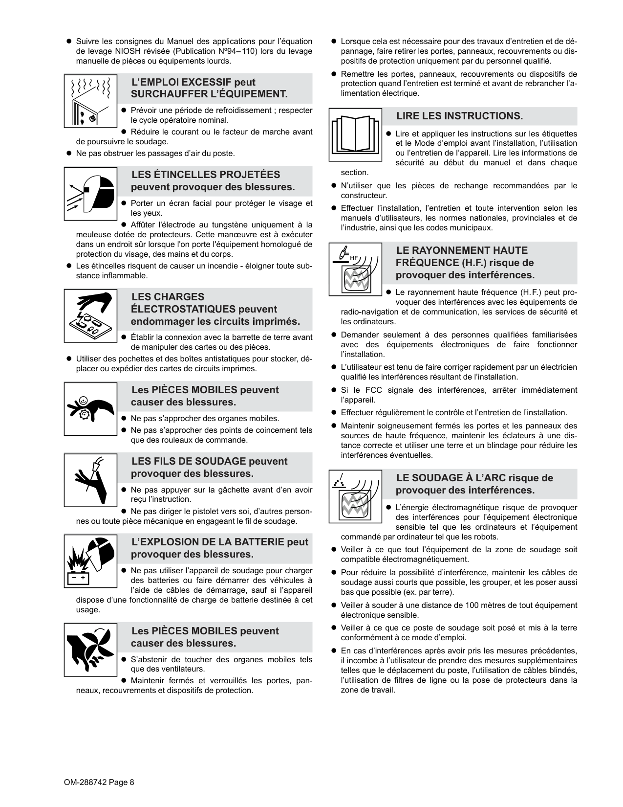
OM-288742 Page 8 l Suivre les consignes du Manuel des applications pour l’équation de levage NIOSH révisée (Publication Nº94–110) lors du levage manuelle de pièces ou équipements lourds. L’EMPLOI EXCESSIF peut
Surchauffer L’Équipement.
l Prévoir une période de refroidissement ; respecter le cycle opératoire nominal. l Réduire le courant ou le facteur de marche avant de poursuivre le soudage. l Ne pas obstruer les passages d’air du poste.Les Étincelles Projetées
peuvent provoquer des blessures. l Porter un écran facial pour protéger le visage et les yeux. l Affûter l'électrode au tungstène uniquement à la meuleuse dotée de protecteurs. Cette manœuvre est à exécuter dans un endroit sûr lorsque l'on porte l'équipement homologué de protection du visage, des mains et du corps. l Les étincelles risquent de causer un incendie - éloigner toute sub- stance inflammable.Les Charges
ÉLECTROSTATIQUES peuvent endommager les circuits imprimés. l Établir la connexion avec la barrette de terre avant de manipuler des cartes ou des pièces. l Utiliser des pochettes et des boîtes antistatiques pour stocker, dé- placer ou expédier des cartes de circuits imprimes. Les PIÈCES MOBILES peuvent causer des blessures. l Ne pas s’approcher des organes mobiles. l Ne pas s’approcher des points de coincement tels que des rouleaux de commande. LES FILS DE SOUDAGE peuvent provoquer des blessures. l Ne pas appuyer sur la gâchette avant d’en avoir reçu l’instruction. l Ne pas diriger le pistolet vers soi, d’autres person- nes ou toute pièce mécanique en engageant le fil de soudage. L’EXPLOSION DE LA BATTERIE peut provoquer des blessures. l Ne pas utiliser l’appareil de soudage pour charger des batteries ou faire démarrer des véhicules à l’aide de câbles de démarrage, sauf si l’appareil dispose d’une fonctionnalité de charge de batterie destinée à cet usage. Les PIÈCES MOBILES peuvent causer des blessures. l S’abstenir de toucher des organes mobiles tels que des ventilateurs. l Maintenir fermés et verrouillés les portes, pan- neaux, recouvrements et dispositifs de protection. l Lorsque cela est nécessaire pour des travaux d’entretien et de dé- pannage, faire retirer les portes, panneaux, recouvrements ou dis- positifs de protection uniquement par du personnel qualifié. l Remettre les portes, panneaux, recouvrements ou dispositifs de protection quand l’entretien est terminé et avant de rebrancher l’a- limentation électrique.Lire Les Instructions.
l Lire et appliquer les instructions sur les étiquettes et le Mode d’emploi avant l’installation, l’utilisation ou l’entretien de l’appareil. Lire les informations de sécurité au début du manuel et dans chaque section. l N’utiliser que les pièces de rechange recommandées par le constructeur. l Effectuer l’installation, l’entretien et toute intervention selon les manuels d’utilisateurs, les normes nationales, provinciales et de l’industrie, ainsi que les codes municipaux.Le Rayonnement Haute
FRÉQUENCE (H.F.) risque de provoquer des interférences. l Le rayonnement haute fréquence (H.F.) peut pro- voquer des interférences avec les équipements de radio-navigation et de communication, les services de sécurité et les ordinateurs. l Demander seulement à des personnes qualifiées familiarisées avec des équipements électroniques de faire fonctionner l’installation. l L’utilisateur est tenu de faire corriger rapidement par un électricien qualifié les interférences résultant de l’installation. l Si le FCC signale des interférences, arrêter immédiatement l’appareil. l Effectuer régulièrement le contrôle et l’entretien de l’installation. l Maintenir soigneusement fermés les portes et les panneaux des sources de haute fréquence, maintenir les éclateurs à une dis- tance correcte et utiliser une terre et un blindage pour réduire les interférences éventuelles. LE SOUDAGE À L’ARC risque de provoquer des interférences. l L’énergie électromagnétique risque de provoquer des interférences pour l’équipement électronique sensible tel que les ordinateurs et l’équipement commandé par ordinateur tel que les robots. l Veiller à ce que tout l’équipement de la zone de soudage soit compatible électromagnétiquement. l Pour réduire la possibilité d’interférence, maintenir les câbles de soudage aussi courts que possible, les grouper, et les poser aussi bas que possible (ex. par terre). l Veiller à souder à une distance de 100 mètres de tout équipement électronique sensible. l Veiller à ce que ce poste de soudage soit posé et mis à la terre conformément à ce mode d’emploi. l En cas d’interférences après avoir pris les mesures précédentes, il incombe à l’utilisateur de prendre des mesures supplémentaires telles que le déplacement du poste, l’utilisation de câbles blindés, l’utilisation de filtres de ligne ou la pose de protecteurs dans la zone de travail.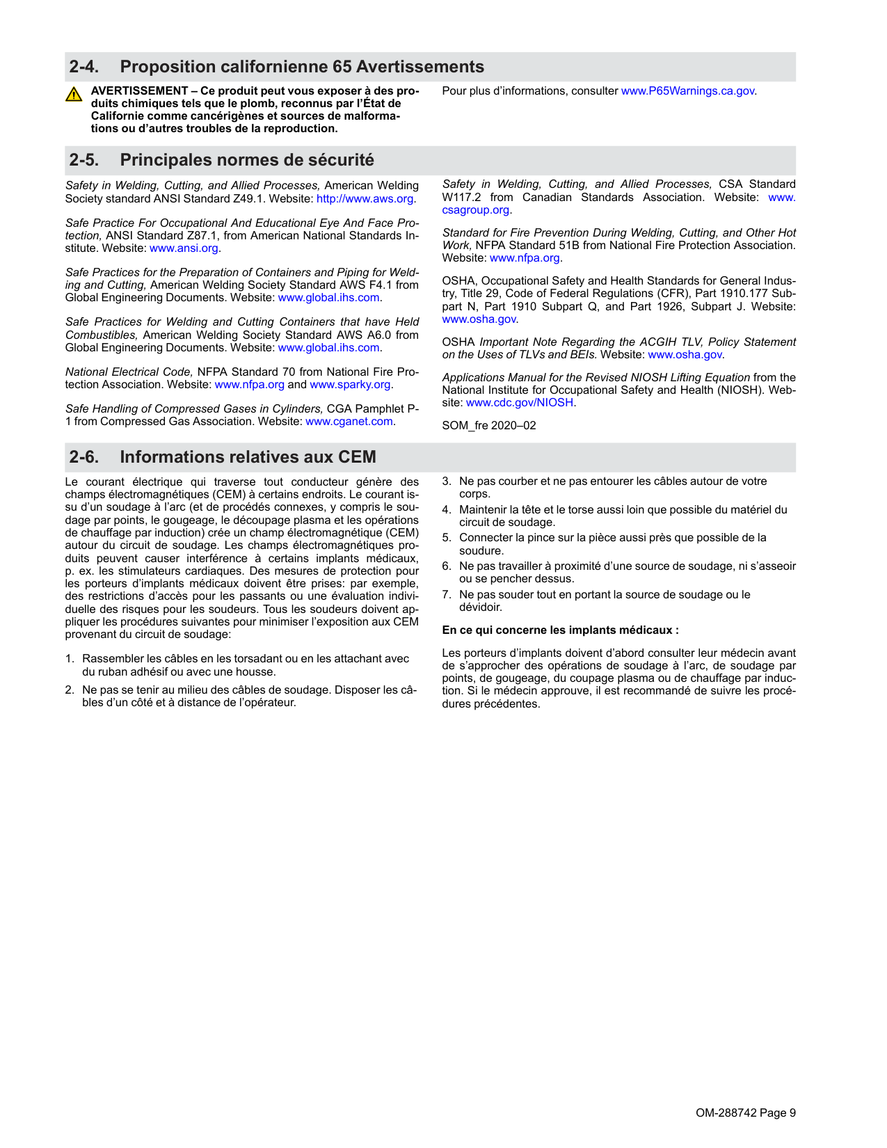
OM-288742 Page 9 2-4. Proposition californienne 65 Avertissements AVERTISSEMENT – Ce produit peut vous exposer à des pro- duits chimiques tels que le plomb, reconnus par l’État de Californie comme cancérigènes et sources de malforma- tions ou d’autres troubles de la reproduction. Pour plus d’informations, consulter www.P65Warnings.ca.gov. 2-5. Principales normes de sécurité Safety in Welding, Cutting, and Allied Processes, American Welding Society standard ANSI Standard Z49.1. Website: http://www.aws.org. Safe Practice For Occupational And Educational Eye And Face Pro- tection, ANSI Standard Z87.1, from American National Standards In- stitute. Website: www.ansi.org. Safe Practices for the Preparation of Containers and Piping for Weld- ing and Cutting, American Welding Society Standard AWS F4.1 from Global Engineering Documents. Website: www.global.ihs.com. Safe Practices for Welding and Cutting Containers that have Held Combustibles, American Welding Society Standard AWS A6.0 from Global Engineering Documents. Website: www.global.ihs.com. National Electrical Code, NFPA Standard 70 from National Fire Pro- tection Association. Website: www.nfpa.org and www.sparky.org. Safe Handling of Compressed Gases in Cylinders, CGA Pamphlet P- 1 from Compressed Gas Association. Website: www.cganet.com. Safety in Welding, Cutting, and Allied Processes, CSA Standard W117.2 from Canadian Standards Association. Website: www. csagroup.org. Standard for Fire Prevention During Welding, Cutting, and Other Hot Work, NFPA Standard 51B from National Fire Protection Association. Website: www.nfpa.org. OSHA, Occupational Safety and Health Standards for General Indus- try, Title 29, Code of Federal Regulations (CFR), Part 1910.177 Sub- part N, Part 1910 Subpart Q, and Part 1926, Subpart J. Website: www.osha.gov. OSHA Important Note Regarding the ACGIH TLV, Policy Statement on the Uses of TLVs and BEIs. Website: www.osha.gov. Applications Manual for the Revised NIOSH Lifting Equation from the National Institute for Occupational Safety and Health (NIOSH). Web- site: www.cdc.gov/NIOSH. SOM_fre 2020–02 2-6. Informations relatives aux CEM Le courant électrique qui traverse tout conducteur génère des champs électromagnétiques (CEM) à certains endroits. Le courant is- su d’un soudage à l’arc (et de procédés connexes, y compris le sou- dage par points, le gougeage, le découpage plasma et les opérations de chauffage par induction) crée un champ électromagnétique (CEM) autour du circuit de soudage. Les champs électromagnétiques pro- duits peuvent causer interférence à certains implants médicaux, p. ex. les stimulateurs cardiaques. Des mesures de protection pour les porteurs d’implants médicaux doivent être prises: par exemple, des restrictions d’accès pour les passants ou une évaluation indivi- duelle des risques pour les soudeurs. Tous les soudeurs doivent ap- pliquer les procédures suivantes pour minimiser l’exposition aux CEM provenant du circuit de soudage:
OM-288742 Page 10 F Complete Parts List is available at www.MillerWelds.com
Section 3 – Definitions
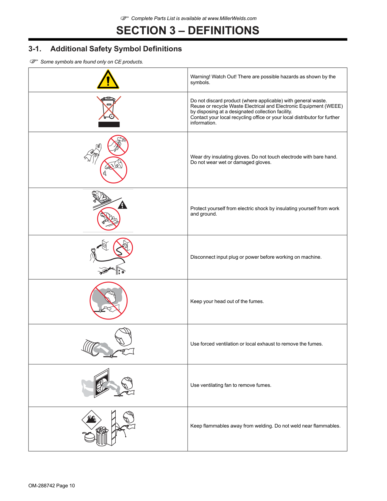
3-1. Additional Safety Symbol Definitions F Some symbols are found only on CE products. Warning! Watch Out! There are possible hazards as shown by the symbols. Do not discard product (where applicable) with general waste. Reuse or recycle Waste Electrical and Electronic Equipment (WEEE) by disposing at a designated collection facility. Contact your local recycling office or your local distributor for further information. Wear dry insulating gloves. Do not touch electrode with bare hand. Do not wear wet or damaged gloves. Protect yourself from electric shock by insulating yourself from work and ground. Disconnect input plug or power before working on machine. Keep your head out of the fumes. Use forced ventilation or local exhaust to remove the fumes. Use ventilating fan to remove fumes. Keep flammables away from welding. Do not weld near flammables.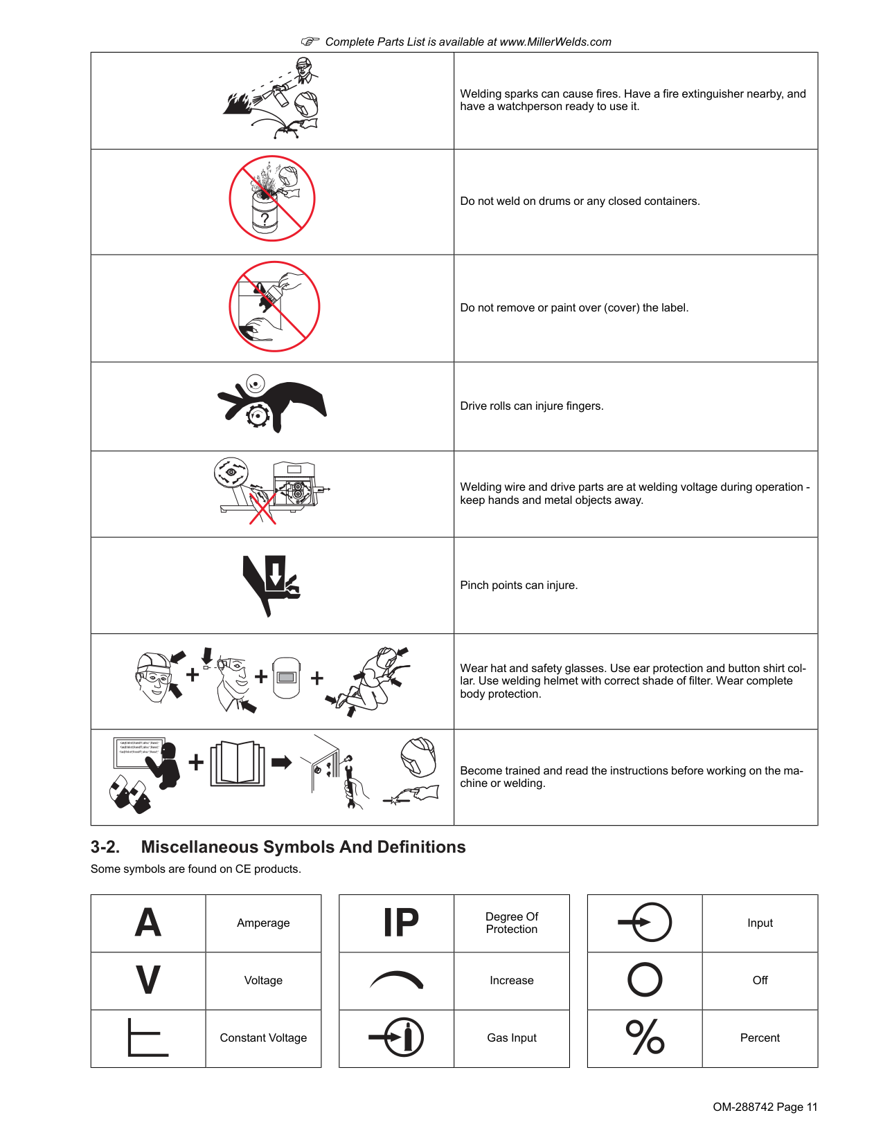
OM-288742 Page 11 F Complete Parts List is available at www.MillerWelds.com Welding sparks can cause fires. Have a fire extinguisher nearby, and have a watchperson ready to use it. Do not weld on drums or any closed containers. Do not remove or paint over (cover) the label. Drive rolls can injure fingers. Welding wire and drive parts are at welding voltage during operation - keep hands and metal objects away. Pinch points can injure. Wear hat and safety glasses. Use ear protection and button shirt col- lar. Use welding helmet with correct shade of filter. Wear complete body protection. Become trained and read the instructions before working on the ma- chine or welding. 3-2. Miscellaneous Symbols And Definitions Some symbols are found on CE products. Amperage Voltage Constant Voltage Degree Of Protection Increase Gas Input Input Off Percent
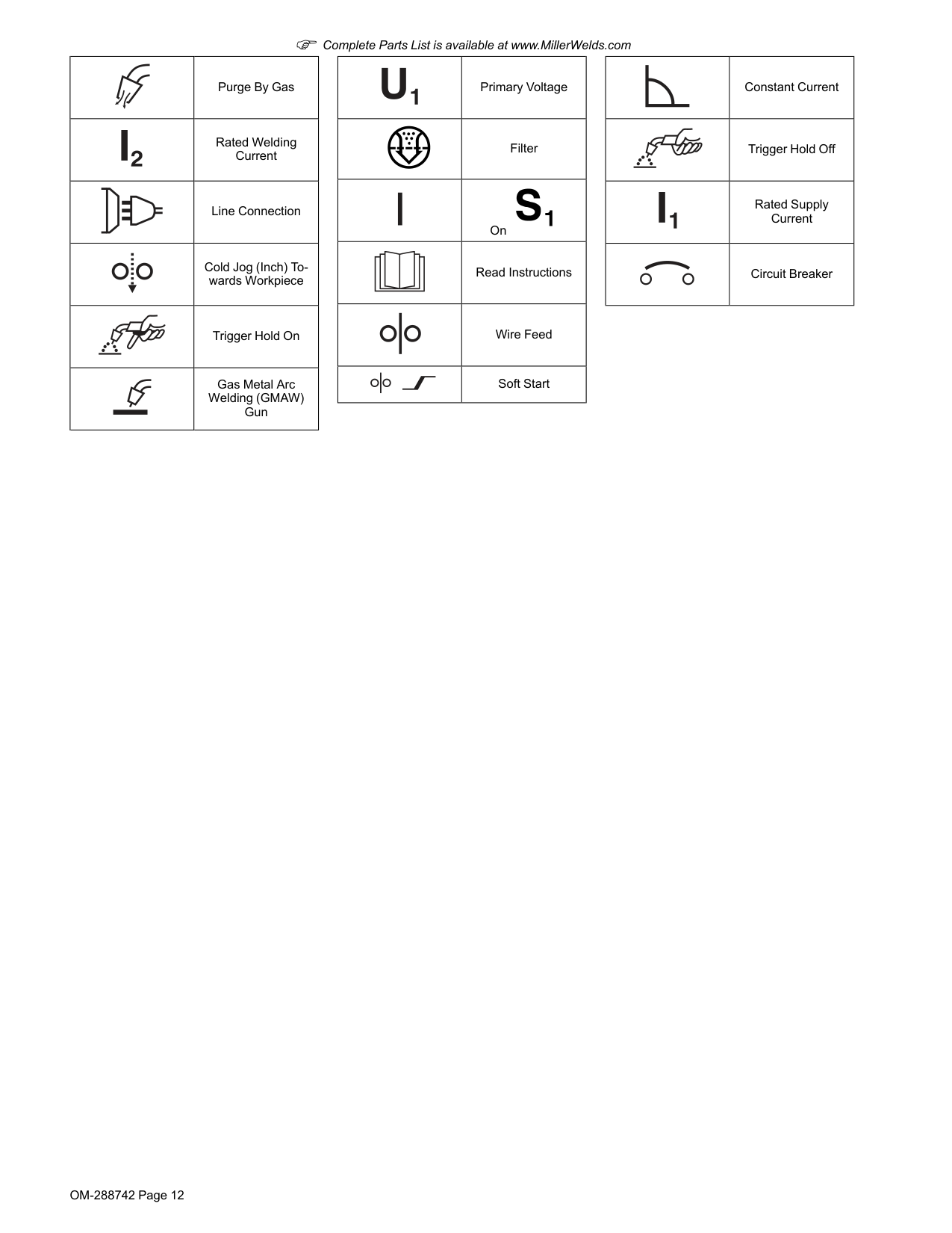
OM-288742 Page 12 F Complete Parts List is available at www.MillerWelds.com Purge By Gas Rated Welding Current Line Connection Cold Jog (Inch) To- wards Workpiece Trigger Hold On Gas Metal Arc Welding (GMAW) Gun Primary Voltage Filter On Read Instructions Wire Feed Soft Start Constant Current Trigger Hold Off Rated Supply Current Circuit Breaker
OM-288742 Page 13 F Complete Parts List is available at www.MillerWelds.com
Section 4 – Specifications
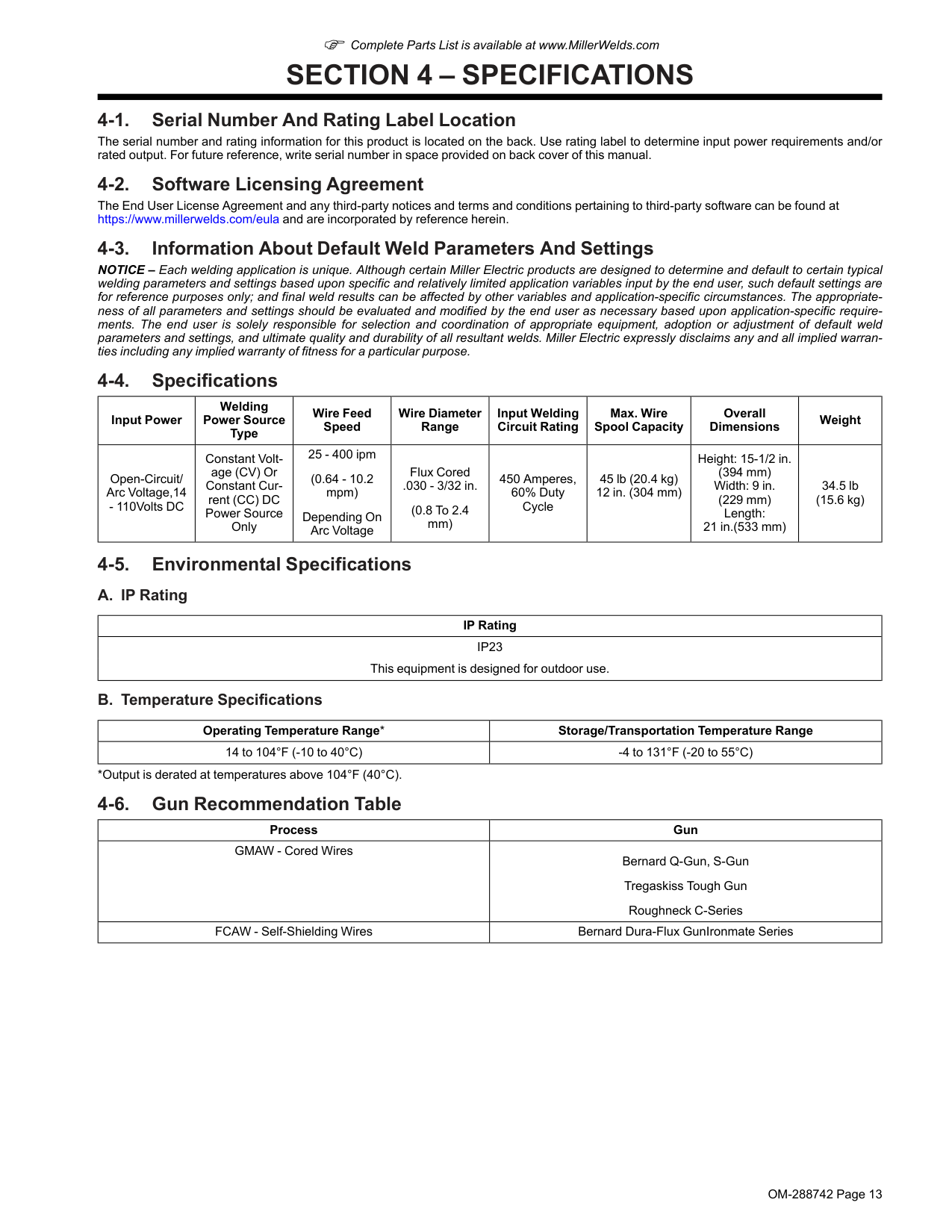
4-1. Serial Number And Rating Label Location The serial number and rating information for this product is located on the back. Use rating label to determine input power requirements and/or rated output. For future reference, write serial number in space provided on back cover of this manual. 4-2. Software Licensing Agreement The End User License Agreement and any third-party notices and terms and conditions pertaining to third-party software can be found at https://www.millerwelds.com/eula and are incorporated by reference herein. 4-3. Information About Default Weld Parameters And Settings NOTICE – Each welding application is unique. Although certain Miller Electric products are designed to determine and default to certain typical welding parameters and settings based upon specific and relatively limited application variables input by the end user, such default settings are for reference purposes only; and final weld results can be affected by other variables and application-specific circumstances. The appropriate- ness of all parameters and settings should be evaluated and modified by the end user as necessary based upon application-specific require- ments. The end user is solely responsible for selection and coordination of appropriate equipment, adoption or adjustment of default weld parameters and settings, and ultimate quality and durability of all resultant welds. Miller Electric expressly disclaims any and all implied warran- ties including any implied warranty of fitness for a particular purpose. 4-4. Specifications Input Power Welding Power Source Type Wire Feed Speed Wire Diameter Range Input Welding Circuit Rating Max. Wire Spool Capacity Overall Dimensions Weight Open-Circuit/ Arc Voltage,14Ip23
This equipment is designed for outdoor use. B. Temperature Specifications Operating Temperature Range* Storage/Transportation Temperature Range 14 to 104°F (-10 to 40°C) -4 to 131°F (-20 to 55°C) *Output is derated at temperatures above 104°F (40°C). 4-6. Gun Recommendation Table Process Gun GMAW - Cored Wires Bernard Q-Gun, S-Gun Tregaskiss Tough Gun Roughneck C-Series FCAW - Self-Shielding Wires Bernard Dura-Flux GunIronmate Series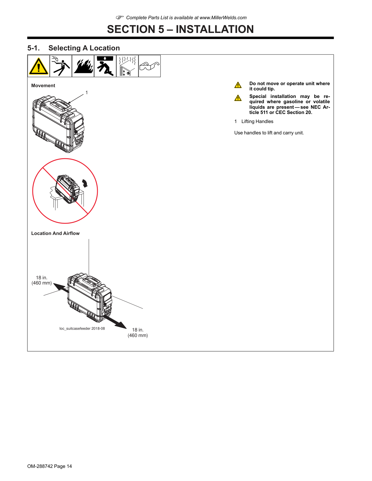
OM-288742 Page 14 F Complete Parts List is available at www.MillerWelds.com
Section 5 – Installation
5-1. Selecting A Location Movement 1 Location And Airflow 18 in. (460 mm) 18 in. (460 mm) loc_suitcasefeeder 2018-08 Do not move or operate unit where it could tip. Special installation may be re- quired where gasoline or volatile liquids are present — see NEC Ar- ticle 511 or CEC Section 20. 1 Lifting Handles Use handles to lift and carry unit.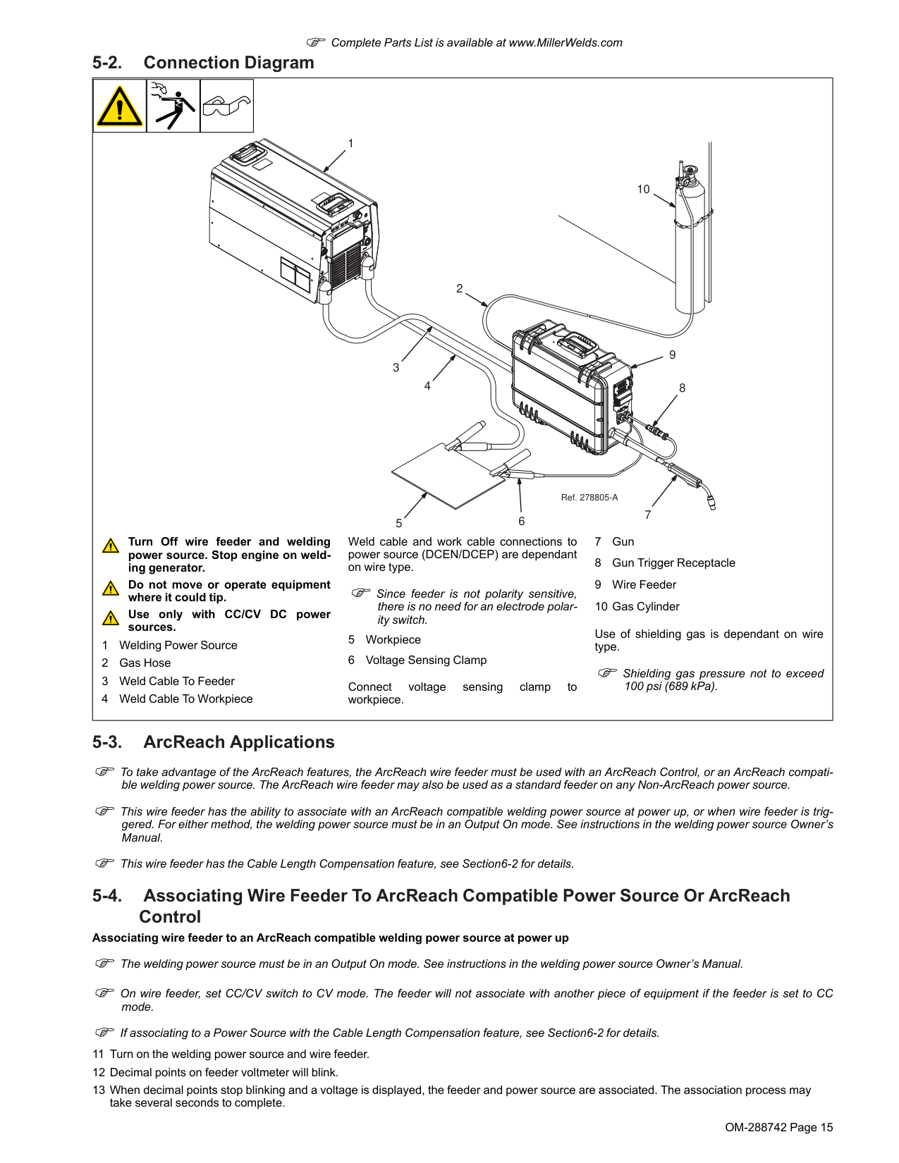
OM-288742 Page 15 F Complete Parts List is available at www.MillerWelds.com 5-2. Connection Diagram 4 5 9 2 10 7 8 6 1 3 Ref. 278805-A Turn Off wire feeder and welding power source. Stop engine on weld- ing generator. Do not move or operate equipment where it could tip. Use only with CC/CV DC power sources. 1 Welding Power Source 2 Gas Hose 3 Weld Cable To Feeder 4 Weld Cable To Workpiece Weld cable and work cable connections to power source (DCEN/DCEP) are dependant on wire type. F Since feeder is not polarity sensitive, there is no need for an electrode polar- ity switch. 5 Workpiece 6 Voltage Sensing Clamp Connect voltage sensing clamp to workpiece. 7 Gun 8 Gun Trigger Receptacle 9 Wire Feeder 10 Gas Cylinder Use of shielding gas is dependant on wire type. F Shielding gas pressure not to exceed 100 psi (689 kPa). 5-3. ArcReach Applications F To take advantage of the ArcReach features, the ArcReach wire feeder must be used with an ArcReach Control, or an ArcReach compati- ble welding power source. The ArcReach wire feeder may also be used as a standard feeder on any Non-ArcReach power source. F This wire feeder has the ability to associate with an ArcReach compatible welding power source at power up, or when wire feeder is trig- gered. For either method, the welding power source must be in an Output On mode. See instructions in the welding power source Owner’s Manual. F This wire feeder has the Cable Length Compensation feature, see Section6-2 for details. 5-4. Associating Wire Feeder To ArcReach Compatible Power Source Or ArcReach Control Associating wire feeder to an ArcReach compatible welding power source at power up F The welding power source must be in an Output On mode. See instructions in the welding power source Owner’s Manual. F On wire feeder, set CC/CV switch to CV mode. The feeder will not associate with another piece of equipment if the feeder is set to CC mode. F If associating to a Power Source with the Cable Length Compensation feature, see Section6-2 for details. 11 Turn on the welding power source and wire feeder. 12 Decimal points on feeder voltmeter will blink. 13 When decimal points stop blinking and a voltage is displayed, the feeder and power source are associated. The association process may take several seconds to complete.
OM-288742 Page 16 F Complete Parts List is available at www.MillerWelds.com 14 Dependent on the capabilities of the ArcReach power source, the feeder may set the mode switch to the correct wire mode. The wire mode is determined by the polarity of the connections to the feeder. 15 Use voltage control on feeder to adjust preset weld voltage. 16 The voltmeter on the feeder will display preset weld voltage while idle or weld voltage while welding. Associating wire feeder to an ArcReach compatible welding power source or ArcReach Control when the wire feeder is triggered F The welding power source must be in an Output On mode. See instructions in the welding power source Owner’s Manual. F On wire feeder, set CC/CV switch to CV mode. The feeder will not associate with another piece of equipment if the feeder is set to CC mode. 1 Turn on the welding power source and wire feeder. The wire feeder voltage display will alternate between three dashes and open circuit voltage. 2 Pull trigger on gun. Do not strike an arc. 3 Decimal points on feeder voltmeter will blink. 4 When decimal points stop blinking and a voltage is displayed, the feeder and power source or ArcReach Control are associated. Release trig- ger on gun. The association process may take several seconds to complete. 5 Dependent on the capabilities of the ArcReach power source, the feeder may set the mode switch to the correct wire mode. The wire mode is determined by the polarity of the connections to the feeder. 6 Use voltage control on feeder to adjust preset weld voltage. 7 The voltmeter on the feeder will display preset voltage while idle or weld voltage while welding. 5-5. Equipment Setup F To take advantage of the ArcReach features, the ArcReach wire feeder must be used with an ArcReach Control, or an ArcReach compati- ble welding power source. The ArcReach wire feeder may also be used as a standard feeder on any Non-ArcReach power source. During ArcReach operation, weld voltage and wire feed speed are set at the wire feeder front panel. Voltage control is disabled at the welding power source. Using the ArcReach wire feeder with an ArcReach compatible welding power source or ArcReach Control 8 For the wire feeder to control the welding power source, the wire feeder and power source, or wire feeder and ArcReach Control must be as- sociated. If the wire feeder is not associated to the welding power source or ArcReach Control, the wire feeder will try to associate to a weld- ing power source or ArcReach Control when the trigger is pulled. See Section5-4 to associate the wire feeder to an ArcReach compatible power source or ArcReach control. 9 When association is complete, the voltage display on the wire feeder will display preset voltage. The preset voltages of the wire feeder and the welding power source should be within 0.5 volts of each other. 10 While adjusting the voltage control on the feeder, the voltage display will show preset voltage. 11 While welding, the welding power source will display weld voltage at the studs of the welding power source. The wire feeder displays weld voltage at the wire feeder. 12 While welding, due to the voltage drops in the weld cable, the voltage display at the wire feeder and the voltage display at the welding power source will not match. The preset voltage at the wire feeder must be set to a higher value to compensate for the voltage drop of the weld ca- ble. Example: if welding voltage of 18 volts is desired at the wire feeder and there is a 4 volt drop in the weld cable, the preset voltage at the wire feeder should be 22 volts (18V + 4V = 22V). 13 When the wire feeder and welding power source or ArcReach Control are associated, they will stay associated until either unit is turned off. The wire feeder can lose power for up to ten seconds and still recover its association with the welding power source or ArcReach Control. This is for situations where the wire feeder may momentarily lose power due to a prolonged short circuit condition in the welding process. 14 If the CC/CV switch on the feeder is changed to CC mode, the feeder will lose its association with the welding power source or ArcReach Control. To re-establish the association, set switch to CV mode and restart the association process. Using the ArcReach wire feeder with a Non-ArcReach compatible welding power source 1 The wire feeder may be used with any constant voltage (CV) or constant current (CC) DC welding power source. 2 Set CC/CV switch in feeder to match output of power source. 3 The wire feeder will automatically work on a non-ArcReach compatible welding power source. There are no switches or jumpers to change. 4 The ArcReach features will not be available. 5 The voltage knob on front panel will be non-functional. 6 If the feeder is set to CC, the voltage display on the wire feeder will display CC when not welding. 7 While welding, the voltage display on the wire feeder will display weld voltage at the wire feeder.
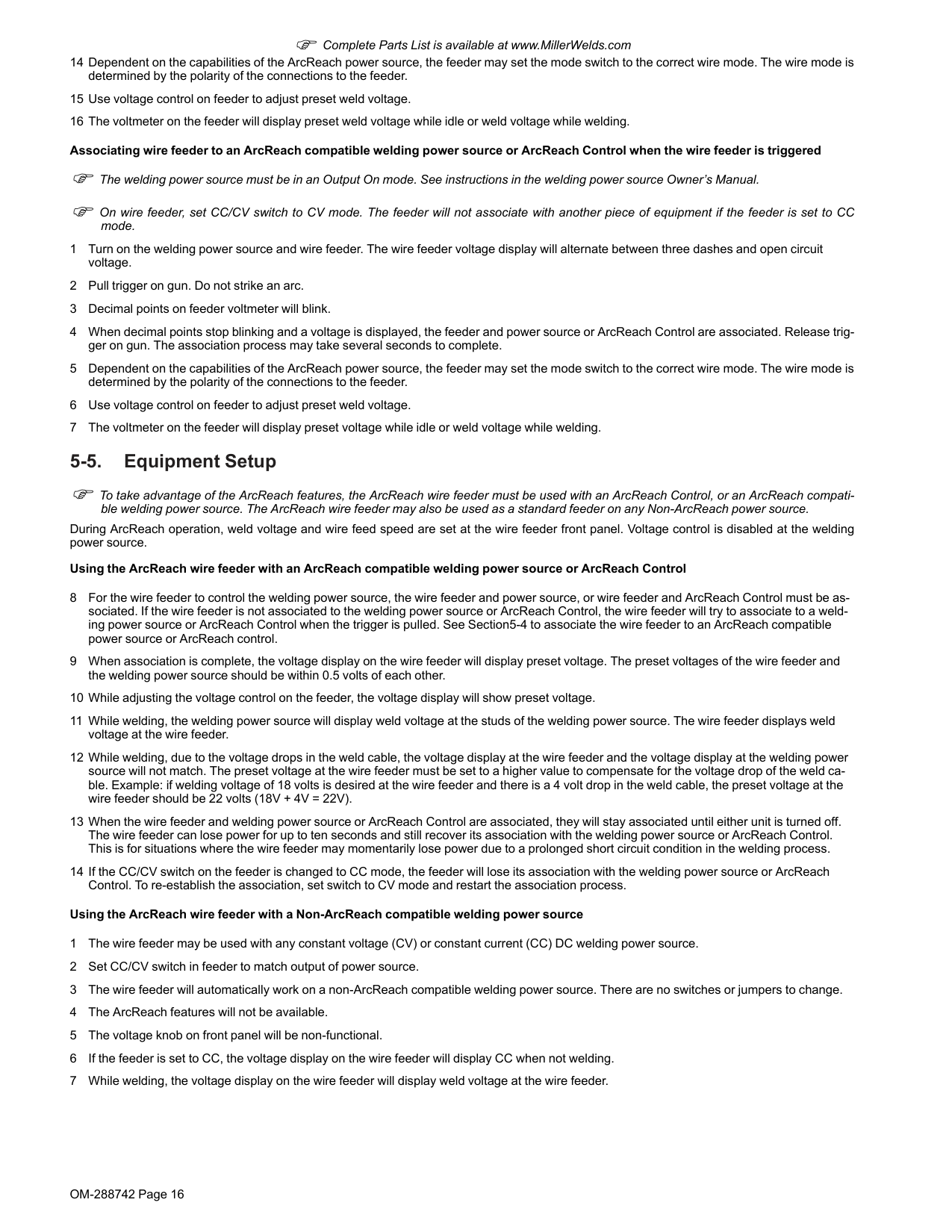
OM-288742 Page 17 F Complete Parts List is available at www.MillerWelds.com 5-6. Installing Drive Rolls 3 1 2
257817-B
Installing Drive Rolls: 1 Drive Securing Roll Nut 2 Drive Roll Carrier Turn nut one click until lobes of nut line up with lobes of drive roll carrier. 3 Drive Roll Slide drive roll onto drive roll carrier. Turn nut one click. Repeat procedure for top drive roll. Cleaning Drive Rolls: Remove drive rolls, and clean grooves using a wire brush.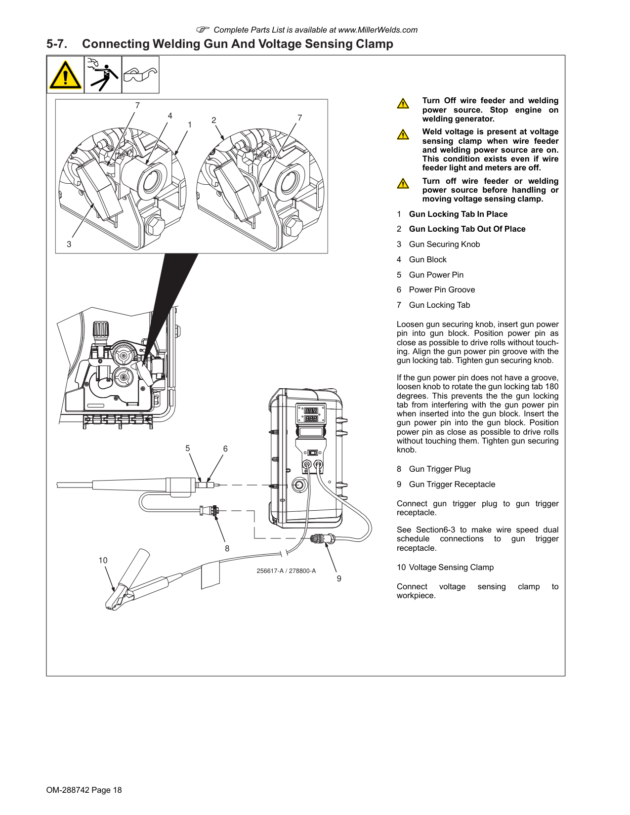
OM-288742 Page 18 F Complete Parts List is available at www.MillerWelds.com 5-7. Connecting Welding Gun And Voltage Sensing Clamp
256617-A / 278800-A
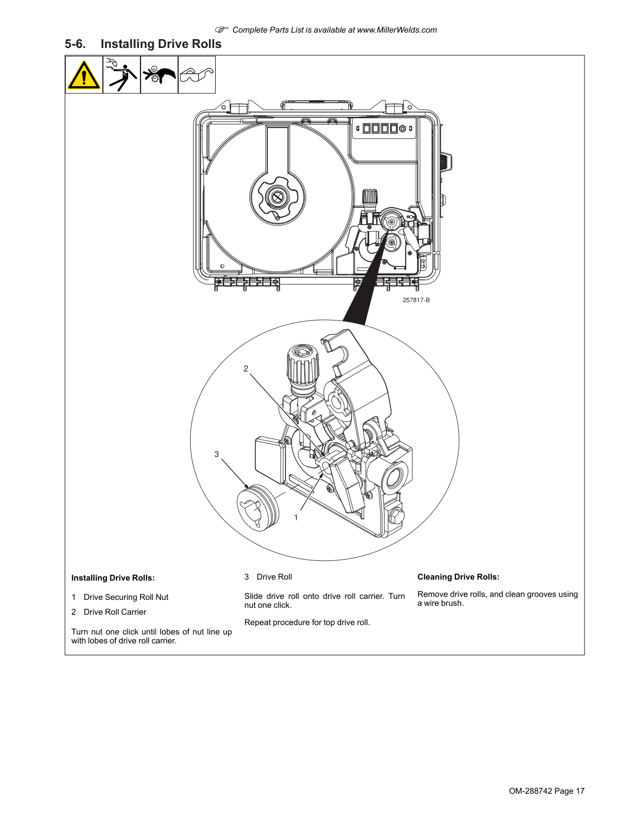
5 8 9 10 7 7 6 4 1 3 2 Turn Off wire feeder and welding power source. Stop engine on welding generator. Weld voltage is present at voltage sensing clamp when wire feeder and welding power source are on. This condition exists even if wire feeder light and meters are off. Turn off wire feeder or welding power source before handling or moving voltage sensing clamp. 1 Gun Locking Tab In Place 2 Gun Locking Tab Out Of Place 3 Gun Securing Knob 4 Gun Block 5 Gun Power Pin 6 Power Pin Groove 7 Gun Locking Tab Loosen gun securing knob, insert gun power pin into gun block. Position power pin as close as possible to drive rolls without touch- ing. Align the gun power pin groove with the gun locking tab. Tighten gun securing knob. If the gun power pin does not have a groove, loosen knob to rotate the gun locking tab 180 degrees. This prevents the the gun locking tab from interfering with the gun power pin when inserted into the gun block. Insert the gun power pin into the gun block. Position power pin as close as possible to drive rolls without touching them. Tighten gun securing knob. 8 Gun Trigger Plug 9 Gun Trigger Receptacle Connect gun trigger plug to gun trigger receptacle. See Section6-3 to make wire speed dual schedule connections to gun trigger receptacle. 10 Voltage Sensing Clamp Connect voltage sensing clamp to workpiece.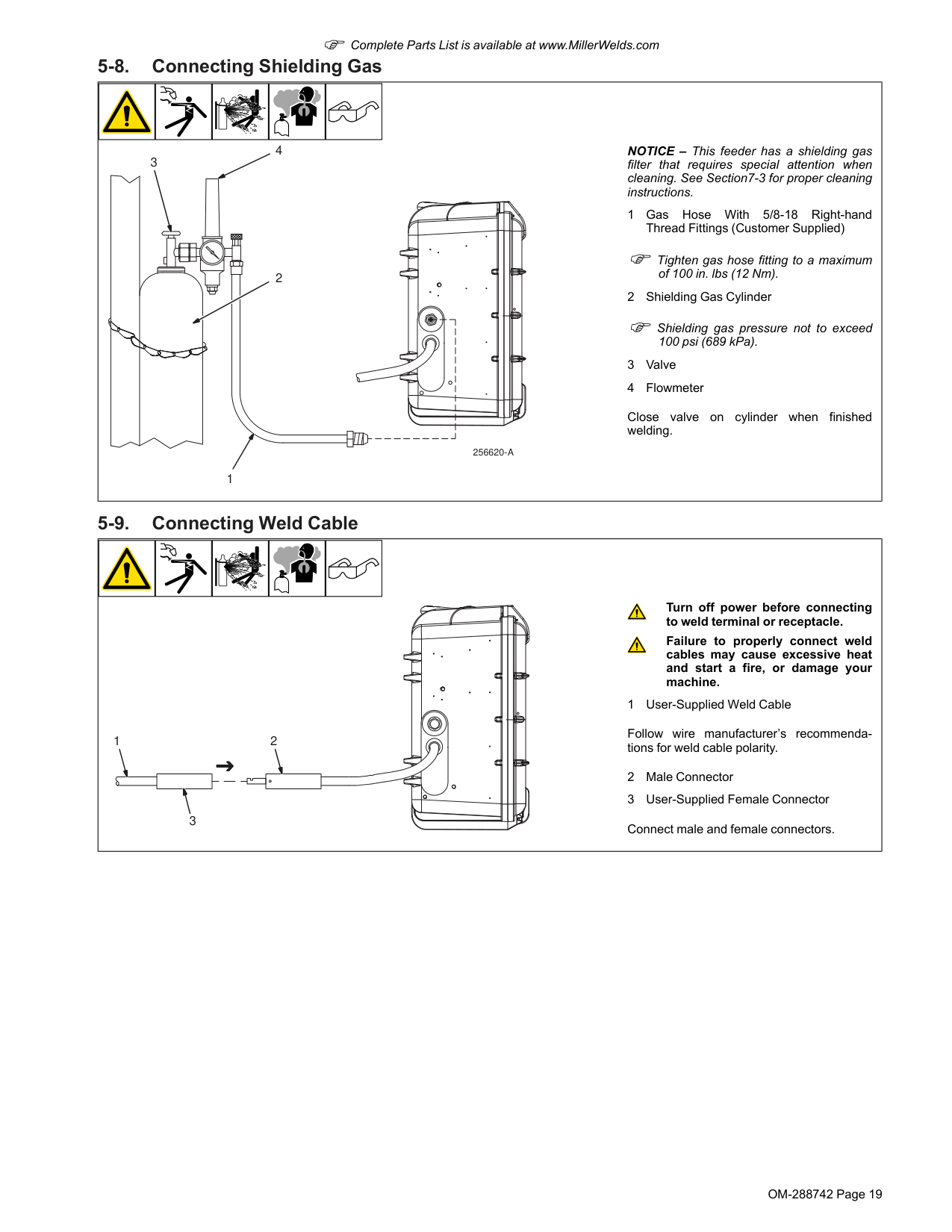
OM-288742 Page 19 F Complete Parts List is available at www.MillerWelds.com 5-8. Connecting Shielding Gas 1 3 4
256620-A
2 NOTICE – This feeder has a shielding gas filter that requires special attention when cleaning. See Section7-3 for proper cleaning instructions. 1 Gas Hose With 5/8-18 Right-hand Thread Fittings (Customer Supplied) F Tighten gas hose fitting to a maximum of 100 in. lbs (12 Nm). 2 Shielding Gas Cylinder F Shielding gas pressure not to exceed 100 psi (689 kPa). 3 Valve 4 Flowmeter Close valve on cylinder when finished welding. 5-9. Connecting Weld Cable 2 3 1 Turn off power before connecting to weld terminal or receptacle. Failure to properly connect weld cables may cause excessive heat and start a fire, or damage your machine. 1 User-Supplied Weld Cable Follow wire manufacturer’s recommenda- tions for weld cable polarity. 2 Male Connector 3 User-Supplied Female Connector Connect male and female connectors.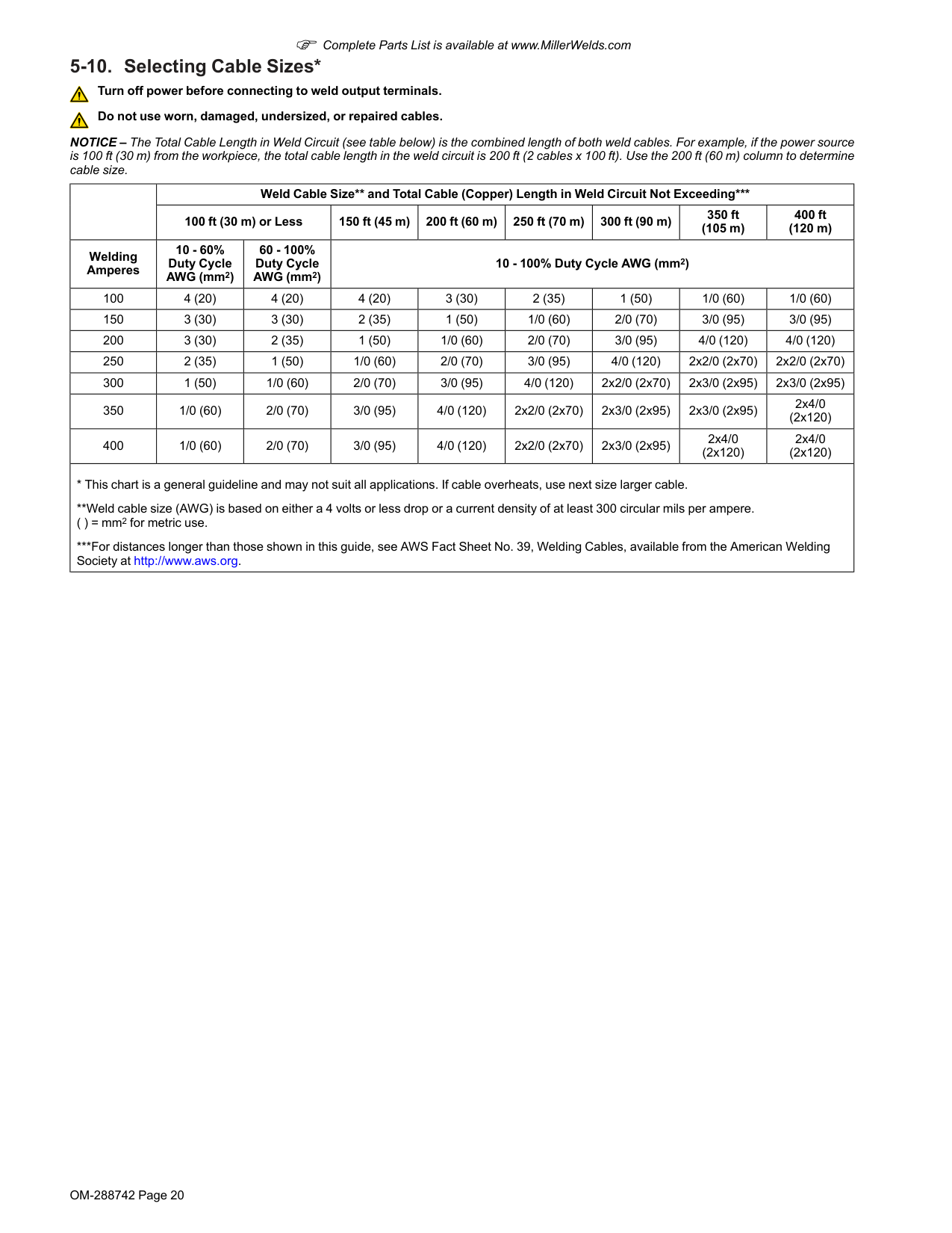
OM-288742 Page 20 F Complete Parts List is available at www.MillerWelds.com 5-10. Selecting Cable Sizes* Turn off power before connecting to weld output terminals. Do not use worn, damaged, undersized, or repaired cables. NOTICE – The Total Cable Length in Weld Circuit (see table below) is the combined length of both weld cables. For example, if the power source is 100 ft (30 m) from the workpiece, the total cable length in the weld circuit is 200 ft (2 cables x 100 ft). Use the 200 ft (60 m) column to determine cable size. Weld Cable Size and Total Cable (Copper) Length in Weld Circuit Not Exceeding* 100 ft (30 m) or Less 150 ft (45 m) 200 ft (60 m) 250 ft (70 m) 300 ft (90 m) 350 ft (105 m) 400 ft (120 m) Welding Amperes 10 - 60% Duty Cycle AWG (mm2) 60 - 100% Duty Cycle AWG (mm2) 10 - 100% Duty Cycle AWG (mm2) 100 4 (20) 4 (20) 4 (20) 3 (30) 2 (35) 1 (50) 1/0 (60) 1/0 (60) 150 3 (30) 3 (30) 2 (35) 1 (50) 1/0 (60) 2/0 (70) 3/0 (95) 3/0 (95) 200 3 (30) 2 (35) 1 (50) 1/0 (60) 2/0 (70) 3/0 (95) 4/0 (120) 4/0 (120) 250 2 (35) 1 (50) 1/0 (60) 2/0 (70) 3/0 (95) 4/0 (120) 2x2/0 (2x70) 2x2/0 (2x70) 300 1 (50) 1/0 (60) 2/0 (70) 3/0 (95) 4/0 (120) 2x2/0 (2x70) 2x3/0 (2x95) 2x3/0 (2x95) 350 1/0 (60) 2/0 (70) 3/0 (95) 4/0 (120) 2x2/0 (2x70) 2x3/0 (2x95) 2x3/0 (2x95) 2x4/0 (2x120) 400 1/0 (60) 2/0 (70) 3/0 (95) 4/0 (120) 2x2/0 (2x70) 2x3/0 (2x95) 2x4/0 (2x120) 2x4/0 (2x120)
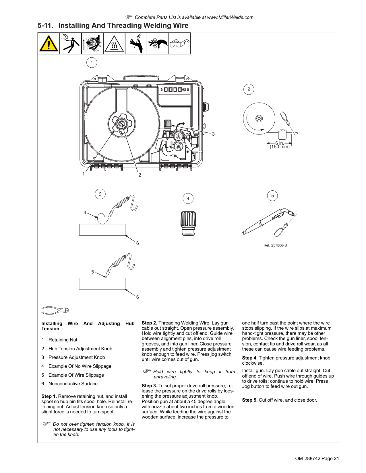
OM-288742 Page 21 F Complete Parts List is available at www.MillerWelds.com 5-11. Installing And Threading Welding Wire 1 2 3 6 in. (150 mm) 4 5 6 6 2 1 3 5 4 Ref. 257806-B Installing Wire And Adjusting Hub Tension 1 Retaining Nut 2 Hub Tension Adjustment Knob 3 Pressure Adjustment Knob 4 Example Of No Wire Slippage 5 Example Of Wire Slippage 6 Nonconductive Surface Step 1. Remove retaining nut, and install spool so hub pin fits spool hole. Reinstall re- taining nut. Adjust tension knob so only a slight force is needed to turn spool. F Do not over tighten tension knob. It is not necessary to use any tools to tight- en the knob. Step 2. Threading Welding Wire. Lay gun cable out straight. Open pressure assembly. Hold wire tightly and cut off end. Guide wire between alignment pins, into drive roll grooves, and into gun liner. Close pressure assembly and tighten pressure adjustment knob enough to feed wire. Press jog switch until wire comes out of gun. F Hold wire tightly to keep it from unraveling. Step 3. To set proper drive roll pressure, re- lease the pressure on the drive rolls by loos- ening the pressure adjustment knob. Position gun at about a 45 degree angle, with nozzle about two inches from a wooden surface. While feeding the wire against the wooden surface, increase the pressure to one half turn past the point where the wire stops slipping. If the wire slips at maximum hand-tight pressure, there may be other problems. Check the gun liner, spool ten- sion, contact tip and drive roll wear, as all these can cause wire feeding problems. Step 4. Tighten pressure adjustment knob clockwise. Install gun. Lay gun cable out straight. Cut off end of wire. Push wire through guides up to drive rolls; continue to hold wire. Press Jog button to feed wire out gun. Step 5. Cut off wire, and close door.
OM-288742 Page 22 F Complete Parts List is available at www.MillerWelds.com 5-12. Motor Board (PC1) DIP Switch Settings
Rc111
247678-B
2 3 1 1 2O P E N
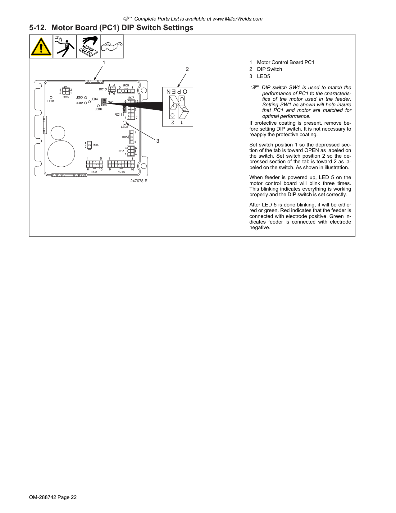
1 Motor Control Board PC1 2 DIP Switch 3Led5
F DIP switch SW1 is used to match the performance of PC1 to the characteris- tics of the motor used in the feeder. Setting SW1 as shown will help insure that PC1 and motor are matched for optimal performance. If protective coating is present, remove be- fore setting DIP switch. It is not necessary to reapply the protective coating. Set switch position 1 so the depressed sec- tion of the tab is toward OPEN as labeled on the switch. Set switch position 2 so the de- pressed section of the tab is toward 2 as la- beled on the switch. As shown in illustration. When feeder is powered up, LED 5 on the motor control board will blink three times. This blinking indicates everything is working properly and the DIP switch is set correctly. After LED 5 is done blinking, it will be either red or green. Red indicates that the feeder is connected with electrode positive. Green in- dicates feeder is connected with electrode negative.
OM-288742 Page 23
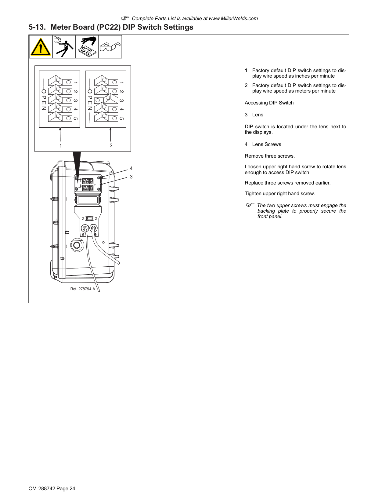
OM-288742 Page 24 F Complete Parts List is available at www.MillerWelds.com 5-13. Meter Board (PC22) DIP Switch Settings 4 3 1 2 3 4 5
O P E N
1 2 3 4 5O P E N
1 2 Ref. 278794-A 1 Factory default DIP switch settings to dis- play wire speed as inches per minute 2 Factory default DIP switch settings to dis- play wire speed as meters per minute Accessing DIP Switch 3 Lens DIP switch is located under the lens next to the displays. 4 Lens Screws Remove three screws. Loosen upper right hand screw to rotate lens enough to access DIP switch. Replace three screws removed earlier. Tighten upper right hand screw. F The two upper screws must engage the backing plate to properly secure the front panel.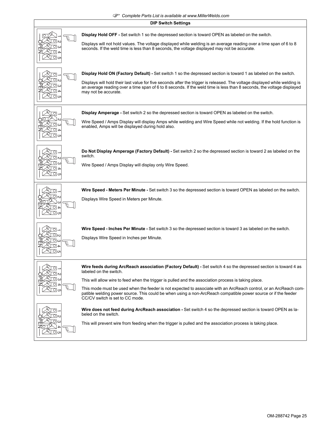
OM-288742 Page 25 F Complete Parts List is available at www.MillerWelds.com DIP Switch Settings 1 2 3 4 5
Open
Display Hold OFF - Set switch 1 so the depressed section is toward OPEN as labeled on the switch. Displays will not hold values. The voltage displayed while welding is an average reading over a time span of 6 to 8 seconds. If the weld time is less than 8 seconds, the voltage displayed may not be accurate. 1 2 3 4 5Open
Display Hold ON (Factory Default) - Set switch 1 so the depressed section is toward 1 as labeled on the switch. Displays will hold their last value for five seconds after the trigger is released. The voltage displayed while welding is an average reading over a time span of 6 to 8 seconds. If the weld time is less than 8 seconds, the voltage displayed may not be accurate. 1 2 3 4 5Open
Display Amperage - Set switch 2 so the depressed section is toward OPEN as labeled on the switch. Wire Speed / Amps Display will display Amps while welding and Wire Speed while not welding. If the hold function is enabled, Amps will be displayed during hold also. 1 2 3 4 5Open
Do Not Display Amperage (Factory Default) - Set switch 2 so the depressed section is toward 2 as labeled on the switch. Wire Speed / Amps Display will display only Wire Speed. 1 2 3 4 5Open
Wire Speed - Meters Per Minute - Set switch 3 so the depressed section is toward OPEN as labeled on the switch. Displays Wire Speed in Meters per Minute. 1 2 3 4 5Open
Wire Speed - Inches Per Minute - Set switch 3 so the depressed section is toward 3 as labeled on the switch. Displays Wire Speed in Inches per Minute. 1 2 3 4 5Open
Wire feeds during ArcReach association (Factory Default) - Set switch 4 so the depressed section is toward 4 as labeled on the switch. This will allow wire to feed when the trigger is pulled and the association process is taking place. This mode must be used when the feeder is not expected to associate with an ArcReach control, or an ArcReach com- patible welding power source. This could be when using a non-ArcReach compatible power source or if the feeder CC/CV switch is set to CC mode. 1 2 3 4 5Open
Wire does not feed during ArcReach association - Set switch 4 so the depressed section is toward OPEN as la- beled on the switch. This will prevent wire from feeding when the trigger is pulled and the association process is taking place.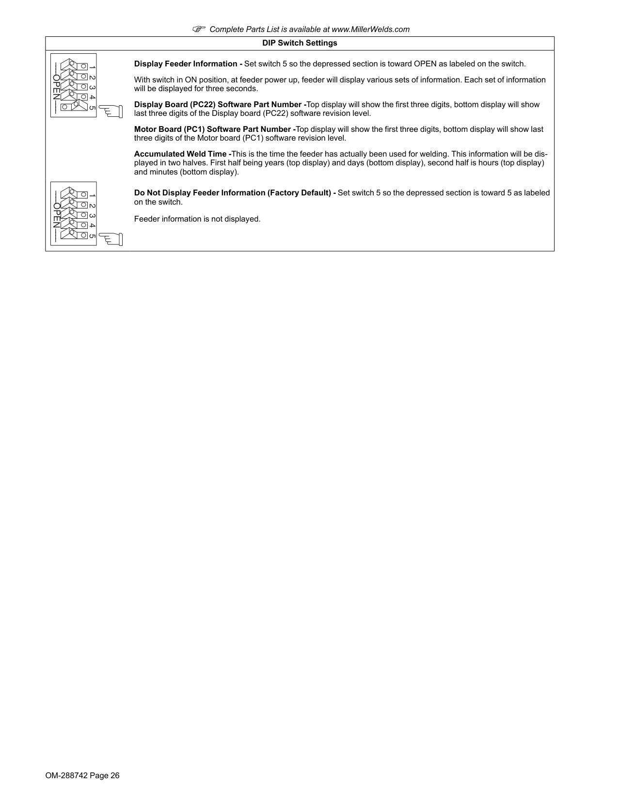
OM-288742 Page 26 F Complete Parts List is available at www.MillerWelds.com DIP Switch Settings 1 2 3 4 5
Open
Display Feeder Information - Set switch 5 so the depressed section is toward OPEN as labeled on the switch. With switch in ON position, at feeder power up, feeder will display various sets of information. Each set of information will be displayed for three seconds. Display Board (PC22) Software Part Number -Top display will show the first three digits, bottom display will show last three digits of the Display board (PC22) software revision level. Motor Board (PC1) Software Part Number -Top display will show the first three digits, bottom display will show last three digits of the Motor board (PC1) software revision level. Accumulated Weld Time -This is the time the feeder has actually been used for welding. This information will be dis- played in two halves. First half being years (top display) and days (bottom display), second half is hours (top display) and minutes (bottom display). 1 2 3 4 5Open
Do Not Display Feeder Information (Factory Default) - Set switch 5 so the depressed section is toward 5 as labeled on the switch. Feeder information is not displayed.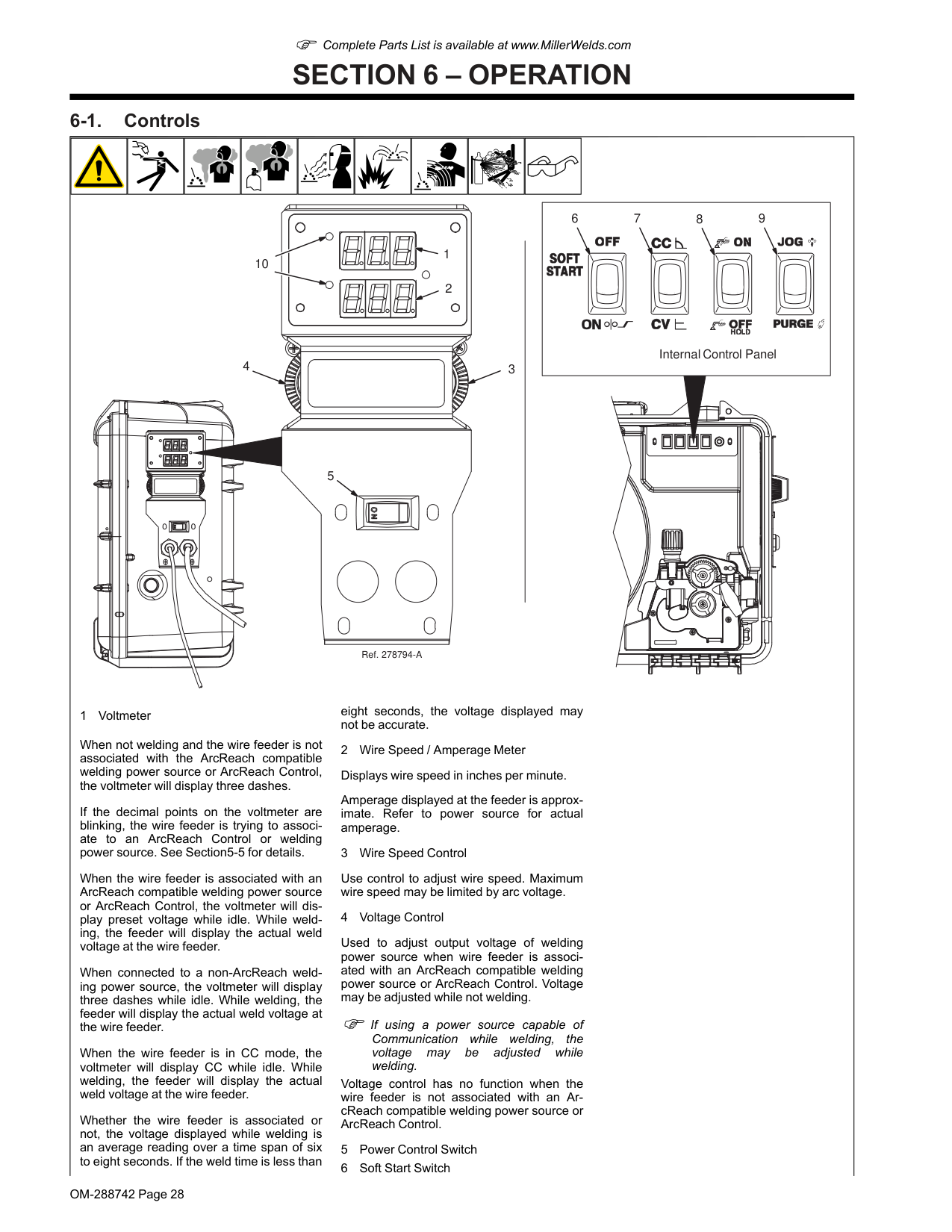
OM-288742 Page 28 F Complete Parts List is available at www.MillerWelds.com
Section 6 – Operation
6-1. Controls 9 8 7 6 Ref. 278794-A Internal Control Panel 5 2 1 4 3 10 1 Voltmeter When not welding and the wire feeder is not associated with the ArcReach compatible welding power source or ArcReach Control, the voltmeter will display three dashes. If the decimal points on the voltmeter are blinking, the wire feeder is trying to associ- ate to an ArcReach Control or welding power source. See Section5-5 for details. When the wire feeder is associated with an ArcReach compatible welding power source or ArcReach Control, the voltmeter will dis- play preset voltage while idle. While weld- ing, the feeder will display the actual weld voltage at the wire feeder. When connected to a non-ArcReach weld- ing power source, the voltmeter will display three dashes while idle. While welding, the feeder will display the actual weld voltage at the wire feeder. When the wire feeder is in CC mode, the voltmeter will display CC while idle. While welding, the feeder will display the actual weld voltage at the wire feeder. Whether the wire feeder is associated or not, the voltage displayed while welding is an average reading over a time span of six to eight seconds. If the weld time is less than eight seconds, the voltage displayed may not be accurate. 2 Wire Speed / Amperage Meter Displays wire speed in inches per minute. Amperage displayed at the feeder is approx- imate. Refer to power source for actual amperage. 3 Wire Speed Control Use control to adjust wire speed. Maximum wire speed may be limited by arc voltage. 4 Voltage Control Used to adjust output voltage of welding power source when wire feeder is associ- ated with an ArcReach compatible welding power source or ArcReach Control. Voltage may be adjusted while not welding. F If using a power source capable of Communication while welding, the voltage may be adjusted while welding. Voltage control has no function when the wire feeder is not associated with an Ar- cReach compatible welding power source or ArcReach Control. 5 Power Control Switch 6 Soft Start Switch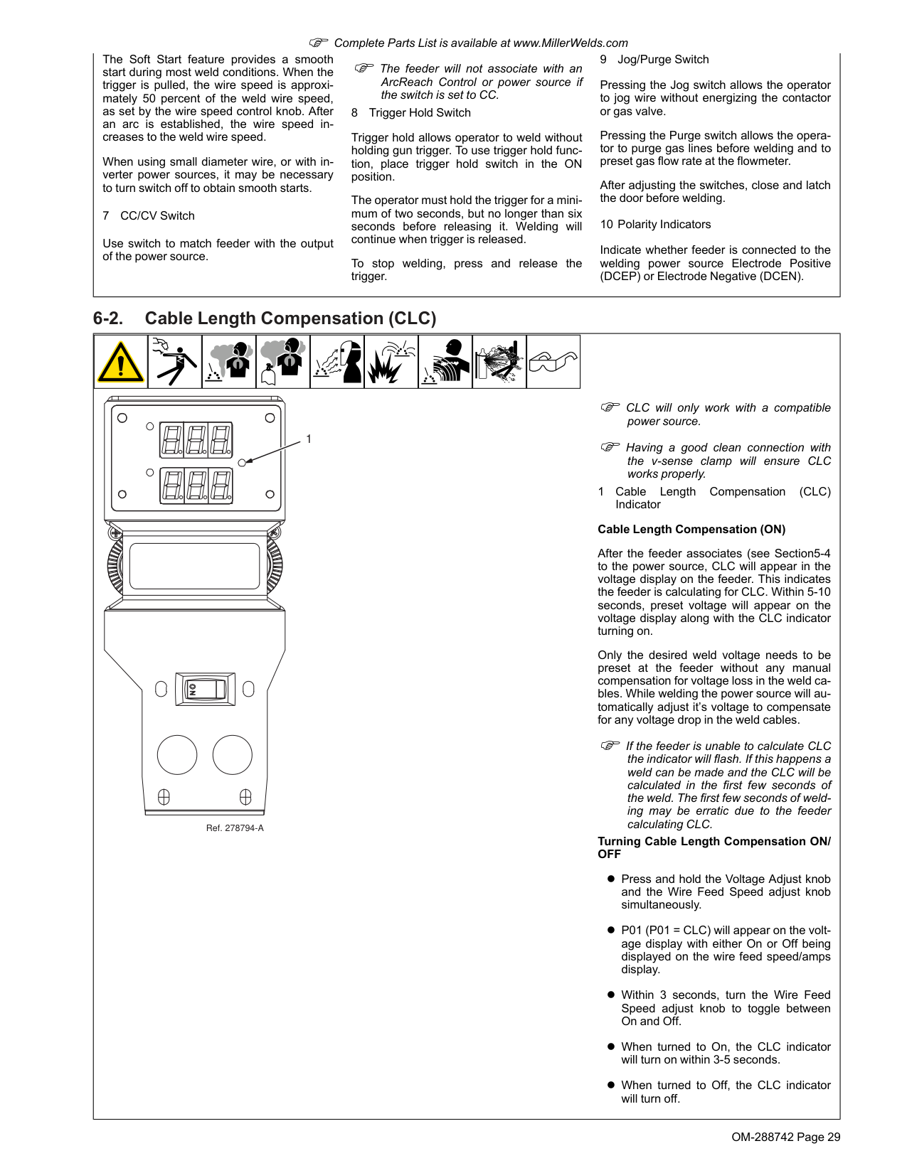
OM-288742 Page 29 F Complete Parts List is available at www.MillerWelds.com The Soft Start feature provides a smooth start during most weld conditions. When the trigger is pulled, the wire speed is approxi- mately 50 percent of the weld wire speed, as set by the wire speed control knob. After an arc is established, the wire speed in- creases to the weld wire speed. When using small diameter wire, or with in- verter power sources, it may be necessary to turn switch off to obtain smooth starts. 7 CC/CV Switch Use switch to match feeder with the output of the power source. F The feeder will not associate with an ArcReach Control or power source if the switch is set to CC. 8 Trigger Hold Switch Trigger hold allows operator to weld without holding gun trigger. To use trigger hold func- tion, place trigger hold switch in the ON position. The operator must hold the trigger for a mini- mum of two seconds, but no longer than six seconds before releasing it. Welding will continue when trigger is released. To stop welding, press and release the trigger. 9 Jog/Purge Switch Pressing the Jog switch allows the operator to jog wire without energizing the contactor or gas valve. Pressing the Purge switch allows the opera- tor to purge gas lines before welding and to preset gas flow rate at the flowmeter. After adjusting the switches, close and latch the door before welding. 10 Polarity Indicators Indicate whether feeder is connected to the welding power source Electrode Positive (DCEP) or Electrode Negative (DCEN). 6-2. Cable Length Compensation (CLC) 1 Ref. 278794-A F CLC will only work with a compatible power source. F Having a good clean connection with the v-sense clamp will ensure CLC works properly. 1 Cable Length Compensation
(Clc)
Indicator Cable Length Compensation (ON) After the feeder associates (see Section5-4 to the power source, CLC will appear in the voltage display on the feeder. This indicates the feeder is calculating for CLC. Within 5-10 seconds, preset voltage will appear on the voltage display along with the CLC indicator turning on. Only the desired weld voltage needs to be preset at the feeder without any manual compensation for voltage loss in the weld ca- bles. While welding the power source will au- tomatically adjust it’s voltage to compensate for any voltage drop in the weld cables. F If the feeder is unable to calculate CLC the indicator will flash. If this happens a weld can be made and the CLC will be calculated in the first few seconds of the weld. The first few seconds of weld- ing may be erratic due to the feeder calculating CLC. Turning Cable Length Compensation ON/Off
l Press and hold the Voltage Adjust knob and the Wire Feed Speed adjust knob simultaneously. l P01 (P01 = CLC) will appear on the volt- age display with either On or Off being displayed on the wire feed speed/amps display. l Within 3 seconds, turn the Wire Feed Speed adjust knob to toggle between On and Off. l When turned to On, the CLC indicator will turn on within 3-5 seconds. l When turned to Off, the CLC indicator will turn off.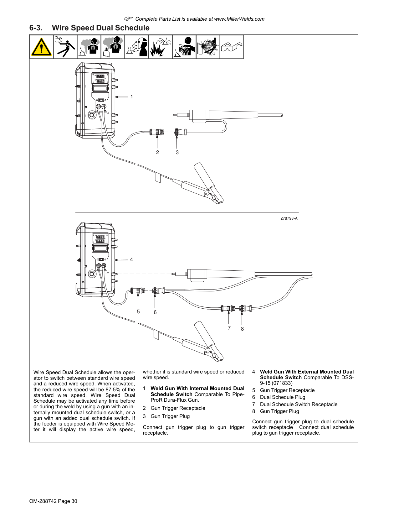
OM-288742 Page 30 F Complete Parts List is available at www.MillerWelds.com 6-3. Wire Speed Dual Schedule 3 2 6 7 8 5 1 4
278798-A
Wire Speed Dual Schedule allows the oper- ator to switch between standard wire speed and a reduced wire speed. When activated, the reduced wire speed will be 87.5% of the standard wire speed. Wire Speed Dual Schedule may be activated any time before or during the weld by using a gun with an in- ternally mounted dual schedule switch, or a gun with an added dual schedule switch. If the feeder is equipped with Wire Speed Me- ter it will display the active wire speed, whether it is standard wire speed or reduced wire speed. 1 Weld Gun With Internal Mounted Dual Schedule Switch Comparable To Pipe- ProR Dura-Flux Gun. 2 Gun Trigger Receptacle 3 Gun Trigger Plug Connect gun trigger plug to gun trigger receptacle. 4 Weld Gun With External Mounted Dual Schedule Switch Comparable To DSS- 9-15 (071833) 5 Gun Trigger Receptacle 6 Dual Schedule Plug 7 Dual Schedule Switch Receptacle 8 Gun Trigger Plug Connect gun trigger plug to dual schedule switch receptacle . Connect dual schedule plug to gun trigger receptacle.
OM-288742 Page 31 F Complete Parts List is available at www.MillerWelds.com
Section 7 – Maintenance
7-1. Routine Maintenance Disconnect power before maintaining. F Service equipment more often if used in severe conditions. ü = Check ◇= Change m = Clean ¶ = Replace Every 3 Months ¶ Unreadable Labels mWeld Terminals ü¶Weld Cords And Cables ümClean And Tighten Weld Connections ¶Damaged Gas Hose Every 6 Months m Inside Unit m Drive Rolls *To be done by Factory Authorized Service Agent. 7-2. Overload Protection And Thermostat Protection Ref. 278794-ACb1
1 Turn Off wire feeder and welding power source. Stop engine on welding generator. 1 Supplementary Protector CB1 CB1 protects wire feeder from overload. Cor- rect problem and reset CB1. Close and latch door. Thermostat Protection Unit has internal thermostat protection and will not feed wire if overheating occurs (see Section 7-4).
OM-288742 Page 32 F Complete Parts List is available at www.MillerWelds.com 7-3. Cleaning Debris From Shielding Gas Filter Fitting 1 Ref. 256623-A 3/4 in. Disconnect Power before maintaining. 1 Shielding Gas Filter Fitting Remove fitting from gas valve on back panel of feeder. Blow compressed air through the threaded male end of fitting to dislodge debris from in- ternal mesh screen. F Replace fitting if blowing compressed air through fitting does not clear obstructions. Reinstall fitting into gas valve. Tighten fitting to 250 in. lbs (28 Nm). 7-4. Troubleshooting Trouble Remedy Wire does not feed; open-circuit volt- age available. Check power switch S1 and connections, replace if necessary. Check supplementary protector CB1. Reset CB1. Unit overheated. Allow unit to cool. Check sensing lead connection. Check gun trigger plug connection. Check gun trigger. See gun Owner’s Manual. Check Resonant Coupler PC23 and connections, replace if necessary. Check DIP switch settings on Meter Board PC22 (see section 5-13) Have Factory Authorized Service Agent check Control board PC1. Wire feeds erratically. Readjust hub tension (see section 5-11). Readjust drive roll pressure (see section 5-11). Clean or replace dirty or worn drive roll (see Section 5-6). Remove weld spatter around nozzle opening. Replace contact tip or liner (see gun Owner’s Manual). Change to correct size and type drive roll (see Section 5-6) Check that DIP switches on Motor Control Board (PC 1) are set correctly (see section 5-13) Have Factory Authorized Service Agent check control board PC1. Motor runs slowly. When soft start is on, motor will run slow until weld current is sensed by HD1. Readjust hub tension (see section 5-11). Check if wire speed dual schedule switch is activated (if applicable, see Section 6-3)

OM-288742 Page 33 F Complete Parts List is available at www.MillerWelds.com Check that DIP switches on Motor Control Board (PC 1) are set correctly (see section 5-13) Check and replace contact tip or liner if necessary (see gun Owner’s Manual). Have Factory Authorized Service Agent check Control board PC1. Unit does not switch out of Soft Start. Check transducer HD1 and connections, and replace if necessary. Wire feeds when Jog switch is pressed but not when gun trigger is pressed. Check gun trigger connection at wire feeder. Check gun trigger leads and trigger switch. See gun Owner’s Manual. Have Factory Authorized Service Agent check Control board PC1. Check DIP switch settings on Meter Board PC22 (see section 5-13) Wire stubbing on low end using a con- stant current power source or feeder resets. Ensure that CC/CV switch in feeder is in CC position (see Section 6-1). Increase power source inductance setting if available. Increase output setting of power source or decrease wire feed speed. Gas does not flow or does not stop flowing; wire feeds. Clear blockage in gas hose or replace hose. Clear blockage in welding gun. Clear blockage in filter (see Section 7-3). Check gas valve. Check coil voltage and connections of gas valve GS1. Check continuity of coil. Replace GS1 if necessary. Have Factory Authorized Service Agent check Control board PC1. Wire remains energized after trigger is released. Check setting of trigger hold switch. Check contactor W1 to see if contacts are frozen closed. Gun trigger is pressed, gas does not flow, wire is not energized, wire feeds. If a welding arc is not established in 3 seconds after the gun trigger is activated, the unit will feed wire without energizing the contactor or gas valve. The unit will feed approximately 35 feet (10.7 meters) of wire, then stop feeding. This is to prevent complete despoolling of the wire, as in the case of a damaged gun. Display on Meter Board PC 22 does not light. Have Factory Authorized Service Agent check Control board PC1. Replace Meter Board PC 22. Segments on Meter Board PC 22 are missing. Replace Meter Board PC 22. Weld voltage on Meter Board PC 22 is not accurate. Weld voltage on Meter Board PC 22 will show weld voltage at the feeder. Due to voltage drops in the weld cables, weld voltage at the feeder will not match weld voltage at the welding power source. Due to averaging of weld voltage, if weld time is less than 8 seconds the displayed weld voltage at the feeder may not be accurate. Check Motor Control PC1 and connections, replace if necessary. While not welding - Voltage display shows three dashes. This is normal when unit is connected to a Non-ArcReach compatible power source (see Section 6- 1). Unit is connected to but not associated to an ArcReach control or ArcReach compatible power source (see Section 5-5). While not welding - Voltage display shows CC. This is normal when the CC/CV switch is set to CC mode (see Section 6-1). Weld amperage on Meter Board PC 22 is not accurate. Amperage displayed at feeder is approximate. Refer to power source for actual amperage(see Sec- tion 5-13) Check DIP switch settings on Meter Board PC 22 (see Section 5-13). Check transducer HD1 and connections, and replace if necessary. Check Motor Control PC1 and connections, replace if necessary. Software and weld time information on Meter Board PC 22 is not accurate. Check DIP switch settings on Meter Board PC 22 (see Section 5-13). Check Motor Control PC1 and connections, replace if necessary. When associated to an ArcReach con- trol or ArcReach compatible power source - Voltage displayed on feeder does not match voltage on power source. Preset voltages between the feeder and welding power source should be within 0.5 volt of each other. When associated to an ArcReach control, verify that the ArcReach control is configured properly(see ArcReach control owner’s manual). While welding the voltage displayed at the feeder is the weld voltage at the feeder. The voltage dis- played at the power source is the weld voltage at the power source. These two voltages will not match due to voltage drops in the weld cables. Due to averaging of the weld voltage, if weld time is less than 8 seconds the displayed weld voltage at the feeder may not be accurate. Check Motor Control PC1 and connections, replace if necessary. Feeder will not associate to an Ar- cReach control or ArcReach compati- ble power source. Follow associating wire feeder procedure (see Section 5-4). CC/CV switch must be set to CV to associate to ArcReach control or ArcReach compatible power source (see Section 6-1)

OM-288742 Page 34 F Complete Parts List is available at www.MillerWelds.com Ensure that the ArcReach compatible power source Mode Switch is set correctly, see welding power source Owner’s Manual. 7-5. Diagnostics Error Indicators Shown On Display RED LED on Motor Board PC1 Error
Hlp 11
1 Blink Communication ErrorHlp 12
2 Blinks Trigger ErrorHlp 13
3 Blinks Tach ErrorHlp 14
4 Blinks Motor Overload ErrorHlp 15
5 Blinks Bus Bar Overheat Error Error Indications - Error conditions are indicated by a "HLP" message on the display, or by the blinking of the Red LED on Motor Board PC1. To view the Red LED, turn Off power source, remove shroud, and turn power source On. The number of blinks in this period indicates the type of er- ror. If an error condition does not exist on the motor board, the Red LED is on steady. Communication Error - The communication error occurs 2.5 seconds after a loss of communication between the motor board and the meter board. The user may continue to weld with this error. The error may be cleared by turning power Off, waiting a minimum of two seconds, and turning power On. Trigger Error - The trigger error occurs if the user has fed approximately 35 feet (10.7 meters) of wire without striking an arc. The error may be cleared by releasing the trigger. Motor Overload Error - The motor overload error can indicate that the motor has been drawing too much current for too long, To remedy this, re- duce the wire feed speed or the wire feeder torque load/duty cycle. The error may be cleared by turning power Off, waiting a minimum of two sec- onds, and turning power On. Bus Bar Overheat Error - The bus bar overheat error can be caused by the arc drawing too much current for too long or degraded/improper weld circuit connections. To remedy this, reduce the weld amperage or duty cycle and check/repair/clean the weld cable connections including the welding gun power pin. Tach Error - May indicate motor is overloaded. If a tach error occurs, feeder will continue to function. When the trigger is released, a tach error will be indicated on the front panel, or red LED blinks on Motor Control Board (PC1). The tach error will be cleared when the feeder is retriggered. If error persists, have feeder serviced. Tach error may also be generated if DIP switch SW1 on Motor Control Board (PC1) is set incorrectly (See Section 5-12).
OM-288742 Page 35
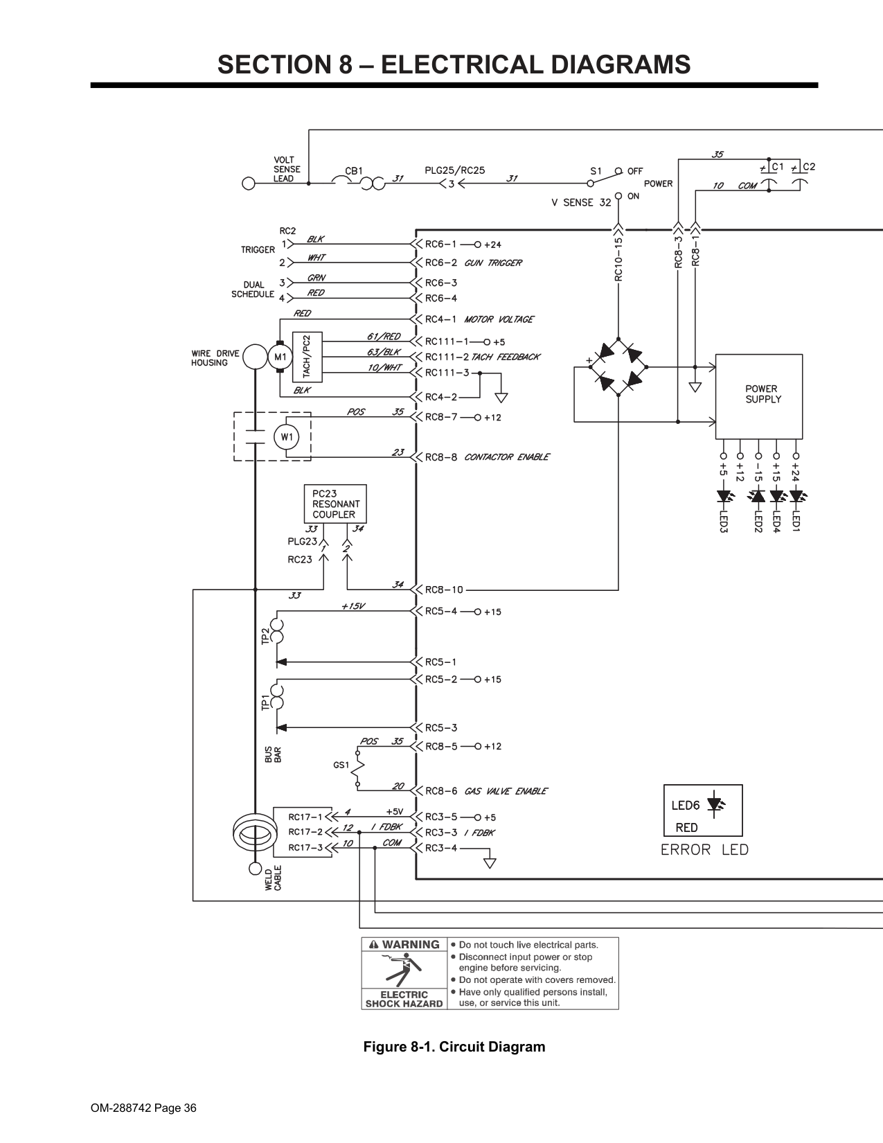
OM-288742 Page 36
Section 8 – Electrical Diagrams
Figure 8-1. Circuit Diagram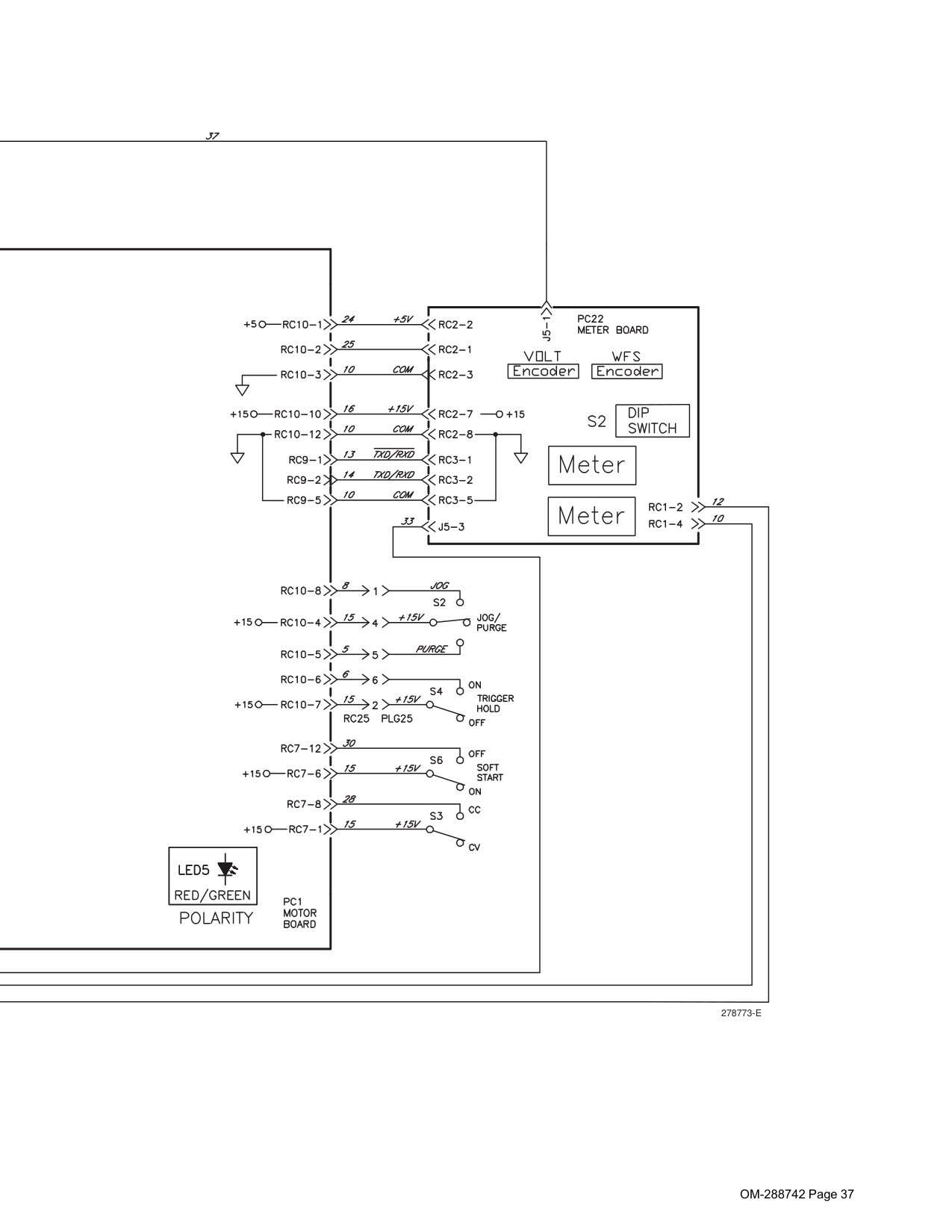
OM-288742 Page 37
278773-E
Effective January 1, 2020 (Equipment with a serial number preface of NA or newer) This limited warranty supersedes all previous Miller warranties and is exclusive with no other guarantees or warranties expressed or implied. LIMITED WARRANTY − Subject to the terms and conditions below, Miller Electric Mfg. LLC, Appleton, Wisconsin, warrants to authorized distributors that new Miller equipment sold after the effective date of this limited warranty is free of defects in material and workmanship at the time it is shipped by Miller. THIS
Warranty Is Expressly In Lieu Of All Other
Warranties, Express Or Implied, Including The
Warranties Of Merchantability And Fitness.
Within the warranty periods listed below, Miller will repair or replace any warranted parts or components that fail due to such defects in material or workmanship. Miller must be notified in writing within thirty (30) days of such defect or failure, at which time Miller will provide instructions on the warranty claim procedures to be followed. Notifications submitted as online warranty claims must provide detailed descriptions of the fault and troubleshooting steps taken to diagnose failed parts. Warranty claims that lack the required information as defined in the Miller Service Operation Guide (SOG) may be denied by Miller. Miller shall honor warranty claims on warranted equipment listed below in the event of a defect within the warranty coverage time periods listed below. Warranty time periods start on the delivery date of the equipment to the end-user purchaser, or 12 months after the equipment is shipped to a North American distributor, or 18 months after the equipment is shipped to an international distributor, whichever occurs first.(Note:
Digital Recorders are Warranted Separately by the Manufacturer.)Miller Products Are Intended For Commercial
And Industrial Users Trained And Experienced In
The Use And Maintenance Of Welding Equipment.
The exclusive remedies for warranty claims are, at Miller’s option, either: (1) repair; or (2) replacement; or, if approved in writing by Miller, (3) the pre-approved cost of repair or replacement at an authorized Miller service station; or (4) payment of or credit for the purchase price (less reasonable depreciation based upon use). Products may not be returned without Miller’s written approval. Return shipment shall be at customer’s risk and expense. The above remedies are F.O.B. Appleton, WI, or Miller’s authorized service facility. Transportation and freight are the customer’s responsibility. TO THE EXTENT PERMITTED BYLaw, The Remedies Herein Are The Sole And
Exclusive Remedies Regardless Of The Legal
Theory. In No Event Shall Miller Be Liable For
Direct,
Indirect,
Special,
Incidental
Or
Consequential Damages (Including Loss Of
Profit) Regardless Of The Legal Theory. Any
Warranty Not Provided Herein And Any Implied
Warranty,
Guaranty,
Or
Representation,
Including
Any
Implied
Warranty
Of
Merchantability Or Fitness For Particular
Purpose, Are Excluded And Disclaimed By
Miller.
Some US states do not allow limiting the duration of an implied warranty or the exclusion of certain damages, so the above limitations may not apply to you. This warranty provides specific legal rights, and other rights may be available depending on your state. In Canada, some provinces provide additional warranties or remedies, and to the extent the law prohibits their waiver, the limitations set out above may not apply. This Limited Warranty provides specific legal rights, and other rights may be available, but may vary by province. Warranty Questions? Call1-800-4-A-Miller
for your local Miller distributor. Your distributor also gives you ... Service You always get the fast, reliable response you need. Most replacement parts can be in your hands in 24 hours. Support Need fast answers to the tough welding questions? Contact your distributor. The expertise of the distributor and Miller is there to help you, every step of the way. mil dom warr 2020-01
Miller Electric Mfg. LLC An Illinois Tool Works Company 1635 West Spencer Street Appleton, WI 54914 USA International Headquarters–USA USA Phone: 920-735-4505 USA & Canada FAX: 920-735-4134 International FAX: 920-735-4125 For International Locations Visit www.MillerWelds.com