
Ask AI
— answers from the official manualAnswers from the official manual.
Common questions
Common Questions
20 totalWhat are the engine specifications for the DB7651-24 snow thrower?
The DB7651-24 is powered by a 212cc Snow Engine with a fuel tank capacity of 0.66 gallons and an engine oil capacity of 16 fl. oz. It features both a 120V electric start and a recoil start system. The clearing width is 24 inches and the clearing height is 21 inches. (Page 3)
How do I clear a clogged chute on the Powersmart Db7651-24?
Stop the engine and wait until all moving parts have come to a complete stop before unclogging. Use the clean-out tool supplied with the machine to remove any obstructions in the chute. After clearing, wipe the tool clean and place it back on top of the auger housing.
What should I do if my Powersmart Db7651-24 won't start?
Ensure that the engine ignition switch is in the ON position, spark plug wire is connected to the spark plug, and the fuel shut-off valve is turned to the ON position. Check for proper maintenance of the spark plug, clean or replace if necessary. Use the Engine Operator's manual or contact customer service for further troubleshooting detailed steps (Page 24).
How do I adjust the drive speed control lever?
Move the speed control lever to any of six positions: four forward speeds and two reverse speeds. Note that there is no neutral setting — disengage the drive control handle for complete stop (Page 18).
How do I set up the skid shoes on my Powersmart Db7651-24?
Locate and remove the pair of skid shoes from your parts bag, loosen and install them loosely using bolts on each side of the auger housing. Set the height above ground to clear snow based on surface conditions: low for smooth surfaces like concrete, higher for gravel or rough terrain (Page 14).
What should I do if my Powersmart Db7651-24 keeps stopping and restarting?
Check the causes listed in the troubleshooting guide such as fuel system issues or incorrect spark plug settings. Clean carburetor, use fresh gasoline, check spark plug gap and condition, inspect drive belts for tightness (Page 24).
Show 14 more questions
How do I replace a broken shear pin in the auger?
How do I prepare my Powersmart Db7651-24 for winter storage?
What do I need to know about tire maintenance for my Powersmart Db7651-24?
How do I engage the auger control handle on my Powersmart Db7651-24?
What should I do if my Powersmart Db7651-24 discharges snow backwards?
How do I safely handle gasoline when refueling the snow thrower?
How do I properly start the auger and drive on the snow thrower?
What should I do if the snow discharge chute becomes clogged?
How do I replace broken shear pins on the auger?
What is the correct tire pressure for the DB7651-24?
What are the drive speed settings available on this snow thrower?
Why won't my engine start, and how do I troubleshoot it?
How should I store the snow thrower at the end of the season?
What is the warranty coverage for the PowerSmart DB7651-24?
Full Manual
32 pages

Instruction Manual
24 inch Two Stage Gas Snow Thrower Model # DB7651-24Have product questions or need technical support? Please feel free to contact us!
Website: www.Amerisuninc.com
Toll free: 1-800-791-9458 Mon-Fri 9-5 EST
Email: [email protected]
3
Contents
Technical data…...………………………………………………………... 3 Introduction………………………………………………………………. 4 Safety information…….………………………………………………... 4 Knowing your snow thrower…………………………………………… 10 Assembly and adjustments……………………………………………... 13 Snow thrower preparation…....………………………………………… 15 Operating your snow thrower...…………………………………………. 18 Maintenance……………………………………………………………... 19 Storage & Cleaning…………...…………………………………………. 23 Troubleshooting…………………………………………………………. 24 Exploded view and parts list……………………………………………... 27 Two (2) years limited warranty……………………...…………………… 33Technical Data
24 inch Two Stage Electric Start Snow Thrower
Model #:
Db7651-24
Engine:212cc Snow Engine Engine oil Capacity:
16 fl.oz Fuel Tank Capacity:
0.66 Gallon Start System:
120V Electric / Recoil Clearing Width:
24 in Clearing Height:
21 in Chute Rotation Angle:
180º Speed:
4 Forward, 2 Reverse Tire Size:
13 in Overall Dimensions (L x W x H): 55 x 24 x 36.5 in Weight:
180 lbs Thank you for purchasing Power Smart products. Please register online at www. Amerisuninc.com. The information will allow us to track your warranty and update on your unit.
Important: Our company does not provide email or personal information to any third party for any reason. For any questions check our website or call customer service at (800)791 9458.
4
Introduction
Thank You for Purchasing a PowerSmart® Product. This manual provides information regarding the safe operation and maintenance of this product. Every effort has been made to ensure the accuracy of the information in this manual. PowerSmart® reserves the right to change this product and specifications at any time without prior notice. Please keep this manual available to all users during the entire life of the generator. This manual contains special messages to bring attention to potential safety concerns, generator damage as well as helpful operating and servicing information. Please read all the information carefully to avoid injury and machine damage.Questions? Problems?
In order to answer questions and solve problems in the most efficient and speedy manner, contact Customer Service at (800) 791-9458, Mon-Fri 9am-5pm EST or email: [email protected].Notice Regarding Emissions
Engines that are certified to comply with U.S. EPA emission regulations for SORE (Small Off Road Equipment), are certified to operate on regular unleaded gasoline, and may include the following emission control systems: (EM) Engine Modifications and (TWC) Three-Way Catalyst (if so equipped).Safety Information
This symbol points out important safety instructions which, if not followed, could endanger the personal safety and or property of yourself and others. Read and follow all instructions in this manual before attempting to operate this machine. Failure to comply with these instructions may result in personal injury.
WARNING! This machine was built to be operated according to the safe operation practices in this manual. As with any type of power equipment, carelessness or error on the part of the operator can result in serious injury. This machine is capable of amputating fingers, hands, toes and feet and throwing foreign objects. Failure to observe the following safety instructions could result in serious injury or death.
It is your responsibility to restrict the use of this power machine to persons who read, understand and follow the warnings and instructions in this manual and on the machine.
ROTATING PARTS! Only use clean-out tool to clear blockages. NEVER use your hands.
NEVER direct discharge towards persons or property that may be injured or damaged by thrown objects.
Keep people away from unit while operating. Keep children out of work area and under watchful care of a responsible adult.
5
Training
Read, understand, and follow all instructions on the machine and in the manual(s) before attempting to assemble and operate. Keep this manual in a safe place for future and regular reference.
• Be familiar with all controls and their proper operation. Know how to stop the machine and disengage them quickly.
• Never allow children under 14 years of age to operate this machine. Children 14 and over should read and understand the instructions and safe operation practices in this manual and on the machine and be trained and supervised by an adult.
• Never allow adults to operate this machine without proper instruction.
• Thrown objects can cause serious personal injury. Plan your snow-throwing pattern to avoid discharge of material toward roads, bystanders and the like.
• Keep bystanders, pets and children at least 75 feet from the machine while it is in operation. Stop machine if anyone enters the area.
• Exercise caution to avoid slipping or falling, especially when operating in reverse.
Preparation
Thoroughly inspect the area where the equipment is to be used. Remove all doormats, newspapers, sleds, boards, wires, branches and other foreign object, which could be tripped over or thrown by the auger /impeller.
• Always wear safety glasses or eye shields during operation and while performing an adjustment or repair to protect your eyes, thrown objects which ricochet can cause serious injury to the eyes.
• Do not operate without wearing adequate winter outer garments. Do not wear jewelry, long scarves or other loose clothing, which could become entangled in moving parts, wear footwear which will improve footing on slippery surfaces.
• Use a grounded three-wire extension cord and receptacle for all machines with electric start engines.
• Adjust housing height to clear gravel or crushed rock surfaces.
• Disengage all control levers before starting the engine.
• Never attempt to make any adjustments while engine is running, except where specifically recommended in the operator's manual.
• Let engine and machine adjust to outdoor temperature before starting to clear snow.
Personal Safety
• Engine exhaust, and certain vehicle components contain or emit chemicals known to cause cancer, birth defects or other reproductive harm.
6 • Read, understand and follow all instructions on your Snow Thrower and in this Operator's Manual before attempting to assemble and operate your machine.
• Keep this manual in a safe place for future and regular reference. If replacement parts are needed, refer to the manual.
• Stay alert, watch what you are doing and use common sense when operating your Snow Thrower.
• Do not use your Snow Thrower while you are tired or under the influence of drugs, alcohol, medication. A moment of inattention while operating the Snow Thrower may result in severe bodily injury.
• NEVER LEAVE YOUR RUNNING SNOW THROWER UNATTENDED. Stop the engine.
• Do leave your Snow Thrower until it has come to a complete stop.
• When stepping backwards, be cautious about any obstacles beneath your feet or behind you avoid falling.
Service
• Stop the engine before making any adjustments. Check for misalignment, breakage of or binding of moving parts, and any other conditions that may affect operation.
• If damaged, have the Snow Thrower serviced by a qualified repair person using only identical replacement parts. This will ensure that the safety of the Snow Thrower is maintained.
Safe Handling Of Gasoline
To avoid personal injury or property damage use extreme care in handling gasoline. Gasoline is extremely flammable and the vapors are explosive. Serious personal injury can occur when gasoline is spilled on yourself or your clothes which can ignite, wash your skin and change clothes immediately.
• Use only an approved gasoline container.
• Extinguish all cigarettes, cigars, pipes and other sources of ignition.
• Never fuel machine indoors.
• Never remove gas cap or add fuel while the engine is hot or running.
• Allow engine to cool at least two minutes before refueling.
• Never over fill fuel tank.
• Replace gasoline cap and tighten securely.
• If gasoline is spilled, wipe it off the engine and equipment. Move machine to another area. Wait 5 minutes before starting the engine.
7 • Never store the machine or fuel container inside where there is an open flame, spark or pilot light (e.g. furnace, water heats, space heater, clothes dryer etc.).
• Allow machine to cool at least 5 minutes before storing.
• Never fill containers inside a vehicle or on a truck or trailer bed with a plastic liner. Always place containers on the ground away from your vehicle before filling.
• If possible, remove gas-powered equipment from the truck or trailer and refuel it on the ground.
• If this is not possible, then refuel such equipment on a trailer with a portable container, rather than from a gasoline dispenser nozzle.
• Keep the nozzle in contact with the rim of the fuel tank or container opening at all times until fueling is complete. Do not use a nozzle lock open device.
Operation
• Do not put hands or feet near rotating parts, in the auger impeller housing or chute assembly. Contact with the rotating parts can amputate hands and feet.
• The auger impeller control lever is a safety device. Never bypass its operation. Doing so makes the machine unsafe and may cause personal injury.
• The control levers must operate easily in both directions and automatically return to the disengaged position when released.
• Never operate with a missing or damaged chute assembly. Keep all safety devices in place and working.
• Never run an engine indoors or in a poorly ventilated area. Engine exhaust contains carbon monoxide, an odorless and deadly gas.
• Do not operate machine while under the influence of alcohol or drugs.
• Muffler and engine become hot and can cause a bum. Do not touch. Keep children away.
• Exercise extreme caution when operating on or crossing gravel surfaces. Stay alert for hidden hazards or traffic.
• Exercise caution when changing direction and while operating on slopes.
• Plan your snow-throwing pattern to avoid discharge towards windows, walls, cars etc. Thus, avoiding possible property damage or personal injury caused by a ricochet.
• Never direct discharge at children, bystanders and pets or allow anyone in front of the machine.
• Do not overload machine capacity by attempting to clear snow at too fast of a rate.
• Never operate this machine without good visibility or light. Always be sure of your footing and keep a firm hold on the handles. Walk, never run.
8
• Disengage power to the auger impeller when transporting or not in use.
• Never operate machine at high transport speeds on slippery surfaces. Look down and behind and use care when backing up.
• If the machine should start to vibrate abnormally, stop the engine, disconnect the spark plug wire and ground it against the engine. Inspect thoroughly for damage. Repair any damage before starting and operating.
• Disengage all control levers and stop engine before you leave the operating (behind the handles).
• Wait until the auger /impeller comes to a complete stop before unclogging the chute assembly, making any adjustments, or inspections.
• Never put your hand in the discharge or collector openings. Always use the clean-out tool provided to unclog the discharge opening. Do not unclog chute assembly while engine is running. Shut off engine and remain behind handles until all moving parts have stopped before unclogging.
• Use only attachments and accessories approved by the manufacturer (e.g. wheel weights, tire chains, cabs etc.).
• When staring engine, pull cord slowly until resistance is felt, then pull rapidly, Rapid retraction of starter cord (kickback) will pull hand and arm toward engine faster then you can let go. Broken bones, fractures, bruises or sprains could result.
• If situations occur which are not covered in this manual, use care and good judgment contact customer support for assistance.
Maintenance & Storage
• Never tamper with safety devices. Check their proper operation regularly. Refer to the maintenance and adjustment sections of manual.
• Before cleaning, repairing, or inspecting machine disengage all control levers and stop the engine.
• Wait until the auger impeller comes to a complete stop. Disconnect the spark plug wire to prevent unintended starting.
• Check bolts and screws for proper tightness at frequent intervals to keep the machine in safe working condition. Also, visually inspect machine for any damage.
• Do not change the engine governor setting or overspeed the engine. The governor controls the maximum safe operating speed of the engine.
• Snow thrower shave plates and skid shoes are subject to wear and damage. For your safety protection, frequently check all components and replace with original equipment manufacturers (OEM) parts only. Use of parts which do not meet the original equipment specifications may lead to improper performance and compromise safety.
9 • Check control levels periodically to verify they engage and disengage properly and adjust, if necessary. Refer to the adjustment section in this operator's manual for instructions.
• Maintain or replace safety and instruction labels, as necessary.
• Observe proper disposal laws and regulations for gas, oil, etc. to protect the environment.
• Prior to storing, run machine a few minutes to clear snow from machine and prevent freeze up of auger impeller.
• Never store the machine or fuel container inside where there is an open flame, spark or pilot light such as water heater, furnace, clothes dryer etc.
• Always refer to the operator's manual for proper instructions on off-season storage.
• Check fuel line, tank, cap and fittings frequently for cracks or leaks. Replace if necessary.
• Do not crank engine with spark plug removed.
• Have the machine inspected annually by an authorized service dealer to ensure that all mechanical and safety systems are working properly and do not worn excessively. Failure to do so can result in accidents, injuries or death
Do Not Modify The Engine
To avoid serious injury or death, do not modify engine in any way. Tampering with the governor setting can lead to a runaway engine and cause it to operate at unsafe speeds. Never tamper with factory setting of engine governor.
10
Knowing Your Snow Thrower
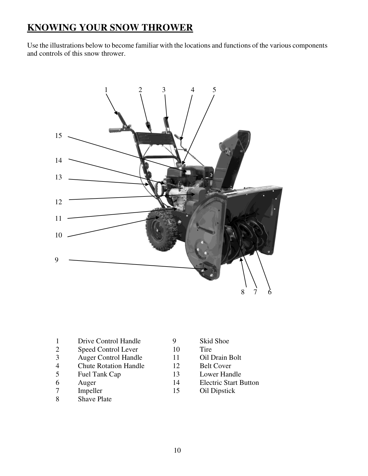
Use the illustrations below to become familiar with the locations and functions of the various components and controls of this snow thrower.
1
Drive Control Handle
9
Skid Shoe 2
Speed Control Lever
10
Tire 3
Auger Control Handle
11
Oil Drain Bolt 4
Chute Rotation Handle
12
Belt Cover 5
Fuel Tank Cap
13
Lower Handle 6
Auger
14
Electric Start Button 7
Impeller
15
Oil Dipstick 8
Shave Plate
1 2 3 4 5
15
14
13
12
11
10
9 8 7 6
11
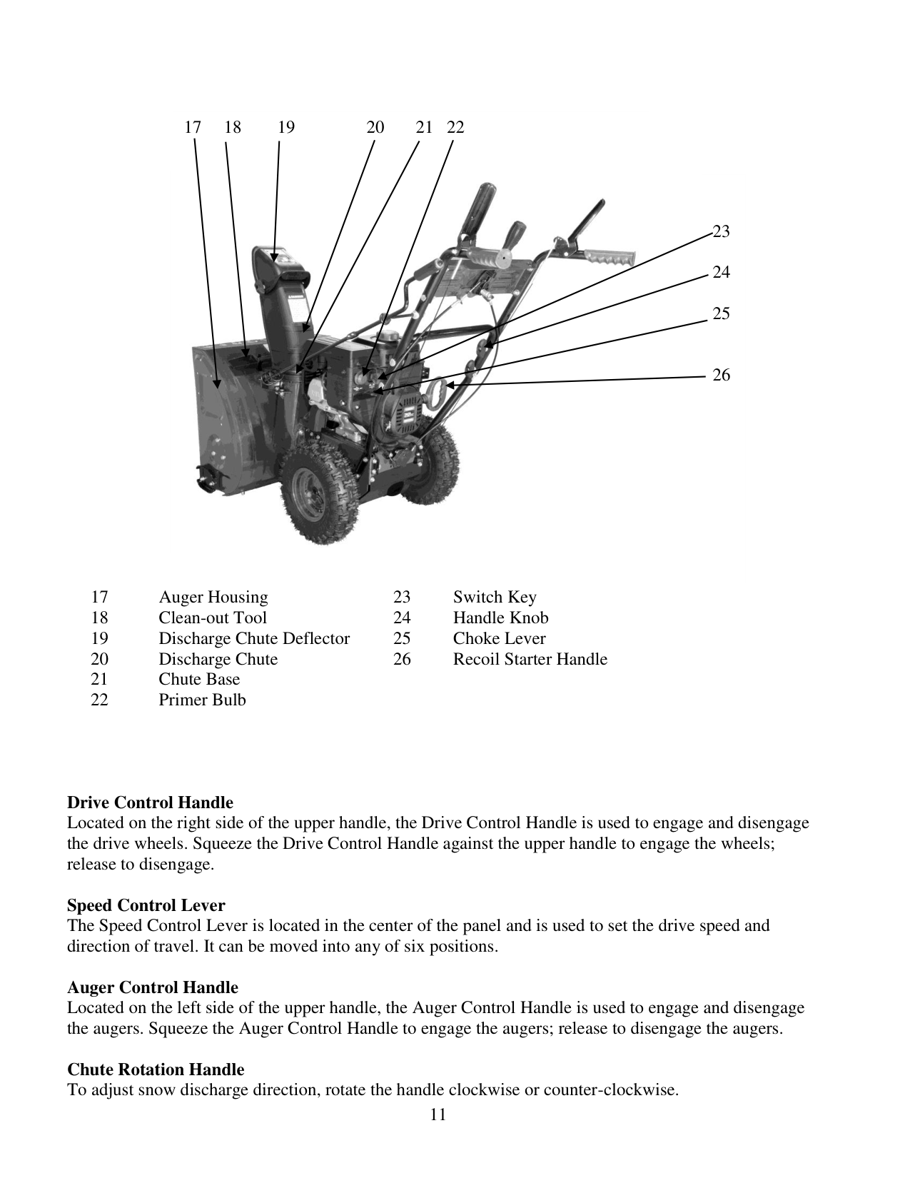
17
Auger Housing
23
Switch Key 18
Clean-out Tool
24
Handle Knob 19
Discharge Chute Deflector
25
Choke Lever 20
Discharge Chute
26
Recoil Starter Handle 21
Chute Base
22
Primer Bulb
Drive Control Handle Located on the right side of the upper handle, the Drive Control Handle is used to engage and disengage the drive wheels. Squeeze the Drive Control Handle against the upper handle to engage the wheels; release to disengage.
Speed Control Lever The Speed Control Lever is located in the center of the panel and is used to set the drive speed and direction of travel. It can be moved into any of six positions.
Auger Control Handle Located on the left side of the upper handle, the Auger Control Handle is used to engage and disengage the augers. Squeeze the Auger Control Handle to engage the augers; release to disengage the augers.
Chute Rotation Handle To adjust snow discharge direction, rotate the handle clockwise or counter-clockwise. 17 18 19 20 21 22
23
24
25
26
12
Skid Shoe Position the shoes based on the surface conditions. Adjust upward for hard-packed snow. Adjust downward when operating on gravel or crushed rock surfaces. Augers and Impeller When engaged, the augers rotate to cut snow and direct it into the impeller housing to be discharged out the chute.
Clean-out Tool The chute Clean-out Tool is conveniently fastened to the rear of the auger housing with a mounting clip. It is used to clean the chute assembly and chute opening when snow and ice become lodged. WARNING! Never use your hands to clear a clogged chute assembly. Shut off engine and remain behind handles until all moving parts have stopped before unclogging.
Discharge Chute The chute provides a discharge path for snow being thrown. The chute is adjustable.
Shave Plate The Shave Plate maintains contact with pavement as the snow thrower is propelled, allowing snow close to pavement's surface to be discharged.
13
Assembly And Adjustments
The following section describes steps necessary to prepare the snow thrower for use. If after reading this section, you are unsure about how to perform any of the steps please call (800) 791-9458 Mon-Fri 9-5 EST for customer service. Failure to perform these steps properly can damage the snow thrower or shorten its life.
Unpacking
Unpack the snow thrower and all its parts, and compare against the list below.
Assembly
Your Snow Thrower will require some assembly. Please complete the following steps before using your Snow Thrower.
WARNING: This snow thrower is heavy. Assembly procedures may require lifting equipment or two people.
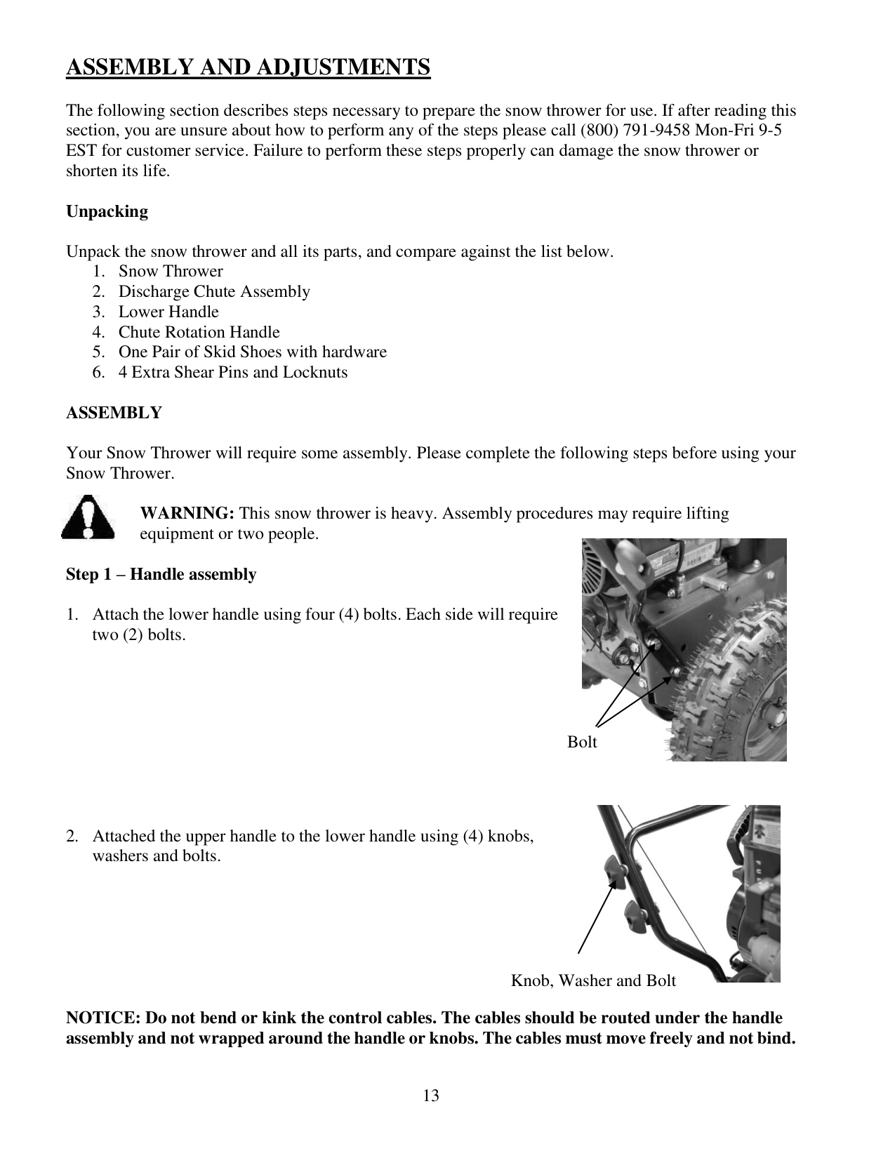
Step 1 – Handle assembly
NOTICE: Do not bend or kink the control cables. The cables should be routed under the handle assembly and not wrapped around the handle or knobs. The cables must move freely and not bind.
Bolt Knob, Washer and Bolt
14
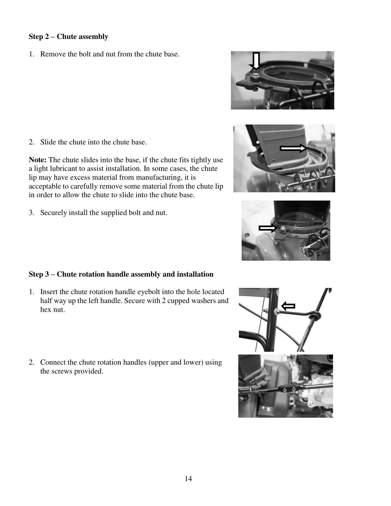
Step 2 – Chute assembly
Note: The chute slides into the base, if the chute fits tightly use a light lubricant to assist installation. In some cases, the chute lip may have excess material from manufacturing, it is acceptable to carefully remove some material from the chute lip in order to allow the chute to slide into the chute base.
Step 3 – Chute rotation handle assembly and installation
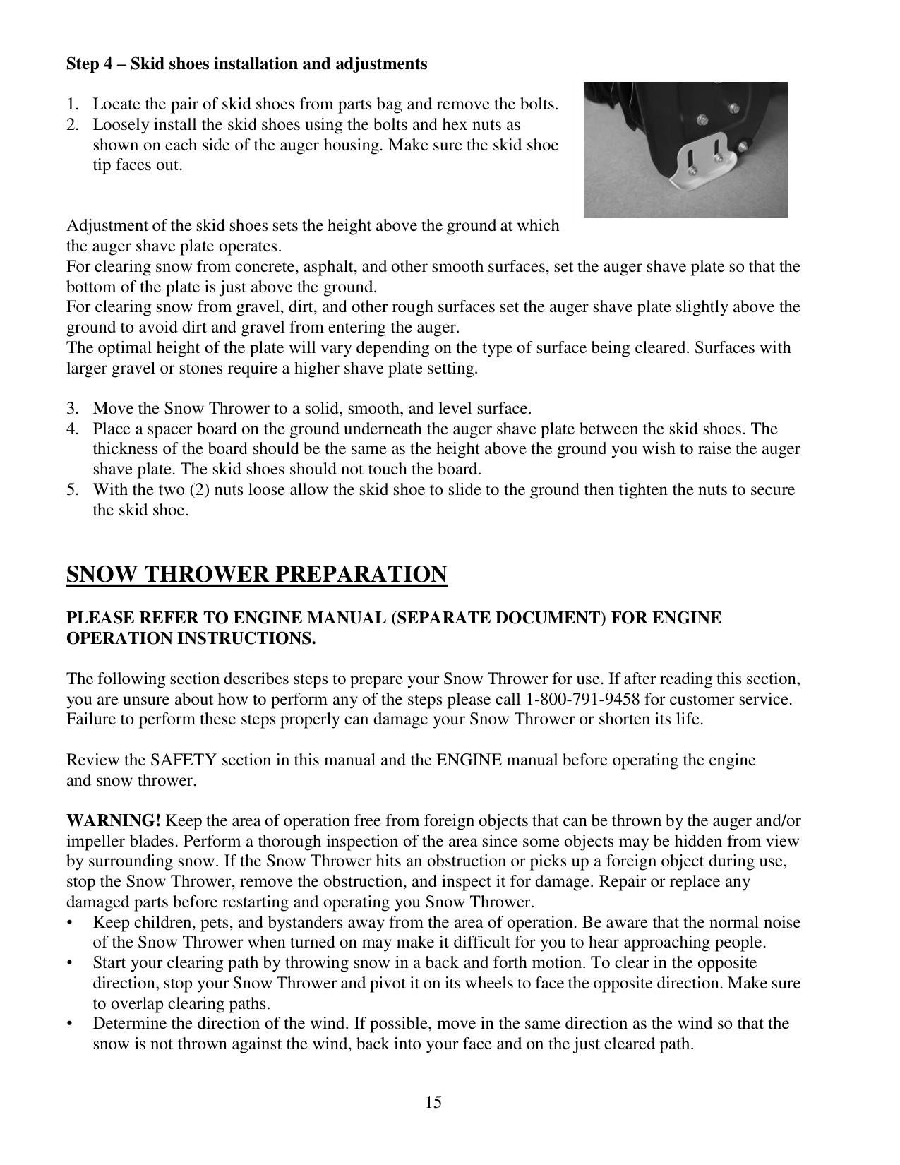
15 Step 4 – Skid shoes installation and adjustments
Adjustment of the skid shoes sets the height above the ground at which the auger shave plate operates. For clearing snow from concrete, asphalt, and other smooth surfaces, set the auger shave plate so that the bottom of the plate is just above the ground. For clearing snow from gravel, dirt, and other rough surfaces set the auger shave plate slightly above the ground to avoid dirt and gravel from entering the auger. The optimal height of the plate will vary depending on the type of surface being cleared. Surfaces with larger gravel or stones require a higher shave plate setting.
Snow Thrower Preparation
Please Refer To Engine Manual (Separate Document) For Engine
Operation Instructions.
The following section describes steps to prepare your Snow Thrower for use. If after reading this section, you are unsure about how to perform any of the steps please call 1-800-791-9458 for customer service. Failure to perform these steps properly can damage your Snow Thrower or shorten its life.
Review the SAFETY section in this manual and the ENGINE manual before operating the engine and snow thrower.
WARNING! Keep the area of operation free from foreign objects that can be thrown by the auger and/or impeller blades. Perform a thorough inspection of the area since some objects may be hidden from view by surrounding snow. If the Snow Thrower hits an obstruction or picks up a foreign object during use, stop the Snow Thrower, remove the obstruction, and inspect it for damage. Repair or replace any damaged parts before restarting and operating you Snow Thrower. • Keep children, pets, and bystanders away from the area of operation. Be aware that the normal noise of the Snow Thrower when turned on may make it difficult for you to hear approaching people. • Start your clearing path by throwing snow in a back and forth motion. To clear in the opposite direction, stop your Snow Thrower and pivot it on its wheels to face the opposite direction. Make sure to overlap clearing paths. • Determine the direction of the wind. If possible, move in the same direction as the wind so that the snow is not thrown against the wind, back into your face and on the just cleared path.
16 WARNING! DO NOT USE YOUR HANDS TO UNCLOG CHUTE. Stop the motor before removing debris. Use the supplied clean out tool to unclog the chute. Do not walk in front of your running Snow Thrower. Do not direct discharged snow towards bystanders. • Do not apply additional man-made load to the engine since this may damage the engine. • Some parts of your Snow Thrower may freeze under extreme temperature conditions. Do not attempt to operate your Snow Thrower with frozen parts. If the parts freeze while your Snow Thrower is in use, stop your Snow Thrower and inspect it for frozen parts. Thaw all parts before restarting and operating your Snow Thrower. Never force parts or controls that have frozen. Never use an open flame of any sort to thaw frozen parts.
Pre-Operation Inspection - IMPORTANT!!! Before using your Snow Thrower for the first time, check the following: • Have you read and followed all setup and operation procedures for the engine as outlined in the ENGINE manual? • Has the engine been filled with oil and gasoline to the proper level? • Are all snow thrower components properly attached and assembled? • Are there any broken or damaged parts? • Are all fasteners tight? • Are the tires inflated to the proper pressure?
NOTICE: If you are unsure about the assembly or condition of any of your Snow Thrower parts, please call our customer service department at (800)791 9458.
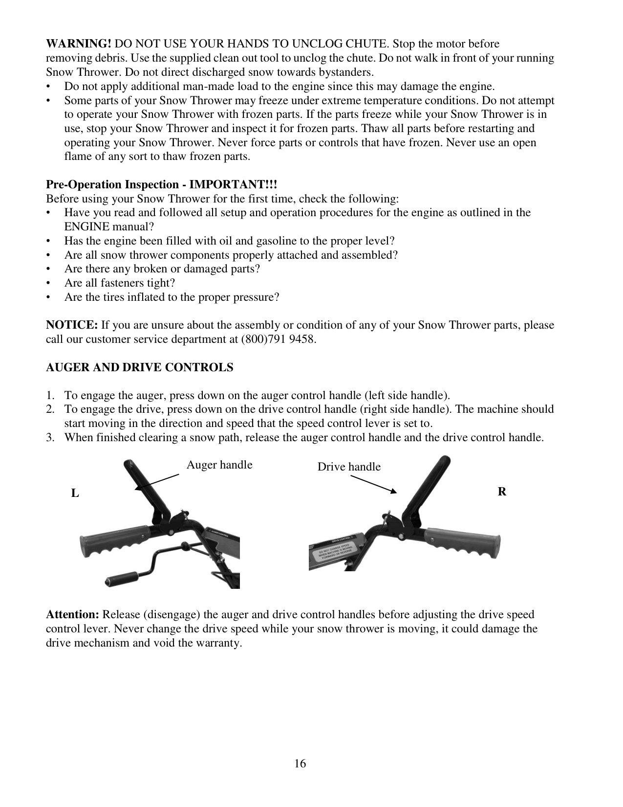
Auger And Drive Controls
Attention: Release (disengage) the auger and drive control handles before adjusting the drive speed control lever. Never change the drive speed while your snow thrower is moving, it could damage the drive mechanism and void the warranty.
Auger handle Drive handle
L
R
17
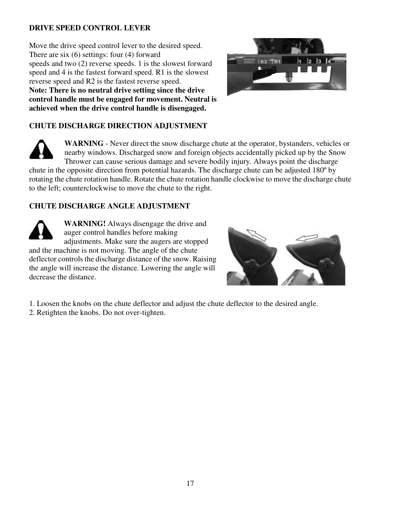
Drive Speed Control Lever
Move the drive speed control lever to the desired speed. There are six (6) settings: four (4) forward speeds and two (2) reverse speeds. 1 is the slowest forward speed and 4 is the fastest forward speed. R1 is the slowest reverse speed and R2 is the fastest reverse speed. Note: There is no neutral drive setting since the drive control handle must be engaged for movement. Neutral is achieved when the drive control handle is disengaged.
Chute Discharge Direction Adjustment
WARNING - Never direct the snow discharge chute at the operator, bystanders, vehicles or nearby windows. Discharged snow and foreign objects accidentally picked up by the Snow Thrower can cause serious damage and severe bodily injury. Always point the discharge chute in the opposite direction from potential hazards. The discharge chute can be adjusted 180º by rotating the chute rotation handle. Rotate the chute rotation handle clockwise to move the discharge chute to the left; counterclockwise to move the chute to the right.
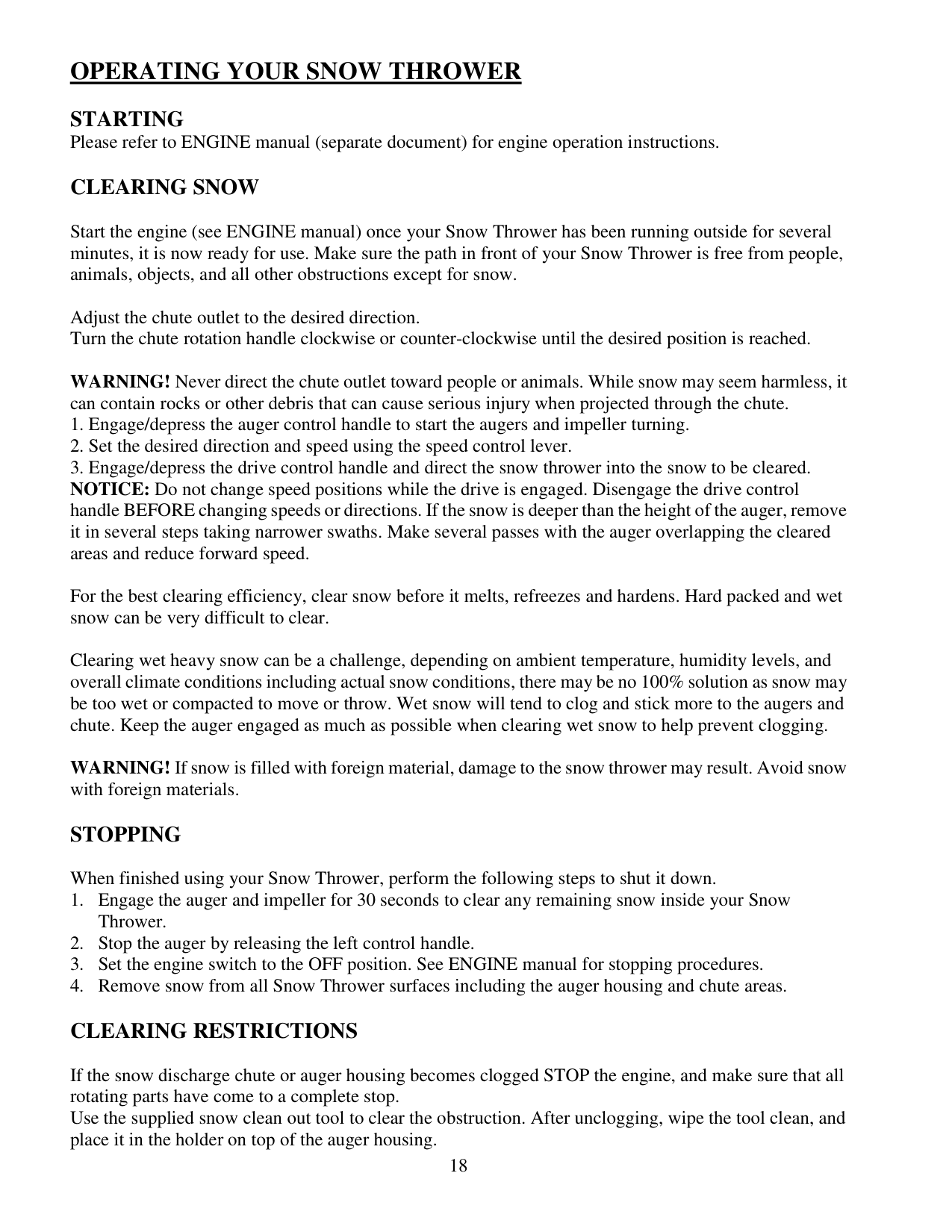
Chute Discharge Angle Adjustment
WARNING! Always disengage the drive and auger control handles before making adjustments. Make sure the augers are stopped and the machine is not moving. The angle of the chute deflector controls the discharge distance of the snow. Raising the angle will increase the distance. Lowering the angle will decrease the distance.
18
Operating Your Snow Thrower
Starting
Please refer to ENGINE manual (separate document) for engine operation instructions.Clearing Snow
Start the engine (see ENGINE manual) once your Snow Thrower has been running outside for several minutes, it is now ready for use. Make sure the path in front of your Snow Thrower is free from people, animals, objects, and all other obstructions except for snow.
Adjust the chute outlet to the desired direction. Turn the chute rotation handle clockwise or counter-clockwise until the desired position is reached.
WARNING! Never direct the chute outlet toward people or animals. While snow may seem harmless, it can contain rocks or other debris that can cause serious injury when projected through the chute.
For the best clearing efficiency, clear snow before it melts, refreezes and hardens. Hard packed and wet snow can be very difficult to clear.
Clearing wet heavy snow can be a challenge, depending on ambient temperature, humidity levels, and overall climate conditions including actual snow conditions, there may be no 100% solution as snow may be too wet or compacted to move or throw. Wet snow will tend to clog and stick more to the augers and chute. Keep the auger engaged as much as possible when clearing wet snow to help prevent clogging.
WARNING! If snow is filled with foreign material, damage to the snow thrower may result. Avoid snow with foreign materials.
Stopping
When finished using your Snow Thrower, perform the following steps to shut it down.
Clearing Restrictions
If the snow discharge chute or auger housing becomes clogged STOP the engine, and make sure that all rotating parts have come to a complete stop. Use the supplied snow clean out tool to clear the obstruction. After unclogging, wipe the tool clean, and place it in the holder on top of the auger housing.
19
Maintenance
WARNING! Never perform maintenance while your Snow Thrower is running. Turn OFF the engine before performing any maintenance tasks on your Snow Thrower.
Proper maintenance of your Snow Thrower will help prolong its life. Please perform the following maintenance procedures as required.
Please read the ENGINE manual for engine maintenance procedures.
Do not attempt to repair your Snow Thrower unless you have the proper tools and instructions for disassembly and repair.
Check the bolts at frequent intervals for proper tightness to ensure that the equipment is in safe working condition.
After each snow removal session, run the Snow Thrower for a few minutes to prevent the collector /impeller from freezing. Stop the engine, wait for all revolving parts to stop completely, and wipe residual ice and snow off the unit. Rotate the chute rotation handle several times to remove any excess snow.
Maintenance Procedures
Tire Inflation
Before each use of your Snow Thrower, check the tire pressure. The pressure in each tire should be in the range of 20-24 psi for the best performance. The pressure can be checked using an ordinary tire pressure gauge. Fill the tires using a small or pressure regulated air compressor.
WARNING! DO NOT OVER-INFLATE THE TIRES. Over-inflating could cause a tire to burst and cause severe bodily injury.
Shave Plate Replacement
Remove both skid shoes and hardware including carriage bolts and nuts which attach shave plate to snow thrower housing. Reassemble new shave plate, making sure heads of the carriage bolts are to the inside of the auger housing.
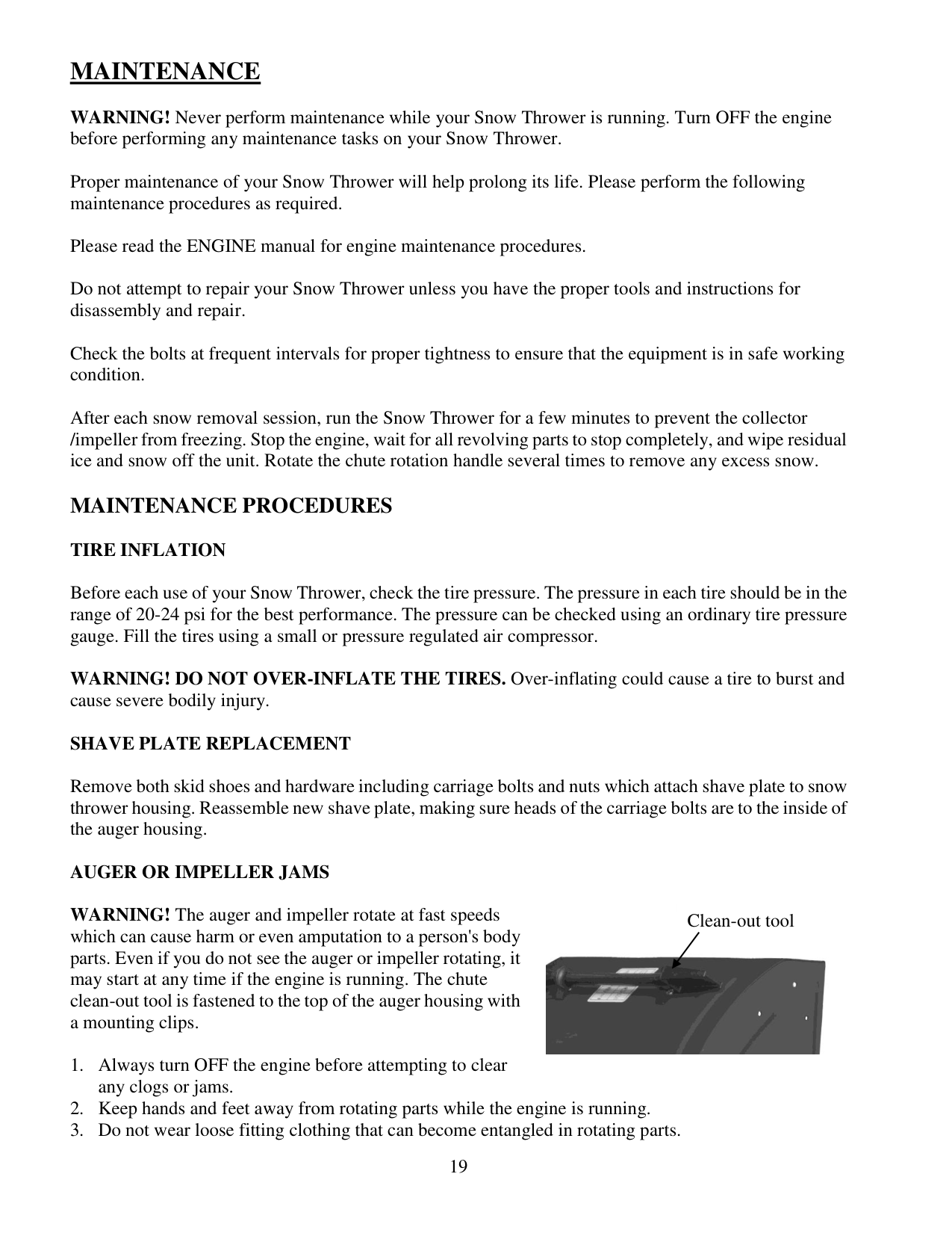
Auger Or Impeller Jams
WARNING! The auger and impeller rotate at fast speeds which can cause harm or even amputation to a person's body parts. Even if you do not see the auger or impeller rotating, it may start at any time if the engine is running. The chute clean-out tool is fastened to the top of the auger housing with a mounting clips.
20
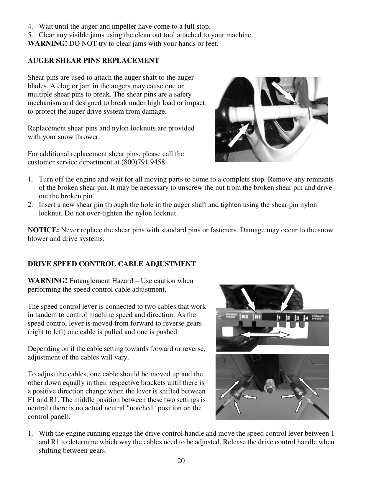
Auger Shear Pins Replacement
Shear pins are used to attach the auger shaft to the auger blades. A clog or jam in the augers may cause one or multiple shear pins to break. The shear pins are a safety mechanism and designed to break under high load or impact to protect the auger drive system from damage.
Replacement shear pins and nylon locknuts are provided with your snow thrower.
For additional replacement shear pins, please call the customer service department at (800)791 9458.
NOTICE: Never replace the shear pins with standard pins or fasteners. Damage may occur to the snow blower and drive systems.
Drive Speed Control Cable Adjustment
WARNING! Entanglement Hazard – Use caution when performing the speed control cable adjustment.
The speed control lever is connected to two cables that work in tandem to control machine speed and direction. As the speed control lever is moved from forward to reverse gears (right to left) one cable is pulled and one is pushed.
Depending on if the cable setting towards forward or reverse, adjustment of the cables will vary.
To adjust the cables, one cable should be moved up and the other down equally in their respective brackets until there is a positive direction change when the lever is shifted between F1 and R1. The middle position between these two settings is neutral (there is no actual neutral "notched" position on the control panel).
21
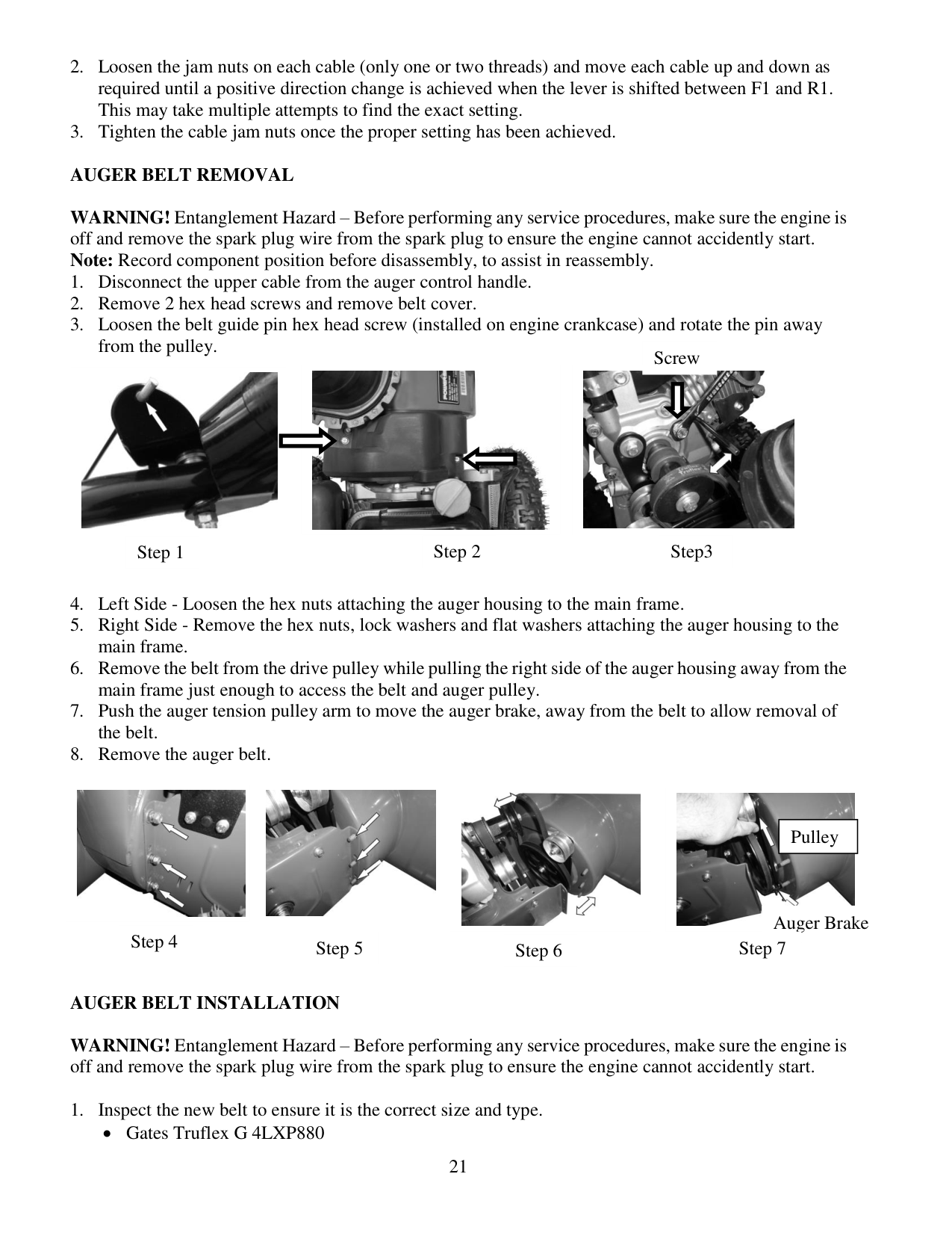
Auger Belt Removal
WARNING! Entanglement Hazard – Before performing any service procedures, make sure the engine is off and remove the spark plug wire from the spark plug to ensure the engine cannot accidently start. Note: Record component position before disassembly, to assist in reassembly.
Auger Belt Installation
WARNING! Entanglement Hazard – Before performing any service procedures, make sure the engine is off and remove the spark plug wire from the spark plug to ensure the engine cannot accidently start.
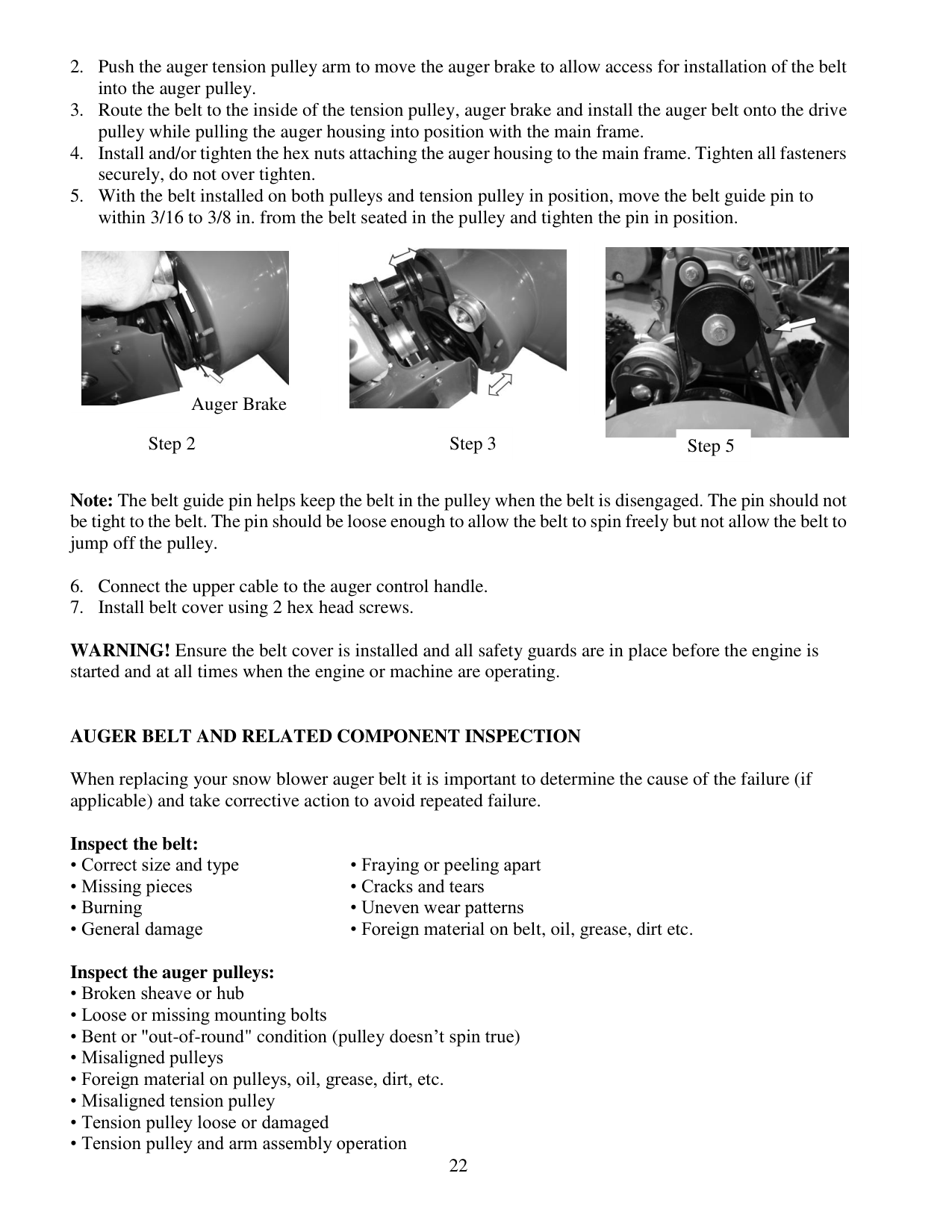
Step 1 Step 2 Step3 Auger Brake Step 4 Step 5 Step 6 Step 7 Screw Pulley
22
Note: The belt guide pin helps keep the belt in the pulley when the belt is disengaged. The pin should not be tight to the belt. The pin should be loose enough to allow the belt to spin freely but not allow the belt to jump off the pulley.
WARNING! Ensure the belt cover is installed and all safety guards are in place before the engine is started and at all times when the engine or machine are operating.
Auger Belt And Related Component Inspection
When replacing your snow blower auger belt it is important to determine the cause of the failure (if applicable) and take corrective action to avoid repeated failure.
Inspect the belt:
Inspect the auger pulleys:
Step 2 Auger Brake Step 3 Step 5
23
Inspect the auger engagement handle and cable:
Storage & Cleaning
Proper Storage Procedures
WARNING! Never store your Snow Thrower for extended periods of time with fuel in the tank or carburetor. Fuel stabilizer can be added to the fuel in can to extend its shelf life for storage.
Store the unit in a locked, dry place out of the reach of children to prevent unauthorized use or damage. Cover loosely with a tarp for added protection.
Cleaning
Note: Do not clean with water. Water will freeze due to low temperature and damage the machine.
24
Troubleshooting
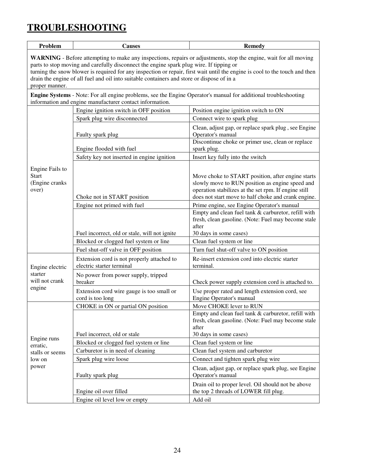
Problem Causes Remedy WARNING - Before attempting to make any inspections, repairs or adjustments, stop the engine, wait for all moving parts to stop moving and carefully disconnect the engine spark plug wire. If tipping or turning the snow blower is required for any inspection or repair, first wait until the engine is cool to the touch and then drain the engine of all fuel and oil into suitable containers and store or dispose of in a proper manner. Engine Systems - Note: For all engine problems, see the Engine Operator's manual for additional troubleshooting information and engine manufacturer contact information. Engine Fails to Start (Engine cranks over) Engine ignition switch in OFF position Position engine ignition switch to ON Spark plug wire disconnected Connect wire to spark plug Faulty spark plug Clean, adjust gap, or replace spark plug , see Engine Operator's manual Engine flooded with fuel Discontinue choke or primer use, clean or replace spark plug. Safety key not inserted in engine ignition Insert key fully into the switch Choke not in START position Move choke to START position, after engine starts slowly move to RUN position as engine speed and operation stabilizes at the set rpm. If engine still does not start move to half choke and crank engine. Engine not primed with fuel Prime engine, see Engine Operator's manual Fuel incorrect, old or stale, will not ignite Empty and clean fuel tank & carburetor, refill with fresh, clean gasoline. (Note: Fuel may become stale after 30 days in some cases) Blocked or clogged fuel system or line Clean fuel system or line Fuel shut-off valve in OFF position Turn fuel shut-off valve to ON position Engine electric starter will not crank engine Extension cord is not properly attached to electric starter terminal Re-insert extension cord into electric starter terminal. No power from power supply, tripped breaker Check power supply extension cord is attached to. Extension cord wire gauge is too small or cord is too long Use proper rated and length extension cord, see Engine Operator's manual Engine runs erratic, stalls or seems low on power CHOKE in ON or partial ON position Move CHOKE lever to RUN Fuel incorrect, old or stale Empty and clean fuel tank & carburetor, refill with fresh, clean gasoline. (Note: Fuel may become stale after 30 days in some cases) Blocked or clogged fuel system or line Clean fuel system or line Carburetor is in need of cleaning Clean fuel system and carburetor Spark plug wire loose Connect and tighten spark plug wire Faulty spark plug Clean, adjust gap, or replace spark plug, see Engine Operator's manual Engine oil over filled Drain oil to proper level. Oil should not be above the top 2 threads of LOWER fill plug. Engine oil level low or empty Add oil
25
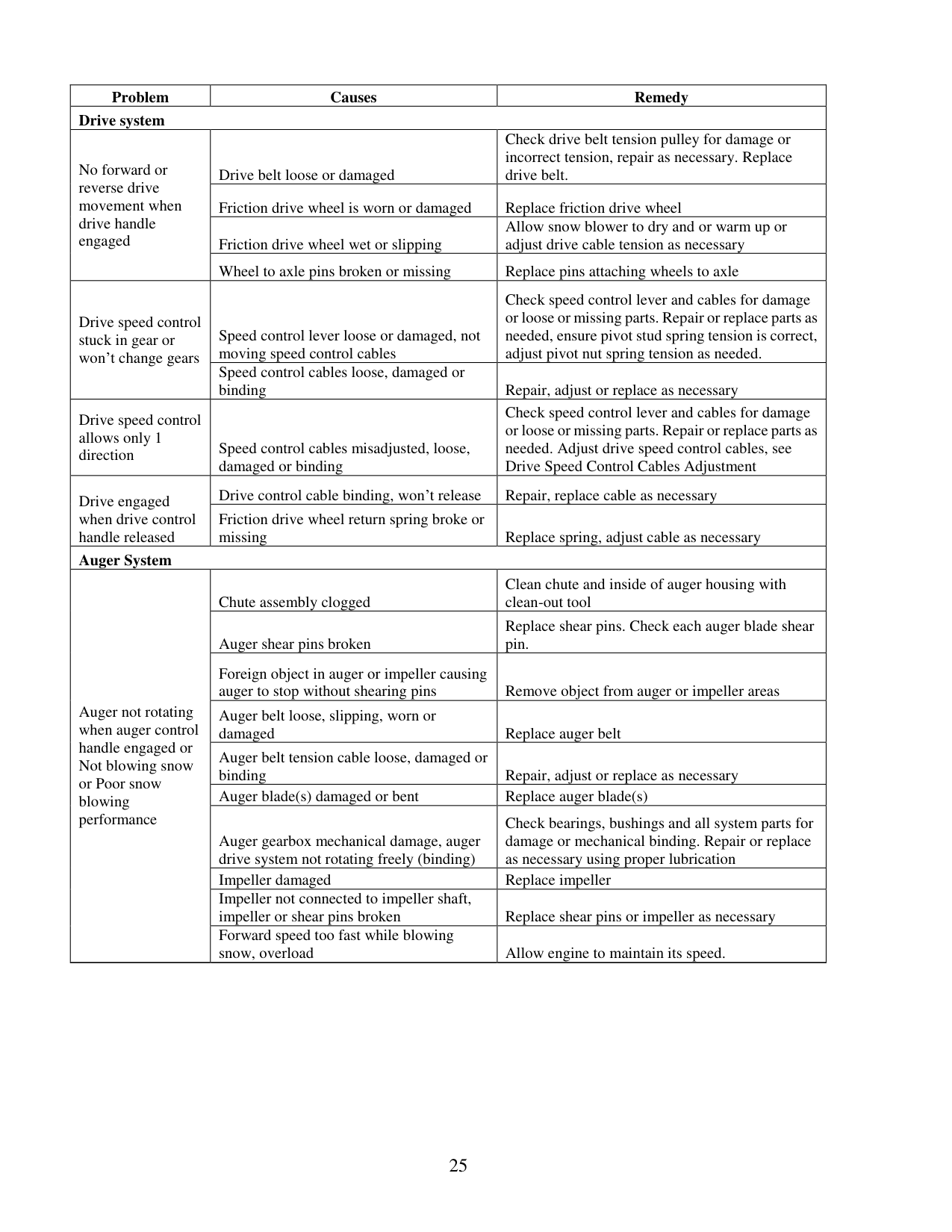
Problem Causes Remedy Drive system No forward or reverse drive movement when drive handle engaged Drive belt loose or damaged Check drive belt tension pulley for damage or incorrect tension, repair as necessary. Replace drive belt. Friction drive wheel is worn or damaged Replace friction drive wheel Friction drive wheel wet or slipping Allow snow blower to dry and or warm up or adjust drive cable tension as necessary Wheel to axle pins broken or missing Replace pins attaching wheels to axle Drive speed control stuck in gear or won’t change gears Speed control lever loose or damaged, not moving speed control cables Check speed control lever and cables for damage or loose or missing parts. Repair or replace parts as needed, ensure pivot stud spring tension is correct, adjust pivot nut spring tension as needed. Speed control cables loose, damaged or binding Repair, adjust or replace as necessary Drive speed control allows only 1 direction Speed control cables misadjusted, loose, damaged or binding Check speed control lever and cables for damage or loose or missing parts. Repair or replace parts as needed. Adjust drive speed control cables, see Drive Speed Control Cables Adjustment Drive engaged when drive control handle released Drive control cable binding, won’t release Repair, replace cable as necessary Friction drive wheel return spring broke or missing Replace spring, adjust cable as necessary Auger System Auger not rotating when auger control handle engaged or Not blowing snow or Poor snow blowing performance Chute assembly clogged Clean chute and inside of auger housing with clean-out tool Auger shear pins broken Replace shear pins. Check each auger blade shear pin. Foreign object in auger or impeller causing auger to stop without shearing pins Remove object from auger or impeller areas Auger belt loose, slipping, worn or damaged Replace auger belt Auger belt tension cable loose, damaged or binding Repair, adjust or replace as necessary Auger blade(s) damaged or bent Replace auger blade(s) Auger gearbox mechanical damage, auger drive system not rotating freely (binding) Check bearings, bushings and all system parts for damage or mechanical binding. Repair or replace as necessary using proper lubrication Impeller damaged Replace impeller Impeller not connected to impeller shaft, impeller or shear pins broken Replace shear pins or impeller as necessary Forward speed too fast while blowing snow, overload Allow engine to maintain its speed.
26
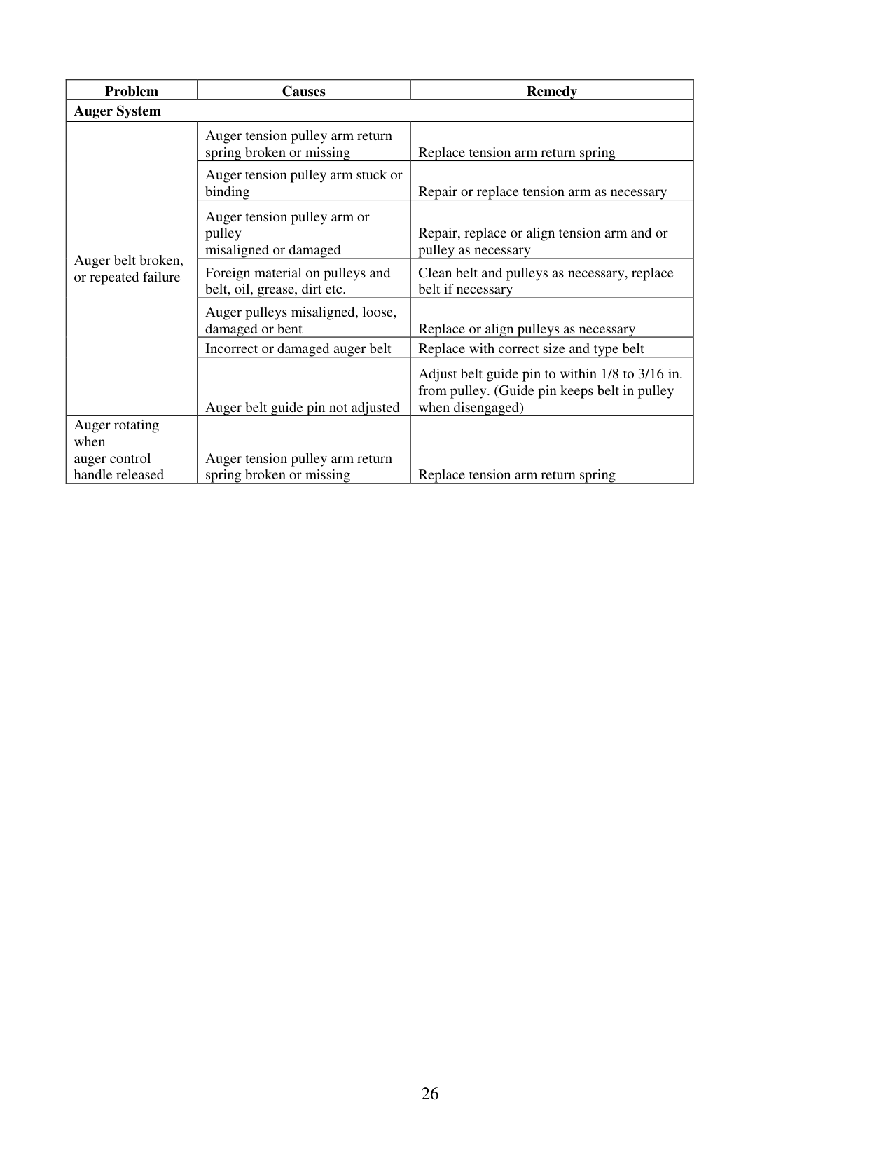
Problem Causes Remedy Auger System Auger belt broken, or repeated failure Auger tension pulley arm return spring broken or missing Replace tension arm return spring Auger tension pulley arm stuck or binding Repair or replace tension arm as necessary Auger tension pulley arm or pulley misaligned or damaged Repair, replace or align tension arm and or pulley as necessary Foreign material on pulleys and belt, oil, grease, dirt etc. Clean belt and pulleys as necessary, replace belt if necessary Auger pulleys misaligned, loose, damaged or bent Replace or align pulleys as necessary Incorrect or damaged auger belt Replace with correct size and type belt Auger belt guide pin not adjusted Adjust belt guide pin to within 1/8 to 3/16 in. from pulley. (Guide pin keeps belt in pulley when disengaged) Auger rotating when auger control handle released Auger tension pulley arm return spring broken or missing Replace tension arm return spring
27
Exploded View And Parts List
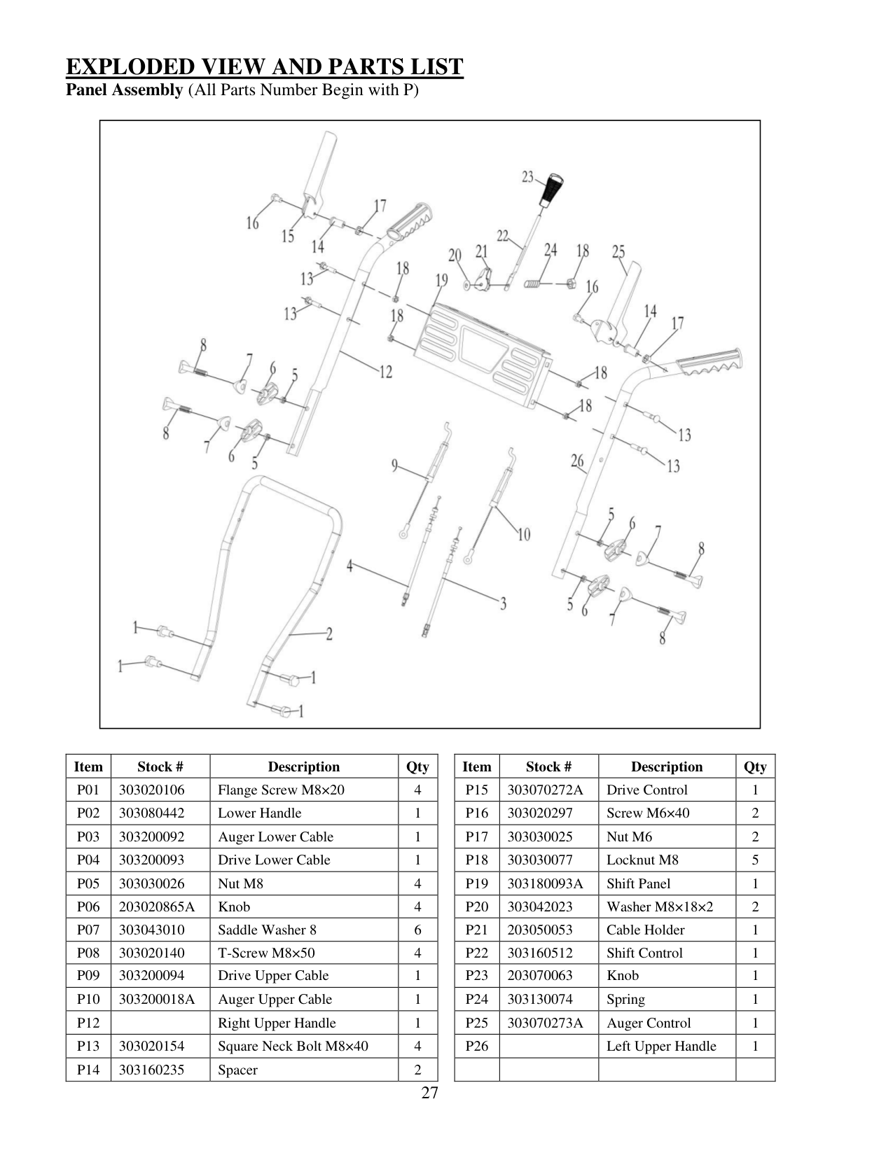
Panel Assembly (All Parts Number Begin with P)Item Stock # Description Qty Item Stock # Description Qty
P01
303020106 Flange Screw M8×20 4P15
303070272A
Drive Control 1P02
303080442 Lower Handle 1P16
303020297 Screw M6×40 2P03
303200092 Auger Lower Cable 1P17
303030025 Nut M6 2P04
303200093 Drive Lower Cable 1P18
303030077 Locknut M8 5P05
303030026 Nut M8 4P19
303180093A
Shift Panel 1P06
203020865A
Knob 4P20
303042023 Washer M8×18×2 2P07
303043010 Saddle Washer 8 6P21
203050053 Cable Holder 1P08
303020140 T-Screw M8×50 4P22
303160512 Shift Control 1P09
303200094 Drive Upper Cable 1P23
203070063 Knob 1P10
303200018A
Auger Upper Cable 1P24
303130074 Spring 1P12
Right Upper Handle 1
P25
303070273A
Auger Control 1P13
303020154 Square Neck Bolt M8×40 4P26
Left Upper Handle 1
P14
303160235 Spacer 2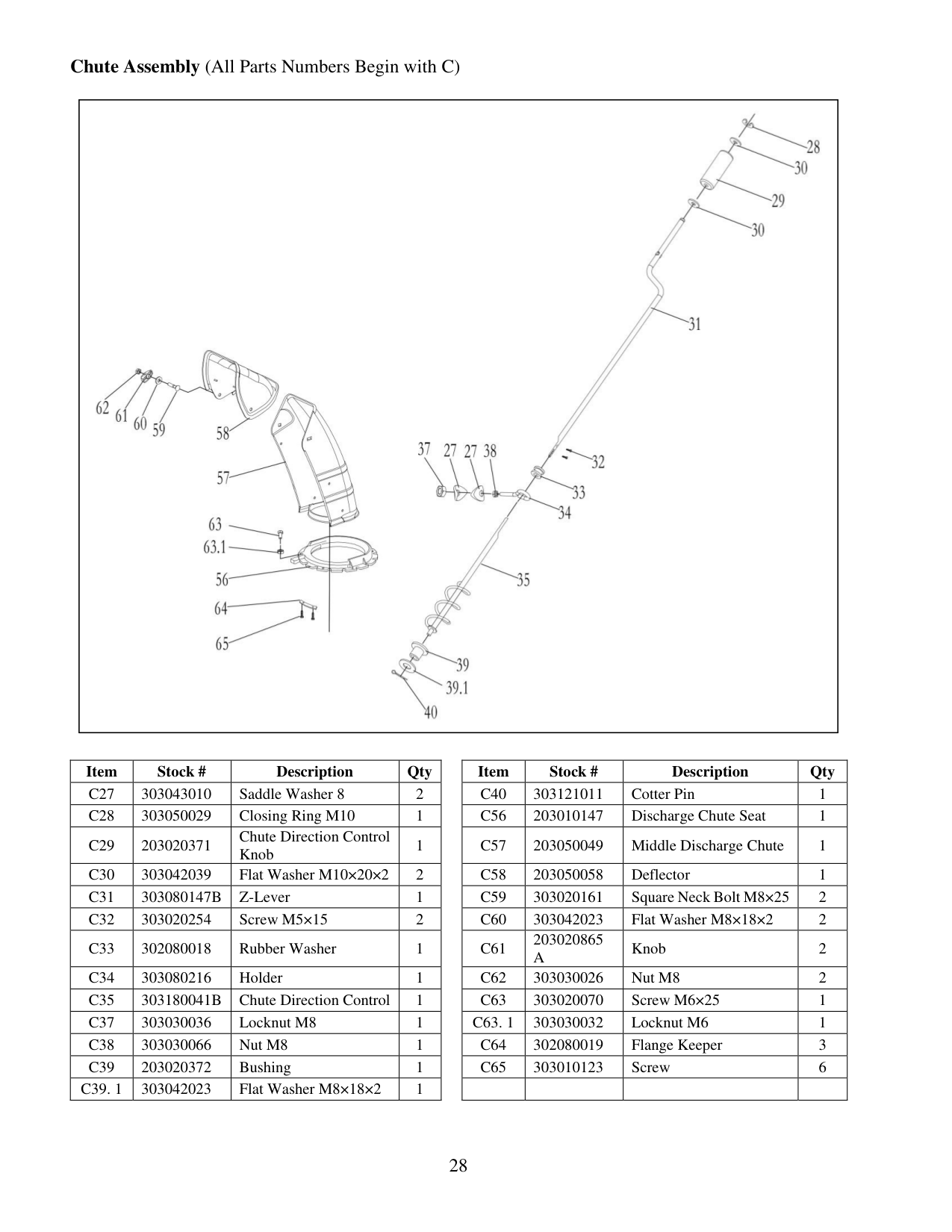
28 Chute Assembly (All Parts Numbers Begin with C)
Item Stock # Description Qty Item Stock # Description Qty
C27
303043010 Saddle Washer 8 2C40
303121011 Cotter Pin 1C28
303050029 Closing Ring M10 1C56
203010147 Discharge Chute Seat 1C29
203020371 Chute Direction Control Knob 1C57
203050049 Middle Discharge Chute 1C30
303042039 Flat Washer M10×20×2 2C58
203050058 Deflector 1C31
303080147B
Z-Lever 1C59
303020161 Square Neck Bolt M8×25 2C32
303020254 Screw M5×15 2C60
303042023 Flat Washer M8×18×2 2C33
302080018 Rubber Washer 1C61
203020865A
Knob 2C34
303080216 Holder 1C62
303030026 Nut M8 2C35
303180041B
Chute Direction Control 1C63
303020070 Screw M6×25 1C37
303030036 Locknut M8 1C63. 1
303030032 Locknut M6 1C38
303030066 Nut M8 1C64
302080019 Flange Keeper 3C39
203020372 Bushing 1C65
303010123 Screw 6C39. 1
303042023 Flat Washer M8×18×2 1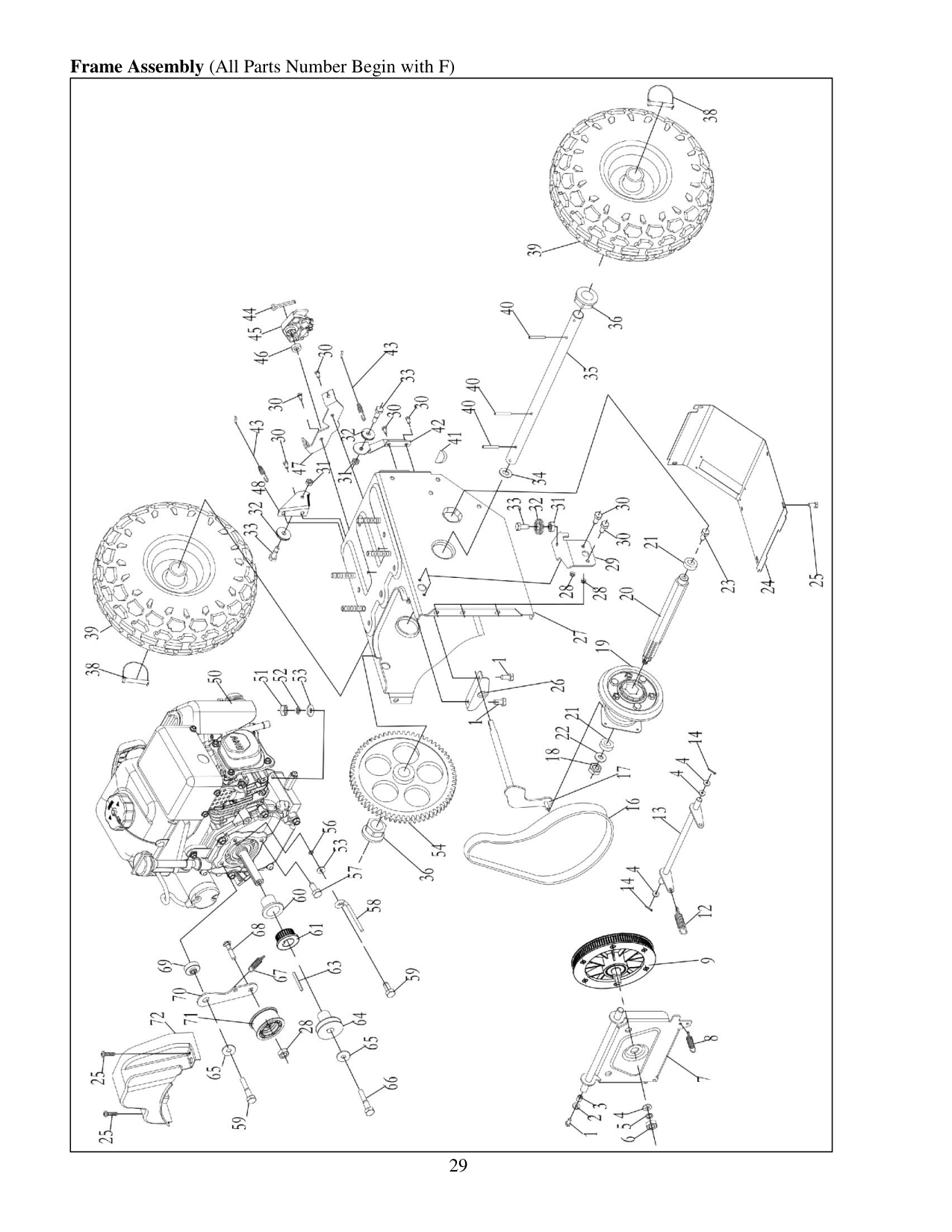
29 Frame Assembly (All Parts Number Begin with F)

30 Item Stock # Description Qty Item Stock # Description Qty
F01
303020492 Flange Screw M6×10 3F38
303122002 Dowel Pin 2F02
303042001 Flat Washer 6×16×1.5 1F39
302090139 Wheel 1F03
303160308 Spacer 1F40
303123008 Elastic Cylindrical Pin 5x30 3F04
303042039 Flat Washer 10×20×2 4F41
303110022 Woodruff Key 1F05
303041015 Spring Washer 10 1F42
303070134A
Guide Roller Bracket 1F06
303030068 Nut M10x1 1F43
303200012 Lower Auger Cable 2F07
303180274A
Friction Disk Bracket 1F44
303121004 Cotter Pin 2.5×30 1F08
303130072 Extension Spring 1F45
203020362A
Lower Shift Cable Control 1F09, 10,
11, 15 202160002 Synchronizing Wheel 1F46
303160385 Spacer 1F12
303130073 Extension Spring 2F47
303070206 Cable Bracket 1F13
303180037 Drive Bracket 1F48
303070418A
Guide Roller Bracket 1F14
303121011 Cotter Pin 1.8×25 2F50
303190063 Engine Assembly 1F16
302040026 Synchronous Belt 1F51
303042023 Flat Washer 8×18×2 4F17
303180027 Track Shift Rod Assembly 1F52
303041022 Spring Washer M8 5F18
303030059 Locknut M10 1F53
303030066 Nut M8 5F19
202170002 Friction Wheel Assembly 1F54
303160140 Big Gear 1F20
303160182 Wheel Drive Shaft 1F56
303043016 Lock Washer 8×15×0.5 1F21
303100051 Ball Bearing 6203-ZN 2F57
303160432 Screw M8X16 1F22
303042004 Flat Washer 10×22×2 1F58
303080144 Belt Keeper 1F23
303020494 Screw M10×16 1F59
303020265 Screw M8×30 2F24
303180463 Big Frame Cover 1F60
303060060 Spacer 1F25
303020248 Screw M6×12 8F61
303060041 Small Synchronous Pulley 1F26
303180028 Shift Frame Bracket 1F63
303110015 Woodruff Key 1F27
303180049 Frame Assembly 1F64
303160151 Pulley 1F28
303030077 Locknut M8 5F65
303042005 Flat Washer 8×28×3 1F29
303070133A
Guide Roller Bracket 1F66
303020124 Screw M8×35 1F30
303020246 Screw M6×16 8F67
303130094 Extension Spring 1F31
303030032 Locknut M6 3F68
303020154 Square Neck BoltM8×40
1F32
203020364 Guide Roller 3F69
303160191 Spacer 1F33
303160177 Screw 3F70
303070202 Small Flat Idler 1F34
303043018 Washer 20×32×2.5 1F71
303210045 Idler Arm 1F35
303160222 Wheel Shaft 1F72
203050051 Belt Cover 1F36
303060030 Hex Flange Bearing 2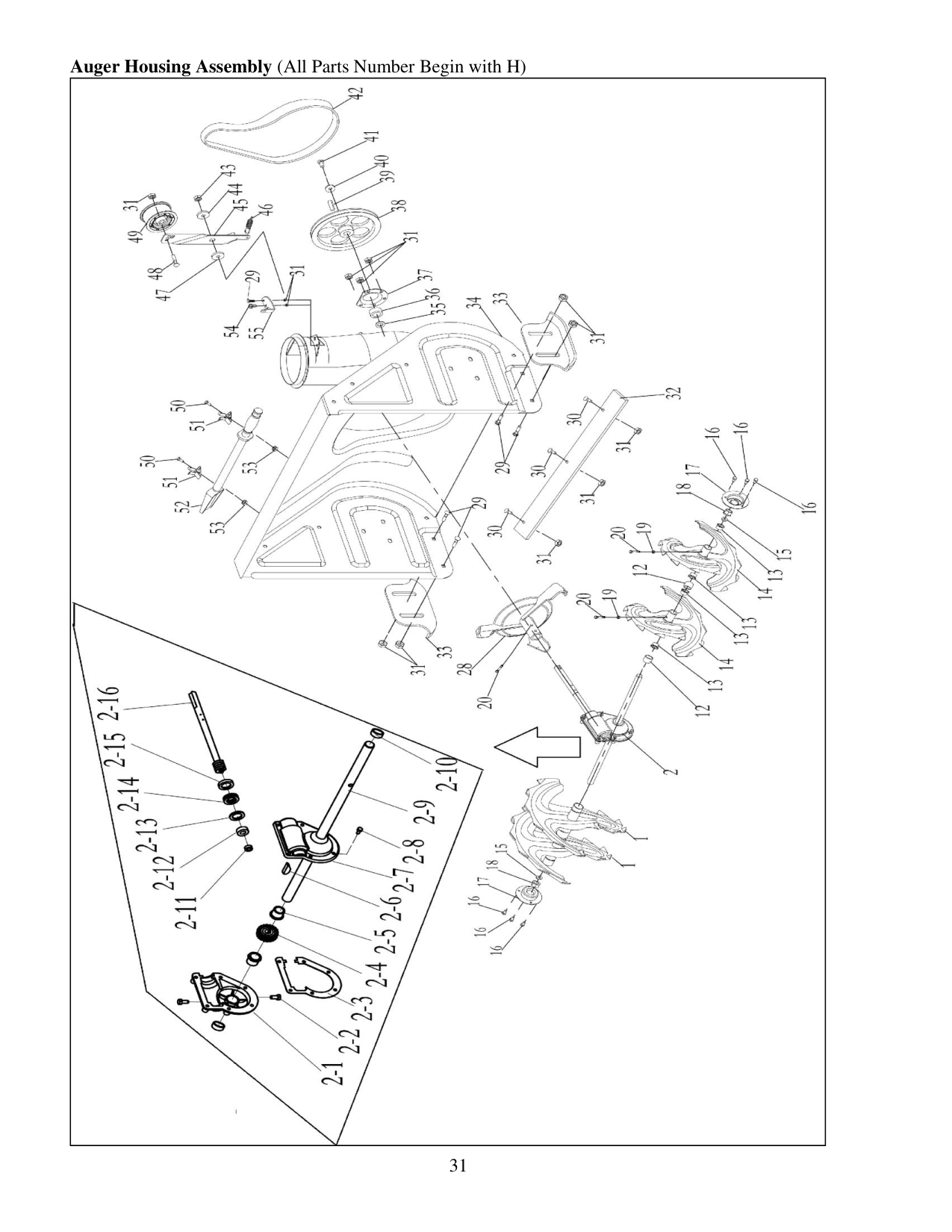
31 Auger Housing Assembly (All Parts Number Begin with H)

32
Item Stock # Description Qty Item Stock # Description Qty
H01
303180424 Single Auger Blade R 2H29
303020166 Square Neck Bolt M8×18 4H02
202450076 Gear Housing Assembly 1H30
303020332 Square Neck Bolt M8×16 6H02-1
303090031 Gear Housing R 1H31
303030077 Locknut M8 13H02-2
303020142 Plug Screw M8x10 2H32
303070936 Shave Plate 1H02-3
303070260 Seal 1H33
303070197 Skid Shoe 2H02-4
303090033 Gear 1H34
303180677 Auger Housing 1H02-5
303060055 Flange Bushing 2H35
303043018 Washer 2H02-6
303110022 Woodruff Key 1H36
303100040 Ball Bearing UC204 1H02-7
303090032 Gear Housing L 1H37
303070233 Keeper 1H02-8
303020489 Flange Bolt M6x18 6H38
303160143 Big Pulley 1H02-9
303160447 Auger Axle 1H39
303110014 Key C6X18 1H02-10
302130005 Reinforced Seal 2H40
303042005 Flat Washer 8×28×3 1H02-11
303100030 Ball Bearing 6001Z 1H41
303020279 Screw M8×25 1H02-12
303100035 Ball Bearing 6904Z 1H42
302040011 Auger Belt 880 1H02-13
303070179 Washer 1H43
303030708 Locknut M10 1H02-14
303100039 Ball Bearing 51104 1H44
303043019 Butterfly Washer 1H02-15
302130002 Reinforced Seal 1H45
303070126 Idler Arm 1H02-16
303160204 Worm Shaft 1H46
303160175 Extension Spring 1H12
203050108 Spacer 6H47
303160172 Bushing 1H13
203060012 Flange Bushing 8H48
303020154 Square Neck Bolt M8×40 1H14
303180425 Single Auger Blade L 2H49
303210045 Idler Arm 1H15
203050109 Spacer bush 2H50
303020213 Screw M6×12mm 2H16
303020493 Flang Bolt M8×16 6H51
303070170 Clean-out Tool Bracket 2H17
303070234 Bearing Housing 2H52
203050057 Clean-out Tool 1H18
203060013 Flange Bearing 2H53
303030087 Locknut M6 2H19
303030032 Locknut M6 5H54
303020280 Screw M8×18 1H20
303160355 Shear Pin 5H55
303070208 Bracket 1H28
303180080 Impeller 1
33
Two (2) Years Limited Warranty
PowerSmart is committed to building tools that are dependable for years. Our warranties are consistent with our commitment and dedication to quality.