
Stanley FatMax PP1DCS Portable Power Station Jump Starter
Ask AI
— answers from the official manualAnswers from the official manual.
Common questions
Common Questions
20 totalHow do I install the AAA batteries in my Stanley Fatmax Pp1dcs?
To install the AAA batteries, lift up the latch on the bottom of the stud sensor to unlock the battery compartment cover. Remove the cover and insert two new high-quality AAA batteries correctly according to the polarity markings inside the compartment. Replace the cover by pressing it down until securely locked in place (Page 5).
What should I do if my Stanley Fatmax Pp1dcs stud sensor starts blinking?
A blinking LED indicates low battery power. Check and ensure each battery is installed correctly, contacts are clean without rust or corrosion, and use new high-quality batteries to reduce the chance of leakage (Page 8).
How can I identify a stud using the Stanley Fatmax Pp1dcs?
Place your thumb on one side of the sensor, pointer finger and palm over the center, and rest fingers on the other side (Figure C). Position flat against the wall parallel to a door or window. Press and hold until all LEDs except Power turn off, then move SLOWLY to find the stud's center when LED illuminates with longer beep sound (Page 6).
What should I do if my Stanley Fatmax Pp1dcs doesn't detect studs?
Ensure batteries are working, position the sensor flat against drywall, move slowly while pressing center button, and verify wall thickness is within limits: STHT77587 up to 0.75" thick drywall; STHT77588 up to 1.5" (Page 9).
How can I determine the presence of live AC wires behind a wall with this stud sensor?
Holding it as instructed, slowly move the sensor across the wall while pressing and holding. If the AC LED illuminates, you are near 6-18" from active AC wire; AC LEDs along with center red LEDs indicate AC voltage at stud's center when detected (Pages 5-7).
What does it mean if the green Power LED on my Stanley Fatmax Pp1dcs isn't lighting up?
A non-functional green Power LED indicates no battery power. Install two new, high-quality AAA batteries to resolve this issue (Page 8).
Show 14 more questions
How should I maintain my Stanley Fatmax Pp1dcs?
What safety precautions should I take while using my Stanley Fatmax Pp1dcs?
What is the warranty period and how can I obtain it?
How deep of a wall can the Stanley Fatmax Pp1dcs detect studs?
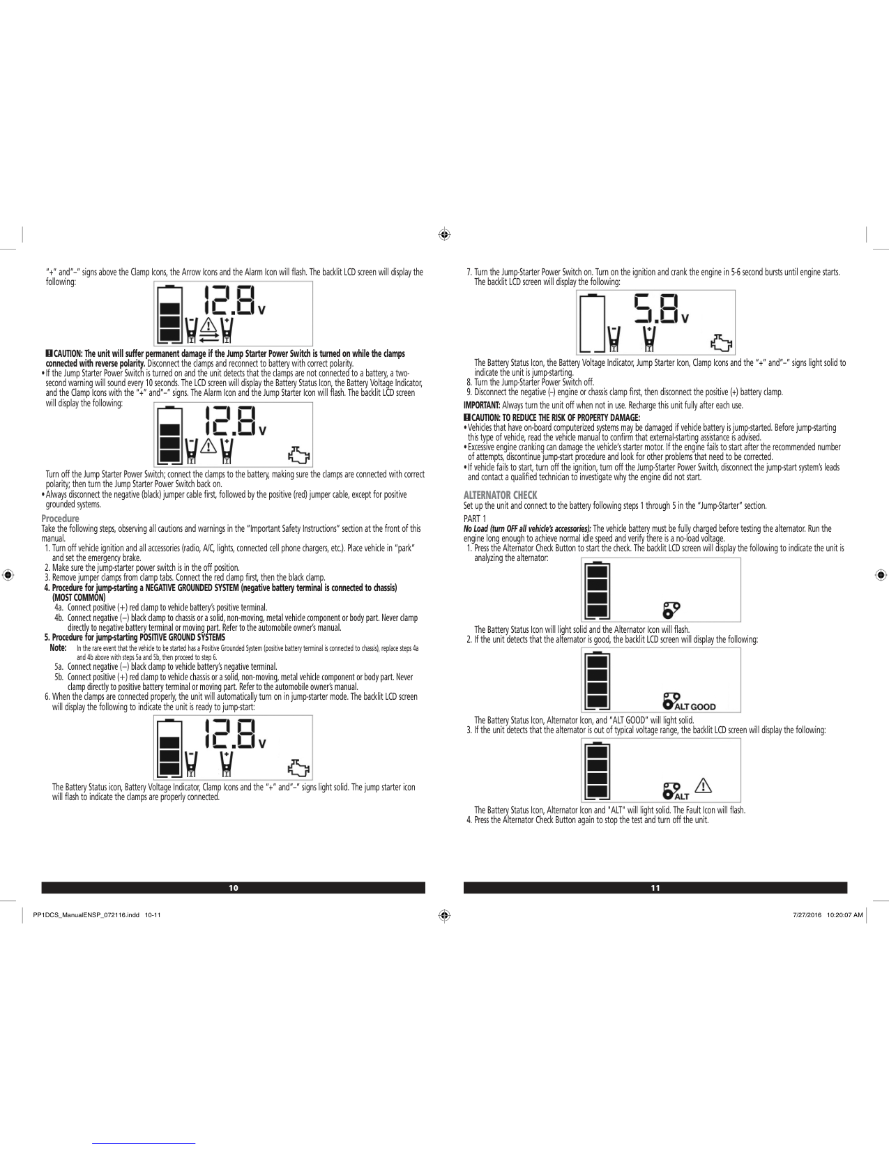
How do I use the Stanley FatMax PP1DCS jump starter?
What are the charging instructions for the Stanley FatMax professional power station?
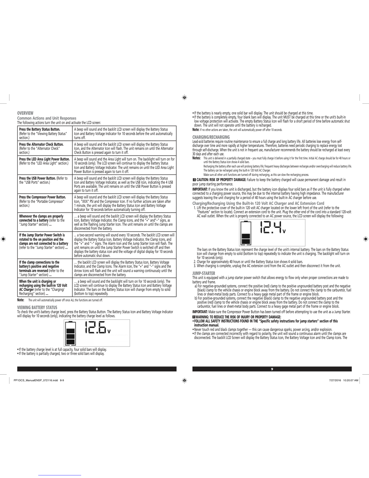
How do I check the battery status on the FatMax PP1DCS?
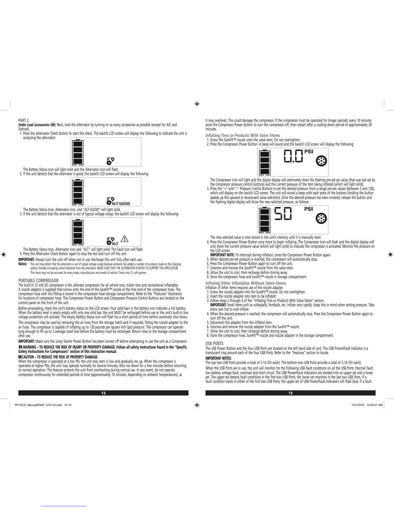
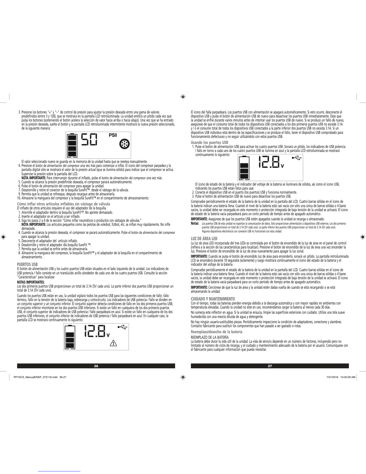
How do I use the portable compressor on the Stanley FatMax?
What should I do if the jump starter clamps are connected with reverse polarity?
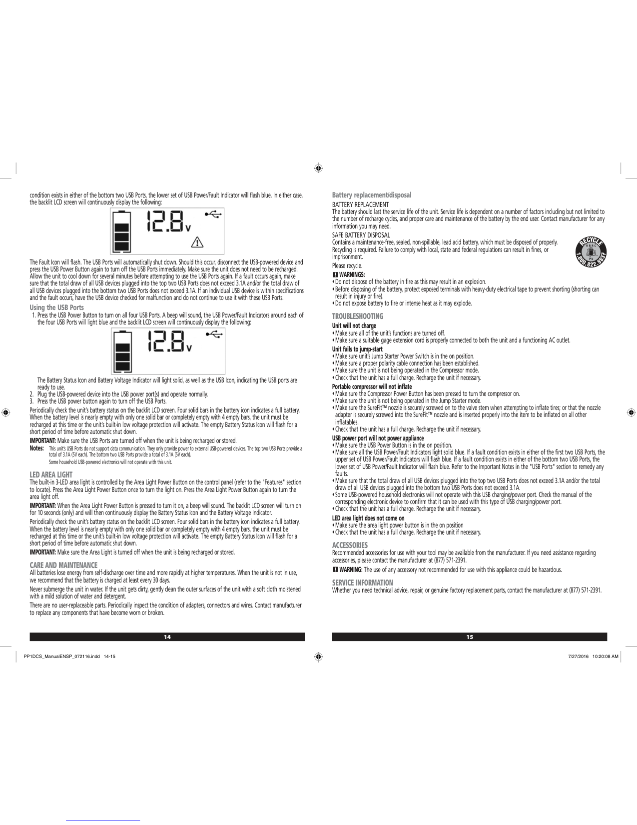
How do I use the USB ports on the FatMax PP1DCS?
What does it mean when the USB power/fault indicator flashes blue?
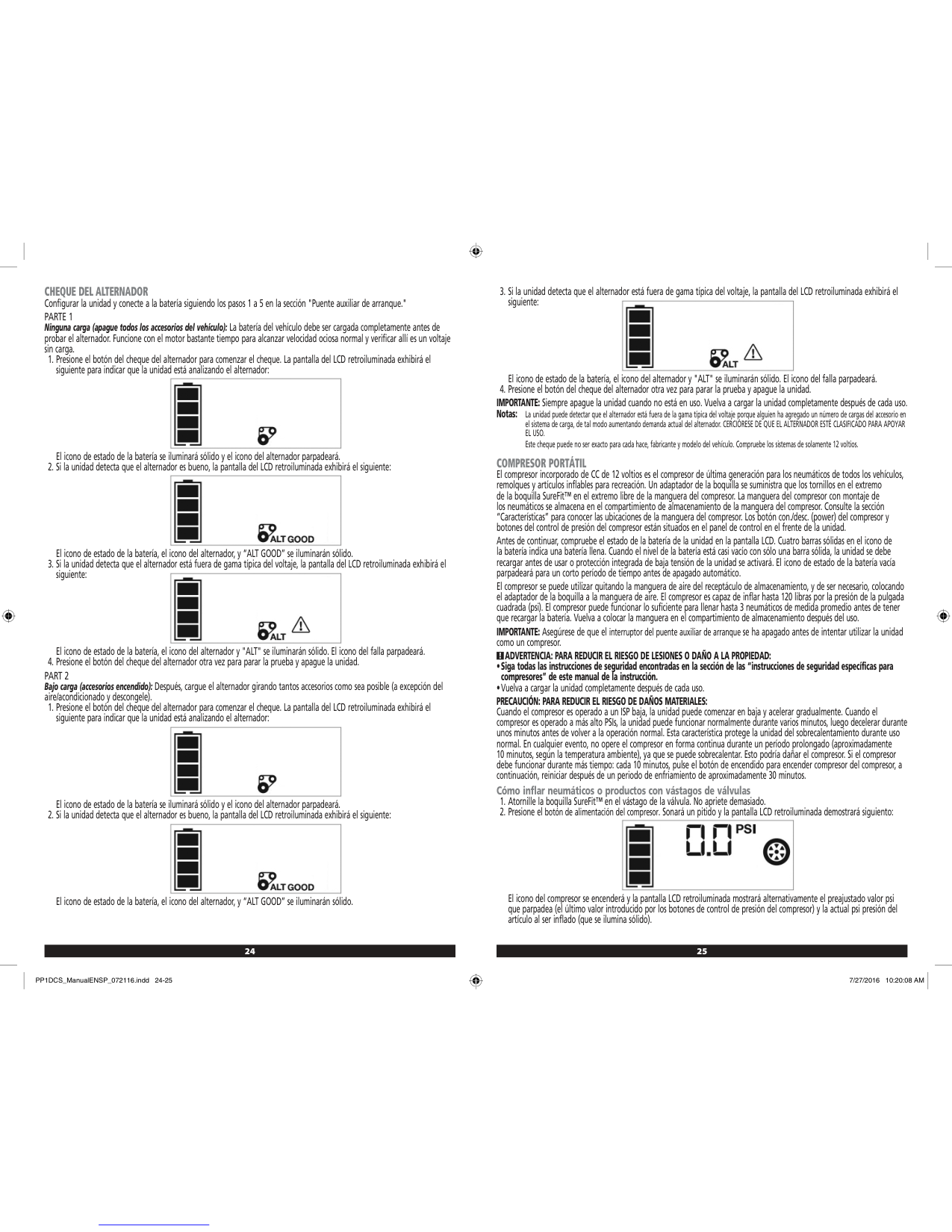
How do I perform an alternator check with the Stanley FatMax?
How often should I recharge the Stanley FatMax when not in frequent use?
What are the specifications and capabilities of the Stanley FatMax PP1DCS?
Full Manual
28 pages
STHT77587 & STHT77588
Stud Sensor
PT
ES
##### www.STANLEYTOOLS.com
Please read these instructions before operating the product.
A
2
1 3
4
5 7
AC
6
AC
B
+
######## -
|+
-| |---|
|+
-| |---|
C
| | |---|
| | |---|
D
|&| |---|
|&| |---|
EContents
####### If you have any questions or comments about this or any STANLEY® tool, go to http://www.STANLEYTOOLS.com.
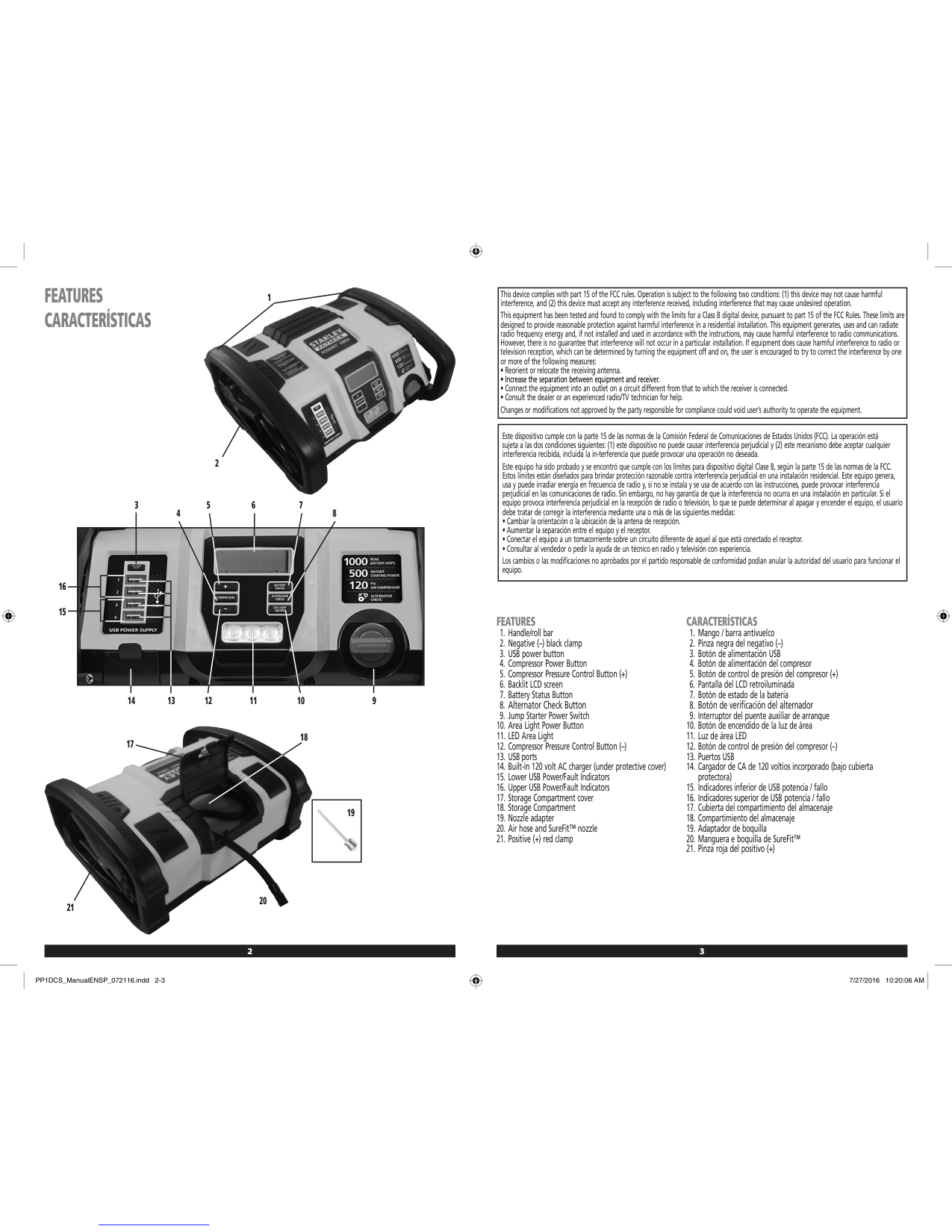
Stud Sensor Information
The Stud Sensor STHT77587/STHT77588 uses electronic signals to locate the center of wood or metal studs, or live AC wires through drywall or other common building materials.
PLEASE NOTE:
WARNING: Read and understand all instructions. Failure to follow the warnings and instructions in this manual may result in serious personal injury.
####### SAVE THESE INSTRUCTIONS
WARNING: The following label information can be found on your tool for your safety.
Made in China
|AAA| |---|
Made in China
|AAA| |---|
CAUTION: Protect your eyes. Wear safety goggles.
Once the center of a wood or metal stud has been detected in one pass across the surface, the Stud Sensor STHT77587/
WARNING: This tool is not a measuring device and should not be used as a substitute for a voltmeter.
WARNING: The LED or Live Wire Detection symbol on the display is just an indicator and in some situations the voltage detection option may not accurately indicate the presence of voltage in a wall in the event of internal device failure or improper operation, and therefore should not be solely relied upon for identification of the presence of hazardous voltages. Other evidence, such as construction blueprints or visual identification of wiring or conduit entry points should also be utilized.
User Safety
##### Safety Guidelines
The definitions below describe the level of severity for each signal word. Please read the manual and pay attention to these symbols.
WARNING: Indicates a potentially hazardous situation which, if not avoided, could result in serious injury.
CAUTION: Indicates a potentially hazardous situation which, if not avoided, may result in minor or moderate injury.
Always follow proper safety practices and use a separate detection method to verify a de-energized condition prior to commencing work.
NOTICE: Indicates a practice not related to personal injury which, if not avoided, may result in property damage.
Installing AAA Batteries
Load two new AAA batteries in the STHT77577 or STHT77588 stud sensor.
WARNING: Shielded wires or wires in metal conduits, casings, metalized walls, or thick, dense walls may not be detected.
CAUTION: Use personal protective equipment. Always wear eye protection. Depending on the work conditions, wearing protective equipment such as a dust mask, non-skid safety shoes, hard hat, and hearing protection will reduce the risk of personal injury.
IMPORTANT SAFETY NOTICE Ensure proper detection of live wires. Always hold the Stud Sensor STHT77587/STHT77588 in the handle area only. Grasp between fingers and thumb while making contact with your palm (Figure C ).
NOTE: Static electrical charges that can develop on drywall and other surfaces will spread the voltage detection area many inches on each side of the actual electrical wire. To aid in locating the wire position, scan holding the unit ½” (13mm) away from the wall surface or place your other hand on the surface approximately 12” (305mm) from the sensor.
Battery Safety
Using the Stud Sensor
####### WARNING: Batteries can explode, or leak, and can cause injury or fire. To reduce this risk:
The stud sensor will help you find wood or metal studs, and AC voltage behind drywall.
#### EFinding a Stud
C ).
A 3 ) will illuminate and you will hear a few short beeps.
5 ) will illuminate and the stud sensor will sound the short alternating beeps (AC found) followed by a longer constant beep (stud center found), and repeat these beeps until you stop pressing .
Maintenance
C ).
E Troubleshooting
##### The LED is Blinking The battery power is low.
##### The LED does not Turn On There is no battery power.
Service and Repairs
Note: Disassembling the tool will void all warranties on the product.
To assure product SAFETY and RELIABILITY, repairs, maintenance and adjustment should be performed by authorized service centers. Service or maintenance performed by unqualified personnel may result in a risk of injury. To locate your nearest STANLEY service center, go to http://www.STANLEYTOOLS.com.
Limited Warranty
During the period of one (1) year, if this product fails to perform due to defects in material or workmanship, we will replace it. DO NOT RETURN PRODUCT TO STORE. Please call 1-800-262-2161 (M-F, 8-5 EST) or visit www.STANLEYTOOLS.com for details.
##### The Stud Sensor is not Finding Studs
ESpecifications
| |STHT77587|STHT77588| |---|---|---| |Detect Wood Studs|up to .75” (19mm) thick drywall|up to 1” (25mm) thick drywall|
|Detect Metal Studs|up to .75” (19mm) thick drywall|up to 1.5” (38mm) thick drywall| |Detect Live AC Wire 110V @ 60 Hz (220V @ 50Hz)|up to 2” (50.8mm) thick drywall from a distance of 6”-18” (.15 m- .5 m) AC LED will illuminate|up to 2” (50.8mm) thick drywall from a distance of 6”-18” (.15 m- .5 m) AC LED will illuminate| |Accuracy - Center of Wood stud|+/- 1/4” (6.4mm) under 1/2” - 3/4” (12.7mm - 19mm) thick drywall|+/- 1/4” (6.4mm) under 1/2” - 1.5” (12.7mm - 38mm) thick drywall| |Accuracy - Center of Metal stud|+/- 1/4” (6.4mm) under 1/2” - 3/4” (12.7mm - 19mm) thick drywall|+/- 1/4” (6.4mm) under 1/2” - 1.5” (12.7mm - 38mm) thick drywall| |Power Source|2 AAA (1.5V) size batteries (3V DC)|2 AAA (1.5V) size batteries (3V DC)| |Battery Life|< 20 hrs of continual use at <2.4V (+/- 0.3V), Power LED will flash to indicate low battery
|< 20 hrs of continual use at <2.4V (+/- 0.3V), Power LED will flash to indicate low battery
| |Automatic Calibration|Yes|Yes| |Automatic Shutoff when release On button|Yes|Yes| |Non-marring Surface|Yes|Yes| |Relative Humidity|35% - 55%|35% - 55%| |Operating Temperature|32°F to 122°F (0°C to 50°C)|32°F to 122°F (0°C to 50°C)| |Storage Temperature|-67°F to 158°F (-55°C to 70°C)|-67°F to 158°F (-55°C to 70°C)|
Contenido
Información de Sensor de Postes
El sensor de postes STHT77587/STHT77588 utiliza señales electrónicas para ubicar el centro de los postes de madera o metal, o los cables de CA activos a través de paneles de yeso u otros materiales de construcción comunes.
TENGA EN CUENTA:
ES
Una vez que se ha detectado el centro de un poste de madera o metal en una pasada a través de la superficie, el sensor de postes STHT77587/STHT77588 enciende un LED y emite un tono audible. Un orificio de marcado le permite indicar fácilmente el centro del poste
Seguridad del usuario
##### Guías de Seguridad
Las siguientes definiciones describen el nivel de severidad para cada palabra de señal. Por favor lea el manual y ponga atención a estos símbolos.
ADVERTENCIA: Indica una situación potencialmente peligrosa que, si no se evita, podría resultar en lesiones serias.
PRECAUCIÓN: Indica una situación potencialmente peligrosa que, si no se evita, puede resultar en lesiones menores o moderadas.
AVISO: Indica una práctica no relacionada con lesiones personales que, si no se evita, puede resultar en daño a la propiedad.
Si tiene cualquier pregunta o comentario sobre esta o cualquier herramienta STANLEY®, visite http://www.STANLEYTOOLS.com.
ADVERTENCIA: Lea y entienda todas las instrucciones. La falla en seguir las advertencias e instrucciones en este manual puede resultar en lesiones personales serias.
####### CONSERVE ESTAS INSTRUCCIONES
ADVERTENCIA: La información de la etiqueta siguiente se puede encontrar en su herramienta para su seguridad.
Made in China
|AAA| |---|
Made in China
|AAA| |---|
PRECAUCIÓN: Proteja sus ojos. Use gafas de seguridad.
ADVERTENCIA: Esta herramienta no es un dispositivo de medición y no debe usarse como sustituto de un voltímetro.
ADVERTENCIA: El LED o el símbolo Live Wire Detection en la pantalla es sólo un indicador y en algunas situaciones la opción de detección de voltaje puede no indicar con precisión la presencia de voltaje en una pared en caso de falla interna del dispositivo
Siempre siga las prácticas de seguridad adecuadas y use un método de detección separado para verificar una condición de desenergización antes de comenzar a trabajar.
ADVERTENCIA: Siempre apague la energía CA cuando trabaje cerca del cableado.
ADVERTENCIA: Es posible que no se detecten cables o cables blindados en los conductos metálicos, carcazas, paredes metalizadas o paredes gruesas y densas.
PRECAUCIÓN: Use equipo de protección personal. Siempre use protección para los ojos. Dependiendo de las condiciones de trabajo, usar equipo de protección tal como una máscara de polvo, zapatos de seguridad anti-deslizantes, casco, y protección auditiva reducirá el riesgo de lesiones personales.
AVISO DE SEGURIDAD IMPORTANTE Asegure la detección adecuada de cables activos. Siempre sostenga el sensor de postes STHT77587/STHT77588 únicamente en el área de la manija. Sujete entre los dedos y el pulgar mientras hace contacto con la palma (Figura C ).
NOTA: Las cargas eléctricas estáticas que pueden desarrollarse en los paneles de yeso y otras superficies extenderán el área de detección de voltaje varias pulgadas a cada lado del cable eléctrico real. Para ayudar a ubicar la posición del cable, escanee sosteniendo la unidad a ½" (13 mm) de distancia de la superficie de la pared o coloque la otra mano sobre la superficie a aproximadamente a 12" (305 mm) del sensor.
Seguridad de la batería
ADVERTENCIA: Las baterías pueden explotar, o tener fugas, y pueden causar lesiones personales o incendios. Para reducir este riesgo:
ES
Instalación de Baterías AAA
Cargue dos baterías AAA nuevas en el sensor de postes STHT77577 o STHT77588.
ES
se debe iluminar para indicar que las baterías están en buenas condiciones. Si este LED parpadea o no se ilumina, cambie las baterías.
Uso del Sensor de Postes
El sensor de postes lo ayudará a encontrar postes de madera o metal y voltaje CA detrás de paneles de yeso.
##### Encontrar CA activa
hasta que todos los LED (excepto el LED verde de encendido) se apaguen (1 seg.).
##### Encontrar un Poste
Solución de problemas
3 ) comenzará a iluminarse y el sensor de postes proporcionará un sonido con ritmo desde 12”-18” (0.3 m - 0.5 m), una distancia típica desde el voltaje CA activo. Debido a que los cables de CA generalmente están conectados a los postes, los LED direccionales lo ayudarán a encontrar cables de CA activo que pueden estar conectados al poste más cercano.
El LED parpadea La energía de la batería es baja.
ES
El LED no enciende No hay energía de la batería.
##### El sensor de postes no encuentra postes
Mantenimiento
ES
Servicio y reparaciones
Nota: Desensamblar la herramienta anulará todas las garantías del producto.
Para garantizar la SEGURIDAD y CONFIABILIDAD del producto, las reparaciones, el mantenimiento y el ajuste deben ser realizados por centros de servicio autorizados. El servicio o mantenimiento realizado por personal no calificado puede ocasionar lesiones. Para localizar a su centro de servicio STANLEY más cercano, visite HTTP://WWW.StanleyTOOLS.com.
Garantía Limitada
Durante el período de un (1) año, si este producto no funciona debido a defectos en el material o mano de obra, lo reemplazaremos. NO DEVUELVA EL PRODUCTO A LA TIENDA. Llame al 1-800-262-2161 (Lunes a viernes, 8-5 EST) o visite www.STANLEYTOOLS.com para obtener más detalles.
Especificaciones
| |STHT77587|STHT77588| |---|---|---| |Detectar postes de madera|panel de yeso de hasta 0.75” (19mm) de espesor|panel de yeso de hasta 1” (25mm)| |Detectar postes de metal|panel de yeso de hasta 0.75” (19mm) de espesor|panel de yeso de hasta 1.5” (38mm)| |Detectar cable de CA activo 110V @ 60 Hz (220V @ 50Hz)|panel de yeso hasta 2” (50.8mm) de espesor desde una distancia de 6”-18” (0.15 m - 0.5 m) se iluminará el LED de CA|panel de yeso hasta 2” (50.8mm) de espesor desde una distancia de 6”-18” (0.15 m - 0.5 m) se iluminará el LED de CA| |Precisión - Centro de Poste de madera|+/- 1/4” (6.4mm) bajo panel de yeso de 1/2” - 3/4” (12.7mm - 19mm) de espesor|+/- 1/4” (6.4mm) bajo panel de yeso de 1/2” - 1.5” (12.7mm - 38mm) de espesor| |Precisión - Centro de Poste de metal|+/- 1/4” (6.4mm) bajo panel de yeso de 1/2” - 3/4” (12.7mm - 19mm) de espesor|+/- 1/4” (6.4mm) debajo de panel de yeso de 1/2” - 1.5” (12.7mm - 38mm) de espesor| |Fuente de energía|2 baterías tamaño AAA (1.5V) (3V CD)|2 baterías tamaño AAA (1.5V) (3V CD)| |Vida de batería|< 20 hrs de uso continuo en <2.4V (+/- 0.3V), el LED de Energía parpadeará para indicar batería baja
|< 20 hrs de uso continuo en <2.4V (+/- 0.3V), el LED de Energía parpadeará para indicar batería baja
|
|Calibración automática|Sí|Sí| |Apagado automático cuando se libera el botón de encendido|Sí|Sí| |Superficie de protección|Sí|Sí| |Humedad relativa|35% - 55%|35% - 55%| |Temperatura de operación|32°F a 122°F (0°C a 50°C)|32°F a 122°F (0°C a 50°C)| |Temperatura de almacenamiento|-67°F a 158°F (-55°C a 70°C)|-67°F a 158°F (-55°C a 70°C)|
ES
Table des matières
F
Renseignements sur le détecteur de montants Le détecteur de montants STHT77587/STHT77588 utilise des signaux électroniques pour localiser le centre des montants en bois ou en métal, ou les fils sous tension à travers la cloison sèche ou d’autres matériaux de construction courants. VEUILLEZ NOTER :
Une fois que le centre d’un montant en bois ou en métal a été détecté en un seul passage sur la surface, le détecteur de montants STHT77587/STHT77588 allume un voyant DEL et émet une tonalité audible. Un trou de repérage vous permet d’indiquer facilement le centre du montant
Sécurité de l'utilisateur
##### Directives sur la sécurité
Les définitions suivantes décrivent le niveau de sévérité pour chaque mot-indicateur. Veuillez lire le manuel et porter attention à ces symboles.

AVERTISSEMENT : Indique une situation potentiellement dangereuse qui, si elle ne peut être évitée, pourrait entraîner des blessures graves.
ATTENTION : Indique une situation potentiellement dangereuse qui, si elle n’est pas évitée, peut entraîner une blessure légère ou modérée.
AVIS : Indique une pratique non liée à une blessure corporelle qui, si elle n’est pas évitée, peut entraîner des dommages matériels.
Si vous avez des questions ou des commentaires sur cet outil ou tout autre outil STANLEY®, visitez le http://www.STANLEYTOOLS.com.
AVERTISSEMENT : Lisez et comprenez toutes les instructions. Ne pas suivre les avertissements et les instructions de ce manuel peut entraîner une blessure corporelle grave.
####### CONSERVEZ CES INSTRUCTIONS
AVERTISSEMENT : Les informations suivantes sur l’étiquette peuvent être trouvées sur votre outil pour votre sécurité.
Made in China
|AAA| |---|
Made in China
|AAA| |---|
ATTENTION : Protégez vos yeux. Portez des lunettes de sécurité.
AVERTISSEMENT : Cet outil n’est pas un instrument de mesure et ne doit pas être utilisé pour remplacer un voltmètre.
Sécurité concernant les piles
AVERTISSEMENT : Le voyant DEL ou le symbole détection de fils sous tension sur l’affichage est simplement un indicateur et, dans certaines situations, l’option de détection de la tension peut ne pas indiquer avec précision la présence de la tension dans un mur en cas de défaillance interne de l’appareil ou d’une mauvaise utilisation et, par conséquent, ne doit pas être seulement utilisée pour l’identification de la présence de tensions dangereuses. D'autres éléments, comme les plans de construction ou l’identification visuelle des points d’entrée des fils ou des conduits, doivent aussi être utilisés.
####### AVERTISSEMENT : Les piles peuvent exploser ou fuir et causer une blessure ou un incendie. Afin de réduire ce risque :
F

Appliquez toujours les pratiques de sécurité appropriées et utilisez une méthode de détection séparée pour vous assurer qu’il n’y a pas de tension avant de commencer à travailler.
AVERTISSEMENT : Coupez toujours l’alimentation CA lorsque vous travaillez près des fils.
AVERTISSEMENT : Les fils blindés ou des fils dans des conduits métalliques, les boîtiers, les murs métallisés ou les murs denses et épais peuvent ne pas être détectés.
Installer des piles AAA
Insérez deux nouvelles piles AAA dans le détecteur de montants STHT77577 ou STHT77588.
ATTENTION : Utilisez un équipement de protection individuel. Portez toujours une protection oculaire. Selon les conditions de travail, porter un équipement de protection comme un masque antipoussières, des chaussures de sécurité antidérapantes, un casque de sécurité et une protection auditive réduira le risque de blessure corporelle.
AVIS IMPORTANT DE SÉCURITÉ Assurez-vous de bien détecter les fils sous tension. Tenez toujours le détecteur de montants STHT77587/STHT77588 seulement par la poignée. Saisissez-la entre vos doigts et votre pouce tout en effectuant un contact avec votre paume (Figure C ).
REMARQUE : Des charges d’électricité statique qui peuvent se développer sur la cloison sèche et d’autres surfaces étendront la zone de détection de la tension de plusieurs pouces de chaque côté du fil électrique actuel. Pour aider à localiser la position des fils, balayez en tenant l’unité à ½ po (13mm) de la surface du mur ou placez votre autre sur la surface à environ 12 po (305mm) du détecteur.

Utiliser le détecteur de montants
Le détecteur de montants vous aidera à trouver les montants en bois ou en métal et la tension alternative derrière la cloison sèche.

##### Trouver le courant alternatif
##### Trouver un montant
Entretien

Dépannage
##### Le voyant DEL clignote La pile est faible.
F
Le voyant DEL ne s'allume pas Il n’y a plus d’alimentation provenant des piles.
##### Le détecteur de montants ne trouve pas de montants

fonctionnement et l’humidité relative indiquées.
F
Réparations
Remarque : Désassembler l’outil annulera toute garantie sur le produit.
Pour assurer la SÉCURITÉ et la FIABILITÉ du produit, les réparations, l’entretien et l’ajustement doivent être effectués par des centres de services autorisés. Les réparations ou l’entretien effectué par du personnel non qualifié peuvent entraîner un risque de blessure. Pour localiser le centre de service STANLEY le plus près, consultez http://www.STANLEYTOOLS.com.
Garantie limitée
Durant la période de un (1) an, si le produit ne fonctionne pas en raison de défauts de matériau ou de main-d’œuvre, nous le replacerons. NE PAS RETOURNER LE PRODUIT AU MAGASIN. Veuillez téléphoner au 1-800-262-2161 (L-V, 8 à 17 h EST) ou visitez www.STANLEYTOOLS.com pour des détails.
Caractéristiques
| |STHT77587|STHT77588| |---|---|---| |Détecter les montants en bois|cloison sèche d’une épaisseur allant jusqu’à 0,75 po (19 mm)|cloison sèche d’une épaisseur allant jusqu’à 1 po (25 mm)| |Détecter les montants en métal|cloison sèche d’une épaisseur allant jusqu’à 0,75 po (19 mm)|cloison sèche d’une épaisseur allant jusqu’à 1,5 po (38 mm)| |Détecter les fils de courant alternatif 110 V @ 60 Hz (220 V @ 50 Hz)|cloison sèche d’une épaisseur allant jusqu’à 2 po (50,8 mm) d’une distance de 6 à 18 po (0,15 à 0,5 m) le voyant de courant alternatif s’allumera|cloison sèche d’une épaisseur allant jusqu’à 2 po (50,8 mm) d’une distance de 6 à 18 po (0,15 à 0,5 m) le voyant de courant alternatif s’allumera| |Précision - Centre du montant en bois|+/- 1/4 po (6.4 mm) sous une cloison sèche d’une épaisseur de 1/2 à 3/4 po (12,7 à 19 mm)|+/- 1/4 po (6.4 mm) sous une cloison sèche d’une épaisseur de 1/2 à 1,5 po (12,7 à 38 mm)| |Précision - Centre du montant en métal|+/- 1/4 po (6.4 mm) sous une cloison sèche d’une épaisseur de 1/2 à 3/4 po (12,7 à 19 mm)|+/- 1/4 po (6.4 mm) sous une cloison sèche d’une épaisseur de 1/2 à 1,5 po (12,7 à 38 mm)| |Source de l'alimentation|2 piles AAA (1,5 V) (3 V CC)|2 piles AAA (1,5 V) (3 V CC)| |Durée de vie de la pile|< 20 heures d’utilisation continue à < 2,4 V (+/- 0.3V), le voyant DEL d’alimentation clignotera pour indiquer que la pile est faible
|< 20 heures d’utilisation continue à < 2,4 V (+/- 0.3V), le voyant DEL d’alimentation clignotera pour indiquer que la pile est faible
| |Calibrage automatique|Oui|Oui| |S’éteint automatiquement lorsque vous relâchez le bouton Marche|Oui|Oui| |Surface non marquante|Oui|Oui| |Humidité relative|35 % à 55 %|35 % à 55 %| |Température de fonctionnement|32°F à 122°F (0°C à 50°C)|32°F à 122°F (0°C à 50°C)| |Température d'entreposage|-67°F à 158°F (-55°C à 70°C)|-67°F à 158°F (-55°C à 70°C)|
F
Índice
CUIDADO: Indica uma situação potencialmente perigosa que, se não for evitada, talvez resulte em ferimentos leves ou moderados.

NOTA: Indica uma prática não relacionada a uma lesão corporal, a qual, se não evitada, poderá causar danos materiais.
PT
Se tiver perguntas ou comentários sobre esta ou outra ferramenta da STANLEY®, visite a página http://www.STANLEYTOOLS.com.
AVISO: Leia e entenda todas as instruções. O descumprimento dos avisos e das instruções deste manual pode causar sérias lesões corporais.
Informações sobre o detector de metal
####### GUARDE ESTAS INSTRUÇÕES
O detector de metal STHT77587 e STHT77588 usa sinais eletrônicos para localizar o centro da madeira e metais ou detectar fios energizados AC na parede ou outros materiais de construção comuns.
AVISO: As seguintes informações da etiqueta podem ser encontradas em sua ferramenta para sua segurança.
####### OBSERVAÇÃO:
Made in China
|AAA| |---|
Made in China

Assim que o centro de um pino de madeira ou metal tiver sido detectado depois de passar pela superfície, o detector de metal STHT77587 / STHT77588 acenderá uma lâmpada LED e emitirá um tom audível. Um circulo de marcação permite notar facilmente o centro do pino
|AAA| |---|
CUIDADO: Proteja seus olhos. Use óculos de segurança.
AVISO: Esta ferramenta não é um dispositivo de medição e não deve ser usada como substituto de um voltímetro.
Segurança do Usuário
##### Guia de segurança
As definições abaixo descrevem o nível de gravidade representado para cada palavra de sinal. Por favor, leia o manual e preste atenção nestes símbolos.
AVISO: Indica uma situação potencialmente perigosa que, se não for evitada, poderá resultar em ferimentos graves.
Segurança da Bateria
AVISO: O símbolo LED ou de detecção de fios mostrado no visor é apenas um indicador e em algumas situações, a opção de detecção de voltagem pode não indicar com exatidão a presença de tensão em uma parede, no caso de falha interna do dispositivo ou operação inadequada. Portanto, não se deve ser apenas confiar unicamente nele para identificar o risco de voltagens. Outras indicações, como desenhos técnicos da construção ou identificação visual de fiações ou conduítes nos pontos de entrada devem também ser utilizados.
AVISO: As baterias podem explodir ou vazar substâncias, e causar ferimentos graves ou incêndio. Para reduzir o risco:
PT
Sempre siga as instruções de segurança adequadas e use um método de detecção separado para verificar se os cabos estão desligados antes de iniciar o trabalho.

AVISO: Sempre desligue a energia AC ao trabalhar perto da fiação.
AVISO: Fios blindados ou fios em conduítes metálicos, invólucros, paredes metalizadas ou paredes grossas e densas podem não ser detectados.
Como instalar baterias AAA
CUIDADO: Use equipamento de proteção pessoal. Sempre use proteção ocular. Dependendo das condições de trabalho, use equipamentos de proteção pessoal, como máscara contra a poeira, sapatos de segurança antideslizantes, capacete e proteção auditiva para reduzir o risco de lesões corporais.
Carregue as baterias novas no detector de metal AAA no STHT77577 ou STHT77588.
AVISO IMPORTANTE DE SEGURANÇA Garanta a detecção adequada de fios energizados. Sempre segure o detector de metal STHT77587/STHT77588 somente pela empunhadura. Segure-o entre os dedos e o polegar encostando na palma da mão (Figura C ).
NOTA: As cargas elétricas estáticas, que podem se desenvolver em paredes de gesso e outras superfícies, espalharão a área de detecção de voltagem em muitas polegadas para todos os lados do fio elétrico em questão. Para ajudar a localizar a posição do fio, faça uma varredura segurando a unidade ½ (13 mm) da superfície da parede ou coloque a outra mão na sua superfície aproximadamente 12’’ (305 mm) do sensor.
####### B 5 ).
PT

Como usar o detector de metal
O detector de metal o ajudará a encontrar pinos de madeira ou metal, e voltagem AC presente em uma parede.
##### Como encontrar um pino

do pino.
##### Como encontrar um fio energizado AC
Solução de problemas
##### O LED está piscando A bateria está acabando.
PT

O LED não liga A bateria está descarregada.
5 ) acenderão e o detector emitirá o alarme sonoro curto alternado (AC encontrado) de pois outro mais constante e longo (centro do pino encontrado) e repetirá esses alarmes sonoros até você parar de pressionar
.
##### O detector de metal não está encontrando metal
Manutenção
Assistência técnica e Reparos Nota: Desmontar o instrumento anula todas as garantias do produto.
PT
Para garantir a SEGURANÇA e CONFIABILIDADE do produto, os reparos, a manutenção e os ajustes devem ser realizados por centros de assistência técnica autorizados. A assistência técnica ou manutenção realizada por pessoal não qualificado pode oferece riscos de lesões. Para localizar um centro de assistência técnica STANLEY MAIS PRÓXIMO DE VOCÊ, acesse HTTP://WWW.Stanley.com.
Garantia limitada
Durante o período de um (1) ano, se este produto não funcionar devido a defeitos de material ou mão-de-obra, nós o substituiremos. NÃO DEVOLVA O PRODUTO PARA LOJA. Ligue para 1-800-262-2161 (M-F, 8-5 EST) ou visite www.STANLEYTOOLS.com para mais detalhes.
Especificações
| |STHT77587|STHT77588| |---|---|---| |Detectar pinos de madeira|paredes de até 0,75” (19 mm) de espessura|paredes de até 0,1” (25 mm) de espessura| |Detectar pinos de metal|paredes de até 0,75” (19 mm) de espessura|paredes de até 1,5” (38 mm) de espessura| |Detectar Fio AC energizado 110V @ 60 Hz (220V @ 50Hz)|até paredes de 2” (50,8 mm) espessura de uma distância de 6”-18” (0,15 m - 0,5 m) o LED AC ascenderá|até paredes de 2” (50,8 mm) espessura de uma distância de 6”-18” (0,15 m - 0,5 m) o LED AC ascenderá| |Exatidão - Centro do pino de madeira|parede de +/- 1/4” (6.4 mm) menor que 1/2” - 3/4” (12,7 mm - 19 mm) de espessura|parede de+/- 1/4” (6.4 mm) menor que 1/2” - 1,5” (12,7 mm - 38 mm) de espessura| |Exatidão - Centro do pino de metal|parede de +/- 1/4” (6.4 mm) menor que 1/2” - 3/4” (12,7 mm - 19 mm) de espessura|parede de +/- 1/4” (6.4 mm) menor que 1/2” - 1,5” (12,7 mm - 38 mm) de espessura| |Fonte de potência|2 AAA (1.5V) baterias de tamanho (3V DC)|2 AAA (1.5V) baterias de tamanho (3V DC)| |Vida da bateria|< 20 horas de uso contínuo a <2,4 V (+/- 0,3 V), energia de LED piscará para indicar bateria fraca
|< 20 horas de uso contínuo a <2,4 V (+/- 0,3 V), energia de LED piscará para indicar bateria fraca
| |Calibração automática|Sim|Sim| |Desligamento automático ao soltar o botão Ligar|Sim|Sim| |Não causa danos à superfície|Sim|Sim| |Umidade relativa|35% - 55%|35% - 55%| |Temperatura Operacional|32° F a 122° F (0° C a 50° C)|32° F a 122° F (0° C a 50° C)| |Temperatura de armazenamento|-67° F a 158° F (-55° C a 70° C)|-67° F a 158° F (-55° C a 70° C)|
© 2018 STANLEY TOOLS 701 East Joppa Road Towson, Maryland 21286 N596251 June 2018