
Ask AI
— answers from the official manualAnswers from the official manual.
Common questions
Common Questions
38 totalHow do I install the wallplate for my Honeywell Pro 5000 thermostat?
First, remove the battery holder and pull the wallplate from the thermostat. Pull wires through the wire hole, then position the wallplate on the wall level and mark hole positions with a pencil. Drill 3/16" holes for drywall (or 7/32" for plaster), tap in the supplied wall anchors, place the wallplate over the anchors, and tighten the mounting screws.
What panels can be mounted in the Pro 5000 enclosure?
The PW-5000 can mount two full-size PW-5000/PW-6000 panels (including PW5K1IC, PW5K1IN, PW5K1OUT, PW5K1R2, PW6K1IC, PW6K1IN, PW6K1OUT, and PW6K1R2), or alternatively, one full-size panel, one PW5K1R1 single reader panel, and one PW5K1MX8 multiplexer panel.
What is the Honeywell FocusPRO 5000 Series manual about?
The Honeywell FocusPRO 5000 Series manual covers the installation instructions for this non-programmable digital thermostat, including wallplate installation procedures and mounting specifications for various wall types.
How do I override the pre-programmed settings on my Honeywell Pro 5000?
Use the temperature buttons on the thermostat to manually set your preferred temperature. The thermostat will maintain this setting until the next scheduled program change. If you want to hold the temperature indefinitely, use the function buttons to activate the 'Hold' feature.
What size holes do I need to drill for installing the Pro 5000 wallplate?
Drill 3/16" holes if mounting on drywall, or 7/32" holes if mounting on plaster. The manual provides specific drill size specifications to ensure proper wall anchor installation for your thermostat wallplate.
How do I remove the wallplate from a new Honeywell Pro 5000 thermostat?
First remove the battery holder, then pull on the designated area to remove the wallplate from the new thermostat. This allows you to access the wires and prepare the wallplate for wall mounting.
Show 32 more questions
Can I find the Honeywell Pro Series thermostat manual in PDF format?
What are the first steps for installing the Honeywell Pro 5000 thermostat?
Do I need wall anchors to install the Pro 5000 wallplate?
How do I maintain the correct temperature setting on my Honeywell Pro 5000?
What should I check before mounting the Pro 5000 wallplate on my wall?
Where can I find the Honeywell Pro 5000 installation manual?
What are the physical dimensions of the Honeywell Pro 5000 enclosure?
What power supply specifications does the Pro 5000 require?
What does the LED diagnostic display mean on the Pro 5000?
How often should I replace the battery in the Pro 5000 enclosure?
What are the operating temperature and humidity specifications for the Pro 5000?
What cable specifications are recommended for different Pro 5000 applications?
What safety precautions must I follow before installing the Pro 5000?
How do I install the Pro 5000 enclosure on the wall?
What grounding requirement must be met for proper installation?
What should I do if damage is noticed when the PW-5000 arrives?
Does the PW-5000 have a backup power supply?
How should I handle the PW-5000 to prevent electrostatic discharge damage?
Does the PW-5000 include backup power, and if so, where can I find information about it?
What are the LED diagnostics used for on the PW-5000?
What should I do if the PW-5000 arrives damaged?
What fire safety precautions must I take when connecting card readers to doors?
What type of door strikes does Honeywell recommend for this system?
How should I handle electrostatic discharge (ESD) sensitive components?
Can the PW-5000 be used as a primary warning or monitoring system?
What FCC compliance information applies to this equipment?
Where can I find cable specifications and part numbers for the PW-5000?
What type of door strikes does Honeywell recommend for the PW-5000?
What grounding requirements must I follow when installing the PW-5000?
What should I do before installing the PW-5000 Remote Enclosure?
Is the PW-5000 suitable as a primary warning or monitoring system?
Where can I find the cable specifications and part numbers for the PW-5000?
Full Manual
20 pages
May 2021 © 2021 Honeywell. All rights reserved 800-06955V1 Revision C
Pro-Watch 5000 Remote Enclosure
Pw5K1Enc3/Pw5K1Enc3E
Installation Guide

May 2021 © 2021 Honeywell. All rights reserved 800-06955V1 Revision C
Copyright© 20 Honeywell. All rights reserved.
All product and brand names are the service marks, trademarks, registered trademarks, or registered service marks of their respective owners. Printed in the United States of America. Honeywell reserves the right to change any information in this document at any time without prior notice. Pro-Watch® is a trademark of Honeywell International, Inc.
Ordering Information
Please contact your local Honeywell representative or visit us on the web at www.honeywellintegrated.com for information about ordering.
Feedback
Honeywell appreciates your comments about this manual. Please visit us on the web at www.honeywellintegrated.com to post your comments.
PW-5000 Remote Enclosure Installation Guide, Document 800-06955V1, Revision C iii
Contents
Front Matter Warnings and Cautions .......................................................................................... v Disclaimer ............................................................................................................. vi Compliance .......................................................................................................... vii Unpacking Procedure ........................................................................................... vii Shipping Instructions .......................................................................................... viii Limited Warranty................................................................................................ viii Confidentiality ...................................................................................................... ix Installing the PW-5000 Remote Enclosure Description ............................................................................................................. 1 Dimensions ...................................................................................................... 1 Conduit Knockouts .......................................................................................... 2 Power Supply .................................................................................................. 2 LED Diagnostics ............................................................................................. 2 Backup Power Supply ..................................................................................... 3 Cables Supplied ............................................................................................... 3 Maintenance .................................................................................................... 3 Operating Parameters ...................................................................................... 3 PW-5000 Remote Enclosure ........................................................................... 4 Installation Instructions ......................................................................................... 5 Installation Diagram 1 ..................................................................................... 6 Installation Diagram 2 ..................................................................................... 6 Cable Specifications .............................................................................................. 7 Cable Part Numbers ............................................................................................... 8

iv www.honeywell.com
PW-5000 Remote Enclosure Installation Guide, Document 800-06955V1, Revision C v
Front Matter
Warnings and Cautions
Warning: Before installation, TURN OFF the external circuit breaker which supplies power to the system. Before connecting the device to the power supply, verify that the output voltage is within specifications of the power supply. Do not apply power to the system until after the installation has been completed. Personal injury or death could occur, and the equipment could be damaged beyond repair if this precaution is not observed! Warning: Fire Safety and Liability Notice Never connect card readers to any critical entry, exit door, barrier, elevator or gate without providing an alternative exit in accordance with all fire and life safety codes pertinent to the installation. These fire and safety codes vary from city to city and you must get approval from local fire officials whenever using an electronic product to control a door or other barrier. Use of egress buttons, for example, may be illegal in some cities. In most applications, single action exit without prior knowledge of what to do is a life safety requirement. Always make certain that any required approvals are obtained in writing. DO NOT ACCEPT VERBAL APPROVALS, THEY ARE NOT
Valid.
Honeywell never recommends using the PW-5000 Series or related products as a primary warning or monitoring system. Primary warning or monitoring systems should always meet local fire and safety code requirements. The installer must also test the system on a regular basis by instructing the end user in appropriate daily testing procedures. Failure to test a system regularly could make installer liable for damages to the end user if a problem occurs. Warning: EARTH ground all enclosures for proper installation.Warning: Use suppressors on all door strikes. Use S-4 suppressors for installation. Honeywell recommends only DC strikes.
Front Matter vi www.honeywell.com
Disclaimer
Caution:
If Any Damage To The Shipment Is Noticed, A Claim Must Be
Filed With The Responsible Commercial Carrier.
Caution: Electrostatic discharge can damage CMOS integrated circuits and modules. To prevent damage always follow these procedures:Note: This equipment has been tested and found to comply with the limits for a Class A digital device, pursuant to part 15 of the FCC Rules when wired using metal conduit for the cabling external to the enclosure. These limits are designed to provide reasonable protection against harmful interference when the equipment is operated in a commercial environment. This equipment generates, uses, and can radiate radio frequency energy and, if not installed and used in accordance with the installation and user guides, may cause harmful interference to radio communications. Operation of this equipment in a residential area is likely to cause harmful interference that will require correction at the user’s expense.
Note: This document and the data in it shall not be duplicated, used or disclosed to others for procurement or manufacturing, except as authorized by and with the written permission of Honeywell, Inc.The information contained in this document or in the product itself is considered the exclusive property and trade secrets of Honeywell, Inc. Copyright laws of the United States protect all information in this document or in the software product itself.
Note: Any use of this product is subject to the terms and acceptance of the Honeywell Inc. Software Agreement. Please request a copy from Honeywell, Inc. and review the agreement carefully.
Note: The installation and wiring of the PW5K1ENC3 and PW5K1ENC3E enclosures must comply with NFPA 70 requirements.
Disclaimer Product Liability; Mutual Indemnification In the event that a Customer receives a claim that a Product or any component thereof has caused personal injury or damage to the property of others, Customer shall immediately notify Honeywell in writing of all such claims. Honeywell shall defend or settle such claims and shall indemnify and hold Customer harmless for any costs or damages including reasonable attorneys’ fees which Customer may be required to pay as a result of the defective Product or the negligence of Honeywell, its agents, or its employees.

Front Matter PW-5000 Remote Enclosure Installation Guide, Document 800-06955V1, Revision C vii
Compliance
Customer shall hold harmless and indemnify Honeywell from and against all claims, demands, losses and liability arising out of damage to property or injury to persons occasioned by or in connection with the acts or omissions of Customer and its agents and employees, and from and against all claims, demands, losses and liability for costs of fees, including reasonable attorneys’ fees, in connection therewith.
Compliance To obtain applicable EU compliance Declaration of Conformities for this product, please refer to our website, http://www.security.honeywell.com/hsce/international/index.html. For any additional information regarding the compliance of this product to any EU-specific requirements, please contact: Honeywell Security & Communications Honeywell Security - Quality Assurance Dept., Newhouse Industrial Estate Motherwell Lanarkshire ML1 5SB Scotland United Kingdom Tel: +44(0) 1698 738200 Email: [email protected]
Unpacking Procedure
Caution: If any damage to the shipment is noticed before unpacking, a claim must be filed with the commercial carrier. All containers should be opened and unpacked carefully in order to prevent damage to the contents. The following steps are used to unpack equipment in preparation for installation:
Front Matter viii www.honeywell.com
Shipping Instructions
Shipping Instructions To ship equipment back to Honeywell, Inc.:
Limited Warranty All Products sold or licensed by Honeywell include a warranty registration card which must be completed and returned to Honeywell by or on behalf of the end user in order for Honeywell to provide warranty service, repair, credit or exchange. All warranty work shall be handled through Customer which shall notify Honeywell and apply for a Return Merchandise Authorization (RMA) number prior to returning any Product for service, repair, credit or exchange. Honeywell warrants that its Products shall be free from defects in materials and workmanship for a period of two years from the date of shipment of the Product to Customer. The warranty on Terminals, Printers, Communications Products and Upgrade kits is 90 days from date of shipment. Satisfaction of this warranty shall be limited to repair or replacement of Products which are defective or defective under normal use. Honeywell’s warranty shall not extend to any Product which, upon examination, is determined to be defective as a result of misuse, improper storage, incorrect installation, operation or maintenance, alteration, modification, accident or unusual deterioration of the Product due to physical environments in excess of the limits set forth in Product manuals. THERE
Are No Warranties Which Extend Beyond This Provision. This
Warranty Is In Lieu Of All Other Warranties Whether Express,
Implied Or Statutory, Including Implied Warranties Of
Merchantability Or Fitness For Any Particular Purpose. No
Representation Or Warranty Of The Distributor Shall Extend
The Liability Or Responsibility Of The Manufacturer Beyond
The Terms Of This Provision. In No Event Shall Honeywell Be
Liable For Any Re-Procurement Costs, Loss Of Profits, Loss Of
Use, Incidental, Consequential Or Special Damages To Any
Person Resulting From The Use Of Honeywell’S Products.
Front Matter PW-5000 Remote Enclosure Installation Guide, Document 800-06955V1, Revision C ix
Confidentiality
Confidentiality All software, drawings, diagrams, specifications, catalogs, literature, manuals and other materials furnished by Honeywell relating to the design, use and service of the Products shall remain confidential and shall constitute proprietary rights of Honeywell, and Customer agrees to treat such information as confidential. Customer shall acquire no rights in the design of the Products or the related materials except to use such information solely for the purpose of and only during the time it sells the Products. Customer shall not copy the design of any Products or use or cause to be used any Product design or related materials for its own benefit or for the benefit of any other party. The covenants contained in this section shall remain effective throughout the term of this Agreement and thereafter unless specifically waived by Honeywell in writing.

Front Matter x www.honeywell.com
Confidentiality
PW-5000 Remote Enclosure Installation Guide, Document 800-06955V1, Revision C 1
Installing the PW-5000 Remote Enclosure
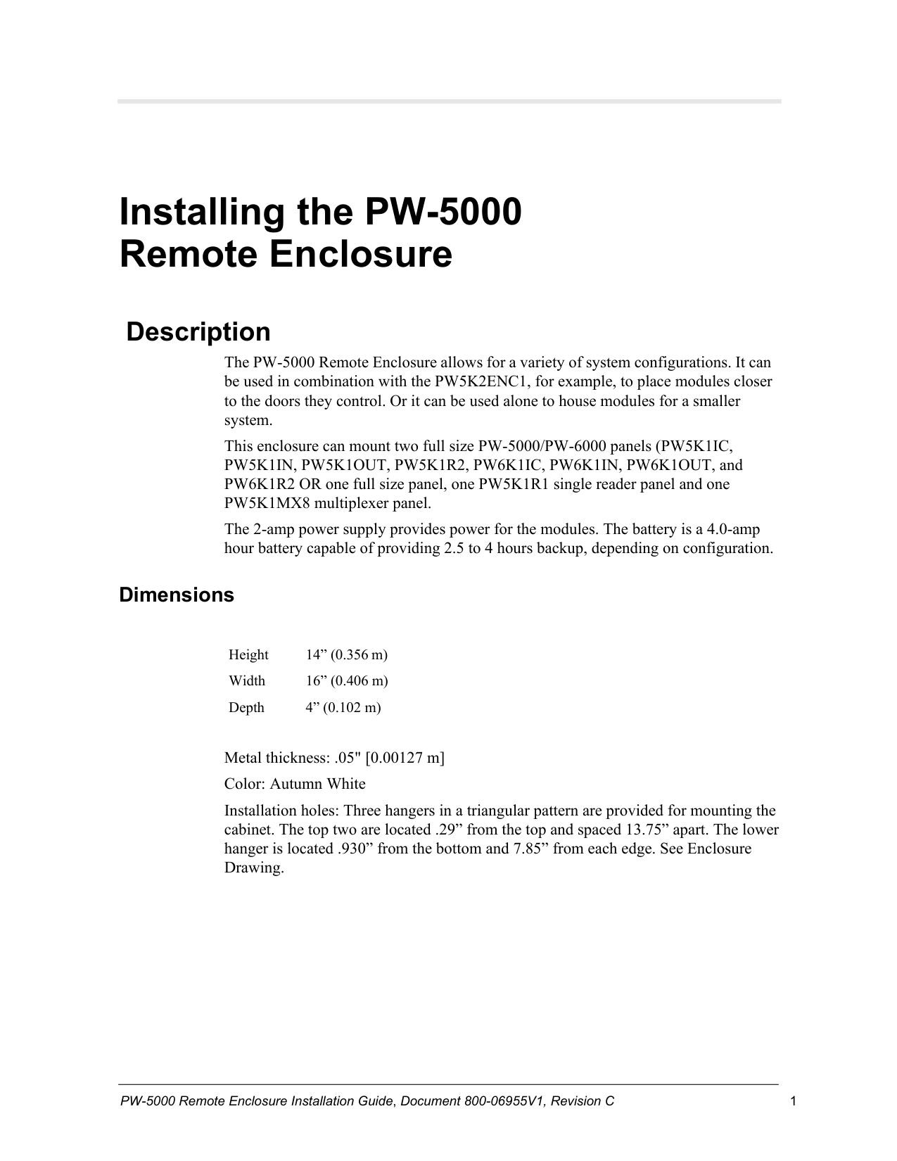
Description The PW-5000 Remote Enclosure allows for a variety of system configurations. It can be used in combination with the PW5K2ENC1, for example, to place modules closer to the doors they control. Or it can be used alone to house modules for a smaller system. This enclosure can mount two full size PW-5000/PW-6000 panels (PW5K1IC, PW5K1IN, PW5K1OUT, PW5K1R2, PW6K1IC, PW6K1IN, PW6K1OUT, and PW6K1R2 OR one full size panel, one PW5K1R1 single reader panel and one PW5K1MX8 multiplexer panel. The 2-amp power supply provides power for the modules. The battery is a 4.0-amp hour battery capable of providing 2.5 to 4 hours backup, depending on configuration.
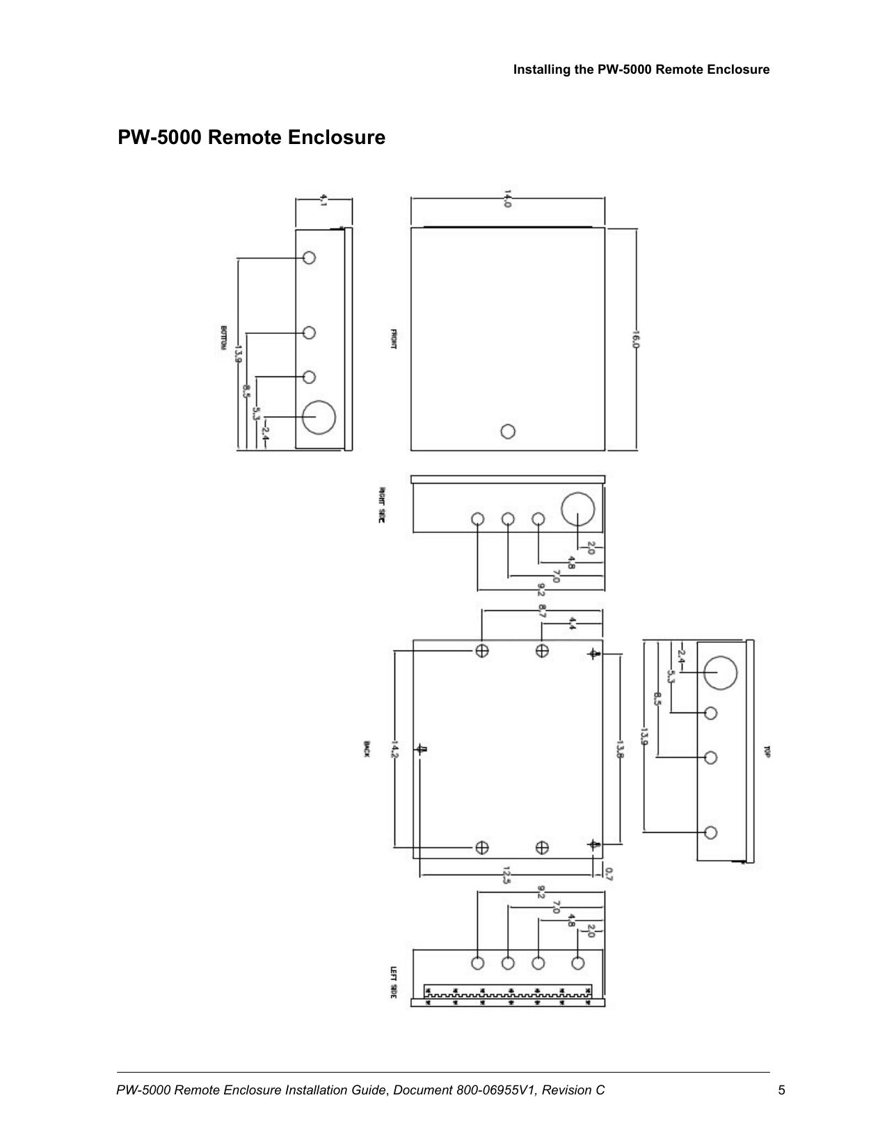
Dimensions
Height 14” (0.356 m) Width 16” (0.406 m) Depth 4” (0.102 m)
Metal thickness: .05" [0.00127 m] Color: Autumn White Installation holes: Three hangers in a triangular pattern are provided for mounting the cabinet. The top two are located .29” from the top and spaced 13.75” apart. The lower hanger is located .930” from the bottom and 7.85” from each edge. See Enclosure Drawing.
Installing the PW-5000 Remote Enclosure Description 2 www.honeywell.com
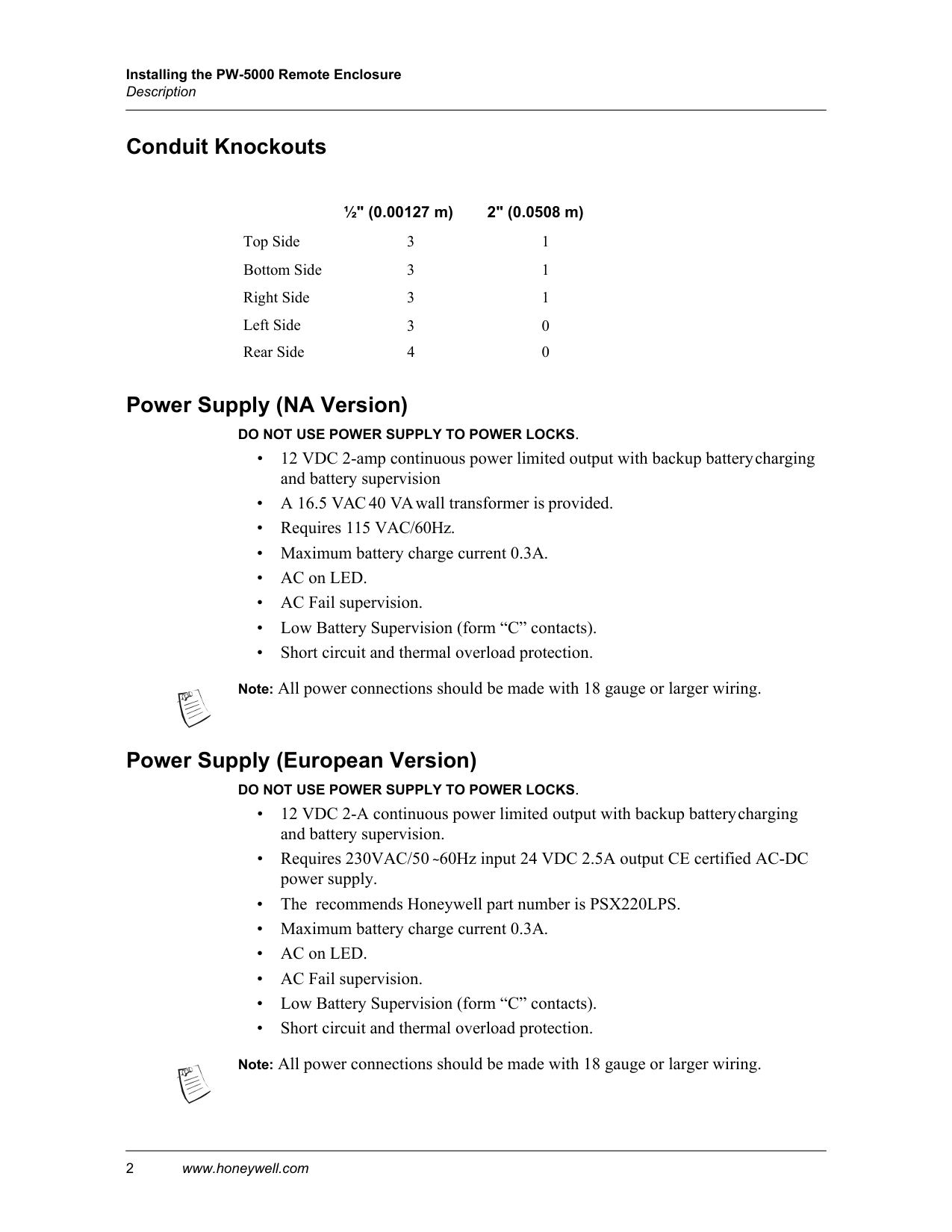
Conduit Knockouts ½" (0.00127 m) 2" (0.0508 m) Top Side 3 1 Bottom Side 3 1 Right Side 3 1 Left Side 3 0 Rear Side 4 0
Power Supply (NA Version)
Do Not Use Power Supply To Power Locks.
Power Supply (European Version)
Do Not Use Power Supply To Power Locks.
Installing the PW-5000 Remote Enclosure PW-5000 Remote Enclosure Installation Guide, Document 800-06955V1, Revision C 3
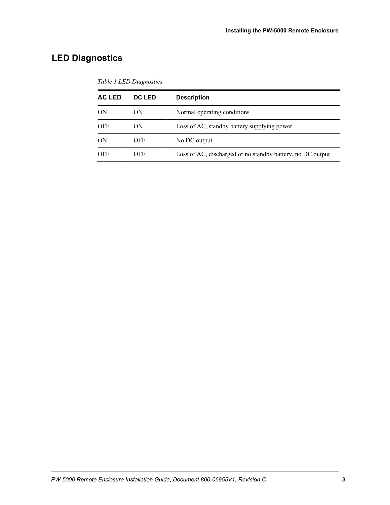
LED Diagnostics
Table 1 LED Diagnostics
Ac Led
Dc Led
DescriptionOn
On
Normal operating conditionsOff
On
Loss of AC, standby battery supplying powerOn
Off
No DC outputOff
Off
Loss of AC, discharged or no standby battery, no DC output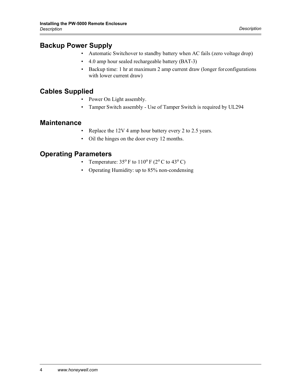
Installing the PW-5000 Remote Enclosure Description 4 www.honeywell.com
Description
Backup Power Supply
Cables Supplied
Maintenance
Operating Parameters
Installing the PW-5000 Remote Enclosure PW-5000 Remote Enclosure Installation Guide, Document 800-06955V1, Revision C 5
PW-5000 Remote Enclosure
Installing the PW-5000 Remote Enclosure Description 6 www.honeywell.com
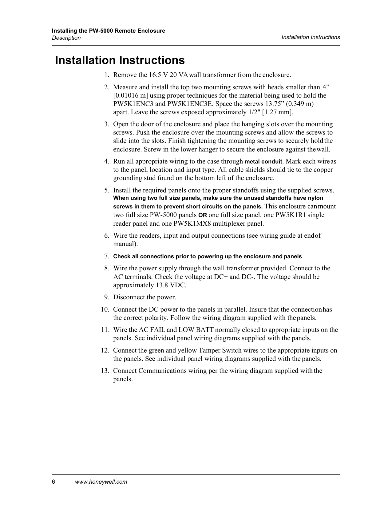
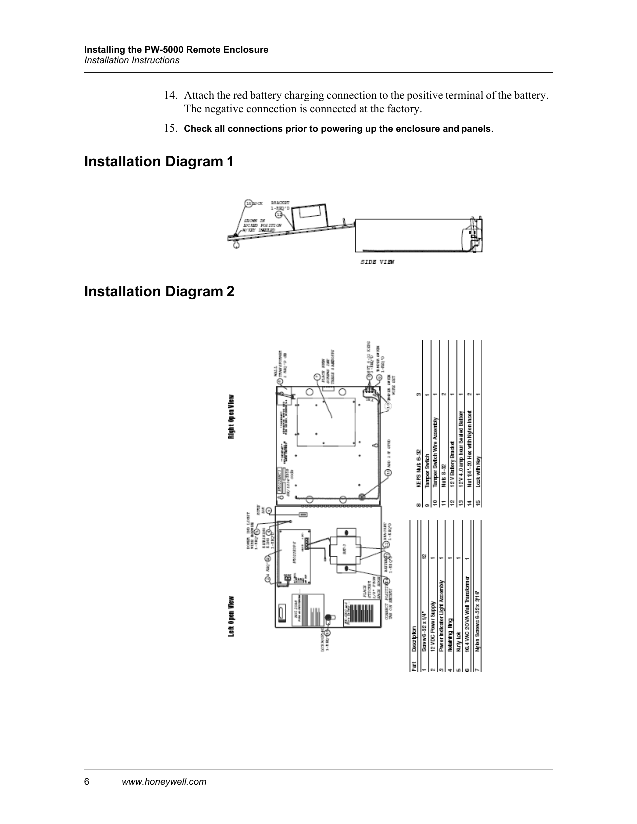
Installation Instructions
Installation Instructions
Installing the PW-5000 Remote Enclosure 6 www.honeywell.com
Installation Instructions
Installation Diagram 1
Installation Diagram 2
Installing the PW-5000 Remote Enclosure Cable Specifications PW-5000 Remote Enclosure Installation Guide, Document 800-06955V1, Revision C 7
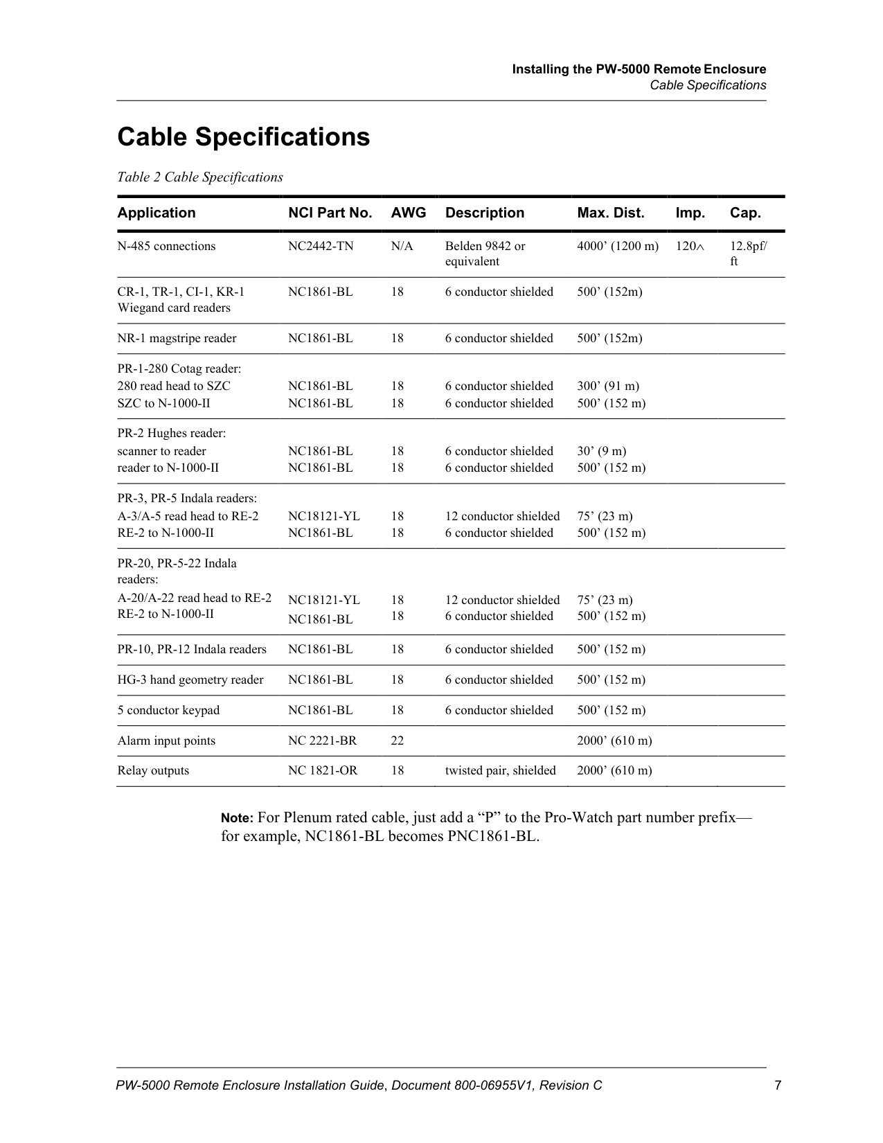
Cable Specifications
Table 2 Cable Specifications
Application NCI Part No.
Awg
Description Max. Dist. Imp. Cap. N-485 connectionsNc2442-Tn
N/A
Belden 9842 or equivalent 4000’ (1200 m) 120∧ 12.8pf/ ftCr-1, Tr-1, Ci-1, Kr-1
Wiegand card readersNc1861-Bl
18 6 conductor shielded 500’ (152m) NR-1 magstripe readerNc1861-Bl
18 6 conductor shielded 500’ (152m) PR-1-280 Cotag reader: 280 read head to SZCNc1861-Bl
18 6 conductor shielded 300’ (91 m) SZC to N-1000-IINc1861-Bl
18 6 conductor shielded 500’ (152 m) PR-2 Hughes reader: scanner to readerNc1861-Bl
18 6 conductor shielded 30’ (9 m) reader to N-1000-IINc1861-Bl
18 6 conductor shielded 500’ (152 m) PR-3, PR-5 Indala readers: A-3/A-5 read head to RE-2Nc18121-Yl
18 12 conductor shielded 75’ (23 m) RE-2 to N-1000-IINc1861-Bl
18 6 conductor shielded 500’ (152 m) PR-20, PR-5-22 Indala readers: A-20/A-22 read head to RE-2Nc18121-Yl
18 12 conductor shielded 75’ (23 m) RE-2 to N-1000-IINc1861-Bl
18 6 conductor shielded 500’ (152 m) PR-10, PR-12 Indala readersNc1861-Bl
18 6 conductor shielded 500’ (152 m) HG-3 hand geometry readerNc1861-Bl
18 6 conductor shielded 500’ (152 m) 5 conductor keypadNc1861-Bl
18 6 conductor shielded 500’ (152 m) Alarm input pointsNc 2221-Br
22 2000’ (610 m) Relay outputsNc 1821-Or
18 twisted pair, shielded 2000’ (610 m)Note: For Plenum rated cable, just add a “P” to the Pro-Watch part number prefix— for example, NC1861-BL becomes PNC1861-BL.
Installing the PW-5000 Remote Enclosure 8 www.honeywell.com
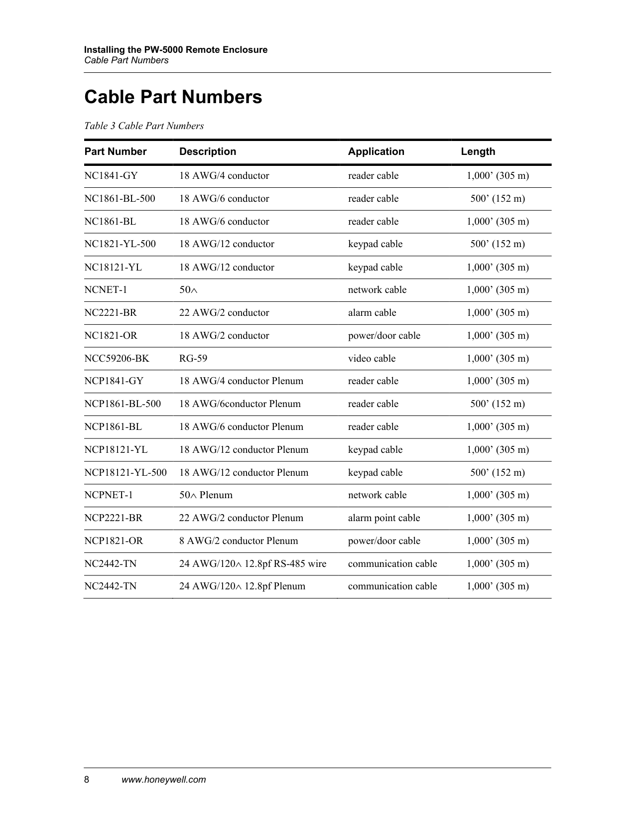
Cable Part Numbers
Cable Part Numbers Table 3 Cable Part Numbers
Part Number Description Application Length
Nc1841-Gy
18 AWG/4 conductor reader cable 1,000’ (305 m)Nc1861-Bl-500
18 AWG/6 conductor reader cable 500’ (152 m)Nc1861-Bl
18 AWG/6 conductor reader cable 1,000’ (305 m)Nc1821-Yl-500
18 AWG/12 conductor keypad cable 500’ (152 m)Nc18121-Yl
18 AWG/12 conductor keypad cable 1,000’ (305 m)Ncnet-1
50∧ network cable 1,000’ (305 m)Nc2221-Br
22 AWG/2 conductor alarm cable 1,000’ (305 m)Nc1821-Or
18 AWG/2 conductor power/door cable 1,000’ (305 m)Ncc59206-Bk
Rg-59
video cable 1,000’ (305 m)Ncp1841-Gy
18 AWG/4 conductor Plenum reader cable 1,000’ (305 m)Ncp1861-Bl-500
18 AWG/6conductor Plenum reader cable 500’ (152 m)Ncp1861-Bl
18 AWG/6 conductor Plenum reader cable 1,000’ (305 m)Ncp18121-Yl
18 AWG/12 conductor Plenum keypad cable 1,000’ (305 m)Ncp18121-Yl-500
18 AWG/12 conductor Plenum keypad cable 500’ (152 m)Ncpnet-1
50∧ Plenum network cable 1,000’ (305 m)Ncp2221-Br
22 AWG/2 conductor Plenum alarm point cable 1,000’ (305 m)Ncp1821-Or
8 AWG/2 conductor Plenum power/door cable 1,000’ (305 m)Nc2442-Tn
24 AWG/120∧ 12.8pf RS-485 wire communication cable 1,000’ (305 m)Nc2442-Tn
24 AWG/120∧ 12.8pf Plenum communication cable 1,000’ (305 m)
Honeywell Integrated Security 135 W. Forest Hill Avenue Oak Creek, WI 53154 United States 800-323-4576 414-766-1798 Fax www.honeywellintegrated.com
Specifications subject to change without notice.
© 2021 Honeywell International Inc. Document 800-06955V1, Revision C