
Ask AI
— answers from the official manualAnswers from the official manual.
Common questions
Common Questions
33 totalWhat does it mean when 'Cool On' or 'Heat On' is flashing on the screen?
A flashing 'Cool On' or 'Heat On' message means the built-in compressor protection feature is engaged. The thermostat forces the compressor to wait a few minutes before restarting to prevent damage to the heating or cooling system. This message is also displayed during a startup delay if AC power loss occurs. Once the wait period is over, the compressor will turn back on automatically. (Page 9)
What are the alert codes and what do they mean?
The thermostat displays 3-digit alert codes when an issue is detected. For example, code 164 means the heat pump needs service, code 173 indicates a thermostat temperature sensor error, and code 399 means the internet connection has been lost. To view an active alert, touch Menu on the home screen, then touch Select to see the alert code and a scrolling description of the required action. (Pages 27–28)
How do I reset the thermostat's schedule back to the default settings?
To reset to the default Monday–Friday, Saturday–Sunday schedule, touch Menu on the thermostat screen, then use the arrows to navigate to RESET and touch Select. Use the arrows to select SCHEDULE and touch Select, then touch Yes to confirm. This will revert the schedule to the factory default without affecting other settings. (Page 18)
What temperature ranges can I set on the Lyric T6 Pro thermostat?
The adjustable heat temperature range is 40–90 °F (4.5–32.0 °C), and the adjustable cool temperature range is 50–99 °F (10.0–37.0 °C). If the temperature setting doesn't change, verify that your desired set point is within these operating ranges. The thermostat's temperature sensor accuracy is ±1.5 °F at 70 °F (0.85 °C at 21.0 °C). (Pages 29–30)
What is the warranty period for the Honeywell Lyric T6 Pro thermostat?
Honeywell warrants the Lyric T6 Pro thermostat to be free from defects in workmanship or materials under normal use and service for a period of five (5) years from the date of purchase. If the product is defective or malfunctions during this period, Honeywell will repair or replace it at their option. This warranty does not cover removal or reinstallation costs. (Page 34)
What should I do if the thermostat screen is blank?
Check the circuit breaker and reset it if necessary. Also make sure the power switch at the heating and cooling system is on and that the furnace door is closed securely. (Page 18)
Show 27 more questions
What does the 'Wait' message on the display mean?
Is a C wire (common wire) required to install the TH6320WF2003?
What does Alert 173 mean and what should I do about it?
How do I perform a factory reset on the TH6320WF2003 thermostat?
What does Alert 168 (Wi-Fi Radio Error) mean and how do I fix it?
How do I reset the air filter reminder after replacing the filter?
What are the temperature range specifications for heating and cooling on this thermostat?
What does the 'Wait' message on the thermostat display mean?
What wiring is required for this thermostat to work — does it need a C wire?
What do I do if the thermostat screen is blank?
How do I run a system test to verify heating and cooling are working correctly?
What power requirements does the Th6320Wf2003 thermostat need?
How do I mount the UWP mounting system?
What does error code 168 (Wi-Fi Radio Error) mean?
How do I perform a system test on the thermostat?
What does alert 177 (Indoor Temperature Sensor Error) indicate?
How do I set the R and U slider tabs on the UWP?
What should I do if the screen is blank?
How do I access Contractor Mode in the Lyric app?
What is the operating temperature range for the thermostat?
What does alert 181 (Replace Air Filter) mean and how do I reset it?
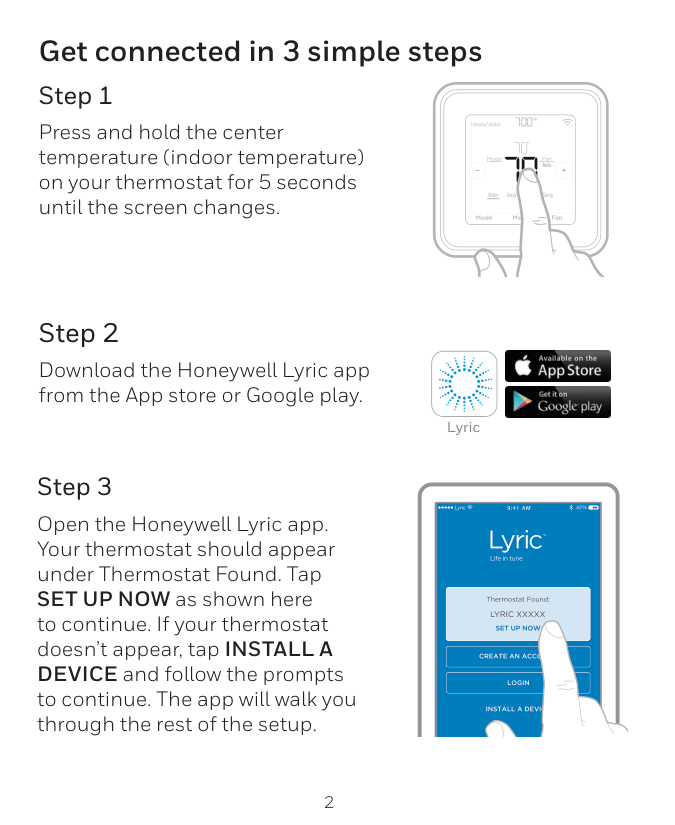
How do I connect my Lyric T6 Pro Wi-Fi thermostat to my home Wi-Fi network?
How do I lock the thermostat screen to prevent unauthorized changes?
How do I safely clean the thermostat screen?
What is Adaptive Intelligent Recovery and how do I enable or disable it?
How do I test the heating and cooling system after installation?
How do I lock the thermostat screen so users cannot change settings?
Full Manual
20 pages
Package Includes:
Phone 1-800-633-3991
2
UWP Mounting System installation
3
Terminal designations Conventional Systems Heat pump systems Terminal Description Terminal Description
S/S
Universal input for a wired indoor, outdoor sensorS/S
Universal input for a wired indoor, outdoor sensorY
Compressor Stage 1Y
Compressor Stage 1Y2
Compressor Stage 2Y2
Compressor Stage 2G
Fan RelayG
Fan RelayC
24VAC Common wire from secondary side of cooling transformer (if 2 transformers)C
24VAC Common wire from secondary side of cooling transformerK*
Connect to K on Wire Saver ModuleK*
Connect to K on Wire Saver ModuleU/U**
Universal relay for ventilationU/U**
Universal relay for ventilationA
L/A
Connect to compressor monitorW
Heat Stage 1O/B
Changeover valve for heat pumpsW2
Heat Stage 2 Aux Backup HeatE
Emergency HeatR
24 VAC Heating transformerR
24 VAC Heating transformer Rc 24 VAC Cooling transformer Rc 24 VAC Cooling transformer
4
Setting Slider Tabs Set R Slider Tab, see Figure 9.
5
Wiring 1H/1C System (1 transformer)
R
Power Rc [R+Rc joined by Slider Tab]Y
Compressor contactorC
24VAC commonW
Heat relayG
Fan relayNotes:
1 Available wiring configurations differ by product models/product numbers. 2 Use 18- to 22- gauge thermostat wire. Shielded cable is not required. 3 Set the R Slider Tab on the UWP to the up position (1 wire) for 1 transformer systems or the down position (2 wires) for 2 transformer systems. See "Setting Slider Tabs" on page 4. 4 Set the U Slider Tab to the up position (1 wire) for non-powered ventilation or the down position (2 wires) for powered ventilation. See "Setting Slider Tabs" on pageR
Power (heating transformer) Rc Power (cooling transformer)Y
Compressor contactorC
24 VAC common from cooling transformerW
Heat relayG
Fan relay 2H/2C System (1 transformer)R
Power Rc [R+Rc joined by Slider Tab]Y
Compressor contactor (stage 1)C
24VAC commonW
Heat relay (stage 1)G
Fan relay W2 Heat relay (stage 2)Y2
Compressor contactor (stage 2) Hot Water Relay PanelR
Power Rc [R+Rc joined by Slider Tab]W
Heat RelayC
24VAC common Heat-only System with FanR
Power Rc [R+Rc joined by Slider Tab]C
24VAC commonW
Heat relayG
Fan relay Cool-only System with FanR
Power Rc [R+Rc joined by Slider Tab]Y
Compressor contactorC
24VAC commonG
Fan relay NOTE: If the panel does not provide 24 volts AC at R and C, set the slider to down position and wire a separate transformer to Rc and C.
6
Heat pumps systems 1H/1C Heat Pump System
R
Power Rc [R+Rc joined by Slider Tab]Y
Compressor contactorC
24VAC common O/B Changeover valveG
Fan relay 2H/1C Heat Pump SystemR
Power Rc [R+Rc joined by Slider Tab]Y
Compressor contactorC
24VAC common O/B Changeover valveG
Fan relay Aux Auxiliary heatE
Emergency heat relayL
Heat pump fault input 2H/2C Heat Pump SystemR
Power Rc [R+Rc joined by Slider Tab]Y
Compressor contactor (stage 1)C
24VAC common O/B Changeover valveG
Fan relayY2
Compressor contactor (stage 2)L
Heat pump fault input 3H/2C Heat Pump SystemR
Power Rc [R+Rc joined by Slider Tab]Y
Compressor contactor (stage 1)C
24VAC common O/B Changeover valveG
Fan relay Aux Auxiliary heatE
Emergency heat relayY2
Compressor contactor (stage 2)L
Heat pump fault input NOTE: This application is not supported by all models of the thermostat.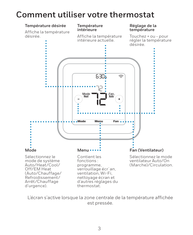
7
Ventilation systems NOTE: Ventilation is not available on all models. Mounting thermostat 1 Push excess wire back into the wall opening. 2 Close the UWP door. It should remain closed without bulging. 3 Align the UWP with the thermostat, and push gently until the thermostat snaps in place. 4 If needed, gently pull to remove the thermostat from the UWP Using U Slider Tab Wired to ERV/HRV whole house ventilator with internal power supply. Wired to fresh air damper powered by furnace transformer. 11 12

8
Installer setup – using the thermostat Setup using the thermostat
Notes:
Isu #
ISU option blinking Cancels ISU option selection, go back to view ISU Arrow buttons used to scroll through ISU options Saves selected ISU option moves on to the next ISU screen Edit View ISUIsu #
ISU name and option (scrolling) Arrow buttons used to scroll through ISUs No Yes Select
9
Advanced menu options Device Setup This is used to access the device ISU setting. Screen Lock The thermostat touch screen can be set to lock fully or partially. Rater View A read only place to view all the ventilation settings. System Test Test the heating and cooling system. Range Stop (Temperature) Set the minimum, maximum, cool and heat temperature set points. Installer setup – using the Lyric app Setup using the Lyric app Download the Lyric app from App Store or Google Play to use a hidden PRO installation feature that will allow you to configure the thermostat and personally invite your customer to connect to the installed thermostat at the same time. Enter Contractor Mode To enter Contractor Mode, press and hold the Lyric logo for 5 seconds. Then tap Confirm to begin using Contractor Mode. Follow steps to personally invite your customer to connect their Lyric App. Lyric Installer setup – advanced menu To access the advanced menu, press and hold the Menu button for 5 seconds. Touch or to go through the options in the advanced menu.
Am
Menu Fan Mode Fan Auto Mode Heat Wake Away Home Sleep Following Schedule Reset Access all reset options on the thermostat. This is the only place to access factory reset.
10
Auto Chg. On
Am
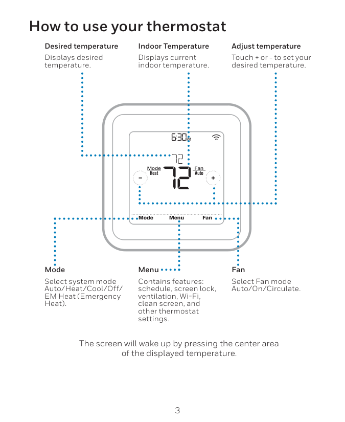
Heat On Menu Fan Mode Fan Auto Mode Heat Wake Away Home Sleep Following Schedule Recovery Key features The screen will wake up by pressing the center area of the displayed temperature. The screen will stay lit for 45 seconds. Brightness can be adjusted in the Menu. System status information Cool On, Heat On Emergency Heat On, Recovery, or Auto Changeover On. Schedule information Following time-based or location-based temperature control. Desired Temperature Displays the current desired temperature setting. Indoor Temperature Displays the current indoor temperature. Mode Select system mode: Auto/Heat/Cool/Off/EM Heat (Emergency Heat). Connection status information Status of Wi-Fi Connection: Connected, Disconnected, or Wi-Fi is Off. Messaging Shows device setup options, menu options, reminders, schedule overrides. Schedule period Shows schedule period: Wake/Away/Home/ Sleep. Fan Select Fan mode Auto/ On/Circulate. Time, ISU #, or Alert # Menu Touch to display options. Start here to set a program schedule. Note: Long press of Menu button for 5 seconds to access Advanced Menu options.
11
Installer setup options (ISU) – advanced menu
# Isu
ISU Name ISU Options (defaults in bold) Notes 120 Schedule Type No Schedule MO-SU = Every day the same MO-FR, SA, SU = 5-1-1 schedule MO-FR, SA-SU = 5-2 schedule Each Day = Every day individual You can change default MO-FR, SA-SU schedule here. To edit periods during days, temperature setpoints, or to turn Schedule On/Off, from the home screen, go to MENU/SCHEDULE. 125 Temp Scale Fahrenheit, Celsius 130 Outdoor Temp No, Wired, Internet Select outdoor temperature data source. This ISU automatically defaults to Internet when registered to Lyric app and no wired outdoor sensor is selected. We recommend using a wired outdoor sensor connected to the “S” terminals on the UWP. (See "Wiring" on page 5.) An outdoor temperature is required to set the following ISUs: ISU 355 Compressor Lockout, ISU 356 Aux Heat Lockout, ISU 1013 Low Outdoor Temperature Ventilation Lockout, ISU 1014 High Outdoor Temperature Ventilation Lockout, and ISU 1015 High Outdoor Dew Point Ventilation Lockout. 200 System Type Conventional Forced Air Heat Pump Boiler Cool Only Basic selection of system your thermostat will control. 205 Equipment Type Conventional Forced Air Heat: Standard Gas (STD GAS), High Efficiency Gas (EFF GAS), Oil, Electric, Fan Coil Heat Pump: Air To Air, Geothermal Boiler: Hot Water, Steam This option selects the equipment type your thermostat will control. Note: This option is NOT displayed if ISU 200 is set to Cool Only. 218 Reversing Valve 0/B on Cool, 0/B on Heat This ISU is only displayed if ISU 200 is set to Heat Pump. Select whether reversing valve O/B should energize on cool or on heat 220 Cool Stages (#200=Conv./200=Hp)
0, 1, 2 221 Heat Stages/Aux/E Stages (#200=Conv./200=Hp)
Heat Stages: 0, 1, 2 AUX/E Stages: 0, 1 Maximum of 2 Heat Stages for conventional systems. Maximum of 1 Aux/E stages for heat pump systems. 230 Fan Control Equipment, Thermostat This ISU is only displayed if ISU 205 is set to Electric Forced Air or Fan Coil. 253 Aux/E Control Both Aux/E, Either Aux/E Set “EITHER AUX/E” if you want to setup and control Auxiliary and Emergency heating separately . This ISU is only displayed if ISU 200 is set to Heat Pump AND if ISU 221 Aux/E stages = 1. 255 Aux Heat Type Electric, Gas/Oil (or Fossil Forced Air) This ISU is displayed only if ISU 200 is set to heat pump AND if ISU 221 Aux/E heat stages = 1. Note: Options of this ISU may vary depending on the model of the thermostat. Note: ISU options available may vary upon the thermostat model and equipment setup. Table 1.
12
Installer setup options (ISU)– advanced menu
# Isu
ISU Name ISU Options (defaults in bold) Notes 256 EM Heat Type Electric, Gas/Oil (or Fossil Forced Air) This ISU is displayed only if ISU 200 is set to Heat Pump AND if ISU 221 Aux/E heat stages = 1 AND if ISU 253 is set to run AUX/E heat separately. Note: This ISU may not be available at all on some models. 260 Fossil Kit Control Thermostat, External (Fossil Fuel Kit Controls Backup Heat) This ISU is displayed only if ISU 200 is set to Heat Pump AND if ISU 221 Aux/E heat stages = 1, AND if ISU 256 is set to Gas/Oil. Note: This ISU may not be available at all on some models. 300 Auto Changeover On, Off OFF: The user must select heating or cooling as needed to maintain the desired indoor temperature. ON (Automatic): On (enabled) Allows user to select Auto Changeover as one of the system modes from the home screen. In auto mode, the thermostat can control either heating or cooling to maintain the desired indoor temperature. 303 Auto Differential 0 °F to 5 °F or 0.0 °C to 2.5 °C Differential is the minimum number of degrees allowed between the heat and cool setpoints when the thermo stat is in auto-changeover. Differential is NOT deadband. The deadband temperature between when heating (or cooling) cycles on and cycles off to maintain setpoint is not adjustable. Honeywell uses an algorithm that fixes deadband at 0 °F. This algorithm is more advanced than on previous thermostats. 305 High Cool Stage Finish Yes, No This ISU is only displayed when the thermostat is set to 2 cool stages. When set to YES, this feature keeps the higher stage of the cooling equipment running until the desired setpoint is reached. 306 High Heat Stage Finish Yes, No This ISU is only displayed when the thermostat is set to 2 or more heat stages. When set to YES, this feature keeps the higher stage of the heating equipment running until the desired setpoint is reached. 340 Aux Heat Droop 0 = Comfort; 2 °F to 15 °F from setpoint (in 1 °F incre ments) or 1.0 °C to 7.5 °C from setpoint (in 0.5 °C increments) Aux heat droop can be set on heat pump systems with an auxiliary heat stage. The Comfort setting is NOT available for Dual Fuel systems. Default setting is 0 °F (Comfort) for Electric while 2 °F for Gas/Oil. The indoor temperature must drop to the selected droop setting before the thermostat will turn Aux Heat on. For example, if Aux Heat is set to 2 °F (1.0 °C), the indoor temperature must be 2 ° F (1.0 ° C) away from the setpoint before Aux Heat turns on. When set to Comfort, the thermostat will use Aux Heat as needed to keep the indoor tem perature within 1 °F (0.5 ° C) degree of the setpoint. 350 Up Stage Timer Aux Heat Off, 30, 45, 60, 75, 90 minutes 2, 3, 4, 5, 6, 8, 10, 12, 14, 16 hours The Auxiliary Heat Upstage Timer starts when the highest stage of the previous heating equipment type turns on. Auxiliary heat will be used (if needed) when the timer expires. This ISU is only displayed when ISU 340 (AUX Heat Droop) is set to 2 °F or higher. 355 Balance Point (Compressor Lockout) Off, 5 °F to 60 °F (in 5 °F increments) or -15.0 °C to 15.5 °C (in 2.5 °C or 3.0 °C increments) Compressor Lockout requires an outdoor temperature. Set Compressor Lockout to the temperature below which it is inefficient to run the heat pump. When outside temperature is below this setting, thermostat will lockout heat pump and run Aux Heat only. This ISU is only displayed if ISU 130 = Wired or Internet, ISU 200 is set to Heat Pump, ISU 221 Aux/E stages = 1, AND ISU 260 is set to Thermostat. We recommend using a wired remote sensor as an outdoor temperature source. Default is 40 °F if ISU 205 Heating Equipment is Air to Air Heat Pump and ISU 255 Aux Heat Type is Gas/Oil. Default is Off if ISU 205 Heating Equipment is Air to Air Heat Pump and ISU 255 Aux Heat Type is Electric. Default is Off if ISU 205 Heating Equipment is Geothermal. Compressor Lockout is optional for any type of heat pump (Air to Air Heat Pump, Geothermal Heat Pump). Table 2.
13
Installer setup options (ISU)– advanced menu
# Isu
ISU Name ISU Options (defaults in bold) Notes 356 Aux Heat Lock Out (Aux Heat Outdoor Lockout) Off, 5 °F to 65 °F (in 5 °F increments) or -15.0 °C to 18.5 °C (in 2.5 °C or 3.0 °C increments) Aux Heat Lockout requires an outdoor temperature. Set Aux Heat Lockout to optimize energy bills and to not allow it to run the more expensive Aux Heat source above certain outdoor temperature limit. This ISU is only displayed if ISU 200 is set to Heat Pump, AND ISU 260 is set to Thermostat control AND if ISU 221 Aux/E stages = 1. 365 Cool 1 CPH (Cooling cycle rate stage 1)1 - 6 Cph (3 Cph)
This ISU is only displayed when Cool /Compressor Stages is set to 1 or more stages. Cycle rate limits the maxi mum number of times the system can cycle in a 1 hour period measured at a 50% load. For example, when set to 3 CPH, at a 50% load, the most the system will cycle is 3 times per hour (10 minutes on, 10 minutes off). The system cycles less often when load conditions are less than or greater than a 50% load. 366 Cool 2 CPH (Cooling cycle rate stage 2)1 - 6 Cph (3 Cph)
This ISU is only displayed when Cool /Compressor Stages is set to 2. 370 Heat 1 CPH (Heating cycle rate stage 1)1 - 12 Cph
This ISU is only displayed when Heat Stages is set to 1 stage or more stages. Cycle rate limits the maximum number of times the system can cycle in a 1 hour period measured at a 50% load. For example, when set to 3 CPH, at a 50% load, the most the system will cycle is 3 times per hour (10 minutes on, 10 minutes off). The system cycles less often when load conditions are less than or greater than a 50% load. The recommended (default) cycle rate settings are below for each heating equipment type: Standard Efficiency Gas Forced Air = 5 CPH; High Efficiency Gas Forced Air = 3 CPH; Oil Forced Air = 5 CPH; Electric Forced Air = 9 CPH; Fan Coil = 3 CPH; Hot Water Radiant Heat = 3 CPH; Steam = 1 CPH. 371 Heat 2 CPH (Heating cycle rate stage 2)1 - 12 Cph
This ISU is only displayed when Heat Stages is set to 2 stages. The recommended (default) cycle rate settings are below for each heating equipment type: Standard Efficiency Gas Forced Air = 5 CPH; High Efficiency Gas Forced Air = 3 CPH; Oil Forced Air = 5 CPH; Electric Forced Air = 9 CPH; Fan Coil = 3 CPH; Hot Water Radiant Heat = 3 CPH; Steam = 1 CPH. 375 Aux Heat CPH (Heating cycle rate Auxiliary Heat)1 - 12 Cph
This ISU is only displayed when ISU 200 = Heat Pump and ISU 221=1. It is only displayed when Auxiliary Heat is configured. The recommended cycle rate settings are below for each heating equipment type: Standard Efficiency Gas Forced Air = 5 CPH; High Efficiency Gas Forced Air = 3 CPH; Oil Forced Air = 5 CPH; Electric Forced Air = 9 CPH. 378 EM Heat CPH (Heating cycle rate Emergency Heat)1 - 12 Cph
This ISU is only displayed when Emergency Heat is configured and ISU 253: Aux/E Terminal Control is set to control Aux and E heat Independently. The recommended cycle rate settings are below for each heating equip ment type: Standard Efficiency Gas Forced Air = 5 CPH; High Efficiency Gas Forced Air = 3 CPH; Oil Forced Air = 5 CPH; Electric Forced Air = 9 CPH. 387 Compressor Protection Off, 1 - 5 minutes The thermostat has a built in compressor protection (minimum off timer) that prevents the compressor from restarting too early after a shutdown. The minimum-off timer is activated after the compressor turns off. If there is a call during the minimum-off timer, the thermostat shows “Wait” in the display. This ISU is displayed if ISU 220 is set to at least 1 stage. 390 Ext Fan Run Time in Cool Off, 30, 60, 90 seconds 2, 3, 4, 5, 6, 7, 8, 9, 10, 11, 12, 13, 14, 15 minutes After the call for cooling ends, the thermostat keeps the fan on for the selected amount of time for increased efficiency. This may reintroduce humidity into the living space. This ISU is displayed if ISU 220 is set to at least 1 stage. Table 3.
14
Installer setup options (ISU)– advanced menu
# Isu
ISU Name ISU Options (defaults in bold) Notes 391 Ext Fan Run Time in Heat Off, 30, 60, 90 seconds 2, 3, 4, 5, 6, 7, 8, 9, 10, 11, 12, 13, 14, 15 minutes After the call for heating ends, the thermostat keeps the fan on for the selected amount of time for increased efficiency. This ISU is displayed if ISU 230 is set to Thermostat Controls Fan. 425 Adaptive Recovery On, Off Adaptive Intelligent Recovery (AIR) is a comfort setting. Heating or cooling equipment will turn on earlier, ensuring the indoor temperature will match the setpoint at the scheduled time. 429 Max Cool Temperature from Min. Cool Temp. to 99 °F or to 37.0 °C (90 °F or 32 °C) The user cannot set the cooling temperature above this level. 430 Min Cool Temperature from 50 °F or 10.0 °C to Max. Cool Temp. (50 °F or 10 °C) The user cannot set the cooling temperature below this level. 431 Max Heat Temperature from Min. Heat Temp. to 90 °F or to 32.0 °C (90 °F or 32 °C) The user cannot set the heating temperature above this level. 432 Min Heat Temperature from 40 °F or 4.4 °C to Max. Heat Temp. (50 °F or 10 °C) The user cannot set the heating temperature below this level. 435 Lock Screen None, Partial, Full Unlocked: User has access to all thermostat settings. Partially Locked: User can modify only temperature settings. Fully Locked: User cannot modify any settings. Screen will be locked by default factory code and cannot be changed. This code is displayed for a short time, when you are about to lock the thermostat screen. Please note the code in safe place for future reference. 500 Indoor Sensor Yes, No Set this ISU when you want to wire a remote indoor sensor to the “S” terminals on the UWP - see "Wiring" on page 5. This ISU is only displayed only if ISU 130 is set to NO wired outdoor sensor configured 515 Sensor type 10k, 20k Choose resistance type of wired indoor sensor. This ISU is only displayed when indoor sensor is configured -Isu 500.
520 Temperature Control Thermostat, Wired, Average This ISU is only displayed when indoor sensor is configured - ISU 500. You can choose what temperature source to be used or you can ask thermostat to use both thermostat and remote sensors for higher accuracy of measurement. 702 Air Filters 0 - 2 This ISU refers to the number of air filters in the system. 711 Air Filter 1 Reminder Off 10, 20, 30, 45, 60, 90, 120, 150 Run Time Days 30, 45, 60, 75 Days 3, 4, 5, 6, 9, 12, 15 Months Choose either calendar or equipment run time-based reminder. 712 Air Filter 2 Reminder Off 10, 20, 30, 45, 60, 90, 120, 150 Run Time Days 30, 45, 60, 75 Days 3, 4, 5, 6, 9, 12, 15 Months Choose either calendar or equipment run time-based reminder. 810 Hum Pad Reminder Off 6, 12 Calendar Months 921 Dehum Filter Reminder Off 30, 60 Calendar Days 3 - 12 Calendar Months (in 1 month increments) Table 4.
15
Installer setup options (ISU)– advanced menu
# Isu
ISU Name ISU Options (defaults in bold) Notes 1000 Vent Type None, ERV/HRV, Passive, Fresh Air Damper None: The thermostat does not control ventilation. ERV/HRV: The thermostat controls an Energy Recovery Ventilator or Heat Recovery Ventilator for ventila tion. Passive (Fan Only): The thermostat turns on the fan for ventilation. When set to passive fan, the thermo stat does not control a damper or ventilator. The passive ventilation/passive fan setting only runs the indoor blower fan. This setting does not open a damper or run a ventilator. To use this setting for ventilation, the home would need to be set-up with a pipe from outdoors into the return duct that is either permanently open or has a damper that automatically opens whenever the blower fan is on. Note: Some models only offer the passive fan setting. 1005 Vent Method ASHRAE 2010, ASHRAE 2013, Percent On Time Note: Options of this ISU may vary depending on the model of the thermostat. 1006 Vent Fan Control Thermostat, Equipment Thermostat: The thermostat turns on the ventilation and the fan when ventilation is needed. Equipment: Ventilation equipment controls the blower fan. 1007 Bedrooms 1 - 6 (2) This ISU is only displayed when ISU 1005 Ventilation Method is set to ASHRAE 2010 or 2013. 1008 Home Size 1000 - 5000 Sq. Ft. (1000 Sq. Ft.) This ISU is only displayed when ISU 1005 Ventilation Method is set to ASHRAE 2010 or 2013. 1009 Vent Rate 30 - 350CFM (in 5CFM increments) (150CFM) This ISU is only displayed when ISU 1005 Ventilation Method is set to ASHRAE 2010 or 2013. 1011 Vent Percent On Time 10% - 100% (30%) The thermostat operates ventilation equipment based on a percentage entered in the installer setup (ISU 1012). For example, if Percent on Time is set to 50%, the ventilation equipment will run at random times dur ing a 1 hour period until it reaches a 50% run time (approximately 30 minutes). This ISU is only displayed if ISU 1005 is set to Percent On Time. 1012 Vent Priority Lockouts, ASHRAE Lockouts are Priority: The thermostat places a priority on lockouts versus the ASHRAE ventilation standard. The thermostat will not run ventilation during the following lockout conditions (if configured), unless you manually call for ventilation: Lockout Ventilation during Outdoor Conditions (ISU 1013, 1014 and 1015). Lockout Ventilation during “Sleep” program periods. Note: This option is set by the user on the Ventilation screen in the Menu. ASHRAE is Priority: ASHRAE requires additional ventilation following a long off cycle. The thermostat meets the ASHRAE ventilation standard by running additional ventilation when outdoor conditions are favor able. If ASHRAE cannot be met when outdoor conditions are favorable, the thermostat will override the outdoor lockouts and run ventilation. When using this option, it is recommended that you increase the rate (CFM) of the ventilation equipment to meet the ASHRAE ventilation standard in a shorter run time. The ability to lockout ventilation during the “Sleep” is not an option when you select ASHRAE is Priority. 1013 Low Outdoor Temp Vent Lockout Off, -20 °F to -40 °F (in 5 °F increments) or -28.0 °C to -4.0 °C (in 2.0 °C increments) ISU 130 must be set to Wired or Internet. This ISU is only displayed when ISU 1000 Ventilation Type is set to ERV / HRV or Fresh Air Damper. 1014 High Outdoor Temp Vent Lockout Off, 80 °F to 110 °F (in 5 °F increments) or 26 °C to 44 °C (in 2 °C increments) ISU 130 must be set to Wired or Internet. This ISU is only displayed when ISU 1000 Ventilation Type is set to ERV / HRV or Fresh Air Damper. 1015 High Outdoor Dewpoint Vent Lockout Off, 65 °F to 85 °F (in 5 °F increments) or 18 °C to 30 °C (in 2 °C increments) ISU 130 must be set to Internet. This ISU is only displayed if ISU 1000 Ventilation Type is set to ERV/ HRV or Fresh Air Damper. Table 5.
16
Installer setup options (ISU)– advanced menu
# Isu
ISU Name ISU Options (defaults in bold) Notes 1017 Vent Core Reminder Off, 3, 6, 9, 12 months This ISU is displayed only if ISU 1000 is set to ERV/HRV. 1018 Vent Filter Reminder Off, 3, 6, 9, 12 months 1100 UV Devices 0 - 2 Some systems may have two UV devices, one for the A-Coil and another for Air Treatment. A replacement reminder can be setup for each one separately. 1105 UV Bulb 1 Reminder Off, 6, 12, 24 months 1106 UV Bulb 2 Reminder Off, 6, 12, 24 months 1401 Idle Brightness 0= Off, 0 - 5 Adjust brightness of an inactive backlight (idle screen) from default 0 (backlight off) to 5 (maximum brightness). 1410 Clock Format 12 hour, 24 hour 1415 Daylight Saving On, Off Set to Off in areas that do not follow Daylight Saving Time. 1420 Temp Offset Off, -3 °F to 3 °F (in 1 °F increments) or -1.5 °C to 1.5 °C (in 0.5 °C increments) 0 °F - No difference in displayed temperature and the actual room temperature. The thermostat can display up to 3 °F (1.5 C) lower or higher than the actual measured temperature. Table 6.
17
Performing a system test You can test the system setup in ADVANCED MENU under SYSTEM TEST option. 1 Press and hold Menu on the Lyric thermostat for 5 seconds to access ADVANCED MENU options. 2 Touch or to go to SYSTEM TEST. 3 Touch Select or touch text area. 4 Touch or to select system test type. Touch Select or touch text area. 5 For the heat test and cool test, use or
to activate each stage of the equipment. For the fan test, use or to turn the fan on and off. NOTE: The clock is used as a timer while the stages are running. The Heat On and Cool On indicators are displayed when the system test is running. Viewing equipment status You can see the status of thermostat- controlled equipment in the Menu under the EQMT STATUS option. 1 Touch Menu on your thermostat. 2 Touch or to go to EQMT STATUS. Touch Select or touch text area. 3 Touch or to view statuses of all the equipment the thermostat is controlling. Depending on what feature the thermostat supports or how it was installed, the Equipment Status screen reports data for the following systems:

18
Screen is blank

19
Alerts and reminders Number Alert/Reminder Definition 181 Replace Air Filter (1) Replace air filter (1). Reset the timer by touching the "dismiss" button on thermostat screen after it is replaced. 182 Replace Air Filter (2) Replace air filter (2). Reset the timer by touching the "dismiss" button on thermostat screen after it is replaced. 183 Clean Humidifier Tank and Replace Water Filter Clean humidifier tank and replace the water filter, or contact dealer to do this for you. Reset the timer by touching the “dismiss” button on the thermostat screen after it is replaced. 184 Replace Humidifier Pad Replace humidifier pad. Reset the timer by touching the “dismiss” button on the thermostat screen after it is replaced. 185 Replace Dehumidifier Filter Replace the dehumidifier filter. Reset the timer by touching "dismiss" button on thermostat screen after it is replaced. 186 Clean Ventilator Core Clean ventilator core. Reset the timer by touching the “dismiss” button on thermostat screen after it is replaced. 187 Clean or Replace Ventilator Filter Clean or replace ventilator filter. Reset the timer by touching the “dismiss” button on thermostat screen after it is replaced. 188 Replace UV Bulb (1) Replace UV Bulb (1). Reset the timer by touching the "dismiss" button on thermostat screen after it is replaced. 189 Replace UV Bulb (2) Replace UV Bulb (2). Reset the timer by touching the "dismiss" button on thermostat screen after it is replaced. 210 Register Online For Outdoor Temperature Online registration is required to receive outdoor temperature from the Internet. Outdoor temperature is needed for your current system setup. Download the Lyric app to register your thermostat. 388 Register Online for Remote Access and Outdoor Temperature Online registration is required for remote access and outdoor temperature. Download the Lyric app to register your thermostat. 399 No Internet The connection to the Internet has been lost. Please check your network settings. 400 No Wi-Fi Signal The Wi-Fi signal has been lost. Please wait for the thermostat to reconnect or select a new Wi-Fi network. Follow steps in the Lyric app 508 Wi-Fi Not Configured Please download the Lyric app and follow the steps to connect thermostat to your Wi-Fi network.

Automation and Control Systems Honeywell International Inc. 1985 Douglas Drive North Golden Valley, MN 55422 http://customer.honeywell.com ® U.S. Registered Trademark. © 2016 Honeywell International Inc. 33-00153—07 M.S. Rev. 08-16 Printed in U.S.A.