
Ask AI
— answers from the official manualAnswers from the official manual.
Common questions
Common Questions
29 totalWhat should I do before using the Cen-Tech 61593 Multimeter for the first time?
Before use, read the entire Important Safety Information section at the beginning of the manual. Inspect the multimeter for damage, checking the insulation on connectors and test leads for exposed metal or damaged insulation. Ensure the battery is installed correctly (one 9V battery) and the battery cover is closed before operating the meter.
What does the battery symbol on the LCD display mean?
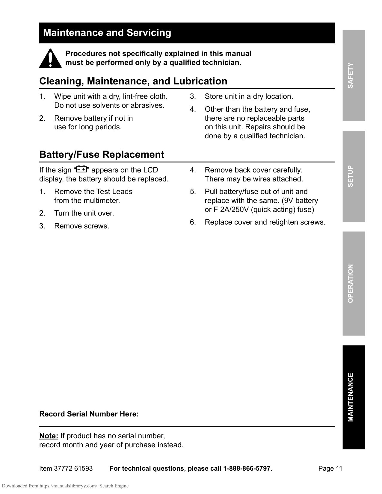
When the battery symbol appears on the LCD display, the battery should be replaced. Remove the test leads, turn the unit over, remove the screws, and carefully remove the back cover. Replace the 9V battery with a new one, then replace the cover and retighten the screws.
How do I measure AC voltage with the 61593?
Turn the Range Selector Switch to 700 ACV, starting with the highest range if voltage is unknown. Plug the red lead into the V/Ω/Hz Jack and the black lead into the COM Jack, then switch the meter ON. Carefully touch the exposed conductors with the probe tips and read the measurement. If the voltage is less than 200 volts, set the selector to a lower range.
What is the maximum voltage and current this meter can safely measure?
The Cen-Tech 61593 can measure up to 1000 VDC or 700 VAC (sine wave). For current measurements, the maximum safe level is 20 amperes continuous, or 20 amperes for 15 seconds maximum on the 20A setting. Do not test voltage on circuits higher than 750 volts AC or 1000 volts DC, or current higher than 20 mA on circuits with higher amperage.
How do I measure resistance with this multimeter?
Turn the Range Selector Switch to the 200Ω position and plug the red lead into the V/Ω/Hz Jack and black lead into the COM Jack. Short the test leads together—the meter should read 0 Ohms. Touch the exposed conductors with the probe tips and read the measurement. If the reading shows '1', switch to the next higher Ohm position. For readings above 1 MΩ, the meter may take a few seconds to stabilize, which is normal.
How do I test capacitors with the 61593?
Turn the Range Selector Switch to the 20μF position, starting with the highest range if capacitance is unknown. WARNING: Fully discharge the capacitor before measuring. Plug the capacitor into the capacitance testing socket (Cx) and switch the meter ON. Read the measurement, and if it's less than 20μF, set the selector to a lower range. Remove the capacitor before switching testing modes.
Show 23 more questions
What are the important safety precautions before measuring resistance or capacitance?
How do I measure current with this multimeter?
How should I store and maintain the Cen-Tech 61593?
How do I test for continuity in a circuit?
What precautions should I take when measuring resistance or testing diodes?
What should I do if I notice abnormal operation of the meter?
What should I do if the battery is low?
How should I store my multimeter when not in use?
Can I test voltages in wet or damp locations?
What is the maximum voltage I can safely test with this multimeter?
Where should I store my multimeter when not in use?
What is the maximum current I can test with this multimeter?
Can I switch between testing modes while the multimeter is connected to a circuit?
How should I properly connect the test leads when using the multimeter?
When should I not use this multimeter?
What battery does the Cen-Tech 61593 multimeter require?
What should I inspect on my multimeter before using it?
Can I apply voltage to the test leads when measuring resistance?
What should I do if parts are missing or broken when I unpack my multimeter?
What type of battery does this multimeter use and how should it be installed?
What inspection should I perform on my multimeter before using it?
Can I test current on high-amperage circuits with this meter?
What voltage levels are safe to test with this multimeter?
Full Manual
12 pages
Visit our website at: http://www.harborfreight.com Email our technical support at: [email protected] REV 14f Owner’s Manual & Safety Instructions Save This Manual Keep this manual for the safety warnings and precautions, assembly, operating, inspection, maintenance and cleaning procedures. Write the product’s serial number in the back of the manual near the assembly diagram (or month and year of purchase if product has no number). Keep this manual and the receipt in a safe and dry place for future reference. When unpacking, make sure that the product is intact and undamaged. If any parts are missing or broken, please call 1-888-866-5797 as soon as possible. Copyright© 2004 by Harbor Freight Tools®. All rights reserved. No portion of this manual or any artwork contained herein may be reproduced in any shape or form without the express written consent of Harbor Freight Tools. Diagrams within this manual may not be drawn proportionally. Due to continuing improvements, actual product may differ slightly from the product described herein. Tools required for assembly and service may not be included. Read this material before using this product. Failure to do so can result in serious injury.
Save This Manual.
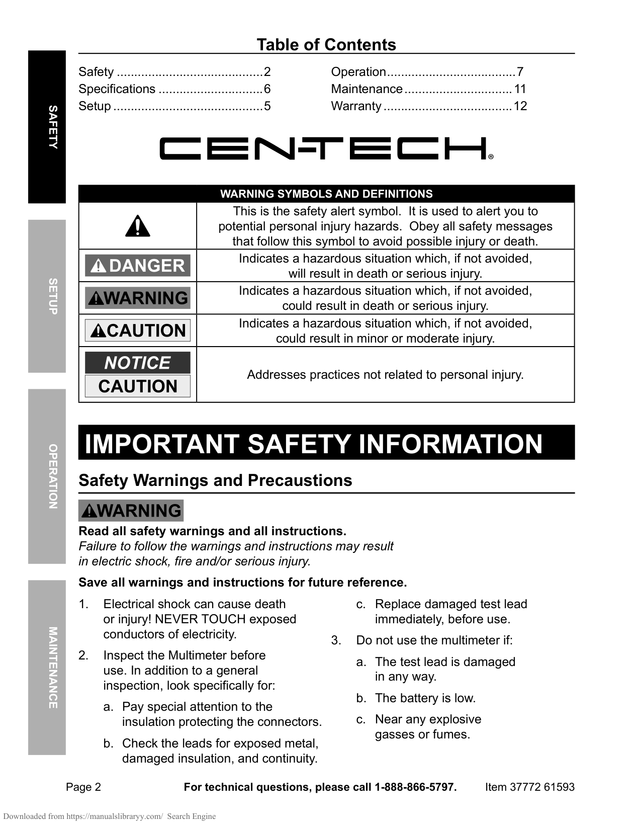
Page 2 For technical questions, please call 1-888-866-5797. Item 37772 61593 Safety Operation Maintenance Setup Table of Contents Safetye������������������������������������������2 Specifications...............................6 Setup............................................5 Operationa�������������������������������������7 Maintenancey�������������������������������11 Warranty......................................12
Warning Symbols And Definitions
This is the safety alert symbol. It is used to alert you to potential personal injury hazards. Obey all safety messages that follow this symbol to avoid possible injury or death. Indicates a hazardous situation which, if not avoided, will result in death or serious injury. Indicates a hazardous situation which, if not avoided, could result in death or serious injury. Indicates a hazardous situation which, if not avoided, could result in minor or moderate injury. Addresses practices not related to personal injury.Important Safety Information
Safety Warnings and Precaustions Read all safety warnings and all instructions. Failure to follow the warnings and instructions may result in electric shock, fire and/or serious injury. Save all warnings and instructions for future reference.
Page 3 For technical questions, please call 1-888-866-5797. Item 37772 61593 Safety Operation Maintenance Setup d. Any abnormal operation is detected. (If in doubt about the condition of the meter, have it serviced.) e. The battery cover is open.
Page 4 For technical questions, please call 1-888-866-5797. Item 37772 61593 Safety Operation Maintenance Setup
Save These Instructions.
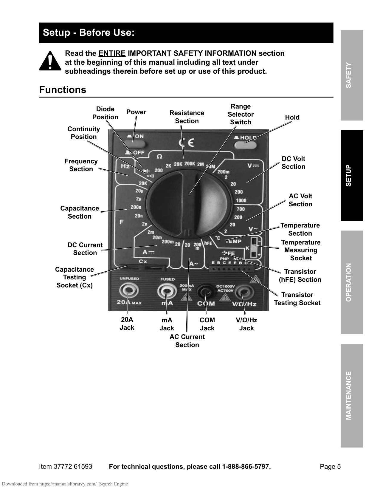
Page 5 For technical questions, please call 1-888-866-5797. Item 37772 61593 Safety Operation Maintenance Setup Setup - Before Use: Read the ENTIRE IMPORTANT SAFETY INFORMATION section at the beginning of this manual including all text under subheadings therein before set up or use of this product. Functions AC Volt Section DC Volt Section AC Current Section DC Current Section Resistance Section V/Ω/Hz Jack
Com
Jack mA Jack20A
Jack Capacitance Section Frequency Section Transistor (hFE) Section Diode Position Continuity Position Temperature Section Temperature Measuring Socket Range Selector Switch Transistor Testing Socket Capacitance Testing Socket (Cx) Power Hold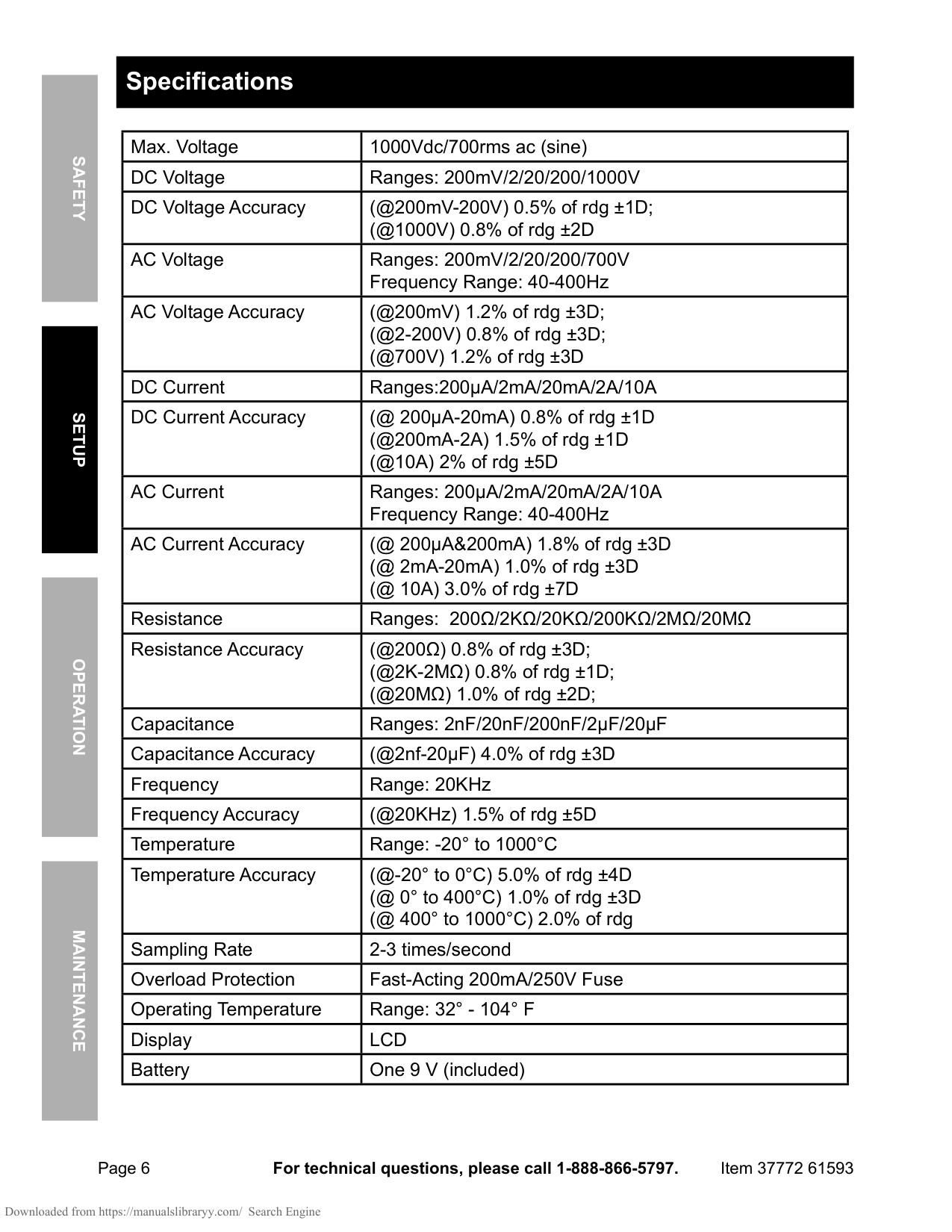
Page 6 For technical questions, please call 1-888-866-5797. Item 37772 61593 Safety Operation Maintenance Setup Specifications Max. Voltage 1000Vdc/700rms ac (sine) DC Voltage Ranges: 200mV/2/20/200/1000V DC Voltage Accuracy (@200mV-200V) 0.5% of rdg ±1D; (@1000V) 0.8% of rdg ±2D AC Voltage Ranges: 200mV/2/20/200/700V Frequency Range: 40-400Hz AC Voltage Accuracy (@200mV) 1.2% of rdg ±3D; (@2-200V) 0.8% of rdg ±3D; (@700V) 1.2% of rdg ±3D DC Current Ranges:200μA/2mA/20mA/2A/10A DC Current Accuracy (@ 200μA-20mA) 0.8% of rdg ±1D (@200mA-2A) 1.5% of rdg ±1D (@10A) 2% of rdg ±5D AC Current Ranges: 200μA/2mA/20mA/2A/10A Frequency Range: 40-400Hz AC Current Accuracy (@ 200μA&200mA) 1.8% of rdg ±3D (@ 2mA-20mA) 1.0% of rdg ±3D (@ 10A) 3.0% of rdg ±7D Resistance Ranges: 200Ω/2KΩ/20KΩ/200KΩ/2MΩ/20MΩ Resistance Accuracy (@200Ω) 0.8% of rdg ±3D; (@2K-2MΩ) 0.8% of rdg ±1D; (@20MΩ) 1.0% of rdg ±2D; Capacitance Ranges: 2nF/20nF/200nF/2μF/20μF Capacitance Accuracy (@2nf-20μF) 4.0% of rdg ±3D Frequency Range: 20KHz Frequency Accuracy (@20KHz) 1.5% of rdg ±5D Temperature Range: -20° to 1000°C Temperature Accuracy (@-20° to 0°C) 5.0% of rdg ±4D (@ 0° to 400°C) 1.0% of rdg ±3D (@ 400° to 1000°C) 2.0% of rdg Sampling Rate 2-3 times/second Overload Protection Fast-Acting 200mA/250V Fuse Operating Temperature Range: 32° - 104° F Display
Lcd
Battery One 9 V (included)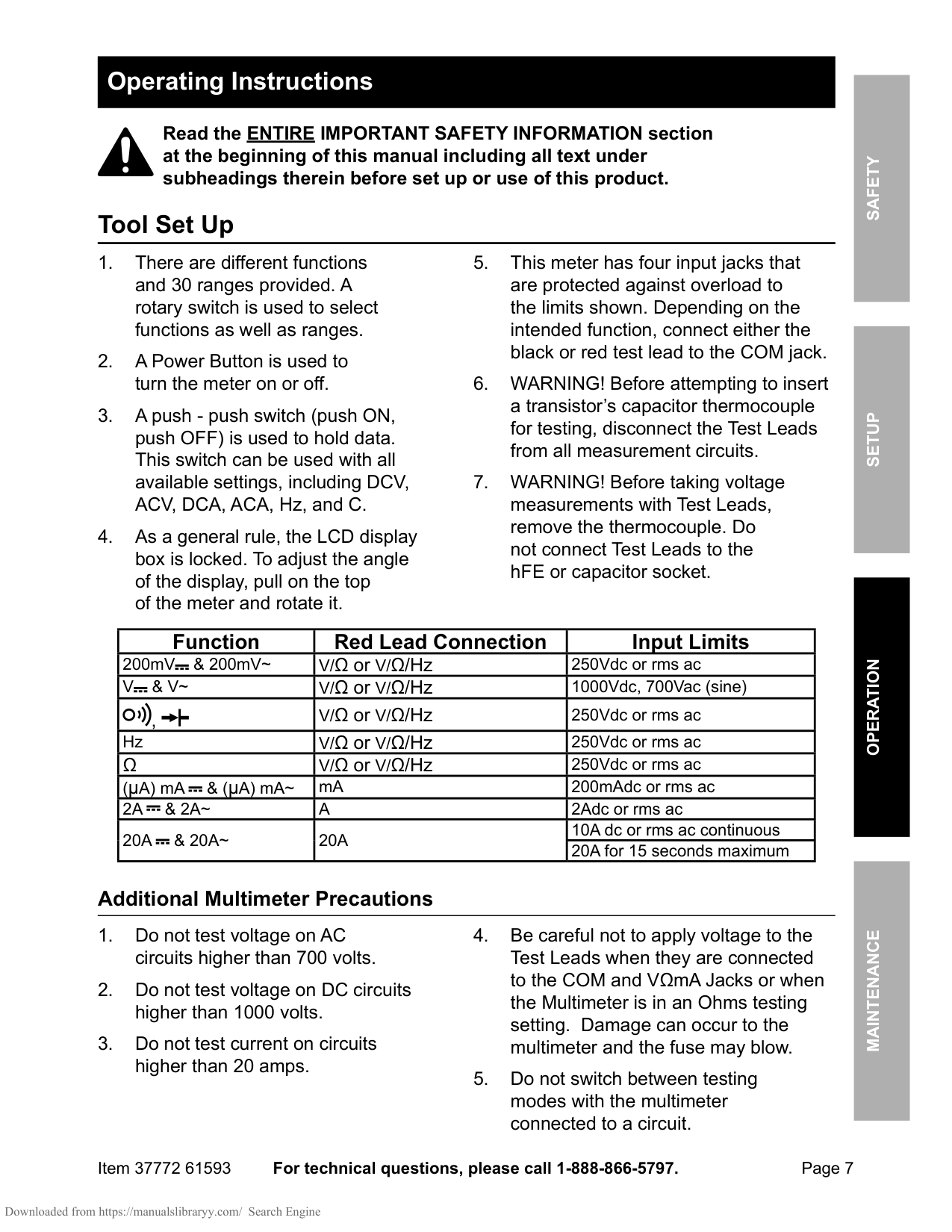
Page 7 For technical questions, please call 1-888-866-5797. Item 37772 61593 Safety Operation Maintenance Setup Operating Instructions Read the ENTIRE IMPORTANT SAFETY INFORMATION section at the beginning of this manual including all text under subheadings therein before set up or use of this product. Tool Set Up
V
& V~
V/Ω or V/Ω/Hz 1000Vdc, 700Vac (sine) , V/Ω or V/Ω/Hz 250Vdc or rms ac Hz V/Ω or V/Ω/Hz 250Vdc or rms acΩ
V/Ω or V/Ω/Hz 250Vdc or rms ac (μA) mA & (μA) mA~ mA 200mAdc or rms ac2A
& 2A~
A
2Adc or rms ac20A
& 20A~
20A
10A dc or rms ac continuous 20A for 15 seconds maximum Additional Multimeter Precautions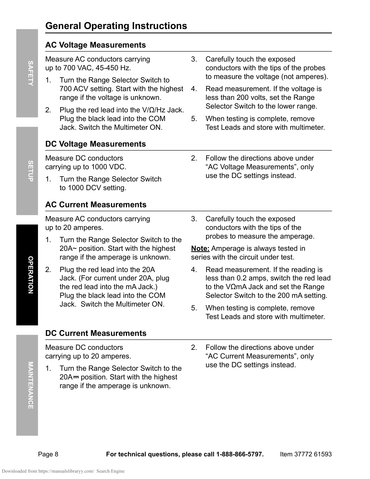
Page 8 For technical questions, please call 1-888-866-5797. Item 37772 61593 Safety Operation Maintenance Setup General Operating Instructions AC Voltage Measurements Measure AC conductors carrying up to 700 VAC, 45-450 Hz.
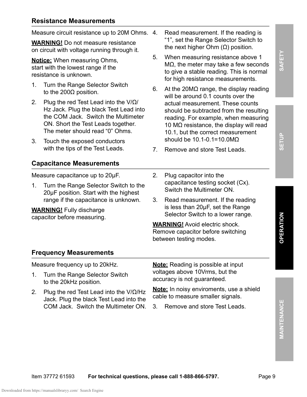
Page 9 For technical questions, please call 1-888-866-5797. Item 37772 61593 Safety Operation Maintenance Setup Resistance Measurements Measure circuit resistance up to 20M Ohms. WARNING! Do not measure resistance on circuit with voltage running through it. Notice: When measuring Ohms, start with the lowest range if the resistance is unknown.
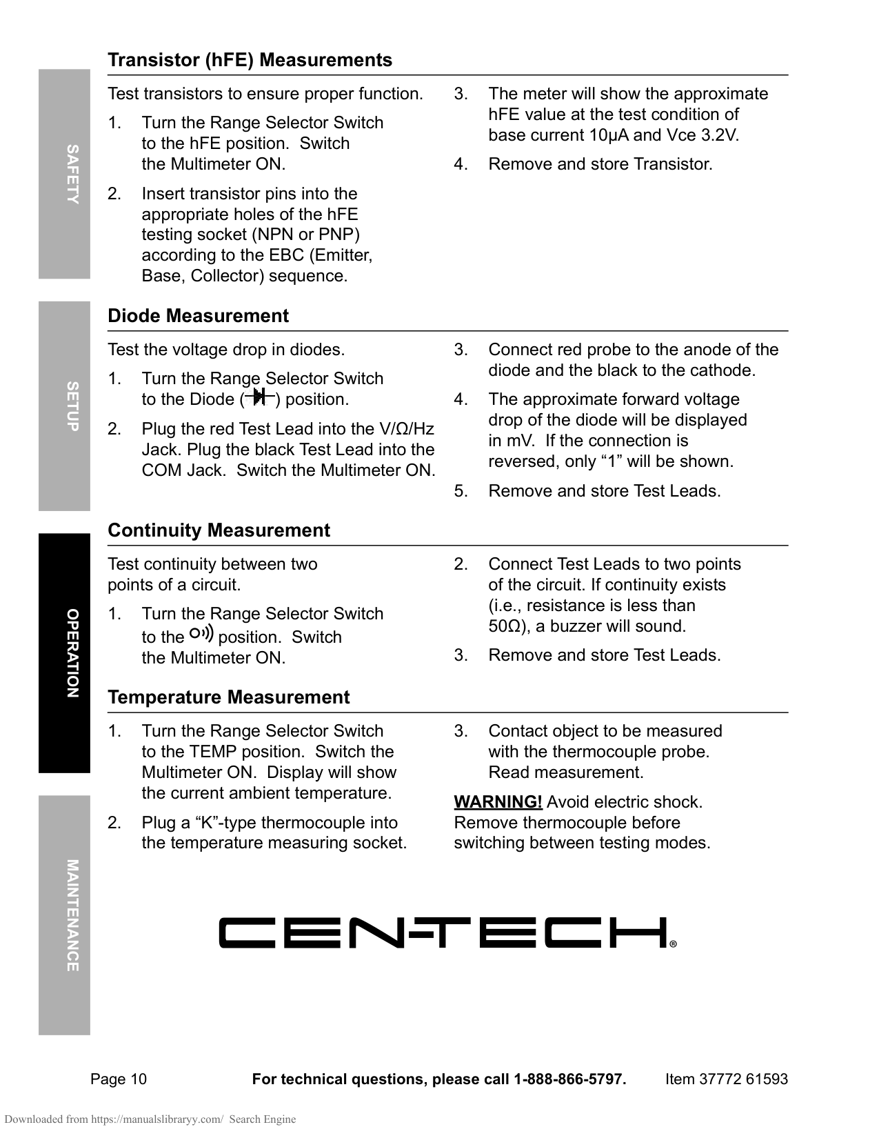
Page 10 For technical questions, please call 1-888-866-5797. Item 37772 61593 Safety Operation Maintenance Setup Transistor (hFE) Measurements Test transistors to ensure proper function.
Page 11 For technical questions, please call 1-888-866-5797. Item 37772 61593 Safety Operation Maintenance Setup Maintenance and Servicing Procedures not specifically explained in this manual must be performed only by a qualified technician. Cleaning, Maintenance, and Lubrication
Limited 90 Day Warranty Harbor Freight Tools Co. makes every effort to assure that its products meet high quality and durability standards, and warrants to the original purchaser that this product is free from defects in materials and workmanship for the period of 90 days from the date of purchase. This warranty does not apply to damage due directly or indirectly, to misuse, abuse, negligence or accidents, repairs or alterations outside our facilities, criminal activity, improper installation, normal wear and tear, or to lack of maintenance. We shall in no event be liable for death, injuries to persons or property, or for incidental, contingent, special or consequential damages arising from the use of our product. Some states do not allow the exclusion or limitation of incidental or consequential damages, so the above limitation of exclusion may not apply to you.