Ask AI
— answers from the official manualAnswers from the official manual.
Common questions
Common Questions
30 totalWhere can I find the Honeywell TC300 Commercial Thermostat manual and user guide?
The TC300 Commercial Thermostat manual is available as a Configuration and User Guide document (31-00644-01 | Rev 11-23). This comprehensive manual covers installation, commissioning, operation, and configuration of the thermostat. Additional reference documents include the Datasheet (31-00645), Mounting & Installation instructions (31-00642), Pocket guide (31-00648), BACnet Integration guide (31-00646), and Modbus Integration guide (31-00670). (Page 13)
What are the power requirements and specifications for the TC300 thermostat?
The TC300 thermostat requires 24VAC 50/60Hz power with a working voltage range of 20-30VAC from a UL listed class-2 transformer or IEC 61558 listed transformer. Maximum power consumption is 8.5VA at 24VAC (355mA), with minimum load of 4VA and maximum load of 96VA when all digital outputs are on. (Page 16)
How do I perform the initial setup and boot-up of the TC300 thermostat?
The thermostat automatically powers up after mounting on the wallplate. During boot-up, you'll navigate through several configuration screens: assigning a device name, connecting to network (BACnet MS/TP or Modbus), selecting temperature units, setting date and time, configuring equipment type, setting system switch, configuring occupancy setpoints, creating an installer passcode (4-12 characters with alphanumeric/symbol), entering service information, and optionally setting up user management. (Pages 35-42)
What types of equipment and valves does the TC300 thermostat support?
The TC300 supports 4-pipe dual coil, 4-pipe single coil, and 2-pipe single coil fan coil equipment. Valve options include On/Off valves (normally closed or normally open), Floating valves, Modulating valves, and 6-Way Modulating valves. It also supports 1-3 speed or variable speed fans, discharge air control, dehumidification with/without reheat, and auxiliary heating options (peripheral or supplemental). (Pages 50-54)
How do I configure the I/O terminal assignments on the TC300?
Access I/O terminal assignment through the Configuration menu by tapping Configuration > Equipment > Equipment & I/O > I/O Assignment. Tap the plus button to assign terminals for equipment functions. The system will pre-assign terminals based on configured equipment, but you can override defaults as needed. If conflicts occur (same terminal assigned to two functions), resolve them by reassigning terminals using the Resolve Conflict button. (Pages 57-59)
What sensors are supported by the TC300 thermostat?
The TC300 supports multiple sensor types including NTC 20K, NTC 10K Type II, NTC 10K Type III, and Sylk sensors for temperature measurement. For other functions, it supports occupancy sensors (dry contact), proof of airflow sensors (DPS200, DPS400, DPS1000, MCS, CS, CSP switches), discharge air temperature sensors, space temperature sensors (including TR40, TR40-H, TR40-CO2 models), changeover pipe sensors, changeover switches, and drain pan/leak detectors (float switches or water sensors). Onboard sensors include temperature (40-100°F heating, 50-99°F cooling range, ±1.5°F accuracy) and humidity (20-90% RH range, ±5% RH accuracy). (Pages 19-20, 62)
Show 24 more questions
How do I enable and use the Service Mode on the TC300?
What are the operating temperature and environmental specifications for the TC300?
How do I configure BACnet MS/TP or Modbus communication on the TC300?
What safety precautions should I follow when installing and maintaining the TC300 thermostat?
How do I manage different user roles on the TC300?
How do I reset the thermostat to default settings?
How do I adjust the temperature on the home screen?
How do I manage user access and roles on the TC300?
Where can I find information about the thermostat's terminal connections?
What should I do if I need to reset my TC300 thermostat to default settings?
What should I do before booting up the thermostat?
How do I access device configuration settings?
Where is the Terminal Identification information located?
What display management options are available?
Where can I find information about security requirements?
What is the TC300 thermostat designed for?
Where can I find the technical specifications for the TC300?
What safety information should I review before installation?
What are the prerequisites before I can start using my TC300 thermostat?
How do I turn on my TC300 thermostat for the first time?
What are the physical dimensions of the TC300 thermostat?
What important safety information should I know before installing the TC300?
How do I configure the basic settings on my TC300 thermostat?
Where can I find security information and view security logs?
Full Manual
123 pages
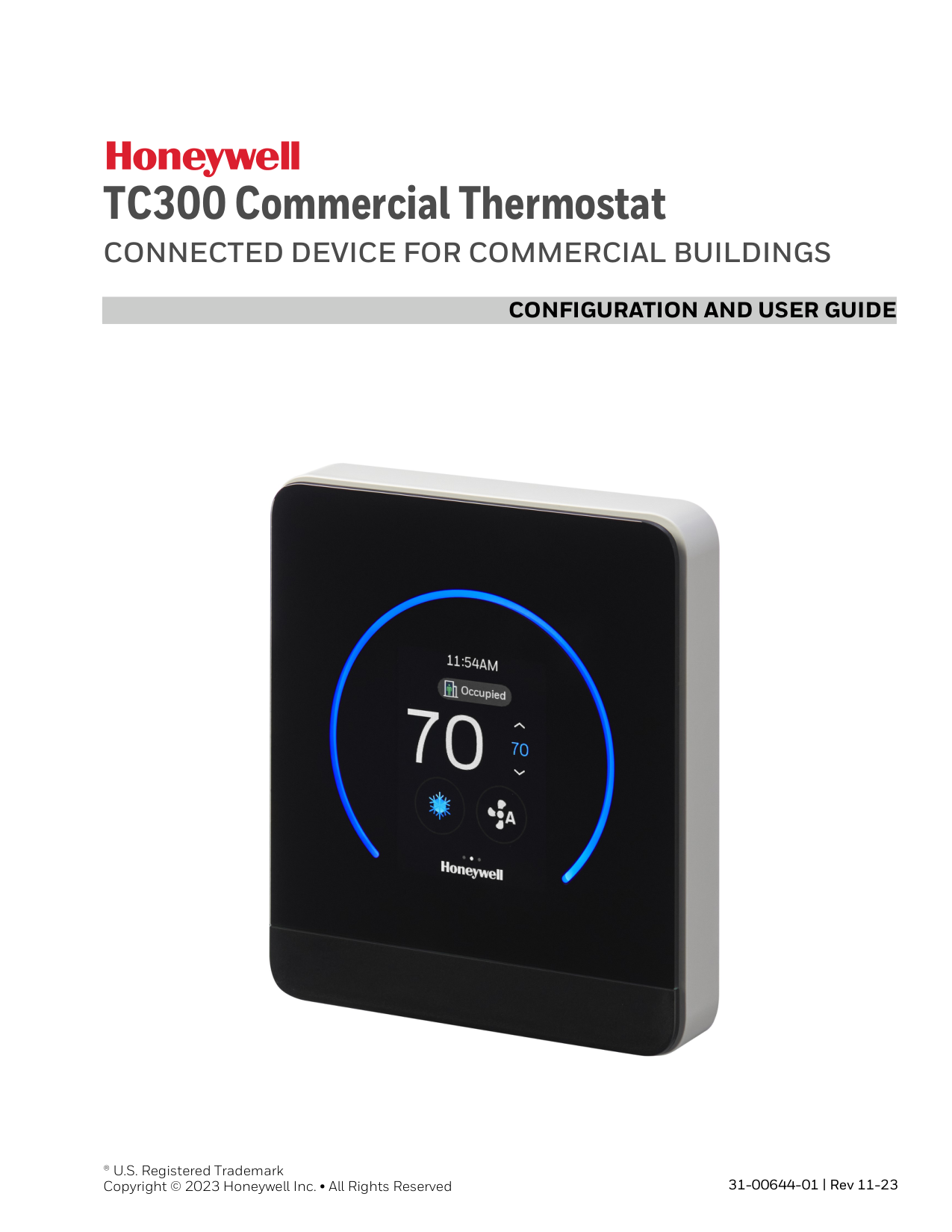
Configuration And User Guide
® U.S. Registered Trademark Copyright © 2023 Honeywell Inc. • All Rights Reserved 31-00644-01 | Rev 11-23 TC300 Commercial ThermostatConnected Device For Commercial Buildings
3 Table of contents Important Safety Information and Installation Precautions..................................8 Introduction................................................................................................................................... 11 About TC300 Thermostat .................................................................................................. 12 Features.................................................................................................................................... 12 Equipment control features ........................................................................................... 12 Intended audience and assumed knowledge............................................................ 13 Reference documents......................................................................................................... 13 Abbreviation and nomenclature..................................................................................... 13 Conventions............................................................................................................................ 14 Dimensions ............................................................................................................................. 15 Technical specifications..................................................................................................... 16 Terminal Identification ....................................................................................................... 21 Terminal assignment........................................................................................................... 23 Security requirement........................................................................................................... 24 Overview.......................................................................................................................................... 25 Home screen: Temperature reading and adjustment............................................ 26 Quick access screen (right side screen): Device configuration.......................... 27 Ambiance screen (left side screen): Sensor reading .............................................. 28 Home screen icon overview.............................................................................................. 28 Inactive display modes....................................................................................................... 30 Display timeout properties ............................................................................................... 31 Getting Started............................................................................................................................. 33 Prerequisites........................................................................................................................... 34 Boot-up the thermostat ..................................................................................................... 35 Configuration................................................................................................................................ 43
4
Tc300 Thermostat User Guide
Configuration screen...........................................................................................................44 Basic configuration ..............................................................................................................45 Equipment configuration ..................................................................................................49 I/O terminal assignment....................................................................................................57 Configuring sensors.............................................................................................................59 Managing System switch...................................................................................................64 Managing Discharge air control .....................................................................................65 Managing Dehumidification ............................................................................................67 Managing Valve cycle..........................................................................................................68 Advanced configuration .....................................................................................................69 Managing Setpoint options ..............................................................................................70 Managing Cooling options................................................................................................72 Managing Heating options ...............................................................................................74 Managing Pipe sensor thresholds .................................................................................75 Managing Valve purge ........................................................................................................76 Miscellaneous ........................................................................................................................77 Managing Service mode.....................................................................................................77 Managing Standby action .................................................................................................79 Viewing the Security log .....................................................................................................80 Viewing the Diagnostics.....................................................................................................80 Managing connection.........................................................................................................81 User management ................................................................................................................85 Configuring the user roles.................................................................................................85 Configuring Home screen (Display Management) .................................................88 Managing display settings................................................................................................89 Reset to default......................................................................................................................91 Viewing the system status.................................................................................................92 Managing Setpoints.............................................................................................................93 Changing the system mode..............................................................................................95 Changing the fan speed .....................................................................................................96 Alarms ..............................................................................................................................................97 Alarms........................................................................................................................................97 Alarm notification signs .....................................................................................................97 Alarm notification .................................................................................................................98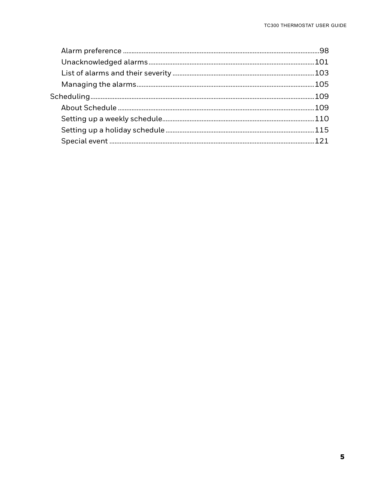
5
Tc300 Thermostat User Guide
Alarm preference ...................................................................................................................98 Unacknowledged alarms.................................................................................................101 List of alarms and their severity ...................................................................................103 Managing the alarms........................................................................................................105 Scheduling...................................................................................................................................109 About Schedule ...................................................................................................................109 Setting up a weekly schedule.........................................................................................110 Setting up a holiday schedule .......................................................................................115 Special event ........................................................................................................................121
6
Tc300 Thermostat User Guide
7
Tc300 Thermostat User Guide
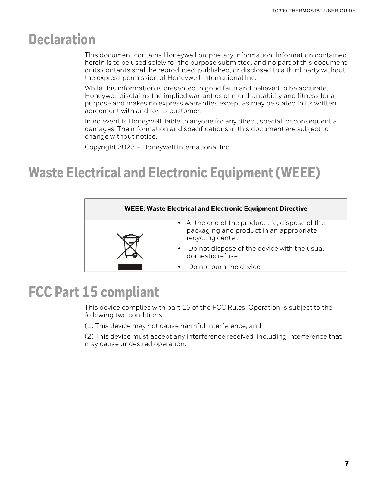
Declaration This document contains Honeywell proprietary information. Information contained herein is to be used solely for the purpose submitted, and no part of this document or its contents shall be reproduced, published, or disclosed to a third party without the express permission of Honeywell International Inc. While this information is presented in good faith and believed to be accurate, Honeywell disclaims the implied warranties of merchantability and fitness for a purpose and makes no express warranties except as may be stated in its written agreement with and for its customer. In no event is Honeywell liable to anyone for any direct, special, or consequential damages. The information and specifications in this document are subject to change without notice. Copyright 2023 – Honeywell International Inc. Waste Electrical and Electronic Equipment (WEEE) FCC Part 15 compliant This device complies with part 15 of the FCC Rules. Operation is subject to the following two conditions: (1) This device may not cause harmful interference, and (2) This device must accept any interference received, including interference that may cause undesired operation. WEEE: Waste Electrical and Electronic Equipment Directive • At the end of the product life, dispose of the packaging and product in an appropriate recycling center. • Do not dispose of the device with the usual domestic refuse. • Do not burn the device.
8 Important Safety Information and Installation Precautions
Tc300 Thermostat User Guide
Regulation (EC) No 1907/2006 According to Article 33 of Reach Regulation, be informed that the substances listed below may be contained in these products above the threshold level of 0.1% by weight of the listed article. Important Safety Information and Installation Precautions Read all instructions Failure to follow all instructions may result in equipment damage or a hazardous condition. Read all instructions carefully before installing equipment. When performing any work (installation, mounting, start-up), all manufacturer instructions and in particular the Mounting Instructions (31-00642) are to be observed. • TC300 Thermostat may be installed and mounted only by authorized and trained personnel. • It is recommended that devices be kept at room temperature for at least 24 hours before applying power. This is to allow any condensation resulting from low shipping/storage temperatures to evaporate. • Do not open TC300 Thermostat, as it contains no user-serviceable parts inside! • Investigated according to United States Standard UL- 60730-1, and UL60730-2-2014/30/Eu.
• Product standards are EN 60730-1 and EN 60730-2-9. • TC300 Thermostat is Class B digital apparatus and complies with Canadian ICES-
Important Safety Information and Installation Precautions 9
Tc300 Thermostat User Guide
measurement or detection device should be made immediately before starting work and when work resumes. Lightning and high-voltage danger Most electrical injuries involving low-voltage wiring result from sudden, unexpected high voltages on normally low voltage wiring. Low-voltage wiring can carry hazardous high voltages under unsafe conditions. Never install or connect wiring or equipment during electrical storms. Improperly protected wiring can carry a fatal lightning surge for many miles. All outdoor wiring must be equipped with properly grounded and listed signal circuit protectors, which must be installed in compliance with local, applicable codes. Never install wiring or equipment while standing in water. Wiring and equipment separations All wiring and controllers must be installed to minimize the possibility of accidental contact with other potentially hazardous and disruptive power and lighting wiring. Never place 24VAC or communications wiring near other bare power wires, lightning rods, antennas, transformers, or steam or hot water pipes. Never place wire in any conduit, box, channel, duct or other enclosure containing power or lighting circuits of any type. Always provide adequate separation of communications wiring and other electrical wiring according to code. Keep wiring and controllers at least six feet from large inductive loads (power distribution panels, lighting ballasts, motors, etc.). Failure to follow these guidelines can introduce electrical interference and cause the system to operate erratically. Warning By using this Honeywell literature, you agree that Honeywell will have no liability for any damages arising out of your use, or modification to, the literature. You will defend and indemnify Honeywell, its affiliates and subsidiaries, from and against any liability, cost, or damages, including attorneys' fees, arising out of, or resulting from, any modification to the literature by you. The material in this document is for information purposes only. The content and the product it describes are subject to change without notice. Honeywell makes no representations or warranties with respect to this document. In no event shall Honeywell be liable for technical or editorial omissions or mistakes in this document, nor shall it be liable for any damages, direct or incidental, arising out of or related to the use of this document. No part of this document may be reproduced in any form or by any means without prior written permission from Honeywell. Safety Information as per EN60730-1 TC300 Thermostat is intended for commercial and residential environments. TC300 Thermostat is an independently mounted electronic control system with fixed wiring. TC300 Thermostat is used for the purpose of building HVAC control and is suitable for use only in non-safety controls for installation on or in appliances.
10 Important Safety Information and Installation Precautions
Tc300 Thermostat User Guide
Chapter
1 11 Introduction This chapter contains brief description of the TC300 thermostat and its hardware specifications. Related topics About TC300 Thermostat Features Intended audience and assumed knowledge Reference documents Abbreviation and nomenclature Conventions Dimensions Technical specifications Terminal Identification Terminal assignment Security requirement
12 About TC300 Thermostat
1 - Introduction
About TC300 Thermostat TC300 Thermostat is an advanced, highly configurable device providing building automation connectivity well-suited for commercial building applications. The product has flexible I/O that will satisfy the needs of most 2-pipe or 4-pipe fan coil applications including floating, modulating, and 6-way Modulating valves plus multi-speed and variable speed fan and various external sensors with a minimum SKU complexity. Other key supported functions include dehumidification w/reheat using an embedded humidity sensor, auxiliary heat functions, and more rapid transitional 2-pipe system seasonal changeover. This device supports BACnet MS/TP and Modbus communications via RS485 bus as is needed for typical HVAC building control systems. This same bus is used to facilitate future firmware updates and enhanced functionality as they are released to the market. The integral intelligent control algorithms plus scheduling help to achieve the perfect balance between Energy Efficiency and Comfort. The thermostat utilizes an attractive, color, capacitive-touch screen interface providing an intuitive configuration process with minimal installer training. This functionality is enhanced through the usage of embedded help screens reducing reliance on technical manuals for complex installation. Features • Color, capacitive-touch screen display for intuitive, fast commissioning and exceptional user experience. • Multiple, configurable user types with customizable privileges to prevent unauthorized usage. • Embedded system monitoring screen for equipment and I/O status. • Customizable daily schedule for Occupancy set points. Support upto 10 Holidays including floating or specific date. Support up to 10 special events including specific date. For each holiday or special event can configure 3 period of events. • Advanced commercial control algorithms such as auto changeover. • Customizable inactive display modes, Auto dim display, always on, or dark mode. • A LED ring indicator to show the operational status. • Real-Time Clock time keeping accuracy with 72 hour retention during power loss. • Thermostat can be configured via HMI, or BACnet. Equipment control features • Fan coil, On/Off Valve, Floating Valve, Modulating Valve, and 6-Way Modulating Valve. • Discharge Air Control • 1-3 or variable speed fan • Dehumidification with and without reheat. • Enhanced 2-Pipe fan coil functionality during seasonal or system changeover providing heating or cooling functionality before CW/HW has reached optimal operating temperature. • Service mode for manually enabling outputs for faster diagnostics and equipment testing. • Auxiliary heating options supporting peripheral or supplemental types • Auto mode to switch between heating and cooling according to the current space temperature
Intended audience and assumed knowledge 13
Intended Audience And Assumed Knowledge
• Staging control, PID Tuning, DAT Lockout, Modulating control • System Switch and Ventilation options. • Integration with a variety of external wired sensor types including: Discharge air, Drain pan, occupancy, Proof or airflow, Space temp, CO2, and Humidity. • Complies with ASHRAE guideline 36-2021, Section 5.22 sequence of operations for high- performance operation when using floating/modulating valves and multi-speed/variable speed fan. Intended audience and assumed knowledge This document provides information about installing and commissioning a TC300 Thermostat. It also shows how to operate the user interface. It is assumed that the user is trained and familiar with HVAC concepts. IMPORTANT: Always install equipment in accordance with the National Electric Code and in a manner acceptable to the local authority having jurisdiction (AHJ). No guidelines, instructions, installation practices, or other information presented in this guide may be interpreted to supersede or modify the local codes and practices of theAhj.
Reference documents • TC300 Commercial Thermostat Datasheet (31-00645) • TC300 Commercial Thermostat Mounting & Installation instructions (31-00642) • TC300 Commercial Thermostat Pocket guide (31-00648) • TC300 Deco Plate Pocket guide (31-00657) • TC300 BACnet Integration guide (31-00646) • TC300 Modbus Integration guide (31-00670) Abbreviation and nomenclature Abbreviation DefinitionAhu
Air Handling UnitRtu
Roof Top UnitVac
Volts AC (Alternating Current)Vdc/ Dc
Volts DC (Direct Current)Otw
Over-The-WireBms
Building Management System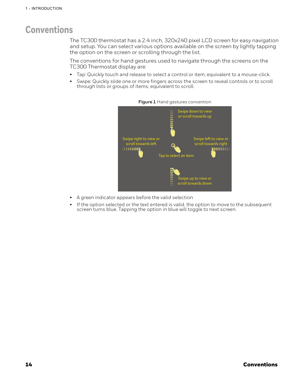
14 Conventions
1 - Introduction
Conventions The TC300 thermostat has a 2.4 inch, 320x240 pixel LCD screen for easy navigation and setup. You can select various options available on the screen by lightly tapping the option on the screen or scrolling through the list. The conventions for hand gestures used to navigate through the screens on the TC300 Thermostat display are: • Tap: Quickly touch and release to select a control or item; equivalent to a mouse-click. • Swipe: Quickly slide one or more fingers across the screen to reveal controls or to scroll through lists or groups of items; equivalent to scroll. Figure 1 Hand gestures convention • A green indicator appears before the valid selection • If the option selected or the text entered is valid, the option to move to the subsequent screen turns blue. Tapping the option in blue will toggle to next screen. Swipe right to view or scroll towards left Swipe down to view or scroll towards up Swipe up to view or scroll towards down Tap to select an item Swipe left to view or scroll towards right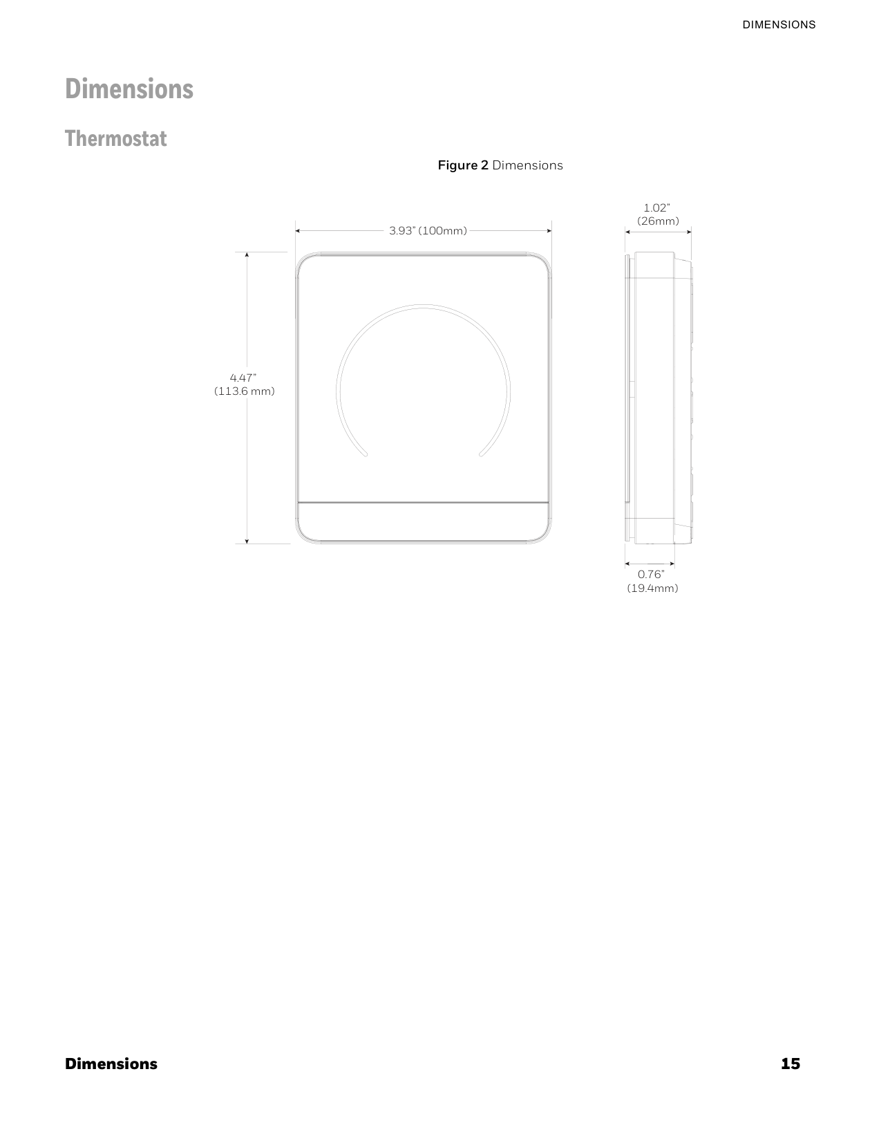
Dimensions 15
Dimensions
Dimensions Thermostat Figure 2 Dimensions 3.93” (100mm) 4.47” (113.6 mm) 1.02” (26mm) 0.76” (19.4mm)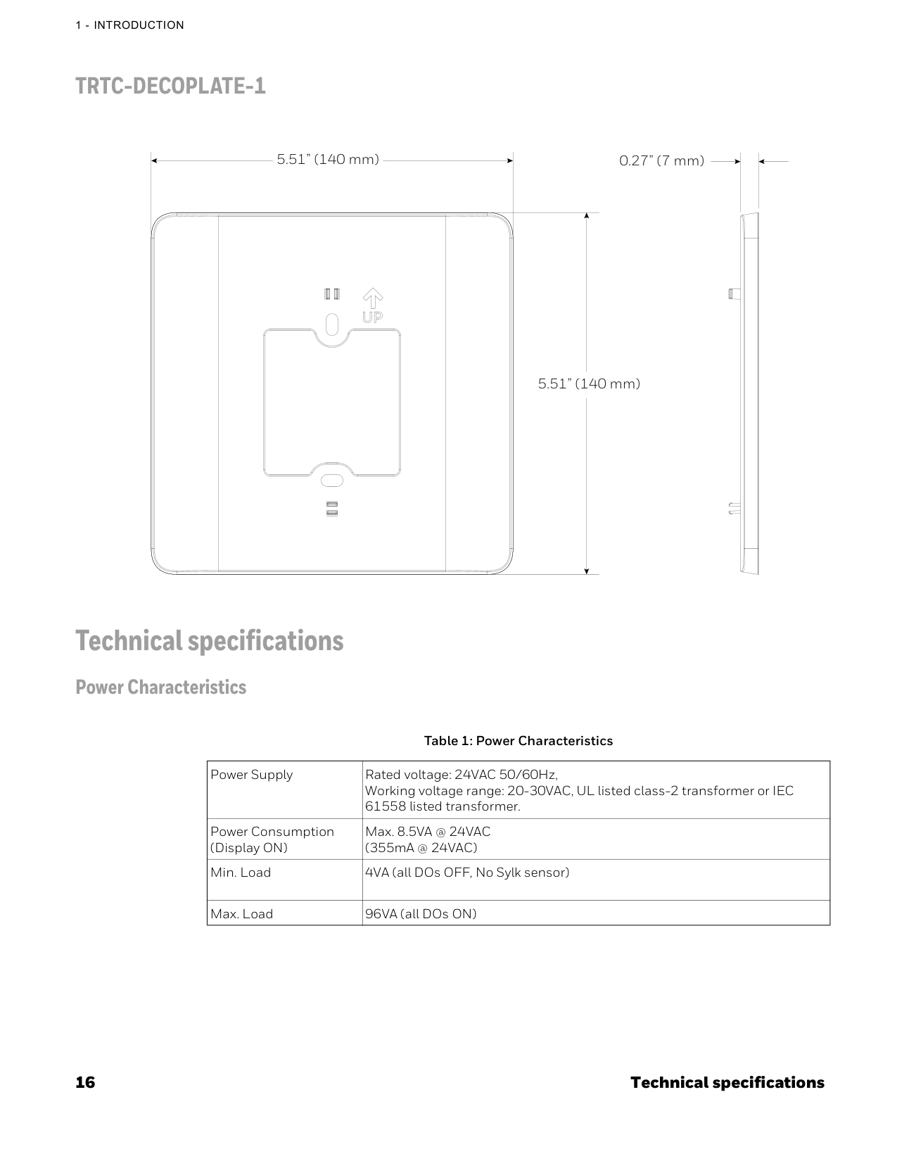
16 Technical specifications
1 - Introduction
Trtc-Decoplate-1
Technical specifications Power Characteristics 5.51” (140 mm) 5.51” (140 mm) 0.27” (7 mm) Table 1: Power Characteristics Power Supply Rated voltage: 24VAC 50/60Hz, Working voltage range: 20-30VAC, UL listed class-2 transformer or IEC 61558 listed transformer. Power Consumption (Display ON) Max. 8.5VA @ 24VAC (355mA @ 24VAC) Min. Load 4VA (all DOs OFF, No Sylk sensor) Max. Load 96VA (all DOs ON)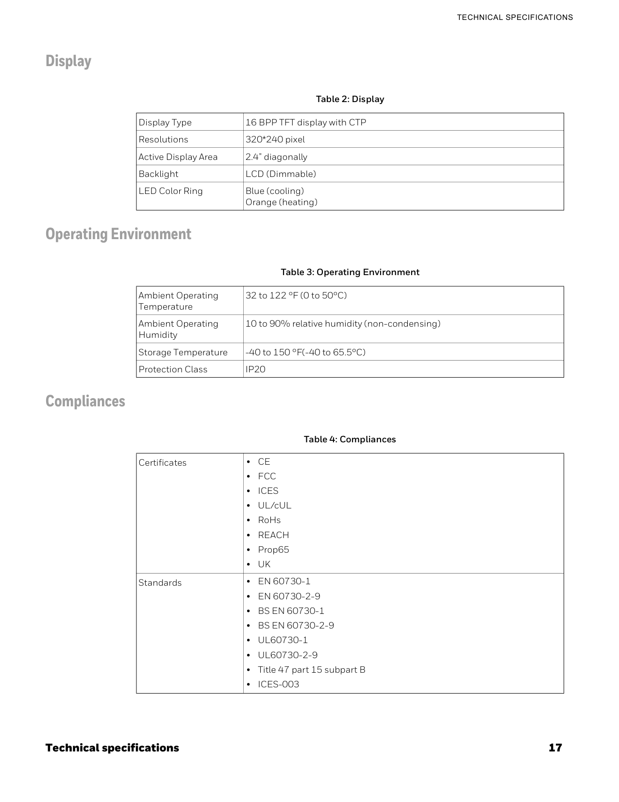
Technical specifications 17
Technical Specifications
Display Operating Environment Compliances Table 2: Display Display Type 16 BPP TFT display with CTP Resolutions 320*240 pixel Active Display Area 2.4” diagonally Backlight LCD (Dimmable) LED Color Ring Blue (cooling) Orange (heating) Table 3: Operating Environment Ambient Operating Temperature 32 to 122 °F (0 to 50°C) Ambient Operating Humidity 10 to 90% relative humidity (non-condensing) Storage Temperature -40 to 150 °F(-40 to 65.5°C) Protection ClassIp20
Table 4: Compliances Certificates •Ce
•Fcc
•Ices
• UL/cUL • RoHs •Reach
• Prop65 •Uk
Standards •En 60730-1
•En 60730-2-9
•Bs En 60730-1
•Bs En 60730-2-9
•Ul60730-1
•Ul60730-2-9
• Title 47 part 15 subpart B •Ices-003
18 Technical specifications
1 - Introduction
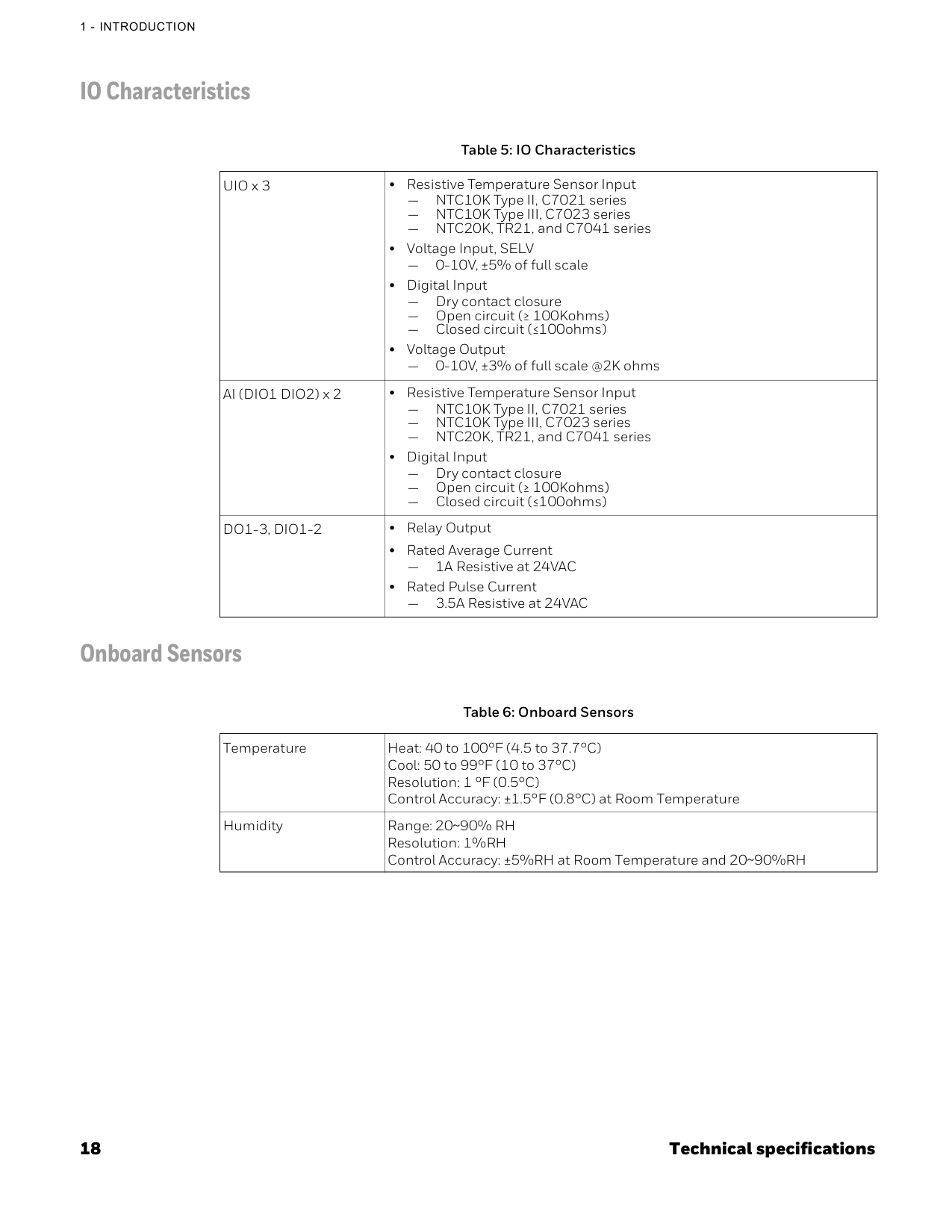
IO Characteristics Onboard Sensors Table 5: IO Characteristics UIO x 3 • Resistive Temperature Sensor Input — NTC10K Type II, C7021 series — NTC10K Type III, C7023 series — NTC20K, TR21, and C7041 series • Voltage Input, SELV — 0-10V, ±5% of full scale • Digital Input — Dry contact closure — Open circuit (≥ 100Kohms) — Closed circuit (≤100ohms) • Voltage Output — 0-10V, ±3% of full scale @2K ohms AI (DIO1 DIO2) x 2 • Resistive Temperature Sensor Input — NTC10K Type II, C7021 series — NTC10K Type III, C7023 series — NTC20K, TR21, and C7041 series • Digital Input — Dry contact closure — Open circuit (≥ 100Kohms) — Closed circuit (≤100ohms)Do1-3, Dio1-2
• Relay Output • Rated Average Current — 1A Resistive at 24VAC • Rated Pulse Current — 3.5A Resistive at 24VAC Table 6: Onboard Sensors Temperature Heat: 40 to 100°F (4.5 to 37.7°C) Cool: 50 to 99°F (10 to 37°C) Resolution: 1 °F (0.5°C) Control Accuracy: ±1.5°F (0.8°C) at Room Temperature Humidity Range: 20~90% RH Resolution: 1%RH Control Accuracy: ±5%RH at Room Temperature and 20~90%RH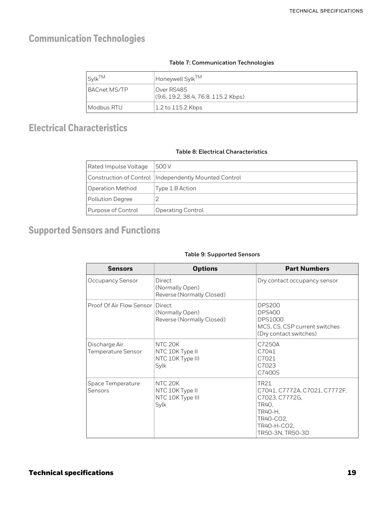
Technical specifications 19
Technical Specifications
Communication Technologies Electrical Characteristics Supported Sensors and Functions Table 7: Communication Technologies SylkTM Honeywell SylkTM BACnet MS/TP Over RS485 (9.6, 19.2, 38.4, 76.8, 115.2 Kbps) Modbus RTU 1.2 to 115.2 Kbps Table 8: Electrical Characteristics Rated Impulse Voltage500 V
Construction of Control Independently Mounted Control Operation Method Type 1.B Action Pollution Degree 2 Purpose of Control Operating Control Table 9: Supported Sensors Sensors Options Part Numbers Occupancy Sensor Direct (Normally Open) Reverse (Normally Closed) Dry contact occupancy sensor Proof Of Air Flow Sensor Direct (Normally Open) Reverse (Normally Closed)Dps200
Dps400
Dps1000
MCS, CS, CSP current switches (Dry contact switches) Discharge Air Temperature SensorNtc 20K
NTC 10K Type II NTC 10K Type III SylkC7250A
C7041
C7021
C7023
C7400S
Space Temperature SensorsNtc 20K
NTC 10K Type II NTC 10K Type III SylkTr21
C7041, C7772A, C7021, C7772F,
C7023, C7772G,
Tr40,
Tr40-H,
Tr40-Co2,
Tr40-H-Co2,
Tr50-3N, Tr50-3D
20 Technical specifications
1 - Introduction
Part Numbers Changeover Pipe Sensor NTC 20K NTC 10K Type II NTC 10K Type IIIC7250A
C7041
C7021
C7023
Changeover Switch Closed with heat Closed with cool Digital input Drain Pan / Leak Detector Direct (Normally Open) Reverse (Normally Closed Dry contact float switch or water sensor Table 9: Supported Sensors Sensors Options Part Numbers Table 10: Part NumbersTc300B-G
RS485 BACnet MS/TP and ModbusTrtc-Decoplate-1
TC300 deco plate for NA junction boxes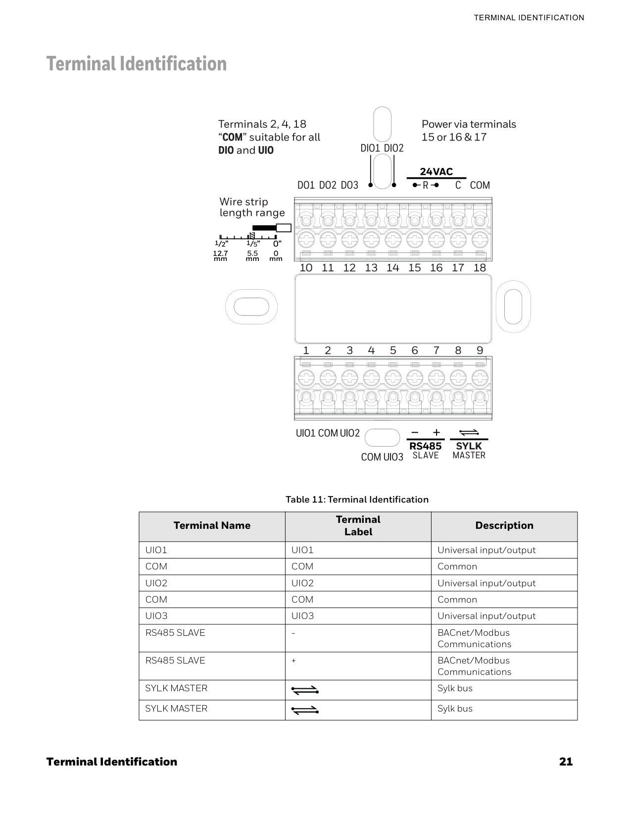
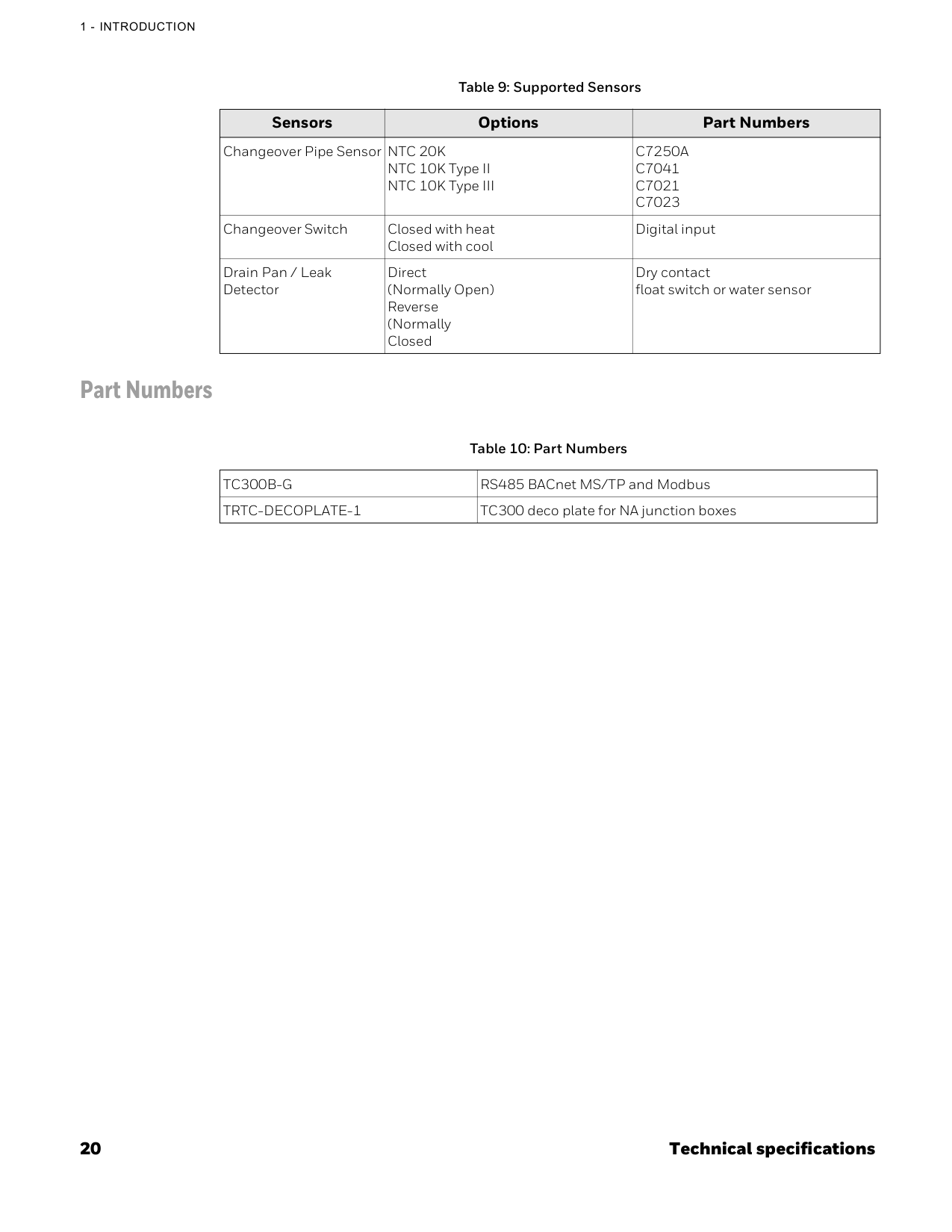
Terminal Identification 21
Terminal Identification
Terminal Identification Table 11: Terminal Identification Terminal Name Terminal Label DescriptionUio1
Uio1
Universal input/outputCom
Com
CommonUio2
Uio2
Universal input/outputCom
Com
CommonUio3
Uio3
Universal input/outputRs485 Slave
Rs485 Slave
+ BACnet/Modbus CommunicationsSylk Master
Sylk busSylk Master
Sylk bus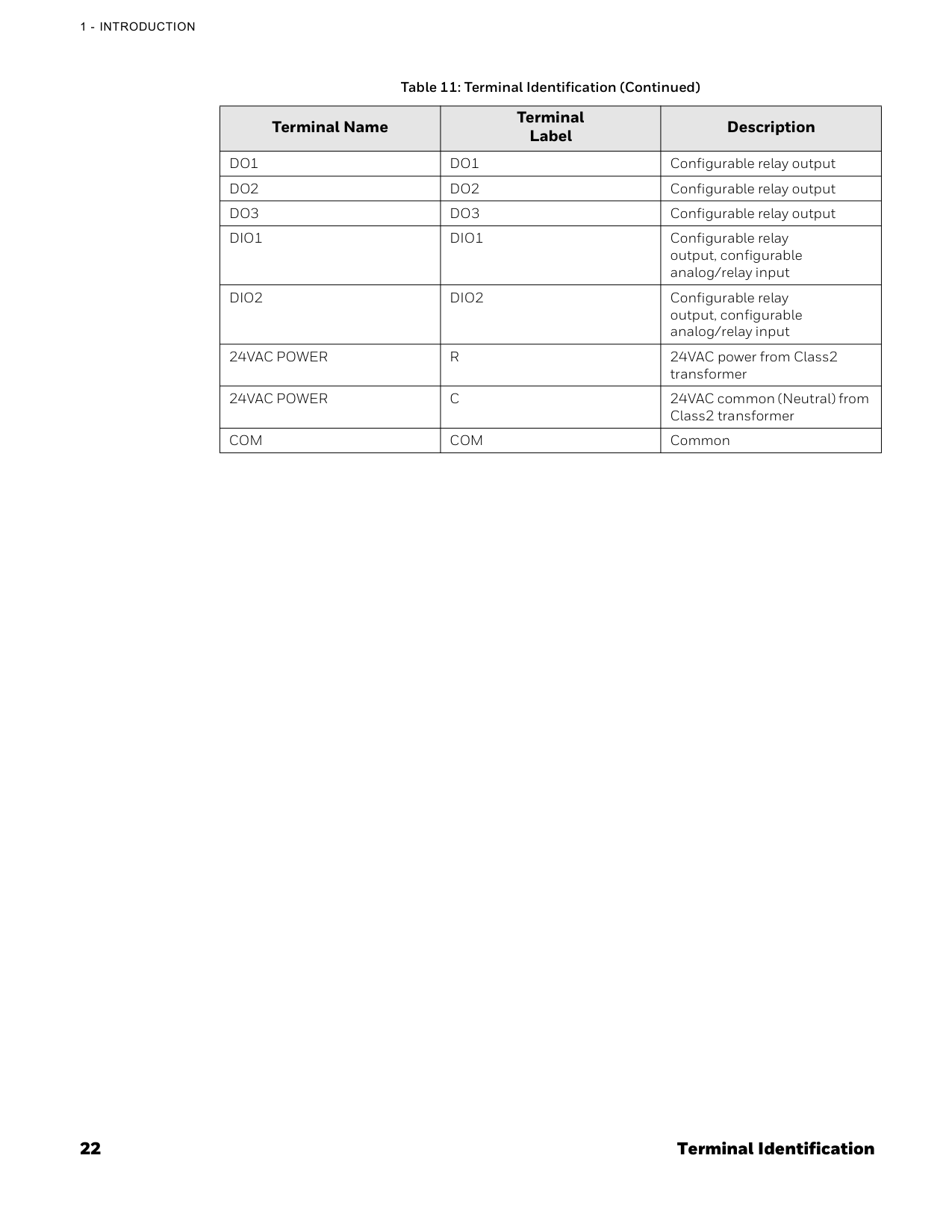
22 Terminal Identification
1 - Introduction
Do1
Do1
Configurable relay outputDo2
Do2
Configurable relay outputDo3
Do3
Configurable relay outputDio1
Dio1
Configurable relay output, configurable analog/relay inputDio2
Dio2
Configurable relay output, configurable analog/relay input24Vac Power
R
24VAC power from Class2 transformer24Vac Power
C
24VAC common (Neutral) from Class2 transformerCom
Com
Common Table 11: Terminal Identification (Continued) Terminal Name Terminal Label Description
Terminal assignment 23
Terminal Assignment
Terminal assignment Table 12: Terminal assignment Type Terminal Label Terminal Assignments Default Inputs Outputs Digital OutputDo1
Do1
On/Off HeatNa
Heating On/Off, Heating Floating Open, Cooling Floating Open, Valve On/Off, Valve Floating Open, Changeover Valve, Fan Command, High Speed Fan, Medium Speed Fan, Low Speed Fan, Auxiliary Heat, Heat Stage1, Valve Stage1 Note: Changeover valve used to switch between heating and cooling mode.Do2
Do2
On/Off CoolNa
Heating Floating Close, Cooling Floating Close, Cooling On/Off, Valve Floating Close, Changeover Valve, Fan Command, High Speed Fan, Medium Speed Fan, Low Speed Fan, Auxiliary Heat, Cool Stage1D03
Do3
Na
Na
Cooling Floating Open, Changeover Valve, Fan Command, High Speed Fan, Medium Speed Fan, Low Speed Fan, Auxiliary Heat, Heat Stage1, Cool Stage1Dio1
Dio1
Na
Discharge Air Sensor, Drain Pan Sensor, Occupancy Sensor, Proof of Airflow, Pipe Sensor, Space Temp Sensor, Changeover Switch Cooling Floating Close, Changeover Valve, Fan Command, High Speed Fan, Medium Speed Fan, Low Speed Fan, Auxiliary HeatDio2
Dio2
Na
Discharge Air Sensor, Drain Pan Sensor, Occupancy Sensor, Proof of Airflow, Pipe Sensor, Space Temp Sensor, Changeover Switch Changeover Valve, Fan Command, High Speed Fan, Medium Speed Fan, Low Speed Fan, Auxiliary Heat Universal Input/ OutputUio1
Uio1
Na
Discharge Air Sensor, Drain Pan Sensor, Occupancy Sensor, Proof of Airflow, Pipe Sensor, Space Temp Sensor, Changeover Switch 6-Way Valve, Modulating Cool, Modulating Heat, Modulating Valve, Variable Speed FanUio2
Uio2
Na
Uio3
Uio3
Na
24 Security requirement
1 - Introduction
Security requirement System Environmental Considerations An Internet firewall is required to isolate the Thermostat. Unprotected Internet connections can expose and damage the thermostat system and facility components to cyber-attacks from third parties. This may cause the thermostat to malfunction and can also be misused for illegal purposes for which the operator may then be held liable. Deployments and Maintenance Considerations • Always keep the local server up to date on the latest security patches via a regular system update. This applies not only to workstations or servers running on Windows, Linux, Mac, or any devices that run as part of information infrastructure or operations workstation. • Always keep the thermostat firmware with the latest released firmware to have maximum protection by built-in security features. • Do not use default passwords for any devices (if exists). This includes, but not limited, to all server workstations, storage servers, firewall devices, routers, and mobile devices. • Do not use weak passwords for server administrators or operators. Different user roles (for example administrator, user, guest, etc.) shall have a different password, and the user should not share common passwords. • In case of wireless communication, malicious wireless devices can easily scan the wireless channel and inject malicious packets or mass data flow to perform Denial-of-Service attacks. Honeywell has taken steps to prevent the TC300 Commercial Thermostat device from being injected, but the mass data flow will result in the loss of wireless communication bandwidth within the whole system. A regular check of the communication failure rate or response rate of the thermostat is helpful to discover and isolate devices being attacked and stop the physical attacks in the daily operation Network Communication Notice • To keep maximum integration compatibility with third-party devices and Fast-pack communications are un-encrypted as open protocol. Improper security protection may lead to data leakage, spoofing, and/or tampered by malicious devices and denial-of- service attacks. • To keep maximum integration compatibility with legacy devices, in-room wired devices are less secure from data confidentiality and authentication thus not-recommended for a new design. It is always highly recommended to use deep mesh wireless network communication to gain maximum protection and the latest updates. • In case of Denial-of-Service attacks, all communication channels will inevitably have a loss of bandwidth due to malicious data flow. • Connected devices may contain legacy technology, which is less secure under modern cyber-security attacks. Honeywell strongly recommends using a secured deep mesh wireless network communication. In case of legacy technology, the user needs to be aware of the risk of being tampered with or attacked. To reduce the attack surface, the user is advised to physically secure the wired communication signals or provide necessary shield on wires, or place necessary access control on accessing such communication wires.
Chapter
2 25 Overview This chapter describes the TC300 Thermostat display, home screens, icons, and other user interfaces. For mounting the TC300 Thermostat, refer to TC300 Thermostat Mounting instructions (31-00642). Related topics Home screen: Temperature reading and adjustment Quick access screen (right side screen): Device configuration Ambiance screen (left side screen): Sensor reading Home screen icon overviewInactive display modes Inactive display modes Display timeout properties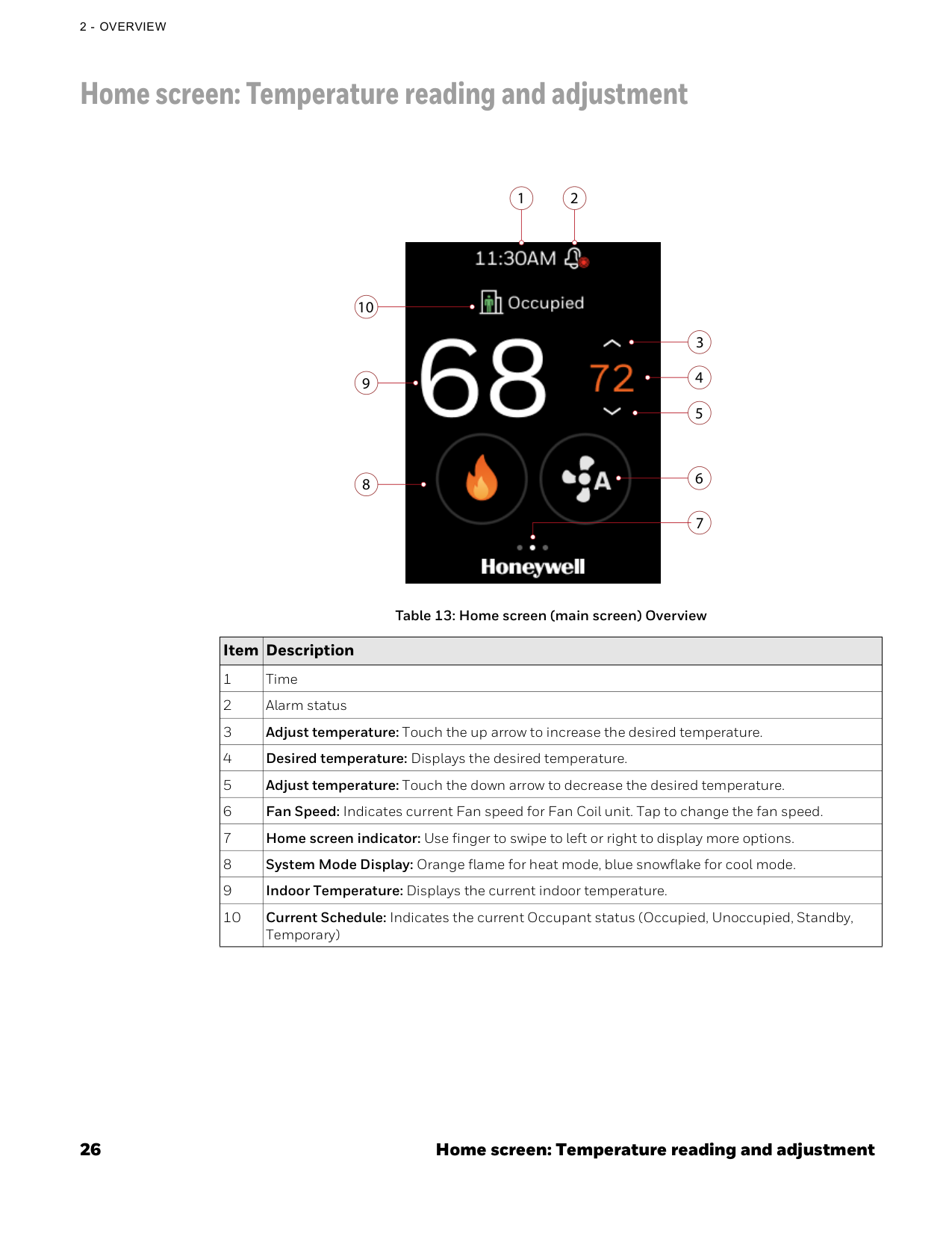
26 Home screen: Temperature reading and adjustment
2 - Overview
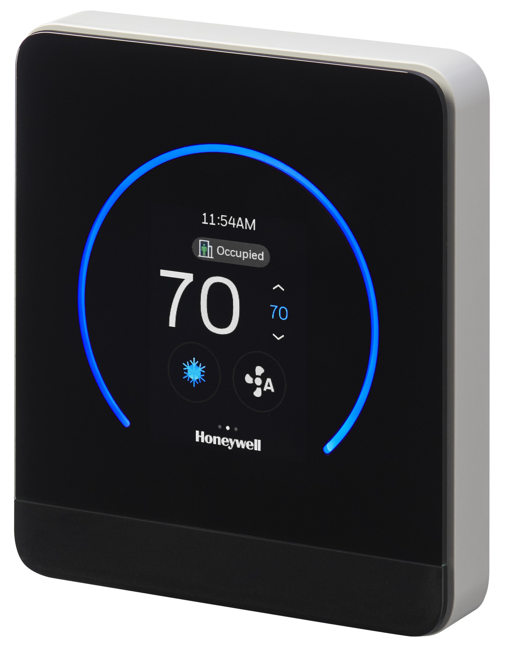
Home screen: Temperature reading and adjustment Table 13: Home screen (main screen) Overview Item Description 1 Time 2 Alarm status 3 Adjust temperature: Touch the up arrow to increase the desired temperature. 4 Desired temperature: Displays the desired temperature. 5 Adjust temperature: Touch the down arrow to decrease the desired temperature. 6 Fan Speed: Indicates current Fan speed for Fan Coil unit. Tap to change the fan speed. 7 Home screen indicator: Use finger to swipe to left or right to display more options. 8 System Mode Display: Orange flame for heat mode, blue snowflake for cool mode. 9 Indoor Temperature: Displays the current indoor temperature. 10 Current Schedule: Indicates the current Occupant status (Occupied, Unoccupied, Standby, Temporary) 10 9 8 1 3 4 5 7 6 2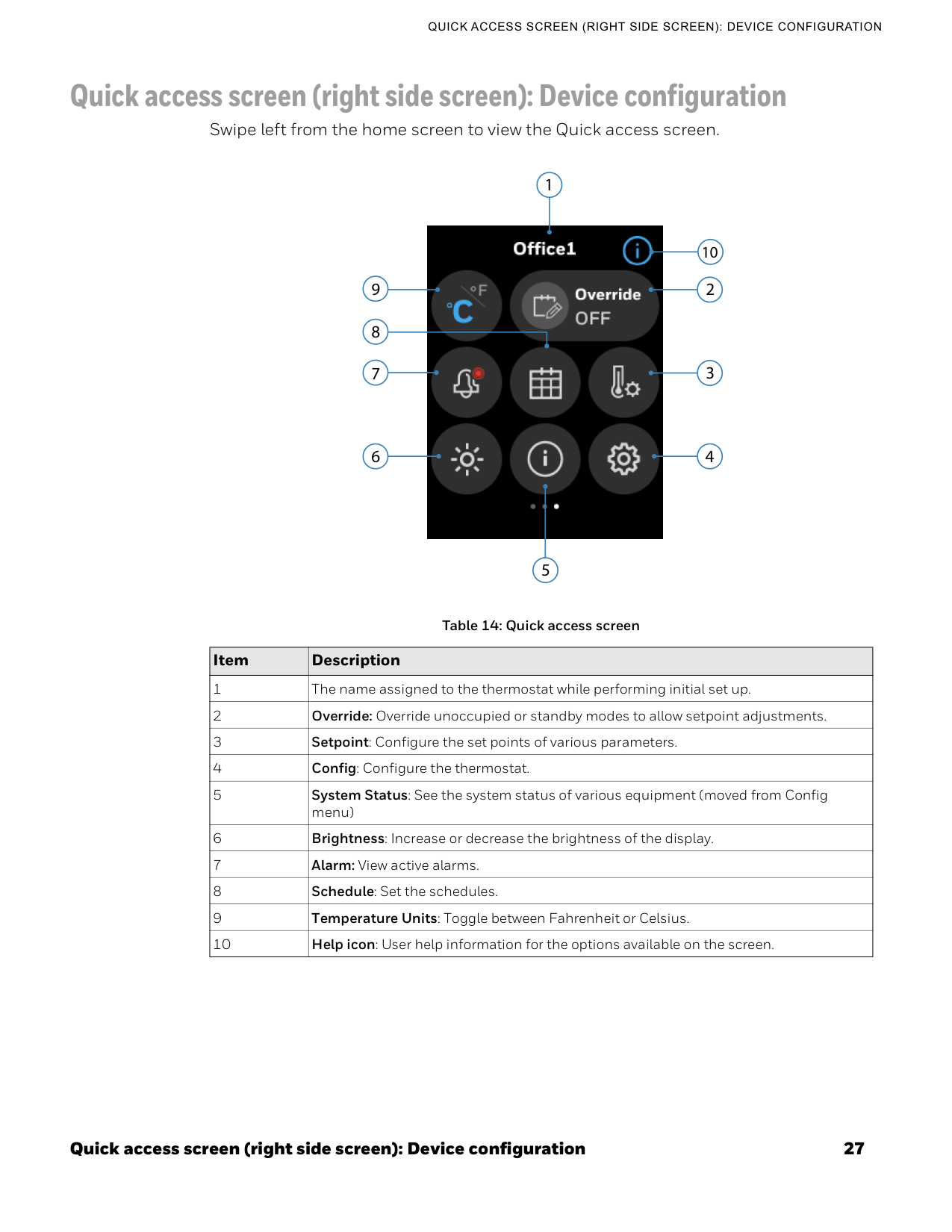
Quick access screen (right side screen): Device configuration 27
Quick Access Screen (Right Side Screen): Device Configuration
Quick access screen (right side screen): Device configuration Swipe left from the home screen to view the Quick access screen. Table 14: Quick access screen Item Description 1 The name assigned to the thermostat while performing initial set up. 2 Override: Override unoccupied or standby modes to allow setpoint adjustments. 3 Setpoint: Configure the set points of various parameters. 4 Config: Configure the thermostat. 5 System Status: See the system status of various equipment (moved from Config menu) 6 Brightness: Increase or decrease the brightness of the display. 7 Alarm: View active alarms. 8 Schedule: Set the schedules. 9 Temperature Units: Toggle between Fahrenheit or Celsius. 10 Help icon: User help information for the options available on the screen. 6 7 4 3 9 1 2 5 8 10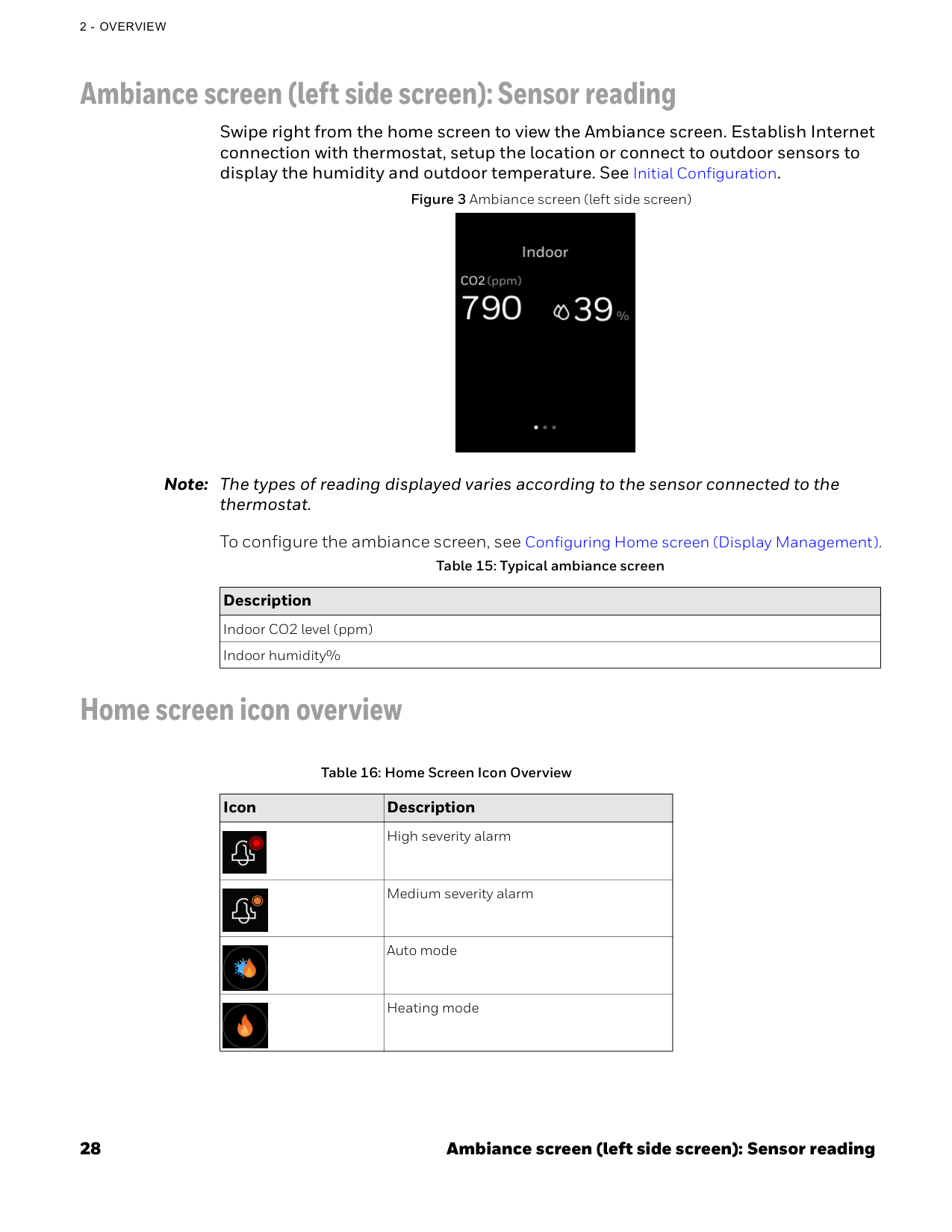
28 Ambiance screen (left side screen): Sensor reading
2 - Overview
Ambiance screen (left side screen): Sensor reading Swipe right from the home screen to view the Ambiance screen. Establish Internet connection with thermostat, setup the location or connect to outdoor sensors to display the humidity and outdoor temperature. See Initial Configuration. Figure 3 Ambiance screen (left side screen) Note: The types of reading displayed varies according to the sensor connected to the thermostat. To configure the ambiance screen, see Configuring Home screen (Display Management). Home screen icon overview Table 15: Typical ambiance screen Description Indoor CO2 level (ppm) Indoor humidity% Table 16: Home Screen Icon Overview Icon Description High severity alarm Medium severity alarm Auto mode Heating mode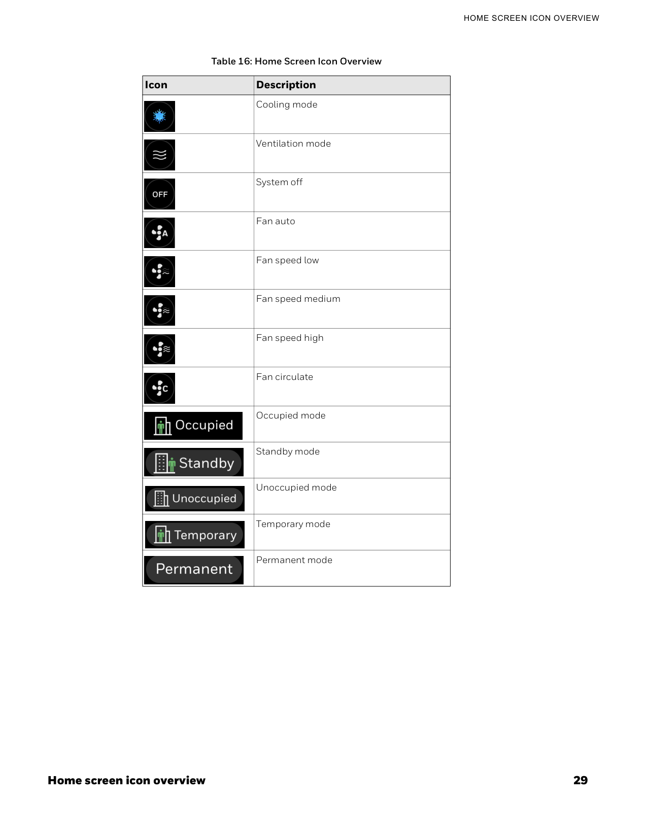
Home screen icon overview 29
Home Screen Icon Overview
Cooling mode Ventilation mode System off Fan auto Fan speed low Fan speed medium Fan speed high Fan circulate Occupied mode Standby mode Unoccupied mode Temporary mode Permanent mode Table 16: Home Screen Icon Overview Icon Description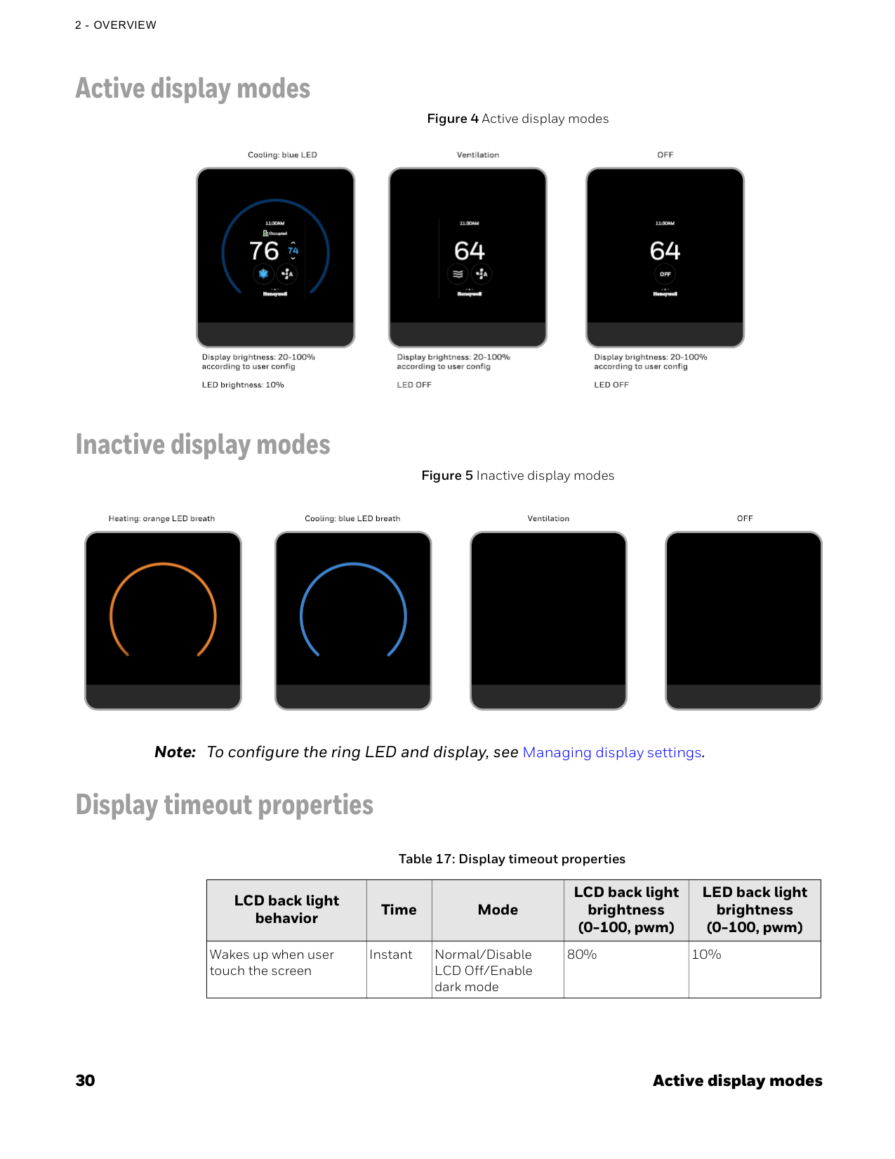
30 Active display modes
2 - Overview
Active display modes Figure 4 Active display modes Inactive display modes Figure 5 Inactive display modes Note: To configure the ring LED and display, see Managing display settings. Display timeout properties Table 17: Display timeout properties LCD back light behavior Time Mode LCD back light brightness (0-100, pwm) LED back light brightness (0-100, pwm) Wakes up when user touch the screen Instant Normal/Disable LCD Off/Enable dark mode 80% 10%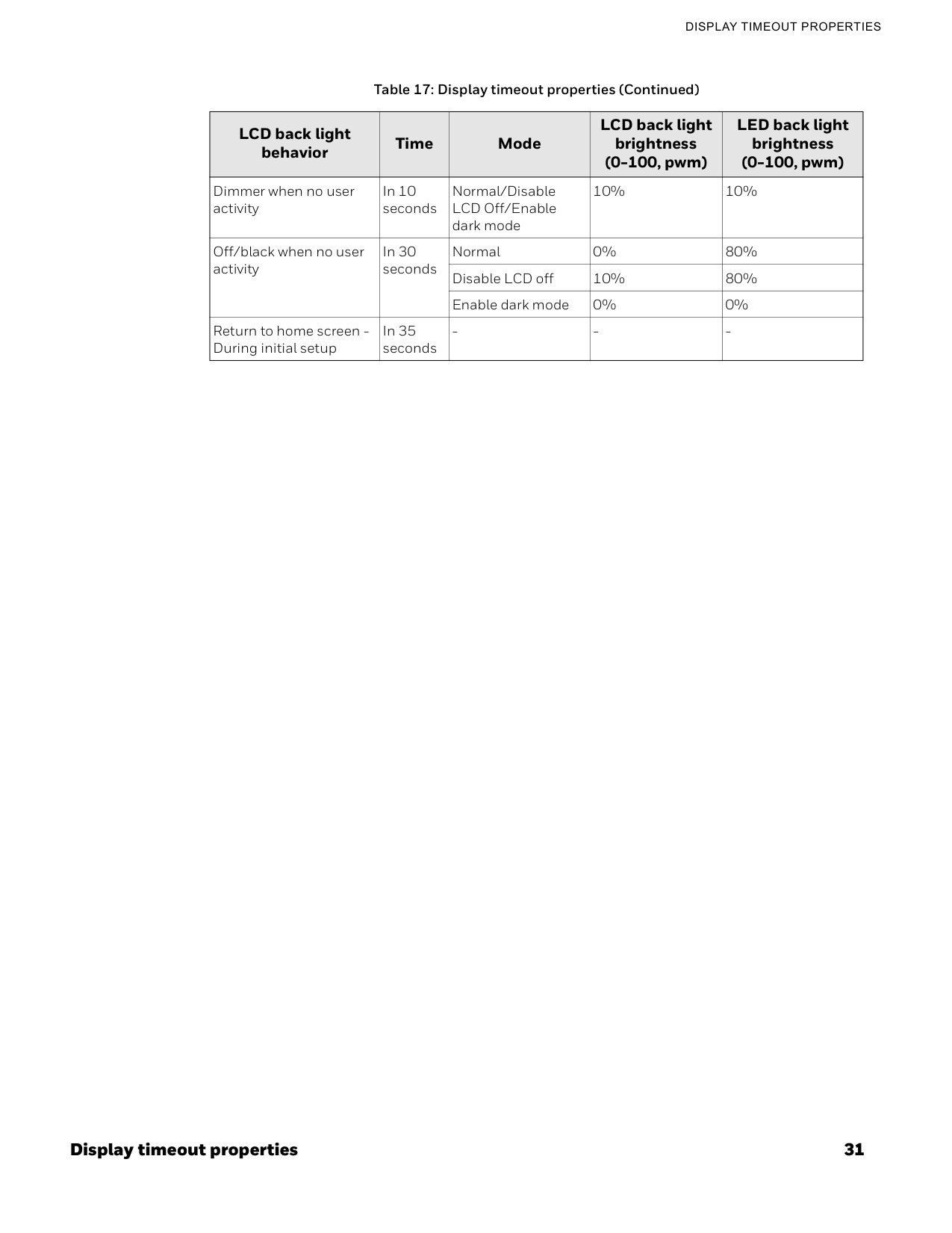
Display timeout properties 31
Display Timeout Properties
Dimmer when no user activity In 10 seconds Normal/Disable LCD Off/Enable dark mode 10% 10% Off/black when no user activity In 30 seconds Normal 0% 80% Disable LCD off 10% 80% Enable dark mode 0% 0% Return to home screen - During initial setup In 35 seconds
32 Display timeout properties
2 - Overview

Chapter
3 33 Getting Started This chapter contains steps and descriptions to set up the initial configuration of the thermostat and other basic configurations. Related topics Prerequisites Boot-up the thermostat
34 Prerequisites
3 - Getting Started
Prerequisites Before going through initial guided setup sequences, ensure the TC300 is installed and wired up according to the TC300 installation and mounting guide.Warnings
• To reduce the risk of electrical shock do not open the thermostat. There are no user- serviceable parts inside. Refer servicing to qualified service personnel only. • Cleaning — Use a dry cloth to clean the product. Do not use liquid cleaners or aerosol cleaners • Water and moisture — Do not use the product near water. Do not install the product in a place where water may splash onto it. • Do not operate the thermostat with a hard, sharp, or pointed object such as a fingernail, pen. • The screen used for the thermostat is made of glass. Therefore, it can break when the product is dropped or heavy impact is applied. Do not handle broken glass without appropriate protection in event of damage.
Boot-up the thermostat 35
Boot-Up The Thermostat
Boot-up the thermostat The thermostat will be powered up automatically after it mounted on the wallplate. You will navigate through the settings given below subsequently while setting up the thermostat. Assigning a name to the thermostat Connecting to network Selecting a temperature unit Setting Date and Time Setting up the Equipment type Setting up the System switch Configuring the Schedule Setting up the Installer Passcode Configuring the Service Info To set up the thermostat
36 Boot-up the thermostat
3 - Getting Started
Figure 5 Welcome screen
Boot-up the thermostat 37
Boot-Up The Thermostat
Connecting to network Figure 7 Connection
38 Boot-up the thermostat
3 - Getting Started
Selecting a temperature unit Figure 9 Temperature unit
Boot-up the thermostat 39
Boot-Up The Thermostat
Setting up the Equipment type The TC300 is designed to control Fan coil units. It can control 4 pipe dual coil, 4 pipe single coil, and 2 pipe single coil. Figure 11 Equipment and I/O
40 Boot-up the thermostat
3 - Getting Started

Boot-up the thermostat 41
Boot-Up The Thermostat
Configuration. Configuring the Service Info Figure 15 Service Info
42 Boot-up the thermostat
3 - Getting Started
Figure 17 User management
Chapter
4 43 Configuration This chapter contains thermostat level configuration and equipment level configuration procedures. Only the Installer has access to these configuration screens. Related topics Configuration screen Basic configuration Equipment configuration I/O terminal assignment Configuring sensors Managing System switch Managing Discharge air control Managing Dehumidification Managing Valve cycle Advanced configuration Managing Setpoint options Managing Cooling options Managing Heating options Managing Pipe sensor thresholds Managing Valve purge Miscellaneous Managing Service mode Managing Standby action Viewing the Security log Viewing the Diagnostics Managing connection User management Configuring the user roles
44 Configuration screen
4 - Configuration
Configuring Home screen (Display Management) Managing display settings Reset to default Viewing the system status Managing Setpoints Changing the system mode Changing the fan speed Configuration screen The configuration screen displays all the configuration items of the thermostat and equipment.
Basic configuration 45
Basic Configuration
Basic configuration The Basic Configuration includes options to configure the thermostat setting such as Device Name, Date and Time, Screen Cleaning, Override Setting, and Service Info. You might have configured these configurations while setting up the thermostat. However, you can change the configuration here again. Figure 20 Basic configuration The following features are covered under the Basic configuration. To rename the device name To configure Date & Time To enable screen cleaning mode To configure override setting To modify service info To rename the device name
46 Basic configuration
4 - Configuration
Figure 21 Naming the thermostat
Basic configuration 47
Basic Configuration

48 Basic configuration
4 - Configuration
Figure 24 Override setting
Equipment configuration 49
Equipment Configuration
Figure 26 Service information
50 Equipment configuration
4 - Configuration
Figure 27 Equipment screen To configure equipment and I/O
Equipment configuration 51
Equipment Configuration
Figure 29 Equipment and I/O types To configure the type of the equipment TC300 thermostat provides options to control three equipment types such as 4-pipe dual coil, 4-pipe single coil, and 2-pipe single coil. Here, you configure the cooling valve, heating valve types, floating and modulating controls. Figure 30 Equipment type
52 Equipment configuration
4 - Configuration
4-Pipe Dual Coil
Equipment configuration 53
Equipment Configuration
4-Pipe Single Coil2-10V
Cooling Range • Configure Min Output for Cooling • Configure Max Output for Cooling • Tap the Info icon to view the minimum allowed deadband range Heating Range • Configure Min Output for Heating • Configure Max Output for Heating Reverse Exchange the heating range and cooling range0-10V
Cooling Range • Configure Min Output for Cooling • Configure Max Output for Cooling • Tap the Info icon to view the minimum allowed deadband range Heating Range • Configure Min Output for Heating • Configure Max Output for Heating Reverse Exchange the heating range and cooling range
54 Equipment configuration
4 - Configuration
If Output is set to 2-10 Vdc
Equipment configuration 55
Equipment Configuration
To configure the fan type
56 Equipment configuration
4 - Configuration
Figure 32 Sensors
I/O terminal assignment 57
I/O Terminal Assignment

58 I/O terminal assignment
4 - Configuration
Figure 35 Terminals • Based on selected equipment function the terminals will be pre-assigned. To override default terminal assignment select alternate(s) as required. • If a terminal is assigned incorrect, then there will be a red box around the terminal button. Reassign the terminal. Figure 36 Incorrect terminal assignment • If the same terminal is assigned to two different functions, the user must resolve the conflict by reassigning the terminal. • In the below example, user tried to assign UIO1 to Medium speed fan. But the terminal is already assigned to Drain pan sensor. To resolve this issue, tap the Resolve Conflict button. It opens the Drain pan sensor screen. Reassign the terminal for Drain pan sensor
Configuring sensors 59
Configuring Sensors
Figure 37 Discard message
60 Configuring sensors
4 - Configuration
Figure 39 Sensors screen
Configuring sensors 61
Configuring Sensors
Figure 40 Sylk devices Note: The total number of Sylk Devices is restricted by Power and Communication bandwidth. In general, the number of Sylk devices cannot exceed the allowed limit. Contact the Honeywell Technical Support team for additional support.Tr40
Tr40-H
Tr40-Co2
Tr40-H-
Co2
Tr50-3N
Tr50-3D
Note: Set the red colored switches to the position as shown in the above image 3 Sylk Temperature sensorTr40
4 Sylk Temperature sensorTr40
5 Sylk Temperature sensorTr40

62 Configuring sensors
4 - Configuration
C7400S
Table 22: Sylk device dip switches Sylk Address Device Type Sensors DIP Switches
Configuring sensors 63
Configuring Sensors
Figure 42 Offset screens for temperature and humidity Note: These offsets should be used only when measured temperature or humidity is verified with calibrated sensor located in same location.
64 Managing System switch
4 - Configuration
To configure Control sensors The thermostat groups the control sensors into three types. There are Local sensor, Remote sensor, and Multi sensor. Local Sensor: Internal TC300 temperature sensor. Installer can configure offsets to on-board temperature and humidity sensors, if desired. Remote Sensor: Space temperature sensor connected to UI/UIO terminal, or TR40 sensor configured at address 2. Multi Sensor: Local Sensor and Sylk sensors at address 2, 3, 4, 5 used together to calculate space temperature.
Managing Discharge air control 65
Managing Discharge Air Control
Figure 44 System switch
66 Managing Discharge air control
4 - Configuration

Managing Dehumidification 67
Managing Dehumidification
Figure 47 On-screen help Managing Dehumidification Dehumidification function will maintain humidity below programmed setpoint using onboard humidity sensor. For systems without reheat the dehumidification function will allow cooling below the target setpoint based on programmed over cool offset. If humidity threshold cannot be achieved once lower space temperature threshold has been reached the dehumidification function will be suspended. For applications with reheat function setpoint will be maintained during dehumidification cycle by activating reheat using heating coil or via auxiliary heat (electric heat). To configure dehumidification
68 Managing Valve cycle
4 - Configuration
Figure 48 Dehumidification Note: The Reheat option is applicable only for 4-pipe dual coil. Aux Heat for Reheat is applicable for both 4- pipe single coil and 2-pipe single coil.
Advanced configuration 69
Advanced Configuration
Figure 49 Valve cycle Advanced configuration The Advanced configuration screen displays all the advanced options of the thermostat. To view Advanced options
70 Managing Setpoint options
4 - Configuration
Figure 50 Advanced configuration Managing Setpoint options This option allows users to set the maximum or minimum temperature setpoints. To configure setpoint options
Managing Setpoint options 71
Managing Setpoint Options
Figure 51 Setpoint options Table 23: Setpoint options Operation Configuration Type Range Description Stops Cooling Min. Setpoint 50-99°F (Default50°F)
The minimum cool setpoint that can be set by the user Heating Max. Setpoint 40-105°F (Default90°F)
The maximum heat setpoint can be set by the user Limits Thermostat Deadband 2°F-8°F(Default: 3°F) Ensures that the heat setpoint and the cool setpoint maintain a differential minimum temperature span the thermostat is in auto mode. Temporary Setpoint Limit 0°F - 45°F (Default30°F)
The range above or below occupied setpoint by which the temperature may be altered by user from programmed scheduled setpoint in occupied state or when initiating temporary override of schedule. This includes scheduled occupancy or override of the scheduled occupancy (bypass override). During unoccupied and standby periods, the effective setpoint offset is set to 0 Δ°F. If an occupant wants to change the temporary setpoint, the occupant must first override the schedule to occupied and then the thermostat will allow the occupant to change the temporary setpoint
72 Managing Cooling options
4 - Configuration
Managing Cooling options To configure cooling options
Managing Cooling options 73
Managing Cooling Options
Figure 52 Cooling options Table 24: Cooling options Cooling type Configuration Type Range Description DAT Limit DAT Cooling Low Limit -40 to 60°F (Default 45°F) When the discharge air temperature is below the discharge air low limit setpoint, the cooling control will turn off cooling physical output until the discharge air temperature rises above it's setpoint +2 °F differential. Gains Throttling Range 0 to 30°F (Default 4°F) The throttling range is the amount of change in the sensed temperature required to drive the output from 0 to 100%. The throttling range must be narrow enough to provide good control without becoming unstable. The throttling range is determined by factors including: the control application, heating or cooling capacity of the equipment relative to the physical size of the space being controlled, and the control algorithm being used. The narrower (smaller) the throttling range, the more precise the control and the wider (larger) the throttling range, the more stable the control. The objective is setting the throttling range to achieve the optimum balance between precision and stability. Cooling Integral Time 0 to 5000 Sec Default 2500 Sec The amount of time the error has continued uncorrected. Integral action corrects the temperature control errors of proportional-only control, but it is slower to react to large temperature or setpoint changes. Fan Delay Fan Off Delay Time 0-180 Sec Fan run on time after all cooling outputs are turned off. May be used to run fan after all cooling outputs have turned off so that the cooling coil can warm up before the fan turns off to prevent condensation from evaporating into the space.
74 Managing Heating options
4 - Configuration
Managing Heating options To configure cooling options
Managing Pipe sensor thresholds 75
Managing Pipe Sensor Thresholds
Managing Pipe sensor thresholds This feature is suitable for heating when pipe temperature is above threshold, and suitable for Cooling when pipe temperature is below threshold. To configure Pipe sensor thresholds80°F)
When the pipe temperature is above the threshold, it is suitable for heating. Pipe Sensor Threshold for Cooling 45 to 65°F (Default60°F)
When the pipe temperature is below the threshold, it is suitable for cooling.
76 Managing Valve purge
4 - Configuration
Managing Valve purge This setting for 2-pipe systems cycles valve to ensure accurate changeover temperature sensor reading if there are infrequent heating or cooling cycles. To configure Valve purge5°F)
When the pipe temperature is above the space temperature and the hybrid control is enabled, than the offset is suitable for heating. Timeout Timer (Heat) 1 to 4 hours (Default 4 hours) When the configured timer expires, the pipe sensor reading is compared to the threshold setting, if the pipe sensor reading is above the threshold, it will generate water temperature. No heating alarm will be raised. Temp Offset (Cool) -10 to -5°F (Default-5°F)
When the pipe temperature is below the space temperature and the hybrid control is enabled, than the offset is suitable for cooling. Timeout Timer (Cool) 1 to 4 hours (Default 4 hours) When the configured timer expires, the pipe sensor reading is compared to the threshold setting, if the pipe sensor reading is below the threshold, it will generate water temperature. No cooling alarm will be raised. Table 26: Pipe sensor threshold (Continued) Operation Configuration Type Range Description
Miscellaneous 77
Miscellaneous
Miscellaneous To configure miscellaneous
78 Managing Service mode
4 - Configuration
Figure 57 Service mode enabling Based on terminal configuration, the following screen displays different options for manual testing. For example, in below screen, single speed fan, Heating equipments, Cooling floating, and Aux heat equipments are configured. Connect these test equipment to the relevant terminals and test for actual output. Figure 58 Service mode
Managing Standby action 79
Managing Standby Action
Figure 59 Typical service mode options
80 Viewing the Security log
4 - Configuration

Managing connection 81
Managing Connection
To view the Diagnostics
82 Managing connection
4 - Configuration

Managing connection 83
Managing Connection
Figure 67 Baud Rate
84 Managing connection
4 - Configuration

User management 85
User Management
User management The TC300 supports four kinds of user identities as identified in Table 27 with limited privileges as noted. Except for the Installer role these privileges can be reduced in the user settings menu. Passcode rules All the user accounts are passcode protected. When creating the passcode, follow the passcode rules given below. • Passcode length must be between 4 to 12 characters • Do not use spaces • Do not use the same passcode used for other users (across all user types) • If no passcode is entered for basic or Admin, the thermostat will remain at the highest level of access, installer, and will not require a passcode for access. Configuring the user roles To configure user management
86 Configuring the user roles
4 - Configuration
Figure 70 User management Visitor To view the Visitor user role
Configuring the user roles 87
Configuring The User Roles
Figure 72 Basic user permission.
88 Configuring Home screen (Display Management)
4 - Configuration
Figure 74 Admin user permission.
Managing display settings 89
Managing Display Settings
Figure 76 Display management All icons are enabled by default. You can turn it off by sliding the toggle button to the left.
90 Managing display settings
4 - Configuration
The Display Settings screen appears. Figure 78 Display settings

Reset to default 91
Reset To Default
Figure 80 Inactive display
92 Viewing the system status
4 - Configuration
Figure 82 Weekly reset and confirmation messageThe System status screen appears.

Managing Setpoints 93
Managing Setpoints
Figure 84 System status Managing Setpoints To configure setpoint settings
94 Managing Setpoints
4 - Configuration
Figure 85 Quick access screenThe Setpoint screen appears. Figure 86 Define the setpoints

Changing the system mode 95
Changing The System Mode
The Mode screen appears. Figure 88 System mode

96 Changing the fan speed
4 - Configuration
Changing the fan speed To change the fan speedThe Fan Speed screen appears. Figure 89 Fan speed

Chapter
5 Alarms 97 Alarms This chapter explains alarms and their configuration procedures. Related topics Alarms Alarm notification signs Alarm notification Alarm preference Unacknowledged alarms List of alarms and their severity Managing the alarms Alarms In the TC300 thermostat, alarms are configured for predefined set values. When the values are breached, the alarms are triggered and displayed on the home screen as banner notification, dot notification, and on the Alarm button. You can view the triggered alarms and acknowledge them. Alarm notification signs The alarm menu notification icon has two color codes to indicate the severity of the alarm. The following table describes the available signs with color codes of the alarm screens. Icons Description High Medium
98 Alarm notification
5 - Alarms
Alarm notification The alarms can be configured as banner notification or dot notification as per the alarm configuration. The banner notification is pop-up on the home screen whereas the dot notification appears beside the time. For alarm configuration, refer to Configuring the alarm preference. Figure 91 Alarm banner notification You can tap the banner notification to view the alarm and acknowledge it. If multiple alarms are triggered then the latest one (high) will be displayed on the home screen. After tapping the banner, it takes you to the Alarm screen. • High - Red color banner • Medium - Orange color banner Alarm preference To create alarm preference
Alarm preference 99
Alarm Preference
Figure 93 Alarm types
100 Alarm preference
5 - Alarms
Figure 94 Alarm configuration screen Alarm reason description is displayed on the screen.
Unacknowledged alarms 101
Unacknowledged Alarms

102 Unacknowledged alarms
5 - Alarms
Figure 98 Alarm preference - Alarm
List of alarms and their severity 103
List Of Alarms And Their Severity
Figure 100 Alarm detail
104 List of alarms and their severity
5 - Alarms
Pipe Sensor Out of Range High Water Temperature is Not Suitable for Heating/Cooling High Room Temperature Changing Trend is Reversed with System Mode High Unknown Time Medium Alarms Severity
Managing the alarms 105
Managing The Alarms
Managing the alarmsS.N0
Alarm Trigger Scenario Action Level 1 Proof of Air Flow Alarm (fan state) An input (e.g., a current switch or differential pressure switch) should be available to monitor proof of air flow in the Fan Coil Unit. When configured, the control system will check this digital input once per second. If the fan is supposed to be on but is not, an alarm should be generated. For example, users can configure a DIO/UIO terminal as a binary input to detect the fan's status. When DIO2 is set as the Fan Command, and the device sets DIO2 to 'on,' if the digital input indicates no air flow for 60 consecutive seconds, a 'Proof of Air Flow' alarm will be triggered. Depending on the alarm configuration:
106 Managing the alarms
5 - Alarms
5 Space Temperature Sensor FailureS.N0
Alarm Trigger Scenario Action Level
Managing the alarms 107
Managing The Alarms
10 Water temperature is not suitable for Heating/ Cooling Applicable only for Dual-Pipe FCU Heating/Cooling Systems.S.N0
Alarm Trigger Scenario Action Level
108 Managing the alarms
5 - Alarms

Chapter
6 About Schedule 109 Scheduling About Schedule TC300 enables you to plan operations based on the time of day and holidays. This scheduling structure allows you to control day-to-day operations with the standard schedule. The holiday schedule controls days or times when a facility is typically unoccupied. The event schedule controls periods outside normal occupied times. The holiday schedule overrides the standard schedule and the event schedule overrides the holiday and standard schedules within a schedule set. Schedules use the setpoint configuration of Occupied, Unoccupied, or Standby modes. Occupied mode treats the building space as occupied and configured with comfort setpoints. Unoccupied mode treats the building space as not occupied and configured with energy savings setpoints. Standby mode setpoints are configured in a way that the setpoints can quickly change to the Occupied mode when switched. Standby mode setpoint saves energy higher than occupied mode and lesser than the Unoccupied mode. Temporary mode allows the user to change the temperature setpoints of the Occupied mode after the user switches to the temporary mode from the Occupied mode. This is not possible in Unoccupied mode and Standby mode. When a schedule uses the Occupied mode but the Occupancy sensor reads unoccupied, then the thermostat switches automatically to the Standby mode. In other scenarios, the thermostat follows the schedule status and the occupancy sensor’s value has no impact on it. How schedules works When you set up schedules, it is important to understand the relationship of the schedules in the schedule set and how to use each one. • Standard schedule: Use the weekly schedule to program occupied and standby periods for each of the week. • Holiday schedule: Use holiday schedules to set holidays that “float” or occur on a specific date each year. Up to 10 holidays can be created.
110 Setting up a weekly schedule
6 - Scheduling
• Special event: Use Special event to create up to 10 special events. Note: Holiday schedules automatically write a 12:00 AM OFF time, which is in effect unless it is overridden by an event schedule. Related topics Setting up a weekly schedule Setting up a holiday schedule Special event Setting up a weekly schedule To add a new time value to a weekly schedule
Setting up a weekly schedule 111
Setting Up A Weekly Schedule

112 Setting up a weekly schedule
6 - Scheduling

Setting up a weekly schedule 113
Setting Up A Weekly Schedule
Editing or deleting weekly schedules The existing weekly schedules can be edited from the Weekly schedule screen. To change or delete an existing weekly schedule
114 Setting up a weekly schedule
6 - Scheduling
Copying the schedules from one day to another The TC300 enables the user to copy an existing regular schedule. To copy a schedule from one day to another
Setting up a holiday schedule 115
Setting Up A Holiday Schedule
Figure 111 Copy successful Setting up a holiday schedule Holidays are defined as reoccurring events that are different from the weekly schedule, can be Occupied or Standby, or by default Unoccupied. So the Unoccupied/Standby mode setpoints will be executed on the holidays. There are two holiday types are available to choose. There are Floating date and Specific date. Only one day can be selected for the floating holiday type whereas multiple days can be selected for Specific date type. To schedule a holiday
116 Setting up a holiday schedule
6 - Scheduling
Figure 113 Schedule types
Setting up a holiday schedule 117
Setting Up A Holiday Schedule
Figure 116 Set Date
118 Setting up a holiday schedule
6 - Scheduling
Figure 118 Create holiday vent screen
Setting up a holiday schedule 119
Setting Up A Holiday Schedule
Editing or deleting Holiday The existing weekly Holidays can be edited from the Holiday screen. To change or delete an existing holiday
120 Setting up a holiday schedule
6 - Scheduling
Copying the Holiday events from one day to another The TC300 enables the user to copy an existing holidays. To copy a schedule from one day to another
Special event 121
Special Event
Figure 122 Copy successful Special event Special events are one time events that are different from the weekly schedule. To create a special event
122 Special event
6 - Scheduling
Figure 124 Create special event
Special event 123
Special Event
Figure 126 Adding new event
124 Special event