
Ask AI
— answers from the official manualAnswers from the official manual.
Common questions
Common Questions
24 totalHow do I reset the boiler after a fault has occurred?
Press the up and down arrow keys simultaneously until the fault symbols H and ! are no longer displayed. The appliance will then start up again and the flow temperature will be displayed. If the fault cannot be eliminated after resetting, contact an Installer/Service Engineer or Worcester, Bosch Group on 0330 123 9339. (Page 14)
What should I do if the condensate pipe freezes during cold weather?
Locate the blockage, which is likely at the most exposed point outside the building, and thaw it using a hot water bottle, microwaveable heating pack, or a cloth soaked in hot water — do not use boiling water as it can damage plastic pipes. After thawing, reset the appliance and wait two or three minutes for it to restart. If the boiler does not restart, contact Worcester, Bosch Group on 0330 123 9339. (Page 14)
What is the difference between comfort mode and ECO mode for hot water?
In comfort mode, the appliance continuously maintains water at the set temperature, resulting in a shorter wait for hot water but higher gas usage. In ECO mode, the appliance only begins heating water once the hot tap is opened, saving gas but with a slightly longer wait. To set ECO mode, press the eco key until 'eco' appears in the display; press it again to return to comfort mode. (Page 11)
What is the correct system pressure for the Greenstar 1000 and how do I check it?
The system pressure should be adjusted to between 1.3 and 1.7 bar. You can check the system pressure via the HMI screen by pressing the return button or the up/down arrows. If the pressure reads less than 0.8 bar, you should re-charge the system. (Page 6)
What should I do if I smell gas?
Do not operate any electrical switches, use a lighter, smoke, or use the telephone. Turn off the gas at the meter, open windows and doors, warn your neighbours, leave the building, and call the National Gas Emergency Service on 0800 111 999. For LPG boilers, call the supplier's number on the side of the gas tank. (Page 4)
How do I set the boiler to ECO mode for hot water?
Press the eco key until 'eco' appears in the display to activate ECO mode. In ECO mode, heating up to the set temperature begins as soon as the hot water tap has been opened, rather than continuously maintaining temperature as in comfort mode. To return to comfort mode, press the eco key until 'eco' vanishes from the display. (Page 11)
Show 18 more questions
How often should the Greenstar 1000 be serviced?
What should I do if my condensate pipe freezes in cold weather?
How do I activate Manual Mode on the Greenstar 1000?
How do I check the system pressure on my Greenstar 1000 boiler?
What should I do if the boiler display shows a low pressure indication (LOPR)?
How do I re-pressurise my heating system using the external filling loop?
What is the Quick Tap function and how do I use it?
How do I set the flow temperature on my Greenstar 1000?
What is the difference between comfort mode and ECO mode for DHW heating?
What does Fault 2980 mean and what should I do?
What should I do if the condensate pipe has frozen?
How often should my Greenstar 1000 boiler be serviced?
What are the minimum clearances required around the Greenstar 1000 for servicing?
What should I do if I see fault code 2980 on the display?
How do I re-pressurise the heating system using the external filling loop?
How do I set the boiler to Summer Mode?
How often should the Greenstar 1000 be serviced, and who should carry it out?
What is the maximum flow temperature range I can set, and is there a scalding risk?
Full Manual
19 pages
6721835944 (2023/08) Uk
User Instructions Gas-fired condensing combi appliance Greenstar 1000Gr1000W 24 C Ng | Gr1000W 30 C Ng
Preface Greenstar 1000 – 6721835944 (2023/08) 2 Preface Dedicated to heating comfort. Thank you for purchasing a Worcester product. We pride ourselves on manufacturing products to the strictest quality control standards throughout every stage of production. Worcester, Bosch group has led the field in innovative product design and performance for over 50 years. This heritage means all our products are of exceptional quality and proven reliability. Our products employ the latest technologies and they are reliable, extremely energy efficient, offering you economical running costs and value for money. They are amongst the top energy rated products available. There is also the reassurance of our parts and labour guarantee. Our Customer Service team is here to help you get the best from your Worcester product throughout its lifetime. Whatever your enquiry, our specially trained team is available at our Worcester based contact centre and online via the website. For contact details see the back cover.
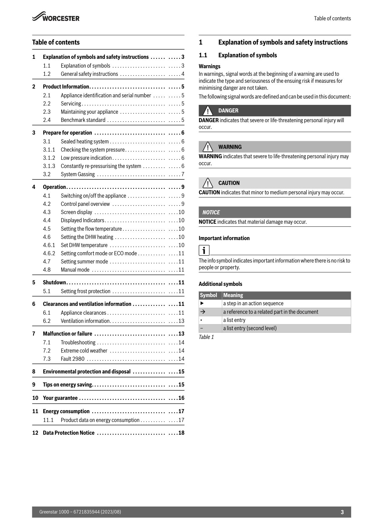
Table of contents 3 Greenstar 1000 – 6721835944 (2023/08) Table of contents 1 Explanation of symbols and safety instructions 1.1 Explanation of symbols Warnings In warnings, signal words at the beginning of a warning are used to indicate the type and seriousness of the ensuing risk if measures for minimising danger are not taken. The following signal words are defined and can be used in this document:
Danger
DANGER indicates that severe or life-threatening personal injury will occur.Warning
WARNING indicates that severe to life-threatening personal injury may occur.Caution
CAUTION indicates that minor to medium personal injury may occur.Notice
NOTICE indicates that material damage may occur. Important information The info symbol indicates important information where there is no risk to people or property. Additional symbols Table 1 1 Explanation of symbols and safety instructions . . . . . . . . . . . 3 1.1 Explanation of symbols . . . . . . . . . . . . . . . . . . . . . . . . . . 3 1.2 General safety instructions . . . . . . . . . . . . . . . . . . . . . . . 4 2 Product Information. . . . . . . . . . . . . . . . . . . . . . . . . . . . . . . . . . . 5 2.1 Appliance identification and serial number . . . . . . . . . . 5 2.2 Servicing. . . . . . . . . . . . . . . . . . . . . . . . . . . . . . . . . . . . . . 5 2.3 Maintaining your appliance . . . . . . . . . . . . . . . . . . . . . . . 5 2.4 Benchmark standard . . . . . . . . . . . . . . . . . . . . . . . . . . . . 5 3 Prepare for operation . . . . . . . . . . . . . . . . . . . . . . . . . . . . . . . . . 6 3.1 Sealed heating system . . . . . . . . . . . . . . . . . . . . . . . . . . . 6 3.1.1 Checking the system pressure. . . . . . . . . . . . . . . . . . . . . 6 3.1.2 Low pressure indication. . . . . . . . . . . . . . . . . . . . . . . . . . 6 3.1.3 Constantly re-pressurising the system . . . . . . . . . . . . . . 6 3.2 System Gassing . . . . . . . . . . . . . . . . . . . . . . . . . . . . . . . . 7 4 Operation. . . . . . . . . . . . . . . . . . . . . . . . . . . . . . . . . . . . . . . . . . . . 9 4.1 Switching on/off the appliance . . . . . . . . . . . . . . . . . . . . 9 4.2 Control panel overview . . . . . . . . . . . . . . . . . . . . . . . . . . 9 4.3 Screen display . . . . . . . . . . . . . . . . . . . . . . . . . . . . . . . .10 4.4 Displayed Indicators. . . . . . . . . . . . . . . . . . . . . . . . . . . .10 4.5 Setting the flow temperature. . . . . . . . . . . . . . . . . . . . .10 4.6 Setting the DHW heating . . . . . . . . . . . . . . . . . . . . . . . .10 4.6.1 Set DHW temperature . . . . . . . . . . . . . . . . . . . . . . . . . .10 4.6.2 Setting comfort mode or ECO mode . . . . . . . . . . . . . . .11 4.7 Setting summer mode . . . . . . . . . . . . . . . . . . . . . . . . . .11 4.8 Manual mode . . . . . . . . . . . . . . . . . . . . . . . . . . . . . . . . .11 5 Shutdown. . . . . . . . . . . . . . . . . . . . . . . . . . . . . . . . . . . . . . . . . . .11 5.1 Setting frost protection . . . . . . . . . . . . . . . . . . . . . . . . .11 6 Clearances and ventilation information . . . . . . . . . . . . . . . . .11 6.1 Appliance clearances . . . . . . . . . . . . . . . . . . . . . . . . . . .11 6.2 Ventilation information. . . . . . . . . . . . . . . . . . . . . . . . . .13 7 Malfunction or failure . . . . . . . . . . . . . . . . . . . . . . . . . . . . . . . .13 7.1 Troubleshooting . . . . . . . . . . . . . . . . . . . . . . . . . . . . . . .14 7.2 Extreme cold weather . . . . . . . . . . . . . . . . . . . . . . . . . .14 7.3 Fault 2980 . . . . . . . . . . . . . . . . . . . . . . . . . . . . . . . . . . .14 8 Environmental protection and disposal . . . . . . . . . . . . . . . . .15 9 Tips on energy saving. . . . . . . . . . . . . . . . . . . . . . . . . . . . . . . . .15 10 Your guarantee . . . . . . . . . . . . . . . . . . . . . . . . . . . . . . . . . . . . . .16 11 Energy consumption . . . . . . . . . . . . . . . . . . . . . . . . . . . . . . . . .17 11.1 Product data on energy consumption . . . . . . . . . . . . . .17 12 Data Protection Notice . . . . . . . . . . . . . . . . . . . . . . . . . . . . . . .18 Symbol Meaning ▶ a step in an action sequence a reference to a related part in the document • a list entry – a list entry (second level)
Explanation of symbols and safety instructions Greenstar 1000 – 6721835944 (2023/08) 4 1.2 General safety instructions HNotices for the target group These operating instructions are intended for the heating system operator. All instructions must be observed. Failure to comply with instructions may result in material damage and personal injury, including danger to life. ▶Read and retain the operating instructions (heat generator, heating controller, etc.) prior to operation. ▶Observe the safety instructions and warnings. ▶Operate the heat generator only with the casing fitted and closed. HDetermined use The product may only be used for the heating of boiler water and for DHW heating. Any other use is considered inappropriate. We assume no liability for damage occurring due to non-permitted use. HIf you smell gas A gas leak could potentially cause an explosion. If you smell gas, observe the following rules: ▶Prevent flames or sparks: – Do not smoke, use a lighter or strike matches. – Do not operate any electrical switches or unplug any equipment. – Do not use the telephone or ring doorbells. ▶Turn off the gas at the meter or regulator. ▶Open windows and doors. ▶Warn your neighbours and leave the building. ▶Prevent anyone from entering the building. ▶Move well away from the building: call the National Gas Emergency Service on 0800 111 999. ▶L.P.G. boilers: Call the supplier’s number on the side of the gas tank. HDanger to life from poisoning by flue gas There is a danger to life from escaping flue gas. ▶Never modify any parts through which flue gas is routed. If flues are damaged or leaking, or if you smell flue gas, observe the following rules. ▶Switch off the heat source. ▶Open doors and windows ▶Warn your neighbours and leave the building immediately. ▶Prevent third parties from entering the building. ▶Notify an approved contractor. ▶Have any defects rectified. HDanger to life from carbon monoxide Carbon monoxide (CO) is a poisonous gas, which arises during the incomplete combustion of fossil fuels such as oil, gas or solid fuels. Dangers arise, if carbon monoxide escapes from the heating system due to a fault or a leak and collects unnoticed in enclosed spaces. You can neither see, taste nor smell carbon monoxide. To avoid danger from carbon monoxide: ▶Have the heating system inspected and serviced regularly by an approved contractor. ▶Use a CO detector, which gives an alarm in good time if CO escapes. ▶If you suspect a CO leak: – Warn your neighbours and leave the building immediately. – Call an approved contractor. – Have any defects rectified. HInspection, cleaning and maintenance The user is responsible for ensuring the heating system is safe and environmentally compatible. Non-existent or improper inspection, cleaning and maintenance may result in personal injury, including danger to life or material damage. We recommend that you enter into a contract covering an annual inspection and responsive cleaning and maintenance with an approved contractor. ▶Have work carried out only by an approved contractor. ▶Have the appliance and heating system inspected by an approved contractor at least once a year. ▶Have any required cleaning or maintenance work carried out immediately. ▶Have any defects in the appliance and heating system remedied immediately, independent of the annual inspection. H Fittings and modification Only a competent engineer can remove the appliance case and carry out any work, in accordance with the relevant Installation Regulations. Any misuse or unauthorised modifications to the appliance, flue or associated accessories and heating system will invalidate the guarantee. ▶Do not modify the appliance or flue system in any way. Worcester, Bosch Group accepts no liability arising from any such actions. This does not affect your statutory rights. HCombustion air/ambient air The air in the installation location must be free of flammable or chemically aggressive substances. ▶Do not store or use any flammable or explosive materials (paper, petrol, thinners, paints, etc.) in the vicinity of the heat source. ▶Do not store or use any corrosive substances (solvents, adhesives, chlorinated cleaning agents, etc.) in the vicinity of the heat source. H General considerations ▶The boiler must be installed in a well ventilated area. The openings must be kept in good condition. ▶The vents or any other component contributing to the functioning of the boiler must not be reduced or sealed. ▶We recommend an annual service of the appliance by an approved engineer to ensure reliable and efficient operation. HSafety of electrical devices for domestic use and similar purposes The following requirements apply in accordance with EN 60335-1 in order to prevent hazards from occurring when using electrical appliances: “This appliance can be used by children of 8 years and older, as well as by people with reduced physical, sensory or mental capabilities or lacking in experience and knowledge, if they are supervised and have been given instruction in the safe use of the appliance and understand the resulting dangers. Children shall not play with the appliance. Cleaning and user maintenance must not be performed by children without supervision.” “If the power cable is damaged, it must be replaced by the manufacturer, its customer service department or a similarly qualified person, so that risks are avoided.” H Please read these instructions carefully ▶These instructions are applicable to the Worcester appliance model/ s stated on the front cover only. ▶These instructions apply in the UK/IE only and must be followed except for any statutory obligation.
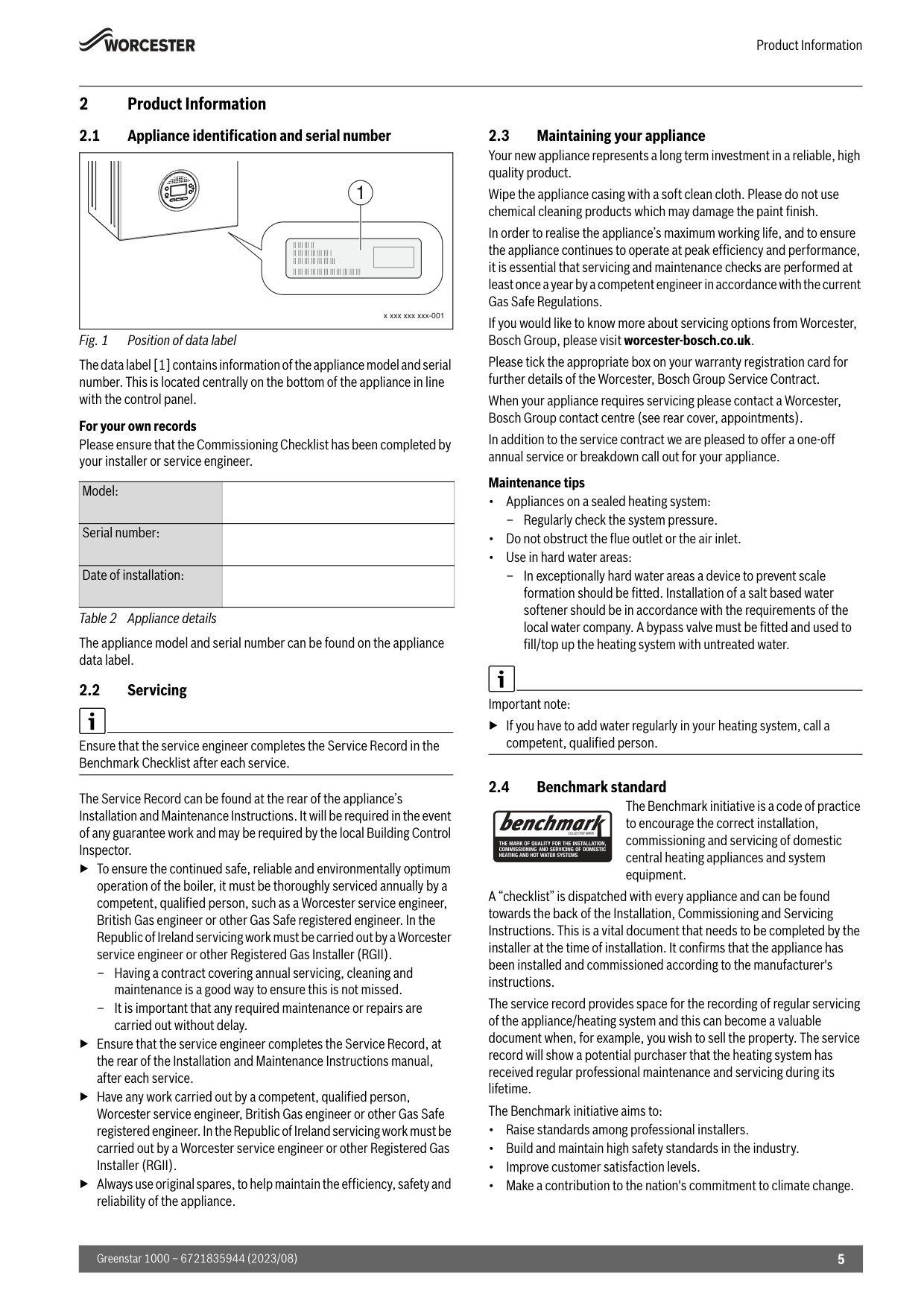
Product Information 5 Greenstar 1000 – 6721835944 (2023/08) 2 Product Information 2.1 Appliance identification and serial number Fig. 1 Position of data label The data label [1] contains information of the appliance model and serial number. This is located centrally on the bottom of the appliance in line with the control panel. For your own records Please ensure that the Commissioning Checklist has been completed by your installer or service engineer. Table 2 Appliance details The appliance model and serial number can be found on the appliance data label. 2.2 Servicing Ensure that the service engineer completes the Service Record in the Benchmark Checklist after each service. The Service Record can be found at the rear of the appliance’s Installation and Maintenance Instructions. It will be required in the event of any guarantee work and may be required by the local Building Control Inspector. ▶To ensure the continued safe, reliable and environmentally optimum operation of the boiler, it must be thoroughly serviced annually by a competent, qualified person, such as a Worcester service engineer, British Gas engineer or other Gas Safe registered engineer. In the Republic of Ireland servicing work must be carried out by a Worcester service engineer or other Registered Gas Installer (RGII). – Having a contract covering annual servicing, cleaning and maintenance is a good way to ensure this is not missed. – It is important that any required maintenance or repairs are carried out without delay. ▶Ensure that the service engineer completes the Service Record, at the rear of the Installation and Maintenance Instructions manual, after each service. ▶Have any work carried out by a competent, qualified person, Worcester service engineer, British Gas engineer or other Gas Safe registered engineer. In the Republic of Ireland servicing work must be carried out by a Worcester service engineer or other Registered Gas Installer (RGII). ▶Always use original spares, to help maintain the efficiency, safety and reliability of the appliance. 2.3 Maintaining your appliance Your new appliance represents a long term investment in a reliable, high quality product. Wipe the appliance casing with a soft clean cloth. Please do not use chemical cleaning products which may damage the paint finish. In order to realise the appliance’s maximum working life, and to ensure the appliance continues to operate at peak efficiency and performance, it is essential that servicing and maintenance checks are performed at least once a year by a competent engineer in accordance with the current Gas Safe Regulations. If you would like to know more about servicing options from Worcester, Bosch Group, please visit worcester-bosch.co.uk. Please tick the appropriate box on your warranty registration card for further details of the Worcester, Bosch Group Service Contract. When your appliance requires servicing please contact a Worcester, Bosch Group contact centre (see rear cover, appointments). In addition to the service contract we are pleased to offer a one-off annual service or breakdown call out for your appliance. Maintenance tips • Appliances on a sealed heating system: – Regularly check the system pressure. • Do not obstruct the flue outlet or the air inlet. • Use in hard water areas: – In exceptionally hard water areas a device to prevent scale formation should be fitted. Installation of a salt based water softener should be in accordance with the requirements of the local water company. A bypass valve must be fitted and used to fill/top up the heating system with untreated water. Important note: ▶If you have to add water regularly in your heating system, call a competent, qualified person. 2.4 Benchmark standard The Benchmark initiative is a code of practice to encourage the correct installation, commissioning and servicing of domestic central heating appliances and system equipment. A “checklist” is dispatched with every appliance and can be found towards the back of the Installation, Commissioning and Servicing Instructions. This is a vital document that needs to be completed by the installer at the time of installation. It confirms that the appliance has been installed and commissioned according to the manufacturer's instructions. The service record provides space for the recording of regular servicing of the appliance/heating system and this can become a valuable document when, for example, you wish to sell the property. The service record will show a potential purchaser that the heating system has received regular professional maintenance and servicing during its lifetime. The Benchmark initiative aims to: • Raise standards among professional installers. • Build and maintain high safety standards in the industry. • Improve customer satisfaction levels. • Make a contribution to the nation's commitment to climate change. Model: Serial number: Date of installation: x xxx xxx xxx-001 1
Prepare for operation Greenstar 1000 – 6721835944 (2023/08) 6 3 Prepare for operation 3.1 Sealed heating system Appliances that can be connected to sealed heating systems are pre- pressurised before operation, this pressure must be maintained for safe use of the appliance. ▶Check regularly that the pressure is maintained. ▶Re-charge the system if the pressure indicator reads less than 0.8 bar. ▶If a permanent significant decrease or increase in pressure is shown on the pressure indicator, contact your installer or maintenance engineer. Pressure indicator ▶Type of pressure indicator for the system pressure. – Pressure gauge (an analogue dial showing the pressure) – Pressure menu (a digital readout of the pressure) ▶Your appliance may have one or both types of methods to indicate the system pressure. The type of method used on this appliance will be detailed in the following section. 3.1.1 Checking the system pressure Your installer will advise you of the optimum operating pressure. ▶Check the system pressure via HMI screen. ▶Press the return button or ? or ? to see the system pressure. ▶Adjust the system pressure between 1.3 and 1.7 bar. ▶Press the return button for the main display. 3.1.2 Low pressure indication Low pressure will be indicated on the appliance (LOPR): ▶Adjust system pressure according to chapter 3.1.1, page 6. 3.1.3 Constantly re-pressurising the system Constantly having to re-pressurise the heating system should be investigated as it is an indicator of potential leaks and the concentration of inhibitor protection in the system will be reduced; this can result in corrosion within the heating system, reducing efficiency and increasing contaminates. ▶Check for leaks on heating system (pipework and radiator valves). ▶Contact your installer or maintenance engineer if a recurring significant decrease or increase in pressure is shown on the pressure indicator (pressure gauge or pressure display). System pressure increasing: ▶If the system pressure repeatedly increases and you need to vent air from the radiators, refer to section 3.2 "System Gassing", page 7.
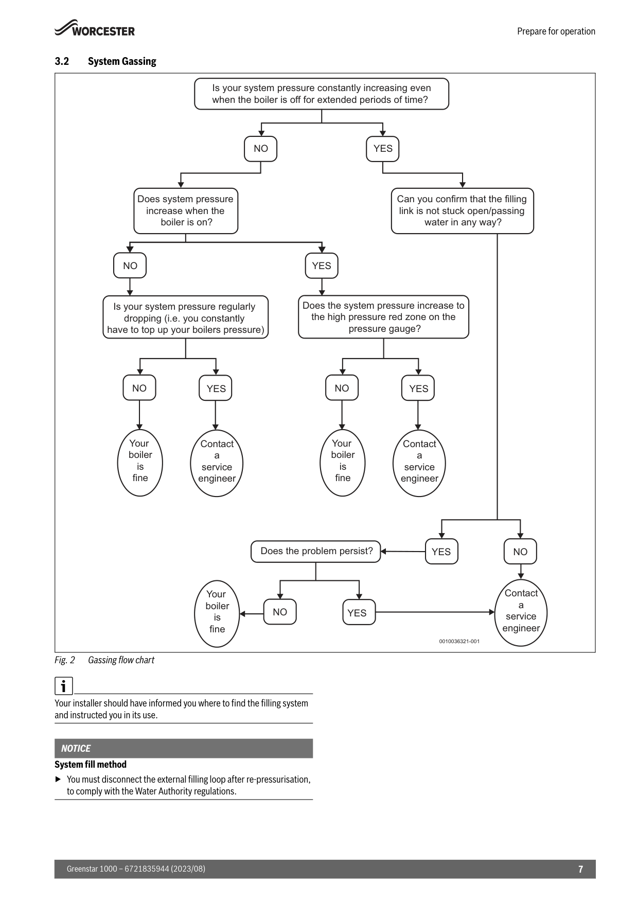
Prepare for operation 7 Greenstar 1000 – 6721835944 (2023/08) 3.2 System Gassing Fig. 2 Gassing flow chart Your installer should have informed you where to find the filling system and instructed you in its use.
Notice
System fill method ▶You must disconnect the external filling loop after re-pressurisation, to comply with the Water Authority regulations. Is your system pressure constantly increasing even when the boiler is off for extended periods of time?No
No
No
Yes
Yes
Yes
Is your system pressure regularly dropping (i.e. you constantly have to top up your boilers pressure) Can you confirm that the filling link is not stuck open/passing water in any way? Does system pressure increase when the boiler is on? Does the system pressure increase to the high pressure red zone on the pressure gauge? Does the problem persist? Contact a service engineerNo
Yes
Your boiler is fine 0010036321-001No
Your boiler is fineYes
Contact a service engineerNo
Your boiler is fineYes
Contact a service engineer
Prepare for operation Greenstar 1000 – 6721835944 (2023/08) 8 External filling loop Once the external filling loop and pressure gauge has been located, follow the instructions for re-pressurising the system. Refer to figure 3. ▶Unscrew the blanking cap [1]. ▶Attach the hose [2] to the valve. – Usually one end of the hose is already connected to one of the system fill isolation valves. ▶Ensure both ends [3] of the hose are screwed on hand tight. – The system fill isolation valves [4] are in a closed position (the handle/screwdriver slot is across the valve). ▶Turn the handle/screwdriver slot through 90° to open valves and slowly fill the system to between 1 and 1.5bar. – The system fill isolation valves [5] are opened (the handle/ screwdriver slot is in-line with the valve). – The needle on the pressure gauge will start to rise. ▶Turn the handles/screwdriver slots back, through 90°, to close the valves. – The system fill isolation valves [6] are in a closed position (the handle/screwdriver slot is across the valve). ▶Top up the system pressure, if as a result of the air bleeding the pressure drops off. ▶Remove the hose [2] and replace the blanking cap [1]. Fig. 3 External filling loop If the pressure gauge reads more than 1.5 bar as a result of over filling: ▶Bleed one radiator until the pressure gauge returns to between 1 and 1.5 bar. ▶It is good practice to bleed any excess air that has entered the heating system due to pressure loss. Locate and open the radiator's bleed/ vent point, closing the valve when water begins to flow. ▶If, through normal boiler operation, the PRV pipe starts to leak, it could be a sign of system pressure being too high. In this instance please bleed a radiator as described above.
Warning
Risk of damage to the system from corrosion! If the pressure in your heating system is repeatedly rising and you are repeatedly venting radiators, this can indicate that there is corrosion occurring within the heating system. To prevent serious damage to the entire system: ▶Contact a heating engineer. Failure to properly maintain the heating system may affect your warranty. System pressure can be checked via the boiler’s pressure gauge/reading when the system is cold, ensuring the reading is in the green zone at all times.Caution
Caution must be exercised when venting radiators or re-pressurising/ topping up the heating system: ▶Do not vent air from radiators whilst the central heating is switched on. ▶Allow 30 minutes after venting the radiators before using central heating or hot water. ▶Whilst venting radiators, do not allow the pressure to drop below the green zone on the boiler’s pressure gauge/reading. If symptoms persist: ▶Do not repeatedly vent your radiators. ▶Contact a heating engineer. 0010015034-001 1 2 3 4 5 6 Min 1 bar 1.5 bar Max
Operation 9 Greenstar 1000 – 6721835944 (2023/08) 4 Operation These operating instructions describe the operation of the gas-fired condensing boiler. Therefore please also observe the operating instructions for the user interface. 4.1 Switching on/off the appliance Switching on After initial power-up of the appliance, the appliance will initiate siphon fill mode. When and the flow temperature appear alternately on the display, the appliance remains at minimum heat output for 15 minutes to fill the condensate trap. Switching off
Notice
Risk of damage to the system from frost! The heating system can freeze after a prolonged period (e.g. during a power failure, switching off the power supply, faulty fuel supply, appliance fault etc.). ▶Ensure that the heating system is in constant use (particularly when there is a risk of frost). Frost protection for the heating system is only ensured if the heating pump is operational and is pumping heating water through the entire system. ▶Leave the heating switched on. ▶Set the time control to constant ON and set the room thermostat to12 °C.
The anti-seizing function is not active when the appliance is switched off. The anti-seizing function prevents the heating pump and the diverter valve from seizing up following long periods of inactivity. 4.2 Control panel overview Fig. 4 [1] Display [2] ( Heating mode on/off, set the maximum flow temperature [3]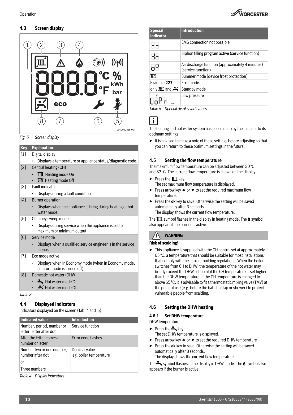
Operation Greenstar 1000 – 6721835944 (2023/08) 10 4.3 Screen display Fig. 5 Screen display Table 3 4.4 Displayed Indicators Indicators displayed on the screen (Tab. 4 and 5): Table 4 Display indicators Table 5 Special display indicators The heating and hot water system has been set up by the installer to its optimum settings. ▶It is advised to make a note of these settings before adjusting so that you can return to these optimum settings in the future. 4.5 Setting the flow temperature The maximum flow temperature can be adjusted between 30 °C and 82 °C. The current flow temperature is shown on the display. ▶Press the ( key. The set maximum flow temperature is displayed. ▶Press arrow key or to set the required maximum flow temperature. ▶Press the ok key to save. Otherwise the setting will be saved automatically after 3 seconds. The display shows the current flow temperature. The ( symbol flashes in the display in heating mode. The B symbol also appears if the burner is active.
Warning
Risk of scalding! ▶This appliance is supplied with the CH control set at approximately 65 °C, a temperature that should be suitable for most installations that comply with the current building regulations. When the boiler switches from CH to DHW, the temperature of the hot water may briefly exceed the DHW set point if the CH temperature is set higher than the DHW temperature. If the CH temperature is changed to above 65 °C, it is advisable to fit a thermostatic mixing valve (TMV) at the point of use (e.g. before the bath hot tap or shower) to protect vulnerable people from scalding. 4.6 Setting the DHW heating 4.6.1 Set DHW temperature DHW temperature: ▶Press the * key. The set DHW temperature is displayed. ▶Press arrow key or to set the required DHW temperature ▶Press the ok key to save. Otherwise the setting will be saved automatically after 3 seconds. The display shows the current flow temperature. The * symbol flashes in the display in DHW mode. The B symbol also appears if the burner is active. Key Explanation [1] Digital display • Displays a temperature or appliance status/diagnostic code. [2] Central heating (CH) • ( Heating mode On • ] Heating mode Off [3] Fault indicator • Displays during a fault condition. [4] Burner operation • Displays when the appliance is firing during heating or hot water mode. [5] Chimney sweep mode • Displays during service when the appliance is set to maximum or minimum output. [6] Service mode • Displays when a qualified service engineer is in the service menus. [7] Eco mode active • Displays when in Economy mode (when in Economy mode, comfort mode is turned off) [8] Domestic hot water (DHW) •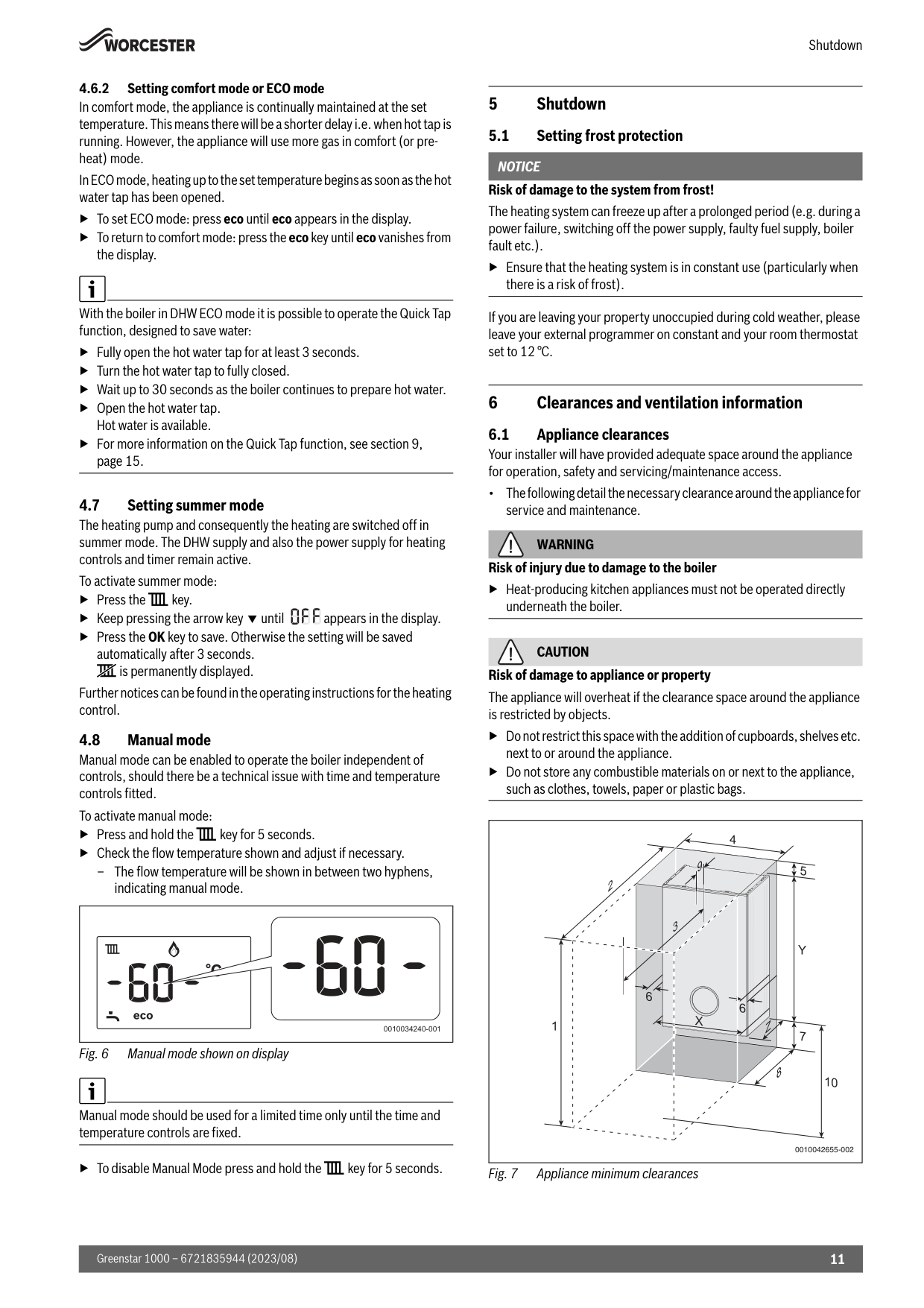
Shutdown 11 Greenstar 1000 – 6721835944 (2023/08) 4.6.2 Setting comfort mode or ECO mode In comfort mode, the appliance is continually maintained at the set temperature. This means there will be a shorter delay i.e. when hot tap is running. However, the appliance will use more gas in comfort (or pre- heat) mode. In ECO mode, heating up to the set temperature begins as soon as the hot water tap has been opened. ▶To set ECO mode: press eco until eco appears in the display. ▶To return to comfort mode: press the eco key until eco vanishes from the display. With the boiler in DHW ECO mode it is possible to operate the Quick Tap function, designed to save water: ▶Fully open the hot water tap for at least 3 seconds. ▶Turn the hot water tap to fully closed. ▶Wait up to 30 seconds as the boiler continues to prepare hot water. ▶Open the hot water tap. Hot water is available. ▶For more information on the Quick Tap function, see section 9, page 15. 4.7 Setting summer mode The heating pump and consequently the heating are switched off in summer mode. The DHW supply and also the power supply for heating controls and timer remain active. To activate summer mode: ▶Press the ( key. ▶Keep pressing the arrow key until appears in the display. ▶Press the OK key to save. Otherwise the setting will be saved automatically after 3 seconds. ] is permanently displayed. Further notices can be found in the operating instructions for the heating control. 4.8 Manual mode Manual mode can be enabled to operate the boiler independent of controls, should there be a technical issue with time and temperature controls fitted. To activate manual mode: ▶Press and hold the ( key for 5 seconds. ▶Check the flow temperature shown and adjust if necessary. – The flow temperature will be shown in between two hyphens, indicating manual mode. Fig. 6 Manual mode shown on display Manual mode should be used for a limited time only until the time and temperature controls are fixed. ▶To disable Manual Mode press and hold the ( key for 5 seconds. 5 Shutdown 5.1 Setting frost protection
Notice
Risk of damage to the system from frost! The heating system can freeze up after a prolonged period (e.g. during a power failure, switching off the power supply, faulty fuel supply, boiler fault etc.). ▶Ensure that the heating system is in constant use (particularly when there is a risk of frost). If you are leaving your property unoccupied during cold weather, please leave your external programmer on constant and your room thermostat set to 12 °C. 6 Clearances and ventilation information 6.1 Appliance clearances Your installer will have provided adequate space around the appliance for operation, safety and servicing/maintenance access. • The following detail the necessary clearance around the appliance for service and maintenance.Warning
Risk of injury due to damage to the boiler ▶Heat-producing kitchen appliances must not be operated directly underneath the boiler.Caution
Risk of damage to appliance or property The appliance will overheat if the clearance space around the appliance is restricted by objects. ▶Do not restrict this space with the addition of cupboards, shelves etc. next to or around the appliance. ▶Do not store any combustible materials on or next to the appliance, such as clothes, towels, paper or plastic bags. Fig. 7 Appliance minimum clearances 0010034240-001 0010042655-002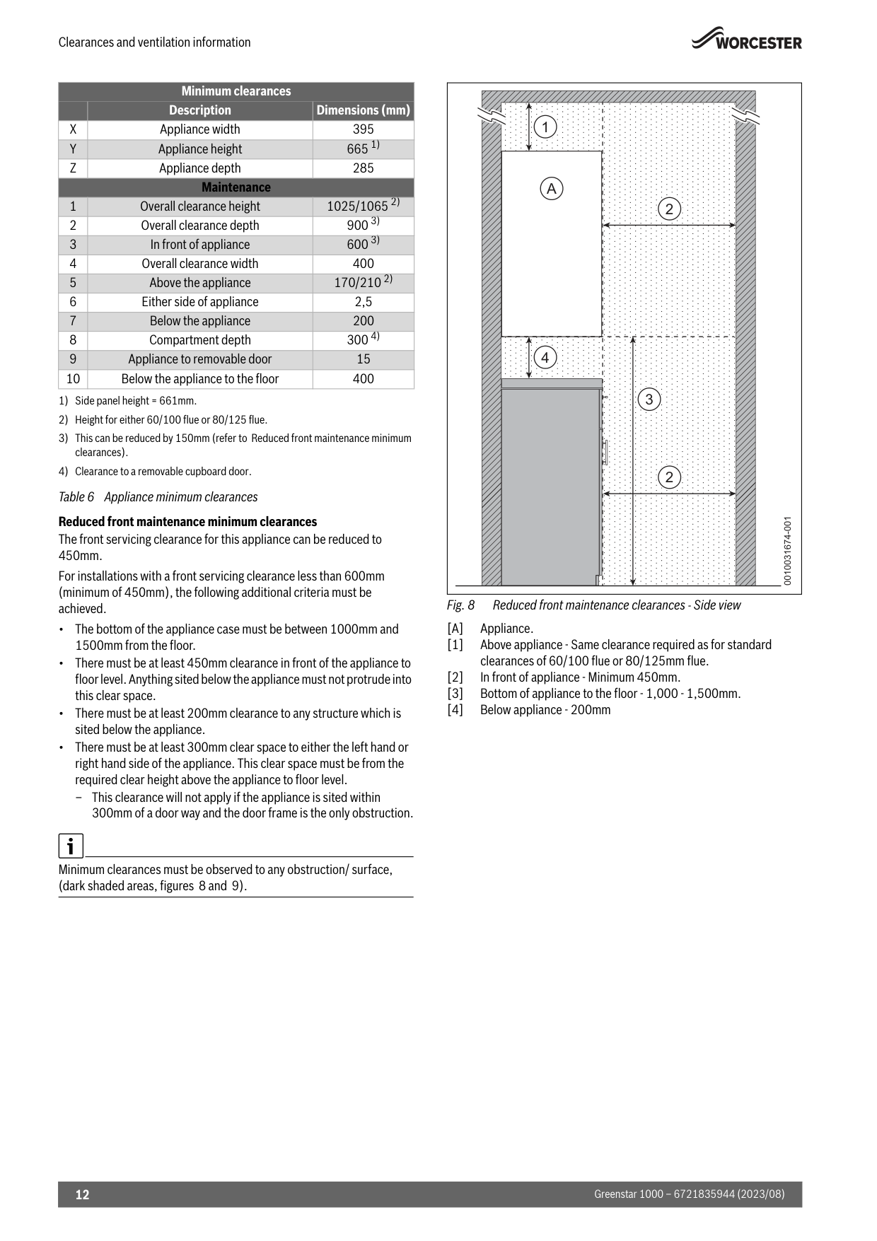
Clearances and ventilation information Greenstar 1000 – 6721835944 (2023/08) 12 Table 6 Appliance minimum clearances Reduced front maintenance minimum clearances The front servicing clearance for this appliance can be reduced to 450mm. For installations with a front servicing clearance less than 600mm (minimum of 450mm), the following additional criteria must be achieved. • The bottom of the appliance case must be between 1000mm and 1500mm from the floor. • There must be at least 450mm clearance in front of the appliance to floor level. Anything sited below the appliance must not protrude into this clear space. • There must be at least 200mm clearance to any structure which is sited below the appliance. • There must be at least 300mm clear space to either the left hand or right hand side of the appliance. This clear space must be from the required clear height above the appliance to floor level. – This clearance will not apply if the appliance is sited within 300mm of a door way and the door frame is the only obstruction. Minimum clearances must be observed to any obstruction/ surface, (dark shaded areas, figures 8 and 9). Fig. 8 Reduced front maintenance clearances - Side view
[A]
Appliance. [1] Above appliance - Same clearance required as for standard clearances of 60/100 flue or 80/125mm flue. [2] In front of appliance - Minimum 450mm. [3] Bottom of appliance to the floor - 1,000 - 1,500mm. [4] Below appliance - 200mm Minimum clearances Description Dimensions (mm)X
Appliance width 395Y
Appliance height 665 1) 1) Side panel height = 661mm.Z
Appliance depth 285 Maintenance 1 Overall clearance height 1025/1065 2) 2) Height for either 60/100 flue or 80/125 flue. 2 Overall clearance depth 900 3) 3) This can be reduced by 150mm (refer to Reduced front maintenance minimum clearances). 3 In front of appliance 600 3) 4 Overall clearance width 400 5 Above the appliance 170/210 2) 6 Either side of appliance 2,5 7 Below the appliance 200 8 Compartment depth 300 4) 4) Clearance to a removable cupboard door. 9 Appliance to removable door 15 10 Below the appliance to the floor 400 0010031674-001 1 2 2 4 3A
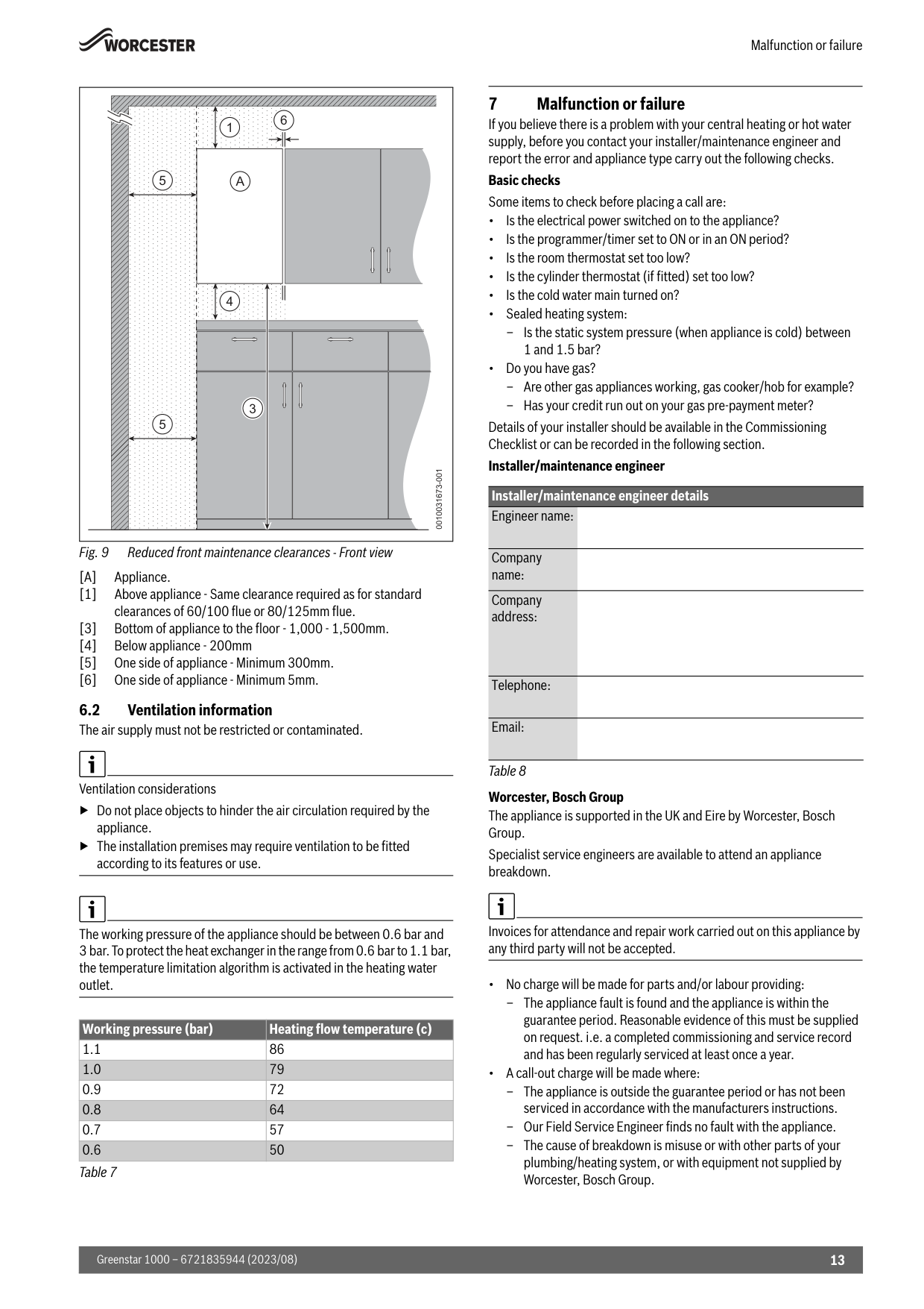
Malfunction or failure 13 Greenstar 1000 – 6721835944 (2023/08) Fig. 9 Reduced front maintenance clearances - Front view
[A]
Appliance. [1] Above appliance - Same clearance required as for standard clearances of 60/100 flue or 80/125mm flue. [3] Bottom of appliance to the floor - 1,000 - 1,500mm. [4] Below appliance - 200mm [5] One side of appliance - Minimum 300mm. [6] One side of appliance - Minimum 5mm. 6.2 Ventilation information The air supply must not be restricted or contaminated. Ventilation considerations ▶Do not place objects to hinder the air circulation required by the appliance. ▶The installation premises may require ventilation to be fitted according to its features or use. The working pressure of the appliance should be between 0.6 bar and 3 bar. To protect the heat exchanger in the range from 0.6 bar to 1.1 bar, the temperature limitation algorithm is activated in the heating water outlet. Table 7 7 Malfunction or failure If you believe there is a problem with your central heating or hot water supply, before you contact your installer/maintenance engineer and report the error and appliance type carry out the following checks. Basic checks Some items to check before placing a call are: • Is the electrical power switched on to the appliance? • Is the programmer/timer set to ON or in an ON period? • Is the room thermostat set too low? • Is the cylinder thermostat (if fitted) set too low? • Is the cold water main turned on? • Sealed heating system: – Is the static system pressure (when appliance is cold) between 1 and 1.5 bar? • Do you have gas? – Are other gas appliances working, gas cooker/hob for example? – Has your credit run out on your gas pre-payment meter? Details of your installer should be available in the Commissioning Checklist or can be recorded in the following section. Installer/maintenance engineer Table 8 Worcester, Bosch Group The appliance is supported in the UK and Eire by Worcester, Bosch Group. Specialist service engineers are available to attend an appliance breakdown. Invoices for attendance and repair work carried out on this appliance by any third party will not be accepted. • No charge will be made for parts and/or labour providing: – The appliance fault is found and the appliance is within the guarantee period. Reasonable evidence of this must be supplied on request. i.e. a completed commissioning and service record and has been regularly serviced at least once a year. • A call-out charge will be made where: – The appliance is outside the guarantee period or has not been serviced in accordance with the manufacturers instructions. – Our Field Service Engineer finds no fault with the appliance. – The cause of breakdown is misuse or with other parts of your plumbing/heating system, or with equipment not supplied by Worcester, Bosch Group. Working pressure (bar) Heating flow temperature (c) 1.1 86 1.0 79 0.9 72 0.8 64 0.7 57 0.6 50 0010031673-001 1 6 5 5 4 3A
Installer/maintenance engineer details Engineer name: Company name: Company address: Telephone: Email: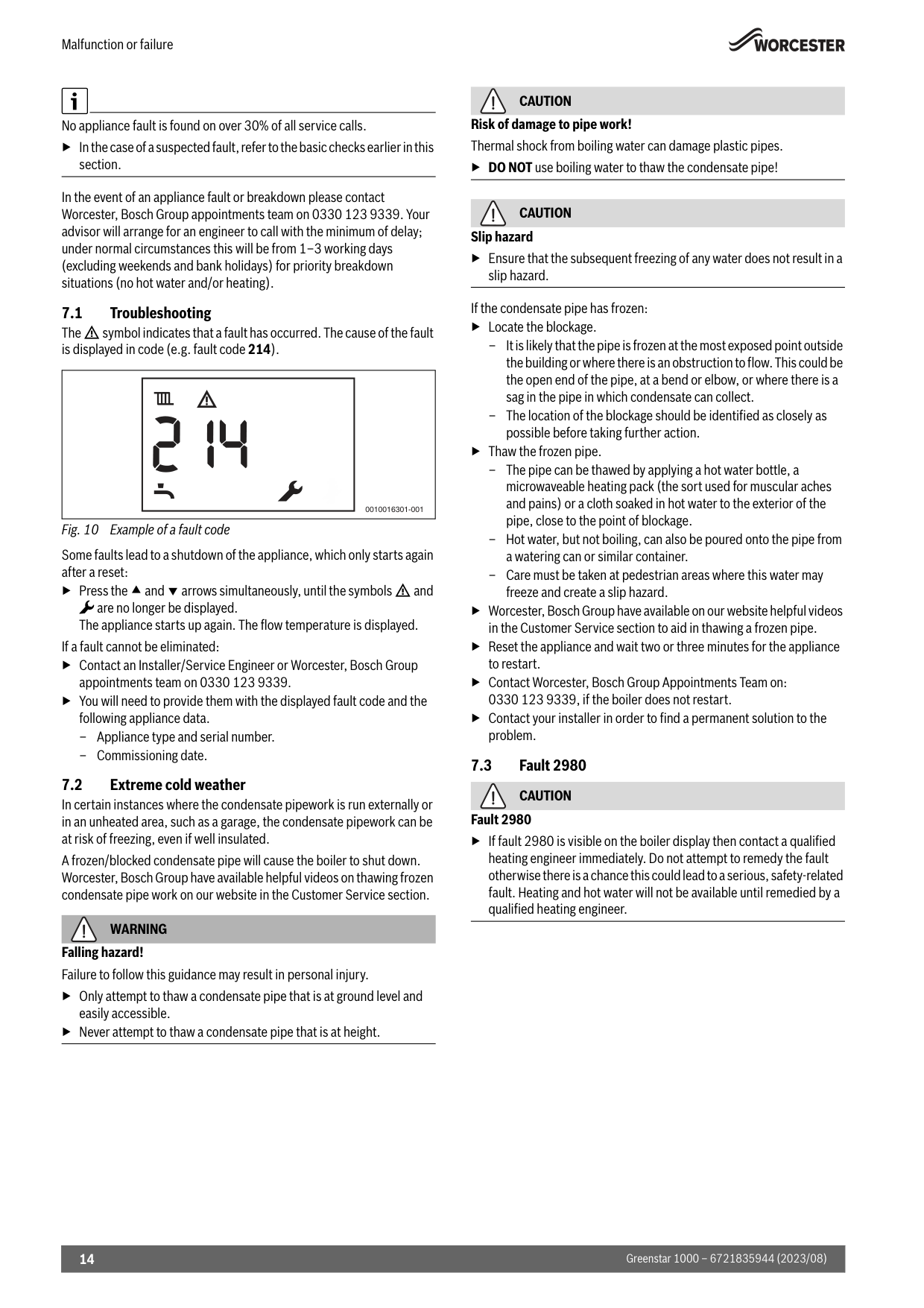
Malfunction or failure Greenstar 1000 – 6721835944 (2023/08) 14 No appliance fault is found on over 30% of all service calls. ▶In the case of a suspected fault, refer to the basic checks earlier in this section. In the event of an appliance fault or breakdown please contact Worcester, Bosch Group appointments team on 0330 123 9339. Your advisor will arrange for an engineer to call with the minimum of delay; under normal circumstances this will be from 1‒3 working days (excluding weekends and bank holidays) for priority breakdown situations (no hot water and/or heating). 7.1 Troubleshooting The H symbol indicates that a fault has occurred. The cause of the fault is displayed in code (e.g. fault code 214). Fig. 10 Example of a fault code Some faults lead to a shutdown of the appliance, which only starts again after a reset: ▶Press the and arrows simultaneously, until the symbols H and ! are no longer be displayed. The appliance starts up again. The flow temperature is displayed. If a fault cannot be eliminated: ▶Contact an Installer/Service Engineer or Worcester, Bosch Group appointments team on 0330 123 9339. ▶You will need to provide them with the displayed fault code and the following appliance data. – Appliance type and serial number. – Commissioning date. 7.2 Extreme cold weather In certain instances where the condensate pipework is run externally or in an unheated area, such as a garage, the condensate pipework can be at risk of freezing, even if well insulated. A frozen/blocked condensate pipe will cause the boiler to shut down. Worcester, Bosch Group have available helpful videos on thawing frozen condensate pipe work on our website in the Customer Service section.
Warning
Falling hazard! Failure to follow this guidance may result in personal injury. ▶Only attempt to thaw a condensate pipe that is at ground level and easily accessible. ▶Never attempt to thaw a condensate pipe that is at height.Caution
Risk of damage to pipe work! Thermal shock from boiling water can damage plastic pipes. ▶DO NOT use boiling water to thaw the condensate pipe!Caution
Slip hazard ▶Ensure that the subsequent freezing of any water does not result in a slip hazard. If the condensate pipe has frozen: ▶Locate the blockage. – It is likely that the pipe is frozen at the most exposed point outside the building or where there is an obstruction to flow. This could be the open end of the pipe, at a bend or elbow, or where there is a sag in the pipe in which condensate can collect. – The location of the blockage should be identified as closely as possible before taking further action. ▶Thaw the frozen pipe. – The pipe can be thawed by applying a hot water bottle, a microwaveable heating pack (the sort used for muscular aches and pains) or a cloth soaked in hot water to the exterior of the pipe, close to the point of blockage. – Hot water, but not boiling, can also be poured onto the pipe from a watering can or similar container. – Care must be taken at pedestrian areas where this water may freeze and create a slip hazard. ▶Worcester, Bosch Group have available on our website helpful videos in the Customer Service section to aid in thawing a frozen pipe. ▶Reset the appliance and wait two or three minutes for the appliance to restart. ▶Contact Worcester, Bosch Group Appointments Team on: 0330 123 9339, if the boiler does not restart. ▶Contact your installer in order to find a permanent solution to the problem. 7.3 Fault 2980Caution
Fault 2980 ▶If fault 2980 is visible on the boiler display then contact a qualified heating engineer immediately. Do not attempt to remedy the fault otherwise there is a chance this could lead to a serious, safety-related fault. Heating and hot water will not be available until remedied by a qualified heating engineer. 0010016301-001
Environmental protection and disposal 15 Greenstar 1000 – 6721835944 (2023/08) 8 Environmental protection and disposal Environmental protection is a fundamental corporate strategy of the Bosch Group. The quality of our products, their economy and environmental safety are all of equal importance to us and all environmental protection legislation and regulations are strictly observed. We use the best possible technology and materials for protecting the environment taking account of economic considerations. Packaging Where packaging is concerned, we participate in country-specific recycling processes that ensure optimum recycling. All of our packaging materials are environmentally compatible and can be recycled. Compostable packaging Compostable packaging is used wherever possible in an effort to reduce the product’s impact on the environment and the overall demand for plastic packaging. Where the following symbol is shown the material is compostable: Compostable packaging can be disposed of in a number of ways: • Home compost heap • Local Authority garden waste collection • Local Authority food waste collection, ideally as a food waste bin bag • Local Authority household waste Please note that compostable materials cannot be recycled. Used appliances Used appliances contain valuable materials that can be recycled. The various assemblies can be easily dismantled. Synthetic materials are marked accordingly. Assemblies can therefore be sorted by composition and passed on for recycling or disposal. Old electrical and electronic appliances This symbol means that the product must not be disposed of with other waste, and instead must be taken to the waste collection points for treatment, collection, recycling and disposal. The symbol is valid in countries where waste electrical and electronic equipment regulations apply, e.g. "(UK) Waste Electrical and Electronic Equipment Regulations 2013 (as amended)". These regulations define the framework for the return and recycling of old electronic appliances that apply in each country. As electronic devices may contain hazardous substances, it needs to be recycled responsibly in order to minimize any potential harm to the environment and human health. Furthermore, recycling of electronic scrap helps preserve natural resources. For additional information on the environmentally compatible disposal of old electrical and electronic appliances, please contact the relevant local authorities, your household waste disposal service or the retailer where you purchased the product. You can find more information here: www.bosch-homecomfortgroup.com/en/company/legal-topics/weee/ Batteries Batteries must not be disposed together with your household waste. Used batteries must be disposed of in local collection systems. 9 Tips on energy saving Quick Tap function ▶Fully open your hot water tap for at least 3 seconds. This ignites the boiler. ▶Turn hot water tap to fully closed. ▶Wait up to 30 seconds1) as the boiler continues to prepare hot water. ▶Open your hot water tap; hot water is available2) On average, 3.5 litres of water can be saved when using the Quick Tap function. Water saving varies depending on user behaviour, pipework design and the time of year, for example, if Central Heating is on during the winter, DHW will heat up quicker than in the summer, reducing the potential for water saving. Savings are calculated based on average mains water pressure, a heat-up time of 30 seconds and close proximity of the tap to the boiler. Heating economically The appliance provides a high level of comfort whilst keeping fuel consumption and the environment effects as low as possible. The appliance is controlled in such a way that it delivers heat at the correct rate and only if there is a clear demand from the system. Central heating systems with thermostatic radiator valves With modern heating systems set around a 20 °C heat loss, the optimum setting for a condensing boiler will be approximately 65 °C for the central heating temperature. This is to ensure a return temperature of less than
52 °C.
The system must be balanced correctly and the radiators may need upgrading. This allows the boiler to condense as much as possible for the central heating system. The temperature of each room can be set individually (except primary room with the room thermostat) using the thermostatic radiator valves. Room thermostats Reducing the setting of the room thermostat by 1 °C can reduce fuel consumption by up to 10%. New control systems Upgrade your heating control system if necessary with the latest equipment available. Roof insulation Around 30% of the heat loss from a property is through the roof. Replace any old insulation with new insulation, preferably of around 200mm thickness or more. Window frames Single glazed windows, particularly those with steel frames, can lose a great deal of heat. Consideration should be given to replacement with PVCu or wooden framed double glazed units. 1) If the hot water reaches the set temperature before 30 seconds has elapsed, the boiler will stop firing 2) Hot water is available at the boiler. Delivery time to the tap will vary on the pipework design and tap distance from the boiler
Your guarantee Greenstar 1000 – 6721835944 (2023/08) 16 Radiators If a radiator is sited underneath a window, its performance will be affected if the curtains are allowed to drape over the radiator. Shelves fitted above or in front of the radiator should also be avoided. It is advisable to manually adjust all thermostatic radiator valves every 2‒3 months to prevent them sticking. Ensure radiator valves are correctly set and not damaged. Draughts Try to ensure that draughts around doors, windows, letter boxes and keyholes etc. are reduced by using a suitable draught excluder.
Warning
Air vents! ▶Do not block or seal any air vents that are installed to ensure that the appliance operates safely. Curtains Lined curtains, or heavier full length curtains can provide excellent insulation. However, always ensure that the curtains do not drape over radiators. 10 Your guarantee This appliance has a guarantee against faulty materials or workmanship from the date of installation subject to the following terms and conditions: • During the period of this guarantee any components of the appliance that are proven to be faulty or defective in manufacture will be exchanged or repaired free of charge by Bosch Thermotechnology Ltd. • The householder may be asked to prove the date of installation, that the appliance was correctly commissioned and, where appropriate, serviced to the satisfaction of Bosch Thermotechnology Ltd. These should be documented in the commissioning and service records in the Installation and Maintenance Instructions. • The appliance has been used only for the normal domestic purposes for which it was designed. This guarantee does not affect your statutory rights. Guarantee registration Your appliance/product carries a guarantee against faulty material or manufacture subject to Terms and Conditions. To read the full Terms & Conditions please visit us on-line at www.worcester-bosch.co.uk/guarantee. Your statutory rights are not affected by the manufacturer’s guarantee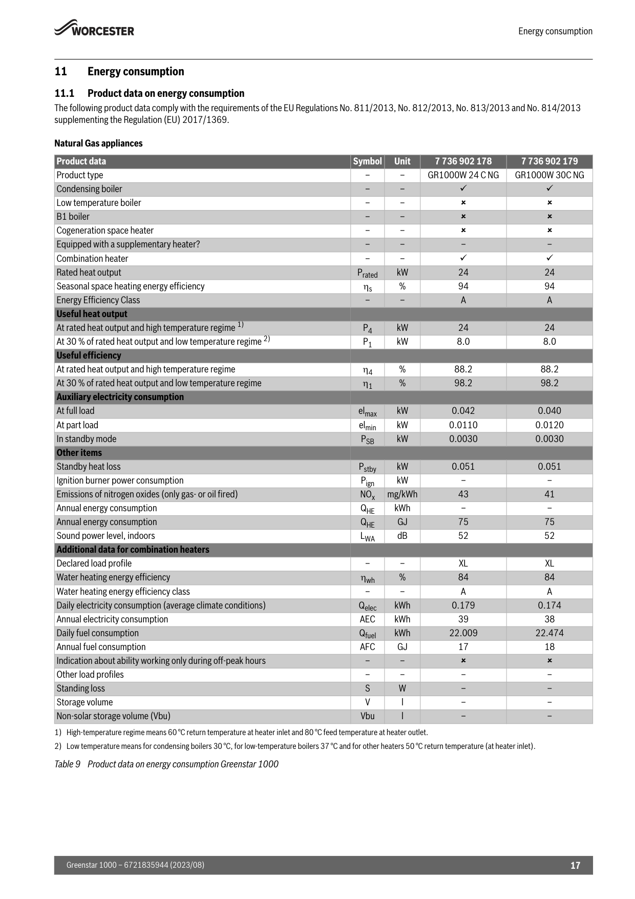
Energy consumption 17 Greenstar 1000 – 6721835944 (2023/08) 11 Energy consumption 11.1 Product data on energy consumption The following product data comply with the requirements of the EU Regulations No. 811/2013, No. 812/2013, No. 813/2013 and No. 814/2013 supplementing the Regulation (EU) 2017/1369. Natural Gas appliances Table 9 Product data on energy consumption Greenstar 1000 Product data Symbol Unit 7 736 902 178 7 736 902 179 Product type – –
Gr1000W 24 C Ng
Gr1000W 30C Ng
Condensing boiler – – Low temperature boiler – – B1 boiler – – Cogeneration space heater – – Equipped with a supplementary heater? – – – – Combination heater – – Rated heat output Prated kW 24 24 Seasonal space heating energy efficiency s % 94 94 Energy Efficiency Class – –A
A
Useful heat output At rated heat output and high temperature regime 1) 1) High-temperature regime means 60 °C return temperature at heater inlet and 80 °C feed temperature at heater outlet.P4
kW 24 24 At 30 % of rated heat output and low temperature regime 2) 2) Low temperature means for condensing boilers 30 °C, for low-temperature boilers 37 °C and for other heaters 50 °C return temperature (at heater inlet).P1
kW 8.0 8.0 Useful efficiency At rated heat output and high temperature regime 4 % 88.2 88.2 At 30 % of rated heat output and low temperature regime 1 % 98.2 98.2 Auxiliary electricity consumption At full load elmax kW 0.042 0.040 At part load elmin kW 0.0110 0.0120 In standby modePsb
kW 0.0030 0.0030 Other items Standby heat loss Pstby kW 0.051 0.051 Ignition burner power consumption Pign kW – – Emissions of nitrogen oxides (only gas- or oil fired) NOx mg/kWh 43 41 Annual energy consumptionQhe
kWh – – Annual energy consumptionQhe
Gj
75 75 Sound power level, indoorsLwa
dB 52 52 Additional data for combination heaters Declared load profile – –Xl
Xl
Water heating energy efficiency wh % 84 84 Water heating energy efficiency class – –A
A
Daily electricity consumption (average climate conditions) Qelec kWh 0.179 0.174 Annual electricity consumptionAec
kWh 39 38 Daily fuel consumption Qfuel kWh 22.009 22.474 Annual fuel consumptionAfc
Gj
17 18 Indication about ability working only during off-peak hours – – Other load profiles – – – – Standing lossS
W
– – Storage volumeV
l – – Non-solar storage volume (Vbu) Vbu l – –
Data Protection Notice Greenstar 1000 – 6721835944 (2023/08) 18 12 Data Protection Notice We, Bosch Thermotechnology Ltd., Cotswold Way, Warndon, Worcester WR4 9SW, United Kingdom process product and installation information, technical and connection data, communication data, product registration and client history data to provide product functionality (art. 6 (1) sentence 1 (b) GDPR / UK GDPR), to fulfil our duty of product surveillance and for product safety and security reasons (art. 6 (1) sentence 1 (f) GDPR / UK GDPR), to safeguard our rights in connection with warranty and product registration questions (art. 6 (1) sentence 1 (f) GDPR / UK GDPR) and to analyze the distribution of our products and to provide individualized information and offers related to the product (art. 6 (1) sentence 1 (f) GDPR / UK GDPR). To provide services such as sales and marketing services, contract management, payment handling, programming, data hosting and hotline services we can commission and transfer data to external service providers and/or Bosch affiliated enterprises. In some cases, but only if appropriate data protection is ensured, personal data might be transferred to recipients located outside of the European Economic Area and the United Kingdom. Further information are provided on request. You can contact our Data Protection Officer under: Data Protection Officer, Information Security and Privacy (C/ISP), Robert Bosch GmbH, Postfach 30 02 20, 70442 Stuttgart, GERMANY. You have the right to object, on grounds relating to your particular situation or where personal data are processed for direct marketing purposes, at any time to processing of your personal data which is based on art. 6 (1) sentence 1 (f) GDPR / UK GDPR. To exercise your rights, please contact us via [email protected] To find further information, please follow the QR-Code.

Bosch Thermotechnology Ltd. Cotswold Way, Warndon Worcester WR4 9SW United Kingdom Tel. 0330 123 9559 worcester-bosch.co.uk