Honeywell Set Temp RTH5160 Thermostat
Ask AI
— answers from the official manualAnswers from the official manual.
Common questions
Common Questions
114 totalHow do I install the Honeywell RTH5160 thermostat?
Start by turning off power at the breaker box and documenting your old thermostat's wiring with photos and labels. Remove the old thermostat's faceplate, then disconnect the wires using a screwdriver. Insert the wires through the UWP mounting system, set the R-switch position based on your wiring (up for 1 R-wire, down for 2 R-wires), and connect all wires to their matching terminals. Install two AA alkaline batteries, attach the thermostat to the UWP, and turn power back on.
What are the system setup options for the Honeywell thermostat?
The thermostat has several key setup numbers including temperature scale (125), heating system type (200), heating equipment type (205), reversing valve setting (218), cooling stages (220), heat stages (221), and system changeover mode (300). Each setup number has multiple configuration options to match your specific HVAC equipment. Access system setup by pressing and holding the Menu button for approximately 5 seconds from the home screen.
What battery type does the RTH5160 thermostat require?
The thermostat requires two AA alkaline batteries for power. The low battery icon will appear approximately two months before batteries are depleted. You should replace batteries once a year or before leaving home for more than a month, even if the low battery icon hasn't appeared. If batteries are replaced within two minutes, the time and day settings will be preserved.
What system modes are available on the Honeywell thermostat?
Available system modes include Auto (thermostat automatically selects heating or cooling as needed), Heat (heating system only), Cool (cooling system only), Em Heat (auxiliary heat only, available only on heat pumps), and Off (both systems off, though fan may still run if set to On). To change modes, press Menu and then Mode, cycle through options until you see the desired mode, and press Done.
Why isn't my heating or cooling system responding?
Several steps can resolve this issue: first, press Menu and Mode to set the system to Heat (ensure temperature is higher than inside temperature) or Cool (ensure temperature is lower than inside temperature). Check the circuit breaker and reset if necessary, verify the power switch at the heating/cooling system is on, ensure the furnace door is closed securely, and wait 5 minutes for the system to respond. If the system still doesn't work, check your System Setup Options 200 or 218 to ensure they match your equipment.
What wiring does the RTH5160 thermostat support?
The RTH5160 supports R, Rh, Rc, Y, G, C, O/B, W, W2, E, A, K, and Aux terminals. It does NOT support L/A, S, or U terminals. For conventional systems, the thermostat accommodates either 1 R-wire or 2 R-wires (R/Rh and Rc) with the R-switch set accordingly. The C terminal does not power the display or operations—batteries are always required. If you have wires in unsupported terminals, contact Honeywell support at yourhome.honeywell.com/support.
Show 108 more questions
What do the alert codes mean on my Honeywell thermostat?
How do I troubleshoot a blank display on the RTH5160?
Why are 'Heat On' or 'Cool On' flashing on my thermostat screen?
How do I set the fan mode on the RTH5160 thermostat?
Why is it important to take a picture of my old thermostat wiring?
How much wire should be exposed when inserting wires through the UWP?
What battery type and quantity does the RTH5160 require?
How do I know if my current system is compatible with the RTH5160?
What should I do if my thermostat wires have faded colors?
How much of each wire should be exposed when inserting it through the UWP?
What is the R-switch and how do I set it?
How many screws should I use to mount the UWP to the wall?
How do I access System Setup after initial installation?
What should I do if my old thermostat has a K-wire terminal?
Why should I take a picture of my old thermostat's wiring before removal?
How do I safely turn off power before removing my old thermostat?
What should I do before disconnecting wires from my old thermostat?
Can the RTH5160 work with a 120V or line voltage system?
How do I know whether to set the R-switch up or down?
How do I secure the thermostat to the wall after wiring?
What should I do if my old thermostat used a K terminal wire?
How do I re-enter System Setup after the initial installation?
What should I do before removing my old thermostat?
What is the correct way to set the R-switch on the RTH5160?
How do I secure the thermostat to the wall?
What should I do if my old thermostat has a K wire?
How do I take a picture of my old thermostat wiring for reference?
What should I do if wire colors have faded or if two terminals have the same wire color?
What tools do I need to install the RTH5160 thermostat?
What should I do if my system has 120V or higher line voltage wires?
What is the difference between setting the R-switch up versus down?
How many batteries does the RTH5160 require and what type?
Why should I take a picture of my old thermostat wiring before disconnecting?
What should I do if the color of wires has faded or multiple terminals have the same wire color?
How many screws are needed to securely mount the UWP to the wall?
How do I re-enter System Setup after initial installation?
How do I safely remove my old thermostat before installing the RTH5160?
What should I do if I have two R-wires (both R and Rc)?
Do I need a C (Common) wire to power the RTH5160 display?
How do I secure the UWP mounting system to the wall?
What batteries does the RTH5160 require, and how do I install them?
What should I do if the wire colors have faded or if two terminals have the same wire color?
How do I verify that my wiring is correct after installation?
Can the RTH5160 be installed on a 120V or higher line voltage system?
What should I do if my wire colors have faded or two terminals have the same wire color?
How do I set the R-switch on the RTH5160?
What type of batteries does the RTH5160 require and how many?
What should I do if wires are not securely inserted into the UWP terminals?
What tools are required to install the Honeywell RTH5160 thermostat?
What should I do if my thermostat has 120/240V wires or thick black wires with wire nuts?
How do I set the R-switch position on the RTH5160?
What type and how many batteries does the RTH5160 require?
How do I verify that wires are securely connected to the terminals?
What should I do if the color of my wires has faded or if two terminals have the same wire color?
Does the RTH5160 support all terminal types from my old thermostat?
How do I know if my current thermostat system is compatible with the RTH5160?
What is the recommended drill bit size for installing wall anchors with the RTH5160?
What is the correct way to expose wires before inserting them into the RTH5160 terminals?
How should I position the R-switch on the RTH5160?
What should I do before removing the old thermostat?
How many screws are needed to mount the RTH5160 on the wall?
What should I do if I need to disconnect a wire after inserting it into a terminal?
What should I do if the wire color has faded on my old thermostat?
How many screws are required to securely mount the UWP to the wall?
What should I do if I need to release a wire from a terminal after installation?
How do I verify that the power is off before removing my old thermostat?
What should I do if my thermostat has 120V or higher line voltage wires?
When should I set the R-switch to the down position?
What batteries are required to power the RTH5160 thermostat?
What should I do if wire colors have faded or multiple terminals have the same wire color?
Does the RTH5160 support L/A, S, or U terminal wiring?
What type and quantity of batteries does the RTH5160 require?
Does the C terminal provide power to the RTH5160 thermostat display?
What tools are required to install the RTH5160 thermostat?
How do I know if my old thermostat has power before removing it?
How do I set the R-switch on the UWP?
How many screws are needed to mount the UWP to the wall?
Which terminal wires does the RTH5160 not support?
How do I re-enter System Setup after leaving the home screen?
How much of each wire should be exposed when installing the RTH5160?
What types of HVAC systems are NOT compatible with the RTH5160?
How should I prepare the wires before inserting them into the UWP mounting system?
What is the proper way to set the R-switch position on the UWP?
How many screws should be used to mount the UWP to the wall?
What should I do if the wire colors on my old thermostat have faded?
What is the proper wire exposure length needed when installing the RTH5160?
How many screws are needed to mount the RTH5160 UWP to the wall?
What should I do if my thermostat wires have faded colors or duplicate colors?
How do I verify that my wires are securely connected to the RTH5160 terminals?
Does the RTH5160 support L/A, S, or U terminal wires?
How can I tell if my heating system is incompatible with the RTH5160?
Why is taking a picture of the old thermostat wiring important?
What is the correct way to prepare wires for insertion into the UWP terminals?
What should I do if my thermostat has thick black wires with wire nuts?
How do I know if my system has enough power to turn off before installation?
Can the RTH5160 work with a line voltage system?
What is the minimum wire exposure needed when inserting wires through the UWP?
How should I position the R-switch based on my wiring configuration?
What size drill bit should I use when installing wall anchors for the RTH5160?
How much of each wire should be exposed when inserting them through the UWP?
What is the correct R-switch position if I have only one R-wire?
What is the correct R-switch position if I have two R-wires?
What type of batteries does the RTH5160 require?
How do I re-enter the System Setup menu after initial installation?
Can I use the RTH5160 with a system that has a K-wire terminal?
What should I do if my existing wires have faded colors or duplicate colors?
How do I know if my system has power before removing the old thermostat?
What should I do if my thermostat has 120V or higher wires?
Full Manual
32 pages
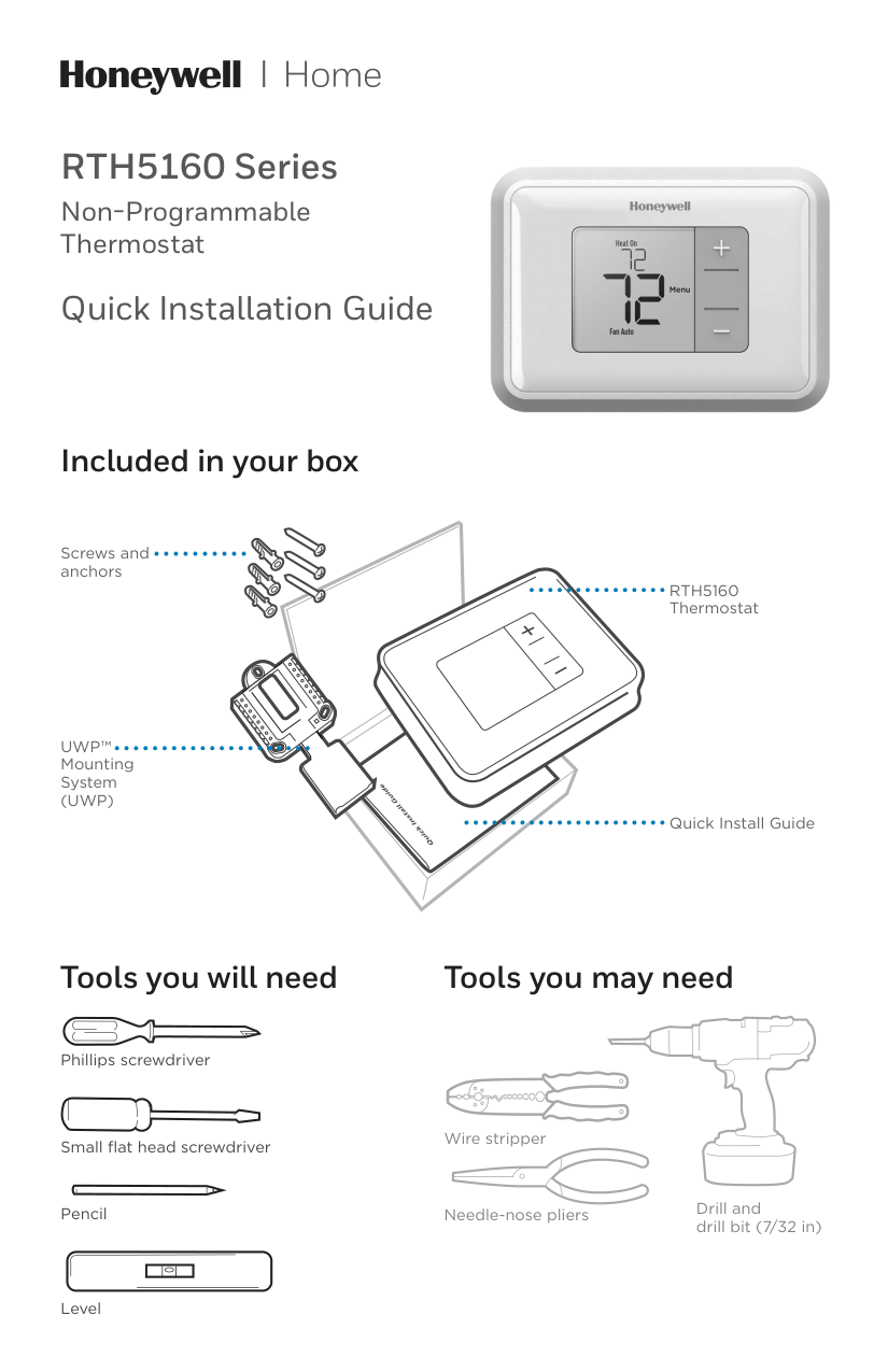
RTH5160 Series Non-Programmable Thermostat Quick Installation Guide Tools you will need Tools you may need Wire stripper Needle-nose pliers Drill and drill bit (7/32 in) Included in your box Screws and anchors
Uwp™
Mounting System(Uwp)
Rth5160
Thermostat Quick Install Guide Small flat head screwdriver Phillips screwdriver Pencil Level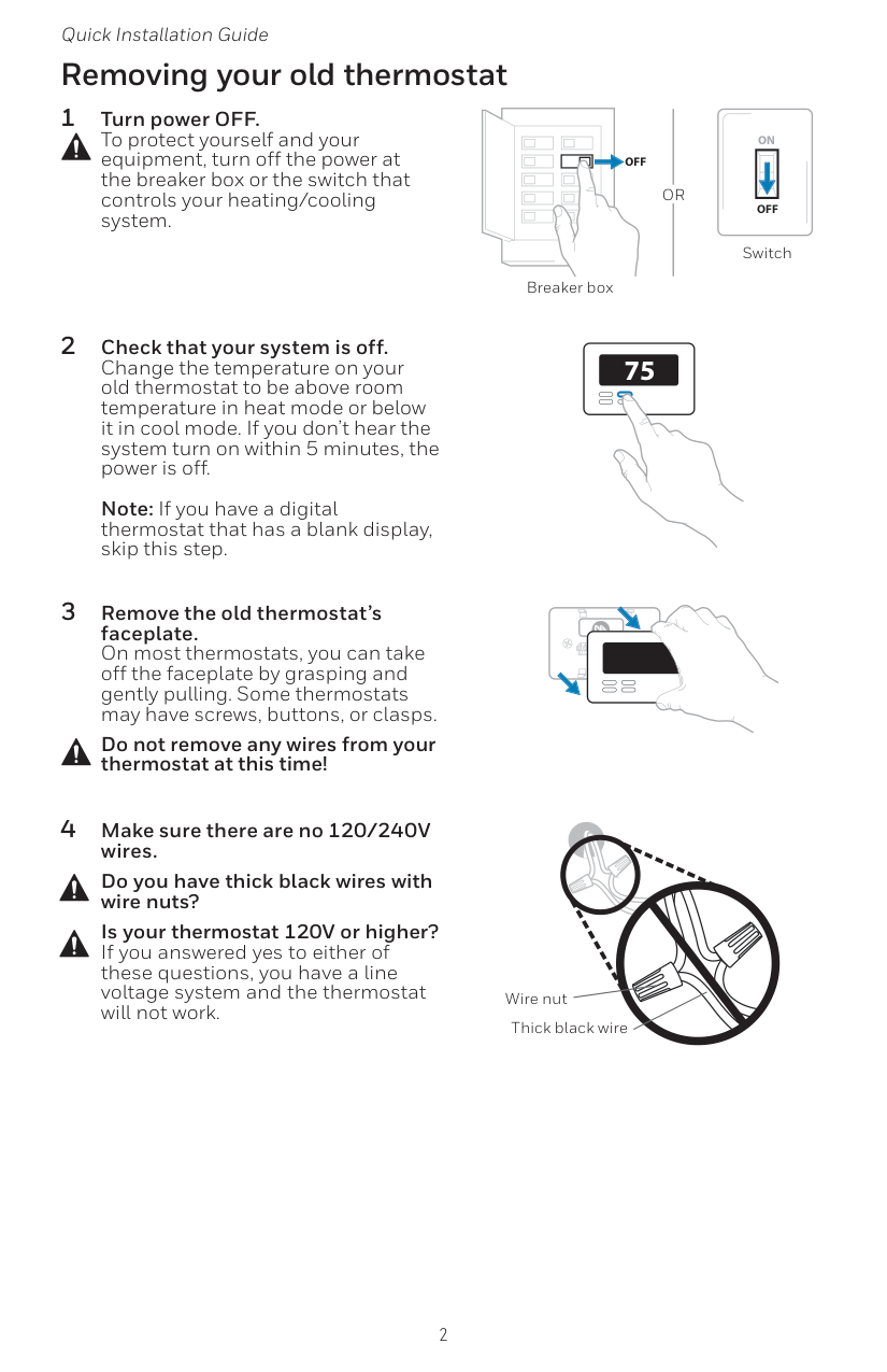
2 Quick Installation Guide Removing your old thermostat 2 Check that your system is off. Change the temperature on your old thermostat to be above room temperature in heat mode or below it in cool mode. If you don’t hear the system turn on within 5 minutes, the power is off.
Note: If you have a digital thermostat that has a blank display, skip this step. 1 Turn power OFF. To protect yourself and your equipment, turn off the power at the breaker box or the switch that controls your heating/cooling system. 3 Remove the old thermostat’s faceplate. On most thermostats, you can take off the faceplate by grasping and gently pulling. Some thermostats may have screws, buttons, or clasps. Do not remove any wires from your thermostat at this time! 75
Off
Off
On
Breaker box Switch 4 Make sure there are no 120/240V wires. Do you have thick black wires with wire nuts? Is your thermostat 120V or higher? If you answered yes to either of these questions, you have a line voltage system and the thermostat will not work. Wire nut Thick black wireOr
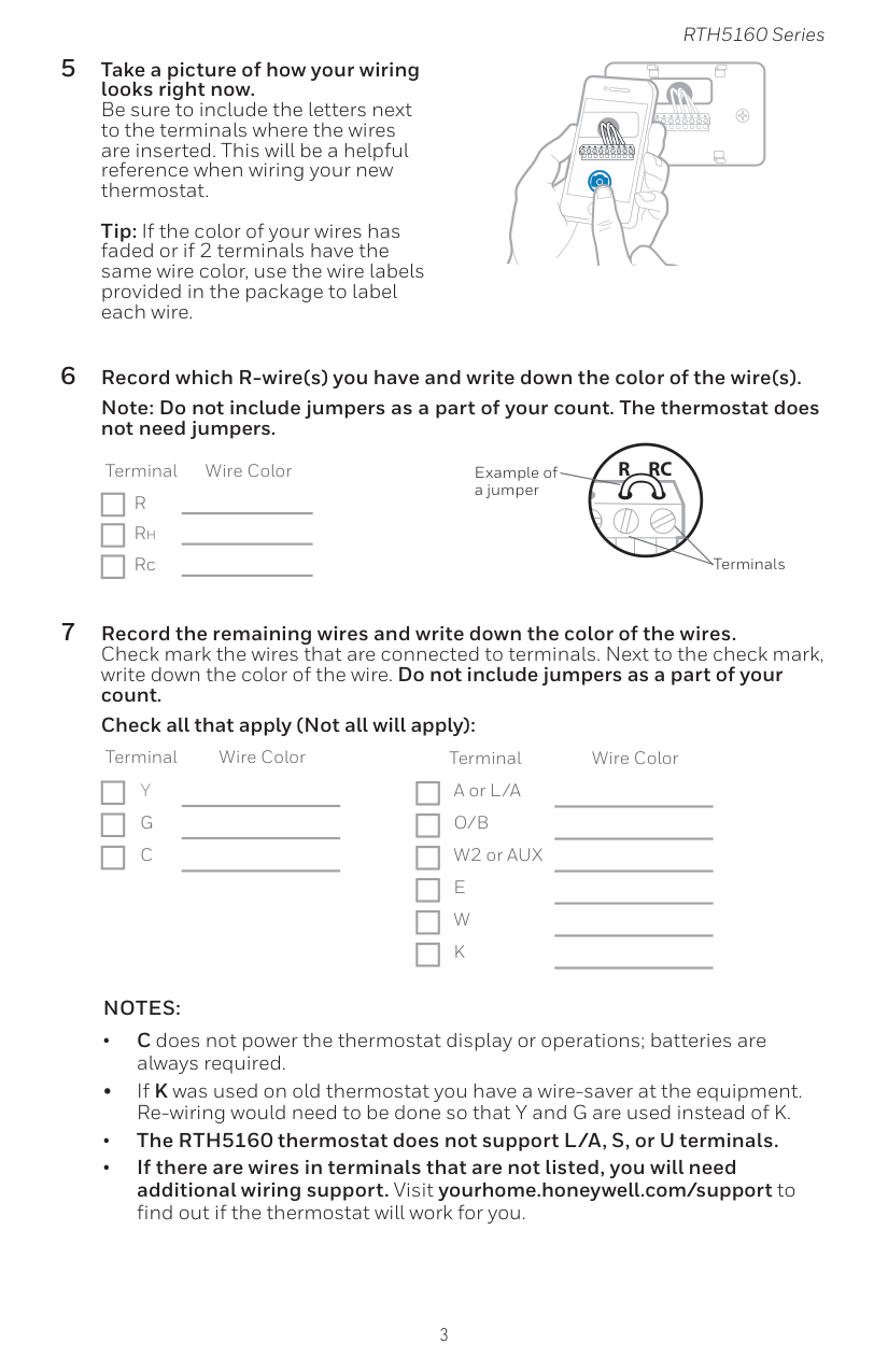
3 RTH5160 Series 5 Take a picture of how your wiring looks right now. Be sure to include the letters next to the terminals where the wires are inserted. This will be a helpful reference when wiring your new thermostat.
Tip: If the color of your wires has faded or if 2 terminals have the same wire color, use the wire labels provided in the package to label each wire.
Y
R
Rc
Example of a jumper Terminals 6 Record which R-wire(s) you have and write down the color of the wire(s). Note: Do not include jumpers as a part of your count. The thermostat does not need jumpers. Terminal Wire ColorR
Rh Rc 7 Record the remaining wires and write down the color of the wires. Check mark the wires that are connected to terminals. Next to the check mark, write down the color of the wire. Do not include jumpers as a part of your count. Check all that apply (Not all will apply): Terminal Wire ColorY
G
C
Terminal Wire Color A or L/AO/B
W2 or AUXE
W
K
Notes:
• C does not power the thermostat display or operations; batteries are always required. • If K was used on old thermostat you have a wire-saver at the equipment. Re-wiring would need to be done so that Y and G are used instead of K. • The RTH5160 thermostat does not support L/A, S, or U terminals. • If there are wires in terminals that are not listed, you will need additional wiring support. Visit yourhome.honeywell.com/support to find out if the thermostat will work for you.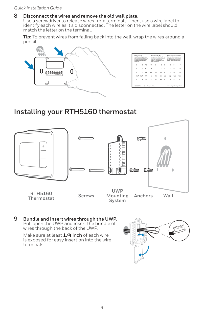
4 Quick Installation Guide 8 Disconnect the wires and remove the old wall plate. Use a screwdriver to release wires from terminals. Then, use a wire label to identify each wire as it’s disconnected. The letter on the wire label should match the letter on the terminal. Tip: To prevent wires from falling back into the wall, wrap the wires around a pencil. Installing your RTH5160 thermostat 9 Bundle and insert wires through the UWP. Pull open the UWP and insert the bundle of wires through the back of the UWP. Make sure at least 1/4 inch of each wire is exposed for easy insertion into the wire terminals.
Rth5160
Thermostat ScrewsUwp
Mounting System Anchors Wall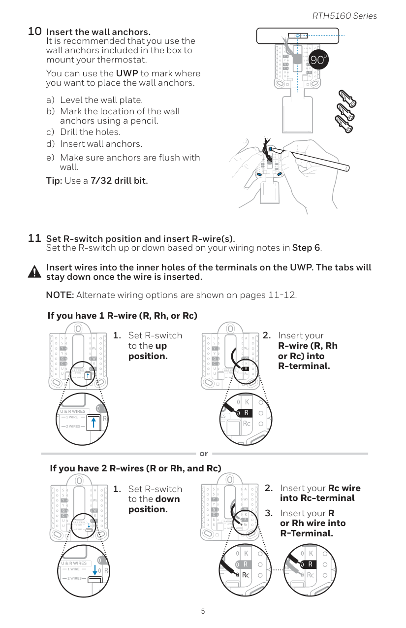
5 RTH5160 Series 10 Insert the wall anchors. It is recommended that you use the wall anchors included in the box to mount your thermostat. You can use the UWP to mark where you want to place the wall anchors. a) Level the wall plate. b) Mark the location of the wall anchors using a pencil. c) Drill the holes. d) Insert wall anchors. e) Make sure anchors are flush with wall. Tip: Use a 7/32 drill bit. Insert wires into the inner holes of the terminals on the UWP. The tabs will stay down once the wire is inserted. If you have 1 R-wire (R, Rh, or Rc) If you have 2 R-wires (R or Rh, and Rc) or

6 Quick Installation Guide 13 Confirm wiring matches snapshot. Please confirm wiring matches terminals from the photo you took in Step 5. 14 Mount the UWP and close the door. Mount the UWP using the provided screws. Install all three screws for a secure fit on your wall. Close the door after you’re finished. Use 3x supplied screws #8 1-1/2” 12 Connect remaining wires. Depress the tabs to put the wires into the inner holes of the corresponding terminals on the UWP (one wire per terminal) until it is firmly in place. Gently tug on the wires to verify they are secure. Tip: If you need to release a wire again, push down the corresponding terminal tab on the side of the UWP. NOTE: Alternate wiring options are shown on pages 11-12. This wiring is just an example, yours may vary.
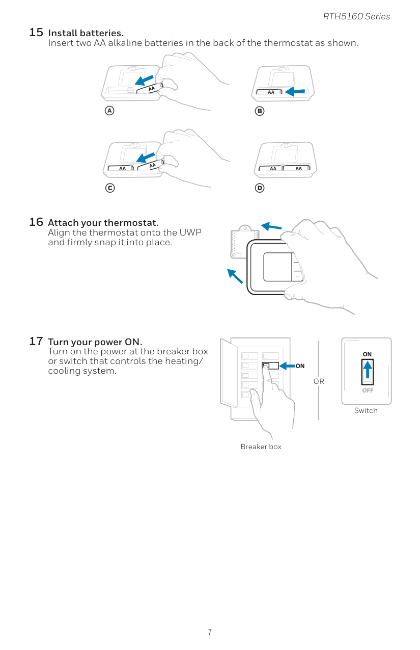
7 RTH5160 Series 15 Install batteries. Insert two AA alkaline batteries in the back of the thermostat as shown. 16 Attach your thermostat. Align the thermostat onto the UWP and firmly snap it into place. 17 Turn your power ON. Turn on the power at the breaker box or switch that controls the heating/ cooling system.
On
Off
On
Breaker box SwitchOr

8 Quick Installation Guide Now that you have installed your thermostat, please follow the steps below to setup your system and personalize your thermostat. 18 Select System Setup options. Press Edit (-) to change values or select from available options. Then press Next (+) to save changes and advance to the next System Setup number. See “System Setup options” on the next page for a full list of System Setup numbers and options. Repeat until all of the System Setup options have been set, and then press Done. The thermostat will save and exit to the home screen. 19 Continue to “System operation settings” on page 10. System Setup Setup number Option number NOTE: To re-enter the System Setup from the Home Screen, press and hold the Menu button for approximately 5 seconds.

9 RTH5160 Series System Setup Number and Description Options (factory default in bold) 125 = Temperature Indication Scale 0 = Fahrenheit 1 = Celsius 200 = Heating System Type 1 = Conventional Forced Air Heat 2 = Heat Pump 3 = Radiant Heat (Boiler) 5 = None (Cool Only) Note: This option selects the basic system type your thermostat will control. 205 = Heating Equipment Type Conventional Forced Air Heat: 1 = Standard Efficiency Gas Forced Air 2 = High Efficiency Gas Forced Air 3 = Oil Forced Air 4 = Electric Forced Air 5 = Hot Water Fan Coil Heat Pump: 7 = Air to Air Heat Pump Radiant Heat: 9 = Hot Water Radiant Heat 12 = Steam Note: This option selects the equipment type your thermostat will control. This feature is NOT displayed if feature 200 is set to Cool Only. 218 = Reversing Valve O/B 0 = O (O/B in Cool) 1 = B (O/B in Heat) Note: This option is only displayed if the Heat Pump configured. Select whether reversing valve O/B should energize in cool or in heat. 220 = Cool Stages / Compressor Stages (200=Conv / 200=HP) 0, 1, 2 Note: Select how many Cool or Compressor stages of your equipment the thermostat will control. Maximum of 2 Cool stages or 1 Compressor stage. Set value to 0 if you do not have Cool Stage/Compressor Stage. 221 = Heat Stages / Backup Heat Stages Heat Stages: 1, 2 Backup Heat Stages: 0, 1 Note: Select how many Heat or Aux/E stages of your equipment the thermostat will control. Maximum of 2 Heat Stages for conventional systems. Maximum of 1 Aux/E stage for systems with more than 1 heating equipment type. Set value to 0 if you do not have Heat Stage/ Backup Heat Stage. 300 = System Changeover 0 = Manual 1 = Automatic Note: Thermostat can automatically control both heating and cooling to maintain the desired indoor temperature. To be able to select “automatic” system mode on thermostat home screen, turn this feature ON. Turn OFF if you want to control heating or cooling manually. NOTE: Once you have cycled through all of the System Setup numbers, press Done to save and exit to the home screen. System Setup options Setup Complete You have now finished installing and setting up your thermostat.

10 Quick Installation Guide Fan operation settings 1 Press Menu, and then press the Fan (-) button to cycle to the next available Fan mode. 2 Cycle through the modes until the required Fan mode is displayed, then press Done. NOTE: Available Fan modes vary with system settings. Fan modes: ‒‒ Auto: Fan runs only when the heating or cooling system is on. ‒‒ On: Fan is always on. System operation settings 1 Press Menu, and then press the Mode (+) button to cycle to the next available System mode. 2 Cycle through the modes until the required System mode is displayed, and then press Done. NOTE: Available System modes vary by model and system settings. System modes: ‒‒ Auto: Thermostat selects heating or cooling as needed. ‒‒ Heat: Thermostat controls only the heating system. ‒‒ Cool: Thermostat controls only the cooling system. ‒‒ Em Heat (only for heat pumps with auxiliary heat): Thermostat controls Auxiliary Heat. Compressor is not used. ‒‒ Off: Heating and cooling system is off. Fan will still operate if fan is set to On. NOTE: Heat On/Cool On may flash for 5 minutes due to compressor protection.
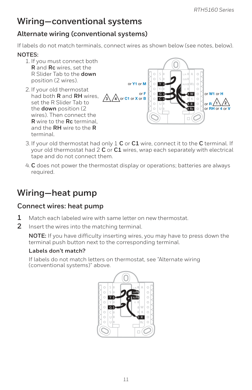
11 RTH5160 Series Wiring—conventional systems Alternate wiring (conventional systems) If labels do not match terminals, connect wires as shown below (see notes, below).
Notes:
Aux
S
S
Y
U
U
G
C
Y
A
RcW
K
W2
R
L/A
O/B
E
Aux
S
S
U
U
G
C
Y
A
RcW
K
W2
R
L/A
O/B
E
Y
4 2 2 3 or Y1 or M or F or C1 or X or B or W1 or H or R or RH or 4 or V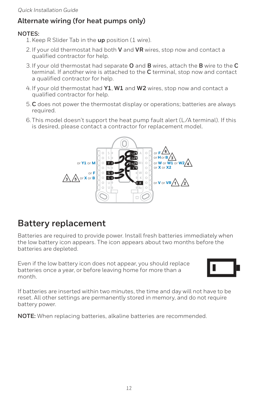
12 Quick Installation Guide Alternate wiring (for heat pumps only)
Notes:
Aux
S
S
Y
U
U
G
C
Y
A
RcW
K
W2
R
L/A
O/B
E
3 5 3 4 or X or B or F or Y1 or M 2 or H or B or V or VR or W or W1 or W2 or X or X2 or F 2 1 6
13 RTH5160 Series Alerts screen 1 You will see the alert icon and the alert number on the screen. 2 Press Next (+) to see additional alerts, if any. Then press Done to go back to the home screen. NOTE: If the alert is a critical alert, you may not be able to access the home screen and should call a HVAC professional. Number Alert/Reminder Definition 170 Internal Memory Error The memory of the thermostat has encountered an error. Please replace the thermostat. 173 Thermostat Temperature Sensor Error The sensor of the thermostat has encountered an error. Please replace the thermostat. 405 Low Battery Alert The batteries are getting low. Replace them within two months. 407 Critical Low Battery The batteries are almost depleted and should be replaced as soon as possible. Alerts codes
14 Quick Installation Guide If you have difficulty with your thermostat, please try the following suggestions. Most problems can be corrected quickly and easily. Display is blank Make sure fresh AA alkaline batteries are properly installed (see page 7). Cannot change system setting to Cool Check System Setup Option 220 to make sure the options are set to either 1 or 2 (see page 9). Fan does not turn on when heat is required Check System Setup Option 205 to make sure it is set to match your heating equipment (see page 9). Heating system is running in cool mode Check System Setup Option 200 or 218 to make sure it is set to match your heating and cooling equipment (see see page 9). Heating or cooling system does not respond Press Menu and then Mode to set system to Heat. Make sure the temperature is set higher than the Inside temperature. Press Menu and then Mode to set system to Cool. Make sure the temperature is set lower than the Inside temperature. Check circuit breaker and reset if necessary. Make sure power switch at heating & cooling system is on. Make sure furnace door is closed securely. Wait 5 minutes for the system to respond. Heat On / Cool On flashing on the screen Compressor protection feature is engaged. Wait 5 minutes for the system to restart safely, without damage to the compressor. Heat pump issues cool air in heat mode, or warm air in cool mode Check System Setup Option 200 or 218 to make sure it is set to match your heating and cooling equipment (see page 9). Troubleshooting
15 RTH5160 Series Honeywell warrants this product, excluding battery, to be free from defects in the workmanship or materials, under normal use and service, for a period of one (1) year from the date of purchase by the consumer. If at any time during the warranty period the product is determined to be defective or malfunctions, Honeywell shall repair or replace it (at Honeywell’s option). If the product is defective, (i) return it, with a bill of sale or other dated proof of purchase, to the place from which you purchased it; or (ii) call Honeywell Customer Care at 1-800-468-1502. Customer Care will make the determination whether the product should be returned to the following address: Honeywell Return Goods, Dock 4 MN10-3860, 1985 Douglas Dr. N., Golden Valley, MN 55422, or whether a replacement product can be sent to you. This warranty does not cover removal or reinstallation costs. This warranty shall not apply if it is shown by Honeywell that the defect or malfunction was caused by damage which occurred while the product was in the possession of a consumer. Honeywell’s sole responsibility shall be to repair or replace the product within the terms stated above. HONEYWELL SHALL NOT BE LIABLE FOR ANY LOSS
Or Damage Of Any Kind, Including Any Incidental Or Consequential
Damages Resulting, Directly Or Indirectly, From Any Breach Of Any
Warranty, Express Or Implied, Or Any Other Failure Of This Product.
Some states do not allow the exclusion or limitation of incidental or consequential damages, so this limitation may not apply to you.This Warranty Is The Only Express Warranty Honeywell Makes On
This Product. The Duration Of Any Implied Warranties, Including
The Warranties Of Merchantability And Fitness For A Particular
Purpose, Is Hereby Limited To The One-Year Duration Of This
Warranty.
Some states do not allow limitations on how long an implied warranty lasts, so the above limitation may not apply to you. This warranty gives you specific legal rights, and you may have other rights which vary from state to state. If you have any questions concerning this warranty, please write Honeywell Customer Relations, 1985 Douglas Dr, Golden Valley, MN 55422 or call 1-800- 468-1502. In Canada, write Retail Products ON15-02H, Honeywell Limited/ Honeywell Limitée, 35 Dynamic Drive, Toronto, Ontario M1V4Z9. 1-year limited warranty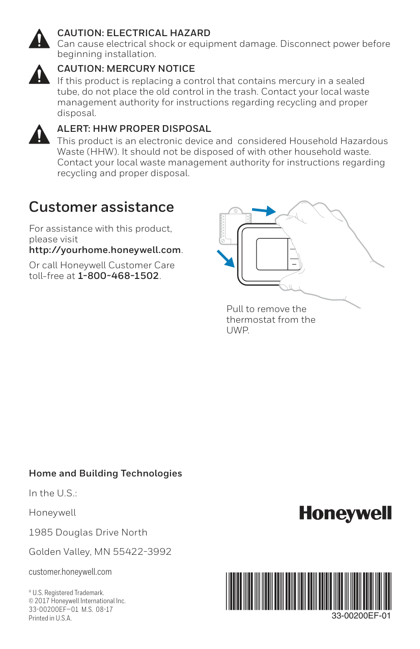
Home and Building Technologies In the U.S.: Honeywell 1985 Douglas Drive North Golden Valley, MN 55422-3992 customer.honeywell.com ® U.S. Registered Trademark. © 2017 Honeywell International Inc.
33-00200Ef—01 M.S. 08-17
Printed in U.S.A.33-00200Ef-01
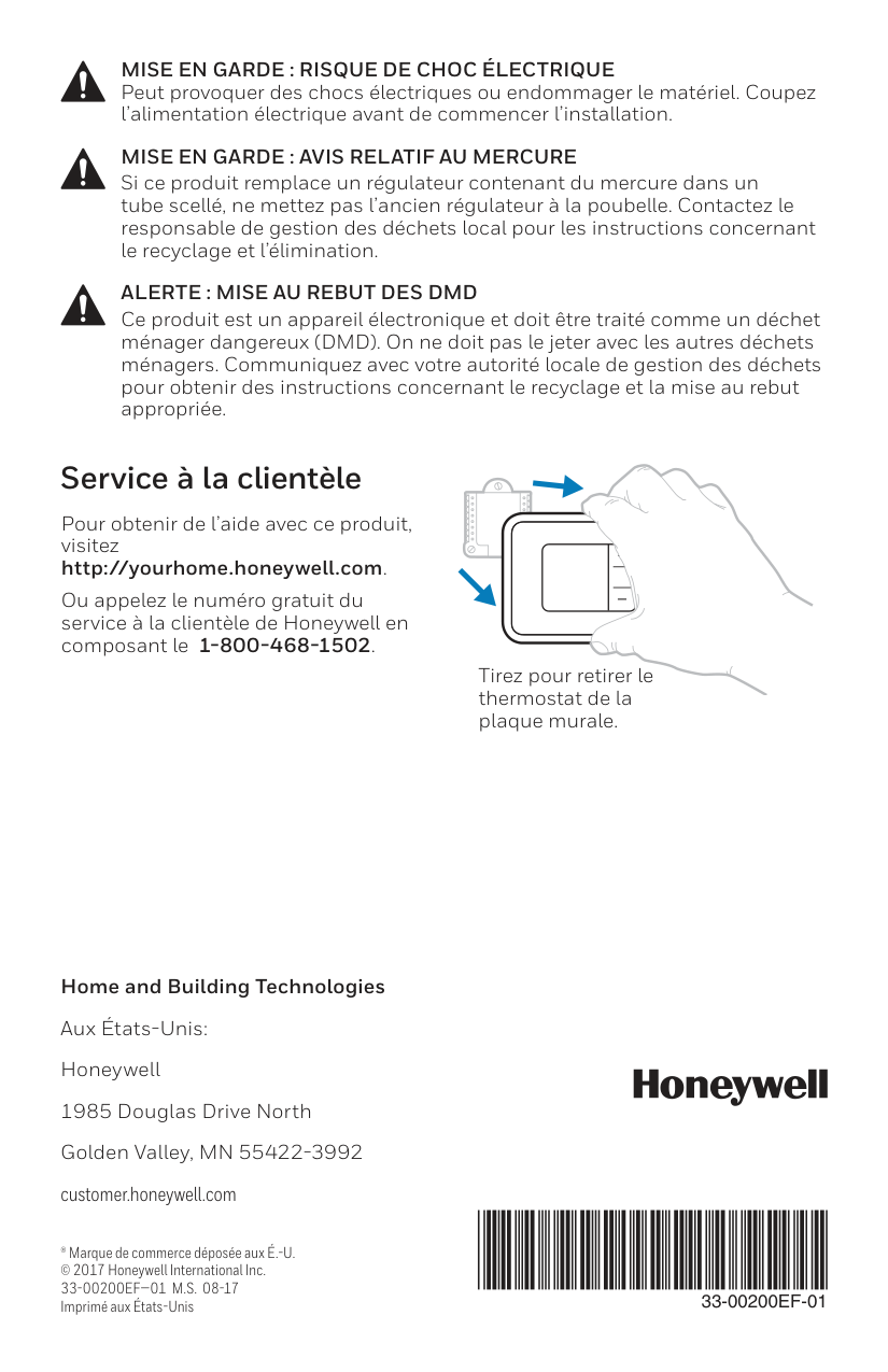
For assistance with this product, please visit http://yourhome.honeywell.com. Or call Honeywell Customer Care toll-free at 1-800-468-1502. Customer assistance Pull to remove the thermostat from theUwp.
Caution: Mercury Notice
If this product is replacing a control that contains mercury in a sealed tube, do not place the old control in the trash. Contact your local waste management authority for instructions regarding recycling and proper disposal.Caution: Electrical Hazard
Can cause electrical shock or equipment damage. Disconnect power before beginning installation.Alert: Hhw Proper Disposal
This product is an electronic device and considered Household Hazardous Waste (HHW). It should not be disposed of with other household waste. Contact your local waste management authority for instructions regarding recycling and proper disposal.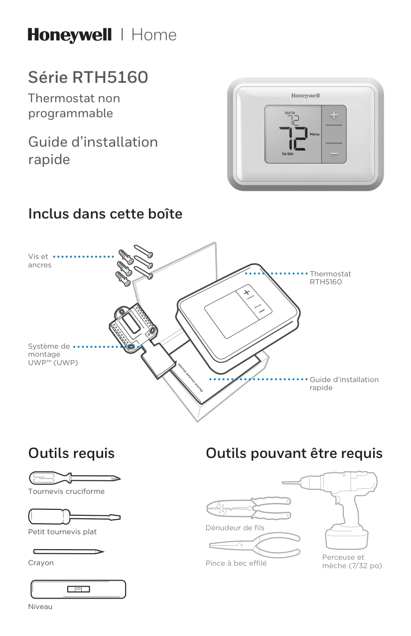
Série RTH5160 Thermostat non programmable Guide d’installation rapide Outils requis Outils pouvant être requis Dénudeur de fils Pince à bec effilé Perceuse et mèche (7/32 po) Inclus dans cette boîte Vis et ancres Système de montage
Uwp™ (Uwp)
ThermostatRth5160
Guide d’installation rapide Petit tournevis plat Tournevis cruciforme Crayon Niveau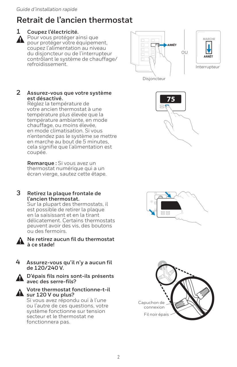
2 Guide d’installation rapide Retrait de l’ancien thermostat 2 Assurez-vous que votre système est désactivé. Réglez la température de votre ancien thermostat à une température plus élevée que la température ambiante, en mode chauffage, ou moins élevée, en mode climatisation. Si vous n’entendez pas le système se mettre en marche au bout de 5 minutes, cela signifie que l’alimentation est coupée.
Remarque : Si vous avez un thermostat numérique qui a un écran vierge, sautez cette étape. 1 Coupez l’électricité. Pour vous protéger ainsi que pour protéger votre équipement, coupez l’alimentation au niveau du disjoncteur ou de l’interrupteur contrôlant le système de chauffage/ refroidissement. 3 Retirez la plaque frontale de l’ancien thermostat. Sur la plupart des thermostats, il est possible de retirer la plaque en la saisissant et en la tirant délicatement. Certains thermostats peuvent avoir des vis, des boutons ou des fermoirs. Ne retirez aucun fil du thermostat à ce stade! 75 Disjoncteur Interrupteur 4 Assurez-vous qu’il n’y a aucun fil de 120/240 V. D’épais fils noirs sont-ils présents avec des serre-fils? Votre thermostat fonctionne-t-il sur 120 V ou plus? Si vous avez répondu oui à l’une ou l’autre de ces questions, votre système fonctionne sur tension secteur et le thermostat ne fonctionnera pas. Capuchon de connexion Fil noir épais
Ou
Arrêt
Arrêt
Marche
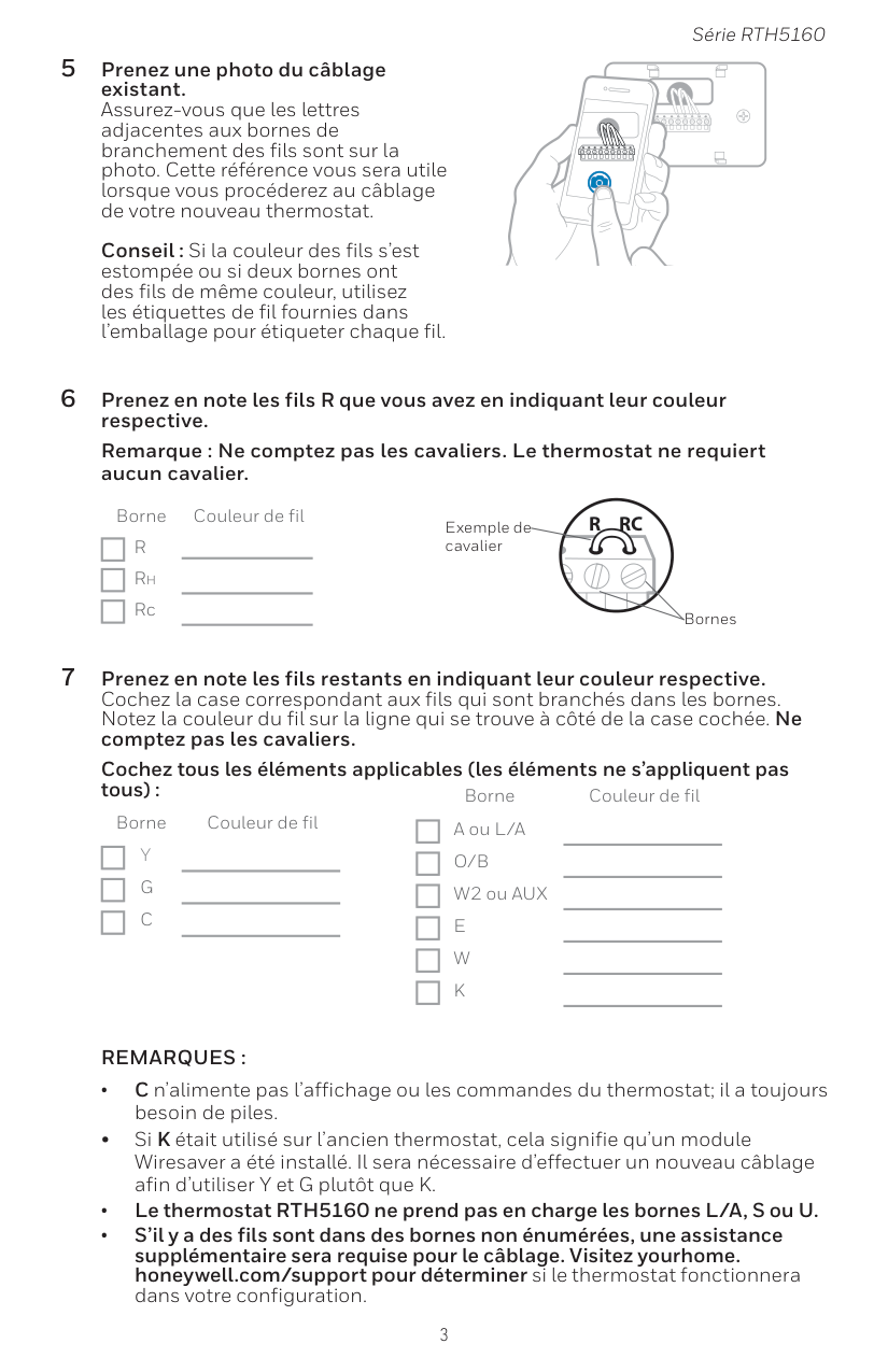
3 Série RTH5160 5 Prenez une photo du câblage existant. Assurez-vous que les lettres adjacentes aux bornes de branchement des fils sont sur la photo. Cette référence vous sera utile lorsque vous procéderez au câblage de votre nouveau thermostat.
Conseil : Si la couleur des fils s’est estompée ou si deux bornes ont des fils de même couleur, utilisez les étiquettes de fil fournies dans l’emballage pour étiqueter chaque fil. 6 Prenez en note les fils R que vous avez en indiquant leur couleur respective. Remarque : Ne comptez pas les cavaliers. Le thermostat ne requiert aucun cavalier. Borne Couleur de fil
R
Rh Rc 7 Prenez en note les fils restants en indiquant leur couleur respective. Cochez la case correspondant aux fils qui sont branchés dans les bornes. Notez la couleur du fil sur la ligne qui se trouve à côté de la case cochée. Ne comptez pas les cavaliers. Cochez tous les éléments applicables (les éléments ne s’appliquent pas tous) : Borne Couleur de filY
G
C
Borne Couleur de fil A ou L/AO/B
W2 ou AUXE
W
K
Remarques :
• C n’alimente pas l’affichage ou les commandes du thermostat; il a toujours besoin de piles. • Si K était utilisé sur l’ancien thermostat, cela signifie qu’un module Wiresaver a été installé. Il sera nécessaire d’effectuer un nouveau câblage afin d’utiliser Y et G plutôt que K. • Le thermostat RTH5160 ne prend pas en charge les bornes L/A, S ou U. • S’il y a des fils sont dans des bornes non énumérées, une assistance supplémentaire sera requise pour le câblage. Visitez yourhome. honeywell.com/support pour déterminer si le thermostat fonctionnera dans votre configuration.Y
R
Rc
Exemple de cavalier Bornes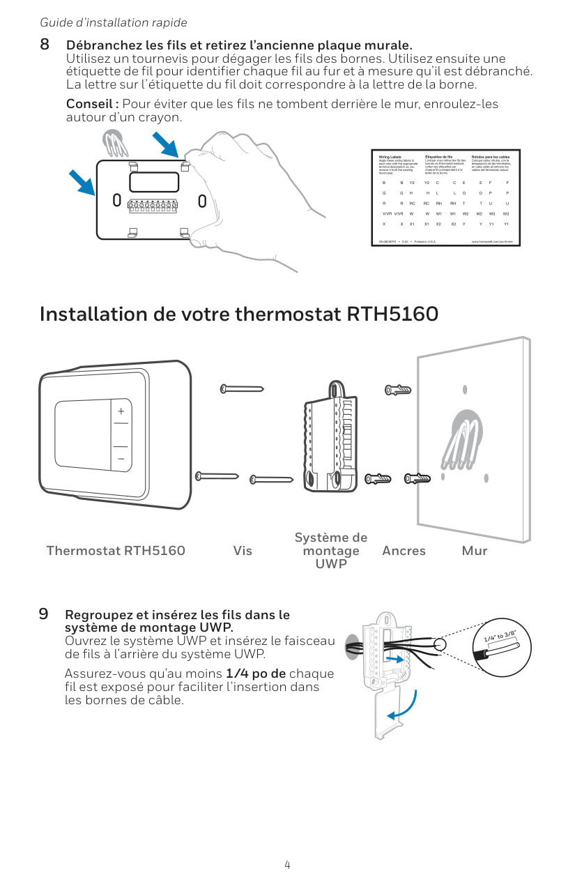
4 Guide d’installation rapide 8 Débranchez les fils et retirez l’ancienne plaque murale. Utilisez un tournevis pour dégager les fils des bornes. Utilisez ensuite une étiquette de fil pour identifier chaque fil au fur et à mesure qu’il est débranché. La lettre sur l’étiquette du fil doit correspondre à la lettre de la borne. Conseil : Pour éviter que les fils ne tombent derrière le mur, enroulez-les autour d’un crayon. Installation de votre thermostat RTH5160 9 Regroupez et insérez les fils dans le système de montage UWP. Ouvrez le système UWP et insérez le faisceau de fils à l’arrière du système UWP. Assurez-vous qu’au moins 1/4 po de chaque fil est exposé pour faciliter l’insertion dans les bornes de câble. Thermostat RTH5160 Vis Système de montage
Uwp
Ancres Mur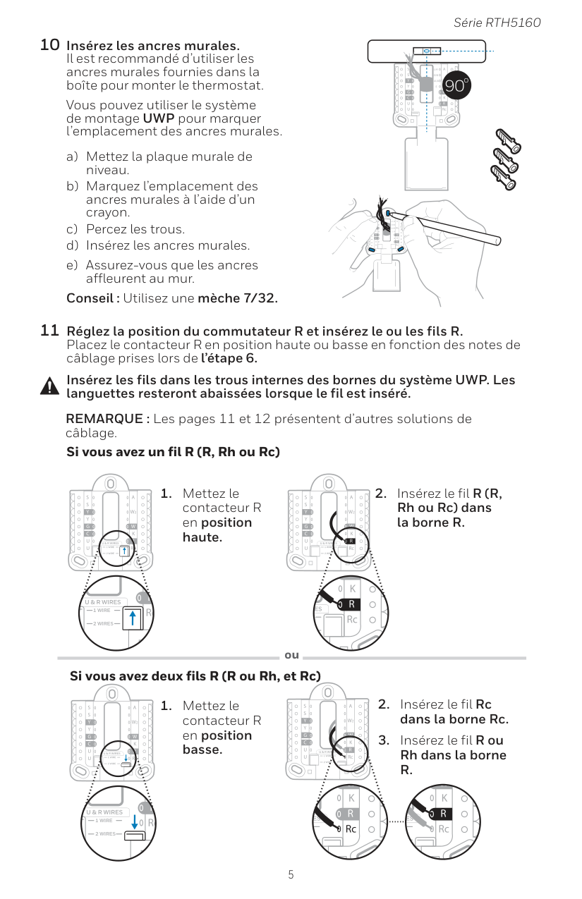
5 Série RTH5160 10 Insérez les ancres murales. Il est recommandé d’utiliser les ancres murales fournies dans la boîte pour monter le thermostat. Vous pouvez utiliser le système de montage UWP pour marquer l’emplacement des ancres murales. a) Mettez la plaque murale de niveau. b) Marquez l’emplacement des ancres murales à l’aide d’un crayon. c) Percez les trous. d) Insérez les ancres murales. e) Assurez-vous que les ancres affleurent au mur. Conseil : Utilisez une mèche 7/32. Insérez les fils dans les trous internes des bornes du système UWP. Les languettes resteront abaissées lorsque le fil est inséré. Si vous avez un fil R (R, Rh ou Rc) Si vous avez deux fils R (R ou Rh, et Rc) ou
R.
11 Réglez la position du commutateur R et insérez le ou les fils R. Placez le contacteur R en position haute ou basse en fonction des notes de câblage prises lors de l’étape 6. REMARQUE : Les pages 11 et 12 présentent d’autres solutions de câblage.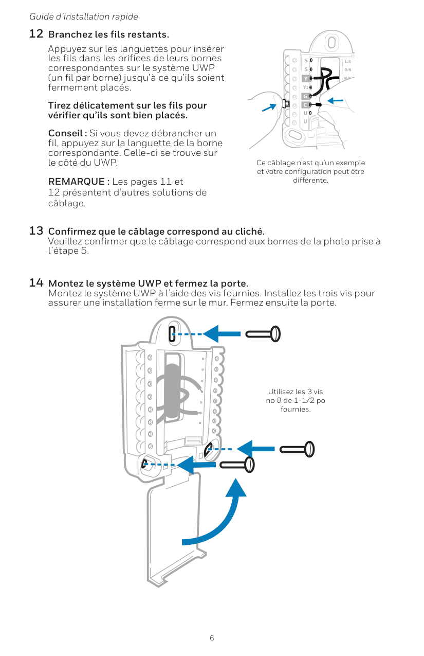
6 Guide d’installation rapide 13 Confirmez que le câblage correspond au cliché. Veuillez confirmer que le câblage correspond aux bornes de la photo prise à l’étape 5. 14 Montez le système UWP et fermez la porte. Montez le système UWP à l’aide des vis fournies. Installez les trois vis pour assurer une installation ferme sur le mur. Fermez ensuite la porte. Utilisez les 3 vis no 8 de 1-1/2 po fournies. 12 Branchez les fils restants. Appuyez sur les languettes pour insérer les fils dans les orifices de leurs bornes correspondantes sur le système UWP (un fil par borne) jusqu’à ce qu’ils soient fermement placés. Tirez délicatement sur les fils pour vérifier qu’ils sont bien placés. Conseil : Si vous devez débrancher un fil, appuyez sur la languette de la borne correspondante. Celle-ci se trouve sur le côté du UWP. REMARQUE : Les pages 11 et 12 présentent d’autres solutions de câblage. Ce câblage n’est qu’un exemple et votre configuration peut être différente.
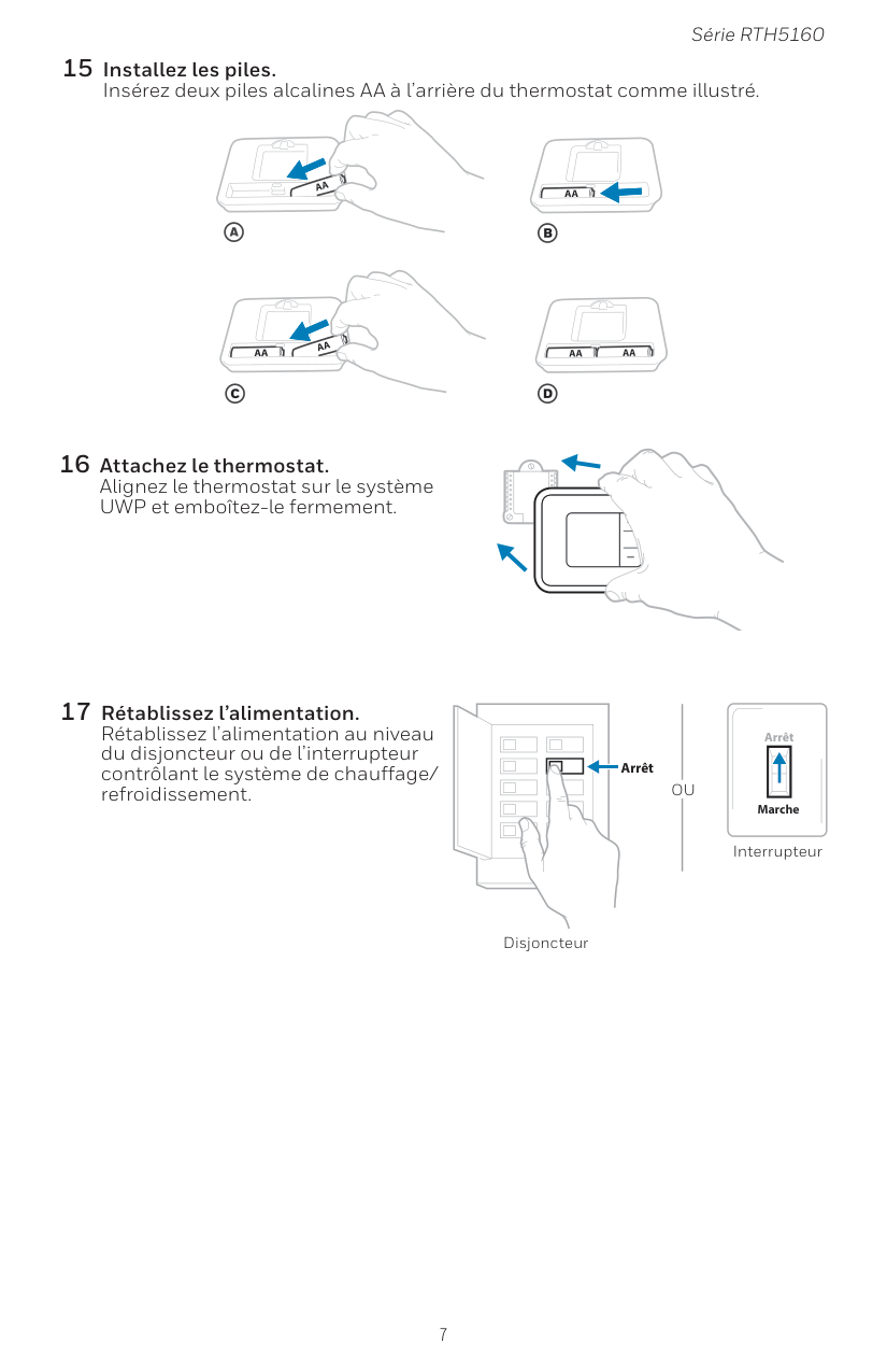
7 Série RTH5160 15 Installez les piles. Insérez deux piles alcalines AA à l’arrière du thermostat comme illustré. 16 Attachez le thermostat. Alignez le thermostat sur le système UWP et emboîtez-le fermement. 17 Rétablissez l’alimentation. Rétablissez l’alimentation au niveau du disjoncteur ou de l’interrupteur contrôlant le système de chauffage/ refroidissement. Arrêt Marche Arrêt Interrupteur Disjoncteur
Ou
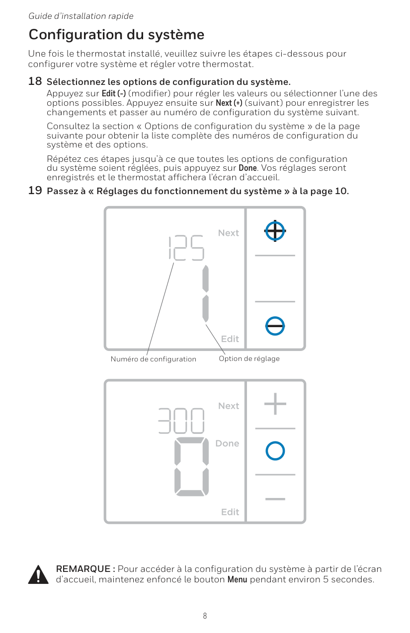
8 Guide d’installation rapide Une fois le thermostat installé, veuillez suivre les étapes ci-dessous pour configurer votre système et régler votre thermostat. 18 Sélectionnez les options de configuration du système. Appuyez sur Edit (-) (modifier) pour régler les valeurs ou sélectionner l’une des options possibles. Appuyez ensuite sur Next (+) (suivant) pour enregistrer les changements et passer au numéro de configuration du système suivant. Consultez la section « Options de configuration du système » de la page suivante pour obtenir la liste complète des numéros de configuration du système et des options. Répétez ces étapes jusqu’à ce que toutes les options de configuration du système soient réglées, puis appuyez sur Done. Vos réglages seront enregistrés et le thermostat affichera l’écran d’accueil. 19 Passez à « Réglages du fonctionnement du système » à la page 10. Configuration du système Numéro de configuration Option de réglage REMARQUE : Pour accéder à la configuration du système à partir de l’écran d’accueil, maintenez enfoncé le bouton Menu pendant environ 5 secondes.
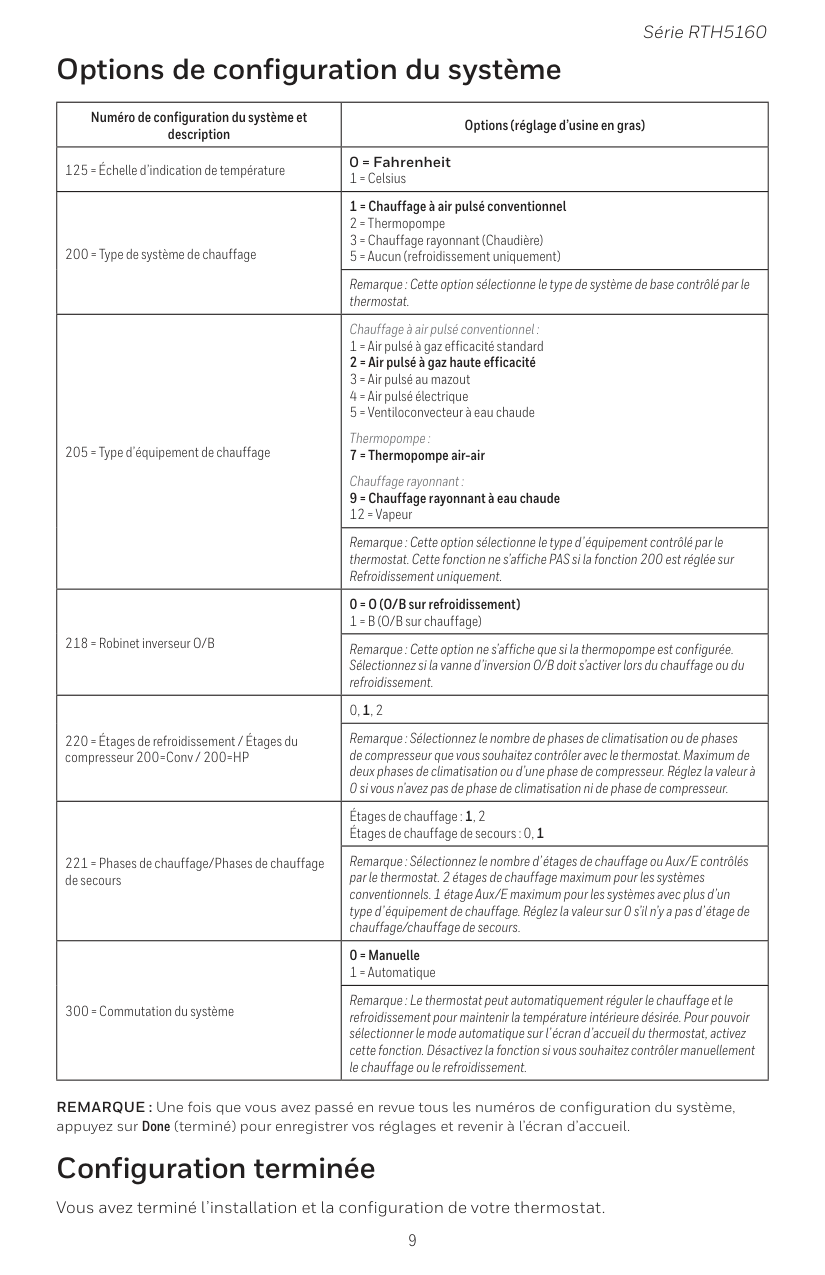
9 Série RTH5160 Numéro de configuration du système et description Options (réglage d’usine en gras) 125 = Échelle d’indication de température 0 = Fahrenheit 1 = Celsius 200 = Type de système de chauffage 1 = Chauffage à air pulsé conventionnel 2 = Thermopompe 3 = Chauffage rayonnant (Chaudière) 5 = Aucun (refroidissement uniquement) Remarque : Cette option sélectionne le type de système de base contrôlé par le thermostat. 205 = Type d’équipement de chauffage Chauffage à air pulsé conventionnel : 1 = Air pulsé à gaz efficacité standard 2 = Air pulsé à gaz haute efficacité 3 = Air pulsé au mazout 4 = Air pulsé électrique 5 = Ventiloconvecteur à eau chaude Thermopompe : 7 = Thermopompe air-air Chauffage rayonnant : 9 = Chauffage rayonnant à eau chaude 12 = Vapeur Remarque : Cette option sélectionne le type d’équipement contrôlé par le thermostat. Cette fonction ne s’affiche PAS si la fonction 200 est réglée sur Refroidissement uniquement. 218 = Robinet inverseur O/B 0 = O (O/B sur refroidissement) 1 = B (O/B sur chauffage) Remarque : Cette option ne s’affiche que si la thermopompe est configurée. Sélectionnez si la vanne d’inversion O/B doit s’activer lors du chauffage ou du refroidissement. 220 = Étages de refroidissement / Étages du compresseur 200=Conv / 200=HP 0, 1, 2 Remarque : Sélectionnez le nombre de phases de climatisation ou de phases de compresseur que vous souhaitez contrôler avec le thermostat. Maximum de deux phases de climatisation ou d’une phase de compresseur. Réglez la valeur à 0 si vous n’avez pas de phase de climatisation ni de phase de compresseur. 221 = Phases de chauffage/Phases de chauffage de secours Étages de chauffage : 1, 2 Étages de chauffage de secours : 0, 1 Remarque : Sélectionnez le nombre d’étages de chauffage ou Aux/E contrôlés par le thermostat. 2 étages de chauffage maximum pour les systèmes conventionnels. 1 étage Aux/E maximum pour les systèmes avec plus d’un type d’équipement de chauffage. Réglez la valeur sur 0 s’il n’y a pas d’étage de chauffage/chauffage de secours. 300 = Commutation du système 0 = Manuelle 1 = Automatique Remarque : Le thermostat peut automatiquement réguler le chauffage et le refroidissement pour maintenir la température intérieure désirée. Pour pouvoir sélectionner le mode automatique sur l’écran d’accueil du thermostat, activez cette fonction. Désactivez la fonction si vous souhaitez contrôler manuellement le chauffage ou le refroidissement. REMARQUE : Une fois que vous avez passé en revue tous les numéros de configuration du système, appuyez sur Done (terminé) pour enregistrer vos réglages et revenir à l’écran d’accueil. Options de configuration du système Configuration terminée Vous avez terminé l’installation et la configuration de votre thermostat.
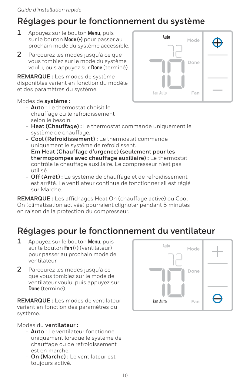
10 Guide d’installation rapide Réglages pour le fonctionnement du ventilateur 1 Appuyez sur le bouton Menu, puis sur le bouton Fan (+) (ventilateur) pour passer au prochain mode de ventilateur. 2 Parcourez les modes jusqu’à ce que vous tombiez sur le mode de ventilateur voulu, puis appuyez sur Done (terminé). REMARQUE : Les modes de ventilateur varient en fonction des paramètres du système. Modes du ventilateur : ‒‒ Auto : Le ventilateur fonctionne uniquement lorsque le système de chauffage ou de refroidissement est en marche. ‒‒ On (Marche) : Le ventilateur est toujours activé. Réglages pour le fonctionnement du système 1 Appuyez sur le bouton Menu, puis sur le bouton Mode (+) pour passer au prochain mode du système accessible. 2 Parcourez les modes jusqu’à ce que vous tombiez sur le mode du système voulu, puis appuyez sur Done (terminé). REMARQUE : Les modes de système disponibles varient en fonction du modèle et des paramètres du système. Modes de système : ‒‒ Auto : Le thermostat choisit le chauffage ou le refroidissement selon le besoin. ‒‒ Heat (Chauffage) : Le thermostat commande uniquement le système de chauffage. ‒‒ Cool (Refroidissement) : Le thermostat commande uniquement le système de refroidissent. ‒‒ Em Heat (Chauffage d’urgence) (seulement pour les thermopompes avec chauffage auxiliaire) : Le thermostat contrôle le chauffage auxiliaire. Le compresseur n’est pas utilisé. ‒‒ Off (Arrêt) : Le système de chauffage et de refroidissement est arrêté. Le ventilateur continue de fonctionner sil est réglé sur Marche. REMARQUE : Les affichages Heat On (chauffage activé) ou Cool On (climatisation activée) pourraient clignoter pendant 5 minutes en raison de la protection du compresseur.
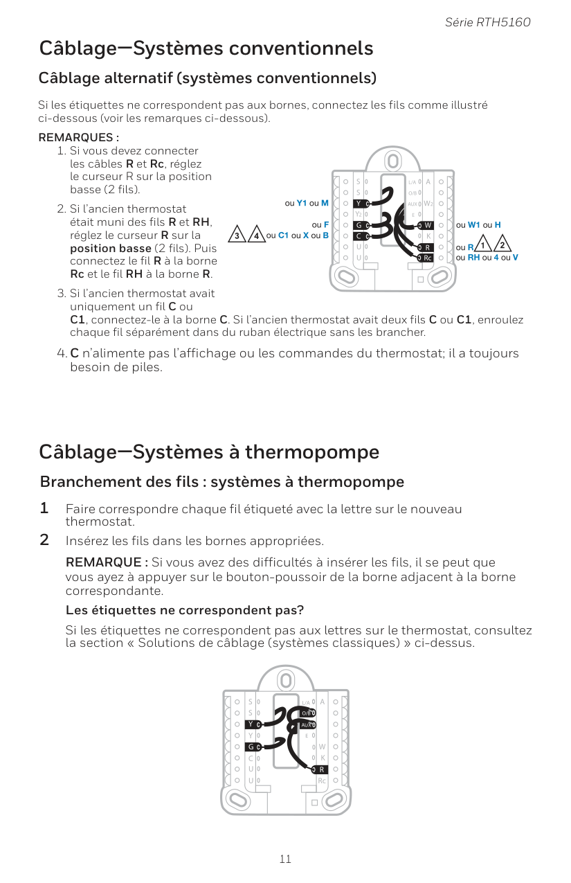
11 Série RTH5160 Câblage—Systèmes conventionnels Câblage alternatif (systèmes conventionnels) Si les étiquettes ne correspondent pas aux bornes, connectez les fils comme illustré ci-dessous (voir les remarques ci-dessous).
Remarques :
Aux
S
S
Y
U
U
G
C
Y
A
RcW
K
W2
R
L/A
O/B
E
Aux
S
S
U
U
G
C
Y
A
RcW
K
W2
R
L/A
O/B
E
Y
4 2 2 3 ou Y1 ou M ou F ou C1 ou X ou B ou W1 ou H ou R ou RH ou 4 ou V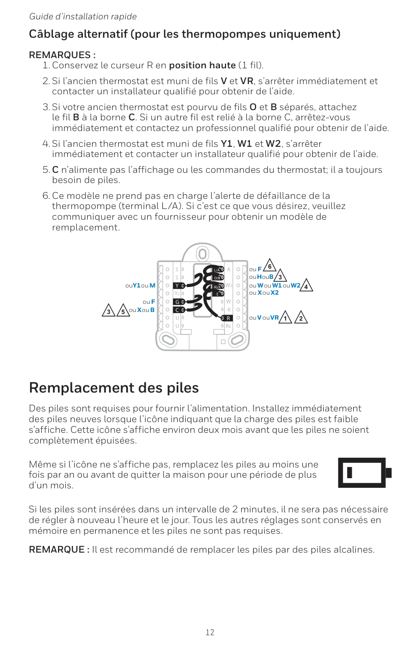
12 Guide d’installation rapide Câblage alternatif (pour les thermopompes uniquement)
Remarques :
Aux
S
S
Y
U
U
G
C
Y
A
RcW
K
W2
R
L/A
O/B
E
3 5 3 4 ou X ou B ou F ou Y1 ou M 2 ou H ou B ou V ou VR ou W ou W1 ou W2 ou X ou X2 ou F 2 1 6
13 Série RTH5160 Écran d’alerte Numéro Alerte/Rappel Définition 170 Erreur de mémoire interne La thermopompe nécessite un entretien. Veuillez remplacer le thermostat. 173 Erreur de capteur de température du thermostat) Le capteur du thermostat a rencontré une erreur. Veuillez remplacer le thermostat. 405 Alerte piles presque déchargées Les piles commencent à se décharger. Remplacez- les dans un délai de deux mois. 407 Piles déchargées (seuil critique) Les piles sont presque épuisées et doivent être remplacées dès que possible. Codes d’alerte 1 Vous verrez l’icône et le numéro d’alerte à l’écran. 2 Appuyez sur Next (+) (suivant) pour voir d’autres alertes, s’il y a lieu. Puis, appuyez sur Done (terminé) pour revenir à l’écran d’accueil. REMARQUE : Si l’alerte est critique, il est possible que vous ne puissiez pas accéder à l’écran d’accueil. Vous devrez alors communiquer avec un professionnel en CVCA.
14 Guide d’installation rapide En cas de difficultés avec le thermostat, essayer les suggestions suivantes. La plupart des problèmes peuvent être réglés rapidement et facilement. Rien n’apparaît à l’écran Assurez-vous que des piles alcalines AA bien chargées sont cor rectement installées (consultez la page 7. Impossible de changer le réglage du système à Refroidissement Consultez l’option de configuration du système 220 pour vous assurer que les options sont définies sur 1 ou 2 (consultez la page 9). Le ventilateur ne se met pas en marche pas lorsque de la chaleur est requise Consultez l’option de configuration du système 205 pour véri fier qu’elle est réglée en fonction de l’équipement de chauffage (consultez la page 9). Le système de chauffage fonctionne en mode re froidissement Consultez l’option de configuration du système 200 ou 218 pour vérifier qu’elle est réglée en fonction de l’équipement de chauffage et de refroidissement (consultez la page 9). Le système de chauffage ou de refroidissement ne répond pas Appuyez sur Menu, puis sur Mode pour régler le système à Heat (chauffage). Assurez-vous que la température réglée est supéri eure à la température intérieure. Appuyez sur Menu, puis sur Mode pour régler le système à Cool (climatisation). Assurez-vous que la température réglée est inférieure à la température intérieure. Vérifiez le disjoncteur et réinitialisez-le si nécessaire. Assurez-vous que l’interrupteur de marche-arrêt du système de chauffage et de refroidissement est sur marche. Assurez-vous que la porte de l’appareil de chauffage est bien fermée. Attendez 5 minutes que le système réponde. Chauffage en marche/ Refroidissement en marche clignote à l’écran La fonction de protection du compresseur est activée. Attendez 5 minutes que le système se remette en marche en toute sécu rité sans endommager le compresseur. La thermopompe émet de l’air frais en mode chauffage, ou de l’air chaud en mode re- froidissement Consultez l’option de configuration du système 200 ou 218 pour vérifier qu’elle est réglée en fonction de l’équipement de chauffage et de refroidissement (consultez la page 9). Dépannage
15 Série RTH5160 Honeywell garantit ce produit, à l’exception des piles, contre tout défaut de pièce ou de main-d’œuvre, durant une période d’un (1) an à partir de la date d’achat par le consommateur si le produit est utilisé et entretenu convenablement. En cas de défectuosité ou de mauvais fonctionnement pendant la période de garantie, Honeywell remplacera ou réparera le produit, à sa discrétion. Si le produit est défectueux, (i) renvoyez-le avec la facture ou une autre preuve d’achat date au lieu d’achat; ou (ii) appelez le service à la clientèle de Honeywell en composant le 1-800-468-
En Aucun Cas Responsable Des Pertes Ou Dommages, Y Compris
Les Dommages Indirects Ou Accessoires Découlant Directement
Ou Indirectement D’Une Violation Quelconque D’Une Garantie,
Expresse Ou Tacite, Applicable Au Présent Produit, Ou Toute Autre
DÉFECTUOSITÉ DU PRÉSENT PRODUIT. Certains États ne permettent pas l’exclusion ou la limitation des dommages indirects ou consécutifs, de sorte que cette limitation peut ne pas s’appliquer à vous.Cette Garantie Est La Seule Garantie Expresse Faite Par Honeywell
Pour Ce Produit. La Durée De Toute Garantie Implicite, Incluant Les
Garanties De Qualité Marchande Ou D’Adaptation À Une Utilisation
Particulière, Est Limitée Par Les Présentes À La Période D’Une
Année De La Présente Garantie.
Certaines provinces ne permettent pas de limiter la durée des garanties tacites et, par conséquent, la présente limitation peut ne pas s’appliquer. La présente garantie donne au consommateur des droits spécifiques et certains autres droits qui peuvent varier d’une province à l’autre. Pour toute question concernant cette garantie, veuillez écrire au service des Relations avec la clientèle de Honeywell à l’adresse suivante : Customer Relations, 1985 Douglas Dr, Golden Valley, MN 55422, ou veuillez appeler le 1-800-468-1502. Au Canada, veuillez vous adresser à Retail Products, Honeywell Limited/Honeywell Limitée, 35 Dynamic Drive, Toronto, Ontario M1V4Z9. Garantie limitée de 1 an